JP2019528957A - Negative pressure wound treatment apparatus and method with integrated electronics - Google Patents
Negative pressure wound treatment apparatus and method with integrated electronics Download PDFInfo
- Publication number
- JP2019528957A JP2019528957A JP2019516606A JP2019516606A JP2019528957A JP 2019528957 A JP2019528957 A JP 2019528957A JP 2019516606 A JP2019516606 A JP 2019516606A JP 2019516606 A JP2019516606 A JP 2019516606A JP 2019528957 A JP2019528957 A JP 2019528957A
- Authority
- JP
- Japan
- Prior art keywords
- wound
- area
- layer
- wound dressing
- negative pressure
- Prior art date
- Legal status (The legal status is an assumption and is not a legal conclusion. Google has not performed a legal analysis and makes no representation as to the accuracy of the status listed.)
- Pending
Links
- 206010052428 Wound Diseases 0.000 title abstract description 302
- 208000027418 Wounds and injury Diseases 0.000 title abstract description 301
- 238000000034 method Methods 0.000 title abstract description 29
- 239000002250 absorbent Substances 0.000 claims abstract description 130
- 230000002745 absorbent Effects 0.000 claims abstract description 130
- 125000006850 spacer group Chemical group 0.000 claims abstract description 98
- 239000000463 material Substances 0.000 claims description 101
- 239000012530 fluid Substances 0.000 claims description 58
- 230000007246 mechanism Effects 0.000 claims description 53
- 238000007373 indentation Methods 0.000 claims description 22
- 239000011248 coating agent Substances 0.000 claims description 20
- 238000000576 coating method Methods 0.000 claims description 20
- 230000002209 hydrophobic effect Effects 0.000 claims description 19
- 238000004891 communication Methods 0.000 claims description 16
- 239000012528 membrane Substances 0.000 claims description 12
- 230000000845 anti-microbial effect Effects 0.000 claims description 11
- 239000004599 antimicrobial Substances 0.000 claims description 11
- 239000010410 layer Substances 0.000 description 297
- 238000010521 absorption reaction Methods 0.000 description 25
- 238000009581 negative-pressure wound therapy Methods 0.000 description 9
- 230000008569 process Effects 0.000 description 9
- 210000001519 tissue Anatomy 0.000 description 9
- 239000006096 absorbing agent Substances 0.000 description 7
- 230000000873 masking effect Effects 0.000 description 7
- 210000000416 exudates and transudate Anatomy 0.000 description 6
- 238000002560 therapeutic procedure Methods 0.000 description 6
- 238000005538 encapsulation Methods 0.000 description 4
- 239000006260 foam Substances 0.000 description 4
- 239000004642 Polyimide Substances 0.000 description 3
- 230000009931 harmful effect Effects 0.000 description 3
- 230000003287 optical effect Effects 0.000 description 3
- 229920001721 polyimide Polymers 0.000 description 3
- 239000011253 protective coating Substances 0.000 description 3
- 230000002829 reductive effect Effects 0.000 description 3
- 241001272720 Medialuna californiensis Species 0.000 description 2
- 238000009825 accumulation Methods 0.000 description 2
- 230000008901 benefit Effects 0.000 description 2
- 230000005540 biological transmission Effects 0.000 description 2
- 230000001684 chronic effect Effects 0.000 description 2
- 230000023753 dehiscence Effects 0.000 description 2
- 238000009826 distribution Methods 0.000 description 2
- 238000010292 electrical insulation Methods 0.000 description 2
- 230000035876 healing Effects 0.000 description 2
- 208000014674 injury Diseases 0.000 description 2
- 230000001788 irregular Effects 0.000 description 2
- 239000007788 liquid Substances 0.000 description 2
- 238000005192 partition Methods 0.000 description 2
- 238000000926 separation method Methods 0.000 description 2
- 229910000679 solder Inorganic materials 0.000 description 2
- 239000012780 transparent material Substances 0.000 description 2
- 230000008733 trauma Effects 0.000 description 2
- 208000019901 Anxiety disease Diseases 0.000 description 1
- 241000894006 Bacteria Species 0.000 description 1
- 208000034656 Contusions Diseases 0.000 description 1
- 102000004127 Cytokines Human genes 0.000 description 1
- 108090000695 Cytokines Proteins 0.000 description 1
- 206010056340 Diabetic ulcer Diseases 0.000 description 1
- 206010063560 Excessive granulation tissue Diseases 0.000 description 1
- 208000035874 Excoriation Diseases 0.000 description 1
- 208000034693 Laceration Diseases 0.000 description 1
- 206010030113 Oedema Diseases 0.000 description 1
- 229920005830 Polyurethane Foam Polymers 0.000 description 1
- 208000004210 Pressure Ulcer Diseases 0.000 description 1
- 206010048625 Skin maceration Diseases 0.000 description 1
- 239000004830 Super Glue Substances 0.000 description 1
- 208000002847 Surgical Wound Diseases 0.000 description 1
- 206010044546 Traumatic ulcer Diseases 0.000 description 1
- 208000025865 Ulcer Diseases 0.000 description 1
- 230000003187 abdominal effect Effects 0.000 description 1
- 238000005299 abrasion Methods 0.000 description 1
- 230000001154 acute effect Effects 0.000 description 1
- 230000036506 anxiety Effects 0.000 description 1
- 230000001580 bacterial effect Effects 0.000 description 1
- 230000004888 barrier function Effects 0.000 description 1
- 239000011324 bead Substances 0.000 description 1
- 230000009286 beneficial effect Effects 0.000 description 1
- 230000015572 biosynthetic process Effects 0.000 description 1
- 230000017531 blood circulation Effects 0.000 description 1
- 230000008859 change Effects 0.000 description 1
- 238000004140 cleaning Methods 0.000 description 1
- 230000000295 complement effect Effects 0.000 description 1
- 230000009519 contusion Effects 0.000 description 1
- 230000007547 defect Effects 0.000 description 1
- 230000000994 depressogenic effect Effects 0.000 description 1
- 230000000694 effects Effects 0.000 description 1
- 238000005516 engineering process Methods 0.000 description 1
- FGBJXOREULPLGL-UHFFFAOYSA-N ethyl cyanoacrylate Chemical compound CCOC(=O)C(=C)C#N FGBJXOREULPLGL-UHFFFAOYSA-N 0.000 description 1
- 239000000835 fiber Substances 0.000 description 1
- 239000008187 granular material Substances 0.000 description 1
- 210000001126 granulation tissue Anatomy 0.000 description 1
- 208000015181 infectious disease Diseases 0.000 description 1
- 230000004054 inflammatory process Effects 0.000 description 1
- 239000011810 insulating material Substances 0.000 description 1
- 230000000670 limiting effect Effects 0.000 description 1
- 238000004519 manufacturing process Methods 0.000 description 1
- 230000004048 modification Effects 0.000 description 1
- 238000012986 modification Methods 0.000 description 1
- 239000004033 plastic Substances 0.000 description 1
- 229920003023 plastic Polymers 0.000 description 1
- 239000004814 polyurethane Substances 0.000 description 1
- 239000011527 polyurethane coating Substances 0.000 description 1
- 239000011496 polyurethane foam Substances 0.000 description 1
- 238000011176 pooling Methods 0.000 description 1
- 230000001737 promoting effect Effects 0.000 description 1
- 230000000717 retained effect Effects 0.000 description 1
- 239000000565 sealant Substances 0.000 description 1
- 238000007789 sealing Methods 0.000 description 1
- 229910052710 silicon Inorganic materials 0.000 description 1
- 239000010703 silicon Substances 0.000 description 1
- 239000004447 silicone coating Substances 0.000 description 1
- 239000002356 single layer Substances 0.000 description 1
- 238000001356 surgical procedure Methods 0.000 description 1
- 230000001225 therapeutic effect Effects 0.000 description 1
- 238000003856 thermoforming Methods 0.000 description 1
- 230000009772 tissue formation Effects 0.000 description 1
- 230000000699 topical effect Effects 0.000 description 1
- 230000000472 traumatic effect Effects 0.000 description 1
- 231100000397 ulcer Toxicity 0.000 description 1
- 238000007666 vacuum forming Methods 0.000 description 1
- 230000035899 viability Effects 0.000 description 1
- XLYOFNOQVPJJNP-UHFFFAOYSA-N water Substances O XLYOFNOQVPJJNP-UHFFFAOYSA-N 0.000 description 1
- 230000010388 wound contraction Effects 0.000 description 1
- 230000029663 wound healing Effects 0.000 description 1
Images


Classifications
-
- A—HUMAN NECESSITIES
- A61—MEDICAL OR VETERINARY SCIENCE; HYGIENE
- A61M—DEVICES FOR INTRODUCING MEDIA INTO, OR ONTO, THE BODY; DEVICES FOR TRANSDUCING BODY MEDIA OR FOR TAKING MEDIA FROM THE BODY; DEVICES FOR PRODUCING OR ENDING SLEEP OR STUPOR
- A61M1/00—Suction or pumping devices for medical purposes; Devices for carrying-off, for treatment of, or for carrying-over, body-liquids; Drainage systems
- A61M1/90—Negative pressure wound therapy devices, i.e. devices for applying suction to a wound to promote healing, e.g. including a vacuum dressing
- A61M1/96—Suction control thereof
- A61M1/962—Suction control thereof having pumping means on the suction site, e.g. miniature pump on dressing or dressing capable of exerting suction
-
- A—HUMAN NECESSITIES
- A61—MEDICAL OR VETERINARY SCIENCE; HYGIENE
- A61F—FILTERS IMPLANTABLE INTO BLOOD VESSELS; PROSTHESES; DEVICES PROVIDING PATENCY TO, OR PREVENTING COLLAPSING OF, TUBULAR STRUCTURES OF THE BODY, e.g. STENTS; ORTHOPAEDIC, NURSING OR CONTRACEPTIVE DEVICES; FOMENTATION; TREATMENT OR PROTECTION OF EYES OR EARS; BANDAGES, DRESSINGS OR ABSORBENT PADS; FIRST-AID KITS
- A61F13/00—Bandages or dressings; Absorbent pads
- A61F13/05—Bandages or dressings; Absorbent pads specially adapted for use with sub-pressure or over-pressure therapy, wound drainage or wound irrigation, e.g. for use with negative-pressure wound therapy [NPWT]
-
- A—HUMAN NECESSITIES
- A61—MEDICAL OR VETERINARY SCIENCE; HYGIENE
- A61M—DEVICES FOR INTRODUCING MEDIA INTO, OR ONTO, THE BODY; DEVICES FOR TRANSDUCING BODY MEDIA OR FOR TAKING MEDIA FROM THE BODY; DEVICES FOR PRODUCING OR ENDING SLEEP OR STUPOR
- A61M1/00—Suction or pumping devices for medical purposes; Devices for carrying-off, for treatment of, or for carrying-over, body-liquids; Drainage systems
- A61M1/90—Negative pressure wound therapy devices, i.e. devices for applying suction to a wound to promote healing, e.g. including a vacuum dressing
- A61M1/96—Suction control thereof
- A61M1/964—Suction control thereof having venting means on or near the dressing
-
- A—HUMAN NECESSITIES
- A61—MEDICAL OR VETERINARY SCIENCE; HYGIENE
- A61F—FILTERS IMPLANTABLE INTO BLOOD VESSELS; PROSTHESES; DEVICES PROVIDING PATENCY TO, OR PREVENTING COLLAPSING OF, TUBULAR STRUCTURES OF THE BODY, e.g. STENTS; ORTHOPAEDIC, NURSING OR CONTRACEPTIVE DEVICES; FOMENTATION; TREATMENT OR PROTECTION OF EYES OR EARS; BANDAGES, DRESSINGS OR ABSORBENT PADS; FIRST-AID KITS
- A61F13/00—Bandages or dressings; Absorbent pads
- A61F13/15—Absorbent pads, e.g. sanitary towels, swabs or tampons for external or internal application to the body; Supporting or fastening means therefor; Tampon applicators
- A61F13/84—Accessories, not otherwise provided for, for absorbent pads
- A61F2013/8476—Accessories, not otherwise provided for, for absorbent pads with various devices or method
- A61F2013/8479—Accessories, not otherwise provided for, for absorbent pads with various devices or method including electric or magnetic devices
- A61F2013/8482—Accessories, not otherwise provided for, for absorbent pads with various devices or method including electric or magnetic devices including numeric control, e.g. using computer
-
- A—HUMAN NECESSITIES
- A61—MEDICAL OR VETERINARY SCIENCE; HYGIENE
- A61F—FILTERS IMPLANTABLE INTO BLOOD VESSELS; PROSTHESES; DEVICES PROVIDING PATENCY TO, OR PREVENTING COLLAPSING OF, TUBULAR STRUCTURES OF THE BODY, e.g. STENTS; ORTHOPAEDIC, NURSING OR CONTRACEPTIVE DEVICES; FOMENTATION; TREATMENT OR PROTECTION OF EYES OR EARS; BANDAGES, DRESSINGS OR ABSORBENT PADS; FIRST-AID KITS
- A61F13/00—Bandages or dressings; Absorbent pads
- A61F13/15—Absorbent pads, e.g. sanitary towels, swabs or tampons for external or internal application to the body; Supporting or fastening means therefor; Tampon applicators
- A61F13/84—Accessories, not otherwise provided for, for absorbent pads
- A61F2013/8494—Accessories, not otherwise provided for, for absorbent pads including pumping devices
-
- A—HUMAN NECESSITIES
- A61—MEDICAL OR VETERINARY SCIENCE; HYGIENE
- A61M—DEVICES FOR INTRODUCING MEDIA INTO, OR ONTO, THE BODY; DEVICES FOR TRANSDUCING BODY MEDIA OR FOR TAKING MEDIA FROM THE BODY; DEVICES FOR PRODUCING OR ENDING SLEEP OR STUPOR
- A61M1/00—Suction or pumping devices for medical purposes; Devices for carrying-off, for treatment of, or for carrying-over, body-liquids; Drainage systems
- A61M1/71—Suction drainage systems
- A61M1/78—Means for preventing overflow or contamination of the pumping systems
- A61M1/784—Means for preventing overflow or contamination of the pumping systems by filtering, sterilising or disinfecting the exhaust air, e.g. swellable filter valves
-
- A—HUMAN NECESSITIES
- A61—MEDICAL OR VETERINARY SCIENCE; HYGIENE
- A61M—DEVICES FOR INTRODUCING MEDIA INTO, OR ONTO, THE BODY; DEVICES FOR TRANSDUCING BODY MEDIA OR FOR TAKING MEDIA FROM THE BODY; DEVICES FOR PRODUCING OR ENDING SLEEP OR STUPOR
- A61M2205/00—General characteristics of the apparatus
- A61M2205/50—General characteristics of the apparatus with microprocessors or computers
-
- A—HUMAN NECESSITIES
- A61—MEDICAL OR VETERINARY SCIENCE; HYGIENE
- A61M—DEVICES FOR INTRODUCING MEDIA INTO, OR ONTO, THE BODY; DEVICES FOR TRANSDUCING BODY MEDIA OR FOR TAKING MEDIA FROM THE BODY; DEVICES FOR PRODUCING OR ENDING SLEEP OR STUPOR
- A61M2205/00—General characteristics of the apparatus
- A61M2205/58—Means for facilitating use, e.g. by people with impaired vision
- A61M2205/583—Means for facilitating use, e.g. by people with impaired vision by visual feedback
-
- A—HUMAN NECESSITIES
- A61—MEDICAL OR VETERINARY SCIENCE; HYGIENE
- A61M—DEVICES FOR INTRODUCING MEDIA INTO, OR ONTO, THE BODY; DEVICES FOR TRANSDUCING BODY MEDIA OR FOR TAKING MEDIA FROM THE BODY; DEVICES FOR PRODUCING OR ENDING SLEEP OR STUPOR
- A61M2205/00—General characteristics of the apparatus
- A61M2205/58—Means for facilitating use, e.g. by people with impaired vision
- A61M2205/587—Lighting arrangements
-
- A—HUMAN NECESSITIES
- A61—MEDICAL OR VETERINARY SCIENCE; HYGIENE
- A61M—DEVICES FOR INTRODUCING MEDIA INTO, OR ONTO, THE BODY; DEVICES FOR TRANSDUCING BODY MEDIA OR FOR TAKING MEDIA FROM THE BODY; DEVICES FOR PRODUCING OR ENDING SLEEP OR STUPOR
- A61M2205/00—General characteristics of the apparatus
- A61M2205/75—General characteristics of the apparatus with filters
- A61M2205/7518—General characteristics of the apparatus with filters bacterial
Landscapes
- Health & Medical Sciences (AREA)
- Heart & Thoracic Surgery (AREA)
- General Health & Medical Sciences (AREA)
- Engineering & Computer Science (AREA)
- Biomedical Technology (AREA)
- Life Sciences & Earth Sciences (AREA)
- Animal Behavior & Ethology (AREA)
- Vascular Medicine (AREA)
- Public Health (AREA)
- Veterinary Medicine (AREA)
- Anesthesiology (AREA)
- Hematology (AREA)
- Media Introduction/Drainage Providing Device (AREA)
- External Artificial Organs (AREA)
Abstract
開示された実施形態は、創傷治療の装置及び方法に関する。一部の実施形態では、創傷被覆材装置は、創傷接触層、創傷接触層上の第一エリアと第二エリア、および創傷接触層と、第一エリアと、第二エリアとを覆うように構成されるカバー層を備え得る。第一エリアは、スペーサ層およびスペーサ層上の吸収層を含み得る。第二エリアは、陰圧源および/または電子構成要素を含む電子カセットまたはクレードルを含み得る。【選択図】図1AThe disclosed embodiments relate to an apparatus and method for wound treatment. In some embodiments, the wound dressing device is configured to cover the wound contact layer, the first and second areas on the wound contact layer, and the wound contact layer, the first area, and the second area. A cover layer may be provided. The first area can include a spacer layer and an absorbent layer on the spacer layer. The second area may include an electronic cassette or cradle that includes a negative pressure source and / or electronic components. [Selection] Figure 1A
Description
関連出願の相互参照
本出願は、2016年9月30日出願の米国仮特許出願第62/402,146号、2016年9月30日出願の米国仮特許出願第62/402,298号、2016年9月30日出願の米国仮特許出願第62/402,382号に対する優先権を主張する。これらの出願はそれらの全体が参照により本明細書に組み込まれ、本開示の一部分をなす。
CROSS REFERENCE TO RELATED APPLICATIONS This application is based on US Provisional Patent Application No. 62 / 402,146, filed September 30, 2016, and US Provisional Patent Application No. 62 / 402,298, filed September 30, 2016. Claims priority to US Provisional Patent Application No. 62 / 402,382, filed Sep. 30, These applications are hereby incorporated by reference in their entirety and form part of the present disclosure.
本明細書に記載の実施形態は、例えば、陰圧創傷療法と組み合わせて被覆材を使用する、創傷を治療する装置、システム、及び方法に関する。
関連技術の説明
Embodiments described herein relate to devices, systems, and methods for treating wounds, for example, using dressings in combination with negative pressure wound therapy.
Explanation of related technology
大きすぎて自然には閉じられない、もしくはそうでなければ、創傷の部位への陰圧の適用では治癒しない、開放創または慢性創傷の治療は、当該技術分野ではよく知られている。現在当該技術分野で知られている陰圧創傷療法(NPWT)システムは、創傷の上に流体に対して不透過性または半透過性の被覆を置くことと、創傷を囲む患者の組織に対して被覆を封止する、様々な手段を使用することと、陰圧を被覆の真下に作り出し維持するような手法で、陰圧の源(真空ポンプなど)を被覆に接続することとを伴う。このような陰圧は、創傷部位における肉芽組織の形成を促進し、かつ人体の通常の炎症プロセスを補助しながら、同時に有害なサイトカインおよび/またはバクテリアを含む可能性がある過剰な流体を除去することにより、創傷の治癒を促進すると考えられている。しかしながら、治療の便益を完全に実現するには、NPWTのさらなる改良が必要とされる。 Treatment of open wounds or chronic wounds that are too large to close naturally or otherwise cannot be cured by application of negative pressure to the site of the wound is well known in the art. Negative pressure wound therapy (NPWT) systems, currently known in the art, place a fluid-impermeable or semi-permeable coating on the wound and apply to the patient's tissue surrounding the wound. It involves using various means to seal the coating and connecting a source of negative pressure (such as a vacuum pump) to the coating in such a way as to create and maintain a negative pressure directly under the coating. Such negative pressure promotes the formation of granulation tissue at the wound site and at the same time removes excess fluid that may contain harmful cytokines and / or bacteria while assisting the body's normal inflammatory processes. This is believed to promote wound healing. However, further improvements in NPWT are required to fully realize the therapeutic benefits.
NPWTシステムに役立つ、多くの異なるタイプの創傷被覆材が知られている。様々な種類の創傷被覆材には、様々な種類の材料及び層、例えば、ガーゼ、パッド、フォームパッド、または多層創傷被覆材が含まれる。多層創傷被覆材の一例は、Smith&Nephew社製のPICO被覆材であり、これは、裏当て層の下に超吸収層を含み、NPWTによって創傷を治療するためのキャニスターレスシステムをもたらしている。創傷被覆材は、一本のチューブに接続する吸引ポートに対して封止され得、その吸引ポートは、被覆材から流体を吸い出し、および/または、ポンプから創傷被覆材に陰圧を伝達するのに使用され得る。 Many different types of wound dressings are known that are useful for NPWT systems. Various types of wound dressings include various types of materials and layers, such as gauze, pads, foam pads, or multilayer wound dressings. An example of a multilayer wound dressing is a PICO dressing from Smith & Nephew, which includes a superabsorbent layer under the backing layer, resulting in a canisterless system for treating wounds with NPWT. The wound dressing can be sealed against a suction port that connects to a single tube that draws fluid from the dressing and / or transmits negative pressure from the pump to the wound dressing. Can be used.
上述の被覆材のような、陰圧を使用した従来の被覆材は、創傷被覆材から離れた場所に位置する陰圧源を具備してきた。創傷被覆材から離れて配置された陰圧源は、ユーザ又はその他のポンプサポート機構によって保持されるか、又は、ユーザ又はその他のポンプサポート機構に取り付けられなければならない。さらに、管材又はコネクタで、離れた陰圧源を創傷被覆材に接続することが求められる。離れたポンプ及び管材は、患者の衣類の中に隠したり、取り付けたりするには取り扱いにくく、困難な場合がある。創傷被覆材の位置によっては、離れたポンプ及び管材を快適かつ便利に位置させるのが難しい場合がある。動作時、創傷滲出液が被覆材内に染み込む場合があり、創傷からの水分によって電子構成要素を被覆材内へ取り込むことが困難となっている。 Conventional dressings using negative pressure, such as those described above, have provided a negative pressure source located at a location remote from the wound dressing. The negative pressure source located remotely from the wound dressing must be held by or attached to the user or other pump support mechanism. Furthermore, it is required to connect a remote negative pressure source to the wound dressing with a tube or connector. Remote pumps and tubing can be difficult and difficult to conceal and install in patient clothing. Depending on the location of the wound dressing, it may be difficult to comfortably and conveniently locate the remote pump and tubing. During operation, wound exudate can penetrate into the dressing, making it difficult to take electronic components into the dressing due to moisture from the wound.
本開示の実施形態は、創傷治療のための装置及び方法に関する。本明細書に記載の創傷治療装置のうちのいくつかは、創傷に陰圧をかけるための陰圧源又はポンプシステムを含む。また、創傷治療装置は、本明細書に記載の陰圧源及びポンプアセンブリと組み合わせて使用され得る創傷被覆材を含み得る。一部の実施形態では、創傷被覆材及び陰圧源が、創傷被覆材及び陰圧源を同時に患者の創傷に適用する、不可欠な、又は一体化した創傷被覆材構造の一部であるよう、陰圧源が創傷被覆材装置内に組み込まれる。陰圧源及び/又は電子構成要素は、創傷被覆材の創傷接触層とカバー層との間に配置され得る。被覆材のなじみ性を維持するために、被覆材の吸収材に電子組立品を組み込み得る。これらの、及び、本明細書に記載のその他の実施形態は、陰圧源及び/又は電子構成要素を創傷被覆材内に組み込むことに関する特定の問題点を克服することに関する。 Embodiments of the present disclosure relate to an apparatus and method for wound treatment. Some of the wound treatment devices described herein include a negative pressure source or pump system for applying negative pressure to the wound. The wound treatment device can also include a wound dressing that can be used in combination with the negative pressure source and pump assembly described herein. In some embodiments, the wound dressing and negative pressure source are part of an integral or integral wound dressing structure that simultaneously applies the wound dressing and negative pressure source to the patient's wound, A negative pressure source is incorporated into the wound dressing device. The negative pressure source and / or the electronic component can be disposed between the wound contact layer and the cover layer of the wound dressing. In order to maintain the suitability of the dressing, an electronic assembly may be incorporated into the dressing absorber. These and other embodiments described herein relate to overcoming certain problems associated with incorporating negative pressure sources and / or electronic components into a wound dressing.
一つの実施形態によれば、創傷被覆材装置は、創傷と接触して配置されるように構成された創傷接触層を含み得、創傷接触層の上の第一エリアはスペーサ層およびスペーサ層上の吸収層を含み得、創傷接触層の上の第二エリアは電子カセットを含み得、電子カセットは陰圧源および/またはケーシングに囲まれた電子構成要素を含み得、第一エリアは第二エリアに隣接して配置され、ケーシングは陰圧源および/または電子構成要素を囲むにように、および第一エリアと第二エリアとの間の流体連通を可能とするように構成され、カバー層は創傷接触層、第一エリア、および第二エリアを覆い、それらの上で封止を形成するように構成される。 According to one embodiment, the wound dressing device can include a wound contact layer configured to be placed in contact with the wound, wherein the first area above the wound contact layer is the spacer layer and the spacer layer above A second area above the wound contact layer may include an electronic cassette, the electronic cassette may include an electronic component surrounded by a negative pressure source and / or a casing, and the first area may include a second Disposed adjacent to the area, the casing is configured to surround the negative pressure source and / or the electronic component and to allow fluid communication between the first area and the second area, the cover layer Is configured to cover and form a seal over the wound contact layer, the first area, and the second area.
上記の段落または他の実施形態に記載の創傷被覆材装置は、以下の特徴のうちの一つまたは複数を含み得る。電子構成要素は、電源、可撓性回路基板、センサ、スイッチ、および/または灯もしくはLEDインジケータのうちの一つまたは複数を含み得る。創傷被覆材装置は、陰圧源入口保護機構および陰圧源出口または排出口をさらに含み得る。陰圧源出口または排出口は、抗菌膜および/または逆止め弁を含み得る。カバー層は、出口または排出口の上に開口部を含み得る。陰圧源入口保護機構は、流体が陰圧源に入るのを防止するように構成された疎水性材料を含み得る。電子カセットは、ケーシング内の一つまたは複数のスリット、溝またはくぼみを含み得、スリット、溝またはくぼみは、ケーシング内に一つまたは複数のヒンジ箇所を提供し、電子カセットの柔軟性を増加させるように構成される。スペーサ層は、第一エリアおよび第二エリアの両方内に延在し得、電子カセットはスペーサ層の上に提供される。陰圧源および/または電子構成要素は、疎水性コーティング内に封入され得る。 The wound dressing device described in the above paragraphs or other embodiments may include one or more of the following features. The electronic component may include one or more of a power source, a flexible circuit board, a sensor, a switch, and / or a light or LED indicator. The wound dressing device may further include a negative pressure source inlet protection mechanism and a negative pressure source outlet or outlet. The negative pressure source outlet or outlet may include an antimicrobial membrane and / or a check valve. The cover layer may include an opening over the outlet or outlet. The negative pressure source inlet protection mechanism may include a hydrophobic material configured to prevent fluid from entering the negative pressure source. The electronic cassette may include one or more slits, grooves or indentations in the casing, the slits, grooves or indentations provide one or more hinge points in the casing and increase the flexibility of the electronic cassette. Configured as follows. The spacer layer can extend into both the first area and the second area, and an electronic cassette is provided on the spacer layer. The negative pressure source and / or the electronic component can be encapsulated within the hydrophobic coating.
他の実施形態によれば、創傷被覆材装置は、創傷と接触して配置されるように構成された創傷接触層を含み得、創傷接触層の上の第一エリアはスペーサ層およびスペーサ層上の吸収層を含み得、創傷接触層の上の第二エリアは電子ユニットを含み、電子ユニットは陰圧源および/または電子構成要素を含み、第一エリアは第二エリアに隣接して配置され、第二エリアは第一エリアと第二エリアとの間の流体連通を可能とするように構成されるクレードルを含み得、クレードルは電子ユニットの一部を受けるように構成されるくぼみを含み得、カバー層は創傷接触層、第一エリア、および第二エリアを覆い、それらの上で封止を形成するように構成される。 According to other embodiments, the wound dressing device can include a wound contact layer configured to be placed in contact with the wound, wherein the first area above the wound contact layer is the spacer layer and the spacer layer above A second area above the wound contact layer includes an electronic unit, the electronic unit includes a negative pressure source and / or an electronic component, and the first area is disposed adjacent to the second area. The second area may include a cradle configured to allow fluid communication between the first area and the second area, and the cradle may include a recess configured to receive a portion of the electronic unit. The cover layer is configured to cover the wound contact layer, the first area, and the second area and form a seal thereon.
上記の段落または他の実施形態に記載の創傷被覆材装置は、以下の特徴のうちの一つまたは複数を含み得る。クレードルは親水性材料を含み得る。第二エリアの少なくとも一部分が第一エリアの一部分と重なり得る、創傷被覆材装置である。クレードルは、吸収層の一部分を受けるように構成されたくぼみを含み得る。電子構成要素は、電源、可撓性回路基板、センサ、スイッチ、および/または灯もしくはLEDインジケータのうちの一つまたは複数を含み得る。創傷被覆材装置は、陰圧源入口保護機構および陰圧源出口または排出口をさらに含み得る。陰圧源出口または排出口は、抗菌膜および/または逆止め弁を含み得る。カバー層は、出口または排出口の上に開口部を含み得る。陰圧源入口保護機構は、流体が陰圧源に入るのを防止するように構成された疎水性材料を含み得る。陰圧源および/または電子構成要素は、疎水性コーティング内に封入され得る。 The wound dressing device described in the above paragraphs or other embodiments may include one or more of the following features. The cradle can include a hydrophilic material. A wound dressing device wherein at least a portion of the second area can overlap with a portion of the first area. The cradle may include a recess configured to receive a portion of the absorbent layer. The electronic component may include one or more of a power source, a flexible circuit board, a sensor, a switch, and / or a light or LED indicator. The wound dressing device may further include a negative pressure source inlet protection mechanism and a negative pressure source outlet or outlet. The negative pressure source outlet or outlet may include an antimicrobial membrane and / or a check valve. The cover layer may include an opening over the outlet or outlet. The negative pressure source inlet protection mechanism may include a hydrophobic material configured to prevent fluid from entering the negative pressure source. The negative pressure source and / or the electronic component can be encapsulated within the hydrophobic coating.
他の実施形態によれば、創傷被覆材装置は、近位の創傷に面する面および遠位面を含む創傷接触層であって、創傷に面する面が創傷に接触して配置されるように構成される創傷接触層と、近位の創傷に面する面および遠位面を含むスペーサ層であって、創傷接触層の遠位面の上に配置されるスペーサ層と、吸収層を含むスペーサ層の上の第一エリアと、電子ユニットを含むスペーサ層の上の第二エリアであって、電子ユニットは陰圧源および/または電子構成要素を含む第二エリアと、を含み、第一エリアは第二エリアに隣接して配置され、スペーサ層の上の第二エリアは第一エリアと第二エリアとの間の流体連通を可能とするように構成されるクレードルを含み、クレードルは電子ユニットを受けるように構成されるくぼみを含み、カバー層は創傷接触層、スペーサ層、第一エリア、および第二エリアを覆い、それらの上で封止を形成するように構成される。 According to another embodiment, the wound dressing device is a wound contact layer comprising a proximal wound facing surface and a distal surface, such that the wound facing surface is disposed in contact with the wound. A spacer layer comprising a proximal wound facing surface and a distal surface, the spacer layer disposed on the distal surface of the wound contact layer, and an absorbent layer A first area on the spacer layer and a second area on the spacer layer containing an electronic unit, the electronic unit comprising a second area containing a negative pressure source and / or an electronic component, The area is positioned adjacent to the second area, the second area above the spacer layer includes a cradle configured to allow fluid communication between the first area and the second area, the cradle being an electronic Includes a recess that is configured to receive the unit and covers The wound contact layer, a spacer layer, the first area, and covers the second area configured to form a seal on them.
上記の段落または他の実施形態に記載の創傷被覆材装置は、以下の特徴のうちの一つまたは複数を含み得る。クレードルは親水性材料を含み得る。電子構成要素は、電源、可撓性回路基板、センサ、スイッチ、および/または灯もしくはLEDインジケータのうちの一つまたは複数を含み得る。創傷被覆材装置は、陰圧源入口保護機構および陰圧源出口または排出口をさらに含み得る。陰圧源出口または排出口は、抗菌膜および/または逆止め弁を含み得る。カバー層は、出口または排出口の上に開口部を含み得る。陰圧源入口保護機構は、流体が陰圧源に入るのを防止するように構成された疎水性材料を含み得る。 The wound dressing device described in the above paragraphs or other embodiments may include one or more of the following features. The cradle can include a hydrophilic material. The electronic component may include one or more of a power source, a flexible circuit board, a sensor, a switch, and / or a light or LED indicator. The wound dressing device may further include a negative pressure source inlet protection mechanism and a negative pressure source outlet or outlet. The negative pressure source outlet or outlet may include an antimicrobial membrane and / or a check valve. The cover layer may include an opening over the outlet or outlet. The negative pressure source inlet protection mechanism may include a hydrophobic material configured to prevent fluid from entering the negative pressure source.
他の実施形態によれば、創傷被覆材装置は、近位の創傷に面する面および遠位面を含む創傷接触層であって、近位の創傷に面する面が創傷と接触して配置されるように構成される、創傷接触層と、近位の創傷に面する面および遠位面を含むスペーサ層であって、創傷接触層の遠位面の上に配置される、スペーサ層と、スペーサ層の遠位面の上に配置される吸収層であって、スペーサ層の遠位面の上に配置される吸収層と、陰圧源および/または電子構成要素を含む電子ユニットと、吸収層の遠位面の上に配置され、吸収層と電子ユニットとの間の流体連通を可能とするように構成されるクレードルであって、電子ユニットを受けるように構成されるくぼみを含むクレードルと、創傷接触層、スペーサ層、吸収層、クレードルおよび電子ユニットを覆い、それらの上に封止を形成するように構成されるカバー層と、を含み得る。 According to another embodiment, the wound dressing device is a wound contact layer that includes a proximal wound facing surface and a distal surface, wherein the proximal wound facing surface is disposed in contact with the wound. A wound contact layer configured to be a spacer layer including a proximal wound facing surface and a distal surface, wherein the spacer layer is disposed on the distal surface of the wound contact layer; An absorbent layer disposed on the distal surface of the spacer layer, the absorbent layer disposed on the distal surface of the spacer layer; and an electronic unit comprising a negative pressure source and / or an electronic component; A cradle disposed on a distal surface of the absorbent layer and configured to allow fluid communication between the absorbent layer and the electronic unit, the cradle including a recess configured to receive the electronic unit Wound contact layer, spacer layer, absorbent layer, cradle and electronic unit The cover, and the cover layer is configured to form a seal on them, it may include.
上記の段落または他の実施形態に記載の創傷被覆材装置は、以下の特徴のうちの一つまたは複数を含み得る。クレードルは親水性材料を含み得る。電子構成要素は、電源、可撓性回路基板、センサ、スイッチ、および/または灯もしくはLEDインジケータのうちの一つまたは複数を含み得る。創傷被覆材装置は、陰圧源入口保護機構および陰圧源出口または排出口をさらに含み得る。陰圧源出口または排出口は、抗菌膜および/または逆止め弁を含み得る。カバー層は、出口または排出口の上に開口部を含み得る。陰圧源入口保護機構は、流体が陰圧源に入るのを防止するように構成された疎水性材料を含み得る。 The wound dressing device described in the above paragraphs or other embodiments may include one or more of the following features. The cradle can include a hydrophilic material. The electronic component may include one or more of a power source, a flexible circuit board, a sensor, a switch, and / or a light or LED indicator. The wound dressing device may further include a negative pressure source inlet protection mechanism and a negative pressure source outlet or outlet. The negative pressure source outlet or outlet may include an antimicrobial membrane and / or a check valve. The cover layer may include an opening over the outlet or outlet. The negative pressure source inlet protection mechanism may include a hydrophobic material configured to prevent fluid from entering the negative pressure source.
他の実施形態によれば、創傷被覆材装置は、近位の創傷に面する面および遠位面を含む創傷接触層であって、創傷に面する面は創傷に接触して配置されるように構成される、創傷接触層と、スペーサ層を含む創傷接触層の遠位面の上の第一エリアと、スペーサ層の上の吸収層と、電子ユニットを含む創傷接触層の遠位面の上の第二エリアと、陰圧源および/または電子構成要素を含む電子ユニットと、を含み得、第一エリアは第二エリアに隣接して配置され、第二エリアは創傷接触層の上に直接配置されるクレードルを含み、クレードルは第一エリアと第二エリアとの間の流体連通を可能とするように構成され、クレードルは電子ユニットを受けるように構成されるくぼみを含み、カバー層は創傷接触層、第一エリア、および第二エリアを覆い、それらの上で封止を形成するように構成される。 According to another embodiment, the wound dressing device is a wound contact layer comprising a proximal wound facing surface and a distal surface, such that the wound facing surface is disposed in contact with the wound. A wound contact layer, a first area on the distal surface of the wound contact layer including the spacer layer, an absorbent layer on the spacer layer, and a distal surface of the wound contact layer including the electronic unit. An upper second area and an electronic unit comprising a negative pressure source and / or an electronic component, the first area being disposed adjacent to the second area, the second area being over the wound contact layer A cradle disposed directly, wherein the cradle is configured to allow fluid communication between the first area and the second area, the cradle includes a recess configured to receive an electronic unit, and the cover layer includes Cover the wound contact layer, first area, and second area Configured to form a seal on them.
上記の段落または他の実施形態に記載の創傷被覆材装置は、以下の特徴のうちの一つまたは複数を含み得る。クレードルは親水性材料を含み得る。電子構成要素は、電源、可撓性回路基板、センサ、スイッチ、および/または灯もしくはLEDインジケータのうちの一つまたは複数を含み得る。創傷被覆材装置は、陰圧源入口保護機構および陰圧源出口または排出口をさらに含み得る。陰圧源出口または排出口は、抗菌膜および/または逆止め弁を含み得る。カバー層は、出口または排出口の上に開口部を含み得る。陰圧源入口保護機構は、流体が陰圧源に入るのを防止するように構成された疎水性材料を含み得る。 The wound dressing device described in the above paragraphs or other embodiments may include one or more of the following features. The cradle can include a hydrophilic material. The electronic component may include one or more of a power source, a flexible circuit board, a sensor, a switch, and / or a light or LED indicator. The wound dressing device may further include a negative pressure source inlet protection mechanism and a negative pressure source outlet or outlet. The negative pressure source outlet or outlet may include an antimicrobial membrane and / or a check valve. The cover layer may include an opening over the outlet or outlet. The negative pressure source inlet protection mechanism may include a hydrophobic material configured to prevent fluid from entering the negative pressure source.
以下に開示されるポンプの実施形態のいずれも、および、陰圧創傷療法の実施形態のいずれも含むがこれらに限定しないものとし、本出願に開示された配置または実施形態のいずれかの特徴、構成要素、または詳細のいずれも、新しい配置および実施形態を形成するよう本明細書に開示された配置または実施形態のいずれかのその他の特徴、構成要素、または詳細のいずれとも相互に組み合わせ可能である。 Any of the pump embodiments disclosed below, and any of the negative pressure wound therapy embodiments, including but not limited to any of the features of any of the arrangements or embodiments disclosed in this application, Any of the components, or details, can be combined with any of the other features, components, or details of any of the configurations or embodiments disclosed herein to form new arrangements and embodiments. is there.
本明細書に開示された実施形態は、陰圧源および創傷被覆材構成要素および装置を含む、減圧によって創傷を治療する装置および方法に関する。創傷に重ね、パッキングする材料を含む装置および構成要素があれば、本明細書では集合的に被覆材として称される場合がある。 Embodiments disclosed herein relate to an apparatus and method for treating a wound with reduced pressure, including a negative pressure source and a wound dressing component and apparatus. If there are devices and components that contain material to be stacked and packed on the wound, they may be collectively referred to herein as dressings.
本明細書全体を通して、創傷に関して言及することが理解されるであろう。創傷という用語は広く解釈され、皮膚が断裂、切開、もしくは穿孔される、または外傷によって挫傷が引き起こされる開放創および閉鎖創、あるいは患者の皮膚における任意の他の表面もしくは他の状態または欠陥、あるいは減圧治療によって利益を得る他のものを包含することを理解されたい。よって、創傷は、流体が生成されることもされないこともある、組織の任意の損傷領域として広く定義される。そのような創傷の例としては、腹部創傷、又は手術、外傷、胸骨切開、筋膜切開、あるいは他の状態のいずれかの結果としての他の大規模又は切開性の創傷、裂開創傷、急性創傷、慢性創傷、亜急性創傷及び裂開創傷、外傷性創傷、フラップ及び皮膚移植片、裂傷、擦傷、挫傷、火傷、糖尿病性潰瘍、褥瘡性潰瘍、ストーマ、術創、外傷性潰瘍及び静脈性潰瘍などが挙げられるが、それらに限定されない。 It will be understood that throughout this specification reference is made to a wound. The term wound is broadly interpreted, and open and closed wounds where the skin is torn, incised or perforated, or caused by a trauma, or any other surface or other condition or defect in the patient's skin, or It should be understood to include others that benefit from reduced pressure therapy. Thus, a wound is broadly defined as any damaged area of tissue in which fluid may or may not be generated. Examples of such wounds include abdominal wounds, or other large or dissecting wounds, dehiscence wounds, acute as a result of surgery, trauma, sternotomy, fasciotomy or any other condition Wounds, chronic wounds, subacute wounds and dehiscence wounds, traumatic wounds, flaps and skin grafts, lacerations, abrasions, contusions, burns, diabetic ulcers, decubitus ulcers, stomas, surgical wounds, traumatic ulcers and venous Examples include but are not limited to ulcers.
本開示の実施形態は、概して、局所陰圧(「TNP(topical negative pressure)」)療法システムで使用するように適用可能であることは理解されるであろう。手短に言えば、陰圧創傷療法は、組織の浮腫を減少させ、血流および顆粒組織形成を促し、過度の滲出液を除去することによって、「治癒が困難な」創傷の多くの形態を閉鎖および治癒するのを支援し、細菌負荷(および、それゆえ感染リスク)を低減してもよい。加えて、療法によって、創傷の不安を減らすことが可能になり、より早期の治癒に導く。TNP療法システムはまた、流体を除去し、閉鎖の並列された位置で組織を安定化するのに役立つことで、外科的に閉じられた創傷の治癒を支援してもよい。TNP療法のさらなる有益な使用は、過剰な流体を除去することが重要であり、組織の生存度を確保するために移植片が組織に近接していることが求められる、移植片及びフラップにおいて見出すことができる。 It will be appreciated that embodiments of the present disclosure are generally applicable for use in a topical negative pressure (“TNP”) therapy system. In short, negative pressure wound therapy closes many forms of “hard to heal” wounds by reducing tissue edema, promoting blood flow and granule tissue formation, and removing excessive exudate And helping to heal and reduce the bacterial load (and hence the risk of infection). In addition, the therapy can reduce wound anxiety, leading to earlier healing. The TNP therapy system may also assist in the healing of surgically closed wounds by helping to remove fluid and stabilize the tissue in a side-by-side position of closure. A further beneficial use of TNP therapy is found in grafts and flaps where it is important to remove excess fluid and the graft is required to be in close proximity to the tissue to ensure tissue viability. be able to.
本明細書に使用する通り、−XmmHgなど、減圧または陰圧レベルは、760mmHg(または1atm、29.93inHg、101.325kPa、14.696psiなど)に相当し得る、平常の周囲気圧に対する圧力レベルを表す。したがって、−XmmHgの陰圧値は、760mmHgよりもXmmHg低い絶対圧力、または、言い換えれば、(760−X)mmHgの絶対圧力を反映する。さらに、XmmHgよりも「低い」または「小さい」陰圧は、大気圧により近い圧力に相当する(例えば、−40mmHgは−60mmHgよりも低い)。−XmmHgよりも「高い」または「大きい」陰圧は、大気圧からより遠い圧力に相当する(例えば、−80mmHgは−60mmHgよりも高い)。一部の実施形態では、局所的な周囲気圧は基準点として使用され、そのような局所的な気圧は、必ずしも、例えば、760mmHgでなくてもよい。 As used herein, a reduced pressure or negative pressure level, such as -XmmHg, represents a pressure level relative to normal ambient pressure, which may correspond to 760 mmHg (or 1 atm, 29.93 inHg, 101.325 kPa, 14.696 psi, etc.). To express. Therefore, the negative pressure value of -XmmHg reflects an absolute pressure that is XmmHg lower than 760 mmHg, or in other words, an absolute pressure of (760-X) mmHg. Furthermore, a “lower” or “smaller” negative pressure than X mmHg corresponds to a pressure closer to atmospheric pressure (eg, −40 mmHg is lower than −60 mmHg). A negative pressure “higher” or “larger” than −X mmHg corresponds to a pressure farther from atmospheric pressure (eg, −80 mmHg is higher than −60 mmHg). In some embodiments, local ambient pressure is used as a reference point, and such local pressure may not necessarily be, for example, 760 mmHg.
本開示の一部の実施形態に関する陰圧範囲は、約−80mmHg、または約−20mmHgから−200mmHgの間であり得る。これらの圧力は、760mmHgであり得る、平常の周囲気圧に対して相対的であることには留意されたい。それゆえ、−200mmHgは、実質的には約560mmHgであろう。一部の実施形態では、圧力範囲は、約−40mmHgと−150mmHgとの間であり得る。代替として、最高−75mmHg、最高−80mmHgまたは−80mmHgを超える圧力範囲が使用され得る。また、他の実施形態では、−75mmHgを下回る圧力範囲が使用され得る。代替として、およそ−100mmHgまたはさらに−150mmHgより上の圧力範囲が、陰圧装置により供給され得る。 The negative pressure range for some embodiments of the present disclosure may be about −80 mmHg, or between about −20 mmHg and −200 mmHg. Note that these pressures are relative to normal ambient pressure, which can be 760 mmHg. Therefore, -200 mmHg will be substantially about 560 mmHg. In some embodiments, the pressure range can be between about −40 mmHg and −150 mmHg. Alternatively, pressure ranges up to -75 mmHg, up to -80 mmHg or above -80 mmHg can be used. In other embodiments, pressure ranges below -75 mmHg may be used. Alternatively, a pressure range of approximately -100 mmHg or even above -150 mmHg can be supplied by the negative pressure device.
本明細書に記載する創傷閉鎖デバイスの一部の実施形態では、創傷収縮の増加が、囲んでいる創傷組織における組織拡張の増加につながり得る。この影響は、場合により、創傷閉鎖デバイスの実施形態によって創傷に適用される引張力の増加と連動して、組織に適用される力を変化させること、例えば、時間と共に創傷に適用される陰圧を変化させることによって増大する場合がある。一部の実施形態では、陰圧は、例えば正弦波、方形波を使用して、及び/又は、一つ又は複数の患者の生理的指標(例えば、心拍)と同期して、経時的に変化させられ得る。前述に関するさらなる開示を見つけることができる、そのような適用の例には、2012年8月7日に発行された名称「Wound treatment apparatus and method」の米国特許第8,235,955号、および2010年7月13日に発行された名称「Wound cleansing apparatus with stress」の米国特許第7,753,894号を含む。これら両特許の開示は、参照することによりその全体が本明細書に援用される。 In some embodiments of the wound closure devices described herein, increased wound contraction can lead to increased tissue expansion in the surrounding wound tissue. This effect may optionally change the force applied to the tissue in conjunction with an increase in the tensile force applied to the wound by embodiments of the wound closure device, for example, negative pressure applied to the wound over time. May be increased by changing. In some embodiments, the negative pressure changes over time using, for example, a sine wave, a square wave, and / or in synchronization with one or more patient physiological indicators (eg, heart rate). Can be made. Examples of such applications where further disclosure regarding the foregoing can be found include US Pat. Nos. 8,235,955 and 2010 issued under the name “Wound treatment apparatus and method”, issued August 7, 2012. US Pat. No. 7,753,894 of the name “Wound cleaning apparatus with stress” issued July 13, The disclosures of both of these patents are hereby incorporated by reference in their entirety.
2012年7月12日に出願されると共に2013年1月17日に国際特許公開第2013/007973A2号として公開された「WOUND DRESSING AND METHOD OF TREATMENT」と題する国際特許出願第GB2012/000587号は、本書に組み込まれ、本明細書の一部であるとみなされる出願であり、これは、本明細書に記載された実施形態と組み合わせたり加えたりして使用され得る、実施形態、製造方法、及び、創傷被覆材の構成要素と創傷治療装置に関する。さらに、また、本明細書に記載された創傷被覆材、創傷治療装置、及び方法の実施形態は、2012年5月23日に出願された、「APPARATUSES AND METHODS FOR NEGATIVE PRESSURE WOUND THERAPY」と題する米国仮特許出願第61/650,904号と、2013年5月22日に出願されると共に2013年11月28日に国際特許公開第2013/175306号として公開された「APPARATUSES AND METHODS FOR NEGATIVE PRESSURE WOUND THERAPY」と題する国際特許出願第IB2013/001469号と、2015年1月30日に出願され、米国特許公開第2015/0216733号として公開され、2015年8月6日に公開された、「WOUND DRESSING AND METHOD OF TREATMENT」と題する米国特許出願第14/418,874号と、2015年1月30日に出願され、米国特許公開第2015/0190286号として公開され、2015年7月9日に公開された、「WOUND DRESSING AND METHOD OF TREATMENT」と題する米国特許出願第14/418,908号と、2015年3月13日に出願された米国特許出願第14/658,068号と、2015年7月2日に公開された、「WOUND DRESSING AND METHOD OF TREATMENT」と題する米国特許出願第2015/0182677号とに開示された実施形態と組み合わせたり加えたりして使用されてもよく、それらは、それらの全体が参照によってここに組み込まれる。本明細書に記載された創傷被覆材、創傷治療装置、及び方法の実施形態は、2011年4月21日に出願されると共に米国特許公開第2011/0282309号として公開された「WOUND DRESSING AND METHOD OF USE」と題する米国特許出願第13/092,042号に記載された実施形態と組み合わせたり加えたりして用いられてもよく、それは、その全体が参照によってここに組み込まれ、それは、創傷被覆材の実施形態、創傷被覆材の構成要素と原理、及び創傷被覆材に使用される材料に関するさらなる詳細を含んでいる。 International patent application GB2012 / 000587 entitled “WOUND DRESSING AND METHOD OF TREATMENT”, which was filed on July 12, 2012 and published as International Patent Publication No. 2013 / 007973A2 on January 17, 2013, An application that is incorporated herein and considered to be part of this specification, which may be used in combination with or in addition to the embodiments described herein, and And a wound dressing component and a wound treatment apparatus. In addition, embodiments of the wound dressings, wound treatment devices and methods described herein are also filed on May 23, 2012 in the United States entitled “APPARATUSES AND METHODS FOR NEGATIVE PRESSURE WOUND THERAPY”. Provisional Patent Application No. 61 / 650,904 and “APPARATUSES AND METHODS FOR NEGATIVE PRESSURE WOUNDS” filed on May 22, 2013 and published as International Patent Publication No. 2013/175306 on November 28, 2013. International Patent Application No. IB2013 / 001469 entitled “THERAPY”, filed Jan. 30, 2015, published as US Patent Publication No. 2015/0216733, 2015 U.S. Patent Application No. 14 / 418,874 entitled "WOUND DRESSING AND METHOD OF TREATMENT", published on Aug. 6, 2015, and U.S. Patent Publication No. 2015/0190286, filed Jan. 30, 2015. US Patent Application No. 14 / 418,908 entitled “WOUND DRESING AND METHOD OF TREATMENT” published on July 9, 2015, and US Patent Application filed March 13, 2015 No. 14 / 658,068 and embodiments disclosed in US Patent Application No. 2015/0182677 published on July 2, 2015 and entitled “WOUND DRESING AND METHOD OF TREATMENT” To may be used, they are in their entirety incorporated herein by reference. Embodiments of the wound dressings, wound treatment devices, and methods described herein have been filed on April 21, 2011 and published as US Patent Publication No. 2011/0282309, “WOUND DRESING AND METHOD”. It may be used in combination with or in addition to the embodiments described in US patent application Ser. No. 13 / 092,042, entitled “OF USE”, which is hereby incorporated by reference in its entirety. It includes further details regarding the material embodiments, the components and principles of the wound dressing, and the materials used in the wound dressing.
被覆材に組み込まれる電子機器を備えた創傷被覆材に関連する、本明細書に記載された創傷被覆材、創傷治療装置、及び方法の実施形態は、2017年3月6日に出願された「WOUND TREATMENT APPARATUSES AND METHODS WITH NEGATIVE PRESSURE SOURCE INTEGRATED INTO WOUND DRESSING」と題する国際特許公開第EP2017/055225号に記載された実施形態と組み合わせたりまたそれに加えたりして用いられてもよく、それは、その全体が参照によって本明細書に組み込まれ、創傷被覆材の実施形態、創傷被覆材構成要素と原理、及び創傷被覆材に使用される材料に関するさらなる詳細を含む。 Embodiments of wound dressings, wound treatment devices, and methods described herein relating to wound dressings with electronic devices incorporated into the dressing were filed on March 6, 2017, “ WOUND TREATMENT APPARATUSES AND METHODS WITH NEGATIVE PRESURE SOURCE INTEGRATED INTO WOUND DRESSING ", or in addition to the embodiment described in EP2017 / 055225 as a whole. Incorporated herein by reference, includes further details regarding wound dressing embodiments, wound dressing components and principles, and materials used in wound dressings.
一部の実施形態では、陰圧源(ポンプ等)及び、電源、センサ、コネクタ、ユーザインターフェース構成要素(ボタン、スイッチ、スピーカ、スクリーン、等)等といった、TNPシステムのいくつか又はすべてのその他の構成要素は、創傷被覆材と一体になり得る。創傷被覆材は、本明細書に記載される様々な材料層を含み得、国際特許出願第EP2017/055225号にさらに詳細に記述される。材料層は、創傷接触層、一つまたは複数の吸収層、一つまたは複数のスペーサ層、および一つまたは複数の吸収層およびスペーサ層を覆う裏当て層またはカバー層を含み得る。創傷被覆材は、創傷の上に配置され、ポンプおよび/または創傷被覆材内のカバー層の下に含まれるその他の電子構成要素で創傷に封止される。一部の実施形態では、被覆材はすべての創傷被覆材要素(ポンプを含む)があらかじめ取り付けられ、単一のユニットに一体化された、単一の物品として提供され得る。一部の実施形態では、創傷接触層の周辺は、図1A〜1Bに図示するように、すべての創傷被覆材要素を囲むカバー層の周辺に取り付けられ得る。創傷被覆材の様々な構成要素の詳細は、国際特許出願第EP2017/055225号により詳細に記載される。具体的には、国際特許出願第EP2017/055225号の図13および図14は、吸収エリアに隣接するオフセットポンプと関連する被覆材層および構成要素について記載する。こうした実施形態および記述は、図1Aおよび図1Bを参照して本明細書に記載される材料および代替的実施形態の詳細を提供する。 In some embodiments, negative pressure sources (such as pumps) and some or all other TNP systems such as power supplies, sensors, connectors, user interface components (buttons, switches, speakers, screens, etc.), etc. The component can be integral with the wound dressing. The wound dressing can include various material layers described herein and is described in further detail in International Patent Application No. EP2017 / 055225. The material layer may include a wound contact layer, one or more absorbent layers, one or more spacer layers, and a backing layer or cover layer that covers the one or more absorbent layers and spacer layers. The wound dressing is placed over the wound and sealed to the wound with a pump and / or other electronic components included under the cover layer within the wound dressing. In some embodiments, the dressing may be provided as a single article with all wound dressing elements (including pumps) pre-mounted and integrated into a single unit. In some embodiments, the periphery of the wound contact layer can be attached to the periphery of the cover layer that surrounds all wound dressing elements, as illustrated in FIGS. Details of the various components of the wound dressing are described in more detail in International Patent Application No. EP2017 / 055225. Specifically, FIGS. 13 and 14 of International Patent Application No. EP 2017/055225 describe dressing layers and components associated with an offset pump adjacent to an absorption area. Such embodiments and descriptions provide details of the materials and alternative embodiments described herein with reference to FIGS. 1A and 1B.
一部の実施形態では、ポンプ及び/又はその他の電子構成要素が依然として、患者に適用される単一の装置であるように、ポンプ及び/又はその他の電子構成要素は、吸収層及び/又は透過層に隣接して、又はそれらの隣に配置されるよう構成され得る。しかしながら、一部の実施形態では、ポンプおよび/またはその他の電子機器は創傷部位から離れて配置される。国際特許出願第EP2017/055225号の図13は、ポンプおよび/またはその他の電子機器が創傷部位から離れて配置される創傷被覆材を図示する。創傷被覆材は、電子機器エリア1361と、吸収エリア1360とを含み得る。吸収エリア1360は、吸収材1312を具備し得、創傷部位の上に位置決めされ得る。電子機器エリア1361は、吸収エリア1360から横にずらして配置することなどによって、創傷部位から離れて配置され得る。電子機器エリア1361は、吸収エリア1360に隣接し、且つ、その吸収エリア1360と流体連通して配置され得る。被覆材は、創傷接触層(図示なし)と、スペーサ層(図示なし)と、吸収層1312と、接触層、スペーサ層、吸収層、又は被覆材のその他の層の上方に位置決めされた透湿性フィルムまたはカバー層1313とを含み得る。電子機器エリアの創傷被覆材層および吸収層は、一つの連続したカバー層1313によって覆われ得る。 In some embodiments, the pump and / or other electronic component may be an absorbent layer and / or a transmission, such that the pump and / or other electronic component is still a single device applied to the patient. It can be configured to be placed adjacent to or next to the layers. However, in some embodiments, pumps and / or other electronics are placed away from the wound site. FIG. 13 of International Patent Application No. EP 2017/055225 illustrates a wound dressing in which pumps and / or other electronic devices are placed away from the wound site. The wound dressing may include an electronics area 1361 and an absorption area 1360. The absorbent area 1360 can comprise an absorbent material 1312 and can be positioned over the wound site. The electronics area 1361 can be placed away from the wound site, such as by being displaced laterally from the absorbent area 1360. The electronics area 1361 may be disposed adjacent to and in fluid communication with the absorption area 1360. The dressing is moisture permeable positioned over the wound contact layer (not shown), the spacer layer (not shown), the absorbent layer 1312 and the contact layer, spacer layer, absorbent layer, or other layer of dressing. And a film or cover layer 1313. The wound dressing layer and the absorbent layer in the electronics area can be covered by one continuous cover layer 1313.
国際特許出願第EP2017/055225号の図14は、ポンプおよび電子構成要素が、創傷の上に配置された被覆材の吸収エリアからずらされた、創傷被覆材の実施形態を図示する。創傷被覆材は、創傷接触層1310と、吸収エリア1360及び電子機器エリア1361を取り囲む透湿性フィルム、すなわちカバー層1313とを含み得る。カバー層1313は、周辺部で創傷接触層1310に封止し得る。被覆材は、吸収エリアの層の上の上側スペーサ層または第一のスペーサ層1317を含み得る。スペーサ材または上側スペーサ層1317は、被覆材の二つのエリアの間の空気通路を可能にし得る。 FIG. 14 of International Patent Application No. EP2017 / 055225 illustrates an embodiment of a wound dressing in which the pump and electronic components are offset from the absorbent area of the dressing placed over the wound. The wound dressing may include a wound contact layer 1310 and a moisture permeable film or cover layer 1313 that surrounds the absorbent area 1360 and the electronics area 1361. Cover layer 1313 may seal to wound contact layer 1310 at the periphery. The dressing can include an upper spacer layer or a first spacer layer 1317 over the layer of the absorbent area. The spacer material or upper spacer layer 1317 may allow air passage between the two areas of the dressing.
国際特許出願第EP2017/055225号の図14を参照して説明される通り、被覆材の吸収エリア1360は、創傷接触層1310の上方に位置決めされた、第二スペーサ層1311、すなわち下側スペーサ層、及び吸収層1322を含み得る。第二スペーサ層1311は、創傷部位の上に、開放空気経路(open air path)を有し得る。吸収層1322は、被覆材の吸収エリア1360内に位置決めされた超吸収体を含み得る。吸収層1322は、創傷流体を内部に保持し得、それによって、被覆材の電子機器エリア1361内への創傷滲出液の流体通路を防止する。創傷流体は、創傷接触層1310を通り、下側スペーサ層1311へ、および吸収層1322内へ流れ得る。次いで、創傷流体は、国際特許出願第EP2017/055225号の図14で創傷流体を指す方向矢印によって示すように、吸収層1322全体に広がり、吸収層1322で保持される。 As described with reference to FIG. 14 of International Patent Application No. EP 2017/055225, the absorbent absorbent area 1360 is a second spacer layer 1311, ie, a lower spacer layer, positioned above the wound contact layer 1310. , And an absorbent layer 1322. The second spacer layer 1311 may have an open air path over the wound site. The absorbent layer 1322 can include a superabsorber positioned within the absorbent area 1360 of the dressing. Absorbent layer 1322 may retain wound fluid therein, thereby preventing wound exudate fluid passage into the dressing electronics area 1361. Wound fluid may flow through the wound contact layer 1310 to the lower spacer layer 1311 and into the absorbent layer 1322. The wound fluid then spreads across the absorbent layer 1322 and is retained by the absorbent layer 1322, as indicated by the directional arrow pointing to the wound fluid in FIG. 14 of International Patent Application No. EP2017 / 055225.
国際特許出願第EP2017/055225号の図14を参照して説明される通り、一部の実施形態では、被覆材の電子機器エリア1361は、複数のスペーサ材1351の層およびスペーサ材1351の複数の層内に埋め込まれた電子構成要素1350を含み得る。スペーサ材の層は、崩壊を防止するための構造をもたらしつつ、電子構成要素を内部に埋め込むためのくぼみまたは切り欠きを有し得る。電子構成要素1350は、ポンプ、電源、コントローラ、および/または電子機器パッケージを含み得る。仕切り1362は、吸収エリア1360と電子機器エリア1361との間に配置されてもよい。隔壁1362は、吸収層1322および下側空気流スペーサ層1311を、電子機器エリアにおける被覆材の電子ハウジングセグメントから分離することができる。隔壁1362は、創傷流体が被覆材の電子機器ハウジングセクションに侵入するのを防止することができる。一部の実施形態では、隔壁は、非多孔質ダムまたはその他の構造であり得る。非多孔質ダム1362は、シアノアクリレート接着剤ビード又は一片のシリコンを含み得る。被覆材を通る空気通路は、方向矢印で国際特許出願第EP2017/055225号の図14に示される。空気は、創傷接触層1310、下側スペーサ層1311、吸収層1322を通り、第一スペーサ層1317内へ流れる。空気は、第一スペーサ層1317を通り、隔壁1362を越えて周り、被覆材の電子機器エリア内へ、水平に移動し得る。 As described with reference to FIG. 14 of International Patent Application No. EP 2017/055225, in some embodiments, the electronics area 1361 of the covering material includes a plurality of layers of spacer material 1351 and a plurality of spacer material 1351. An electronic component 1350 embedded in the layer may be included. The layer of spacer material may have a recess or notch for embedding the electronic component therein, while providing a structure for preventing collapse. Electronic component 1350 may include a pump, a power supply, a controller, and / or an electronics package. The partition 1362 may be disposed between the absorption area 1360 and the electronic device area 1361. Septum 1362 can separate absorbent layer 1322 and lower airflow spacer layer 1311 from the electronic housing segment of the covering in the electronics area. Septum 1362 can prevent wound fluid from entering the electronics housing section of the dressing. In some embodiments, the septum can be a non-porous dam or other structure. Non-porous dam 1362 may include a cyanoacrylate adhesive bead or piece of silicon. The air passage through the dressing is shown in FIG. 14 of International Patent Application No. EP 2017/055225 with directional arrows. Air flows through the wound contact layer 1310, the lower spacer layer 1311, and the absorbent layer 1322 and into the first spacer layer 1317. Air can move horizontally through the first spacer layer 1317, around the partition 1362, and into the electronics area of the dressing.
ポンプ排出口1370は、ポンプから被覆材の外側へ空気を排出するよう設けられ得る。ポンプ排出口は、電子機器エリア1361および被覆材の外部と連通し得る。一部の実施形態では、ポンプ排出口1370は、排出ポートを崩壊させることなく、圧力を適用することができる3D材を含む、可撓性流体コネクタであり得る。3D材に関連する追加の開示が記載され得る出願の例としては、2015年5月21日に公開された「Apparatuses and Methods for Negative Pressure Wound Therapy」と題する米国特許公開第2015/0141941号を含む。本特許出願の開示は、その全体が参照として本明細書に組み込まれる。 Pump outlet 1370 may be provided to exhaust air from the pump to the outside of the dressing. The pump outlet can communicate with the electronics area 1361 and the exterior of the dressing. In some embodiments, the pump outlet 1370 can be a flexible fluid connector that includes a 3D material to which pressure can be applied without disrupting the outlet port. Examples of applications in which additional disclosure relating to 3D materials may be described include US Patent Publication No. 2015/0141941 entitled “Apparatives and Methods for Negative Pressure Wound Therapy” published May 21, 2015. . The disclosure of this patent application is hereby incorporated by reference in its entirety.
本明細書で使用される通り、上部層、最上層または上方の層は、被覆材が使用中で、創傷の上に位置する間、皮膚または創傷の表面から最も遠い層を指す。したがって、下面、下部層、最下層または下方の層は、被覆材が使用中で、創傷の上に位置する間、皮膚または創傷の表面に最も近い層を指す。さらに、層は、皮膚または創傷に最も近い層の側面または表面と称される近位の創傷に面する面と、皮膚または創傷から最も遠い層の側面または面と称される遠位面を有し得る。 As used herein, the top layer, top layer or upper layer refers to the layer furthest from the skin or wound surface while the dressing is in use and positioned over the wound. Thus, the bottom, bottom, bottom or bottom layer refers to the layer closest to the skin or wound surface while the dressing is in use and located over the wound. In addition, the layer has a proximal wound-facing surface referred to as the side or surface of the layer closest to the skin or wound and a distal surface referred to as the side or surface of the layer furthest from the skin or wound. Can do.
図1A〜図1Bは、ポンプおよび/または創傷被覆材内のその他の電子構成要素を組み込み、吸収層からオフセットする、創傷被覆材装置を図示する。図1A〜図1Bは、組み込まれたポンプおよび/または電子機器を備えた創傷被覆材の吸収エリア60および電子機器エリア61の実施形態を図示する。吸収エリアは、国際特許出願第EP2017/055225号の図13および図14を参照して記載される吸収エリアと類似していてもよい。一部の実施形態では、図1Bに示すように、吸収エリア60は、創傷接触層51の上方に配置されたスペーサ層52を含む。吸収層50は、スペーサ層52の上方に提供され得る。一部の実施形態では、電子機器エリア61は、電子ユニット(図示せず)を含み得、電子ユニットは本明細書に記述されるように、電子カセット62または電子クレードルを形成するケーシング73(図2B〜図2Cに示す)によって囲まれ得る。一部の実施形態では、本明細書でより詳細に説明するように、電子機器は、ケーシングなしで電子機器エリア内に提供され得る。一部の実施形態では、電子カセット62および/または電子ユニットは創傷接触層の上に直接提供される。他の実施形態では、電子カセット62および/または電子ユニットは、被覆材の創傷接触層51の上方に位置するウィッキング材料、吸収材、またはスペーサ材の層の上方に配置され得る。例えば、図1Bに示すように、カセット62および/または電子ユニットは、スペーサ層52の上に配置され得る。一部の実施形態では、スペーサ層52は、電子カット62および/または電子ユニットおよび吸収材50の下に延在する材料の単一の層であり得る。従って、一部の実施形態では、スペーサ層52は、吸収エリア60および電子機器エリア61を通して連続的に延在する。代替的な実施形態では、電子カセット62および/または電子ユニットの下のスペーサ層は、吸収材50の下のスペーサ層とは異なるスペーサ層であり得る。図1A〜図1Bに示すように、スペーサ層52、吸収材50、および電子カセットおよび/または電子ユニットは、創傷接触層51の周辺部に封止するカバー層63で被覆され得る。
1A-1B illustrate a wound dressing device that incorporates a pump and / or other electronic components within the wound dressing and offsets from the absorbent layer. 1A-1B illustrate an embodiment of a wound dressing
電子機器エリア61は、被覆材のカバー層63の下方に位置する電子カセット62および/または電子ユニットを含み得る。一部の実施形態では、電子ユニットは、電子機器を囲むことによって陰圧源および電子構成要素を取り囲むまたは封入するために、材料によって囲まれ得る。一部の実施形態では、この材料はケーシングとすることができる。一部の実施形態では、電子ユニットは、例えば、本明細書に記載の疎水性コーティングなどの保護コーティングによって封入または囲まれ得る。電子ユニットは吸収エリア60の被覆材層と接触し得、カバー層63によって被覆され得る。本明細書で使用される場合、電子ユニットまたはカセット62は、創傷に最も近い下方または創傷に面する面(図1Aには示さず)、および創傷被覆材が創傷の上に置かれた時に創傷から最も遠い反対側の上面を含む。
The
図1Bは、オフセット組み込みポンプおよび電子機器を備える創傷被覆材の実施形態の断面図を図示する。一部の実施形態では、創傷被覆材は、創傷接触層51およびスペーサ層52を含む。スペーサ層52の上方に、創傷被覆材は、吸収エリア60内の吸収材50に隣接したまたはその隣にある電子機器エリア61内の電子カセット62または電子ユニット62を含む。上部フィルムまたはカバー層63は、電子カセット62または電子ユニット62および吸収層50の頂面上に適用または積層され得る。カバー層63は、被覆材の周辺部で創傷接触層51に封止され得る。
FIG. 1B illustrates a cross-sectional view of an embodiment of a wound dressing comprising an offset built-in pump and electronics. In some embodiments, the wound dressing includes a
電子ユニット
図2、図3A〜図3D、および図4A〜図4Bは、創傷被覆材に組み込まれ得る電子ユニット67の実施形態を図示する。図2、図3A〜図3D、および図4A−図4Bの電子ユニット67は、電子ケーシングまたはその他の被覆材材料がない状態の電子ユニット67の実施形態の複数の図を図示する。図2、図3B、および図4Aは、電子ユニット67の実施形態の上面図を図示する。図4Aおよび図5Bは、電子ユニット67の底面又は創傷に面する面を図示する。
Electronic Unit FIGS. 2, 3A-3D, and 4A-4B illustrate an embodiment of an
図2、図3A〜図3D、および図4A〜図4Bは、ポンプ72およびポンプ72およびその他の電子機器に電力供給するための一つまたは複数のバッテリー68またはその他の電源を含む電子ユニット67の実施形態を図示する。ポンプは、約27ボルト、または約30ボルトで動作し得る。二つのバッテリーは、単一のバッテリーで可能なよりもより効率的な電圧増加(6V〜30V)を許容し得る。
FIGS. 2, 3A-3D, and 4A-4B illustrate an
バッテリー68は、可撓性回路基板69と電気的に通信し得る。一部の実施形態では、一つまたは複数のバッテリー接続は、可撓性回路基板69の頂面に接続される。一部の実施形態では、可撓性回路基板はその中にその他の電子機器を有し得る。可撓性回路基板は、例えば、限定するものでないが、一つまたは複数の圧力センサ、温度センサ、光学センサおよび/またはカメラ、および/または飽和インジケータを含む様々なセンサを有し得る。図2に図示した可撓性回路基板69は、電源スイッチ65およびポンプ72と通信し、電池の底面が可撓性回路基板69の頂面と接触するように、ポンプ入口保護(図示せず)の側面の周りに折り畳まれまたは降下される。一部の実施形態では、可撓性回路基板はその中にその他の電子機器を有し得る。可撓性回路基板は、例えば、限定するものでないが、一つまたは複数の圧力センサ、温度センサ、光学センサおよび/またはカメラ、および/または飽和インジケータを含む様々なセンサを有し得る。
The
図2、図3A〜図3D、および図4A〜図4Bに示すように、電子ユニット67は、ユニットの上面上に単一のボタン65を含み得る。単一のボタン65は、オン/オフボタンまたはスイッチとして使用され、ポンプおよび/または電子構成要素の動作を停止および開始し得る。一部の実施形態では、スイッチ65は、可撓性回路基板64の頂面上に位置付けられ得る。スイッチ65は、ポンプ72の上に位置するように構成されたドーム型スイッチとし得る。スイッチは被覆材内に置かれているため、カバー層は創傷の周りまたはその上に簡単に封止され得る。一部の実施形態では、カバー層は、スイッチの上方に配置された開口部または穴を有し得る。カバー層は、スイッチ65の外周に封止されて創傷カバー下の陰圧を維持し得る。スイッチは、電子ユニットの任意の表面上に配置し得、ポンプと電気的に接続し得る。
As shown in FIGS. 2, 3A-3D, and 4A-4B, the
一部の実施形態では、電子ユニット67の上面は、ポンプの状態および/または被覆材内の圧力レベルを示すための一つまたは複数のインジケータ66を含み得る。一部の実施形態では、インジケータは可撓性回路基板69上に提供され得る。インジケータは、小さなLED灯またはインジケータ上の被覆材料か被覆材料の貫通孔を通して見えるその他の光源とし得る。インジケータは、緑、黄、赤、橙、またはその他任意の色であり得る。例えば、一つの緑の灯および一つの橙の灯の二つの灯があり得る。緑の灯は、装置が適切に作動しており、橙の灯は、ポンプ(例えば、被覆材の漏れ、被覆材の飽和レベル、および/または低バッテリー状態)に何らかの問題があることを示し得る。
In some embodiments, the top surface of the
電子ユニット67はまた、ポンプ出口と連通した一つまたは複数のベントまたは排出口64も含み得る。ベントまたは排出口64は、ポンプ出口または排出機構74上に位置付けられ得る。ポンプ出口または排出機構74はポンプの出口に位置し得、電子ユニットの上面に延在し得る。図2、図3A〜3D、および図4A〜4Bに示すように、ポンプ出口排出機構74は、ポンプの出口に取り付けられ、被覆材の頂面との連通を提供する。一部の実施形態では、排出機構74は、ポンプの後面に取り付けられ得、ポンプの向きから90度の角度でポンプから延長して、被覆材の頂面と連通し得る。排出機構74は、抗菌膜および逆止め弁を含み得る。ポンプから排出された空気は、ポンプ出口および排出機構74を通過し得る。一部の実施形態では、カバー層63(図1A〜図1Bに図示)は、排出ベント64および/または膜の上方に位置する開口部または穴を含み得る。カバー層63は、排出口64の外周に封止され得、創傷カバー63下の陰圧を維持し得る。一部の実施形態では、排出された空気は、カバー層のガス透過性材料または透湿性材料を通して排出され得る。一部の実施形態では、カバー層は、排出口の上に開口部または穴を含む必要はなく、排出された空気はカバー層を通して排出される。一部の実施形態では、ポンプ出口機構74は、図2に示すようにポンプの周りに嵌合するように形成されたカスタム部品とし得る。
The
電子ユニット67は、吸収エリアに最も近い電子ユニットの部分上に位置し、ポンプの入口と整列されたポンプ入口保護機構(図3A〜図4Bに90および95として示す)を含み得る。ポンプ入口保護機構は、ポンプ入口と被覆材の吸収エリアまたは吸収層との間に位置付けられ得る。ポンプ入口保護機構は、疎水性材料で形成され、流体がポンプに入るのを防止し得る。
The
電子ユニット67は、吸収エリアに最も近い電子ユニットの部分上に位置し、ポンプの入口と整列された、図3A〜図3Dおよび図4A〜4Bに図示するポンプ入口保護機構90または95を含み得る。ポンプ入口保護機構90または95は、ポンプ入口と被覆材の吸収エリアまたは吸収層との間に位置付けられる。ポンプ入口保護機構90または95は、疎水性材料で形成され、流体がポンプに入るのを防止し得る。一部の実施形態では、ポンプ入口保護機構はポンプ入口上に位置付けられ得る。一部の実施形態では、ポンプ入口保護機構はポンプ入口の周りまたはその上に嵌合するように形成され得る。図3A〜図3Dおよび図4A〜図4Bに示す通り、ポンプ入口保護機構90または95は、ドーム型、長方形、曲線であり得、または可撓性回路基板69に支持を提供し、被覆材内の流体からポンプ入口を保護する任意の他の形状であり得る。ポンプ入口保護機構90または95は、ポンプ出口に適合するように設計された、および/または可撓性回路基板を形成するようにカスタム設計された材料の予め形成された焼結片であり得る。一部の実施形態では、ポンプ72、ポンプ入口保護機構90または95、およびポンプ出口または排出機構74を組み合わせて本明細書で使用されるポンプ組立品を形成し得る。
The
一部の実施形態では、電子ユニット67の構成要素は、被覆材の流体から電子機器を保護するための保護コーティングを含み得る。コーティングは、電子ユニット67と被覆材の吸収材との間の流体分離の手段を提供し得る。コーティングは、シリコンコーティングまたはポリウレタンコーティングを含むがこれに限定されない疎水性コーティングとし得る。ポンプ入口構成要素(図3A〜3Dおよび4A〜4Bに示す90および95)は、入口上の流体からポンプを保護するために使用され得、ポンプ出口保護機構74は、本明細書で説明した通り、流体が出口に入ることから保護する逆止め弁を含み得る。
In some embodiments, the components of the
電子ユニット67は、ポンプと二つのバッテリーとの間の一つまたは複数のスリット、溝またはくぼみ71を含む。スリット、溝またはくぼみ71は、電子ユニット67が柔軟に創傷の形状に適合することを可能にし得る。ユニット67は、電子ユニット67の三つのセグメントを形成する二つの平行なスリット、溝またはくぼみ71を有し得る。ユニット67のスリット、溝またはくぼみ71は、ヒンジ箇所またはそのヒンジ箇所での電子ユニットの柔軟性を可能にする間隙を作る。ポンプ排出口64、スイッチ65、およびインジケータ66は、電子ユニット67によって囲まれた頂面上に示される。図示したように、電子ユニット67の一つの実施形態は、ユニットを、例えば一つはバッテリーを含み、一つはポンプを収容し、一つは別のバッテリーを収容する、三つのエリアまたはパネルに分離するための二つのヒンジ箇所を有する。一部の実施形態では、スリット、溝またはくぼみは、被覆材の長手方向軸と平行に延在し得る。
電子カセット
The
Electronic cassette
図5A〜図5Eは、電子カセット62の構成要素の実施形態を図示する。図5A〜図5Bは、丸み付きポンプ入口70を有する電子カセット62の実施形態を図示する。図5Aは、電子カセット62の創傷面を示す電子カセット62の実施形態の底面図を図示する。図5Bは、カセットの上面を図示する電子カセット62の実施形態の上面図を示す。
5A-5E illustrate an embodiment of the components of the
図5A〜図5Bは、図2を参照して説明した電子ユニット67を囲む、図5A〜図5Bに示すケーシング73を含む電子カセット62を図示する。一部の実施形態では、ケーシング73は、電子ユニット67を支持および封入するために使用され得る。一部の実施形態では、ケーシングはプラスチック材料から作製され得る。一部の実施形態では、ケーシング73は、発泡体、吸収材、および/またはうぃっキング材料で形成され得、被覆材の吸収エリアと流体連通し得る。発泡体、吸収材、および/またはウィッキング材料を用いた封入は、電子機器エリアの周りの液体の貯留に対する保護が可能である。ケーシング73は、被覆材に組み込まれるとき、頂面上で上部フィルムまたはカバー層によって覆われ得る。上部フィルムまたはカバー層は、ケーシング73の頂面、ならびに吸収エリアの層を被覆し得る。カバー層は、本明細書で説明した通り、排出および/またはスイッチエリアのための穴を有し得る。ケーシング73での電子ユニット67の封入は、可撓性プリント基板(PCB)69および電子ユニット67のその他の構成要素の支持を提供し得る。ケーシング73は、電子ユニット67に支持を提供し得、患者にとって快適さを保ち、電子ユニットのための連続的な表面および高さプロファイルの手段を提供し得る。
5A to 5B illustrate an
図5Cは、電子ユニットを囲む電子ケーシング83を示さずに様々な電子機器を備えた電子ユニット67を露出させている、ポンプおよび電子ユニット87の実施形態を図示する。図5D〜5Eは、電子カセット87を形成する電子ケーシング83内に封入された電子ユニット87を図示する。
FIG. 5C illustrates an embodiment of the pump and
図5Cは、長方形ポンプ入口保護機構80を有する電子ユニット87の実施形態を図示する。図5D〜5Eは、図5Cに示す電子ユニット87を封入するケーシング83を備えた電子カセット82の実施形態を図示する。図5Dは、電子カセット82の底面又は創傷に面する面を図示する。図5Eは、電子カセット82の頂面を図示する。
FIG. 5C illustrates an embodiment of an
図5B〜図5Cおよび図5Eに示すように、電子カセット62または82は、ボタン65がカセットの上側または頂面上に見えるようにし得る。一部の実施形態では、電子ケーシング73または83は、電子ユニットのボタン65上に整列された穴を有し得る。他の実施形態では、電子ケーシング73または83は、電子ユニットのスイッチ65の少なくとも一部の上に位置付けられ得るが、スイッチは依然として押下および/または材料を通して起動され得る。スイッチまたはボタン65は、ポンプと電気的に接続される限り、電子カセットの任意の表面上に配置され得る。一部の実施形態では、スイッチまたはボタン65はバッテリーの上に配置され得る。一部の実施形態では、バッテリープロファイルはポンプと同じ高さではなく、スイッチをバッテリーの上に置くための空間を提供し得る。
As shown in FIGS. 5B-5C and 5E, the
一つまたは複数のベント64は、図5B〜図5Cおよび図5Eに図示されるように、電子カセット62または82の頂面上に示される。一部の実施形態では、電子ケーシング73または83は、電子ユニットの孔64が整列する穴を有し得る。他の実施形態では、電子ケーシング73または83は、電子ユニットのベント64の少なくとも一部の上に位置付けられた気体透過性材料を有し得る。
One or
一部の実施形態では、ポンプの状態および/または被覆材内の圧力レベルを示すため、一つまたは複数のインジケータ66が電子カセット62または82の上面上で見ることができる。一部の実施形態では、電子ケーシング73または83は、電子ユニットのインジケータ66と整列する穴を有し得る。他の実施形態では、電子ケーシング73または83は、電子ユニットのインジケータ66の少なくとも一部の上に位置付けられた透明材料を有し得る。
In some embodiments, one or
バッテリー68は、可撓性回路基板69と電気的に通信し得る。一部の実施形態では、可撓性回路基板はその中にその他の電子機器を有し得る。可撓性回路基板は、例えば、限定するものでないが、一つまたは複数の圧力センサ、温度センサ、光学センサおよび/またはカメラ、および/または飽和インジケータを含む様々なセンサを有し得る。
The
こうした実施形態では、電子ユニット67または87の構成要素は、被覆材の流体から電子機器を保護するため、本明細書に記載される通り保護コーティングを含み得る。コーティングは、電子機器とケーシング73および83との間に提供され得る。
In such embodiments, the components of the
電子カセット62または82は、電子ユニット67または87のポンプ72の入口上、および吸収エリアに最も近い電子カセットの部分に位置するポンプ入口保護機構70または80の穴または開口部を有し得る。図2、図3A〜図3D、図4A〜4B、および図5A〜図5Eに示す通り、ポンプ入口保護機構70、80、90または95は、ドーム型、長方形、曲線であり得、または可撓性回路基板69、89に支持を提供し、被覆材内の流体からポンプ入口を保護する任意の他の形状であり得る。ポンプ入口保護機構は、ポンプ出口に適合するように設計された、および/または可撓性回路基板を形成するようにカスタム設計された材料の予め形成された焼結片であり得る。
The
図5Aおよび図5Dに示すように、電子カセット62は、ケーシング73または83に一つまたは複数のスリット、溝またはくぼみ81を含む。スリット、溝またはくぼみ81は、電子カセット62が柔軟に創傷の形状に適合することを可能にし得る。電子カセットのスリット、溝またはくぼみ81は、電子ユニット67または87のスリット、溝またはくぼみ71と整列し得る。ケーシングは、電子カセット62内の三つのセグメントを形成する二つの平行なスリット、溝またはくぼみ81を有し得る。ケーシング73のスリット、溝またはくぼみ81は、ヒンジ箇所でのケーシングの柔軟性を可能にするヒンジ箇所または間隙を作る。
As shown in FIGS. 5A and 5D, the
図5Bおよび図5Eは、電子カセット62および82の実施形態の上面図を図示する。ポンプ排出口64、スイッチ65、およびインジケータ66は、ケーシング73または83によって囲まれた頂面上に示される。図示したように、電子カセット62または82の一つの実施形態は、例えば一つはバッテリーを含み、一つはポンプを収容し、一つは別のバッテリーを収容する、三つのエリアまたはパネルに分離するため、カセットの頂面または上面上に、二つのヒンジ箇所、スリット、溝またはくぼみ81を有する。一部の実施形態では、ヒンジ箇所、スリット、溝またはくぼみは、カセットの頂面、底面、または頂面および底面の両方の上にあり得る。一部の実施形態では、スリット、溝またはくぼみは、被覆材の長手方向軸と平行に延在し得る。
5B and 5E illustrate top views of embodiments of
図5C〜図5Eの電子ユニット87および電子カセットは、図5A〜図5Bを参照して説明した電子ユニットおよびカセットと類似する。しかし、図5A〜図5Bの電子ユニット67およびポンプ入口保護機構70は、図2を参照して説明した電子ユニット67およびポンプ入口保護機構70と類似する。図5D〜図5Eは、図5Cの電子ユニット87およびポンプ入口保護機構80を伴う、電子カセット82の実施形態を図示する。図5Cは、電子ユニットを囲む電子ケーシング73を示さない状態で、ポンプおよび電子ユニット87の実施形態を図示する。可撓性回路基板89およびポンプ入口保護80は、図2に示す電子ユニット67とは異なる構成を持つ。一部の実施形態では、バッテリー68に取り付けられる可撓性回路基板89の部分は、オン/オフスイッチ65を含む可撓性回路の部分の下に折り畳まれる。可撓性回路基板はそれ自体の下に折り畳まれるため、バッテリー接点に接続する可撓性回路基板の表面は、図5Cに示す通り、創傷面に面することができる。この構成によって、バッテリー接点は、図5Cに示す通り、電子ユニットの上からは見えない。図5C〜図5Eは、電子カセットの開口部に嵌合するポンプ入口保護装置80を図示する。
The
図6A〜図6Dは、電子カセットで使用するための可撓性回路基板の実施形態を図示する。図6A〜6Dに図示した可撓性回路基板は、図2を参照して説明した可撓性回路基板69と類似する。可撓性回路基板は、図2に図示した通り、電子ユニットに組み込まれたとき、可撓性回路基板が電池接点の下に位置付けられることを可能にする折り目140を含む。図6Eは、上部フィルムまたは電子ケーシングと可撓性プリント基板との間の封止のために接着され得るエリア(ハッチングされた)を図示する。
6A-6D illustrate an embodiment of a flexible circuit board for use with an electronic cassette. The flexible circuit board illustrated in FIGS. 6A to 6D is similar to the
図7A〜図7Dは、様々な構成および形状における二つのポンプ排出ベント64を有する電子カセットの実施形態を図示する。一部の実施形態では、二つのポンプ排出ベント64は様々な形状であり得る。二つのポンプ排出ベント64は、図7Aに示すような円形、図7Bに示すような不整形、図7Cに示すような三角形、または図7Dに示すような半月状、または、限定するものではないが、長方形、正方形、丸みを帯びた長方形、丸みを帯びた四角形、楕円形、またはレーストラック状楕円形を含む任意の他の形状であり得る。二つのポンプ排出口により、一つの排出口が遮断、閉塞、または動作不能なっても、依然として他の排出口が機能することが可能となる。 7A-7D illustrate an embodiment of an electronic cassette having two pump exhaust vents 64 in various configurations and shapes. In some embodiments, the two pump exhaust vents 64 can be of various shapes. The two pump exhaust vents 64 may be circular as shown in FIG. 7A, irregular as shown in FIG. 7B, triangular as shown in FIG. 7C, or half moon as shown in FIG. 7D, or not limited. Can be any other shape including a rectangle, a square, a rounded rectangle, a rounded rectangle, an ellipse, or a racetrack oval. The two pump outlets allow the other outlets to still function even if one outlet is blocked, blocked, or inoperable.
図8A〜図8Cは、様々な構成および形状における一つのポンプ排出ベント64を有する電子カセットの実施形態を図示する。ポンプ排出ベント64は、図8Aに示すような不整形、図8Bに示すような半月形、図8Cに示すような楕円形、または、限定するものではないが、円形、長方形、正方形、丸みを帯びた長方形、丸みを帯びた四角形、楕円形、または三角形を含む任意の他の形状であり得る。
8A-8C illustrate an embodiment of an electronic cassette having a single
図9A〜図9Dは、電子カセット上の構成要素のための様々な構成を有する電子カセットの様々な実施形態を図示する。一部の実施形態では、図7A〜図7Dおよび図8A〜図8Cを参照して説明し通り、一つまたは複数のポンプ排出ベント64を使用できる。図9A〜図9Bは、二つの排出ベント64を図示する。図9Cおよび図9Dは、一つの排出ベント64を備えた電子カセットを図示する。一部の実施形態では、オン/オフスイッチまたはボタン65および一つまたは複数のインジケータ66は、電子カセットの異なる部分上に位置付けられ得る。一部の実施形態では、オン/オフスイッチまたはボタン65および一つまたは複数のインジケータ66は、図9Aおよび図9Cに示すとおり、電子カセットの右側パネル上に位置付けられ得る。一部の実施形態では、オン/オフスイッチまたはボタン65および一つまたは複数のインジケータ66は、図9Bおよび図9Dに示すとおり、電子カセットの左側パネル上に位置付けられ得る。
9A-9D illustrate various embodiments of an electronic cassette having various configurations for components on the electronic cassette. In some embodiments, one or more pump exhaust vents 64 can be used as described with reference to FIGS. 7A-7D and FIGS. 8A-8C. 9A-9B illustrate two exhaust vents 64. 9C and 9D illustrate an electronic cassette with a
図10は、図5A〜図5Bおよび図5D〜図5Eを参照して説明した電子カセットと類似した電子カセットの実施形態を図示する。電子カセットは、カセットの頂面上のインジケータ66のケーシング内の二つの開口部とともに示される。図10に図示した電子カセットは、ケーシングの下にあるバッテリー部分を完全に覆うケーシングを含む。
FIG. 10 illustrates an embodiment of an electronic cassette similar to the electronic cassette described with reference to FIGS. 5A-5B and 5D-5E. The electronic cassette is shown with two openings in the casing of the
一部の実施形態では、図7A〜図7D、図8A〜図8C、図9A〜図9D、および図10を参照して説明した一つまたは複数の排出ベント64、スイッチまたはボタン65および一つまたは複数のインジケータ66のうち一つまたは複数は、電子カセットのケーシングの穴または開口部を通して見える図2、図3A〜図3D、および図4A−図4Bを参照して説明した排出ベント64、スイッチまたはボタン65、および/または一つまたは複数のインジケータ66とし得る。一部の実施形態では、図7A〜図7D、図8A〜図8C、図9A〜図9D、および図10を参照して説明した一つまたは複数の排出ベント64、スイッチまたはボタン65および/または一つまたは複数のインジケータ66のうち一つまたは複数は、図2、図3A〜図3D、および図4A−図4Bを参照して説明した排出ベント64、スイッチまたはボタン65、および一つまたは複数のインジケータ66を覆う電子カセットのケーシング材料を含み得る。一部の実施形態では、気体透過性材料は、図7A〜図7D、図8A〜図8C、図9A〜図9Dを参照して説明した排出ベント64の少なくとも一部を覆う電子カセットのケーシングの一部として提供され得る。一部の実施形態では、透明材料は、図7A〜図7D、図8A〜図8C、図9A〜図9Dを参照して説明した一つまたは複数のインジケータ66の少なくとも一部を覆う電子カセットのケーシングの一部として提供され得る。一部の実施形態では、図7A〜図7D、図8A〜図8C、図9A〜図9Dを参照して説明したスイッチまたはボタン65の少なくとも一部を覆うカセットのケーシング材料は、可撓性であるか、または別の方法でスイッチまたはボタン65が押下されるかまたは起動されることを可能とする。
In some embodiments, one or more exhaust vents 64, switch or
図11〜図16は、電子カセットの電子ユニットの組立プロセスを図示する。図11は、可撓性プリント回路269の実施形態を図示する。可撓性プリント基板269は、図11に示すように、一方の側上にすべての構成要素を有し得る。他の実施形態では、可撓性プリント基板269は、可撓性プリント基板269の各側面上に一部の構成要素を有し得る。図12は、可撓性回路基板269の構成要素を覆う可撓性回路基板269の下側に適用され得るポリイミドテープまたはその他の材料240の使用を図示する。ポリイミドテープまたはその他の絶縁材料または封入材料は、バッテリーの封入、電気的絶縁、および機械的歪除去の目的を果たし得る。一部の実施形態では、電子機器は、装着時、装置の静電気放電(ESD)および/または電磁互換性(EMC)に役立つように下向きにすることができる。
FIGS. 11-16 illustrate the assembly process of the electronic unit of the electronic cassette. FIG. 11 illustrates an embodiment of a flexible printed
一部の実施形態では、電子ユニットまたは組立品はジグに嵌合され得る。可撓性回路269はジグに嵌合し得る。バッテリー268は、図13を参照して示されるように、ジグに嵌合し得る。一部の実施形態では、バッテリーは、可撓性回路基板269にスポット溶接され得るバッテリー接点230を含み得る。ポリイミドテープまたはその他の絶縁材料、または封入材料241の最上層は、図14に示すように、組み立てられたバッテリー接点の上に適用され得る。材料は、バッテリーの封入、電気的絶縁、および機械的歪除去の目的を果たし得る。
In some embodiments, the electronic unit or assembly can be fitted into a jig. The
一部の実施形態では、ポンプ272は、カスタム入口機構270および出口機構274と予め組み立てられて、ポンプ組立品を形成し得る。図15に図示すように、ポンプ組立品は定位置にジグされ得る。ポンプ272ははんだ接続を有し得、そのためポンプ組立品は可撓性プリント回路上にはんだ付けされ得る。ポンプ272は、これらのはんだ接合部上に適用され得る密閉剤で封入され得る。
In some embodiments, the
一部の実施形態では、スイッチエリア265は、図16に示すように、可撓性PCB269の上側、およびポンプの頂面上に位置付けられ得る。一部の実施形態では、スイッチエリア265を有するPCBの部分は、ポンプまたはポンプ組立品上に折り畳まれ得る。一部の実施形態では、スペーサ材料を組立品の上に配置して、カセットの電子機器およびケーシングの構成要素間の間隙を埋めることができる。
In some embodiments, the
図17は、組み込まれた電子機器および本明細書に記載の電子ユニットおよびカセットとともに創傷被覆材と使用し得る、オン/オフスイッチの実施形態を図示する。 FIG. 17 illustrates an embodiment of an on / off switch that may be used with a wound dressing with integrated electronics and the electronic units and cassettes described herein.
本明細書に記載された被覆材は、被覆材の一部分に電子構成要素を組み込み、その一部分は、創傷の上に配置された被覆材の一部分からずらされている。構成要素は、電子機器近くのエリアに液体が侵入するのを阻止する、または被覆材内の流体から電子構成要素を保護するために電子機器を封入するバリアを提供するように、被覆材内に取り込まれ得る。一部の実施形態では、電子機器は、被覆材内の流体から電子機器を保護するために、疎水性コーティング内に封入され得る。ケーシングは、電子カセットを形成する封入された電子ユニットの周りを包み得る。ケーシングは、組み込まれた電子機器を備えた創傷被覆材が創傷または皮膚と接触するとき、患者の不快感を最小化するように柔らかい、または患者親和性の材料とし得る。一部の実施形態では、ケーシングは、ケーシングを通る流体の流れを許容する吸収材またはウィッキング材料を含み得る。
電子クレードル
The dressings described herein incorporate electronic components in a portion of the dressing, the portion being offset from the portion of the dressing placed over the wound. The component is within the dressing to provide a barrier that encloses the electronic device to prevent liquid from entering an area near the electronic device or to protect the electronic component from fluid within the dressing. Can be incorporated. In some embodiments, the electronic device can be encapsulated within a hydrophobic coating to protect the electronic device from fluid within the dressing. The casing may wrap around an enclosed electronic unit that forms an electronic cassette. The casing may be a soft or patient-friendly material so as to minimize patient discomfort when the wound dressing with integrated electronics contacts the wound or skin. In some embodiments, the casing may include an absorbent or wicking material that allows fluid flow through the casing.
Electronic cradle
図18は、被覆材内に電子ユニット67を組み込んだ創傷被覆材の一実施形態を図示する。一部の実施形態では、創傷被覆材は、創傷接触層104を含み得る。被覆材はまた、創傷接触層の上方の3D材料で作られ得るスペーサ層105を含み得る。一部の実施形態では、電子サブ組立品または電子ユニット67は、図18に示す通り、被覆材の一方の端部に向かって、吸収パッド102に埋め込まれ得る。図18は、電子機器エリアAおよび吸収エリアBを有する被覆材層を図示する。一部の実施形態では、電子機器エリアAは電子ユニット67を含み得る。一部の実施形態では、吸収エリアBは、吸収材102を含み得、創傷エリアの上に位置付けられて、吸収材またはパッド102内の創傷からの流体を吸収し得る。電子ユニット67は、吸収パッド102の穴内に位置付けられ得、図18に図示するように、電子ユニット67の各側面上に吸収パッド102を備えた状態で、吸収パッドによって取り囲み得る。しかしながら、電子ユニットの存在は、完全に非吸収性であるため、エリアAからエリアB、パッドの本体への吸収パッドを通した創傷滲出液の移動を物理的に阻害し、これにより、エリアAに滲出液が貯留することになる。これは患者とって有害であり得、皮膚の浸軟およびその他の潜在的に有害な影響が生じ得る。
FIG. 18 illustrates one embodiment of a wound dressing incorporating an
したがって、流体がパッド全体を通して分布して貯留を防止することで、浸出液の正常な分布を促進する被覆材を考案することは、有用であり得る。 Thus, it may be useful to devise a dressing that promotes the normal distribution of leachate by distributing fluid throughout the pad to prevent accumulation.
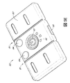
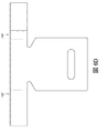
一部の実施形態では、電子サブ組立品のための支持機構またはクレードルのような作用を行う構築物を使用し得る。図19Aは、電子ユニット67の実施形態を図示する。電子ユニット67は、本明細書で説明した通り、ポンプを被覆材の流体環境から保護するために、ポンプ入口および出口保護機構をコーティングおよび/または含むことができる。図19Bは、吸収被覆材材料内部に、吸収被覆材材料502に隣接して、および/またはその上に位置し得るクレードル501の材料の実施形態を図示する。一部の実施形態では、クレードル501は、図19Bおよび19Cに図示した通り、被覆材材料502に隣接して位置付けられる。図19Cは、クレードル501に組み込まれ、吸収パッド502に隣接した電子ユニット67の実施形態を図示する。クレードルの形状および形態は、装置用の人間工学的形態の製造に有利であり得る。創傷被覆材内に組み込まれた電子クレードルの実施形態を図19B〜図19Cに示す。クレードル501で使用される電子組立品の実施形態を図19Aに示す。
In some embodiments, a structure that acts like a support mechanism or cradle for the electronic subassembly may be used. FIG. 19A illustrates an embodiment of the
クレードルは、親水性材料(例えば、ポリウレタン(PU)フォーム、セルロース系繊維)から構成し得る。一部の実施形態では、クレードル501は、吸収パッド502と密着して流体分布を容易にすることができ、従って図19B〜図19Cに図示するように貯留を防止する。一部の実施形態では、電子クレードル501は、創傷接触層(図示せず)と直接接触し得る。
The cradle may be constructed from a hydrophilic material (eg, polyurethane (PU) foam, cellulosic fibers). In some embodiments, the
クレードルは、図19Bに図示するように、電子ユニット67の構成要素を受けるためのクレードル材料501内のくぼみ、切り欠き、またはスロット503および504を含み得る。電子ユニット67は、クレードル材料501のくぼみ503および504に嵌合し得る。一部の実施形態では、クレードルは、バッテリーを受けるように形成された一つまたは複数のくぼみ503、および図19Bに図示した電子ユニットのポンプ入口およびポンプ出口機構を有するポンプを受けるような形状とされたくぼみ504を含み得る。一部の実施形態では、電子ユニットがクレードル内に収まると、電子ユニットの上部は、電子クレードル材料と同じ平面となるかそれと同じ高さプロフィールを有することができる。クレードルは、組み込まれた電子機器を備えた創傷被覆材が創傷または皮膚と接触するとき、患者の不快感を最小化するように柔らかい、または患者親和性の材料とし得る。一部の実施形態では、クレードルは、ケーシングを通る流体の流れを許容する吸収材またはウィッキング材料を含み得る。
The cradle may include indentations, cutouts or
図20A〜図20Bは、電子ユニット667および吸収パッド602に隣接し、かつ少なくとも部分的それと重なる電子クレードル601を組み込んだ、創傷被覆材600の実施形態を図示する。こうした実施形態では、クレードル601の材料は、電子ユニット667および吸収パッド602の一部分を収容するように形成される。一部の実施形態では、この構成は、吸収パッド602とクレードル601との間の密着性を提供し得る。一部の実施形態では、クレードル601および吸収パッド602は、透過またはスペーサ層605の上に位置付けられ得る。図20A〜図20Bに示すように、構成要素の相対的位置は、必要に応じて変化し得る。一部の実施形態では、クレードル601は、吸収パッド602と同じ材料で形成され得る。他の実施形態では、クレードル601は、吸収ポリウレタンフォームなどの吸収パッド602とは異なる材料で形成され得る。一部の実施形態では、クレードル601は、真空形成または熱成形プロセスを使用して形成され得る。
20A-20B illustrate an embodiment of a wound dressing 600 that incorporates an
一部の実施形態では、吸収体構成要素及び電子機器構成要素は、重なり合っているが、ずらされていてもよい。例えば、電子機器エリアの一部分が吸収エリア、例えば超吸収層に重なり合っていてもよいが、電子機器エリアが完全に吸収エリアの上にあるわけではない。そのため、電子機器エリアの一部分が吸収エリアからずらされ、緩衝透過層またはスペーサ層605の上にのみに設けられてもよい。被覆材層および電子構成要素は、吸収層および電子機器の上に位置付けられた、最下層およびカバー層(図示せず)の下に位置付けられた創傷接触層(図示せず)において、取り囲まれ得る。創傷接触層およびカバー層は、被覆材構成要素を封入する周辺部で封止され得る。一部の実施形態では、カバー層は、吸収材、クレードルおよび/または電子ユニットと直接、物理的に接触し得る。一部の実施形態では、電子カセットを参照して本明細書に記載する通り、カバー層は、例えば、穴または開口部が使用されるエリアで、電子ユニットおよび/またはカセットの一部に封止され、電子構成要素(例えば、スイッチおよび/または排出口)を収容し得る。
In some embodiments, the absorber component and the electronics component overlap, but may be offset. For example, a portion of the electronic device area may overlap an absorption area, such as a superabsorbent layer, but the electronic device area is not completely over the absorption area. Therefore, a part of the electronic device area may be shifted from the absorption area and provided only on the buffer transmission layer or the
一体化された電子機器を備えた被覆材組立品
被覆材層は、いくつかの構成において様々な材料層と組み立てられ得る。一部の実施形態では、電子ユニットは、上述のように、吸収層に隣接して創傷被覆材内に組み立てられ得る。図21A〜図21Fは、クレードル内に置かれた電子ユニットを組み込んだ創傷被覆材の一実施形態を図示する。代替的な実施形態では、図21A〜21Fを参照して説明した被覆材層は、本明細書の図5A〜図5E、図7A〜図7D、図8A〜図8C、図9A−図9D、および図10を参照して説明した通り、電子カセット内に電子ユニットを組み込み得る。こうした実施形態では、電子カセットは、図21A〜図21Fを参照して説明した電子クレードルの代わりに使用し得る。
Dressing assembly with integrated electronics The dressing layer can be assembled with various material layers in several configurations. In some embodiments, the electronic unit can be assembled into the wound dressing adjacent to the absorbent layer, as described above. 21A-21F illustrate one embodiment of a wound dressing incorporating an electronic unit placed in a cradle. In alternative embodiments, the dressing layer described with reference to FIGS. 21A-21F may be formed from FIGS. 5A-5E, 7A-7D, 8A-8C, 9A-9D, And as described with reference to FIG. 10, an electronic unit may be incorporated into the electronic cassette. In such embodiments, the electronic cassette may be used in place of the electronic cradle described with reference to FIGS. 21A-21F.
図21Aは、スペーサ層701の実施形態を示す。スペーサ層は、創傷接触層(図示せず)の上に提供され得る。創傷接触層は、本明細書で説明したように創傷と接触して配置される。
FIG. 21A shows an embodiment of a
図21A〜図21Fに示す通り、創傷被覆材層は、吸収エリア760および電子機器エリア761を含み得る。一部の実施形態では、電子機器エリア761は、電子ユニット704を含み得る。一部の実施形態では、吸収エリア760は、吸収材702を含み得、創傷エリアの上に位置付けられて、吸収材またはパッド702内の創傷からの流体を吸収し得る。図21Bおよび21Cは、スペーサ層701の吸収エリア706の上に提供された吸収層702を有するスペーサ層701の実施形態を図示する。図21B〜21Cでは、吸収エリア760のスペーサ層701が上にある吸収層702によって遮られる一方、電子機器エリア761のスペーサ層701は見ることができる。
As shown in FIGS. 21A-21F, the wound dressing layer may include an
図21Cは、電子ユニット704および創傷被覆材層から取り外されたクレードル705の実施形態を図示する。クレードル705は、クレードル内のくぼみ、切り欠き、またはスロット706を含む。くぼみ706は、電子ユニットの部分に嵌合するような形状である。くぼみ706は、図2、図3A〜図3D、および図4A〜図4Bを参照して示され説明された電子ユニット67と類似した電子ユニット704の下側の部分の形状と一致する相補的形状に成形され得る。例えば、図21C〜図21Eに示すように、くぼみ706はバッテリーおよびポンプ組立品の形状であり得る。図21D〜図21Fは、電子機器エリア761のスペーサ層701の上に位置付けられたクレードル705を有する創傷被覆材の実施形態を図示する。クレードル705は、吸収層702に隣接して位置付けられ得る。図21Fは、電子ユニット704が電子クレードル705のくぼみ706内にある創傷被覆材の実施形態を図示する。図21Fに示される被覆材層および構成要素は、スペーサ層701の下に位置付けられた創傷接触層(図示せず)において、クレードル705内の吸収層702および電子機器704の上方に位置付けられたカバー層(図示せず)で取り囲まれ得る。創傷接触層およびカバー層は、被覆材構成要素を封入する周辺部で封止され得る。
FIG. 21C illustrates an embodiment of the
図22A〜図22Cは、被覆材内に電子ユニット804およびクレードル805を組み込んだ創傷被覆材の他の実施形態を図示する。代替的な実施形態では、図22A〜22Cを参照して説明した被覆材層は、本明細書の図5A〜図5E、図7A〜図7D、図8A〜図8C、図9A〜図9D、および図10を参照して説明した通り、電子カセット内に電子ユニットを組み込み得る。こうした実施形態では、電子カセットは、図22A〜図22Cを参照して説明した電子クレードルの代わりに使用し得る。
22A-22C illustrate another embodiment of a wound dressing that incorporates an
図22Aは、スペーサ層801、吸収層802、およびクレードル805を含む創傷被覆材の実施形態を図示する。図22A〜図22Cに示すように、創傷被覆材層は、吸収エリア860と、電子機器エリア861とを含み得る。一部の実施形態では、電子機器エリア861は、電子ユニット804を含み得る。一部の実施形態では、吸収エリア860は、吸収材802を含み得、創傷エリアの上に位置付けられて、吸収材またはパッド802内の創傷からの流体を吸収し得る。
FIG. 22A illustrates an embodiment of a wound dressing that includes a
図22A〜図22Cに示す吸収層802は、吸収エリア860および電子機器エリア861のスペーサ層801の上方に位置付けられ、被覆材の長さにわたる。クレードル805は、電子機器エリア861の吸収層802の上方に位置付けられ得る。図22Aは、図21A〜図21Fを参照して本明細書で説明したくぼみと類似したクレードル805のくぼみ806を図示する。図22Bおよび図22Cは、クレードルのくぼみ806内に位置する電子ユニット804を図示する。図22Bおよび図22Cに示される被覆材層および構成要素は、スペーサ層801の下に位置付けられた創傷接触層(図示せず)において、クレードル805内の吸収層802および電子機器804の上方に位置付けられたカバー層(図示せず)で取り囲まれ得る。創傷接触層およびカバー層は、被覆材構成要素を封入する周辺部で封止され得る。
The
図23は、スペーサ層901の全長にわたって提供される吸収層902を図示する。図23に示すように、創傷被覆材層は、吸収エリア960と、電子機器エリア961とを含み得る。一部の実施形態では、電子機器エリア961は、電子ユニットを含み得る。一部の実施形態では、吸収エリア960は、吸収材902を含み得、創傷エリアの上に位置付けられて、吸収材またはパッド902内の創傷からの流体を吸収し得る。吸収層は、電子機器エリア961内に位置する吸収層902の一部にある一つのくぼみ、切り欠き、またはスロット907を有する。スペーサ層901は、吸収層902のくぼみ907内に見える。一部の実施形態では、図23に示すように、吸収材902は、被覆材の長さにわたり、吸収材902の単一の開口部907を含み得る。一部の実施形態では、本明細書に記載の電子クレードルまたは電子カセットは、被覆材の吸収材または吸収層902の単一の開口部907内に配置され得る。こうした実施形態では、電子ユニットは、本明細書に記載の電子クレードルまたは電子カセット内に位置付けられ得る。図23に示される被覆材層および構成要素は、スペーサ層901の下に位置付けられた創傷接触層(図示せず)において、吸収層902および電子クレードルまたはカセットの上方に位置付けられたカバー層(図示せず)で取り囲まれ得る。創傷接触層およびカバー層は、被覆材構成要素を封入する周辺部で封止され得る。
FIG. 23 illustrates an
図24は、クレードル1005内に置かれた電子ユニットを組み込んだ創傷被覆材の一実施形態を図示する。代替的な実施形態では、図24を参照して説明した被覆材層は、本明細書の図5A〜図5E、図7A〜図7D、図8A〜図8C、図9A〜図9D、および図10を参照して説明した通り、電子カセット内に電子ユニットを組み込み得る。こうした実施形態では、電子カセットは、図24を参照して説明した電子クレードルの代わりに使用し得る。図24に示すように、創傷被覆材層は、吸収エリア1060と、電子機器エリア1061とを含み得る。一部の実施形態では、電子機器エリア1061は、電子ユニット1004および電子クレードル1005を含み得る。一部の実施形態では、吸収エリア1060は、吸収材1002を含み得、創傷エリアの上に位置付けられて、吸収材またはパッド1002内の創傷からの流体を吸収し得る。図24は、クレードル1005および電子ユニット1004に隣接して位置付けられたスペーサ層1001および吸収層1002を図示する。図24に図示した被覆材構成は、図21A〜図21Fを参照して説明した被覆材と類似する。しかしながら、図24に示すスペーサ層1001は、被覆材の全長に延在しない。代わりに、スペーサ層1001はクレードル1005の端部にのみ延在し、クレードルは下にある創傷接触層1006と直接接触するように位置付けられる。図24に示すように、スペーサ層1001および吸収層1002は、吸収エリア1060内に位置付けられ、電子機器エリア1061まで延在しない。クレードル1005および電子ユニット1004は、電子機器エリア1061内に位置付けられる。図24は、創傷接触層1006を有するがカバー層のない状態の創傷被覆材および電子機器エリアの層を図示する。図24に示される被覆材層および構成要素は、スペーサ層およびクレードルの下に位置付けられた創傷接触層1006において、およびクレードル1005内の吸収層および電子機器1004の上方に位置付けられたカバー層(図示せず)で封入され得る。創傷接触層1006およびカバー層は、被覆材構成要素を取り囲む周辺部で封止され得る。
FIG. 24 illustrates one embodiment of a wound dressing incorporating an electronic unit placed in the
図25A〜図25Bは、創傷接触層(図示せず)とカバー層1110との間に被覆材層を封入した、組み立てられた創傷被覆材の一実施形態を図示する。図25A〜図25Bに示すように、創傷被覆材層は、吸収エリア1160と、電子機器エリア1161とを含み得る。一部の実施形態では、電子機器エリア1161は、電子ユニット1104および電子クレードル1105を含み得る。一部の実施形態では、吸収エリア1160は、吸収材1102を含み得、創傷エリアの上に位置付けられて、吸収材またはパッド1102内の創傷からの流体を吸収し得る。創傷被覆材は、図25Aに図示したようなスペーサ層1101を含み得る。図25A〜図25Bに示される被覆材層および構成要素は、スペーサ層1101の下に位置付けられた創傷接触層(図示せず)において、クレードル1105内の吸収層1102および電子ユニット1104の上方に位置付けられたカバー層1110で取り囲まれ得る。創傷接触層およびカバー層1110は、被覆材構成要素を取り囲む周辺部で封止され得る。
FIGS. 25A-25B illustrate one embodiment of an assembled wound dressing with a dressing layer encapsulated between the wound contact layer (not shown) and the
図26は、図25A〜25Bに示した被覆材と類似した組み立てられた創傷被覆材の実施形態を図示する。しかしながら、図26の創傷被覆材は、被覆材層の上およびカバー層1210の下に位置する追加的なマスキングまたは隠蔽層1208を含む。図26に示すように、創傷被覆材層は、吸収エリア1260と、電子機器エリア1261とを含み得る。一部の実施形態では、電子機器エリア1261は、電子ユニット1204を含み得る。一部の実施形態では、吸収エリア1260は、吸収材を含み得、創傷エリアの上に位置付けられて、吸収材またはパッド内の創傷からの流体を吸収し得る。一部の実施形態では、マスキングまたは隠蔽層1208は、吸収層および電子機器1204の上方、およびカバー層1210の下方に位置付けられ得る。一部の実施形態では、マスキングまたは隠蔽層1208は、図26に示す通り、マスキングまたは遮蔽層1208の下に電子機器1204が見えるようにする開口部1209を含み得る。一部の実施形態では、マスキングまたは隠蔽層1208は、創傷滲出液またはその他の流体が創傷被覆材の上から見えないようにする不透明材料であり得る。一部の実施形態では、マスキング層または遮蔽層は、吸収エリア1260および電子機器エリア1261の全長にわたり得る。一部の実施形態では、マスキングまたは遮蔽層は、スペーサ層、吸収層、および電子ユニット、クレードル、またはカセットよりも大きな周辺部を有し得、図26に示すように、吸収材および電子ユニット、クレードル、またはカセットの縁を超えて覆うことができる。
FIG. 26 illustrates an embodiment of an assembled wound dressing similar to the dressing shown in FIGS. However, the wound dressing of FIG. 26 includes an additional masking or concealing
一部の実施形態では、吸収体構成要素及び電子機器構成要素は、重なり合っているが、ずらされていてもよい。例えば、電子機器エリアの一部分が吸収エリア、例えば超吸収層に重なり合っていてもよいが、電子機器エリアが完全に吸収エリアの上にあるわけではない。そのため、電子機器エリアの一部分が吸収エリアからずらされ、緩衝スペーサ層の上にのみに設けられてもよい。 In some embodiments, the absorber component and the electronics component overlap, but may be offset. For example, a portion of the electronic device area may overlap an absorption area, such as a superabsorbent layer, but the electronic device area is not completely over the absorption area. Therefore, a part of the electronic device area may be shifted from the absorption area and provided only on the buffer spacer layer.
(あらゆる添付資料、特許請求の範囲、要約書、および図面を含む)本明細書において開示されるすべての特徴、及び/又はそのように開示されるあらゆる方法もしくはプロセスのすべてのステップは、そのような特徴及び/又はステップのうち少なくともいくつかが相互に排他的である組み合わせを除いて、任意の組み合わせで組み合わされてよい。開示対象は、いかなる前述の実施形態の詳細にも制限されない。開示は、本明細書(添付の特許請求の範囲、要約書および図面のいずれをも含む)に開示する特徴のいずれか新規のもの、もしくはいずれか新規の組み合わせ、または同様に開示するいずれの方法もしくは過程のステップのいずれか新規のもの、もしくはいずれか新規の組み合わせに及ぶ。 All features disclosed herein (including any attachments, claims, abstracts, and drawings) and / or all steps of any method or process so disclosed are Combinations may be made in any combination except combinations where at least some of the features and / or steps are mutually exclusive. The disclosed subject matter is not limited to the details of any foregoing embodiments. The disclosure includes any novel feature, any novel combination of features disclosed herein (including any of the appended claims, abstracts and drawings), or any method disclosed therein Or any new step in the process, or any new combination.
「し得る(can)」、「できる(could)」、「可能性がある(might)」、または「場合がある(may)」などの条件付き言い回しは、別途具体的に記載されない限り、または使用される文脈の範囲内で別途解釈されない限り、一定の実施形態が、特定の特徴、要素、またはステップを含む一方で、他の実施形態は含まないということの伝達を意図するのが通例である。したがって、こうした条件付き言い回しは、特徴、要素、またはステップが一つまたは複数の実施形態に多少なりとも必要とされるという示唆、またはこれらの特徴、要素、もしくはステップが特定の任意の実施形態に含まれているかどうか、もしくは該実施形態で実施されるべきかどうかを、ユーザ入力または命令の有無にかかわらず決定するためのロジックが、一つまたは複数の実施形態に必然的に含まれているという示唆を必ずしも意図するものではない。「備える(comprising)」、「含む(including)」、及び「有する(having)」などの用語は、同義語であり、包含的に非限定様式で用いられ、追加の要素、特徴、行為、及び動作などを排除するものではない。また、用語「または(or)」は、包括的な意味で(排他的な意味ではなく)用いられることで、例えば要素の列記をつなぐのに使用される場合、列記の要素のうちの一つ、一部、または全てを意味することになる。同様に、「および(and)/または(or)」という用語は、二つ以上の項目の列挙に関して、言葉の以下の解釈のすべて:列挙内の項目も任意の一つ、列挙内のすべての項目、および列挙内の項目の任意の組み合わせ、を網羅する。さらに、用語「各々」は、本明細書で使用される場合、通常の意味を有するのに加えて、用語「各々」が適用されている一連の要素の任意のサブセットも意味し得る。さらに、本明細書で使用される場合、「本明細書での(herein)」、「上記(above)」、「下記(below)」および類似する言葉は、本出願で使用される場合、本明細書の全体を指し、本明細書の特定の部分を指すものではないことを意味する。 Conditional phrases such as “can”, “could”, “might”, or “may” are, unless specifically stated otherwise, or Unless otherwise interpreted within the context of use, it is typically intended to convey that certain embodiments include certain features, elements, or steps, but not other embodiments. is there. Accordingly, such conditional phrases may imply that features, elements, or steps are required in any way in one or more embodiments, or these features, elements, or steps may be in any particular embodiment. One or more embodiments necessarily include logic to determine whether it is included or should be implemented in that embodiment, with or without user input or instructions. It is not necessarily intended to suggest. Terms such as “comprising”, “including”, and “having” are synonymous and are used in an inclusive and non-limiting manner to describe additional elements, features, acts, and It does not exclude operations. Also, the term “or” is used in a comprehensive sense (rather than an exclusive meaning), eg, when used to connect a list of elements, one of the listed elements. , Part or all. Similarly, the term “and” or “or” relates to the enumeration of two or more items in all of the following interpretations of the words: any item in the enumeration is any one, all in the enumeration Covers items, and any combination of items in an enumeration. Further, the term “each”, as used herein, may mean any subset of a series of elements to which the term “each” is applied, in addition to having its ordinary meaning. Further, as used herein, “herein”, “above”, “below” and like terms are used in this application to It is meant to refer to the entire specification and not a specific part of the specification.
語句「X、Y、およびZのうちの少なくとも一つ」などの連言的言い回しは、別途具体的に記載されない限り、ある項目や用語などが、Xか、Yか、Zのいずれかであり得ることを示唆するのに一般的に用いられる文脈によって、別途解釈されるものである。したがって、こうした連言的言い回しは、特定の実施形態が、少なくとも一つのXと、少なくとも一つYと、少なくとも一つのZとを含むことを必要とするという示唆を必ずしも意図するものではない。 Conjunctive phrases such as the phrase “at least one of X, Y, and Z” means that an item or term is either X, Y, or Z unless specifically stated otherwise. It is to be construed differently depending on the context that is commonly used to suggest gain. Thus, these conjunctive phrases are not necessarily intended to suggest that particular embodiments need to include at least one X, at least one Y, and at least one Z.
本明細書で使用される「およそ」、「約」、「概して」、および「実質的に」という用語などの、本明細書で使用される程度を表す言い回しは、所望の機能を依然として果たすかまたは所望の結果をもたらす所定の値、量、または特性に近い値、量、または特性を表すものである。例えば、「およそ」、「約」、「概して」、及び「実質的に」という用語は、所定の量の10%未満以内、5%未満以内、1%未満以内、0.1%未満以内、及び0.01%未満以内の量を意味し得る。別の例として、一定の実施形態において、「概して平行」及び「実質的に平行」という用語は、丁度平行である状態から15度以下、10度以下、5度以下、3度以下、1度以下、または0.1度以下ずれている値、量、または特性を意味する。 As used herein, phrases such as “approximately”, “about”, “generally”, and “substantially” used to describe the extent used herein still perform the desired function. Alternatively, it represents a value, amount, or characteristic that approximates a predetermined value, quantity, or characteristic that produces a desired result. For example, the terms “approximately”, “about”, “generally”, and “substantially” are within less than 10%, less than 5%, less than 1%, less than 0.1% of a given amount, And may mean an amount within less than 0.01%. As another example, in certain embodiments, the terms “generally parallel” and “substantially parallel” are just 15 degrees or less, 10 degrees or less, 5 degrees or less, 3 degrees or less, 1 degree from the state of being exactly parallel. Means a value, amount, or characteristic that is less than or less than 0.1 degrees below.
本開示に記載する実装に対する様々な変形は、当業者には容易に明らかとなってもよく、本明細書に定義する全体的な原理は、本開示の精神または範囲を逸脱することなく、他の実装に適用されてもよい。それゆえ、開示は、本明細書に示す実装に限定することは意図していないが、本明細書に記載する原理および特徴と一致する、最も広い範囲が与えられるべきである。開示のある実施形態は、以下に列挙する、または後に提示する請求項の組に網羅される。
Various modifications to the implementations described in this disclosure may be readily apparent to those skilled in the art, and the overall principles defined herein may be modified without departing from the spirit or scope of this disclosure. May be applied to the implementation of The disclosure is therefore not intended to be limited to the implementations shown herein but is to be accorded the widest scope consistent with the principles and features described herein. Certain embodiments of the disclosure are covered by the set of claims listed below or presented later.
Claims (40)
創傷と接触して配置されるよう構成される創傷接触層と、
前記創傷接触層上の第一エリアであって、
スペーサ層、および
前記スペーサ層上の吸収層を含む、第一エリアと、
電子カセットを備える前記創傷接触層の上の第二エリアであって、前記電子カセットが陰圧源および/またはケーシングによって囲まれた電子構成要素を備え、前記第一エリアが前記第二エリアに隣接して位置付けられ、
前記ケーシングが、前記陰圧源および/または電子構成要素を囲み、前記第一エリアと第二エリアとの間の流体連通を可能にするように構成される、第二エリアと、
前記創傷接触層と、前記第一エリアと、前記第二エリアとを被覆し、それらの上で封止を形成するよう構成されるカバー層と、を含む、創傷被覆材装置。 A wound dressing device,
A wound contact layer configured to be placed in contact with the wound;
A first area on the wound contact layer,
A first area comprising a spacer layer, and an absorbent layer on the spacer layer;
A second area on the wound contact layer comprising an electronic cassette, the electronic cassette comprising an electronic component surrounded by a negative pressure source and / or a casing, wherein the first area is adjacent to the second area Is positioned as
A second area, wherein the casing surrounds the negative pressure source and / or electronic component and is configured to allow fluid communication between the first area and the second area;
A wound dressing device comprising: a wound layer configured to cover the wound contact layer, the first area, and the second area and form a seal thereon.
創傷と接触して配置されるよう構成される創傷接触層と、
前記創傷接触層上の第一エリアであって、
スペーサ層、および
前記スペーサ層上の吸収層を含む、第一エリアと、
電子ユニットを備える前記創傷接触層上の第二エリアであって、前記電子ユニットが陰圧源および/または電子構成要素を備え、前記第一エリアが前記第二エリアに隣接して位置付けられ、
前記第二エリアが、前記第一エリアと第二エリアとの間の流体連通を可能にするように構成されるクレードルを備え、前記クレードルが、前記電子ユニットの一部分を受けるように構成されるくぼみを含む、第二エリアと、
前記創傷接触層と、前記第一エリアと、前記第二エリアとを被覆し、それらの上で封止を形成するよう構成されるカバー層と、を含む、創傷被覆材装置。 A wound dressing device,
A wound contact layer configured to be placed in contact with the wound;
A first area on the wound contact layer,
A first area comprising a spacer layer, and an absorbent layer on the spacer layer;
A second area on the wound contact layer comprising an electronic unit, the electronic unit comprising a negative pressure source and / or an electronic component, wherein the first area is positioned adjacent to the second area;
The second area comprises a cradle configured to allow fluid communication between the first area and the second area, wherein the cradle is configured to receive a portion of the electronic unit; Including the second area,
A wound dressing device comprising: a wound layer configured to cover the wound contact layer, the first area, and the second area and form a seal thereon.
近位の創傷に面する面および遠位面を含む創傷接触層であって、前記創傷に面する面が創傷と接触して位置付けられるように構成される創傷接触層と、
近位の創傷に面する面および遠位面を含むスペーサ層であって、前記創傷接触層の前記遠位面の上に位置付けられるスペーサ層と、
吸収層を含む前記スペーサ層上の第一エリアと、
電子ユニットを備える前記スペーサ層上の第二エリアであって、前記電子ユニットが陰圧源および/または電子構成要素を備え、前記第一エリアが前記第二エリアに隣接して位置付けられ、
前記スペーサ層上の前記第二エリアが、前記第一エリアと第二エリアとの間の流体連通を可能にするように構成されるクレードルを備え、前記クレードルが、前記電子ユニットを受けるように構成されるくぼみを含む、第二エリアと、
前記創傷接触層と、前記スペーサ層と、前記第一エリアと、前記第二エリアとを覆い、その上で封止を形成するよう構成されたカバー層と、を含む、創傷被覆材装置。 A wound dressing device,
A wound contact layer comprising a proximal wound facing surface and a distal surface, wherein the wound contact layer is configured such that the wound facing surface is positioned in contact with the wound;
A spacer layer comprising a proximal wound facing surface and a distal surface, the spacer layer positioned on the distal surface of the wound contact layer;
A first area on the spacer layer including an absorbent layer;
A second area on the spacer layer comprising an electronic unit, the electronic unit comprising a negative pressure source and / or an electronic component, wherein the first area is positioned adjacent to the second area;
The second area on the spacer layer comprises a cradle configured to allow fluid communication between the first area and the second area, the cradle configured to receive the electronic unit A second area, including indentations to be made,
A wound dressing device comprising: a wound layer configured to cover the wound contact layer, the spacer layer, the first area, and the second area and form a seal thereon.
近位の創傷に面する面および遠位面を含む創傷接触層であって、前記近位の創傷に面する面が創傷と接触して位置付けられるように構成される創傷接触層と、
近位の創傷に面する面および遠位面を含むスペーサ層であって、前記創傷接触層の前記遠位面の上に位置付けられるスペーサ層と、
近位の創傷に面する面および遠位面を含む吸収層であって、前記スペーサ層の前記遠位面上に位置付けられる吸収層と、
陰圧源および/または電子構成要素を備える電子ユニットと、
前記吸収層の前記遠位面上に位置付けられ、前記吸収層と前記電子ユニットとの間の流体連通を可能とするように構成されるクレードルであって、前記電子ユニットを受けるように構成されるくぼみを含むクレードルと、
前記創傷接触層、前記スペーサ層、前記吸収層、前記クレードルおよび電子ユニットを覆い、それらの上で封止を形成するように構成されるカバー層と、を含む、創傷被覆材装置。 A wound dressing device,
A wound contact layer comprising a proximal wound facing surface and a distal surface, the wound contact layer configured such that the proximal wound facing surface is positioned in contact with the wound;
A spacer layer comprising a proximal wound facing surface and a distal surface, the spacer layer positioned on the distal surface of the wound contact layer;
An absorbent layer comprising a proximal wound-facing surface and a distal surface, the absorbent layer positioned on the distal surface of the spacer layer;
An electronic unit comprising a negative pressure source and / or electronic components;
A cradle positioned on the distal surface of the absorbent layer and configured to allow fluid communication between the absorbent layer and the electronic unit, the cradle configured to receive the electronic unit A cradle containing a depression,
A wound dressing device comprising: a wound layer covering the wound contact layer, the spacer layer, the absorbent layer, the cradle and the electronic unit and configured to form a seal thereon.
近位の創傷に面する面および遠位面を含む創傷接触層であって、前記創傷に面する面が創傷と接触して位置付けられるように構成される創傷接触層と、
前記創傷接触層上の前記遠位面上の第一エリアであって、
スペーサ層、および
前記スペーサ層上の吸収層を含む、第一エリアと、
電子ユニットを備える前記創傷接触層の前記遠位面上の第二エリアであって、前記電子ユニットが陰圧源および/または電子構成要素を備え、前記第一エリアが前記第二エリアに隣接して位置付けられ、
前記第二エリアが前記創傷接触層上に直接位置付けられるクレードルを備え、前記クレードルが前記第一エリアと第二エリアとの間の流体連通を可能にするように構成され、前記クレードルが、前記電子ユニットを受けるように構成されるくぼみを含む、第二エリアと、
前記創傷接触層と、前記第一エリアと、前記第二エリアとを被覆し、それらの上で封止を形成するよう構成されるカバー層と、を含む、創傷被覆材装置。 A wound dressing device,
A wound contact layer comprising a proximal wound facing surface and a distal surface, wherein the wound contact layer is configured such that the wound facing surface is positioned in contact with the wound;
A first area on the distal surface on the wound contact layer,
A first area comprising a spacer layer, and an absorbent layer on the spacer layer;
A second area on the distal surface of the wound contact layer comprising an electronic unit, the electronic unit comprising a negative pressure source and / or an electronic component, wherein the first area is adjacent to the second area. Positioned,
The second area comprises a cradle positioned directly on the wound contact layer, the cradle being configured to allow fluid communication between the first area and the second area, the cradle comprising the electronic A second area including a recess configured to receive the unit;
A wound dressing device comprising: a wound layer configured to cover the wound contact layer, the first area, and the second area and form a seal thereon.
38. The wound dressing device of claim 37, wherein the negative pressure source inlet protection mechanism comprises a hydrophobic material configured to prevent fluid from entering the negative pressure source.
Applications Claiming Priority (7)
| Application Number | Priority Date | Filing Date | Title |
|---|---|---|---|
| US201662402382P | 2016-09-30 | 2016-09-30 | |
| US201662402298P | 2016-09-30 | 2016-09-30 | |
| US201662402146P | 2016-09-30 | 2016-09-30 | |
| US62/402,146 | 2016-09-30 | ||
| US62/402,298 | 2016-09-30 | ||
| US62/402,382 | 2016-09-30 | ||
| PCT/EP2017/074755 WO2018060412A1 (en) | 2016-09-30 | 2017-09-29 | Negative pressure wound treatment apparatuses and methods with integrated electronics |
Publications (2)
| Publication Number | Publication Date |
|---|---|
| JP2019528957A true JP2019528957A (en) | 2019-10-17 |
| JP2019528957A5 JP2019528957A5 (en) | 2020-10-22 |
Family
ID=59982383
Family Applications (1)
| Application Number | Title | Priority Date | Filing Date |
|---|---|---|---|
| JP2019516606A Pending JP2019528957A (en) | 2016-09-30 | 2017-09-29 | Negative pressure wound treatment apparatus and method with integrated electronics |
Country Status (5)
| Country | Link |
|---|---|
| US (1) | US20190282737A1 (en) |
| EP (1) | EP3519000A1 (en) |
| JP (1) | JP2019528957A (en) |
| AU (1) | AU2017336305B2 (en) |
| WO (1) | WO2018060412A1 (en) |
Families Citing this family (18)
| Publication number | Priority date | Publication date | Assignee | Title |
|---|---|---|---|---|
| CA3016484A1 (en) | 2016-03-07 | 2017-09-14 | Smith & Nephew Plc | Wound treatment apparatuses and methods with negative pressure source integrated into wound dressing |
| CN114469523A (en) | 2016-04-26 | 2022-05-13 | 史密夫及内修公开有限公司 | Wound dressing and method for use with an integrated negative pressure source having a fluid intrusion inhibiting feature |
| US11096831B2 (en) | 2016-05-03 | 2021-08-24 | Smith & Nephew Plc | Negative pressure wound therapy device activation and control |
| EP3452130B1 (en) | 2016-05-03 | 2021-12-01 | Smith & Nephew plc | Optimizing power transfer to negative pressure sources in negative pressure therapy systems |
| AU2017259003B2 (en) | 2016-05-03 | 2022-09-22 | Smith & Nephew Plc | Systems and methods for driving negative pressure sources in negative pressure therapy systems |
| EP3503857B1 (en) | 2016-08-25 | 2024-04-17 | Smith & Nephew plc | Absorbent negative pressure wound therapy dressing |
| WO2018060417A1 (en) | 2016-09-30 | 2018-04-05 | Smith & Nephew Plc | Negative pressure wound treatment apparatuses and methods with integrated electronics |
| US11123471B2 (en) | 2017-03-08 | 2021-09-21 | Smith & Nephew Plc | Negative pressure wound therapy device control in presence of fault condition |
| CN110612131B (en) | 2017-05-09 | 2023-05-16 | 史密夫及内修公开有限公司 | Redundant control for negative pressure wound therapy system |
| CN111065424A (en) | 2017-09-13 | 2020-04-24 | 史密夫及内修公开有限公司 | Negative pressure wound therapy apparatus with integrated electronics and method |
| GB201718070D0 (en) | 2017-11-01 | 2017-12-13 | Smith & Nephew | Negative pressure wound treatment apparatuses and methods with integrated electronics |
| GB201718072D0 (en) | 2017-11-01 | 2017-12-13 | Smith & Nephew | Negative pressure wound treatment apparatuses and methods with integrated electronics |
| GB201718054D0 (en) | 2017-11-01 | 2017-12-13 | Smith & Nephew | Sterilization of integrated negative pressure wound treatment apparatuses and sterilization methods |
| EP3703632B1 (en) | 2017-11-01 | 2024-04-03 | Smith & Nephew plc | Negative pressure wound treatment apparatuses and methods with integrated electronics |
| WO2020005577A1 (en) * | 2018-06-28 | 2020-01-02 | Kci Licensing, Inc. | Distributed negative pressure wound therapy system incorporating an absorbent dressing and piezo-electric pump |
| USD898925S1 (en) | 2018-09-13 | 2020-10-13 | Smith & Nephew Plc | Medical dressing |
| GB201903774D0 (en) | 2019-03-20 | 2019-05-01 | Smith & Nephew | Negative pressure wound treatment apparatuses and methods with integrated electronics |
| USD955566S1 (en) * | 2020-07-01 | 2022-06-21 | Zealand Pharma A/S | Medicament delivery device |
Citations (1)
| Publication number | Priority date | Publication date | Assignee | Title |
|---|---|---|---|---|
| JP2015514451A (en) * | 2012-03-12 | 2015-05-21 | スミス アンド ネフュー ピーエルシーSmith & Nephew Public Limited Company | Pressure reducing apparatus and method |
Family Cites Families (14)
| Publication number | Priority date | Publication date | Assignee | Title |
|---|---|---|---|---|
| GB0508528D0 (en) | 2005-04-27 | 2005-06-01 | Smith & Nephew | SAI with macrostress |
| US7753894B2 (en) | 2004-04-27 | 2010-07-13 | Smith & Nephew Plc | Wound cleansing apparatus with stress |
| CN101257875A (en) * | 2005-09-06 | 2008-09-03 | 泰科保健集团有限合伙公司 | Self contained wound dressing with micropump |
| MX2010005553A (en) * | 2007-11-21 | 2010-06-01 | Smith & Nephew | Wound dressing. |
| US9061095B2 (en) | 2010-04-27 | 2015-06-23 | Smith & Nephew Plc | Wound dressing and method of use |
| EP2422887A1 (en) * | 2010-08-27 | 2012-02-29 | Oticon A/S | A method of coating a surface with a water and oil repellant polymer layer |
| KR20140044906A (en) | 2011-07-14 | 2014-04-15 | 스미쓰 앤드 네퓨 피엘씨 | Wound dressing and method of treatment |
| US9084845B2 (en) * | 2011-11-02 | 2015-07-21 | Smith & Nephew Plc | Reduced pressure therapy apparatuses and methods of using same |
| HUE047600T2 (en) | 2012-05-23 | 2020-04-28 | Smith & Nephew | Apparatuses for negative pressure wound therapy |
| CN104661626B (en) | 2012-08-01 | 2018-04-06 | 史密夫及内修公开有限公司 | Wound dressing |
| ES2625709T3 (en) | 2012-08-01 | 2017-07-20 | Smith & Nephew Plc. | Wound dressing |
| SG11201704255WA (en) * | 2014-12-22 | 2017-07-28 | Smith & Nephew | Negative pressure wound therapy apparatus and methods |
| CN113367890B (en) * | 2015-04-27 | 2023-02-21 | 史密夫及内修公开有限公司 | Pressure reducing device |
| CN114469523A (en) * | 2016-04-26 | 2022-05-13 | 史密夫及内修公开有限公司 | Wound dressing and method for use with an integrated negative pressure source having a fluid intrusion inhibiting feature |
-
2017
- 2017-09-29 EP EP17777257.1A patent/EP3519000A1/en active Pending
- 2017-09-29 WO PCT/EP2017/074755 patent/WO2018060412A1/en unknown
- 2017-09-29 US US16/338,386 patent/US20190282737A1/en active Pending
- 2017-09-29 AU AU2017336305A patent/AU2017336305B2/en active Active
- 2017-09-29 JP JP2019516606A patent/JP2019528957A/en active Pending
Patent Citations (1)
| Publication number | Priority date | Publication date | Assignee | Title |
|---|---|---|---|---|
| JP2015514451A (en) * | 2012-03-12 | 2015-05-21 | スミス アンド ネフュー ピーエルシーSmith & Nephew Public Limited Company | Pressure reducing apparatus and method |
Also Published As
| Publication number | Publication date |
|---|---|
| EP3519000A1 (en) | 2019-08-07 |
| AU2017336305B2 (en) | 2023-01-19 |
| AU2017336305A1 (en) | 2019-04-11 |
| US20190282737A1 (en) | 2019-09-19 |
| WO2018060412A1 (en) | 2018-04-05 |
Similar Documents
| Publication | Publication Date | Title |
|---|---|---|
| JP2019528957A (en) | Negative pressure wound treatment apparatus and method with integrated electronics | |
| US11701265B2 (en) | Negative pressure wound treatment apparatuses and methods with integrated electronics | |
| US20230248578A1 (en) | Negative pressure wound treatment apparatuses and methods with integrated electronics | |
| US11497653B2 (en) | Negative pressure wound treatment apparatuses and methods with integrated electronics | |
| US20230240898A1 (en) | Negative pressure wound treatment apparatuses and methods with integrated electronics | |
| JP6911043B2 (en) | Wound healing devices and methods in which the negative pressure source is integrated within the wound dressing | |
| US11554203B2 (en) | Negative pressure wound treatment apparatuses and methods with integrated electronics | |
| US11992392B2 (en) | Negative pressure wound treatment apparatuses and methods with integrated electronics |
Legal Events
| Date | Code | Title | Description |
|---|---|---|---|
| RD03 | Notification of appointment of power of attorney |
Free format text: JAPANESE INTERMEDIATE CODE: A7423 Effective date: 20190408 |
|
| RD04 | Notification of resignation of power of attorney |
Free format text: JAPANESE INTERMEDIATE CODE: A7424 Effective date: 20190416 |
|
| A521 | Request for written amendment filed |
Free format text: JAPANESE INTERMEDIATE CODE: A523 Effective date: 20200909 |
|
| A621 | Written request for application examination |
Free format text: JAPANESE INTERMEDIATE CODE: A621 Effective date: 20200909 |
|
| A977 | Report on retrieval |
Free format text: JAPANESE INTERMEDIATE CODE: A971007 Effective date: 20210608 |
|
| A131 | Notification of reasons for refusal |
Free format text: JAPANESE INTERMEDIATE CODE: A131 Effective date: 20210621 |
|
| A521 | Request for written amendment filed |
Free format text: JAPANESE INTERMEDIATE CODE: A523 Effective date: 20210915 |
|
| A131 | Notification of reasons for refusal |
Free format text: JAPANESE INTERMEDIATE CODE: A131 Effective date: 20211129 |
|
| A521 | Request for written amendment filed |
Free format text: JAPANESE INTERMEDIATE CODE: A523 Effective date: 20211224 |
|
| A02 | Decision of refusal |
Free format text: JAPANESE INTERMEDIATE CODE: A02 Effective date: 20220523 |
|
| A521 | Request for written amendment filed |
Free format text: JAPANESE INTERMEDIATE CODE: A523 Effective date: 20220921 |
|
| C60 | Trial request (containing other claim documents, opposition documents) |
Free format text: JAPANESE INTERMEDIATE CODE: C60 Effective date: 20220921 |
|
| A911 | Transfer to examiner for re-examination before appeal (zenchi) |
Free format text: JAPANESE INTERMEDIATE CODE: A911 Effective date: 20220928 |
|
| C21 | Notice of transfer of a case for reconsideration by examiners before appeal proceedings |
Free format text: JAPANESE INTERMEDIATE CODE: C21 Effective date: 20221003 |
|
| A912 | Re-examination (zenchi) completed and case transferred to appeal board |
Free format text: JAPANESE INTERMEDIATE CODE: A912 Effective date: 20221202 |
|
| C211 | Notice of termination of reconsideration by examiners before appeal proceedings |
Free format text: JAPANESE INTERMEDIATE CODE: C211 Effective date: 20221212 |
|
| C22 | Notice of designation (change) of administrative judge |
Free format text: JAPANESE INTERMEDIATE CODE: C22 Effective date: 20230116 |
|
| C23 | Notice of termination of proceedings |
Free format text: JAPANESE INTERMEDIATE CODE: C23 Effective date: 20230403 |