JP2019524200A - Selection of catheter type - Google Patents
Selection of catheter type Download PDFInfo
- Publication number
- JP2019524200A JP2019524200A JP2018568242A JP2018568242A JP2019524200A JP 2019524200 A JP2019524200 A JP 2019524200A JP 2018568242 A JP2018568242 A JP 2018568242A JP 2018568242 A JP2018568242 A JP 2018568242A JP 2019524200 A JP2019524200 A JP 2019524200A
- Authority
- JP
- Japan
- Prior art keywords
- vascular
- intravascular device
- determined
- path
- catheter
- Prior art date
- Legal status (The legal status is an assumption and is not a legal conclusion. Google has not performed a legal analysis and makes no representation as to the accuracy of the status listed.)
- Ceased
Links
- 230000002792 vascular Effects 0.000 claims abstract description 152
- 238000003384 imaging method Methods 0.000 claims abstract description 59
- 238000000034 method Methods 0.000 claims abstract description 56
- 238000012545 processing Methods 0.000 claims abstract description 38
- 238000004590 computer program Methods 0.000 claims abstract description 22
- 230000037361 pathway Effects 0.000 claims description 39
- 210000005166 vasculature Anatomy 0.000 claims description 22
- 239000000463 material Substances 0.000 description 15
- 210000004204 blood vessel Anatomy 0.000 description 9
- 230000015654 memory Effects 0.000 description 8
- 238000010586 diagram Methods 0.000 description 5
- 238000013152 interventional procedure Methods 0.000 description 5
- 230000011218 segmentation Effects 0.000 description 5
- 239000011148 porous material Substances 0.000 description 4
- 238000013459 approach Methods 0.000 description 3
- 210000001367 artery Anatomy 0.000 description 3
- 238000005452 bending Methods 0.000 description 3
- 238000002591 computed tomography Methods 0.000 description 3
- 201000010099 disease Diseases 0.000 description 3
- 208000037265 diseases, disorders, signs and symptoms Diseases 0.000 description 3
- 239000003814 drug Substances 0.000 description 3
- 229940079593 drug Drugs 0.000 description 3
- 238000003780 insertion Methods 0.000 description 3
- 230000037431 insertion Effects 0.000 description 3
- 230000008569 process Effects 0.000 description 3
- 206010028980 Neoplasm Diseases 0.000 description 2
- 208000007536 Thrombosis Diseases 0.000 description 2
- 238000004458 analytical method Methods 0.000 description 2
- 238000002583 angiography Methods 0.000 description 2
- 230000008901 benefit Effects 0.000 description 2
- 230000008859 change Effects 0.000 description 2
- 230000001419 dependent effect Effects 0.000 description 2
- 230000006870 function Effects 0.000 description 2
- 238000011065 in-situ storage Methods 0.000 description 2
- 230000004044 response Effects 0.000 description 2
- 238000003860 storage Methods 0.000 description 2
- 238000001356 surgical procedure Methods 0.000 description 2
- 230000003936 working memory Effects 0.000 description 2
- 206010002329 Aneurysm Diseases 0.000 description 1
- 238000012935 Averaging Methods 0.000 description 1
- 208000009087 False Aneurysm Diseases 0.000 description 1
- 206010057469 Vascular stenosis Diseases 0.000 description 1
- 210000003484 anatomy Anatomy 0.000 description 1
- 230000000740 bleeding effect Effects 0.000 description 1
- 239000008280 blood Substances 0.000 description 1
- 210000004369 blood Anatomy 0.000 description 1
- 238000013075 data extraction Methods 0.000 description 1
- 238000012377 drug delivery Methods 0.000 description 1
- 238000002651 drug therapy Methods 0.000 description 1
- 230000010102 embolization Effects 0.000 description 1
- 230000036541 health Effects 0.000 description 1
- 238000001802 infusion Methods 0.000 description 1
- 238000002347 injection Methods 0.000 description 1
- 239000007924 injection Substances 0.000 description 1
- 210000003141 lower extremity Anatomy 0.000 description 1
- 238000002595 magnetic resonance imaging Methods 0.000 description 1
- 238000000465 moulding Methods 0.000 description 1
- 235000015097 nutrients Nutrition 0.000 description 1
- 230000003287 optical effect Effects 0.000 description 1
- 238000002203 pretreatment Methods 0.000 description 1
- 230000002195 synergetic effect Effects 0.000 description 1
- 230000001225 therapeutic effect Effects 0.000 description 1
- 238000002560 therapeutic procedure Methods 0.000 description 1
Images


Classifications
-
- A—HUMAN NECESSITIES
- A61—MEDICAL OR VETERINARY SCIENCE; HYGIENE
- A61B—DIAGNOSIS; SURGERY; IDENTIFICATION
- A61B6/00—Apparatus or devices for radiation diagnosis; Apparatus or devices for radiation diagnosis combined with radiation therapy equipment
- A61B6/12—Arrangements for detecting or locating foreign bodies
-
- A—HUMAN NECESSITIES
- A61—MEDICAL OR VETERINARY SCIENCE; HYGIENE
- A61B—DIAGNOSIS; SURGERY; IDENTIFICATION
- A61B34/00—Computer-aided surgery; Manipulators or robots specially adapted for use in surgery
- A61B34/10—Computer-aided planning, simulation or modelling of surgical operations
-
- A—HUMAN NECESSITIES
- A61—MEDICAL OR VETERINARY SCIENCE; HYGIENE
- A61B—DIAGNOSIS; SURGERY; IDENTIFICATION
- A61B5/00—Measuring for diagnostic purposes; Identification of persons
- A61B5/05—Detecting, measuring or recording for diagnosis by means of electric currents or magnetic fields; Measuring using microwaves or radio waves
- A61B5/055—Detecting, measuring or recording for diagnosis by means of electric currents or magnetic fields; Measuring using microwaves or radio waves involving electronic [EMR] or nuclear [NMR] magnetic resonance, e.g. magnetic resonance imaging
-
- A—HUMAN NECESSITIES
- A61—MEDICAL OR VETERINARY SCIENCE; HYGIENE
- A61B—DIAGNOSIS; SURGERY; IDENTIFICATION
- A61B5/00—Measuring for diagnostic purposes; Identification of persons
- A61B5/68—Arrangements of detecting, measuring or recording means, e.g. sensors, in relation to patient
- A61B5/6846—Arrangements of detecting, measuring or recording means, e.g. sensors, in relation to patient specially adapted to be brought in contact with an internal body part, i.e. invasive
- A61B5/6847—Arrangements of detecting, measuring or recording means, e.g. sensors, in relation to patient specially adapted to be brought in contact with an internal body part, i.e. invasive mounted on an invasive device
- A61B5/6852—Catheters
-
- A—HUMAN NECESSITIES
- A61—MEDICAL OR VETERINARY SCIENCE; HYGIENE
- A61B—DIAGNOSIS; SURGERY; IDENTIFICATION
- A61B6/00—Apparatus or devices for radiation diagnosis; Apparatus or devices for radiation diagnosis combined with radiation therapy equipment
- A61B6/44—Constructional features of apparatus for radiation diagnosis
- A61B6/4429—Constructional features of apparatus for radiation diagnosis related to the mounting of source units and detector units
- A61B6/4435—Constructional features of apparatus for radiation diagnosis related to the mounting of source units and detector units the source unit and the detector unit being coupled by a rigid structure
- A61B6/4441—Constructional features of apparatus for radiation diagnosis related to the mounting of source units and detector units the source unit and the detector unit being coupled by a rigid structure the rigid structure being a C-arm or U-arm
-
- G—PHYSICS
- G01—MEASURING; TESTING
- G01R—MEASURING ELECTRIC VARIABLES; MEASURING MAGNETIC VARIABLES
- G01R33/00—Arrangements or instruments for measuring magnetic variables
- G01R33/20—Arrangements or instruments for measuring magnetic variables involving magnetic resonance
- G01R33/44—Arrangements or instruments for measuring magnetic variables involving magnetic resonance using nuclear magnetic resonance [NMR]
- G01R33/48—NMR imaging systems
- G01R33/54—Signal processing systems, e.g. using pulse sequences ; Generation or control of pulse sequences; Operator console
- G01R33/56—Image enhancement or correction, e.g. subtraction or averaging techniques, e.g. improvement of signal-to-noise ratio and resolution
- G01R33/563—Image enhancement or correction, e.g. subtraction or averaging techniques, e.g. improvement of signal-to-noise ratio and resolution of moving material, e.g. flow contrast angiography
- G01R33/5635—Angiography, e.g. contrast-enhanced angiography [CE-MRA] or time-of-flight angiography [TOF-MRA]
-
- G—PHYSICS
- G09—EDUCATION; CRYPTOGRAPHY; DISPLAY; ADVERTISING; SEALS
- G09B—EDUCATIONAL OR DEMONSTRATION APPLIANCES; APPLIANCES FOR TEACHING, OR COMMUNICATING WITH, THE BLIND, DEAF OR MUTE; MODELS; PLANETARIA; GLOBES; MAPS; DIAGRAMS
- G09B23/00—Models for scientific, medical, or mathematical purposes, e.g. full-sized devices for demonstration purposes
- G09B23/28—Models for scientific, medical, or mathematical purposes, e.g. full-sized devices for demonstration purposes for medicine
- G09B23/285—Models for scientific, medical, or mathematical purposes, e.g. full-sized devices for demonstration purposes for medicine for injections, endoscopy, bronchoscopy, sigmoidscopy, insertion of contraceptive devices or enemas
-
- G—PHYSICS
- G09—EDUCATION; CRYPTOGRAPHY; DISPLAY; ADVERTISING; SEALS
- G09B—EDUCATIONAL OR DEMONSTRATION APPLIANCES; APPLIANCES FOR TEACHING, OR COMMUNICATING WITH, THE BLIND, DEAF OR MUTE; MODELS; PLANETARIA; GLOBES; MAPS; DIAGRAMS
- G09B23/00—Models for scientific, medical, or mathematical purposes, e.g. full-sized devices for demonstration purposes
- G09B23/28—Models for scientific, medical, or mathematical purposes, e.g. full-sized devices for demonstration purposes for medicine
- G09B23/286—Models for scientific, medical, or mathematical purposes, e.g. full-sized devices for demonstration purposes for medicine for scanning or photography techniques, e.g. X-rays, ultrasonics
-
- G—PHYSICS
- G16—INFORMATION AND COMMUNICATION TECHNOLOGY [ICT] SPECIALLY ADAPTED FOR SPECIFIC APPLICATION FIELDS
- G16H—HEALTHCARE INFORMATICS, i.e. INFORMATION AND COMMUNICATION TECHNOLOGY [ICT] SPECIALLY ADAPTED FOR THE HANDLING OR PROCESSING OF MEDICAL OR HEALTHCARE DATA
- G16H30/00—ICT specially adapted for the handling or processing of medical images
- G16H30/40—ICT specially adapted for the handling or processing of medical images for processing medical images, e.g. editing
-
- G—PHYSICS
- G16—INFORMATION AND COMMUNICATION TECHNOLOGY [ICT] SPECIALLY ADAPTED FOR SPECIFIC APPLICATION FIELDS
- G16H—HEALTHCARE INFORMATICS, i.e. INFORMATION AND COMMUNICATION TECHNOLOGY [ICT] SPECIALLY ADAPTED FOR THE HANDLING OR PROCESSING OF MEDICAL OR HEALTHCARE DATA
- G16H50/00—ICT specially adapted for medical diagnosis, medical simulation or medical data mining; ICT specially adapted for detecting, monitoring or modelling epidemics or pandemics
- G16H50/50—ICT specially adapted for medical diagnosis, medical simulation or medical data mining; ICT specially adapted for detecting, monitoring or modelling epidemics or pandemics for simulation or modelling of medical disorders
-
- A—HUMAN NECESSITIES
- A61—MEDICAL OR VETERINARY SCIENCE; HYGIENE
- A61B—DIAGNOSIS; SURGERY; IDENTIFICATION
- A61B34/00—Computer-aided surgery; Manipulators or robots specially adapted for use in surgery
- A61B34/10—Computer-aided planning, simulation or modelling of surgical operations
- A61B2034/107—Visualisation of planned trajectories or target regions
-
- A—HUMAN NECESSITIES
- A61—MEDICAL OR VETERINARY SCIENCE; HYGIENE
- A61B—DIAGNOSIS; SURGERY; IDENTIFICATION
- A61B34/00—Computer-aided surgery; Manipulators or robots specially adapted for use in surgery
- A61B34/10—Computer-aided planning, simulation or modelling of surgical operations
- A61B2034/108—Computer aided selection or customisation of medical implants or cutting guides
-
- A—HUMAN NECESSITIES
- A61—MEDICAL OR VETERINARY SCIENCE; HYGIENE
- A61B—DIAGNOSIS; SURGERY; IDENTIFICATION
- A61B90/00—Instruments, implements or accessories specially adapted for surgery or diagnosis and not covered by any of the groups A61B1/00 - A61B50/00, e.g. for luxation treatment or for protecting wound edges
- A61B90/36—Image-producing devices or illumination devices not otherwise provided for
- A61B90/37—Surgical systems with images on a monitor during operation
- A61B2090/374—NMR or MRI
-
- A—HUMAN NECESSITIES
- A61—MEDICAL OR VETERINARY SCIENCE; HYGIENE
- A61B—DIAGNOSIS; SURGERY; IDENTIFICATION
- A61B90/00—Instruments, implements or accessories specially adapted for surgery or diagnosis and not covered by any of the groups A61B1/00 - A61B50/00, e.g. for luxation treatment or for protecting wound edges
- A61B90/36—Image-producing devices or illumination devices not otherwise provided for
- A61B90/37—Surgical systems with images on a monitor during operation
- A61B2090/376—Surgical systems with images on a monitor during operation using X-rays, e.g. fluoroscopy
- A61B2090/3762—Surgical systems with images on a monitor during operation using X-rays, e.g. fluoroscopy using computed tomography systems [CT]
-
- A—HUMAN NECESSITIES
- A61—MEDICAL OR VETERINARY SCIENCE; HYGIENE
- A61B—DIAGNOSIS; SURGERY; IDENTIFICATION
- A61B6/00—Apparatus or devices for radiation diagnosis; Apparatus or devices for radiation diagnosis combined with radiation therapy equipment
- A61B6/02—Arrangements for diagnosis sequentially in different planes; Stereoscopic radiation diagnosis
- A61B6/03—Computed tomography [CT]
- A61B6/032—Transmission computed tomography [CT]
-
- A—HUMAN NECESSITIES
- A61—MEDICAL OR VETERINARY SCIENCE; HYGIENE
- A61B—DIAGNOSIS; SURGERY; IDENTIFICATION
- A61B6/00—Apparatus or devices for radiation diagnosis; Apparatus or devices for radiation diagnosis combined with radiation therapy equipment
- A61B6/46—Arrangements for interfacing with the operator or the patient
- A61B6/461—Displaying means of special interest
- A61B6/463—Displaying means of special interest characterised by displaying multiple images or images and diagnostic data on one display
-
- A—HUMAN NECESSITIES
- A61—MEDICAL OR VETERINARY SCIENCE; HYGIENE
- A61B—DIAGNOSIS; SURGERY; IDENTIFICATION
- A61B6/00—Apparatus or devices for radiation diagnosis; Apparatus or devices for radiation diagnosis combined with radiation therapy equipment
- A61B6/50—Apparatus or devices for radiation diagnosis; Apparatus or devices for radiation diagnosis combined with radiation therapy equipment specially adapted for specific body parts; specially adapted for specific clinical applications
- A61B6/504—Apparatus or devices for radiation diagnosis; Apparatus or devices for radiation diagnosis combined with radiation therapy equipment specially adapted for specific body parts; specially adapted for specific clinical applications for diagnosis of blood vessels, e.g. by angiography
-
- A—HUMAN NECESSITIES
- A61—MEDICAL OR VETERINARY SCIENCE; HYGIENE
- A61B—DIAGNOSIS; SURGERY; IDENTIFICATION
- A61B6/00—Apparatus or devices for radiation diagnosis; Apparatus or devices for radiation diagnosis combined with radiation therapy equipment
- A61B6/52—Devices using data or image processing specially adapted for radiation diagnosis
- A61B6/5211—Devices using data or image processing specially adapted for radiation diagnosis involving processing of medical diagnostic data
- A61B6/5229—Devices using data or image processing specially adapted for radiation diagnosis involving processing of medical diagnostic data combining image data of a patient, e.g. combining a functional image with an anatomical image
Landscapes
- Health & Medical Sciences (AREA)
- Engineering & Computer Science (AREA)
- Life Sciences & Earth Sciences (AREA)
- Medical Informatics (AREA)
- Physics & Mathematics (AREA)
- General Health & Medical Sciences (AREA)
- Nuclear Medicine, Radiotherapy & Molecular Imaging (AREA)
- Public Health (AREA)
- Radiology & Medical Imaging (AREA)
- Biomedical Technology (AREA)
- Surgery (AREA)
- Pathology (AREA)
- Animal Behavior & Ethology (AREA)
- Molecular Biology (AREA)
- Heart & Thoracic Surgery (AREA)
- Veterinary Medicine (AREA)
- Biophysics (AREA)
- General Physics & Mathematics (AREA)
- High Energy & Nuclear Physics (AREA)
- Theoretical Computer Science (AREA)
- Optics & Photonics (AREA)
- Epidemiology (AREA)
- Primary Health Care (AREA)
- Pure & Applied Mathematics (AREA)
- Medicinal Chemistry (AREA)
- Business, Economics & Management (AREA)
- Pulmonology (AREA)
- Mathematical Physics (AREA)
- Mathematical Optimization (AREA)
- Mathematical Analysis (AREA)
- Chemical & Material Sciences (AREA)
- Educational Administration (AREA)
- Computational Mathematics (AREA)
- Algebra (AREA)
- Educational Technology (AREA)
- Data Mining & Analysis (AREA)
- Databases & Information Systems (AREA)
- Vascular Medicine (AREA)
- Robotics (AREA)
- Signal Processing (AREA)
Abstract
決定された脈管経路を辿るときに使用するための最適なカテーテルタイプをアルゴリズムにより決定するための方法、画像処理システム、及びコンピュータプログラム要素が提供される。アルゴリズムによる決定は、脈管造影図撮像データと利用可能なカテーテルタイプのデータベースとから取得された幾何学値と、利用可能なカテーテルタイプに対する対応する幾何学値とを使用する。Methods, image processing systems, and computer program elements are provided for algorithmically determining the optimal catheter type to use when following a determined vascular path. The algorithmic determination uses the geometric values obtained from the angiogram imaging data and the database of available catheter types and the corresponding geometric values for the available catheter types.
Description
技術分野は、概して、カテーテルタイプの選択に関し、より具体的には、限定するわけではないが、介入脈管処置のためのカテーテルタイプの選択に関する。 The technical field relates generally to catheter type selection, and more specifically, but not exclusively, to catheter type selection for interventional vascular procedures.
哺乳動物の脈管系における介入処置は、癌腫瘍への栄養血管内への薬剤注入、偽動脈瘤をコイル塞栓すること、出血中の血管などをゲルフォーミングすることなどの治療目的で特定の動脈内へのカテーテルの挿入を必要とし得る。脈管系は、患者間で各分岐寸法の異なる樹状分岐網を含んでおり、比較的複雑である。各血管の複雑な湾曲及び蛇行に起因して、動脈を細かく選択することが困難である。いくつかのカテーテル形状が存在するが、特定の経路のための正しい又は最良のカテーテル形状の選択は、経験及び個人の選択に過度に依存している。さらに、選択に誤りがある場合、結果として血管を通して複数のカテーテル同士を交換する必要性により、管腔(血管壁)を損傷し、血栓症を引き起こす可能性があり、血栓症自体が場合によっては生命を脅かす塞栓をもたらす。 Interventions in the mammalian vasculature include specific arteries for therapeutic purposes such as infusion of nutrients into cancerous tumors, coil embolization of pseudoaneurysms, and gel forming of bleeding blood vessels It may require the insertion of a catheter into it. The vasculature is relatively complex, including a dendritic network with different bifurcation dimensions between patients. Due to the complex curvature and meandering of each vessel, it is difficult to select arteries finely. There are several catheter shapes, but the selection of the correct or best catheter shape for a particular route is overly dependent on experience and individual choice. In addition, if the selection is incorrect, the resulting need to exchange multiple catheters through the blood vessel can damage the lumen (blood vessel wall) and cause thrombosis, which in some cases Brings life-threatening emboli.
WO2006/090324(Philips)は、モデル化された血管系における所与の開始位置(例えばカテーテルが体内に導入される切開部)と、所与の対象位置(例えば動脈瘤)との間におけるカテーテルの経路の予測の方法に関する。カテーテルの経路は、「経路管」と呼ばれる管状物体により説明され、管は、開始位置から対象位置まで続く関係する「経路中心線」に沿って延びる。この方法は、開始位置から対象位置まで続く血管系を通る経路の決定と、初期経路中心線と経路との同定とを有する。血管系が例えば、中心線をもつ管状物体によりモデル化される場合、経路は、血管中心線を辿る。この方法は、この中心線に関係した経路管が血管系内に位置するような手法による、前述の初期経路中心線の調節をさらに含む。この文献は、予測された経路に従ったカテーテルの事前モールド成形をさらに提案する。時間的制約及び他の実用上の課題が、各カテーテルの個別の調整を困難にする。 WO 2006/090324 (Philips) describes the catheter between a given starting position in the modeled vasculature (eg an incision through which the catheter is introduced into the body) and a given target position (eg an aneurysm). The present invention relates to a route prediction method. The catheter's path is described by a tubular object called a “path tube” that extends along a related “path centerline” that continues from the starting position to the target position. This method includes determining the path through the vasculature that continues from the starting position to the target position and identifying the initial path centerline and path. If the vascular system is modeled, for example, by a tubular object with a centerline, the path follows the blood vessel centerline. The method further includes adjusting the initial path centerline as described above in such a way that a path tube associated with the centerline is located in the vasculature. This document further proposes pre-molding of the catheter according to the predicted route. Time constraints and other practical challenges make individual adjustment of each catheter difficult.
本方法、システム、及びコンピュータプログラムの目的の1つは、特定の処置及び特定の患者のために長尺脈管内デバイス、例えば(マイクロ)カテーテルを選択することである。これは、処置(例えば介入)を実質的にしやすくし、困難な事例を対処可能にし、合併症の危険性を減らす。 One purpose of the method, system, and computer program is to select a long intravascular device, such as a (micro) catheter, for a particular procedure and a particular patient. This makes treatment (e.g., intervention) practical, makes difficult cases manageable, and reduces the risk of complications.
決定された脈管経路を辿るときに使用するための脈管造影図撮像データと利用可能な長尺脈管内デバイスタイプのデータベースとから取得された幾何学値と、利用可能な長尺脈管内デバイスタイプに対する対応する幾何学値とを使用して最適な長尺脈管内デバイスタイプをアルゴリズムにより決定するための方法、画像処理システム、及びコンピュータプログラム要素が提供される。このように、1つ又は複数の長尺脈管内デバイスタイプが処置計画段階において最適に選択され得ることにより、処置中にカテーテルを交換することが必要となる危険性を減らすことができる。 Geometric values obtained from angiographic imaging data and a database of available long intravascular device types for use in following a determined vascular path, and available long intravascular devices Methods, image processing systems, and computer program elements are provided for algorithmically determining the optimal long intravascular device type using corresponding geometric values for the type. In this way, one or more long intravascular device types can be optimally selected during the treatment planning stage, thereby reducing the risk of having to change the catheter during the procedure.
本開示は、開始点と脈管系内の対象目標地点との間において脈管経路を辿るときに使用するための少なくとも1つの長尺脈管内デバイスタイプを決定するための画像処理システムであって、
− 開始点から対象目標地点までの脈管系の脈管造影図撮像データに基づいて、脈管経路を決定することと、
− 少なくとも、脈管系が分岐をもつ接合部であって、脈管経路が脈管系の分岐のうちの1つを通る接合部における、脈管経路の少なくとも1つの幾何学値を決定することと、
− データベースに記憶されたある範囲の利用可能なカテーテルタイプから、少なくとも1つの幾何学値に適した少なくとも1つの長尺脈管内デバイスタイプを決定することと、
− 決定された少なくとも1つの長尺脈管内デバイスタイプの指示を出力することと、
を行うように構成された少なくとも1つのプロセッサを備える、画像処理システムを提供する。
The present disclosure is an image processing system for determining at least one elongated intravascular device type for use in following a vascular path between a starting point and a target target point in the vascular system. ,
-Determining a vascular route based on vascular angiogram imaging data from the starting point to the target target point;
-Determining at least one geometric value of the vascular pathway, at least at the junction where the vascular system is bifurcated and the vascular pathway passes through one of the branches of the vascular system; When,
-Determining from a range of available catheter types stored in the database at least one elongated intravascular device type suitable for at least one geometric value;
-Outputting an indication of the determined at least one elongated intravascular device type;
An image processing system is provided that includes at least one processor configured to:
出力に基づいて、医療専門家は、医療処置、例えば介入処置において使用するための、決定された脈管経路に適しているとしてアルゴリズムにより決定された、少なくとも1つの長尺脈管内デバイスタイプを取得することができる。 Based on the output, the medical professional obtains at least one long intravascular device type determined by the algorithm as suitable for the determined vascular pathway for use in a medical procedure, eg, an interventional procedure. can do.
長尺脈管内デバイスは、カテーテル、ワイヤ、シースなどである。 Long intravascular devices are catheters, wires, sheaths, and the like.
少なくとも1つのプロセッサが、脈管経路に沿った、決定された少なくとも1つの長尺脈管内デバイスタイプの使用位置を決定するように構成される。例えば、決定された脈管経路に沿った、決定された少なくとも1つの長尺脈管内デバイスタイプの各々の遠位端に対する終了位置が決定される。出力は、使用位置の指示を含む。このように、最適な少なくとも1つの長尺脈管内デバイスタイプについてだけでなく、経路に沿った長尺脈管内デバイスタイプの使用についてもガイダンスが提供される。 At least one processor is configured to determine a use location of the determined at least one long intravascular device type along the vascular pathway. For example, an end position for each distal end of the determined at least one long intravascular device type along the determined vascular path is determined. The output includes an indication of the position of use. Thus, guidance is provided not only for the optimal at least one long intravascular device type, but also for the use of the long intravascular device type along the path.
少なくとも1つのプロセッサは、使用位置における決定された少なくとも1つの長尺脈管内デバイスタイプの図像的指示を、脈管造影図撮像データに対応した表示のための少なくとも1つの画像内に重ねることにより、決定された少なくとも1つの長尺脈管内デバイスタイプの指示を出力するように構成される。これは、直感的なガイダンスの出力を提供し、介入処置のライブ追跡にも使用されて、少なくとも1つの長尺脈管内デバイスの各々がどこで使用されるかを案内し得る。 The at least one processor superimposes a graphical indication of the determined at least one elongated intravascular device type at the location of use in at least one image for display corresponding to the angiogram imaging data, It is configured to output an indication of the determined at least one long intravascular device type. This provides an intuitive guidance output and can also be used for live tracking of interventional procedures to guide where each of the at least one long intravascular device is used.
少なくとも1つのプロセッサは、脈管造影図撮像データに対応した少なくとも1つの画像内に縮尺通りにその場で示される図像的指示として、決定された少なくとも1つの長尺脈管内デバイスのモデルを使用するように構成される。従って、脈管経路に沿って通される屈曲、脈管経路に沿った長尺脈管内デバイスタイプの終了点、及び、脈管系に対する長尺脈管内デバイスタイプの大きさが医療専門家により評価され得る。モデルは、データベースに、又は他のメモリに記憶される。 At least one processor uses the determined model of the at least one long intravascular device as a graphical indication that is shown in-situ in scale in at least one image corresponding to the angiogram imaging data. Configured as follows. Therefore, a medical professional evaluates the bends that pass along the vascular pathway, the end point of the long intravascular device type along the vascular pathway, and the size of the long intravascular device type relative to the vascular system. Can be done. The model is stored in a database or other memory.
少なくとも1つの決定された長尺脈管内デバイスタイプは、複数の決定された長尺脈管内デバイスタイプであり、決定された長尺脈管内デバイスタイプの各々の異なる図像的指示が、少なくとも1つの画像内に重ねられる。このように、脈管経路が対象部位に達するための複数のカテーテルに対する要件を決定付ける場合、適切な長尺脈管内デバイスの各々についてガイダンスが提供される。 The at least one determined elongate intravascular device type is a plurality of determined elongate intravascular device types, each different graphical indication of the determined elongate intravascular device type being at least one image. It is stacked inside. Thus, guidance is provided for each of the appropriate long intravascular devices when determining the requirements for multiple catheters for the vascular pathway to reach the site of interest.
少なくとも1つのプロセッサは、一連の長尺脈管内デバイス、特にカテーテルの指示を出力するように構成される。このように、適切なカテーテルタイプ及びデバイス又はカテーテルの使用順序が、アルゴリズムにより設定され得るように、脈管経路に沿って使用されるデバイス又はカテーテルのシーケンスが、決定及び出力され得る。 At least one processor is configured to output instructions for a series of elongated intravascular devices, particularly catheters. In this way, the sequence of devices or catheters used along the vascular pathway can be determined and output so that the appropriate catheter type and device or catheter usage order can be set by the algorithm.
少なくとも1つの幾何学値は、接合部における脈管経路の曲率半径及び/又は角度である。これらのパラメータは接合部の形状を表し、経路を辿るための長尺脈管内デバイスの適切な形状を決定するための重要な値である。 The at least one geometric value is the radius of curvature and / or angle of the vascular pathway at the junction. These parameters represent the shape of the junction and are important values for determining the appropriate shape of the long intravascular device to follow the path.
少なくとも1つのプロセッサは、少なくとも1つの幾何学値と、データベースに記憶された利用可能な長尺脈管内デバイスタイプの対応する幾何学値との比較に基づいて、接合部における脈管系の分岐を辿るための少なくとも1つの長尺脈管内デバイスタイプを決定するように構成される。幾何学値の比較は、適切な長尺脈管内デバイス形状及び寸法が構造化された手法で決定されることを可能にする。特に、記憶された幾何学値と脈管造影図により決定された幾何学値との同値性は、比較により決定される。 The at least one processor determines a branch of the vasculature at the junction based on a comparison of the at least one geometric value and the corresponding geometric value of the available long intravascular device type stored in the database. It is configured to determine at least one elongated intravascular device type for tracing. The comparison of geometric values allows appropriate long intravascular device shapes and dimensions to be determined in a structured manner. In particular, the equivalence between the stored geometric value and the geometric value determined by the angiogram is determined by comparison.
代替的な、又は追加的な実施形態において、少なくとも1つのプロセッサが、少なくとも1つの幾何学値とデータベースに記憶された利用可能な長尺脈管内デバイスタイプの性質との比較に基づいて、接合部における脈管系の分岐を辿るための少なくとも1つの長尺脈管内デバイスタイプを決定するように構成され、性質が、脈管系の分岐を辿る長尺脈管内デバイスの性能を表す。性質は、形状又は柔軟性又は弾性などの材料の性質である。例えば、少なくとも1つの幾何学値の各々について、このような曲率半径及び屈曲角度は、このような分岐を辿るための材料の性質に対する特定の要件に対応する。従って、プロセッサは、適切な材料の性質に基づいて、適切な長尺脈管内デバイスを決定するように構成される。少なくとも1つの幾何学値に関連したこのような材料の性質の要件は、計算されるか、又は参照テーブルに記憶され、又は、データベースの一部である。プロセッサは、従って、材料の性質の要件の閾値に基づいて、データベースを検索又はフィルタ処理するように構成される。さらに、プロセッサは、少なくとも1つの要求される幾何学値、例えば(曲率半径及び/又は角度により規定された)外径及び形状に基づいて、データベースを検索又はフィルタ処理して、脈管経路に適したデータベースから少なくとも1つの長尺脈管内デバイスを決定するように構成される。 In an alternative or additional embodiment, the at least one processor is configured to connect the junction based on a comparison of the at least one geometric value and the properties of the available long intravascular device types stored in the database. Is configured to determine at least one long intravascular device type for following a branch of the vascular system, and the property represents the performance of the long intravascular device following the branch of the vascular system. A property is a property of a material such as shape or flexibility or elasticity. For example, for each of the at least one geometric value, such a radius of curvature and bending angle corresponds to a specific requirement on the nature of the material to follow such a bifurcation. Thus, the processor is configured to determine the appropriate long intravascular device based on the appropriate material properties. Such material property requirements associated with at least one geometric value are calculated or stored in a lookup table or are part of a database. The processor is therefore configured to search or filter the database based on a threshold of material property requirements. In addition, the processor searches or filters the database based on at least one required geometric value, eg, outer diameter and shape (defined by the radius of curvature and / or angle) to suit the vascular path. Configured to determine at least one elongated intravascular device from the stored database.
少なくとも1つのプロセッサは、脈管経路に沿った各接合部における、及び接合部間の少なくとも1つのセグメント内における、脈管経路内における幾何学値を決定するように構成される。従って、アルゴリズムにより、屈曲が考慮されるだけでなく、屈曲間のセグメントの形状も考慮される。 The at least one processor is configured to determine a geometric value within the vascular pathway at each junction along the vascular pathway and within at least one segment between the junctions. Thus, the algorithm takes into account not only the bends but also the shape of the segments between the bends.
幾何学値は、接合部間の少なくとも1つのセグメントの直径及び/又は断面積、及び、接合部における経路の曲率半径及び/又は角度を含む。このように、脈管経路の少なくとも一部に沿った脈管構造の実際の最小孔寸法が特定され得、及び、その経路(又は経路の一部)内に適合するその経路に沿った少なくとも1つの長尺脈管内デバイスが選択される。 The geometric value includes the diameter and / or cross-sectional area of at least one segment between the joints, and the radius of curvature and / or angle of the path at the joint. In this way, the actual minimum pore size of the vasculature along at least a portion of the vascular pathway can be identified and at least one along that pathway that fits within that pathway (or a portion of the pathway) One long intravascular device is selected.
少なくとも1つのプロセッサが、脈管経路が分岐する接合部間のセグメントを含む脈管経路の画像を脈管造影図内に生成するように構成され、出力は、少なくともセグメントの画像内における決定された複数の長尺脈管内デバイスタイプの視覚的に区別可能な指示を含む。脈管経路に沿った決定されたセグメントの各々に対する適切な長尺脈管内デバイスが、事前計画と、任意選択的な処置中のライブ追跡によることとの両方で、医療専門家を案内するために、視覚的に差別化可能な手法で示され得る。 At least one processor is configured to generate an image of the vascular pathway that includes a segment between the junctions where the vascular pathway diverges in the angiogram, and the output is determined at least in the image of the segment Includes visually distinguishable indications of multiple elongated intravascular device types. Appropriate long intravascular device for each determined segment along the vascular pathway to guide medical professionals, both by pre-planning and by live tracking during optional treatment Can be shown in a visually distinguishable manner.
本開示は、上記画像処理システム、及び
− 脈管造影図撮像データを生成するための撮像デバイスと、
− データベースと、
− 処置で使用するための決定された少なくとも1つの長尺脈管内デバイスタイプのうちの少なくとも1つの長尺脈管内デバイスと、
のうちの少なくとも1つ、を備えるシステムをさらに提供する。
The present disclosure includes the above image processing system, and an imaging device for generating angiogram imaging data;
− A database;
-At least one elongate intravascular device of at least one determined elongate intravascular device type for use in treatment;
A system comprising at least one of the above is further provided.
本開示は、開始点と脈管系内の対象目標地点との間において脈管経路を辿るときに使用するための少なくとも1つの長尺脈管内デバイスタイプを決定するためのコンピュータにより実施される方法であって、
− 開始点から対象目標地点までの脈管系の脈管造影図撮像データに基づいて、脈管経路を決定することと、
− 少なくとも、脈管系が分岐をもつ接合部であって、脈管経路が脈管系の分岐のうちの1つを通る接合部における、脈管経路内における少なくとも1つの幾何学値を、脈管造影図撮像データに基づいて決定することと、
− データベースに記憶されたある範囲の利用可能な長尺脈管内デバイスタイプから、少なくとも1つの幾何学値に適した少なくとも1つの長尺脈管内デバイスタイプを決定することと、
− 決定された少なくとも1つの長尺脈管内デバイスタイプの指示を出力することと、
を有する方法をさらに提供する。
The present disclosure is a computer-implemented method for determining at least one long intravascular device type for use in following a vascular path between a starting point and a target target point in the vascular system. Because
-Determining a vascular route based on vascular angiogram imaging data from the starting point to the target target point;
-At least one geometric value in the vascular pathway, at least at a junction where the vasculature is bifurcated and the vascular pathway passes through one of the branches of the vasculature; Determining based on the angiogram imaging data;
-Determining from a range of available long intravascular device types stored in the database at least one long intravascular device type suitable for at least one geometric value;
-Outputting an indication of the determined at least one elongated intravascular device type;
A method is further provided.
本方法は、本明細書において説明される画像処理システムの特徴のうちの任意の特徴を実施する。 The method implements any of the features of the image processing system described herein.
本開示は、少なくとも1つのプロセッサにより実行されたとき、記載された特徴を実施するように、又は本明細書において説明される方法の特徴を実施するようにプロセッサを構成するように適応された、上述のように画像処理システムを制御するためのコンピュータプログラム要素をさらに提供する。 The present disclosure is adapted to implement a described feature when configured by at least one processor or to configure a processor to implement the features of the methods described herein. Computer program elements for controlling the image processing system as described above are further provided.
さらに、本明細書において説明されるコンピュータプログラム要素を記憶したコンピュータ可読媒体が提供される。 Further provided are computer readable media having stored thereon the computer program elements described herein.
本発明のこれらの態様及び他の態様が、以下で説明される実施形態から明らかとなり、以下で説明される実施形態を参照しながら説明される。 These and other aspects of the invention will be apparent from and will be elucidated with reference to the embodiments described hereinafter.
例示的な実施形態が以下で次の図面と共に説明され、同様の数字は同様の要素を表す。 Exemplary embodiments are described below in conjunction with the following drawings, wherein like numerals represent like elements.
後述の詳細な説明は、本質的に例示にすぎず、用途及び使用を限定することは意図されない。さらに、前述の技術分野、背景技術、発明の概要、又は後述の詳細な説明において提示される、いかなる述べられた、又は暗示された理論にも拘束される意図はない。以下の説明では、カテーテルが例示的な脈管内デバイスとして説明される。しかし、シース及びワイヤなどの他の脈管内デバイスが可能である。 The following detailed description is merely exemplary in nature and is not intended to limit use and use. Furthermore, there is no intention to be bound by any stated or implied theory presented in the preceding technical field, background, brief summary or the following detailed description. In the following description, the catheter is described as an exemplary intravascular device. However, other intravascular devices such as sheaths and wires are possible.
医療従事者による薬剤及び他の治療の正確な送達は、薬剤送達又は治療のために脈管部位に端部が配置されたカテーテルを必要とする。カテーテル又は他の脈管内デバイスは、治療が必要とされる哺乳動物の脈管系内の対象目標地点又は対象点とみなされ得る部位まで押されるか、又は送り込まれる。カテーテルは押されるか、又は送り込まれるときに、カテーテル自体により管腔などの脈管に損傷をもたらし得る。薬剤注入などの処置前、医療従事者が対象目標地点まで続く脈管系をよりよく理解し得るように、少なくとも1つの脈管造影が実施される。医療従事者は、脈管系への指定の開始又はアクセス点と対象目標地点又は対象点との間の脈管経路に最も適したカテーテルを選択する。ある範囲の利用可能なカテーテルからのカテーテルの選択は、脈管経路に沿って対象目標地点までカテーテルを押すこと又は送り込むことによる損傷の危険性の観点から、非常に重要である。今までは、多くが医療従事者の経験に依存していた。 Accurate delivery of drugs and other therapies by medical personnel requires a catheter with an end located at the vascular site for drug delivery or therapy. A catheter or other intravascular device is pushed or delivered to a target target point or a site that can be considered as a target point within the mammalian vasculature in need of treatment. When the catheter is pushed or delivered, the catheter itself can cause damage to the vessel, such as the lumen. Prior to a procedure such as drug injection, at least one angiogram is performed so that medical personnel can better understand the vasculature that continues to the target point of interest. The health care professional selects the most appropriate catheter for the vascular pathway between the designated start or access point to the vascular system and the target target or target point. The selection of a catheter from a range of available catheters is very important in view of the risk of damage from pushing or feeding the catheter along the vascular path to the target target point. Until now, many relied on the experience of healthcare professionals.
本開示は、所与の脈管経路を辿るときに使用するための最適なカテーテルを選択することにおいてオペレーターを補助することができる画像処理システムを提供する。 The present disclosure provides an image processing system that can assist an operator in selecting an optimal catheter for use when following a given vascular pathway.
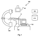
図1は、画像処理システム100を備える撮像システムを示す。画像処理システム100は、開始点2と脈管系5内の対象目標地点4との間の(図3及び図5に示される)脈管経路3で使用するための(図4に示される)少なくとも1つのカテーテルタイプ21、31、41、51、61を決定するためのものである。
FIG. 1 shows an imaging system including an
例示的な実施形態において、撮像システム400は、任意選択的なテーブル10上で患者の画像を撮影するために配置されたx線機械300などの撮像デバイスを備える。汎用コンピュータなどの画像処理システム100が、撮像デバイス300に動作可能に接続され、撮像デバイス300からの画像を処理する。処理された画像は、撮像システム400のディスプレイユニット140に提示される。
In the exemplary embodiment,
撮像デバイス300は、磁気共鳴撮像(MRI)デバイス、コンピュータ断層撮影(CT)撮像デバイスを備える。撮像デバイス300は画像処理システム100と連携して、患者10の関心領域の脈管造影像を取得することができる。脈管造影像は、2次元及び/又は3次元である。特定の例は、2次元デジタルサブトラクション脈管造影(DSA:digital subtraction angiography)及び/又は3次元回転脈管造影RA像を含む。平均化などの任意の知られた技術により統合された2つ以上の脈管造影図を組み合わせることが可能である。
The
撮像システムは、利用可能なカテーテルに関する情報を記憶したデータベース210をさらに備える。特に、データベース210は、カテーテルタイプ識別番号を、カテーテルタイプに対する幾何学的情報、並びに場合によっては柔軟性(又は、その逆として剛性)及び/又は弾性などの材料の性質と関係付ける。データベース210内の幾何学的情報は、図4に示されて以下でさらに説明されるものなどの、利用可能なカテーテルの成形された端部23a、33a、43a、53a、63aの形状を分類する幾何学的情報などの様々なカテーテルの形状に関する情報を含む。形状の分類は、屈曲を幾何学的に特徴付ける情報を含む。例えば、幾何学的情報は、成形された端部23a、…における屈曲の角度、曲率半径(例えば内側及び外側の曲率半径)、カテーテル23の最大直径などを含む。(以下でさらに説明されるように)特定の経路3のための適切なカテーテルの決定が、特定の部位にいる執刀医にとって実際に利用可能なカテーテルを考慮し得るように、データベース210が特定の部位における利用可能なカテーテルの在庫150の電子バージョンと通信する。
The imaging system further includes a
画像処理システム100が、図2にさらに詳細に示される。画像処理システムは、少なくとも1つのプロセッサ110を備える。プロセッサ110は、メモリ120に動作可能に接続される。プロセッサ110及びメモリ120は、バス130を通して接続される。プロセッサ110は、1つ又は複数のマイクロプロセッサなどのプログラム命令を実行することが可能な任意のデバイスである。メモリは、任意の揮発性又は不揮発性メモリデバイス、例えば、取り外し可能なディスク、ハードドライブ、CD、ランダムアクセスメモリ(RAM:Random Access Memory)、読み取り専用メモリ(ROM:Read Only Memory)などである。さらに、プロセッサ110は、汎用コンピュータ内で具現化される。
The
表示生成器141は、さらに、バス130を通してプロセッサ110に動作可能に接続される。表示生成器141は、ディスプレイユニット140のために画像の表示を生成するように構成され、ディスプレイユニット140は、医療画像を提示することが可能なグラフィカルユーザーインターフェース(GUI:graphical user interface)を提示することに適した任意のモニター、スクリーンなどである。
画像処理システム100は、撮像システム400の入力ユニット132からの入力を受信及び解釈するように構成された入力インターフェース131をさらに備える。入力ユニット132は、任意の知られた入力デバイス、例えば、タッチスクリーンデバイス、マウス、キーボードなどであり得る。
The
画像処理システム100は、任意選択的にバス130を通して、データベース210にアクセス可能である。このようなアクセスは、プロセッサ110が、カテーテル21のために決定された経路3に対する幾何学的情報を、データベース210に記憶された利用可能なカテーテルのための対応する幾何学的(及び他の)情報と比較することができるように必要とされる。
示される実施形態において、撮像デバイス300は、プロセッサ110に動作可能に接続される。撮像デバイス300は、撮像データを取得し、撮像データは、脈管系5の脈管造影図を生成するように処理するためのプロセッサ110に提供される。脈管造影図は、次に、ディスプレイ140において提示される。
In the illustrated embodiment, the
メモリ120には、撮像デバイス300からの画像を処理するためにプロセッサ110により実行可能なプログラム命令122がコード化されている。ディスプレイ140における提示のために画像を処理するためのプログラム命令122に加えて、特に図6のフロー図を参照しながら本明細書でさらに説明されるように、少なくとも1つのカテーテルが脈管系5を辿ることを必要とする処置で使用するための少なくとも1つのカテーテルを決定する方法を実施する命令のプログラム124がさらに提供される。
The
画像処理システム100は、撮像デバイス300と同じ場所にあるか、又は遠隔に位置し、又は、画像処理システム100は、分散アーキテクチャを形成する。分散アーキテクチャの一例として、少なくとも1つのプロセッサ110が、撮像デバイス300と共に配置されて、ディスプレイ140における表示のために実質的にライブの脈管造影像を生成する。さらに、少なくとも1つのプロセッサ110は、患者10の既存の脈管造影像を利用する処置の事前計画のために別の場所に位置する。別の場所に位置する少なくとも1つのプロセッサ110は、少なくとも1つのカテーテルが脈管系5を辿ることを必要とする介入処置で使用するための少なくとも1つのカテーテルを決定するための命令のプログラム124を実行するように構成される。
The
図1を参照すると、撮像システム400は、図4に示されるようなある範囲の利用可能なカテーテル21、…を備えるカテーテル150の物理的な在庫をさらに備える。執刀医は、所与の脈管経路5に最も適しているとプロセッサ110により決定されたカテーテルに従った処置において、在庫150からカテーテル21を使用する。
Referring to FIG. 1, the
様々な実施形態において、プロセッサ110は、開始点2から対象目標地点4までの脈管系5の脈管造影図撮像データに基づいて、コンピュータプログラム124の指令下で、脈管経路5を決定するように構成される。1つ又は複数の脈管造影図を通した脈管系5は、通常、公開文献WO2006/090324、米国特許出願公開第2008/02755467号に記載されるものなどの知られた技術又は経路予測器を使用して評価される。プロセッサ110は、血管セグメント分けアルゴリズムを使用して開始点2から対象目標地点5までの脈管経路3を演算するように構成される。特に、血管セグメント分けは、脈管造影図撮像データに対して実施されて、1つ又は複数の知られた技術に従って脈管系5のモデルを抽出する。プロセッサ110は、開始点2から対象目標地点5までの経路3であって、この経路3に沿って少なくとも1つのカテーテル21が対象目標地点に達するために通る、経路3を決定するように構成される。経路2は、脈管系5のモデルを使用して、及び、知られた経路発見アルゴリズムに基づいて、自動化又は半自動化された手法で決定される。例えば、経路発見アルゴリズムは、経路2に沿って辿られる分岐の数を最小化すること、経路2の距離を最小化すること、若しくは、経路2に沿った血管の総断面積を最大化すること、又は、これらの技術の組み合わせに基づいて動作し得る。オペレーターは、入力ユニット132を使用して、経路発見アルゴリズムに従って示された提案された経路2を調節又は再規定する。経路発見アルゴリズムは、医療従事者が選択を行い得るように、ディスプレイユニット140を通して、医療従事者のために経路の画像内に通常描かれる複数の可能な経路を示す。しかし、他の経路が過度に蛇行している、及び/又は血栓症の危険性が過度に大きいか又は不適切であるという理由から、通常、容易に利用可能なアクセス点2から対象目標地点4までは1つの現実的な脈管経路しか存在しない。
In various embodiments, the
図3を参照して以下で説明されるように、ディスプレイユニット140などのディスプレイユニットは、決定された経路2を表示するように構成される。決定された経路2は、処置計画の一部として、及び、続いて処置中にカテーテル21の動きを追跡するために表示される。
As described below with reference to FIG. 3, a display unit, such as
開始位置2及び/又は対象位置4は、入力ユニット132を通してオペレーターにより選択される。手動アプローチでは、オペレーターは、脈管系5におけるアクセス又は開始点2を決定する。このアクセス点は、皮膚上であるか、又は可能な場合は患者の体内にあるが、目的が対象目標地点4まで薬剤などを送達することなので、通常は動脈である。代替的に、より自動化されたアプローチでは、ソフトウェアアルゴリズムは、脈管系5の撮影された脈管造影図から、経路発見アルゴリズムを使用して、対象目標地点4までの異なる脈管経路を伴う多くのアクセス点が存在することを特定する。対象位置4は、また、入力ユニット132を通したオペレーター入力によりさらに誘導される疾患発見プログラムを使用してプロセッサ110によりアルゴリズムにより決定される。このような疾患発見プログラムは、可能性のある腫瘍、血管狭窄、及び他の疾患対象部位の位置を特定することが可能であり得る。
The
従って、プロセッサ110は、撮像デバイス300から取得された完全脈管造影図のシーケンスに基づいて、1つ又は複数の開始点2から最終目標地点4までの脈管経路3を決定するために、(例えば上述のセグメント分けアルゴリズム及び経路発見アルゴリズムを含む)脈管の脈管造影図アルゴリズムツールを使用するように構成される。
Accordingly, the
図3は、脈管系5の典型的な脈管造影図1の画像である。図3に示す実施形態において、脈管造影図は、腎臓脈管造影図である。しかし、解剖学的構造の他の部分の脈管造影図が、可能な脈管系、例えば、冠動脈造影図、下肢脈管造影図、頸動脈造影図など、及びそれらの組み合わせを提供するものとして含まれる。
FIG. 3 is an image of a typical angiogram 1 of the
図3に示されるように、画像は、(上述のように決定又は選択された)アクセス点又は開始位置2、(上述のように決定又は選択された)目標地点位置4、及び、対象目標地点又は位置4までの(上述のように決定された)脈管経路3を示す線を含む。脈管経路3は、手術処置前に、及び手術処置中のカテーテル21のライブ追跡中に、カテーテル21のための移動経路を示す。決定された脈管経路3及び脈管造影像は、例えばディスプレイユニット140を通した表示のために同じ画像内に表示される。
As shown in FIG. 3, the image consists of an access point or start position 2 (determined or selected as described above), a target point position 4 (determined or selected as described above), and a target target point. Or a line indicating vascular path 3 (determined as described above) up to position 4. Vascular path 3 shows the travel path for
理解され得るように、脈管系5は、概して、複雑な樹枝状構造物である。脈管経路3は概して、主血管又は幹血管からより小さくより狭い分岐血管内に進み、最終的に対象目標地点又は位置4に達する。理解されるように、対象位置4は、その周りの組織に血液を送り込む比較的小さな毛細血管サイズの血管を含む。決定された脈管経路3は、その脈管系5内の少なくとも1つの分岐を辿る。図3に、接合部6、7、8において脈管経路3内の3つの分岐点が示される。これら分岐点の間には、図5に示されるように血管セグメント3a、3b、及び3cが存在する。
As can be appreciated, the
様々な実施形態において、プロセッサ110は、少なくとも、脈管系が分岐をもつ接合部6、7、8であって、決定された脈管経路3が脈管系5の分岐のうちの1つを通る接合部6、7、8において、脈管経路3内の少なくとも1つの幾何学値を決定するように構成される。そうするために、脈管造影図撮像データの血管セグメント分けに基づいて構築された脈管系5の上述のモデルは、脈管経路3に関する幾何学値を抽出するために使用される。例えば、決定された脈管経路3に沿った各接合部6、7、8において、決定された経路3の曲率半径及び/又は角度が、アルゴリズムにより決定される。さらに、血管径又は断面積データは、接合部6、7、8間の血管の各セグメント3a、3b、3cに対して抽出される。このような幾何学的データ抽出は、プロセッサ110により実施される1つ又は複数の知られたコンピュータにより実施される定量脈管分析(QVA:quantitative vascular analysis)技術を使用して実施され得る。
In various embodiments, the
様々な実施形態において、プロセッサ110は、データベース210に記憶されたある範囲の利用可能なカテーテルタイプから、少なくとも1つの幾何学値に適した少なくとも1つのカテーテルタイプを決定するように構成される。プロセッサ110は、脈管造影図撮像データから抽出された幾何学値を、データベース210に記憶された利用可能なカテーテルタイプ及び/又は少なくとも1つの材料の性質(弾性及び/又は剛性などの)の対応する幾何学値と比較するように構成される。カテーテルタイプが決定された経路3又は決定された経路3の一部(特に接合部6、7、8のうちの少なくとも1つ)に適しているという決定は、幾何学値の(所定の許容可能な同値性内の)同値性に基づいてなされる。追加的に、又は代替的に、プロセッサ110は、少なくとも1つの接合部6、7、8における脈管経路の少なくとも1つの幾何学値に基づいて、カテーテルに対する適切な少なくとも1つの材料の性質を調べるか、又は決定するように構成される。プロセッサ110は、適切な少なくとも1つの材料の性質を、データベース210に記憶された対応する少なくとも1つの材料の性質と比較して、少なくとも1つの適切なカテーテルタイプを決定するように構成される。
In various embodiments, the
一実施形態において、プロセッサ110は、経路3を、開始位置2、目標地点位置4、及び接合部6、7、8の間においてセグメント3a、3b、3cなどの複数の部分に分割する。プロセッサ110は、脈管造影図撮像データから決定された幾何学値と、データベース210から取得された対応する幾何学値との比較に基づいて、及び/又は、上述のような材料の性質の比較から、各接合部6、7、8及び各セグメント3a、3b、3cに対して少なくとも1つのカテーテルタイプを決定するように構成される。従って、プロセッサ110は、決定された経路3とその経路3を辿るための1つ又は複数のカテーテルタイプとの間における(所定の許容可能な公差内での)形状の同値性を演算するように構成される。
In one embodiment, the
従って、上述のように脈管経路3が決定されたとき、特に脈管系5の分岐ノード及び接合部における各分岐6、7、8の曲率半径及び角度の考慮に基づいて、形状にマッチングする1つ又は複数のカテーテルタイプの決定がプロセッサ110によりなされる。各分岐6、7、8は、脈管系5の樹枝状分岐が存在する結果、アクセス点2と最終目標地点4との間における脈管経路3を提供する1つの分岐又は別の分岐への曲がり角が存在する脈管系内の点である。
Therefore, when the vascular path 3 is determined as described above, it matches the shape based on consideration of the radius of curvature and angle of each
分岐という用語は、脈管系5が分かれる各ノードに関係して使用されるが、主分岐から2つを上回る子分岐が存在することが理解される。それは、その接合部における多くの候補となる分かれのうちの1つであるとみなされる、分岐ノード又は接合部において分かれた実際の検出された脈管経路3の分岐である。通常、1つの脈管経路3のみが、考慮された経路3内の各分岐における曲率半径及び角度の観点からセグメントごとに考慮される。
The term branch is used in connection with each node from which the
セグメントごとの決定された脈管経路3又は分岐点6、7、8間のセクションの幾何学値又は寸法(曲率半径/角度)の観点での考慮は、次の分岐点6、7、8の必要性の観点から、各セグメントに対する最適なカテーテル形状タイプの決定を可能にする。各セグメントは、脈管系5において分岐した接合部6、7、8又はノード間の脈管の一部である。脈管系5などの分岐ネットワークにおいて、後続の分岐はより狭くなる傾向があるので、初期分岐は次の分岐より幅が広く、以下、対象目標地点4まで同様に続く。
Consideration in terms of geometric values or dimensions (radius of curvature / angle) of the section between the determined vascular path 3 or
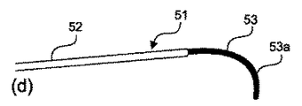
図4は、カテーテルタイプ21、31、41、51、61の例を示し、この例から、所与の処置及び所与の決定された脈管経路3のためにどのカテーテルが使用されるかについて選択がなされ得る。カテーテルは概して、成形された端部をもつ管を備える。図4は、異なるカテーテルタイプの例示的な副図4(a)〜副図4(e)を提供する。理解され得るように、カテーテルは、管の孔幅寸法により区別されることに加えて、カテーテルの入口端部又は入口先端の形状により分類される。これらの形状は、その特徴的な成形された端部23、33、43、53、63を生成する形状記憶を備える。徐々に小さくなる管孔寸法の同心での組み合わせでいくつかのカテーテルが示される場合、必要とされるまで他のカテーテルが最も広い管孔内に引き込まれた状態で、最も広いものがその成形された端部に最初に現れる。このようなカテーテルの組み合わせは利点をもち、特に、分岐ノード6、7、8及び脈管経路3のセグメントの間でカテーテルを引き抜く必要を無くす。成形された端部をもつ必要なカテーテルタイプの同心でのカテーテルの組み合わせが組み立てられる。1つのカテーテルが経路に沿って挿入されて、次に、分岐した接合部において分岐を越えた後、別のカテーテルがより幅の広い第1のカテーテルに沿って、及びより幅の広い第1のカテーテル内を通されて、脈管経路の次のセグメント内へと奥に延び、別の接合部又はノードにおける次の分岐に向けて、及び次の分岐まで奥に延び、以降も同様に続くように、この組み立ては、挿入前及び/又はその場でなされ得る。このアプローチは、カテーテルの組み合わせが最終目標地点4に達するまで続く。最初に形成された同心でのカテーテルの組み合わせは、次の分岐6、7、8のためのカテーテル形状が露出されると共に他が引き抜かれながら、アクセス又は開始点2から経路3に沿って送り込まれるか、又は押される。次に、その分岐に最適なカテーテル形状タイプが、その次の分岐6、7、8に係合してそこを通る。このような係合は、カテーテルの成形された端部を、開いた分岐をまたぐ留め具として機能したまま残すか、又は分岐を越えて通るが、いずれにしても、次に、同心での組み合わせの次のカテーテルが、経路3に沿って以前のカテーテルを越えて次の分岐6、7、8まで前方に押されるか、又は送り込まれる。
FIG. 4 shows an example of
図2(a)は、送り込まれる管22と、管22に対して約30度の傾斜した先端23aを備える成形された端部23とを含むカテーテル21を示す。図2(b)は、送り込まれる管32と、管32に対して約60度の傾斜した先端33aを備える成形された端部33とを含むカテーテル31を示す。図2(c)は、送り込まれる管42と、管42に対して約90度の傾斜した先端43aを備える成形された端部43を含むカテーテル41を示す。図2(d)は、送り込まれる管52と、四分円又は弧を張る湾曲した先端53aを備える成形された端部53を含むカテーテル51を示す。図2(e)は、送り込まれる管62と、S字形先端63aを備える成形された端部63とを含むカテーテル61を示す。各端部23、33、43、53、63、及び特に先端23a、33a、43a、53a、63aは、曲率半径及び/若しくは角度、並びに/又は、全体形状の観点から異なる分岐構成に最適である。従って、脈管経路3が分岐6、7、8の観点から決定された後、接合部又はノード6、7、8における各分岐に対して、最良の端部23、33、43、53、63がプロセッサ110によりさらに決定される。
FIG. 2 (a) shows a
分岐ノード6、7、8間における脈管経路3のセグメント3a、3b、3cは、最終対象部位4に向かって順々に異なる寸法をもつことが理解される。これらのセグメント3a、3b、3cは、管22、32、42、52、62と調和するのに対して、端部23、33、43、53、63は、分岐6、7、8を介して次のセグメントに入ることを円滑化する。
It will be understood that the
様々な実施形態において、プロセッサ110は、決定された少なくとも1つのカテーテルタイプの指示を出力するように構成される。通常、出力は、ディスプレイユニット104などのディスプレイユニットに表示される。決定された少なくとも1つのカテーテルタイプの指示は、複数のカテーテルタイプが処置のために決定されたとき、使用のシーケンスの指示を含む。例示的な実施形態において、出力は、脈管造影図撮像データに基づいて決定された経路3に沿った脈管系5の少なくとも1つの画像を、決定された経路3の各部分におけるカテーテルタイプを示す重ねられたグラフィックに組み合わせる。脈管経路3に対して複数のカテーテルが決定された場合は、色コード分けされたグラフィックの重ね合わせが使用される。
In various embodiments, the
出力について、図5に示す例示的な実施形態を参照しながらさらに説明する。 The output will be further described with reference to the exemplary embodiment shown in FIG.
図5は、セグメント3a、3b、3cと共に示される開始又はアクセス点2と対象目標地点4との間の脈管経路3を含む、図3に示されるものと同様の脈管造影図のさらなる例を提供する。各セグメント3a、3b、3cは、開始/アクセス点2、分岐接合部又はノード6、7、8、及び対象目標地点4のそれぞれの間に延びる。各セグメント3a、3b、3cが、形状の観点で指定されたカテーテルを含む。オペレーターは、画像内でマーキングされた経路における色変化などの脈管系の脈管造影像内の指示により、経路3の各セグメント3a、3b、3cに対して提案されたカテーテルタイプを使用するように促される。
FIG. 5 is a further example of an angiogram similar to that shown in FIG. 3, including the vascular path 3 between the start or
図5に示される経路3において、及び、画像内でオペレーターに示される際には、様々なセグメント3a、3b、3cが、色コードとして示される。各色コードは、画像内において経路のそれぞれのセグメント3a、3b、3cに重なり、その色コードは特定のカテーテルタイプに対して与えられた色コードと相関する。各色コードはカテーテルのタイプに対応するので、医師などのオペレーターが脈管経路3の各セグメント3a、3b、3cに対してどのカテーテルを使用するか知ることを可能にする。典型的には、各色コードは、経路3のセグメント3a、3b、3cに一致した脈管に適合するカテーテル寸法をさらに提案する。典型的には、セグメント3a内の脈管はセグメント3bより幅が広く、セグメント3bはセグメント3cより幅が広く、カテーテルタイプの並びのシーケンスが必要に応じて示される。
In the path 3 shown in FIG. 5 and when shown to the operator in the image, the
色コードに加えて、他の視覚的に識別可能な差別化要素が、1つ又は複数の特定のカテーテルタイプを表すために脈管造影図撮像データの表示において使用される。 In addition to the color code, other visually identifiable differentiating elements are used in the display of angiographic imaging data to represent one or more specific catheter types.
さらに、カテーテルタイプのモデルが重ね合わせの一部として使用され得る。カテーテルタイプのモデルは、縮尺通りに、脈管経路のセグメントに沿った位置に重ねられ得る。モデルは、予め規定されてデータベース210に記憶され得る。例えば、1つを上回るカテーテルタイプが使用される場合、色コード分けされた手法で、脈管造影図撮像データの表示に含まれるワイヤフレームモデルが使用され得る。
In addition, a catheter type model can be used as part of the overlay. Catheter-type models can be overlaid to scale along a segment of the vascular pathway. The model may be pre-defined and stored in the
様々な実施形態において、プロセッサ110は、脈管経路3に沿った決定された少なくとも1つのカテーテルタイプの使用位置を決定するように構成される。例えば、各カテーテルタイプの端部位置が決定され、接合部6、7、8を辿るために適切に成形された端部23をもつより大きなカテーテルタイプの端部からより小さなカテーテルタイプが入れ子状に伸縮し得るように、各カテーテルタイプの端部位置は通常、接合部6、7、8に隣接する。出力は、カテーテルが終端する脈管経路3に沿って決定された位置におけるカテーテルの遠位端の位置を示す、脈管経路に沿って重ねられたカテーテルの表現(例えば上述のようにカテーテルのモデル)を含む。
In various embodiments, the
様々な実施形態において、処置に使用される少なくとも1つのカテーテルタイプの決定に応答して、在庫150から医療専門家に指令が出される。執刀医は続いて、処置にそれらのカテーテルを使用し得る。在庫150からの少なくとも1つのカテーテルに関する指令は、少なくとも1つのカテーテルタイプの決定に応答して、自動的に少なくとも1つのプロセッサ110により照合及び送信される。
In various embodiments, a medical professional is instructed from
様々な実施形態において、プロセッサ110は、処置中に(表示生成器141を使用して)ディスプレイユニット140に、決定された脈管経路3と、脈管造影図撮像データと、任意選択的にさらに少なくとも1つのカテーテルタイプの重ね合わせとの組み合わせを示すように構成される。さらに、プロセッサ110は、撮像デバイス300と連携して、脈管経路3に沿ったカテーテルの動きをライブで追跡するように構成される。このように、1つ又は複数のカテーテルが決定された脈管経路3を辿るために通る必要のある脈管系5に沿った転換ごとにガイダンスが提供される。さらに、カテーテルが終端する位置、及び任意選択的にそこから延びた入れ子のカテーテルについてガイダンスが提供される。
In various embodiments, the
ここで図6を参照すると、介入処置で使用するための少なくとも1つのカテーテルタイプを決定するための例示的な方法が開示される。本方法は、少なくとも1つのコンピュータプログラム124の命令により指示された少なくとも1つのプロセッサ110により行われるという点でコンピュータにより実施される。本方法は、開始点2と脈管系5内の対象目標地点4との間で脈管経路3を辿るときに使用する1つ又は複数の適切なカテーテルタイプを決定することができる。
With reference now to FIG. 6, an exemplary method for determining at least one catheter type for use in an interventional procedure is disclosed. The method is implemented by a computer in that it is performed by at least one
ステップ510において、脈管造影図撮像データは、プロセッサ110により、任意選択的にデータインターフェースユニット(図示されない)及びバス130により受信される。撮像データは、通常、CTデバイスなどのX線ベースの撮像デバイス300である撮像デバイス300を使用して、撮像手順により事前に取得される。
At
ステップ520において、脈管造影図撮像データが、脈管系5の関心領域のモデルを取得するために、プロセッサ110により処理される。モデルは、脈管造影図撮像データに対して血管セグメント分け画像処理技術を使用して取得される。
At
ステップ530において、プロセッサ110は、カテーテルベースの処置のための開始点2及び対象目標地点4を受信する。開始位置2及び対象位置4のいずれか又は両方が、ユーザー入力ユニット132を通してユーザーにより選択されるか、又は、プロセッサ110によりアルゴリズムにより決定される。
In
ステップ540において、プロセッサ110は、脈管系のモデルと、受信された開始位置2及び対象位置4とを使用して、介入処置中におけるカテーテルの通過のための推奨案として脈管経路3を決定する。プロセッサ110は、(例えばユーザーの嗜好又はユーザー入力ユニット132からの変更を考慮することにより)自動化又は半自動化された手法で脈管経路3を決定する。プロセッサ110は、経路発見アルゴリズムを使用して脈管経路を決定する。
In
ステップ550において、プロセッサ110は、脈管造影図撮像データに基づいて、脈管経路の幾何学値を決定する。幾何学値は、接合部6、7、8における曲率半径及び/又は屈曲の角度、及び/又は、接合部6、7、8間における各セグメント3a、3b、3cの最小孔寸法、及び/又は、各接合部6、7、8の最小孔寸法を含む。幾何学値は、通常、血管セグメント分けアルゴリズムによりセグメント分けされた撮像データに基づいて、定量脈管分析技術を使用して、及び、場合によってはステップ520に従って構築されたモデルを使用してプロセッサ110により決定される。
In
ステップ560において、プロセッサ110は、脈管経路の幾何学値に基づいて、データベース210に記憶されたある範囲の利用可能なカテーテルタイプから、決定された脈管経路3に適した少なくとも1つのカテーテルタイプを決定する。特に、プロセッサ110は、脈管経路に対する決定された幾何学値を、データベース210に記憶されたカテーテルタイプに対する対応する幾何学値と比較する。追加的に、又は代替的に、プロセッサ110は、決定された幾何学値をもつ脈管経路を辿るために必要とされる1つ又は複数の適切な材料の性質を計算又は参照する。プロセッサ110は、適切な材料の性質(剛性及び/又は弾性などの)を、データベース210内の対応する材料の性質と比較して、少なくとも1つの適切なカテーテルタイプを決定する。このように、幾何学値及び/又は材料の性質などの記憶及び決定された性質の(所定の公差内での)同値性に基づいて、決定された脈管経路3に適した少なくとも1つのカテーテルが決定される。
At
ステップ570において、プロセッサ110は、決定された少なくとも1つのカテーテルタイプの指示を出力する。例えば、プロセッサ110は、表示生成器141と共同して動作して、ディスプレイユニット140における表示のために画像を生成する。画像は、脈管造影図撮像データと、脈管経路3の表現と、さらに、幾何学値に基づいてステップ560において決定された、脈管経路3に沿った各カテーテルの位置の表現とを組み合わせる。脈管経路3の表現及び各カテーテルの表現は、脈管造影図撮像データの表示内で脈管経路3に沿ってその場で縮尺通りに決定されたカテーテルの各々のモデルである。表現は、重ね合わせの形態である。さらに、脈管経路3を辿るために1つを上回るカテーテルが決定された場合、各カテーテルの視覚的に差別化した表現が、例えば色コード分けの手法により重ね合わせにおいて示される。
In
図6に示され、ここまでに説明される方法は、事前処置計画工程の一部である。決定されたカテーテルタイプが、続いて在庫150から取得され得る。出力は、メモリ120に記憶され得る。出力は、続いて、医療専門家が脈管経路、及び脈管経路3に沿った各カテーテルの終了位置を把握し得るように、処置のライブ追跡中に使用され得る。
The method shown in FIG. 6 and described so far is part of the pre-treatment planning process. The determined catheter type can then be obtained from
本発明の別の例示的な実施形態では、適切なシステムにおいて、先行する実施形態のうちの1つに従った方法の方法ステップを実行するように適応されることを特徴とする、コンピュータプログラム又はコンピュータプログラム要素が提供される。 In another exemplary embodiment of the present invention, a computer program or a computer program characterized in that it is adapted to perform the method steps of the method according to one of the preceding embodiments in a suitable system A computer program element is provided.
コンピュータプログラム要素は、従って、本発明の一実施形態の一部であるコンピュータユニットに記憶される。この演算ユニットは、上述の方法のステップを実施するように、又は上述の方法のステップの実施を誘導するように適応される。さらに、演算ユニットは、上述の装置のコンポーネントを動作させるように適応される。演算ユニットは、自動的に動作するように、及び/又はユーザーの命令を実行するように適応され得る。コンピュータプログラムは、データプロセッサの作業メモリにロードされる。データプロセッサは、従って、本発明の方法を実施するように装備される。 The computer program elements are therefore stored in a computer unit that is part of one embodiment of the present invention. This computing unit is adapted to carry out the method steps described above or to guide the implementation of the method steps described above. In addition, the arithmetic unit is adapted to operate the components of the device described above. The computing unit may be adapted to operate automatically and / or to execute user instructions. The computer program is loaded into the working memory of the data processor. The data processor is therefore equipped to carry out the method of the invention.
本発明のこの例示的な実施形態は、全く最初から本発明を使用するコンピュータプログラムと、更新により既存のプログラムを、本発明を使用するプログラムに変換するコンピュータプログラムとの両方をカバーする。 This exemplary embodiment of the invention covers both computer programs that use the invention from scratch and computer programs that convert existing programs into programs that use the invention by updating.
さらに、コンピュータプログラム要素は、上述のような方法の例示的な実施形態の手順を満たすすべての必要なステップを提供することが可能である。 In addition, the computer program element can provide all necessary steps that satisfy the procedures of the exemplary embodiments of the method as described above.
本発明のさらなる例示的な実施形態によると、CD−ROMなどのコンピュータ可読媒体が提示され、コンピュータ可読媒体は、コンピュータ可読媒体に記憶されたコンピュータプログラム要素を含み、このコンピュータプログラム要素はこれまでのセクションにより説明される。 According to a further exemplary embodiment of the present invention, a computer readable medium such as a CD-ROM is presented, the computer readable medium including computer program elements stored on the computer readable medium, Explained by section.
コンピュータプログラムは、他のハードウェアと一体的に、又は他のハードウェアの一部として供給される光記憶媒体又はソリッドステート媒体などの適切な媒体に記憶及び/又は配布されるが、インターネット又は他の有線又は無線電気通信システムを介することなどにより、他の形態でも配布される。 The computer program may be stored and / or distributed on any suitable medium, such as an optical storage medium or solid-state medium supplied with or as part of other hardware, such as the Internet or other Also distributed in other forms, such as via a wired or wireless telecommunications system.
しかし、コンピュータプログラムは、また、ワールドワイドウェブといったネットワークを通じて提示され、このようなネットワークからデータプロセッサの作業メモリ内にダウンロードされ得る。本発明のさらなる例示的な実施形態によると、ダウンロードのためにコンピュータプログラム要素を利用可能にする媒体が提供され、このコンピュータプログラム要素が本発明の上述の実施形態のうちの1つに従った方法を実行するように構成される。 However, the computer program can also be presented through a network such as the World Wide Web and downloaded from such a network into the working memory of the data processor. According to a further exemplary embodiment of the present invention, there is provided a medium that makes a computer program element available for download, the computer program element being a method according to one of the above-described embodiments of the present invention. Configured to perform.
本発明の実施形態が異なる主題との関連において説明されることに注意が必要である。特に、いくつかの実施形態が方法形態の請求項に関連して説明されるのに対して、他の実施形態はデバイス形態の請求項を参照しながら説明される。しかし、当業者は、上述の内容と以下の説明とを参照して、別段の記載がない限り、一つの形態の主題に属する特徴の任意の組み合わせに加えて、異なる主題に関する特徴の間の任意の組み合わせも本出願において開示されるとみなされることを理解する。しかし、すべての特徴が組み合わされて、特徴の単なる足し合わせを上回る相乗効果を提供し得る。 Note that embodiments of the invention are described in the context of different subjects. In particular, some embodiments will be described with reference to method form claims whereas other embodiments will be described with reference to device form claims. However, one of ordinary skill in the art, with reference to what has been described above and the following description, unless noted otherwise, in addition to any combination of features belonging to a form of subject matter, It will be understood that combinations of are considered to be disclosed in this application. However, all the features can be combined to provide a synergistic effect over the mere summation of the features.
少なくとも1つの例示的な実施形態がここまでの詳細な説明に示されるが、膨大な数の変形例が存在することが理解される。1つ又は複数の例示的な実施形態が単なる例示であり、いかなる手法によっても本開示の範囲、適用可能性、及び構成を限定するように意図されないことも理解される。むしろ、前述の詳細な説明は、1つ又は複数の例示的な実施形態を実現するための利便性の高い指針を当業者に提供する。付属の特許請求の範囲に記載された本開示の範囲、及び特許請求の範囲と法的に均等なものから逸脱することなく、要素の機能及び構成に様々な変更がなされ得ることが理解される。 While at least one exemplary embodiment has been presented in the foregoing detailed description, it will be appreciated that a vast number of variations exist. It is also understood that the exemplary embodiment or exemplary embodiments are only examples, and are not intended to limit the scope, applicability, and configuration of the disclosure in any manner. Rather, the foregoing detailed description provides those skilled in the art with convenient guidance for implementing one or more exemplary embodiments. It will be understood that various changes may be made in the function and arrangement of elements without departing from the scope of the disclosure as set forth in the appended claims and from the legal equivalents of the claims. .
例えば、脈管系内の脈管経路の脈管造影像内に表示された、又は別様に表示された色コードと一致する色コード又は他のコードをもつカテーテルタイプのセットが、在庫から供給され得る。各カテーテルタイプに対する各送り込み孔寸法範囲内のカテーテルは、これらが脈管系内への挿入中又は挿入前に同心でのカテーテルの組み合わせとして組み合わされ得ることを意味する。 For example, a set of catheter types with a color code or other code displayed in an angiographic image of a vascular pathway in the vasculature or with a color code that is otherwise displayed is supplied from inventory Can be done. Catheters within each delivery hole size range for each catheter type means that they can be combined as a concentric catheter combination during or prior to insertion into the vasculature.
特許請求の範囲において、「備える」という用語は、他の要素もステップも排除せず、「1つ(a)」又は「1つ(an)」という単数表現の不定冠詞は、複数を排除しない。単一のプロセッサ又は他のユニットが、特許請求の範囲において列挙されたいくつかの項目の機能を果たす。単に特定の手段が相互に異なる従属請求項に列挙されるということが、利点を得るためにこれらの手段の組み合わせが使用されることができないということを示すわけではない。特許請求の範囲における参照符号は、いずれも特許請求の範囲を限定するように解釈されてはならない。 In the claims, the term “comprising” does not exclude other elements or steps, and the indefinite article “a” or “an” does not exclude a plurality. . A single processor or other unit performs the functions of several items recited in the claims. The mere fact that certain measures are recited in mutually different dependent claims does not indicate that a combination of these measures cannot be used to obtain an advantage. Any reference signs in the claims should not be construed as limiting the claim.
Claims (15)
前記開始点から前記対象目標地点までの前記脈管系の脈管造影図撮像データに基づいて、前記脈管経路を決定することと、
前記脈管造影図撮像データを使用して、少なくとも、前記脈管系が分岐をもつ接合部であって、前記脈管経路が前記脈管系の前記分岐のうちの1つを通る接合部における、前記脈管経路内の少なくとも1つの幾何学値を決定することと、
データベースに記憶されたある範囲の利用可能な長尺脈管内デバイスタイプから、前記少なくとも1つの幾何学値に適した少なくとも1つの長尺脈管内デバイスタイプを決定することと、
決定された前記少なくとも1つの長尺脈管内デバイスタイプの指示を出力することと、
を行う少なくとも1つのプロセッサを備え、
前記少なくとも1つのプロセッサが、前記脈管経路に沿って使用される長尺脈管内デバイスタイプのシーケンスを決定し、決定された前記長尺脈管内デバイスタイプのシーケンスの前記指示を出力する、
画像処理システム。 An image processing system for determining at least one elongated intravascular device type for use in following a vascular path between a starting point and a target target point in the vascular system, the image processing system comprising: ,
Determining the vascular path based on angiographic imaging data of the vascular system from the start point to the target target point;
Using the angiogram imaging data, at least at the junction where the vasculature has a branch and the vascular pathway passes through one of the branches of the vasculature Determining at least one geometric value in the vascular pathway;
Determining, from a range of available long intravascular device types stored in a database, at least one long intravascular device type suitable for the at least one geometric value;
Outputting an indication of the determined at least one elongated intravascular device type;
Comprising at least one processor for performing
The at least one processor determines a sequence of long intravascular device types used along the vascular path and outputs the indication of the determined sequence of long intravascular device types;
Image processing system.
請求項1に記載の画像処理システム。 The at least one processor determines a use position of the determined long intravascular device type along the vascular path;
The image processing system according to claim 1.
請求項2に記載の画像処理システム。 The at least one processor overlays a graphical indication of the determined long intravascular device type at the use location in at least one image for display corresponding to the angiographic imaging data; Outputting the indication of the determined long intravascular device type;
The image processing system according to claim 2.
請求項3に記載の画像処理システム。 A model of the long intravascular device type determined by the at least one processor as the iconic indication shown on-site to scale in at least one image corresponding to the angiographic imaging data; Use the
The image processing system according to claim 3.
請求項1から請求項4のいずれか一項に記載の画像処理システム。 A different iconic indication of each of the determined long intravascular device types is superimposed in the at least one image;
The image processing system according to any one of claims 1 to 4.
請求項1から請求項5のいずれか一項に記載の画像処理システム。 The at least one processor outputs a series of catheter type instructions;
The image processing system according to any one of claims 1 to 5.
請求項1から請求項6のいずれか一項に記載の画像処理システム。 The at least one geometric value is a radius of curvature and / or an angle of the vascular pathway at the junction;
The image processing system according to any one of claims 1 to 6.
請求項1から請求項7のいずれか一項に記載の画像処理システム。 The at least one processor based on a comparison of the at least one geometric value and a corresponding geometric value of the available long intravascular device type stored in the database; Determining the at least one elongated intravascular device type for following the bifurcation of the vascular system;
The image processing system according to any one of claims 1 to 7.
請求項1から請求項8のいずれか一項に記載の画像処理システム。 The at least one processor determines geometric values in the vascular path at each junction along the vascular path and in at least one inter-junction segment;
The image processing system according to any one of claims 1 to 8.
請求項9に記載の画像処理システム。 The geometric value includes a diameter and / or cross-sectional area of the at least one inter-joint segment and the radius of curvature and / or angle of a path at the joint;
The image processing system according to claim 9.
請求項1から請求項10のいずれか一項に記載の画像処理システム。 The at least one processor generates an image of the vascular path including an inter-junction segment from which the vascular path branches, and the output is determined at least in the image of the segment. A visually distinguishable indication of the elongated intravascular device type;
The image processing system according to any one of claims 1 to 10.
前記脈管造影図撮像データを生成するための撮像デバイスと、
前記データベースと、
処置で使用するための決定された前記長尺脈管内デバイスタイプの長尺脈管内デバイスと、
のうちの少なくとも1つ、を備える、システム。 The image processing system according to any one of claims 1 to 11, and an imaging device for generating the angiogram imaging data,
The database;
A long intravascular device of the long intravascular device type determined for use in a procedure;
A system comprising at least one of the following.
前記開始点から前記対象目標地点までの前記脈管系の脈管造影図撮像データに基づいて、前記脈管経路を決定するステップと、
少なくとも、前記脈管系が分岐をもつ接合部であって、前記脈管経路が前記脈管系の前記分岐のうちの1つを通る接合部における、前記脈管経路内の少なくとも1つの幾何学値を、前記脈管造影図撮像データに基づいて決定するステップと、
データベースに記憶されたある範囲の利用可能な長尺脈管内デバイスタイプから、前記少なくとも1つの幾何学値に適した少なくとも1つの長尺脈管内デバイスタイプを決定するステップと、
決定された前記少なくとも1つの長尺脈管内デバイスタイプの指示を出力するステップと、
を有し、前記方法が、
前記脈管経路に沿って使用される長尺脈管内デバイスタイプのシーケンスを決定し、決定された前記長尺脈管内デバイスタイプの前記シーケンスの指示を出力するステップを有する、コンピュータにより実施される方法。 A computer-implemented method for determining at least one elongated intravascular device type for use in following a vascular path between a starting point and a target target point in the vascular system, the method comprising: But,
Determining the vascular path based on vascular angiogram imaging data of the vascular system from the start point to the target target point;
At least one geometry in the vascular pathway, at least at a junction where the vasculature has a bifurcation, and the vascular pathway passes through one of the bifurcations of the vascular system. Determining a value based on the angiogram imaging data;
Determining, from a range of available long intravascular device types stored in a database, at least one long intravascular device type suitable for the at least one geometric value;
Outputting an indication of the determined at least one elongated intravascular device type;
And the method comprises:
Determining a sequence of long intravascular device types to be used along the vascular path and outputting an indication of the determined sequence of the long intravascular device types. .
Applications Claiming Priority (5)
| Application Number | Priority Date | Filing Date | Title |
|---|---|---|---|
| US201662356580P | 2016-06-30 | 2016-06-30 | |
| US62/356,580 | 2016-06-30 | ||
| EP16181370 | 2016-07-27 | ||
| EP16181370.4 | 2016-07-27 | ||
| PCT/EP2017/066179 WO2018002250A1 (en) | 2016-06-30 | 2017-06-29 | Catheter type selection |
Publications (2)
| Publication Number | Publication Date |
|---|---|
| JP2019524200A true JP2019524200A (en) | 2019-09-05 |
| JP2019524200A5 JP2019524200A5 (en) | 2020-08-06 |
Family
ID=59350881
Family Applications (1)
| Application Number | Title | Priority Date | Filing Date |
|---|---|---|---|
| JP2018568242A Ceased JP2019524200A (en) | 2016-06-30 | 2017-06-29 | Selection of catheter type |
Country Status (4)
| Country | Link |
|---|---|
| US (1) | US11154259B2 (en) |
| EP (1) | EP3478156A1 (en) |
| JP (1) | JP2019524200A (en) |
| CN (1) | CN109414187A (en) |
Families Citing this family (3)
| Publication number | Priority date | Publication date | Assignee | Title |
|---|---|---|---|---|
| CN110051385B (en) * | 2019-05-29 | 2023-01-24 | 深圳华声医疗技术股份有限公司 | Full-automatic measurement method, device, storage medium and system based on blood vessel identification |
| US20220181024A1 (en) * | 2020-12-04 | 2022-06-09 | Biosense Webster (Israel) Ltd. | Catheter structure examination and optimization using medical procedure information |
| CN114366296B (en) * | 2021-12-31 | 2023-05-30 | 杭州脉流科技有限公司 | Improved microcatheter path generation methods, shaping methods, apparatus and storage medium |
Citations (2)
| Publication number | Priority date | Publication date | Assignee | Title |
|---|---|---|---|---|
| JP2006110351A (en) * | 2004-10-13 | 2006-04-27 | General Electric Co <Ge> | Method and apparatus for aligning 3d model and pursuit system in anatomical sector of heart by using projection image of intervening fluoroscopy system |
| US20110295199A1 (en) * | 2008-12-29 | 2011-12-01 | Koninklijke Philips Electronics N.V. | Planning and assembly of compensating concentric cannulas |
Family Cites Families (10)
| Publication number | Priority date | Publication date | Assignee | Title |
|---|---|---|---|---|
| US9974459B2 (en) | 2003-02-21 | 2018-05-22 | 3Dt Holdings, Llc | Localization of body lumen junctions |
| DE10358735B4 (en) * | 2003-12-15 | 2011-04-21 | Siemens Ag | Catheter device comprising a catheter, in particular an intravascular catheter |
| CN101128829B (en) | 2005-02-23 | 2010-05-19 | 皇家飞利浦电子股份有限公司 | Method and device for the prediction of the course of a catheter, method for manufacturing catheter |
| DE102006034388A1 (en) * | 2006-07-25 | 2008-01-31 | Siemens Ag | Hollow organ view producing method, involves recording three-dimensional volume data record of hollow organ and catheter, where position of catheter inserted into organ, is determined and intraluminal view of organ is produced |
| US20080275467A1 (en) | 2007-05-02 | 2008-11-06 | Siemens Corporate Research, Inc. | Intraoperative guidance for endovascular interventions via three-dimensional path planning, x-ray fluoroscopy, and image overlay |
| US20120014577A1 (en) | 2010-07-13 | 2012-01-19 | Sigrid Ferschel | Method and System for Indicating a Feeding Vessel of a Malformation |
| US9189866B2 (en) | 2013-03-11 | 2015-11-17 | Kabushiki Kaisha Toshiba | Vascular tree from anatomical landmarks and a clinical ontology |
| WO2014201119A2 (en) | 2013-06-11 | 2014-12-18 | Adventist Health System/Sunbelt, Inc. | Intra-operative fiducial system and method for neuronavigation |
| CN104095654B (en) | 2014-08-04 | 2016-05-25 | 深圳开立生物医疗科技股份有限公司 | A kind of conduit size choosing method, device and system |
| US10398509B2 (en) * | 2015-09-18 | 2019-09-03 | General Electric Company | System and method for optimal catheter selection for individual patient anatomy |
-
2017
- 2017-06-29 EP EP17739905.2A patent/EP3478156A1/en not_active Withdrawn
- 2017-06-29 US US16/307,985 patent/US11154259B2/en active Active
- 2017-06-29 CN CN201780041005.0A patent/CN109414187A/en active Pending
- 2017-06-29 JP JP2018568242A patent/JP2019524200A/en not_active Ceased
Patent Citations (2)
| Publication number | Priority date | Publication date | Assignee | Title |
|---|---|---|---|---|
| JP2006110351A (en) * | 2004-10-13 | 2006-04-27 | General Electric Co <Ge> | Method and apparatus for aligning 3d model and pursuit system in anatomical sector of heart by using projection image of intervening fluoroscopy system |
| US20110295199A1 (en) * | 2008-12-29 | 2011-12-01 | Koninklijke Philips Electronics N.V. | Planning and assembly of compensating concentric cannulas |
Also Published As
| Publication number | Publication date |
|---|---|
| CN109414187A (en) | 2019-03-01 |
| US11154259B2 (en) | 2021-10-26 |
| EP3478156A1 (en) | 2019-05-08 |
| US20190298278A1 (en) | 2019-10-03 |
Similar Documents
| Publication | Publication Date | Title |
|---|---|---|
| US11793389B2 (en) | Intelligent display | |
| JP7093801B2 (en) | A system that facilitates position adjustment and guidance during surgery | |
| US9098899B2 (en) | Determining the specific orientation of an object | |
| CN106999076B (en) | Automatic identification and classification of intravascular lesions | |
| CN106456126B (en) | Device for determining a specific position of a catheter | |
| JP6002667B2 (en) | 3D origin heart roadmap generation | |
| US8494246B2 (en) | Automatic pathway and waypoint generation and navigation method | |
| EP3313313B1 (en) | System for helping to guide an endovascular tool in vascular structures | |
| JP6574864B2 (en) | Method for displaying anatomical images of coronary arteries on a graphical user interface | |
| US11395702B2 (en) | Navigation system | |
| JP6434171B2 (en) | Image alignment | |
| JP2019524200A (en) | Selection of catheter type | |
| US20120296620A1 (en) | Device and method for planning an endovascular procedure with a medical instrument | |
| JP7299701B2 (en) | Navigation support system | |
| WO2018002250A1 (en) | Catheter type selection | |
| CN110494094B (en) | Characterizing behavior of anatomical structures | |
| JP2022507106A (en) | Systems and methods for mapping with anatomical measurement wires | |
| RU2574374C2 (en) | Determination of object's particular orientation | |
| CN117241735A (en) | Determining endpoint positions for stents | |
| WO2024058835A1 (en) | Assembly of medical images from different sources to create a 3-dimensional model |
Legal Events
| Date | Code | Title | Description |
|---|---|---|---|
| A521 | Request for written amendment filed |
Free format text: JAPANESE INTERMEDIATE CODE: A523 Effective date: 20200626 |
|
| A621 | Written request for application examination |
Free format text: JAPANESE INTERMEDIATE CODE: A621 Effective date: 20200626 |
|
| A977 | Report on retrieval |
Free format text: JAPANESE INTERMEDIATE CODE: A971007 Effective date: 20210528 |
|
| A131 | Notification of reasons for refusal |
Free format text: JAPANESE INTERMEDIATE CODE: A131 Effective date: 20210601 |
|
| A601 | Written request for extension of time |
Free format text: JAPANESE INTERMEDIATE CODE: A601 Effective date: 20210831 |
|
| A521 | Request for written amendment filed |
Free format text: JAPANESE INTERMEDIATE CODE: A523 Effective date: 20211130 |
|
| A01 | Written decision to grant a patent or to grant a registration (utility model) |
Free format text: JAPANESE INTERMEDIATE CODE: A01 Effective date: 20220427 |
|
| A045 | Written measure of dismissal of application [lapsed due to lack of payment] |
Free format text: JAPANESE INTERMEDIATE CODE: A045 Effective date: 20220830 |