JP2019523921A - Fisheye rendering with lens distortion correction for 360 degree video - Google Patents
Fisheye rendering with lens distortion correction for 360 degree video Download PDFInfo
- Publication number
- JP2019523921A JP2019523921A JP2018560066A JP2018560066A JP2019523921A JP 2019523921 A JP2019523921 A JP 2019523921A JP 2018560066 A JP2018560066 A JP 2018560066A JP 2018560066 A JP2018560066 A JP 2018560066A JP 2019523921 A JP2019523921 A JP 2019523921A
- Authority
- JP
- Japan
- Prior art keywords
- image
- video
- mapping
- dimensional
- video data
- Prior art date
- Legal status (The legal status is an assumption and is not a legal conclusion. Google has not performed a legal analysis and makes no representation as to the accuracy of the status listed.)
- Pending
Links
- 238000009877 rendering Methods 0.000 title abstract description 10
- 238000012937 correction Methods 0.000 title description 10
- 238000000034 method Methods 0.000 claims abstract description 112
- 238000013507 mapping Methods 0.000 claims abstract description 67
- 238000012545 processing Methods 0.000 claims description 49
- 238000003860 storage Methods 0.000 claims description 37
- 230000000153 supplemental effect Effects 0.000 claims description 6
- 230000033001 locomotion Effects 0.000 description 73
- 230000008569 process Effects 0.000 description 33
- 239000013598 vector Substances 0.000 description 27
- 238000013139 quantization Methods 0.000 description 26
- 230000005540 biological transmission Effects 0.000 description 23
- 230000006870 function Effects 0.000 description 21
- 238000004891 communication Methods 0.000 description 19
- 238000010586 diagram Methods 0.000 description 13
- 230000003044 adaptive effect Effects 0.000 description 12
- 238000013500 data storage Methods 0.000 description 11
- 230000006835 compression Effects 0.000 description 10
- 238000007906 compression Methods 0.000 description 10
- 241000023320 Luma <angiosperm> Species 0.000 description 9
- OSWPMRLSEDHDFF-UHFFFAOYSA-N methyl salicylate Chemical compound COC(=O)C1=CC=CC=C1O OSWPMRLSEDHDFF-UHFFFAOYSA-N 0.000 description 9
- 238000000638 solvent extraction Methods 0.000 description 9
- 208000037170 Delayed Emergence from Anesthesia Diseases 0.000 description 8
- 238000006243 chemical reaction Methods 0.000 description 5
- 238000004590 computer program Methods 0.000 description 4
- 230000003287 optical effect Effects 0.000 description 4
- 238000005192 partition Methods 0.000 description 4
- 238000012805 post-processing Methods 0.000 description 4
- 230000002123 temporal effect Effects 0.000 description 4
- 230000000007 visual effect Effects 0.000 description 3
- 238000004458 analytical method Methods 0.000 description 2
- 238000003491 array Methods 0.000 description 2
- 238000004422 calculation algorithm Methods 0.000 description 2
- 230000001413 cellular effect Effects 0.000 description 2
- 230000000694 effects Effects 0.000 description 2
- 230000009466 transformation Effects 0.000 description 2
- 101150114515 CTBS gene Proteins 0.000 description 1
- 230000002457 bidirectional effect Effects 0.000 description 1
- 238000004364 calculation method Methods 0.000 description 1
- 230000008859 change Effects 0.000 description 1
- 239000002131 composite material Substances 0.000 description 1
- 238000010276 construction Methods 0.000 description 1
- 238000013461 design Methods 0.000 description 1
- 238000006073 displacement reaction Methods 0.000 description 1
- 238000005538 encapsulation Methods 0.000 description 1
- 238000000605 extraction Methods 0.000 description 1
- 239000000835 fiber Substances 0.000 description 1
- 210000003128 head Anatomy 0.000 description 1
- 238000012432 intermediate storage Methods 0.000 description 1
- 239000004973 liquid crystal related substance Substances 0.000 description 1
- 230000007774 longterm Effects 0.000 description 1
- 238000004519 manufacturing process Methods 0.000 description 1
- 239000011159 matrix material Substances 0.000 description 1
- 230000008520 organization Effects 0.000 description 1
- 239000005022 packaging material Substances 0.000 description 1
- 230000008447 perception Effects 0.000 description 1
- 230000000644 propagated effect Effects 0.000 description 1
- 238000011160 research Methods 0.000 description 1
- 238000001228 spectrum Methods 0.000 description 1
- 230000001360 synchronised effect Effects 0.000 description 1
- 238000012549 training Methods 0.000 description 1
- 230000007704 transition Effects 0.000 description 1
- 238000013519 translation Methods 0.000 description 1
- 238000012800 visualization Methods 0.000 description 1
Images


Classifications
-
- G06T5/80—
-
- G06T3/18—
-
- G06T3/08—
-
- H—ELECTRICITY
- H04—ELECTRIC COMMUNICATION TECHNIQUE
- H04N—PICTORIAL COMMUNICATION, e.g. TELEVISION
- H04N23/00—Cameras or camera modules comprising electronic image sensors; Control thereof
- H04N23/60—Control of cameras or camera modules
- H04N23/698—Control of cameras or camera modules for achieving an enlarged field of view, e.g. panoramic image capture
Abstract
様々な実装形態では、魚眼画像の中に存在するひずみを補正するとともに360度ビデオとしての表示のために画像をレンダリングするためのシステムおよび方法が提供される。様々な実装形態では、コンピューティングデバイスは、全方向性カメラによってキャプチャされた2次元ビデオデータを受信することができる。コンピューティングデバイスは、各ビデオフレームから3次元半球状表現に画像をマッピングすることができる。様々な実装形態では、このマッピングは、多項式モデルを使用して実行することができる。3次元半球状表現は、次いで仮想現実体験をもたらすために360度ビデオプレゼンテーションにおいて使用することができる。In various implementations, systems and methods are provided for correcting distortion present in fisheye images and rendering the images for display as 360 degree video. In various implementations, a computing device can receive 2D video data captured by an omnidirectional camera. The computing device can map an image from each video frame to a three-dimensional hemispherical representation. In various implementations, this mapping can be performed using a polynomial model. The 3D hemispherical representation can then be used in a 360 degree video presentation to provide a virtual reality experience.
Description
本発明は、360度ビデオのためのレンズひずみ補正を用いた魚眼レンダリングに関する。 The present invention relates to fisheye rendering using lens distortion correction for 360 degree video.
360度ビデオは、観察者に没入型体験をもたらすことができる。たとえば、360度ビデオは、観察者に仮想現実体験をもたらすことができ、仮想的に異なる時間および/または場所に観察者を置く。別の例として、360度ビデオは、リモートデバイス(たとえば、無人航空機、または他のデバイス)によってキャプチャされたビデオコンテンツの一人称の視界を観察者に提供することができる。360度ビデオをキャプチャするための1つの方法は、全方向性カメラを使用することである。全方向性カメラは、ほんの数個のレンズを用いて広い視野をキャプチャすることができる。得られた画像は魚眼効果を示す。 360-degree video can bring an immersive experience to the observer. For example, 360 degree video can provide a virtual reality experience to the viewer, placing the viewer at virtually different times and / or locations. As another example, 360 degree video can provide a viewer with a first person view of video content captured by a remote device (eg, an unmanned aerial vehicle or other device). One way to capture 360 degree video is to use an omnidirectional camera. An omnidirectional camera can capture a wide field of view using only a few lenses. The resulting image shows a fisheye effect.
様々な実装形態では、魚眼画像に固有のひずみを補正しながら360度ビデオプレゼンテーション向けに魚眼画像をレンダリングするためのシステム、方法、およびコンピュータ可読媒体が提供される。360度ビデオは、反射屈折光学系および/または魚眼レンズを使用する、全方向性カメラによってキャプチャすることができる。そのようなカメラは、1つまたは2つほど少数の画像の中にシーンをキャプチャすることができる。これらの画像は180度またはさらには360度の視野などの大量の情報をキャプチャできるが、シーンは画像の中へ圧縮され、したがって人間の目にはひずんだように見える。追加として、画像は2次元であり、360度ビデオシステムによって表示されるために3次元表現にマッピングされる必要がある。 In various implementations, systems, methods, and computer readable media are provided for rendering fisheye images for 360 degree video presentations while correcting for distortions inherent in fisheye images. 360 degree video can be captured by an omnidirectional camera using catadioptric optics and / or fisheye lenses. Such a camera can capture a scene in as few as one or two images. Although these images can capture a large amount of information, such as a 180 or even 360 degree field of view, the scene is compressed into the image and thus appears distorted to the human eye. In addition, the images are two-dimensional and need to be mapped to a three-dimensional representation to be displayed by a 360 degree video system.
少なくとも一例によれば、360度ビデオデータを処理するための方法が提供される。本方法は、全方向性カメラによってキャプチャされた2次元ビデオデータを取得することを含む。2次元ビデオデータはシーンの画像を含むことができる。画像の中で、シーンは画像の円形領域の中へワープされている。本方法は、画像を3次元半球状表現にマッピングすることをさらに含む。画像をマッピングすることは、画像の円形領域の中のピクセルを3次元半球状表現上の対応するロケーションにマッピングすることを含むことができる。画像をマッピングすることは、シーンのワープを補正することができる。本方法は、3次元半球状表現を360度ビデオプレゼンテーションにおいて使用することをさらに含む。 According to at least one example, a method for processing 360 degree video data is provided. The method includes obtaining 2D video data captured by an omnidirectional camera. The two-dimensional video data can include an image of the scene. Within the image, the scene is warped into a circular area of the image. The method further includes mapping the image to a three-dimensional hemispherical representation. Mapping the image can include mapping pixels in a circular region of the image to corresponding locations on the three-dimensional hemispherical representation. Mapping the image can correct the warp of the scene. The method further includes using a three-dimensional hemispherical representation in the 360 degree video presentation.
別の例では、メモリと、360度ビデオデータを処理するように構成されるプロセッサとを含む、装置が提供される。プロセッサは、全方向性カメラによってキャプチャされた2次元ビデオデータを取得するように構成されるとともに、それを行うことができる。2次元ビデオデータはシーンの画像を含むことができる。画像の中で、シーンは画像の円形領域の中へワープされている。プロセッサは、画像を3次元半球状表現にマッピングするようにさらに構成されるとともに、それを行うことができる。画像をマッピングすることは、画像の円形領域の中のピクセルを3次元半球状表現上の対応するロケーションにマッピングすることを含むことができる。画像をマッピングすることは、シーンのワープを補正することができる。プロセッサは、3次元半球状表現を360度ビデオプレゼンテーションにおいて使用するようにさらに構成されるとともに、それを行うことができる。 In another example, an apparatus is provided that includes a memory and a processor configured to process 360 degree video data. The processor is configured and capable of acquiring 2D video data captured by the omnidirectional camera. The two-dimensional video data can include an image of the scene. Within the image, the scene is warped into a circular area of the image. The processor can be further configured to do and map the image to a three-dimensional hemispherical representation. Mapping the image can include mapping pixels in a circular region of the image to corresponding locations on the three-dimensional hemispherical representation. Mapping the image can correct the warp of the scene. The processor is further configured and capable of using a 3D hemispherical representation in a 360 degree video presentation.
別の例では、プロセッサによって実行されたとき、全方向性カメラによってキャプチャされた2次元ビデオデータを取得することを含む方法を実行する命令を記憶したコンピュータ可読媒体が提供される。2次元ビデオデータはシーンの画像を含むことができる。画像の中で、シーンは画像の円形領域の中へワープされている。本方法は、画像を3次元半球状表現にマッピングすることをさらに含む。画像をマッピングすることは、画像の円形領域の中のピクセルを3次元半球状表現上の対応するロケーションにマッピングすることを含むことができる。画像をマッピングすることは、シーンのワープを補正することができる。本方法は、3次元半球状表現を360度ビデオプレゼンテーションにおいて使用することをさらに含む。 In another example, a computer-readable medium is provided that stores instructions for performing a method that includes obtaining two-dimensional video data captured by an omnidirectional camera when executed by a processor. The two-dimensional video data can include an image of the scene. Within the image, the scene is warped into a circular area of the image. The method further includes mapping the image to a three-dimensional hemispherical representation. Mapping the image can include mapping pixels in a circular region of the image to corresponding locations on the three-dimensional hemispherical representation. Mapping the image can correct the warp of the scene. The method further includes using a three-dimensional hemispherical representation in the 360 degree video presentation.
別の例では、全方向性カメラによってキャプチャされた2次元ビデオデータを取得するための手段を含む装置が提供される。2次元ビデオデータはシーンの画像を含むことができる。画像の中で、シーンは画像の円形領域の中へワープされている。本装置は、画像を3次元半球状表現にマッピングするための手段をさらに含む。画像をマッピングすることは、画像の円形領域の中のピクセルを3次元半球状表現上の対応するロケーションにマッピングすることを含むことができる。画像をマッピングすることは、シーンのワープを補正することができる。本装置は、3次元半球状表現を360度ビデオプレゼンテーションにおいて使用するための手段をさらに含む。 In another example, an apparatus is provided that includes means for acquiring 2D video data captured by an omnidirectional camera. The two-dimensional video data can include an image of the scene. Within the image, the scene is warped into a circular area of the image. The apparatus further includes means for mapping the image to a three-dimensional hemispherical representation. Mapping the image can include mapping pixels in a circular region of the image to corresponding locations on the three-dimensional hemispherical representation. Mapping the image can correct the warp of the scene. The apparatus further includes means for using the three-dimensional hemispherical representation in a 360 degree video presentation.
いくつかの態様では、画像をマッピングすることは、画像の中の点を3次元半球状表現上の対応する点に投影するための多項式を使用することを含む。画像の中の点は、3次元半球状表現上の点にマッピングすべきピクセルを提供することができる。 In some aspects, mapping the image includes using a polynomial to project a point in the image to a corresponding point on the three-dimensional hemispherical representation. Points in the image can provide pixels to be mapped to points on the three-dimensional hemispherical representation.
いくつかの態様では、ワープは非直線的である。これらの態様では、上記で説明した方法、装置、およびコンピュータ可読媒体は、2次元画像の中のピクセルに対する座標を決定することをさらに備える。座標は、調整された半径方向値を使用して決定することができ、ここで調整された半径方向値はワープの非直線性に対応する。これらの態様は、正規化された座標をマッピングにおいて使用することをさらに含む。 In some embodiments, the warp is non-linear. In these aspects, the methods, apparatus, and computer readable media described above further comprise determining coordinates for pixels in the two-dimensional image. The coordinates can be determined using the adjusted radial value, where the adjusted radial value corresponds to the non-linearity of the warp. These aspects further include using normalized coordinates in the mapping.
いくつかの態様では、画像は、180度よりも大きい視野を含む。これらの態様では、上記で説明した方法、装置、およびコンピュータ可読媒体は、2次元画像の中のピクセルに対する座標を調整することをさらに備え、ここで座標は、視野にしたがってスケーリングされている半径方向値を使用して調整される。これらの態様は、調整された座標をマッピングにおいて使用することをさらに含む。 In some aspects, the image includes a field of view greater than 180 degrees. In these aspects, the methods, apparatus, and computer-readable media described above further comprise adjusting coordinates for pixels in the two-dimensional image, where the coordinates are scaled according to the field of view. Adjusted using the value. These aspects further include using the adjusted coordinates in the mapping.
いくつかの態様では、画像は少なくとも180度の視野を含む。 In some embodiments, the image includes a field of view of at least 180 degrees.
いくつかの態様では、全方向性カメラは魚眼レンズを含む。 In some aspects, the omnidirectional camera includes a fisheye lens.
いくつかの態様では、ビデオデータは、符号化ビットストリームから取得され、ここで符号化ビットストリームは、ワープを記述する1つまたは複数のパラメータを含む。これらの態様では、画像をマッピングすることは、1つまたは複数のパラメータを使用することを含む。いくつかの態様では、1つまたは複数のパラメータは、符号化ビットストリームの中の補足エンハンスメント情報(SEI)メッセージの中で符号化される。いくつかの態様では、符号化ビットストリームは、ISOベースメディアファイルフォーマットにしたがってフォーマットされたファイルの中に含まれ、1つまたは複数のパラメータは、ファイルの中の構造の中で符号化される。いくつかの態様では、1つまたは複数のパラメータは、多項式次数、多項式係数、多項式スケーリングパラメータ、またはマッピングスケーリングパラメータのうちの少なくとも1つまたは複数を含む。 In some aspects, video data is obtained from an encoded bitstream, where the encoded bitstream includes one or more parameters that describe a warp. In these aspects, mapping the image includes using one or more parameters. In some aspects, the one or more parameters are encoded in a supplemental enhancement information (SEI) message in the encoded bitstream. In some aspects, the encoded bitstream is included in a file formatted according to the ISO base media file format, and the one or more parameters are encoded in a structure within the file. In some aspects, the one or more parameters include at least one or more of a polynomial order, a polynomial coefficient, a polynomial scaling parameter, or a mapping scaling parameter.
いくつかの態様では、上記で説明したような装置は、モバイルデバイスを含むことができる。いくつかの実装形態では、モバイルデバイスは全方向性カメラを含む。いくつかの実装形態では、モバイルデバイスは360度ビデオプレゼンテーションを表示するためのディスプレイを含む。 In some aspects, an apparatus as described above may include a mobile device. In some implementations, the mobile device includes an omnidirectional camera. In some implementations, the mobile device includes a display for displaying a 360 degree video presentation.
本概要は、特許請求される主題の主要または不可欠な特徴を識別するものでなく、特許請求される主題の範囲を決定するために独立して使用されるものでもない。主題は、本特許の明細書全体、いずれかまたはすべての図面、および各請求項の適切な部分への参照によって理解されるべきである。 This summary does not identify key or essential features of the claimed subject matter, nor is it used independently to determine the scope of the claimed subject matter. The subject matter should be understood by reference to the entire specification of this patent, any or all drawings, and appropriate portions of each claim.
上記のことは、他の特徴および実施形態とともに、以下の明細書、特許請求の範囲、および添付図面を参照するとより明らかになろう。 The foregoing, as well as other features and embodiments, will become more apparent with reference to the following specification, claims, and appended drawings.
本出願の例示的な実施形態が、以下の図面を参照しながら以下で詳細に説明される。 Exemplary embodiments of the present application are described in detail below with reference to the following drawings.
本開示のいくつかの態様および実施形態が以下に提供される。当業者に明らかになるように、これらの態様および実施形態のうちのいくつかは独立に適用されてよく、それらのうちのいくつかは組み合わせて適用されてよい。以下の説明では、説明の目的で、本開示の実施形態の完全な理解をもたらすように具体的な詳細が説明される。しかしながら、様々な実施形態がこれらの具体的な詳細なしに実践されてもよいことは明らかであろう。図および説明は限定的であることを意図しない。 Several aspects and embodiments of the present disclosure are provided below. As will be apparent to those skilled in the art, some of these aspects and embodiments may be applied independently, and some of them may be applied in combination. In the following description, for purposes of explanation, specific details are set forth in order to provide a thorough understanding of the embodiments of the present disclosure. However, it will be apparent that various embodiments may be practiced without these specific details. The figures and description are not intended to be limiting.
以下の説明は、例示的な実施形態のみを提供し、本開示の範囲、適用性、または構成を限定することを意図しない。むしろ、例示的な実施形態の以下の説明は、例示的な実施形態を実施することを可能にする説明を当業者に提供する。添付の特許請求の範囲に記載したような本開示の趣旨および範囲から逸脱することなく様々な変更が要素の機能および構成に加えられてもよいことを理解されたい。 The following description provides only exemplary embodiments and is not intended to limit the scope, applicability, or configuration of the disclosure. Rather, the following description of the exemplary embodiments provides those skilled in the art with a description that allows the exemplary embodiments to be implemented. It should be understood that various changes may be made in the function and arrangement of elements without departing from the spirit and scope of the disclosure as set forth in the appended claims.
本実施形態の十分な理解をもたらすために、以下の説明において具体的な詳細が与えられる。しかしながら、本実施形態がこれらの具体的な詳細なしに実践されてもよいことが当業者によって理解されよう。たとえば、不必要な詳細で本実施形態を不明瞭にしないように、回路、システム、ネットワーク、プロセス、および他の構成要素はブロック図の形態で構成要素として示されることがある。他の事例では、本実施形態を不明瞭にすることを避けるために、よく知られている回路、プロセス、アルゴリズム、構造、および技法は、不必要な詳細なしに示されることがある。 Specific details are given in the following description to provide a thorough understanding of this embodiment. However, it will be understood by one of ordinary skill in the art that the present embodiments may be practiced without these specific details. For example, circuits, systems, networks, processes, and other components may be shown as components in block diagram form in order not to obscure the present embodiments with unnecessary detail. In other instances, well-known circuits, processes, algorithms, structures, and techniques may be shown without unnecessary detail in order to avoid obscuring the present embodiments.
また、個々の実施形態がフローチャート、フロー図、データフロー図、構造図、またはブロック図として示されるプロセスとして説明されてもよいことに留意されたい。フローチャートは逐次プロセスとして動作を説明することがあるが、動作の多くは並列または同時に実行されてもよい。加えて、動作の順序は並べ替えられてよい。プロセスは、その動作が完了するときに終了するが、図に含まれない追加のステップを有することができる。プロセスは、方法、機能、プロシージャ、サブルーチン、サブプログラムなどに相当してもよい。プロセスが関数に相当するとき、その終了は、その関数が呼出し関数またはメイン関数に戻ることに相当してもよい。 It should also be noted that individual embodiments may be described as processes illustrated as flowcharts, flow diagrams, data flow diagrams, structure diagrams, or block diagrams. Although a flowchart may describe the operations as a sequential process, many of the operations may be performed in parallel or concurrently. In addition, the order of operations may be rearranged. The process ends when its operation is complete, but may have additional steps not included in the figure. A process may correspond to a method, a function, a procedure, a subroutine, a subprogram, and the like. When a process corresponds to a function, its termination may correspond to the function returning to the calling function or the main function.
「コンピュータ可読媒体」という用語は、限定はしないが、ポータブルまたは非ポータブルの記憶デバイス、光記憶デバイス、ならびに命令および/またはデータを記憶、包含、または搬送することができる様々な他の媒体を含む。コンピュータ可読媒体は、データがそこに記憶されてもよいとともに、ワイヤレスに、または有線接続を介して伝搬する搬送波および/または一時的な電子信号を含まない非一時的媒体を含んでもよい。非一時的媒体の例は、限定はしないが、磁気ディスクもしくは磁気テープ、コンパクトディスク(CD)もしくはデジタル多用途ディスク(DVD)などの光記憶媒体、フラッシュメモリ、メモリ、またはメモリデバイスを含んでもよい。コンピュータ可読媒体は、プロシージャ、関数、サブプログラム、プログラム、ルーチン、サブルーチン、モジュール、ソフトウェアパッケージ、クラス、または命令、データ構造、もしくはプログラムステートメントの任意の組合せを表してもよい、その上に記憶されたコードおよび/または機械実行可能命令を有してもよい。コードセグメントは、情報、データ、引数、パラメータ、またはメモリ内容を渡すことおよび/または受けることによって、別のコードセグメントまたはハードウェア回路に結合されてもよい。情報、引数、パラメータ、データなどは、メモリ共有、メッセージパッシング、トークンパッシング、ネットワーク送信などを含む、任意の適切な手段を介して渡されてよく、転送されてよく、または送信されてよい。 The term “computer-readable medium” includes, but is not limited to, portable or non-portable storage devices, optical storage devices, and various other media that can store, contain, or carry instructions and / or data. . Computer-readable media may include non-transitory media that may store data therein and that do not include carrier waves and / or temporary electronic signals that propagate wirelessly or via a wired connection. Examples of non-transitory media may include, but are not limited to, optical storage media such as a magnetic disk or magnetic tape, a compact disk (CD) or a digital versatile disk (DVD), flash memory, memory, or memory device. . A computer-readable medium may represent a procedure, function, subprogram, program, routine, subroutine, module, software package, class, or any combination of instructions, data structures, or program statements stored thereon It may have code and / or machine-executable instructions. A code segment may be coupled to another code segment or a hardware circuit by passing and / or receiving information, data, arguments, parameters, or memory contents. Information, arguments, parameters, data, etc. may be passed, forwarded, or transmitted via any suitable means including memory sharing, message passing, token passing, network transmission, etc.
さらに、実施形態は、ハードウェア、ソフトウェア、ファームウェア、ミドルウェア、マイクロコード、ハードウェア記述言語、またはこれらの任意の組合せによって実装されてよい。ソフトウェア、ファームウェア、ミドルウェア、またはマイクロコードで実装されるとき、必要なタスクを実行するためのプログラムコードまたはコードセグメント(たとえば、コンピュータプログラム製品)は、コンピュータ可読媒体または機械可読媒体に記憶されてもよい。プロセッサは、必要なタスクを実行してもよい。 Further, embodiments may be implemented by hardware, software, firmware, middleware, microcode, hardware description language, or any combination thereof. When implemented in software, firmware, middleware, or microcode, program code or code segments (eg, computer program products) for performing the necessary tasks may be stored on computer-readable or machine-readable media. . The processor may perform the necessary tasks.
仮想現実は、一見したところ現実的または物理的な方法で相互作用できる3次元環境を表す。場合によっては、仮想現実環境を体験するユーザは、ヘッドマウントディスプレイ(HMD)および同じく随意に衣類(たとえば、センサが備えつけられた手袋)などの電子機器を使用して、仮想環境と相互作用する。実世界の中でユーザが動くにつれて、仮想環境の中でレンダリングされる画像も変化し、ユーザが仮想環境内で動いているという知覚をユーザに与える。場合によっては、仮想環境はユーザの動きと相互に関連する音を含み、音が特定の方向または音源から発生するという印象をユーザに与える。仮想現実ビデオは極めて高品質でキャプチャおよびレンダリングすることができ、真に没入型の仮想現実体験を潜在的にもたらす。仮想現実の適用例は、特にゲーミング、トレーニング、教育、スポーツビデオ、およびオンラインショッピングを含む。 Virtual reality represents a three-dimensional environment that can seemingly interact in a realistic or physical manner. In some cases, a user experiencing a virtual reality environment interacts with the virtual environment using electronic devices such as a head-mounted display (HMD) and optionally clothing (eg, gloves equipped with sensors). As the user moves in the real world, the image rendered in the virtual environment also changes, giving the user a perception that the user is moving in the virtual environment. In some cases, the virtual environment includes sounds that correlate with the user's movement, giving the user the impression that the sound originates from a particular direction or sound source. Virtual reality videos can be captured and rendered with extremely high quality, potentially resulting in a truly immersive virtual reality experience. Virtual reality applications include gaming, training, education, sports video, and online shopping, among others.
360度ビデオは、仮想現実環境における表示のためにキャプチャされたビデオである。いくつかの適用例では、実世界からのビデオは、ゲーミングおよび仮想世界において見られることがあるようなコンピュータ生成グラフィックスではなく、仮想現実環境のプレゼンテーションにおいて使用することができる。これらの適用例では、ユーザは、ユーザがその人の現在のロケーションを体験できるのと同様に別のロケーションを体験することができる。たとえば、ユーザはサンフランシスコに位置する360度ビデオシステムを使用しながらベルリンの徒歩旅行を体験することができる。 360 degree video is video captured for display in a virtual reality environment. In some applications, video from the real world can be used in virtual reality environment presentations rather than computer-generated graphics that may be found in gaming and virtual worlds. In these applications, the user can experience another location just as the user can experience his current location. For example, a user can experience a walking walk in Berlin using a 360 degree video system located in San Francisco.
360度ビデオシステムは、通常、ビデオキャプチャデバイスおよびビデオディスプレイデバイスを含み、場合によってはサーバ、データストレージ、およびデータ送信機器などの他の中間デバイスもまた含む。ビデオキャプチャデバイスは、カメラセット、すなわち各々が異なる方向を向いており異なる視界をキャプチャする複数のカメラのセットを含んでよい。いくつかの適用例では、カメラセットのロケーションを中心とした完全な360度の視界をキャプチャするために6つのカメラが使用されることが可能である。いくつかのビデオキャプチャデバイスは、たとえば主に横方向の視界をキャプチャするかまたは広い視野を有するレンズを使用するビデオキャプチャデバイスなどのもっと少ないカメラを使用してもよい。ビデオは、一般にフレームを含み、ここでフレームは、電子的にコーディングされたシーンの静止画像である。カメラは、通常はカメラのフレームレートと呼ばれる、毎秒いくつかの数のフレームをキャプチャする。 A 360 degree video system typically includes a video capture device and a video display device, and possibly also other intermediate devices such as servers, data storage, and data transmission equipment. The video capture device may include a camera set, ie, a set of multiple cameras, each facing a different direction and capturing a different field of view. In some applications, six cameras can be used to capture a full 360 degree view centered on the location of the camera set. Some video capture devices may use fewer cameras, such as video capture devices that primarily capture a lateral view or use a lens with a wide field of view. A video typically includes a frame, where the frame is a still image of an electronically coded scene. The camera captures some number of frames per second, usually called the camera frame rate.
場合によっては、シームレスな360度の視界を提供するために、カメラセットの中のカメラの各々によってキャプチャされたビデオに対して画像スティッチング(image stitching)が実行されることが可能である。360度ビデオ生成の場合の画像スティッチングは、ビデオフレームがオーバーラップするかまたは別の方法で連結することになるエリアの中の、互いに隣接するカメラからのビデオフレームを合成またはマージすることを伴う。結果は、ほぼ球状のフレーム、ただしメルカトル投影と類似であることになり、マージされたデータは、通常、平面的に表される。たとえば、マージされたビデオフレームの中のピクセルは、立方体形状またはいくつかの他の3次元平面形状(たとえば、角錐、8面体、10面体など)の平面の上にマッピングされてよい。ビデオキャプチャデバイスおよびビデオディスプレイデバイスは、ラスタ原理で動作することができ、-ビデオフレームがピクセルのグリッドとして扱われることを意味する。その場合、正方形平面、長方形平面、または他の好適な形状の平面が、球状の環境を表すために使用されることが可能である。 In some cases, image stitching can be performed on the video captured by each of the cameras in the camera set to provide a seamless 360 degree view. Image stitching in the case of 360-degree video generation involves compositing or merging video frames from cameras that are adjacent to each other in an area where the video frames overlap or otherwise join together . The result will be similar to a nearly spherical frame, but a Mercator projection, and the merged data is usually represented planarly. For example, the pixels in the merged video frame may be mapped onto a plane of a cube shape or some other three-dimensional planar shape (eg, pyramid, octahedron, decahedron, etc.). Video capture devices and video display devices can operate on a raster principle, meaning that video frames are treated as a grid of pixels. In that case, a square plane, a rectangular plane, or other suitable shaped plane can be used to represent a spherical environment.
平面状の表現にマッピングされた360度ビデオフレームは、記憶および/または送信のために符号化および/または圧縮することができる。符号化および/または圧縮は、ビデオコーデック(たとえば、H.265/HEVC準拠コーデック、H.264/AVC準拠コーデック、または他の好適なコーデック)を使用して達成することができ、圧縮ビデオビットストリーム(または、符号化ビデオビットストリーム)、またはビットストリームのグループをもたらす。ビデオコーデックを使用するビデオデータの符号化は、以下でさらに詳細に説明される。 360 degree video frames mapped to a planar representation can be encoded and / or compressed for storage and / or transmission. Encoding and / or compression can be achieved using a video codec (e.g., an H.265 / HEVC compliant codec, an H.264 / AVC compliant codec, or other suitable codec), and a compressed video bitstream (Or encoded video bitstream), or a group of bitstreams. The encoding of video data using a video codec is described in further detail below.
いくつかの実装形態では、符号化ビデオビットストリームは、メディアフォーマットまたはファイルフォーマットの中に記憶および/またはカプセル化することができる。記憶されたビットストリームは、たとえばネットワークを介して、表示のためにビデオを復号およびレンダリングできるレシーバデバイスへ送信することができる。そのようなレシーバデバイスは、本明細書でビデオディスプレイデバイスと呼ばれることがある。たとえば、360度ビデオシステムは、符号化ビデオデータから(たとえば、国際標準化機構(ISO)ベースメディアファイルフォーマット、および/または導出されるファイルフォーマットを使用して)カプセル化されたファイルを生成することができる。たとえば、ビデオコーデックは、ビデオデータを符号化することができ、カプセル化エンジンが、ビデオデータを1つまたは複数のISOフォーマットメディアファイルの中にカプセル化することによってメディアファイルを生成することができる。代替または追加として、記憶されたビットストリームは、記憶媒体からレシーバデバイスに直接提供することができる。 In some implementations, the encoded video bitstream can be stored and / or encapsulated in a media format or file format. The stored bitstream can be sent over a network, for example, to a receiver device that can decode and render the video for display. Such a receiver device may be referred to herein as a video display device. For example, a 360 degree video system may generate an encapsulated file from encoded video data (e.g., using the International Organization for Standardization (ISO) base media file format and / or derived file format). it can. For example, a video codec can encode video data, and an encapsulation engine can generate a media file by encapsulating the video data in one or more ISO format media files. Alternatively or additionally, the stored bitstream can be provided directly from the storage medium to the receiver device.
レシーバデバイスはまた、符号化ビデオビットストリームを復号および/または圧縮解除するためにコーデックを実装することができる。符号化ビデオビットストリームがメディアフォーマットまたはファイルフォーマットの中に記憶および/またはカプセル化される場合、レシーバデバイスは、ビデオビットストリームをファイル(または、複数のファイル)の中に詰め込むために使用されたメディアフォーマットまたはファイルフォーマットをサポートすることができ、ビデオデータを(また、場合によってはオーディオデータも)抽出して符号化ビデオデータを生成することができる。たとえば、レシーバデバイスは、カプセル化されたビデオデータを有するメディアファイルを構文解析して符号化ビデオデータを生成することができ、レシーバデバイスの中のコーデックは、符号化ビデオデータを復号することができる。 The receiver device may also implement a codec to decode and / or decompress the encoded video bitstream. If the encoded video bitstream is stored and / or encapsulated in a media format or file format, the receiver device will use the media used to pack the video bitstream into a file (or multiple files) Format or file format can be supported, and video data (and possibly audio data) can be extracted to generate encoded video data. For example, a receiver device can parse a media file having encapsulated video data to generate encoded video data, and a codec in the receiver device can decode the encoded video data. .
レシーバデバイスは、次いで復号されたビデオ信号をレンダリングデバイス(たとえば、ビデオディスプレイデバイス、プレーヤデバイス、または他の好適なレンダリングデバイス)へ送信することができる。レンダリングデバイスは、たとえばヘッドマウントディスプレイ、仮想現実テレビジョン、および他の180度または360度ディスプレイデバイスを含む。一般に、ヘッドマウントディスプレイは、着用者の頭部の動きおよび/または着用者の目の動きを追跡することができる。ヘッドマウントディスプレイは、追跡情報を使用して、着用者が見ている方向に対応する360度ビデオの一部をレンダリングすることができ、その結果着用者は、その人が実世界を体験することになるのと同様に仮想環境を体験する。レンダリングデバイスは、ビデオがキャプチャされたのと同じフレームレートで、または異なるフレームレートでビデオをレンダリングしてよい。 The receiver device can then send the decoded video signal to a rendering device (eg, a video display device, player device, or other suitable rendering device). Rendering devices include, for example, head mounted displays, virtual reality televisions, and other 180 degree or 360 degree display devices. In general, a head mounted display can track the movement of the wearer's head and / or the movement of the wearer's eyes. A head-mounted display can use tracking information to render a portion of a 360-degree video that corresponds to the direction the wearer is looking, so that the wearer can experience the real world Experience the virtual environment as you would. The rendering device may render the video at the same frame rate at which the video was captured or at a different frame rate.
360度ビデオをキャプチャするためのカメラセットは、様々な全方向性カメラ、反射屈折カメラ(レンズおよび湾曲したミラーを使用するカメラ)、および/または魚眼レンズが装備されたカメラを含むことができる。全方向性カメラの一例は、反対方向に焦点を合わせる2つの魚眼レンズを使用する、リコーのTheta-Sである。 A camera set for capturing 360-degree video can include various omnidirectional cameras, catadioptric cameras (cameras that use lenses and curved mirrors), and / or cameras equipped with fisheye lenses. An example of an omnidirectional camera is Ricoh's Theta-S, which uses two fisheye lenses that focus in opposite directions.
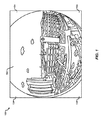
反射屈折カメラや魚眼レンズを有するカメラなどの全方向性カメラは、通常、ひずみの量が顕著な画像をキャプチャする。図1は、魚眼レンズを使用してキャプチャされたピクチャ100の一例を示す。魚眼レンズは、最大180度以上の視野を有することができる広角レンズである。背中合わせに配置されたそのような2つのレンズが装備されたカメラは、360度の(または、それを越える)視界を一緒に提供する2つの画像をそのようにキャプチャすることができる。
Omnidirectional cameras, such as catadioptric cameras and cameras with fisheye lenses, typically capture images with a significant amount of distortion. FIG. 1 shows an example of a
しかしながら、そのような広い視野を可能にするレンズの極端な曲率はまた、画像をひずんだ状態にさせる。図1の例において示すように、ピクチャ100の中にキャプチャされているシーン102は形状が円形であり、レンズの曲率にしたがってワープされる。カメラセンサは、通常、長方形であるので、ピクチャ100は長方形であり、ピクセルがキャプチャされなかった隅角部104は、通常は空白または黒色である。この例では、シーン102の上部および下部は切り取られている。シーン102の上部および下部は、様々な理由のために切り取ることができる。例示的な一例では、シーン102の上部および下部は、レンズの形状および/またはカメラセンサの形状に起因して切り取ることができる。
However, the extreme curvature of the lens that allows such a wide field of view also makes the image distorted. As shown in the example of FIG. 1, the
例示的な画像100は、大量の情報、この場合180度の視野をキャプチャする。他の画像は、270度の視界などの180度よりも大きくキャプチャすることができる。しかしながら、シーン102のひずみは、極めて現実的なプレゼンテーションを観察者に提供するとは限らない。追加として、画像100は、3次元シーンの平坦な2次元表現である。360度ビデオとしてのプレゼンテーションのために、画像100は、球状の3次元(3D)表現にマッピングされる必要がある。
The
様々な実装形態では、魚眼画像の中に存在するひずみを補正するとともに360度ビデオとしての表示のために画像をレンダリングするためのシステムおよび方法が提供される。様々な実装形態では、コンピューティングデバイスは、全方向性カメラによってキャプチャされた2次元ビデオデータを受信することができる。コンピューティングデバイスは、各ビデオフレームから3次元半球状表現に画像をマッピングすることができる。様々な実装形態では、このマッピングは、多項式モデルを使用して実行することができる。3次元半球状表現は、次いで仮想現実体験をもたらすために360度ビデオプレゼンテーションにおいて使用することができる。 In various implementations, systems and methods are provided for correcting distortion present in fisheye images and rendering the images for display as 360 degree video. In various implementations, a computing device can receive 2D video data captured by an omnidirectional camera. The computing device can map an image from each video frame to a three-dimensional hemispherical representation. In various implementations, this mapping can be performed using a polynomial model. The 3D hemispherical representation can then be used in a 360 degree video presentation to provide a virtual reality experience.
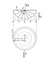
図2Aおよび図2Bは、本明細書で説明する技法の例示的な適用例を示す。図2Aの例は、全方向性カメラによってキャプチャできる画像200を示す。上記で説明したように、画像200は形状が長方形であり、ここで長方形の形状はカメラの画像キャプチャセンサのサイズおよび形状に対応する。画像200は、シーンをキャプチャするピクセルを含む円形領域202を含む。ピクセルがキャプチャされなかった画像200の隅角部204は、空白のままにされること、または黒色ピクセルを含むことが可能である(たとえば、0または255というピクセル値を有する)。
2A and 2B illustrate an exemplary application of the techniques described herein. The example of FIG. 2A shows an
円形領域202の中でキャプチャされたピクセルはいくつかの視野を含み、ここで視野はレンズおよび/またはカメラによって規定される。たとえば、円形領域202は、カメラのレンズ、ミラー、および/またはセンサの構成に応じて、90度の視野、180度の視野、270度の視野、またはいくつかの他の程度の視野を含むことができる。視野を画像200の中に合わせるために、ピクセルは、以下でさらに説明するように直線的または非直線的に円形領域202の中へワープされる。
The pixels captured in the
様々な実装形態では、以下で説明する技法は、円形領域202の中のピクセルを半球状表現210にマッピングし、その一例が図2Bに示される。半球状表現210は、次いで仮想現実レンダリングデバイスを使用する観察者に画像200を提示するために使用することができる。半球状表現210は、球体のうちの半分であること(180度の視界を表す)、球体のうちの半分よりも小さいこと(たとえば、画像200が180度よりも小さい視界をキャプチャするとき)、または球体のうちの半分よりも大きいこと(たとえば、画像200が180度よりも大きい視界をキャプチャするとき)が可能である。
In various implementations, the techniques described below map the pixels in the
様々な実装形態では、以下で説明する技法は、円形領域202の中のピクセルを半球状の形状の中へ伸張する効果がある。たとえば、円形領域202の中心212は、半球状表現210の中心222すなわち頂点に対応することができる。さらなる例として、円形領域202の一番上の点214aは半球状表現210の一番上の点224a(たとえば、北極(polar north))に対応することができ、円形領域202の一番下の点214bは半球状表現210の一番下の点224b(たとえば、南極(polar south))に対応することができる。同様に、円形領域202の一番右214cおよび一番左214dは、この例では半球状表現210の一番右224cおよび見えていない一番左224dとなるものに対応することができる。円形領域202の中心212と縁部との中間のピクセルは、さらに半球状表現210の表面にわたって均等に分散することができる。
In various implementations, the techniques described below have the effect of stretching the pixels in the
得られた半球状表現210は、平坦な画像200を360度表示で提示するために使用することができる。図3は、半球状表現310の例示的な使用を示す。360度ディスプレイデバイスを使用すると、半球状表現310は、観察者320にその人が半球状表現310によってキャプチャされたピクセルによって表されるシーンの内側にいるという印象が与えられるようにレンダリングすることができる。場合によっては、半球状表現310の頂点は、観察者の視野の中心にあるように向けることができる。様々な実装形態では、観察者320の後ろにあることになる視界のために追加の半球状表現が設けられることが可能である。
The resulting
様々なタイプの魚眼レンズがあり、その各々は異なる方法で広角度の視野を画像平面にマッピングする。一例は、fシータレンズ(f-theta lens)とも呼ばれるアンギュラ魚眼レンズである。アンギュラ魚眼レンズを用いると、画像の中心からの距離は、カメラ視界方向からの角度に比例する。その結果、解像度は画像全体にわたってほぼ等しい。アンギュラ魚眼レンズは、完全な360度いっぱいの角度に対して使用することができる。 There are various types of fisheye lenses, each of which maps a wide angle field of view to the image plane in different ways. An example is an angular fish-eye lens, also called an f-theta lens. When an angular fisheye lens is used, the distance from the center of the image is proportional to the angle from the camera view direction. As a result, the resolution is approximately equal across the entire image. Angular fisheye lenses can be used for full 360 degree full angles.
図4は、180度アンギュラ魚眼レンズ420の横断面、およびレンズ420のための対応する画像平面402の一例を示す。図は、レンズの画像平面402に垂直な側部から見たときのレンズ420を示す。示される図はまた、レンズ420の上面図、またはレンズの画像平面402と垂直な任意の他の角度からの図であることが可能であるが、この例では図4が側面図を示すと想定する。レンズの画像平面402の正面図が図4の左側に示される。
FIG. 4 shows an example of a cross section of a 180 degree
アンギュラレンズの構成は、0からの任意の角度に対して(ただし、0はレンズ420の中心(カメラ位置406とも見なされる)である)、その角度においてキャプチャされる空間の中の点が画像平面402の中の点ρに直線的に対応するようなものである。すなわち、たとえば0からのα=45度において、レンズ420に入る光は画像平面402の中心と画像平面402の上部との間の中間の点においてキャプチャされる。画像平面402の上部は、α=90度にスケーリング係数または拡大係数を掛けたものに対応する。同様に、0からのα=22.5度において、レンズに入る光は画像平面402の中で、ρ=0と、45度としてキャプチャされるピクセルとの間の中間でキャプチャされ、0からの67.5度において、光は画像平面402の中で45度と画像平面402の上部との間の中間でキャプチャされる。この例ではレンズ420が側部から見られていることが想定されるので、画像平面402の中心からρの距離は垂直方向にのみ変化する。
Angular lens configuration is for any angle from 0, where 0 is the center of lens 420 (also considered camera position 406), and the point in space captured at that angle is the image plane It corresponds to a point ρ in 402 linearly. That is, for example, at α = 45 degrees from 0,
図4の例示的なレンズ420によって生成される画像平面402は、半球にマッピングすることができ、ここで半球はコンピューティングデバイスにおいて3次元メッシュを使用して表すことができる。たとえば、画像平面402からの円形画像は、グラフィックス処理装置(GPU)を使用してレンダリングすることができる。画像を半球にマッピングすることは、レンズ420が生み出す固有のひずみを矯正することができる。このマッピングのための技法は、以下でさらに説明される。
The
他のタイプの魚眼レンズは、レンズの中心から画像の外縁部まで非直線ひずみを生み出す。図5は、半球状魚眼レンズ520の一例を示す。レンズ520の側面図が図の右側に示され、レンズのための画像平面502の正面図が図の左側に示される。
Other types of fisheye lenses produce nonlinear distortion from the center of the lens to the outer edge of the image. FIG. 5 shows an example of a
半球状レンズは、画像平面502上への半球の平行投影を生み出す。このおよび他の例では、画像は半径方向に圧縮された状態になり、レンズのより外側の縁部に向かってより大きい圧縮が発生する。すなわち、角度αが0から増大するにつれて(ただし、0はレンズ520の中心(カメラ位置506とも見なされる)である)、画像平面502の中でキャプチャされる画像は、非直線的にますます圧縮された状態になる。これらのタイプのレンズによってキャプチャされる画像は、ひずみの非直線性が補正される必要がある。
The hemispherical lens produces a parallel projection of the hemisphere onto the
様々な実装形態では、キャプチャされた画像の中に魚眼投影が持ち込むことができる非直線ひずみを補正するために、以下で説明する技法が使用されることが可能である。様々な実装形態では、これらの技法は、多項式モデルを採用する全方向性カメラ較正技法を使用することを含む。全方向性カメラ較正技法は、参照によりその全体が本明細書に組み込まれる、Davide Scaramuzzaらの"A Flexible Technique for Accurate Omnidirectional Camera Calibration and Structure from Motion"において説明されている。全方向性カメラ(反射屈折カメラおよび光屈折カメラを含む)がこの技法にしたがって較正されていると、実世界における点は、カメラのセンサによってキャプチャされたピクセルごとに決定することができる。 In various implementations, the techniques described below can be used to correct for non-linear distortion that a fisheye projection can bring into the captured image. In various implementations, these techniques include using omnidirectional camera calibration techniques that employ polynomial models. The omnidirectional camera calibration technique is described in David Scaramuzza et al. "A Flexible Technique for Accurate Omnidirectional Camera Calibration and Structure from Motion", which is incorporated herein by reference in its entirety. When omnidirectional cameras (including catadioptric and photorefractive cameras) are calibrated according to this technique, a point in the real world can be determined for each pixel captured by the camera sensor.
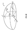
図6Aは、全方向性カメラによってキャプチャできる画像602の一例を示す。上記で説明したように、画像602は、魚眼ひずみを有することができ、ここで画像の中でキャプチャされたシーンは、円形の形状にワープされている。画像602を半球状表現610にマッピングするために、画像の水平軸はuと標示され、垂直軸はvと標示される。水平寸法と垂直寸法の両方に対して0は画像602の中心に位置する。この例では、ρは画像602によって形成される円の半径に沿った点として規定される。そのような点604は座標(u,v)を有することができる。
FIG. 6A shows an example of an
図6Bは、画像602の中にキャプチャされたシーンがそこにマッピングされるべき半球状表現610の一例を示す。このマッピングのために、直交のX軸およびY軸が規定される。様々な実装形態では、X軸は、たとえば実世界における上下に対応することができ、Y軸は左右に対応することができる。Z軸は、カメラのイメージセンサに垂直であるように規定される。半球状表現610の表面上の点614は、座標(x,y,z)を使用して表すことができる。点614はまた、X軸とY軸との間での点の回転を表す、対応する角度値Φを有することができる。点614はまた、Z軸とX軸およびY軸によって形成される平面との間での点の回転を表す、角度値rを有することができる。
FIG. 6B shows an example of a
様々な実装形態では、上述の全方向性カメラ較正方法は、画像602の中の点604の位置(u,v)をセンサ軸に対して(すなわち、図6Bに示すZ軸に対して)点614に関係付けるために、以下の多項式を使用する。
f(ρ)=a0+a1ρ+a2ρ2+…+aNρN
In various implementations, the omnidirectional camera calibration method described above points the position (u, v) of
f (ρ) = a 0 + a 1 ρ + a 2 ρ 2 +… + a N ρ N
上式において、係数ai(i=0,1,2,...N)および多項式次数Nは、較正によって決定されるモデルパラメータであり、ρは、上記で説明したように半径方向値と呼ばれることがあるセンサ軸からの距離である。 Where the coefficients a i (i = 0,1,2, ... N) and the polynomial order N are model parameters determined by calibration, and ρ is the radial value as described above. The distance from the sensor axis that may be called.
カメラ較正は、一般に特定のカメラ用の固有パラメータおよび外部パラメータを決定することを伴う。カメラの固有パラメータは、カメラの焦点距離および光心を含む。上式において、係数aiは画像602の形状を表す固有パラメータである。外部パラメータは、地上に対する回転の程度(たとえば、ピッチ、ヨー、および/またはロール)、およびカメラの3次元の実世界ロケーションを含むことができる(カメラの「トランスレーション(translation)」と呼ばれる)。外部パラメータは、一般にカメラのセンサの中心から測定される。カメラ較正は、一般にカメラの固有パラメータおよび外部パラメータを決定することを伴う。様々な実装形態では、これは自動的に、かつ/または較正パターンをキャプチャする画像の支援を伴って達成することができる。
Camera calibration generally involves determining intrinsic and extrinsic parameters for a particular camera. The intrinsic parameters of the camera include the camera focal length and optical center. In the above equation, the coefficient a i is a unique parameter representing the shape of the
上記の関数f(ρ)は、画像602が回転的に均一であると想定し、そのことは、画像602の中心からの所与の距離に対して画像602の中のその距離におけるすべての点が、カメラセンサから等距離の空間における点をキャプチャすることを意味する。カメラレンズが通常は精密に対称的であるように製造されるので、このことは妥当な想定である。関数は、円形の魚眼画像602を半球状表現610上にマッピングするために、そのように使用することができる。上述のように、関数は、画像602の中の座標を半球状表現610のZ軸に対して対応する点に関係付ける。したがって、半球状表現610上の任意の点614に対して、関数は、画像602の中の対応する点604を見つけるために使用することができる。ピクセルは、次いで画像602の中の点604から採ることができ、半球状表現610における対応する点614に配置することができる。
The above function f (ρ) assumes that
図6Aにおける画像602が(図4の例で説明したような)直線ひずみを含むとき、半球状表現610における点614(回転座標(r,Φ)とともに座標(x,y,z)を有する)に対して、対応する点604(画像平面602の中の座標(u,v)を有する)は、次の式を使用して決定することができる。

上式において、uおよびvは正規化され、そのことは、uおよびvが各々0〜1の間で変化することを意味する。 In the above equation, u and v are normalized, which means that u and v each vary between 0 and 1.
回転座標(r,Φ)は、関数atan2を使用して決定することができる。atan2関数は、2つの引数を有する逆正接関数であり、両方が0に等しいわけではない任意の実数引数xおよびyに対して、atan2(y,x)は、平面の正のx軸と座標(x,y)によって与えられる平面上の点との間の角度をラジアン単位で戻す。角度は、反時計回りの角度(たとえば、y>0である平面の上半分)に対して正であり、時計回りの角度(たとえば、y<0である平面の下半分)に対して負である。atan2を使用すると、rおよびΦは次のように計算することができる。
上式において、rは0から1まで変動し、Φは0から2πまで変動する。 In the above equation, r varies from 0 to 1, and Φ varies from 0 to 2π.
上式を使用すると、画像602からのピクセルは、半球状表現610にマッピングすることができる。具体的には、座標(x,y,z)を有する所与の点614に対して、画像602の中の座標(u,v)を有する対応する点604が計算されることが可能である。ピクセルは、次いで画像602の中の点604から採ることができ、半球状表現において(x,y,z)に配置することができる。
Using the above equation, pixels from
画像602が(図5の例で説明したような)非直線ひずみを含むとき、画像602(図6Aに示すような)を半球状表現610にマッピングするために、以下の追加および/または代替の計算が使用されることが可能である。これらの式は、非直線ひずみを補正することができる。以下の説明では、非直線ひずみを含む画像602の中の点に対して、補正済み正規化座標と呼ばれることがあるu'およびv'が、これらの点に対する座標を表すために使用される。
When
上述のように、画像602の中心からの距離ρは非直線的に変化する。ρの値は次のように表現することができる。
ρ=k0r
As described above, the distance ρ from the center of the
ρ = k 0 r
上式において、角度値rは上記で説明したように計算することができる。 In the above equation, the angle value r can be calculated as described above.
関数f(ρ)は、さらに次のように修正することができる。
f(ρ)=k1(a0+a1ρ+a2ρ2+…+aNρN)
The function f (ρ) can be further modified as follows.
f (ρ) = k 1 (a 0 + a 1 ρ + a 2 ρ 2 +… + a N ρ N )
上の2つの式において、k0およびk1はスケーリングパラメータであり、aiは上記で説明したようにカメラ較正によって決定された係数である。関数f(ρ)は座標(x,y,z)を有する点614のセンサ軸Z上への投影を行う。関数f(ρ)の結果はそのようにz座標を与える。 In the above two equations, k 0 and k 1 are scaling parameters, and a i are coefficients determined by camera calibration as described above. The function f (ρ) projects a point 614 having coordinates (x, y, z) onto the sensor axis Z. The result of the function f (ρ) thus gives the z coordinate.
パラメータk0はrをρにスケーリングし、すなわちk0はρの非直線的な変動にしたがってrを調整する。パラメータk0は、図5に関して上記で説明したような魚眼画像における非直線的な圧縮に対して多項式を調整するためにそのように使用することができる。パラメータk0に対する値は、rおよび関数f(ρ)から導出することができる。具体的には、k0はr=1のときにf(ρ)=0となるように決定することができる。図6Bに示すように、r=1は、画像602がそこにマッピングされている半球状表現610の末端の縁部である。半球状表現610の縁部において、z座標は0であり、したがって(z座標を与える)f(ρ)もまた0である。
The parameter k 0 scales r to ρ, ie k 0 adjusts r according to the non-linear variation of ρ. The parameter k 0 can be used as such to adjust the polynomial for non-linear compression in fisheye images as described above with respect to FIG. The value for the parameter k 0 can be derived from r and the function f (ρ). Specifically, k 0 can be determined so that f (ρ) = 0 when r = 1. As shown in FIG. 6B, r = 1 is the end edge of the
パラメータk1はf(ρ)をzにスケーリングする。関数f(ρ)を導出するために使用されるカメラ較正方法は半球状の投影を想定し、ただしf(ρ)<0である。したがって、k1は-1などの負の値に設定することができ、その結果f(ρ)は正の値を生み出す。代替として、係数aiの符号は変化させることが可能である。代替として、場合によっては符号変化は以下で説明する式の中に含められてよい。 The parameter k 1 scales f (ρ) to z. The camera calibration method used to derive the function f (ρ) assumes a hemispherical projection, where f (ρ) <0. Thus, k 1 can be set to a negative value, such as -1, so that f (ρ) produces a positive value. Alternatively, the sign of the coefficient a i can be changed. Alternatively, in some cases the sign change may be included in the equations described below.
画像平面602の中の点(u',v')に対する座標は、次式を使用して決定することができる。
上式において、u'およびv'は正規化され、0〜1の間で変化する。 In the above equation, u ′ and v ′ are normalized and vary between 0 and 1.
上式について、r'は次のように計算することができる。
上式を使用すると、半径方向のひずみは、〜ここで画像の中心からの距離が増大するにつれて画像602はますます大きい圧縮を受ける〜画像が半球状表現610にマッピングされるときに補正することができる。具体的には、半球状表現610上の点614(x,y,z)に対して、画像の中の座標(u',v')を有する点を決定することができる。点(u',v')からのピクセルは、次いで点614(x,y,z)に配置することができる。
Using the above equation, radial distortion can now be corrected when the image is mapped to the
場合によっては、追加のスケーリング係数が必要とされてよい。たとえば、画像が180度よりも大きいかもしくは180度よりも小さい視野を含み、かつ/または視野の一部分が切り取られているとき、視野および/またはクロッピングに適応するようにスケーリング係数αおよびβが導入されることが可能である(切り取られた魚眼画像の一例については図1を参照)。視野が、たとえばすべての方向において220度のような対称であるとき、αおよびβは同じであることが可能である(たとえば、両方が180/220に等しい)。視野が非対称であるとき、αおよび/またはβは非対称性に適応する値に設定することができる。たとえば、図1の例では視野が180度であると想定すると、βは1に設定することができ、αは180/nに設定することができ、ただしnは画像の中心からフレームの切り取られた上縁部または下縁部までの距離である。 In some cases, additional scaling factors may be required. For example, when the image includes a field of view greater than 180 degrees or smaller than 180 degrees and / or a portion of the field of view is cropped, scaling factors α and β are introduced to accommodate field of view and / or cropping (See FIG. 1 for an example of a cropped fisheye image). When the field of view is symmetric, such as 220 degrees in all directions, α and β can be the same (eg, both are equal to 180/220). When the field of view is asymmetric, α and / or β can be set to a value that accommodates asymmetry. For example, in the example of FIG. 1, assuming that the field of view is 180 degrees, β can be set to 1 and α can be set to 180 / n, where n is clipped from the center of the image. The distance to the upper edge or the lower edge.
αおよびβを用いると、(u'',v'')として表現される画像602の中の点を決定するための式は、次式を使用して決定することができる。
上式において、r'は上記で説明したように決定することができる。 In the above equation, r ′ can be determined as described above.
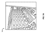
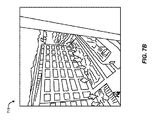
図7Aおよび図7Bは、補正を用いてレンダリングされた画像および補正を用いずにレンダリングされた画像の例を示す。図7Aの例では、画像702は、カメラによって引き起こされたひずみに対するいかなる補正も用いずに全方向性カメラによってキャプチャされたものとしてレンダリングされる。この例によって示されるように、シーンの中の建物および通路がまっすぐであるのではなく消失点に向かって曲がるように画像702はワープされる。
7A and 7B show examples of an image rendered with correction and an image rendered without correction. In the example of FIG. 7A, the
図7Bの例では、画像710は、上記で説明した技法を使用してレンダリングされる。この例示的な画像710では、建物および建物の正面の通路の縁部は、実世界において出現することになるようにまっすぐである。例示的な画像710は、明快のためかつ理解しやすいように、ここでは2次元かつ形状が長方形として示される。例示的な画像710は、上記のように3次元半球状表現にレンダリングされており、取得された補正がここで図示される。
In the example of FIG. 7B, the
様々な実装形態では、上記で説明した多項式モデルに関連するパラメータの一部または全部は、全方向性カメラを使用してキャプチャされた画像データとともに伝達することができる。これらのパラメータは、特に多項式係数ai(i=0,1,2,...N)、多項式次数N、スケーリングパラメータk0、k1、ならびに/またはスケーリングパラメータαおよびβを含む。ビデオデータに含まれるとき、これらのパラメータは、次いでビデオフレームの中の魚眼画像を360度ビデオプレゼンテーション用の半球状表現にレンダリングするために使用することができる。いくつかの実装形態では、パラメータは、カメラによってキャプチャされた2次元画像を3次元表現にマッピングするためにビデオキャプチャデバイスにおいて使用することができる。3次元表現は、次いで記憶および/または送信のために符号化することができる。いくつかの実装形態では、2次元画像は、記憶および/または送信のために符号化することができ、レシーバデバイスは、360度ビデオプレゼンテーション向けに画像をレンダリングするために画像を復号するとともにパラメータを使用することができる。 In various implementations, some or all of the parameters associated with the polynomial model described above can be communicated along with image data captured using an omnidirectional camera. These parameters include in particular the polynomial coefficients a i (i = 0,1,2,... N), the polynomial order N, the scaling parameters k 0 , k 1 and / or the scaling parameters α and β. When included in the video data, these parameters can then be used to render the fisheye image in the video frame into a hemispherical representation for a 360 degree video presentation. In some implementations, the parameters can be used in a video capture device to map a 2D image captured by a camera to a 3D representation. The three-dimensional representation can then be encoded for storage and / or transmission. In some implementations, the two-dimensional image can be encoded for storage and / or transmission, and the receiver device decodes the image and renders the parameters to render the image for a 360 degree video presentation. Can be used.
モデルパラメータを伝達するために、様々な方法が使用されることが可能である。たとえば、パラメータは、ビットストリームの構文的な構造を使用してビデオビットストリームの中に含めることができる。たとえば、パラメータは、1つまたは複数の補足エンハンスメント情報(SEI)メッセージの中に含めることができる。別の例として、パラメータは、360度ビデオを記憶するために使用されるファイルフォーマットの中へ組み込むことができる。別の例として、パラメータは、特別なネットワークプロトコル拡張の中へ組み込むことができる。 Various methods can be used to communicate model parameters. For example, the parameters can be included in the video bitstream using the syntactic structure of the bitstream. For example, the parameters can be included in one or more supplemental enhancement information (SEI) messages. As another example, the parameters can be incorporated into a file format used to store 360 degree video. As another example, the parameters can be incorporated into special network protocol extensions.
様々な実装形態では、同じ結果を達成するために、上記で説明した多項式モデルの代替形態を使用することができる。たとえば、代替のパラメータを使用する区分線形モデルなどの多項式モデルの近似も使用することができる。 In various implementations, an alternative form of the polynomial model described above can be used to achieve the same result. For example, approximations of polynomial models such as piecewise linear models using alternative parameters can also be used.
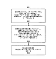
図8は、360度ビデオプレゼンテーションにおける表示のために、2次元魚眼画像を3次元半球状表現にマッピングするためのプロセス800の一例を示すフローチャートである。802において、プロセス800は、全方向性カメラによってキャプチャされた2次元ビデオデータを取得することを含み、2次元ビデオデータはシーンの画像を含み、画像の中で、シーンは画像の円形領域の中へワープされている。いくつかの実装形態では、ワープは半径方向に直線的であってよく、すなわち画像は円形領域の中心から外縁部まで一様にゆがむ。場合によっては、画像が、中心において存在するよりも大きい圧縮を円形領域の外縁部に向かって含むようにワープは非直線的であってよい。
FIG. 8 is a flowchart illustrating an example of a
いくつかの実装形態では、ビデオデータは、符号化ビットストリームから取得される。これらの実装形態では、符号化ビットストリームは、画像のワープを記述するパラメータを含むことができる。これらのパラメータは、たとえば特に多項式次数、多項式係数、多項式スケーリングパラメータ、またはマッピングスケーリングパラメータを含むことができる。いくつかの実装形態では、パラメータは、符号化ビットストリームの中のSEIメッセージから取得することができる。いくつかの実装形態では、パラメータは、符号化ビットストリームを含むファイルの中に含まれることが可能である。これらの実装形態では、ファイルは、パラメータを記憶するためのデータ構造を含むことができる。 In some implementations, video data is obtained from an encoded bitstream. In these implementations, the encoded bitstream may include parameters that describe the warp of the image. These parameters can include, for example, polynomial order, polynomial coefficients, polynomial scaling parameters, or mapping scaling parameters, among others. In some implementations, the parameters can be obtained from SEI messages in the encoded bitstream. In some implementations, the parameters can be included in a file that includes the encoded bitstream. In these implementations, the file can include a data structure for storing parameters.
804において、プロセス800は、画像を3次元半球状表現にマッピングすることを含み、画像をマッピングすることは、画像の円形領域の中のピクセルを3次元半球状表現上の対応するロケーションにマッピングすることを含み、画像をマッピングすることは、シーンのワープを補正する。いくつかの実装形態では、画像をマッピングすることは、画像の中の点を3次元半球状表現上の対応する点に投影するための多項式を使用することを含む。画像の中の点は、3次元半球状表現上の点にマッピングすべきピクセルを提供することができる。
At 804,
いくつかの実装形態では、円形領域の中への画像のワープは非直線的であってよい。これらの実装形態では、画像を3次元半球状表現にマッピングすることは、調整された半径方向値を使用して2次元画像の中のピクセルに対する座標を決定することを含むことができる。調整された半径方向値は、ワープの非直線性に対応することができる。たとえば、調整された半径方向値は、画像の中心から外縁部まで非直線的に増大する。調整された半径方向値を使用して決定された座標は、次いで画像から半球状表現にピクセルをマッピングするために使用することができる。 In some implementations, the warp of the image into the circular region may be non-linear. In these implementations, mapping the image to the three-dimensional hemispherical representation can include determining coordinates for pixels in the two-dimensional image using the adjusted radial values. The adjusted radial value can correspond to the non-linearity of the warp. For example, the adjusted radial value increases non-linearly from the center of the image to the outer edge. The coordinates determined using the adjusted radial values can then be used to map the pixels from the image to the hemispherical representation.
いくつかの実装形態では、画像は、180度よりも大きい視野を含む。これらの実装形態では、プロセス800は、視野にしたがってスケーリングされている半径方向値を使用して2次元画像の中のピクセルに対する座標をしたがって調整することをさらに含む。座標は、次いで画像から半球状表現にピクセルをマッピングするために使用することができる。いくつかの実装形態では、画像は180度以下の視野を含む。
In some implementations, the image includes a field of view greater than 180 degrees. In these implementations, the
806において、プロセスは、3次元半球状表現を360度ビデオプレゼンテーションにおいて使用することを含む。たとえば、3次元半球状表現は、ビデオディスプレイデバイスによる表示のためにレンダリングすることができる。代替または追加として、3次元半球状表現は、記憶および/または送信のために符号化することができ、ここで符号化データは、後で復号および表示することができる。 At 806, the process includes using a three-dimensional hemispherical representation in a 360 degree video presentation. For example, a three-dimensional hemispherical representation can be rendered for display by a video display device. Alternatively or additionally, the three-dimensional hemispherical representation can be encoded for storage and / or transmission, where the encoded data can be decoded and displayed later.
いくつかの実装形態では、プロセス800は、スマートフォン、タブレットコンピュータ、ラップトップコンピュータ、携帯情報端末、あるいはワイヤレスをネットワークに接続することができ、かつ/または容易にトランスポートされるのに十分に小型かつ軽量である任意の他の種類のコンピューティングデバイスなどのモバイルデバイスにおいて実施されることが可能である。これらの実装形態では、モバイルデバイスは、360度ビデオをキャプチャするための全方向性カメラを含むことができる。いくつかの実装形態では、モバイルデバイスは、360度ビデオを表示するためのディスプレイを含むことができる。
In some implementations, the
いくつかの例では、プロセス800は、図9に関して以下で説明するシステムなどのコンピューティングデバイスまたは装置によって実行されてよい。たとえば、プロセス800は、図9に示すシステム900および/またはストレージ908もしくは出力部910によって実行することができる。場合によっては、コンピューティングデバイスまたは装置は、図8のプロセス800のステップを実行するように構成されているデバイスのプロセッサ、マイクロプロセッサ、マイクロコンピュータ、または他の構成要素を含んでよい。いくつかの例では、コンピューティングデバイスまたは装置は、ビデオフレームを含むビデオデータ(たとえば、ビデオシーケンス)をキャプチャするように構成されるカメラを含んでよい。たとえば、コンピューティングデバイスは、ビデオコーデックを含んでよいカメラデバイス(たとえば、全方向性カメラ、または他のタイプのカメラデバイス)を含んでよい。いくつかの例では、ビデオデータをキャプチャするカメラまたは他のキャプチャデバイスは、コンピューティングデバイスとは別個であり、その場合、コンピューティングデバイスは、キャプチャされたビデオデータを受信する。コンピューティングデバイスは、ビデオデータを通信するように構成されるネットワークインターフェースをさらに含んでもよい。ネットワークインターフェースは、インターネットプロトコル(IP)ベースのデータまたは任意の他の好適なタイプのデータを通信するように構成されてよい。
In some examples,
プロセス800は、論理フロー図として図示され、その動作は、ハードウェア、コンピュータ命令、またはそれらの組合せで実施されてもよい動作のシーケンスを表す。コンピュータ命令のコンテキストでは、動作は、1つまたは複数のプロセッサによって実行されたとき、説明する動作を実行する1つまたは複数のコンピュータ可読記憶媒体に記憶されたコンピュータ実行可能命令を表す。一般的に、コンピュータ実行可能命令は、特定の機能を実行し、または特定のデータタイプを実装する、ルーチン、プログラム、オブジェクト、コンポーネント、データ構造などを含む。動作が説明される順序は、限定として解釈されることを意図せず、説明される任意の数の動作は、プロセスを実施するために任意の順序で、かつ/または並列に組み合わせられてよい。
追加として、プロセス800は、実行可能命令とともに構成される1つまたは複数のコンピュータシステムの制御下で実行されてよく、ハードウェアまたはその組合せによって1つまたは複数のプロセッサ上で集合的に実行するコード(たとえば、実行可能命令、1つもしくは複数のコンピュータプログラム、または1つもしくは複数のアプリケーション)として実装されてよい。上述のように、コードは、たとえば1つまたは複数のプロセッサによって実行可能な複数の命令を備えるコンピュータプログラムの形態で、コンピュータ可読記憶媒体または機械可読記憶媒体に記憶されてもよい。コンピュータ可読記憶媒体または機械可読記憶媒体は非一時的であってよい。
Additionally,
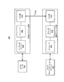
図9は、符号化デバイス904および復号デバイス912を含むシステム900の一例を示すブロック図である。符号化デバイス904はソースデバイスの一部であってよく、復号デバイス912は受信デバイスの一部であってよい。ソースデバイスおよび/または受信デバイスは、モバイルもしくは固定の電話ハンドセット(たとえば、スマートフォン、セルラー電話など)、デスクトップコンピュータ、ラップトップもしくはノートブックコンピュータ、タブレットコンピュータ、セットトップボックス、テレビジョン、カメラ、ディスプレイデバイス、デジタルメディアプレーヤ、ビデオゲームコンソール、ビデオストリーミングデバイス、または任意の他の適切な電子デバイスなどの電子デバイスを含んでもよい。いくつかの例では、ソースデバイスおよび受信デバイスは、ワイヤレス通信用の1つまたは複数のワイヤレストランシーバを含んでもよい。本明細書で説明するコーディング技法は、(たとえば、インターネットを介した)ストリーミングビデオ送信、テレビジョン放送もしくは送信、データ記憶媒体に記憶するためのデジタルビデオの符号化、データ記憶媒体に記憶されたデジタルビデオの復号、または他の適用例を含む様々なマルチメディア用途におけるビデオコーディングに適用可能である。いくつかの例では、システム900は、ビデオ会議、ビデオストリーミング、ビデオ再生、ビデオブロードキャスティング、ゲーミング、および/またはビデオ電話などの適用例をサポートするために一方向または双方向のビデオ送信をサポートすることができる。
FIG. 9 is a block diagram illustrating an example of a
符号化デバイス904(すなわち、エンコーダ)は、符号化ビデオビットストリームを生成するためのビデオコーディング規格またはビデオコーディングプロトコルを使用して仮想現実ビデオデータを含むビデオデータを符号化するために使用されてもよい。ビデオコーディング規格は、ITU-T H.261、ISO/IEC MPEG-1 Visual、ITU-T H.262またはISO/IEC MPEG-2 Visual、ITU-T H.263、それぞれ、SVCおよびMVCと呼ばれるそのスケーラブルビデオコーディングおよびマルチビュービデオコーディング拡張を含むISO/IEC MPEG-4 VisualおよびITU-T H.264(ISO/IEC MPEG-4 AVCとも呼ばれる)を含む。より最近のビデオコーディング規格、すなわち高効率ビデオコーディング(HEVC)が、ITU-Tビデオコーディングエキスパートグループ(VCEG:Video Coding Experts Group)とISO/IECムービングピクチャエキスパートグループ(MPEG)とのビデオコーディング共同研究部会(JCT-VC)によって確定された。MV-HEVCと呼ばれるHEVCのマルチビュー拡張、およびSHVCと呼ばれるHEVCのスケーラブル拡張、または任意の他の適切なコーディングプロトコルを含むHEVCの様々な拡張が、マルチレイヤビデオコーディングを扱い、同様にJCT-VCによって開発されている。 An encoding device 904 (i.e., an encoder) may be used to encode video data, including virtual reality video data, using a video coding standard or video coding protocol to generate an encoded video bitstream. Good. The video coding standards are ITU-T H.261, ISO / IEC MPEG-1 Visual, ITU-T H.262 or ISO / IEC MPEG-2 Visual, ITU-T H.263, respectively called SVC and MVC. Includes ISO / IEC MPEG-4 Visual and ITU-T H.264 (also called ISO / IEC MPEG-4 AVC) including scalable video coding and multi-view video coding extensions. A more recent video coding standard, namely High Efficiency Video Coding (HEVC), is a joint video coding research group between the ITU-T Video Coding Experts Group (VCEG) and ISO / IEC Moving Picture Experts Group (MPEG). Confirmed by (JCT-VC). Various extensions to HEVC, including a multi-view extension of HEVC called MV-HEVC, and a scalable extension of HEVC called SHVC, or any other suitable coding protocol, handle multi-layer video coding, as well as JCT-VC Developed by.
本明細書で説明する実装形態は、HEVC規格またはそれの拡張を使用する例を説明する。しかしながら、本明細書で説明する技法およびシステムはまた、AVC、MPEG、それらの拡張、あるいはすでに利用可能であるかまたはまだ利用可能もしくは開発済みでない他の適切なコーディング規格などの他のコーディング規格に適用可能であってもよい。したがって、本明細書で説明する技法およびシステムは特定のビデオコーディング規格を参照しながら説明されてもよいが、説明がその特定の規格だけに適用されるものと解釈されるべきでないことを当業者なら了解されよう。 The implementation described herein describes an example using the HEVC standard or an extension thereof. However, the techniques and systems described herein also apply to other coding standards such as AVC, MPEG, their extensions, or other suitable coding standards that are already available or not yet available or developed. It may be applicable. Thus, although the techniques and systems described herein may be described with reference to a particular video coding standard, those skilled in the art will understand that the description should not be construed to apply only to that particular standard. Then it will be understood.
ビデオソース902は、符号化デバイス904にビデオデータを提供してもよい。ビデオソース902は、ソースデバイスの一部であってよく、またはソースデバイス以外のデバイスの一部であってもよい。ビデオソース902は、ビデオキャプチャデバイス(たとえば、ビデオカメラ、カメラ付き携帯電話、ビデオ付き携帯電話など)、記憶されたビデオを含むビデオアーカイブ、ビデオデータを提供するビデオサーバもしくはコンテンツプロバイダ、ビデオサーバもしくはコンテンツプロバイダからビデオを受信するビデオフィードインターフェース、コンピュータグラフィックスビデオデータを生成するためのコンピュータグラフィックスシステム、そのようなソースの組合せ、または任意の他の適切なビデオソースを含んでもよい。ビデオソース902の一例は、インターネットプロトコルカメラ(IPカメラ)を含むことができる。IPカメラは、監視、ホームセキュリティ、または他の好適な適用例のために使用されてもよいタイプのデジタルビデオカメラである。アナログ閉回路テレビジョン(CCTV:closed circuit television)カメラとは異なり、IPカメラは、コンピュータネットワークおよびインターネットを経由してデータを送ることができ、または受信することができる。
ビデオソース902からのビデオデータは、1つまたは複数の入力ピクチャまたは入力フレームを含んでもよい。ピクチャまたはフレームは、ビデオの一部である静止画像である。符号化デバイス904のエンコーダエンジン906(または、エンコーダ)は、ビデオデータを符号化して符号化ビデオビットストリームを生成する。いくつかの例では、符号化ビデオビットストリーム(または、「ビデオビットストリーム」もしくは「ビットストリーム」)は、一連の1つまたは複数のコード化ビデオシーケンスである。コード化ビデオシーケンス(CVS:coded video sequence)は、ベースレイヤの中でいくつかの特性を伴うランダムアクセスポイントピクチャを有するアクセスユニット(AU:access unit)で開始し、ベースレイヤの中でいくつかの特性を伴うランダムアクセスポイントピクチャを有する次のAUの直前までの一連のAUを含む。たとえば、CVSを開始するランダムアクセスポイントピクチャのいくつかの特性は、1に等しいRASLフラグ(たとえば、NoRaslOutputFlag)を含んでもよい。そうでない場合、ランダムアクセスポイントピクチャ(0に等しいRASLフラグを有する)はCVSを開始しない。アクセスユニット(AU)は、1つまたは複数のコード化ピクチャ、および同じ出力時間を共有するコード化ピクチャに対応する制御情報を含む。ピクチャのコード化スライスは、ビットストリームレベルで、ネットワークアブストラクションレイヤ(NAL:network abstraction layer)ユニットと呼ばれるデータ単位の中にカプセル化される。たとえば、HEVCビデオビットストリームは、NALユニットを含む1つまたは複数のCVSを含んでもよい。ビデオコーディングレイヤ(VCL)NALユニットおよび非VCL NALユニットを含む、NALユニットの2つのクラスがHEVC規格に存在する。VCL NALユニットは、コード化ピクチャデータの1つのスライスまたはスライスセグメント(以下で説明する)を含み、非VCL NALユニットは、1つまたは複数のコード化ピクチャに関係する制御情報を含む。
Video data from
NALユニットは、ビデオの中のピクチャのコード化表現などのビデオデータのコード化表現(たとえば、符号化ビデオビットストリーム、ビットストリームのCVSなど)を形成するビットのシーケンスを含んでもよい。エンコーダエンジン906は、各ピクチャを複数のスライスに区分することによって、ピクチャのコード化表現を生成する。スライスは、次いでルーマサンプルおよびクロマサンプルのコーディングツリーブロック(CTB:coding tree block)に区分される。ルーマサンプルのCTB、およびクロマサンプルの1つまたは複数のCTBは、サンプル用のシンタックスとともにコーディングツリーユニット(CTU:coding tree unit)と呼ばれる。CTUは、HEVC符号化のための基本処理ユニットである。CTUは、様々なサイズの複数のコーディングユニット(CU:coding unit)に分割されてもよい。CUは、コーディングブロック(CB:coding block)と呼ばれるルーマサンプルアレイおよびクロマサンプルアレイを含む。
A NAL unit may include a sequence of bits that forms a coded representation of video data (eg, an encoded video bitstream, a bitstream CVS, etc.), such as a coded representation of a picture in a video. The
ルーマCBおよびクロマCBは、予測ブロック(PB:prediction block)にさらに分割されてもよい。PBは、インター予測のために同じ動きパラメータを使用するルーマまたはクロマ成分のサンプルのブロックである。ルーマPBおよび1つまたは複数のクロマPBは、関連するシンタックスとともに予測ユニット(PU:prediction unit)を形成する。動きパラメータのセットは、PUごとにビットストリームの中でシグナリングされ、ルーマPBおよび1つまたは複数のクロマPBのインター予測のために使用される。CBはまた、1つまたは複数の変換ブロック(TB:transform block)に区分されてもよい。TBは、予測残差信号をコーディングするために同じ2次元変換がそこに適用される、色成分のサンプルの正方形ブロックを表す。変換ユニット(TU:transform unit)は、ルーマサンプルおよびクロマサンプルのTB、ならびに対応するシンタックス要素を表す。 The luma CB and the chroma CB may be further divided into prediction blocks (PB). PB is a block of luma or chroma component samples that use the same motion parameters for inter prediction. The luma PB and one or more chroma PBs form a prediction unit (PU) with associated syntax. The set of motion parameters is signaled in the bitstream for each PU and used for inter prediction of luma PB and one or more chroma PBs. The CB may also be partitioned into one or more transform blocks (TB). TB represents a square block of samples of color components to which the same two-dimensional transform is applied to code the prediction residual signal. A transform unit (TU) represents a TB of luma samples and chroma samples, and corresponding syntax elements.
CUのサイズは、コーディングノードのサイズに対応し、形状が正方形であってもよい。たとえば、CUのサイズは、8×8サンプル、16×16サンプル、32×32サンプル、64×64サンプル、または対応するCTUのサイズまでの任意の他の適切なサイズであってよい。本明細書では、"N×N"という句は、垂直寸法および水平寸法に関してビデオブロックのピクセル寸法(たとえば、8ピクセル×8ピクセル)を指すために使用される。ブロックの中のピクセルは、行および列をなして配置されてよい。いくつかの実施形態では、ブロックは、水平方向において垂直方向と同じ数のピクセルを有しなくてよい。CUに関連するシンタックスデータは、たとえば1つまたは複数のPUへのCUの区分を記述してもよい。区分モードは、CUがイントラ予測モード符号化されるのか、それともインター予測モード符号化されるのかの間で異なる場合がある。PUは、形状が非正方形であるように区分されてよい。CUに関連するシンタックスデータはまた、たとえばCTUによる1つまたは複数のTUへのCUの区分を記述してもよい。TUは、形状が正方形または非正方形であってよい。 The size of the CU corresponds to the size of the coding node, and the shape may be square. For example, the size of the CU may be 8 × 8 samples, 16 × 16 samples, 32 × 32 samples, 64 × 64 samples, or any other suitable size up to the corresponding CTU size. As used herein, the phrase “N × N” is used to refer to the pixel dimensions of a video block (eg, 8 pixels × 8 pixels) with respect to vertical and horizontal dimensions. The pixels in the block may be arranged in rows and columns. In some embodiments, the block may not have the same number of pixels in the horizontal direction as in the vertical direction. The syntax data associated with a CU may describe a partition of the CU into one or more PUs, for example. The partition mode may differ between whether the CU is intra prediction mode encoded or inter prediction mode encoded. The PU may be partitioned so that the shape is non-square. The syntax data associated with the CU may also describe the partitioning of the CU into one or more TUs, for example by CTU. The TU may be square or non-square in shape.
HEVC規格によれば、変換は、変換ユニット(TU)を使用して実行されてもよい。TUは、異なるCUに対して異なってよい。TUは、所与のCU内のPUのサイズに基づいてサイズ決定されてもよい。TUは、同じサイズであってよく、またはPUより小さくてよい。いくつかの例では、CUに対応する残差サンプルは、残差4分木(RQT:residual quad tree)と呼ばれる4分木構造を使用して、より小さいユニットに再分割されてもよい。RQTのリーフノードは、TUに対応してもよい。TUに関連するピクセル差分値は、変換係数を生成するように変換されてもよい。変換係数は、次いでエンコーダエンジン906によって量子化されてもよい。
According to the HEVC standard, the conversion may be performed using a conversion unit (TU). The TU may be different for different CUs. The TU may be sized based on the size of the PU in a given CU. The TU can be the same size or smaller than the PU. In some examples, residual samples corresponding to a CU may be subdivided into smaller units using a quadtree structure called a residual quad tree (RQT). The leaf node of RQT may correspond to TU. The pixel difference value associated with the TU may be transformed to generate a transform coefficient. The transform coefficients may then be quantized by
ビデオデータのピクチャがCUに区分されると、エンコーダエンジン906は、予測モードを使用して各PUを予測する。予測は、次いで残差(以下で説明する)を得るために元のビデオデータから減算される。CUごとに、予測モードが、シンタックスデータを使用してビットストリームの内部でシグナリングされてもよい。予測モードは、イントラ予測(または、イントラピクチャ予測)またはインター予測(または、インターピクチャ予測)を含んでもよい。イントラ予測を使用すると、たとえばPUにとっての平均値を見つけるためのDC予測、平坦面をPUに適合させるための平面予測、隣接データから外挿するための方向予測、または任意の他の適切なタイプの予測を使用して、同じピクチャの中の隣接画像データから各PUが予測される。インター予測を使用すると、1つまたは複数の(出力順序において現在ピクチャの前または後の)参照ピクチャの中の画像データからの動き補償予測を使用して、各PUが予測される。ピクチャエリアを、インターピクチャ予測を使用してコーディングすべきか、それともイントラピクチャ予測を使用してコーディングすべきかという決定は、たとえばCUレベルにおいて行われてもよい。いくつかの例では、ピクチャの1つまたは複数のスライスは、スライスタイプが割り当てられる。スライスタイプは、Iスライス、Pスライス、およびBスライスを含む。Iスライス(独立に復号可能なイントラフレーム)は、イントラ予測のみによってコーディングされているピクチャのスライスであり、したがってIスライスがスライスの任意のブロックを予測するのにフレーム内のデータしか必要としないので、独立に復号可能である。Pスライス(単方向予測フレーム)は、イントラ予測および単方向インター予測を用いてコーディングされてもよいピクチャのスライスである。Pスライス内の各ブロックは、イントラ予測またはインター予測のいずれかを用いてコーディングされる。インター予測が適用されるとき、ブロックは、1つの参照ピクチャのみによって予測され、したがって参照サンプルは、1つのフレームの1つの参照領域だけからのものである。Bスライス(双方向予測フレーム)は、イントラ予測およびインター予測を用いてコーディングされてもよいピクチャのスライスである。Bスライスのブロックは、2つの参照ピクチャから双方向に予測されてもよく、ここで各ピクチャは1つの参照領域に寄与し、2つの参照領域のサンプルセットが重み付けられて(たとえば、等しい重みを用いて)、双方向予測ブロックの予測信号を生成する。上述のように、1つのピクチャのスライスは、独立にコーディングされる。場合によっては、ピクチャは、ただ1つのスライスとしてコーディングされてもよい。
When the picture of the video data is partitioned into CUs, the
PUは、予測プロセスに関係するデータを含んでもよい。たとえば、PUがイントラ予測を使用して符号化されるとき、PUは、PU用のイントラ予測モードを記述するデータを含んでもよい。別の例として、PUがインター予測を使用して符号化されるとき、PUは、PU用の動きベクトルを規定するデータを含んでもよい。PU用の動きベクトルを規定するデータは、たとえば動きベクトルの水平成分、動きベクトルの垂直成分、動きベクトルに対する分解能(たとえば、1/4ピクセル精度、または1/8ピクセル精度)、動きベクトルが指す参照ピクチャ、および/または動きベクトル用の参照ピクチャリスト(たとえば、リスト0、リスト1、またはリストC)を記述してもよい。
The PU may include data related to the prediction process. For example, when a PU is encoded using intra prediction, the PU may include data describing an intra prediction mode for the PU. As another example, when a PU is encoded using inter prediction, the PU may include data defining a motion vector for the PU. The data defining the motion vector for the PU is, for example, the horizontal component of the motion vector, the vertical component of the motion vector, the resolution for the motion vector (eg, 1/4 pixel accuracy or 1/8 pixel accuracy), and the reference to which the motion vector points A reference picture list for pictures and / or motion vectors (eg,
符号化デバイス904は、次いで変換および量子化を実行してもよい。たとえば、予測に続いて、エンコーダエンジン906は、PUに対応する残差値を計算してもよい。残差値は、ピクセル差分値を備えてもよい。予測が実行された後に残ることがある任意の残差データは、ブロック変換を使用して変換され、ブロック変換は、離散コサイン変換、離散サイン変換、整数変換、ウェーブレット変換、または他の適切な変換関数に基づいてもよい。場合によっては、1つまたは複数のブロック変換(たとえば、サイズ32×32、16×16、8×8、4×4など)が、各CUにおける残差データに適用されてもよい。いくつかの実施形態では、エンコーダエンジン906によって実施される変換プロセスおよび量子化プロセスのためにTUが使用されてよい。1つまたは複数のPUを有する所与のCUはまた、1つまたは複数のTUを含んでもよい。以下でさらに詳細に説明するように、残差値は、ブロック変換を使用して変換係数に変換されてもよく、次いでエントロピーコーディングのためのシリアル化変換係数を生成するために、TUを使用して量子化および走査されてもよい。
Encoding device 904 may then perform the transformation and quantization. For example, following prediction,
いくつかの実施形態では、CUのPUを使用するイントラ予測コーディングまたはインター予測コーディングに続いて、エンコーダエンジン906は、CUのTUに対する残差データを計算してもよい。PUは、空間領域(すなわち、ピクセル領域)におけるピクセルデータを備えてもよい。TUは、ブロック変換を適用した後の、変換領域における係数を備えてもよい。前記のように、残差データは、符号化されていないピクチャのピクセルとPUに対応する予測値との間のピクセル差分値に相当してもよい。エンコーダエンジン906は、CUに対する残差データを含むTUを形成してもよく、次いでTUを変換してCUに対する変換係数を生成してもよい。
In some embodiments, following intra-prediction or inter-prediction coding using the CU's PU, the
エンコーダエンジン906は、変換係数の量子化を実行してもよい。量子化は、変換係数を量子化することによってさらなる圧縮をもたらして、係数を表すために使用されるデータの量を低減する。たとえば、量子化は、係数の一部または全部に関連するビット深度を低減してもよい。一例では、nビット値を有する係数は、量子化の間にmビット値に切り捨てられてよく、nはmよりも大きい。
The
量子化が実行されると、コード化ビデオビットストリームは、量子化変換係数、予測情報(たとえば、予測モード、動きベクトルなど)、区分情報、および他のシンタックスデータなどの任意の他の適切なデータを含む。コード化ビデオビットストリームの様々な要素が、次いでエンコーダエンジン906によってエントロピー符号化されてもよい。いくつかの例では、エンコーダエンジン906は、既定の走査順序を利用して量子化変換係数を走査して、エントロピー符号化されてもよいシリアル化ベクトルを生成してもよい。いくつかの例では、エンコーダエンジン906は適応走査を実行してもよい。量子化変換係数を走査してベクトル(たとえば、1次元ベクトル)を形成した後、エンコーダエンジン906は、ベクトルをエントロピー符号化してもよい。たとえば、エンコーダエンジン906は、コンテキスト適応型可変長コーディング、コンテキスト適応型バイナリ算術コーディング、シンタックスベースコンテキスト適応型バイナリ算術コーディング、確率間隔区分エントロピーコーディング、または別の適切なエントロピー符号化技法を使用してよい。
When quantization is performed, the coded video bitstream is converted into any other suitable such as quantized transform coefficients, prediction information (e.g., prediction mode, motion vector, etc.), partition information, and other syntax data. Contains data. Various elements of the encoded video bitstream may then be entropy encoded by the
符号化デバイス904の出力部910は、符号化ビデオビットストリームデータを構成するNALユニットを、通信リンク920を介して受信デバイスの復号デバイス912へ送ってもよい。復号デバイス912の入力部914は、NALユニットを受信してもよい。通信リンク920は、ワイヤレスネットワーク、有線ネットワーク、または有線ネットワークとワイヤレスネットワークとの組合せによって設けられるチャネルを含んでもよい。ワイヤレスネットワークは、任意のワイヤレスインターフェースまたはワイヤレスインターフェースの組合せを含んでよく、任意の適切なワイヤレスネットワーク(たとえば、インターネットまたは他のワイドエリアネットワーク、パケットベースネットワーク、WiFi(商標)、無線周波数(RF)、UWB、WiFi-Direct、セルラー、ロングタームエボリューション(LTE)、WiMax(商標)など)を含んでよい。有線ネットワークは、任意の有線インターフェース(たとえば、ファイバ、イーサネット(登録商標)、電力線イーサネット(登録商標)、同軸ケーブルを介したイーサネット(登録商標)、デジタル信号ライン(DSL)など)を含んでよい。有線ネットワークおよび/またはワイヤレスネットワークは、基地局、ルータ、アクセスポイント、ブリッジ、ゲートウェイ、スイッチなどの様々な機器を使用して実装されてもよい。符号化ビデオビットストリームデータは、ワイヤレス通信プロトコルなどの通信規格にしたがって変調されてよく、受信デバイスへ送信されてよい。
The
いくつかの例では、符号化デバイス904は、符号化ビデオビットストリームデータをストレージ908に記憶してもよい。出力部910は、エンコーダエンジン906から、またはストレージ908から、符号化ビデオビットストリームデータを取り出してもよい。ストレージ908は、分散されるかまたは局所的にアクセスされる様々なデータ記憶媒体のうちのいずれかを含んでもよい。たとえば、ストレージ908は、ハードドライブ、ストレージディスク、フラッシュメモリ、揮発性メモリもしくは不揮発性メモリ、または符号化ビデオデータを記憶するための任意の他の適切なデジタル記憶媒体を含んでもよい。
In some examples, encoding device 904 may store encoded video bitstream data in storage 908. The
復号デバイス912の入力部914は、符号化ビデオビットストリームデータを受信し、デコーダエンジン916に、またはデコーダエンジン916によって後で使用できるようにストレージ918にビデオビットストリームデータを提供してもよい。デコーダエンジン916は、エントロピー復号すること(たとえば、エントロピーデコーダを使用して)、および符号化ビデオデータを構成する1つまたは複数のコード化ビデオシーケンスの要素を抽出することによって、符号化ビデオビットストリームデータを復号してもよい。デコーダエンジン916は、次いで符号化ビデオビットストリームデータを再スケーリングしてもよく、符号化ビデオビットストリームデータにおいて逆変換を実行してもよい。残差データが、次いでデコーダエンジン916の予測ステージに渡される。デコーダエンジン916は、次いでピクセルのブロック(たとえば、PU)を予測する。いくつかの例では、逆変換の出力(残差データ)に予測が加算される。
An
復号デバイス912は、復号ビデオをビデオデスティネーションデバイス922に出力してもよく、ビデオデスティネーションデバイス922は、復号ビデオデータをコンテンツの消費者に表示するためのディスプレイまたは他の出力デバイスを含んでもよい。いくつかの態様では、ビデオデスティネーションデバイス922は、復号デバイス912を含む受信デバイスの一部であってよい。いくつかの態様では、ビデオデスティネーションデバイス922は、受信デバイス以外の別個のデバイスの一部であってよい。
Decoding device 912 may output the decoded video to
補足エンハンスメント情報(SEI:Supplemental Enhancement information)メッセージが、ビデオビットストリームの中に含まれてもよい。たとえば、SEIメッセージは、復号デバイス912によってビットストリームを復号するために必須でない情報(たとえば、メタデータ)を搬送するために使用されてもよい。この情報は、復号された出力の表示または処理を改善する際に有用である(たとえば、そのような情報は、コンテンツの視認性を改善するためにデコーダ側エンティティによって使用されてもよい)。 Supplemental enhancement information (SEI) messages may be included in the video bitstream. For example, the SEI message may be used to carry information (eg, metadata) that is not essential for decoding the bitstream by the decoding device 912. This information is useful in improving the display or processing of the decoded output (eg, such information may be used by decoder-side entities to improve content visibility).
いくつかの実施形態では、ビデオ符号化デバイス904および/またはビデオ復号デバイス912は、それぞれ、オーディオ符号化デバイスおよびオーディオ復号デバイスと統合されてよい。ビデオ符号化デバイス904および/またはビデオ復号デバイス912はまた、1つまたは複数のマイクロプロセッサ、デジタル信号プロセッサ(DSP)、特定用途向け集積回路(ASIC)、フィールドプログラマブルゲートアレイ(FPGA)、個別論理、ソフトウェア、ハードウェア、ファームウェア、またはそれらの任意の組合せなどの上記で説明したコーディング技法を実施するために必要な他のハードウェアまたはソフトウェアを含んでよい。ビデオ符号化デバイス904およびビデオ復号デバイス912は、複合エンコーダ/デコーダ(コーデック)の一部としてそれぞれのデバイスの中に統合されてよい。 In some embodiments, video encoding device 904 and / or video decoding device 912 may be integrated with an audio encoding device and an audio decoding device, respectively. Video encoding device 904 and / or video decoding device 912 may also include one or more microprocessors, digital signal processors (DSPs), application specific integrated circuits (ASICs), field programmable gate arrays (FPGAs), discrete logic, Other hardware or software necessary to implement the coding techniques described above, such as software, hardware, firmware, or any combination thereof may be included. Video encoding device 904 and video decoding device 912 may be integrated into each device as part of a combined encoder / decoder (codec).
HEVC規格の拡張は、MV-HEVCと呼ばれるマルチビュービデオコーディング拡張、およびSHVCと呼ばれるスケーラブルビデオコーディング拡張を含む。MV-HEVC拡張およびSHVC拡張は階層化コーディングの概念を共有し、異なるレイヤが符号化ビデオビットストリームの中に含まれる。コード化ビデオシーケンスの中の各レイヤは、固有のレイヤ識別子(ID)によってアドレス指定される。レイヤIDは、NALユニットが関連付けられているレイヤを識別するために、NALユニットのヘッダの中に存在してもよい。MV-HEVCでは、異なるレイヤは、ビデオビットストリームの中で同じシーンの異なるビューを表すことができる。SHVCでは、異なる空間解像度(すなわち、ピクチャ解像度)で、または異なる再構成忠実度でビデオビットストリームを表す異なるスケーラブルレイヤが提供される。スケーラブルレイヤは、(レイヤID=0である)ベースレイヤ、および(レイヤID=1、2、...nである)1つまたは複数のエンハンスメントレイヤを含んでもよい。ベースレイヤは、HEVCの第1のバージョンのプロファイルに準拠してもよく、ビットストリームの中の最低利用可能レイヤを表す。エンハンスメントレイヤは、ベースレイヤと比較して増大した空間解像度、時間分解能もしくはフレームレート、および/または再構成忠実度(すなわち、品質)を有する。エンハンスメントレイヤは、階層的に編成され、下位レイヤに依存することがある(または、依存しないこともある)。いくつかの例では、異なるレイヤは、単一標準コーデックを使用してコーディングされてもよい(たとえば、すべてのレイヤが、HEVC、SHVC、または他のコーディング規格を使用して符号化される)。いくつかの例では、異なるレイヤは、多標準コーデックを使用してコーディングされてもよい。たとえば、ベースレイヤがAVCを使用してコーディングされてよく、1つまたは複数のエンハンスメントレイヤがHEVC規格に対するSHVC拡張および/またはMV-HEVC拡張を使用してコーディングされてよい。一般的に、レイヤは、VCL NALユニットのセット、および非VCL NALユニットの対応するセットを含む。NALユニットは、特定のレイヤID値が割り当てられる。レイヤが下位レイヤに依存することがあるという意味で、レイヤは階層的であってもよい。 The extension of the HEVC standard includes a multi-view video coding extension called MV-HEVC and a scalable video coding extension called SHVC. The MV-HEVC extension and the SHVC extension share the concept of layered coding, and different layers are included in the encoded video bitstream. Each layer in the coded video sequence is addressed by a unique layer identifier (ID). The layer ID may be present in the NAL unit header to identify the layer with which the NAL unit is associated. In MV-HEVC, different layers can represent different views of the same scene in the video bitstream. SHVC provides different scalable layers that represent video bitstreams at different spatial resolutions (ie picture resolution) or with different reconstruction fidelity. The scalable layer may include a base layer (where layer ID = 0) and one or more enhancement layers (where layer ID = 1, 2,... N). The base layer may be compliant with the profile of the first version of HEVC and represents the lowest available layer in the bitstream. The enhancement layer has increased spatial resolution, temporal resolution or frame rate, and / or reconstruction fidelity (ie quality) compared to the base layer. Enhancement layers are organized hierarchically and may (or may not) depend on lower layers. In some examples, different layers may be coded using a single standard codec (eg, all layers are encoded using HEVC, SHVC, or other coding standards). In some examples, the different layers may be coded using a multi-standard codec. For example, the base layer may be coded using AVC, and one or more enhancement layers may be coded using SHVC extensions and / or MV-HEVC extensions to the HEVC standard. In general, a layer includes a set of VCL NAL units and a corresponding set of non-VCL NAL units. NAL units are assigned specific layer ID values. The layer may be hierarchical in the sense that the layer may depend on lower layers.
一般的に、レイヤは、VCL NALユニットのセット、および非VCL NALユニットの対応するセットを含む。NALユニットは、特定のレイヤID値が割り当てられる。レイヤが下位レイヤに依存することがあるという意味でレイヤは階層的であってもよい。レイヤセットは、自蔵式であるビットストリーム内で表されるレイヤのセットを参照し、自蔵式とは、レイヤセット内のレイヤが、復号プロセスにおいてレイヤセットの中の他のレイヤに依存してもよいが、いかなる他のレイヤにも復号のために依存しないことを意味する。したがって、レイヤセットの中のレイヤは、ビデオコンテンツを表すことができる独立したビットストリームを形成することができる。レイヤセットの中のレイヤのセットは、サブビットストリーム抽出プロセスの動作によって別のビットストリームから取得されてもよい。レイヤセットは、いくつかのパラメータにしたがって動作することをデコーダが望むときに復号されるべきレイヤのセットに相当してもよい。 In general, a layer includes a set of VCL NAL units and a corresponding set of non-VCL NAL units. NAL units are assigned specific layer ID values. Layers may be hierarchical in the sense that layers may depend on lower layers. A layer set refers to a set of layers represented in a bitstream that is self-contained, which means that the layers in the layer set depend on other layers in the layer set in the decoding process. It means that it does not depend on any other layer for decoding. Thus, the layers in the layer set can form an independent bitstream that can represent video content. The set of layers in the layer set may be obtained from another bitstream by operation of the sub-bitstream extraction process. A layer set may correspond to a set of layers to be decoded when the decoder wishes to operate according to several parameters.
カメラ(たとえば、魚眼カメラまたは他の全方向性カメラ)によってキャプチャされるビデオデータは、送信および記憶にとって必要なデータの量を低減するようにコーディングすることができる。コーディング技法は、例示的なビデオ符号化および復号システム(たとえば、システム900)において実施されてよい。いくつかの例では、システムは、デスティネーションデバイスによって後で復号されるべき符号化ビデオデータを提供するソースデバイスを含む。具体的には、ソースデバイスは、コンピュータ可読媒体を介してデスティネーションデバイスにビデオデータを提供する。ソースデバイスおよびデスティネーションデバイスは、デスクトップコンピュータ、ノートブック(すなわち、ラップトップ)コンピュータ、タブレットコンピュータ、セットトップボックス、いわゆる「スマート」フォンなどの電話ハンドセット、いわゆる「スマート」パッド、テレビジョン、カメラ、ディスプレイデバイス、デジタルメディアプレーヤ、ビデオゲーミングコンソール、ビデオストリーミングデバイスなどを含む幅広いデバイスのいずれかを備えてよい。場合によっては、ソースデバイスおよびデスティネーションデバイスは、ワイヤレス通信のために装備されてよい。 Video data captured by a camera (eg, a fisheye camera or other omnidirectional camera) can be coded to reduce the amount of data required for transmission and storage. The coding techniques may be implemented in an example video encoding and decoding system (eg, system 900). In some examples, the system includes a source device that provides encoded video data to be decoded later by the destination device. Specifically, the source device provides video data to the destination device via a computer readable medium. Source and destination devices include desktop computers, notebook (ie laptop) computers, tablet computers, set-top boxes, telephone handsets such as so-called “smart” phones, so-called “smart” pads, televisions, cameras, displays Any of a wide range of devices may be provided including devices, digital media players, video gaming consoles, video streaming devices, and the like. In some cases, the source device and the destination device may be equipped for wireless communication.
符号化デバイス1004および復号デバイス1112の具体的な詳細が、それぞれ、図10および図11に示される。図10は、本開示で説明する技法のうちの1つまたは複数を実施してもよい例示的な符号化デバイス1004を示すブロック図である。符号化デバイス1004は、たとえば本明細書で説明するシンタックス構造(たとえば、VPS、SPS、PPS、または他のシンタックス要素のシンタックス構造)を生成してもよい。符号化デバイス1004は、ビデオスライス内のビデオブロックのイントラ予測コーディングおよびインター予測コーディングを実行してもよい。前に説明したように、イントラコーディングは、所与のビデオフレーム内またはピクチャ内の空間的冗長性を低減または除去するために、空間予測に少なくとも部分的に依拠する。インターコーディングは、ビデオシーケンスの隣接するまたは取り囲むフレーム内の時間的冗長性を低減または除去するために、時間予測に少なくとも部分的に依拠する。イントラモード(Iモード)は、いくつかの空間ベースの圧縮モードのうちのいずれかを指してもよい。単方向予測(Pモード)または双方向予測(Bモード)などのインターモードは、いくつかの時間ベースの圧縮モードのうちのいずれかを指してもよい。
Specific details of
符号化デバイス1004は、パーティショニングユニット35、予測処理ユニット41、フィルタユニット63、ピクチャメモリ64、加算器50、変換処理ユニット52、量子化ユニット54、およびエントロピー符号化ユニット56を含む。予測処理ユニット41は、動き推定ユニット42、動き補償ユニット44、およびイントラ予測処理ユニット46を含む。ビデオブロック再構成のために、符号化デバイス1004はまた、逆量子化ユニット58、逆変換処理ユニット60、および加算器62を含む。フィルタユニット63は、デブロッキングフィルタ、適応ループフィルタ(ALF:adaptive loop filter)、およびサンプル適応オフセット(SAO)フィルタなどの1つまたは複数のループフィルタを表すことを意図する。フィルタユニット63がループ内フィルタであるものとして図10に示されるが、他の構成では、フィルタユニット63はループ後フィルタとして実装されてよい。後処理デバイス57は、符号化デバイス1004によって生成された符号化ビデオデータに、さらなる処理を実行してもよい。本開示の技法は、いくつかの事例では、符号化デバイス1004によって実施されてもよい。しかしながら、他の事例では、本開示の技法のうちの1つまたは複数は、後処理デバイス57によって実施されてよい。
The
図10に示すように、符号化デバイス1004はビデオデータを受信し、パーティショニングユニット35はデータをビデオブロックに区分する。区分することはまた、スライス、スライスセグメント、タイル、または他のもっと大きいユニットに区分すること、ならびに、たとえばLCUおよびCUの4分木構造によるビデオブロック区分を含んでもよい。符号化デバイス1004は、一般的に符号化されるべきビデオスライス内のビデオブロックを符号化する構成要素を示す。スライスは、複数のビデオブロックに(また場合によっては、タイルと呼ばれるビデオブロックのセットに)分割されてもよい。予測処理ユニット41は、エラー結果(たとえば、コーディングレート、およびひずみのレベルなど)に基づいて、現在ビデオブロックに対して、複数のイントラ予測コーディングモードのうちの1つ、または複数のインター予測コーディングモードのうちの1つなどの複数の可能なコーディングモードのうちの1つを選択してもよい。予測処理ユニット41は、残差ブロックデータを生成するために加算器50に、また参照ピクチャとして使用するための符号化ブロックを再構成するために加算器62に、得られたイントラまたはインターコード化ブロックを提供してもよい。
As shown in FIG. 10, the
予測処理ユニット41内のイントラ予測処理ユニット46は、空間的な圧縮を行うために、コーディングされるべき現在ブロックと同じフレームまたはスライスの中の1つまたは複数の隣接ブロックに対する現在ビデオブロックのイントラ予測コーディングを実行してもよい。予測処理ユニット41内の動き推定ユニット42および動き補償ユニット44は、時間的な圧縮を行うために、1つまたは複数の参照ピクチャの中の1つまたは複数の予測ブロックに対する現在ビデオブロックのインター予測コーディングを実行する。
Intra-prediction processing unit 46 in
動き推定ユニット42は、ビデオシーケンスにとっての所定のパターンにしたがってビデオスライス用のインター予測モードを決定するように構成されてもよい。所定のパターンは、シーケンスの中のビデオスライスを、Pスライス、Bスライス、またはGPBスライスとして指定してもよい。動き推定ユニット42および動き補償ユニット44は高集積されてもよいが、概念的な目的のために別個に図示される。動き推定ユニット42によって実行される動き推定は、ビデオブロックにとっての動きを推定する動きベクトルを生成するプロセスである。動きベクトルは、たとえば現在ビデオフレーム内または現在ピクチャ内のビデオブロックの予測ユニット(PU)の参照ピクチャ内の予測ブロックに対する変位を示してもよい。 Motion estimation unit 42 may be configured to determine an inter prediction mode for a video slice according to a predetermined pattern for the video sequence. The predetermined pattern may designate video slices in the sequence as P slices, B slices, or GPB slices. Motion estimation unit 42 and motion compensation unit 44 may be highly integrated, but are illustrated separately for conceptual purposes. The motion estimation performed by motion estimation unit 42 is the process of generating motion vectors that estimate the motion for the video block. The motion vector may indicate, for example, a displacement relative to a prediction block in a reference picture of a prediction unit (PU) of a video block in a current video frame or a current picture.
予測ブロックは、絶対差分和(SAD:sum of absolute difference)、2乗差分和(SSD:sum of square difference)、または他の差分メトリックによって決定されてもよいピクセル差分の観点で、コーディングされるべきビデオブロックのPUと密接に整合するように見出されたブロックである。いくつかの例では、符号化デバイス1104は、ピクチャメモリ64に記憶された参照ピクチャのサブ整数ピクセル位置に対する値を計算してもよい。たとえば、符号化デバイス1104は、参照ピクチャの1/4ピクセル位置、1/8ピクセル位置、または他の分数ピクセル位置の値を補間してもよい。したがって、動き推定ユニット42は、フルピクセル位置および分数ピクセル位置に対する動き探索を実行してもよく、分数ピクセル精度を有する動きベクトルを出力してもよい。 Predictive blocks should be coded in terms of pixel differences that may be determined by sum of absolute difference (SAD), sum of square difference (SSD), or other difference metrics. A block found to closely match the PU of the video block. In some examples, encoding device 1104 may calculate a value for a sub-integer pixel location of a reference picture stored in picture memory 64. For example, encoding device 1104 may interpolate values for 1/4 pixel position, 1/8 pixel position, or other fractional pixel position of the reference picture. Accordingly, motion estimation unit 42 may perform a motion search for full pixel positions and fractional pixel positions, and may output a motion vector having fractional pixel accuracy.
動き推定ユニット42は、PUの位置を参照ピクチャの予測ブロックの位置と比較することによって、インターコード化スライスの中のビデオブロックのPU用の動きベクトルを計算する。参照ピクチャは、第1の参照ピクチャリスト(リスト0)または第2の参照ピクチャリスト(リスト1)から選択されてよく、その各々はピクチャメモリ64に記憶された1つまたは複数の参照ピクチャを識別する。動き推定ユニット42は、計算された動きベクトルをエントロピー符号化ユニット56および動き補償ユニット44へ送る。 Motion estimation unit 42 calculates the motion vector for the PU of the video block in the inter-coded slice by comparing the position of the PU with the position of the predicted block of the reference picture. The reference picture may be selected from the first reference picture list (List 0) or the second reference picture list (List 1), each of which identifies one or more reference pictures stored in the picture memory 64 To do. Motion estimation unit 42 sends the calculated motion vector to entropy encoding unit 56 and motion compensation unit 44.
動き補償ユニット44によって実行される動き補償は、場合によってはサブピクセル精度への補間を実行する動き推定によって決定される動きベクトルに基づいて、予測ブロックをフェッチまたは生成することを伴ってもよい。現在ビデオブロックのPU用の動きベクトルを受信すると、動き補償ユニット44は、参照ピクチャリストの中で動きベクトルが指す予測ブロックの位置を特定してもよい。符号化デバイス1004は、コーディングされている現在ビデオブロックのピクセル値から予測ブロックのピクセル値を減算し、ピクセル差分値を形成することによって、残差ビデオブロックを形成する。ピクセル差分値は、ブロックに対する残差データを形成し、ルーマ差分成分とクロマ差分成分の両方を含んでもよい。加算器50は、この減算演算を実行する1つまたは複数の構成要素を表す。動き補償ユニット44はまた、ビデオスライスのビデオブロックを復号する際の図11の復号デバイス1112による使用のために、ビデオブロックおよびビデオスライスに関連付けられたシンタックス要素を生成してもよい。
The motion compensation performed by motion compensation unit 44 may involve fetching or generating a prediction block based on a motion vector determined by motion estimation that may optionally perform interpolation to sub-pixel accuracy. Upon receiving the motion vector for the PU of the current video block, motion compensation unit 44 may identify the position of the predicted block that the motion vector points to in the reference picture list. The
図10のイントラ予測処理ユニット46は、上記で説明したように、動き推定ユニット42および動き補償ユニット44によって実行されるインター予測の代替として、現在ブロックをイントラ予測してもよい。具体的には、イントラ予測処理ユニット46は、現在ブロックを符号化するために使用すべきイントラ予測モードを決定してもよい。いくつかの例では、イントラ予測処理ユニット46は、たとえば別個の符号化パスの間、様々なイントラ予測モードを使用して現在ブロックを符号化してもよく、イントラ予測処理ユニット46(または、いくつかの例では、モード選択ユニット40)は、テストされたモードから使用すべき適切なイントラ予測モードを選択してもよい。たとえば、イントラ予測処理ユニット46は、テストされた様々なイントラ予測モードに対してレートひずみ分析を使用してレートひずみ値を計算してもよく、テストされたモードの中から最良のレートひずみ特性を有するイントラ予測モードを選択してもよい。レートひずみ分析は、一般的に符号化ブロックと、符号化ブロックを生成するために符号化された、符号化されていない元のブロックとの間のひずみ(すなわち、エラー)の量、ならびに符号化ブロックを生成するために使用されるビットレート(すなわち、ビット数)を決定する。イントラ予測処理ユニット46は、どのイントラ予測モードがブロックにとって最良のレートひずみ値を示すのかを決定するために、様々な符号化ブロックに対するひずみおよびレートから比を計算してもよい。 As described above, the intra prediction processing unit 46 of FIG. 10 may perform intra prediction on the current block as an alternative to the inter prediction performed by the motion estimation unit 42 and the motion compensation unit 44. Specifically, intra prediction processing unit 46 may determine an intra prediction mode to be used to encode the current block. In some examples, the intra-prediction processing unit 46 may encode the current block using various intra-prediction modes, e.g., during separate coding passes, and the intra-prediction processing unit 46 (or some In this example, the mode selection unit 40) may select an appropriate intra prediction mode to be used from the tested modes. For example, the intra prediction processing unit 46 may calculate rate distortion values using rate distortion analysis for the various tested intra prediction modes, and the best rate distortion characteristics among the tested modes may be calculated. You may select the intra prediction mode which has. Rate distortion analysis is generally the amount of distortion (i.e., error) between an encoded block and the original unencoded block that was encoded to produce the encoded block, as well as the encoding Determine the bit rate (ie, the number of bits) used to generate the block. Intra-prediction processing unit 46 may calculate a ratio from the distortion and rate for the various encoded blocks to determine which intra-prediction mode indicates the best rate distortion value for the block.
いずれの場合も、ブロック用のイントラ予測モードを選択した後、イントラ予測処理ユニット46は、ブロック用の選択されたイントラ予測モードを示す情報をエントロピー符号化ユニット56に提供してもよい。エントロピー符号化ユニット56は、選択されたイントラ予測モードを示す情報を符号化してもよい。符号化デバイス1004は、様々なブロック用の符号化コンテキストの構成データ定義、ならびに最確のイントラ予測モード、イントラ予測モードインデックステーブル、およびコンテキストの各々に対して使用すべき修正されたイントラ予測モードインデックステーブルの表示を送信されるビットストリームの中に含めてもよい。ビットストリーム構成データは、複数のイントラ予測モードインデックステーブルおよび修正された複数のイントラ予測モードインデックステーブル(コードワードマッピングテーブルとも呼ばれる)を含んでもよい。
In any case, after selecting an intra prediction mode for a block, the intra prediction processing unit 46 may provide information indicating the selected intra prediction mode for the block to the entropy encoding unit 56. Entropy encoding unit 56 may encode information indicating the selected intra prediction mode. The
予測処理ユニット41がインター予測またはイントラ予測のいずれかを介して現在ビデオブロックに対する予測ブロックを生成した後、符号化デバイス1004は、現在ビデオブロックから予測ブロックを減算することによって残差ビデオブロックを形成する。残差ブロックの中の残差ビデオデータは、1つまたは複数のTUの中に含められてよく、変換処理ユニット52に適用されてもよい。変換処理ユニット52は、離散コサイン変換(DCT)または概念的に類似の変換などの変換を使用して、残差ビデオデータを残差変換係数に変換する。変換処理ユニット52は、ピクセル領域から周波数領域などの変換領域に、残差ビデオデータを変換してもよい。
After the
変換処理ユニット52は、得られた変換係数を量子化ユニット54へ送ってもよい。量子化ユニット54は、ビットレートをさらに低減するために変換係数を量子化する。量子化プロセスは、係数の一部または全部に関連するビット深度を低減してもよい。量子化の程度は、量子化パラメータを調整することによって変更されてもよい。いくつかの例では、量子化ユニット54は、次いで量子化変換係数を含む行列の走査を実行してもよい。代替として、エントロピー符号化ユニット56が走査を実行してもよい。 The transform processing unit 52 may send the obtained transform coefficient to the quantization unit 54. The quantization unit 54 quantizes the transform coefficient to further reduce the bit rate. The quantization process may reduce the bit depth associated with some or all of the coefficients. The degree of quantization may be changed by adjusting the quantization parameter. In some examples, quantization unit 54 may then perform a scan of the matrix that includes the quantized transform coefficients. Alternatively, entropy encoding unit 56 may perform the scan.
量子化に続いて、エントロピー符号化ユニット56は、量子化変換係数をエントロピー符号化する。たとえば、エントロピー符号化ユニット56は、コンテキスト適応型可変長コーディング(CAVLC:context adaptive variable length coding)、コンテキスト適応型バイナリ算術コーディング(CABAC:context adaptive binary arithmetic coding)、シンタックスベースコンテキスト適応型バイナリ算術コーディング(SBAC:syntax-based context-adaptive binary arithmetic coding)、確率間隔区分エントロピー(PIPE:probability interval partitioning entropy)コーディング、または別のエントロピー符号化技法を実行してもよい。エントロピー符号化ユニット56によるエントロピー符号化に続いて、符号化ビットストリームは、復号デバイス1112へ送信されてよく、または復号デバイス1112によって後で送信もしくは取出しができるようにアーカイブされてもよい。エントロピー符号化ユニット56はまた、コーディングされている現在ビデオスライス用の動きベクトルおよび他のシンタックス要素をエントロピー符号化してもよい。 Following quantization, entropy encoding unit 56 entropy encodes the quantized transform coefficients. For example, the entropy coding unit 56 includes context adaptive variable length coding (CAVLC), context adaptive binary arithmetic coding (CABAC), syntax-based context adaptive binary arithmetic coding. (SBAC: syntax-based context-adaptive binary arithmetic coding), probability interval partitioning entropy (PIPE) coding, or another entropy coding technique may be performed. Following entropy encoding by entropy encoding unit 56, the encoded bitstream may be transmitted to decoding device 1112 or archived for later transmission or retrieval by decoding device 1112. Entropy encoding unit 56 may also entropy encode motion vectors and other syntax elements for the current video slice being coded.
逆量子化ユニット58および逆変換処理ユニット60は、参照ピクチャの参照ブロックとして後で使用できるようにピクセル領域における残差ブロックを再構成するために、それぞれ、逆量子化および逆変換を適用する。動き補償ユニット44は、参照ピクチャリスト内の参照ピクチャのうちの1つの予測ブロックに残差ブロックを加算することによって、参照ブロックを計算してもよい。動き補償ユニット44はまた、動き推定において使用するためのサブ整数ピクセル値を計算するために、1つまたは複数の補間フィルタを再構成残差ブロックに適用してもよい。加算器62は、ピクチャメモリ64に記憶するための参照ブロックを生成するために、動き補償ユニット44によって生成された動き補償された予測ブロックに再構成残差ブロックを加算する。参照ブロックは、後続のビデオフレームまたはピクチャの中のブロックをインター予測するための参照ブロックとして、動き推定ユニット42および動き補償ユニット44によって使用されてもよい。
このようにして、図10の符号化デバイス1004は、符号化ビデオビットストリームのためのシンタックスを生成するように構成されるビデオエンコーダの一例を表す。符号化デバイス1004は、たとえば上記で説明したように、VPS、SPS、およびPPSパラメータセットを生成してもよい。符号化デバイス1004は、図10および図11に関して上記で説明したプロセスを含む、本明細書で説明する技法のうちのいずれかを実行してもよい。本開示の技法が、一般的に符号化デバイス1004に関して説明されたが、上述のように、本開示の技法のいくつかはまた、後処理デバイス57によって実施されてよい。
Thus, the
図11は、例示的な復号デバイス1112を示すブロック図である。復号デバイス1112は、エントロピー復号ユニット80、予測処理ユニット81、逆量子化ユニット86、逆変換処理ユニット88、加算器90、フィルタユニット91、およびピクチャメモリ92を含む。予測処理ユニット81は、動き補償ユニット82およびイントラ予測処理ユニット84を含む。復号デバイス1112は、いくつかの例では、図10からの符号化デバイス1004に関して説明した符号化パスと一般的に相反の復号パスを実行してもよい。
FIG. 11 is a block diagram illustrating an exemplary decoding device 1112. The decoding device 1112 includes an
復号プロセスの間、図11の復号デバイス1112は、図10の符号化デバイス1004によって送られた符号化ビデオスライスのビデオブロックおよび関連するシンタックス要素を表す符号化ビデオビットストリームを受信する。いくつかの実施形態では、図11の復号デバイス1112は、符号化デバイス1004から符号化ビデオビットストリームを受信してもよい。いくつかの実施形態では、復号デバイス1112は、サーバ、メディアアウェアネットワーク要素(MANE:media-aware network element)、ビデオエディタ/スプライサ、または上記で説明した技法のうちの1つもしくは複数を実施するように構成されるそのような他のデバイスなどのネットワークエンティティ79から符号化ビデオビットストリームを受信してもよい。ネットワークエンティティ79は、符号化デバイス1004を含んでよく、または含まなくてもよい。本開示で説明する技法のうちのいくつかは、ネットワークエンティティ79が符号化ビデオビットストリームを復号デバイス1112へ送信する前に、ネットワークエンティティ79によって実施されてもよい。いくつかのビデオ復号システムでは、ネットワークエンティティ79および復号デバイス1112は、別個のデバイスの一部であってよく、他の事例では、ネットワークエンティティ79に関して説明する機能は、復号デバイス1112を備える同じデバイスによって実行されてよい。
During the decoding process, the decoding device 1112 of FIG. 11 receives an encoded video bitstream representing the video blocks and associated syntax elements of the encoded video slice sent by the
復号デバイス1112のエントロピー復号ユニット80は、量子化係数、動きベクトル、および他のシンタックス要素を生成するためにビットストリームをエントロピー復号する。エントロピー復号ユニット80は、動きベクトルおよび他のシンタックス要素を予測処理ユニット81に転送する。復号デバイス1112は、ビデオスライスレベルおよび/またはビデオブロックレベルにおいてシンタックス要素を受信してもよい。エントロピー復号ユニット80は、VPSセット、SPSセット、およびPPSセットなどの1つまたは複数のパラメータセットの中の、固定長シンタックス要素と可変長シンタックス要素の両方を処理および構文解析してもよい。
ビデオスライスがイントラコード化(I)スライスとしてコーディングされるとき、予測処理ユニット81のイントラ予測処理ユニット84は、シグナリングされたイントラ予測モード、および現在フレームまたは現在ピクチャの、前に復号されたブロックからのデータに基づいて、現在ビデオスライスのビデオブロックに対する予測データを生成してもよい。ビデオフレームがインターコード化(すなわち、B、P、またはGPB)スライスとしてコーディングされるとき、予測処理ユニット81の動き補償ユニット82は、エントロピー復号ユニット80から受信された動きベクトルおよび他のシンタックス要素に基づいて、現在ビデオスライスのビデオブロックに対する予測ブロックを生成する。予測ブロックは、参照ピクチャリスト内の参照ピクチャのうちの1つから生成されてもよい。復号デバイス1112は、ピクチャメモリ92に記憶された参照ピクチャに基づいてデフォルトの構成技法を使用して、参照フレームリスト、すなわちリスト0およびリスト1を構成してもよい。
When a video slice is coded as an intra-coded (I) slice, the intra-prediction processing unit 84 of the prediction processing unit 81 determines the signaled intra-prediction mode and the previously decoded block of the current frame or current picture. Based on the data, prediction data for the video block of the current video slice may be generated. When a video frame is coded as an inter-coded (i.e., B, P, or GPB) slice, the
動き補償ユニット82は、動きベクトルおよび他のシンタックス要素を構文解析することによって、現在ビデオスライスのビデオブロックに対する予測情報を決定し、予測情報を使用して復号されている現在ビデオブロックに対する予測ブロックを生成する。たとえば、動き補償ユニット82は、パラメータセットの中の1つまたは複数のシンタックス要素を使用して、ビデオスライスのビデオブロックをコーディングするために使用された予測モード(たとえば、イントラ予測またはインター予測)、インター予測スライスタイプ(たとえば、Bスライス、Pスライス、またはGPBスライス)、スライスのための1つまたは複数の参照ピクチャリストに対する構成情報、スライスのインター符号化ビデオブロックごとの動きベクトル、スライスのインターコード化ビデオブロックごとのインター予測ステータス、および現在ビデオスライスの中のビデオブロックを復号するための他の情報を決定してもよい。
動き補償ユニット82はまた、補間フィルタに基づいて補間を実行してもよい。動き補償ユニット82は、参照ブロックのサブ整数ピクセルに対する補間値を計算するために、ビデオブロックの符号化の間に符号化デバイス1004によって使用されたような補間フィルタを使用してもよい。この場合、動き補償ユニット82は、符号化デバイス1004によって使用された補間フィルタを、受信されたシンタックス要素から決定してもよく、予測ブロックを生成するためにその補間フィルタを使用してもよい。
逆量子化ユニット86は、ビットストリームの中で提供されるとともにエントロピー復号ユニット80によって復号された量子化変換係数を逆量子化(inverse quantize)または逆量子化(de-quantize)する。逆量子化プロセスは、量子化の程度を決定し、同様に、適用されるべき逆量子化の程度を決定するために、ビデオスライスの中のビデオブロックごとに符号化デバイス1004によって計算された量子化パラメータを使用することを含んでもよい。逆変換処理ユニット88は、ピクセル領域における残差ブロックを生成するために、変換係数に逆変換(たとえば、逆DCTまたは他の適切な逆変換)、逆整数変換、または概念的に類似の逆変換プロセスを適用する。
The
動き補償ユニット82が動きベクトルおよび他のシンタックス要素に基づいて現在ビデオブロックに対する予測ブロックを生成した後、復号デバイス1112は、逆変換処理ユニット88からの残差ブロックを、動き補償ユニット82によって生成された対応する予測ブロックと加算することによって、復号ビデオブロックを形成する。加算器90は、この加算演算を実行する1つまたは複数の構成要素を表す。所望される場合、(コーディングループ中またはコーディングループ後のいずれかの)ループフィルタもまた、ピクセル遷移を平滑化するために、または別の方法でビデオ品質を改善するために使用されてもよい。フィルタユニット91は、デブロッキングフィルタ、適応ループフィルタ(ALF)、およびサンプル適応オフセット(SAO)フィルタなどの1つまたは複数のループフィルタを表すことを意図する。フィルタユニット91がループ内フィルタであるものとして図11に示されるが、他の構成では、フィルタユニット91はループ後フィルタとして実装されてよい。所与のフレームまたはピクチャの中の復号ビデオブロックは、次いでピクチャメモリ92に記憶され、ピクチャメモリ92は、後続の動き補償のために使用される参照ピクチャを記憶する。ピクチャメモリ92はまた、図9に示すビデオデスティネーションデバイス922などのディスプレイデバイス上で後で提示できるように復号ビデオを記憶する。
After
上記の説明では、本出願の態様は、その特定の実施形態を参照しながら説明されたが、本開示がそれらに限定されないことを当業者は認識されよう。したがって、本出願の例示的な実施形態が本明細書で詳細に説明されたが、本発明の概念が別の方法で様々に具現化または採用されてよく、従来技術による限定を除いて、添付の特許請求の範囲がそのような変形形態を含むものと解釈されることを意図することを理解されたい。上記で説明した開示の様々な特徴および態様は、個別または一緒に使用されてもよい。さらに、実施形態は、本明細書の広い趣旨および範囲から逸脱することなく、本明細書で説明したものを越えた任意の数の環境および適用例において利用されてもよい。したがって、本明細書および図面は、限定ではなく例示であると見なされるべきである。例示のために、方法は特定の順序で説明された。代替実施形態では、説明した順序とは異なる順序で方法が実行されてもよいことを了解されたい。 In the above description, aspects of the application have been described with reference to specific embodiments thereof, but those skilled in the art will recognize that the disclosure is not limited thereto. Accordingly, while exemplary embodiments of the present application have been described in detail herein, the inventive concepts may be variously embodied or employed in other ways, and are not limited to the prior art limitations. It is to be understood that the following claims are intended to be construed to include such variations. Various features and aspects of the disclosure described above may be used individually or together. Further, the embodiments may be utilized in any number of environments and applications beyond those described herein without departing from the broad spirit and scope of the specification. The specification and drawings are accordingly to be regarded as illustrative rather than restrictive. For purposes of illustration, the methods have been described in a particular order. It should be appreciated that in alternative embodiments, the methods may be performed in a different order than the order described.
構成要素がいくつかの動作を実行する「ように構成」されているものとして説明される場合、そのような構成は、たとえば動作を実行するための電子回路もしくはハードウェアを設計することによって、動作を実行するためのプログラマブル電子回路(たとえば、マイクロプロセッサ、または他の適切な電子回路)をプログラムすることによって、またはそれらの任意の組合せで達成されてもよい。 Where a component is described as being “configured to” perform some operation, such a configuration operates, for example, by designing an electronic circuit or hardware to perform the operation. May be accomplished by programming a programmable electronic circuit (e.g., a microprocessor, or other suitable electronic circuit) for performing, or any combination thereof.
本明細書で開示する実施形態に関して説明した様々な例示的な論理ブロック、モジュール、回路、およびアルゴリズムステップは、電子ハードウェア、コンピュータソフトウェア、または両方の組合せとして実装されてもよい。ハードウェアとソフトウェアとのこの互換性を明確に示すために、様々な例示的な構成要素、ブロック、モジュール、回路、およびステップが、一般的にそれらの機能に関して上記で説明された。そのような機能がハードウェアとして実装されるのか、それともソフトウェアとして実装されるのかは、特定の適用例および全体的なシステムに課された設計制約によって決まる。当業者は説明した機能を特定の適用例ごとに様々な方法で実装してもよいが、そのような実装決定は本開示の範囲からの逸脱を引き起こすものと解釈されるべきではない。 The various exemplary logic blocks, modules, circuits, and algorithm steps described with respect to the embodiments disclosed herein may be implemented as electronic hardware, computer software, or a combination of both. To clearly illustrate this interchangeability between hardware and software, various illustrative components, blocks, modules, circuits, and steps have been described above generally in terms of their functionality. Whether such functionality is implemented as hardware or software depends upon the particular application and design constraints imposed on the overall system. Those skilled in the art may implement the described functionality in a variety of ways for each particular application, but such implementation decisions should not be construed as causing deviations from the scope of this disclosure.
本明細書で説明した技術は、ハードウェア、ソフトウェア、ファームウェア、またはそれらの任意の組合せで実装されてもよい。そのような技法は、汎用コンピュータ、ワイヤレス通信デバイスハンドセット、またはワイヤレス通信デバイスハンドセットおよび他のデバイスにおける適用例を含む複数の用途を有する集積回路デバイスなどの様々なデバイスのいずれかにおいて実装されてもよい。モジュールまたは構成要素として説明した任意の特徴が、集積論理デバイスの中で一緒に、または個別であるが相互動作可能な論理デバイスとして別個に実装されてもよい。ソフトウェアで実装される場合、技法は、実行されたとき、上記で説明した方法の1つまたは複数を実行する命令を含むプログラムコードを備えるコンピュータ可読データ記憶媒体によって、少なくとも部分的に実現されてもよい。コンピュータ可読データ記憶媒体は、パッケージング材料を含んでもよいコンピュータプログラム製品の一部を形成してもよい。コンピュータ可読媒体は、同期型ダイナミックランダムアクセスメモリ(SDRAM)などのランダムアクセスメモリ(RAM)、読取り専用メモリ(ROM)、不揮発性ランダムアクセスメモリ(NVRAM)、電気消去可能プログラマブル読取り専用メモリ(EEPROM)、フラッシュメモリ、磁気または光学データ記憶媒体などのメモリまたはデータ記憶媒体を備えてもよい。技法は、追加または代替として、伝搬される信号または波などの命令またはデータ構造の形態でプログラムコードを搬送または通信するとともに、コンピュータによってアクセスされ、読み取られ、かつ/または実行されてもよい、コンピュータ可読通信媒体によって少なくとも部分的に実現されてもよい。 The techniques described herein may be implemented in hardware, software, firmware, or any combination thereof. Such techniques may be implemented in any of a variety of devices such as general purpose computers, wireless communication device handsets, or integrated circuit devices having multiple uses including applications in wireless communication device handsets and other devices. . Any features described as modules or components may be implemented together in an integrated logic device or separately as a discrete but interoperable logic device. If implemented in software, the techniques may be implemented at least in part by a computer-readable data storage medium comprising program code that, when executed, comprises instructions that perform one or more of the methods described above. Good. The computer readable data storage medium may form part of a computer program product that may include packaging material. Computer readable media include random access memory (RAM) such as synchronous dynamic random access memory (SDRAM), read only memory (ROM), non-volatile random access memory (NVRAM), electrically erasable programmable read only memory (EEPROM), Memory or data storage media such as flash memory, magnetic or optical data storage media may be provided. A technique may additionally or alternatively carry or communicate program code in the form of instructions or data structures such as propagated signals or waves and may be accessed, read and / or executed by a computer. It may be realized at least in part by a readable communication medium.
プログラムコードは、1つまたは複数のデジタル信号プロセッサ(DSP)、汎用マイクロプロセッサ、特定用途向け集積回路(ASIC)、フィールドプログラマブル論理アレイ(FPGA)、または他の等価な集積論理回路もしくは個別論理回路などの1つまたは複数のプロセッサを含んでもよいプロセッサによって実行されてもよい。そのようなプロセッサは、本開示で説明した技法のうちのいずれかを実行するように構成されてもよい。汎用プロセッサはマイクロプロセッサであってもよいが、代替として、プロセッサは任意の従来のプロセッサ、コントローラ、マイクロコントローラ、またはステートマシンであってもよい。プロセッサはまた、コンピューティングデバイスの組合せ、たとえばDSPとマイクロプロセッサとの組合せ、複数のマイクロプロセッサ、DSPコアと連携した1つもしくは複数のマイクロプロセッサ、または任意の他のそのような構成として実装されてもよい。したがって、本明細書で使用した「プロセッサ」という用語は、上記の構造、上記の構造の任意の組合せ、または本明細書で説明した技法の実装にとって適した任意の他の構造もしくは装置のいずれかを指してもよい。加えて、いくつかの態様では、本明細書で説明した機能は、符号化および復号のために構成される専用のソフトウェアモジュール内もしくはハードウェアモジュール内で提供されてよく、または複合ビデオエンコーダデコーダ(コーデック)に組み込まれてよい。 Program code can be one or more digital signal processors (DSPs), general purpose microprocessors, application specific integrated circuits (ASICs), field programmable logic arrays (FPGAs), or other equivalent integrated or individual logic circuits May be executed by a processor that may include one or more of the following: Such a processor may be configured to perform any of the techniques described in this disclosure. A general purpose processor may be a microprocessor, but in the alternative, the processor may be any conventional processor, controller, microcontroller, or state machine. The processor may also be implemented as a combination of computing devices, eg, a DSP and microprocessor combination, multiple microprocessors, one or more microprocessors in conjunction with a DSP core, or any other such configuration. Also good. Thus, as used herein, the term “processor” refers to any of the above structures, any combination of the above structures, or any other structure or apparatus suitable for implementation of the techniques described herein. You may point to. In addition, in some aspects, the functionality described herein may be provided in a dedicated software module or hardware module configured for encoding and decoding, or a composite video encoder decoder ( Codec).
本明細書で説明したコーディング技法は、例示的なビデオ符号化および復号システムにおいて具現化されてもよい。システムは、デスティネーションデバイスによって後で復号されるべき符号化ビデオデータを提供するソースデバイスを含む。具体的には、ソースデバイスは、コンピュータ可読媒体を介してデスティネーションデバイスにビデオデータを提供する。ソースデバイスおよびデスティネーションデバイスは、デスクトップコンピュータ、ノートブック(すなわち、ラップトップ)コンピュータ、タブレットコンピュータ、セットトップボックス、いわゆる「スマート」フォンなどの電話ハンドセット、いわゆる「スマート」パッド、テレビジョン、カメラ、ディスプレイデバイス、デジタルメディアプレーヤ、ビデオゲームコンソール、ビデオストリーミングデバイスなどを含む幅広いデバイスのいずれかを備えてもよい。場合によっては、ソースデバイスおよびデスティネーションデバイスは、ワイヤレス通信のために装備されてもよい。 The coding techniques described herein may be embodied in an exemplary video encoding and decoding system. The system includes a source device that provides encoded video data to be decoded later by the destination device. Specifically, the source device provides video data to the destination device via a computer readable medium. Source and destination devices include desktop computers, notebook (ie laptop) computers, tablet computers, set-top boxes, telephone handsets such as so-called “smart” phones, so-called “smart” pads, televisions, cameras, displays Any of a wide range of devices including devices, digital media players, video game consoles, video streaming devices, etc. may be provided. In some cases, the source device and the destination device may be equipped for wireless communication.
デスティネーションデバイスは、復号されるべき符号化ビデオデータをコンピュータ可読媒体を介して受信してもよい。コンピュータ可読媒体は、ソースデバイスからデスティネーションデバイスへ符号化ビデオデータを移動することが可能な任意のタイプの媒体またはデバイスを備えてもよい。一例では、コンピュータ可読媒体は、ソースデバイスが符号化ビデオデータをリアルタイムでデスティネーションデバイスに直接送信することを可能にするための通信媒体を備えてもよい。符号化ビデオデータは、ワイヤレス通信プロトコルなどの通信規格にしたがって変調されてもよく、デスティネーションデバイスへ送信されてもよい。通信媒体は、無線周波数(RF)スペクトルまたは1つもしくは複数の物理伝送線路などの任意のワイヤレス通信媒体または有線通信媒体を備えてもよい。通信媒体は、ローカルエリアネットワーク、ワイドエリアネットワーク、またはインターネットなどのグローバルネットワークなどのパケットベースネットワークの一部を形成してもよい。通信媒体は、ルータ、スイッチ、基地局、またはソースデバイスからデスティネーションデバイスへの通信を容易にするために有用であってよい任意の他の機器を含んでもよい。 The destination device may receive encoded video data to be decoded via a computer readable medium. The computer readable medium may comprise any type of medium or device capable of moving encoded video data from a source device to a destination device. In one example, a computer readable medium may comprise a communication medium for enabling a source device to transmit encoded video data directly to a destination device in real time. The encoded video data may be modulated according to a communication standard, such as a wireless communication protocol, and transmitted to the destination device. The communication medium may comprise any wireless or wired communication medium such as a radio frequency (RF) spectrum or one or more physical transmission lines. The communication medium may form part of a packet-based network, such as a local area network, a wide area network, or a global network such as the Internet. Communication media may include routers, switches, base stations, or any other equipment that may be useful for facilitating communication from a source device to a destination device.
いくつかの例では、符号化データは、出力インターフェースから記憶デバイスに出力されてもよい。同様に、符号化データは、入力インターフェースによって記憶デバイスからアクセスされてもよい。記憶デバイスは、ハードドライブ、Blu-ray(登録商標)ディスク、DVD、CD-ROM、フラッシュメモリ、揮発性メモリもしくは不揮発性メモリ、または符号化ビデオデータを記憶するための任意の他の適切なデジタル記憶媒体などの分散されるかまたは局所的にアクセスされる様々なデータ記憶媒体のいずれかを含んでもよい。さらなる一例では、記憶デバイスは、ソースデバイスによって生成された符号化ビデオを記憶してもよいファイルサーバまたは別の中間記憶デバイスに相当してもよい。デスティネーションデバイスは、記憶デバイスからの記憶されたビデオデータに、ストリーミングまたはダウンロードを介してアクセスしてもよい。ファイルサーバは、符号化ビデオデータを記憶するとともにその符号化ビデオデータをデスティネーションデバイスへ送信することが可能な、任意のタイプのサーバであってよい。例示的なファイルサーバは、ウェブサーバ(たとえば、ウェブサイト用の)、FTPサーバ、ネットワーク接続ストレージ(NAS)デバイス、またはローカルディスクドライブを含む。デスティネーションデバイスは、インターネット接続を含む任意の標準的なデータ接続を通じて符号化ビデオデータにアクセスしてもよい。これは、ワイヤレスチャネル(たとえば、Wi-Fi接続)、有線接続(たとえば、DSL、ケーブルモデムなど)、またはファイルサーバに記憶された符号化ビデオデータにアクセスするのに適した、その両方の組合せを含んでもよい。記憶デバイスからの符号化ビデオデータの送信は、ストリーミング送信、ダウンロード送信、またはそれらの組合せであってもよい。 In some examples, the encoded data may be output from the output interface to the storage device. Similarly, encoded data may be accessed from a storage device by an input interface. The storage device can be a hard drive, Blu-ray® disk, DVD, CD-ROM, flash memory, volatile or non-volatile memory, or any other suitable digital for storing encoded video data. It may include any of a variety of data storage media that may be distributed or locally accessed, such as a storage medium. In a further example, the storage device may correspond to a file server or another intermediate storage device that may store encoded video generated by the source device. The destination device may access the stored video data from the storage device via streaming or download. The file server may be any type of server that can store encoded video data and transmit the encoded video data to a destination device. Exemplary file servers include a web server (eg, for a website), an FTP server, a network attached storage (NAS) device, or a local disk drive. The destination device may access the encoded video data through any standard data connection, including an Internet connection. This can be a wireless channel (e.g. Wi-Fi connection), a wired connection (e.g. DSL, cable modem, etc.) or a combination of both, suitable for accessing encoded video data stored on a file server. May be included. The transmission of encoded video data from the storage device may be a streaming transmission, a download transmission, or a combination thereof.
本開示の技法は、必ずしもワイヤレスの適用例または設定に限定されるとは限らない。技法は、オーバージエアテレビジョン放送、ケーブルテレビジョン送信、衛星テレビジョン送信、動的適応ストリーミングオーバーHTTP(DASH:dynamic adaptive streaming over HTTP)などのインターネットストリーミングビデオ送信、データ記憶媒体上に符号化されたデジタルビデオ、データ記憶媒体上に記憶されたデジタルビデオの復号、または他の適用例などの様々なマルチメディア用途のいずれかのサポートの際にビデオコーディングに適用されてもよい。いくつかの例では、システムは、ビデオストリーミング、ビデオ再生、ビデオブロードキャスティング、および/またはビデオ電話などの適用例をサポートするために、一方向または双方向のビデオ送信をサポートするように構成されてもよい。 The techniques of this disclosure are not necessarily limited to wireless applications or settings. Techniques are encoded on data storage media, over-the-air television broadcast, cable television transmission, satellite television transmission, Internet streaming video transmission such as dynamic adaptive streaming over HTTP (DASH), etc. It may be applied to video coding in support of any of a variety of multimedia applications such as digital video, decoding of digital video stored on a data storage medium, or other applications. In some examples, the system is configured to support one-way or two-way video transmission to support applications such as video streaming, video playback, video broadcasting, and / or video telephony. Also good.
一例では、ソースデバイスは、ビデオソース、ビデオエンコーダ、および出力インターフェースを含む。デスティネーションデバイスは、入力インターフェース、ビデオデコーダ、およびディスプレイデバイスを含んでもよい。ソースデバイスのビデオエンコーダは、本明細書で開示する技法を適用するように構成されてもよい。他の例では、ソースデバイスおよびデスティネーションデバイスは、他の構成要素または構成を含んでもよい。たとえば、ソースデバイスは、外部カメラなどの外部ビデオソースからビデオデータを受信してよい。同様に、デスティネーションデバイスは、一体型ディスプレイデバイスを含むのではなく、外部のディスプレイデバイスとインターフェースしてよい。 In one example, the source device includes a video source, a video encoder, and an output interface. The destination device may include an input interface, a video decoder, and a display device. The video encoder of the source device may be configured to apply the techniques disclosed herein. In other examples, the source device and destination device may include other components or configurations. For example, the source device may receive video data from an external video source such as an external camera. Similarly, the destination device may interface with an external display device rather than including an integrated display device.
上記の例示的なシステムは一例にすぎない。ビデオデータを並行して処理するための技法は、任意のデジタルビデオ符号化および/または復号デバイスによって実行されてよい。一般的に、本開示の技法はビデオ符号化デバイスによって実行されるが、技法はまた、通常は「コーデック」と呼ばれるビデオエンコーダ/デコーダによって実行されてよい。その上、本開示の技法はまた、ビデオプロセッサによって実行されてよい。ソースデバイスおよびデスティネーションデバイスはそのようなコーディングデバイスの例にすぎず、ソースデバイスは、デスティネーションデバイスへの送信のためにコード化ビデオデータを生成する。いくつかの例では、ソースデバイスおよびデスティネーションデバイスは、デバイスの各々がビデオ符号化および復号構成要素を含むように実質的に対称的に動作してもよい。したがって、例示的なシステムは、たとえばビデオストリーミング、ビデオ再生、ビデオブロードキャスティング、またはビデオ電話のために、ビデオデバイス間での一方向または双方向のビデオ送信をサポートしてもよい。 The above exemplary system is only an example. Techniques for processing video data in parallel may be performed by any digital video encoding and / or decoding device. In general, the techniques of this disclosure are performed by a video encoding device, but the techniques may also be performed by a video encoder / decoder, commonly referred to as a “codec”. Moreover, the techniques of this disclosure may also be performed by a video processor. The source device and destination device are only examples of such coding devices, and the source device generates coded video data for transmission to the destination device. In some examples, the source device and destination device may operate substantially symmetrically such that each of the devices includes a video encoding and decoding component. Thus, exemplary systems may support one-way or two-way video transmission between video devices, eg, for video streaming, video playback, video broadcasting, or video telephony.
ビデオソースは、ビデオカメラ、前にキャプチャされたビデオを含むビデオアーカイブ、および/またはビデオコンテンツプロバイダからビデオを受信するためのビデオフィードインターフェースなどのビデオキャプチャデバイスを含んでもよい。さらなる代替として、ビデオソースは、ソースビデオとしてのコンピュータグラフィックスベースデータ、またはライブビデオ、アーカイブされたビデオ、およびコンピュータ生成されたビデオの組合せを生成してもよい。場合によっては、ビデオソースがビデオカメラである場合、ソースデバイスおよびデスティネーションデバイスは、いわゆるカメラフォンまたはビデオフォンを形成してもよい。しかしながら、上述のように、本開示で説明する技法は、一般にビデオコーディングに適用可能であってもよく、ワイヤレスおよび/または有線の用途に適用されてもよい。各事例において、キャプチャされたビデオ、プリキャプチャされたビデオ、またはコンピュータ生成されたビデオは、ビデオエンコーダによって符号化されてもよい。符号化されたビデオ情報は、次いで出力インターフェースによってコンピュータ可読媒体上に出力されてもよい。 Video sources may include video capture devices such as video cameras, video archives containing previously captured videos, and / or video feed interfaces for receiving video from video content providers. As a further alternative, the video source may generate computer graphics-based data as the source video, or a combination of live video, archived video, and computer-generated video. In some cases, if the video source is a video camera, the source device and destination device may form a so-called camera phone or video phone. However, as described above, the techniques described in this disclosure may be generally applicable to video coding and may be applied to wireless and / or wired applications. In each case, the captured video, pre-captured video, or computer-generated video may be encoded by a video encoder. The encoded video information may then be output on a computer readable medium by an output interface.
述べたように、コンピュータ可読媒体は、ワイヤレスブロードキャストもしくは有線ネットワーク送信などの一時的媒体、またはハードディスク、フラッシュドライブ、コンパクトディスク、デジタルビデオディスク、Blu-ray(登録商標)ディスク、もしくは他のコンピュータ可読媒体などの記憶媒体(すなわち、非一時的記憶媒体)を含んでもよい。いくつかの例では、ネットワークサーバ(図示せず)が、ソースデバイスから符号化ビデオデータを受信してもよく、たとえばネットワーク送信を介してデスティネーションデバイスに符号化ビデオデータを提供してもよい。同様に、ディスクスタンピング施設などの媒体生産施設のコンピューティングデバイスが、ソースデバイスから符号化ビデオデータを受信してもよく、符号化ビデオデータを含むディスクを生産してもよい。したがって、コンピュータ可読媒体は、様々な例において、様々な形式の1つまたは複数のコンピュータ可読媒体を含むものと理解されてもよい。 As stated, computer readable media can be transitory media such as wireless broadcast or wired network transmission, or hard disk, flash drive, compact disc, digital video disc, Blu-ray® disc, or other computer readable media. Or a storage medium such as a non-transitory storage medium. In some examples, a network server (not shown) may receive encoded video data from a source device, and may provide the encoded video data to a destination device, for example via a network transmission. Similarly, a computing device at a media production facility, such as a disk stamping facility, may receive encoded video data from a source device and may produce a disc that includes encoded video data. Accordingly, a computer readable medium may be understood to include various forms of one or more computer readable media in various examples.
デスティネーションデバイスの入力インターフェースは、コンピュータ可読媒体から情報を受信する。コンピュータ可読媒体の情報は、ビデオエンコーダによって規定されるシンタックス情報を含んでもよく、シンタックス情報はまた、ビデオデコーダによって使用され、ブロックの特性および/または処理ならびに他のコード化ユニット、たとえばピクチャグループ(GOP:group of pictures)を記述する、シンタックス要素を含む。ディスプレイデバイスは、復号ビデオデータをユーザに表示し、陰極線管(CRT)、液晶ディスプレイ(LCD)、プラズマディスプレイ、有機発光ダイオード(OLED)ディスプレイ、または別のタイプのディスプレイデバイスなどの様々なディスプレイデバイスのいずれかを備えてもよい。本出願の様々な実施形態が説明された。 The input interface of the destination device receives information from the computer readable medium. The information on the computer readable medium may include syntax information defined by the video encoder, which is also used by the video decoder to determine block characteristics and / or processing and other coding units, eg, picture groups Contains a syntax element describing (GOP: group of pictures). The display device displays the decoded video data to the user and can be used for various display devices such as a cathode ray tube (CRT), a liquid crystal display (LCD), a plasma display, an organic light emitting diode (OLED) display, or another type of display device. Either may be provided. Various embodiments of the present application have been described.
35 パーティショニングユニット
41 予測処理ユニット
42 動き推定ユニット
44 動き補償ユニット
46 イントラ予測処理ユニット
50 加算器
52 変換処理ユニット
54 量子化ユニット
56 エントロピー符号化ユニット
57 後処理デバイス
58 逆量子化ユニット
60 逆変換処理ユニット
62 加算器
63 フィルタユニット
64 ピクチャメモリ
79 ネットワークエンティティ
80 エントロピー復号ユニット
81 予測処理ユニット
82 動き補償ユニット
84 イントラ予測処理ユニット
86 逆量子化ユニット
88 逆変換処理ユニット
90 加算器
91 フィルタユニット
92 ピクチャメモリ
100 ピクチャ
102 シーン
104 隅角部
200 画像
202 円形領域
204 隅角部
210 半球状表現
212 中心
222 中心
214a 一番上の点
214b 一番下の点
214c 一番右
214d 一番左
224a 一番上の点
224b 一番下の点
224c 一番右
224d 見えていない一番左
310 半球状表現
320 観察者
402 画像平面
406 カメラ位置
420 レンズ、アンギュラ魚眼レンズ
520 半球状魚眼レンズ
502 画像平面
602 画像、魚眼画像、画像平面
610 半球状表現
604 点
614 点
710 画像
800 プロセス
900 システム
902 ビデオソース
904 符号化デバイス
906 エンコーダエンジン
908 ストレージ
910 出力部
912 復号デバイス
914 入力部
916 デコーダエンジン
918 ストレージ
920 通信リンク
922 ビデオデスティネーションデバイス
1004 符号化デバイス
1112 復号デバイス
N 多項式次数
n 距離
r 角度値
u 水平軸
v 垂直軸
u'、v' 補正済み正規化座標
α 角度、スケーリングパラメータ
β スケーリングパラメータ
Φ 角度値
ρ 点、距離
35 Partitioning unit
41 Predictive processing unit
42 Motion estimation unit
44 Motion compensation unit
46 Intra prediction processing unit
50 adder
52 Conversion processing unit
54 Quantization unit
56 Entropy coding unit
57 Post-processing devices
58 Inverse quantization unit
60 Inverse conversion processing unit
62 Adder
63 Filter unit
64 picture memory
79 Network entity
80 Entropy decoding unit
81 Predictive processing unit
82 Motion compensation unit
84 Intra prediction processing unit
86 Inverse quantization unit
88 Inverse conversion processing unit
90 adder
91 Filter unit
92 Picture memory
100 pictures
102 scenes
104 Corner
200 images
202 circular area
204 Corner
210 Hemispherical representation
212 center
222 center
214a Top point
214b Bottom point
214c far right
214d leftmost
224a Top point
224b Bottom point
224c far right
224d Left not seen
310 Hemispherical representation
320 observer
402 Image plane
406 Camera position
420 lens, angular fisheye lens
520 hemispherical fisheye lens
502 Image plane
602 images, fisheye images, image plane
610 hemispherical representation
604 points
614 points
710 images
800 processes
900 system
902 video source
904 Encoding device
906 Encoder engine
908 storage
910 output section
912 Decryption device
914 input section
916 decoder engine
918 storage
920 communication link
922 Video destination device
1004 encoding device
1112 Decryption device
N polynomial order
n distance
r Angle value
u Horizontal axis
v Vertical axis
u ', v' corrected normalized coordinates α angle, scaling parameter β scaling parameter Φ angle value ρ point, distance
Claims (35)
全方向性カメラによってキャプチャされた2次元ビデオデータを取得するステップであって、前記2次元ビデオデータがシーンの画像を含み、前記画像の中で、前記シーンが前記画像の円形領域の中へワープされている、ステップと、
前記画像を3次元半球状表現にマッピングするステップであって、前記画像をマッピングするステップが、前記画像の前記円形領域の中のピクセルを前記3次元半球状表現上の対応するロケーションにマッピングするステップを含み、前記画像をマッピングするステップが、前記シーンの前記ワープを補正する、ステップと、
前記3次元半球状表現を360度ビデオプレゼンテーションにおいて使用するステップと
を備える、方法。 A method of processing 360 degree video data,
Obtaining 2D video data captured by an omnidirectional camera, wherein the 2D video data includes an image of a scene, in which the scene is warped into a circular region of the image; Being stepped,
Mapping the image to a three-dimensional hemispherical representation, wherein the step of mapping the image maps a pixel in the circular region of the image to a corresponding location on the three-dimensional hemispherical representation. Mapping the image comprises correcting the warp of the scene; and
Using the three-dimensional hemispherical representation in a 360 degree video presentation.
調整された半径方向値を使用して前記2次元画像の中のピクセルに対する座標を決定するステップであって、前記調整された半径方向値が前記ワープの前記非直線性に対応する、ステップと、
前記決定された座標を前記マッピングにおいて使用するステップと
をさらに備える、
請求項1に記載の方法。 The warp is non-linear and the method comprises:
Determining coordinates for pixels in the two-dimensional image using an adjusted radial value, the adjusted radial value corresponding to the non-linearity of the warp;
Using the determined coordinates in the mapping.
The method of claim 1.
前記視野にしたがってスケーリングされている半径方向値を使用して前記2次元画像の中のピクセルに対する座標を調整するステップと、
前記調整された座標を前記マッピングにおいて使用するステップと
をさらに備える、
請求項1に記載の方法。 The image includes a field of view greater than 180 degrees, and the method includes:
Adjusting the coordinates for pixels in the two-dimensional image using radial values scaled according to the field of view;
Using the adjusted coordinates in the mapping.
The method of claim 1.
全方向性カメラによってキャプチャされた2次元ビデオデータを記憶するように構成されるメモリと、
プロセッサであって、
前記2次元ビデオデータを取得することであって、前記2次元ビデオデータがシーンの画像を含み、前記画像の中で、前記シーンが前記画像の円形領域の中へワープされている、取得することと、
前記画像を3次元半球状表現にマッピングすることであって、前記画像をマッピングすることが、前記画像の前記円形領域の中のピクセルを前記3次元半球状表現上の対応するロケーションにマッピングすることを含み、前記画像をマッピングすることが、前記シーンの前記ワープを補正する、マッピングすることと、
前記3次元半球状表現を360度ビデオプレゼンテーションにおいて使用することと
を行うように構成される、プロセッサと
を備える、装置。 An apparatus for processing encoded video comprising:
A memory configured to store 2D video data captured by the omnidirectional camera;
A processor,
Obtaining the 2D video data, wherein the 2D video data includes an image of a scene, wherein the scene is warped into a circular area of the image. When,
Mapping the image to a three-dimensional hemispherical representation, wherein mapping the image maps a pixel in the circular region of the image to a corresponding location on the three-dimensional hemispherical representation. Mapping the image, correcting the warp of the scene, and mapping
And a processor configured to use the three-dimensional hemispherical representation in a 360 degree video presentation.
調整された半径方向値を使用して前記2次元画像の中のピクセルに対する座標を決定することであって、前記調整された半径方向値が前記ワープの前記非直線性に対応する、決定することと、
前記正規化された座標を前記マッピングにおいて使用することと
を行うようにさらに構成される、
請求項11に記載の装置。 The warp is non-linear and the processor is
Determining coordinates for pixels in the two-dimensional image using adjusted radial values, wherein the adjusted radial values correspond to the non-linearity of the warp; When,
Using the normalized coordinates in the mapping; and
The apparatus according to claim 11.
前記視野にしたがってスケーリングされている半径方向値を使用して前記2次元画像の中のピクセルに対する座標を調整することと、
前記調整された座標を前記マッピングにおいて使用することと
を行うようにさらに構成される、
請求項11に記載の装置。 The image includes a field of view greater than 180 degrees, and the processor includes:
Adjusting coordinates for pixels in the two-dimensional image using radial values scaled according to the field of view;
Using the adjusted coordinates in the mapping; and
The apparatus according to claim 11.
全方向性カメラによってキャプチャされた2次元ビデオデータを記憶するように構成されるメモリと、
プロセッサであって、
前記2次元ビデオデータを取得することであって、前記2次元ビデオデータがシーンの画像を含み、前記画像の中で、前記シーンが前記画像の円形領域の中へワープされている、取得することと、
前記画像を3次元半球状表現にマッピングすることであって、前記画像をマッピングすることが、前記画像の前記円形領域の中のピクセルを前記3次元半球状表現上の対応するロケーションにマッピングすることを含み、前記画像をマッピングすることが、前記シーンの前記ワープを補正する、マッピングすることと、
前記3次元半球状表現を360度ビデオプレゼンテーションにおいて使用することと
を行うように構成される、プロセッサと
を備える、装置。 An apparatus for decoding video,
A memory configured to store 2D video data captured by the omnidirectional camera;
A processor,
Obtaining the 2D video data, wherein the 2D video data includes an image of a scene, wherein the scene is warped into a circular area of the image. When,
Mapping the image to a three-dimensional hemispherical representation, wherein mapping the image maps a pixel in the circular region of the image to a corresponding location on the three-dimensional hemispherical representation. Mapping the image, correcting the warp of the scene, and mapping
And a processor configured to use the three-dimensional hemispherical representation in a 360 degree video presentation.
調整された半径方向値を使用して前記2次元画像の中のピクセルに対する座標を決定することであって、前記調整された半径方向値が前記ワープの前記非直線性に対応する、決定することと、
前記正規化された座標を前記マッピングにおいて使用することと
を行うようにさらに構成される、
請求項22に記載の装置。 The warp is non-linear and the processor is
Determining coordinates for pixels in the two-dimensional image using adjusted radial values, wherein the adjusted radial values correspond to the non-linearity of the warp; When,
Using the normalized coordinates in the mapping; and
23. The apparatus according to claim 22.
前記視野にしたがってスケーリングされている半径方向を使用して調整された前記2次元画像の中のピクセルに対する座標をしたがって調整することと、
前記調整された座標を前記マッピングにおいて使用することと
を行うようにさらに構成される、
請求項22に記載の装置。 The image includes a field of view greater than 180 degrees, and the processor includes:
Adjusting accordingly the coordinates for the pixels in the two-dimensional image adjusted using a radial direction scaled according to the field of view;
Using the adjusted coordinates in the mapping; and
23. The apparatus according to claim 22.
全方向性カメラによってキャプチャされた2次元ビデオデータを取得することであって、前記2次元ビデオデータがシーンの画像を含み、前記画像の中で、前記シーンが前記画像の円形領域の中へワープされている、取得することと、
前記画像を3次元半球状表現にマッピングすることであって、前記画像をマッピングすることが、前記画像の前記円形領域の中のピクセルを前記3次元半球状表現上の対応するロケーションにマッピングすることを含み、前記画像をマッピングすることが、前記シーンの前記ワープを補正する、マッピングすることと、
前記3次元半球状表現を360度ビデオプレゼンテーションにおいて使用することと
を行わせる、非一時的コンピュータ可読記録媒体。 A non-transitory computer readable storage medium storing instructions, wherein when the instructions are executed by one or more processors, the one or more processors are
Obtaining 2D video data captured by an omnidirectional camera, wherein the 2D video data includes an image of a scene, wherein the scene is warped into a circular region of the image. Being, getting and
Mapping the image to a three-dimensional hemispherical representation, wherein mapping the image maps a pixel in the circular region of the image to a corresponding location on the three-dimensional hemispherical representation. Mapping the image, correcting the warp of the scene, and mapping
A non-transitory computer-readable recording medium that causes the three-dimensional hemispherical representation to be used in a 360-degree video presentation.
2次元ビデオデータを取得するための手段であって、前記2次元ビデオデータがシーンの画像を含み、前記画像の中で、前記シーンが前記画像の円形領域の中へワープされている、手段と、
前記画像を3次元半球状表現にマッピングするための手段であって、前記画像をマッピングすることが、前記画像の前記円形領域の中のピクセルを前記3次元半球状表現上の対応するロケーションにマッピングすることを含み、前記画像をマッピングすることが、前記シーンの前記ワープを補正する、手段と、
前記3次元半球状表現を360度ビデオプレゼンテーションにおいて使用するための手段と
を備える、装置。 A device,
Means for obtaining two-dimensional video data, wherein the two-dimensional video data includes an image of a scene, in which the scene is warped into a circular region of the image; ,
Means for mapping the image to a three-dimensional hemispherical representation, wherein mapping the image maps a pixel in the circular region of the image to a corresponding location on the three-dimensional hemispherical representation Means for mapping the image to correct the warp of the scene; and
Means for using said three-dimensional hemispherical representation in a 360 degree video presentation.
Applications Claiming Priority (5)
| Application Number | Priority Date | Filing Date | Title |
|---|---|---|---|
| US201662340914P | 2016-05-24 | 2016-05-24 | |
| US62/340,914 | 2016-05-24 | ||
| US15/495,709 | 2017-04-24 | ||
| US15/495,709 US10699389B2 (en) | 2016-05-24 | 2017-04-24 | Fisheye rendering with lens distortion correction for 360-degree video |
| PCT/US2017/029441 WO2017204971A1 (en) | 2016-05-24 | 2017-04-25 | Fisheye rendering with lens distortion correction for 360-degree video |
Publications (2)
| Publication Number | Publication Date |
|---|---|
| JP2019523921A true JP2019523921A (en) | 2019-08-29 |
| JP2019523921A5 JP2019523921A5 (en) | 2020-05-21 |
Family
ID=58800890
Family Applications (1)
| Application Number | Title | Priority Date | Filing Date |
|---|---|---|---|
| JP2018560066A Pending JP2019523921A (en) | 2016-05-24 | 2017-04-25 | Fisheye rendering with lens distortion correction for 360 degree video |
Country Status (9)
| Country | Link |
|---|---|
| US (1) | US10699389B2 (en) |
| EP (1) | EP3465607B1 (en) |
| JP (1) | JP2019523921A (en) |
| KR (1) | KR102373921B1 (en) |
| CN (1) | CN109155056B (en) |
| BR (1) | BR112018073986A2 (en) |
| SG (1) | SG11201808923QA (en) |
| TW (1) | TW201742435A (en) |
| WO (1) | WO2017204971A1 (en) |
Families Citing this family (31)
| Publication number | Priority date | Publication date | Assignee | Title |
|---|---|---|---|---|
| US10200672B2 (en) * | 2016-08-17 | 2019-02-05 | Nextvr Inc. | Methods and apparatus for capturing images of an environment |
| US20190238888A1 (en) | 2017-07-17 | 2019-08-01 | Ki Baek Kim | Image data encoding/decoding method and apparatus |
| WO2018066991A1 (en) | 2016-10-04 | 2018-04-12 | 김기백 | Image data encoding/decoding method and apparatus |
| CN107967665B (en) * | 2016-10-20 | 2021-07-13 | 株式会社理光 | Image processing method and image processing apparatus |
| US10332242B2 (en) | 2017-02-02 | 2019-06-25 | OrbViu Inc. | Method and system for reconstructing 360-degree video |
| US10915986B2 (en) * | 2017-03-20 | 2021-02-09 | Qualcomm Incorporated | Adaptive perturbed cube map projection |
| US10467775B1 (en) * | 2017-05-03 | 2019-11-05 | Amazon Technologies, Inc. | Identifying pixel locations using a transformation function |
| US10469751B2 (en) * | 2017-05-12 | 2019-11-05 | Garmin Switzerland Gmbh | Smart stabilization and reorientation for an omnidirectional camera |
| TWI640747B (en) * | 2017-11-28 | 2018-11-11 | 寶成工業股份有限公司 | Visual detection device for shoes |
| WO2019147008A1 (en) * | 2018-01-23 | 2019-08-01 | 엘지전자 주식회사 | Method and apparatus for transmitting or receiving 360-degree video including camera lens information |
| US20190236416A1 (en) * | 2018-01-31 | 2019-08-01 | Microsoft Technology Licensing, Llc | Artificial intelligence system utilizing microphone array and fisheye camera |
| US11245919B2 (en) * | 2018-03-16 | 2022-02-08 | Sony Corporation | Image processing device and image processing method |
| CN110351492B (en) * | 2018-04-06 | 2021-11-19 | 中兴通讯股份有限公司 | Video data processing method, device and medium |
| TWI681366B (en) * | 2018-05-31 | 2020-01-01 | 廣達電腦股份有限公司 | Method and system for non-linearly stretching a cropped image |
| US10878595B2 (en) * | 2018-07-02 | 2020-12-29 | Intel Corporation | Dual model for fisheye lens distortion and an algorithm for calibrating model parameters |
| JP7208356B2 (en) * | 2018-09-26 | 2023-01-18 | コーヒレント・ロジックス・インコーポレーテッド | Generating Arbitrary World Views |
| EP3651119A1 (en) * | 2018-11-06 | 2020-05-13 | Koninklijke Philips N.V. | Disparity estimation from a wide angle image |
| US11128814B2 (en) * | 2018-11-30 | 2021-09-21 | Vecnos Inc. | Image processing apparatus, image capturing apparatus, video reproducing system, method and program |
| US10812921B1 (en) | 2019-04-30 | 2020-10-20 | Microsoft Technology Licensing, Llc | Audio stream processing for distributed device meeting |
| US11875796B2 (en) | 2019-04-30 | 2024-01-16 | Microsoft Technology Licensing, Llc | Audio-visual diarization to identify meeting attendees |
| US11822081B2 (en) * | 2019-08-29 | 2023-11-21 | Apple Inc. | Optical module for head-mounted device |
| US11885965B1 (en) | 2019-09-23 | 2024-01-30 | Apple Inc. | Head-mounted display and display modules thereof |
| KR102263540B1 (en) * | 2019-09-27 | 2021-06-14 | (주)베이다스 | Method and apparatus for setting gt region on distored image |
| US11127111B2 (en) * | 2019-11-14 | 2021-09-21 | Qualcomm Incorporated | Selective allocation of processing resources for processing image data |
| CN110930299A (en) * | 2019-12-06 | 2020-03-27 | 杭州视洞科技有限公司 | Circular fisheye video display scheme based on hemisphere expansion |
| CN111787300B (en) * | 2020-07-29 | 2022-07-01 | 北京金山云网络技术有限公司 | VR video processing method and device and electronic equipment |
| CN112669429A (en) * | 2021-01-07 | 2021-04-16 | 稿定(厦门)科技有限公司 | Image distortion rendering method and device |
| EP4300963A4 (en) * | 2021-03-30 | 2024-05-08 | Panasonic Ip Corp America | Image encoding method, image decoding method, image processing method, image encoding device, and image decoding device |
| US11720995B2 (en) | 2021-06-04 | 2023-08-08 | Ford Global Technologies, Llc | Image rectification |
| CN117616447A (en) | 2021-07-09 | 2024-02-27 | 三星电子株式会社 | Electronic device and operation method thereof |
| CN115100026B (en) * | 2022-06-15 | 2023-07-14 | 佳都科技集团股份有限公司 | Label coordinate conversion method, device, equipment and storage medium based on target object |
Citations (4)
| Publication number | Priority date | Publication date | Assignee | Title |
|---|---|---|---|---|
| JPH0793526A (en) * | 1993-02-08 | 1995-04-07 | Telerobotics Internatl Inc | Totally-visual-static-camera monitoring system |
| US20050062869A1 (en) * | 1999-04-08 | 2005-03-24 | Zimmermann Steven Dwain | Immersive video presentations |
| JP2009124627A (en) * | 2007-11-19 | 2009-06-04 | Alps Electric Co Ltd | Imaging apparatus |
| JP2016506693A (en) * | 2013-01-04 | 2016-03-03 | クゥアルコム・インコーポレイテッドQualcomm Incorporated | Indication of the presence of texture and depth views in the track for multiview coding plus depth |
Family Cites Families (13)
| Publication number | Priority date | Publication date | Assignee | Title |
|---|---|---|---|---|
| US6002430A (en) | 1994-01-31 | 1999-12-14 | Interactive Pictures Corporation | Method and apparatus for simultaneous capture of a spherical image |
| US5185667A (en) * | 1991-05-13 | 1993-02-09 | Telerobotics International, Inc. | Omniview motionless camera orientation system |
| US5796426A (en) * | 1994-05-27 | 1998-08-18 | Warp, Ltd. | Wide-angle image dewarping method and apparatus |
| EP1229740A3 (en) | 1996-01-22 | 2005-02-09 | Matsushita Electric Industrial Co., Ltd. | Method and device for digital image encoding and decoding |
| US6833843B2 (en) * | 2001-12-03 | 2004-12-21 | Tempest Microsystems | Panoramic imaging and display system with canonical magnifier |
| US7308131B2 (en) * | 2002-12-03 | 2007-12-11 | Ntt Docomo, Inc. | Representation and coding of panoramic and omnidirectional images |
| US7336299B2 (en) * | 2003-07-03 | 2008-02-26 | Physical Optics Corporation | Panoramic video system with real-time distortion-free imaging |
| US8594180B2 (en) * | 2007-02-21 | 2013-11-26 | Qualcomm Incorporated | 3D video encoding |
| JP4629131B2 (en) * | 2008-09-03 | 2011-02-09 | 大日本印刷株式会社 | Image converter |
| JP5046132B2 (en) * | 2008-12-24 | 2012-10-10 | 株式会社富士通ゼネラル | Image data converter |
| US9124874B2 (en) * | 2009-06-05 | 2015-09-01 | Qualcomm Incorporated | Encoding of three-dimensional conversion information with two-dimensional video sequence |
| JP5843033B1 (en) * | 2014-05-15 | 2016-01-13 | 株式会社リコー | Imaging system, imaging apparatus, program, and system |
| US10104361B2 (en) * | 2014-11-14 | 2018-10-16 | Samsung Electronics Co., Ltd. | Coding of 360 degree videos using region adaptive smoothing |
-
2017
- 2017-04-24 US US15/495,709 patent/US10699389B2/en active Active
- 2017-04-25 CN CN201780028837.9A patent/CN109155056B/en active Active
- 2017-04-25 BR BR112018073986-3A patent/BR112018073986A2/en not_active IP Right Cessation
- 2017-04-25 WO PCT/US2017/029441 patent/WO2017204971A1/en unknown
- 2017-04-25 JP JP2018560066A patent/JP2019523921A/en active Pending
- 2017-04-25 EP EP17726733.3A patent/EP3465607B1/en active Active
- 2017-04-25 SG SG11201808923QA patent/SG11201808923QA/en unknown
- 2017-04-25 KR KR1020187033550A patent/KR102373921B1/en active IP Right Grant
- 2017-05-10 TW TW106115402A patent/TW201742435A/en unknown
Patent Citations (4)
| Publication number | Priority date | Publication date | Assignee | Title |
|---|---|---|---|---|
| JPH0793526A (en) * | 1993-02-08 | 1995-04-07 | Telerobotics Internatl Inc | Totally-visual-static-camera monitoring system |
| US20050062869A1 (en) * | 1999-04-08 | 2005-03-24 | Zimmermann Steven Dwain | Immersive video presentations |
| JP2009124627A (en) * | 2007-11-19 | 2009-06-04 | Alps Electric Co Ltd | Imaging apparatus |
| JP2016506693A (en) * | 2013-01-04 | 2016-03-03 | クゥアルコム・インコーポレイテッドQualcomm Incorporated | Indication of the presence of texture and depth views in the track for multiview coding plus depth |
Non-Patent Citations (2)
| Title |
|---|
| PAUL BOURKE: "Computer generated angular fisheye projections", INTERNET CITATION, JPN7021002391, 1 May 2001 (2001-05-01), ISSN: 0004544810 * |
| YASUSHI YAGI: "Omnidirectional Sensing and Its Applications", IEICE TRANSACTIONS ON INFORMATION AND SYSTEMS, vol. 82, no. 3, JPN7021002390, 25 March 1999 (1999-03-25), pages 568 - 579, XP002589983, ISSN: 0004544811 * |
Also Published As
| Publication number | Publication date |
|---|---|
| EP3465607A1 (en) | 2019-04-10 |
| TW201742435A (en) | 2017-12-01 |
| BR112018073986A2 (en) | 2019-02-26 |
| CN109155056A (en) | 2019-01-04 |
| WO2017204971A1 (en) | 2017-11-30 |
| KR102373921B1 (en) | 2022-03-11 |
| US10699389B2 (en) | 2020-06-30 |
| CN109155056B (en) | 2023-07-21 |
| EP3465607B1 (en) | 2021-02-17 |
| SG11201808923QA (en) | 2018-12-28 |
| US20170345136A1 (en) | 2017-11-30 |
| KR20190009753A (en) | 2019-01-29 |
Similar Documents
| Publication | Publication Date | Title |
|---|---|---|
| KR102373921B1 (en) | Fisheye rendering with lens distortion correction for 360 degree video | |
| US10915986B2 (en) | Adaptive perturbed cube map projection | |
| US11798166B2 (en) | Sphere pole projections for efficient compression of 360-degree video | |
| US10620441B2 (en) | Viewport-aware quality metric for 360-degree video | |
| US10904531B2 (en) | Adaptive parameters for coding of 360-degree video | |
| CN110383843B (en) | Sphere equatorial projection for efficient compression of 360 degree video | |
| US10319071B2 (en) | Truncated square pyramid geometry and frame packing structure for representing virtual reality video content |
Legal Events
| Date | Code | Title | Description |
|---|---|---|---|
| A521 | Request for written amendment filed |
Free format text: JAPANESE INTERMEDIATE CODE: A523 Effective date: 20181127 |
|
| A521 | Request for written amendment filed |
Free format text: JAPANESE INTERMEDIATE CODE: A523 Effective date: 20200406 |
|
| A621 | Written request for application examination |
Free format text: JAPANESE INTERMEDIATE CODE: A621 Effective date: 20200406 |
|
| A871 | Explanation of circumstances concerning accelerated examination |
Free format text: JAPANESE INTERMEDIATE CODE: A871 Effective date: 20210519 |
|
| A977 | Report on retrieval |
Free format text: JAPANESE INTERMEDIATE CODE: A971007 Effective date: 20210531 |
|
| A131 | Notification of reasons for refusal |
Free format text: JAPANESE INTERMEDIATE CODE: A131 Effective date: 20210705 |
|
| A02 | Decision of refusal |
Free format text: JAPANESE INTERMEDIATE CODE: A02 Effective date: 20220214 |