JP2019512109A - Autostereoscopic screen - Google Patents
Autostereoscopic screen Download PDFInfo
- Publication number
- JP2019512109A JP2019512109A JP2018544104A JP2018544104A JP2019512109A JP 2019512109 A JP2019512109 A JP 2019512109A JP 2018544104 A JP2018544104 A JP 2018544104A JP 2018544104 A JP2018544104 A JP 2018544104A JP 2019512109 A JP2019512109 A JP 2019512109A
- Authority
- JP
- Japan
- Prior art keywords
- screen
- optical
- image
- parallax
- stereoscopic
- Prior art date
- Legal status (The legal status is an assumption and is not a legal conclusion. Google has not performed a legal analysis and makes no representation as to the accuracy of the status listed.)
- Pending
Links
- 230000003287 optical effect Effects 0.000 claims abstract description 213
- 230000000694 effects Effects 0.000 claims abstract description 31
- 238000006073 displacement reaction Methods 0.000 claims description 86
- 238000011161 development Methods 0.000 claims description 25
- 238000000926 separation method Methods 0.000 claims description 12
- 208000003464 asthenopia Diseases 0.000 claims description 4
- 230000009471 action Effects 0.000 claims description 3
- 230000000712 assembly Effects 0.000 claims description 3
- 238000000429 assembly Methods 0.000 claims description 3
- 230000018109 developmental process Effects 0.000 description 24
- 210000004556 brain Anatomy 0.000 description 21
- 210000001525 retina Anatomy 0.000 description 17
- 230000008859 change Effects 0.000 description 15
- 238000000034 method Methods 0.000 description 15
- 230000000007 visual effect Effects 0.000 description 8
- 230000000875 corresponding effect Effects 0.000 description 7
- 230000006870 function Effects 0.000 description 5
- 239000000203 mixture Substances 0.000 description 4
- 206010028813 Nausea Diseases 0.000 description 3
- 208000002173 dizziness Diseases 0.000 description 3
- 238000001914 filtration Methods 0.000 description 3
- 230000001965 increasing effect Effects 0.000 description 3
- 238000004519 manufacturing process Methods 0.000 description 3
- 239000000463 material Substances 0.000 description 3
- 230000008693 nausea Effects 0.000 description 3
- 239000007787 solid Substances 0.000 description 3
- 208000004350 Strabismus Diseases 0.000 description 2
- 230000000996 additive effect Effects 0.000 description 2
- 230000004888 barrier function Effects 0.000 description 2
- 230000002596 correlated effect Effects 0.000 description 2
- 239000006185 dispersion Substances 0.000 description 2
- 230000001939 inductive effect Effects 0.000 description 2
- 230000008569 process Effects 0.000 description 2
- 230000009467 reduction Effects 0.000 description 2
- 208000001692 Esotropia Diseases 0.000 description 1
- 201000005538 Exotropia Diseases 0.000 description 1
- 206010019233 Headaches Diseases 0.000 description 1
- 208000013521 Visual disease Diseases 0.000 description 1
- 230000003190 augmentative effect Effects 0.000 description 1
- 230000008901 benefit Effects 0.000 description 1
- 239000003086 colorant Substances 0.000 description 1
- 239000011521 glass Substances 0.000 description 1
- 231100000869 headache Toxicity 0.000 description 1
- 230000009191 jumping Effects 0.000 description 1
- 239000011159 matrix material Substances 0.000 description 1
- 230000008447 perception Effects 0.000 description 1
- 230000003252 repetitive effect Effects 0.000 description 1
- 230000035807 sensation Effects 0.000 description 1
Images


Classifications
-
- G—PHYSICS
- G02—OPTICS
- G02B—OPTICAL ELEMENTS, SYSTEMS OR APPARATUS
- G02B30/00—Optical systems or apparatus for producing three-dimensional [3D] effects, e.g. stereoscopic images
- G02B30/20—Optical systems or apparatus for producing three-dimensional [3D] effects, e.g. stereoscopic images by providing first and second parallax images to an observer's left and right eyes
- G02B30/26—Optical systems or apparatus for producing three-dimensional [3D] effects, e.g. stereoscopic images by providing first and second parallax images to an observer's left and right eyes of the autostereoscopic type
- G02B30/27—Optical systems or apparatus for producing three-dimensional [3D] effects, e.g. stereoscopic images by providing first and second parallax images to an observer's left and right eyes of the autostereoscopic type involving lenticular arrays
-
- G—PHYSICS
- G02—OPTICS
- G02B—OPTICAL ELEMENTS, SYSTEMS OR APPARATUS
- G02B3/00—Simple or compound lenses
- G02B3/02—Simple or compound lenses with non-spherical faces
- G02B3/06—Simple or compound lenses with non-spherical faces with cylindrical or toric faces
-
- G—PHYSICS
- G02—OPTICS
- G02B—OPTICAL ELEMENTS, SYSTEMS OR APPARATUS
- G02B3/00—Simple or compound lenses
- G02B3/02—Simple or compound lenses with non-spherical faces
- G02B3/08—Simple or compound lenses with non-spherical faces with discontinuous faces, e.g. Fresnel lens
-
- G—PHYSICS
- G02—OPTICS
- G02B—OPTICAL ELEMENTS, SYSTEMS OR APPARATUS
- G02B30/00—Optical systems or apparatus for producing three-dimensional [3D] effects, e.g. stereoscopic images
- G02B30/20—Optical systems or apparatus for producing three-dimensional [3D] effects, e.g. stereoscopic images by providing first and second parallax images to an observer's left and right eyes
- G02B30/26—Optical systems or apparatus for producing three-dimensional [3D] effects, e.g. stereoscopic images by providing first and second parallax images to an observer's left and right eyes of the autostereoscopic type
- G02B30/27—Optical systems or apparatus for producing three-dimensional [3D] effects, e.g. stereoscopic images by providing first and second parallax images to an observer's left and right eyes of the autostereoscopic type involving lenticular arrays
- G02B30/29—Optical systems or apparatus for producing three-dimensional [3D] effects, e.g. stereoscopic images by providing first and second parallax images to an observer's left and right eyes of the autostereoscopic type involving lenticular arrays characterised by the geometry of the lenticular array, e.g. slanted arrays, irregular arrays or arrays of varying shape or size
-
- G—PHYSICS
- G02—OPTICS
- G02B—OPTICAL ELEMENTS, SYSTEMS OR APPARATUS
- G02B30/00—Optical systems or apparatus for producing three-dimensional [3D] effects, e.g. stereoscopic images
- G02B30/40—Optical systems or apparatus for producing three-dimensional [3D] effects, e.g. stereoscopic images giving the observer of a single two-dimensional [2D] image a perception of depth
Landscapes
- Physics & Mathematics (AREA)
- General Physics & Mathematics (AREA)
- Optics & Photonics (AREA)
- Geometry (AREA)
- Stereoscopic And Panoramic Photography (AREA)
- Testing, Inspecting, Measuring Of Stereoscopic Televisions And Televisions (AREA)
Abstract
本発明は裸眼光学3D立体表示スクリーンを提供し、それは光学素子組立部品を含み、その内、光学素子組立部品は屈折効果により、下記の様な視聴モードを生成し、交差視差超立体視モード、交差視差弱立体視モード、非交差視差超立体視モードと非交差視差弱立体視モードであり、これは視聴者に映画、テレビ、コンピュータ、タブレットPC、ゲーム機、電子看板、携帯デバイスの様な従来の表示スクリーンにおける2Dイメージ内容を3D立体視覚に感知させることができる。【選択図】 図3The present invention provides a naked-eye optical 3D stereoscopic display screen, which includes an optical element assembly, of which the optical element assembly generates a viewing mode as described below by refraction effect, cross parallax superstereoscopic mode, Cross-parallax weak stereo mode, non-cross-parallax super-stereo mode and non-cross-parallax weak stereo mode, such as movie, television, computer, tablet PC, game console, electronic signboard, portable device to viewer The 2D image content on a conventional display screen can be perceived in 3D stereovision. [Selected figure] Figure 3
Description
本発明は光学立体用スクリーン分野に属する。正確に言うと、本発明は裸眼により通常用スクリーンにおける二次元(2D)ビデオ番組を見る場合、(3D)立体視覚を感知することができる光学立体視スクリーンに関するものである。 The invention belongs to the field of optical stereoscreens. To be precise, the present invention relates to an optical stereoscopic screen capable of sensing (3D) stereoscopic vision when viewing a two-dimensional (2D) video program on a conventional screen with the naked eye.
「拡張現実」と「没入型」でスクリーンをみることを追求するのは色が鮮やかで、高解像度の画像が表示され、立体に表示されることを意味している。立体に表示されること以外に、現行の高解像度による表示と明るくて鮮やかな色表示技術も日増しに完璧になった。現有の裸眼(3D)立体表示スクリーンには非ホログラフィック裸眼表示とホログラフィック裸眼表示の二種の技術手段に分け、非ホログラフィック裸眼表示にはまた空間パターン(Spatial Pattern)(例えば、パララックスバリア方式(Parallax Barrier)、レンチキュラーレンズ方式(Lenticular Lens)、体積型ドットマトリックス(Volumetric Matrix)、マイクロレンズプロジェクション(Micro-Mirrier Projection)などの技術的ソリューション)、及び時間パターン(Time Pattern)(例えば、ミクロ相差分法(Micro Retarded Plate Method)、指向性方法(Pointing Source Method)などの技術的ソリューション)に分けている。輝度と解像率を放棄して、3D立体表示を取替えること以外に、現行の非ホログラフィック裸眼表示の欠点としては、(a)視野角を制限すること、(b)輝度と画面の解像度が低下すること、(c)目とスクリーンとは等高線の位置にしていること、(d)画面がなめらかではないこと、(e)混信していること、(f)高コストと高価になること、(g)番組フィルムソースが不足のこと、(h)視聴者がめまいや吐き気を引き起こすなどの状況がある。ホログラフィック裸眼表示には、例えばレンズホログラフィック法(Lens Holographic Method)、反射型ホログラム法(Reflection Holographic Method)、合成ホログラフィー(Synthetic Holographic Method)、ボリュームホログラフィ(Volumetric Holographic Method)などの技術的ソリューションがある。目下、ホログラフィック裸眼表示にはまだ解決すべき技術的な問題がたくさんある。 Pursuing viewing the screen in "Augmented Reality" and "Immersive" means that the colors are vivid and high resolution images are displayed and displayed in three dimensions. In addition to being displayed in three dimensions, the current high resolution display and bright and vivid color display technology have become perfect by day. The existing naked-eye (3D) stereoscopic display screen is divided into two technical means, non-holographic auto-eye display and holographic auto-eye display, and non-holographic auto-eye display also has a spatial pattern (Spatial Pattern) (eg, parallax barrier) Technical solutions such as the Parallax Barrier, Lenticular Lens, Volumetric Matrix, Micro-Mirrier Projection, etc.), and Time Pattern (eg Micro) It is divided into technical solutions such as phase difference method (Micro Retarded Plate Method) and directivity method (Pointing Source Method). Other than discarding the luminance and resolution and replacing the 3D stereoscopic display, the disadvantages of current non-holographic autostereoscopic display are: (a) limiting the viewing angle, (b) luminance and screen resolution (C) the eyes and the screen are positioned at contour lines, (d) the screen is not smooth, (e) interference, (f) high cost and expensive, (G) Inadequacy of program film sources, (h) There are situations where the viewer causes dizziness or nausea. For holographic autostereoscopic display, there are technical solutions such as, for example, Lens Holographic Method, Reflection Holographic Method, Synthetic Holographic Method, Volume Holographic Method, etc. . At present, holographic autostereoscopic display still has many technical problems to be solved.
人の目で自然景物を見る場合、3D立体視覚があるのは、横並び位置にある両眼は景物における同じ区域を見る場合、各目の視覚がやや異なり、二枚の空間オフセット画像を生成しているからであり、これを両眼視差と称する。自然の3D立体視覚は脳により二枚の空間オフセット画像を融合する結果であり、脳は二枚のオフセット画像の同じところをマッチングする上、その微小な差異を添加する。まさに二枚のオフセット画像にあるわずかな差異が、大脳に3D立体視覚を感知させる。普通の場合、真実の空間景物を見る場合、視聴者の両眼は観察された景物に焦点を同時に合わせながら収束し、両眼視差はこれにより脳より感知する景物の空間位置と被写界深度を前触れする。通常用スクリーンにおける3D番組を見る場合(例えば、映画、テレビ、タブレットPC、携帯ゲーム機、ビルボード、携帯電子機器、携帯電話などのスクリーン)、視聴者の両眼は異なる真実空間に着目し、表示スクリーンに焦点を合わせるが、視覚空間における観察された景物に収束して、空間視差を形成する。視差とは二本の視線方向に沿って、景物を見る場合形成する位置ずれまたは変位と指し、視差は視聴者の脳に2Dスクリーンでの景物を立体感に感知させる。この以外に、視聴空間において、見た景物は視聴者と通常用スクリーン間に現像ができることをマイナス視差と称する。見た景物が通常用スクリーンの後方に現像ができることをプラス視差効果と称する。通常用スクリーンにおける2D番組を見る場合、視聴者両眼の表現は真実の空間と異なり、表示スクリーンに焦点を合わせながら収束し、ゼロ視差は視聴者の脳に2Dスクリーンにおける景物を2D平面視覚に感知させる。脳にある空間認識を完全に削除することに至るまで、ゼロ視差による影響はこんなに大きく、ある表現空間の情報(例えば空間透視、相対位置、相対運動など)が存在しているものの、この現象をゼロ視差が3D立体視覚に対するマイナス効果と称する。それで、通常用スクリーンにおける2D番組を見る場合、空間感知を再現するための技術的解決手段としてはゼロ視差によるマイナス効果を削除することである。 When looking at a natural landscape with human eyes, 3D stereo vision is that both eyes in a side-by-side position have slightly different vision for each eye when looking at the same area in the landscape, and generate two space offset images This is referred to as binocular parallax. Natural 3D stereovision is the result of fusing two space offset images by the brain, and the brain matches the same part of the two offset images and adds the minute difference. The slight difference between just two offset images makes the brain sense 3D stereo vision. In the normal case, when viewing a real space object, the viewer's eyes converge while simultaneously focusing on the observed object, and the binocular parallax thereby causes the space position and the depth of field of the object to be sensed from the brain. Foreword. When viewing a 3D program on a normal screen (for example, a screen such as a movie, a television, a tablet PC, a portable game machine, a billboard, a portable electronic device, a portable telephone, etc.), the viewer's eyes focus on different truth spaces, Focus on the display screen but converge to the observed object in visual space to form a spatial parallax. Parallax refers to displacement or displacement formed when viewing an object along two lines of sight, and parallax causes the viewer's brain to sense the object on a 2D screen in a stereoscopic sense. Besides, in the viewing space, the fact that the viewed thing can be developed between the viewer and the normal screen is referred to as negative parallax. The fact that the viewed object can be developed behind the normal screen is referred to as a positive parallax effect. When viewing a 2D program on a regular screen, the representation of the viewer's eyes is different from the true space and converges while focusing on the display screen, and the zero parallax turns the viewer's brain into a 2D planar object in the 2D screen To make sense. The effect of zero parallax is so great that the spatial recognition in the brain is completely eliminated, although there is information on a certain presentation space (eg, spatial perspective, relative position, relative motion, etc.), Zero parallax is referred to as a negative effect on 3D stereoscopic vision. So, when viewing a 2D program on a regular screen, a technical solution for reproducing space sensing is to eliminate the negative effect of zero parallax.
人の目は両眼を調節し、輻湊と視差のある特性を有する。撮影された場面に対し、両眼が調節により、その場面を視聴者の網膜に反射し、輻輳が左目網膜に現像する左目オフセット画像と右目網膜に現像する右目オフセット画像を組合せて、一つのイメージを生成すると同時にゴースト現象を避け、視差が更なる視聴者に場面の空間位置と空間の奥行きを感知させるように誘発させる。即ち、左目と右目のイメージが特定な差異あるいは空間変位を形成する場合、視差は視聴者に3D立体を感知するよう誘発する。 The human eye adjusts both eyes and has certain characteristics of convergence and parallax. The image is combined with the left eye offset image that both eyes reflect to the viewer's retina and the convergence develops on the left eye retina and the right eye offset image that develops on the right eye retina with respect to the photographed scene. At the same time, avoiding the ghosting phenomenon, parallax is induced to cause the viewer to sense the spatial position of the scene and the spatial depth. That is, when the left and right eye images form a specific difference or spatial displacement, the parallax induces the viewer to sense a 3D solid.
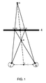
図1示すのは通常用スクリーン4におけるイメージを見る場合、3D立体視覚の現像原理及びスクリーン4に落込むかスクリーン4から飛び出すかの現像効果である。仮に瞳孔間距離(両眼間距離)は1とし、通常用スクリーン4は両眼と平行し、左目「L」と右目「R」が空間物点30を見る場合、左目のオフセット像点と右目のオフセット像点はそれぞれスクリーン平面4での31と32に位置し、両眼にある中間点2と空間物点30を結ぶ付け、スクリーン平面4での交差点は3である。3D立体視として、ひとつの状況は両眼が調節して、目をスクリーン平面4に合焦させ、両眼の輻輳が左目像点31と右目像点32を像点3に合わせ、脳が輻輳効果に慣れているので、左目オフセット像点31と右目オフセット像点32を自動的に空間像点30に反射する。スクリーン4での像点3に比べ、空間像点30が空間の奥行きを備え、3D立体視覚が誘発され、空間像点30がスクリーン4の後方に位置し、像点3がスクリーン平面4(交差視差)に落ち込むことに表徴され、もう一つ状況は、像点41が左目網膜(41=32)に落ち、且つ、像点42が右目網膜(42=31)に落ち、脳は二つの像点を自動的に空間イメージ40に合成する。スクリーン4での像点3に比べ、空間像点40が空間の奥行きがあるので、3D立体視覚を誘発して、空間像点40がスクリーン4の前に位置し、像点3がスクリーン平面4(非交差視差)から飛び出すことに表徴している。言い換えると、空間にある景物40を見る場合、スクリーン平面4での左目オフセット像点が41であり、右目オフセット像点が42であり、当該現像点はデフォーカス(発散)である。普通の3D立体番組を作成する場合、スクリーン平面4における右目フォーカスポイント32を左目の発散像点41とし、及び左目フォーカスポイント31を右目の発散像点42とし、その結果は視聴者脳の適応性が極端に欠如であるため、眩暈と吐き気を引き起こしてしまう。これを鑑み、3D立体表示にはこのような非交差視差という視聴モードを殆ど使用しない。
FIG. 1 shows the developing principle of 3D stereoscopic vision and the developing effect of falling into or out of the
通常、3D立体番組作成段階が前期作成段階と後期作成段階に分けている。前期作成段階において、二台撮影機により映画やテレビ番組を撮影し、後期作成段階において、撮影する番組を空間視差原理に応じてデータ化変換を行う。普通の場合、当該過程において、3D効果を強化するために、景物を多段階の被写界深度(通常は4〜8段階になる)に組み込むことに繋がる。後期作成段階では2D番組を3D立体番組に変換することもある。 Usually, the 3D 3D program creation phase is divided into the first phase and the second phase. In the first-generation stage, movies and television programs are photographed by two camera units, and in the second-stage generation stage, programs to be photographed are converted into data according to the spatial parallax principle. In the usual case, this process leads to incorporating the object into multiple levels of depth of field (usually 4 to 8 levels) in order to enhance the 3D effect. In the later creation stage, 2D programs may be converted into 3D stereoscopic programs.
通常の裸眼立体表示には幾多の技術難題が出て、良質な3D番組フィルムソースが不足となり、混信現象が存在するから、輝度と解像度を明らかに降下させ、過度な視差、過度なコンバージェンス或いは発散により、視聴者が疲れ目、頭痛、眩暈、吐き気などを引き起こす。これ以外に、発散とコンバージェンス間に頻繁に切り替えると、視聴者が番組を見る場合、畸形、歪みとゴースト感を生成させることに至る。 There are many technical challenges in normal autostereoscopic display, lack of good 3D programming film sources, and the presence of interference phenomena, so the luminance and resolution are obviously lowered, excessive parallax, excessive convergence or divergence This causes the viewer to have tired eyes, headaches, dizziness, nausea and so on. Besides this, frequent switching between divergence and convergence leads to the generation of template, distortion and ghosting when the viewer views the program.
本発明は発明特許である「調節可能な光学立体眼鏡」US14637439とWO2016140655技術原理を拡張するものである。 The invention extends the technical principle of the invention patent "Adjustable optical stereo glasses" US 14637439 and WO 2016 140 655.
本発明は前記の問題を解決し、裸眼で通常用スクリーンにおける2D番組を見る場合、3D立体感を形成する光学立体表示スクリーンを提供している。本発明は光学プリズム、球面と円筒レンズ、その他対称型レンズ、特殊光学素子(光学素子)より組成される光学組立部品を含み、その機能としては、光屈折の働きにより、視差を導入し、その内、(a)光学組立部品により通常用スクリーンにおける2D場面を見る場合、光学組立部品が左目が感知する左目のオフセット画像及び右目が感知するオフセット画像を誘発し、且つ、感知されるオフセット画像の空間位置とスクリーンでの2D場面の実際物理位置が異なり、(b)左目網膜における左目オフセット画像位置と右目網膜における右目オフセット画像位置間に空間差異を存在し(c)光学組立部品による触発する左目オフセット画像及び右目オフセット画像が交差視差超立体視モード、交差視差弱立体視モード、非交差視差超立体視モード、非交差視差弱立体視モード内の一つ視聴モードを形成し、これによって、視聴者に通常用スクリーンにおける2D場面を見る場合、3D立体視覚を感知させる。本発明の基本的な原理としては光屈折の働きにより視差を誘発することである。 The present invention solves the above problems and provides an optical stereoscopic display screen that forms a 3D stereoscopic effect when viewing a 2D program on a normal screen with the naked eye. The present invention includes an optical assembly composed of an optical prism, a spherical surface and a cylindrical lens, other symmetrical lenses, and a special optical element (optical element), and its function is to introduce parallax by the function of light refraction, (A) When viewing a 2D scene on a regular screen with an optical assembly, the optical assembly induces an offset image of the left eye sensed by the left eye and an offset image sensed by the right eye, and of the sensed offset image The spatial position and the actual physical position of the 2D scene on the screen are different, (b) there is a spatial difference between the left eye offset image position in the left eye retina and the right eye offset image position in the right eye retina (c) Offset image and right-eye offset image are cross parallax super stereo mode, cross parallax weak stereo mode, non-cross parallax super stereo Mode, one viewing mode nonintersecting parallax weak stereoscopic the mode formed, whereby, when viewing the 2D scene in the normal screen viewers to sense the 3D stereoscopic vision. The basic principle of the present invention is to induce parallax by the action of light refraction.
本発明は空間視差を利用し、視聴者に通常用スクリーンにおける2D番組を見る場合、3D立体視覚を誘発させ、本発明の光学立体スクリーンは光学組立部品により空間視差を提供している。前記の2D番組は任意の常用画像が可能で、通常の3D立体番組に処理する必要がない。通常用スクリーンにおける2D番組を見る場合、光学組立部品は視聴者の両眼のコンバージェンスを表示スクリーンから逸らして、両眼の合焦とコンバージェンスとは分離する目的を図り、引いてゼロ視差は3D立体視覚に対するマイナス効果を消す。当該技術手段はスクリーンとそのイメージプレーンを分離させ、両眼コンバージェンスと合焦を分離させ、視聴者の両眼は実際のスクリーンに合焦するが、イメージプレーンにコンバージェンスにする。視差は左目網膜と右目網膜において二つのオフセット画像を生成させ、脳はさらに二つのオフセット画像を融合して単一画像に処理してから3D立体感を誘発する。 The invention takes advantage of spatial parallax and induces viewers to view 3D stereoscopic images when viewing a 2D program on a regular screen, and the optical stereoscopic screen of the invention provides spatial parallax with an optical assembly. The above 2D program can be any commonly used image and does not need to be processed into a normal 3D stereoscopic program. When viewing a 2D program on a regular screen, the optical assembly diverts the convergence of the viewer's eyes from the display screen for the purpose of separating binocular focusing and convergence, with zero parallax being a 3D solid. Eliminate the negative effects on vision. The technique separates the screen and its image plane, separates binocular convergence and focusing, and allows the viewer's eyes to focus on the actual screen but converge on the image plane. The parallax causes two offset images to be generated in the left eye retina and the right eye retina, and the brain further fuses the two offset images and processes them into a single image before inducing 3D stereoscopic effect.
本発明の光学3D立体表示スクリーンは全面的に(a)通常用スクリーンにおける2D番組を見る場合、3D立体視覚を誘発すること(b)ディオプター無しこと;(c)顕著な発散なしこと;(d)輝度、明るさと透明度を増加すること;(e)解像度の損失が無いこと;(f)連続に延伸する空間の奥行きのこと;(g)連続的なイメージのあること;(h)歪みとゴースト現象無しを実現する。商業用途の場合、高透明度、高屈折率のある固体光学材料の光学素子を選択する。 The optical 3D stereoscopic display screen of the present invention induces 3D stereoscopic vision entirely (a) when viewing a 2D program on a conventional screen (b) no diopter; (c) no noticeable divergence; (d) 2.) increasing brightness, brightness and transparency; (e) no loss of resolution; (f) depth of continuously stretching space; (g) presence of continuous image; (h) distortion and Achieve no ghosting phenomenon. For commercial applications, optical elements of solid optical materials with high transparency, high refractive index are selected.
下記の例示的な実施例、詳しい記述、権利請求項及びアイコンを閲覧すると、本発明の特徴と技術革新に対し、より顕著になるであろう。下記には簡単な説明である。
図1は裸眼で通常用スクリーンを見ると、3D立体視覚を生じた現像原理を説明する。
図2は本発明の光学立体スクリーンの光学組立部品が幾多の光学素子より構成されることを説明している。
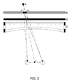
図3は本発明の光学立体表示組立部品における一つ実施例である上部断面図と裸眼で通常用スクリーンを見る場合、生じた3D立体感知効果を説明している。
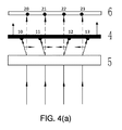
図4(a)は交差視差超立体視モードである。
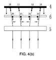
図4(b)は非交差視差超立体視モードである。
図4(c)は交差視差弱立体視モードである。
図4(d)は非交差視差弱立体視モードである。
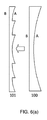
図5は三角プリズムがフレネルプリズムという同じ大きさの頂角を備え、連続的に繰り返す三角プリズムに取り替えられることを説明している。
図6(a)は等しい曲率の同心円平凹レンズが平凹レンズを取り替えることができ、または、等しい曲率の同心円平凹円筒レンズは平凹円筒レンズを取り替えることができることを説明している。
図6(b)はフレネルプリズムという等しい曲率の同心円平凸レンズが平凸レンズを取り替えることができ、またはフレネル円筒レンズで等しい曲率のある同心円平凸円筒レンズが平凸円筒レンズを取り換えることができると説明している。
図6(c)は垂直軸線に対し、具体的な角度を予め設定される一対長方形プリズムが円筒面平凹レンズに置き換わられ、具体的な規則により当該角度と曲率は相関関係を結びつけることを説明している。
図6(d)は垂直軸線に対し、具体的な角度を予め設定される一対長方形プリズムがフラットレンズに置き換わられ、具体的な規則により当該角度と曲率は相関関係を結びつけることを説明している。
図7(a)は図面のように、中心角のある三角プリズムが等しい頂角を備える中心角フレネルプリズムに置き換わられ、引いて平凹円筒レンズに置き換わられ、具体的な規則により頂角と曲率は相関関係を結びつけ、また、等しい曲率を備えるフレネル平凹円筒レンズに置き換わられることを説明する。
図7(b)は中心辺三角プリズムが等しい頂角のある中心辺フレネルプリズムに置き換わられ、引いて平凸円筒レンズに置き換わられ、具体的な規則により頂角と曲率は相関関係を結びつけ、また、等しい曲率を備えるフレネル平凸円筒レンズに置き換わられることを説明している。
図8は三角プリズムによりスクリーンにおける景物を見るモードを示している。
図9は二個の反転三角プリズムが異なる間隔空間により生じる水平変位差を示している。
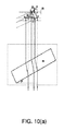
図10(a)は水平軸と反時計回りの夾角となる長方形プリズムにより空間景物を見る場合、水平変位が右向け及び垂直変位が後方向け現像を示している。
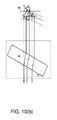
図10(b)は水平軸と時計回りの夾角となる長方形プリズムにより空間景物を見る場合、水平変位が左向け及び垂直変位が後方向け現像を示している。
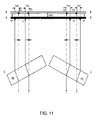
図11は一対の長方形プリズムにより通常用スクリーンを見る場合、形成する交差視差超立体視モードを示している。
図12はもう一つの一対長方形プリズムにより通常用スクリーンを見る場合、形成する交差視差弱立体視モードを示している。
図13は本発明における一つの実施例の光学立体表示組立部品により通常用スクリーンを見る場合、形成する交差視差超立体視モードを示し、その内凹面が視聴者向け曲面フラットレンズまたは円筒面フラットレンズを光学素子とすることを含む。
図14は本発明における一つの実施例である光学立体表示組立部品により通常用スクリーンを見る場合、形成する交差視差弱立体視モードを示し、その内一つの凸面が視聴者向け曲面フラットレンズまたは円筒面フラットレンズを光学素子とすることを含む。
図15は図8、図11におけるプリズムを組み合わせる光学組立部品により通常用スクリーンを見る場合、強化効果を備える交差視差超立体視モードを示している。
図16は本発明における一つの実施例である光学立体表示組立部品により通常用スクリーンを見る場合、形成する交差視差超立体視モードを示し、その内中心頂角三角プリズムと図6(c)、図15の変化による曲面レンズを組合わせる。
図17は本発明における一つの実施例である光学立体表示組立部品により通常用スクリーンを見る場合、形成する交差視差超立体視モードを示し、その内に中心頂角フレネルプリズムと図7(a)、図16の変化による曲面レンズを組合わせる。
図18は本発明における一つの実施例の光学立体表示組立部品により通常用スクリーンを見る場合、形成する交差視差超立体視モードを示し、その内に図7(a)、図17の変化による平凹レンズと曲面レンズまたは平凹円筒レンズと円筒レンズを組合わせる。
図19は本発明における一つの実施例である光学立体表示組立部品により通常用スクリーンを見る場合、形成する交差視差超立体視モードを示し、その内に図7(a)、図18の変化による同心円平凹レンズと曲面レンズまたは同心円円筒面平凹レンズと円筒レンズを組合わせる。
図20は図8、図12におけるプリズムを組合わせる光学組立部品により通常用スクリーンを見る場合、強化効果を備える交差視差弱立体視モードを示している。
図21は本発明における一つの実施例である光学立体表示組立部品により通常用スクリーンを見る場合、形成する交差視差弱立体視モードを示し、その内に中心辺三角プリズム及び図6(d)、図20の変化による曲面レンズを組合わせる。
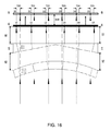
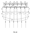
図22は本発明における一つの実施例である光学立体表示組立部品により通常用スクリーンを見る場合、形成する交差視差弱立体視モードを示し、その内に中心辺の対称フレネルプリズム及び図7(b)、図21の変化による曲面レンズを組合わせる。
図23は本発明における一つの実施例である光学立体表示組立部品により通常用スクリーンを見る場合、形成する交差視差弱立体視モードを示し、その内に図7(b)、図22の変化による平凸レンズと曲面レンズまたは平凸円筒レンズと円筒レンズを組合わせる。
図24は本発明における一つの実施例である光学立体表示組立部品により通常用スクリーンを見る場合、形成する交差視差弱立体視モードを示し、その内に図7(b)、図23の変化による平凸フレネルプリズムと曲面レンズまたはフレネル平凸円筒レンズと円筒レンズを組合わせる。
図25は同心円平凹レンズの三次元構図である。
図26は同心円平凸レンズの三次元構図である。
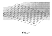
図27は同心円平凹円筒レンズの三次元構図である。
図28は同心円平凸円筒レンズ、平面フレネル円筒レンズともいう三次元構図である。
図29は本発明における光学立体表示組立部品の大寸法スクリーンを組合わせる方式を説明し、これは二次元方向に沿う幾多小寸法光学立体表示組立部品より構成されるものである。
A review of the following exemplary embodiments, detailed description, claims and icons will make the features and innovations of the present invention more noticeable. Below is a brief explanation.
FIG. 1 illustrates the development principle that resulted in 3D stereoscopic vision when viewing the normal screen with the naked eye.
FIG. 2 illustrates that the optical assembly of the optical three-dimensional screen of the present invention is comprised of a number of optical elements.
FIG. 3 illustrates the resulting 3D stereoscopic sensing effect when viewing the conventional screen with a naked eye and a top sectional view which is one embodiment of the optical stereoscopic display assembly of the present invention.
FIG. 4A is a cross parallax superstereoscopic mode.
FIG. 4 (b) is a non-crossing parallax hyperstereoscopic mode.
FIG. 4C is a cross parallax weak stereoscopic mode.
FIG. 4D shows the non-crossing parallax weak stereoscopic mode.
FIG. 5 illustrates that the triangular prism is replaced by a continuously repeating triangular prism with an apex angle of the same size as the Fresnel prism.
FIG. 6 (a) illustrates that concentric plano-concave lenses of equal curvature can replace plano-concave lenses, or concentric plano-concave cylindrical lenses of equal curvature can replace plano-concave cylindrical lenses.
In FIG. 6 (b), it is explained that concentric plano-convex lenses of equal curvature such as Fresnel prism can replace plano-convex lenses, or that concentric plano-convex cylindrical lenses having equal curvature can replace plano-convex cylindrical lenses by Fresnel cylindrical lenses. doing.
FIG. 6 (c) illustrates that a pair of rectangular prisms whose specific angles are preset with respect to the vertical axis are replaced with cylindrical plane-concave lenses, and that the angles and curvatures are correlated by specific rules. doing.
FIG. 6 (d) illustrates that a pair of rectangular prisms whose specific angles are preset with respect to the vertical axis are replaced with flat lenses, and that the angles and curvatures are correlated by specific rules. There is.
As shown in FIG. 7A, triangular prisms with central angles are replaced with central angle Fresnel prisms with equal apex angles, and are drawn and replaced with plano-concave cylindrical lenses. And curvature couple the correlation and explain that it can be replaced by a Fresnel plano-concave cylindrical lens with equal curvature.
FIG. 7 (b) shows that the central side triangular prism is replaced by the central side Fresnel prism with the equal apex angle, and is drawn and replaced with the plano-convex cylindrical lens, and the apex angle and the curvature link the correlation according to the specific rule. It also describes that it can be replaced by a Fresnel plano-convex cylindrical lens with equal curvature.
FIG. 8 shows a mode for viewing an object on a screen by a triangular prism.
FIG. 9 shows the horizontal displacement differences caused by the two inverted triangular prisms due to different spacings.
FIG. 10A shows development in the case where the space displacement is viewed from the horizontal axis in a counterclockwise direction, and the horizontal displacement is directed to the right and the vertical displacement is directed to the rear when the space object is viewed.
FIG. 10 (b) shows the development in the case where the horizontal displacement is directed to the left and the vertical displacement is directed to the rear when the space object is viewed by the rectangular prism which forms a clockwise angle with the horizontal axis.
FIG. 11 shows a cross parallax superstereoscopic mode formed when viewing a normal screen with a pair of rectangular prisms.
FIG. 12 shows the cross parallax low stereoscopic mode which is formed when viewing the normal screen by another pair of rectangular prisms.
FIG. 13 shows the cross parallax superstereoscopic mode formed when viewing the screen for ordinary use by the optical stereoscopic display assembly according to one embodiment of the present invention, and the concave surface thereof is a curved flat lens or a cylindrical flat lens for viewers As an optical element.
FIG. 14 shows the cross parallax weak stereoscopic mode formed when viewing a screen for ordinary use by the optical stereoscopic display assembly according to one embodiment of the present invention, and one convex surface of the mode is a curved flat lens for viewers or a cylinder Including the surface flat lens as an optical element.
FIG. 15 shows a cross parallax hyperstereoscopic mode with enhanced effect when viewing the screen for normal use with the optical assembly combining the prisms in FIGS.
FIG. 16 shows a cross parallax superstereoscopic mode formed when viewing a screen for ordinary use by the optical stereoscopic display assembly according to one embodiment of the present invention, of which a central apex angle triangular prism and FIG. 6 (c), Combine the curved lens according to the change in FIG.
FIG. 17 shows a cross parallax superstereoscopic mode formed when viewing a screen for ordinary use by an optical stereoscopic display assembly according to one embodiment of the present invention, in which a central apex angle Fresnel prism and FIG. 7 (a) are shown. , Combine the curved lens according to the change in FIG.
FIG. 18 shows a cross parallax superstereoscopic mode formed when viewing a screen for ordinary use by the optical stereoscopic display assembly according to one embodiment of the present invention, in which a plan according to the change of FIG. 7A and FIG. Combine concave and curved lenses or plano-concave cylindrical and cylindrical lenses.
FIG. 19 shows a cross parallax superstereoscopic mode formed when viewing a screen for ordinary use by the optical stereoscopic display assembly according to one embodiment of the present invention, in which a change in FIG. 7A and FIG. Combine a concentric plano-concave lens with a curved lens or a concentric cylindrical plano-concave lens with a cylindrical lens.
FIG. 20 shows a cross parallax weak stereoscopic mode with enhanced effect when viewing the normal screen with the optical assembly combining the prisms in FIGS.
FIG. 21 shows a cross parallax weak stereoscopic mode formed when viewing a screen for ordinary use by the optical stereoscopic display assembly according to one embodiment of the present invention, in which a center side triangular prism and FIG. 6 (d), The curved lens according to the change of FIG. 20 is combined.
FIG. 22 shows a cross-parallax weak stereoscopic mode formed when viewing a screen for ordinary use by an optical stereoscopic display assembly according to an embodiment of the present invention, in which a symmetric Fresnel prism of the central side and FIG. 21), the curved lens according to the change of FIG. 21 is combined.
FIG. 23 shows the cross parallax weak stereoscopic mode formed when viewing the screen for ordinary use by the optical stereoscopic display assembly according to one embodiment of the present invention, in which a change in FIG. 7 (b) and FIG. Combine a plano-convex lens with a curved lens or a plano-convex cylindrical lens with a cylindrical lens.
FIG. 24 shows a cross parallax weak stereoscopic mode formed when viewing a screen for ordinary use by the optical stereoscopic display assembly according to one embodiment of the present invention, in which a change in FIG. 7 (b) and FIG. Combine a plano-convex Fresnel prism with a curved lens or a Fresnel plano-convex cylindrical lens with a cylindrical lens.
FIG. 25 shows a three-dimensional composition of a concentric plano-concave lens.
FIG. 26 shows a three-dimensional composition of a concentric plano-convex lens.
FIG. 27 shows a three-dimensional composition of a concentric plano-concave cylindrical lens.
FIG. 28 shows a three-dimensional composition called a concentric plano-convex cylindrical lens or a flat Fresnel cylindrical lens.
FIG. 29 illustrates the method of combining the large size screens of the optical stereoscopic display assembly in the present invention, which is comprised of multiple small size optical stereoscopic display assemblies along a two-dimensional direction.
図2は本発明における光学立体表示組立部品5の光学組立部品の概略図である。組立部品における光学素子ごとに、それぞれ100、200、300…などで表示する。商業用途とニーズに基づき、光学組立部品における光学素子数は1ないし100間にしても構わない。
FIG. 2 is a schematic view of the optical assembly of the optical
図3は本発明における一つの実施例である光学立体表示組立部品5の上部断面図であり、左目Lと右目Rにより通常用スクリーン4における景点3を見る場合、3D立体視覚を形成する現像原理を説明している。仮に瞳孔間距離を1とし、スクリーン4が両眼と平行し、図19のように、スクリーン4における景点3を見る場合、光学素子の屈折のため、スクリーン4の像スクリーン6が後方への変位を発生し、像スクリーン6における右目オフセット画像と左目オフセット画像が相応に31と32に位置し、立体視から言うと、両眼は調節することによりスクリーン4に焦点を合わさせ、脳は両眼のコンバージェンス効果に慣れたので、左目オフセット像点31と右目オフセット像点32を自動的に組合わせてから空間景物30に反射する。よって、観賞空間において、視聴者の両眼は景物30にコンバージェンスにし、これにより、3D立体感知を誘発し、像スクリーン6がスクリーン4の後方に落ち、代表的な景物3がスクリーン4に落込み、交差視差視聴モードを形成する。
FIG. 3 is a top cross-sectional view of an optical
図4(a)−4(d)は本発明における光学立体表示スクリーンの四種立体視モードである。本発明における光学立体表示組立部品5により通常用スクリーン4における2D番組を見る場合、表示スクリーン4における左側景点10、11及び右側景点12、13がそれぞれ像スクリーン6における左側像点20、21及び右側像点22、23に落ち、空間変位を生じるから、両眼をコンバージェンスにさせ、観賞方向に沿い、表示スクリーン4から移し、両眼の合焦と両眼のコンバージェンスを分離することを形成する。両眼の瞳孔間距離は左目網膜に現像する画像と右目網膜に現像する画像間に微小な差異を生じさせ、脳が左目網膜と右目網膜における二枚の視差画像を組合せて融合する要求を満足し、脳が空間の奥行きを回復することを誘発し、立体視覚感知を生じる。なお、3D現像特徴により、像スクリーン6が表示スクリーン4の後方(または後方向けの方向)に位置し、図4(a)は縮小現像の交差視差超立体視モードを表し、像スクリーン6が表示スクリーン4の前方(或いは前向けの方向)に位置し、図4(b)は縮小現像の非交差視差超立体視モードを表し、像スクリーン6が表示スクリーン4の後方(或るいは後向けの方向)に位置し、図4(c)は拡大現像の交差視差弱立体視モードを表し、像スクリーン6が表示スクリーン4の前方(或いは前向けの方向)に位置し、図4(d)は拡大現像の非交差視差弱立体視モードを表す。
FIGS. 4 (a) -4 (d) show four types of stereoscopic viewing modes of the optical stereoscopic display screen in the present invention. When viewing a 2D program on the
図4(a)は本発明が水平視差と垂直視差の交差視差超立体視モードに繋がることを示す。当該モードにおいて、像スクリーン6が表示スクリーン4の後方(或いは後向けの方向)に位置する。なお、スクリーン4の中心点を参照とし、本発明における光学立体表示組立部品5によりスクリーン4の左側景点10、11を見る場合、像スクリーン6における像点20、21のように、右への水平変位を生じ、本発明における光学立体表示組立部品5によりスクリーン4の右側景点12、13を見る場合、像スクリーン6における像点22、23のように、左方向への水平変位を生じ、垂直変位が後方向けで、縮小現像を形成し、交差視差超立体視モードである。特に記載がない限り、垂直方向は下記の記載において目で見る視線方向を表示する。
FIG. 4 (a) shows that the present invention leads to a cross parallax superstereoscopic mode of horizontal parallax and vertical parallax. In this mode, the
図4(b)は本発明が水平視差と垂直視差との非交差視差超立体視モードに関することを示す。当該モードにおいて、像スクリーン6が表示スクリーン4の前方(或いは前向けの方向)に位置する。なお、スクリーン4の中心点を参照とし、本発明における光学立体表示組立部品5により、スクリーン4の左側景点10、11を見る場合、像スクリーン6における像点20、21のように、右方向への水平変位を生じ、本発明における光学立体表示組立部品5により、スクリーン4における右側景点12、13を見る場合、像スクリーン6における像点22、23のように、左方向への水平変位を生じ、垂直変位が前向け、縮小現像を生成し、非交差視差超立体視モードである。
FIG. 4 (b) shows that the invention relates to a non-crossing parallax superstereoscopic mode of horizontal parallax and vertical parallax. In this mode, the
図4(c)は本発明が水平視差と垂直視差との交差視差弱立体視モードに繋がることを示す。当該モードにおいて、像スクリーン6が表示スクリーン4の後方(或いは後向けの方向)に位置する。なお、スクリーン4の中心点を参照とし、本発明における光学立体表示組立部品5により、スクリーン4の左側景点10、11を見る場合、像スクリーン6における像点20、21のように、左方向への水平変位を生じ、本発明における光学立体表示組立部品5により、スクリーン4の右側景点12、13を見る場合、像スクリーン6における像点22、23のように、右方向への水平変位を生じ、垂直変位が後向け、拡大現像を生成し、交差視差弱立体視モードである。
FIG. 4 (c) shows that the present invention leads to a cross parallax weak stereoscopic mode of horizontal parallax and vertical parallax. In this mode, the
図4(d)は本発明が水平視差と垂直視差との非交差視差弱立体視モードに繋がることを示す。当該モードにおいて、像スクリーン6が表示スクリーン4の前方(或いは前向けの方向)に位置する。なお、スクリーン4の中心点を参照とし、本発明の光学立体表示組立部品5により、スクリーン4の左側景点10、11を見る場合、像スクリーン6における像点20、21のように、左方向への水平変位を生じ、本発明の光学立体表示組立部品5により、スクリーン4の右側景点12、13を見る場合、像スクリーン6における像点22、23のように、右方向への水平変位を生じ、垂直変位が前向け、拡大現像を生成し、非交差視差弱立体視モードである。
FIG. 4D shows that the present invention leads to a non-crossing parallax weak stereoscopic mode of horizontal parallax and vertical parallax. In this mode, the
図5は同じ頂角でフレネルプリズムという連続で繰り返す三角プリズム101により光学三角プリズム100を置き換わることができ、屈折の基本的な原理に基づき、三角プリズムが同じ頂角を保持すれば、入射する平行光線が二個のメイン光学平面を介してから、屈折して射出する光線が同じ方向を保持することを説明している。
In FIG. 5, the optical
図6(a)は同心円平凹レンズ101により平凹レンズ100を置き換わることができ、屈折の基本的な原理に基づき、相応な表面位置で一致の曲率を保持すれば、屈折して射出する光線が同じ方向を保持することを説明する。また、フレネル平凹円筒レンズ101により平凹円筒レンズ100を置き換わることができる上、前記と近似的な効果を生じることができることを説明している。
In FIG. 6A, the plano-
図6(b)はフレネルプリズムという同心円平凸レンズ101で平凸レンズ100を置き換わることができ、屈折の基本的な原理に基づき、相応な表面位置で一致の曲率を保持すれば、屈折して射出する光線が同じ方向を保持することを説明する。また、フレネル円筒レンズという平凸円柱レンズ101で平凸円筒レンズ100を置き換わることができる上、前記と近似的な効果を生じることができることを説明する。
In FIG. 6 (b), the plano-
図6(c)は円筒面フラットレンズ101で垂直方向と事前に設定角度となる一対の長方形プリズム100を置き換わることができることを説明する。仮に、光学素子101は無限の連続的小長方形プリズムペアにより結合されるものであれば、頂角と曲率が具体的な規則に応じ、関連関係を形成し、例えば、頂角と曲率角は等しいことに近似する上、相対に小さく、長さも相対に長い、...等等、それで、入射する平行光線が光学面AとBを通過して、屈折を経てから射出する光線が同じ方向を保持する。
FIG. 6C illustrates that the cylindrical
図6(d)は円筒面フラットレンズ101で一対の垂直方向と事前に設定角となる長方形プリズム100を置き換わることができると説明さする。仮に、光学素子101は無限の連続で小長方形プリズムペアにより結合されるものであれば、頂角と曲率が具体的な規則に応じ、関連関係を形成し、例えば、頂角と曲率角は等しいことに近似する上、相対に小さく、長さが相対に長い、...等等、それで、入射する平行光線が光学面AとBを通過して、屈折を経てから射出する光線が同じ方向を保持する。
FIG. 6D explains that the cylindrical
図7(a)は中心角フレネルプリズム101で中心角三角プリズム100を置き換わることができ、引いて平凹円筒レンズ102に置き換えられ、再度、フレネル平凹円筒レンズ103に置き換えることを説明する。屈折の基本的な原理に基づき、相応な表面位置における曲率と頂角が同じければ、且つ、頂角と曲率が具体的な規則に応じて関連関係を形成すれば、例えば頂角と曲率が等しいことに近似する上、相対に小さく、長さが相対に長い、...等等、それで、入射する平行光線が光学面AとBを通過して、屈折を経てから射出する光線が同じ方向を保持する。
FIG. 7A illustrates that the central angle
図7(b)は中心辺フレネルプリズム101で中心辺三角プリズム100を置き換わることができ、引いて平凸円筒レンズ102に置き換わられ、再度フレネル平凸円筒レンズ103に置き換わられることができることを説明する。屈折の基本的な原理に基づき、相応な表面位置における曲率と頂角が同じければ、且つ、頂角と曲率が具体的な規則に応じて関連関係を生成すれば、例えば、頂角と曲率角は等しいことに近似する上相対に小さく、長さが相対に長い...等等であれば、入射する平行光線が光学面AとBを通過して、屈折を経てから射出する光線が同じ方向を保持する。
In FIG. 7B, the central
両眼の視差と空間視差は3D立体視覚を感知する最も重要な因子である。本発明は光学組立部品より構成された光学立体スクリーンを提供し、通常用スクリーンにおける2D番組を見る場合、3D立体視覚を感知させ、視聴者の脳を誘発して奥行き感を生じさせ、連続的に延伸する空間を回復させ、3D立体視覚と連続的な被写界深度を生じさせる。本発明の光学立体スクリーンは空間の多層深度の技術問題を解決するのみならず、3D立体視用3D立体番組の作製が要らなくなる。 Binocular disparity and spatial disparity are the most important factors in sensing 3D stereoscopic vision. The present invention provides an optical three-dimensional screen composed of an optical assembly, and when viewing a 2D program on a general purpose screen, it senses 3D three-dimensional vision, induces the viewer's brain to create a sense of depth, and continuous. It restores the space extending to create 3D stereovision and continuous depth of field. The optical three-dimensional screen of the present invention not only solves the technical problem of multi-layered depth of space, but also does not require the creation of a 3D stereoscopic program for 3D stereoscopic viewing.
商業用立体スクリーンは人々がコンバージェンスの調節及び視差を適応するため存在する差異を考えべき、超限度コンバージェンスと発散の生成を防ぎ、広汎なニーズに対応すべき、快適性、便利性と調節可能性を最大限に向上させる。正確に設計する光学立体スクリーンは交差視差、コンバージェンス現像、適当な空間奥行きと強烈な3D視覚感という特徴を備えべく。図4(a)、4(b)、4(c)、4(d)において、図4(a)は交差視差超立体視モードが代表され、適当な空間奥行き感と強烈な立体視覚感を有し、3D立体表示について言えば、当該立体表示は最優先の立体視モードであり;図4(b)は非交差視差超立体視モードが代表され、近接の景物を適当的に制限せず、極度の視覚コンバージェンスとなり、過度の内斜視に至り、視覚疲労と視覚病気を引き起こす。なお、視聴者の脳は十分に近接現像に適応することができず、特にデフォーカスのイメージである。よって、これは商業化製品として開発するのは不適合であり、図4(c)は交差視差弱立体視モードを代表し、遠距離景物を適当に制限せずと、極度の視覚発散を形成し、過度の外斜視になる。なお、当該視聴モードは3D視覚が適当に感知されるが、空間の奥行き感がよくない。もし、映画制作の際に屈折をコントロールする上、近接場面を制限すれば、当該立体表示は次の最優先の立体視モードであり、図4(d)は非交差視差弱立体視モードを代表し、近接と遠距離の景物を制限せずと、極度の収束と発散型視覚を形成し、過度的な内または外向けの斜視に至り、視覚疲労と視覚病気を引き起こす。なお、視聴者の脳は遠距離景物の拡大現像に慣れず、特にデフォーカスのイメージである。よって、これは商業化製品としての開発には不適合である。前記を鑑み、結論としては交差視差により3D立体視覚を感知させることは最良な選択であり、なお、超立体は弱立体より優先的な視聴モードである。 Commercial stereoscreens should consider the differences that people have in order to adapt convergence adjustment and parallax, prevent over-convergence and divergence generation, and meet a wide range of needs, comfort, convenience and adjustability Improve the best. The correctly designed optical stereo screen should be characterized by cross parallax, convergence development, adequate spatial depth and intense 3D visual sensation. In FIGS. 4 (a), 4 (b), 4 (c) and 4 (d), the cross parallax superstereoscopic mode is represented in FIG. 4 (a), and an appropriate sense of spatial depth and a strong sense of stereoscopic vision are obtained. In the case of 3D stereoscopic display, the stereoscopic display is the highest priority stereoscopic mode; FIG. 4 (b) is represented by the non-crossed parallax superstereoscopic mode and does not appropriately limit nearby objects. It causes extreme visual convergence, leads to excessive esotropia, and causes visual fatigue and visual ailments. In addition, the viewer's brain can not be sufficiently adapted to proximity development, and in particular is an image of defocus. Thus, it is unsuitable for development as a commercialized product, and FIG. 4 (c) represents the cross parallax weak stereoscopic mode, and forms extreme visual divergence without appropriately limiting the distance object. , Become excessive exotropia. In addition, although the said viewing-and-listening mode is 3D vision being sensed appropriately, the feeling of depth of space is not good. If refraction is controlled during movie production, and the proximity scene is limited, the stereoscopic display is the next highest priority stereoscopic mode, and FIG. 4 (d) represents the non-crossing parallax weak stereoscopic mode. Not limiting the proximity and distance objects, it forms extreme convergence and diverging vision, leading to excessive inward or outward oblique vision, causing visual fatigue and visual disease. It should be noted that the viewer's brain is not accustomed to extended development of distant objects, and in particular is a defocused image. Thus, this is not suitable for development as a commercialized product. In light of the foregoing, it is concluded that 3D stereoscopic vision is perceived as the best for cross-parallax, and super-stereo is a more preferred viewing mode than weak stereo.
本発明の光学立体表示組立部品5は光学素子より組成されたものである。図2のように、各々の素子は光学プリズム、球面と円筒レンズ、関連のフレネルプリズム、その他対称レンズ、特殊光学素子等を代表する。光学立体表示組立部品5により、通常用スクリーン幕4における2D番組を見る場合、屈折がイメージプレーン6に空間変位を生成させ、両眼をコンバージェンスにし、視線方向に沿わせて、スクリーン4から移してから、両眼のコンバージェンスと合焦の分離を生成させる。従って、ゼロ視差が3D立体視覚に対するマイナス効果を消し、立体感を誘発する上、図4(a)−4(d)のような3D立体視モードを実現する。商業用途に対し、光学立体表示組立部品5の厚みができる限り薄くすることが好ましく、これを高屈折率のある光学材料を選択することにより実現することができる。それで、光学素子を設計する場合、図5のようなフレネルプリズム結構は三角プリズムより優れ、図6(a)に示すフレネル同心円形平凹レンズとフレネル平凹円筒レンズは平凹レンズと平凹円筒レンズより優れ、図6(b)に示すフレネル同心円平凸レンズとフレネル平凸円筒レンズは平凸レンズと平凸円筒レンズより優れる。なお、本発明における光学立体表示組立部品により、通常用スクリーンにおける2D番組を見る場合、立体視覚を感知する以外に、また、直接に観賞する場合より更なる鮮やかな色及びより明るく、より明瞭なイメージが得られる。これは背景光と迷光が目に及ぼす直接影響は光学素子のろ過を経てから影響より遥かに大きいからである。本発明における光学立体表示組立部品は分離及び背景光線と迷光のろ過機能を有する幾多の光学素子より構成するものである。
The optical
図8のように、光学素子100は水平軸線に沿い頂角70である三角プリズムを置くものである。光学素子100を介し、通常用スクリーン4における三つの物点10、11、12を見る場合、屈折は視線に空間で偏向を生成させ、イメージプレーン6における像点20、21、22のように、水平変位が左向け、垂直変位が後向けになった。三角プリズム100は空間変位を実現することが三角プリズムを立体表示組立部品5の光学素子とすることができ、図4(a)−4(d)のような視聴モードの機能要求を実現することを説明する。別に記載がない限り、三角プリズムは本文には二つのメイン光学平面またはその延伸が一つの頂角に交差すると定義される。
As shown in FIG. 8, the
図9のように、左側部分は頂角70である三角プリズム100と頂角71である三角プリズム101を96間隔で相対に置き、右側部分は頂角70である三角プリズム100と頂角71である三角プリズム101を97間隔で相対に置く。左側部分と右側部分との区別としては、97の間隔空間が96より大きい。光学素子100と101を介して、物点10、11及び12、13を見る場合、屈折が視線に空間で偏向を生成させ、まさに、相応な像点20、21及び22、23のように、生成する空間変位は水平変位(720,721)と(722,723)が左向け及び垂直変位がゼロである。図9の左側部分と右側部分を比べると、間隔空間97が96より大きくければ、大きくほど、水平変位(722、723)が(720、721)より大きくなる。従って、間隔空間を調整することにより、水平変位(即ち、水平視差)を調節することを実現することができる。
As shown in FIG. 9, the left part has the
図10(a)、10(b)のように、長方形プリズム100と水平軸は反時計回りの角度60と時計回り角度61の事前に設定する角度となるように放置する。光学素子100を介して、物点10、11、12を見る場合、屈折が視線に空間で偏向を生成させ、像点20、21、22のように、空間変位は水平変位720と垂直変位820を含む。事前に設定する反時計回り角度60長方形プリズムの水平変位が右向け、垂直変位が後向け、事前に設定する時計回り角度61長方形プリズムの水平変位が左向け、垂直変位が後向けとなる。事前に設定する角度の長方形プリズム100が空間変位の実現は長方形プリズムを立体表示組立部品5の光学素子とすることが可能で、如図4(a)−4(d)のような視聴モードの機能要求を実現することを説明する。別な記載がないことに限り、本文には長方形プリズムを二つのメイン光学平面が相互に並行すると定義する。
As shown in FIGS. 10 (a) and 10 (b), the
図11のように、一対の長方形プリズム100と110と水平軸線間において、その一つは事前に設定する反時計回り角度で、もう一つは事前に設定する時計回り角度である。基本的な光学理論により、それを介して、通常用スクリーン4における2D番組を見る場合、下記の状況が発生する。光学素子無しでスクリーン4における2D番組を見る場合、視聴者がスクリーン4に直接合焦して、コンバージェンスにし、スクリーン4における物体及びその対応の現像がそのままで不変で、空間変位も発生せず、ゼロ視差となり、立体感無しである。長方形プリズムを介して、スクリーン4における2D番組を見る場合、スクリーン4における左側物点10、11が右方向への水平変位(720、721)が発生され、像スクリーン6における像点20、21のように、スクリーン4における右側物点12、13が左方向への水平変位(722、723)が発生され、イメージスクリーン6における現像点22と23のように、当該長方形プリズム結構は縮小イメージを生み出し、像スクリーン6がスクリーン4の後方(或いは後向けの方向)に位置するから、後向けの垂直変位820が発生することに至る。垂直変位が発生する結果としては、両眼をコンバージェンスにし、視線方向に沿って表示スクリーン4と離れ、両眼の合焦と両眼のコンバージェンスを分離することを形成する。両眼間距離は左右網膜における二つの現像間に微小な差異を存在させ、脳により空間視差を組合せて融合する要求を満たす上、3D立体感知を誘発する。
As shown in FIG. 11, between the pair of
図12のように、一対の長方形プリズム100と110と水平軸線において、その一つは事前に設定する反時計回りの角度で、もう一つは事前に設定する時計回りの角度である。図11と比較すると、この光学素子結構は水平変位(720,721)と(722,723)様な拡大イメージを生成し、当該長方形プリズム結構は拡大イメージを生成する。像スクリーン6が表示スクリーン4の後方(或いは後向けの方向)に位置するから、後向けの垂直変位820となる。垂直変位を発生する結果としては、両眼をコンバージェンスにし、視線方向に沿って、表示スクリーン4を離れ、両眼の合焦と両眼のコンバージェンスを分離することを形成する。両眼間距離は左右網膜における二つの現像間に微小な差異を存在させ、脳による空間視差を組合せて融合する要求を満たす上、3D立体感知を誘発する。
As shown in FIG. 12, with respect to the pair of
図13のように、本実施例において、本発明における光学立体表示組立部品5の光学素子は凹フラットレンズ100または凹面円筒レンズ100であり、それを図11のような無限個の連続小長方形プリズムペア100と110を組合わせるとみなすことができ、光学立体表示組立部品5と表示スクリーン4間の間隔空間90と91は光学素子辺縁からスクリーン4までの測りである。一般的には、左、右間隔空間が等しいである(90=91)。本発明における表示組立部品5により、スクリーン4における2D番組を見る場合、スクリーン4の左側物点10、11、12は右向けの水平変位(720,721,722)が発生し、イメージプレーン6における現像点20、21、22のようであり、スクリーン4の右側物点13、14、15は左向けの水平変位(723,724,725)が発生し、イメージプレーン6における現像点22、23、24のようである。イメージプレーン6が表示スクリーン4の後方(或いは後向けの方向)に位置するから、後向けの垂直変位820に至る。イメージプレーン6は垂直変位の発生結果としては、ゼロ視差が3D立体感知に対するマイナス効果を削除し、視線方向に沿う両眼コンバージェンスがスクリーン4に遠ざかることにより、両眼の合焦と両眼のコンバージェンスを分離させる上、スクリーン4後方(或いは後向けの方向)に位置する縮小イメージを生成させる。
As shown in FIG. 13, in the present embodiment, the optical element of the optical
図14のように、本実施例において、本発明における光学立体表示組立部品5の光学素子は凸フラットレンズ100または凸面円筒レンズ100である。図13と比べると、この光学素子結構が水平変位(720,721,722が723,724,725に相対する)のような拡大イメージを生成させ、イメージプレーン6が表示スクリーン4の前方(或いは前向けの方向)に位置するので、前向けの垂直変位820に至る。イメージプレーン6に相対して、垂直変位を発生する直接結果としては、ゼロ視差が3D立体感知に対するマイナス効果をけし、視聴視線方向に沿い、両眼をコンバージェンスにし、表示スクリーン4に遠ざかり、両眼の合焦と両眼のコンバージェンスを分離させ、表示スクリーン4後方(或いは後向けの方向)に位置する拡大イメージを形成する。
As shown in FIG. 14, in the present embodiment, the optical element of the optical
図15のように、上部が一対の三角プリズム(102,112)、下部が一対の長方形プリズム(100,110)である光学素子により、通常用スクリーン4における2D番組を見る場合のモードは交差視差超立体視モードである。屈折は水平変位(720,721)を右向け、(722,723)を左向けにさせ、スクリーン4における物点10,11と12,13がイメージプレーン6における像点20,21と22,23に反映させ、イメージプレーン6がスクリーン4の後方(或いは後向けの方向)に位置し、後向けの垂直変位820となる。光学立体表示組立部品5と表示スクリーン4間の間隔空間が90と91であり、上部の光学素子と下部の光学素子間の間隔空間が92と93である。当該光学素子(100,110,102,112)結構が図8と図11のようなプリズムの組合わせ効果と見なすことができる。相加効果なので、強化型交差視差超立体視による視聴する場合のイメージを縮小する視覚体験を代表する。
As shown in FIG. 15, in the case of viewing a 2D program on the
図16のように、本実施例において、本発明の光学立体表示組立部品5は中心頂角対称三角プリズム100を上部光学素子とし、及び凹面が視聴者向けの凹円筒レンズ200を下部光学素子とすることを含む。本発明の光学立体表示組立部品5により、通常用スクリーン4における2D番組を見る場合、スクリーン4における左側物点10,11,12が右向けの水平変位(720,721,722)を生成し、イメージプレーン6における像点20,21,22で現像し、スクリーン4における右側物点13,14,15が左向けの水平変位(723,724,725)を生成し、イメージプレーンスクリーン6における像点22,23,24で現像し、イメージプレーン6がスクリーン4の後方(或いは後向けの方向)に位置し、後向けの垂直変位820となる。光学立体表示組立部品5と表示スクリーン4間の間隔空間が90と91であり、上部の光学素子と下部の光学素子間の間隔空間が92と93である。本発明の立体表示組立部品5結構は図15の変化によるものと見なされ、即ち、光学素子(102,112)を連接して延伸する上、図6(c)様な円筒面凹レンズ200により、光学素子(100,110)を置き換わる。イメージプレーン6が垂直変位820を発生する結果として、両眼をコンバージェンスにし、観賞視線方向に沿わせて、スクリーン4に遠ざかり、両眼の合焦と両眼のコンバージェンスとの分離を形成し、スクリーン4後方(或いは後向けの方向)に落ちる縮小イメージに表現する。
As shown in FIG. 16, in the present embodiment, the optical
図17のように、本実施例において、本発明の光学立体表示組立部品5が中心頂角対称フレネルプリズム100を上部の光学素子とし、及び凹面が視聴者向けの凹面円筒レンズ200を下部の光学素子とすることを含む。本発明の立体表示組立部品5結構が図16の変化によるものと見なし、即ち、中心頂角対称フレネルプリズム100により、図5に示す中心頂角対称三角プリズム100を置き換わる。図16と比べると、この光学素子結構は水平変位720,721,722,723より724,725に対する表徴が縮小イメージを生成させる。イメージプレーン6が発生する垂直変位結果として、両眼をコンバージェンスにし、観賞視線方向に沿わせ、スクリーン4に遠ざかり、両眼の合焦と両眼のコンバージェンスとの分離を形成し、スクリーン4後方(或いは後向けの方向)に落ちる縮小イメージに表現する。
As shown in FIG. 17, in the present embodiment, the optical
図18のように、本実施例において、本発明の光学立体表示組立部品5が平凹レンズ100または平凹円筒レンズ100を上部の光学素子とし、及び凹面が視聴者向けの凹フラットレンズ200または凹円筒レンズ200を下部の光学素子をとすることを含む。本発明の立体表示組立部品5結構が図17の変化によるものと見なし、即ち、図7(a)の様な平凹レンズまたは平凹円筒レンズ102により中心頂角フレネルプリズム101を置き換わる。図17と比べると、この光学素子結構も水平変位(720,721,722)より(723,724,725)に対する表徴が縮小イメージを生成する。イメージプレーン6が発生する垂直変位結果としては、両眼をコンバージェンスにし、観賞視線方向に沿わせ、スクリーン4に遠ざかり、両眼の合焦と両眼のコンバージェンスとの分離を形成させ、スクリーン4後方(或いは後向けの方向)に落ちる縮小イメージに表現される。
As shown in FIG. 18, in the present embodiment, the optical
図19のように、本実施例において、本発明の光学立体表示組立部品5が同心円平凹レンズ100またはフレネル平凹円筒レンズ100を上部の光学素子とし、及び凹面が視聴者向けの凹フラットレンズ200または凹円筒レンズ200を下部の光学素子とすることを含む。本発明の立体表示組立部品5結構を図18の変化によるものと見なし、即ち、図7(a)の様な同心円平凹レンズ或フレネル平凹円筒レンズ103により、平凹レンズまたは平凹円筒レンズ102を置き換わる。図18と比べ、この光学素子結構も水平変位(720,721,722)より(723,724,725)に相対する表徴が縮小イメージを生成する。イメージプレーン6が発生する垂直変位の結果として、両眼をコンバージェンスにし、観賞視線方向に沿わせ、スクリーン4に遠ざかり、両眼の合焦と両眼のコンバージェンスとの分離を形成させ、スクリーン4後方(或いは後向けの方向)に落ちる縮小イメージに表現する。
As shown in FIG. 19, in the present embodiment, the optical
図13、16、17、18、19の様な実施例について、本発明の光学立体表示組立部品5により、通常用スクリーン4における2D番組を見る場合、スクリーン4における左側物点10,11,12が右向けの水平変位(720,721,722)を生成し、イメージプレーン6における像点20,21,22のようであり、スクリーン4における右側物点13,14,15が左向けの水平変位(723,724,725)を生成し、イメージプレーン6における像点22,23,24のようであり、イメージプレーン6がスクリーン4の後方(或いは後向けの方向)に位置し、後方向けの垂直変位820を形成する。光学立体表示組立部品5と表示スクリーン4間の間隔空間が90と91であり、上部光学素子と下部光学素子間の間隔空間が92と93である。イメージプレーン6は垂直変位が発生するので、両眼の合焦と両眼のコンバージェンスを分離させる上、ゼロ視差によるマイナス効果を消し、3D立体感知を誘発する一方、縮小イメージを形成する。よって、これらの実施例は図4(a)のような交差視差超立体視モードに表現する。
When viewing a 2D program on the
図20のように、上部が一対の三角プリズム(102,112)と下部が一対長方形プリズム(100,110)である光学素子により通常用スクリーン幕4における2D番組を見る場合、交差視差弱立体視モードである。屈折は水平変位(720,721)に左向けを、(722,723)に右向けをさせ、表示スクリーン4における物点10,11と12,13がイメージプレーン6における像点20,21及22,23に反映させ、イメージプレーン6がスクリーン4の後方(或いは後向けの方向)に位置し、後方向けの垂直変位820を形成する。光学立体表示組立部品5と表示スクリーン4間の間隔空間が90と91であり、上部光学素子と下部光学素子間の間隔空間が92と93である。当該光学素子(100,110,102,112)結構を図8と図11のようなプリズムを組み合わせる効果と見なすことができる。相加効果のため、それは、強化型交差視差弱立体視拡大イメージの視覚体験が代表される。
As shown in FIG. 20, when viewing a 2D program in the
図21のように、本実施例において、本発明の光学立体表示組立部品5は中心辺対称三角プリズム100を上部光学素子とし、及び凸面が視聴者向けの凸円筒面フラットレンズ200を下部光学素子とすることを含む。本発明の光学立体表示組立部品5により、通常用スクリーン4における2D番組を見る場合、スクリーン4における左側物点10,11,12が左向けの水平変位(720,721,722)を生成し、イメージプレーン6における像点20,21,22に現像され、スクリーン4における右側の物点13、14、15が右向けの水平変位(723,724,725)を発生し、イメージプレーン6における像点22,23,24に現像され、イメージプレーン6がスクリーン4の後方(或いは後向けの方向)に位置し、後方向けの垂直変位820を形成する。光学立体表示組立部品5と表示スクリーン4間の間隔空間が90と91であり、上部光学素子と下部光学素子間の間隔空間が92と93である。本発明の立体表示組立部品5の結構を図20の変化によるものと見なすことができ、即ち、一対の三角プリズム102と112を連接して延伸することを通過し、また、図6(d)のように、101で一対長方形プリズム100を置き換わる。イメージプレーン6が発生する垂直変位820の結果として、両眼をコンバージェンスにし、観賞視線方向に沿わせてスクリーン4に遠ざかり、両眼の合焦と両眼のコンバージェンスとの分離を形成し、スクリーン4後方(或いは後向けの方向)に落ちる拡大イメージに表現する。
As shown in FIG. 21, in the present embodiment, the optical
図22のように、本実施例において、本発明の光学立体表示組立部品5は中心辺対称フレネルプリズム100を上部光学素子とし、及び凸面が視聴者向けの凸円筒レンズ200を下部光学素子とすることを含む。本発明の立体表示組立部品5結構を図21の変化によるものと見なすことができ、即ち、図7(b)の様な中心辺対称フレネルプリズム101により、中心辺対称三角プリズム100を置き換わる。図21と比べ、この光学素子結構は水平変位(720,721,722)より(723,724,725)に相対する表徴が拡大イメージを生成することに表現する。イメージプレーン6が発生する垂直変位820の結果として、両眼をコンバージェンスにし、観賞視線方向に沿わせてスクリーン4に遠ざかり、両眼の合焦と両眼のコンバージェンスとの分離を形成し、スクリーン4後方(或いは後向けの方向)に落ちる拡大イメージに表現する。
As shown in FIG. 22, in this embodiment, the optical
図23のように、本実施例において、発明の光学立体表示組立部品5が平凸レンズ100または平凸円筒レンズ100を上部光学素子とし、及び凸面が視聴者向けの凸フラットレンズ200または円筒面凸フラットレンズ200を下部光学素子とすることを含む。本発明の立体表示組立部品5の結構を図22の変化によるものと見なすことができ、即ち、図7(b)のような平凸レンズ102または平凸円筒レンズ102により、中心辺対称フレネルプリズム101を置き換わる。図22と比べ、この光学素子結構も水平変位(720,721,722)より(723,724,725)に相対する拡大イメージを生成することに表現される。イメージプレーン6が発生する垂直変位820結果として、両眼をコンバージェンスにし、観賞視線方向に沿わせてスクリーン4に遠ざかり、両眼の合焦と両眼のコンバージェンスとの分離を形成し、スクリーン4後方(或いは後向けの方向)に落ちる拡大イメージに表現される。
As shown in FIG. 23, in the present embodiment, the optical three-
図24のように、本実施例において、本発明の光学立体表示組立部品5が同心円平凸レンズ100(平面フレネルプリズムとも言う)またはフレネル平凸円筒レンズ100(平面フレネル円筒レンズとも言う)を上部光学素子とし、及び凸面が視聴者向けの凸フラットレンズ200または凸円筒レンズ200を下部光学素子とすることを含む。本発明の立体表示組立部品5の結構を図23の変化によるものと見なすことができ、即ち、図7(b)様な平面フレネルプリズムまたは平面フレネル円筒レンズ103により、平凸レンズまたは平凸円筒レンズ102を置き換わる。図23と比較し、この光学素子結構も水平変位(720,721,722)より(723,724,725)に相対する拡大イメージに表象する。イメージプレーン6が発生する垂直変位820結果としては、両眼をコンバージェンスにさせ、観賞視線方向に沿わせてスクリーン4に遠ざかり、両眼の合焦と両眼コンバージェンストン分離を形成し、スクリーン4後方(或いは後向けの方向)に落ちる拡大イメージ表現される。
As shown in FIG. 24, in the present embodiment, the optical three-
図14、20、21、22、23の様な実施例について、本発明の光学立体表示組立部品5を介し通常用スクリーン4における2D番組を見る場合、空間変位の水平方向変位(720,721,722)が左向け、(723,724,725)が右向けで、空間変位の垂直変位820が後方向けであり、イメージプレーン6における像点20,21,22と23,24,25は屈折が物点10,11,12と13,14,15に及ぼす影響を反映する。光学立体表示組立部品5と表示スクリーン4間の間隔空間が90と91で、上部光学素子と下部光学素子間の間隔空間が92と93である。イメージプレーン6が垂直変位を発生するので、両眼の合焦と両眼のコンバージェンスを分離させる上、ゼロ視差によるマイナス効果を消し、3D立体感知を誘発する一方、拡大イメージを形成する。従って、これらの実施例は図4(c)の様な交差視差弱立体視モードに表現される。
When viewing a 2D program on the screen for
図25は前記の同心円平凹レンズの三次元略図であり、図26は前記の同心円平凸レンズの三次元略図であり、フレネルプリズムともいい、図27は前記のフレネル平凹円筒レンズの三次元略図で、図28は前記のフレネル平凸円筒レンズの三次元略図で、フレネル円筒レンズとも言う。 FIG. 25 is a three-dimensional schematic view of the concentric plano-concave lens, FIG. 26 is a three-dimensional schematic of the concentric plano-convex lens, also referred to as a Fresnel prism, and FIG. 27 is a three-dimensional schematic view of the Fresnel plano-concave cylindrical lens FIG. 28 is a three-dimensional schematic view of the Fresnel plano-convex cylindrical lens, also referred to as a Fresnel cylindrical lens.
図29は本発明の光学立体表示組立部品を大規模で展示する方式であり、二次元方向に繰り返し配列の光学立体表示組立小部品より構成される。 FIG. 29 shows a method for displaying the optical stereoscopic display assembly of the present invention on a large scale, which is composed of optical stereoscopic display assembly small parts in a two-dimensional repetitive arrangement.
図2のように、本発明の裸眼光学立体表示組立部品5は光学プリズム、球面、非球面と円筒レンズ、その他対称レンズ、特殊光学素子のような光学素子より組成される。裸眼でスクリーン4での2D番組を見る場合、両眼が表示スクリーン4に合焦してコンバージェンスにし、左右目網膜に形成する二枚の2D番組画像が同じで、脳がゼロ視差の2D視覚感知を生成する。本発明の光学立体表示組立部品5を介してスクリーン4での2D番組を見る場合、光学素子の屈折がイメージプレーン6に空間変位を発生させ、両眼をコンバージェンスにし、観賞視線方向に沿わせてスクリーン4に遠ざかり、両眼の合焦と両眼のコンバージェンスとの分離を形成する。表示スクリーン4に合焦する場合、左右目網膜に形成する二枚の2D番組画像が微小な差異を存在するので、脳が二枚のイメージを組合せて融合する場合、3D立体視覚を誘発させ、図4(a),4(b),4(c),4(d)の様な特定視聴モードとなる。商業用途から言うと、光学立体表示組立部品ができる限り薄くしなければならなく、即ち、高屈折率の光学材料を選択すべく。しかしながら、高屈折率の光学素子が波長分散を形成しやすく、波長分散効果を最小限にするための技術手段として、異なる屈折率の光学素子を組み合わせて混用することができる。なお、本発明の光学3D立体表示組立部品により通常用スクリーンにおける2D番組を見る場合、その輝度、色の明るさとスクリーン明瞭さが増加される。これは、背景光と迷光が表示スクリーンに及ぼす直接影響は光学表示組立部品が表示スクリーンに及ぼす影響より遥かに大きく、また、光学素子が背景光と迷光を分離してろ過する機能を有する特徴があるからである。
As shown in FIG. 2, the
前記の実施例において、表示スクリーン4に近接する光学素子を反転して、空間の奥行き感と立体感に影響を及ぼし、間隔空間(90,91)を調節して、空間の奥行き感と立体感にも影響をおよぼすが、間隔空間(92,93)を調節すれば、空間の奥行き感と立体感にやや影響を及ぼす。普通と言うと、一定的な調節範囲において、間隔空間(90,91)を縮小することにより、一定な程度で空間の奥行き感を増強させるが、立体感が弱くなり、間隔空間(90,91)を増加することにより、一定な程度で空間の奥行き感を弱くさせるが、立体感が増強される。なお、固定で置く通常用スクリーン、例えば、映画、テレビ、コンピュータ、ゲーム機、電子看板のようなスクリーンにおける2D番組を見る場合、本発明の光学立体表示組立部品の光学素子がプリズム、球面、非球面及び円筒レンズまたはそのた対称性レンズを選択することができ、固定せずに置く通常用スクリーン、例えば、タブレットPC、携帯式ゲーム機、携帯式デバイス、携帯電話のようなスクリーンにおける2D番組を見る場合、本発明の光学立体表示組立部品の光学素子が球面レンズ、非球面またはそのた対称性のあるレンズを選択することが好ましいであり、これは視聴者がスクリーンの長辺と短辺を任意に選択して下部の基端とすることが可能であるが、円筒レンズとプリズムとも特定の方向性のあるからである。なお、視差が左右(水平)方向に発生しかなく、上下(垂直)方向で発生しない。ですから、固定せずに置くスクリーンが光学立体表示組立部品の光学素子の選択に対し、特定の制限と規範がある。
In the above embodiment, the optical elements in proximity to the
前記の実施例を範例として、本発明の裸眼光学立体表示組立部品5は光学素子の組み合わせであり、これらの組み合わせのみが2D番組を見る場合期待する3D立体視覚を感知することができる。本発明は製作方法とこの光学立体表示組立部品5により通常用スクリーンにおける2D番組を見る場合3D立体視覚を感知する使用方法を含むがその限りではなく。
Taking the above example as an example, the
本発明はまた、通常用スクリーンにおける2D番組を見る場合、光学組立部品により3D立体視覚の製作方法と使用方法を提供することを含むがその限りではなく、且つ、当該光学組立部品は図4(a)の様な交差視差超立体視モードを優先的に提供する上、図4(c)のような交差視差弱立体視モードを順序に提供する。 The present invention also includes, but is not limited to, providing a method of making and using 3D stereovision with an optical assembly when viewing a 2D program on a screen for ordinary use, and the optical assembly is shown in FIG. In addition to preferentially providing the cross parallax superstereoscopic mode as shown in a), the cross parallax weak stereoscopic mode as shown in FIG. 4C is provided in order.
前記の詳しい記述をただ例として、本発明を説明して検討することに用い、本発明の原理と概念に対し、最も有用で理解しやすい記述を提供する。この面では本発明を基本的に理解すること以外に、より詳しい発明結構のディテールについて、試しに記述していない。発明の説明書と添附図の記述は当該領域にある技術者に対し、実際の仕事において、本発明における幾多の形式を如何なる体験するのは一目でわかることである。本文が記載するものと保護と請求する特許発明はその他多くの目的に用いることができると理解すべき、よって、本発明はその他の領域及び用途範囲に適用するが、本文に記載するものに限られない。本文が提供する説明と図は当該領域の技術者が本発明とその原理及び実用的なアプリケーションを熟知することを目指している。当該領域の技術者は多種の形式で本発明を活用することができ、最適な特定の用途要求を探求すべく。それで、前記の様な具体的な実施例は本発明の例を取り尽くすことと本発明を制限するという意味がない。本発明の範囲は前記の記述を参照して確定しないはずであり、添附の権利請求書及びこれらの権利請求より賦与する等価物の全部範囲により確定するはずである。 The detailed description set forth above is used as an example in describing and considering the invention to provide the most useful and understandable description of the principles and concepts of the invention. Other than the basic understanding of the present invention in this respect, the more detailed inventive details have not been tried out. The description of the invention and the description of the attached drawings make it possible at a glance to the engineer in the field at a glance to experience in practice the numerous forms of the invention. It is to be understood that the text described and the patented invention claimed as protected can be used for many other purposes, thus the invention applies to other areas and ranges of application, but only to those described herein. I can not. The explanations and illustrations provided in the text aim to make the person skilled in the field familiar with the invention and its principles and practical applications. Those skilled in the art can utilize the present invention in a variety of forms, and seek optimal specific application requirements. Thus, the specific embodiments as described above are not meant to be exhaustive of the examples of the present invention and to limit the present invention. The scope of the invention should not be determined with reference to the above description, but rather should be determined by the appended claims and the full scope of equivalents to which such claims are entitled.
Claims (13)
(a)光学組立部品は幾多の光学素子より組成され、その内、
a)光学素子がプリズム、球面及円筒レンズ、及びその他当該スクリーンを固定で放置することに適用する対称レンズと
b)光学素子が当該スクリーンを固定せず放置することに適用する球面レンズ及びその他対称レンズであることと
c)光学素子の組み合わせは視線の屈折作用に対し、現像が空間変位を発生させるから、空間視差を導入することになる
ことを含むことと、
(b)視聴者は光学組立部品により、通常用スクリーンにおける2Dイメージを見る場合、イメージプレーンが表示スクリーンから後方または前方への変位を発生することと、
(c)イメージプレーンが表示スクリーンまでの空間変位は両眼をコンバージェンスにし視線方向に沿わせ表示スクリーンに遠ざかり両眼の合焦と両眼コンバージェンスとの分離に至ることと、
(d)視聴者の左目が光学組立部品により通常用スクリーンにおける2D番組イメージを見る場合、光学組立部品は左目が感知するオフセット画像の空間位置と表示スクリーンにおける2D番組の実際の位置と異なることを誘発することと、
(e)視聴者の右目が光学組立部品を介して通常用スクリーンにおける2D番組イメージを見る場合、光学組立部品は右目が感知する右目オフセット画像の空間位置と表示スクリーンにおける2D番組の実際的な位置と異なることを誘発することと、
(f)左目が感知する左目オフセット画像位置と右目が感知する右目オフセット画像位置間に微小な空間変位を存在することと、
(g)立体スクリーンにより誘発する左目オフセット画像と右目オフセット画像(i)が下記のような視聴モードを形成し、交差視差超立体視モード、交差視差弱立体視モード、非交差視差超立体視覚モード、非交差視差弱立体視モード、(ii)視聴者に通常用スクリーンにおける2Dイメージを3D立体イメージに感知させること
を含むことを特徴とする光学立体スクリーン。
Optical stereoscreens are composed of optical assemblies, among which
(A) The optical assembly is composed of many optical elements, of which
a) the optical element is a prism, a spherical and cylindrical lens, and other symmetrical lenses applied to leaving the screen stationary and b) the spherical elements applying the optical element to leaving the screen stationary and other symmetry The combination of being a lens and c) an optical element includes introducing a spatial parallax as development causes a spatial displacement with respect to the refractive action of the line of sight,
(B) When the viewer views the 2D image on the normal screen by means of the optical assembly, the image plane generates a back or forward displacement from the display screen;
(C) The spatial displacement of the image plane to the display screen causes both eyes to converge and follow the viewing direction to move away from the display screen to the separation of binocular focusing and binocular convergence,
(D) If the left eye of the viewer views the 2D program image on the normal screen with the optical assembly, the optical assembly may differ from the spatial position of the offset image sensed by the left eye and the actual position of the 2D program on the display screen Triggering and
(E) When the viewer's right eye views the 2D program image on the normal screen through the optical assembly, the optical assembly detects the spatial position of the right eye offset image sensed by the right eye and the practical position of the 2D program on the display screen To induce something different from
(F) There is a slight spatial displacement between the left eye offset image position sensed by the left eye and the right eye offset image position sensed by the right eye;
(G) A left-eye offset image and a right-eye offset image (i) induced by a stereoscopic screen form a viewing mode as follows: cross parallax superstereoscopic mode, cross parallax weak stereo mode, non-cross parallax super stereo vision mode An optical three-dimensional screen comprising: a non-crossing parallax weak stereoscopic mode; and (ii) allowing a viewer to sense a 2D image on a normal screen as a 3D stereoscopic image.
An optical stereoscopic screen according to claim 1, characterized in that the screen induces a left eye offset image and a right eye offset image to form a cross parallax superstereoscopic mode.
2. An optical three-dimensional screen according to claim 1, wherein said screen induces a left eye offset image and a right eye offset image to form a cross parallax weak stereoscopic mode.
A screen according to claim 1, wherein said optical assembly comprises at least one optical element.
An optical three-dimensional screen according to claim 1, wherein at least one optical element is a combination of an optical prism, a spherical lens, an aspheric lens, a cylindrical lens, another symmetrical lens, and the above-mentioned elements.
5. An optical three-dimensional screen according to claim 4, wherein at least one optical element is one of a number of mutually spaced lenses.
The optical assembly of the optical stereoscreen is composed of at least one optical element, the refractive action reduces the negative effect of stereosensing due to zero parallax and the stereo image if the viewer sees a 2D image on a normal screen An optical three-dimensional screen characterized by making it sense.
8. A screen according to claim 7, wherein said screen provides the viewer with a cross parallax superstereoscopic mode.
8. An optical three-dimensional screen according to claim 7, wherein said screen provides the viewer with crossed parallax weak stereoscopic mode.
8. An optical stereoscopic screen characterized in that the screen according to claim 7 provides sufficient convergence so that the viewer is able to sense a 2D image on a regular screen into a 3D stereoscopic image in a visual fatigue free situation.
(a)光学組立部品は二つまたは幾多の相互に空間が隔離する対称レンズより構成
されることと、
(b)光学組立部品は通常用スクリーン間に間隔空間であることと、
(c)光学組立部品を介して通常用スクリーンにおける2Dイメージを見る場合対称レンズのレイアウトは視聴者に3D立体イメージを感知させ、交差視差超立体視モードまたは交差視差弱立体視モードを形成すること
を特徴とする光学立体スクリーン。
Optical stereoscreens are composed of optical assemblies, among which
(A) The optical assembly is composed of two or more mutually spaced apart symmetrical lenses;
(B) the optical assembly is a space between the normal screens;
(C) When viewing a 2D image on a regular screen through an optical assembly, the layout of the symmetrical lens allows the viewer to sense a 3D stereoscopic image and form a cross parallax superstereoscopic mode or a cross parallax weak stereo mode Optical three-dimensional screen characterized by
An optical stereoscopic screen characterized in that the viewing mode by the screen according to claim 11 is a cross parallax superstereoscopic mode.
Priority Applications (1)
| Application Number | Priority Date | Filing Date | Title |
|---|---|---|---|
| JP2022016178A JP2022078037A (en) | 2016-02-22 | 2022-02-04 | Naked-eye optical stereoscopic screen |
Applications Claiming Priority (3)
| Application Number | Priority Date | Filing Date | Title |
|---|---|---|---|
| US201662298145P | 2016-02-22 | 2016-02-22 | |
| US62/298,145 | 2016-02-22 | ||
| PCT/US2017/018544 WO2017147023A1 (en) | 2016-02-22 | 2017-02-19 | Optical stereoscopic display screen for naked eye viewing |
Related Child Applications (1)
| Application Number | Title | Priority Date | Filing Date |
|---|---|---|---|
| JP2022016178A Division JP2022078037A (en) | 2016-02-22 | 2022-02-04 | Naked-eye optical stereoscopic screen |
Publications (2)
| Publication Number | Publication Date |
|---|---|
| JP2019512109A true JP2019512109A (en) | 2019-05-09 |
| JP2019512109A5 JP2019512109A5 (en) | 2020-07-09 |
Family
ID=59629860
Family Applications (2)
| Application Number | Title | Priority Date | Filing Date |
|---|---|---|---|
| JP2018544104A Pending JP2019512109A (en) | 2016-02-22 | 2017-02-19 | Autostereoscopic screen |
| JP2022016178A Pending JP2022078037A (en) | 2016-02-22 | 2022-02-04 | Naked-eye optical stereoscopic screen |
Family Applications After (1)
| Application Number | Title | Priority Date | Filing Date |
|---|---|---|---|
| JP2022016178A Pending JP2022078037A (en) | 2016-02-22 | 2022-02-04 | Naked-eye optical stereoscopic screen |
Country Status (3)
| Country | Link |
|---|---|
| US (1) | US10725316B2 (en) |
| EP (1) | EP3420398A1 (en) |
| JP (2) | JP2019512109A (en) |
Cited By (2)
| Publication number | Priority date | Publication date | Assignee | Title |
|---|---|---|---|---|
| JP2022078037A (en) * | 2016-02-22 | 2022-05-24 | ソン,ジェイ | Naked-eye optical stereoscopic screen |
| WO2023032310A1 (en) * | 2021-08-30 | 2023-03-09 | ソニーグループ株式会社 | Optical element and image display device |
Families Citing this family (7)
| Publication number | Priority date | Publication date | Assignee | Title |
|---|---|---|---|---|
| CN109246463B (en) * | 2017-06-02 | 2020-06-26 | 腾讯科技(深圳)有限公司 | Method and device for displaying bullet screen |
| JP7076963B2 (en) * | 2017-08-01 | 2022-05-30 | キヤノンメディカルシステムズ株式会社 | Medical diagnostic imaging equipment |
| EP3553592A3 (en) * | 2018-04-12 | 2020-01-22 | Fat Shark Technology SEZC | Single-panel head-mounted display |
| CN110376734B (en) * | 2018-04-12 | 2021-11-19 | 肥鲨技术 | Single-panel head-mounted display |
| EP3890592B1 (en) * | 2018-12-07 | 2024-04-17 | Cochlear Limited | Speech discrimination test system |
| WO2021064537A1 (en) * | 2019-09-30 | 2021-04-08 | Alcon Inc. | Improved ocular aberrometer systems and methods |
| CN113660476A (en) * | 2021-08-16 | 2021-11-16 | 纵深视觉科技(南京)有限责任公司 | Three-dimensional display system and method based on Web page |
Citations (4)
| Publication number | Priority date | Publication date | Assignee | Title |
|---|---|---|---|---|
| JPS56501337A (en) * | 1979-10-16 | 1981-09-17 | ||
| JP2014026012A (en) * | 2012-07-25 | 2014-02-06 | Akira Oba | Glasses-free stereoscopic (3d) video system and its adapter |
| JP2015519590A (en) * | 2012-03-30 | 2015-07-09 | カール ツァイス ヴィジョン インターナショナル ゲーエムベーハー | 3D image visualization system |
| WO2016018566A1 (en) * | 2014-07-28 | 2016-02-04 | Warsaw Orthopedic, Inc. | Spinal implant system and method |
Family Cites Families (12)
| Publication number | Priority date | Publication date | Assignee | Title |
|---|---|---|---|---|
| JP2000206459A (en) * | 1999-01-11 | 2000-07-28 | Sanyo Electric Co Ltd | Stereoscopic video display device without using spectacles |
| JP2001042250A (en) * | 1999-07-30 | 2001-02-16 | Minolta Co Ltd | Picture display device |
| US6788274B2 (en) * | 2000-01-31 | 2004-09-07 | National Institute Of Information And Communications Technology | Apparatus and method for displaying stereoscopic images |
| JP2007127820A (en) * | 2005-11-02 | 2007-05-24 | Epson Imaging Devices Corp | Display device |
| US20070297073A1 (en) * | 2006-06-23 | 2007-12-27 | John Braithwaite | 3d enhancement system for monitor |
| JP5424342B2 (en) * | 2009-05-20 | 2014-02-26 | 国立大学法人東京農工大学 | Stereoscopic image display device |
| KR101324436B1 (en) * | 2010-04-02 | 2013-10-31 | 엘지디스플레이 주식회사 | Stereoscopic image display device, mother substrate for the stereoscopic image display device, and fabricating method of the mother substrate |
| JP5563535B2 (en) * | 2011-08-16 | 2014-07-30 | 日立建機株式会社 | Work machine |
| JP5975211B2 (en) * | 2012-07-20 | 2016-08-23 | 株式会社村田製作所 | Communication terminal |
| CN105676466B (en) * | 2016-01-07 | 2017-12-15 | 京东方科技集团股份有限公司 | A kind of 3D display panel, display device |
| KR101651995B1 (en) * | 2016-01-27 | 2016-08-30 | 주식회사 썸텍 | Glasses-free 3d display |
| JP2019512109A (en) * | 2016-02-22 | 2019-05-09 | ソン, ジェイSONG, Jay | Autostereoscopic screen |
-
2017
- 2017-02-19 JP JP2018544104A patent/JP2019512109A/en active Pending
- 2017-02-19 EP EP17708940.6A patent/EP3420398A1/en active Pending
- 2017-02-19 US US15/436,818 patent/US10725316B2/en active Active
-
2022
- 2022-02-04 JP JP2022016178A patent/JP2022078037A/en active Pending
Patent Citations (4)
| Publication number | Priority date | Publication date | Assignee | Title |
|---|---|---|---|---|
| JPS56501337A (en) * | 1979-10-16 | 1981-09-17 | ||
| JP2015519590A (en) * | 2012-03-30 | 2015-07-09 | カール ツァイス ヴィジョン インターナショナル ゲーエムベーハー | 3D image visualization system |
| JP2014026012A (en) * | 2012-07-25 | 2014-02-06 | Akira Oba | Glasses-free stereoscopic (3d) video system and its adapter |
| WO2016018566A1 (en) * | 2014-07-28 | 2016-02-04 | Warsaw Orthopedic, Inc. | Spinal implant system and method |
Cited By (2)
| Publication number | Priority date | Publication date | Assignee | Title |
|---|---|---|---|---|
| JP2022078037A (en) * | 2016-02-22 | 2022-05-24 | ソン,ジェイ | Naked-eye optical stereoscopic screen |
| WO2023032310A1 (en) * | 2021-08-30 | 2023-03-09 | ソニーグループ株式会社 | Optical element and image display device |
Also Published As
| Publication number | Publication date |
|---|---|
| US20170242260A1 (en) | 2017-08-24 |
| US10725316B2 (en) | 2020-07-28 |
| EP3420398A1 (en) | 2019-01-02 |
| JP2022078037A (en) | 2022-05-24 |
Similar Documents
| Publication | Publication Date | Title |
|---|---|---|
| JP2019512109A (en) | Autostereoscopic screen | |
| KR100910393B1 (en) | The real image display device with wide viewing angle | |
| US10297071B2 (en) | 3D light field displays and methods with improved viewing angle, depth and resolution | |
| JP4850866B2 (en) | 3D observation and projection system | |
| US6252707B1 (en) | Systems for three-dimensional viewing and projection | |
| US20110032482A1 (en) | 3d autostereoscopic display with true depth perception | |
| US9715117B2 (en) | Autostereoscopic three dimensional display | |
| JP2019512109A5 (en) | ||
| KR101660411B1 (en) | Super multi-view 3D display apparatus | |
| US9632406B2 (en) | Three-dimension light field construction apparatus | |
| US7719770B2 (en) | Three-dimensional display device with background image display | |
| US20180052309A1 (en) | Method for expanding field of view of head-mounted display device and apparatus using the same | |
| Iizuka | Welcome to the wonderful world of 3D: introduction, principles and history | |
| US20020030888A1 (en) | Systems for three-dimensional viewing and projection | |
| CN102520527A (en) | Naked eye stereo display system and method | |
| KR102070800B1 (en) | Stereoscopic display apparatus, and display method thereof | |
| JP4213210B2 (en) | 3D observation and projection system | |
| US20160070112A1 (en) | Adjustable optical stereoscopic glasses | |
| JP2018508841A (en) | Adjustable optical stereo glasses | |
| JP2016161912A (en) | Projection type image display device | |
| WO2015035248A1 (en) | Adjustable optical stereoscopic glasses | |
| Date et al. | 66.3: Invited Paper: Smooth Motion Parallax Autostereoscopic 3D Display Using Linear Blending of Viewing Zones | |
| KR101093929B1 (en) | Method and system for displaying 3-dimensional images using depth map | |
| Dolgoff | Real-depth imaging: a new 3D imaging technology with inexpensive direct-view (no glasses) video and other applications | |
| CN218524969U (en) | Image display device and vehicle |
Legal Events
| Date | Code | Title | Description |
|---|---|---|---|
| A521 | Request for written amendment filed |
Free format text: JAPANESE INTERMEDIATE CODE: A523 Effective date: 20190221 |
|
| A521 | Request for written amendment filed |
Free format text: JAPANESE INTERMEDIATE CODE: A523 Effective date: 20200218 |
|
| A621 | Written request for application examination |
Free format text: JAPANESE INTERMEDIATE CODE: A621 Effective date: 20200218 |
|
| A524 | Written submission of copy of amendment under article 19 pct |
Free format text: JAPANESE INTERMEDIATE CODE: A524 Effective date: 20200423 |
|
| A524 | Written submission of copy of amendment under article 19 pct |
Free format text: JAPANESE INTERMEDIATE CODE: A524 Effective date: 20200423 |
|
| A977 | Report on retrieval |
Free format text: JAPANESE INTERMEDIATE CODE: A971007 Effective date: 20201228 |
|
| A131 | Notification of reasons for refusal |
Free format text: JAPANESE INTERMEDIATE CODE: A131 Effective date: 20210126 |
|
| A521 | Request for written amendment filed |
Free format text: JAPANESE INTERMEDIATE CODE: A523 Effective date: 20210426 |
|
| A02 | Decision of refusal |
Free format text: JAPANESE INTERMEDIATE CODE: A02 Effective date: 20211005 |
|
| A521 | Request for written amendment filed |
Free format text: JAPANESE INTERMEDIATE CODE: A523 Effective date: 20220204 |
|
| C60 | Trial request (containing other claim documents, opposition documents) |
Free format text: JAPANESE INTERMEDIATE CODE: C60 Effective date: 20220204 |
|
| A911 | Transfer to examiner for re-examination before appeal (zenchi) |
Free format text: JAPANESE INTERMEDIATE CODE: A911 Effective date: 20220217 |
|
| C21 | Notice of transfer of a case for reconsideration by examiners before appeal proceedings |
Free format text: JAPANESE INTERMEDIATE CODE: C21 Effective date: 20220222 |
|
| A912 | Re-examination (zenchi) completed and case transferred to appeal board |
Free format text: JAPANESE INTERMEDIATE CODE: A912 Effective date: 20220401 |
|
| C211 | Notice of termination of reconsideration by examiners before appeal proceedings |
Free format text: JAPANESE INTERMEDIATE CODE: C211 Effective date: 20220405 |
|
| C22 | Notice of designation (change) of administrative judge |
Free format text: JAPANESE INTERMEDIATE CODE: C22 Effective date: 20221115 |
|
| C13 | Notice of reasons for refusal |
Free format text: JAPANESE INTERMEDIATE CODE: C13 Effective date: 20230207 |
|
| A601 | Written request for extension of time |
Free format text: JAPANESE INTERMEDIATE CODE: A601 Effective date: 20230502 |
|
| A521 | Request for written amendment filed |
Free format text: JAPANESE INTERMEDIATE CODE: A523 Effective date: 20230807 |