JP2019155093A - Simulation of heart pacing for modeling arrhythmia - Google Patents
Simulation of heart pacing for modeling arrhythmia Download PDFInfo
- Publication number
- JP2019155093A JP2019155093A JP2019039319A JP2019039319A JP2019155093A JP 2019155093 A JP2019155093 A JP 2019155093A JP 2019039319 A JP2019039319 A JP 2019039319A JP 2019039319 A JP2019039319 A JP 2019039319A JP 2019155093 A JP2019155093 A JP 2019155093A
- Authority
- JP
- Japan
- Prior art keywords
- map
- electrical activity
- heart
- processor
- lat
- Prior art date
- Legal status (The legal status is an assumption and is not a legal conclusion. Google has not performed a legal analysis and makes no representation as to the accuracy of the status listed.)
- Pending
Links
- 206010003119 arrhythmia Diseases 0.000 title claims abstract description 50
- 230000006793 arrhythmia Effects 0.000 title claims abstract description 48
- 238000004088 simulation Methods 0.000 title claims abstract description 19
- 230000000694 effects Effects 0.000 claims abstract description 62
- 238000000034 method Methods 0.000 claims abstract description 62
- 230000000747 cardiac effect Effects 0.000 claims abstract description 17
- 230000004044 response Effects 0.000 claims abstract description 13
- 230000005284 excitation Effects 0.000 claims description 7
- 230000002123 temporal effect Effects 0.000 claims description 5
- 230000001747 exhibiting effect Effects 0.000 claims description 4
- 210000001519 tissue Anatomy 0.000 description 23
- 238000004458 analytical method Methods 0.000 description 16
- 239000000523 sample Substances 0.000 description 14
- 238000013507 mapping Methods 0.000 description 6
- 230000008569 process Effects 0.000 description 5
- 238000004364 calculation method Methods 0.000 description 4
- 210000005003 heart tissue Anatomy 0.000 description 4
- 238000002679 ablation Methods 0.000 description 3
- 238000011282 treatment Methods 0.000 description 3
- 230000002159 abnormal effect Effects 0.000 description 2
- 230000008859 change Effects 0.000 description 2
- 238000002405 diagnostic procedure Methods 0.000 description 2
- 238000002001 electrophysiology Methods 0.000 description 2
- 230000007831 electrophysiology Effects 0.000 description 2
- 230000004217 heart function Effects 0.000 description 2
- 230000033001 locomotion Effects 0.000 description 2
- 238000005259 measurement Methods 0.000 description 2
- 210000004165 myocardium Anatomy 0.000 description 2
- 238000012545 processing Methods 0.000 description 2
- 230000033764 rhythmic process Effects 0.000 description 2
- 231100000241 scar Toxicity 0.000 description 2
- 210000003484 anatomy Anatomy 0.000 description 1
- 230000008901 benefit Effects 0.000 description 1
- 210000005242 cardiac chamber Anatomy 0.000 description 1
- 238000007675 cardiac surgery Methods 0.000 description 1
- 210000002808 connective tissue Anatomy 0.000 description 1
- 238000010276 construction Methods 0.000 description 1
- 238000010586 diagram Methods 0.000 description 1
- 201000010099 disease Diseases 0.000 description 1
- 208000037265 diseases, disorders, signs and symptoms Diseases 0.000 description 1
- 238000005516 engineering process Methods 0.000 description 1
- 230000002169 extracardiac Effects 0.000 description 1
- 238000002847 impedance measurement Methods 0.000 description 1
- 230000008676 import Effects 0.000 description 1
- 238000011835 investigation Methods 0.000 description 1
- 230000000302 ischemic effect Effects 0.000 description 1
- 230000007774 longterm Effects 0.000 description 1
- 238000000968 medical method and process Methods 0.000 description 1
- 238000012986 modification Methods 0.000 description 1
- 230000004048 modification Effects 0.000 description 1
- 230000003287 optical effect Effects 0.000 description 1
- 230000008520 organization Effects 0.000 description 1
- 230000000644 propagated effect Effects 0.000 description 1
- 230000001902 propagating effect Effects 0.000 description 1
- 238000000718 qrs complex Methods 0.000 description 1
- 238000007634 remodeling Methods 0.000 description 1
- 210000001013 sinoatrial node Anatomy 0.000 description 1
- 230000004936 stimulating effect Effects 0.000 description 1
- 230000036962 time dependent Effects 0.000 description 1
- 230000001960 triggered effect Effects 0.000 description 1
- 206010047302 ventricular tachycardia Diseases 0.000 description 1
- 230000000007 visual effect Effects 0.000 description 1
Images

Classifications
-
- A—HUMAN NECESSITIES
- A61—MEDICAL OR VETERINARY SCIENCE; HYGIENE
- A61N—ELECTROTHERAPY; MAGNETOTHERAPY; RADIATION THERAPY; ULTRASOUND THERAPY
- A61N1/00—Electrotherapy; Circuits therefor
- A61N1/18—Applying electric currents by contact electrodes
- A61N1/32—Applying electric currents by contact electrodes alternating or intermittent currents
- A61N1/36—Applying electric currents by contact electrodes alternating or intermittent currents for stimulation
- A61N1/362—Heart stimulators
-
- G—PHYSICS
- G16—INFORMATION AND COMMUNICATION TECHNOLOGY [ICT] SPECIALLY ADAPTED FOR SPECIFIC APPLICATION FIELDS
- G16H—HEALTHCARE INFORMATICS, i.e. INFORMATION AND COMMUNICATION TECHNOLOGY [ICT] SPECIALLY ADAPTED FOR THE HANDLING OR PROCESSING OF MEDICAL OR HEALTHCARE DATA
- G16H20/00—ICT specially adapted for therapies or health-improving plans, e.g. for handling prescriptions, for steering therapy or for monitoring patient compliance
- G16H20/30—ICT specially adapted for therapies or health-improving plans, e.g. for handling prescriptions, for steering therapy or for monitoring patient compliance relating to physical therapies or activities, e.g. physiotherapy, acupressure or exercising
-
- G—PHYSICS
- G16—INFORMATION AND COMMUNICATION TECHNOLOGY [ICT] SPECIALLY ADAPTED FOR SPECIFIC APPLICATION FIELDS
- G16H—HEALTHCARE INFORMATICS, i.e. INFORMATION AND COMMUNICATION TECHNOLOGY [ICT] SPECIALLY ADAPTED FOR THE HANDLING OR PROCESSING OF MEDICAL OR HEALTHCARE DATA
- G16H50/00—ICT specially adapted for medical diagnosis, medical simulation or medical data mining; ICT specially adapted for detecting, monitoring or modelling epidemics or pandemics
- G16H50/50—ICT specially adapted for medical diagnosis, medical simulation or medical data mining; ICT specially adapted for detecting, monitoring or modelling epidemics or pandemics for simulation or modelling of medical disorders
-
- A—HUMAN NECESSITIES
- A61—MEDICAL OR VETERINARY SCIENCE; HYGIENE
- A61B—DIAGNOSIS; SURGERY; IDENTIFICATION
- A61B5/00—Measuring for diagnostic purposes; Identification of persons
- A61B5/05—Detecting, measuring or recording for diagnosis by means of electric currents or magnetic fields; Measuring using microwaves or radio waves
- A61B5/053—Measuring electrical impedance or conductance of a portion of the body
- A61B5/0538—Measuring electrical impedance or conductance of a portion of the body invasively, e.g. using a catheter
-
- A—HUMAN NECESSITIES
- A61—MEDICAL OR VETERINARY SCIENCE; HYGIENE
- A61B—DIAGNOSIS; SURGERY; IDENTIFICATION
- A61B5/00—Measuring for diagnostic purposes; Identification of persons
- A61B5/24—Detecting, measuring or recording bioelectric or biomagnetic signals of the body or parts thereof
- A61B5/316—Modalities, i.e. specific diagnostic methods
- A61B5/318—Heart-related electrical modalities, e.g. electrocardiography [ECG]
- A61B5/319—Circuits for simulating ECG signals
-
- A—HUMAN NECESSITIES
- A61—MEDICAL OR VETERINARY SCIENCE; HYGIENE
- A61B—DIAGNOSIS; SURGERY; IDENTIFICATION
- A61B5/00—Measuring for diagnostic purposes; Identification of persons
- A61B5/24—Detecting, measuring or recording bioelectric or biomagnetic signals of the body or parts thereof
- A61B5/316—Modalities, i.e. specific diagnostic methods
- A61B5/318—Heart-related electrical modalities, e.g. electrocardiography [ECG]
- A61B5/346—Analysis of electrocardiograms
- A61B5/349—Detecting specific parameters of the electrocardiograph cycle
-
- G—PHYSICS
- G06—COMPUTING; CALCULATING OR COUNTING
- G06T—IMAGE DATA PROCESSING OR GENERATION, IN GENERAL
- G06T19/00—Manipulating 3D models or images for computer graphics
-
- G—PHYSICS
- G16—INFORMATION AND COMMUNICATION TECHNOLOGY [ICT] SPECIALLY ADAPTED FOR SPECIFIC APPLICATION FIELDS
- G16H—HEALTHCARE INFORMATICS, i.e. INFORMATION AND COMMUNICATION TECHNOLOGY [ICT] SPECIALLY ADAPTED FOR THE HANDLING OR PROCESSING OF MEDICAL OR HEALTHCARE DATA
- G16H40/00—ICT specially adapted for the management or administration of healthcare resources or facilities; ICT specially adapted for the management or operation of medical equipment or devices
- G16H40/60—ICT specially adapted for the management or administration of healthcare resources or facilities; ICT specially adapted for the management or operation of medical equipment or devices for the operation of medical equipment or devices
- G16H40/63—ICT specially adapted for the management or administration of healthcare resources or facilities; ICT specially adapted for the management or operation of medical equipment or devices for the operation of medical equipment or devices for local operation
Landscapes
- Health & Medical Sciences (AREA)
- Engineering & Computer Science (AREA)
- Public Health (AREA)
- Life Sciences & Earth Sciences (AREA)
- Medical Informatics (AREA)
- Biomedical Technology (AREA)
- General Health & Medical Sciences (AREA)
- Primary Health Care (AREA)
- Epidemiology (AREA)
- Pathology (AREA)
- Biophysics (AREA)
- Physics & Mathematics (AREA)
- Cardiology (AREA)
- Veterinary Medicine (AREA)
- Animal Behavior & Ethology (AREA)
- Heart & Thoracic Surgery (AREA)
- Surgery (AREA)
- Molecular Biology (AREA)
- Radiology & Medical Imaging (AREA)
- Nuclear Medicine, Radiotherapy & Molecular Imaging (AREA)
- Data Mining & Analysis (AREA)
- Databases & Information Systems (AREA)
- General Business, Economics & Management (AREA)
- Business, Economics & Management (AREA)
- Physical Education & Sports Medicine (AREA)
- General Physics & Mathematics (AREA)
- Software Systems (AREA)
- General Engineering & Computer Science (AREA)
- Computer Hardware Design (AREA)
- Computer Graphics (AREA)
- Theoretical Computer Science (AREA)
- Measurement And Recording Of Electrical Phenomena And Electrical Characteristics Of The Living Body (AREA)
- Electrotherapy Devices (AREA)
Abstract
Description
本発明は、概して、臨床シミュレーションに関し、特に、心臓の電気生理学的活動のシミュレーションに関する。 The present invention relates generally to clinical simulation, and more particularly to simulation of cardiac electrophysiological activity.
心臓手術は、多くの場合、心臓組織内の心不整脈の潜在源を分離する技術を使用する。例えば、米国特許第5,722,416号は、体内組織における生体電位形態を解析するためのシステム及び方法について記載する。システム及び方法は、体内組織における知られている原因の生体電位イベントのテンプレートを使用する。テンプレートは、経時的な生体電位の変化のプロットを含む。システム及び方法は、このテンプレートを、体内組織において外部から引き起こされる生体電位イベントのサンプルと比較する。サンプルは、経時的な生体電位の変化のプロットを含む。システム及び方法は、比較に基づいて出力を生成する。システム及び方法を使用して、周知の診断の心イベントのイベント固有テンプレートを、ペーシングされた心イベントのサンプルと比較することができる。比較により、入力サンプルが入力テンプレートにどのくらい似ているかを示す整合係数(matching factor)を得る。システム及び方法は、整合係数を所定値と比較して、潜在的にアブレーションに適切である部位の位置を決定する。サンプルとテンプレートとの間のかなりの類似性を示す整合係数は、ペーシング部位が、不整脈を治療するのに潜在的にアブレーションに適切な領域の近くにあることを示唆する。 Cardiac surgery often uses techniques that isolate potential sources of cardiac arrhythmias in the heart tissue. For example, US Pat. No. 5,722,416 describes a system and method for analyzing biopotential morphology in body tissue. The system and method use a template of known potential biopotential events in body tissue. The template includes a plot of the change in biopotential over time. The system and method compare this template with a sample of biopotential events triggered externally in the body tissue. The sample includes a plot of the change in biopotential over time. The system and method generates an output based on the comparison. Using the system and method, an event-specific template of a known diagnostic cardiac event can be compared to a sample of paced cardiac events. The comparison yields a matching factor that indicates how similar the input sample is to the input template. The system and method compare the matching factor with a predetermined value to determine the location of a site that is potentially suitable for ablation. A matching factor indicating considerable similarity between the sample and the template suggests that the pacing site is near an area that is potentially suitable for ablation to treat the arrhythmia.
別の例として、米国特許第5,041,973号は、心臓の表面を横切って移動しながら心拍の電気信号伝播をシミュレートするためのマイクロプロセッサを備える心臓マッピングシステムシミュレータについて記載する。電気生理学的波形によく似ている一連のインパルスが生成され、心臓の活動を表現する二次元マップを形成する。一連のパルスは、所定のパターンに従って生成され、患者に使用する前に心臓マッピングシステム又は電気生理学研究室機器の稼動状態を評価するために、心臓マッピングシステム又は電気生理学研究室機器の入力に用いられる。 As another example, US Pat. No. 5,041,973 describes a cardiac mapping system simulator comprising a microprocessor for simulating heartbeat electrical signal propagation while moving across the surface of the heart. A series of impulses, much like an electrophysiological waveform, are generated to form a two-dimensional map that represents the activity of the heart. A series of pulses are generated according to a predetermined pattern and used at the input of the cardiac mapping system or electrophysiology laboratory equipment to evaluate the operational status of the cardiac mapping system or electrophysiology laboratory equipment prior to use on the patient. .
米国特許出願公開第2015/0371437号は、インターベンション計画のために様々なペーシング条件下で心臓の変化を可視化するためのシステム及び方法を記載し、手引きが開示される。患者別解剖学的心臓モデルは、患者の医用画像データに基づいて生成される。心機能の患者別計算モデルは、患者別解剖学的心臓モデルに基づいて生成される。仮想インターベンションを、心機能の患者別計算モデルを使用して患者別解剖学的心臓モデル上の複数位置毎に実行して、複数位置毎に実行された仮想インターベンションから生じる1つ又は2つ以上の心臓パラメータを計算する。患者別解剖学的心臓モデル上の複数位置毎に、1つ又は2つ以上の結果のマップが生成され、患者別解剖学的心臓モデル上のその位置で実行された仮想インターベンションから生じる1つ又は2つ以上の心臓パラメータの最適値を可視化する。 US Patent Publication No. 2015/03371437 describes a system and method for visualizing heart changes under various pacing conditions for intervention planning, and guidance is disclosed. The patient-specific anatomical heart model is generated based on the medical image data of the patient. A patient-specific calculation model of cardiac function is generated based on the patient-specific anatomical heart model. A virtual intervention is performed for each position on the patient-specific anatomical heart model using a patient-specific calculation model of cardiac function, resulting in one or two resulting from the virtual intervention performed for each position The above heart parameters are calculated. For each location on the patient-specific anatomical heart model, one or more resulting maps are generated, one resulting from a virtual intervention performed at that location on the patient-specific anatomical heart model Alternatively, the optimal values of two or more cardiac parameters are visualized.
本発明の実施形態は、メモリ内に測定された患者の心臓の壁組織の少なくとも一部の電気生理学的(EP)マップを記憶することを含む医療方法を提供する。記憶されたEPマップに基づき、コンピュータでシミュレーションしたペーシングに応じてシミュレーションした電気活動は、実際のペーシングに応じて患者の心臓の壁組織にわたって生じる実際の電気活動をシミュレーションしており、プロセッサにおいて計算される。プロセッサにおいて計算されるシミュレーションした電気活動に基づいて、不整脈が発生したと疑われる心臓の壁組織上の1つ又は2つ以上の候補位置は、特定され、ユーザに示される。 Embodiments of the present invention provide a medical method that includes storing an electrophysiological (EP) map of at least a portion of a patient's heart wall tissue measured in memory. Based on the stored EP map, the simulated electrical activity in response to computer-simulated pacing simulates the actual electrical activity that occurs across the patient's heart wall tissue in response to actual pacing and is calculated in the processor. The Based on the simulated electrical activity calculated in the processor, one or more candidate locations on the heart wall tissue suspected of having an arrhythmia are identified and presented to the user.
いくつかの実施形態において、方法は、局所興奮時間(LAT)マップ、電圧マップ、及び調整したLATマップのうち1つ又は2つ以上を記憶することを含み、1つ又は2つ以上の位置は、EPマップ上の電気解剖学的位置を含む。 In some embodiments, the method includes storing one or more of a local excitation time (LAT) map, a voltage map, and an adjusted LAT map, wherein the one or more locations are , Including the electroanatomical location on the EP map.
いくつかの実施形態において、方法は、シミュレーションした電気活動を、患者の心臓で取得した、不整脈を呈する実際の電気活動と比較し、シミュレーションした電気活動と実際の電気活動との間に最良適合をもたらす候補位置を見出すことによって、1つ又は2つ以上の候補位置を特定することを含む。 In some embodiments, the method compares the simulated electrical activity with actual electrical activity acquired in the patient's heart and presents with an arrhythmia and provides a best fit between the simulated electrical activity and the actual electrical activity. Identifying one or more candidate positions by finding the resulting candidate position.
ある実施形態において、方法は、シミュレーションした電気活動と実際の電気活動との間に最良の一時的適合を見出すことを含む。 In certain embodiments, the method includes finding the best temporal fit between the simulated electrical activity and the actual electrical activity.
別の実施形態において、方法は、1つ又は2つ以上の候補位置に、候補位置が不整脈の源である可能性を数量化する対応のグレードを割り当てることを更に含む。 In another embodiment, the method further includes assigning to one or more candidate locations a corresponding grade that quantifies the likelihood that the candidate location is a source of arrhythmia.
いくつかの実施形態において、方法は、1つ又は2つ以上の候補位置に割り当てられたグレードをユーザに提示することを更に含む。 In some embodiments, the method further includes presenting the user with grades assigned to one or more candidate locations.
いくつかの実施形態において、方法は、1つ又は2つ以上の候補位置に割り当てられたグレードでEPマップを更新することを含む。 In some embodiments, the method includes updating the EP map with a grade assigned to one or more candidate locations.
ある実施形態において、方法は、ユーザインタフェースを介して、1つ又は2つ以上の候補位置を示すユーザ入力を受信することを含む。 In certain embodiments, the method includes receiving user input indicating one or more candidate locations via a user interface.
本発明の実施形態によれば、メモリ及びプロセッサを有する心臓ペーシングシミュレータが更に提供される。メモリは、測定された患者の心臓の壁組織の少なくとも一部の電気生理学的(EP)マップを記憶するように構成されている。プロセッサは、記憶されたEPマップに基づき、コンピュータでシミュレーションしたペーシングに応じてシミュレーションした電気活動を計算するように構成されており、シミュレーションした電気活動は、実際のペーシングに応じて患者の心臓の壁組織にわたって生じる実際の電気活動をシミュレーションする。プロセッサは、プロセッサにおいて計算されるシミュレーションした電気活動に基づいて、不整脈が発生したと疑われる心臓の壁組織上の1つ又は2つ以上の候補位置を、特定し、ユーザに示すように更に構成されている。 According to an embodiment of the present invention, a cardiac pacing simulator having a memory and a processor is further provided. The memory is configured to store an electrophysiological (EP) map of at least a portion of the measured patient's heart wall tissue. The processor is configured to calculate simulated electrical activity in response to the computer-simulated pacing based on the stored EP map, the simulated electrical activity being in response to the actual pacing. Simulate actual electrical activity that occurs across the organization. The processor is further configured to identify and indicate to the user one or more candidate locations on the heart wall tissue suspected of causing the arrhythmia based on the simulated electrical activity calculated in the processor. Has been.
本発明は、以下の「発明を実施するための形態」を図面と併せて考慮すると、より完全に理解されよう。 The present invention will be more fully understood when the following detailed description is considered in conjunction with the drawings.
概略
本明細書に記載されている本発明の実施形態は、不整脈が生じ得る心表面上の位置を特定し、推定し、格付けするための心臓シミュレータ及びシミュレーション方法を提供する。
Overview The embodiments of the invention described herein provide a heart simulator and simulation method for identifying, estimating and grading locations on the heart surface where arrhythmias may occur.
心不整脈は、正常な心拍及び/又はリズムからの変化として定義され、いくつかのカテゴリに属し得る。1つのカテゴリは、(異常な巣状興奮の心臓組織における位置からの)増大した又は異常なインパルス生成を特徴とする。別のカテゴリは、心臓の表面にわたって種々の起こり得る位置における電気伝導の障害を特徴とする。 Cardiac arrhythmias are defined as changes from normal heartbeats and / or rhythms and can belong to several categories. One category is characterized by increased or abnormal impulse generation (from a location in the heart tissue with abnormal focal excitement). Another category features disturbances in electrical conduction at various possible locations across the surface of the heart.
不整脈が生じる位置を見出すための1つの可能な方法は、予め記録された患者の不整脈と一致する実際の不整脈を生成する試みで、患者の心表面上で選択された位置を電気信号で刺激することである。一致の質は、システムで測定される形態、順序、及び関連した時間間隔などの要素を考慮し得る。根本的な前提は、そのような位置を治療することが、例えば、アブレーションを適用することによって、問題になっている不整脈を低減又は排除しやすいことである。上述した侵襲的診断手技は、「ペーシング」と呼ばれ、一方、比較のプロセスは、「ペースマッピング」と呼ばれる。ペーシングは、典型的には心臓内の多数の位置にわたり手動で繰り返される必要があるので、典型的には非常に長いプロセスである。 One possible way to find the location where the arrhythmia occurs is an attempt to generate an actual arrhythmia that matches the pre-recorded patient arrhythmia, stimulating selected locations on the patient's heart surface with electrical signals. That is. The quality of the match may take into account factors such as the form, order, and associated time interval measured by the system. The underlying premise is that treating such a location tends to reduce or eliminate the arrhythmia in question, for example by applying ablation. The invasive diagnostic procedure described above is called “pacing”, while the process of comparison is called “pacing mapping”. Pacing is typically a very long process because it typically needs to be repeated manually across multiple locations in the heart.
本発明のいくつかの実施形態では、上述のペーシング手技は、本明細書で「仮想ペーシング」とも呼ばれるコンピュータ化されたシミュレーションで置換される。いくつかの実施形態において、心臓シミュレータは、患者の心臓の表面の少なくとも一部の事前取得した電気生理学的マップを記憶するプロセッサを備える。そのような電気生理学的マップの一例は、本明細書において局所興奮時間(LAT)マップと呼ばれる。LATマップは、以下に更に説明されるように、心筋及び心臓を含む結合組織の中を流れる、開始した電気信号(電位)の時間依存性の伝播を明らかにする。 In some embodiments of the invention, the pacing technique described above is replaced with a computerized simulation, also referred to herein as “virtual pacing”. In some embodiments, the heart simulator comprises a processor that stores a pre-acquired electrophysiological map of at least a portion of the surface of the patient's heart. An example of such an electrophysiological map is referred to herein as a local excitation time (LAT) map. The LAT map reveals the time-dependent propagation of the initiated electrical signal (potential) flowing through the connective tissue including the myocardium and heart, as further described below.
LATマップの変形はまた、本発明のいくつかの実施形態で使用中であり、以下で「調整したLATマップ」と名付けられる。調整したLATマップは、本特許出願の譲受人に譲渡され、その開示が全て参照により本明細書に組み込まれる米国特許第9,050,011号及び米国特許出願公開第2017/0281031号に記載されるように、コヒーレンスを増加させるように最適化されたLATマップである。そのような電気生理学的マップの別の例は、本明細書において、電圧マップと呼ばれ、電圧マップ中で各電気解剖学的位置の電圧を記録し、色分けされたマップに変換して病気の組織、健康な組織及び傷跡の領域を特定する。ある実施形態において、シミュレーションしたペーシングの計算は、任意の他のタイプのマップを使用しないでLATマップのみを使用して実行される。いくつかの実施形態では、仮想ペーシングの候補の源配置は、また電圧マップを使用して定義され得る。例えば、良好な候補は、傷跡又は峡部領域の境界領域である。 A variant of the LAT map is also in use in some embodiments of the present invention and will be named “adjusted LAT map” in the following. Adjusted LAT maps are described in U.S. Patent No. 9,050,011 and U.S. Patent Application Publication No. 2017/0281031, which are assigned to the assignee of this patent application, the entire disclosures of which are incorporated herein by reference. Thus, the LAT map is optimized to increase coherence. Another example of such an electrophysiological map, referred to herein as a voltage map, records the voltage at each electro-anatomical location in the voltage map and converts it to a color-coded map to convert the disease. Identify tissues, healthy tissues and scar areas. In one embodiment, the simulated pacing calculation is performed using only the LAT map without using any other type of map. In some embodiments, the virtual pacing candidate source placement may also be defined using a voltage map. For example, a good candidate is a scar or a boundary region of a gorge region.
本発明の別の実施形態では、1つ又は複数のLATマップを使用することができる。例えば、洞リズム中に形成される1つのLATマップ及び一部の不整脈中又はペーシング中に形成された別のLATマップである。 In another embodiment of the invention, one or more LAT maps may be used. For example, one LAT map formed during sinus rhythm and another LAT map formed during some arrhythmias or pacing.
不整脈が生じ得る位置を特定するために、プロセッサは、電圧マップ及び調整したLATマップからの追加入力を使用して、LATマップ上の1つ又は2つ以上の候補位置から電気活動の伝播をシミュレーションする。プロセッサは、以下に「シミュレーションしたペーシング」と名付けられたプロセスでそのような活動をシミュレーションする。プロセッサは、LAT及び/又は調整したLATマップ上の様々な位置で、1つ又は2つ以上の仮想的にペーシングされた電位から生じる電気活動の伝播を計算する。 To identify locations where arrhythmias can occur, the processor uses additional inputs from the voltage map and the adjusted LAT map to simulate the propagation of electrical activity from one or more candidate locations on the LAT map. To do. The processor simulates such activity in a process named “simulated pacing” below. The processor calculates the propagation of electrical activity resulting from one or more virtually paced potentials at various locations on the LAT and / or the adjusted LAT map.
プロセッサは、典型的には、初期仮想ペースの選択位置、及びこの位置と電波伝播を考慮した解剖学的メッシュの各点との間の近似された時間差に基づいて新規LATマップを形成する。
■開始時間(t=0)は、シミュレーションしたペーシングの選択位置における興奮時間として定義される。
■解剖学的メッシュの全ての点へ伝播された電波の到達時間の計算では、実際のLATマップ(又は複数マップ)の差に基づき、及び/又は調整したLATマップアプリケーションを使用してLATマップに追加された改良に基づいて計算した。
The processor typically forms a new LAT map based on the selected position of the initial virtual pace and the approximate time difference between this position and each point of the anatomical mesh considering radio wave propagation.
(1) The start time (t = 0) is defined as the excitement time at the selected position of the simulated pacing.
■ Calculation of arrival times of radio waves propagated to all points of the anatomical mesh based on the difference of the actual LAT map (or multiple maps) and / or using the adjusted LAT map application Calculated based on added improvements.
プロセッサは、次いでシミュレーションから生じるシミュレーションした電気活動を、臨床上記録された不整脈の実際の時間間隔と比較する(すなわち、心室を通る電子伝導性消滅時間)。 The processor then compares the simulated electrical activity resulting from the simulation to the actual time interval of the clinically recorded arrhythmia (ie, the time of electron conduction annihilation through the ventricle).
ある実施形態において、プロセッサは、仮想的にペーシングされた位置に、測定した時間間隔の比較に基づいて候補位置が不整脈の源である可能性を数量化するグレードを更に割り当てる。医師は、グレードを利用してその後の診断工程及び治療工程を最適化することができる。 In certain embodiments, the processor further assigns to the virtually paced location a grade that quantifies the likelihood that the candidate location is a source of arrhythmia based on a comparison of the measured time intervals. The physician can use the grade to optimize subsequent diagnostic and treatment processes.
開示した技術による、シミュレーションしたペーシングの実行は、医師を、不整脈が開始し得る予想される位置へ誘導する。したがって、シミュレーションは、医師が侵襲的手技の間に実行する必要があるペーシング工程数を減らすことができる。更に、開示した技術は、時間制限及び実際の侵襲的ペーシング手技に関連した他の制約がない(到達が困難な、またカテーテルを安定化することも困難である心臓の位置又は領域へのカテーテルの操縦を必要とし得るペーシング位置間のカテーテルの移動など)。したがって、開示したシステム及び方法は、医師がその後の侵襲的な心臓治療を成功する確率を増大させ得る。更に、シミュレーションは、心臓組織における多数の位置を不整脈の候補発生源と見なされることから除外し、医師を不整脈の他の原因に誘導してもよく、おそらくは手技の時間を短縮し、ワークフローを簡略化する。 Performing simulated pacing in accordance with the disclosed technique guides the physician to the expected location where an arrhythmia can begin. Thus, simulation can reduce the number of pacing steps that a physician needs to perform during an invasive procedure. Furthermore, the disclosed technique is free of time limitations and other limitations associated with actual invasive pacing procedures (causing the catheter to a location or region of the heart that is difficult to reach and difficult to stabilize the catheter). Catheter movement between pacing positions that may require steering). Thus, the disclosed systems and methods can increase the probability that a physician will succeed in subsequent invasive heart treatments. In addition, the simulation may exclude many locations in the heart tissue from being considered as a potential source of arrhythmia, leading the physician to other causes of arrhythmia, possibly reducing the time of the procedure and simplifying the workflow Turn into.
シミュレーションしたペーシングの開示した技術は、所望の位置にカテーテルを移動させて、カテーテルによりペーシングする代わりに、コンピュータ画面上で「仮想ペーシング」の手技工程の中に組み込むことによって、侵襲的診断手技の時間を短くし、手の疲労及びカテーテルの困難な操縦を減少させる潜在的利点を有する。更に、開示した技術は、患者の心臓にかかるペースの負担を低減し、長期の心臓リモデリングの潜在的リスク、並びに患者の生命を危険にさらす恐れがある患者の血行力学的に不安定な不整脈を引き起こすリスクを回避する可能性を有する。 The disclosed technique of simulated pacing allows the time of an invasive diagnostic procedure by moving the catheter to the desired location and incorporating it into the “virtual pacing” procedure on the computer screen instead of pacing with the catheter. And has the potential advantage of reducing hand fatigue and difficult maneuvering of the catheter. Furthermore, the disclosed technology reduces the pace burden on the patient's heart, potential risks of long-term cardiac remodeling, and the patient's hemodynamically unstable arrhythmia that may endanger the patient's life Have the potential to avoid the risk of causing
システムの説明
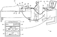
図1は、本発明の実施形態に従う、心臓の3Dナビゲーション及び電気生理学的信号解析システム20の概略的な絵画図である。システム20は、実質的に任意の生理学的パラメータ又はそのようなパラメータの組み合わせを解析するように構成され得る。本明細書の記述において、例として、解析した信号は、心臓内(IC)及び/又は心臓外(体表−BS)心電図(ECG)の電位−時間関係であると想定される。かかる関係を完全に特性化するために、様々な位置において、時間内に相互に信号を参照する(例えばLATマップを生成する間に行われるなどの)必要がある。時間参照は、基準時間(例えば、インスタンス)、例えば、ECG基準信号の各QRS群の最初など(すなわち、心拍毎の最初)と比較して測定することによって実現される。LATマップを生成するための方法は、前述の米国特許第9,050,011号に記載されている。
System Description FIG. 1 is a schematic pictorial diagram of a cardiac 3D navigation and electrophysiological
簡潔性及び明瞭性のために、以下の説明は、特に記述のない限り、システム20がプローブ24を使用して心臓34の実際の電気活動を測定する調査手順を想定する。プローブの遠位端32は、電極22を有すると想定される。測定した信号は、他の用途間で共有して患者26の心臓34の壁組織の少なくとも一部のLATマップを作成するために使用される。
For the sake of brevity and clarity, the following description assumes an investigation procedure in which the
典型的には、プローブ24は、システム20を使用する医師28によって実施されるマッピング手技の間に患者26の身体の中に挿入されるカテーテルを備える。手技中、患者26は、接地電極23に取り付けられると想定される。加えて、電極29が、心臓34の領域にて患者26の皮膚に取り付けられると想定される。
Typically, the
システム20は、システムプロセッサ40によって制御されてもよく、システムプロセッサ40は、メモリ44と通信する処理ユニット42を含む。いくつかの実施形態において、システムプロセッサ40に含まれているメモリ44は、患者26の心臓34の壁組織の少なくとも一部のLAT及び/又は電圧マップ62を記憶する。追加的又は代替的に、メモリ44は、他の患者のマップを記憶し得る。更に、メモリを備える任意の他のプロセッサ(すなわち、必ずしもシステム20の一部ではない)は、1つ又は2つ以上のマップを記憶し得る。プロセッサ40は通常、制御卓46内に載置されており、制御卓46は、通常はマウス又はトラックボールなどのポインティングデバイス39を有する操作制御部38を備え、専門家28はこの操作制御部38を使用してプロセッサと相互作用する。
The
プロセッサ40(具体的には処理ユニット42)は、プローブ追跡モジュール30と、ECGモジュール36と、LAT解析モジュール35を含む不整脈シミュレーションモジュールとを含むソフトウェアを実行して、システム20を操作し、かつ/又はLAT解析モジュール35については(メモリ44内に記憶されたLAT又は調整したLATマップ62を使用して)心臓ペーシングのシミュレーションを実行し、結果として不整脈のモデルを作る。シミュレーションした心臓ペーシングは、シミュレーションしたペーシング用の所望の位置で医師20若しくは副術者が画面上においてクリックすることによって、又は任意の他の方法で実現され得る。シミュレーションしたペーシング用に提示された領域はまた、プロセッサ40によって表示され得る。
The processor 40 (specifically the processing unit 42) executes software including the probe tracking module 30, the
プロセッサ40によって実行される操作の結果は、ディスプレイ48上で医師28に提示され、このディスプレイ48は、典型的には、医師に対するグラフィックユーザインタフェース、電極22によって感知されるECG信号の視覚的表現、及び/又は調査されている間の心臓34の画像若しくはマップを提示する。ある実施形態において、LAT解析モジュール35は、医師に対して、シミュレーションした不整脈が生じたマップ上の1つ又は2つ以上の位置により更新されたLATマップを提示する。ソフトウェアは、例えば、ネットワークを介して、電子的形態でプロセッサ40にダウンロードされてもよく、又はこれに代えて若しくはこれに加えて、磁気メモリ、光メモリ、若しくは電子メモリなどの、非一時的な有形媒体上に提供され、及び/又は記憶されてもよい。
The result of the operation performed by the
ECGモジュール36は、電極22及び電極29からの実際の電気信号を受信するよう連結されている。モジュールは、実際の信号を解析するように構成され、ディスプレイ48上に、標準的なECG形式で、典型的には、時間と共に変動するグラフ式表現で、解析の結果を提示することができる。
The
プローブ追跡モジュール30は、患者26の心臓内で、プローブ24の遠位端32の位置を追跡する。追跡モジュールは、当該技術分野において既知であるいかなるプローブ位置追跡方法を使用してもよい。例えば、モジュール30は、磁場に基づく位置追跡サブシステムを操作し得る(簡潔性のために、このようなサブシステムのコンポーネントは図1には示していない)。
Probe tracking module 30 tracks the position of distal end 32 of
代替的に又は追加的に、追跡モジュール30は、電極23、電極29、及び電極22の間のインピーダンス、並びに、プローブ上に配置する場合がある他の電極に対するインピーダンスを測定することによって、プローブ24を追跡してもよい(この場合には、電極22及び/又は電極29は、ECG信号及び位置追跡信号の双方を提供してもよい)。Biosense Webster(Irvine,California)により製造されるCarto3(登録商標)システムは、磁場位置追跡及びインピーダンス測定の両方を位置追跡に使用する。
Alternatively or additionally, the tracking module 30 may measure the impedance of the
追跡モジュール30を使用してプロセッサ40は、遠位端32の位置を測定することができる。加えて、追跡モジュール30及びECGモジュール36の両方を使用することによって、プロセッサは、遠位端の位置だけでなく、これらの特定の位置において検出される実際の電気信号のLATも測定することができる。明確にするため、本開示及び「特許請求の範囲」において、関連するLAT測定値を有しない遠位端の測定された位置は、本明細書において非LAT位置と呼ばれ、心臓34の内壁組織の三次元の(3D)LATマップの解剖学的コンポーネントを生成するためだけに使用される。対応のLAT測定値を有する遠位端の測定された位置は、LAT位置と呼ばれ、その後に不整脈をシミュレートする試みのために使用される。
Using the tracking module 30, the
不整脈をモデリングするための心臓ペーシングのシミュレーション
図2は、本発明の実施形態による、心臓34のLATマップ62の概略的な絵画図である。簡潔性のために、内壁の組織の完全なマップの部分のみが、図2に示される。LATマップ62は、多重の非LAT位置点64を備えるメッシュとして策定され、その場所は、マップ62の解剖学的コンポーネントを生成するように追跡モジュール30によって評価されてきた。ある実施形態において、プロセッサ40は、接続された平面的な三角形70のメッシュを形成するように、直線的な点間線66によって点64を接続する。接続された三角形70は、心臓内壁組織表面を近似する表面を形成する。解剖学的再構成の他の方法を適用してもよく(例えばCARTO(登録商標)SEG CT/MRIインポートなど)、再構成の他の表現形式を使用してもよい(そのような高速解剖学的マッピングから生成されるメッシュ)。
Simulation of Cardiac Pacing to Model Arrhythmia FIG. 2 is a schematic pictorial illustration of a
マップ62は、LAT位置68も示し、それぞれのLAT位置は、関連付けられたLAT値(単に「LAT」と呼ばれる)を有する。典型的には、LAT位置及びそれらの関連付けられたLATは、マップ62の解剖学的コンポーネントを生成するためにプロセッサ40によって使用された時間からの異なる時間期間に対して評価される。非LAT位置に関しては、他にも理由があるが心臓壁運動を補正するために、LAT位置を基準時間に調整する。理論的には、LAT位置及び非LAT位置の両方の種類の位置が心臓組織壁の上にあるべきなので、LAT位置68は、三角形70の表面と位置合わせされるべきである。
The
心臓の電気活動は、洞房結節において心拍毎の最初に開始し、心筋を通して伝播する電位の波として考えることができる。心臓腔壁上の任意の点において、その点におけるLATは、その点を過ぎて伝播する電位によって生じる。 The electrical activity of the heart can be thought of as a wave of potential that begins at the heartbeat first in the sinoatrial node and propagates through the myocardium. At any point on the heart chamber wall, the LAT at that point is caused by the potential propagating past that point.
LATマップ62において、1つ又は2つ以上のLAT位置68Aは、実際の信号ペーシング位置、すなわち、マップを作成するプロセスにおいて実際の電気信号がカテーテル電極22によって心臓壁組織の中に注入された位置を指定する。LAT位置68Bは、測定された位置を指定し、対応のLAT値を測定するために、そこで結果として(注入された実際の信号に反応して)生じる電気活動を感知した。
In the
ある実施形態において、LAT解析モジュール35は、シミュレーションした電気活動伝播を、この電気活動伝播のシミュレーションにより仮想的にペーシングされた位置68Aを特定するために適用する。この位置68Aは、異なる位置68Bで結果として生じる(すなわち、シミュレーションによって)シミュレーションしたLATパターンと記録された臨床的不整脈との間に最良の一時的適合を提供する。例えば、最良適合を、仮想LATマップ及び仮想時間間隔をもたらす仮想ペーシングと、記録された不整脈の時間間隔特性との間で得ることができる。
In one embodiment, the
いくつかの実施形態において、LAT解析モジュール35は、シミュレーションした刺激の間に、不整脈の潜在源として推定される1つ又は2つ以上の位置でLATマップ62を更新する。LAT解析モジュール35は、LAT位置に、これらの候補位置が不整脈の源である可能性を数量化するグレードを更に割り当てる。LAT解析モジュール35は、1つ又は2つ以上の位置によるグレードで、LATマップ62を数値的かつ/又はグラフィカルに更新する。最も高いグレードを受けるシミュレーションしたペーシング位置68Aは、カテーテル法の間に医師による試行に対する優先位置としての役割を果たして、記録された不整脈に対応する取得信号を生成し得る。続いて、医師は、例えば、そのようなものを分離するために臨床上特定された位置の近くで組織をアブレーションしてもよい。
In some embodiments, the
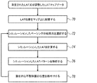
図3は、本発明の実施形態に従って、不整脈が開始し得る位置を、LATマップ62上で特定するための方法を概略的に例示しているフローチャートである。位置は、仮想ペーシングによって生成されるシミュレーションした興奮を生成することによって特定され、予め収集された電気解剖学的信号に基づいて結果を生じる。
FIG. 3 is a flow chart that schematically illustrates a method for identifying on the
手技は、測定されたLATマップ62に基づいて、LATマップ又は調整したLATマップの構築から始めてもよく、そこでは初期工程70において、解析モジュール35が全てのLATデータを計算し、そのデータをメモリ44内に記憶されたマップ62に配置する。次に工程72において、仮想源68A(すなわち、シミュレーションしたペーシングの初期点)は、プロセッサ又はユーザによって選択される。LAT解析モジュール35は、実際の伝播データを考慮し、工程74で仮想源から伝播を計算する。
The procedure may begin with the construction of a LAT map or an adjusted LAT map based on the measured
方法は、ここで解析する工程76に進み、この工程でLAT解析モジュール35は、候補位置が不整脈の源である可能性を数量化するグレードを特定のペーシング位置68Aに割り当てる。ある実施形態において、LAT解析モジュール35は、マップを更新する工程78でグレード又はグラフィカルなものなどの指標を、LATマップ62に追加する。
The method then proceeds to an analysis step 76 where the
手技は、方法が初期点を選択する工程72に戻るときに、別の仮想的にペーシングされた位置68Aを選択するLAT解析モジュール35によって繰り返されてもよい。
The procedure may be repeated by the
図3に示されている例となるフローチャートは、概念を明確化する目的のみで選択されている。代替の実施形態では、代替の電気生理学的マップ及び/又はシミュレーション工程を使用する並びに異なる順序で上記を実行するなどの様々な工程を実行して不整脈の位置を評価してもよい。 The example flow chart shown in FIG. 3 has been selected only for the purpose of clarifying the concept. In alternative embodiments, various steps may be performed to evaluate the location of the arrhythmia, such as using alternative electrophysiological maps and / or simulation steps and performing the above in a different order.
本明細書に記載される実施形態は主に虚血性心室性頻拍の治療に対処するが、本明細書に記載される方法とシステムはまた、任意の巣状不整脈又はリエントリー性不整脈などの他の用途に用いられ得る。 Although the embodiments described herein primarily address the treatment of ischemic ventricular tachycardia, the methods and systems described herein may also include any focal arrhythmia or reentrant arrhythmia, etc. It can be used for other applications.
したがって、上記に述べた実施形態は、例として引用したものであり、また本発明は、上記に具体的に示し説明したものに限定されないことが理解されよう。むしろ本発明の範囲は、上述の様々な特徴の組み合わせ及びその一部の組み合わせの両方、並びに上述の説明を読むことで当業者により想到されるであろう、また従来技術において開示されていないそれらの変形及び修正を含むものである。参照により本特許出願に援用される文献は、これらの援用文献において、いずれかの用語が本明細書において明示的又は暗示的になされた定義と矛盾して定義されている場合には、本明細書における定義のみを考慮するものとする点を除き、本出願の一部と見なすものとする。 Therefore, it will be understood that the embodiments described above are cited by way of example, and that the present invention is not limited to what has been particularly shown and described hereinabove. Rather, the scope of the invention will be conceived by those skilled in the art upon reading both the various combinations of features described above and some of the combinations thereof, as well as those not disclosed in the prior art. Including variations and modifications. Documents incorporated by reference into this patent application are hereby incorporated by reference if any of these terms is defined in contradiction with definitions explicitly or implicitly made herein. It shall be considered part of this application except that only the definitions in the document shall be considered.
〔実施の態様〕
(1) 心臓シミュレーション方法であって、
メモリ内に、患者の心臓の壁組織の少なくとも一部の測定された電気生理学的(EP)マップを記憶することと、
プロセッサにおいて、前記記憶されたEPマップに基づき、実際のペーシングに応じて前記患者の前記心臓の前記壁組織にわたって生じる実際の電気活動をシミュレーションするものである、シミュレーションした電気活動をコンピュータでシミュレーションしたペーシングに応じて計算することと、
前記プロセッサにおいて計算される前記シミュレーションした電気活動に基づいて、不整脈が発生したと疑われる前記心臓の前記壁組織上の1つ又は2つ以上の候補位置を、特定し、ユーザに示すことと、を含む方法。
(2) 前記EPマップを記憶することが、局所興奮時間(LAT)マップ、電圧マップ、及び調整したLATマップのうち1つ又は2つ以上を記憶することを含み、前記1つ又は2つ以上の位置は、前記EPマップ上の電気解剖学的位置を含む、実施態様1に記載の方法。
(3) 前記1つ又は2つ以上の候補位置を特定することが、前記シミュレーションした電気活動を、前記患者の前記心臓で取得した、前記不整脈を呈する前記実際の電気活動と比較することと、前記シミュレーションした電気活動と前記実際の電気活動との間に最良適合をもたらす前記候補位置を見出すことと、を含む、実施態様1に記載の方法。
(4) 前記最良適合を見出すことが、前記シミュレーションした電気活動と前記実際の電気活動との間に最良の一時的適合を見出すことを含む、実施態様3に記載の方法。
(5) 前記1つ又は2つ以上の候補位置に、前記候補位置が前記不整脈の源である可能性を数量化する対応のグレードを割り当てることを含む、実施態様1に記載の方法。
Embodiment
(1) A heart simulation method,
Storing in a memory a measured electrophysiological (EP) map of at least a portion of a patient's heart wall tissue;
A computer-simulated pacing that simulates the actual electrical activity that occurs across the wall tissue of the patient's heart in response to actual pacing in the processor based on the stored EP map Calculating according to
Identifying and presenting to the user one or more candidate locations on the wall tissue of the heart suspected of causing an arrhythmia based on the simulated electrical activity calculated in the processor; Including methods.
(2) storing the EP map includes storing one or more of a local excitation time (LAT) map, a voltage map, and an adjusted LAT map, wherein the one or more 2. The method of embodiment 1, wherein the location comprises an electroanatomical location on the EP map.
(3) identifying the one or more candidate locations is comparing the simulated electrical activity with the actual electrical activity acquired in the heart of the patient and exhibiting the arrhythmia; 2. The method of embodiment 1, comprising finding the candidate location that provides a best fit between the simulated electrical activity and the actual electrical activity.
4. The method of embodiment 3, wherein finding the best fit comprises finding a best temporary fit between the simulated electrical activity and the actual electrical activity.
5. The method of embodiment 1, comprising assigning to the one or more candidate locations a corresponding grade that quantifies the likelihood that the candidate location is a source of the arrhythmia.
(6) 前記1つ又は2つ以上の候補位置に割り当てられた前記グレードをユーザに提示することを含む、実施態様5に記載の方法。
(7) 前記グレードを提示することが、前記1つ又は2つ以上の候補位置に割り当てられた前記グレードで前記EPマップを更新することを含む、実施態様6に記載の方法。
(8) 前記1つ又は2つ以上の候補位置を特定することが、ユーザインタフェースを介して、前記1つ又は2つ以上の候補位置を示すユーザ入力を受信することを含む、実施態様1に記載の方法。
(9) 心臓ペーシングシミュレータであって、
患者の心臓の壁組織の少なくとも一部の測定された電気生理学的(EP)マップを記憶するように構成されたメモリと、
プロセッサであって、
前記記憶されたEPマップに基づき、実際のペーシングに応じて前記患者の前記心臓の前記壁組織にわたって生じる実際の電気活動をシミュレーションするものである、シミュレーションした電気活動をコンピュータでシミュレーションしたペーシングに応じて計算し、
前記プロセッサにおいて計算される前記シミュレーションした電気活動に基づいて、不整脈が発生したと疑われる前記心臓の前記壁組織上の1つ又は2つ以上の候補位置を特定し、ユーザに示すように構成されたプロセッサと、を備えるシミュレータ。
(10) 前記記憶されたEPマップが、局所興奮時間(LAT)マップ、電圧マップ、及び調整したLATマップのうち1つ又は2つ以上を含み、前記1つ又は2つ以上の位置は、前記EPマップ上の電気解剖学的位置を含む、実施態様9に記載のシミュレータ。
6. The method of embodiment 5, comprising presenting the grade assigned to the one or more candidate locations to a user.
7. The method of embodiment 6, wherein presenting the grade comprises updating the EP map with the grade assigned to the one or more candidate locations.
(8) The embodiment 1 wherein identifying the one or more candidate positions includes receiving user input indicating the one or more candidate positions via a user interface. The method described.
(9) A cardiac pacing simulator,
A memory configured to store a measured electrophysiological (EP) map of at least a portion of a patient's heart wall tissue;
A processor,
Based on the stored EP map, simulating actual electrical activity that occurs across the wall tissue of the patient's heart in response to actual pacing, in response to pacing that simulates the simulated electrical activity in a computer Calculate
Based on the simulated electrical activity calculated in the processor, one or more candidate locations on the wall tissue of the heart suspected of having an arrhythmia are identified and configured to be shown to the user. And a processor.
(10) The stored EP map includes one or more of a local excitation time (LAT) map, a voltage map, and an adjusted LAT map, wherein the one or more positions are the Embodiment 10. The simulator of embodiment 9 comprising an electroanatomical location on the EP map.
(11) 前記プロセッサが、前記シミュレーションした電気活動を、前記患者の前記心臓で取得した、前記不整脈を呈する前記実際の電気活動と比較し、前記シミュレーションした電気活動と前記実際の電気活動との間に最良適合をもたらす前記候補位置を見出すことによって、前記1つ又は2つ以上の候補位置を特定するように構成されている、実施態様9に記載のシミュレータ。
(12) 前記プロセッサが、シミュレーションした電気活動と前記実際の電気活動との間に最良の一時的適合を見出すことによって前記最良適合を見出すように構成されている、実施態様11に記載のシミュレータ。
(13) 前記プロセッサは、前記1つ又は2つ以上の候補位置に、前記候補位置が前記不整脈の源である可能性を数量化する対応のグレードを割り当てるように構成されている、実施態様9に記載のシミュレータ。
(14) 前記プロセッサが、前記1つ又は2つ以上の候補位置に割り当てられた前記グレードをユーザに提示するように更に構成されている、実施態様13に記載のシミュレータ。
(15) 前記プロセッサが、前記1つ又は2つ以上の候補位置に割り当てられた前記グレードで前記EPマップを更新することによって前記グレードを提示するように構成されている、実施態様14に記載のシミュレータ。
(11) The processor compares the simulated electrical activity with the actual electrical activity acquired in the heart of the patient and exhibiting the arrhythmia, and between the simulated electrical activity and the actual electrical activity. 10. The simulator of embodiment 9, wherein the simulator is configured to identify the one or more candidate positions by finding the candidate position that provides the best fit.
12. The simulator of embodiment 11 wherein the processor is configured to find the best fit by finding the best temporal fit between simulated electrical activity and the actual electrical activity.
(13) Embodiment 9 wherein the processor is configured to assign a corresponding grade that quantifies the likelihood that the candidate location is a source of the arrhythmia to the one or more candidate locations. Simulator described in 1.
(14) The simulator of embodiment 13, wherein the processor is further configured to present to the user the grades assigned to the one or more candidate positions.
15. The embodiment of claim 14, wherein the processor is configured to present the grade by updating the EP map with the grade assigned to the one or more candidate locations. Simulator.
(16) 前記1つ又は2つ以上の候補位置を示すユーザ入力を受信するように構成されたユーザインタフェースを更に含む、実施態様9に記載のシミュレータ。 16. The simulator of embodiment 9, further comprising a user interface configured to receive user input indicating the one or more candidate locations.
Claims (16)
メモリ内に、患者の心臓の壁組織の少なくとも一部の測定された電気生理学的(EP)マップを記憶することと、
プロセッサにおいて、前記記憶されたEPマップに基づき、実際のペーシングに応じて前記患者の前記心臓の前記壁組織にわたって生じる実際の電気活動をシミュレーションするものである、シミュレーションした電気活動をコンピュータでシミュレーションしたペーシングに応じて計算することと、
前記プロセッサにおいて計算される前記シミュレーションした電気活動に基づいて、不整脈が発生したと疑われる前記心臓の前記壁組織上の1つ又は2つ以上の候補位置を、特定し、ユーザに示すことと、を含む方法。 A heart simulation method,
Storing in a memory a measured electrophysiological (EP) map of at least a portion of a patient's heart wall tissue;
A computer-simulated pacing that simulates the actual electrical activity that occurs across the wall tissue of the patient's heart in response to actual pacing in the processor based on the stored EP map Calculating according to
Identifying and presenting to the user one or more candidate locations on the wall tissue of the heart suspected of causing an arrhythmia based on the simulated electrical activity calculated in the processor; Including methods.
患者の心臓の壁組織の少なくとも一部の測定された電気生理学的(EP)マップを記憶するように構成されたメモリと、
プロセッサであって、
前記記憶されたEPマップに基づき、実際のペーシングに応じて前記患者の前記心臓の前記壁組織にわたって生じる実際の電気活動をシミュレーションするものである、シミュレーションした電気活動をコンピュータでシミュレーションしたペーシングに応じて計算し、
前記プロセッサにおいて計算される前記シミュレーションした電気活動に基づいて、不整脈が発生したと疑われる前記心臓の前記壁組織上の1つ又は2つ以上の候補位置を特定し、ユーザに示すように構成されたプロセッサと、を備えるシミュレータ。 A cardiac pacing simulator,
A memory configured to store a measured electrophysiological (EP) map of at least a portion of a patient's heart wall tissue;
A processor,
Based on the stored EP map, simulating actual electrical activity that occurs across the wall tissue of the patient's heart in response to actual pacing, in response to pacing that simulates the simulated electrical activity in a computer Calculate
Based on the simulated electrical activity calculated in the processor, one or more candidate locations on the wall tissue of the heart suspected of having an arrhythmia are identified and configured to be shown to the user. And a processor.
Applications Claiming Priority (2)
| Application Number | Priority Date | Filing Date | Title |
|---|---|---|---|
| US15/913,483 | 2018-03-06 | ||
| US15/913,483 US11482338B2 (en) | 2018-03-06 | 2018-03-06 | Simulation of heart pacing for modeling arrhythmia |
Publications (2)
| Publication Number | Publication Date |
|---|---|
| JP2019155093A true JP2019155093A (en) | 2019-09-19 |
| JP2019155093A5 JP2019155093A5 (en) | 2024-02-13 |
Family
ID=65818160
Family Applications (1)
| Application Number | Title | Priority Date | Filing Date |
|---|---|---|---|
| JP2019039319A Pending JP2019155093A (en) | 2018-03-06 | 2019-03-05 | Simulation of heart pacing for modeling arrhythmia |
Country Status (7)
| Country | Link |
|---|---|
| US (1) | US11482338B2 (en) |
| EP (1) | EP3537444A1 (en) |
| JP (1) | JP2019155093A (en) |
| CN (1) | CN110227209A (en) |
| AU (1) | AU2019200926A1 (en) |
| CA (1) | CA3035472A1 (en) |
| IL (1) | IL264803B2 (en) |
Families Citing this family (2)
| Publication number | Priority date | Publication date | Assignee | Title |
|---|---|---|---|---|
| US11445935B2 (en) * | 2018-11-26 | 2022-09-20 | Biosense Webster (Israel) Ltd. | Finding the origin of an arrythmia |
| US11607272B2 (en) * | 2019-11-12 | 2023-03-21 | Biosense Webster (Israel) Ltd. | Visual route indication for activation clusters |
Citations (5)
| Publication number | Priority date | Publication date | Assignee | Title |
|---|---|---|---|---|
| US20070219452A1 (en) * | 2006-03-16 | 2007-09-20 | Cohen Richard J | Method and apparatus for the guided ablative therapy of fast ventricular arrhythmia |
| US20090112109A1 (en) * | 2007-08-31 | 2009-04-30 | Pawel Kuklik | Reconstruction of geometry of a body component and analysis of spatial distribution of electrophysiological values |
| JP2014512201A (en) * | 2011-02-11 | 2014-05-22 | ザ・ジョンズ・ホプキンス・ユニバーシティー | System and method for planning cardiac surgery by patient |
| US20160317055A1 (en) * | 2013-12-12 | 2016-11-03 | Biosig Technologies, Inc. | Systems and methods for evaluation of electrophysiology systems |
| WO2017203250A1 (en) * | 2016-05-25 | 2017-11-30 | King's College London | Method and system for predicting heart tissue activation |
Family Cites Families (23)
| Publication number | Priority date | Publication date | Assignee | Title |
|---|---|---|---|---|
| CA1292572C (en) | 1988-10-25 | 1991-11-26 | Fernando C. Lebron | Cardiac mapping system simulator |
| US5203326A (en) * | 1991-12-18 | 1993-04-20 | Telectronics Pacing Systems, Inc. | Antiarrhythmia pacer using antiarrhythmia pacing and autonomic nerve stimulation therapy |
| US5722416A (en) * | 1995-02-17 | 1998-03-03 | Ep Technologies, Inc. | Systems and methods for analyzing biopotential morphologies in heart tissue to locate potential ablation sites |
| US20050202384A1 (en) | 2001-04-20 | 2005-09-15 | Medtronic, Inc. | Interactive computer model of the heart |
| US7123954B2 (en) * | 2002-09-19 | 2006-10-17 | Sanjiv Mathur Narayan | Method for classifying and localizing heart arrhythmias |
| US7828735B2 (en) | 2006-05-11 | 2010-11-09 | The Trustees Of Columbia In The City Of New York | Methods for providing diagnostic information using endocardial surface data for a patient's heart |
| US8706195B2 (en) * | 2007-05-08 | 2014-04-22 | Mediguide Ltd. | Method for producing an electrophysiological map of the heart |
| US8478393B2 (en) * | 2008-11-10 | 2013-07-02 | Cardioinsight Technologies, Inc. | Visualization of electrophysiology data |
| US8340766B2 (en) * | 2010-10-07 | 2012-12-25 | St. Jude Medical, Atrial Fibrillation Division, Inc. | Method and system for identifying cardiac arrhythmia driver sites |
| CN103415320B (en) | 2011-02-01 | 2016-08-10 | 布里格姆女子医院有限公司 | Use ventricular activation simulation and body surface ECG record to carry out cardiac resynchronization therapy and control the System and method for that parameter generates |
| US8909502B2 (en) * | 2011-12-29 | 2014-12-09 | St. Jude Medical, Atrial Fibrillation Division, Inc. | Method and system for constructing an electrophysiology map |
| US9277970B2 (en) * | 2012-07-19 | 2016-03-08 | Siemens Aktiengesellschaft | System and method for patient specific planning and guidance of ablative procedures for cardiac arrhythmias |
| US9050011B2 (en) | 2012-12-26 | 2015-06-09 | Biosense Webster (Israel) Ltd. | Removal of artifacts from map data |
| US9463072B2 (en) * | 2013-08-09 | 2016-10-11 | Siemens Aktiengesellschaft | System and method for patient specific planning and guidance of electrophysiology interventions |
| US9642674B2 (en) * | 2013-09-12 | 2017-05-09 | Biosense Webster (Israel) Ltd. | Method for mapping ventricular/atrial premature beats during sinus rhythm |
| US9990470B2 (en) * | 2013-10-30 | 2018-06-05 | St. Jude Medical, Cardiology Division, Inc. | Cardiac mapping system and method for voltage-based evaluation of electrograms |
| US10496729B2 (en) | 2014-02-25 | 2019-12-03 | Siemens Healthcare Gmbh | Method and system for image-based estimation of multi-physics parameters and their uncertainty for patient-specific simulation of organ function |
| CN106535741B (en) * | 2014-04-02 | 2020-09-29 | 西门子保健有限责任公司 | System and method for characterizing electrical properties of the heart from medical images and body surface potentials |
| US10296707B2 (en) | 2014-04-10 | 2019-05-21 | Siemens Healthcare Gmbh | System and method for patient-specific image-based guidance of cardiac arrhythmia therapies |
| US9589379B2 (en) | 2014-06-24 | 2017-03-07 | Siemens Healthcare Gmbh | System and method for visualization of cardiac changes under various pacing conditions |
| US10925511B2 (en) | 2014-07-24 | 2021-02-23 | Cardiosolv Ablation Technologies, Inc. | System and method for cardiac ablation |
| US10354758B2 (en) * | 2014-08-28 | 2019-07-16 | Siemens Healthcare Gmbh | System and method for patient-specific image-based simulation of atrial electrophysiology |
| US10136828B2 (en) | 2016-03-31 | 2018-11-27 | Biosense Webster (Israel) Ltd. | Mapping of atrial fibrillation |
-
2018
- 2018-03-06 US US15/913,483 patent/US11482338B2/en active Active
-
2019
- 2019-02-11 AU AU2019200926A patent/AU2019200926A1/en not_active Abandoned
- 2019-02-12 IL IL264803A patent/IL264803B2/en unknown
- 2019-03-04 CA CA3035472A patent/CA3035472A1/en not_active Abandoned
- 2019-03-05 JP JP2019039319A patent/JP2019155093A/en active Pending
- 2019-03-05 EP EP19160745.6A patent/EP3537444A1/en active Pending
- 2019-03-06 CN CN201910167538.4A patent/CN110227209A/en active Pending
Patent Citations (5)
| Publication number | Priority date | Publication date | Assignee | Title |
|---|---|---|---|---|
| US20070219452A1 (en) * | 2006-03-16 | 2007-09-20 | Cohen Richard J | Method and apparatus for the guided ablative therapy of fast ventricular arrhythmia |
| US20090112109A1 (en) * | 2007-08-31 | 2009-04-30 | Pawel Kuklik | Reconstruction of geometry of a body component and analysis of spatial distribution of electrophysiological values |
| JP2014512201A (en) * | 2011-02-11 | 2014-05-22 | ザ・ジョンズ・ホプキンス・ユニバーシティー | System and method for planning cardiac surgery by patient |
| US20160317055A1 (en) * | 2013-12-12 | 2016-11-03 | Biosig Technologies, Inc. | Systems and methods for evaluation of electrophysiology systems |
| WO2017203250A1 (en) * | 2016-05-25 | 2017-11-30 | King's College London | Method and system for predicting heart tissue activation |
Non-Patent Citations (1)
| Title |
|---|
| YU LONG ET AL.: ""Non-invasive imaging of ventricular activation during pacing and arrhythmia: Methods and validatio", 2016 38TH ANNUAL INTERNATIONAL CONFERENCE OF THE IEEE ENGINEERING IN MEDICINE AND BIOLOGY SOCIETY (E, JPN6022052919, 20 August 2016 (2016-08-20), pages 113 - 116, XP032979107, ISSN: 0004942372, DOI: 10.1109/EMBC.2016.7590653 * |
Also Published As
| Publication number | Publication date |
|---|---|
| IL264803B2 (en) | 2023-07-01 |
| AU2019200926A1 (en) | 2019-09-26 |
| CN110227209A (en) | 2019-09-13 |
| US20190279773A1 (en) | 2019-09-12 |
| EP3537444A1 (en) | 2019-09-11 |
| CA3035472A1 (en) | 2019-09-06 |
| IL264803A (en) | 2019-05-30 |
| IL264803B1 (en) | 2023-03-01 |
| US11482338B2 (en) | 2022-10-25 |
Similar Documents
| Publication | Publication Date | Title |
|---|---|---|
| US11826148B2 (en) | Sensing zone for spatially relevant electrical information | |
| US10076260B2 (en) | Integrated analysis of electrophysiological data | |
| US10485438B2 (en) | System and method for targeting heart rhythm disorders using shaped ablation | |
| US10835139B2 (en) | Method to determine wavefront vector flow-field and vorticity from spatially-distributed recordings | |
| US10342620B2 (en) | Efficient treatment of atrial fibrillation using three-dimensional electrical potential model | |
| JP5135333B2 (en) | System and method for mapping electrophysiological information to complex geometry | |
| CA2357729C (en) | Method and apparatus for characterizing cardiac tissue from local electrograms | |
| JP5805204B2 (en) | System for assessing cardiac function | |
| JP5281570B2 (en) | Non-contact cardiac mapping including catheter movement and multi-beat integration | |
| JP2019503264A (en) | Method and system for statistically analyzing and mapping electrograms for local abnormal ventricular activity | |
| JP6300911B2 (en) | System and method for cardiac mapping for bidirectional activation detection of electrograms | |
| US11571160B2 (en) | Methods and systems for wavelength mapping cardiac fibrillation and optimizing ablation lesion placement | |
| JP6152474B2 (en) | System and method for generating an electrophysiological map | |
| JP2018514279A (en) | System and method for real-time electrophysiological mapping | |
| RU2758750C1 (en) | Re-annotation of electroanatomic map | |
| JP2019155093A (en) | Simulation of heart pacing for modeling arrhythmia | |
| Sra et al. | Identifying the third dimension in 2D fluoroscopy to create 3D cardiac maps | |
| JP2018510048A (en) | Method and system for identifying a gorge in a three-dimensional map | |
| US11553867B2 (en) | Systems and methods for displaying EP maps using confidence metrics | |
| US20220378292A1 (en) | Electrical activity-based procedure guidance | |
| JP2021159762A (en) | Propagation map of cardiac chamber with areas demonstrating fractionated electrograms | |
| RU2771797C2 (en) | Iterative coherent mapping of electrophysiological activation of heart, including effect of re-entry | |
| US11844616B2 (en) | Enhanced visualization of organ electrical activity | |
| RU2772201C2 (en) | Iterative coherent mapping of electrophysiological activation of heart, including scar effects | |
| US20200211691A1 (en) | Disease guided insertion for implants |
Legal Events
| Date | Code | Title | Description |
|---|---|---|---|
| A621 | Written request for application examination |
Free format text: JAPANESE INTERMEDIATE CODE: A621 Effective date: 20220210 |
|
| A131 | Notification of reasons for refusal |
Free format text: JAPANESE INTERMEDIATE CODE: A131 Effective date: 20221213 |
|
| A601 | Written request for extension of time |
Free format text: JAPANESE INTERMEDIATE CODE: A601 Effective date: 20230313 |
|
| A521 | Request for written amendment filed |
Free format text: JAPANESE INTERMEDIATE CODE: A523 Effective date: 20230510 |
|
| A131 | Notification of reasons for refusal |
Free format text: JAPANESE INTERMEDIATE CODE: A131 Effective date: 20230606 |
|
| A521 | Request for written amendment filed |
Free format text: JAPANESE INTERMEDIATE CODE: A523 Effective date: 20230904 |
|
| A524 | Written submission of copy of amendment under article 19 pct |
Free format text: JAPANESE INTERMEDIATE CODE: A524 Effective date: 20230904 |
|
| A131 | Notification of reasons for refusal |
Free format text: JAPANESE INTERMEDIATE CODE: A131 Effective date: 20231107 |
|
| A521 | Request for written amendment filed |
Free format text: JAPANESE INTERMEDIATE CODE: A523 Effective date: 20240202 |
|
| A524 | Written submission of copy of amendment under article 19 pct |
Free format text: JAPANESE INTERMEDIATE CODE: A524 Effective date: 20240202 |