JP2019154883A - Medical image processing apparatus, medical observation apparatus, and image processing method - Google Patents
Medical image processing apparatus, medical observation apparatus, and image processing method Download PDFInfo
- Publication number
- JP2019154883A JP2019154883A JP2018047492A JP2018047492A JP2019154883A JP 2019154883 A JP2019154883 A JP 2019154883A JP 2018047492 A JP2018047492 A JP 2018047492A JP 2018047492 A JP2018047492 A JP 2018047492A JP 2019154883 A JP2019154883 A JP 2019154883A
- Authority
- JP
- Japan
- Prior art keywords
- medical
- display device
- image processing
- image
- medical observation
- Prior art date
- Legal status (The legal status is an assumption and is not a legal conclusion. Google has not performed a legal analysis and makes no representation as to the accuracy of the status listed.)
- Pending
Links
Images


Classifications
-
- A—HUMAN NECESSITIES
- A61—MEDICAL OR VETERINARY SCIENCE; HYGIENE
- A61B—DIAGNOSIS; SURGERY; IDENTIFICATION
- A61B1/00—Instruments for performing medical examinations of the interior of cavities or tubes of the body by visual or photographical inspection, e.g. endoscopes; Illuminating arrangements therefor
- A61B1/00002—Operational features of endoscopes
- A61B1/00004—Operational features of endoscopes characterised by electronic signal processing
- A61B1/00009—Operational features of endoscopes characterised by electronic signal processing of image signals during a use of endoscope
-
- A—HUMAN NECESSITIES
- A61—MEDICAL OR VETERINARY SCIENCE; HYGIENE
- A61B—DIAGNOSIS; SURGERY; IDENTIFICATION
- A61B1/00—Instruments for performing medical examinations of the interior of cavities or tubes of the body by visual or photographical inspection, e.g. endoscopes; Illuminating arrangements therefor
- A61B1/00002—Operational features of endoscopes
- A61B1/00043—Operational features of endoscopes provided with output arrangements
- A61B1/00045—Display arrangement
- A61B1/00048—Constructional features of the display
-
- A—HUMAN NECESSITIES
- A61—MEDICAL OR VETERINARY SCIENCE; HYGIENE
- A61B—DIAGNOSIS; SURGERY; IDENTIFICATION
- A61B1/00—Instruments for performing medical examinations of the interior of cavities or tubes of the body by visual or photographical inspection, e.g. endoscopes; Illuminating arrangements therefor
- A61B1/00002—Operational features of endoscopes
- A61B1/00043—Operational features of endoscopes provided with output arrangements
- A61B1/00045—Display arrangement
- A61B1/0005—Display arrangement combining images e.g. side-by-side, superimposed or tiled
-
- A—HUMAN NECESSITIES
- A61—MEDICAL OR VETERINARY SCIENCE; HYGIENE
- A61B—DIAGNOSIS; SURGERY; IDENTIFICATION
- A61B1/00—Instruments for performing medical examinations of the interior of cavities or tubes of the body by visual or photographical inspection, e.g. endoscopes; Illuminating arrangements therefor
- A61B1/00163—Optical arrangements
- A61B1/00188—Optical arrangements with focusing or zooming features
-
- A—HUMAN NECESSITIES
- A61—MEDICAL OR VETERINARY SCIENCE; HYGIENE
- A61B—DIAGNOSIS; SURGERY; IDENTIFICATION
- A61B1/00—Instruments for performing medical examinations of the interior of cavities or tubes of the body by visual or photographical inspection, e.g. endoscopes; Illuminating arrangements therefor
- A61B1/00163—Optical arrangements
- A61B1/00193—Optical arrangements adapted for stereoscopic vision
-
- A—HUMAN NECESSITIES
- A61—MEDICAL OR VETERINARY SCIENCE; HYGIENE
- A61B—DIAGNOSIS; SURGERY; IDENTIFICATION
- A61B1/00—Instruments for performing medical examinations of the interior of cavities or tubes of the body by visual or photographical inspection, e.g. endoscopes; Illuminating arrangements therefor
- A61B1/04—Instruments for performing medical examinations of the interior of cavities or tubes of the body by visual or photographical inspection, e.g. endoscopes; Illuminating arrangements therefor combined with photographic or television appliances
- A61B1/045—Control thereof
-
- A—HUMAN NECESSITIES
- A61—MEDICAL OR VETERINARY SCIENCE; HYGIENE
- A61B—DIAGNOSIS; SURGERY; IDENTIFICATION
- A61B34/00—Computer-aided surgery; Manipulators or robots specially adapted for use in surgery
- A61B34/30—Surgical robots
-
- A—HUMAN NECESSITIES
- A61—MEDICAL OR VETERINARY SCIENCE; HYGIENE
- A61B—DIAGNOSIS; SURGERY; IDENTIFICATION
- A61B90/00—Instruments, implements or accessories specially adapted for surgery or diagnosis and not covered by any of the groups A61B1/00 - A61B50/00, e.g. for luxation treatment or for protecting wound edges
- A61B90/36—Image-producing devices or illumination devices not otherwise provided for
- A61B90/37—Surgical systems with images on a monitor during operation
-
- G—PHYSICS
- G16—INFORMATION AND COMMUNICATION TECHNOLOGY [ICT] SPECIALLY ADAPTED FOR SPECIFIC APPLICATION FIELDS
- G16H—HEALTHCARE INFORMATICS, i.e. INFORMATION AND COMMUNICATION TECHNOLOGY [ICT] SPECIALLY ADAPTED FOR THE HANDLING OR PROCESSING OF MEDICAL OR HEALTHCARE DATA
- G16H20/00—ICT specially adapted for therapies or health-improving plans, e.g. for handling prescriptions, for steering therapy or for monitoring patient compliance
- G16H20/40—ICT specially adapted for therapies or health-improving plans, e.g. for handling prescriptions, for steering therapy or for monitoring patient compliance relating to mechanical, radiation or invasive therapies, e.g. surgery, laser therapy, dialysis or acupuncture
-
- G—PHYSICS
- G16—INFORMATION AND COMMUNICATION TECHNOLOGY [ICT] SPECIALLY ADAPTED FOR SPECIFIC APPLICATION FIELDS
- G16H—HEALTHCARE INFORMATICS, i.e. INFORMATION AND COMMUNICATION TECHNOLOGY [ICT] SPECIALLY ADAPTED FOR THE HANDLING OR PROCESSING OF MEDICAL OR HEALTHCARE DATA
- G16H30/00—ICT specially adapted for the handling or processing of medical images
- G16H30/40—ICT specially adapted for the handling or processing of medical images for processing medical images, e.g. editing
-
- A—HUMAN NECESSITIES
- A61—MEDICAL OR VETERINARY SCIENCE; HYGIENE
- A61B—DIAGNOSIS; SURGERY; IDENTIFICATION
- A61B1/00—Instruments for performing medical examinations of the interior of cavities or tubes of the body by visual or photographical inspection, e.g. endoscopes; Illuminating arrangements therefor
- A61B1/06—Instruments for performing medical examinations of the interior of cavities or tubes of the body by visual or photographical inspection, e.g. endoscopes; Illuminating arrangements therefor with illuminating arrangements
- A61B1/0661—Endoscope light sources
- A61B1/0676—Endoscope light sources at distal tip of an endoscope
-
- A—HUMAN NECESSITIES
- A61—MEDICAL OR VETERINARY SCIENCE; HYGIENE
- A61B—DIAGNOSIS; SURGERY; IDENTIFICATION
- A61B34/00—Computer-aided surgery; Manipulators or robots specially adapted for use in surgery
- A61B34/20—Surgical navigation systems; Devices for tracking or guiding surgical instruments, e.g. for frameless stereotaxis
- A61B2034/2046—Tracking techniques
- A61B2034/2059—Mechanical position encoders
-
- A—HUMAN NECESSITIES
- A61—MEDICAL OR VETERINARY SCIENCE; HYGIENE
- A61B—DIAGNOSIS; SURGERY; IDENTIFICATION
- A61B90/00—Instruments, implements or accessories specially adapted for surgery or diagnosis and not covered by any of the groups A61B1/00 - A61B50/00, e.g. for luxation treatment or for protecting wound edges
- A61B90/30—Devices for illuminating a surgical field, the devices having an interrelation with other surgical devices or with a surgical procedure
- A61B2090/304—Devices for illuminating a surgical field, the devices having an interrelation with other surgical devices or with a surgical procedure using chemi-luminescent materials
-
- A—HUMAN NECESSITIES
- A61—MEDICAL OR VETERINARY SCIENCE; HYGIENE
- A61B—DIAGNOSIS; SURGERY; IDENTIFICATION
- A61B90/00—Instruments, implements or accessories specially adapted for surgery or diagnosis and not covered by any of the groups A61B1/00 - A61B50/00, e.g. for luxation treatment or for protecting wound edges
- A61B90/36—Image-producing devices or illumination devices not otherwise provided for
- A61B90/37—Surgical systems with images on a monitor during operation
- A61B2090/371—Surgical systems with images on a monitor during operation with simultaneous use of two cameras
-
- A—HUMAN NECESSITIES
- A61—MEDICAL OR VETERINARY SCIENCE; HYGIENE
- A61B—DIAGNOSIS; SURGERY; IDENTIFICATION
- A61B90/00—Instruments, implements or accessories specially adapted for surgery or diagnosis and not covered by any of the groups A61B1/00 - A61B50/00, e.g. for luxation treatment or for protecting wound edges
- A61B90/36—Image-producing devices or illumination devices not otherwise provided for
- A61B90/37—Surgical systems with images on a monitor during operation
- A61B2090/372—Details of monitor hardware
-
- A—HUMAN NECESSITIES
- A61—MEDICAL OR VETERINARY SCIENCE; HYGIENE
- A61B—DIAGNOSIS; SURGERY; IDENTIFICATION
- A61B90/00—Instruments, implements or accessories specially adapted for surgery or diagnosis and not covered by any of the groups A61B1/00 - A61B50/00, e.g. for luxation treatment or for protecting wound edges
- A61B90/50—Supports for surgical instruments, e.g. articulated arms
- A61B2090/502—Headgear, e.g. helmet, spectacles
-
- A—HUMAN NECESSITIES
- A61—MEDICAL OR VETERINARY SCIENCE; HYGIENE
- A61B—DIAGNOSIS; SURGERY; IDENTIFICATION
- A61B90/00—Instruments, implements or accessories specially adapted for surgery or diagnosis and not covered by any of the groups A61B1/00 - A61B50/00, e.g. for luxation treatment or for protecting wound edges
- A61B90/20—Surgical microscopes characterised by non-optical aspects
-
- A—HUMAN NECESSITIES
- A61—MEDICAL OR VETERINARY SCIENCE; HYGIENE
- A61B—DIAGNOSIS; SURGERY; IDENTIFICATION
- A61B90/00—Instruments, implements or accessories specially adapted for surgery or diagnosis and not covered by any of the groups A61B1/00 - A61B50/00, e.g. for luxation treatment or for protecting wound edges
- A61B90/50—Supports for surgical instruments, e.g. articulated arms
Landscapes
- Health & Medical Sciences (AREA)
- Life Sciences & Earth Sciences (AREA)
- Surgery (AREA)
- Engineering & Computer Science (AREA)
- Nuclear Medicine, Radiotherapy & Molecular Imaging (AREA)
- General Health & Medical Sciences (AREA)
- Public Health (AREA)
- Medical Informatics (AREA)
- Radiology & Medical Imaging (AREA)
- Animal Behavior & Ethology (AREA)
- Veterinary Medicine (AREA)
- Biomedical Technology (AREA)
- Heart & Thoracic Surgery (AREA)
- Molecular Biology (AREA)
- Pathology (AREA)
- Physics & Mathematics (AREA)
- Optics & Photonics (AREA)
- Biophysics (AREA)
- Epidemiology (AREA)
- Primary Health Care (AREA)
- Gynecology & Obstetrics (AREA)
- Oral & Maxillofacial Surgery (AREA)
- Signal Processing (AREA)
- Robotics (AREA)
- Urology & Nephrology (AREA)
- Endoscopes (AREA)
- Closed-Circuit Television Systems (AREA)
Abstract
Description
本開示は、医療用画像処理装置、医療用観察装置、および画像処理方法に関する。 The present disclosure relates to a medical image processing apparatus, a medical observation apparatus, and an image processing method.
近年、医療現場においては、例えば、脳神経外科手術などの微細手術(マイクロサージャリ)をサポートするためや、内視鏡手術を行うために、患部などの観察対象を拡大観察することが可能な医療用観察装置が用いられる場合がある。医療用観察装置としては、例えば、光学式の顕微鏡を備える医療用観察装置と、電子撮像式の顕微鏡として機能する撮像デバイスを備える医療用観察装置とが挙げられる。以下では、上記光学式の顕微鏡を備える医療用観察装置を「光学式の医療用観察装置」と示す。また、以下では、上記撮像デバイスを備える医療用観察装置を、「電子撮像式の医療用観察装置」または単に「医療用観察装置」と示す場合がある。また、以下では、医療用観察装置が備える撮像デバイスにより観察対象が撮像された撮像画像(動画像、または、静止画像。以下、同様とする。)を「医療用撮像画像」と示す。 In recent years, in medical practice, for example, medical treatment capable of magnifying and observing an observation target such as an affected part in order to support microsurgery such as neurosurgery or to perform endoscopic surgery. An observation device may be used. Examples of the medical observation apparatus include a medical observation apparatus including an optical microscope and a medical observation apparatus including an imaging device that functions as an electronic imaging microscope. Hereinafter, the medical observation apparatus including the optical microscope is referred to as an “optical medical observation apparatus”. Hereinafter, a medical observation apparatus including the imaging device may be referred to as an “electronic imaging type medical observation apparatus” or simply “medical observation apparatus”. In the following, a captured image (moving image or still image; the same applies hereinafter) in which an observation target is captured by an imaging device included in the medical observation apparatus is referred to as a “medical captured image”.
電子撮像式の医療用観察装置は、撮像デバイスの高画質化や撮像された画像が表示される表示装置の高画質化などに伴い、光学式の医療用観察装置と同等以上の画質が得られるようになっている。また、電子撮像式の医療用観察装置を用いる利用者(例えば、術者や術者の助手などの医療従事者)は、光学式の医療用観察装置を用いる場合のように光学式の顕微鏡を構成する接眼レンズを覗き込む必要はないので、撮像デバイスの位置をより自由に移動させることが可能である。そのため、電子撮像式の医療用観察装置が用いられることによって微細手術などをより柔軟にサポートすることができるという利点があり、医療現場での電子撮像式の医療用観察装置の利用が進んでいる。 An electronic imaging medical observation apparatus can obtain an image quality equivalent to or higher than that of an optical medical observation apparatus in accordance with an improvement in image quality of an imaging device and an increase in image quality of a display device on which a captured image is displayed. It is like that. In addition, a user who uses an electronic imaging medical observation device (for example, a medical worker such as an operator or a surgeon's assistant) uses an optical microscope as in the case of using an optical medical observation device. Since it is not necessary to look into the eyepiece lens, the position of the imaging device can be moved more freely. For this reason, the use of an electronic imaging medical observation apparatus has an advantage that microsurgery and the like can be supported more flexibly, and the use of the electronic imaging medical observation apparatus in a medical field is progressing. .
このような中、内視鏡手術に用いられる表示装置に関する技術が開発されている。“画面回転操作部を用いた施術者の回転要求に基づき、表示装置の表示画面を時計回り方向および反時計回り方向に回転させる技術”としては、例えば下記の特許文献1に記載の技術が挙げられる。 Under such circumstances, techniques relating to display devices used for endoscopic surgery have been developed. “Technology for rotating the display screen of the display device in the clockwise direction and the counterclockwise direction based on the rotation request of the practitioner using the screen rotation operation unit” includes, for example, the technique described in Patent Document 1 below. It is done.
医療用観察装置が用いられる手術では、1つの撮像デバイスで撮像された医療用撮像画像を複数の術者が見て手技を行う場合がある。例えば執刀医と助手という2名の術者で手技が行われる例を挙げると、執刀医および助手それぞれの正面に表示装置が配置される。このとき、撮像デバイスの天地方向は、執刀医の向きに合わせることが一般的である。 In a surgery in which a medical observation apparatus is used, a plurality of surgeons may perform a procedure by viewing a medical captured image captured by one imaging device. For example, when two surgeons, a surgeon and an assistant, perform an operation, a display device is arranged in front of each of the surgeon and the assistant. At this time, the vertical direction of the imaging device is generally matched to the direction of the surgeon.
ここで、執刀医の位置では、撮像デバイスの天地と術者の向いている方向と、表示装置の配置方向とが揃っている。そのため、執刀医の正面に配置されている表示装置の表示画面の下側には執刀医自身の手が写ることとなり、執刀医は、違和感なく手技を行うことができる。 Here, at the position of the surgeon, the orientation of the imaging device facing the operator and the operator is aligned with the arrangement direction of the display device. Therefore, the surgeon's own hand is reflected on the lower side of the display screen of the display device arranged in front of the surgeon, and the surgeon can perform the procedure without a sense of incongruity.
しかしながら、助手の位置では、撮像デバイスの天地と術者の向いている方向と、表示装置の配置方向とが揃っていない。そのため、助手の正面に配置されている表示装置の表示画面の下側には助手自身の手が写らず、表示画面内の天地方向が術者の向いている方向とズレてしまい、その結果、助手による直感的な手技が妨げられる場合があった。 However, at the position of the assistant, the orientation of the imaging device facing the operator and the operator is not aligned with the arrangement direction of the display device. Therefore, the assistant's own hand is not reflected on the lower side of the display screen of the display device arranged in front of the assistant, the top and bottom direction in the display screen is shifted from the direction that the operator is facing, In some cases, an intuitive procedure by an assistant was hindered.
上記の例に示すように、医療用観察装置が用いられる手術では、助手のような一部の医療従事者が直感的な手技を行うことができない可能性がある。そして、医療用観察装置を用いて直感的な手技を行うことができないことは、例えば医療用観察装置を用いる医療従事者の利便性の低下へと繋がりうる。 As shown in the above example, in a surgery in which a medical observation apparatus is used, there is a possibility that some medical personnel such as assistants cannot perform intuitive techniques. The inability to perform an intuitive procedure using the medical observation apparatus may lead to a decrease in convenience of a medical worker using the medical observation apparatus, for example.
本開示では、医療従事者の利便性の向上を図ることが可能な、新規かつ改良された医療用画像処理装置、医療用観察装置、および画像処理方法を提案する。 The present disclosure proposes a new and improved medical image processing apparatus, medical observation apparatus, and image processing method capable of improving the convenience of medical staff.
本開示によれば、観察対象を撮像する撮像デバイスにより撮像された医療用撮像画像を、対象の表示装置に対応するように処理する機能を有する画像処理部を備え、上記画像処理部は、設定される主表示装置に対する上記対象の表示装置の相対的な配置関係に基づいて、上記医療用撮像画像を回転させる、医療用画像処理装置が、提供される。 According to the present disclosure, an image processing unit having a function of processing a medical captured image captured by an imaging device that captures an observation target so as to correspond to the target display device, the image processing unit configured to There is provided a medical image processing apparatus that rotates the medical captured image based on a relative positional relationship of the target display device with respect to the main display device.
また、本開示によれば、観察対象を撮像する撮像デバイスと、上記撮像デバイスにより撮像された医療用撮像画像を、対象の表示装置に対応するように処理する機能を有する画像処理部と、を備え、上記画像処理部は、設定される主表示装置に対する上記対象の表示装置の相対的な配置関係に基づいて、上記医療用撮像画像を回転させる、医療用観察装置が、提供される。 Further, according to the present disclosure, an imaging device that images an observation target, and an image processing unit that has a function of processing a medical captured image captured by the imaging device so as to correspond to the target display device, And a medical observation device that rotates the medical captured image based on a relative arrangement relationship of the target display device with respect to a main display device that is set.
また、本開示によれば、観察対象を撮像する撮像デバイスにより撮像された医療用撮像画像を、対象の表示装置に対応するように処理するステップを有し、上記処理するステップでは、設定される主表示装置に対する上記対象の表示装置の相対的な配置関係に基づいて、上記医療用撮像画像が回転される、医療用画像処理装置により実行される画像処理方法が、提供される。 Moreover, according to this indication, it has the step which processes the medical picked-up image imaged with the imaging device which images an observation object so that it may respond | correspond to a target display apparatus, and is set in the said process step. An image processing method executed by a medical image processing apparatus is provided in which the medical captured image is rotated based on a relative arrangement relationship of the target display device with respect to a main display device.
本開示によれば、医療従事者の利便性の向上を図ることができる。 According to the present disclosure, it is possible to improve the convenience of medical staff.
なお、上記の効果は必ずしも限定的なものではなく、上記の効果とともに、または上記の効果に代えて、本明細書に示されたいずれかの効果、または本明細書から把握されうる他の効果が奏されてもよい。 Note that the above effects are not necessarily limited, and any of the effects shown in the present specification, or other effects that can be grasped from the present specification, together with or in place of the above effects. May be played.
以下に添付図面を参照しながら、本開示の好適な実施の形態について詳細に説明する。なお、本明細書および図面において、実質的に同一の機能構成を有する構成要素については、同一の符号を付することにより重複説明を省略する。 Hereinafter, preferred embodiments of the present disclosure will be described in detail with reference to the accompanying drawings. In the present specification and drawings, components having substantially the same functional configuration are denoted by the same reference numerals, and redundant description is omitted.
また、以下では、下記に示す順序で説明を行う。
1.本実施形態に係る医療用観察システム、および本実施形態に係る画像処理方法
[1]医療用観察システムの構成
[1−1]第1の例に係る医療用観察システム
[1−2]第2の例に係る医療用観察システム
[2]本実施形態に係る画像処理方法
[2−1]本実施形態に係る画像処理方法の概要
[2−2]本実施形態に係る画像処理方法に係る処理
[3]本実施形態に係る画像処理方法が用いられることにより奏される効果の一例
2.本実施形態に係るプログラム
In the following, description will be given in the following order.
1. Medical observation system according to this embodiment and image processing method according to this embodiment [1] Configuration of medical observation system [1-1] Medical observation system according to first example [1-2] Second [2] Image processing method according to this embodiment [2-1] Overview of image processing method according to this embodiment [2-2] Processing according to the image processing method according to this embodiment [3] An example of an effect produced by using the image processing method according to the present embodiment. Program according to this embodiment
(本実施形態に係る医療用観察システム、および本実施形態に係る画像処理方法)
以下、本実施形態に係る医療用観察システムの一例を説明しつつ、本実施形態に係る画像処理方法について説明する。
(Medical observation system according to this embodiment, and image processing method according to this embodiment)
Hereinafter, the image processing method according to the present embodiment will be described while describing an example of the medical observation system according to the present embodiment.
以下では、本実施形態に係る医療用観察装置が本実施形態に係る画像処理方法に係る処理を行う場合、すなわち、本実施形態に係る医療用観察装置が医療用画像処理装置として機能する場合について、主に説明する。なお、本実施形態に係る医療用観察システムにおいて、医療用画像処理装置として機能する装置は、本実施形態に係る医療用観察装置に限られない。例えば、本実施形態に係る医療用観察システムでは、後述する表示装置が、本実施形態に係る画像処理方法に係る処理を行う医療用画像処理装置として機能してもよい。また、本実施形態に係る医療用観察システムでは、メディカルコントローラなどの本実施形態に係る画像処理方法に係る処理を行うことが可能な任意の装置が、医療用画像処理装置として機能しうる。 In the following, when the medical observation apparatus according to the present embodiment performs processing related to the image processing method according to the present embodiment, that is, when the medical observation apparatus according to the present embodiment functions as a medical image processing apparatus. , Mainly explained. In the medical observation system according to the present embodiment, the device that functions as the medical image processing device is not limited to the medical observation device according to the present embodiment. For example, in the medical observation system according to the present embodiment, a display device described later may function as a medical image processing device that performs processing according to the image processing method according to the present embodiment. In the medical observation system according to the present embodiment, any device capable of performing processing related to the image processing method according to the present embodiment, such as a medical controller, can function as a medical image processing device.
[1]医療用観察システムの構成
[1−1]第1の例に係る医療用観察システム
図1は、本実施形態に係る医療用観察システム1000の構成の第1の例を示す説明図である。図1に示す医療用観察システム1000は、例えば、医療用観察装置100と、複数の表示装置200A、200B、…とを有する。以下では、複数の表示装置200A、200B、…を総称して、または、複数の表示装置200A、200B、…のうちの1つの表示装置を指して「表示装置200」と示す場合がある。
[1] Configuration of Medical Observation System [1-1] Medical Observation System According to First Example FIG. 1 is an explanatory diagram showing a first example of the configuration of the
なお、第1の例に係る医療用観察システムは、図1に示す例に限られない。 Note that the medical observation system according to the first example is not limited to the example illustrated in FIG.
例えば、第1の例に係る医療用観察システムは、医療用観察装置100における各種動作を制御する医療用制御装置(図示せず)を、さらに有していてもよい。図1に示す医療用観察システム1000では、後述するように、医療用観察装置100が制御部(後述する)を備えることにより、医療用観察装置100が医療用制御装置(図示せず)の機能を有している例を示している。
For example, the medical observation system according to the first example may further include a medical control device (not shown) that controls various operations in the
医療用制御装置(図示せず)としては、例えば、“メディカルコントローラ”や、“サーバなどのコンピュータ”などが、挙げられる。また、医療用制御装置(図示せず)は、例えば、上記のような機器に組み込むことが可能な、IC(Integrated Circuit)であってもよい。 Examples of medical control devices (not shown) include “medical controllers” and “computers such as servers”. The medical control device (not shown) may be, for example, an IC (Integrated Circuit) that can be incorporated into the above devices.
また、第1の例に係る医療用観察システムは、医療用観察装置100を複数有する構成であってもよい。第1の例に係る医療用観察システムが医療用観察装置100を複数有する場合、医療用観察装置100それぞれにおいて、後述する画像処理方法に係る処理が行われる。また、第1の例に係る医療用観察システムが医療用観察装置100を複数有する構成である場合、医療用観察装置100それぞれは、複数の表示装置200に対応付けられる。一の表示装置200に複数の医療用観察装置100が対応付けられている場合、表示装置200では、例えば、表示画面に表示させる医療用撮像画像を切り替えるための切り替え操作などが行われることによって、どの医療用観察装置100において撮像された医療用撮像画像を表示画面に表示させるのかが、切り替えられる。
Further, the medical observation system according to the first example may have a configuration including a plurality of medical observation apparatuses 100. When the medical observation system according to the first example includes a plurality of
以下、図1に示す第1の例に係る医療用観察システム1000を構成する各装置について、説明する。
Hereinafter, each apparatus which comprises the
[1−1−1]表示装置200
表示装置200は、第1の例に係る医療用観察システム1000における表示手段であり、医療用観察装置100からみて外部の表示デバイスに該当する。表示装置200は、例えば、医療用観察装置100において撮像された医療用撮像画像や、UI(User Interface)に係る画像などの、様々な画像を表示画面に表示する。また、表示装置200は、任意の方式により3D表示が可能な構成を有していてもよい。表示装置200における表示は、例えば、医療用観察装置100、または、医療用制御装置(図示せず)によって制御される。
[1-1-1] Display device 200
The display device 200 is a display unit in the
医療用観察システム1000において表示装置200は、手術室の壁面や天井、床面などの、手術室内において術者などの手術に関わる者により視認されうる任意の場所に設置される。
In the
表示装置200としては、例えば、液晶ディスプレイや有機EL(Electro-Luminescence)ディスプレイ、CRT(Cathode Ray Tube)ディスプレイなどが挙げられる。 Examples of the display device 200 include a liquid crystal display, an organic EL (Electro-Luminescence) display, and a CRT (Cathode Ray Tube) display.
なお、表示装置200は、上記に示す例に限られない。例えば、表示装置200は、ヘッドマウントディスプレイやアイウェア型の装置などのような、術者などが身体に装着して用いる任意のウェアラブル装置であってもよい。 The display device 200 is not limited to the example shown above. For example, the display device 200 may be any wearable device that is used by a surgeon or the like, such as a head-mounted display or an eyewear type device.
表示装置200は、例えば、表示装置200が備えているバッテリなどの内部電源から供給される電力、または、接続されている外部電源から供給される電力などによって、駆動する。 The display device 200 is driven by, for example, power supplied from an internal power source such as a battery provided in the display device 200 or power supplied from a connected external power source.
図2は、本実施形態に係る医療用観察システム1000を構成する表示装置200の第1の例を示す説明図であり、2つの表示装置200A、200BがアームAで支持されている構成の一例を示している。図2に示す例では、角度センサSが1つ設けられ、角度センサSは、アームAにおける表示装置200Aと表示装置200Bとがなす角度を検出する。
FIG. 2 is an explanatory view showing a first example of the display device 200 constituting the
角度センサSとしては、例えば、ロータリエンコーダが挙げられる。ロータリエンコーダは、アブソリュート形のロータリエンコーダであってもよいし、インクリメンタル形のロータリエンコーダであってもよい。また、角度センサSは、角速度センサなどの回転角度を得ることが可能な任意のセンサであってもよい。角度センサSにより検出される角度は、表示装置200Aと表示装置200Bとの相対的な角度である。図2に示す例のように、表示装置200Aと表示装置200Bとが設けられる位置が特定可能であれば、表示装置200Aと表示装置200Bとの相対的な角度によって、表示装置200Aと表示装置200Bとの相対的な配置関係が特定される(または、当該相対的な配置関係が推定される)。
An example of the angle sensor S is a rotary encoder. The rotary encoder may be an absolute rotary encoder or an incremental rotary encoder. The angle sensor S may be any sensor that can obtain a rotation angle, such as an angular velocity sensor. The angle detected by the angle sensor S is a relative angle between the
図3は、図2に示す表示装置200の配置の一例を示す説明図である。図3に示すように、表示装置200Aは、手技を行う一の術者である第1術者の正面に配置され、表示装置200Bは、手技を行う他の術者である第2術者の正面に配置される。例えば、第1術者が執刀医である場合、図3において符号dで示すように、撮像デバイスの天地方向は、第1術者の向きに合わせられる。また、表示装置200Aと表示装置200Bとの相対的な配置関係は、図3において符号aで示す角度で表すことができ、当該角度は、角度センサSにより検出される。なお、術者の位置関係によっては、表示装置200Bが、第1術者の正面に配置され、表示装置200Aが、第2術者の正面に配置されていてもよい。
FIG. 3 is an explanatory diagram showing an example of the arrangement of the display device 200 shown in FIG. As shown in FIG. 3, the display device 200 </ b> A is arranged in front of a first operator who is one operator performing a procedure, and the display device 200 </ b> B is a second operator who is another operator performing a procedure. Located in front. For example, when the first operator is a surgeon, the vertical direction of the imaging device is matched to the orientation of the first operator as indicated by reference sign d in FIG. Further, the relative arrangement relationship between the
角度aは、例えば、下記の第1の配置関係を基準として検出される。
・第1の配置関係:表示装置200Aの表示画面と表示装置200Bの表示画面とが、反対の方向を向いている配置関係(例えば、表示装置200Aの表示画面と表示装置200Bの表示画面とが、対向している配置関係)
The angle a is detected with reference to the following first arrangement relationship, for example.
First arrangement relationship: an arrangement relationship in which the display screen of the
表示装置200Aと表示装置200Bとの相対的な配置関係が上記の第1の配置関係である場合、角度aは、基準角度=0[°]となる。角度aが取りうる範囲は、0[°]〜±180[°]である。ここで、例えば、「+」は、反時計回り(左回り。以下、同様とする。)の回転角度を示しており、「−」は、時計回り(右回り。以下同様とする。)の回転角度を示している。つまり、角度aは、0[°]〜360[°]の範囲を取りうる。
When the relative arrangement relationship between the
なお、表示装置200Aと表示装置200Bとの相対的な配置関係は、上記第1の配置関係を基準として検出されることに限られない。
Note that the relative arrangement relationship between the
例えば、表示装置200Aと表示装置200Bとの相対的な配置関係は、例えば下記の第2の配置関係を基準として検出されてもよい。
・第2の配置関係:表示装置200Aの表示画面と表示装置200Bの表示画面とが、同一の方向を向いている配置関係
For example, the relative arrangement relationship between the
Second arrangement relationship: an arrangement relationship in which the display screen of the
表示装置200Aと表示装置200Bとの相対的な配置関係が、上記の第2の配置関係を基準として検出される場合、表示装置200Aと表示装置200Bとの相対的な配置関係は、例えば、図3に示す角度a=180[°]である場合が基準角度=0[°]となる、角度b(図示せず)で、表される。
When the relative arrangement relationship between the
角度bは、角度センサSにより検出される。角度bが取りうる範囲は、0[°]〜±180[°]である。ここで、例えば、「+」は、反時計回りの回転角度を示しており、「−」は、時計回りの回転角度を示している。つまり、角度bは、0[°]〜360[°]の範囲を取りうる。 The angle b is detected by the angle sensor S. The range that the angle b can take is 0 [°] to ± 180 [°]. Here, for example, “+” indicates a counterclockwise rotation angle, and “−” indicates a clockwise rotation angle. That is, the angle b can take the range of 0 [°] to 360 [°].
なお、表示装置200Aと表示装置200Bとの相対的な配置関係は、上記第1の配置関係または上記第2の配置関係を基準とする角度で表されることに限られない。例えば、表示装置200Aと表示装置200Bとの相対的な配置関係は、表示装置200Aと表示装置200Bとが任意の配置関係であるときの角度を基準角度=0[°]ととして、検出されてもよい。
Note that the relative arrangement relationship between the
以下では、表示装置200Aと表示装置200Bとの相対的な配置関係が、図3に示す角度aで表される場合を主に例に挙げる。
Hereinafter, a case where the relative arrangement relationship between the
図4は、本実施形態に係る医療用観察システム1000を構成する表示装置200の第2の例を示す説明図であり、2つの表示装置200A、200BがアームAで支持されている構成の他の例を示している。図4に示す例では、“3つの関節を有するアームA1、A2が、アームAと回動可能に接続され、表示装置200A、200BそれぞれがアームA1またはアームA2で支持される構成”を示している。また、図4に示す例では、6つの関節ごとに角度センサSが設けられている。
FIG. 4 is an explanatory view showing a second example of the display device 200 constituting the
例えば図4に示すように関節ごとに角度センサSが設けられる構成であっても、複数の角度センサSの検出結果の組み合わせによって、表示装置200Aと表示装置200Bとの相対的な角度を特定することが可能である。よって、図4に示す例においても、表示装置200Aと表示装置200Bとの相対的な配置関係を特定することが可能である。上記複数の角度センサSの検出結果の組み合わせに基づき表示装置200間の相対的な角度を特定する処理は、医療用観察装置100により行われてもよいし、医療用制御装置(図示せず)などの医療用観察装置100の外部装置において行われてもよい。
For example, even when the angle sensor S is provided for each joint as shown in FIG. 4, the relative angle between the display device 200 </ b> A and the display device 200 </ b> B is specified by a combination of detection results of the plurality of angle sensors S. It is possible. Therefore, also in the example shown in FIG. 4, it is possible to specify the relative arrangement relationship between the
図5は、本実施形態に係る医療用観察システム1000を構成する表示装置200の第3の例を示す説明図であり、3つの表示装置200A、200B、200Cが設けられる構成の一例を示している。図5では、図2に示す構成に加えて、表示装置200Cが表示装置200Aの背面側(表示画面とは反対側)に設けられている。また、図5において符号dで示すように、図5に示す例では、図3に示す例と同様に、撮像デバイスの天地方向は、第1術者(図5では図示せず)の向きに合わせられる。
FIG. 5 is an explanatory diagram showing a third example of the display device 200 constituting the
図5に示す例では、図2に示す例と同様に、1つの角度センサSがアームAにおける表示装置200Aと表示装置200Bとがなす角度を検出する。また、図5に示す例では、表示装置200Aと表示装置200Cとがなす角度が、180[°]に設定される。表示装置200Aと表示装置200Cとがなす角度が設定されることにより、角度センサSの検出結果を用いて表示装置200Bと表示装置200Cとがなす角度を特定することが可能である。よって、図5に示す例においても、表示装置200Aと表示装置200Bとの相対的な配置関係、表示装置200Aと表示装置200Cとの相対的な配置関係、および表示装置200Bと表示装置200Cとの相対的な配置関係を、それぞれ特定することが可能である。
In the example shown in FIG. 5, similarly to the example shown in FIG. 2, one angle sensor S detects an angle formed by the display device 200 </ b> A and the display device 200 </ b> B in the arm A. In the example shown in FIG. 5, the angle formed by the
医療用観察システム1000を構成する表示装置200は、例えば図2〜図5を参照して説明した構成を有する。
The display device 200 constituting the
なお、医療用観察システム1000を構成する表示装置200の数が、図2〜図5を参照して説明した例に限られないことは、言うまでもない。また、医療用観察システム1000を構成する表示装置200の配置関係は、図2〜図5を参照して説明した例に限られない。例えば、表示装置200は、上下に配置されるように、医療現場の床からの高さが異なる位置に配置されていてもよい。
Needless to say, the number of display devices 200 constituting the
また、2つの表示装置200間の相対的な配置関係を特定するために用いられる角度センサSの数は、図2に示す例、図4に示す例、図5に示す例に限られず、表示装置200間の相対的な角度を特定して当該相対的な配置関係を特定することが可能な、任意の数であってよい。 Further, the number of angle sensors S used for specifying the relative arrangement relationship between the two display devices 200 is not limited to the example shown in FIG. 2, the example shown in FIG. 4, and the example shown in FIG. It may be an arbitrary number that can specify the relative angle between the devices 200 and specify the relative positional relationship.
また、図2〜図5を参照して示した例では、ロータリエンコーダなどの角度センサSにより検出される表示装置200間の角度に基づき、表示装置200間の相対的な配置関係が特定される例を示したが、表示装置200間の相対的な配置関係を特定する方法は、上記に示す例に限られない。 In the example shown with reference to FIGS. 2 to 5, the relative arrangement relationship between the display devices 200 is specified based on the angle between the display devices 200 detected by the angle sensor S such as a rotary encoder. Although an example has been shown, a method for specifying a relative arrangement relationship between the display devices 200 is not limited to the example described above.
例えば、医療用観察システム1000では、術場カメラなどの撮像デバイスにより撮像された撮像画像を解析することによって、空間内における表示装置200間の相対的な配置関係が特定されてもよい。つまり、本実施形態に係る角度センサは、撮像デバイスであってもよい。空間内における表示装置200間の相対的な配置関係は、例えば、画像から表示装置200を検出することが可能な任意のオブジェクト検出技術を利用して撮像画像から表示装置200を検出し、検出された表示装置200間の角度を推定することによって、特定される。上記撮像画像に基づき空間内における表示装置200間の相対的な配置関係を特定する処理は、医療用観察装置100により行われてもよいし、医療用制御装置(図示せず)などの医療用観察装置100の外部装置において行われてもよい。
For example, in the
また、医療用観察システム1000では、例えば、距離センサにより得られた距離画像を解析することによって、空間内における表示装置200間の相対的な配置関係が特定されてもよい。つまり、本実施形態に係る角度センサは、距離センサであってもよい。上記距離画像に基づき空間内における表示装置200間の相対的な配置関係を特定する処理は、医療用観察装置100により行われてもよいし、医療用制御装置(図示せず)などの医療用観察装置100の外部装置において行われてもよい。
In the
また、図3、図5に示す例では、図3、図5において符号dで示すように、撮像デバイスの天地方向が、第1術者の向きに合わせられる例を示したが、撮像デバイスの天地方向は、第2術者の向きに合わせられていてもよい。撮像デバイスの天地方向が第2術者の向きに合わせられる場合としては、例えば、第2術者が執刀医である場合が、挙げられる。 In the example shown in FIGS. 3 and 5, as shown by the symbol d in FIGS. 3 and 5, the top-and-bottom direction of the imaging device is shown to be aligned with the direction of the first operator. The vertical direction may be adjusted to the direction of the second operator. As a case where the vertical direction of the imaging device is adjusted to the orientation of the second operator, for example, the case where the second operator is a surgeon can be cited.
[1−1−2]医療用観察装置100
図1に示す医療用観察装置100は、電子撮像式の医療用観察装置である。例えば手術時に図1に示す医療用観察装置100が用いられる場合、術者(医療用観察装置100の使用者の一例)は、医療用観察装置100により撮像されて、表示装置200の表示画面に表示された医療用撮像画像を参照しながら術部(患部)を観察し、当該術部に対して、術式に応じた手技などの各種処置を行う。
[1-1-2]
A
図1に示すように、医療用観察装置100は、例えば、ベース102と、アーム104と、撮像デバイス106とを備える。
As shown in FIG. 1, the
また、図1では示していないが、医療用観察装置100は、例えば、MPU(Micro Processing Unit)などの演算回路で構成される、1または2以上のプロセッサ(図示せず)と、ROM(Read Only Memory。図示せず)と、RAM(Random Access Memory。図示せず)と、記録媒体(図示せず)と、通信デバイス(図示せず)とを、備えていてもよい。医療用観察装置100は、例えば、医療用観察装置100が備えているバッテリなどの内部電源から供給される電力、または、接続されている外部電源から供給される電力などによって、駆動する。
Although not shown in FIG. 1, the
プロセッサ(図示せず)は、医療用観察装置100における制御部(後述する)として機能する。ROM(図示せず)は、プロセッサ(図示せず)が使用するプログラムや演算パラメータなどの制御用データを記憶する。RAM(図示せず)は、プロセッサ(図示せず)により実行されるプログラムなどを一時的に記憶する。
The processor (not shown) functions as a control unit (described later) in the
記録媒体(図示せず)は、医療用観察装置100における記憶部(図示せず)として機能する。記録媒体(図示せず)には、例えば、本実施形態に係る画像処理方法に係るデータや、各種アプリケーションなどの、様々なデータが記憶される。ここで、記録媒体(図示せず)としては、例えば、ハードディスクなどの磁気記録媒体や、フラッシュメモリなどの不揮発性メモリなどが挙げられる。また、記録媒体(図示せず)は、医療用観察装置100から着脱可能であってもよい。
The recording medium (not shown) functions as a storage unit (not shown) in the
通信デバイス(図示せず)は、医療用観察装置100が備える通信手段であり、表示装置200などの外部装置と、無線または有線で通信を行う役目を果たす。ここで、通信デバイス(図示せず)としては、例えば、IEEE802.15.1ポートおよび送受信回路(無線通信)や、IEEE802.11ポートおよび送受信回路(無線通信)、通信アンテナおよびRF回路(無線通信)、あるいはLAN端子および送受信回路(有線通信)などが挙げられる。
The communication device (not shown) is a communication unit included in the
[1−1−2−1]ベース102
ベース102は、医療用観察装置100の基台であり、アーム104の一端が接続されて、アーム104と撮像デバイス106とを支持する。
[1-1-2-1]
The
また、ベース102には例えばキャスタが設けられ、医療用観察装置100は、キャスタを介して床面と接地する。キャスタが設けられることにより、医療用観察装置100は、キャスタによって床面上を容易に移動することが可能である。
Further, for example, a caster is provided on the
[1−1−2−2]アーム104
アーム104は、複数のリンクが関節部によって互いに連結されて構成される。
[1-1-2-2]
The
また、アーム104は、撮像デバイス106を支持する。アーム104により支持された撮像デバイス106は3次元的に移動可能であり、移動後の撮像デバイス106は、アーム104によって、位置および姿勢が保持される。
The
より具体的には、アーム104は、例えば、複数の関節部110a、110b、110c、110d、110e、110fと、関節部110a、110b、110c、110d、110e、110fによって互いに回動可能に連結される複数のリンク112a、112b、112c、112d、112e、112fとから構成される。関節部110a、110b、110c、110d、110e、110fそれぞれの回転可能範囲は、アーム104の所望の動きが実現されるように、設計段階や製造段階などにおいて任意に設定される。
More specifically, the
つまり、図1に示す医療用観察装置100では、アーム104を構成する6つの関節部110a、110b、110c、110d、110e、110fに対応する6つの回転軸(第1軸O1、第2軸O2、第3軸O3、第4軸O4、第5軸O5、および第6軸O6)によって、撮像デバイス106の移動に関して6自由度が実現されている。より具体的には、図1に示す医療用観察装置100では、並進3自由度、および回転3自由度の6自由度の動きが実現される。
That is, in the
関節部110a、110b、110c、110d、110e、110fそれぞれには、アクチュエータ(図示せず)が設けられ、関節部110a、110b、110c、110d、110e、110fそれぞれは、アクチュエータ(図示せず)の駆動によって、対応する回転軸で回転する。アクチュエータ(図示せず)の駆動は、例えば、後述する制御部として機能するプロセッサ、または、外部の医療用制御装置(図示せず)によって制御される。
Each of the
関節部110a、110b、110c、110d、110e、110fそれぞれには、6つの回転軸における回転角度をそれぞれ検出することが可能な角度センサ(図示せず)が、設けられうる。角度センサとしては、例えば、ロータリエンコーダや角速度センサなどの、6つの回転軸それぞれにおける回転角度を得ることが可能な任意のセンサが、挙げられる。
Each of the
関節部110a、110b、110c、110d、110e、110fそれぞれが、アクチュエータ(図示せず)の駆動により対応する回転軸で回転することによって、例えばアーム104を伸ばす、縮める(折り畳む)などの、様々なアーム104の動作が、実現される。
Each of the
関節部110aは、略円柱形状を有し、関節部110aの先端部分(図1における下端部分)で、撮像デバイス106(図1における撮像デバイス106の上端部分)を、撮像デバイス106の中心軸と平行な回転軸(第1軸O1)まわりに回動可能なように支持する。ここで、医療用観察装置100は、第1軸O1が撮像デバイス106における光軸と一致するように構成される。つまり、図1に示す第1軸O1まわりに撮像デバイス106を回動させることによって、撮像デバイス106により撮像された医療用撮像画像は、視野が回転するように変更される画像となる。
The
リンク112aは、略棒状の部材であり、関節部110aを固定的に支持する。リンク112aは、例えば、第1軸O1と直交する方向に延伸され、関節部110bに接続される。
The
関節部110bは、略円柱形状を有し、リンク112aを、第1軸O1と直交する回転軸(第2軸O2)まわりに回動可能なように支持する。また、関節部110bには、リンク112bが固定的に接続される。
The
リンク112bは、略棒状の部材であり、第2軸O2と直交する方向に延伸される。また、リンク112bには、関節部110bと関節部110cとがそれぞれ接続される。
The
関節部110cは、略円柱形状を有し、リンク112bを、第1軸O1および第2軸O2それぞれと互いに直交する回転軸(第3軸O3)まわりに回動可能なように支持する。また、関節部110cには、リンク112cの一端が固定的に接続される。
The
ここで、第2軸O2および第3軸O3まわりにアーム104の先端側(撮像デバイス106が設けられる側)が回動することによって、水平面内での撮像デバイス106の位置が変更されるように、撮像デバイス106を移動させることができる。つまり、医療用観察装置100では、第2軸O2および第3軸O3まわりの回転が制御されることにより、医療用撮像画像の視野を平面内で移動させることが可能になる。
Here, the position of the
リンク112cは、一端が略円柱形状を有し、他端が略棒状を有する部材である。リンク112cの一端側には、関節部110cの中心軸と略円柱形状の中心軸とが同一となるように、関節部110cが固定的に接続される。また、リンク112cの他端側には、関節部110dが接続される。
The
関節部110dは、略円柱形状を有し、リンク112cを、第3軸O3と直交する回転軸(第4軸O4)まわりに回動可能なように支持する。関節部110dには、リンク112dが固定的に接続される。
The
リンク112dは、略棒状の部材であり、第4軸O4と直交するように延伸される。リンク112dの一端は、関節部110dの略円柱形状の側面に当接するように、関節部110dに固定的に接続される。また、リンク112dの他端(関節部110dが接続される側とは反対側の端)には、関節部110eが接続される。
The
関節部110eは、略円柱形状を有し、リンク112dの一端を、第4軸O4と平行な回転軸(第5軸O5)まわりに回動可能なように支持する。また、関節部110eには、リンク112eの一端が固定的に接続される。
The joint part 110e has a substantially cylindrical shape, and supports one end of the
ここで、第4軸O4および第5軸O5は、撮像デバイス106を垂直方向に移動させうる回転軸である。第4軸O4および第5軸O5まわりにアーム104の先端側(撮像デバイス106が設けられる側)が回動することによって、撮像デバイス106の垂直方向の位置が変わる。よって、第4軸O4および第5軸O5まわりにアーム104の先端側(撮像デバイス106が設けられる側)が回動することによって、撮像デバイス106と、患者の術部などの観察対象との距離を変えることが、可能となる。
Here, the fourth axis O4 and the fifth axis O5 are rotation axes that can move the
リンク112eは、一辺が鉛直方向に延伸するとともに他辺が水平方向に延伸する略L字形状を有する第1の部材と、当該第1の部材の水平方向に延伸する部位から鉛直下向きに延伸する棒状の第2の部材とが、組み合わされて構成される部材である。リンク112eの第1の部材の鉛直方向に延伸する部位には、関節部110eが固定的に接続される。また、リンク112eの第2の部材には、関節部110fが接続される。
The
関節部110fは、略円柱形状を有し、リンク112eを、鉛直方向と平行な回転軸(第6軸O6)まわりに回動可能なように支持する。また、関節部110fには、リンク112fが固定的に接続される。
The
リンク112fは、略棒状の部材であり、鉛直方向に延伸される。リンク112fの一端は、関節部110fが接続される。また、リンク112fの他端(関節部110fが接続される側とは反対側の端)は、ベース102に固定的に接続される。
The
アーム104が上記に示す構成を有することによって、医療用観察装置100では、撮像デバイス106の移動に関して6自由度が実現される。
With the
なお、アーム104の構成は、上記に示す例に限られない。
Note that the configuration of the
例えば、アーム104の関節部110a、110b、110c、110d、110e、110fそれぞれには、関節部110a、110b、110c、110d、110e、110fそれぞれにおける回転を規制するブレーキが設けられていてもよい。本実施形態に係るブレーキとしては、例えば、機械的に駆動するブレーキや、電気的に駆動する電磁ブレーキなど、任意の方式のブレーキが挙げられる。
For example, each of the
上記ブレーキの駆動は、例えば、後述する制御部として機能するプロセッサ、または、外部の医療用制御装置(図示せず)によって制御される。上記ブレーキの駆動が制御されることにより、医療用観察装置100では、アーム104の動作モードが設定される。アーム104の動作モードとしては、例えば、固定モードとフリーモードとが挙げられる。
The driving of the brake is controlled by, for example, a processor that functions as a control unit, which will be described later, or an external medical control device (not shown). By controlling the driving of the brake, in the
ここで、本実施形態に係る固定モードとは、例えば、アーム104に設けられる各回転軸における回転がブレーキにより規制されることにより、撮像デバイス106の位置および姿勢が固定される動作モードである。アーム104が固定モードとなることによって、医療用観察装置100の動作状態は、撮像デバイス106の位置および姿勢が固定される固定状態となる。
Here, the fixed mode according to the present embodiment is an operation mode in which, for example, the position and posture of the
また、本実施形態に係るフリーモードとは、上記ブレーキが解除されることにより、アーム104に設けられる各回転軸が自由に回転可能となる動作モードである。例えば、フリーモードでは、術者による直接的な操作によって撮像デバイス106の位置および姿勢を調整することが可能となる。ここで、本実施形態に係る直接的な操作とは、例えば、術者が手で撮像デバイス106を把持し、当該撮像デバイス106を直接移動させる操作のことを意味する。
In addition, the free mode according to the present embodiment is an operation mode in which each rotation shaft provided in the
[1−1−2−3]撮像デバイス106
撮像デバイス106は、アーム104により支持され、例えば患者の術部などの観察対象を撮像する。撮像デバイス106における撮像は、例えば、後述する制御部として機能するプロセッサ、または、外部の医療用制御装置(図示せず)によって制御される。
[1-1-2-3]
The
撮像デバイス106は、例えば電子撮像式の顕微鏡に対応する構成を有する。
The
図6は、本実施形態に係る医療用観察装置100が備える撮像デバイス106の構成の一例を説明するための説明図である。
FIG. 6 is an explanatory diagram for explaining an example of the configuration of the
撮像デバイス106は、例えば、撮像部材120と、略円筒形状を有する筒状部材122とを有し、撮像部材120は、筒状部材122内に設けられる。
The
筒状部材122の下端(図6における下側の端)の開口面には、例えば、撮像部材120を保護するためのカバーガラス(図示せず)が設けられる。
For example, a cover glass (not shown) for protecting the
また、例えば筒状部材122の内部には光源(図示せず)が設けられ、撮像時には、当該光源からカバーガラス越しに被写体に対して照明光が照射される。照明光が照射された被写体からの反射光(観察光)が、カバーガラス(図示せず)を介して撮像部材120に入射することにより、撮像部材120によって被写体を示す画像信号(医療用撮像画像を示す画像信号)が得られる。
For example, a light source (not shown) is provided inside the
撮像部材120としては、各種の公知の電子撮像式の顕微鏡部に用いられている構成を適用することが可能である。
As the
一例を挙げると、撮像部材120は、例えば、光学系120aと、光学系120aを通過した光により観察対象の像を撮像する撮像素子を含むイメージセンサ120bとで構成される。光学系120aは、例えば、対物レンズ、ズームレンズおよびフォーカスレンズなどの1または2以上のレンズとミラーなどの光学素子で構成される。イメージセンサ120bとしては、例えば、CMOS(Complementary Metal Oxide Semiconductor)やCCD(Charge Coupled Device)などの撮像素子を複数用いたイメージセンサが、挙げられる。
As an example, the
撮像部材120は、光学系120aおよびイメージセンサ120bで構成される撮像デバイスを、2つ以上有することにより、いわゆるステレオカメラとして機能する。
The
撮像部材120を構成する撮像デバイスには、ズーム機能(光学ズーム機能と電子ズーム機能との一方または双方)、AF(Auto Focus)機能などの、一般的に電子撮像式の顕微鏡部に備えられる1または2以上の機能が搭載される。
The imaging device constituting the
また、撮像部材120は、例えば4K、8Kなどの、いわゆる高解像度での撮像が可能な構成であってもよい。撮像部材120が高解像度での撮像が可能に構成されることにより、所定の解像度(例えば、Full HD画質など)を確保しつつ、例えば50インチ以上などの大画面の表示画面を有する表示装置200に画像を表示させることが可能となるので、当該表示画面を見る術者の視認性が向上する。また、撮像部材120が高解像度での撮像が可能に構成されることにより、撮像画像が電子ズーム機能によって拡大されて表示装置200の表示画面に表示されたとしても、所定の解像度を確保することが可能となる。さらに、電子ズーム機能を用いて所定の解像度が確保される場合には、撮像デバイス106における光学ズーム機能の性能を抑えることが可能となるので、撮像デバイス106の光学系をより簡易にすることができ、撮像デバイス106をより小型に構成することができる。
Further, the
撮像デバイス106には、例えば、撮像デバイス106の動作を制御するための各種の操作デバイスが設けられる。例えば図6では、ズームスイッチ124と、フォーカススイッチ126と、動作モード変更スイッチ128とが、撮像デバイス106に設けられている。なお、ズームスイッチ124、フォーカススイッチ126、および動作モード変更スイッチ128が設けられる位置と形状とが、図6に示す例に限られないことは、言うまでもない。
For example, the
ズームスイッチ124とフォーカススイッチ126とは、撮像デバイス106における撮像条件を調整するための操作デバイスの一例である。
The
ズームスイッチ124は、例えば、ズーム倍率(拡大率)を大きくするズームインスイッチ124aと、ズーム倍率を小さくするズームアウトスイッチ124bとで構成される。ズームスイッチ124に対する操作が行われることによりズーム倍率が調整されて、ズームが調整される。
The
フォーカススイッチ126は、例えば、観察対象(被写体)までの焦点距離を遠くする遠景フォーカススイッチ126aと、観察対象までの焦点距離を近くする近景フォーカススイッチ126bとで構成される。フォーカススイッチ126に対する操作が行われることにより焦点距離が調整されて、フォーカスが調整される。
The
動作モード変更スイッチ128は、撮像デバイス106におけるアーム104の動作モードを変更するための操作デバイスの一例である。動作モード変更スイッチ128に対する操作が行われることにより、アーム104の動作モードが変更される。アーム104の動作モードとしては、例えば上述したように、固定モードとフリーモードとが挙げられる。
The operation
動作モード変更スイッチ128に対する操作の一例としては、動作モード変更スイッチ128を押下する操作が、挙げられる。例えば、術者が動作モード変更スイッチ128を押下している間、アーム104の動作モードがフリーモードとなり、術者が動作モード変更スイッチ128を押下していないときには、アーム104の動作モードが固定モードとなる。
An example of an operation on the operation
また、撮像デバイス106には、各種操作デバイスに対する操作を行う操作者が操作を行う際の操作性や利便性などをより高めるために、例えば、滑り止め部材130と、突起部材132とが設けられる。
Further, the
滑り止め部材130は、例えば操作者が筒状部材122を手などの操作体で操作を行う際に、操作体の滑りを防止するために設けられる部材である。滑り止め部材130は、例えば、摩擦係数が大きい材料で形成され、凹凸などのより滑りにくい構造を有する。
The
突起部材132は、操作者が筒状部材122を手などの操作体で操作を行う際に、当該操作体が光学系120aの視野を遮ってしまうことや、当該操作体で操作を行う際に、カバーガラス(図示せず)に当該操作体が触れることにより当該カバーガラスが汚れることなどを、防止するために設けられる部材である。
When the operator operates the
なお、滑り止め部材130および突起部材132それぞれが設けられる位置と形状とが、図6に示す例に限られないことは、言うまでもない。また、撮像デバイス106には、滑り止め部材130と突起部材132との一方または双方が設けれられていなくてもよい。
Needless to say, the positions and shapes of the
撮像デバイス106における撮像により生成された画像信号(画像データ)は、例えば後述する制御部として機能するプロセッサにおいて、画像処理が行われる。本実施形態に係る画像処理としては、例えば、ガンマ補正、ホワイトバランスの調整、電子ズーム機能に係る画像の拡大または縮小、または、画素間補正などの各種処理のうちの、1または2以上の処理が、挙げられる。また、本実施形態に係る画像処理には、例えば後述する画像処理方法に係る処理が含まれうる。
An image signal (image data) generated by imaging in the
なお、本実施形態に係る医療用観察システムが、医療用観察装置100における各種動作を制御する医療用制御装置(図示せず)を有する場合には、本実施形態に係る画像処理は、当該医療用制御装置(図示せず)において行われてもよい。この場合、医療用制御装置(図示せず)は、本実施形態に係る画像処理方法に係る処理を行うことが可能な医療用画像処理装置として機能する
In addition, when the medical observation system according to the present embodiment includes a medical control device (not shown) that controls various operations in the
医療用観察装置100は、例えば、表示制御信号と、上記のような画像処理が行われた画像信号とを、表示装置200に送信する。
For example, the
表示制御信号と画像信号とが表示装置200に送信されることによって、表示装置200の表示画面には、観察対象が撮像された医療用撮像画像(例えば、術部が撮像された撮像画像)が、光学ズーム機能と電子ズーム機能との一方または双方によって所望の倍率に拡大または縮小されて表示される。 By transmitting the display control signal and the image signal to the display device 200, a medical captured image (for example, a captured image in which the surgical site is captured) is captured on the display screen of the display device 200. The image is enlarged or reduced to a desired magnification by one or both of the optical zoom function and the electronic zoom function.
図1に示す医療用観察装置100は、例えば図1、図6を参照して示したハードウェア構成を有する。
A
なお、本実施形態に係る医療用観察装置のハードウェア構成は、図1、図6を参照して示した構成に限られない。 Note that the hardware configuration of the medical observation apparatus according to the present embodiment is not limited to the configuration shown with reference to FIGS. 1 and 6.
例えば、本実施形態に係る医療用観察装置は、ベース102を備えず、手術室などの天井や壁面などにアーム104が直接取り付けられる構成であってもよい。例えば、天井にアーム104が取り付けられる場合には、本実施形態に係る医療用観察装置は、アーム104が天井から吊り下げられる構成となる。
For example, the medical observation apparatus according to the present embodiment may have a configuration in which the
また、図1では、アーム104が、撮像デバイス106の駆動に関して6自由度が実現されるように構成されている例を示しているが、アーム104の構成は、撮像デバイス106の駆動に関する自由度が6自由度となる構成に限られない。例えば、アーム104は、用途に応じて撮像デバイス106を適宜移動しうるように構成されればよく、関節部およびリンクの数や配置、関節部の駆動軸の方向などは、アーム104が所望の自由度を有するように適宜設定することが可能である。
Further, FIG. 1 shows an example in which the
また、図1、図6では、撮像デバイス106の動作を制御するための各種の操作デバイスが、撮像デバイス106に設けられる例を示しているが、図1、図6に示す操作デバイスのうちの一部または全部は、撮像デバイス106に設けられなくてもよい。一例を挙げると、撮像デバイス106の動作を制御するための各種の操作デバイスは、本実施形態に係る医療用観察装置を構成する撮像デバイス106以外の他の部位に設けられていてもよい。また、他の例を挙げると、撮像デバイス106の動作を制御するための各種の操作デバイスは、フットスイッチやリモートコントローラなどの、外部の操作デバイスであってもよい。
1 and 6 illustrate examples in which various operation devices for controlling the operation of the
また、撮像デバイス106は、複数の観察モードを切り替えることが可能な構成であってもよい。本実施形態に係る観察モードとしては、例えば、自然光で撮像を行う観察モード、特殊光で撮像を行う観察モード、NBI(Narrow Band Imaging)などの画像強調観察技術を利用して撮像を行う観察モードなどが、挙げられる。本実施形態に係る特殊光とは、例えば、近赤外線の波長帯域の光や、5−ALA(5-Aminolevulinic Acid)を用いた蛍光観察の蛍光波長帯域の光など、特定の波長帯域の光である。
The
複数の観察モードを切り替えることが可能な撮像デバイス106の構成の一例としては、例えば、“特定の波長帯域の光を透過させ、他の波長帯域の光を透過させないフィルタと、当該フィルタを光路上に選択的に配置する移動機構と、を備える構成”が、挙げられる。本実施形態に係るフィルタが透過させる特定の波長帯域としては、例えば、近赤外線の波長帯域(例えば、約0.7[マイクロメートル]〜2.5[マイクロメートル]の波長帯域)や、5−ALAを用いた蛍光観察による蛍光波長帯域(例えば、約0.6[マイクロメートル]〜0.65[マイクロメートル]の波長帯域)、ICG(Indocyanine Green)の蛍光波長帯域(例えば、約0.82[マイクロメートル]〜0.85[マイクロメートル]の波長帯域)などが、挙げられる。
As an example of the configuration of the
なお、撮像デバイス106には、透過させる波長帯域が異なる複数のフィルタが設けられていてもよい。また、上記では、フィルタが光路上に配置されることにより、特定の波長帯域の光で撮像が行われる例を示したが、特定の波長帯域の光で撮像を行うための撮像デバイス106の構成が、上記に示す例に限られないことは、言うまでもない。
Note that the
[1−2]第2の例に係る医療用観察システム
本実施形態に係る医療用観察システム1000は、図1に示す第1の例に示す構成に限られない。次に、医療用観察システム1000の他の例として、内視鏡装置として機能する医療用観察装置100を有する医療用観察システム1000の構成の一例を説明する。
[1-2] Medical Observation System According to Second Example The
図7は、本実施形態に係る医療用観察システム1000の構成の第2の例を示す説明図である。図7に示す医療用観察システム1000は、例えば、医療用観察装置100と、複数の表示装置200A、200B、…とを有する。例えば図7に示す医療用観察装置100が手術時に用いられる場合、術者は、医療用観察装置100により撮像されて、表示装置200の表示画面に表示された医療用撮像画像を参照しながら術部を観察し、当該術部に対して、術式に応じた手技などの各種処置を行う。
FIG. 7 is an explanatory diagram showing a second example of the configuration of the
なお、第2の例に係る医療用観察システムは、図7に示す例に限られない。 Note that the medical observation system according to the second example is not limited to the example illustrated in FIG.
例えば、第2の例に係る医療用観察システムは、第1の例に係る医療用観察システムと同様に、医療用観察装置100における各種動作を制御する医療用制御装置(図示せず)を、さらに有していてもよい。
For example, the medical observation system according to the second example includes a medical control device (not shown) that controls various operations in the
また、第2の例に係る医療用観察システムは、第1の例に係る医療用観察システムと同様に、医療用観察装置100を複数有する構成であってもよい。
Further, the medical observation system according to the second example may have a configuration including a plurality of
以下、図7に示す第2の例に係る医療用観察システム1000を構成する各装置について、説明する。
Hereinafter, each device constituting the
[1−2−1]表示装置200
表示装置200は、第2の例に係る医療用観察システム1000における表示手段であり、医療用観察装置100からみて外部の表示デバイスに該当する。第2の例に係る医療用観察システム1000を構成する表示装置200は、第1の例に係る医療用観察システム1000を構成する表示装置200と同様である。
[1-2-1] Display device 200
The display device 200 is a display unit in the
[1−2−2]医療用観察装置100
図7に示す医療用観察装置100は、例えば、挿入部材134と、光源ユニット136と、ライトガイド138と、カメラヘッド140と、ケーブル142と、制御ユニット144とを備える。医療用観察装置100は、例えば、医療用観察装置100が備えているバッテリなどの内部電源から供給される電力、または、接続されている外部電源から供給される電力などによって、駆動する。
[1-2-2]
The
挿入部材134は、細長形状を有し、入射光を集光する光学系を内部に備える。挿入部材134の先端は、例えば、患者の体腔内に挿入される。挿入部材134の後端はカメラヘッド140の先端と着脱可能に接続される。また、挿入部材134は、ライトガイド138を介して光源ユニット136と接続され、光源ユニット136から光が供給される。
The
挿入部材134は、例えば、可撓性を有さない素材で形成されてもよいし、可撓性を有する素材で形成されてもよい。挿入部材134を形成する素材によって、医療用観察装置100は、硬性鏡または軟性鏡と呼ばれうる。
The
光源ユニット136は、ライトガイド138を介して挿入部材134と接続される。光源ユニット136は、ライトガイド138を介して挿入部材134に光を供給する。
The
光源ユニット136は、例えば、波長が異なる光を発光する複数の光源を有する。光源ユニット136が有する複数の光源としては、例えば、赤色の光を発光する光源、緑色の光を発光する光源、および青色の光を発光する光源が挙げられる。赤色の光を発光する光源としては、例えば、1または2以上の赤色発光ダイオードが挙げられる。緑色の光を発光する光源としては、例えば、1または2以上の緑色発光ダイオードが挙げられる。青色の光を発光する光源としては、例えば、1または2以上の青色発光ダイオードが挙げられる。なお、光源ユニット136が有する複数の光源が、上記に示す例に限られないことは、言うまでもない。光源ユニット136は、例えば、複数の光源を単一チップで有し、または、複数の光源を複数のチップで有する。
The
光源ユニット136は、制御ユニット144と有線または無線で接続され、光源ユニット136における発光は、制御ユニット144により制御される。
The
挿入部材134に供給された光は、挿入部材134の先端から出射され、患者の体腔内組織などの観察対象に照射される。そして、観察対象からの反射光は、挿入部材134内の光学系によって集光される。
The light supplied to the
カメラヘッド140は、観察対象を撮像する機能を有する。カメラヘッド140は、信号伝送部材であるケーブル142を介して制御ユニット144と接続される。
The
カメラヘッド140は、イメージセンサを有し、挿入部材134によって集光された観察対象からの反射光を光電変換することにより観察対象を撮像し、撮像によって得られた画像信号(医療用撮像画像を示す信号)を制御ユニット144へケーブル142を介して出力する。カメラヘッド140が有するイメージセンサとしては、例えば、CMOSやCCDなどの撮像素子を複数用いたイメージセンサが、挙げられる。
The
内視鏡装置として機能する医療用観察装置100では、例えば、挿入部材134、光源ユニット136、およびカメラヘッド140が、“患者の体内に挿入されて、体内を撮像する撮像デバイス”の役目を果たす。
In the
なお、内視鏡装置として機能する医療用観察装置100は、いわゆるステレオカメラとして機能する複数の撮像デバイスを備える構成であってもよい。
Note that the
制御ユニット144は、撮像デバイスを制御する。より具体的には、制御ユニット144は、光源ユニット136およびカメラヘッド140それぞれを制御する。
The
また、制御ユニット144は、通信デバイス(図示せず)を含み、カメラヘッド140から出力された画像信号を任意の無線通信または任意の有線通信で、表示装置200へ送信する。制御ユニット144は、画像信号と表示制御信号とを表示装置200へ送信してもよい。
The
制御ユニット144が含む通信デバイス(図示せず)としては、例えば、IEEE802.15.1ポートおよび送受信回路(無線通信)や、IEEE802.11ポートおよび送受信回路(無線通信)、通信アンテナおよびRF回路(無線通信)、光通信用デバイス(有線通信または無線通信)、あるいはLAN端子および送受信回路(有線通信)などが挙げられる。通信デバイス(図示せず)は、複数の通信方式によって、1または2以上の外部装置と通信を行うことが可能な構成であってもよい。
As a communication device (not shown) included in the
また、制御ユニット144は、カメラヘッド140から出力された画像信号に対して所定の処理を行い、所定の処理が行われた画像信号を表示装置200へ送信してもよい。画像信号に対する所定の処理としては、例えば、ホワイトバランスの調整や、電子ズーム機能に係る画像の拡大または縮小、画素間補正などが、挙げられる。画像信号に対する所定の処理には、例えば後述する画像処理方法に係る処理が含まれうる。
The
なお、制御ユニット144は、画像信号に基づく医療用撮像画像を記憶してもよい。
The
制御ユニット144としては、例えばCCU(Camera Control Unit)が挙げられる。
An example of the
内視鏡装置として機能する医療用観察装置100は、例えば図7を参照して示したハードウェア構成を有する。内視鏡装置として機能する医療用観察装置100では、例えば、挿入部材134、光源ユニット136、およびカメラヘッド140が、撮像デバイスの役目を果たし、制御ユニット144により撮像デバイスにおける撮像が制御される。
The
[1−3]医療用観察装置100の機能構成
次に、図1、図7に示す医療用観察装置100を、機能ブロックを用いて説明する。図8は、本実施形態に係る医療用観察装置100の構成の一例を示す機能ブロック図である。
[1-3] Functional Configuration of
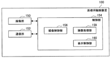
医療用観察装置100は、例えば、撮像部150と、通信部152と、制御部154とを備える。
The
撮像部150は、観察対象を撮像する。撮像部150は、例えば、“撮像デバイス106”(図1に示す医療用観察装置100の場合)や、“挿入部材134、光源ユニット136、およびカメラヘッド140”
(図7に示す医療用観察装置100の場合)で構成される。撮像部150における撮像は、例えば制御部154によって制御される。
The
(In the case of the
通信部152は、医療用観察装置100が備える通信手段であり、表示装置200などの外部装置と無線または有線で通信を行う役目を果たす。通信部152は、例えば上述した通信デバイス(図示せず)で構成される。通信部152における通信は、例えば制御部154によって制御される。
The
制御部154は、例えば上述したプロセッサ(図示せず)で構成され、医療用観察装置100全体を制御する役目を果たす。また、制御部154は、後述する画像処理方法に係る処理を主導的に行う役目を果たす。なお、制御部154における画像処理方法に係る処理は、複数の処理回路(例えば、複数のプロセッサなど)で分散して行われてもよい。
The
より具体的には、制御部154は、例えば、撮像制御部156と、画像処理部158と、表示制御部160とを有する。
More specifically, the
撮像制御部156は、撮像部150を構成する撮像デバイスを制御する。撮像デバイスの制御としては、例えば、少なくともズーム機能(光学ズーム機能および電子ズーム機能)を含む、AF機能の制御などの一般的に電子撮像式の顕微鏡部に備えられる1または2以上の機能の制御が、挙げられる。
The
画像処理部158は、後述する画像処理方法に係る処理を行い、医療用撮像画像を、画像処理方法に係る処理の対象となる表示装置200(以下、「対象の表示装置」と示す。)に対応するように処理する。対象の表示装置は、予め設定される固定の表示装置200であってもよいし、医療用観察装置100を用いる使用者の操作などによって任意に設定されてもよい。本実施形態に係る画像処理方法に係る処理の一例については、後述する。
The
表示制御部160は、例えば、表示制御信号と画像信号とを通信部152を構成する通信デバイス(図示せず)に伝達し、表示制御信号と画像信号とを表示装置200に対して送信させることによって、表示装置200における表示を制御する。表示制御部160が送信させる画像信号には、画像処理部158において画像処理方法に係る処理が行われた後の画像信号が含まれうる。なお、通信部152における通信の制御は、制御部154を構成する通信制御部(図示せず)により行われてもよい。
For example, the
制御部154は、例えば、画像処理部158を有することにより、本実施形態に係る画像処理方法に係る処理を主導的に行う役目を果たす。また、制御部154は、例えば、撮像制御部156、および表示制御部160を有することによって、医療用観察装置100全体を制御する役目を果たす。
The
なお、制御部154の機能構成は、図8に示す例に限られない。
The functional configuration of the
例えば、制御部154は、本実施形態に係る画像処理方法に係る処理の切り分け方に応じた構成など、医療用観察装置100が有する機能の切り分け方に応じた、任意の構成を有することが可能である。
For example, the
一例を挙げると、医療用観察装置100が図1に示す構成である場合、制御部154は、アーム104の駆動を制御するアーム制御部(図示せず)をさらに有していてもよい。アーム104の駆動の制御の一例としては、例えば、“関節部110a、110b、110c、110d、110e、110fそれぞれに対応するアクチュエータ(図示せず)に対して、駆動を制御する制御信号を印加すること”などが挙げられる。
For example, when the
医療用観察装置100は、例えば図8に示す機能構成によって、後述する本実施形態に係る画像処理方法に係る処理を行う。
The
なお、本実施形態に係る医療用観察装置の機能構成は、図8に示す構成に限られない。 Note that the functional configuration of the medical observation apparatus according to the present embodiment is not limited to the configuration illustrated in FIG.
例えば、本実施形態に係る医療用観察装置は、図8に示す撮像制御部156、画像処理部158、および表示制御部160のうちの一部または全部を、制御部154とは個別に備える(例えば、別の処理回路で実現する)ことができる。
For example, the medical observation apparatus according to the present embodiment includes a part or all of the
また、本実施形態に係る医療用観察装置において本実施形態に係る画像処理方法に係る処理を実行することが可能な機能構成は、図8に示す構成に限られず、例えば、本実施形態に係る医療用観察装置は、本実施形態に係る画像処理方法に係る処理の切り分け方に応じた機能構成をとることが可能である。 In addition, the functional configuration capable of executing the process according to the image processing method according to the present embodiment in the medical observation apparatus according to the present embodiment is not limited to the configuration illustrated in FIG. 8, for example, according to the present embodiment. The medical observation apparatus can have a functional configuration according to how to separate processes according to the image processing method according to the present embodiment.
また、本実施形態に係る医療用観察装置が図1に示す構成である場合、本実施形態に係る医療用観察装置は、アーム104で構成されるアーム部(図示せず)を有する。アーム部(図示せず)を構成するアーム104は、撮像部150を構成する撮像デバイス106を支持する。
In addition, when the medical observation apparatus according to the present embodiment has the configuration illustrated in FIG. 1, the medical observation apparatus according to the present embodiment includes an arm portion (not illustrated) configured by the
また、例えば、通信部152と同様の機能、構成を有する外部の通信デバイスを介して外部装置と通信を行う場合には、本実施形態に係る医療用観察装置は、通信部152を備えていなくてもよい。
In addition, for example, when communication with an external apparatus is performed via an external communication device having the same function and configuration as the
また、本実施形態に係る医療用観察システムが、医療用制御装置(図示せず)を有する構成であり、本実施形態に係る医療用観察装置が当該医療用制御装置(図示せず)により制御される場合、本実施形態に係る医療用観察装置は、制御部154を備えていなくてもよい。
Further, the medical observation system according to the present embodiment has a configuration having a medical control device (not shown), and the medical observation device according to the present embodiment is controlled by the medical control device (not shown). In this case, the medical observation apparatus according to this embodiment may not include the
ここで、医療用制御装置(図示せず)は、例えば、制御部154と同様の機能、構成を有する制御部を備えることによって、後述する本実施形態に係る画像処理方法に係る処理を行い、また、本実施形態に係る医療用観察装置が備える撮像部150などの各構成要素における動作を制御する。医療用制御装置(図示せず)は、備えている通信デバイス、または、接続されている外部の通信デバイスを介して、本実施形態に係る医療用観察装置と通信を行うことによって、本実施形態に係る医療用観察装置が備える各構成要素における動作を制御する。
Here, the medical control device (not shown) includes, for example, a control unit having the same function and configuration as the
さらに、本実施形態に係る医療用観察システムが、医療用制御装置(図示せず)を有する構成であり、本実施形態に係る医療用観察装置が当該医療用制御装置(図示せず)により制御される場合、本実施形態に係る医療用観察装置は、制御部154の一部の機能を有さない構成をとることも可能である。
Furthermore, the medical observation system according to the present embodiment has a configuration having a medical control device (not shown), and the medical observation device according to the present embodiment is controlled by the medical control device (not shown). In this case, the medical observation apparatus according to the present embodiment can have a configuration that does not have some functions of the
[2]本実施形態に係る画像処理方法
次に、本実施形態に係る画像処理方法について、説明する。以下では、本実施形態に係る画像処理方法に係る処理を医療用観察装置100(より具体的には、例えば医療用観察装置100を構成する制御部154)が行う場合を例に挙げる。なお、上述したように、本実施形態に係る医療用観察システムにおいて、本実施形態に係る画像処理方法に係る処理は、表示装置200や、医療用制御装置(図示せず)などにより行われてもよい。
[2] Image Processing Method According to this Embodiment Next, an image processing method according to this embodiment will be described. Hereinafter, a case where the medical observation apparatus 100 (more specifically, for example, the
[2−1]本実施形態に係る画像処理方法の概要
上述したように、医療用観察装置が用いられる手術では、1つの撮像デバイスで撮像された医療用撮像画像が、複数の術者それぞれに対応する表示装置の表示画面に表示され、各術者は、対応する表示画面を見て手技を行う場合がある。しかしながら、上記の場合、一部の術者について、表示画面内の天地方向が術者の向いている方向とズレてしまい、その結果、直感的な手技が妨げられることがあった。また、医療用観察装置を用いて直感的な手技を行うことができないことは、例えば医療用観察装置を用いる医療従事者の利便性の低下へと繋がりうる。
[2-1] Overview of Image Processing Method According to Present Embodiment As described above, in a surgery in which a medical observation apparatus is used, a medical captured image captured by one imaging device is transmitted to each of a plurality of operators. Each surgeon may perform a procedure while viewing the corresponding display screen, which is displayed on the display screen of the corresponding display device. However, in the above case, for some surgeons, the top-and-bottom direction in the display screen deviates from the direction in which the surgeon is facing, and as a result, intuitive techniques may be hindered. In addition, the inability to perform an intuitive procedure using a medical observation apparatus can lead to a decrease in convenience of a medical worker using the medical observation apparatus, for example.
そこで、医療用観察装置100は、医療用撮像画像を対象の表示装置に対応するように処理し、対象の表示装置に対応する医療用撮像画像を回転させる。対象の表示装置に対応する医療用撮像画像とは、対象の表示装置の表示画面に表示される医療用撮像画像(または、対象の表示装置の表示画面に表示するための医療用撮像画像)である。対象の表示装置の表示画面への医療用撮像画像の表示制御は、医療用観察装置100が行ってもよいし、表示装置200や医療用制御装置(図示せず)などにより行われてもよい。
Therefore, the
対象の表示装置に対応する医療用撮像画像が回転されることによって、表示画面内の天地方向と術者の向いている方向とを合わせることが可能となるので、上記のような“表示画面内の天地方向が術者の向いている方向とズレること”を防止することができる。 By rotating the medical image corresponding to the target display device, it is possible to match the vertical direction in the display screen with the direction in which the surgeon is facing. It is possible to prevent the top and bottom direction from deviating from the direction the surgeon is facing.
よって、本実施形態に係る画像処理方法が用いられることによって、医療従事者の利便性の向上を図ることができる。また、本実施形態に係る画像処理方法が用いられる場合、医療従事者による直感的な手技が妨げられることが防止されるので、例えば、手術効率の向上、より安全な手術の実現などに寄与することができる。 Therefore, by using the image processing method according to the present embodiment, it is possible to improve the convenience of medical staff. In addition, when the image processing method according to the present embodiment is used, it is possible to prevent an intuitive procedure by a medical worker from being hindered. For example, this contributes to an improvement in surgical efficiency and a safer operation. be able to.
図9は、本実施形態に係る画像処理方法の概要を説明するための説明図である。図9は、図3に示すように表示装置200A、200Bが配置されている場合において、表示装置200A、200Bそれぞれの表示画面に表示される医療用撮像画像の一例を示している。図9のAは、図3に示す表示装置200Aの表示画面に表示される医療用撮像画像の一例を示している。図9のBは、本実施形態に係る画像処理方法に係る処理により医療用撮像画像が回転されない場合に、図3に示す表示装置200Bの表示画面に表示される医療用撮像画像の一例を示している。図9のCは、本実施形態に係る画像処理方法に係る処理により医療用撮像画像が回転された場合に、図3に示す表示装置200Bの表示画面に表示される医療用撮像画像の一例を示している。
FIG. 9 is an explanatory diagram for explaining the outline of the image processing method according to the present embodiment. FIG. 9 shows an example of medical captured images displayed on the display screens of the
図3に示す第1術者の位置では、撮像デバイスの天地と第1術者の向いている方向と、表示装置200Aの配置方向とが揃っている。この場合、医療用観察装置100は、表示装置200Aに対応する医療用撮像画像を回転させない。よって、図9のAに示すように、第1術者の正面に配置されている表示装置200Aの表示画面の下側には第1術者自身の手が写ることとなり、第1術者は、違和感なく手技を行うことができる。
At the position of the first operator shown in FIG. 3, the orientation of the imaging device and the direction of the first operator are aligned with the arrangement direction of the
図3に示す第2術者の位置では、撮像デバイスの天地と第2術者の向いている方向と、表示装置200Bの配置方向とが揃っていない。よって、表示装置200Bに医療用撮像画像をそのまま表示させた場合には、図9のBに示すように、第2術者の正面に配置されている表示装置200Bの表示画面の下側には第2術者自身の手が写らず、表示画面内の天地方向が第2術者の向いている方向とズレてしまう。そのため、第2術者は、直感的に手技を行うことができない可能性がある。
In the position of the second operator shown in FIG. 3, the orientation of the imaging device and the direction of the second operator are not aligned with the arrangement direction of the
一方、医療用観察装置100が、対象の表示装置を表示装置200Bとして、表示装置200Bに対応する医療用撮像画像を回転させることによって、図9のCに示すように、第2術者の正面に配置されている表示装置200Bの表示画面の下側には第2術者自身の手が写ることとなる、この場合、第2術者は、違和感なく手技を行うことができる。
On the other hand, the
図10は、本実施形態に係る画像処理方法の概要を説明するための説明図である。図10は、図5に示すように表示装置200A、200B、200Cが配置されている場合において、表示装置200A、200B、200Cそれぞれの表示画面に表示される医療用撮像画像の一例を示している。図10のAは、図5に示す表示装置200Aの表示画面に表示される医療用撮像画像の一例を示している。図10のBは、本実施形態に係る画像処理方法に係る処理により医療用撮像画像が回転された場合に、図5に示す表示装置200Bの表示画面に表示される医療用撮像画像の一例を示している。図10のCは、本実施形態に係る画像処理方法に係る処理により医療用撮像画像が回転された場合に、図5に示す表示装置200Cの表示画面に表示される医療用撮像画像の一例を示している。図10に示す符号dは、撮像デバイスの天地方向、すなわち、当該撮像デバイスにより撮像された医療用撮像画像の向きを示している。
FIG. 10 is an explanatory diagram for explaining the outline of the image processing method according to the present embodiment. FIG. 10 illustrates an example of medical captured images displayed on the display screens of the
上述したように、図5に示す表示装置200A、200Bの配置関係と、図3に示す表示装置200A、200Bの配置関係とは、同一である。よって、医療用観察装置100は、図9のA、図9のCを参照して説明したように、表示装置200Aに対応する医療用撮像画像を回転させず、表示装置200Bに対応する医療用撮像画像を回転させる。よって、表示装置200A、200Bそれぞれの表示画面内の天地方向と、表示装置200A、200Bそれぞれを見る術者の向いている方向とを合わせることが、できる。
As described above, the arrangement relationship between the
また、上述したように、図5に示す例では、表示装置200Aと表示装置200Cとがなす角度が180[°]に設定される。よって、対象の表示装置を表示装置200Cとする場合、医療用観察装置100は、図10のCに示すように、表示装置200Cに対応する医療用撮像画像を、図10のAに示す医療用撮像画像を基準として180[°]回転させる。よって、表示装置200Cの表示画面内の天地方向と、表示装置200Cを見る医療従事者の向いている方向とを合わせることが、できる。
Further, as described above, in the example illustrated in FIG. 5, the angle formed by the display device 200 </ b> A and the display device 200 </ b> C is set to 180 [°]. Therefore, when the target display device is the display device 200C, the
なお、図10では、図10のB、図10のCに示すように、医療用撮像画像が反時計回りに90[°]回転する例(または、医療用撮像画像が時計回りに270[°]回転する例。図10のB)と、医療用撮像画像が反時計回りに180[°]回転する例(または、医療用撮像画像が時計回りに180[°]回転する例。図10のC)とを示している。しかしながら、医療用観察装置100が医療用撮像画像を回転させる角度は、図10に示す例に限られない。
In FIG. 10, as shown in FIG. 10B and FIG. 10C, an example in which the medical image is rotated 90 ° counterclockwise (or the medical image is 270 ° clockwise. 10B) and an example in which the medical image is rotated 180 [deg.] Counterclockwise (or an example in which the medical image is rotated 180 [°] clockwise. C). However, the angle at which the
例えば、医療用観察装置100は、本実施形態に係る角度センサにより検出された角度に応じて、医療用撮像画像を反時計回りまたは時計回りに回転させることが可能である。一例を挙げると、アブソリュート形のロータリエンコーダ(本実施形態に係る角度センサの一例。以下、同様とする。)により検出された角度が40[°]である場合、医療用観察装置100は、医療用撮像画像を反時計回りに40[°]回転させる。また、他の例を挙げると、アブソリュート形のロータリエンコーダにより検出された角度が80[°]である場合、医療用観察装置100は、医療用撮像画像を反時計回りに80[°]回転させる。なお、上記では、本実施形態に係る角度センサがアブソリュート形のロータリエンコーダである場合を例示したが、上述したように、本実施形態に係る角度センサは、インクリメンタル形のロータリエンコーダや、撮像デバイスなどであってもよい。
For example, the
[2−2]本実施形態に係る画像処理方法に係る処理
次に、本実施形態に係る画像処理方法に係る処理について、より具体的に説明する。
[2-2] Processing According to Image Processing Method According to This Embodiment Next, processing according to the image processing method according to this embodiment will be described more specifically.
医療用観察装置100は、医療用観察装置100は、医療用撮像画像を対象の表示装置に対応するように処理して、対象の表示装置に対応する医療用撮像画像を回転させる。
The
より具体的には、医療用観察装置100は、設定される主表示装置に対する対象の表示装置の相対的な配置関係に基づいて、医療用撮像画像を回転させる。対象の表示装置が複数存在する場合、医療用観察装置100は、対象の表示装置ごとに、主表示装置に対する相対的な配置関係に基づいて、対象の表示装置に対応する医療用撮像画像を回転させる。
More specifically, the
本実施形態に係る主表示装置とは、表示装置200の相対的な配置関係の基準となる表示装置200である。主表示装置は、予め設定されている固定の表示装置200であってもよいし、医療用観察システム1000を用いる使用者の操作などによって任意に設定されてもよい。図9、図10参照して説明した例は、表示装置200Aが主表示装置として設定されている例である。
The main display device according to the present embodiment is the display device 200 that serves as a reference for the relative arrangement relationship of the display device 200. The main display device may be a fixed display device 200 set in advance, or may be arbitrarily set by a user's operation using the
図2〜図5を参照して示したように、表示装置200間の相対的な角度によって、表示装置200間の相対的な配置関係を特定することが可能である。よって、医療用観察装置100は、主表示装置に対する対象の表示装置の相対的な角度に対応するように、対象の表示装置に対応する医療用撮像画像を回転させることによって、主表示装置に対する対象の表示装置の相対的な配置関係に基づく医療用撮像画像の回転を、実現する。
As shown with reference to FIGS. 2 to 5, the relative arrangement relationship between the display devices 200 can be specified by the relative angle between the display devices 200. Therefore, the
具体例として、図3に示すように表示装置200A、200Bが配置され、表示装置200Aが主表示装置である場合を例に挙げる。
As a specific example, a case where the
例えば、表示装置200Aと表示装置200Bとの相対的な配置関係の基準が上記第1の配置関係である場合、表示装置200A、200B間の相対的な角度である角度aは、(反時計回り方向を正とすると)90[°]である。この場合、表示装置200Bを対象の表示装置としたとき、医療用観察装置100は、表示装置200Bに対応する医療用撮像画像を、180−a=90[°]回転させる。
For example, when the reference of the relative arrangement relationship between the
また、例えば、表示装置200Aと表示装置200Bとの相対的な配置関係の基準が上記第2の配置関係である場合、表示装置200A、200B間の相対的な角度である角度bは、(反時計回り方向を正とすると)−90[°]である。この場合、表示装置200Bを対象の表示装置としたとき、医療用観察装置100は、表示装置200Bに対応する医療用撮像画像を、−b=90[°]回転させる。
For example, when the reference of the relative arrangement relationship between the
よって、表示装置200Bの表示画面には、例えば図9のCに示すように回転された医療用撮像画像が表示される。なお、上述したように、医療用観察装置100は、本実施形態に係る角度センサにより検出された角度に応じて、医療用撮像画像を反時計回りまたは時計回りに回転させることが可能である。つまり、医療用観察装置100が医療用撮像画像を回転させる回転角度は、図3を参照して説明した例に限られない。
Therefore, the medical captured image rotated as shown in FIG. 9C is displayed on the display screen of the
なお、“主表示装置に対する対象の表示装置の相対的な角度に対応するように、対象の表示装置に対応する医療用撮像画像を回転させる処理”は、上記に示す例に限られない。 Note that “the process of rotating the medical captured image corresponding to the target display device so as to correspond to the relative angle of the target display device with respect to the main display device” is not limited to the example described above.
例えば、医療用観察装置100は、本実施形態に係る角度センサにより検出された角度に応じて、医療用撮像画像を不連続に回転させることも可能である。表示装置200Aと表示装置200Bとの相対的な配置関係の基準が上記第2の配置関係であるときにおいて、不連続に回転させる場合の一例を挙げると、医療用観察装置100は、主表示装置に対する対象の表示装置の相対的な角度に応じて下記のように医療用撮像画像を回転させる。なお、不連続に医療用撮像画像を回転させる場合の例が、下記に示す例に限られないことは、言うまでもない。
・主表示装置に対する対象の表示装置の相対的な角度が271[°]〜45[°]の場合:医療用撮像画像を回転させない
・主表示装置に対する対象の表示装置の相対的な角度が46[°]〜135[°]の場合:医療用撮像画像を−90[°]回転させる
・主表示装置に対する対象の表示装置の相対的な角度が136[°]〜225[°]の場合:医療用撮像画像を−180[°]回転させる
・主表示装置に対する対象の表示装置の相対的な角度が226[°]〜270[°]の場合:医療用撮像画像を−270[°]回転させる
For example, the
When the relative angle of the target display device with respect to the main display device is 271 [°] to 45 [°]: The medical captured image is not rotated. The relative angle of the target display device with respect to the main display device is 46. In the case of [°] to 135 [°]: The medical captured image is rotated by −90 [°]. When the relative angle of the target display device with respect to the main display device is 136 [°] to 225 [°]: Rotate medical captured image by −180 [°] When the relative angle of the target display device with respect to the main display device is 226 [°] to 270 [°]: rotate the medical captured image by −270 [°] Make
上記では、表示装置200Aと表示装置200Bとの相対的な配置関係の基準が、上記第1の配置関係である場合または上記第2の配置関係である場合を例に挙げたが、医療用観察装置100は、基準の取り方、および回転の仕方に関係なく、表示装置200の相対的な配置関係に基づき医療用撮像画像を回転させる。
In the above description, the case where the reference of the relative arrangement relationship between the
主表示装置として設定されている表示装置200が、対象の表示装置として設定されている場合、医療用観察装置100は、主表示装置に対応する医療用撮像画像を回転させない。
When the display device 200 set as the main display device is set as the target display device, the
例えば、医療用観察装置100は、主表示装置として設定されている表示装置200に対して、表示装置200間の相対的な角度に基づく回転処理を行わないことによって、主表示装置に対応する医療用撮像画像を回転させない。
For example, the
また、主表示装置として設定されている表示装置200が対象の表示装置として設定されている場合、医療用観察装置100は、表示装置200間の相対的な角度に基づく回転処理を行ってもよい。この場合、主表示装置と対象の表示装置とは同一の表示装置200であるので、主表示装置と対象の表示装置との相対的な角度は0[°]となる。よって、表示装置200間の相対的な角度に基づく回転処理を行う場合であっても、主表示装置に対応する医療用撮像画像は回転されないこととなる。
When the display device 200 set as the main display device is set as the target display device, the
なお、医療用観察装置100は、主表示装置に対応する医療用撮像画像を、主表示装置と主表示装置に対応付けられている医療従事者との位置関係によって回転させてもよい。主表示装置と主表示装置に対応付けられている医療従事者との位置関係は、例えば、医療従事者が装着している位置センサを用いる方法や、術場カメラなどの撮像デバイスにより撮像された撮像画像を解析する方法など、位置関係を特定することが可能な任意の方法によって、特定される。
Note that the
例えば、上記のように“主表示装置と主表示装置に対応付けられている医療従事者との位置関係によって、主表示装置に対応する医療用撮像画像が回転される場合”、医療用観察装置100は、主表示装置に対応する医療用撮像画像の回転分、他の対象の表示装置に対応する医療用撮像画像をさらに回転させる。
For example, as described above, “when the medical imaging image corresponding to the main display device is rotated by the positional relationship between the main display device and the medical staff associated with the main display device”, the
なお、本実施形態に係る画像処理方法に係る処理は、上記に示す例に限られない。 Note that the processing related to the image processing method according to the present embodiment is not limited to the example shown above.
例えば、医療用観察装置100は、所定の操作に基づいて、医療用撮像画像を対象の表示装置に対応するように処理する機能を有効化し、または当該機能を無効化してもよい。つまり、医療用観察装置100は、対象の表示装置に対応する医療用撮像画像を回転させる処理を行うか否かを、選択的に切り替えることが可能であってもよい。
For example, the
本実施形態に係る所定の操作としては、例えば、医療用観察装置100が備える操作デバイスに対する上記機能の切り替え操作、リモートコントローラやフットスイッチなどの外部の操作デバイスに対する上記機能の切り替え操作などが、挙げられる。
Examples of the predetermined operation according to the present embodiment include a switching operation of the above function with respect to an operation device included in the
医療用観察装置100は、例えば、上記機能の切り替え操作に応じた切替信号に応じて、上記機能を有効化して対象の表示装置に対応する医療用撮像画像を回転させる処理を行い、または上記機能を無効化して対象の表示装置に対応する医療用撮像画像を回転させる処理を行わない。本実施形態に係る切替信号としては、例えば、機能の有効化、無効化を信号レベルで表す信号(例えば、ハイレベルの切替信号が機能の有効化を示し、ローレベルの切替信号が機能の無効化を示す。)が挙げられる。なお、本実施形態に係る切替信号が、上記に示す例に限られないことは、言うまでもない。
The
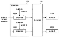
図11は、本実施形態に係る画像処理方法に係る処理の一例を説明するための説明図であり、対象の表示装置が表示装置200A、200Bである場合における画像処理方法に係る処理の一例を、図8に示す機能ブロックを用いて表している。図11では、図8に示す画像処理部158と表示制御部160を示すと共に、対象の表示装置の一例として、表示装置200A、200Bを併せて示している。
FIG. 11 is an explanatory diagram for explaining an example of processing related to the image processing method according to the present embodiment, and an example of processing related to the image processing method when the target display devices are the
図11に示す画像処理部158は、表示装置200Aに対応する回転処理部162Aと、表示装置200Bに対応する回転処理部162Bとを有する。つまり、図11に示す画像処理部158は、対象の表示装置それぞれに対応する回転処理部を有する。
The
回転処理部162Aは、主表示装置に対する表示装置200Aの相対的な角度を示す角度情報Aに基づいて、画像信号が示す医療用撮像画像を回転させる。回転処理部162Aは、例えば、角度情報Aが示す角度分、医療用撮像画像を回転させる。
The
上述したように、表示装置200Aが主表示装置である場合には、回転処理部162Aは、医療用撮像画像を回転させない。また上述したように、主表示装置に対応する医療用撮像画像が回転される場合には、回転処理部162Aは、主表示装置に対応する医療用撮像画像の回転分、医療用撮像画像をさらに回転させる。
As described above, when the
また、切替信号が伝達される場合、回転処理部162Aは、例えば、切替信号に応じて医療用撮像画像を回転させる処理を行う動作モードを設定し、または、切替信号に応じて医療用撮像画像を回転させる処理を行わない動作モードを設定する。そして、設定される動作モードに従って、医療用撮像画像を回転させる処理を選択的に行う。
In addition, when the switching signal is transmitted, the
回転処理部162Aは、処理後の医療用撮像画像を示す画像信号を表示制御部160へ伝達する。そして、表示制御部160は、回転処理部162Aから伝達される画像信号が示す医療用撮像画像を、表示装置200Aの表示画面に表示させる。
The
なお、図11では、回転処理部162Aに1つの画像信号が入力される例を示しているが、回転処理部162Aには、右目用の医療用撮像画像を示す画像信号と、左目用の医療用撮像画像を示す画像信号とが入力されてもよい。この場合、回転処理部162Aは、右目用の医療用撮像画像を示す画像信号、および左目用の医療用撮像画像を示す画像信号それぞれに対して、図11を参照して説明した処理を行う。
FIG. 11 shows an example in which one image signal is input to the
回転処理部162Bは、主表示装置に対する表示装置200Bの相対的な角度を示す角度情報Bに基づいて、画像信号が示す医療用撮像画像を回転させる。回転処理部162Bは、例えば、角度情報Bが示す角度分、医療用撮像画像を回転させる。
The
表示装置200Bが主表示装置である場合、回転処理部162Bは、回転処理部162Aと同様に、医療用撮像画像を回転させない。また、回転処理部162Aと同様に、主表示装置に対応する医療用撮像画像が回転される場合には、回転処理部162Bは、主表示装置に対応する医療用撮像画像の回転分、医療用撮像画像をさらに回転させる。
When the
また、切替信号が伝達される場合、回転処理部162Bは、回転処理部162Aと同様に、切替信号に応じて設定される動作モードに従って、医療用撮像画像を回転させる処理を選択的に行う。
When the switching signal is transmitted, the
回転処理部162Bは、処理後の医療用撮像画像を示す画像信号を表示制御部160へ伝達する。そして、表示制御部160は、回転処理部162Bから伝達される画像信号が示す医療用撮像画像を、表示装置200Bの表示画面に表示させる。
The
なお、図11では、回転処理部162Bに1つの画像信号が入力される例を示しているが、回転処理部162Bには、右目用の医療用撮像画像を示す画像信号と、左目用の医療用撮像画像を示す画像信号とが入力されてもよい。この場合、回転処理部162Bは、右目用の医療用撮像画像を示す画像信号、および左目用の医療用撮像画像を示す画像信号それぞれに対して、図11を参照して説明した処理を行う。
FIG. 11 illustrates an example in which one image signal is input to the
例えば図11に示すように、画像処理部158は、対象の表示装置それぞれに対応する回転処理部を有することによって、対象の表示装置ごとに、相対的な配置関係に基づき医療用撮像画像を回転させる。なお、画像処理部158の機能構成が、図11に示す例に限られないことは、言うまでもない。
For example, as illustrated in FIG. 11, the
[3]本実施形態に係る画像処理方法が用いられることにより奏される効果の一例
本実施形態に係る画像処理方法が用いられることによって、例えば下記に示す効果が奏される。なお、本実施形態に係る画像処理方法が用いられることにより奏される効果が、下記に示す例に限られないことは、言うまでもない。
・本実施形態に係る画像処理方法が用いられることにより、表示画面内の天地方向と術者の向いている方向とを合わせることが可能となるので、図3に示すような表示装置200の配置であっても、第1術者と共に、第2術者も正しい向きの医療用撮像画像を見ることができる。
・正しい向きの医療用撮像画像を見ることができるので、術者は直感的に手技を行うことができる。
・仮に、術中に表示装置200の配置がかわった場合であっても、本実施形態に係る画像処理方法に係る処理により医療用撮像画像が回転するので、術者は直感的に手技を継続して行うことができる。また、この場合、特段の設定変更などは不要であるので、設定変更などを行うための時間は不要であり、手術時間の短縮に寄与しうる。
[3] An example of an effect produced by using the image processing method according to the present embodiment The following effects can be obtained by using the image processing method according to the present embodiment, for example. Needless to say, the effects produced by using the image processing method according to the present embodiment are not limited to the examples shown below.
Since the image processing method according to the present embodiment is used, it is possible to match the vertical direction in the display screen with the direction in which the operator is facing, so the arrangement of the display device 200 as shown in FIG. Even so, together with the first operator, the second operator can also view the medical image of the correct orientation.
-Since the medical image can be viewed in the correct orientation, the surgeon can intuitively perform the procedure.
Even if the arrangement of the display device 200 is changed during the operation, the medical image is rotated by the process according to the image processing method according to the present embodiment, so that the surgeon continues the technique intuitively. Can be done. In this case, since no special setting change or the like is necessary, time for performing the setting change or the like is unnecessary, which can contribute to shortening of the operation time.
(本実施形態に係るプログラム)
コンピュータシステムを、本実施形態に係る医療用観察装置(または、本実施形態に係る医療用画像処理装置)として機能させるためのプログラム(例えば、本実施形態に係る画像処理方法に係る処理を実行することが可能なプログラム)が、コンピュータシステムにおいてプロセッサなどにより実行されることによって、医療従事者の利便性の向上を図ることができる。ここで、本実施形態に係るコンピュータシステムとしては、単体のコンピュータ、または、複数のコンピュータが挙げられる。本実施形態に係るコンピュータシステムによって、本実施形態に係る画像処理方法に係る一連の処理が行われる。
(Program according to this embodiment)
A program for causing a computer system to function as the medical observation apparatus according to the present embodiment (or the medical image processing apparatus according to the present embodiment) (for example, processing related to the image processing method according to the present embodiment) Program) that is executed by a processor or the like in the computer system, the convenience of the medical staff can be improved. Here, the computer system according to the present embodiment includes a single computer or a plurality of computers. A series of processing relating to the image processing method according to the present embodiment is performed by the computer system according to the present embodiment.
また、コンピュータシステムを、本実施形態に係る医療用観察装置(または、本実施形態に係る医療用画像処理装置)として機能させるためのプログラムが、コンピュータシステムにおいてプロセッサなどにより実行されることによって、上述した本実施形態に係る画像処理方法に係る処理によって実現される表示によって奏される効果を、奏することができる。 In addition, a program for causing a computer system to function as the medical observation apparatus according to the present embodiment (or the medical image processing apparatus according to the present embodiment) is executed by a processor or the like in the computer system. The effect produced by the display realized by the process according to the image processing method according to the present embodiment can be achieved.
以上、添付図面を参照しながら本開示の好適な実施形態について詳細に説明したが、本開示の技術的範囲はかかる例に限定されない。本開示の技術分野における通常の知識を有する者であれば、特許請求の範囲に記載された技術的思想の範疇内において、各種の変更例または修正例に想到しうることは明らかであり、これらについても、当然に本開示の技術的範囲に属するものと了解される。 The preferred embodiments of the present disclosure have been described in detail above with reference to the accompanying drawings, but the technical scope of the present disclosure is not limited to such examples. It is obvious that those having ordinary knowledge in the technical field of the present disclosure can come up with various changes or modifications within the scope of the technical idea described in the claims. Of course, it is understood that it belongs to the technical scope of the present disclosure.
例えば、上記では、コンピュータシステムを、本実施形態に係る医療用観察装置(または、本実施形態に係る医療用画像処理装置)として機能させるためのプログラム(コンピュータプログラム)が提供されることを示したが、本実施形態は、さらに、上記プログラムを記憶させた記録媒体も、併せて提供することができる。 For example, in the above, it has been shown that a program (computer program) for causing a computer system to function as the medical observation apparatus according to the present embodiment (or the medical image processing apparatus according to the present embodiment) is provided. However, the present embodiment can also provide a recording medium storing the program.
上述した構成は、本実施形態の一例を示すものであり、当然に、本開示の技術的範囲に属するものである。 The configuration described above shows an example of the present embodiment, and naturally belongs to the technical scope of the present disclosure.
また、本明細書に記載された効果は、あくまで説明的または例示的なものであって限定的ではない。つまり、本開示に係る技術は、上記の効果とともに、または上記の効果に代えて、本明細書の記載から当業者には明らかな他の効果を奏しうる。 Further, the effects described in the present specification are merely illustrative or exemplary and are not limited. That is, the technology according to the present disclosure can exhibit other effects that are apparent to those skilled in the art from the description of the present specification in addition to or instead of the above effects.
なお、以下のような構成も本開示の技術的範囲に属する。
(1)
観察対象を撮像する撮像デバイスにより撮像された医療用撮像画像を、対象の表示装置に対応するように処理する機能を有する画像処理部を備え、
前記画像処理部は、設定される主表示装置に対する前記対象の表示装置の相対的な配置関係に基づいて、前記医療用撮像画像を回転させる、医療用画像処理装置。
(2)
前記対象の表示装置が複数存在する場合、前記画像処理部は、前記対象の表示装置ごとに、前記相対的な配置関係に基づいて前記医療用撮像画像を回転させる、(1)に記載の医療用画像処理装置。
(3)
前記対象の表示装置が前記主表示装置である場合、前記画像処理部は、前記医療用撮像画像を回転させない、(1)または(2)に記載の医療用画像処理装置。
(4)
前記画像処理部は、前記主表示装置に対する前記対象の表示装置の相対的な角度に対応するように、前記医療用撮像画像を回転させる、(1)〜(3)のいずれか1つに記載の医療用画像処理装置。
(5)
前記相対的な角度は、1または2以上の角度センサの検出結果に基づき特定される、(4)に記載の医療用画像処理装置。
(6)
前記画像処理部は、所定の操作に基づいて、前記機能を有効化し、または前記機能を無効化する、(1)〜(5)のいずれか1つに記載の医療用画像処理装置。
(7)
前記対象の表示装置の表示画面への前記医療用撮像画像の表示を制御する表示制御部をさらに備える、(1)〜(6)のいずれか1つに記載の医療用画像処理装置。
(8)
観察対象を撮像する撮像デバイスと、
前記撮像デバイスにより撮像された医療用撮像画像を、対象の表示装置に対応するように処理する機能を有する画像処理部と、
を備え、
前記画像処理部は、設定される主表示装置に対する前記対象の表示装置の相対的な配置関係に基づいて、前記医療用撮像画像を回転させる、医療用観察装置。
(9)
複数のリンクが関節部によって互いに連結されて構成されるアームをさらに備え、
前記撮像デバイスは、前記アームにより支持される、(8)に記載の医療用観察装置。
(10)
前記撮像デバイスは、患者の体内に挿入され、前記体内を前記観察対象として撮像する、(8)に記載の医療用観察装置。
(11)
観察対象を撮像する撮像デバイスにより撮像された医療用撮像画像を、対象の表示装置に対応するように処理するステップを有し、
前記処理するステップでは、設定される主表示装置に対する前記対象の表示装置の相対的な配置関係に基づいて、前記医療用撮像画像が回転される、医療用画像処理装置により実行される画像処理方法。
The following configurations also belong to the technical scope of the present disclosure.
(1)
An image processing unit having a function of processing a medical captured image captured by an imaging device that captures an observation target so as to correspond to the target display device;
The said image processing part is a medical image processing apparatus which rotates the said medical picked-up image based on the relative arrangement | positioning relationship of the said target display apparatus with respect to the main display apparatus set.
(2)
The medical treatment according to (1), wherein when there are a plurality of target display devices, the image processing unit rotates the medical captured image for each target display device based on the relative arrangement relationship. Image processing device.
(3)
The medical image processing apparatus according to (1) or (2), wherein when the target display device is the main display device, the image processing unit does not rotate the medical captured image.
(4)
The image processing unit rotates the medical captured image so as to correspond to a relative angle of the target display device with respect to the main display device, according to any one of (1) to (3). Medical image processing device.
(5)
The medical image processing apparatus according to (4), wherein the relative angle is specified based on a detection result of one or more angle sensors.
(6)
The medical image processing apparatus according to any one of (1) to (5), wherein the image processing unit validates the function or invalidates the function based on a predetermined operation.
(7)
The medical image processing apparatus according to any one of (1) to (6), further including a display control unit that controls display of the medical captured image on a display screen of the target display device.
(8)
An imaging device for imaging an observation target;
An image processing unit having a function of processing a medical captured image captured by the imaging device so as to correspond to a target display device;
With
The medical processing device, wherein the image processing unit rotates the medical captured image based on a relative arrangement relationship of the target display device with respect to a set main display device.
(9)
An arm configured by connecting a plurality of links to each other by joints;
The medical observation apparatus according to (8), wherein the imaging device is supported by the arm.
(10)
The medical observation apparatus according to (8), wherein the imaging device is inserted into a patient's body and images the body as the observation target.
(11)
Processing a medical captured image captured by an imaging device that captures an observation target so as to correspond to the target display device;
In the processing step, the medical image processing method is executed by the medical image processing device in which the medical captured image is rotated based on a relative arrangement relationship of the target display device with respect to the set main display device. .
100 医療用観察装置
102 ベース
104、A、A1、A2 アーム
106 撮像デバイス
110a、110b、110c、110d、110e、110f 関節部
112a、112b、112c、112d、112e、112f リンク
120 撮像部材
122 筒状部材
124 ズームスイッチ
126 フォーカススイッチ
128 動作モード変更スイッチ
134 挿入部材
136 光源ユニット
138 ライトガイド
140 カメラヘッド
142 ケーブル
144 制御ユニット
150 撮像部
152 通信部
154 制御部
156 撮像制御部
158 画像処理部
160 表示制御部
200、200A、200B、200C 表示装置
1000 医療用観察システム
S 角度センサ
DESCRIPTION OF
Claims (11)
前記画像処理部は、設定される主表示装置に対する前記対象の表示装置の相対的な配置関係に基づいて、前記医療用撮像画像を回転させる、医療用画像処理装置。 An image processing unit having a function of processing a medical captured image captured by an imaging device that captures an observation target so as to correspond to the target display device;
The said image processing part is a medical image processing apparatus which rotates the said medical picked-up image based on the relative arrangement | positioning relationship of the said target display apparatus with respect to the main display apparatus set.
前記撮像デバイスにより撮像された医療用撮像画像を、対象の表示装置に対応するように処理する機能を有する画像処理部と、
を備え、
前記画像処理部は、設定される主表示装置に対する前記対象の表示装置の相対的な配置関係に基づいて、前記医療用撮像画像を回転させる、医療用観察装置。 An imaging device for imaging an observation target;
An image processing unit having a function of processing a medical captured image captured by the imaging device so as to correspond to a target display device;
With
The medical processing device, wherein the image processing unit rotates the medical captured image based on a relative arrangement relationship of the target display device with respect to a set main display device.
前記撮像デバイスは、前記アームにより支持される、請求項8に記載の医療用観察装置。 An arm configured by connecting a plurality of links to each other by joints;
The medical observation apparatus according to claim 8, wherein the imaging device is supported by the arm.
前記処理するステップでは、設定される主表示装置に対する前記対象の表示装置の相対的な配置関係に基づいて、前記医療用撮像画像が回転される、医療用画像処理装置により実行される画像処理方法。
Processing a medical captured image captured by an imaging device that captures an observation target so as to correspond to the target display device;
In the processing step, the medical image processing method is executed by the medical image processing device in which the medical captured image is rotated based on a relative arrangement relationship of the target display device with respect to the set main display device. .
Priority Applications (2)
| Application Number | Priority Date | Filing Date | Title |
|---|---|---|---|
| JP2018047492A JP2019154883A (en) | 2018-03-15 | 2018-03-15 | Medical image processing apparatus, medical observation apparatus, and image processing method |
| US16/285,265 US20190282063A1 (en) | 2018-03-15 | 2019-02-26 | Medical image processing apparatus, medical observation apparatus, and image processing method |
Applications Claiming Priority (1)
| Application Number | Priority Date | Filing Date | Title |
|---|---|---|---|
| JP2018047492A JP2019154883A (en) | 2018-03-15 | 2018-03-15 | Medical image processing apparatus, medical observation apparatus, and image processing method |
Publications (2)
| Publication Number | Publication Date |
|---|---|
| JP2019154883A true JP2019154883A (en) | 2019-09-19 |
| JP2019154883A5 JP2019154883A5 (en) | 2021-04-22 |
Family
ID=67903647
Family Applications (1)
| Application Number | Title | Priority Date | Filing Date |
|---|---|---|---|
| JP2018047492A Pending JP2019154883A (en) | 2018-03-15 | 2018-03-15 | Medical image processing apparatus, medical observation apparatus, and image processing method |
Country Status (2)
| Country | Link |
|---|---|
| US (1) | US20190282063A1 (en) |
| JP (1) | JP2019154883A (en) |
Cited By (1)
| Publication number | Priority date | Publication date | Assignee | Title |
|---|---|---|---|---|
| WO2022064998A1 (en) * | 2020-09-23 | 2022-03-31 | 株式会社Aiメディカルサービス | Inspection assistance device, inspection assistance method, and inspection assistance program |
Families Citing this family (1)
| Publication number | Priority date | Publication date | Assignee | Title |
|---|---|---|---|---|
| CN112190348A (en) * | 2020-09-23 | 2021-01-08 | 苏州速迈医疗设备有限公司 | Double operating microscope |
Citations (5)
| Publication number | Priority date | Publication date | Assignee | Title |
|---|---|---|---|---|
| JPH07265264A (en) * | 1994-04-01 | 1995-10-17 | Olympus Optical Co Ltd | Image processing device |
| US20070010710A1 (en) * | 2005-07-09 | 2007-01-11 | Timothy Perez | Biological imaging systems |
| JP2014200547A (en) * | 2013-04-08 | 2014-10-27 | 学校法人同志社 | Endoscope system |
| WO2016208246A1 (en) * | 2015-06-24 | 2016-12-29 | ソニー・オリンパスメディカルソリューションズ株式会社 | Three-dimensional observation device for medical use, three-dimensional observation method for medical use, and program |
| WO2018025483A1 (en) * | 2016-08-03 | 2018-02-08 | シャープ株式会社 | Video outputting system, video outputting method, and control apparatus |
Family Cites Families (1)
| Publication number | Priority date | Publication date | Assignee | Title |
|---|---|---|---|---|
| EP2525736A4 (en) * | 2010-01-22 | 2013-08-21 | Prec Through Imaging Llc | Dental implantation system and method |
-
2018
- 2018-03-15 JP JP2018047492A patent/JP2019154883A/en active Pending
-
2019
- 2019-02-26 US US16/285,265 patent/US20190282063A1/en not_active Abandoned
Patent Citations (5)
| Publication number | Priority date | Publication date | Assignee | Title |
|---|---|---|---|---|
| JPH07265264A (en) * | 1994-04-01 | 1995-10-17 | Olympus Optical Co Ltd | Image processing device |
| US20070010710A1 (en) * | 2005-07-09 | 2007-01-11 | Timothy Perez | Biological imaging systems |
| JP2014200547A (en) * | 2013-04-08 | 2014-10-27 | 学校法人同志社 | Endoscope system |
| WO2016208246A1 (en) * | 2015-06-24 | 2016-12-29 | ソニー・オリンパスメディカルソリューションズ株式会社 | Three-dimensional observation device for medical use, three-dimensional observation method for medical use, and program |
| WO2018025483A1 (en) * | 2016-08-03 | 2018-02-08 | シャープ株式会社 | Video outputting system, video outputting method, and control apparatus |
Cited By (1)
| Publication number | Priority date | Publication date | Assignee | Title |
|---|---|---|---|---|
| WO2022064998A1 (en) * | 2020-09-23 | 2022-03-31 | 株式会社Aiメディカルサービス | Inspection assistance device, inspection assistance method, and inspection assistance program |
Also Published As
| Publication number | Publication date |
|---|---|
| US20190282063A1 (en) | 2019-09-19 |
Similar Documents
| Publication | Publication Date | Title |
|---|---|---|
| JP7208972B2 (en) | medical observation device | |
| JP2023099552A (en) | Medical observation system and medical control device | |
| WO2018216302A1 (en) | Medical observation apparatus, processing method, and medical observation system | |
| JP2023095970A (en) | medical observation system | |
| JP2019154883A (en) | Medical image processing apparatus, medical observation apparatus, and image processing method | |
| US10849484B2 (en) | Medical observation apparatus | |
| JP7109936B2 (en) | Medical control device and control method | |
| JP6957605B2 (en) | Medical observation system and control method | |
| JP6904762B2 (en) | Medical sterilization cover and medical observation device | |
| JP7134656B2 (en) | Medical display control device and display control method | |
| US11699516B2 (en) | Medical image processing apparatus, medical observation apparatus, and image processing method | |
| WO2019181212A1 (en) | Medical display control device and display control method | |
| JP7073145B2 (en) | How to operate the medical dimming control device and the medical dimming control device | |
| US11648082B2 (en) | Medical holding device, and medical observation device | |
| WO2019181239A1 (en) | Medical holding apparatus | |
| WO2019111482A1 (en) | Medical control apparatus and control method |
Legal Events
| Date | Code | Title | Description |
|---|---|---|---|
| RD04 | Notification of resignation of power of attorney |
Free format text: JAPANESE INTERMEDIATE CODE: A7424 Effective date: 20190208 |
|
| RD04 | Notification of resignation of power of attorney |
Free format text: JAPANESE INTERMEDIATE CODE: A7424 Effective date: 20190222 |
|
| RD02 | Notification of acceptance of power of attorney |
Free format text: JAPANESE INTERMEDIATE CODE: A7422 Effective date: 20190515 |
|
| RD04 | Notification of resignation of power of attorney |
Free format text: JAPANESE INTERMEDIATE CODE: A7424 Effective date: 20190522 |
|
| A521 | Request for written amendment filed |
Free format text: JAPANESE INTERMEDIATE CODE: A523 Effective date: 20210311 |
|
| A621 | Written request for application examination |
Free format text: JAPANESE INTERMEDIATE CODE: A621 Effective date: 20210311 |
|
| A977 | Report on retrieval |
Free format text: JAPANESE INTERMEDIATE CODE: A971007 Effective date: 20220228 |
|
| A131 | Notification of reasons for refusal |
Free format text: JAPANESE INTERMEDIATE CODE: A131 Effective date: 20220322 |
|
| A521 | Request for written amendment filed |
Free format text: JAPANESE INTERMEDIATE CODE: A523 Effective date: 20220519 |
|
| A02 | Decision of refusal |
Free format text: JAPANESE INTERMEDIATE CODE: A02 Effective date: 20220816 |