JP2019149259A - Separator for power storage device, manufacturing method thereof, integral structure for power storage device, and manufacturing method thereof - Google Patents
Separator for power storage device, manufacturing method thereof, integral structure for power storage device, and manufacturing method thereof Download PDFInfo
- Publication number
- JP2019149259A JP2019149259A JP2018032431A JP2018032431A JP2019149259A JP 2019149259 A JP2019149259 A JP 2019149259A JP 2018032431 A JP2018032431 A JP 2018032431A JP 2018032431 A JP2018032431 A JP 2018032431A JP 2019149259 A JP2019149259 A JP 2019149259A
- Authority
- JP
- Japan
- Prior art keywords
- separator
- negative electrode
- positive electrode
- active material
- dispersion
- Prior art date
- Legal status (The legal status is an assumption and is not a legal conclusion. Google has not performed a legal analysis and makes no representation as to the accuracy of the status listed.)
- Pending
Links
- 238000003860 storage Methods 0.000 title claims abstract description 35
- 238000004519 manufacturing process Methods 0.000 title claims abstract description 25
- 239000000835 fiber Substances 0.000 claims abstract description 109
- 239000006185 dispersion Substances 0.000 claims description 100
- 239000002904 solvent Substances 0.000 claims description 41
- OKTJSMMVPCPJKN-UHFFFAOYSA-N Carbon Chemical group [C] OKTJSMMVPCPJKN-UHFFFAOYSA-N 0.000 claims description 32
- 239000007773 negative electrode material Substances 0.000 claims description 30
- 239000007774 positive electrode material Substances 0.000 claims description 30
- 230000015572 biosynthetic process Effects 0.000 claims description 28
- 239000002041 carbon nanotube Substances 0.000 claims description 24
- 238000002360 preparation method Methods 0.000 claims description 24
- 230000005611 electricity Effects 0.000 claims description 22
- 229910021393 carbon nanotube Inorganic materials 0.000 claims description 20
- 238000000034 method Methods 0.000 claims description 15
- 239000007788 liquid Substances 0.000 claims description 13
- 230000008569 process Effects 0.000 claims description 10
- 229910052582 BN Inorganic materials 0.000 claims description 6
- PZNSFCLAULLKQX-UHFFFAOYSA-N Boron nitride Chemical group N#B PZNSFCLAULLKQX-UHFFFAOYSA-N 0.000 claims description 6
- 239000002121 nanofiber Substances 0.000 claims description 6
- 239000002071 nanotube Substances 0.000 claims description 6
- 239000004020 conductor Substances 0.000 claims 1
- 239000006183 anode active material Substances 0.000 abstract 1
- 239000006182 cathode active material Substances 0.000 abstract 1
- KFZMGEQAYNKOFK-UHFFFAOYSA-N Isopropanol Chemical compound CC(C)O KFZMGEQAYNKOFK-UHFFFAOYSA-N 0.000 description 24
- 230000000052 comparative effect Effects 0.000 description 12
- 238000012360 testing method Methods 0.000 description 12
- 238000001914 filtration Methods 0.000 description 11
- HBBGRARXTFLTSG-UHFFFAOYSA-N Lithium ion Chemical compound [Li+] HBBGRARXTFLTSG-UHFFFAOYSA-N 0.000 description 10
- 150000002500 ions Chemical class 0.000 description 10
- 229910001416 lithium ion Inorganic materials 0.000 description 10
- 239000011149 active material Substances 0.000 description 9
- 239000003990 capacitor Substances 0.000 description 9
- 239000004745 nonwoven fabric Substances 0.000 description 9
- LFQSCWFLJHTTHZ-UHFFFAOYSA-N Ethanol Chemical compound CCO LFQSCWFLJHTTHZ-UHFFFAOYSA-N 0.000 description 8
- 239000008151 electrolyte solution Substances 0.000 description 7
- 239000002861 polymer material Substances 0.000 description 6
- 229910012851 LiCoO 2 Inorganic materials 0.000 description 5
- 238000005229 chemical vapour deposition Methods 0.000 description 5
- 239000003792 electrolyte Substances 0.000 description 5
- 239000011888 foil Substances 0.000 description 5
- 229910002804 graphite Inorganic materials 0.000 description 5
- 239000010439 graphite Substances 0.000 description 5
- 229910052751 metal Inorganic materials 0.000 description 5
- 239000002184 metal Substances 0.000 description 5
- 239000000203 mixture Substances 0.000 description 5
- -1 LiPF 6 Chemical class 0.000 description 4
- WHXSMMKQMYFTQS-UHFFFAOYSA-N Lithium Chemical compound [Li] WHXSMMKQMYFTQS-UHFFFAOYSA-N 0.000 description 4
- 238000001035 drying Methods 0.000 description 4
- 229910021389 graphene Inorganic materials 0.000 description 4
- 229910052744 lithium Inorganic materials 0.000 description 4
- 239000002245 particle Substances 0.000 description 4
- 238000001132 ultrasonic dispersion Methods 0.000 description 4
- OIFBSDVPJOWBCH-UHFFFAOYSA-N Diethyl carbonate Chemical compound CCOC(=O)OCC OIFBSDVPJOWBCH-UHFFFAOYSA-N 0.000 description 3
- KMTRUDSVKNLOMY-UHFFFAOYSA-N Ethylene carbonate Chemical compound O=C1OCCO1 KMTRUDSVKNLOMY-UHFFFAOYSA-N 0.000 description 3
- 239000004743 Polypropylene Substances 0.000 description 3
- 229910052799 carbon Inorganic materials 0.000 description 3
- 238000007599 discharging Methods 0.000 description 3
- GVGUFUZHNYFZLC-UHFFFAOYSA-N dodecyl benzenesulfonate;sodium Chemical compound [Na].CCCCCCCCCCCCOS(=O)(=O)C1=CC=CC=C1 GVGUFUZHNYFZLC-UHFFFAOYSA-N 0.000 description 3
- 229920001155 polypropylene Polymers 0.000 description 3
- 229940080264 sodium dodecylbenzenesulfonate Drugs 0.000 description 3
- 239000000243 solution Substances 0.000 description 3
- 239000000126 substance Substances 0.000 description 3
- XLYOFNOQVPJJNP-UHFFFAOYSA-N water Substances O XLYOFNOQVPJJNP-UHFFFAOYSA-N 0.000 description 3
- SBLRHMKNNHXPHG-UHFFFAOYSA-N 4-fluoro-1,3-dioxolan-2-one Chemical compound FC1COC(=O)O1 SBLRHMKNNHXPHG-UHFFFAOYSA-N 0.000 description 2
- CSCPPACGZOOCGX-UHFFFAOYSA-N Acetone Chemical compound CC(C)=O CSCPPACGZOOCGX-UHFFFAOYSA-N 0.000 description 2
- 229910013870 LiPF 6 Inorganic materials 0.000 description 2
- JLVVSXFLKOJNIY-UHFFFAOYSA-N Magnesium ion Chemical compound [Mg+2] JLVVSXFLKOJNIY-UHFFFAOYSA-N 0.000 description 2
- FKNQFGJONOIPTF-UHFFFAOYSA-N Sodium cation Chemical compound [Na+] FKNQFGJONOIPTF-UHFFFAOYSA-N 0.000 description 2
- 239000007864 aqueous solution Substances 0.000 description 2
- 239000003054 catalyst Substances 0.000 description 2
- 150000005678 chain carbonates Chemical class 0.000 description 2
- 150000005676 cyclic carbonates Chemical class 0.000 description 2
- 230000007423 decrease Effects 0.000 description 2
- 238000009792 diffusion process Methods 0.000 description 2
- 230000000694 effects Effects 0.000 description 2
- 229910001425 magnesium ion Inorganic materials 0.000 description 2
- 239000003960 organic solvent Substances 0.000 description 2
- 238000003825 pressing Methods 0.000 description 2
- RUOJZAUFBMNUDX-UHFFFAOYSA-N propylene carbonate Chemical compound CC1COC(=O)O1 RUOJZAUFBMNUDX-UHFFFAOYSA-N 0.000 description 2
- 238000001878 scanning electron micrograph Methods 0.000 description 2
- 229910001415 sodium ion Inorganic materials 0.000 description 2
- 239000007921 spray Substances 0.000 description 2
- 229920002101 Chitin Polymers 0.000 description 1
- 229910015015 LiAsF 6 Inorganic materials 0.000 description 1
- 229910013063 LiBF 4 Inorganic materials 0.000 description 1
- 229910013684 LiClO 4 Inorganic materials 0.000 description 1
- 229910010707 LiFePO 4 Inorganic materials 0.000 description 1
- 229910015643 LiMn 2 O 4 Inorganic materials 0.000 description 1
- 229910013716 LiNi Inorganic materials 0.000 description 1
- NINIDFKCEFEMDL-UHFFFAOYSA-N Sulfur Chemical compound [S] NINIDFKCEFEMDL-UHFFFAOYSA-N 0.000 description 1
- ATJFFYVFTNAWJD-UHFFFAOYSA-N Tin Chemical compound [Sn] ATJFFYVFTNAWJD-UHFFFAOYSA-N 0.000 description 1
- RTAQQCXQSZGOHL-UHFFFAOYSA-N Titanium Chemical compound [Ti] RTAQQCXQSZGOHL-UHFFFAOYSA-N 0.000 description 1
- 239000011324 bead Substances 0.000 description 1
- 239000003575 carbonaceous material Substances 0.000 description 1
- 229920002678 cellulose Polymers 0.000 description 1
- 239000001913 cellulose Substances 0.000 description 1
- 230000008859 change Effects 0.000 description 1
- 239000002131 composite material Substances 0.000 description 1
- 150000001875 compounds Chemical class 0.000 description 1
- 230000006837 decompression Effects 0.000 description 1
- 238000010586 diagram Methods 0.000 description 1
- QHGJSLXSVXVKHZ-UHFFFAOYSA-N dilithium;dioxido(dioxo)manganese Chemical compound [Li+].[Li+].[O-][Mn]([O-])(=O)=O QHGJSLXSVXVKHZ-UHFFFAOYSA-N 0.000 description 1
- IEJIGPNLZYLLBP-UHFFFAOYSA-N dimethyl carbonate Chemical compound COC(=O)OC IEJIGPNLZYLLBP-UHFFFAOYSA-N 0.000 description 1
- 239000002079 double walled nanotube Substances 0.000 description 1
- 238000010292 electrical insulation Methods 0.000 description 1
- 238000003411 electrode reaction Methods 0.000 description 1
- 238000004146 energy storage Methods 0.000 description 1
- 238000001704 evaporation Methods 0.000 description 1
- 230000008020 evaporation Effects 0.000 description 1
- 238000004108 freeze drying Methods 0.000 description 1
- 230000006872 improvement Effects 0.000 description 1
- 239000011810 insulating material Substances 0.000 description 1
- 238000009413 insulation Methods 0.000 description 1
- 230000003993 interaction Effects 0.000 description 1
- 239000002608 ionic liquid Substances 0.000 description 1
- 230000002427 irreversible effect Effects 0.000 description 1
- 238000010030 laminating Methods 0.000 description 1
- GELKBWJHTRAYNV-UHFFFAOYSA-K lithium iron phosphate Chemical compound [Li+].[Fe+2].[O-]P([O-])([O-])=O GELKBWJHTRAYNV-UHFFFAOYSA-K 0.000 description 1
- 229910003002 lithium salt Inorganic materials 0.000 description 1
- 159000000002 lithium salts Chemical class 0.000 description 1
- 239000000463 material Substances 0.000 description 1
- 239000012528 membrane Substances 0.000 description 1
- 238000002156 mixing Methods 0.000 description 1
- 239000002048 multi walled nanotube Substances 0.000 description 1
- 229920000620 organic polymer Polymers 0.000 description 1
- 239000011148 porous material Substances 0.000 description 1
- 239000000843 powder Substances 0.000 description 1
- 238000011085 pressure filtration Methods 0.000 description 1
- 230000009467 reduction Effects 0.000 description 1
- 238000000926 separation method Methods 0.000 description 1
- 229910052710 silicon Inorganic materials 0.000 description 1
- 239000010703 silicon Substances 0.000 description 1
- 239000002109 single walled nanotube Substances 0.000 description 1
- 238000000967 suction filtration Methods 0.000 description 1
- 239000011593 sulfur Substances 0.000 description 1
- 229910052717 sulfur Inorganic materials 0.000 description 1
- 238000005979 thermal decomposition reaction Methods 0.000 description 1
- 229910052723 transition metal Inorganic materials 0.000 description 1
- 150000003624 transition metals Chemical class 0.000 description 1
- 238000001291 vacuum drying Methods 0.000 description 1
- 239000011800 void material Substances 0.000 description 1
- 238000005406 washing Methods 0.000 description 1
Images


Classifications
-
- Y—GENERAL TAGGING OF NEW TECHNOLOGICAL DEVELOPMENTS; GENERAL TAGGING OF CROSS-SECTIONAL TECHNOLOGIES SPANNING OVER SEVERAL SECTIONS OF THE IPC; TECHNICAL SUBJECTS COVERED BY FORMER USPC CROSS-REFERENCE ART COLLECTIONS [XRACs] AND DIGESTS
- Y02—TECHNOLOGIES OR APPLICATIONS FOR MITIGATION OR ADAPTATION AGAINST CLIMATE CHANGE
- Y02E—REDUCTION OF GREENHOUSE GAS [GHG] EMISSIONS, RELATED TO ENERGY GENERATION, TRANSMISSION OR DISTRIBUTION
- Y02E60/00—Enabling technologies; Technologies with a potential or indirect contribution to GHG emissions mitigation
- Y02E60/10—Energy storage using batteries
-
- Y—GENERAL TAGGING OF NEW TECHNOLOGICAL DEVELOPMENTS; GENERAL TAGGING OF CROSS-SECTIONAL TECHNOLOGIES SPANNING OVER SEVERAL SECTIONS OF THE IPC; TECHNICAL SUBJECTS COVERED BY FORMER USPC CROSS-REFERENCE ART COLLECTIONS [XRACs] AND DIGESTS
- Y02—TECHNOLOGIES OR APPLICATIONS FOR MITIGATION OR ADAPTATION AGAINST CLIMATE CHANGE
- Y02E—REDUCTION OF GREENHOUSE GAS [GHG] EMISSIONS, RELATED TO ENERGY GENERATION, TRANSMISSION OR DISTRIBUTION
- Y02E60/00—Enabling technologies; Technologies with a potential or indirect contribution to GHG emissions mitigation
- Y02E60/13—Energy storage using capacitors
Landscapes
- Cell Separators (AREA)
- Battery Electrode And Active Subsutance (AREA)
- Electric Double-Layer Capacitors Or The Like (AREA)
Abstract
Description
本発明は、蓄電デバイス用セパレータ及びその製造方法と、蓄電デバイス用一体構造物及びその製造方法とに関する。 The present invention relates to a separator for an electricity storage device and a manufacturing method thereof, and an integrated structure for an electricity storage device and a manufacturing method thereof.
リチウムイオン電池をはじめとした二次電池や、電気二重層キャパシタやリチウムイオンキャパシタをはじめとした電気化学キャパシタなどの蓄電デバイスは、携帯電子機器、ハイブリッド自動車や、電気自動車などの電源として、広く利用されている。 Energy storage devices such as secondary batteries such as lithium ion batteries and electrochemical capacitors such as electric double layer capacitors and lithium ion capacitors are widely used as power sources for portable electronic devices, hybrid vehicles, and electric vehicles. Has been.
このような蓄電デバイスの電極構造体は、セパレータの両面に正極と負極を積層して形成される。セパレータは、正極と負極の短絡を防止するために絶縁性の材料で形成される。正極と負極とは、金属箔の集電体上に活物質を塗布して形成される。各層の機械的強度を向上させるために、セパレータも集電体も厚くする必要がある。正極と負極の集電体を厚くした場合、蓄電デバイスの容量を確保するために、活物質を厚く塗布する必要がある。しかし、活物質を厚く塗布すると、集電体からの活物質層の剥離や、電極反応が電解液中のイオンの拡散に律速されることによる出力の低下等の問題が生じる。 Such an electrode structure of an electricity storage device is formed by laminating a positive electrode and a negative electrode on both sides of a separator. The separator is formed of an insulating material in order to prevent a short circuit between the positive electrode and the negative electrode. The positive electrode and the negative electrode are formed by applying an active material on a current collector of metal foil. In order to improve the mechanical strength of each layer, it is necessary to increase the thickness of both the separator and the current collector. When the current collector of the positive electrode and the negative electrode is thickened, it is necessary to apply a thick active material in order to ensure the capacity of the electricity storage device. However, when the active material is applied thickly, problems such as peeling of the active material layer from the current collector and reduction in output due to the electrode reaction being rate-limited by the diffusion of ions in the electrolytic solution occur.
セパレータは、正極と負極の短絡による蓄電デバイスの暴走を防ぐために、安全性の観点からも厚くすることが望まれる。しかしながら、蓄電デバイスの出力と容量を向上させるためには、セパレータを薄くすることが望ましい。従来、セパレータとして微多孔質性の有機高分子膜が用いられているが、機械的強度と安全性の観点より20μm程度の厚みが必要であり、また、耐熱性にも限界があった。特許文献1には、1000℃程度以上の耐熱性を有する窒化ホウ素ナノチューブ(BNNT;boron nitride nanotube)と高分子材料とを複合化した、厚み5μm程度以下に調整可能なセパレータが記載されている。 In order to prevent the electric storage device from running away due to a short circuit between the positive electrode and the negative electrode, the separator is desired to be thick from the viewpoint of safety. However, in order to improve the output and capacity of the electricity storage device, it is desirable to make the separator thinner. Conventionally, a microporous organic polymer film has been used as a separator, but a thickness of about 20 μm is necessary from the viewpoint of mechanical strength and safety, and there is a limit to heat resistance. Patent Document 1 describes a separator that can be adjusted to a thickness of about 5 μm or less, in which a boron nitride nanotube (BNNT) having a heat resistance of about 1000 ° C. or more and a polymer material are combined.
しかしながら、特許文献1に記載されるセパレータは、高分子材料を併用しているため、300℃〜400℃程度で高分子材料が熱分解する問題や、BNNTから形成される多孔質膜の空隙を高分子材料が埋めてイオンの拡散性を低下させてしまう課題を抱えている。 However, since the separator described in Patent Document 1 uses a polymer material in combination, there is a problem that the polymer material is thermally decomposed at about 300 ° C. to 400 ° C. and a void in the porous film formed from BNNT. There is a problem that a polymer material fills and decreases the diffusibility of ions.
また、セパレータ、正極、負極の各層の厚みを小さくしつつ、電極構造体の機械的強度を確保した蓄電デバイスが望まれている。 In addition, there is a demand for an electricity storage device that ensures the mechanical strength of the electrode structure while reducing the thickness of each layer of the separator, the positive electrode, and the negative electrode.
そこで、本発明は、セパレータ、正極、負極の各層の厚みを小さくしつつ電極構造体の機械的強度を確保し、耐熱性とイオンの拡散性とに優れた蓄電デバイスを実現できる蓄電デバイス用セパレータ及びその製造方法、蓄電デバイス用一体構造物及びその製造方法を提供することを目的とする。 Therefore, the present invention provides a power storage device separator that can ensure the mechanical strength of the electrode structure while reducing the thickness of each layer of the separator, the positive electrode, and the negative electrode, and can realize a power storage device excellent in heat resistance and ion diffusibility. It is an object of the present invention to provide an integrated structure for an electricity storage device and a manufacturing method thereof.
本発明に係る蓄電デバイス用セパレータは、絶縁性繊維のスポンジ状構造体からなることを特徴とする。 The separator for an electricity storage device according to the present invention is characterized by comprising a sponge-like structure of insulating fibers.
本発明に係る蓄電デバイス用一体構造物は、上記の蓄電デバイス用セパレータと、前記蓄電デバイス用セパレータの表面に設けられ、導電性繊維のスポンジ状構造体の内部に正極活物質または負極活物質が保持された電極と、を備え、前記蓄電デバイス用セパレータと前記電極とが一体に形成されていることを特徴とする。 An integrated structure for a power storage device according to the present invention is provided on the surface of the power storage device separator and the power storage device separator, and a positive electrode active material or a negative electrode active material is formed inside a sponge-like structure of conductive fibers. And the electrode for electricity storage device and the electrode are integrally formed.
本発明に係る蓄電デバイス用セパレータの製造方法は、絶縁性繊維が溶媒に分散した分散液を調製する分散液調製工程と、前記分散液から前記溶媒を除去して前記絶縁性繊維のスポンジ状構造体からなるセパレータを形成するセパレータ形成工程とを有することを特徴とする。 The method for producing a separator for an electricity storage device according to the present invention includes a dispersion preparation step of preparing a dispersion in which insulating fibers are dispersed in a solvent, and a sponge-like structure of the insulating fibers by removing the solvent from the dispersion And a separator forming step for forming a separator made of a body.
本発明に係る蓄電デバイス用一体構造物の製造方法は、絶縁性繊維が溶媒に分散した分散液を支持体に供給し、前記絶縁性繊維を前記支持体の表面で集積させることにより、前記絶縁性繊維のスポンジ状構造体からなるセパレータを形成するセパレータ形成工程と、正極活物質または負極活物質と導電性繊維とが溶媒に分散した分散液を前記支持体上の前記セパレータの上に供給し、前記導電性繊維を前記セパレータの表面で集積させることにより、前記導電性繊維のスポンジ状構造体に前記正極活物質または前記負極活物質が保持された電極を形成する電極形成工程とを有することを特徴とする。 The method for manufacturing an integrated structure for an electricity storage device according to the present invention includes supplying a dispersion in which insulating fibers are dispersed in a solvent to a support, and accumulating the insulating fibers on a surface of the support. A separator forming step for forming a separator made of a sponge-like structure of conductive fibers, and a dispersion in which a positive electrode active material or a negative electrode active material and conductive fibers are dispersed in a solvent is supplied onto the separator on the support. And an electrode forming step of forming an electrode in which the positive electrode active material or the negative electrode active material is held on the sponge-like structure of the conductive fiber by accumulating the conductive fiber on the surface of the separator. It is characterized by.
本発明に係る別の蓄電デバイス用一体構造物の製造方法は、正極活物質または負極活物質と導電性繊維とが溶媒に分散した分散液を支持体に供給し、前記導電性繊維を前記支持体の表面で集積させることにより、前記導電性繊維のスポンジ状構造体に前記正極活物質または前記負極活物質が保持された電極を形成する電極形成工程と、絶縁性繊維が溶媒に分散した分散液を前記支持体上の前記電極の上に供給し、前記絶縁性繊維を前記電極の表面で集積させることにより、前記絶縁性繊維のスポンジ状構造体からなるセパレータを形成するセパレータ形成工程とを有することを特徴とする。 According to another method of manufacturing an integrated structure for an electricity storage device according to the present invention, a positive electrode active material or a dispersion in which a negative electrode active material and conductive fibers are dispersed in a solvent is supplied to a support, and the conductive fibers are supported by the support. An electrode forming step of forming an electrode in which the positive electrode active material or the negative electrode active material is held on the sponge-like structure of the conductive fiber by being accumulated on the surface of the body, and a dispersion in which the insulating fiber is dispersed in the solvent A separator forming step of forming a separator made of a sponge-like structure of the insulating fiber by supplying a liquid onto the electrode on the support and accumulating the insulating fiber on the surface of the electrode; It is characterized by having.
本発明によれば、薄くて耐熱性とイオンの拡散性とに優れたセパレータが得られ、また、セパレータ、正極、負極の各層の厚みを小さくしつつ電極構造体の機械的強度を確保し、耐熱性とイオンの拡散性とに優れた蓄電デバイスを実現できる。 According to the present invention, a separator that is thin and excellent in heat resistance and ion diffusivity is obtained, and the mechanical strength of the electrode structure is ensured while reducing the thickness of each layer of the separator, the positive electrode, and the negative electrode, An electricity storage device having excellent heat resistance and ion diffusibility can be realized.
1.実施形態
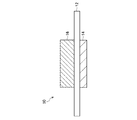
図1において、本発明を実施した一体構造物10は、蓄電デバイス、例えば、リチウムイオン電池、マグネシウムイオン電池、ナトリウムイオン電池などの二次電池や、電気二重層キャパシタ、リチウムイオンキャパシタなどの電気化学キャパシタに使用される。本実施形態では、一体構造物10を、蓄電デバイスとしてのリチウムイオン電池(以下、二次電池と称する)に用いる例について説明する。二次電池は、図示しないセル容器の内部に、一体構造物10の他、正極リードと負極リードと電解液(いずれも図示なし)を収容した状態で密閉して製造される。正極リードは、セル容器の外部に設けられた正極端子と後述する正極16とを接続する。負極リードは、セル容器の外部に設けられた負極端子と後述する負極14とを接続する。電解液は、電解質を含む液体であり、電解質を溶媒に溶解させた溶液や、溶媒和電解質からなる高濃度電解液、および電解質自体が液体となっているイオン液体などがある。電解質は特に限定されず、LiPF6、LiClO4、LiBF4、LiAsF6等のリチウム塩を用いることができる。溶媒も特に限定されず、環状カーボネート、鎖状カーボネート等のうちの一種以上を用いることができる。環状カーボネートとしては、プロピレンカーボネート(PC)、エチレンカーボネート(EC)、フルオロエチレンカーボネート(FEC)、等が挙げられる。鎖状カーボネートとしては、ジエチルカーボネート(DEC)、ジメチルカーボネート(DMC)等が挙げられる。電解液として、例えば、ECとDECを体積比1:1で混合した溶液に、1.0モル/リットルのLiPF6を溶解させたものが用いられる。
1. In FIG. 1, an integrated
一体構造物10は、セパレータ12と、負極14と、正極16とを備える。一体構造物10は、セパレータ12の一方の表面に負極14が積層され、セパレータ12の他方の表面に正極16が積層された三層構造の膜である。本実施形態では、一体構造物10は、セパレータ12と負極14と正極16とが一体に形成されている。なお、一体構造物は、セパレータ12と負極14とが一体に形成された二層構造の膜でもよいし、セパレータ12と正極16とが一体に形成された二層構造の膜でもよい。さらには、一体構造物は、負極14と正極16とがセパレータ12を介して交互に積層された多層構造の膜でもよい。
The integrated
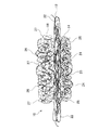
図2に示すように、セパレータ12は、絶縁性繊維22のスポンジ状構造体からなる。スポンジ状構造体は、内部に複数の隙間を有する膜である。スポンジ状構造体としては、例えば不織布が挙げられる。
As shown in FIG. 2, the
セパレータ12の空隙率は、機械的強度や短絡耐性が確保でき、所望のイオンの拡散性が得られれば特に限定されないが、例えば10%以上99%以下の範囲内とされる。セパレータ12の空隙率は、50%以上95%以下の範囲内であることがより好ましく、60%以上90%以下の範囲内であることが特に好ましい。セパレータ12の空隙率は、試験用に切り出した膜の体積と重量により求めた。
The porosity of the
セパレータ12の厚みは、例えば1μm以上30μm以下の範囲内とされる。セパレータ12の厚みは、3μm以上20μm以下の範囲内であることがより好ましく、5μm以上16μm以下の範囲内であることが特に好ましい。
The thickness of the
絶縁性繊維22は、窒化ホウ素ナノチューブ(BNNT)または有機系ナノファイバーである。有機系ナノファイバーとしては、セルロースナノファイバー(CNF;cellulose nanofiber)、キチンナノファイバー等が挙げられる。絶縁性繊維22は、電気絶縁性と化学的安定性と熱的安定性の観点から、BNNTであることが好ましい。本実施形態では、絶縁性繊維22としてBNNTが用いられる。
The insulating
絶縁性繊維22の長さは、例えば0.1μm以上10mm以下の範囲内とされる。絶縁性繊維22の直径は、例えば0.5nm以上100nm以下の範囲内とされる。絶縁性繊維22が細いほど、また長いほど、繊維間の相互作用が強く、セパレータ12の機械的強度が確保し易いためである。なお、絶縁性繊維22が細すぎると、セパレータ12の内部の隙間が狭くなりすぎる。絶縁性繊維22が長すぎると、後述する第2分散液32の調整が難しくなる。
The length of the insulating
負極14は、セパレータ12の一方の表面に設けられている。負極14は、導電性繊維24と負極活物質25とを有し、導電性繊維24のスポンジ状構造体の内部に負極活物質25が保持された電極である。導電性繊維24のスポンジ状構造体が、三次元集電体として機能するため、負極14は金属箔集電体を有さない。本実施形態では、導電性繊維24のスポンジ状構造体として、導電性繊維24の不織布が用いられる。負極14の空隙率は、例えば5%〜80%であり、好ましくは10%〜30%である。負極14の厚みは、例えば10μm〜100μmである。導電性繊維24としては、カーボンナノチューブ(CNT;carbon nanotube)が用いられる。CNTとしては、例えば、直径1nm〜15nm程度、平均長さ10μm〜1000μm程度のものが用いられる。負極活物質25は、例えば粒子状に形成されている。負極活物質25としては、グラファイト等の炭素材料、シリコンやスズ等のリチウムと反応して化合物を形成する材料、チタン酸リチウム等のリチウム複合酸化物等が用いられる。本実施形態では、導電性繊維24としてCNTが用いられ、負極活物質25としてグラファイトが用いられる。この例では、CNTは、数枚のグラフェンシートが同心円状に巻かれた数層CNT(FWCNT;Few Wall CNT)であるが、これに限られず、1枚のグラフェンシートが円筒状に巻かれた単層CNT(SWCNT;Single Wall CNT)、2枚のグラフェンシートが同心円状に巻かれた二層CNT(DWCNT;Double Wall CNT)、多数のグラフェンシートが同心円状に巻かれた多層CNT(MWCNT;Multi Wall CNT)でもよい。導電性、自立性や活物質との電気的接続の観点からは層数が少ないほど良く、充放電動作時の不可逆容量低減の観点からは層数が多く比表面積が小さいほど良く、活物質に合わせて適切なCNTを選ぶことができる。
The
正極16は、セパレータ12の他方の表面に設けられている。正極16は、導電性繊維26と正極活物質27とを有し、導電性繊維26のスポンジ状構造体の内部に正極活物質27が保持された電極である。導電性繊維26のスポンジ状構造体が、三次元集電体として機能するため、正極16は金属箔集電体を有さない。本実施形態では、導電性繊維26のスポンジ状構造体として、導電性繊維26の不織布が用いられる。正極16の空隙率は、例えば5%〜80%であり、好ましくは10%〜30%である。正極16の厚みは、例えば10μm〜100μmである。導電性繊維26としては、CNTが用いられる。正極活物質27は、例えば粒子状に形成されている。正極活物質27としては、コバルト酸リチウム(LiCoO2)、マンガン酸リチウム(LiMn2O4)、リン酸鉄リチウム(LiFePO4)、二種以上の遷移金属を複合化したNMC(LiNixMnyCozO2)やNCA(LiNixCoyAlzO2)、および硫黄等が用いられる。本実施形態では、導電性繊維26としてCNTが用いられ、正極活物質27としてLiCoO2が用いられる。
The
一体構造物10の製造方法について、図3A,図3Bを用いて以下に説明する。
The manufacturing method of the
一体構造物10は、負極14を形成する第1分散液30とセパレータ12を形成する第2分散液32と正極16を形成する第3分散液34とを準備する分散液準備工程と、第1〜第3分散液30〜34を用いてセパレータ12と電極としての負極14及び正極16を一体に形成するセパレータ及び電極一体形成工程とにより製造される。
The
分散液準備工程は、導電性繊維24と負極活物質25とが第1溶媒に分散した第1分散液30を調製する第1分散液調製工程と、絶縁性繊維22が第2溶媒に分散した第2分散液32を調製する第2分散液調製工程と、導電性繊維26と正極活物質27とが第3溶媒に分散した第3分散液34を調製する第3分散液調製工程とを有する。
In the dispersion preparation step, the first dispersion preparation step for preparing the
第1分散液調製工程は、導電性繊維24と負極活物質25と適量の第1溶媒との混合物に対して分散処理を行い、導電性繊維24と負極活物質25とを共分散させることにより、第1分散液30を調製する。第1溶媒としては、2-propanol、エタノール、ドデシルベンゼンスルホン酸ナトリウム(SDBS)水溶液等が用いられる。分散処理としては、超音波分散処理、ボールミル、ビーズミル、ジェットミル等が挙げられる。導電性繊維24としてのCNTは、例えばCVD法により合成される。CNTは、流動層CVD法、浮遊触媒CVD法、基板担持触媒CVD法などにより合成してもよい。
In the first dispersion preparation step, a dispersion treatment is performed on a mixture of the
第2分散液調製工程は、絶縁性繊維22と適量の第2溶媒との混合物に対して分散処理を行うことにより、第2分散液32を調製する。第2溶媒としては、2-propanol、エタノール、アセトン、ドデシルベンゼンスルホン酸ナトリウム水溶液等が用いられる。第2分散液調製工程は、特許請求の範囲に記載の「分散液調製工程」に対応する。
In the second dispersion preparation step, the
第3分散液調製工程は、導電性繊維26と正極活物質27と適量の第3溶媒との混合物に対して分散処理を行い、導電性繊維26と正極活物質27とを共分散させることにより、第3分散液34を調製する。導電性繊維26としてのCNTは、第1分散液調製工程と同様の手法で得られたものが用いられる。
In the third dispersion preparation step, a dispersion treatment is performed on a mixture of the
セパレータ及び電極一体形成工程は、第1分散液30、第2分散液32、第3分散液34をこの順にろ過することにより、負極14とセパレータ12と正極16とが一体化された一体構造物10を形成する。図3Aに示す連続成膜装置40は、一体構造物製造装置の一例である。連続成膜装置40は、図示しない送出ロールと巻取ロールにより搬送される長尺のフィルタ42の表面に第1〜第3分散液30〜34を連続的に塗布し、第1〜第3分散液30〜34のろ過を行うことにより一体構造物10を製造する。フィルタ42は、例えば孔径が0.1μm〜5μmの多孔質膜である。フィルタ42は、特許請求の範囲に記載の「支持体」に対応する。連続成膜装置40は、第1分散液30を塗布するための第1のダイ44と、第2分散液32を塗布するための第2のダイ46と、第3分散液34を塗布するための第3のダイ48とを備える。第1〜第3のダイ44〜48は、フィルタ42の表面に対向し、かつ、フィルタ42の幅方向に延びるスリット状の流出口(図示なし)を有し、第1〜第3分散液30〜34を各流出口から連続的に流出する。この例では、フィルタ42の幅方向の両端部に正極リード50と負極リード52が配置されている。図3Bに示すように、正極リード50は正極16と接続され、負極リード52は負極14と接続される。なお、連続成膜装置40は、フィルタ42を搬送することに代えて、または加えて、第1〜第3のダイ44〜48を移動させてもよい。連続成膜装置40は、図示しない減圧ポンプを用いて吸引ろ過法を行うこととしてもよい。また、温風を用いた加圧ろ過やヒーターの併用により、ろ過と蒸発により溶媒の除去を促進しても良い。また、圧搾することで一体構造物10から溶媒を除去しても良い。さらに、フィルタ42に代えて孔のない支持体を用い、減圧乾燥または加熱乾燥により溶媒を除去しても良い。加えて、第1〜第3のダイ44〜48に代えてスプレーノズルを用い、第1〜第3分散液30〜34をスプレーコートしても良い。
In the separator and electrode integrated formation step, the
セパレータ及び電極一体形成工程は、第1分散液30から第1溶媒を除去して負極14を形成する負極形成工程と、第2分散液32から第2溶媒を除去してセパレータ12を形成するセパレータ形成工程と、第3分散液34から第3溶媒を除去して正極16を形成する正極形成工程とを有する。セパレータ及び電極一体形成工程における上記各工程について具体的に説明する。
The separator and electrode integrated forming step includes a negative electrode forming step in which the first solvent is removed from the
負極形成工程は、第1分散液30をフィルタ42に供給し、導電性繊維24をフィルタ42の表面で集積させることにより、導電性繊維24のスポンジ状構造体に負極活物質25が保持された負極14を形成する。第1分散液30に含まれる第1溶媒は、フィルタ42を通過する。第1分散液30に含まれる導電性繊維24は、フィルタ42の表面で負極活物質25を取り込みながら絡まり合うことにより、スポンジ状構造体としての不織布を形成する。こうして、導電性繊維24の不織布の隙間に負極活物質25が保持された負極14がフィルタ42上に形成される。
In the negative electrode forming step, the
セパレータ形成工程は、第2分散液32をフィルタ42上の負極14の上に供給し、絶縁性繊維22を負極14の表面で集積させることにより、絶縁性繊維22のスポンジ状構造体からなるセパレータ12を形成する。第2分散液32に含まれる第2溶媒は、負極14とフィルタ42を通過する。第2分散液32に含まれる絶縁性繊維22は、負極14を通過せずに、負極14の表面で絡まり合うことにより、スポンジ状構造体としての不織布を形成する。こうして、絶縁性繊維22の不織布からなるセパレータ12が形成される。セパレータ12と負極14との界面では、絶縁性繊維22と導電性繊維24とが互いに絡まり合う。これにより、セパレータ12が負極14と一体に形成される。
In the separator forming step, the
正極形成工程は、第3分散液34をフィルタ42上のセパレータ12の上に供給し、導電性繊維26をセパレータ12の表面で集積させることにより、導電性繊維26のスポンジ状構造体に正極活物質27が保持された正極16を形成する。第3分散液34に含まれる第3溶媒は、セパレータ12、負極14、及び、フィルタ42を順に通過する。第3分散液34に含まれる導電性繊維26は、セパレータ12の表面で正極活物質27を取り込みながら絡まり合うことにより、スポンジ状構造体としての不織布を形成する。こうして、導電性繊維26の不織布の隙間に正極活物質27が保持された正極16が形成される。正極16とセパレータ12との界面では、導電性繊維26と絶縁性繊維22とが互いに絡まり合う。これにより、正極16がセパレータ12と一体に形成される。
In the positive electrode forming step, the
セパレータ及び電極一体形成工程により得られた一体構造物10は、フィルタ42から分離して自立膜として回収する。また、必要に応じて、フィルタ42からの分離前または分離後に乾燥機を用いて乾燥させる。
The
以上のように、セパレータ12は、絶縁性繊維22のスポンジ状構造体からなり、高分子材料が含まれないので、空隙率を高くすることができ、二次電池におけるイオンの拡散性の向上を図れる。特に、セパレータ12は、1000℃以上の耐熱性を有する絶縁性繊維22としてのBNNTのスポンジ状構造体のみからなるので、高分子材料の熱分解の問題がなく、優れた耐熱性を有する。また、セパレータ12は、第2分散液32から第2溶媒を除去して作られるので、予め形成した電極の上に第2分散液32を供給することにより、電極の表面の凹凸形状に追従して必要最低限の厚みで絶縁性を発現することができる。
As described above, the
一体構造物10は、正極16と負極14とがそれぞれの分散液から溶媒を除去して形成されるので、それぞれの分散液の量を調整することにより正極16と負極14との各層の厚みを任意の値に設定することができる。また、一体構造物10は、正極16と負極14とが金属箔集電体を有さないので、金属箔集電体の厚みの分だけ正極16と負極14の各層の厚みを小さくすることができる上、正極16と負極14との各層の厚みを小さくしても二次電池の中の正極16と負極14の割合を高く保つことができる。すなわち、二次電池の中の正極活物質27と負極活物質25の質量割合を高くすることができ、二次電池の高容量化を図れる。また、一体構造物10は、セパレータ12と負極14と正極16との各層の厚みが小さいため、電解液中のイオンの拡散が促進され、二次電池における高出力化を図れる。さらに、一体構造物10は、セパレータ12と負極14と正極16が一体に形成されるので、各層の厚みが小さいにもかかわらず機械的強度に優れる。すなわち、一体構造物10は、高出力化及び高容量化の向上と機械的強度の確保を両立した二次電池を実現できる。特に、一体構造物10は、絶縁性繊維22としてBNNTを用い、導電性繊維24,26としてCNTを用いているので、より耐熱性に優れた二次電池を実現できる。
Since the
なお、セパレータ及び電極一体形成工程は、上記実施形態では負極形成工程、セパレータ形成工程、正極形成工程の順に実施しているが、正極形成工程、セパレータ形成工程、負極形成工程の順に実施してもよい。 In addition, in the said embodiment, although the separator and electrode integrated formation process is implemented in order of the negative electrode formation process, the separator formation process, and the positive electrode formation process, you may implement in order of a positive electrode formation process, a separator formation process, and a negative electrode formation process. Good.
負極と正極とがセパレータを介して交互に積層された多層構造の一体構造物を製造する場合は、負極形成工程とセパレータ形成工程と正極形成工程との各工程を複数回実施する。例えば、セパレータ及び電極一体形成工程では、セパレータ形成工程、負極形成工程、セパレータ形成工程、正極形成工程、セパレータ形成工程、・・・と繰り返し実施する。セパレータ及び電極一体形成工程において最初に実施する工程は、負極形成工程とセパレータ形成工程と正極形成工程とのうちいずれの工程でもよい。 When manufacturing a monolithic structure having a multilayer structure in which the negative electrode and the positive electrode are alternately laminated via the separator, each of the negative electrode forming step, the separator forming step, and the positive electrode forming step is performed a plurality of times. For example, in the separator and electrode integrated formation step, the separator formation step, the negative electrode formation step, the separator formation step, the positive electrode formation step, the separator formation step, and so on are repeated. The step performed first in the separator and electrode integrated formation step may be any step among a negative electrode formation step, a separator formation step, and a positive electrode formation step.
セパレータ及び電極一体形成工程は、上記実施形態ではセパレータ形成工程の他に電極形成工程として負極形成工程と正極形成工程を含むが、負極形成工程と正極形成工程のうちいずれかの工程のみを実施してもよい。例えば、負極形成工程と正極形成工程のうち負極形成工程のみを実施する場合は、セパレータと負極とが一体に形成された一体構造物が製造される。セパレータ形成工程と負極形成工程とを実施する順番は適宜変更してよく、また、分散液準備工程においては、第3分散液調製工程を実施せずに、第1分散液調製工程と第2分散液調製工程を実施することが好ましい。負極形成工程と正極形成工程のうち正極形成工程のみを実施する場合は、セパレータと正極とが一体に形成された一体構造物が製造される。セパレータ形成工程と正極形成工程とを実施する順番は適宜変更してよく、また、分散液準備工程においては、第1分散液調製工程を実施せずに、第2分散液調製工程と第3分散液調製工程を実施することが好ましい。 In the embodiment described above, the separator and electrode integrated formation step includes a negative electrode formation step and a positive electrode formation step as an electrode formation step in addition to the separator formation step, but only one of the negative electrode formation step and the positive electrode formation step is performed. May be. For example, when only the negative electrode forming step is performed among the negative electrode forming step and the positive electrode forming step, an integrated structure in which the separator and the negative electrode are integrally formed is manufactured. The order in which the separator forming step and the negative electrode forming step are performed may be appropriately changed. In the dispersion preparing step, the first dispersion preparing step and the second dispersing step are not performed without performing the third dispersion preparing step. It is preferable to carry out the liquid preparation step. When only the positive electrode forming step is performed among the negative electrode forming step and the positive electrode forming step, an integrated structure in which the separator and the positive electrode are integrally formed is manufactured. The order of performing the separator forming step and the positive electrode forming step may be appropriately changed. In the dispersion preparing step, the second dispersion preparing step and the third dispersing step are not performed without performing the first dispersion preparing step. It is preferable to carry out the liquid preparation step.
セパレータ及び電極一体形成工程に含まれる負極形成工程と正極形成工程とセパレータ形成工程とのうち、いずれかの工程を独立して実施してもよい。例えば、セパレータ形成工程を独立して実施する場合は、セパレータのみが製造される。セパレータ形成工程を独立して実施する場合は、分散液準備工程に含まれる第1分散液調製工程と第2分散液調製工程と第3分散液調製工程とのうち、第2分散液調製工程を独立して実施することが好ましい。すなわち、セパレータの製造方法は、第2分散液調製工程とセパレータ形成工程とを有する。また、負極形成工程を独立して実施する場合は、負極のみが製造される。負極形成工程を独立して実施する場合は、第1分散液調製工程を独立して実施することが好ましい。正極形成工程を独立して実施する場合は、正極のみが製造される。正極形成工程を独立して実施する場合は、第3分散液調製工程を独立して実施することが好ましい。 Any of the negative electrode forming step, the positive electrode forming step, and the separator forming step included in the separator and electrode integrated forming step may be performed independently. For example, when the separator forming step is performed independently, only the separator is manufactured. In the case where the separator forming step is performed independently, the second dispersion preparing step is included among the first dispersion preparing step, the second dispersion preparing step, and the third dispersion preparing step included in the dispersion preparing step. It is preferable to carry out independently. That is, the manufacturing method of a separator has a 2nd dispersion liquid preparation process and a separator formation process. Further, when the negative electrode forming step is performed independently, only the negative electrode is produced. When carrying out the negative electrode forming step independently, it is preferable to carry out the first dispersion preparation step independently. When the positive electrode forming step is performed independently, only the positive electrode is manufactured. When the positive electrode forming step is carried out independently, it is preferable to carry out the third dispersion preparation step independently.
セパレータ12の空隙率は、例えば、プレスなどの処理を施すことによって調節することができる。また、セパレータ12を水またはエタノールで洗浄することにより、セパレータ12の空隙率を調節することもできる。セパレータ12を水で洗浄した場合は、水の表面張力が高いためセパレータ12が収縮し、空隙率が下がる。セパレータ12をエタノールなどの有機溶剤で洗浄した場合は、有機溶剤の表面張力が低いためセパレータ12があまり収縮せず、空隙率が上がる。また、特定の溶媒に溶ける犠牲粒子を絶縁性繊維22とともに第2溶媒に入れて第2分散液32を調製し、この第2分散液32を用いてセパレータ12を形成した後、犠牲粒子を特定の溶媒で溶かすことにより、セパレータ12の空隙率を調節することもできる。さらに、溶媒除去工程をフリーズドライ法により行うことでも、セパレータ12の空隙率を調節することができる。
The porosity of the
2.実施例
絶縁性繊維のスポンジ状構造体からなるセパレータと正極と負極とを別々に製造し、正極と負極の間にセパレータを挟んで作製した電極構造体を用いた電気化学セルを実施例1とした。絶縁性繊維のスポンジ状構造体からなるセパレータと正極とを一体に形成した一体構造物と、絶縁性繊維のスポンジ状構造体からなるセパレータと負極とを一体に形成した一体構造物とを製造し、各一体構造物のセパレータ同士を向い合せて重ねることにより作製した電極構造体を用いた電気化学セルを実施例2とした。絶縁性繊維のスポンジ状構造体からなるセパレータと正極と負極とを、セパレータが正極と負極を隔てるように一体に形成した一体構造物を製造し、この一体構造物を電極構造体として用いた電気化学セルを実施例3とした。正極と負極とを別々に製造して、正極と負極の間に市販のポリプロピレン製セパレータを挟んで作製した電極構造体を用いた電気化学セルを比較例1とした。正極は、導電性繊維としてCNTを用い、正極活物質としてLiCoO2を用いて製造した。負極は、導電性繊維としてCNTを用い、負極活物質としてグラファイトを用いて製造した。実施例1〜3、比較例1の各電気化学セルは、上記実施形態と同様の手法で作った電解液を用いて作製した。
2. Example An electrochemical cell using an electrode structure manufactured by separately manufacturing a separator made of a sponge-like structure of insulating fibers, a positive electrode, and a negative electrode, and sandwiching the separator between the positive electrode and the negative electrode, and Example 1 did. An integrated structure in which a separator made of a sponge-like structure of insulating fiber and a positive electrode are integrally formed, and an integrated structure in which a separator made of a sponge-like structure of insulating fiber and a negative electrode are integrally formed are manufactured. Example 2 was an electrochemical cell using an electrode structure produced by stacking the separators of each integral structure facing each other. Manufacturing an integrated structure in which a separator made of a sponge-like structure of insulating fibers, a positive electrode, and a negative electrode are integrally formed so that the separator separates the positive electrode and the negative electrode, and this integrated structure is used as an electrode structure. The chemical cell was referred to as Example 3. Comparative Example 1 was an electrochemical cell using an electrode structure produced by separately producing a positive electrode and a negative electrode and sandwiching a commercially available polypropylene separator between the positive electrode and the negative electrode. The positive electrode was manufactured using CNT as the conductive fiber and LiCoO 2 as the positive electrode active material. The negative electrode was manufactured using CNT as the conductive fiber and graphite as the negative electrode active material. Each electrochemical cell of Examples 1 to 3 and Comparative Example 1 was prepared using an electrolytic solution prepared by the same method as in the above embodiment.
実施例1のセパレータと正極と負極、実施例2の各一体構造物、実施例3の一体構造物、比較例1の正極と負極は、図4に示すろ過装置60を用いて製造した。ろ過装置60は、一体構造物製造装置の一例であり、第1〜第3分散液30〜34を受け入れる漏斗61、第1〜第3分散液30〜34のろ過を行うフィルタ62、フィルタ62を支持するフィルタベース63、フィルタベース63に設けられた多孔性部63a、フィルタ62と多孔性部63aを通過した第1〜第3溶媒を受け入れる吸引容器64、図示しない減圧ポンプと接続し、吸引容器64の内部を減圧させる吸引口65などにより構成される。フィルタ62は、メルク社製のオムニポアメンブレンフィルター JAWP02500を用いた。吸引容器64の内部の圧力は50kPaとした。
The separator, the positive electrode, and the negative electrode of Example 1, each integrated structure of Example 2, the integrated structure of Example 3, and the positive electrode and negative electrode of Comparative Example 1 were manufactured using the
実施例1では、絶縁性繊維22としてBNNT社製のBNNTを使用し、導電性繊維24として特許第5447367号公報、特許第5862559号公報、D.Y. Kim, H. Sugime, K. Hasegawa, T. Osawa, and S. Noda, Carbon 49(6), 1972-1979 (2011).、Z. Chen, D.Y. Kim, K. Hasegawa, T. Osawa, and S. Noda, Carbon 80, 339-350 (2014).などに記載されている流動層CVD法により合成したCNTを使用した。CNTの平均長さは約200μmであり、平均直径は約10nmである。第1分散液調製工程において、負極活物質25としてSECカーボン社製のSECファインパウダーSNO-10(グラファイト)を使用し、第1溶媒として2-propanolを使用し、CNTの質量比を3wt%とし、グラファイトの質量比を97wt%とした混合物に、2-propanolを20mL加え、超音波洗浄器を用いて10分間超音波分散処理を行うことにより、第1分散液30を調製した。第2分散液調製工程において、第2溶媒として2-propanolを使用し、濃度換算でBNNT1mgに対し2-propanolを10mL加え、10分間超音波分散処理を行うことにより、第2分散液32を調製した。第3分散液調製工程において、正極活物質27として株式会社豊島製作所製のLiCoO2(商品コード:381-04661)を使用し、第3溶媒として2-propanolを使用し、CNTの質量比を3wt%とし、LiCoO2の質量比を97wt%とした混合物に、2-propanolを20mL加え、10分間超音波分散処理を行うことにより、第3分散液34を調製した。ろ過装置60を用いて、セパレータ形成工程と正極形成工程と負極形成工程とを独立して実施することにより、セパレータと正極と負極とを別々に製造した。セパレータは、厚みが33μmであり、空隙率が79%である。正極は、厚みが45μmであり、面密度が4.37mg/cm2である。負極は、厚みが23μmであり、面密度が1.43mg/cm2である。正極、セパレータ、負極の単位面積あたりの質量の合計値に対する活物質の質量割合は83%であり、このうち正極活物質の質量割合は62%であり、負極活物質の質量割合は20%である。
In Example 1, BNNT manufactured by BNNT was used as the insulating
実施例2では、第1分散液調製工程と第3分散液調製工程は、実施例1と同様に実施し、第2分散液調製工程は、絶縁性繊維22としてSigma-Aldrich社製のBNNTを使用したこと以外は実施例1と同様に実施した。ろ過装置60を用いて、セパレータ形成工程と正極形成工程とを実施することによりセパレータと正極とを一体に形成した一体構造物を製造し、セパレータ形成工程と負極形成工程とを実施することによりセパレータと負極とを一体に形成した一体構造物を製造した。以降の説明では、各一体構造物により作製された電極構造体のうち、2つのセパレータが重ねられた部分を、セパレータと記載する。セパレータは、厚みが16μmであり、空隙率が62%である。正極は、厚みが43μmであり、面密度が3.64mg/cm2である。負極は、厚みが18μmであり、面密度が0.98mg/cm2である。正極、セパレータ、負極の単位面積あたりの質量の合計値に対する活物質の質量割合は81%であり、このうち正極活物質の質量割合は64%であり、負極活物質の質量割合は17%である。
In Example 2, the first dispersion preparation step and the third dispersion preparation step are performed in the same manner as in Example 1. In the second dispersion preparation step, BNNT made by Sigma-Aldrich is used as the insulating
実施例3では、第1〜第3分散液調製工程を実施例1と同様に実施した。ろ過装置60を用いて、正極形成工程とセパレータ形成工程と負極形成工程とを順に実施することにより、セパレータと正極と負極とを一体に形成した一体構造物を製造した。セパレータ形成工程では、使用する第2分散液32の全量の半分の量でのろ過が完了した段階で温風を用いた乾燥工程を実施し、乾燥により形成される孔を閉塞させるように残りの第2分散液32をろ過した。セパレータは、厚みが22μmであり、空隙率が85%である。正極は、厚みが27μmであり、面密度が2.78mg/cm2である。負極は、厚みが17μmであり、面密度が0.86mg/cm2である。正極、セパレータ、負極の単位面積あたりの質量の合計値に対する活物質の質量割合は85%であり、このうち正極活物質の質量割合は65%であり、負極活物質の質量割合は20%である。
In Example 3, the first to third dispersion preparation steps were performed in the same manner as in Example 1. By using the
比較例1では、第1分散液調製工程と第3分散液調製工程を実施例1と同様に実施した。ろ過装置60を用いて、正極形成工程と負極形成工程を独立して実施することにより、正極と負極とを別々に製造した。セパレータは、ポリプロピレン製の市販品であり、厚みが24μmであり、空隙率が55%である。正極は、厚みが35μmであり、直面密度が3.67mg/cm2である。負極は、厚みが26μmであり、面密度が1.35mg/cm2である。正極、セパレータ、負極の単位面積あたりの質量の合計値に対する活物質の質量割合は81%であり、このうち正極活物質の質量割合は59%であり、負極活物質の質量割合は22%である。
In Comparative Example 1, the first dispersion preparation step and the third dispersion preparation step were performed in the same manner as in Example 1. By using the
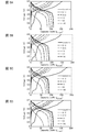
実施例1〜3、比較例1の各電気化学セルについて、充放電試験を行った。北斗電工社製の充放電装置 HJ1001SD8を用いて充放電曲線の測定を行った。充放電装置は、定電流条件で電圧の経時変化を測定する設定とした。充放電は、0.1C、0.2C、0.3C、0.4C、0.5C、0.6C、0.8C、1C、1.5C、2C、3C、4C、5C、6C、8C、10Cの各Cレート(Capacity rate)で3回ずつ順番に行った。Cレートは、電池の容量(Ah)に対する充放電時の電流値(A)の数値部分の比(電流/容量)を示す。充放電のサイクルは、3サイクルとした。カットオフ電圧は、3.0V〜4.2Vとした。充放電試験の結果を図5A〜図5Dに示す。図5Aは実施例1の電気化学セルの充放電試験の結果を示し、図5Bは実施例2の電気化学セルの充放電試験の結果を示し、図5Cは実施例3の電気化学セルの充放電試験の結果を示し、図5Dは比較例1の電気化学セルの充放電試験の結果を示す。図5A〜図5Dは、縦軸が電圧、横軸が充放電容量を示す。図5A〜図5Dでは、0.1C、0.3C、1C、3C、10Cについての結果を示す。図中「Initial 0.1C」は、0.1Cにおける初回の充放電の結果を示す。実施例1〜3と比較例1とを比べると、充電容量および放電容量が同程度であることがわかる。これより、BNNTのスポンジ状構造体からなるセパレータは、電極と一体に形成した場合でも電極と別体に形成した場合でも、二次電池におけるセパレータとして機能することが確認できた。特に、実施例1〜3の電気化学セルは、有機物セパレータを用いた比較例1とは異なり、1000℃以上の耐熱性を有するBNNTのスポンジ状構造体からなるセパレータを用いて構成されているので、高い耐熱性が期待できる。実施例2,3と比較例1とを比べると、実施例2,3の電気化学セルは、セパレータの厚みが、比較例1のポリプロピレン製セパレータの厚みよりも小さいにもかかわらず、比較例1の電気化学セルと同等の充放電特性を示すことが確認できた。 About each electrochemical cell of Examples 1-3 and the comparative example 1, the charging / discharging test was done. The charge / discharge curve was measured using a charge / discharge device HJ1001SD8 manufactured by Hokuto Denko Corporation. The charging / discharging device was set to measure voltage change with time under constant current conditions. Charge / discharge is 0.1C, 0.2C, 0.3C, 0.4C, 0.5C, 0.6C, 0.8C, 1C, 1.5C, 2C, 3C, 4C, 5C, 6C, 8C, The test was performed three times in sequence at each C rate (Capacity rate) of 10C. The C rate indicates the ratio (current / capacity) of the numerical value portion of the current value (A) during charging / discharging to the capacity (Ah) of the battery. The charge / discharge cycle was 3 cycles. The cut-off voltage was 3.0V to 4.2V. The results of the charge / discharge test are shown in FIGS. 5A to 5D. 5A shows the result of the charge / discharge test of the electrochemical cell of Example 1, FIG. 5B shows the result of the charge / discharge test of the electrochemical cell of Example 2, and FIG. 5C shows the charge / discharge test of the electrochemical cell of Example 3. The result of the discharge test is shown, and FIG. 5D shows the result of the charge / discharge test of the electrochemical cell of Comparative Example 1. 5A to 5D, the vertical axis represents voltage, and the horizontal axis represents charge / discharge capacity. 5A to 5D show the results for 0.1C, 0.3C, 1C, 3C, and 10C. In the figure, “Initial 0.1C” indicates the result of the initial charge / discharge at 0.1C. Comparing Examples 1 to 3 and Comparative Example 1, it can be seen that the charge capacity and the discharge capacity are comparable. From this, it was confirmed that the separator composed of the BNNT sponge-like structure functions as a separator in the secondary battery, whether formed integrally with the electrode or formed separately from the electrode. In particular, the electrochemical cells of Examples 1 to 3 are configured using a separator made of a BNNT sponge-like structure having a heat resistance of 1000 ° C. or higher, unlike Comparative Example 1 using an organic separator. High heat resistance can be expected. When Examples 2 and 3 are compared with Comparative Example 1, the electrochemical cells of Examples 2 and 3 have Comparative Example 1 although the thickness of the separator is smaller than the thickness of the polypropylene separator of Comparative Example 1. It was confirmed that the same charge / discharge characteristics as those of the electrochemical cell were exhibited.
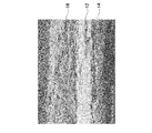
上記実施形態に記載の製造方法により製造される一体構造物の断面形状を確認するために、ろ過装置60を用いて、所定条件でセパレータ形成工程と正極形成工程と負極形成工程とを実施することにより、セパレータと正極と負極とを一体に形成した一体構造物を製造し、実施例4とした。図6は、実施例4の一体構造物の断面を走査型電子顕微鏡(SEM;Scanning Electron Microscope)により撮影して得られたSEM画像である。図6から、実施例4の一体構造物は、セパレータ12と負極14と正極16とが混ざり合うことなく分かれており、三層構造となっていることが確認できた。また、実施例4の一体構造物は、セパレータ12と負極14と正極16とが一体に形成されていることがわかる。
In order to confirm the cross-sectional shape of the integrated structure manufactured by the manufacturing method described in the above embodiment, the separator forming step, the positive electrode forming step, and the negative electrode forming step are performed under predetermined conditions using the
以上のように、絶縁性繊維からなる、薄くて耐熱性とイオンの拡散性とに優れたセパレータ12が得られ、同様の特徴を持つリチウムイオン電池を実現できる。また、セパレータ12、正極16、負極14を含む一体構造物10の機械的強度と正極活物質27と負極活物質25の質量割合を損なうことなく、セパレータ12、正極16、負極14の各層の厚みを小さくし、耐熱性とイオンの拡散性とに優れたリチウムイオン電池を実現できる。リチウムイオン電池以外の二次電池であるマグネシウムイオン電池やナトリウムイオン電池などの場合も、リチウムイオン電池と同様の効果を得ることができる。さらに、電気二重層キャパシタやリチウムイオンキャパシタなどの電気化学キャパシタの場合も、二次電池の場合と同様の効果を得られる。
As described above, a
10 一体構造物
12 セパレータ
14 負極
16 正極
22 絶縁性繊維
24 導電性繊維
25 負極活物質
26 導電性繊維
27 正極活物質
30 第1分散液
32 第2分散液
34 第3分散液
40 連続成膜装置
42,62 フィルタ
44 第1のダイ
46 第2のダイ
48 第3のダイ
50 正極リード
52 負極リード
60 ろ過装置
61 漏斗
63 フィルタベース
63a 多孔性部
64 吸引容器
65 吸引口
DESCRIPTION OF
Claims (9)
前記蓄電デバイス用セパレータの表面に設けられ、導電性繊維のスポンジ状構造体の内部に正極活物質または負極活物質が保持された電極と、
を備え、
前記蓄電デバイス用セパレータと前記電極とが一体に形成されていることを特徴とする蓄電デバイス用一体構造物。 The electricity storage device separator according to claim 1,
An electrode having a positive electrode active material or a negative electrode active material held inside a sponge-like structure of conductive fibers, provided on the surface of the electricity storage device separator;
With
The power storage device integrated structure, wherein the power storage device separator and the electrode are integrally formed.
前記導電性繊維は、カーボンナノチューブであることを特徴とする請求項3記載の蓄電デバイス用一体構造物。 The insulating fiber is a boron nitride nanotube or an organic nanofiber,
The integrated structure for an electricity storage device according to claim 3, wherein the conductive fiber is a carbon nanotube.
前記分散液から前記溶媒を除去して前記絶縁性繊維のスポンジ状構造体からなるセパレータを形成するセパレータ形成工程と
を有することを特徴とする蓄電デバイス用セパレータの製造方法。 A dispersion preparation step of preparing a dispersion in which insulating fibers are dispersed in a solvent;
And a separator forming step of forming a separator made of the sponge-like structure of the insulating fiber by removing the solvent from the dispersion.
正極活物質または負極活物質と導電性繊維とが溶媒に分散した分散液を前記支持体上の前記セパレータの上に供給し、前記導電性繊維を前記セパレータの表面で集積させることにより、前記導電性繊維のスポンジ状構造体に前記正極活物質または前記負極活物質が保持された電極を形成する電極形成工程と
を有することを特徴とする蓄電デバイス用一体構造物の製造方法。 Separator formation for forming a separator made of a sponge-like structure of insulating fibers by supplying a dispersion in which insulating fibers are dispersed in a solvent to the support and accumulating the insulating fibers on the surface of the support Process,
A positive electrode active material or a dispersion in which a negative electrode active material and conductive fibers are dispersed in a solvent is supplied onto the separator on the support, and the conductive fibers are accumulated on the surface of the separator to thereby collect the conductive material. And an electrode forming step of forming an electrode in which the positive electrode active material or the negative electrode active material is held on a sponge-like structure of a conductive fiber.
絶縁性繊維が溶媒に分散した分散液を前記支持体上の前記電極の上に供給し、前記絶縁性繊維を前記電極の表面で集積させることにより、前記絶縁性繊維のスポンジ状構造体からなるセパレータを形成するセパレータ形成工程と
を有することを特徴とする蓄電デバイス用一体構造物の製造方法。 A positive electrode active material or a dispersion in which a negative electrode active material and conductive fibers are dispersed in a solvent is supplied to a support, and the conductive fibers are accumulated on the surface of the support to thereby form a sponge-like structure of the conductive fibers. Forming an electrode in which the positive electrode active material or the negative electrode active material is held in a body;
A dispersion liquid in which insulating fibers are dispersed in a solvent is supplied onto the electrode on the support, and the insulating fibers are accumulated on the surface of the electrode, thereby forming a sponge-like structure of the insulating fibers. A method for producing an integrated structure for an electricity storage device, comprising: a separator forming step for forming a separator.
前記導電性繊維は、カーボンナノチューブであることを特徴とする請求項7または8記載の蓄電デバイス用一体構造物の製造方法。 The insulating fiber is a boron nitride nanotube or an organic nanofiber,
The method for manufacturing an integrated structure for an electricity storage device according to claim 7 or 8, wherein the conductive fiber is a carbon nanotube.
Priority Applications (1)
| Application Number | Priority Date | Filing Date | Title |
|---|---|---|---|
| JP2018032431A JP2019149259A (en) | 2018-02-26 | 2018-02-26 | Separator for power storage device, manufacturing method thereof, integral structure for power storage device, and manufacturing method thereof |
Applications Claiming Priority (1)
| Application Number | Priority Date | Filing Date | Title |
|---|---|---|---|
| JP2018032431A JP2019149259A (en) | 2018-02-26 | 2018-02-26 | Separator for power storage device, manufacturing method thereof, integral structure for power storage device, and manufacturing method thereof |
Publications (1)
| Publication Number | Publication Date |
|---|---|
| JP2019149259A true JP2019149259A (en) | 2019-09-05 |
Family
ID=67850621
Family Applications (1)
| Application Number | Title | Priority Date | Filing Date |
|---|---|---|---|
| JP2018032431A Pending JP2019149259A (en) | 2018-02-26 | 2018-02-26 | Separator for power storage device, manufacturing method thereof, integral structure for power storage device, and manufacturing method thereof |
Country Status (1)
| Country | Link |
|---|---|
| JP (1) | JP2019149259A (en) |
Citations (5)
| Publication number | Priority date | Publication date | Assignee | Title |
|---|---|---|---|---|
| JPS5028623B1 (en) * | 1970-03-17 | 1975-09-17 | ||
| JP2008214130A (en) * | 2007-03-05 | 2008-09-18 | Teijin Ltd | Dispersion of boron nitride nanotubes and nonwoven fabric obtained by using the same |
| JP2016031922A (en) * | 2014-07-30 | 2016-03-07 | 本田技研工業株式会社 | Battery electrode doubling as current collector, and battery having the same |
| WO2017136574A1 (en) * | 2016-02-02 | 2017-08-10 | Bnnt, Llc | Nano-porous bnnt composite with thermal switching for advanced batteries |
| WO2017175992A2 (en) * | 2016-04-07 | 2017-10-12 | 주식회사 제낙스 | Electrode assembly and methods for manufacturing electrode assembly and battery |
-
2018
- 2018-02-26 JP JP2018032431A patent/JP2019149259A/en active Pending
Patent Citations (5)
| Publication number | Priority date | Publication date | Assignee | Title |
|---|---|---|---|---|
| JPS5028623B1 (en) * | 1970-03-17 | 1975-09-17 | ||
| JP2008214130A (en) * | 2007-03-05 | 2008-09-18 | Teijin Ltd | Dispersion of boron nitride nanotubes and nonwoven fabric obtained by using the same |
| JP2016031922A (en) * | 2014-07-30 | 2016-03-07 | 本田技研工業株式会社 | Battery electrode doubling as current collector, and battery having the same |
| WO2017136574A1 (en) * | 2016-02-02 | 2017-08-10 | Bnnt, Llc | Nano-porous bnnt composite with thermal switching for advanced batteries |
| WO2017175992A2 (en) * | 2016-04-07 | 2017-10-12 | 주식회사 제낙스 | Electrode assembly and methods for manufacturing electrode assembly and battery |
Similar Documents
| Publication | Publication Date | Title |
|---|---|---|
| AU2018372708B2 (en) | Compositions and methods for energy storage devices having improved performance | |
| CN103132116B (en) | Flexible substrate processing meanss | |
| KR102428230B1 (en) | A method for manufacturing a positive electrode for a lithium ion secondary battery, a lithium ion secondary battery and a positive electrode for a lithium ion secondary battery | |
| WO2018047656A1 (en) | Lithium ion secondary battery and method for manufacturing same | |
| JP2005293950A (en) | Lithium ion secondary battery and charging method of lithium ion secondary battery | |
| JP4087343B2 (en) | Lithium ion secondary battery and method for charging lithium ion secondary battery | |
| JP2022518395A (en) | Compositions and Methods for Prelithiumized Energy Storage Devices | |
| JP2018018821A (en) | Negative electrode comprising mesh-type current collector, lithium secondary battery comprising the same, and manufacturing method thereof | |
| JP5025936B2 (en) | Method for producing electrode-porous sheet composite for electronic component | |
| CN110622342B (en) | Method for manufacturing lithium metal secondary battery including lithium electrode | |
| JP2015060719A (en) | Nonaqueous electrolyte battery | |
| JP2017120746A (en) | Lithium ion secondary battery | |
| JP5766052B2 (en) | Sodium ion secondary battery and method for manufacturing sodium ion secondary battery | |
| JP7367202B2 (en) | Electrode for lithium secondary battery including perforated current collector, method for manufacturing the same, and lithium secondary battery including the electrode | |
| JP2016134296A (en) | Separator integral type electrode, manufacturing method for the same and lithium ion secondary battery using the same | |
| JP6848363B2 (en) | Negative electrode and non-aqueous electrolyte power storage element | |
| KR101615827B1 (en) | Reduced graphene oxide/graphene composite film, Energy Storage Device Having the Same, and Method for Fabricating the composite film | |
| JP2019149259A (en) | Separator for power storage device, manufacturing method thereof, integral structure for power storage device, and manufacturing method thereof | |
| EP4269361A1 (en) | Binder that is composite of single-walled carbon nanotubes and ptfe, and composition for electrode production and secondary battery using same | |
| JP6924047B2 (en) | Rechargeable battery | |
| JP2015225761A (en) | Electrode active material mixture, electrode manufactured by use thereof, and nonaqueous electrolyte secondary battery | |
| CN112042029A (en) | Lithium ion secondary battery, lithium ion capacitor, and methods for producing these | |
| KR20200033511A (en) | Negative electrode for lithium secondary battery and lithium secondary battery comprising the same | |
| KR102634269B1 (en) | Separator for lithium-sulfur battery and an lithium-sulfur battery comprising the same | |
| JP7411966B2 (en) | Secondary battery negative electrode, secondary battery, and manufacturing method of secondary battery negative electrode |
Legal Events
| Date | Code | Title | Description |
|---|---|---|---|
| A621 | Written request for application examination |
Free format text: JAPANESE INTERMEDIATE CODE: A621 Effective date: 20210218 |
|
| A977 | Report on retrieval |
Free format text: JAPANESE INTERMEDIATE CODE: A971007 Effective date: 20211221 |
|
| A131 | Notification of reasons for refusal |
Free format text: JAPANESE INTERMEDIATE CODE: A131 Effective date: 20220104 |
|
| A521 | Request for written amendment filed |
Free format text: JAPANESE INTERMEDIATE CODE: A523 Effective date: 20220302 |
|
| A02 | Decision of refusal |
Free format text: JAPANESE INTERMEDIATE CODE: A02 Effective date: 20220628 |