JP2019103997A - Soil remediation system - Google Patents
Soil remediation system Download PDFInfo
- Publication number
- JP2019103997A JP2019103997A JP2017254858A JP2017254858A JP2019103997A JP 2019103997 A JP2019103997 A JP 2019103997A JP 2017254858 A JP2017254858 A JP 2017254858A JP 2017254858 A JP2017254858 A JP 2017254858A JP 2019103997 A JP2019103997 A JP 2019103997A
- Authority
- JP
- Japan
- Prior art keywords
- iron
- water
- sludge
- discharged
- soil
- Prior art date
- Legal status (The legal status is an assumption and is not a legal conclusion. Google has not performed a legal analysis and makes no representation as to the accuracy of the status listed.)
- Granted
Links
- 239000002689 soil Substances 0.000 title claims abstract description 80
- 238000005067 remediation Methods 0.000 title claims abstract description 14
- XEEYBQQBJWHFJM-UHFFFAOYSA-N Iron Chemical compound [Fe] XEEYBQQBJWHFJM-UHFFFAOYSA-N 0.000 claims abstract description 248
- XLYOFNOQVPJJNP-UHFFFAOYSA-N water Substances O XLYOFNOQVPJJNP-UHFFFAOYSA-N 0.000 claims abstract description 123
- 229910052742 iron Inorganic materials 0.000 claims abstract description 121
- 229910052751 metal Inorganic materials 0.000 claims abstract description 105
- 239000002184 metal Substances 0.000 claims abstract description 105
- 238000005406 washing Methods 0.000 claims abstract description 99
- 239000002738 chelating agent Substances 0.000 claims abstract description 80
- 239000010802 sludge Substances 0.000 claims abstract description 74
- 239000004576 sand Substances 0.000 claims abstract description 48
- 239000012528 membrane Substances 0.000 claims abstract description 31
- 238000001223 reverse osmosis Methods 0.000 claims abstract description 28
- 238000000926 separation method Methods 0.000 claims abstract description 22
- 230000005291 magnetic effect Effects 0.000 claims abstract description 15
- 239000002562 thickening agent Substances 0.000 claims abstract description 14
- 239000000706 filtrate Substances 0.000 claims abstract description 9
- 239000012141 concentrate Substances 0.000 claims abstract description 4
- 239000010419 fine particle Substances 0.000 claims description 154
- 150000002739 metals Chemical class 0.000 claims description 94
- 239000013522 chelant Substances 0.000 claims description 41
- 239000002002 slurry Substances 0.000 claims description 35
- 239000003463 adsorbent Substances 0.000 claims description 33
- 239000007790 solid phase Substances 0.000 claims description 31
- 239000000203 mixture Substances 0.000 claims description 23
- 238000000746 purification Methods 0.000 claims description 15
- 239000010902 straw Substances 0.000 claims description 15
- 238000001914 filtration Methods 0.000 claims description 13
- 230000001172 regenerating effect Effects 0.000 claims description 12
- 150000001875 compounds Chemical class 0.000 claims description 10
- UQSXHKLRYXJYBZ-UHFFFAOYSA-N iron oxide Inorganic materials [Fe]=O UQSXHKLRYXJYBZ-UHFFFAOYSA-N 0.000 claims description 10
- 239000006228 supernatant Substances 0.000 claims description 6
- 229910052739 hydrogen Inorganic materials 0.000 claims description 5
- 239000001257 hydrogen Substances 0.000 claims description 5
- 238000012546 transfer Methods 0.000 claims description 5
- 230000000536 complexating effect Effects 0.000 claims description 4
- 239000012065 filter cake Substances 0.000 claims description 4
- 230000003472 neutralizing effect Effects 0.000 claims description 4
- UFHFLCQGNIYNRP-UHFFFAOYSA-N Hydrogen Chemical compound [H][H] UFHFLCQGNIYNRP-UHFFFAOYSA-N 0.000 claims description 3
- 230000007246 mechanism Effects 0.000 claims description 3
- 238000011083 clear filtration Methods 0.000 claims description 2
- 230000000717 retained effect Effects 0.000 claims description 2
- 238000004062 sedimentation Methods 0.000 claims description 2
- 239000007788 liquid Substances 0.000 abstract description 25
- 238000001179 sorption measurement Methods 0.000 abstract description 20
- CWYNVVGOOAEACU-UHFFFAOYSA-N Fe2+ Chemical compound [Fe+2] CWYNVVGOOAEACU-UHFFFAOYSA-N 0.000 abstract description 12
- 231100000331 toxic Toxicity 0.000 abstract description 5
- 230000002588 toxic effect Effects 0.000 abstract description 5
- 239000012466 permeate Substances 0.000 abstract description 3
- 238000010333 wet classification Methods 0.000 abstract 1
- 239000000243 solution Substances 0.000 description 49
- VYPSYNLAJGMNEJ-UHFFFAOYSA-N Silicium dioxide Chemical compound O=[Si]=O VYPSYNLAJGMNEJ-UHFFFAOYSA-N 0.000 description 42
- 239000002245 particle Substances 0.000 description 24
- 239000002253 acid Substances 0.000 description 21
- 238000003860 storage Methods 0.000 description 19
- 238000004140 cleaning Methods 0.000 description 13
- 230000008929 regeneration Effects 0.000 description 11
- 238000011069 regeneration method Methods 0.000 description 11
- 238000000034 method Methods 0.000 description 9
- JEIPFZHSYJVQDO-UHFFFAOYSA-N ferric oxide Chemical compound O=[Fe]O[Fe]=O JEIPFZHSYJVQDO-UHFFFAOYSA-N 0.000 description 8
- 238000012856 packing Methods 0.000 description 7
- 230000002093 peripheral effect Effects 0.000 description 7
- 239000007787 solid Substances 0.000 description 7
- 239000000126 substance Substances 0.000 description 7
- 125000004122 cyclic group Chemical group 0.000 description 6
- 238000012432 intermediate storage Methods 0.000 description 6
- 150000002500 ions Chemical class 0.000 description 6
- KCXVZYZYPLLWCC-UHFFFAOYSA-N EDTA Chemical compound OC(=O)CN(CC(O)=O)CCN(CC(O)=O)CC(O)=O KCXVZYZYPLLWCC-UHFFFAOYSA-N 0.000 description 5
- 235000013980 iron oxide Nutrition 0.000 description 5
- 229910021645 metal ion Inorganic materials 0.000 description 5
- 238000010979 pH adjustment Methods 0.000 description 5
- 238000012545 processing Methods 0.000 description 5
- 239000007864 aqueous solution Substances 0.000 description 4
- 239000007769 metal material Substances 0.000 description 4
- 238000005192 partition Methods 0.000 description 4
- 239000004575 stone Substances 0.000 description 4
- 229910000640 Fe alloy Inorganic materials 0.000 description 3
- HEMHJVSKTPXQMS-UHFFFAOYSA-M Sodium hydroxide Chemical compound [OH-].[Na+] HEMHJVSKTPXQMS-UHFFFAOYSA-M 0.000 description 3
- 230000002776 aggregation Effects 0.000 description 3
- 238000004220 aggregation Methods 0.000 description 3
- 239000004760 aramid Substances 0.000 description 3
- 229920003235 aromatic polyamide Polymers 0.000 description 3
- 238000011065 in-situ storage Methods 0.000 description 3
- 230000003993 interaction Effects 0.000 description 3
- 239000003446 ligand Substances 0.000 description 3
- 230000008569 process Effects 0.000 description 3
- 230000009467 reduction Effects 0.000 description 3
- VYZAMTAEIAYCRO-UHFFFAOYSA-N Chromium Chemical compound [Cr] VYZAMTAEIAYCRO-UHFFFAOYSA-N 0.000 description 2
- VEXZGXHMUGYJMC-UHFFFAOYSA-N Hydrochloric acid Chemical compound Cl VEXZGXHMUGYJMC-UHFFFAOYSA-N 0.000 description 2
- BUGBHKTXTAQXES-UHFFFAOYSA-N Selenium Chemical compound [Se] BUGBHKTXTAQXES-UHFFFAOYSA-N 0.000 description 2
- 229910000831 Steel Inorganic materials 0.000 description 2
- QAOWNCQODCNURD-UHFFFAOYSA-N Sulfuric acid Chemical compound OS(O)(=O)=O QAOWNCQODCNURD-UHFFFAOYSA-N 0.000 description 2
- 229910045601 alloy Inorganic materials 0.000 description 2
- 239000000956 alloy Substances 0.000 description 2
- 229910052782 aluminium Inorganic materials 0.000 description 2
- XAGFODPZIPBFFR-UHFFFAOYSA-N aluminium Chemical compound [Al] XAGFODPZIPBFFR-UHFFFAOYSA-N 0.000 description 2
- 229910052793 cadmium Inorganic materials 0.000 description 2
- BDOSMKKIYDKNTQ-UHFFFAOYSA-N cadmium atom Chemical compound [Cd] BDOSMKKIYDKNTQ-UHFFFAOYSA-N 0.000 description 2
- 229910052804 chromium Inorganic materials 0.000 description 2
- 239000011651 chromium Substances 0.000 description 2
- 238000005345 coagulation Methods 0.000 description 2
- 230000015271 coagulation Effects 0.000 description 2
- 230000005292 diamagnetic effect Effects 0.000 description 2
- 238000009826 distribution Methods 0.000 description 2
- 231100001261 hazardous Toxicity 0.000 description 2
- 239000000463 material Substances 0.000 description 2
- QSHDDOUJBYECFT-UHFFFAOYSA-N mercury Chemical compound [Hg] QSHDDOUJBYECFT-UHFFFAOYSA-N 0.000 description 2
- 229910052753 mercury Inorganic materials 0.000 description 2
- 229920002492 poly(sulfone) Polymers 0.000 description 2
- 239000011148 porous material Substances 0.000 description 2
- 229920006395 saturated elastomer Polymers 0.000 description 2
- 229910052711 selenium Inorganic materials 0.000 description 2
- 239000011669 selenium Substances 0.000 description 2
- 238000003900 soil pollution Methods 0.000 description 2
- 239000010959 steel Substances 0.000 description 2
- 238000003756 stirring Methods 0.000 description 2
- VKZRWSNIWNFCIQ-WDSKDSINSA-N (2s)-2-[2-[[(1s)-1,2-dicarboxyethyl]amino]ethylamino]butanedioic acid Chemical compound OC(=O)C[C@@H](C(O)=O)NCCN[C@H](C(O)=O)CC(O)=O VKZRWSNIWNFCIQ-WDSKDSINSA-N 0.000 description 1
- VCVKIIDXVWEWSZ-YFKPBYRVSA-N (2s)-2-[bis(carboxymethyl)amino]pentanedioic acid Chemical compound OC(=O)CC[C@@H](C(O)=O)N(CC(O)=O)CC(O)=O VCVKIIDXVWEWSZ-YFKPBYRVSA-N 0.000 description 1
- XYBHHDIIOKAINY-UHFFFAOYSA-N 2-(1,2-dicarboxyethylamino)-3-hydroxybutanedioic acid Chemical compound OC(=O)C(O)C(C(O)=O)NC(C(O)=O)CC(O)=O XYBHHDIIOKAINY-UHFFFAOYSA-N 0.000 description 1
- PQHYOGIRXOKOEJ-UHFFFAOYSA-N 2-(1,2-dicarboxyethylamino)butanedioic acid Chemical compound OC(=O)CC(C(O)=O)NC(C(O)=O)CC(O)=O PQHYOGIRXOKOEJ-UHFFFAOYSA-N 0.000 description 1
- 101100345345 Arabidopsis thaliana MGD1 gene Proteins 0.000 description 1
- VEXZGXHMUGYJMC-UHFFFAOYSA-M Chloride anion Chemical compound [Cl-] VEXZGXHMUGYJMC-UHFFFAOYSA-M 0.000 description 1
- RYGMFSIKBFXOCR-UHFFFAOYSA-N Copper Chemical compound [Cu] RYGMFSIKBFXOCR-UHFFFAOYSA-N 0.000 description 1
- 208000018208 Hyperimmunoglobulinemia D with periodic fever Diseases 0.000 description 1
- 206010072219 Mevalonic aciduria Diseases 0.000 description 1
- 108010077895 Sarcosine Proteins 0.000 description 1
- 239000003929 acidic solution Substances 0.000 description 1
- 239000003513 alkali Substances 0.000 description 1
- 239000012670 alkaline solution Substances 0.000 description 1
- 229910052785 arsenic Inorganic materials 0.000 description 1
- RQNWIZPPADIBDY-UHFFFAOYSA-N arsenic atom Chemical compound [As] RQNWIZPPADIBDY-UHFFFAOYSA-N 0.000 description 1
- 229910001566 austenite Inorganic materials 0.000 description 1
- 239000003638 chemical reducing agent Substances 0.000 description 1
- 229910052802 copper Inorganic materials 0.000 description 1
- 239000010949 copper Substances 0.000 description 1
- 238000010586 diagram Methods 0.000 description 1
- 238000007599 discharging Methods 0.000 description 1
- 238000005553 drilling Methods 0.000 description 1
- IFQUWYZCAGRUJN-UHFFFAOYSA-N ethylenediaminediacetic acid Chemical compound OC(=O)CNCCNCC(O)=O IFQUWYZCAGRUJN-UHFFFAOYSA-N 0.000 description 1
- 238000001704 evaporation Methods 0.000 description 1
- 230000008020 evaporation Effects 0.000 description 1
- 238000002474 experimental method Methods 0.000 description 1
- 239000000284 extract Substances 0.000 description 1
- 230000005294 ferromagnetic effect Effects 0.000 description 1
- 239000003302 ferromagnetic material Substances 0.000 description 1
- 230000005307 ferromagnetism Effects 0.000 description 1
- 238000005188 flotation Methods 0.000 description 1
- 239000012530 fluid Substances 0.000 description 1
- 239000000499 gel Substances 0.000 description 1
- 230000005484 gravity Effects 0.000 description 1
- 239000002440 industrial waste Substances 0.000 description 1
- VBMVTYDPPZVILR-UHFFFAOYSA-N iron(2+);oxygen(2-) Chemical class [O-2].[Fe+2] VBMVTYDPPZVILR-UHFFFAOYSA-N 0.000 description 1
- 239000000696 magnetic material Substances 0.000 description 1
- 230000005389 magnetism Effects 0.000 description 1
- 230000014759 maintenance of location Effects 0.000 description 1
- 229910000000 metal hydroxide Inorganic materials 0.000 description 1
- 150000004692 metal hydroxides Chemical class 0.000 description 1
- 230000004048 modification Effects 0.000 description 1
- 238000012986 modification Methods 0.000 description 1
- 229910001172 neodymium magnet Inorganic materials 0.000 description 1
- 230000007935 neutral effect Effects 0.000 description 1
- 239000004745 nonwoven fabric Substances 0.000 description 1
- 239000003002 pH adjusting agent Substances 0.000 description 1
- 239000013618 particulate matter Substances 0.000 description 1
- 239000004033 plastic Substances 0.000 description 1
- 229920000728 polyester Polymers 0.000 description 1
- 229920000642 polymer Polymers 0.000 description 1
- 239000000843 powder Substances 0.000 description 1
- 238000001556 precipitation Methods 0.000 description 1
- 230000008439 repair process Effects 0.000 description 1
- 239000011347 resin Substances 0.000 description 1
- 229920005989 resin Polymers 0.000 description 1
- FSYKKLYZXJSNPZ-UHFFFAOYSA-N sarcosine Chemical compound C[NH2+]CC([O-])=O FSYKKLYZXJSNPZ-UHFFFAOYSA-N 0.000 description 1
- 238000007873 sieving Methods 0.000 description 1
- 239000000741 silica gel Substances 0.000 description 1
- 229910002027 silica gel Inorganic materials 0.000 description 1
- 159000000000 sodium salts Chemical class 0.000 description 1
- 239000007921 spray Substances 0.000 description 1
- 239000008399 tap water Substances 0.000 description 1
- 235000020679 tap water Nutrition 0.000 description 1
- DTXLBRAVKYTGFE-UHFFFAOYSA-J tetrasodium;2-(1,2-dicarboxylatoethylamino)-3-hydroxybutanedioate Chemical compound [Na+].[Na+].[Na+].[Na+].[O-]C(=O)C(O)C(C([O-])=O)NC(C([O-])=O)CC([O-])=O DTXLBRAVKYTGFE-UHFFFAOYSA-J 0.000 description 1
- OHOTVSOGTVKXEL-UHFFFAOYSA-K trisodium;2-[bis(carboxylatomethyl)amino]propanoate Chemical compound [Na+].[Na+].[Na+].[O-]C(=O)C(C)N(CC([O-])=O)CC([O-])=O OHOTVSOGTVKXEL-UHFFFAOYSA-K 0.000 description 1
- 238000011144 upstream manufacturing Methods 0.000 description 1
- 229910000859 α-Fe Inorganic materials 0.000 description 1
Images


Abstract
Description
本発明は、礫と砂と細粒分とを含み有害金属及び/又はその化合物で汚染された土壌を浄化する土壌浄化システムに関するものである。 TECHNICAL FIELD The present invention relates to a soil remediation system that purifies soil that contains straw, sand, and fine particles and that is contaminated with harmful metals and / or compounds thereof.
近年、例えばクロム、鉛、カドミウム、セレン、水銀などの有害金属及び/又はその化合物(以下、これらを「有害金属等」と総称する。)を原料又は材料として用いる生産施設の敷地又はその近隣地における土壌汚染、あるいは有害金属等を含む産業廃棄物の不法投棄等による土壌汚染が多発している。そして、有害金属等で汚染された土壌(以下「有害金属汚染土壌」という。)を、現に存在する位置(以下「原位置」という。)で、例えば有害金属等の不溶化、封じ込め又は電気修復などにより効果的に浄化することはかなり困難である。このため、有害金属汚染土壌は、一般に、掘削により原位置から除去され、外部の土壌浄化施設で浄化される。 In recent years, for example, harmful metals such as chromium, lead, cadmium, selenium, mercury and / or compounds thereof (hereinafter, these are collectively referred to as "harmful metals etc.") In the country, soil pollution occurs frequently due to soil pollution or illegal dumping of industrial waste containing harmful metals. Then, soil contaminated with harmful metals (hereinafter referred to as “toxic metal-contaminated soil”) is present at a position (hereinafter referred to as “in-situ position”), for example, insolubilization of harmful metals or the like, containment or electrical repair It is rather difficult to clean up more effectively. For this reason, harmful metal-contaminated soil is generally removed from the in-situ site by drilling and purified at an external soil purification facility.
このような原位置外の土壌浄化施設で有害金属汚染土壌を浄化する手法としては、従来、有害金属汚染土壌を洗浄水等で洗浄して有害金属等を除去する洗浄法が広く用いられている。そして、有害金属汚染土壌を洗浄水で洗浄した場合、土壌から水中に一旦離脱した有害金属等の大部分は、比較的粒径が小さい細粒分の表面に吸着され又は付着し、細粒分の表面に集約されるということが知られている(例えば、非特許文献1参照。)。 As a method of purifying harmful metal-contaminated soil at such a soil purification facility outside the in-situ site, conventionally, a washing method of washing harmful metal-contaminated soil with washing water etc. to remove harmful metals etc. is widely used . Then, when the harmful metal-contaminated soil is washed with washing water, most of the harmful metals and the like that have been temporarily removed from the soil are adsorbed or adhered to the surface of the relatively small particle size fine particles, and the fine particles It is known to be concentrated on the surface of (see, for example, Non-Patent Document 1).
したがって、有害金属汚染土壌を洗浄水で洗浄しつつ礫と砂と細粒分とに分級した上で、細粒分に対して有害金属等を除去するための化学的な処理を施すことにより、ほとんど有害金属等を含まない礫と砂と細粒分とを得ることができる。かくして、本願出願人は、すでに、有害金属汚染土壌を洗浄水で洗浄しつつ、礫と砂と細粒分とに分級した上で、細粒分に対してキレート剤を含むキレート洗浄液で洗浄処理を施すことにより、細粒分から有害金属等を除去するようにした土壌浄化施設(汚染土壌浄化装置)を種々提案している(例えば、特許文献1、2参照。)。 Therefore, by classifying the harmful metal contaminated soil with washing water while classifying it into sand, sand and fine particles, the fine particles are subjected to a chemical treatment to remove harmful metals and the like. It is possible to obtain straw, sand and fine particles containing almost no harmful metals. Thus, the applicant has already classified the harmful metal-contaminated soil with washing water, classified it into gravel, sand and fine particles, and then wash the fine particles with a chelating washing solution containing a chelating agent. Various soil purification facilities (contaminated soil purification devices) have been proposed which are designed to remove harmful metals and the like from fine grains (see Patent Documents 1 and 2, for example).
ところで、汚染土壌処理業者によるこの種の土壌浄化施設では、通常、大量の汚染土壌を浄化するようにしているので(例えば、1日あたり2000トン)、大量の細粒分が生成される(例えば、乾燥基準で1日あたり500〜600トン)。したがって、このように大量の細粒分を、例えばキレート洗浄液で洗浄する場合、比較的高価なキレート剤を大量に必要とするので、汚染土壌の処理コストが高くなるといった問題がある。なお、このような土壌浄化施設におけるキレート剤の必要量ないしは使用量は、細粒分の有害金属等の含有量が多ければ多いほど多くなる。また、細粒分をキレート剤以外の化学薬品で洗浄して有害金属等を除去する場合にも同様の問題が生じる。 By the way, in this kind of soil remediation facility by a contaminated soil processor, a large amount of contaminated soil is usually cleaned (for example, 2000 tons per day), so a large amount of fine particles is generated (for example, , 500-600 tons per day on a dry basis). Therefore, when such a large amount of fine particles is washed with, for example, a chelate washing solution, a large amount of a relatively expensive chelating agent is required, resulting in a problem that the cost of treating contaminated soil increases. In addition, the required amount or use amount of the chelating agent in such a soil remediation facility increases as the content of the fine particles of harmful metals and the like increases. In addition, the same problem occurs when the fine particles are washed with a chemical other than the chelating agent to remove harmful metals and the like.
本発明は、前記従来の問題を解決するためになされたものであって、礫と砂と細粒分とを含みかつ有害金属等で汚染された土壌を洗浄水で洗浄しつつ礫と砂と細粒分とに分級することができ、かつ分離された細粒分に吸着され又は付着している有害金属等を除去することができる、簡素で処理コストの低い土壌浄化システムを提供することを解決すべき課題とする。 The present invention has been made to solve the above-mentioned conventional problems, and comprises washing with soil and containing soil, sand and fine particles and contaminated with harmful metals and the like while washing the soil with washing water. It is an object of the present invention to provide a simple and low-cost soil remediation system which can be classified into fine particles and capable of removing harmful metals and the like adsorbed or attached to separated fine particles. It is an issue to be solved.
前記課題を解決するためになされた本発明に係る、礫と砂と細粒分とを含み有害金属等(有害金属及び/又はその化合物)で汚染された土壌を浄化する土壌浄化システムは、混合器と、湿式破砕機と、トロンメルと、液体サイクロンと、シックナと、鉄分除去装置と、細粒分洗浄装置と、濾過装置と、逆浸透膜分離装置と、キレート剤再生装置と、透過水移送手段とを備えている。 A soil remediation system according to the present invention, which has been made to solve the above problems, contains soil, sand and fine particles to purify soil contaminated with harmful metals and the like (hazardous metals and / or compounds thereof). , Wet crusher, trommel, hydrocyclone, thickener, iron content removal device, fine particle content cleaning device, filtration device, reverse osmosis membrane separation device, chelating agent regeneration device, permeated water transfer And means.
ここで、混合器は、洗浄水と土壌浄化システムに導入された土壌とを混合する。湿式破砕機は、混合器から排出された土壌と洗浄水とを含む混合物中の礫及び/又は砂を破砕することにより、礫及び/又は砂の内部に偏在又は点在していた鉄及び/又は鉄酸化物(以下「鉄等」と総称する。)が表面に露出する鉄系細粒分を生成し、鉄系細粒分の表面に露出している鉄等に有害金属等を吸着(付着)させる。トロンメルは、湿式破砕機から排出された、礫と砂と細粒分と洗浄水とを含む混合物から礫を分離する。液体サイクロンは、トロンメルから排出された砂と細粒分と洗浄水とを含む混合物から砂を分離する。シックナは、液体サイクロンから排出された細粒分と洗浄水とを含む混合物を、沈降分離により、上澄水と、細粒分と洗浄水とを含むスラッジとに分離する。 Here, the mixer mixes the wash water with the soil introduced into the soil purification system. The wet crusher is iron and / or unevenly distributed or scattered within the gravel and / or sand by crushing the gravel and / or sand in the mixture containing the soil and the washing water discharged from the mixer. Alternatively, iron oxide (hereinafter referred to as “iron etc.”) forms iron-based fine particles exposed on the surface, and harmful metals etc. are adsorbed on iron etc. exposed on the surface of iron-based fine particles ( Attach it. The trommel separates the straw from the mixture discharged from the wet crusher, which contains straw, sand, fines and wash water. A hydrocyclone separates sand from a mixture comprising sand, fines and wash water discharged from the trommel. The thickener separates the mixture containing the fines and the wash water discharged from the hydrocyclone into the supernatant water and the sludge containing the fines and the wash water by sedimentation.
鉄分除去装置は、シックナから排出されたスラッジから鉄系細粒分を磁力で吸着して除去することにより、スラッジの有害金属等の含有率を低下させる。なお、鉄系細粒分は、磁力で吸着可能な程度に鉄等を含んでいる。細粒分洗浄装置は、鉄分除去装置から排出されたスラッジと、キレート剤及び水を含むキレート洗浄液とを混合して細粒分スラリーを生成し、該細粒分スラリーを予め設定された滞留時間を確保するように流動させることにより、細粒分に付着(吸着)している有害金属等ないしはこれらのイオンをキレート剤に捕捉させる。濾過装置は、細粒分洗浄装置から排出された細粒分スラリーを濾過して、濾液と濾過ケークとを生成する。 The iron content removing device reduces the content of harmful metals and the like of the sludge by magnetically removing the iron-based fine particles from the sludge discharged from the thickener by magnetic adsorption. The iron-based fine particles contain iron and the like to such an extent that they can be adsorbed by magnetic force. The fine particle washing apparatus mixes the sludge discharged from the iron removing apparatus with a chelating washing solution containing a chelating agent and water to form a fine particle slurry, and the fine particle slurry has a preset residence time. The chelating agent is allowed to trap harmful metals or the like or these ions attached (adsorbed) to the fine particle content by flowing so as to ensure. The filtration device filters the fine particle slurry discharged from the fine particle washing device to produce a filtrate and a filter cake.
逆浸透膜分離装置は、濾過装置から排出された濾液を、逆浸透膜により、キレート剤が濃縮された濃縮水とキレート剤を含まない透過水とに分離する。キレート剤再生装置は、逆浸透膜分離装置から排出された濃縮水を受け入れ、キレート剤よりも錯生成力が高く濃縮水と接触したときに該濃縮水中の有害金属等ないしはこれらのイオンを吸着する固相吸着材により、濃縮水中のキレート剤から有害金属等を除去して該濃縮液をキレート洗浄液として細粒分洗浄装置に供給する。透過水移送手段は、逆浸透膜分離装置から排出された透過水をシックナに移送(返送)する。 The reverse osmosis membrane separation device separates the filtrate discharged from the filtration device into the concentrated water in which the chelating agent is concentrated and the permeated water which does not contain the chelating agent by the reverse osmosis membrane. The chelating agent regenerator receives concentrated water discharged from the reverse osmosis membrane separation device, and has a higher complexing power than the chelating agent, and adsorbs harmful metals and the like in the concentrated water when contacted with the concentrated water. The solid phase adsorbent removes harmful metals and the like from the chelating agent in the concentrated water, and the concentrate is supplied to the fine particle size washing apparatus as a chelating washing solution. The permeated water transfer means transfers (returns) the permeated water discharged from the reverse osmosis membrane separation device to the thickener.
鉄分除去装置は、スラッジ槽と、磁石装着ドラムと、ドラム回転機構とを有する。ここで、スラッジ槽はシックナから排出されたスラッジを保留する。磁石装着ドラムは、ドラム状に形成され、ドラム中心軸が水平方向を向きかつドラム下部がスラッジ槽内のスラッジに浸漬されるように配置されている。そして、磁石装着ドラムのドラム円周面の内側には、複数の永久磁石がドラム径方向外方に磁極が向くようにドラム円周方向に並んで装着(配列)されている。ドラム回転機構は、磁石装着ドラムをドラム中心軸まわりに回転させる。 The iron content removing device has a sludge tank, a magnet mounting drum, and a drum rotation mechanism. Here, the sludge tank holds the sludge discharged from the thickener. The magnet mounting drum is formed in a drum shape, and is disposed such that the central axis of the drum is directed in the horizontal direction and the lower portion of the drum is immersed in the sludge in the sludge tank. A plurality of permanent magnets are mounted (arranged) in the circumferential direction of the drum such that the magnetic poles are directed outward in the radial direction of the drum, inside the circumferential surface of the drum. The drum rotation mechanism rotates the magnet mounting drum about the drum center axis.
本発明に係る土壌浄化システムは、濾過装置から排出された濾液に清澄濾過を施す清澄濾過器を備えているのが好ましい。また、鉄分除去装置は、スラッジ槽に保留されているスラッジの水素指数をpH4〜6の範囲内に調整するpH調整装置と、スラッジ槽から排出されたスラッジを中和する中和装置とを有しているのが好ましい。 The soil purification system according to the present invention preferably comprises a clear filter for performing clear filtration on the filtrate discharged from the filtering device. In addition, the iron content removing device has a pH adjusting device for adjusting the hydrogen index of the sludge retained in the sludge tank within the range of pH 4 to 6, and a neutralizing device for neutralizing the sludge discharged from the sludge tank. Is preferred.
一般に、洗浄水を用いる汚染土壌の洗浄・分級の過程では、有害金属等は礫及び砂にはほとんど吸着(付着)されず、細粒分に集約して吸着(付着)される(例えば、非特許文献1参照)。そして、細粒分は、磁力で吸着可能な程度に鉄等を含む比較的少量の鉄系細粒分と、鉄系細粒分以外の磁力では吸着できない比較的多量の細粒分(以下「非鉄系細粒分」という。)とを含む。一方、鉄等は有害金属等を吸着する性質を有するので(例えば、非特許文献2参照)、表面に露出している鉄等を含む鉄系細粒分の有害金属等の吸着量(付着量)は、非鉄系細粒分の有害金属等の吸着量(付着量)よりかなり多くなる。 Generally, in the process of washing and classification of contaminated soil using washing water, harmful metals and the like are hardly adsorbed (adhered) on the gravel and sand, but collected in fine particles and adsorbed (adhered) (for example, non-adhesion) Patent Document 1). The fine particle content is a relatively small amount of iron-based fine particle content containing iron etc. to an extent that can be adsorbed by magnetic force, and a relatively large amount of fine particle content that can not be adsorbed by magnetic force other than iron-based fine particle content (hereinafter Non-ferrous fine particles). On the other hand, since iron and the like have the property of adsorbing harmful metals and the like (see, for example, Non-patent Document 2), the amount of adsorbed harmful metals and the like of iron-based fine particles including iron and the like exposed on the surface (adhesion amount ) Is considerably larger than the adsorption amount (adhesion amount) of harmful metals and the like of non-ferrous fine particles.
そして、本発明に係る土壌浄化システムによれば、湿式破砕機で礫及び/又は砂が破砕されて細粒分が生成されるが、これらの細粒分のうち礫中又は砂中に偏在又は点在していた鉄等の微小塊を多く含む細粒分は鉄系細粒分であり、これらの鉄系細粒分の表面に露出している鉄等は湿式破砕機から鉄分除去装置に至る一連の流通過程で比較的多量の有害金属等を吸着する。したがって、鉄分除去装置には、破砕以前に存在した鉄系細粒分と、破砕によって生成された鉄系細粒分とが導入され、これらの鉄系細粒分はいずれもはかなり多量(非鉄系細粒分と比べて)の有害金属等を吸着している。 And, according to the soil remediation system according to the present invention, the gravel and / or sand are crushed by the wet crusher to generate fine particles, and among these fine particles, uneven distribution or in sand or sand Fine particles containing a large amount of small agglomerates such as iron scattered are iron-based fine particles, and iron etc. exposed on the surface of these iron-based fine particles are transferred from a wet crusher to an iron removal device Adsorbs relatively large amounts of harmful metals etc. in a series of distribution processes. Therefore, iron-based fine particles existing before crushing and iron-based fine particles generated by crushing are introduced into the iron-removing apparatus, and all of these iron-based fine particles are considerably large (non-ferrous It adsorbs harmful metals, etc.) compared to the system fines.
かくして、鉄分除去装置では磁石装着ドラムによってこれらの有害金属等の吸着量が多い鉄系細粒分がスラッジから除去されるので、該スラッジの有害金属等の含有率ないしは保有率を大幅に低下させることができる。したがって、鉄分除去装置から排出されたスラッジをキレート洗浄液により浄化する細粒分洗浄装置に対する有害金属等の負荷と、キレート剤から有害金属等を除去するキレート剤再生装置に対する有害金属等の負荷とを軽減することができ、キレート剤及び固相吸着材の必要量ないしは使用量を低減することができ、土壌の処理コストを低減することができる。なお、湿式破砕機及び鉄分除去装置は、物理的な処理を施す簡素な機械構造のものであり、格別の化学薬品を使用しないので、その運転コストは非常に低い。 Thus, in the iron removing apparatus, since the iron-based fine particles having a large adsorption amount of these harmful metals and the like are removed from the sludge by the magnet mounting drum, the content or retention of harmful metals and the like of the sludge is significantly reduced. be able to. Therefore, the load of harmful metals and the like on the fine particle washing apparatus for purifying the sludge discharged from the iron removing apparatus with the chelate washing solution, and the load of the harmful metals and the like on the chelating agent regenerating apparatus for removing harmful metals and the like from the chelating agent. It is possible to reduce the required amount of chelating agent and solid phase adsorbent, or to reduce the amount used and to reduce the cost of treating the soil. In addition, the wet crusher and the iron removing device are of a simple machine structure which physically processes and do not use special chemicals, so the operation cost is very low.
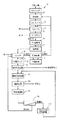
図1に示すように、本発明の実施形態に係る土壌浄化システムSにおいては、有害金属等(有害金属及び/又はその化合物)ないしはこれらのイオンで汚染された地盤の掘削等により採取された土壌(汚染土壌)が、投入ホッパ1に受け入れられる。なお、有害金属としては、例えばクロム、鉛、カドミウム、セレン、水銀、金属砒素などが挙げられる。そして、投入ホッパ1内の土壌は連続的又は間欠的に混合器2に投入され、混合器2に連続的に供給される洗浄水と混合される。ここで、土壌は、礫(例えば、粒径2〜75mm)と、砂(例えば、粒径0.075〜2mm)と、細粒分(例えば、粒径0.075mm以下)とを含み、場合によっては石(例えば、粒径75mm以上)を含むものである。 As shown in FIG. 1, in the soil purification system S according to the embodiment of the present invention, soil collected by excavating ground contaminated with harmful metals etc. (hazardous metals and / or compounds thereof) or these ions The (contaminated soil) is received in the input hopper 1. Examples of the harmful metals include chromium, lead, cadmium, selenium, mercury, metal arsenic and the like. Then, the soil in the charging hopper 1 is continuously or intermittently charged into the mixer 2 and mixed with the washing water continuously supplied to the mixer 2. Here, the soil includes a weir (for example, a particle size of 2 to 75 mm), sand (for example, a particle size of 0.075 to 2 mm), and a fine particle fraction (for example, a particle size of 0.075 mm or less) Some contain stones (eg, 75 mm or more in particle size).
混合器2で生成された土壌と洗浄水とを含む混合物(以下「土壌・水混合物」という。)は、湿式破砕機であるミルブレーカ3に移送される。ミルブレーカ3としては、例えばロッドミルを用いることができる。ロッドミルは、詳しくは図示していないが、ドラムの中に複数のロッド(例えば、10本の75mmφ×2mのスチールロッド)が配置された破砕装置であり、ドラムの回転によってロッドが互いに平行に転動して線接触し、その衝撃力、剪断力、摩擦力等により礫及び砂を(場合によっては石も)破砕して細粒分等の小径の土壌粒子を生成することができるものである。ミルブレーカ3として、ロッドミルのほかにボールミルなども用いることができる。なお、礫及び砂は、その一部が細粒分になるのであって、すべてが細粒分になる訳ではない。 A mixture containing soil and wash water generated by the mixer 2 (hereinafter referred to as "soil / water mixture") is transferred to a
かくして、ミルブレーカ3は、混合器2から排出された土壌・水混合物中の礫及び砂を(場合によっては石も)破砕して細粒分等の小径の土壌粒子を生成する。これにより、礫及び砂に吸着され(付着し)又は含まれていた有害金属等が水中に離脱する。このとき、基本的には(後記の鉄等による吸着はさておき)、水中に離脱した有害金属等は、礫及び砂にはほとんど吸着されず、ないしは付着せず、細粒分に集約して吸着され、ないしは付着する(例えば、非特許文献1参照)。 Thus, the
さらに、礫及び砂の内部に偏在又は点在していた鉄等(鉄及び/又は酸化鉄)の微小塊が表面に露出する多数の鉄系細粒分が生成される。一方、一般に鉄等は有害金属等を吸着する性質がある。このため、洗浄水中に存在する有害金属等ないしはこれらのイオンの一部が鉄系細粒分の鉄等の露出面に吸着され、ないしは付着する。その結果、鉄系細粒分の有害金属等の吸着量(付着量)は、非鉄系細粒分の有害金属等の吸着量(付着量)よりかなり多くなる。つまり、ミルブレーカ3から排出される細粒分は、有害金属等の吸着量(付着量)が多い鉄系細粒分と、有害金属等の吸着量(付着量)が少ない非鉄系細粒分とで構成される。なお、破砕以前から存在する鉄系細粒分も、非鉄系細粒分に比べてかなり多くの有害金属等を吸着しているのはもちろんである。 In addition, a large number of iron-based fine particles are generated in which micro-mass of iron or the like (iron and / or iron oxide) unevenly distributed or scattered in the straw and sand is exposed to the surface. On the other hand, iron and the like generally have the property of adsorbing harmful metals and the like. For this reason, some of the harmful metals and the like or these ions present in the wash water are adsorbed or attached to the exposed surface of the iron-based fine particles such as iron. As a result, the adsorption amount (adhesion amount) of harmful metals and the like of iron-based fine particles is considerably larger than the adsorption amount (adhesion amount) of harmful metals and the like of non-ferrous fine particles. That is, the fine particles discharged from the
このように有害金属等を吸着している鉄系細粒分は、後で説明するように、鉄分除去装置12によって除去される。一方、鉄等(鉄及び/又は酸化鉄)が有害金属等を吸着する性質を有することは一般に知られており、この性質を利用して、有害金属等を含むスラッジに鉄粉ないしは酸化鉄の粉末を添加することにより、スラッジから有害金属等を除去するようした「鉄粉法」が種々提案されている(例えば、特許文献3〜4、非特許文献2参照)。しかしながら、本発明のように、礫及び砂を破砕することにより、表面にフレッシュな(まだ有害金属等を吸着していない)鉄等の微小塊が露出した鉄系細粒分を生成し、これらの露出した鉄等の微小塊(鉄系細粒分)に有害金属等を吸着させるようにした有害金属等の処理手法は提案されていない。 The iron-based fine particles that adsorb the harmful metals and the like in this manner are removed by the
ミルブレーカ3から排出された土壌・水混合物はトロンメル4に導入される。トロンメル4は、詳しくは図示していないが、水を貯留することができる受槽と、水平面に対して傾斜して配置された略円筒形のドラムスクリーンとを有する篩分装置であって、ドラムスクリーンは、モータによりその中心軸(円筒の中心軸)まわりに回転することができるようになっている。また、ドラムスクリーン内に、洗浄水をスプレー状で噴射することができるようになっている。 The soil / water mixture discharged from the
トロンメル4の回転しているドラムスクリーンの内部を土壌・水混合物が流れる際に、ドラムスクリーンの網目より細かい土壌粒子は、洗浄水とともにドラムスクリーンの網目を通り抜け、ドラムスクリーン外に出て受槽内に入る。他方、ドラムスクリーンの網目より粗い土壌粒子は、ドラムスクリーンの網目を通り抜けることができないので、ドラムスクリーンの下側の開口端を経由して、ドラムスクリーン外に排出される。 As the soil-water mixture flows inside the rotating drum screen of Trommel 4, soil particles finer than the mesh of the drum screen pass through the mesh of the drum screen together with the washing water and go out of the drum screen to the inside of the receiving tank to go into. On the other hand, since soil particles coarser than the mesh of the drum screen can not pass through the mesh of the drum screen, they are discharged out of the drum screen via the lower open end of the drum screen.
このトロンメル4では、ドラムスクリーンの網目の分級径(目開き)は、粒径が2mm未満の土壌粒子、すなわち砂及び細粒分がドラムスクリーンの網目を通り抜けるように設定されている。したがって、このトロンメル4では、粒径が2mm以上の土壌粒子である礫が(場合によっては石も)土壌・水混合物から分離される。前記のとおり、水中に離脱した有害金属等は礫及び砂にはほとんど吸着されず、ないしは付着しないので、トロンメル4で分離された礫は清浄なものであり、例えばコンクリート用の骨材等として用いることができる。なお、トロンメル4のドラムスクリーンの網目の寸法(目開き)は前記のものに限定されるわけではなく、得ようとする土壌粒子の粒径に応じて、任意に設定することができるのはもちろんである。 In the trommel 4, the classification diameter (opening) of the mesh of the drum screen is set so that soil particles having a particle size of less than 2 mm, that is, sand and fine particles pass through the mesh of the drum screen. Therefore, in this trommel 4, a weir, which is a soil particle having a particle size of 2 mm or more (sometimes also a stone), is separated from the soil-water mixture. As mentioned above, since harmful metals and the like released in water are hardly adsorbed or attached to straw and sand, the straw separated by the trommel 4 is clean, and is used, for example, as an aggregate for concrete be able to. The mesh size (opening) of the drum screen of the trommel 4 is not limited to the above, and of course it can be set arbitrarily according to the particle size of the soil particles to be obtained. It is.
トロンメル4の受槽内に収容された粒径が2mm未満の土壌粒子、すなわち砂及び細粒分と洗浄水とを含む土壌・水混合物はサイクロン5(液体サイクロン)に導入される。サイクロン5は、詳しくは図示していないが、下方に向かって狭まる略円錐状のシリンダ内に土壌・水混合物をポンプで圧送して旋回流を生じさせ、これによって生じる遠心力を利用して、土壌・水混合物を、比較的粒径が小さい細粒分(例えば、粒径0.075mm未満)と水の混合物と、比較的粒径が大きい砂(例えば、粒径0.075mm以上)と水の混合物とに分離する。 Soil particles contained in the receiving tank of the trommel 4 and having a particle diameter of less than 2 mm, that is, a soil / water mixture containing sand and fine particles and washing water, are introduced into the cyclone 5 (hydrocyclone). Although not shown in detail, the
そして、細粒分と水の混合物(以下「細粒分含有水」という。)はサイクロン5の上端部から排出され、比較的粒径が大きい砂と水の混合物はサイクロン5の下端部から排出される。ここで、サイクロン5の下端部から排出された砂は、前記のとおり有害金属等をほとんど含んでいないので、水切りないしは乾燥処理を施して再生砂として使用される。他方、細粒分含有水はPH調整槽6に移送される。 Then, a mixture of fine particles and water (hereinafter referred to as “fine-grain-containing water”) is discharged from the upper end of the
PH調整槽6では、細粒分含有水のpHが、酸液(例えば、硫酸、塩酸)及びアルカリ液(例えば、水酸化ナトリウム水溶液)を用いて、ほぼ中性となるように調整される。なお、図示していないが、PH調整槽6では、細粒分含有水のpHは、pHメータ等を備えたpH自動制御装置により自動的に調整される。 In the PH adjustment tank 6, the pH of the fine particle-containing water is adjusted to be substantially neutral using an acid solution (for example, sulfuric acid, hydrochloric acid) and an alkali solution (for example, sodium hydroxide aqueous solution). Although not shown, in the pH adjustment tank 6, the pH of the fine particle-containing water is automatically adjusted by a pH automatic control device equipped with a pH meter or the like.
PH調整槽6でpHが調整された細粒分含有水は凝集槽7に導入される。凝集槽7では、細粒分含有水にポリ塩化アルミニウム水溶液(PAC)と、高分子凝集剤と、pH調整剤(酸性液又はアルカリ性液)とが添加される。これにより、凝集槽7内に非水溶性の金属水酸化物と細粒分とが混在する多数のフロックが生成される。 The fine particle-containing water whose pH has been adjusted in the PH adjustment tank 6 is introduced into the aggregation tank 7. In the coagulation tank 7, an aqueous solution of polyaluminum chloride (PAC), a polymer flocculant, and a pH adjuster (acidic solution or alkaline solution) are added to the fine particle-containing water. As a result, a large number of flocs in which the water-insoluble metal hydroxide and the fine particles are mixed are generated in the aggregation tank 7.
凝集槽7内の細粒分含有水(フロックを含む)はシックナ8に導入される。シックナ8は、詳しくは図示していないが、細粒分含有水がほぼ静止している状態で非水溶性のフロックないしは細粒分を重力により沈降させ、下部に位置するスラッジ層(例えば、固形分の比率が5〜10%)と、上部に位置しほとんどフロックないしは細粒分を含まない上澄水(洗浄水)とを形成する。なお、上澄水の表面に浮上油が浮遊している場合、この浮上油は、少量の上澄水をシックナ8の上部から溢流させることにより除去される。 Fine-grain-containing water (including floc) in the coagulation tank 7 is introduced into the thickener 8. The chicna 8 is not shown in detail, but the non-water-soluble floc or fines are caused to settle by gravity while the fines-containing water is almost stationary, and the sludge layer located at the lower part (for example, solid) (5 to 10%) and a supernatant (wash water) which is located on the top and contains almost no floc or fines. When floated oil floats on the surface of the supernatant water, the floated oil is removed by overflowing a small amount of supernatant water from the top of the thickener 8.
シックナ8内の上澄水は、洗浄水槽10に導入され、一時的に貯留される。洗浄水槽10が満杯になったときには予備水槽11が使用される。洗浄水層10ないしは予備水槽11に貯留されている洗浄水は、循環水として混合器2及びトロンメル4に供給される。なお、洗浄水槽10に貯留されている洗浄水が、蒸発等により減少したときには、適宜に水道水が補給される。他方、シックナ8の下部に沈殿ないしは滞留しているスラッジは、中間タンク9に移送され、一時的に貯留される。そして、中間タンク9内のスラッジは、連続的に鉄分除去装置12(12A、12B)に移送される。 Supernatant water in the chicna 8 is introduced into the washing water tank 10 and temporarily stored. When the washing water tank 10 is full, the
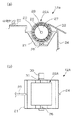
図2(a)及び図2(b)に示すように、1つの実施形態に係る鉄分除去装置12Aは、スラッジ槽21と、磁石装着ドラム22Aとを備えている。ここで、スラッジ槽21は、中間タンク9から管路23を介して移送されてくる細粒分(鉄系細粒分及び非鉄系細粒分)と水とからなるスラッジを受け入れて一時的に保留する。そして、スラッジ槽21内のスラッジは、後で説明するように鉄系細粒分が除去された後、管路24を介して細粒分洗浄装置13(図1参照)に移送される。なお、スラッジ槽21内には、細粒分の底部への沈殿を阻止するために攪拌機25が設けられている。 As shown in FIGS. 2A and 2B, the iron
磁石装着ドラム22Aは、回転シャフト26と、回転シャフト26に同軸に取り付けられた円筒状のドラム本体27と、ドラム本体27の円周部(外縁部)の内側に(例えば嵌め込みにより)ドラム円周方向に互いに隣り合って環状に装着ないしは配列された複数の永久磁石28と、環状に配列された永久磁石群の外周面を覆う円筒状カバー29とを備えている。ここで、磁石装着ドラム22Aないしはドラム本体27は、その回転中心軸が水平方向を向きかつドラム下部がスラッジ槽21内のスラッジに浸漬されるように配置されている。 The
複数の永久磁石28は、それぞれ、磁極がドラム径方向外方に向くように(外向き)配設されている。永久磁石28は、N極又はS極がすべて外向きとなるように配置してもよく、また、N極とS極が交互に外向きとなるように配置してもよい。円筒状カバー29は、厚さが比較的薄い(例えば、5〜10mm)軟磁性金属材料(例えば、鉄又は鉄合金)で形成するのが好ましいが、反磁性金属材料(例えば、銅もしくはアルミニウム又はこれらの合金)で形成してもよい。 The plurality of
回転シャフト26ひいてはドラム本体27は、モータ30(電動機)によって減速機31を介して回転駆動され、図2(a)中における位置関係において時計回り方向に緩速(例えば、0.5〜2.0r.p.m.)で回転する。そして、磁石装着ドラム22Aないしはドラム本体27がスラッジ槽21内のスラッジに浸漬されているときには、スラッジ中の鉄系細粒分が永久磁石28の磁力により円筒状カバー29の外周面に引き寄せられて吸着される。かくして、磁石装着ドラム22Aないしはドラム本体27がスラッジの外に出たときには、円筒状カバー29の外周面に、鉄系細粒分層が形成されている。円筒状カバー29の外周面に形成された鉄系細粒分層は、スクレーパ32によって掻き取られ、磁石装着ドラム22Aから除去される。なお、除去された鉄系細粒分は、例えば製鉄原料として用いることができる。 The
鉄系細粒分は、礫及び砂を湿式破砕機であるミルブレーカ3(図1参照)で破砕することにより生成されたもの、あるいは礫及び砂の破砕以前から存在するものであり、いずれもその表面に鉄等の微小塊が露出し、露出している鉄等の微小塊にはかなり多量の有害金属等が吸着されている。一般に、礫中及び砂中には、鉄等の小塊が偏在又は点在しており、このような小塊の割合は2〜5質量%程度である。このため、礫及び砂の破砕により生成された細粒分の一部は、表面にフレッシュな鉄等が露出する鉄系細粒分となる。 The iron-based fine particles are those produced by crushing straw and sand with the mill breaker 3 (see FIG. 1), which is a wet crusher, or those which exist before crushing of the straw and sand, both of which Micro-mass such as iron is exposed on the surface, and a considerable amount of harmful metals and the like are adsorbed on the micro-mass such as iron which is exposed. In general, small pieces of iron or the like are unevenly distributed or scattered in a gutter and sand, and the proportion of such small pieces is about 2 to 5% by mass. For this reason, a part of the fine particles generated by crushing of the straw and sand becomes an iron-based fine particle in which fresh iron and the like are exposed on the surface.
鉄は強磁性体(軟磁性体)であり、磁石に吸着される。また、土壌中に存在する鉄酸化物は、実質的に四酸化三鉄(Fe3O4)と、γ型三酸化二鉄(γ−Fe2O3)と、α型三酸化二鉄(α−Fe2O3)とからなり、四酸化三鉄及びγ型三酸化二鉄は強磁性体(軟磁性体)であり、磁石に吸着される。なお、α型三酸化二鉄は磁化せず磁石には吸着されない。このため、表面に鉄等の微小塊が露出している鉄系細粒分は、鉄、四酸化三鉄又はγ型三酸化二鉄の強磁性(軟磁性)により永久磁石28に引き付けられ、円筒状カバー29の外周面に吸着される。Iron is a ferromagnetic material (soft magnetic material) and is adsorbed to a magnet. In addition, iron oxides present in the soil substantially include triiron tetraoxide (Fe 3 O 4 ), γ-type diiron trioxide (γ-Fe 2 O 3 ), and α-type diiron trioxide ( Triiron tetraoxide and γ-type diiron trioxide, which are made of α-Fe 2 O 3 ), are ferromagnetic substances (soft magnetic substances) and are adsorbed to a magnet. The α-type diiron trioxide is not magnetized and is not adsorbed to the magnet. For this reason, the iron-based fine particle fraction in which the micromass such as iron is exposed on the surface is attracted to the
なお、本願発明者が、滋賀県大津市の株式会社山▲崎▼砂利商店途中工場の汚染土壌処理場において、2017年7月に複数回(10回)、ミルブレーカで礫及び砂を破砕して生成した細粒分と水の混合物であるスラッジ(細粒分1〜3質量%)について、直径約1mの磁石装着ドラム(永久磁石としてネオジム磁石を使用)を用いて鉄系細粒分の吸着実験を行ったところ、平均的にはスラッジ10m3あたり3.4kgの鉄系細粒分が採取された。In addition, the inventor of the present invention crushes gravel and sand with a mill breaker a plurality of times (ten times) in July 2017 at the contaminated soil treatment site of Yamazaki Co., Ltd., a gravel shop along the way in Otsu City, Shiga Prefecture. Of sludge (fine particle content 1 to 3% by mass), which is a mixture of fine particles and water produced, using a magnet-equipped drum with a diameter of about 1 m (using neodymium magnet as a permanent magnet) It was carried out adsorption experiment, the average ferrous fine fraction of 3.4kg per sludge 10 m 3 was taken.
礫及び砂をミルブレーカ3(図1参照)で破砕することにより生成された鉄系細粒分の表面に露出している鉄等の微小塊は、礫中又は砂中に偏在又は点在していた有害金属等を吸着していないフレッシュな鉄等の小塊から生じたものであり、破砕後に表面に露出してその周囲の洗浄水から有害金属等ないしはこれらのイオンを吸着する。かくして、ミルブレーカ3(図1参照)から排出され鉄分除去装置12Aに導入される細粒分は、有害金属等の吸着量が比較的(ないしはかなり)多い鉄系細粒分と、有害金属等の吸着量が比較的(ないしはかなり)少ない非鉄系細粒分とで構成される。 Micro-mass such as iron exposed on the surface of iron-based fine particles generated by crushing gravel and sand with mill breaker 3 (see FIG. 1) is unevenly distributed or scattered in the gravel or sand It is produced from small pieces of fresh iron or the like that does not adsorb harmful metals and the like, and is exposed to the surface after crushing and adsorbs harmful metals and the like from washing water around them. Thus, the fine particles discharged from the mill breaker 3 (see FIG. 1) and introduced into the
そして、前記のとおり、鉄分除去装置12Aではスラッジから鉄系細粒分が除去されるので、鉄分除去装置12Aから排出されるスラッジに含まれる細粒分は、有害金属等の吸着量が比較的(ないしはかなり)少ない非鉄系細粒分が大半となる。したがって、土壌浄化システムSに導入された汚染土壌に含まれていた有害金属等の一部ないしはかなりの部分は、鉄分除去装置12Aによって除去される。なお、スラッジ槽21内のスラッジの水素指数をpH4〜6の範囲内に調整すれば、鉄系細粒分の有害金属等の吸着量が若干増加する。この場合、スラッジ槽21から排出されたスラッジを中和するのが好ましい。 And, as described above, since the iron-based fine particles are removed from the sludge in the iron-removing
後で説明するように、鉄分除去装置12Aから排出されたスラッジないしは細粒分に対して、細粒分洗浄装置13(図1参照)でキレート剤によるキレート洗浄処理が行われ、かつキレート剤再生装置17(図1参照)で固相吸着材によりキレート剤の再生処理が行われるが、前記のとおり鉄分除去装置12Aでスラッジ中の有害金属等が低減されるので、細粒分(スラッジ)のキレート洗浄処理及びキレート剤の再生処理に対する有害金属等の負荷が軽減される。このため、土壌浄化システムSにおけるキレート剤及び固相吸着材の必要量ないしは使用量を低減することができ、土壌の処理コストを低減することができる。つまり、鉄分除去装置12Aは、細粒分洗浄装置13ないしはキレート剤再生装置17への有害金属等の負荷を軽減する前処理装置ないしは予備処理装置として機能する。 As described later, the sludge or fine particles discharged from the
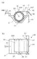
以下、図3(a)、(b)を参照しつつ、図2(a)、(b)に示す鉄分除去装置12Aとは構成が異なるもう1つの鉄分除去装置12Bの構成及び機能を説明する。ただし、図3(a)、(b)に示す鉄分除去装置12Bの構成要素の大部分は、図2(a)、(b)に示す鉄分除去装置12Aの構成要素と共通であるので、説明の重複を避けるため、以下では主として鉄分除去装置12Aと異なる点を説明する。なお、図3(a)、(b)に示す鉄分除去装置12Bの構成要素において、図2(a)、(b)に示す鉄分除去装置12Aの構成要素と共通なものには、同一の参照番号が付されている。 Hereinafter, the configuration and function of another
図3(a)、(b)に示す鉄分除去装置12Bでは、スラッジ槽21の上方に、磁石装着ドラム22Bないしはドラム本体27とは別に円柱形の駆動ローラ41が設けられ、この駆動ローラ41は駆動シャフト42に同軸に取り付けられている。駆動ローラ41及び駆動シャフト42は、その回転中心軸がドラム本体27の回転中心軸と平行となるように配置され、モータ30によって減速機31を介して回転駆動されるようになっている。駆動ローラ41はドラム本体27よりも小径(例えば、1/5〜1/10)である。 In the iron
ドラム本体27には、図2(a)に示す鉄分除去装置12Aと同様の仕様で複数の永久磁石28が装着ないしは配設されている。磁石装着ドラム22Bの回転シャフト26は、スラッジ槽21に固定された軸受により従動回転自在に支持されている。なお、鉄分除去装置12Aと同様の円筒状カバーを設けてもよい。そして、円周部の内側に複数の永久磁石28が環状に装着ないしは配列されたドラム本体27と駆動ローラ41とにわたって、軟磁性金属材料(例えば、鉄又は鉄合金)からなる無端ベルト43(例えば、スチールベルト)が巻き掛けられている。なお、無端ベルト43を反磁性金属材料(例えば、銅もしくはアルミニウム又はこれらの合金)で形成してもよい。 A plurality of
駆動ローラ41が、モータ30によって減速機31を介して、図3(a)中における位置関係において時計回り方向に回転駆動されると、ドラム本体27ないしは磁石装着ドラム22Bは時計回り方向に従動回転し、無端ベルト43は駆動ローラ41とドラム本体27との間を時計回り方向に周回走行する。なお、モータ30ないしは駆動ローラ41の回転数は、ドラム本体27が緩速(例えば、0.5〜2.0r.p.m.)で回転するように設定されている。 When the
駆動ローラ41とドラム本体27との間を、図3(a)中における位置関係において時計回り方向に周回走行する無端ベルト43が、ドラム本体27の円周面の内側に環状に配列された永久磁石群の外周面に当接し、かつスラッジ槽21内のスラッジに浸漬されているときには、スラッジ中の鉄系細粒分が永久磁石28の磁力により無端ベルト43の外面に引き寄せられて吸着される。かくして、無端ベルト43がスラッジの外に出たときには、0無端ベルト43の外面に鉄系細粒分層が形成されている。無端ベルト43の外面に形成された鉄系細粒分層は、駆動ローラ41近傍でスクレーパ32によって掻き取られ、無端ベルト43から除去される。 An
図3(a)、(b)に示す鉄分除去装置12Bにおいても、図2(a)、(b)に示す鉄分除去装置12Aと同様に、スラッジから鉄系細粒分が除去されるので、鉄分除去装置12Bから排出されるスラッジに含まれる細粒分は、有害金属等の吸着量が比較的(ないしはかなり)少ない非鉄系細粒分が大半となる。したがって、土壌浄化システムSに導入された汚染土壌に含まれていた有害金属等の一部ないしはかなりの部分は、鉄分除去装置12Bによって除去される。 Also in the iron
鉄分除去装置12(12A、12B)から排出されたスラッジは、細粒分洗浄装置13(図1参照)に導入される。細粒分洗浄装置13は、鉄分除去装置12(12A、12B)から排出された非鉄系細粒分と洗浄水とを含むスラッジと、後で説明するキレート剤再生装置17(図1参照)から供給されるキレート剤と水とを含むキレート洗浄液とを受け入れ、これらを混合・攪拌して細粒分スラリーを生成し、予め設定された滞留時間(例えば、0.5〜2時間)を確保するようにおおむねプラグフロー(栓流)で連続的に流動させることにより、細粒分に付着(吸着)している有害金属等ないしはこれらのイオンをキレート剤に捕捉させる。これにより、細粒分スラリー中の細粒分の表面に吸着(付着)されている有害金属等が除去される。細粒分洗浄装置13に供給するスラッジの流量とキレート洗浄液の流量の比は、例えば1:1に設定される。 The sludge discharged from the iron content removing device 12 (12A, 12B) is introduced into the fine particle content cleaning device 13 (see FIG. 1). The fine particle
キレート洗浄液に用いられるキレート剤としては、例えば、EDTA(エチレンジアミン四酢酸)、あるいはHIDS(3−ヒドロキシ−2,2’−イミノジコハク酸)、IDS(2,2’−イミノジコハク酸)、MGDA(メチルグリシン二酢酸)、EDDS(エチレンジアミンジ酢酸)又はGLDA(L−グルタミン酸ジ酢酸)のナトリウム塩などが挙げられる。これらのキレート剤は、いずれも細粒分スラリーないしは細粒分に含まれている有害金属等を有効に捕捉する(キレートする)ことができものである。なお、細粒分に含まれる有害金属等の種類に応じて、その処理に適したキレート剤が選択され、又は複数種のキレート剤が用いられるのはもちろんである。 As a chelating agent used for the chelate washing solution, for example, EDTA (ethylenediaminetetraacetic acid), or HIDS (3-hydroxy-2,2'-iminodisuccinic acid), IDS (2,2'-iminodisuccinic acid), MGDA (methylglycine) And sodium salts of EDDS (ethylenediaminediacetic acid) or GLDA (L-glutamic acid diacetic acid). Any of these chelating agents can effectively capture (chelate) harmful metals and the like contained in the fine particle slurry or fine particle fraction. Of course, a chelating agent suitable for the treatment is selected or plural kinds of chelating agents are used according to the type of harmful metal and the like contained in the fine particle fraction.
以下、図4(a)〜(c)を参照しつつ、細粒分洗浄装置13の具体的な構成及び機能を説明する。細粒分洗浄装置13は、4つの平板状の仕切り壁51〜54で仕切ることにより形成された互いに平行に伸びる5つの細長い直方体状ないしは角柱状のスラリー通路55〜59を備えた貯槽50を有している。貯槽50は、例えば地上に設置した鉄製の直方体状の角型タンクであってもよく、またコンクリート製の直方体状のピットであってもよい。また、仕切り壁51〜54は、例えば複数の鉄板又はプラスチック板をスラリー通路の伸びる方向に連結することにより形成したものであってもよい。 Hereinafter, the specific configuration and function of the fine particle
スラリー通路55〜59において隣り合う2つのスラリー通路はスラリー通路長手方向(図4(a)、(b)における位置関係では左右方向)の一端の連通部(図4(a)中に4つの曲線状の矢印で示された部位)で互いに連通している。すなわち、これらの連通部には仕切り壁51〜54が存在せず、隣り合うスラリー通路同士が連通している。 The two slurry channels adjacent in the
各スラリー通路55〜59の底部には、それぞれ、細粒分スラリー中に空気を放出して細粒分スラリーを攪拌する空気放出管61〜65が配設されている。各空気放出管61〜65はスラリー通路長手方向に伸び、周壁の底部(下側)においてスラリー通路長手方向に並ぶ複数の空気放出孔が形成された多孔管であり、その中空部は、詳しくは図示していないが、圧縮空気を供給するコンプレッサないしは送風機に接続されている。空気放出管61〜65に加圧された空気が供給されたときには、この空気が空気放出孔から気泡となって細粒分スラリー中に放出されて浮上し、この気泡によって細粒分スラリーが攪拌される。 At the bottom of each of the
図4(c)は、細粒分スラリーの流れ方向(図4(a)中に曲線状の矢印及び直線状の矢印で示す方向)にみて最も上流側のスラリー通路55の断面を示している。図4(c)から明らかなとおり、空気放出管61は、スラリー通路55の一方の側面の近傍においてスラリー通路底部近傍に配置されている。このため、空気放出管61から放出された気泡はこの側面の近傍で上昇する。その結果、スラリー通路55内には、スラリー通路長手方向と垂直な平面内において矢印Pで示す方向に流れる循環流が形成され、細粒分スラリーが攪拌される。貯槽50及び各スラリー通路55〜59の形状、寸法、容量等、並びに空気放出管61〜65への加圧空気の供給量等は、細粒分洗浄装置13において予め設定される細粒分スラリーの、含水率、流量、滞留時間、流速、流れの乱流度(例えば、レイノルズ数)等に対応して好ましく設定される。 FIG. 4C shows a cross section of the most
再び図1に示すように、細粒分洗浄装置13から排出された細粒分スラリーは濾過装置14に移送される。濾過装置14は、細粒分スラリーを濾過し、含水率が30〜40パーセントの濾過ケークと濾液とを生成する。なお、濾過装置14としては、フィルタプレスや真空濾過機などを用いることができる。濾過装置14から排出された濾過ケーク(細粒分)は有害金属等をほとんど含まないので、例えば農業用の培土として利用され、あるいは埋立て等により処分される。 As shown in FIG. 1 again, the fine particle slurry discharged from the fine
濾過装置14から排出された濾液すなわちキレート洗浄液は、清澄濾過器15(例えば、砂濾過器)で懸濁物質ないしは浮遊物質(SS)が除去された後、逆浸透膜分離装置16に移送される。詳しくは図示していないが、逆浸透膜分離装置16は、清澄濾過器15から排出されたキレート洗浄液を受け入れ、高圧ポンプで加圧した上で、逆浸透膜により、キレート剤が濃縮された濃縮水と、キレート剤を含まない透過水とに分離する。 The filtrate or chelate washing solution discharged from the
逆浸透膜分離装置16の逆浸透膜としては、例えばポリエステル不織布(厚さ100〜120μm)の表面に、ポリスルホン支持層と架橋芳香族ポリアミド緻密層とが積層されてなる三層構造のものなどを用いることができる。なお、架橋芳香族ポリアミド緻密層は、孔径がおおむね0.5〜1.5nmである多数の細孔を有し、水は透過させるがキレート剤は透過させない非常に薄い(例えば、0.2〜0.25μm)半透膜である。また、ポリスルホン支持層は、非常に薄い架橋芳香族ポリアミド緻密層を支持ないしは保護してその破損を防止するための比較的厚い(例えば、40〜50μm)多孔質膜である。 The reverse osmosis membrane of the reverse osmosis
逆浸透膜分離装置16はスパイラル型のものであり、スパイラル状に巻かれた逆浸透膜が円筒状の容器内に収容されてなる逆浸透膜エレメントを複数有している。各逆浸透膜エレメントは、例えば全長を1〜2m程度とし、外径を0.2〜0.4m程度とするのが実用的である。例えば、全長が約1mであり、外径が約0.2mである市販のこの種の逆浸透膜エレメント(例えば、岐阜県中津川市の株式会社オーセンテック製)における逆浸透膜の有効膜面積は約40m2である。この逆浸透膜エレメントの場合、キレート剤濃度が1質量%程度のキレート洗浄液を1MPa程度の圧力で供給するときの、キレート洗浄液の処理量は約1.5m3/hrと推定される。したがって、例えば毎時60m3のキレート洗浄液を処理する場合は、この逆浸透膜エレメントを40本並列に接続すればよい。The reverse osmosis
逆浸透膜分離装置16は連続式であり、キレート洗浄液の供給量及び供給圧力(操作圧力)、濃縮水及び透過水の排出量、濃縮水のキレート剤濃縮比等の運転条件は、細粒分洗浄装置13に供給すべきキレート洗浄液の量及びキレート剤濃度に応じて適切に設定される。例えば、細粒分洗浄装置13に供給するスラッジの流量とキレート洗浄液の流量の比を1:1に設定し、細粒分洗浄装置13における細粒分スラリーのキレート剤濃度を1質量%に設定した場合、逆浸透膜分離装置16はキレート洗浄液の供給量の50%程度の透過水(キレート剤濃度0)と50%程度の濃縮水(キレート剤濃度2質量%程度)とが生成されるように設定される。したがって、細粒分洗浄装置13では、キレート剤を含まないスラッジとキレート剤濃度が2質量%程度のキレート洗浄液とが1:1で混合され、細粒分洗浄装置13におけるキレート剤濃度は1質量%程度に維持される。 The reverse osmosis
逆浸透膜分離装置16から排出された濃縮水すなわちキレート洗浄液は、キレート剤再生装置17に導入されて再生される。キレート剤再生装置17は、キレート剤よりも錯生成力が高くキレート洗浄液と接触したときにキレート洗浄液中の有害金属等を吸着又は抽出する固相吸着材又は該固相吸着材が固定された小片ないしは粒状物を有し、キレート洗浄液中のキレート剤から有害金属等を除去し、キレート洗浄液を再生する。 The concentrated water, that is, the chelate washing solution discharged from the reverse osmosis
固相吸着材は、担体に環状分子を担持させ、環状分子にキレート配位子を修飾した配位結合及び水素結合による多点相互作用を有するとともに有害金属等のイオンを選択的に取り込むものである。これにより、キレート剤に捕捉されている有害金属等はキレート剤から離脱させられ、固相吸着材に吸着又は抽出される。これにより、キレート洗浄液(キレート剤)から有害金属等が除去・回収され、キレート洗浄液(キレート剤)は再び有害金属等を捕捉することができる状態となる。 The solid phase adsorbent is a carrier having a cyclic molecule supported on the carrier, a coordination with a chelate ligand modified to the cyclic molecule and multipoint interaction by hydrogen bond and selectively incorporating ions such as harmful metals. is there. Thereby, harmful metals and the like captured by the chelating agent are released from the chelating agent and adsorbed or extracted by the solid phase adsorbent. As a result, harmful metals and the like are removed and recovered from the chelate washing liquid (chelating agent), and the chelate washing liquid (chelating agent) is in a state capable of capturing harmful metals and the like again.
キレート剤より錯生成力が高い固相吸着材は、例えばゲル等の固体状のものであり、一般に、金属を捕捉しているキレート剤を含む水溶液と接触したときに、キレート剤と配位結合している金属イオンをキレート剤から離脱させて該固相吸着材に移動させることができる程度の共有結合以外の強い結合力を有しているものである。このような固相吸着材は、例えばキレート剤としてEDTA(エチレンジアミン四酢酸)を用いる場合、濃度が10mM/lであるEDTA水溶液から、ほぼ100%の金属イオンを回収することができる強い結合力を有するものである。 Solid phase adsorbents having higher complexing power than chelating agents are in solid form such as, for example, a gel, and generally, when contacted with an aqueous solution containing a chelating agent capturing a metal, coordination bond with the chelating agent The metal ion has a strong avidity other than the degree of covalent bonding that can release the metal ion from the chelating agent and transfer it to the solid phase adsorbent. Such a solid phase adsorbent, for example, when using EDTA (ethylenediaminetetraacetic acid) as a chelating agent, has a strong binding ability to recover almost 100% of metal ions from an aqueous solution of EDTA having a concentration of 10 mM / l. It is possessed.
このような固相吸着材としては、例えばシリカゲルや樹脂等の担体に環状分子を密に担持させ、この環状分子にキレート配位子を修飾させたものなどが挙げられる。このような固相吸着材を用いる場合、隣り合う環状分子及びキレート配位子により、配位結合、水素結合などの複数の様々な結合や相互作用が生じて多点相互作用が生じ、金属イオンに対してキレート剤よりも強い化学結合が生じるとともに環状分子の性状により金属イオンを選択的に取り込むことができる。 As such a solid phase adsorbent, for example, a solid support of a cyclic molecule on a carrier such as silica gel or resin, and a modification of a chelate ligand to this cyclic molecule, and the like can be mentioned. When such a solid phase adsorbent is used, a plurality of various bonds and interactions such as coordination bonds and hydrogen bonds are caused by adjacent cyclic molecules and chelate ligands, resulting in multipoint interaction and metal ion On the other hand, stronger chemical bonds occur than chelating agents, and metal ions can be selectively incorporated by the nature of cyclic molecules.
以下、図5を参照しつキレート剤再生装置17の具体的な構成及び機能を説明する。キレート剤再生装置17には、その内部に固相吸着材粒子、又は固相吸着材が固定された充填物(パッキング)が充填された充填塔70が設けられている。また、キレート剤再生装置17には、再生すべきキレート洗浄液(濃縮水)を貯留する中間貯槽71と、再生されたキレート洗浄液を貯留する洗浄液貯槽72と、酸液を貯留する酸液貯槽73と、水を貯留する水貯槽74とが設けられている。 Hereinafter, the specific configuration and function of the chelating
中間貯槽71には、逆浸透膜分離装置16から排出された濃縮水すなわちキレート洗浄液が一時的に貯留される。そして、キレート洗浄液を再生するときに、中間貯槽71に貯留されたキレート洗浄液を充填塔70に移送する一方、充填塔70で再生されたキレート洗浄液を洗浄液貯槽72に移送するためのポンプ76及び一連の管路77〜80が設けられている。また、洗浄液貯槽72に貯留されたキレート洗浄液を細粒分洗浄装置13(図1参照)に供給するためのポンプ81及び管路82が設けられている。 In the
さらに、キレート剤再生装置17には、固相吸着材を再生する際に、酸液貯槽73に貯留された酸液を充填塔70に移送する一方、充填塔70から排出された酸液を酸液貯槽73に戻すためのポンプ83及び複数の管路84、85が設けられている。また、キレート剤再生装置17には、酸液で再生された固相吸着材を水洗する際に、水貯槽74に貯留された水を充填塔70に移送する一方、充填塔70から排出された水を水貯槽74に戻すためのポンプ86及び複数の管路87、88が設けられている。 Further, when the solid phase adsorbent is regenerated to the chelating
充填塔70にキレート洗浄液、酸液又は水を移送するための管路77、78、84、87には、それぞれ、対応する管路を開閉するバルブ91、92、93、94が介設されている。他方、充填塔70からキレート洗浄液、酸液又は水を排出するための管路79、80、85、88には、それぞれ、対応する管路を開閉するバルブ95、96、97、98が介設されている。これらのバルブ91〜98の開閉状態を切り換えることにより、充填塔70に対して、キレート洗浄液、酸液又は水のいずれかを給排することができる。なお、これらのバルブ91〜98の開閉は、図示していないコントローラによって自動的に制御される。
以下、キレート剤再生装置17の運転手法の一例を説明する。キレート洗浄液(キレート剤)を再生する際には、管路77〜80に介設されたバルブ91、92、95、96が開かれる一方、他のバルブ93、94、97、98が閉じられ、ポンプ76が運転される。これにより、中間貯槽72内のキレート洗浄液が、洗浄液再生装置35内を流通して洗浄液貯槽36に移送される。 Hereinafter, an example of the operation method of the chelating
充填塔70内では、有害金属等を捕捉しているキレート剤を含むキレート洗浄液が固相吸着材(固相吸着材粒子)と接触させられる。その結果、キレート剤に捕捉されている有害金属等がキレート剤から離脱させられ、固相吸着材に吸着ないしは抽出される。これにより、キレート洗浄液から有害金属等が除去・回収され、キレート剤は再び有害金属等を捕捉することができる状態となり、キレート洗浄液は再生される。 In the packed
キレート洗浄液の再生に伴って、固相吸着材における有害金属等の吸着量は経時的に増加してゆくが、固相吸着材の吸着能力には上限がある。このため、固相吸着材における有害金属等の吸着量が飽和状態ないしはその近傍に達したときには、固相吸着材は再生される。すなわち、キレート洗浄液が排除された状態で充填塔70内に酸液を流し、固相吸着材に吸着された有害金属等を酸液により除去して固相吸着材を再生する。かくして、有害金属等が酸液によって回収される一方、固相吸着材は再生されて再び有害金属等ないしはこれらのイオンを吸着又は抽出することが可能な状態となる While the amount of adsorption of harmful metals and the like in the solid phase adsorbent increases with the regeneration of the chelate washing solution, the adsorption capacity of the solid phase adsorbent has an upper limit. For this reason, when the adsorption amount of harmful metals and the like in the solid phase adsorbent reaches a saturated state or in the vicinity thereof, the solid phase adsorbent is regenerated. That is, the acid solution is flowed into the packed
充填塔70内の固相吸着材を酸液で再生する際には、管路84、78、79、85に介設されたバルブ93、92、95、97が開かれる一方、他のバルブ91、94、96、98が閉じられ、ポンプ83が運転される。これにより、酸液貯槽73内の酸液が、充填塔70内を流通して酸液貯槽73に還流する。固相吸着材の有害金属吸着量が飽和状態ないしはその近傍に達したか否かは、充填塔70から排出されたキレート洗浄液中の有害金属等の含有量を検出することにより判定することができる。 When the solid phase adsorbent in the packed
酸液による固相吸着材の再生が終了した後に固相吸着材を水洗する際には、管路87、78、79、88に介設されたバルブ94、92、95、98が開かれる一方、他のバルブ91、93、96、97が閉じられ、ポンプ86が運転される。これにより、水貯槽74内の水が、充填塔70内を流通して水貯槽74に還流する。水は、水貯槽74と充填塔70との間を循環して流れる。その際、充填塔70内の固相吸着材は水と接触し、固相吸着材に付着している酸液が洗浄される。この後、キレート洗浄液の再生が再開される。 When the solid phase adsorbent is washed with water after the regeneration of the solid phase adsorbent by the acid solution is finished, the
このように再生されたキレート洗浄液は、洗浄液貯槽72に一時的に貯留された後、細粒分洗浄装置13に供給される。つまり、キレート洗浄液は、細粒分の浄化とキレート剤の再生とを繰り返しつつ循環する。なお、キレート剤の目減り分は適宜に補充される。 The chelate washing solution thus regenerated is temporarily stored in the washing
以上、本発明に係る土壌浄化システムSによれば、清浄で再利用可能な礫、砂及び細粒分を得ることができる。また、鉄分除去装置12(12A、12B)から排出されるスラッジの有害金属等の含有率を低下させることができるので、細粒分洗浄装置13に対する有害金属等の負荷と、キレート剤再生装置17に対する有害金属等の負荷とを軽減することができ、キレート剤及び固相吸着材の必要量ないしは使用量を低減することができ、土壌の処理コストを低減することができる。なお、鉄分除去装置12(12A、12B)は、物理的な処理を施す簡素な機械構造のものであり、格別の化学薬品を使用しないので、その運転コストは非常に低い。 As described above, according to the soil remediation system S according to the present invention, clean and reusable straw, sand and fines can be obtained. Moreover, since the content rate of harmful metals and the like of the sludge discharged from the iron content removing device 12 (12A, 12B) can be reduced, the load of the harmful metals and the like on the fine
S 土壌浄化システム、1 投入ホッパ、2 混合器、3 ミルブレーカ(湿式破砕機)、4 トロンメル、5 サイクロン、6 PH調整槽、7 凝集槽、8 シックナ、9 中間タンク、10 洗浄水槽、11 予備水槽、12 鉄分除去装置、12A 鉄分除去装置、12B 鉄分除去装置、13 細粒分洗浄装置、14 濾過装置、15 清澄濾過器、16 逆浸透膜分離装置、17 キレート剤再生装置、21 スラッジ槽、22A 磁石装着ドラム、22B 磁石装着ドラム、23 管路、24 管路、25 攪拌機、26 回転シャフト、27 ドラム本体、28 永久磁石、29 円筒状カバー、30 モータ、31 減速機、32 スクレーパ、41 駆動ローラ、42 駆動シャフト、43 無端ベルト、50 貯槽、51〜54 仕切り壁、55〜59 スラリー通路、61〜65 空気放出管、70 充填塔、71 中間貯槽、72 洗浄水槽、73 酸液貯槽、74 水貯槽、76 ポンプ、77〜80 管路、81 ポンプ、82 管路、83 ポンプ、84 管路、85 管路、86 ポンプ、87 管路、88 管路、91〜98 バルブ。 S Soil remediation system, 1 input hopper, 2 mixer, 3 mill breaker (wet crusher), 4 trommel, 5 cyclone, 6 PH adjustment tank, 7 aggregation tank, 8 chicna, 9 intermediate tank, 10 washing water tank, 11 spare Water tank, 12 iron removing device, 12A iron removing device, 12B iron removing device, 13 fine particle washing device, 14 filtration device, 15 clarifying filter, 16 reverse osmosis membrane separation device, 17 chelating agent regeneration device, 21 sludge tank, 22A magnet mounting drum, 22B magnet mounting drum, 23 pipelines, 24 pipelines, 25 stirrers, 26 rotary shafts, 27 drum bodies, 28 permanent magnets, 29 cylindrical covers, 30 motors, 31 speed reducers, 32 scrapers, 41 drives Rollers, 42 drive shafts, 43 endless belts, 50 reservoirs, 51 to 54 partition walls, 55 -59 slurry passage, 61-65 air discharge pipe, 70 packed tower, 71 intermediate storage tank, 72 washing water tank, 73 acid liquid storage tank, 74 water storage tank, 76 pump, 77-80 pipeline, 81 pump, 82 pipeline, 83 Pump, 84 lines, 85 lines, 86 pumps, 87 lines, 88 lines, 91-98 valves.
Claims (3)
前記土壌浄化システムに導入された土壌と洗浄水とを混合する混合器と、
前記混合器から排出された土壌と洗浄水とを含む混合物中の礫及び砂を破砕することにより、礫及び砂の内部に偏在又は点在していた鉄又は鉄酸化物が表面に露出する鉄系細粒分を生成し、鉄系細粒分の表面に露出している鉄又は鉄酸化物に有害金属又はその化合物を吸着させる湿式破砕機と、
前記湿式破砕機から排出された、礫と砂と細粒分と洗浄水とを含む混合物から礫を分離するトロンメルと、
前記トロンメルから排出された砂と細粒分と洗浄水とを含む混合物から砂を分離する液体サイクロンと、
前記液体サイクロンから排出された細粒分と洗浄水とを含む混合物を、沈降分離により、上澄水と、細粒分と洗浄水とを含むスラッジとに分離するシックナと、
前記シックナから排出されたスラッジから、鉄系細粒分を磁力で吸着して除去することにより、スラッジの有害金属又はその化合物の含有率を低下させる鉄分除去装置と、
前記鉄分除去装置から排出されたスラッジと、キレート剤及び水を含むキレート洗浄液とを混合して細粒分スラリーを生成し、該細粒分スラリーを予め設定された滞留時間を確保するように流動させることにより、細粒分に付着している有害金属又はその化合物をキレート剤に捕捉させる細粒分洗浄装置と、
前記細粒分洗浄装置から排出された細粒分スラリーを濾過して、濾液と濾過ケークとを生成する濾過装置と、
前記濾過装置から排出された濾液を、逆浸透膜により、キレート剤が濃縮された濃縮水とキレート剤を含まない透過水とに分離する逆浸透膜分離装置と、
前記逆浸透膜分離装置から排出された濃縮水を受け入れ、キレート剤よりも錯生成力が高く濃縮水と接触したときに該濃縮水中の有害金属又はその化合物を吸着する固相吸着材により、濃縮水中のキレート剤から有害金属又はその化合物を除去して該濃縮液を前記キレート洗浄液として前記細粒分洗浄装置に供給するキレート剤再生装置と、
前記逆浸透膜分離装置から排出された透過水を前記シックナに移迭する透過水移送手段とを備えていて、
前記鉄分除去装置は、
前記シックナから排出されたスラッジを保留するスラッジ槽と、
ドラム状に形成され、ドラム中心軸が水平方向を向きかつドラム下部が前記スラッジ槽内のスラッジに浸漬されるように配置され、ドラム円周面の内側に複数の永久磁石がドラム径方向外方に磁極が向くようにドラム円周方向に並んで装着されている磁石装着ドラムと、
前記磁石装着ドラムをドラム中心軸まわりに回転させるドラム回転機構とを有することを特徴とする土壌浄化システム。What is claimed is: 1. A soil remediation system for remediation of soil contaminated with harmful metals or their compounds, comprising gravel, sand and fine particles,
A mixer for mixing the soil introduced into the soil remediation system with washing water;
Iron or iron oxide that is unevenly distributed or scattered inside the gravel and sand by crushing the gravel and sand in the mixture containing the soil and the washing water discharged from the mixer A wet crusher that produces a fine particulate component and adsorbs a harmful metal or its compound to iron or iron oxide exposed on the surface of the fine particulate iron component;
A trommel that separates the straw from the mixture containing the straw, sand, fine particles and washing water, which is discharged from the wet crusher;
A hydrocyclone separating sand from a mixture comprising sand, fines and wash water discharged from the trommel;
A thickener which separates a mixture containing fine particles and wash water discharged from the hydrocyclone into supernatant water and sludge containing fine particles and wash water by sedimentation separation;
An iron removing device for reducing the content of harmful metals or compounds thereof by removing magnetic fine particles from the sludge discharged from the thickener by magnetic attraction;
The sludge discharged from the iron removing device is mixed with a chelate washing solution containing a chelating agent and water to form a fine particle slurry, and the fine particle slurry is flowed to secure a preset residence time. A fine particle washing apparatus for causing a chelating agent to trap harmful metals or compounds thereof adhering to fine particles by
A filtering device for filtering the fine particle slurry discharged from the fine particle washing device to form a filtrate and a filter cake;
A reverse osmosis membrane separation device that separates the filtrate discharged from the filtration device into concentrated water concentrated with a chelating agent and permeated water containing no chelating agent by a reverse osmosis membrane;
A solid phase adsorbent that receives concentrated water discharged from the reverse osmosis membrane separation device and has a higher complexing power than a chelating agent and adsorbs harmful metals or compounds thereof in the concentrated water when contacted with the concentrated water A chelating agent regenerating apparatus for removing harmful metals or compounds thereof from a chelating agent in water and supplying the concentrate as the chelating washing solution to the fine particle size washing apparatus;
A permeated water transfer means for transferring the permeated water discharged from the reverse osmosis membrane separation device to the thickener;
The iron removal device is
A sludge tank for retaining sludge discharged from the thickener;
The drum is formed in a drum shape, the drum central axis is directed in the horizontal direction, and the lower portion of the drum is disposed so as to be immersed in the sludge in the sludge tank, and a plurality of permanent magnets are radially outward in the drum circumferential surface. Magnet mounted drums, which are mounted side by side in the circumferential direction of the drum, with the magnetic poles facing
And a drum rotation mechanism for rotating the magnet mounting drum around a drum center axis.
Priority Applications (1)
| Application Number | Priority Date | Filing Date | Title |
|---|---|---|---|
| JP2017254858A JP6358519B1 (en) | 2017-12-12 | 2017-12-12 | Soil purification system |
Applications Claiming Priority (1)
| Application Number | Priority Date | Filing Date | Title |
|---|---|---|---|
| JP2017254858A JP6358519B1 (en) | 2017-12-12 | 2017-12-12 | Soil purification system |
Publications (2)
| Publication Number | Publication Date |
|---|---|
| JP6358519B1 JP6358519B1 (en) | 2018-07-18 |
| JP2019103997A true JP2019103997A (en) | 2019-06-27 |
Family
ID=62904953
Family Applications (1)
| Application Number | Title | Priority Date | Filing Date |
|---|---|---|---|
| JP2017254858A Active JP6358519B1 (en) | 2017-12-12 | 2017-12-12 | Soil purification system |
Country Status (1)
| Country | Link |
|---|---|
| JP (1) | JP6358519B1 (en) |
Cited By (1)
| Publication number | Priority date | Publication date | Assignee | Title |
|---|---|---|---|---|
| CN110293122A (en) * | 2019-08-09 | 2019-10-01 | 周成宗 | One kind containing metal impurities soil remediation method |
Families Citing this family (13)
| Publication number | Priority date | Publication date | Assignee | Title |
|---|---|---|---|---|
| JP6447855B1 (en) * | 2018-07-17 | 2019-01-09 | 公信 山▲崎▼ | Soil purification system |
| JP6447854B1 (en) * | 2018-07-17 | 2019-01-09 | 公信 山▲崎▼ | Soil purification system |
| JP6447856B1 (en) * | 2018-07-17 | 2019-01-09 | 公信 山▲崎▼ | Soil purification system |
| JP6451972B1 (en) * | 2018-07-17 | 2019-01-16 | 公信 山▲崎▼ | Soil purification system |
| JP6447857B1 (en) * | 2018-07-17 | 2019-01-09 | 公信 山▲崎▼ | Soil purification system |
| JP6458976B1 (en) * | 2018-07-17 | 2019-01-30 | 公信 山▲崎▼ | Soil purification system |
| JP6458975B1 (en) * | 2018-07-17 | 2019-01-30 | 公信 山▲崎▼ | Soil purification system |
| JP6451973B1 (en) * | 2018-07-17 | 2019-01-16 | 公信 山▲崎▼ | Soil purification system |
| JP6555496B1 (en) * | 2018-10-31 | 2019-08-07 | 公信 山▲崎▼ | Soil purification system |
| JP6555497B1 (en) * | 2018-11-27 | 2019-08-07 | 公信 山▲崎▼ | Soil purification system |
| JP6769589B2 (en) * | 2018-12-18 | 2020-10-14 | 公信 山▲崎▼ | Soil purification system |
| JP6566282B1 (en) * | 2018-12-18 | 2019-08-28 | 公信 山▲崎▼ | Soil purification system |
| CN117564077B (en) * | 2024-01-17 | 2024-03-19 | 山西交控生态环境股份有限公司 | Microorganism soil improvement prosthetic devices |
Family Cites Families (4)
| Publication number | Priority date | Publication date | Assignee | Title |
|---|---|---|---|---|
| JPS5336173U (en) * | 1976-09-02 | 1978-03-30 | ||
| JP5172026B1 (en) * | 2012-02-23 | 2013-03-27 | 株式会社山▲崎▼砂利商店 | Treatment system for aqueous mud containing iron particles and heavy metals |
| JP5723054B1 (en) * | 2014-12-15 | 2015-05-27 | 公信 山▲崎▼ | Contaminated soil purification equipment |
| JP6599190B2 (en) * | 2015-09-29 | 2019-10-30 | 戸田建設株式会社 | Treatment method of heavy metal sludge water in shield construction |
-
2017
- 2017-12-12 JP JP2017254858A patent/JP6358519B1/en active Active
Cited By (2)
| Publication number | Priority date | Publication date | Assignee | Title |
|---|---|---|---|---|
| CN110293122A (en) * | 2019-08-09 | 2019-10-01 | 周成宗 | One kind containing metal impurities soil remediation method |
| CN110293122B (en) * | 2019-08-09 | 2021-10-26 | 山东同其数字技术有限公司 | Method for restoring soil containing metal impurities |
Also Published As
| Publication number | Publication date |
|---|---|
| JP6358519B1 (en) | 2018-07-18 |
Similar Documents
| Publication | Publication Date | Title |
|---|---|---|
| JP6358520B1 (en) | Soil purification system | |
| JP6358519B1 (en) | Soil purification system | |
| JP6399325B1 (en) | Soil purification system | |
| JP6399326B1 (en) | Soil purification system | |
| JP7300119B2 (en) | soil purification system | |
| JP6534080B1 (en) | Soil purification system | |
| JP6587080B1 (en) | Soil purification system | |
| JP6534081B1 (en) | Soil purification system | |
| JP6544609B1 (en) | Soil purification system | |
| JP6566283B1 (en) | Soil purification system | |
| JP6723503B2 (en) | Soil purification system | |
| JP6508396B1 (en) | Soil purification system | |
| JP2020114568A (en) | Soil purification system | |
| JP6678354B2 (en) | Soil purification system | |
| JP6678353B2 (en) | Soil purification system | |
| JP6544610B1 (en) | Soil purification system | |
| JP6451973B1 (en) | Soil purification system | |
| JP6534079B1 (en) | Soil purification system | |
| JP6447855B1 (en) | Soil purification system | |
| JP6555497B1 (en) | Soil purification system | |
| JP6544607B1 (en) | Soil purification system | |
| JP6555496B1 (en) | Soil purification system | |
| JP6458975B1 (en) | Soil purification system | |
| JP6508397B1 (en) | Soil purification system | |
| JP6868756B2 (en) | Soil purification system |
Legal Events
| Date | Code | Title | Description |
|---|---|---|---|
| A871 | Explanation of circumstances concerning accelerated examination |
Free format text: JAPANESE INTERMEDIATE CODE: A871 Effective date: 20180206 |
|
| A621 | Written request for application examination |
Free format text: JAPANESE INTERMEDIATE CODE: A621 Effective date: 20180206 |
|
| A975 | Report on accelerated examination |
Free format text: JAPANESE INTERMEDIATE CODE: A971005 Effective date: 20180516 |
|
| TRDD | Decision of grant or rejection written | ||
| A01 | Written decision to grant a patent or to grant a registration (utility model) |
Free format text: JAPANESE INTERMEDIATE CODE: A01 Effective date: 20180522 |
|
| A61 | First payment of annual fees (during grant procedure) |
Free format text: JAPANESE INTERMEDIATE CODE: A61 Effective date: 20180607 |
|
| R150 | Certificate of patent or registration of utility model |
Ref document number: 6358519 Country of ref document: JP Free format text: JAPANESE INTERMEDIATE CODE: R150 |
|
| R250 | Receipt of annual fees |
Free format text: JAPANESE INTERMEDIATE CODE: R250 |
|
| R250 | Receipt of annual fees |
Free format text: JAPANESE INTERMEDIATE CODE: R250 |
|
| R250 | Receipt of annual fees |
Free format text: JAPANESE INTERMEDIATE CODE: R250 |
|
| R250 | Receipt of annual fees |
Free format text: JAPANESE INTERMEDIATE CODE: R250 |