JP2019086701A - Imaging control apparatus and control method thereof - Google Patents
Imaging control apparatus and control method thereof Download PDFInfo
- Publication number
- JP2019086701A JP2019086701A JP2017215914A JP2017215914A JP2019086701A JP 2019086701 A JP2019086701 A JP 2019086701A JP 2017215914 A JP2017215914 A JP 2017215914A JP 2017215914 A JP2017215914 A JP 2017215914A JP 2019086701 A JP2019086701 A JP 2019086701A
- Authority
- JP
- Japan
- Prior art keywords
- imaging
- touch
- shooting
- interval
- area
- Prior art date
- Legal status (The legal status is an assumption and is not a legal conclusion. Google has not performed a legal analysis and makes no representation as to the accuracy of the status listed.)
- Pending
Links
Images


Classifications
-
- H—ELECTRICITY
- H04—ELECTRIC COMMUNICATION TECHNIQUE
- H04N—PICTORIAL COMMUNICATION, e.g. TELEVISION
- H04N23/00—Cameras or camera modules comprising electronic image sensors; Control thereof
- H04N23/60—Control of cameras or camera modules
- H04N23/63—Control of cameras or camera modules by using electronic viewfinders
- H04N23/631—Graphical user interfaces [GUI] specially adapted for controlling image capture or setting capture parameters
-
- H—ELECTRICITY
- H04—ELECTRIC COMMUNICATION TECHNIQUE
- H04N—PICTORIAL COMMUNICATION, e.g. TELEVISION
- H04N23/00—Cameras or camera modules comprising electronic image sensors; Control thereof
- H04N23/60—Control of cameras or camera modules
- H04N23/667—Camera operation mode switching, e.g. between still and video, sport and normal or high- and low-resolution modes
-
- H—ELECTRICITY
- H04—ELECTRIC COMMUNICATION TECHNIQUE
- H04N—PICTORIAL COMMUNICATION, e.g. TELEVISION
- H04N23/00—Cameras or camera modules comprising electronic image sensors; Control thereof
- H04N23/60—Control of cameras or camera modules
- H04N23/62—Control of parameters via user interfaces
-
- H—ELECTRICITY
- H04—ELECTRIC COMMUNICATION TECHNIQUE
- H04N—PICTORIAL COMMUNICATION, e.g. TELEVISION
- H04N23/00—Cameras or camera modules comprising electronic image sensors; Control thereof
- H04N23/60—Control of cameras or camera modules
- H04N23/63—Control of cameras or camera modules by using electronic viewfinders
- H04N23/633—Control of cameras or camera modules by using electronic viewfinders for displaying additional information relating to control or operation of the camera
-
- H—ELECTRICITY
- H04—ELECTRIC COMMUNICATION TECHNIQUE
- H04N—PICTORIAL COMMUNICATION, e.g. TELEVISION
- H04N23/00—Cameras or camera modules comprising electronic image sensors; Control thereof
- H04N23/95—Computational photography systems, e.g. light-field imaging systems
- H04N23/951—Computational photography systems, e.g. light-field imaging systems by using two or more images to influence resolution, frame rate or aspect ratio
-
- H—ELECTRICITY
- H04—ELECTRIC COMMUNICATION TECHNIQUE
- H04N—PICTORIAL COMMUNICATION, e.g. TELEVISION
- H04N5/00—Details of television systems
- H04N5/76—Television signal recording
- H04N5/91—Television signal processing therefor
- H04N5/915—Television signal processing therefor for field- or frame-skip recording or reproducing
Landscapes
- Engineering & Computer Science (AREA)
- Multimedia (AREA)
- Signal Processing (AREA)
- Human Computer Interaction (AREA)
- Computing Systems (AREA)
- Theoretical Computer Science (AREA)
- Studio Devices (AREA)
- Exposure Control For Cameras (AREA)
- Details Of Cameras Including Film Mechanisms (AREA)
- Camera Bodies And Camera Details Or Accessories (AREA)
Abstract
Description
本発明は、連続撮影を制御可能な撮像制御装置およびその制御方法に関する。 The present invention relates to an imaging control apparatus capable of controlling continuous imaging and a control method thereof.
連続撮影(連写)を行う際に、連続撮影速度を変更する方法がある。特許文献1には、レリーズボタンを押下して電極を接触させ、電極の接触により検出された電位の大きさに応じて、測光および測距等の動作、撮影を行い、さらにレリーズボタンの押下がされると押下具合に応じて連続撮影速度の変更を行うことが開示されている。特許文献2には、タッチ操作で連続撮影前に連続撮影の時間間隔を設定可能なことが開示されている。
There is a method of changing the continuous shooting speed when performing continuous shooting (continuous shooting). In
特許文献1の方法では、レリーズボタンの押下具合に応じて連続撮影速度を決めるため、例えばカメラをパンニングしながら撮影をする際や被写体にユーザが集中している際等、ユーザが押下量を保持しにくい場合に、意図せず連続撮影速度が変わる可能性がある。
In the method of
特許文献2の方法では、被写体の状況に応じて撮影中に撮影中に連続撮影の速度を変更することができず、余分に撮影をしてしまったり、意図したタイミングで撮影を行えない可能性がある。
According to the method of
本発明は、上記の課題に鑑み、連続撮影速度を行う際の操作性を向上させた撮像制御装置の提供を目的とする。 An object of the present invention is to provide an imaging control apparatus in which the operability at the time of performing continuous imaging speed is improved.
上記目的を達成するために、本発明の撮像制御装置は、第1の操作部への操作に応じて連続撮影の指示が可能な指示手段と、第2の操作部へのタッチ操作を検出可能なタッチ検出手段と、前記第1の操作部への操作に応じて開始された連続撮影中において、前記第2の操作部へタッチがされていない第1の撮影期間における連続撮影と、前記第2の操作部へのタッチがされている第2の撮影期間における連続撮影とでは、異なる間隔での所定の間隔ごとに撮影された画像を記録し、前記第2の操作部へのタッチがされている第2の撮影期間の前記所定の間隔と異なる間隔ごとに撮影された画像を記録するように制御する制御手段とを有することを特徴とする。 In order to achieve the above object, the imaging control apparatus of the present invention can detect a touch operation to the second operation unit and an instruction unit capable of instructing continuous shooting according to the operation to the first operation unit. The continuous shooting in the first shooting period in which the second operation unit is not touched during the continuous shooting started in response to the operation on the first operation unit; In continuous shooting in the second shooting period in which the second operation unit is touched, images captured at predetermined intervals at different intervals are recorded, and the second operation unit is touched. And control means for controlling to record an image captured at an interval different from the predetermined interval of the second imaging period.
本発明によれば、連続撮影速度を行う際の操作性を向上させることができる。 According to the present invention, operability at the time of performing continuous shooting speed can be improved.
以下、図面を参照して本発明の好適な実施形態を説明する。 Hereinafter, preferred embodiments of the present invention will be described with reference to the drawings.
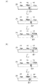
図1(a)、(b)に本発明を適用可能な撮像制御装置の一実施形態としてのデジタルカメラ100の外観図を示す。図1(a)はデジタルカメラ100の前面斜視図であり、図1(b)はデジタルカメラ100の背面斜視図である。図1において、表示部28は画像や各種情報を表示する表示部である。レンズユニット150はレンズを含むレンズユニットである。シャッターボタン61は撮影指示を行うための操作部である。モード切替スイッチ60は各種モードを切り替えるための操作部である。電源スイッチ72はデジタルカメラ100の電源のON及びOFFを切り替える操作部材である。十字キー74は上、下、左、右部分をそれぞれ押し込み可能な4方向キーである。十字キー74の押された部分に応じた操作が可能である。SETボタン75は、主に選択項目の決定などに用いられる押しボタンである。再生ボタン79は、撮影モードと再生モードとを切り替える操作ボタンである。撮影モード中に再生ボタン79を押下することで再生モードに移行し、記録媒体200に記録された画像のうち最新の画像を表示部28に表示させることができる。MENUボタン73は操作部70に含まれ、ユーザがデジタルカメラ100の各種設定を行う際に設定項目及び設定内容を表示部28に表示するためのボタンである。メニュー画面においては、時刻設定や表示の設定、通信に関する設定や、連続撮影速度(連写速度、連続撮影を行う間隔)の設定を行うことができる。
FIGS. 1A and 1B show external views of a
タッチバー29は、シャッターボタン61とは別に設けられる操作部材であり、シャッターボタン61を押した状態でも操作可能な位置に設置される。ユーザは、カメラを保持するためのグリップ部90を中指、薬指、小指と手のひらとで握り、人差し指をシャッターボタン61にのせ、親指をタッチバー29に置くことができる。
The
シャッターボタン61、電源スイッチ72、十字キー74、SETボタン75、再生ボタン79、タッチバー29、MENUボタン73は、操作部70に含まれる。
The
ファインダー16はファインダー内表示部(不図示)を観察することで、レンズユニット150を通して得た被写体像の焦点や構図の確認を行うための覗き込み型のファインダーである。
The
図2は、本実施形態によるデジタルカメラ100の構成例を示すブロック図である。レンズユニット150は、交換可能な撮影レンズを搭載するレンズユニットである。レンズ103は通常、複数枚のレンズから構成されるが、ここでは簡略して一枚のレンズのみで示している。通信端子6はレンズユニット150がデジタルカメラ100側と通信を行う為の通信端子であり、通信端子10はデジタルカメラ100がレンズユニット150側と通信を行う為の通信端子である。レンズユニット150は、この通信端子6,10を介してシステム制御部50と通信し、内部のレンズシステム制御回路4によって絞り駆動回路2を介して絞り102の制御を行い、AF駆動回路3を介して、レンズ103の位置を変位させることで焦点を合わせる。
FIG. 2 is a block diagram showing a configuration example of the
シャッター101は、システム制御部50の制御で撮像部22の露光時間を自由に制御できるフォーカルプレーンシャッターである。
The
撮像部22は光学像を電気信号に変換するCCDやCMOS素子等で構成される撮像素子である。A/D変換器23は、アナログ信号をデジタル信号に変換する。A/D変換器23は、撮像部22から出力されるアナログ信号をデジタル信号に変換するために用いられる。
The
画像処理部24は、A/D変換器23からのデータ、又は、メモリ制御部15からのデータに対し所定の画素補間、縮小といったリサイズ処理や色変換処理を行う。また、画像処理部24では、撮像した画像データを用いて所定の演算処理が行われ、得られた演算結果に基づいてシステム制御部50が露光制御、測距制御を行う。これにより、TTL(スルー・ザ・レンズ)方式のAF(オートフォーカス)処理、AE(自動露出)処理、EF(フラッシュプリ発光)処理が行われる。画像処理部24では更に、撮像した画像データを用いて所定の演算処理を行い、得られた演算結果に基づいてTTL方式のAWB(オートホワイトバランス)処理も行っている。
The image processing unit 24 performs predetermined pixel interpolation, resizing processing such as reduction, and color conversion processing on data from the A /
A/D変換器23からの出力データは、画像処理部24及びメモリ制御部15を介して、或いは、画像処理部24を介さずメモリ制御部15を介してメモリ32に直接書き込まれる。メモリ32は、撮像部22によって得られA/D変換器23によりデジタルデータに変換された画像データや、表示部28に表示するための画像データを格納する。
Output data from the A /
メモリ32は、所定枚数の静止画像や所定時間の動画像および音声を格納するのに十分な記憶容量を備えている。また、メモリ32は画像表示用のメモリ(ビデオメモリ)を兼ねている。D/A変換器19は、メモリ32に格納されている画像表示用のデータをアナログ信号に変換して表示部28に供給する。こうして、メモリ32に書き込まれた表示用の画像データはD/A変換器19を介して表示部28により表示される。
The
表示部28は、LCD等の表示器上に、D/A変換器19からのアナログ信号に応じた表示を行う。A/D変換器23によって一度A/D変換されメモリ32に蓄積されたデジタル信号をD/A変換器19においてアナログ変換し、表示部28やファインダー16内の表示部に逐次転送して表示する。そして、逐次転送して表示することで、表示部28は電子ビューファインダとして機能し、スルー画像表示(ライブビュー表示)を行える。
The
不揮発性メモリ56は、システム制御部50によって電気的に消去・記録・読出し可能な記録媒体としてのメモリであり、例えばEEPROM等が用いられる。不揮発性メモリ56には、システム制御部50の動作用の定数、プログラム等が記憶される。ここでいう、プログラムとは、本実施形態にて後述する各種フローチャートを実行するためのコンピュータプログラムのことである。
The
システム制御部50は、少なくとも1つのプロセッサーを内蔵し、デジタルカメラ100全体を制御する。前述した不揮発性メモリ56に記録されたプログラムを実行することで、後述する本実施形態の各処理を実現する。システムメモリ52には、RAMが用いられる。システムメモリ52には、システム制御部50の動作用の定数、変数、不揮発性メモリ56から読み出したプログラム等を展開する。また、システム制御部50はメモリ32、D/A変換器19、表示部28等を制御することにより表示制御も行う。
The system control unit 50 incorporates at least one processor and controls the entire
モード切替スイッチ60、シャッターボタン61、操作部70はシステム制御部50に各種の動作指示を入力するための操作手段である。モード切替スイッチ60は、システム制御部50の動作モードを静止画記録モード、動画撮影モード、再生モード等のいずれかに切り替える。静止画記録モードに含まれるモードとして、連続撮影モード、オート撮影モード、オートシーン判別モード、マニュアルモード、撮影シーン別の撮影設定となる各種シーンモード、プログラムAEモード、カスタムモード等がある。モード切替スイッチ60で、メニュー画面に含まれるこれらのモードのいずれかに直接切り替えられる。あるいは、モード切替スイッチ60でメニュー画面に一旦切り換えた後に、メニュー画面に含まれるこれらのモードのいずれかに、他の操作部材を用いて切り替えるようにしてもよい。同様に、動画撮影モードにも複数のモードが含まれていてもよい。
A
第1シャッタースイッチ62は、デジタルカメラ100に設けられたシャッターボタン61の操作途中、いわゆる半押し(撮影準備指示)でONとなり第1シャッタースイッチ信号SW1を発生する。第1シャッタースイッチ信号SW1により、AF(オートフォーカス)処理、AE(自動露出)処理、AWB(オートホワイトバランス)処理、EF(フラッシュプリ発光)処理等の動作を開始する。第2シャッタースイッチ64は、シャッターボタン61の操作完了、いわゆる全押し(撮影指示)でONとなり、第2シャッタースイッチ信号SW2を発生する。システム制御部50は、第2シャッタースイッチ信号SW2により、撮像部22による静止画撮像動作、撮像部22からの信号読み出しから記録媒体200に画像データを書き込むまでの一連の撮影処理の動作を開始する。
During the operation of the
操作部70の各操作部材は、表示部28に表示される種々の機能アイコンを選択操作することなどにより、場面ごとに適宜機能が割り当てられ、各種機能ボタンとして作用する。操作部70には、機能ボタンと、タッチパネル27とタッチバー29が含まれており、タッチ検出面へのタッチ操作を受け付ける。タッチ操作については後述する。機能ボタンとしては、例えば終了ボタン、戻るボタン、画像送りボタン、ジャンプボタン、絞込みボタン、属性変更ボタン等がある。例えば、メニューボタンが押されると各種の設定可能なメニュー画面が表示部28に表示される。利用者は、表示部28に表示されたメニュー画面と、上下左右の4方向ボタンやSETボタンとを用いて直感的に各種設定を行うことができる。
Each operation member of the
電源制御部80は、電池検出回路、DC−DCコンバータ、通電するブロックを切り替えるスイッチ回路等により構成され、電池の装着の有無、電池の種類、電池残量の検出を行う。また、電源制御部80は、その検出結果及びシステム制御部50の指示に基づいてDC−DCコンバータを制御し、必要な電圧を必要な期間、記録媒体200を含む各部へ供給する。
The power
電源部30は、アルカリ電池やリチウム電池等の一次電池やNiCd電池やNiMH電池、Li電池等の二次電池、ACアダプター等からなる。 The power supply unit 30 includes a primary battery such as an alkaline battery or a lithium battery, a secondary battery such as a NiCd battery, a NiMH battery, or a Li battery, an AC adapter, or the like.
記録媒体I/F18は、メモリカードやハードディスク等の記録媒体200とのインターフェースである。記録媒体200は、撮影時に画像を記録するためのメモリカード等の不揮発性の記録媒体であり、半導体メモリや光ディスク、磁気ディスク等から構成される。
The recording medium I /
操作部70に含まれるタッチバー29、タッチパネル27について説明する。タッチパネル27は、表示部28に対する接触を検知可能なタッチパネルである。タッチパネル27と表示部28とは一体的に構成することができる。例えば、タッチパネル27を光の透過率が表示部28の表示を妨げないように構成し、表示部28の表示面の上層に取り付ける。そして、タッチパネルにおける入力座標と、表示部28上の表示座標とを対応付ける。これにより、恰もユーザが表示部28上に表示された画面を直接的に操作可能であるかのようなGUI(グラフィカルユーザーインターフェース)を構成することができる。システム制御部50はタッチパネル27、タッチバー29への以下の操作、あるいは状態を検出できる。なお、タッチバーは図1、2の例では表示面と一体となっていないが、表示面と一体となっていてもよい。
・タッチ面にタッチしていなかった指やペンが新たにタッチ面にタッチしたこと。すなわち、タッチの開始(以下、タッチダウン(Touch−Down)と称する)。
・タッチ面を指やペンでタッチしている状態であること(以下、タッチオン(Touch−On)と称する)。
・タッチ面を指やペンでタッチしたまま移動していること(以下、タッチムーブ(Touch−Move)と称する)。
・タッチ面へタッチしていた指やペンを離したこと。すなわち、タッチの終了(以下、タッチアップ(Touch−Up)と称する)。
・タッチ面に何もタッチしていない状態(以下、タッチオフ(Touch−Off)と称する)。
The
-A finger or pen that did not touch the touch surface has newly touched the touch surface. That is, the start of touch (hereinafter referred to as touch-down).
-A state in which the touch surface is touched with a finger or a pen (hereinafter referred to as "Touch-On").
-Moving while touching the touch surface with a finger or a pen (hereinafter referred to as "Touch-Move").
-Release the finger or pen that was touching the touch surface. That is, the end of the touch (hereinafter referred to as touch-up).
A state in which nothing is touched on the touch surface (hereinafter, referred to as touch-off).
タッチダウンが検出されると、同時にタッチオンであることも検出される。タッチダウンの後、タッチアップが検出されない限りは、通常はタッチオンが検出され続ける。タッチムーブが検出されるのもタッチオンが検出されている状態である。タッチオンが検出されていても、タッチ位置が移動していなければタッチムーブは検出されない。タッチしていた全ての指やペンがタッチアップしたことが検出された後は、タッチオフとなる。 When touch down is detected, touch on is also detected at the same time. After touch down, touch on normally continues to be detected unless touch up is detected. The touch move is also detected in the state where the touch on is detected. Even if the touch on is detected, if the touch position is not moved, the touch move is not detected. After it is detected that all the fingers and pens that have been touched touch up, the touch is off.
これらの操作・状態や、タッチ面上に指やペンがタッチしている位置座標は内部バスを通じてシステム制御部50に通知され、システム制御部50は通知された情報に基づいてタッチ面上にどのような操作が行なわれたかを判定する。タッチムーブについてはタッチパネル上で移動する指やペンの移動方向についても、位置座標の変化に基づいて、タッチパネル27上の垂直成分・水平成分毎、タッチバー29の水平成分に対して判定できる。またタッチ面上をタッチダウンから一定のタッチムーブを経てタッチアップをしたとき、ストロークを描いたこととする。素早くストロークを描く操作をフリックと呼ぶ。フリックは、タッチ面上に指をタッチしたままある程度の距離だけ素早く動かして、そのまま離すといった操作であり、言い換えればタッチ面上を指ではじくように素早くなぞる操作である。所定距離以上を、所定速度以上でタッチムーブしたことが検出され、そのままタッチアップが検出されるとフリックが行なわれたと判定できる。また、所定距離以上を、所定速度未満でタッチムーブしたことが検出された場合はドラッグが行なわれたと判定するものとする。タッチパネル、タッチバーは、抵抗膜方式や静電容量方式、表面弾性波方式、赤外線方式、電磁誘導方式、画像認識方式、光センサ方式等、様々な方式のタッチパネルのうちいずれの方式のものを用いても良い。方式によって、タッチパネル、タッチバーに対する接触があったことでタッチがあったと検出する方式や、タッチパネル、タッチバーに対する指やペンの接近があったことでタッチがあったと検出する方式ものがあるが、いずれの方式でもよい。
The system control unit 50 is notified of these operations / states and position coordinates where a finger or pen is touching on the touch surface through the internal bus, and the system control unit 50 determines which on the touch surface is based on the notified information. It is determined whether such an operation has been performed. With regard to the touch move, the movement direction of the finger or pen moving on the touch panel can also be determined for each vertical component and horizontal component on the
次に、図3を用いて本実施形態の撮影処理について説明する。この処理は、不揮発性メモリ56に記録されたプログラムをシステムメモリ52に展開してシステム制御部50が実行することで実現する。なお、この処理は、デジタルカメラ100に電源が入り撮影モードになると開始する。
Next, the photographing process of the present embodiment will be described with reference to FIG. This processing is realized by expanding the program recorded in the
S100では、システム制御部50は、現在の撮影モードが連続撮影モードであるか否かを判定する。連続撮影モードであると判定した場合はS101へ進み、そうでない場合は、S117へ進む。 In S100, the system control unit 50 determines whether the current shooting mode is the continuous shooting mode. If it is determined that the continuous shooting mode is selected, the process proceeds to step S101. If not, the process proceeds to step S117.
S101では、システム制御部50は、撮影に関するメニュー画面において連続撮影速度Sを変更されたか否かを判定する。撮影に関するメニュー画面は、MENUボタン73の押下によって表示することができる。連続撮影速度Sは、30fps、20fps、10fpsなどから選択できる。連続撮影速度Sを変更する操作がされたと判定した場合は、S102へ進み、そうでない場合は、S103へ進む。
In S101, the system control unit 50 determines whether or not the continuous imaging speed S has been changed on the menu screen regarding imaging. The menu screen related to shooting can be displayed by pressing the
S102では、システム制御部50は、メニュー画面において設定された連続撮影速度S=αとして設定し、システムメモリ52に記録する。設定された連続撮影速度Sに応じて連続撮影におけるフレーム間のインターバル時間Tが算出される。連続撮影速度Sの値が小さいほどインターバルTは短く、連続撮影速度Sの値が大きいほどインターバルTは長くなる。なお、ユーザがメニュー画面において連続撮影速度を変更していない場合には、初期設定としてS=αは10fpsが設定される。
In S102, the system control unit 50 sets the continuous shooting speed S = α set on the menu screen, and records it in the
S103では、システム制御部50は、撮影指示がされたか否かを判定する。撮影指示は、シャッターボタン61の押下によって行うことができる。撮影指示がされたと判定した場合は、S104へ進み、そうでない場合は、S116へ進む。
In step S103, the system control unit 50 determines whether a shooting instruction has been issued. A shooting instruction can be issued by pressing the
S104では、システム制御部50は、連続撮影における撮影枚数N=1枚目の撮影が行われる。1枚(=1フレーム)の撮影は図5のような流れとなっている。まずAEセンサによって測光を行い、撮像部22にて露光を行い、各画素の出力信号は順次読み出され、A/D変換機23でデジタル信号へと変換される。また、デジタル変換された各画素の出力データに対して画像処理部24にて画像処理が行われ、生成された画像データはメモリ32に格納する。ここまでの処理を1枚の撮影であり、その後メモリ32に格納された画像データは記録媒体200へと格納される。
In S104, the system control unit 50 performs photographing of the number N = 1 of images in the continuous photographing. The shooting of one image (= 1 frame) is as shown in FIG. First, photometry is performed by the AE sensor, exposure is performed by the
S105では、システム制御部50は、1枚の撮影処理完了に伴い、次の撮影を開始するまでのインターバル時間Tのカウントを開始する。 In step S105, the system control unit 50 starts counting the interval time T until the start of the next shooting in accordance with the completion of the shooting processing of one sheet.
S106では、システム制御部50は、撮影指示が解除されたか否かを判定する。シャッターボタン61の押下がされなくなったことを検出した場合、S101へ戻る。また、シャッターボタン61が押下されている場合には、ユーザが撮影を継続していると判定し、S107へ進む。
In S106, the system control unit 50 determines whether the imaging instruction has been released. If it is detected that the
S107では、システム制御部50は、タッチバー29へのタッチがされたか否かの判定を行う。ユーザが指等でタッチバー29にタッチを行った場合、タッチを検出する。タッチバー29へのタッチがされたと判定された場合はS108へ進み、そうでない場合は、S114へ進む。
In step S107, the system control unit 50 determines whether the
S108では、システム制御部50は、システムメモリ52に格納されているタッチフラグをONにし、タッチバー29がタッチされている状態であることを記録する。タッチフラグは連続撮影が開始されてからタッチバー29へのタッチがされたか否かを示すフラグである。
In S108, the system control unit 50 turns on the touch flag stored in the
S109では、システム制御部50は、ユーザがタッチバー29のどの領域にタッチしているのかを判定する。図4(a)には、タッチバー29の領域と連続撮影速度Sの関係についての一例を示す。図4(a)においては、タッチバー29を3つの領域に分割し、各領域に連続撮影速度Sを割り当てている。S109においては、この3つの領域のうちどの領域にタッチがされているかを判定する。なお、領域の数は3つに限らない。連続撮影速度Sは、タッチバー29の座標0〜X1、X1〜X2、X2〜X3の範囲の3つの領域をそれぞれA1、A2、A3とし、各領域に割り当てる連続撮影速度Sをそれぞれβ1、β2、β3としている。
In S109, the system control unit 50 determines which area of the
S110では、システム制御部50は、S109で取得したタッチ領域に応じて連続撮影速度S=βを設定する。このβの値は、S101で設定された連続撮影速度S=α以下の値である。図4(a)に示す領域のうち、最も右の領域A3における連続撮影速度S=β3を、メニュー画面において設定したαとしている。メニュー画面にて、連続撮影速度S=10fpsと設定された場合、例えばβ3=10fpsとなり、β2=6fps、β1=3fpsというように割り当てる。このように、タッチバー29の各領域に対して、連続撮影速度Sは、最も右の領域をメニュー画面で設定した値とし、左の領域ほど低速になるようにする。図4(a)に示した、それぞれの連続撮影速度S=β1、β2、β3(=α)での連続撮影イメージを図4(b)に示す。連続撮影速度Sが変更された時には、各撮影間のインターバル時間を変更する。連続撮影速度S=β1、β2、β3の時のインターバル時間をそれぞれT1、T2、T3とすると、T1>T2>T3の関係であり、連続撮影速度Sが速くなるほどインターバル時間を短くなる。よって、タッチした領域A1であれば連続撮影速度を遅くすることができるので、被写体にあまり動きがない場合や、被写体が小さく沢山撮影しても画像に変化がない場合など、大量に撮影をし過ぎてしまい記録媒体200に余計に画像データが入らない。一方で、被写体の動きが早かったり、被写体が近くにいて大量に撮影をしておきたいときなどには、A3をタッチすればシャッターチャンスを逃しにくくなる。このように、タッチする領域に応じて連続撮影理速度Sを変更することができるので、ユーザが連続撮影中に被写体の様子に応じて柔軟に操作性良く連続撮影を行うことができる。また、連続撮影速度Sの設定を行う操作部材として、力をかけて押下しなくても検出可能なタッチバー29を用いることで、操作時の振動をボタン操作よりも少なくすることができるため、操作時の手振れの発生が少なくなる。タッチバー29はデジタルカメラ100の上面ではなく背面に配置されており、タッチをしたときにレンズの光軸がぶれにくい。
In S110, the system control unit 50 sets the continuous imaging speed S = β in accordance with the touch area acquired in S109. The value of β is a value equal to or less than the continuous shooting speed S = α set in S101. Of the areas shown in FIG. 4A, the continuous shooting speed S = β3 in the rightmost area A3 is α set on the menu screen. When the continuous shooting speed S = 10 fps is set on the menu screen, for example, β3 = 10 fps, and β2 = 6 fps and β1 = 3 fps are allocated. As described above, for each area of the
S111では、システム制御部50は、インターバルTがS110で設定された連続撮影速度S=βの値に応じて決められる時間Tβだけ経過したか否かを判定する。Tβだけ経過していればS112へ進み、経過していなければS106に戻り、撮影指示解除の判定を行う。 In S111, the system control unit 50 determines whether or not a time Tβ determined in accordance with the value of the continuous shooting speed S = β set in S110 has elapsed for the interval T. If T.beta. Has elapsed, the process proceeds to S112, and if not, the process returns to S106, and it is determined that the photographing instruction has been canceled.
S112では、システム制御部50は、インターバルTが所定の時間経過したため、カウントをリセットする。 In S112, the system control unit 50 resets the count because the interval T has passed a predetermined time.
S113では、撮影枚数N+1枚目の撮影が行われる。撮影の内容はS104と同様、図5に示す通りである。撮影が完了したらS105に戻り、インターバルTのカウントを再度開始する。 In S113, the photographing of the number N + 1 of the photographed number is performed. The contents of photographing are as shown in FIG. 5 as in S104. When the photographing is completed, the process returns to S105, and the counting of the interval T is started again.
S114では、システム制御部50は、システムメモリ52におけるタッチフラグのON、OFFを判定する。タッチフラグがONである場合はS111のインターバルTの経過判定に進み、タッチフラグがOFFである場合はS115に進む。S107でタッチが発生していないと判定され、S114でタッチフラグありと判定されたことから、現在の連続撮影中にタッチバー29に対するタッチ操作が行われ、その後タッチバー29からタッチが離されたということがわかる。つまり、連続撮影速度Sは、メニュー画面において設定されたS=αから、タッチバー29へのタッチ操作によってβへ変更されたということになる。このような場合、タッチバー29からタッチを離す直前までのタッチ位置に応じて設定されていた連続撮影速度Sが、タッチバー29からタッチを離した後でも維持される。
In S114, the system control unit 50 determines whether the touch flag in the
S115では、システム制御部50は、インターバルTがメニュー画面で設定された連続撮影速度S=αの値に応じた時間Tαだけ経過したか否かを判定する。Tα経過していればS112へ進み、経過していなければS106に戻り、撮影指示解除の判定を行う。S107でタッチが発生していないと判定され、S114でタッチフラグがないと判定されたことから、連続撮影開始後、一度もタッチバー29の操作による連続撮影速度Sの変更が行われていないことがわかる。そのため、連続撮影速度Sはユーザがメニュー画面で設定した速度(もしくは初期設定の速度)で撮影が行われる。このように、ユーザが特にタッチバー29へのタッチ操作をしていない場合には、メニュー画面において設定されている速度S=αから撮影速度を遅くせずに撮影を行うので、ユーザの意図せず撮り逃してしまうことがないようにしている。
In S115, the system control unit 50 determines whether or not the interval T has elapsed by a time Tα according to the value of the continuous shooting speed S = α set on the menu screen. If Tα has elapsed, the process proceeds to S112. If Tα has not elapsed, the process returns to S106, and it is determined that the shooting instruction has been canceled. Since it is determined in S107 that no touch has occurred and it is determined in S114 that there is no touch flag, it is not possible to change the continuous shooting speed S by the operation of the
S116では、システム制御部50は、撮影モードを終了する操作がされたか否かを判定する。撮影モードから、再生モードへの移行、電源のOFFなどがされると撮影モードが終了する。撮影モードを終了する操作がされたと判定した場合は、撮影処理を終了し、そうでない場合には、S101へ戻る。 In S116, the system control unit 50 determines whether an operation to end the shooting mode has been performed. When the shooting mode is switched to the playback mode, the power is turned off, etc., the shooting mode ends. If it is determined that the operation to end the shooting mode has been performed, the shooting process is ended, and if not, the process returns to S101.
S117〜S119は、連続撮影モード以外のモードでの処理を示している。連続撮影モード以外の処理には、シャッターボタン61の押下時間に関わらず1枚撮影する単写撮影をする通常のモード、動画撮影モードなどがある。
Steps S117 to S119 indicate processing in modes other than the continuous shooting mode. The processes other than the continuous shooting mode include a normal mode in which a single shot for shooting one image regardless of the pressing time of the
S117では、システム制御部50は、S103と同様に、撮影指示がされたか否かを判定する。撮影指示がされたと判定した場合は、S118へ進み、そうでない場合は、S119へ進む。 In S117, the system control unit 50 determines, as in S103, whether a photographing instruction has been issued. If it is determined that the imaging instruction has been issued, the process proceeds to step S118. If not, the process proceeds to step S119.
S118では、システム制御部50は、撮影を1回(1枚)行う(単写)。撮影の方法についてはS104で説明した方法と同様である。1回撮影をした後は、シャッターボタン61が押下された状態から解除され、再び押下されると撮影が行われる。なお、動画モードの場合には撮影開始指示に応じて動画の記録が開始され、撮影終了指示に応じて動画の記録が停止される。
In S118, the system control unit 50 performs one shooting (single shooting) (single shooting). The photographing method is the same as the method described in S104. After shooting once, the
S119では、システム制御部50は、S116と同様に撮影モードを終了する操作がされたか否かを判定する。撮影モードを終了する操作がされたと判定した場合は、撮影処理を終了し、そうでない場合には、S117へ戻る。 In step S119, the system control unit 50 determines whether an operation to end the shooting mode has been performed as in step S116. If it is determined that the operation to end the shooting mode has been performed, the shooting process is ended, and if not, the process returns to step S117.
次に、図3に示した撮影処理について図5(b)、(c)を用いて説明する。 Next, the photographing process shown in FIG. 3 will be described using FIGS. 5 (b) and 5 (c).
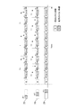
図5(b)は、図4に示したタッチバー29の領域の分割で、連続撮影中にユーザがタッチバー29にタッチしていない状態から、領域A1へタッチし、その後に領域A2→A3へとタッチ位置を移動することを示している。このようにタッチ位置を移動することにより、連続撮影速度Sを上げる場合の連続撮影タイミングチャートの一例である。図5(b)において、連続撮影開始から(N+1)枚目の撮影まではタッチバー29をタッチしていない状態である。連続撮影開始後、タッチバー29へのタッチがない状態では、連続撮影速度S=α(メニュー画面での設定もしくは初期値)で行われる。S=αは、タッチバー29の領域A3に割り付けた10fpsであるため、インターバルTは連続撮影速度10fpsに応じた値であるT3で連続撮影が行われる。(N+1)枚目の撮影中の時刻t1にて、ユーザがタッチバー29の領域A1にタッチし、連続撮影速度Sを10fpsから3fpsに変更する操作を行ったとする。この場合、(N+1)枚目の撮影後、3fpsに応じたインターバルT1だけ時間が経過した後、(N+2)枚目の撮影が行われる。次に、(N+2)枚目の撮影後にインターバルT1が経過する前の時刻t2にユーザがタッチバー29上の指を領域A2に移動させて、連続撮影速度Sを3fpsから6fpsに変更する操作を行ったとする。時刻t2は、(N+2)枚目の撮影後、連続撮影速度S=6fpsに応じたインターバルT2が経過する前であるため、(N+2)枚目の撮影後からインターバルT2が経過後した後に(N+3)枚目の撮影が行われる。(N+3)枚目から(N+4)枚目の撮影は、タッチ領域の変更は行われず、連続撮影速度S=6fpsのまま、インターバルT2で撮影が行われる。(N+4)枚目の撮影後、インターバルT2が経過する前の時刻t3にユーザがタッチバー29上の指を領域A3に移動させて、連続撮影速度Sを6fpsから10fpsに変更する操作を行ったとする。この時、インターバルは10fpsに応じたT3に変更することになるが、時刻t3は(N+4)枚目の撮影後にT3以上の時間が経過した後の時刻である。この場合、(N+5)枚目の撮影は、時刻t3にタッチ領域の変更が行われたと判定された時点ですぐに行われる。このように、連続撮影速度を早くする方へと変更する操作が行われた場合には、変更前のインターバル時間の計時中であり、インターバル時間が経過しなくても、変更操作が行われた時点で次の撮影を行う。変更操作が行われた時点でユーザは変更前の連続撮影速度よりも早くしたいと考えているので、少しでも早く次の撮影を行うことでユーザの意図した撮影が行うことができる。
FIG. 5B shows the division of the area of the
図5(c)は、タッチバー29の領域A3がタッチされている状態からユーザが領域A2→領域A1指を移動し、連続撮影速度Sを下げる操作をした場合の連続撮影タイミングチャートの一例である。M枚目までの連続撮影は、タッチ領域A3に割り付けた連続撮影速度S=10fpsに応じたインターバルT3で行われる。M枚目の撮影後、T3経過前にユーザがタッチバー29上のタッチ領域をA2に移動させたとする。この時、連続撮影速度Sは領域A2に割り付けた6fpsとなり、(M+1)枚目の撮影はM枚目の撮影後のインターバルがT2だけ経過した後に行われる。更に(M+2)枚目の撮影中である時刻t5にユーザが指をA1に移動したとする。この時、連続撮影速度Sは領域A1に割り付けた3fpsとなり、(M+2)枚目の撮影後、インターバルT1経過後に(M+3)枚目の撮影が行われる。(M+3)枚目の撮影後のインターバル時間である時刻t6に、ユーザがタッチバー29からタッチを離したとする。このようにタッチバー29からタッチを離した場合は、タッチを離す直前の連続撮影速度Sを維持する。そのため、(M+3)枚目以降は、再度タッチバー29へのタッチがされるまで、連続撮影速度S=3fpsで連続撮影が継続される。ユーザは、連続撮影速度を変更したいときにだけ、タッチをすればその後タッチを離しても所望の連続撮影速度での撮影を継続することができる。
FIG. 5C is an example of a continuous imaging timing chart in the case where the user moves the area A2 → area A1 finger from the state where the area A3 of the
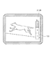
次に、図6を用いて、連続撮影速度を変更する場合のユースケースについて説明する。図6は、電車が近づいてくる際の撮影を一例として示している。メインの被写体である電車が正面に来たタイミングの画像を撮影したい場合、電車が正面に来る前からシャッターボタン61を押して連続撮影を開始するが、まだ電車が遠くにある時刻t1では被写体が小さいので高速で連続撮影をしなくてもよい。よって、タッチバー29の領域A1をタッチし、3fpsで連続撮影を行う。その後、電車が近づいてきた時刻t2でタッチバー29の領域A1にある指を領域A2に移動させて6fpsに連続撮影速度を上げる。そして、電車が正面付近の、最も多くの画像を撮影したい時刻t3で指を領域A3まで移動させ、10fpsに連続撮影速度を上げる。電車が正面を通り過ぎた時刻t4では、指を領域A2に戻し、6fpsに下げる。このように、ユーザが連続撮影速度を変更することができるので、被写体が遠く、被写体の変化が少ないような場合には、連続撮影速度を遅くし、余分な撮影をせずに済む。また、連続撮影は、電車の通過を撮影する場合のように、同じ被写体を継続して撮影することが多いが、撮影の途中でメニュー画面を開いて速度を変更する操作をしてしまうと、その期間の撮影が行えなくなってしまう。しかしながら、連続撮影中にタッチ領域を変えるだけでよいので、連続撮影を中断せずに同じ被写体を継続して撮影することができる。
Next, a use case for changing the continuous shooting speed will be described with reference to FIG. FIG. 6 shows an example of shooting when the train approaches. If you want to shoot an image when the main subject, the train, comes to the front, press the
次に、図7(a)、(b)を用いてタッチ領域をまたぐときの連続撮影速度の決め方について説明する。タッチバー29上で指を移動させる際、タッチバー29で検出されたタッチ位置が2つの領域の間となった場合は、直前の連続撮影速度Sを維持する。図7(a)は、指を左から右(A2からA3)に移動させて、連続撮影速度Sを上げる操作を示し、図7(b)は、指を右から左(A3からA2)に移動させて、連続撮影速度Sを下げる操作を示す。図7(a)において、タッチ点301が領域A2とA3の間にあるときは、直前にタッチ点301のあった領域A2の連続撮影速度S=6fpsを維持し、タッチ点が完全に領域A3に入った段階で10fpsに変更される。図7(b)においては、タッチ点301が領域A2とA3の間にあるとき、直前にタッチ点301のあった領域A3の連続撮影速度S=10fpsを維持し、タッチ点が完全に領域A2に入った段階で6fpsに変更される。
Next, how to determine the continuous shooting speed when straddling the touch area will be described with reference to FIGS. 7A and 7B. When moving the finger on the
2つのタッチ領域を共にタッチしている場合には、直前の連続撮影速度Sを継続するようにするので意図せず連続撮影の速度が変わらない。例えば、ユーザがA2の領域のうち、A3よりの位置をタッチしている状態において、タッチしている指を立てた状態から寝かせた状態にするなどしてタッチ範囲が途中で変わり隣の領域にもタッチしたとしても連続撮影速度が変わらない。ユーザがA2をタッチしているつもりである可能性が高いので、A3の領域にタッチをしていたとしても連続速度を変えないことでユーザはより意図に沿った撮影を行うことができる。 When two touch areas are touched together, the continuous shooting speed S immediately before is continued, so the speed of continuous shooting does not change unintentionally. For example, in a state in which the user touches the position of A3 in the area A2, the touch range changes in the middle and the next area is changed, for example, by setting the touch finger up and turning it to a lying state. Even if you touch it, the continuous shooting speed does not change. Since there is a high possibility that the user intends to touch A2, the user can perform photographing more in line with the intention by not changing the continuous speed even if the user is touching the area A3.
なお、本実施形態では連続撮影中に連続撮影速度Sを変更する部材としてタッチバー29を用いているが、タッチ操作部材であればタッチバー29に限定されるものではなく、タッチパネル27でも代用可能である。連続撮影速度Sの変更をタッチパネル27で行う場合の一例を図8に示す。図8のように、タッチパネル27と一体になっている表示部28上の、ユーザがシャッターボタン61を押しながら別の指で操作可能な部分に複数の連続撮影速度Sを割り当てたバー700を表示する。タッチバー29での操作と同様、連続撮影中に表示したバー700のどの領域をタッチしているかに応じて、連続撮影速度Sを変更するようにしてもよい。
In the present embodiment, the
以上、説明した実施形態によれば、ユーザが連続撮影中に操作性良く連続撮影の間隔を変更することができる。連続撮影のうち、タッチバー29をタッチしていない撮影期間においては設定されている連続撮影のうち最高速度で撮影をし、タッチバー29へのタッチがされている撮影期間においてはタッチバー29のタッチ位置に応じて連続撮影の撮影を行う間隔を決める。これにより、ユーザはタッチバー29をタッチしていない場合には、ユーザの意図せずに画像が記録されないことがないようにし、タッチバー29をタッチすれば余計に撮影を行わないようにする。ユーザが被写体の様子に応じて連続撮影の間隔を操作性良く決め、連続撮影中に柔軟に撮影を行うことができる。
As described above, according to the embodiment described above, the user can change the interval of continuous shooting with good operability during continuous shooting. During continuous shooting, shooting is performed at the highest speed in the continuous shooting that is set during the shooting period in which the
[変形例]
上述の実施形態においては、連続撮影速度Sを変更した場合、設定された連続撮影速度Sに応じてインターバルTを変更し、撮影を行う時間間隔を変更することを説明した。
[Modification]
In the above embodiment, when the continuous shooting speed S is changed, it has been described that the interval T is changed according to the set continuous shooting speed S, and the time interval for shooting is changed.
しかし、撮影間隔は変更せず、連続撮影速度Sに応じたインターバルが経過した時刻の画像にフラグを付加し、撮影終了後に記録媒体200に記録された画像のうちフラグのついた画像のみを残し、残りを削除してもよい。もしくはメモリ32から記録媒体200へフラグのついた画像のみを格納し、フラグのついていない画像を削除してもよい。また、記録媒体200からフラグが付いている画像のみを外部メディアに保存しても良い。図9が、連続撮影速度とフラグの関係について説明するための図である。変形例においては、撮影はメニュー画面において設定された(もしくは初期設定である)S=α(インターバルはT3)でシャッターボタン61を押下している間撮影が行われる。このインターバルは、どの連続撮影速度Sの設定においても変更されない。タッチバー29で連続撮影速度Sが変更された場合には、その値に応じた間隔で画像にフラグを付けていく。撮影時に、領域A1がタッチされている場合にはT1、領域A2がタッチされている場合にはT2の時間が撮影後に経過した後、最初に撮影された画像にフラグを付加して、記録媒体200記録する。図9に示す例では、領域A1がタッチされている場合は、N枚目の画像からT1経過後の(N+3)枚目、さらにT1経過後の(N+6)枚目、さらにT1経過後の(N+9)枚目の画像にフラグを付加して記録する。領域A2がタッチされている場合は、N枚目の画像からT2経過した後の最初の画像である(N+2)枚目の画像にフラグが付加され、その後同様にして(N+4)枚目、(N+6)枚目、(N+8)枚目の画像にフラグが付加され、記録される。このように、連続撮影速度Sが変更された際、実際の撮影速度は変更せずに、連続撮影速度Sに応じた間隔で間引いて画像を記録(一部を記録)することで、記録する撮影画像の間隔を変化させるようにしても良い。
However, the shooting interval is not changed, a flag is added to the image at the time when the interval according to the continuous shooting speed S has elapsed, and only the flagged image is left among the images recorded on the
なお、タッチバー29へのタッチに応じて連続撮影速度を遅くすることを説明したが早くするようにしてもよい。
Although it has been described that the continuous shooting speed is reduced according to the touch on the
なお、システム制御部50が行うものとして説明した上述の各種の制御は1つのハードウェアが行ってもよいし、複数のハードウェアが処理を分担することで、装置全体の制御を行ってもよい。 The above-described various controls described as being performed by the system control unit 50 may be performed by one hardware, or a plurality of hardware may control the entire apparatus by sharing processing. .
また、本発明をその好適な実施形態に基づいて詳述してきたが、本発明はこれら特定の実施形態に限られるものではなく、この発明の要旨を逸脱しない範囲の様々な形態も本発明に含まれる。さらに、上述した各実施形態は本発明の一実施形態を示すものにすぎず、各実施形態を適宜組み合わせることも可能である。 Further, although the present invention has been described in detail based on its preferred embodiments, the present invention is not limited to these specific embodiments, and various forms within the scope of the present invention are also included in the present invention. included. Furthermore, each embodiment mentioned above shows only one embodiment of the present invention, and it is also possible to combine each embodiment suitably.
また、上述した実施形態においては、本発明をデジタルカメラ100に適用した場合を例にして説明したが、これはこの例に限定されず、連続撮影の制御を行うことができるような撮像制御装置であれば適用可能である。すなわち、本発明は携帯電話端末や携帯型の画像ビューワ、ファインダーを備えるプリンタ装置、デジタルフォトフレーム、音楽プレーヤー、ゲーム機、電子ブックリーダーなどに適用可能である。
Further, in the embodiment described above, although the case where the present invention is applied to the
(他の実施形態)
本発明は、以下の処理を実行することによっても実現される。即ち、上述した実施形態の機能を実現するソフトウェア(プログラム)をネットワーク又は各種記録媒体を介してシステム或いは装置に供給し、そのシステム或いは装置のコンピュータ(又はCPUやMPU等)がプログラムコードを読み出して実行する処理である。この場合、そのプログラム、及び該プログラムを記憶した記録媒体は本発明を構成することになる。
(Other embodiments)
The present invention is also realized by performing the following processing. That is, software (program) for realizing the functions of the above-described embodiment is supplied to a system or apparatus via a network or various recording media, and a computer (or CPU, MPU or the like) of the system or apparatus reads out the program code It is a process to execute. In this case, the program and the recording medium storing the program constitute the present invention.
Claims (18)
第2の操作部へのタッチ操作を検出可能なタッチ検出手段と、
前記第1の操作部への操作に応じて開始された連続撮影中において、前記第2の操作部へタッチがされていない第1の撮影期間における連続撮影と、前記第2の操作部へのタッチがされている第2の撮影期間における連続撮影とでは、異なる間隔で撮影された画像を記録するように制御する制御手段とを有する撮像制御装置。 An instruction unit capable of instructing continuous shooting according to an operation on the first operation unit;
A touch detection unit capable of detecting a touch operation on the second operation unit;
During continuous shooting started in response to an operation on the first operation unit, continuous shooting in a first shooting period in which the second operation unit is not touched, and to the second operation unit An imaging control apparatus comprising: a control unit configured to control to record an image captured at a different interval in continuous imaging in a second imaging period in which a touch is performed.
前記第1の撮影期間においては、撮影された画像を記録し、前記第2の撮影期間においては、撮影された画像のうち一部の画像を記録するように制御することを特徴とする請求項1または2に記載の撮像制御装置。 The control means acquires an image captured at intervals of continuous shooting in the first shooting period,
In the first photographing period, a photographed image is recorded, and in the second photographing period, control is performed to record a part of the photographed images. The imaging control device according to 1 or 2.
第2の操作部へのタッチ操作を検出可能なタッチ検出ステップと、
前記第1の操作部への操作に応じて開始された連続撮影中において、前記第2の操作部へタッチがされていない第1の撮影期間における連続撮影と、前記第2の操作部へのタッチがされている第2の撮影期間における連続撮影とでは、異なる間隔で撮影された画像を記録するように制御する制御ステップとを有する撮像制御装置の制御方法。 An instruction step capable of instructing continuous shooting according to an operation on the first operation unit;
A touch detection step capable of detecting a touch operation on the second operation unit;
During continuous shooting started in response to an operation on the first operation unit, continuous shooting in a first shooting period in which the second operation unit is not touched, and to the second operation unit A control method of an imaging control device, comprising: a control step of controlling to record an image photographed at different intervals in continuous photographing in a second photographing period in which a touch is performed.
Priority Applications (9)
| Application Number | Priority Date | Filing Date | Title |
|---|---|---|---|
| JP2017215914A JP2019086701A (en) | 2017-11-08 | 2017-11-08 | Imaging control apparatus and control method thereof |
| US16/175,576 US10924671B2 (en) | 2017-11-08 | 2018-10-30 | Imaging control apparatus with improved operability in performing continuous image capturing by using a shutter button and a touch bar, control method therefor, and recording |
| KR1020180132650A KR20190052615A (en) | 2017-11-08 | 2018-11-01 | Imaging apparatus |
| EP18204419.8A EP3484142A1 (en) | 2017-11-08 | 2018-11-05 | Imaging control apparatus, control method therefor, program, and recording medium |
| US16/181,534 US10764502B2 (en) | 2017-11-08 | 2018-11-06 | Imaging apparatus |
| KR1020180135521A KR20190052634A (en) | 2017-11-08 | 2018-11-07 | Imaging control apparatus, control method therefor, and recording medium |
| CN201811317489.XA CN109756669A (en) | 2017-11-08 | 2018-11-07 | Imaging-control apparatus and its control method and computer readable recording medium |
| EP18204813.2A EP3484143B1 (en) | 2017-11-08 | 2018-11-07 | Imaging apparatus |
| CN201811324449.8A CN110035221B (en) | 2017-11-08 | 2018-11-08 | Image pickup apparatus, control method thereof, and computer-readable storage medium |
Applications Claiming Priority (1)
| Application Number | Priority Date | Filing Date | Title |
|---|---|---|---|
| JP2017215914A JP2019086701A (en) | 2017-11-08 | 2017-11-08 | Imaging control apparatus and control method thereof |
Publications (2)
| Publication Number | Publication Date |
|---|---|
| JP2019086701A true JP2019086701A (en) | 2019-06-06 |
| JP2019086701A5 JP2019086701A5 (en) | 2020-12-03 |
Family
ID=64270611
Family Applications (1)
| Application Number | Title | Priority Date | Filing Date |
|---|---|---|---|
| JP2017215914A Pending JP2019086701A (en) | 2017-11-08 | 2017-11-08 | Imaging control apparatus and control method thereof |
Country Status (5)
| Country | Link |
|---|---|
| US (1) | US10924671B2 (en) |
| EP (1) | EP3484142A1 (en) |
| JP (1) | JP2019086701A (en) |
| KR (1) | KR20190052634A (en) |
| CN (1) | CN109756669A (en) |
Families Citing this family (2)
| Publication number | Priority date | Publication date | Assignee | Title |
|---|---|---|---|---|
| JP7215414B2 (en) * | 2017-04-18 | 2023-01-31 | ソニーグループ株式会社 | Display control device, imaging device and display control method |
| US11140292B1 (en) * | 2019-09-30 | 2021-10-05 | Gopro, Inc. | Image capture device for generating time-lapse videos |
Citations (5)
| Publication number | Priority date | Publication date | Assignee | Title |
|---|---|---|---|---|
| JP2009025643A (en) * | 2007-07-20 | 2009-02-05 | Olympus Corp | Camera |
| JP2010087778A (en) * | 2008-09-30 | 2010-04-15 | Casio Computer Co Ltd | Imaging apparatus, variable speed imaging method, and program |
| JP2010141582A (en) * | 2008-12-11 | 2010-06-24 | Olympus Imaging Corp | Camera, and method and program for setting continuous shooting timing |
| JP2013157724A (en) * | 2012-01-27 | 2013-08-15 | Olympus Imaging Corp | Imaging apparatus |
| JP2013240098A (en) * | 2013-07-11 | 2013-11-28 | Casio Comput Co Ltd | Imaging apparatus, imaging method and program |
Family Cites Families (18)
| Publication number | Priority date | Publication date | Assignee | Title |
|---|---|---|---|---|
| US6424806B1 (en) | 1998-12-03 | 2002-07-23 | Fuji Photo Film Co., Ltd. | Camera having interlock preventing simultaneous use of electronic zoom and panoramic format |
| JP2002148693A (en) | 2000-11-06 | 2002-05-22 | Canon Inc | Camera |
| US7545434B2 (en) | 2002-02-04 | 2009-06-09 | Hewlett-Packard Development Company, L.P. | Video camera with variable image capture rate and related methodology |
| JP2006221036A (en) | 2005-02-14 | 2006-08-24 | Fuji Photo Film Co Ltd | Camera |
| JP5168837B2 (en) * | 2006-07-27 | 2013-03-27 | ソニー株式会社 | Image processing apparatus, image processing method, and program |
| JP4254836B2 (en) | 2006-10-10 | 2009-04-15 | ソニー株式会社 | Imaging device |
| JP5414357B2 (en) | 2009-05-20 | 2014-02-12 | キヤノン株式会社 | Imaging device and playback device |
| CN101626500B (en) | 2009-07-31 | 2011-07-27 | 北京大学深圳研究生院 | Method and device for controlling video frame rate |
| JP5127792B2 (en) * | 2009-08-18 | 2013-01-23 | キヤノン株式会社 | Information processing apparatus, control method therefor, program, and recording medium |
| JP5306266B2 (en) * | 2010-03-15 | 2013-10-02 | キヤノン株式会社 | Imaging apparatus and control method thereof |
| JP5921121B2 (en) * | 2011-09-09 | 2016-05-24 | キヤノン株式会社 | Imaging apparatus, control method and program thereof, and recording medium |
| JP2013101313A (en) | 2011-10-21 | 2013-05-23 | Panasonic Corp | Camera system and camera body |
| TWI519155B (en) * | 2012-02-24 | 2016-01-21 | 宏達國際電子股份有限公司 | Burst image capture method and image capture system thereof |
| JP5671189B2 (en) | 2012-04-10 | 2015-02-18 | 富士フイルム株式会社 | Imaging apparatus and imaging method |
| CN103970272B (en) | 2014-04-10 | 2018-04-27 | 北京智谷睿拓技术服务有限公司 | Exchange method, device and user equipment |
| US20160269674A1 (en) | 2015-03-09 | 2016-09-15 | Microsoft Technology Licensing, Llc | Dynamic Video Capture Rate Control |
| US20160309063A1 (en) | 2015-04-17 | 2016-10-20 | mPerpetuo, Inc. | Digital Camera Accessory Providing a Secondary Image Capture Device ("SICD") |
| KR102400998B1 (en) | 2015-07-15 | 2022-05-23 | 삼성전자주식회사 | Method and photographing device for controlling a function based on a gesture of a user |
-
2017
- 2017-11-08 JP JP2017215914A patent/JP2019086701A/en active Pending
-
2018
- 2018-10-30 US US16/175,576 patent/US10924671B2/en active Active
- 2018-11-05 EP EP18204419.8A patent/EP3484142A1/en not_active Withdrawn
- 2018-11-07 KR KR1020180135521A patent/KR20190052634A/en active IP Right Grant
- 2018-11-07 CN CN201811317489.XA patent/CN109756669A/en active Pending
Patent Citations (5)
| Publication number | Priority date | Publication date | Assignee | Title |
|---|---|---|---|---|
| JP2009025643A (en) * | 2007-07-20 | 2009-02-05 | Olympus Corp | Camera |
| JP2010087778A (en) * | 2008-09-30 | 2010-04-15 | Casio Computer Co Ltd | Imaging apparatus, variable speed imaging method, and program |
| JP2010141582A (en) * | 2008-12-11 | 2010-06-24 | Olympus Imaging Corp | Camera, and method and program for setting continuous shooting timing |
| JP2013157724A (en) * | 2012-01-27 | 2013-08-15 | Olympus Imaging Corp | Imaging apparatus |
| JP2013240098A (en) * | 2013-07-11 | 2013-11-28 | Casio Comput Co Ltd | Imaging apparatus, imaging method and program |
Also Published As
| Publication number | Publication date |
|---|---|
| EP3484142A1 (en) | 2019-05-15 |
| US10924671B2 (en) | 2021-02-16 |
| CN109756669A (en) | 2019-05-14 |
| KR20190052634A (en) | 2019-05-16 |
| US20190141244A1 (en) | 2019-05-09 |
Similar Documents
| Publication | Publication Date | Title |
|---|---|---|
| JP5306266B2 (en) | Imaging apparatus and control method thereof | |
| JP6541690B2 (en) | Display control device and control method thereof | |
| JP5873390B2 (en) | Display control apparatus, control method therefor, program, and storage medium | |
| US10212335B2 (en) | Electronic apparatus and control method therefor | |
| JP6742730B2 (en) | Electronic device and control method thereof | |
| JP2015172836A (en) | Display control unit and display control method | |
| JP2018129765A (en) | Imaging apparatus and control method | |
| JP6512961B2 (en) | Imaging control apparatus, control method therefor, program, and storage medium | |
| CN112015266A (en) | Electronic device, control method of electronic device, and computer-readable storage medium | |
| US10120496B2 (en) | Display control apparatus and control method thereof | |
| JP6071616B2 (en) | Imaging apparatus, control method therefor, program, and storage medium | |
| JP2019086701A (en) | Imaging control apparatus and control method thereof | |
| JP5575290B2 (en) | Imaging apparatus and control method thereof | |
| JP2013017088A (en) | Imaging apparatus, control method of the same, control program, and recording medium | |
| JP2019164423A (en) | Electronic apparatus, control method of electronic apparatus, program and recording medium | |
| JP7225004B2 (en) | Electronic device and its control method | |
| JP2019022116A (en) | Imaging apparatus, control method thereof, program, and storage medium | |
| JP2021097356A (en) | Imaging control device | |
| JP2021028785A (en) | Electronic apparatus and control method for electronic apparatus | |
| JP5863418B2 (en) | Imaging apparatus and control method thereof | |
| JP6301002B2 (en) | Display control device and control method of display control device | |
| JP6207698B2 (en) | Display control apparatus and control method thereof | |
| JP6827860B2 (en) | Electronic devices and their control methods | |
| JP2023003730A (en) | Display control device and control method therefor, program, and recording medium | |
| JP2020191599A (en) | Imaging apparatus and control method of the same |
Legal Events
| Date | Code | Title | Description |
|---|---|---|---|
| A521 | Request for written amendment filed |
Free format text: JAPANESE INTERMEDIATE CODE: A523 Effective date: 20201022 |
|
| A621 | Written request for application examination |
Free format text: JAPANESE INTERMEDIATE CODE: A621 Effective date: 20201022 |
|
| A977 | Report on retrieval |
Free format text: JAPANESE INTERMEDIATE CODE: A971007 Effective date: 20210825 |
|
| A131 | Notification of reasons for refusal |
Free format text: JAPANESE INTERMEDIATE CODE: A131 Effective date: 20211005 |
|
| A02 | Decision of refusal |
Free format text: JAPANESE INTERMEDIATE CODE: A02 Effective date: 20220405 |