JP2019041261A - Image processing system and setting method of image processing system - Google Patents
Image processing system and setting method of image processing system Download PDFInfo
- Publication number
- JP2019041261A JP2019041261A JP2017162336A JP2017162336A JP2019041261A JP 2019041261 A JP2019041261 A JP 2019041261A JP 2017162336 A JP2017162336 A JP 2017162336A JP 2017162336 A JP2017162336 A JP 2017162336A JP 2019041261 A JP2019041261 A JP 2019041261A
- Authority
- JP
- Japan
- Prior art keywords
- coordinates
- camera
- moving body
- processing system
- image processing
- Prior art date
- Legal status (The legal status is an assumption and is not a legal conclusion. Google has not performed a legal analysis and makes no representation as to the accuracy of the status listed.)
- Pending
Links
Images


Landscapes
- Closed-Circuit Television Systems (AREA)
- Studio Devices (AREA)
- Image Analysis (AREA)
Abstract
Description
本発明は、画像処理システムおよび画像処理システムの設定方法に関する。 The present invention relates to an image processing system and an image processing system setting method.
画像処理システムの背景技術として、特許第5804892号(特許文献1)が知られている。この特許文献1は、「複数台の監視カメラの監視空間が什器等が設置された建物内、或いは建物内の廊下などの場合、各カメラの姿勢を校正する基準物体を設置するスペースを確保できない」という課題を解決すべく、「自己及び相互の鉛直下を撮像可能に設置された2台のカメラ2a,2bのそれぞれの鉛直下にマーカー7a,7bを配置する。視線方向算出部30は、例えば、カメラ2aについて当該カメラで撮像した画像における自己マーカー7a及び他方カメラ鉛直下の相手マーカー7bの位置座標を用いて当該カメラから各マーカーへの視線方向を算出する。姿勢算出部31は、自己マーカーへの視線方向から得られる鉛直方向と、相手マーカーへの視線方向から得られるカメラ2a,2b間の方位とを用いて世界座標系における各カメラの姿勢を算出する。」ものである。
Japanese Patent No. 5804892 (Patent Document 1) is known as a background art of an image processing system. This
なお、カメラの内部パラメータの調整については、非特許文献1に記載されている。静止マーカを用いてカメラの外部パラメータを計算する方法については、非特許文献2に記載されている。
The adjustment of the internal parameters of the camera is described in
画像処理システムで人物を追跡する場合、人物の世界座標を取得するには、カメラのキャリブレーションを行い、画像上の座標と世界座標との変換を行うのに必要な内部パラメータおよび外部パラメータを予め計算しておく必要がある。 When tracking a person with an image processing system, to obtain the world coordinates of the person, calibrate the camera and set the internal and external parameters necessary to convert between the coordinates on the image and the world coordinates in advance. It is necessary to calculate.
ここで、内部パラメータはカメラ特有のパラメータであり、一度計算すればよいが、外部パラメータは設置環境に依存するパラメータであり、カメラを設置する度に計算する必要がある。また、外部パラメータは、設置されたカメラ毎に設定する必要があり、簡潔な方法で行えることが望ましい。 Here, the internal parameter is a parameter specific to the camera and may be calculated once. However, the external parameter is a parameter depending on the installation environment, and needs to be calculated every time the camera is installed. In addition, the external parameter needs to be set for each installed camera, and it is desirable that the external parameter can be set in a simple manner.
特許文献1では、各カメラに静止マーカをそれぞれ取り付け、それらの静止マーカを用いて隣接した二台のカメラごとに外部パラメータの計算を行う。したがって特許文献1では、静止マーカは各カメラに設置する必要があり、静止マーカの取付作業はカメラ台数に比例して増大する。また、特許文献1では、隣接するカメラの組み合わせを事前に入力する必要がある上に、設定パラメータの計算時間は隣接カメラの組み合わせの数に比例して増大する。したがって、カメラ台数が多い場合、特許文献1の方法では設置時の効率が悪く、使い勝手が低い。
In
本発明は、上述の課題に鑑みてなされたもので、その目的は、パラメータの設定を効率的に行うことができるようにした画像処理システムおよび画像処理システムの設定方法を提供することにある。 The present invention has been made in view of the above-described problems, and an object thereof is to provide an image processing system and an image processing system setting method capable of efficiently setting parameters.
上記課題を解決すべく、本発明に従う画像処理システムは、複数のカメラで撮影した画像を処理する画像処理システムであって、複数のカメラは、隣接するカメラ同士の視野の重複する視野重複領域が形成されるようにして設置されており、各カメラに固有の内部パラメータを取得する内部パラメータ取得部と、移動体を追跡して、移動体の時刻および座標を出力する追跡部と、移動体が視野重複領域に存在するときの、移動体の座標を取得することにより、移動体の軌跡を取得する軌跡取得部と、移動体の画像特徴量に基づいて、隣接するカメラのうち一方のカメラで撮影された移動体の画像と他方のカメラで撮影された移動体の画像とを比較することにより、移動体の軌跡を連結する軌跡連結部と、軌跡取得部により取得された座標から、座標に対応するカメラの取付状態に関する外部パラメータを設定値として算出する設定部と、内部パラメータ取得部により取得された内部パラメータと設定部により算出される外部パラメータとを対応づけて保存する設定保存部と、を備える。 In order to solve the above problems, an image processing system according to the present invention is an image processing system for processing images taken by a plurality of cameras, and the plurality of cameras have a field overlap region where the fields of view of adjacent cameras overlap. An internal parameter acquisition unit that acquires internal parameters unique to each camera, a tracking unit that tracks the moving object and outputs the time and coordinates of the moving object, and a moving object By acquiring the coordinates of the moving object by acquiring the coordinates of the moving object when existing in the field-of-view overlap region, and using one of the adjacent cameras based on the image feature amount of the moving object. By comparing the captured image of the moving body with the image of the moving body captured by the other camera, the trajectory connecting unit that connects the trajectory of the moving object and the coordinates acquired by the trajectory acquiring unit. A setting unit that calculates an external parameter related to the mounting state of the camera corresponding to the coordinates as a setting value, and a setting storage unit that stores the internal parameter acquired by the internal parameter acquisition unit and the external parameter calculated by the setting unit in association with each other And comprising.
本発明によれば、隣接するカメラの視野重複領域に存在する移動体の座標を用いることで、カメラの外部パラメータを算出することができ、内部パラメータと対応づけて保存することができる。 According to the present invention, the external parameters of the camera can be calculated by using the coordinates of the moving object existing in the field overlap region of the adjacent camera, and can be stored in association with the internal parameters.
以下、図面に基づいて本発明の実施の形態を説明する。本実施形態は、隣接するカメラ同士の視野100(1)〜100(4)が重複するようにして複数のカメラ10(1)〜10(4)を配置し、視野重複領域101(1)〜101(3)を移動する移動体3を追跡して座標を特定することにより、カメラの取付状態に関する外部パラメータの計算を軽減することができ、カメラの設定作業の効率を改善することができる。
Hereinafter, embodiments of the present invention will be described with reference to the drawings. In this embodiment, a plurality of cameras 10 (1) to 10 (4) are arranged so that the fields of view 100 (1) to 100 (4) of adjacent cameras overlap each other, and the fields of view overlap region 101 (1) to 101 (1) to By tracking the
本実施形態の一例では、まず最初に、静止マーカ2を用いて基準カメラ10(1)の外部パラメータの計算を行い、その後にカメラ間に移動体3を通過させることで、その他のカメラ10(2)〜10(4)の外部パラメータを計算する方法を提供する。その他のカメラ10(2)〜10(4)の外部パラメータの計算には、静止マーカ2を用いる必要がない。
In an example of the present embodiment, first, the external parameters of the reference camera 10 (1) are calculated using the
本実施形態によれば、外部パラメータの計算に必要な静止マーカ2の設置作業などを軽減することができ、自動的に各カメラ10(2)〜10(4)の設定作業(キャリブレーション作業)を効率的に行うことができる。また、本実施形態によれば、外部パラメータの計算と同時に移動体3の世界座標を取得することができ、移動領域(移動可能領域とも呼ぶ)を特定することもできる。これにより、後述の実施例で述べるように、外部パラメータを用いて変換する世界座標系から、店舗などの施設内における移動可能領域を生成することができる。
According to the present embodiment, it is possible to reduce the installation work of the
本実施形態では、カメラの内部パラメータは、例えば非特許文献1に記載の手法を用いて事前に計算しておくものとする。また、本実施形態における基準カメラとは、「所定のカメラ」の例であり、複数のカメラの中から最初に静止マーカ2を用いて外部パラメータを計算するカメラである。複数のカメラのうちどのカメラを基準カメラとして選択してもよい。
In this embodiment, the internal parameters of the camera are calculated in advance using, for example, the method described in
本実施形態では、画像処理システムを例えば人物追跡システムに用いる場合と、店舗解析システムとして用いる場合を例に挙げて説明する。これら以外の分野にも本発明に係る画像処理システムを適用することができる。 In the present embodiment, a case where the image processing system is used for a person tracking system and a case where the image processing system is used as a store analysis system will be described as examples. The image processing system according to the present invention can be applied to fields other than these.
本実施形態の画像処理システムでは、カメラ10(1)〜10(4)として全方位カメラを用い、さらに、外部パラメータ計算における移動体3として人物を用いる場合を例に挙げてを説明する。なお、カメラ10(1)〜10(4)は、全方位カメラである必要はなく、単眼カメラ等でもよい。また、移動体2は人物である必要はなく、自動的に動き回るロボット等を用いてもよい。
In the image processing system of the present embodiment, an example will be described in which omnidirectional cameras are used as the cameras 10 (1) to 10 (4) and a person is used as the moving
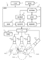
図1は、画像処理システム1を追跡システムに適用した場合の全体構成を示す。例えば、空港、港、商業施設、遊園地、病院、役所等の施設では、複数のカメラを用いて監視対象領域を監視する。
FIG. 1 shows an overall configuration when the
人物追跡システムとしての画像処理システム1は、例えば、複数の全方位カメラ10、演算部11、入力部12、表示部13、ハブ14、記録部15を備える。
The
演算部11は、メモリ、マイクロプロセッサ、入出力回路、通信回路(いずれも不図示)等を含むコンピュータシステムとして構成される。演算部11は、例えば、追跡部111、軌跡保存部112、軌跡連結部113、軌跡取得部114、設定部115、設定保存部116を備える。
The
全方位カメラ10(1)〜10(4)は、監視対象領域を撮影するための映像撮影手段である。図中では、4つのカメラを示すが、4個に限らない。画像処理システム1は、2個以上のカメラを使用可能であればよい。
The omnidirectional cameras 10 (1) to 10 (4) are video photographing means for photographing the monitoring target area. Although four cameras are shown in the figure, the number is not limited to four. The
以下では、特に区別しない場合、かっこ付きの数字を除いて説明する場合がある。例えば、カメラ10(1)〜10(4)をカメラ10と、視野100(1)〜100(4)を視野100と、視野重複領域101(1)〜101(3)を視野重複領域101と、それぞれ呼ぶ場合がある。
In the following description, unless otherwise distinguished, the description may be made excluding the numbers with parentheses. For example, the cameras 10 (1) to 10 (4) are the
各カメラ10の視野(撮影領域とも呼ぶ)100は、全ての監視領域を網羅する必要はないが、隣接するカメラ同士は、移動体3が認識可能な大きさで同時に両方のカメラに映るように、視野100が重複している必要がある。視野100の重複した領域を視野重複領域101と呼ぶ。
The field of view (also referred to as an imaging area) 100 of each
「内部パラメータ取得部」の例である入力部12は、カメラの設定に必要な情報を、画像処理システム1の設置作業を行うユーザから受け付ける装置である。ユーザは、例えば、カメラ10の内部パラメータを入力部12を介して演算部11へ入力する。さらに、座標を自動的に検知しない場合、ユーザは、静止マーカ2の座標や、視野重複領域101にいる人物3の座標を手動で入力してもよい。入力部12の例は後述するが、タッチパネル、キーボード、ポインティングデバイス、音声入力装置等を用いることができる。
The
表示部13は、演算部11で計算された静止マーカ2の座標や人物3の座標、人物3の移動軌跡等を表示する装置である。表示部13としては、例えば、ディスプレイやプリンタ等を用いることができる。
The
入力部12と表示部13とは、演算部11と何らかの通信規格を用いてデータを送受信できる装置であればよく、種類を問わない。
The
演算部11は、カメラ10から入力された画像や、入力部12から入力された座標あるいは自動検知された座標を使って、人物3の追跡や外部パラメータの計算を行う。演算部11は、メモリに格納された所定のコンピュータプログラムをマイクロプロセッサが実行することにより、各機能111〜116を実現する。以下、演算部11の実現する機能ブロックについて説明する。
The
追跡部111は、カメラ10で取得した画像を入力として、人物を追跡する。追跡部111は、所定の時間間隔で入力される画像から人物部分を検出し、検出した人物部分の画像上の座標を取得することにより、人物3を追跡する。人物3の追跡に使用する座標は、足下の座標または頭部の座標のいずれでもよい。
The
軌跡保存部112は、追跡部111で取得した座標と取得時刻および軌跡IDとを入力として、それらをデータベース等の保存手段(不図示)に保存する。座標データは、画像上の座標と世界座標とに分けて保存する。軌跡保存部112は、画像上の座標と世界座標とを対応づけられて保存する。また、軌跡を連結する際に、人物3の外見等の画像特徴量を用いる場合、軌跡保存部112は人物画像も保存する。
The
軌跡連結部113は、軌跡保存部112に保存された世界座標、画像特徴量あるいはそれら両方を用いて、それぞれのカメラ10の視野100に存在する同一人物の軌跡を連結する。軌跡連結部113は、連結した軌跡に対して、カメラ間で共通のグローバルIDを割り当て、世界座標と共に軌跡保存部112へ出力する。
The
軌跡取得部114は、設定部115が外部パラメータを計算する際に、人物3の座標を設定部115へ出力する。軌跡取得部114は、カメラ間の視野重複領域101にいる人物3の座標を取得するか、あるいは、入力部12から視野重複領域101にいる人物3の座標の入力を受け付けることができる。
The
設定部115は、軌跡取得部114から入力された座標情報と予め設定保存部116に保存された内部パラメータとを使って、カメラ10の外部パラメータを計算する。
The
設定保存部116は、ユーザから入力された内部パラメータや設定部115で計算された外部パラメータを、データベース等の保存手段に保存する。
The setting
ハブ14は、各カメラ10に電源を供給したり、各カメラ10から画像データを受信したりする装置である。ハブ14と各カメラ10とは、有線または無線のいずれでも接続することができる。ハブ14と各カメラ10とが無線で接続される場合、ハブ14は各カメラ10へ電源を供給する必要はない。
The
記録部15は、各カメラ10で撮影した画像データを記憶する装置である。記録部15は、所定期間の画像データを保存するように構成することができる。
The
図2のフローチャートは、演算部11の実施する外部パラメータ計算処理を示す。本処理は、ユーザの指示により開始される。ここでは、各カメラ10(1)〜10(4)のうち、カメラ10(1)を基準カメラとして選択する例を述べる。これに限らず、他のカメラ10(2)〜10(4)のいずれも基準カメラとして選択可能である。
The flowchart of FIG. 2 shows an external parameter calculation process performed by the
演算部11は、各カメラ10(1)〜10(4)のうち基準カメラ10(1)の内部パラメータを入力部12から取得する(S10)。ユーザが入力部12から入力した基準カメラ10(1)の内部パラメータは、設定保存部116に保存され、外部パラメータ計算の際に用いられる。
The
次に演算部11は、静止マーカ2を用いて、基準カメラ10(1)の外部パラメータを計算する(S11)。この計算には例えば、非特許文献2を適用可能である。
Next, the
ステップS11の処理により、世界座標系の原点および軸が決定され、基準カメラ10(1)の外部パラメータが計算される。 Through the processing in step S11, the origin and axis of the world coordinate system are determined, and the external parameters of the reference camera 10 (1) are calculated.
演算部11は、視野重複領域101へ移動した移動体3を検出する(S12)。移動体3は、基準カメラ10(1)以外の他の各カメラ10(2)〜10(4)の視野を順次通過する移動マーカである。移動マーカには、作業者等の人物やロボット等を用いることができる。
The calculating
演算部11は、視野重複領域101に入った移動体3の座標を用いて、他のカメラについての外部パラメータを計算する(S13)。全てのカメラ10について外部パラメータの計算が完了するまで、ステップS12,S13を繰り返す。演算部11は、全てのカメラ10の外部パラメータを計算して保存が完了すると、本処理を正常終了する。
The calculating
以後、画像処理システム1は、施設内を移動する人物の座標を正確に特定しながら追跡することができる。
Thereafter, the
基準カメラ10(1)以外の他のカメラ10(2)〜10(4)の外部パラメータの計算方法を説明する。 A method for calculating external parameters of the cameras 10 (2) to 10 (4) other than the reference camera 10 (1) will be described.
まず、世界座標系と画像上の座標の相互変換について説明する。世界座標系におけるカメラの位置を(Xcam,Ycam,Zcam)とし、この系におけるピッチ角、ロール角、ヨー角をそれぞれα、β、γとすると、カメラの外部パラメータEは以下のようになる。 First, mutual conversion between the world coordinate system and the coordinates on the image will be described. If the camera position in the world coordinate system is (X cam , Y cam , Z cam ), and the pitch angle, roll angle, and yaw angle in this system are α, β, and γ, respectively, the external parameter E of the camera is as follows: become.
![]()
![]()
外部パラメータEにおけるロール角β、ピッチ角α、ヨー角γの順番で回転させた場合の3×3の回転行列をR、座標系の基準を世界座標からカメラ座標に移動するための3次元の並進ベクトルをtとし、行列Mを以下のように定義する。 A 3 × 3 rotation matrix when rotating in the order of the roll angle β, pitch angle α, and yaw angle γ in the external parameter E, and a three-dimensional for moving the coordinate system reference from the world coordinates to the camera coordinates. Let the translation vector be t, and define the matrix M as follows.

回転行列Rおよび並進ベクトルtは、外部パラメータEから求まる。人物の世界座標系における座標をPw=[Xw,Yw,Zw]T、カメラ座標系における座標をPc=[Xc,Yc,Zc]Tとすると、世界座標からPwからカメラ座標Pcへの変換は以下のようになる。 The rotation matrix R and the translation vector t are obtained from the external parameter E. If the coordinates of the person in the world coordinate system are Pw = [Xw, Yw, Zw] T, and the coordinates in the camera coordinate system are Pc = [Xc, Yc, Zc] T , the conversion from the world coordinates to Pw to the camera coordinates Pc is It becomes as follows.
画像上の座標系における画像中心をp0=[u0,v0]T、人物の座標p=[u,v]Tとする。ここで、ρおよびrを以下のように定義する。 Assume that the image center in the coordinate system on the image is p 0 = [u 0 , v 0 ] T , and the human coordinates p = [u, v] T. Here, ρ and r are defined as follows.
![]()
![]()
カメラ座標Pcから人物座標pには、数6に示すように変換できる。 Conversion from the camera coordinates Pc to the person coordinates p can be performed as shown in Equation 6.
ただし、f(ρ)は、数7に示すように表される。
However, f (ρ) is expressed as shown in Equation 7.
![]()
![]()
f(ρ)を第何項までで表現するかは、必要精度により決定する。なお、数8は内部パラメータを示す。内部パラメータは予め計算されている。
The number of terms to express f (ρ) is determined by the required accuracy. Equation 8 represents an internal parameter. Internal parameters are calculated in advance.
![]()
![]()
以上の変換により、世界座標系の座標から画像上の座標へ変換できる。また上記の変換を逆に行うことで、画像上の座標から世界座標系の座標へ変換できる。ただし、画像上の座標から世界座標系の座標へ変換する場合、世界座標系における人物のZ軸方向の値であるZwは既知である必要がある。以下では上記の変換を用いてカメラの外部パラメータを求める方法を説明する。 With the above conversion, the coordinates in the world coordinate system can be converted into the coordinates on the image. Further, by performing the above conversion in reverse, the coordinates on the image can be converted into the coordinates of the world coordinate system. However, when converting from coordinates on the image to coordinates in the world coordinate system, Zw, which is a value in the Z-axis direction of the person in the world coordinate system, needs to be known. Hereinafter, a method of obtaining the external parameters of the camera using the above conversion will be described.
図3は、二つのカメラ間で外部パラメータを計算する際の模式図である。カメラ10(1)は、基準カメラである。カメラ10(2)は、移動体3を用いて外部パラメータを計算するカメラである。
FIG. 3 is a schematic diagram when calculating external parameters between two cameras. The camera 10 (1) is a reference camera. The camera 10 (2) is a camera that calculates external parameters using the moving
基準カメラ10(1)の外部パラメータは、事前に、静止マーカ2(1)および静止マーカ2(2)を用いて計算されている。基準カメラ10(1)の外部パラメータを計算する際に、世界座標系20が決定される。本実施例では、静止マーカ2(1)の位置に世界座標系20の原点を置いたが、世界座標系20の中で静止マーカの位置を一意に決定できればよく、どこに原点を置いてもよい。
External parameters of the reference camera 10 (1) are calculated in advance using the stationary marker 2 (1) and the stationary marker 2 (2). When calculating the external parameters of the reference camera 10 (1), the world coordinate
この世界座標系20をもとに、カメラ10(2)の外部パラメータを計算する。カメラ10(2)の外部パラメータは、世界座標系20におけるカメラの位置(Xcam1,Ycam1,Zcam1)およびこの系におけるピッチ角α1、ロール角β1、ヨー角γ1の六つとし、以下のように定義する。
Based on the world coordinate
![]()
![]()
この外部パラメータE1を計算するために、視野重複領域101に移動マーカとしての人物3を通過させる。本実施例では、通過する人物3の身長Hがわかっている場合について説明する。移動マーカとしての人物3の身長がわかっていない場合は、足下の座標のみを使って外部パラメータを計算することも可能である。身長Hの値は、実際の長さと座標系におけるスケールとの対応により変化する。身長が既知の場合、より多くの座標が観測できるため、外部パラメータ計算の精度を高めることができる。
In order to calculate the external parameter E1, the
ある時刻τにおいて、人物3が基準カメラ10(1)と外部パラメータの計算対象であるカメラ10(2)との視野重複領域101(1)の位置にいる。図3では、この人物に符号3(1)を与える。
At a certain time τ, the
人物3(1)の足下の座標は、座標30(1)(Pf1=[Xwp1,Ywp1,0]T)である。人物3(1)の頭部の座標は、座標31(1)(Ph1=[Xwp1,Ywp1,H]T)である。 Feet of coordinates of the person 3 (1) are the coordinates 30 (1) (P f1 = [X wp1, Y wp1, 0] T). The coordinates of the head of the person 3 (1) are coordinates 31 (1) ( Ph1 = [ Xwp1 , Ywp1 , H] T ).
時刻τ+1に、人物3(1)が視野重複領域101(1)内で移動したとする。図3では、この人物に符号3(2)を与える。 It is assumed that the person 3 (1) moves within the field-of-view overlap region 101 (1) at time τ + 1. In FIG. 3, reference numeral 3 (2) is given to this person.
人物3(2)の足下の座標は、座標30(2)(Pf2=[Xwp2,Ywp2,0]T)である。人物3(2)の頭部の座標は、座標31(2)(Ph2=[Xwp2,Ywp2,H]T)となる。 The feet of the coordinates of the person 3 (2), the coordinates 30 (2) (P f2 = [X wp2, Y wp2, 0] T). Head of the coordinates of the person 3 (2) becomes the coordinates 31 (2) (P h2 = [X wp2, Y wp2, H] T).
ここでは、人物3は直立しているか、もしくは移動中においても身長が一定であるとしている。これに代えて、歩行モデルから身長の減衰量を算出し、正確な頭部の位置を求める方法もある。
Here, it is assumed that the
これらの座標を基準カメラ10(1)の画像上の座標から求め、更に求めた世界座標をカメラ10(2)の画像上の座標に変換し、カメラ10(2)に映った実際の座標との誤差が最小になるようにして、カメラ10(2)の外部パラメータE1を計算する。 These coordinates are obtained from the coordinates on the image of the reference camera 10 (1), and the obtained world coordinates are converted into the coordinates on the image of the camera 10 (2), and the actual coordinates reflected in the camera 10 (2) The external parameter E1 of the camera 10 (2) is calculated in such a manner that the error of is minimized.
図4は、基準カメラ10(1)およびカメラ10(2)のカメラ画像を示す。画像40(1)は、カメラ10(1)の撮影した画像である。画像40(2)は、カメラ10(2)の撮影した画像である。 FIG. 4 shows camera images of the reference camera 10 (1) and the camera 10 (2). The image 40 (1) is an image taken by the camera 10 (1). The image 40 (2) is an image taken by the camera 10 (2).
時刻τにおいて、基準カメラ10(1)およびカメラ10(2)とに映る人物3は、それぞれカメラ画像40(1)の3(11)およびカメラ画像40(2)の3(21)に対応する。
At time τ, the
時刻τ+1において、基準カメラ10(1)とカメラ10(2)とに映る人物3は、それぞれカメラ画像40(1)の3(12)およびカメラ画像40(2)の3(22)に対応する。
At time τ + 1, the
ここで、座標30(11)(pi1f1)は、時刻τにおける人物3(11)の足下の座標である。座標30(12)(pi1f2)は、時刻τ+1における人物3(12)の足下の座標である。座標30(21)(pi2f1)は、時刻τにおける人物3(21)の足下の座標である。座標31(21)(pi2h1)は、時刻τにおける人物3(21)の頭部の座標である。座標30(22)(pi2h2)は、時刻τ+1における人物3(22)の足下の座標である。座標31(22)(pi2h2)は、時刻τ+1における人物3(22)の頭部の座標である。これらの座標は、人物検出手法を用いて自動的に検出してもよいし、ユーザが入力部12から手動で入力してもよい。
Here, the coordinates 30 (11) (p i1f1 ) are the coordinates of the feet of the person 3 (11) at the time τ. The coordinates 30 (12) (p i1f2 ) are the coordinates of the feet of the person 3 (12) at time τ + 1. The coordinates 30 (21) (p i2f1 ) are the coordinates of the feet of the person 3 (21) at the time τ. The coordinates 31 (21) (p i2h1 ) are the coordinates of the head of the person 3 (21) at the time τ. The coordinates 30 (22) (p i2h2 ) are the coordinates of the feet of the person 3 (22) at the time τ + 1. The coordinates 31 (22) (p i2h2 ) are the coordinates of the head of the person 3 (22) at time τ + 1. These coordinates may be detected automatically using a person detection method, or may be manually input from the
基準カメラ10(1)の画像上の座標を、世界座標に変換する。以下では、座標pi1f1から世界座標Pf1に変換する例を用いて説明する。数6より、pi1f1は、カメラ座標系の座標Pcf1=[Xcf1,Ycf1,Zcf1]Tに、数10に示すように変換される。
The coordinates on the image of the reference camera 10 (1) are converted into world coordinates. Below, it demonstrates using the example converted from coordinate p i1f1 to world coordinate P f1 . From Equation 6, p i1f1 is converted into coordinates P cf1 = [X cf1 , Y cf1 , Z cf1 ] T in the camera coordinate system as shown in Equation 10.
ここで数11のように定義すると、Xcf1、Ycf1、Zcf1は、rcf1の一次式となる。数3により、Pcf1は、数12に示すようにして世界座標Pf1に変換される。
Here, when defined as in Equation 11, X cf1 , Y cf1 , and Z cf1 are linear expressions of r cf1 . From Equation 3, P cf1 is converted to world coordinates P f1 as shown in Equation 12.
![]()
![]()
Pcf1の座標の値は、rcf1の一次式で表されているので、Pf1もrcf1の一次式で表される。Pf1のZ座標は0であるので、rcf1について解ける。従ってPf1のX座標およびY座標が求まる。 Coordinate values of P cf1 is because it is represented by a linear equation of r cf1, P f1 is also represented by a linear equation of r cf1. Since the Z coordinate of P f1 is 0, it can be solved for r cf1 . Therefore, the X coordinate and Y coordinate of P f1 are obtained.
Ph1は、Pf1のZ座標を人物の身長Hとした座標となる。上記の操作により、画像40(1)で検出した人物の足下の座標を全て世界座標に変換し、人の身長を用いて足下の座標に対する頭部の座標を全て計算する。 P h1 is a coordinate with the Z coordinate of P f1 as the person's height H. By the above operation, all the coordinates of the feet of the person detected in the image 40 (1) are converted into world coordinates, and all the coordinates of the head with respect to the coordinates of the feet are calculated using the height of the person.
変換された世界座標は、数3と数6とカメラ10(2)の外部パラメータE1とを用いて、画像40(2)における画像上の座標に変換する。この座標は、パラメータE1の関数として表現できる。pi1f1およびpi1h1を、画像40(2)の画像上の座標に変換したときの座標を数13のように表現する。
The converted world coordinates are converted into the coordinates on the image in the image 40 (2) using the
![]()
![]()
実際に観測される座標は、pi2f1およびpi2h1であり、誤差が生じる。パラメータE1は、この誤差を全ての点について計算し、誤差を最小にするような値を求める。すなわち、以下の数14を最小にするE1を求める。
The actually observed coordinates are p i2f1 and p i2h1 , and an error occurs. The parameter E1 calculates this error for all points and obtains a value that minimizes the error. That is, E1 that minimizes the following
![]()
![]()
最小化するE1を求めるアルゴリズムには、例えば、Gauss−Newton法等を用いることができる。 As an algorithm for obtaining E1 to be minimized, for example, Gauss-Newton method or the like can be used.
以上の操作により、基準カメラ10(1)に隣接するカメラ10(2)の外部パラメータを計算できる。また、外部パラメータの計算が終了したカメラ10(2)においては、画像上の座標から世界座標に変換できる。したがって、カメラ10(2)に隣接するカメラ10(3)の外部パラメータも、上記の操作により計算することできる。 With the above operation, the external parameters of the camera 10 (2) adjacent to the reference camera 10 (1) can be calculated. In addition, in the camera 10 (2) for which the calculation of the external parameters has been completed, the coordinates on the image can be converted into world coordinates. Therefore, the external parameters of the camera 10 (3) adjacent to the camera 10 (2) can also be calculated by the above operation.
従って、本実施例では、基準カメラ10(1)以外の他の各カメラ10(2)〜10(4)では、静止マーカ2を置くことなく、外部パラメータを計算することができ、設定作業時のユーザの作業負担を軽減することができる。
Therefore, in this embodiment, the external parameters can be calculated without placing the
なお、上記の方法では、移動体3が視野重複領域101を通過する際に、同一人物であるかを特定する必要がある。そこで以下に、人物の特定法の例を説明する。
In the above method, it is necessary to specify whether the moving
図5は、設定画面41の例を示す。設定部115は、設定モードを備えている。例えば、ユーザは、表示部13に表示されるメニューから設定モードを指定することで、画像処理システム1を設定モードへ移行させることができる。
FIG. 5 shows an example of the
図5では、設定モード中に同一人物の特定を手動で行う例を示す。設定画面41は、例えば、一つめのカメラの画像40(1)と、二つめのカメラの画像40(2)とを並べて表示する。さらに、設定画面41は、画像のフレームを一つ前に戻すボタン411と、フレームを一つ先に進めるボタン412と、設定モードを開始させるボタン413と、設定モードを終了させるボタン414を備える。画面には、座標を指定するポインタ415が表示される。なお、図5では、一つ目のカメラ画像40(1)に人物3(1)が映っており、二つ目のカメラ画像40(2)に人物3(2)が映っている。符号30は、指定された人物3(1)の足下の座標を示す。
FIG. 5 shows an example in which the same person is manually specified during the setting mode. The
カメラ画像40(1)とカメラ画像40(2)には、それぞれ同一時刻の画像が表示されている。 In the camera image 40 (1) and the camera image 40 (2), images at the same time are displayed.
ユーザが設定モード開始ボタン413を操作すると、設定モードに移行する。ユーザは、ボタン411またはボタン412を操作しながら、ある間隔で各カメラ画像40(1),40(2)に映る同一人物の座標を、ポインタ415により座標30のように指定していく。ユーザが最後に終了ボタン414を操作すると、指定した座標30により外部パラメータの計算が始まる。
When the user operates the setting
この方法では、ユーザが手動で座標30を入力するため、移動体3の特定時の座標誤差を低減することができる。また図5の方法によれば、移動体3としての人物を検知できないという事態が生じないため、高い信頼性で外部パラメータを計算できる。なお、図5では、二つのカメラ画像40(1),40(2)のみを表示する例を示したが、これに限らず、三台以上のカメラ画像を同時に表示してもよい。
In this method, since the user manually inputs the
図6は、設定モード中に、唯一の人物3をカメラ間に通過させ、各カメラの映像から人物3を自動検出することにより、同一人物を特定する例を示す。
FIG. 6 shows an example in which the same person is specified by passing only one
設定画面42は、複数のカメラ画像40(1),40(2)を並べて表示する。設定画面42は、設定モード開始ボタン421と、設定モード終了ボタン422と、人物が検出されたことを通知するためのアラート423,424とを含む。
The
一つめのカメラ画像40(1)には、移動体としての唯一の人物3(1)が映されている。その人物3(1)は、足下の座標30(1)と頭部の座標31(1)を持つ。二つめのカメラ画像40(2)にも、人物3(2)が映されている。人物3(2)は、足下の座標30(2)と頭部の座標31(2)を持つ。 In the first camera image 40 (1), the only person 3 (1) as a moving object is shown. The person 3 (1) has foot coordinates 30 (1) and head coordinates 31 (1). The person 3 (2) is also reflected in the second camera image 40 (2). The person 3 (2) has foot coordinates 30 (2) and head coordinates 31 (2).
まず、ユーザが開始ボタン421を操作すると、画像処理システム1は設定モードに移行する。
First, when the user operates the
設定モードへ移行した後で、視野重複領域101に唯一の人物3を通過させ、その人物3の座標を自動検出する。同一時刻に取得した座標は、同一人物の座標であると判断し、保存しておく。
After shifting to the setting mode, the
最後に、ユーザが終了ボタン422を押すと、外部パラメータの計算が始まる。図6で述べた方法を用いると、移動体としての人物の座標を自動で検知できる。したがって、図6の例は、図5に示した例と比較して、設定作業時の負担をさらに軽減できる。なお、図6の場合も、設定モードの開始から設定モードの終了まで、唯一の人物を三台以上のカメラ間で通過させて、外部パラメータを計算してもよい。
Finally, when the user presses the
図7は、人物の外見等の画像特徴量を用いて、人物を自動的に特定する例を示す。図7の例では、設定モードは設けられていない。図7の例では、人物を追跡しながら画像特徴量を用いて、同一人物であるか特定する。 FIG. 7 shows an example in which a person is automatically specified using an image feature amount such as the appearance of the person. In the example of FIG. 7, the setting mode is not provided. In the example of FIG. 7, it is specified whether or not they are the same person using the image feature amount while tracking the person.
設定画面43には、人物3(1)の映ったカメラ画像40(1)と、人物3(2)の映ったカメラ画像40(2)とが並んで表示されている。点線の矩形431(1)は、一つ目のカメラ画像40(1)において、同一人物であることを特定したことを示す表示要素である。同様に、点線の矩形431(2)は、二つ目のカメラ画像40(2)において、同一人物を特定したことを示す表示要素である。人物3(1)の足下の座標30(1)および頭部の座標31(1)は、カメラ画像40(1)から自動検出される。人物3(2)の足下の座標30(2)および頭部の座標31(2)は、カメラ画像40(2)から自動検出される。
On the
図7に示す例では、カメラ画像内で人物を自動検出し、検出した人物の画像特徴量を計算する。そして、外部パラメータが計算されたカメラと計算されていないカメラとについて、同一時刻に映っている人物の画像特徴量を比較することにより、同一人物であるか否か判定する。 In the example shown in FIG. 7, a person is automatically detected in the camera image, and the image feature amount of the detected person is calculated. And it is determined whether it is the same person by comparing the image feature-value of the person who is reflected in the same time about the camera with which the external parameter was calculated, and the camera with which it is not calculated.
同一人物と判定された場合は、座標を保存する。同一と判定された人物が検出されなくなった際に、外部パラメータの計算を開始する。この方法では、設定モードを設ける必要がなく、図5および図6で述べた方法と比較して、簡潔に外部パラメータを計算することができる。なお、図7の例においても、三台以上のカメラ画像を同時に表示して処理してもよい。 If it is determined that the person is the same person, the coordinates are stored. When the person determined to be the same is no longer detected, the calculation of the external parameter is started. In this method, it is not necessary to provide a setting mode, and the external parameters can be calculated in a simple manner as compared with the methods described in FIGS. In the example of FIG. 7, three or more camera images may be simultaneously displayed and processed.
このように構成される本実施例によれば、複数のカメラのそれぞれに静止マーカ2を設置して外部パラメータを計算する必要がなく、カメラの設置時の設定作業の効率を向上することができる。
According to the present embodiment configured as described above, it is not necessary to calculate the external parameter by installing the
本実施例によれば、最初に基準となるカメラについてのみ静止マーカ2を用いて外部パラメータを演算すれば、他の各カメラについては、人物やロボット等の移動体3を視野重複領域101を通過するように移動させるだけで、外部パラメータを計算することができ、カメラを設定するユーザの使い勝手と作業効率を向上することができる。
According to the present embodiment, if the external parameters are calculated using the
図8〜図10を用いて、第2実施例を説明する。本実施例を含む以下の各実施例では、第1実施例との相違を中心に説明する。 A second embodiment will be described with reference to FIGS. In the following embodiments including the present embodiment, differences from the first embodiment will be mainly described.
本実施例では、第1実施例の外部パラメータ計算と同時に、外部パラメータを用いて変換する世界座標系から監視対象の施設内の平面図を作成する例を説明する。 In the present embodiment, an example will be described in which a plan view in a monitored facility is created from a world coordinate system that is converted using external parameters simultaneously with the external parameter calculation of the first embodiment.
第1実施例の方法を用いると、外部パラメータの計算と同時に、移動体3の世界座標を得ることができる。本実施例では、移動体3の世界座標を用いて、移動体3の移動領域を検出し、平面図の移動可能領域を示す図の作成を支援する。なお、外部パラメータの計算手順については、第1実施例と同様である。
When the method of the first embodiment is used, the world coordinates of the moving
図8は、本実施例に係る画像処理システム1aの全体構成を示す。画像処理システム1aは、第1実施例で述べた構成に対して、移動領域検出部117が追加されている。移動領域検出部117は、軌跡保存部112から軌跡を受け取り、その軌跡から移動領域を計算して、設定部115へ出力する。本実施例では、移動体として、自動走行するロボット3aを用いる。ロボット3aは、障害がないときは直進し、壁等の障害物に衝突するとランダムに方向転換して走行を継続する。以下、移動領域の検出法を説明する。
FIG. 8 shows the overall configuration of the image processing system 1a according to the present embodiment. In the image processing system 1a, a moving
図9に示すように、移動体3aは、障害物に接触しないかぎり直進し、障害物に接触するとランダムに方向転換して直進する。したがって、ロボット3aの軌跡から、ロボット3aの移動可能な領域を検出することができる。なお、ロボット3aに代えて、人がロボット3aのような動作で歩行してもよい。
As shown in FIG. 9, the moving
図9の検出画面44は、世界座標系におけるXY平面を示す。検出画面44には、ロボット3aの移動軌跡441と、軌跡の折り返し地点について最近傍点同士を結んだ線442とが表示されている。
The
図9に示すように、ロボット3aを床面上でランダムに走行させ、世界座標系における軌跡を取得することで、移動領域を検出する。軌跡441に示すように、ロボット3aを長距離走らせることで、移動可能領域を埋め尽くすようにして軌跡が発生する。
As shown in FIG. 9, the
また、ロボット3aは、障害物に衝突すると方向転換するため、軌跡における折り返し点の最近傍点同士を接続することで、移動領域を囲む線442を描くことができる。ロボット3aに十分な距離を走らせた後で、線442を軌跡全体で作成することにより、施設の平面図の移動可能領域を生成することができる。
Further, since the
図10は、移動体として人物を用い、世界座標系の軌跡において閉領域を形成することにより、移動領域を検出する例を示す。なお、同様の動作をロボットが行うことで、同様の効果が得られる。 FIG. 10 shows an example in which a moving area is detected by using a person as a moving body and forming a closed area in the locus of the world coordinate system. A similar effect can be obtained when the robot performs the same operation.
図10の検出画面45は、世界座標系におけるXY平面を示す。検出画面45には、人物の移動軌跡451と、移動軌跡451によって決定された移動領域452とが表示されている。
The
人物は、軌跡451に示すように、閉領域を形成するように歩く。閉領域が完成するとその領域は移動可能領域452として決定される。一個あるいは複数個の閉領域を用いて、監視対象の施設内の全領域を埋め尽くすように移動軌跡を発生させる。これにより、施設内の平面図の移動可能領域を生成することができる。
A person walks so as to form a closed region as indicated by a
図11を用いて、第3実施例を説明する。本実施例の各カメラ10aは、撮像部110と演算部11aとを備える。演算部11aは、上述した各機能11〜116のほかに、他のカメラ等と通信する通信部118を備える。通信部118は、無線または有線の通信ネットワークCNを介して、他のカメラ10aまたは端末5と通信する。
A third embodiment will be described with reference to FIG. Each camera 10a of the present embodiment includes an
端末5は、ユーザが情報を入力したり、カメラ10aの画像を確認したりするためのコンピュータ端末である。 The terminal 5 is a computer terminal for a user to input information and confirm an image of the camera 10a.
各カメラ10aは、軌跡保存部112の保持する軌跡データを、通信部118および通信ネットワークCNを介して、隣接するカメラ10aの設定部115へ引き渡す。これにより、本実施例では、各カメラ10aを統括する演算部11を用いずに、各カメラ10a間で情報をやり取りすることにより、視野内の移動体を特定して追跡し、座標を算出することができる。
Each camera 10a passes the trajectory data held by the
本実施例では、高機能化されたカメラ10aを用いるため、設定を一元管理する演算部11を設ける必要がない。したがって、画像処理システム1の構成を簡素化でき、取付作業の作業性を改善することができる。
In the present embodiment, since the highly functional camera 10a is used, it is not necessary to provide the
なお、本発明は上記各実施例に限定されるものではなく、様々な変形例が含まれる。例えば、上記した実施例は本発明を分かりやすく説明するために詳細に説明したものであり、必ずしも説明した全ての構成を備えるものに限定されるものではない。また、ある実施例の構成の一部を他の実施例の構成に置き換えることが可能であり、また、ある実施例の構成に他の実施例の構成を加えることも可能である。また、各実施例の構成の一部について、他の構成の追加・削除・置換をすることが可能である。 In addition, this invention is not limited to said each Example, Various modifications are included. For example, the above-described embodiments have been described in detail for easy understanding of the present invention, and are not necessarily limited to those having all the configurations described. Further, a part of the configuration of one embodiment can be replaced with the configuration of another embodiment, and the configuration of another embodiment can be added to the configuration of one embodiment. Further, it is possible to add, delete, and replace other configurations for a part of the configuration of each embodiment.
また、上記の各構成は、それらの一部又は全部が、ハードウェアで構成されても、プロセッサでプログラムが実行されることにより実現されるように構成されてもよい。また、制御線や情報線は説明上必要と考えられるものを示しており、製品上必ずしも全ての制御線や情報線を示しているとは限らない。実際には殆ど全ての構成が相互に接続されていると考えてもよい。 In addition, each of the above-described configurations may be configured such that some or all of them are configured by hardware, or are implemented by executing a program by a processor. Further, the control lines and information lines indicate what is considered necessary for the explanation, and not all the control lines and information lines on the product are necessarily shown. Actually, it may be considered that almost all the components are connected to each other.
1,1a:画像処理システム、2:静止マーカ、3,3a:移動体、10,10a:カメラ、11,11a:演算部、12:入力部、13:表示部、111:追跡部、112:軌跡保存部、113:軌跡連結部、114:軌跡取得部、115:設定部、116:設定保存部、117:移動領域検出部、118:通信部
DESCRIPTION OF
Claims (12)
前記複数のカメラは、隣接するカメラ同士の視野の重複する視野重複領域が形成されるようにして設置されており、
前記各カメラに固有の内部パラメータを取得する内部パラメータ取得部と、
移動体を追跡して、移動体の時刻および座標を出力する追跡部と、
前記移動体が前記視野重複領域に存在するときの、前記移動体の座標を取得することにより、前記移動体の軌跡を取得する軌跡取得部と、
前記移動体の画像特徴量に基づいて、隣接するカメラのうち一方のカメラで撮影された移動体の画像と他方のカメラで撮影された移動体の画像とを比較することにより、前記移動体の軌跡を連結する軌跡連結部と、
前記軌跡取得部により取得された座標と前記内部パラメータとを用いて、前記座標に対応するカメラの取付状態に関する外部パラメータを設定値として算出する設定部と、
前記取得された内部パラメータと前記設定部により算出された外部パラメータとを対応づけて保存する設定保存部と、
を備える、
画像処理システム。 An image processing system for processing images taken by a plurality of cameras,
The plurality of cameras are installed in such a manner that a field-of-view overlap region is formed in which the fields of view of adjacent cameras overlap.
An internal parameter acquisition unit for acquiring internal parameters specific to each camera;
A tracking unit that tracks the moving object and outputs the time and coordinates of the moving object;
A trajectory acquisition unit for acquiring a trajectory of the moving object by acquiring the coordinates of the moving object when the moving object exists in the visual field overlap region;
Based on the image feature amount of the moving body, by comparing an image of the moving body captured by one of the adjacent cameras and an image of the moving body captured by the other camera, A trajectory link for connecting the trajectories;
Using the coordinates acquired by the trajectory acquisition unit and the internal parameters, a setting unit that calculates external parameters related to the camera mounting state corresponding to the coordinates as set values;
A setting storage unit that stores the acquired internal parameter and the external parameter calculated by the setting unit in association with each other;
Comprising
Image processing system.
前記各カメラのうち所定のカメラの外部パラメータを、前記所定のカメラの視野に設けられるマーカに基づいて算出し、
前記各カメラのうち前記所定のカメラ以外の他のカメラの外部パラメータについては、前記軌跡取得部により取得される前記視野重複領域での前記移動体の座標を用いて算出する、
請求項1に記載の画像処理システム。 The setting unit
An external parameter of a predetermined camera among the cameras is calculated based on a marker provided in the visual field of the predetermined camera,
The external parameters of the cameras other than the predetermined camera among the cameras are calculated using the coordinates of the moving body in the visual field overlap region acquired by the trajectory acquisition unit.
The image processing system according to claim 1.
請求項2に記載の画像処理システム。 When the setting mode is activated, the setting unit acquires the coordinates of the moving object existing in the visual field overlap region.
The image processing system according to claim 2.
前記設定部は、前記設定モード中に、前記視野重複領域に存在する前記移動体の座標を前記入力部から取得する、
請求項3に記載の画像処理システム。 It further includes an input unit for inputting information from the user,
The setting unit acquires the coordinates of the moving object existing in the visual field overlap region from the input unit during the setting mode.
The image processing system according to claim 3.
前記設定部は、前記軌跡取得部から前記移動体の座標を取得する、
請求項3に記載の画像処理システム。 The trajectory acquisition unit acquires the coordinates of the moving object existing in the visual field overlap region during the setting mode,
The setting unit acquires the coordinates of the moving body from the trajectory acquisition unit.
The image processing system according to claim 3.
請求項5に記載の画像処理システム。 The moving body is configured as the only moving body that passes through each field-of-view overlap region between the adjacent cameras during the setting mode,
The image processing system according to claim 5.
前記軌跡取得部は、前記軌跡連結部が特定した同一人物の視野重複領域における座標を取得する、
請求項2に記載の画像処理システム。 The moving body is a person,
The trajectory acquisition unit acquires coordinates in a field overlap region of the same person specified by the trajectory connection unit;
The image processing system according to claim 2.
請求項2に記載の画像処理システム。 The moving body is a robot that automatically avoids obstacles and travels.
The image processing system according to claim 2.
前記設定部は、前記移動領域検出部により検出される前記移動領域を用いて、前記各カメラの撮影範囲の平面図の作成を支援する情報を出力する、
請求項2に記載の画像処理システム。 A moving area detecting unit for detecting a moving area of the moving body;
The setting unit outputs information that supports creation of a plan view of the shooting range of each camera using the moving region detected by the moving region detection unit.
The image processing system according to claim 2.
請求項9に記載の画像処理システム。 The moving area detecting unit detects the moving area by detecting a turning point of the moving body from a trajectory of the moving body;
The image processing system according to claim 9.
請求項9に記載の画像処理システム。 The moving area detecting unit detects the moving area by detecting a closed area formed from a trajectory of the moving body;
The image processing system according to claim 9.
前記複数のカメラは、隣接するカメラ同士の視野の重複する視野重複領域が形成されるようにして設置されており、
前記各カメラに固有の内部パラメータを取得し、
前記各カメラのうち所定のカメラの外部パラメータを、前記所定のカメラの視野に設けられるマーカに基づいて算出し、
前記所定のカメラの視野から隣接するカメラの視野へ移動する移動体を追跡して、移動体の時刻および座標を取得し、
前記移動体が前記視野重複領域に存在するときの、前記移動体の座標を取得することにより、前記移動体の軌跡を取得し、
前記移動体の画像特徴量に基づいて、隣接するカメラのうち一方のカメラで撮影された移動体の画像と他方のカメラで撮影された移動体の画像とを比較することにより、前記移動体の軌跡を連結し、
前記取得された座標と前記内部パラメータとから、前記座標に対応するカメラの取付状態に関する外部パラメータを設定値として算出し、
前記内部パラメータと前記外部パラメータとを対応づけて保存し、
前記所定のカメラ以外の他のカメラの外部パラメータを、前記視野重複領域における前記移動体の座標を用いて算出する、
画像処理システムの設定方法。 An image processing system setting method for processing images taken by a plurality of cameras,
The plurality of cameras are installed in such a manner that a field-of-view overlap region is formed in which the fields of view of adjacent cameras overlap.
Get internal parameters specific to each camera,
An external parameter of a predetermined camera among the cameras is calculated based on a marker provided in the visual field of the predetermined camera,
Tracking a moving body that moves from the field of view of the predetermined camera to the field of view of an adjacent camera to obtain the time and coordinates of the moving body;
By obtaining the coordinates of the moving body when the moving body is present in the visual field overlap region, the trajectory of the moving body is obtained,
Based on the image feature amount of the moving body, by comparing an image of the moving body captured by one of the adjacent cameras and an image of the moving body captured by the other camera, Connect the trajectories,
From the acquired coordinates and the internal parameters, an external parameter relating to the camera mounting state corresponding to the coordinates is calculated as a set value,
The internal parameters and the external parameters are stored in association with each other,
An external parameter of a camera other than the predetermined camera is calculated using the coordinates of the moving body in the visual field overlap region.
How to set up an image processing system.
Priority Applications (1)
| Application Number | Priority Date | Filing Date | Title |
|---|---|---|---|
| JP2017162336A JP2019041261A (en) | 2017-08-25 | 2017-08-25 | Image processing system and setting method of image processing system |
Applications Claiming Priority (1)
| Application Number | Priority Date | Filing Date | Title |
|---|---|---|---|
| JP2017162336A JP2019041261A (en) | 2017-08-25 | 2017-08-25 | Image processing system and setting method of image processing system |
Publications (1)
| Publication Number | Publication Date |
|---|---|
| JP2019041261A true JP2019041261A (en) | 2019-03-14 |
Family
ID=65727248
Family Applications (1)
| Application Number | Title | Priority Date | Filing Date |
|---|---|---|---|
| JP2017162336A Pending JP2019041261A (en) | 2017-08-25 | 2017-08-25 | Image processing system and setting method of image processing system |
Country Status (1)
| Country | Link |
|---|---|
| JP (1) | JP2019041261A (en) |
Cited By (11)
| Publication number | Priority date | Publication date | Assignee | Title |
|---|---|---|---|---|
| WO2020194486A1 (en) * | 2019-03-26 | 2020-10-01 | 日本電気株式会社 | Calibration device, calibration method, and non-transitory computer readable medium having program stored thereupon |
| CN112102308A (en) * | 2020-09-25 | 2020-12-18 | 研祥智能科技股份有限公司 | Image splicing method and system and product defect detection method and system |
| JP2021033785A (en) * | 2019-08-27 | 2021-03-01 | 富士通クライアントコンピューティング株式会社 | Information processing apparatus and program |
| CN112598706A (en) * | 2020-12-21 | 2021-04-02 | 西北工业大学 | Multi-camera moving target three-dimensional trajectory reconstruction method without accurate time-space synchronization |
| JP2021069079A (en) * | 2019-10-28 | 2021-04-30 | 富士通クライアントコンピューティング株式会社 | Information processing system, information processing device, and program |
| JPWO2021090467A1 (en) * | 2019-11-08 | 2021-05-14 | ||
| CN113628243A (en) * | 2020-05-08 | 2021-11-09 | 广州海格通信集团股份有限公司 | Motion trajectory acquisition method and device, computer equipment and storage medium |
| JP2022032114A (en) * | 2020-08-11 | 2022-02-25 | トヨタ自動車株式会社 | Calibration system, calibration method, and calibration program |
| JP2022051683A (en) * | 2020-09-22 | 2022-04-01 | グラスパー テクノロジーズ エーピーエス | Concept of generating training data and training machine learning model for use in re-identification |
| CN114630024A (en) * | 2022-01-21 | 2022-06-14 | 北京航空航天大学 | Retina-imitating non-uniform imaging method based on array camera system |
| JP7414587B2 (en) | 2020-02-28 | 2024-01-16 | 株式会社東芝 | Monitoring method and device |
Citations (6)
| Publication number | Priority date | Publication date | Assignee | Title |
|---|---|---|---|---|
| JP2002005625A (en) * | 2000-06-27 | 2002-01-09 | Atr Media Integration & Communications Res Lab | Automatic calibrating method of camera |
| JP2004334393A (en) * | 2003-05-02 | 2004-11-25 | Canon Inc | Image processing method and apparatus thereof |
| JP2005233639A (en) * | 2004-02-17 | 2005-09-02 | Mitsubishi Electric Corp | Stereoscopic camera system and method for camera-to-camera calibration of the system |
| JP2010244326A (en) * | 2009-04-07 | 2010-10-28 | Alpine Electronics Inc | In-vehicle circumference image display device |
| JP2016080550A (en) * | 2014-10-17 | 2016-05-16 | オムロン株式会社 | Area information estimation device, area information estimation method and air conditioner |
| JP2016085602A (en) * | 2014-10-27 | 2016-05-19 | 株式会社日立製作所 | Sensor information integrating method, and apparatus for implementing the same |
-
2017
- 2017-08-25 JP JP2017162336A patent/JP2019041261A/en active Pending
Patent Citations (6)
| Publication number | Priority date | Publication date | Assignee | Title |
|---|---|---|---|---|
| JP2002005625A (en) * | 2000-06-27 | 2002-01-09 | Atr Media Integration & Communications Res Lab | Automatic calibrating method of camera |
| JP2004334393A (en) * | 2003-05-02 | 2004-11-25 | Canon Inc | Image processing method and apparatus thereof |
| JP2005233639A (en) * | 2004-02-17 | 2005-09-02 | Mitsubishi Electric Corp | Stereoscopic camera system and method for camera-to-camera calibration of the system |
| JP2010244326A (en) * | 2009-04-07 | 2010-10-28 | Alpine Electronics Inc | In-vehicle circumference image display device |
| JP2016080550A (en) * | 2014-10-17 | 2016-05-16 | オムロン株式会社 | Area information estimation device, area information estimation method and air conditioner |
| JP2016085602A (en) * | 2014-10-27 | 2016-05-19 | 株式会社日立製作所 | Sensor information integrating method, and apparatus for implementing the same |
Cited By (20)
| Publication number | Priority date | Publication date | Assignee | Title |
|---|---|---|---|---|
| JPWO2020194486A1 (en) * | 2019-03-26 | 2021-12-23 | 日本電気株式会社 | Calibration equipment, calibration method, and program |
| JP7283535B2 (en) | 2019-03-26 | 2023-05-30 | 日本電気株式会社 | CALIBRATION DEVICE, CALIBRATION METHOD, AND PROGRAM |
| US20220156977A1 (en) * | 2019-03-26 | 2022-05-19 | Nec Corporation | Calibration apparatus, calibration method, and non-transitory computer readable medium storing program |
| WO2020194486A1 (en) * | 2019-03-26 | 2020-10-01 | 日本電気株式会社 | Calibration device, calibration method, and non-transitory computer readable medium having program stored thereupon |
| JP2021033785A (en) * | 2019-08-27 | 2021-03-01 | 富士通クライアントコンピューティング株式会社 | Information processing apparatus and program |
| JP2021069079A (en) * | 2019-10-28 | 2021-04-30 | 富士通クライアントコンピューティング株式会社 | Information processing system, information processing device, and program |
| JPWO2021090467A1 (en) * | 2019-11-08 | 2021-05-14 | ||
| JP7277829B2 (en) | 2019-11-08 | 2023-05-19 | 日本電信電話株式会社 | Camera parameter estimation device, camera parameter estimation method and camera parameter estimation program |
| WO2021090467A1 (en) * | 2019-11-08 | 2021-05-14 | 日本電信電話株式会社 | Camera parameter estimation device, camera parameter estimation method, and camera parameter estimation program |
| JP7414587B2 (en) | 2020-02-28 | 2024-01-16 | 株式会社東芝 | Monitoring method and device |
| CN113628243A (en) * | 2020-05-08 | 2021-11-09 | 广州海格通信集团股份有限公司 | Motion trajectory acquisition method and device, computer equipment and storage medium |
| JP2022032114A (en) * | 2020-08-11 | 2022-02-25 | トヨタ自動車株式会社 | Calibration system, calibration method, and calibration program |
| JP7314878B2 (en) | 2020-08-11 | 2023-07-26 | トヨタ自動車株式会社 | CALIBRATION SYSTEM, CALIBRATION METHOD AND CALIBRATION PROGRAM |
| JP2022051683A (en) * | 2020-09-22 | 2022-04-01 | グラスパー テクノロジーズ エーピーエス | Concept of generating training data and training machine learning model for use in re-identification |
| JP7186269B2 (en) | 2020-09-22 | 2022-12-08 | グラスパー テクノロジーズ エーピーエス | Concepts for generating training data and training machine learning models for use in identity detection |
| CN112102308A (en) * | 2020-09-25 | 2020-12-18 | 研祥智能科技股份有限公司 | Image splicing method and system and product defect detection method and system |
| CN112102308B (en) * | 2020-09-25 | 2024-01-12 | 研祥智能科技股份有限公司 | Image stitching method and system, and product defect detection method and system |
| CN112598706A (en) * | 2020-12-21 | 2021-04-02 | 西北工业大学 | Multi-camera moving target three-dimensional trajectory reconstruction method without accurate time-space synchronization |
| CN112598706B (en) * | 2020-12-21 | 2024-02-02 | 西北工业大学 | Multi-camera moving target three-dimensional track reconstruction method without accurate time-space synchronization |
| CN114630024A (en) * | 2022-01-21 | 2022-06-14 | 北京航空航天大学 | Retina-imitating non-uniform imaging method based on array camera system |
Similar Documents
| Publication | Publication Date | Title |
|---|---|---|
| JP2019041261A (en) | Image processing system and setting method of image processing system | |
| CN109643127B (en) | Map construction, positioning, navigation and control method and system, and mobile robot | |
| JP4278979B2 (en) | Single camera system for gesture-based input and target indication | |
| US9665936B2 (en) | Systems and methods for see-through views of patients | |
| JP5122887B2 (en) | Control method, apparatus, and medium for live-action base mobile device | |
| JP6587489B2 (en) | Image processing apparatus, image processing method, and image processing system | |
| JP6062039B2 (en) | Image processing system and image processing program | |
| JP4537557B2 (en) | Information presentation system | |
| JP5566281B2 (en) | Apparatus and method for specifying installation condition of swivel camera, and camera control system provided with the apparatus for specifying installation condition | |
| US20070100498A1 (en) | Mobile robot | |
| US10600253B2 (en) | Information processing apparatus, information processing method, and program | |
| US9008442B2 (en) | Information processing apparatus, information processing method, and computer program | |
| US20060268108A1 (en) | Video surveillance system, and method for controlling the same | |
| JP2017084335A (en) | System and method for real-time interactive operation of user interface | |
| JP6239164B2 (en) | Air conditioning system | |
| US10891769B2 (en) | System and method of scanning two dimensional floorplans using multiple scanners concurrently | |
| US20180204387A1 (en) | Image generation device, image generation system, and image generation method | |
| JP2009210331A (en) | Camera calibration apparatus and camera calibration method | |
| US20160113592A1 (en) | System and method for acquisition setup and anatomy landmarking of magnetic resonance imaging systems | |
| JP4227037B2 (en) | Imaging system and calibration method | |
| US10819883B2 (en) | Wearable scanning device for generating floorplan | |
| Schacter et al. | A multi-camera active-vision system for deformable-object-motion capture | |
| JP2020088840A (en) | Monitoring device, monitoring system, monitoring method, and monitoring program | |
| JP2015162886A (en) | obstacle monitoring system and program | |
| JP2015132443A (en) | Apparatus control system, control device, apparatus control method, and program |
Legal Events
| Date | Code | Title | Description |
|---|---|---|---|
| A621 | Written request for application examination |
Free format text: JAPANESE INTERMEDIATE CODE: A621 Effective date: 20200114 |
|
| A977 | Report on retrieval |
Free format text: JAPANESE INTERMEDIATE CODE: A971007 Effective date: 20200925 |
|
| A131 | Notification of reasons for refusal |
Free format text: JAPANESE INTERMEDIATE CODE: A131 Effective date: 20201006 |
|
| A02 | Decision of refusal |
Free format text: JAPANESE INTERMEDIATE CODE: A02 Effective date: 20210330 |