JP2019034591A - Device and method for controlling vehicle movement, and device and method for generating target trajectory - Google Patents
Device and method for controlling vehicle movement, and device and method for generating target trajectory Download PDFInfo
- Publication number
- JP2019034591A JP2019034591A JP2017155858A JP2017155858A JP2019034591A JP 2019034591 A JP2019034591 A JP 2019034591A JP 2017155858 A JP2017155858 A JP 2017155858A JP 2017155858 A JP2017155858 A JP 2017155858A JP 2019034591 A JP2019034591 A JP 2019034591A
- Authority
- JP
- Japan
- Prior art keywords
- vehicle
- acceleration
- region
- generated
- jerk
- Prior art date
- Legal status (The legal status is an assumption and is not a legal conclusion. Google has not performed a legal analysis and makes no representation as to the accuracy of the status listed.)
- Granted
Links
- 230000033001 locomotion Effects 0.000 title claims abstract description 86
- 238000000034 method Methods 0.000 title claims abstract description 27
- 230000001133 acceleration Effects 0.000 claims abstract description 251
- 230000036461 convulsion Effects 0.000 claims abstract description 63
- 230000008859 change Effects 0.000 claims abstract description 42
- 230000007423 decrease Effects 0.000 claims abstract description 6
- 230000002123 temporal effect Effects 0.000 claims description 3
- 230000007704 transition Effects 0.000 claims description 2
- 238000002485 combustion reaction Methods 0.000 description 15
- 238000004891 communication Methods 0.000 description 12
- 238000010586 diagram Methods 0.000 description 7
- 230000005540 biological transmission Effects 0.000 description 6
- 238000001514 detection method Methods 0.000 description 6
- 230000006870 function Effects 0.000 description 5
- 230000000694 effects Effects 0.000 description 4
- 238000012545 processing Methods 0.000 description 4
- 230000005484 gravity Effects 0.000 description 2
- 230000008569 process Effects 0.000 description 2
- 230000003044 adaptive effect Effects 0.000 description 1
- 238000013459 approach Methods 0.000 description 1
- 238000012937 correction Methods 0.000 description 1
- 238000013461 design Methods 0.000 description 1
- 238000011161 development Methods 0.000 description 1
- 238000005516 engineering process Methods 0.000 description 1
- 238000003384 imaging method Methods 0.000 description 1
- 238000003825 pressing Methods 0.000 description 1
- 230000002250 progressing effect Effects 0.000 description 1
- 239000007787 solid Substances 0.000 description 1
- 230000009466 transformation Effects 0.000 description 1
Images


Classifications
-
- B—PERFORMING OPERATIONS; TRANSPORTING
- B60—VEHICLES IN GENERAL
- B60W—CONJOINT CONTROL OF VEHICLE SUB-UNITS OF DIFFERENT TYPE OR DIFFERENT FUNCTION; CONTROL SYSTEMS SPECIALLY ADAPTED FOR HYBRID VEHICLES; ROAD VEHICLE DRIVE CONTROL SYSTEMS FOR PURPOSES NOT RELATED TO THE CONTROL OF A PARTICULAR SUB-UNIT
- B60W30/00—Purposes of road vehicle drive control systems not related to the control of a particular sub-unit, e.g. of systems using conjoint control of vehicle sub-units
- B60W30/02—Control of vehicle driving stability
- B60W30/045—Improving turning performance
-
- B—PERFORMING OPERATIONS; TRANSPORTING
- B60—VEHICLES IN GENERAL
- B60W—CONJOINT CONTROL OF VEHICLE SUB-UNITS OF DIFFERENT TYPE OR DIFFERENT FUNCTION; CONTROL SYSTEMS SPECIALLY ADAPTED FOR HYBRID VEHICLES; ROAD VEHICLE DRIVE CONTROL SYSTEMS FOR PURPOSES NOT RELATED TO THE CONTROL OF A PARTICULAR SUB-UNIT
- B60W30/00—Purposes of road vehicle drive control systems not related to the control of a particular sub-unit, e.g. of systems using conjoint control of vehicle sub-units
- B60W30/02—Control of vehicle driving stability
- B60W30/025—Control of vehicle driving stability related to comfort of drivers or passengers
-
- B—PERFORMING OPERATIONS; TRANSPORTING
- B60—VEHICLES IN GENERAL
- B60W—CONJOINT CONTROL OF VEHICLE SUB-UNITS OF DIFFERENT TYPE OR DIFFERENT FUNCTION; CONTROL SYSTEMS SPECIALLY ADAPTED FOR HYBRID VEHICLES; ROAD VEHICLE DRIVE CONTROL SYSTEMS FOR PURPOSES NOT RELATED TO THE CONTROL OF A PARTICULAR SUB-UNIT
- B60W40/00—Estimation or calculation of non-directly measurable driving parameters for road vehicle drive control systems not related to the control of a particular sub unit, e.g. by using mathematical models
- B60W40/08—Estimation or calculation of non-directly measurable driving parameters for road vehicle drive control systems not related to the control of a particular sub unit, e.g. by using mathematical models related to drivers or passengers
-
- G—PHYSICS
- G05—CONTROLLING; REGULATING
- G05D—SYSTEMS FOR CONTROLLING OR REGULATING NON-ELECTRIC VARIABLES
- G05D1/00—Control of position, course, altitude or attitude of land, water, air or space vehicles, e.g. using automatic pilots
- G05D1/0088—Control of position, course, altitude or attitude of land, water, air or space vehicles, e.g. using automatic pilots characterized by the autonomous decision making process, e.g. artificial intelligence, predefined behaviours
-
- G—PHYSICS
- G05—CONTROLLING; REGULATING
- G05D—SYSTEMS FOR CONTROLLING OR REGULATING NON-ELECTRIC VARIABLES
- G05D1/00—Control of position, course, altitude or attitude of land, water, air or space vehicles, e.g. using automatic pilots
- G05D1/02—Control of position or course in two dimensions
- G05D1/021—Control of position or course in two dimensions specially adapted to land vehicles
- G05D1/0212—Control of position or course in two dimensions specially adapted to land vehicles with means for defining a desired trajectory
- G05D1/0214—Control of position or course in two dimensions specially adapted to land vehicles with means for defining a desired trajectory in accordance with safety or protection criteria, e.g. avoiding hazardous areas
-
- G—PHYSICS
- G05—CONTROLLING; REGULATING
- G05D—SYSTEMS FOR CONTROLLING OR REGULATING NON-ELECTRIC VARIABLES
- G05D1/00—Control of position, course, altitude or attitude of land, water, air or space vehicles, e.g. using automatic pilots
- G05D1/02—Control of position or course in two dimensions
- G05D1/021—Control of position or course in two dimensions specially adapted to land vehicles
- G05D1/0212—Control of position or course in two dimensions specially adapted to land vehicles with means for defining a desired trajectory
- G05D1/0223—Control of position or course in two dimensions specially adapted to land vehicles with means for defining a desired trajectory involving speed control of the vehicle
-
- B—PERFORMING OPERATIONS; TRANSPORTING
- B60—VEHICLES IN GENERAL
- B60W—CONJOINT CONTROL OF VEHICLE SUB-UNITS OF DIFFERENT TYPE OR DIFFERENT FUNCTION; CONTROL SYSTEMS SPECIALLY ADAPTED FOR HYBRID VEHICLES; ROAD VEHICLE DRIVE CONTROL SYSTEMS FOR PURPOSES NOT RELATED TO THE CONTROL OF A PARTICULAR SUB-UNIT
- B60W2520/00—Input parameters relating to overall vehicle dynamics
- B60W2520/10—Longitudinal speed
-
- B—PERFORMING OPERATIONS; TRANSPORTING
- B60—VEHICLES IN GENERAL
- B60W—CONJOINT CONTROL OF VEHICLE SUB-UNITS OF DIFFERENT TYPE OR DIFFERENT FUNCTION; CONTROL SYSTEMS SPECIALLY ADAPTED FOR HYBRID VEHICLES; ROAD VEHICLE DRIVE CONTROL SYSTEMS FOR PURPOSES NOT RELATED TO THE CONTROL OF A PARTICULAR SUB-UNIT
- B60W2520/00—Input parameters relating to overall vehicle dynamics
- B60W2520/12—Lateral speed
- B60W2520/125—Lateral acceleration
-
- B—PERFORMING OPERATIONS; TRANSPORTING
- B60—VEHICLES IN GENERAL
- B60W—CONJOINT CONTROL OF VEHICLE SUB-UNITS OF DIFFERENT TYPE OR DIFFERENT FUNCTION; CONTROL SYSTEMS SPECIALLY ADAPTED FOR HYBRID VEHICLES; ROAD VEHICLE DRIVE CONTROL SYSTEMS FOR PURPOSES NOT RELATED TO THE CONTROL OF A PARTICULAR SUB-UNIT
- B60W2520/00—Input parameters relating to overall vehicle dynamics
- B60W2520/14—Yaw
-
- B—PERFORMING OPERATIONS; TRANSPORTING
- B60—VEHICLES IN GENERAL
- B60W—CONJOINT CONTROL OF VEHICLE SUB-UNITS OF DIFFERENT TYPE OR DIFFERENT FUNCTION; CONTROL SYSTEMS SPECIALLY ADAPTED FOR HYBRID VEHICLES; ROAD VEHICLE DRIVE CONTROL SYSTEMS FOR PURPOSES NOT RELATED TO THE CONTROL OF A PARTICULAR SUB-UNIT
- B60W2520/00—Input parameters relating to overall vehicle dynamics
- B60W2520/16—Pitch
-
- B—PERFORMING OPERATIONS; TRANSPORTING
- B60—VEHICLES IN GENERAL
- B60W—CONJOINT CONTROL OF VEHICLE SUB-UNITS OF DIFFERENT TYPE OR DIFFERENT FUNCTION; CONTROL SYSTEMS SPECIALLY ADAPTED FOR HYBRID VEHICLES; ROAD VEHICLE DRIVE CONTROL SYSTEMS FOR PURPOSES NOT RELATED TO THE CONTROL OF A PARTICULAR SUB-UNIT
- B60W2520/00—Input parameters relating to overall vehicle dynamics
- B60W2520/18—Roll
-
- B—PERFORMING OPERATIONS; TRANSPORTING
- B60—VEHICLES IN GENERAL
- B60W—CONJOINT CONTROL OF VEHICLE SUB-UNITS OF DIFFERENT TYPE OR DIFFERENT FUNCTION; CONTROL SYSTEMS SPECIALLY ADAPTED FOR HYBRID VEHICLES; ROAD VEHICLE DRIVE CONTROL SYSTEMS FOR PURPOSES NOT RELATED TO THE CONTROL OF A PARTICULAR SUB-UNIT
- B60W2552/00—Input parameters relating to infrastructure
- B60W2552/30—Road curve radius
-
- B—PERFORMING OPERATIONS; TRANSPORTING
- B60—VEHICLES IN GENERAL
- B60W—CONJOINT CONTROL OF VEHICLE SUB-UNITS OF DIFFERENT TYPE OR DIFFERENT FUNCTION; CONTROL SYSTEMS SPECIALLY ADAPTED FOR HYBRID VEHICLES; ROAD VEHICLE DRIVE CONTROL SYSTEMS FOR PURPOSES NOT RELATED TO THE CONTROL OF A PARTICULAR SUB-UNIT
- B60W2720/00—Output or target parameters relating to overall vehicle dynamics
- B60W2720/12—Lateral speed
- B60W2720/125—Lateral acceleration
-
- B—PERFORMING OPERATIONS; TRANSPORTING
- B60—VEHICLES IN GENERAL
- B60W—CONJOINT CONTROL OF VEHICLE SUB-UNITS OF DIFFERENT TYPE OR DIFFERENT FUNCTION; CONTROL SYSTEMS SPECIALLY ADAPTED FOR HYBRID VEHICLES; ROAD VEHICLE DRIVE CONTROL SYSTEMS FOR PURPOSES NOT RELATED TO THE CONTROL OF A PARTICULAR SUB-UNIT
- B60W2720/00—Output or target parameters relating to overall vehicle dynamics
- B60W2720/14—Yaw
Landscapes
- Engineering & Computer Science (AREA)
- Automation & Control Theory (AREA)
- Physics & Mathematics (AREA)
- Aviation & Aerospace Engineering (AREA)
- General Physics & Mathematics (AREA)
- Remote Sensing (AREA)
- Radar, Positioning & Navigation (AREA)
- Transportation (AREA)
- Mechanical Engineering (AREA)
- Health & Medical Sciences (AREA)
- Game Theory and Decision Science (AREA)
- Medical Informatics (AREA)
- Evolutionary Computation (AREA)
- Artificial Intelligence (AREA)
- Business, Economics & Management (AREA)
- Mathematical Physics (AREA)
- Control Of Driving Devices And Active Controlling Of Vehicle (AREA)
Abstract
Description
本発明は、自動車等の車両の走行を制御する車両運動制御装置及びその方法、並びに、車両が走行する目標軌道を生成する目標軌道生成装置及びその方法に関する。 The present invention relates to a vehicle motion control apparatus and method for controlling traveling of a vehicle such as an automobile, and a target trajectory generating apparatus and method for generating a target trajectory on which the vehicle travels.
自動車におけるADAS(先進運転支援システム)及び自動運転関連技術の開発が、近年、急速に進められている。運転操作の一部を自動化する機能として、アダプティブクルーズコントロール、レーンキープアシストシステム、緊急自動ブレーキ等が実用化に至っている。しかしながら、これらはいずれも車両の前後運動と横運動のどちらか一方のみを自動制御するシステムである。加減速を伴って旋回する走行シーン、例えば、曲率がきつく、一定の速度で走行すると横加速度が過大となるカーブ路や、追い越し、合流等でスムーズな車両運動を実現するために、車両の前後運動と横運動を総合的に扱う制御方法は確立されていないのが実情である。 In recent years, development of ADAS (advanced driving support system) and autonomous driving related technology in automobiles has been progressing rapidly. Adaptive cruise control, lane keep assist systems, emergency automatic brakes, etc. have come into practical use as functions for automating part of driving operations. However, these are systems that automatically control only one of the longitudinal movement and lateral movement of the vehicle. A driving scene that turns with acceleration / deceleration, for example, a curved road where the curvature is tight and the lateral acceleration becomes excessive when driving at a constant speed, or in order to realize smooth vehicle movement by overtaking, merging, etc. The actual situation is that a control method for comprehensively dealing with movement and lateral movement has not been established.
車両の横運動については、関連する先行技術として、例えば特許文献1が挙げられる。この特許文献1では、自動運転において、スムーズな走行のためには道路のカーブ形状に沿って走行するだけでは不十分であることが述べられており、道路の曲率の変化率が一定となる区間を持つ軌道に修正して走行する方法が開示されている。
Regarding the lateral movement of the vehicle, for example,
また、例えば特許文献2では、鉄道の軌道設計において、線路の曲率の変化率を連続とすることによって、車両と乗員に作用する横方向の力の変化を穏やかにする方法について述べられている。
Further, for example,
しかし、上記特許文献1、2のいずれの文献でも、加減速を伴ってカーブを走行する場合については触れられていない。
However, neither of the above-mentioned
一方、車両の加減速と横運動を関連付けた制御技術として、特許文献3では、操舵により発生する横加加速度(横加速度の時間変化ないし変化率)に基づく加減速の制御方法が提案されている。 On the other hand, as a control technique in which acceleration / deceleration of a vehicle is associated with lateral motion, Patent Document 3 proposes a control method for acceleration / deceleration based on lateral jerk (time change or rate of change of lateral acceleration) generated by steering.
しかしながら、上記特許文献3における加減速の制御では、横運動については人間の運転者自身が操舵を担うことを前提としている。人間の運転者による運転では、既定の走行軌道に対する厳密な軌道追従制御がなされるわけではなく、この先に走行したいおおよその軌道と加減速の程度を常に想定しながら、車両の横運動と前後運動を同時に制御していると考えられる。そのため、単に道路形状に沿った軌道追従による自動運転では、加減速を伴う場合にスムーズな運動を実現する方法が明らかでなく、加減速を考慮した横運動生成と加減速制御の方法が課題となっていた。 However, the acceleration / deceleration control in Patent Document 3 is based on the premise that the human driver himself is responsible for steering for the lateral movement. When driving by a human driver, strict trajectory tracking control is not performed with respect to a predetermined traveling trajectory. Are considered to be controlled simultaneously. For this reason, in automatic driving simply by following the trajectory along the road shape, it is not clear how to achieve smooth motion when acceleration / deceleration is involved, and the issue is how to generate lateral motion and control acceleration / deceleration considering acceleration / deceleration. It was.
本発明は、上記事情に鑑みてなされたものであって、その目的とするところは、自動走行制御による旋回走行時の加速度変化に伴う車両の不安定挙動の発生を抑え、乗員の快適性を向上させることのできる車両運動制御装置及びその方法、並びに、目標軌道生成装置及びその方法を提供することにある。 The present invention has been made in view of the above circumstances, and an object of the present invention is to suppress the occurrence of unstable behavior of a vehicle due to acceleration change during turning by automatic traveling control, and to improve passenger comfort. An object of the present invention is to provide a vehicle motion control apparatus and method thereof, and a target trajectory generation apparatus and method thereof that can be improved.
上記課題を解決するために、本発明に係る車両運動制御装置及びその方法は、車両に発生する横加速度を自動制御可能な車両において、走行路の道路曲率絶対値が増加して最大値もしくは一定に至る旋回走行をする際、前記車両に発生する加速度について、前記旋回走行時の横加速度が最大となる状態を定常旋回状態とし、前記定常旋回状態時の横加速度の半分以下の領域を第1領域、前記定常旋回状態時の横加速度の半分より大きい領域を第2領域としたとき、前記第1領域において、前記車両に発生する加速度の時間変化である加加速度が最大となり、かつ、前記第1領域における加加速度時間平均値が、前記第2領域における加加速度時間平均値よりも大きくなるよう、前記車両に発生する加速度を制御することを特徴とする。 In order to solve the above-described problems, a vehicle motion control apparatus and method according to the present invention is a vehicle capable of automatically controlling the lateral acceleration generated in the vehicle. For the acceleration generated in the vehicle, the state in which the lateral acceleration during the cornering is maximized is defined as a steady cornering state, and a region that is less than half of the lateral acceleration during the cornering turning state is the first. When the region, which is larger than half of the lateral acceleration in the steady turning state, is the second region, the jerk, which is the time change of the acceleration generated in the vehicle, becomes maximum in the first region, and the first region The acceleration generated in the vehicle is controlled such that the jerk time average value in one region is larger than the jerk time average value in the second region.
また、本発明に係る目標軌道生成装置及びその方法は、車両に発生する横加速度を自動制御可能な車両において、走行路の道路曲率絶対値が増加して最大値もしくは一定に至る旋回走行をする際、前記車両に発生する加速度について、前記旋回走行時の横加速度が最大となる状態を定常旋回状態とし、前記定常旋回状態時の横加速度の半分以下の領域を第1領域、前記定常旋回状態時の横加速度の半分より大きい領域を第2領域としたとき、前記第1領域において、前記車両に発生する加速度の時間変化である加加速度が最大となり、かつ、前記第1領域における加加速度時間平均値が、前記第2領域における加加速度時間平均値よりも大きくなる目標軌道を生成することを特徴とする。 Further, the target trajectory generating apparatus and method according to the present invention make a turn traveling in which the absolute value of the road curvature of the traveling path increases and reaches a maximum value or constant in a vehicle capable of automatically controlling the lateral acceleration generated in the vehicle. At the time, with respect to the acceleration generated in the vehicle, a state in which the lateral acceleration at the time of turning travel is maximized is defined as a steady turning state, a region that is less than half of the lateral acceleration in the steady turning state is a first region, and the steady turning state When a region greater than half of the lateral acceleration at the time is defined as the second region, the jerk that is the time change of the acceleration generated in the vehicle is maximized in the first region, and the jerk time in the first region is A target trajectory in which an average value is larger than an average jerk time value in the second region is generated.
本発明によれば、例えば直線区間を走行してきた車両が定常旋回状態に至るまでの間に発生する加加速度が発生する横加速度が小さい領域で最大とし、発生する加速度が大きい状態での加速度変化を抑制することで、自動走行制御による旋回走行時の加速度変化に伴う車両の不安定挙動の発生を抑制でき、乗員の快適性を向上する効果も期待できる。 According to the present invention, for example, the acceleration change in a state in which the lateral acceleration in which the jerk generated during the period until the vehicle that has traveled in the straight section reaches the steady turning state is small is the maximum and the generated acceleration is large. By suppressing this, it is possible to suppress the occurrence of unstable behavior of the vehicle due to the acceleration change during turning by automatic traveling control, and the effect of improving passenger comfort can be expected.
上記した以外の課題、構成及び効果は、以下の実施形態の説明により明らかにされる。 Problems, configurations, and effects other than those described above will be clarified by the following description of embodiments.
以下、本発明の実施形態について、図面を参照して説明する。 Hereinafter, embodiments of the present invention will be described with reference to the drawings.
[実施形態の概要説明]
具体的な実施形態の説明に先立ち、本発明の理解が容易になるよう、まず、図1〜図4Bを用いて、直線路からカーブ進入、定常旋回状態に至るまでの加速度制御方法について説明する。なお、本例では、車両の重心点を原点とし、車両の前後方向をx、それに直角な方向(車両の横(左右)方向)をyとした場合、x方向の加速度を前後加速度、y方向の加速度を横加速度とする。また、前後加速度は、車両前方向を正、すなわち車両が前方向に対して進行している際、その速度を増加させる前後加速度を正とする。また、横加速度は、車両が前方向に対して進行している際、左回り(反時計回り)旋回時に発生する横加速度を正とし、逆方向を負とする。また、左回りの旋回半径を正とし、その逆数を車両走行曲率とする。同様に、目標軌道に関しても、左回りの旋回半径を正とし、その逆数を目標軌道曲率とする。また、左回り(反時計回り)方向の操舵角を正とする。
[Overview of Embodiment]
Prior to the description of specific embodiments, first, an acceleration control method from a straight road to a curve approach and a steady turning state will be described with reference to FIGS. 1 to 4B to facilitate understanding of the present invention. . In this example, when the center of gravity of the vehicle is the origin, the longitudinal direction of the vehicle is x, and the direction perpendicular to it (the lateral (left and right) direction of the vehicle) is y, the acceleration in the x direction is the longitudinal acceleration and the y direction. Is the lateral acceleration. The longitudinal acceleration is positive in the vehicle front direction, that is, the longitudinal acceleration that increases the speed when the vehicle is traveling in the forward direction is positive. The lateral acceleration is positive when the vehicle is traveling in the forward direction and is positive when the vehicle is turning counterclockwise (counterclockwise), and negative when the vehicle is traveling backward. Further, the counterclockwise turning radius is positive, and the reciprocal thereof is the vehicle traveling curvature. Similarly, regarding the target trajectory, the counterclockwise turning radius is positive, and the reciprocal thereof is the target trajectory curvature. The steering angle in the counterclockwise (counterclockwise) direction is positive.
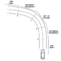
図1は、本実施形態の速度制御の説明に際し、直線区間(曲率0)、緩和曲線区間(曲率単調変化)、曲率一定区間(定常旋回)を持つカーブ路(カーブ区間を含む道路)、およびそこを走行する車両の概念図を示している。 In the description of the speed control of the present embodiment, FIG. 1 illustrates a curve road (a road including a curve section) having a straight section (curvature 0), a relaxation curve section (curvature monotonous change), a constant curvature section (steady turn), and The conceptual diagram of the vehicle which drive | works there is shown.
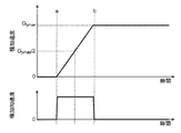
図2は、車両の横加速度制御の一形態として、図1のaからbに至る曲率単調増加となる緩和曲線区間の走行軌道がクロソイド曲線となるよう一定速度で走行した場合の、横加速度、および横加速度の時間変化(横加加速度)を示したものである。つまり、図2は、クロソイド曲線で構成される緩和曲線区間を一定速度で走行する際に車両に発生する典型的な横加速度変化を示している。 FIG. 2 shows an example of the lateral acceleration control of the vehicle, the lateral acceleration when the vehicle travels at a constant speed so that the traveling track of the relaxation curve section that increases monotonically from a to b in FIG. 1 becomes a clothoid curve. The time change of the lateral acceleration (lateral jerk) is also shown. That is, FIG. 2 shows a typical lateral acceleration change that occurs in the vehicle when traveling at a constant speed in a relaxation curve section formed by a clothoid curve.
図1のaからbに至る曲率単調増加区間において、クロソイド曲線となる走行軌道にて定速走行した場合、図2に示すように、横加速度は線形に増加し、定常旋回時の横加速度(最大値)Gymaxに至る。この時、車両に発生する横加加速度は、図2のaからbに至るまでの間、ほぼ一定の値となる。 In the monotonically increasing section of curvature from a to b in FIG. 1, when traveling at a constant speed on a trajectory having a clothoid curve, the lateral acceleration increases linearly as shown in FIG. Maximum value) G ymax . At this time, the lateral jerk generated in the vehicle has a substantially constant value from a to b in FIG.
この場合、図2のb付近、すなわち車両に発生する横加速度が大きい領域まで横加加速度が大きくなり、路面状態等によっては、横加速度変化が大きいことによる不安定挙動が発生する可能性がある。また、車両に発生する加速度が大きい状態での加速度変化は、乗員に不快感を与える可能性がある。 In this case, the lateral jerk increases to the vicinity of b in FIG. 2, that is, the region where the lateral acceleration generated in the vehicle is large, and depending on the road surface condition or the like, there is a possibility that unstable behavior due to a large lateral acceleration change may occur. Moreover, the acceleration change in the state where the acceleration generated in the vehicle is large may give a passenger discomfort.
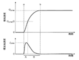
本実施形態では、これらの加速度と加加速度の関係を鑑み、加速度が大きい領域では加加速度を抑制するように、車両に発生する加速度を(自動的に)制御することにより、加速度変化に伴う車両の不安定挙動の発生を抑制し、乗員の快適性を向上する。具体的には、図3に示すように、図1のaからbに至る曲率単調増加となる緩和曲線区間において、車両に発生する横加加速度が横加速度の小さい領域で最大値Jymaxをとり、その後、横加速度の増加と共に、横加加速度が減少するよう、車両に発生する加速度を制御する。ここで、横加速度の小さい領域とは、車両に発生する横加速度が定常旋回時に発生する横加速度(最大値)Gymaxの半分以下の領域(領域A)とし、横加速度の大きい領域とは、車両に発生する横加速度が定常旋回時に発生する横加速度(最大値)Gymaxの半分より大きい領域(領域B)とする。 In the present embodiment, in view of the relationship between these accelerations and jerk, a vehicle that accompanies a change in acceleration is controlled by (automatically) controlling the acceleration generated in the vehicle so as to suppress the jerk in a region where acceleration is large. Suppresses the occurrence of unstable behavior and improves passenger comfort. Specifically, as shown in FIG. 3, in the relaxation curve section where the curvature monotonously increases from a to b in FIG. 1, the lateral jerk generated in the vehicle takes the maximum value J ymax in the region where the lateral acceleration is small, Thereafter, the acceleration generated in the vehicle is controlled so that the lateral jerk decreases as the lateral acceleration increases. Here, the region where the lateral acceleration is small is the region where the lateral acceleration generated in the vehicle is less than half of the lateral acceleration (maximum value) Gymax that occurs during steady turning (region A), and the region where the lateral acceleration is large is A region (region B) in which the lateral acceleration generated in the vehicle is larger than half of the lateral acceleration (maximum value) Gymax generated during steady turning.
以下、緩和曲線区間走行時の走行軌道がクロソイド曲線となる走行をクロソイド曲線走行、本実施形態による走行を非クロソイド曲線走行と呼ぶ。 Hereinafter, the travel in which the travel trajectory during the relaxation curve section travels is a clothoid curve, and the travel according to the present embodiment is referred to as a non-clothoid curve travel.
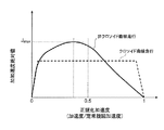
図4Aは、クロソイド曲線走行、非クロソイド曲線走行それぞれの場合の、定常旋回時(定常旋回状態)に車両に発生する加速度(定常旋回加速度)で車両に発生する加速度を正規化した正規化加速度と加加速度絶対値との関係を示したものである。横軸を正規化加速度、縦軸を加加速度絶対値とした場合、クロソイド曲線走行では、正規化加速度の増加に対し、加加速度絶対値がほぼ一定となる。それに対し、非クロソイド曲線走行(本実施形態)では、正規化加速度が0.5よりも小さい領域(図示例では、0.3から0.5までの領域)で加加速度絶対値が最大値Jmaxを取り、その後、正規化加速度の増加とともに減少する傾向となる。 FIG. 4A shows a normalized acceleration obtained by normalizing acceleration generated in the vehicle with acceleration (steady turning acceleration) generated in the vehicle during steady turning (steady turning state) in each of the clothoid curve traveling and the non-clothoid curve traveling. It shows the relationship with the jerk absolute value. When the horizontal axis is normalized acceleration, and the vertical axis is jerk absolute value, the absolute jerk value becomes almost constant with increase in the normalized acceleration in clothoid curve running. On the other hand, in the non-cursoid curve running (this embodiment), the jerk absolute value takes the maximum value J max in the region where the normalized acceleration is smaller than 0.5 (in the illustrated example, the region from 0.3 to 0.5), and then It tends to decrease as the normalized acceleration increases.
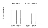
また、図4Bは、クロソイド曲線走行、非クロソイド曲線走行それぞれの場合の、前記領域A、Bそれぞれにおける加加速度の時間平均を示したものである。図4Bに示すように、クロソイド曲線走行では、前記領域Aにおける加加速度時間平均値と前記領域Bにおける加加速度時間平均値とがほぼ同じとなる。それに対し、非クロソイド曲線走行(本実施形態)では、前記領域Aにおける加加速度時間平均値は、前記領域Bにおける加加速度時間平均値よりも大きくなる。 FIG. 4B shows time averages of jerk in each of the regions A and B in the case of clothoid curve running and non-clothoid curve running, respectively. As shown in FIG. 4B, in the clothoid curve running, the jerk time average value in the region A and the jerk time average value in the region B are substantially the same. On the other hand, in the non-clothoid running (this embodiment), the jerk time average value in the region A is larger than the jerk time average value in the region B.
なお、前述の図3や図4Aでは、定速走行での車両横方向に発生する加速度である横加速度(の絶対値)とその横加速度の時間変化である横加加速度(の絶対値)の関係等を示したが、前後加速度を伴う場合であっても、車両横方向に発生する加速度である横加速度(の絶対値)と車両前後方向に発生する加速度である前後加速度(の絶対値)との合成加速度(の絶対値)と、その合成加速度(の絶対値)の時間変化ないし変化率である合成加加速度(の絶対値)との関係が、図3に示した関係となるように前後加速度および横加速度を制御すればよい。また、同様に、合成加速度を定常旋回時の合成加速度にて正規化した正規化合成加速度と合成加速度の時間変化(合成加加速度)の絶対値との関係が、図4Aに示した関係となるように前後加速度および横加速度を制御すればよい。 In FIG. 3 and FIG. 4A described above, the relationship between the lateral acceleration (absolute value) that is an acceleration generated in the lateral direction of the vehicle in constant speed traveling and the lateral jerk (its absolute value) that is a temporal change of the lateral acceleration. However, even if it is accompanied by longitudinal acceleration, lateral acceleration (absolute value) that is the acceleration generated in the vehicle lateral direction and longitudinal acceleration (absolute value) that is the acceleration generated in the vehicle longitudinal direction The relationship between the combined acceleration (the absolute value thereof) and the combined jerk (the absolute value thereof), which is the time change or rate of change of the combined acceleration (the absolute value thereof), becomes the relationship shown in FIG. The acceleration and lateral acceleration may be controlled. Similarly, the relationship between the normalized combined acceleration obtained by normalizing the combined acceleration with the combined acceleration during steady turning and the absolute value of the temporal change (combined jerk) of the combined acceleration is the relationship shown in FIG. 4A. Thus, the longitudinal acceleration and the lateral acceleration may be controlled.
このような加速度(横加速度、もしくは、前後加速度および横加速度)制御を行うことにより、自動走行制御による旋回走行時の加速度変化に伴う車両の不安定挙動の発生を抑制でき、乗員の快適性を向上させることができる。 By performing such acceleration control (lateral acceleration or longitudinal acceleration and lateral acceleration), it is possible to suppress the occurrence of unstable behavior of the vehicle due to acceleration changes during turning by automatic traveling control, and to improve passenger comfort. Can be improved.
[第1実施形態]
以下、図5〜図9を用いて、本発明の第1実施形態による車両運動制御装置の構成及び動作について説明する。
[First Embodiment]
Hereinafter, the configuration and operation of the vehicle motion control apparatus according to the first embodiment of the present invention will be described with reference to FIGS.
最初に、図5、6を用いて、本発明の第1実施形態による車両運動制御装置を搭載した車両および当該車両運動制御装置の構成について説明する。 First, the configuration of the vehicle equipped with the vehicle motion control device according to the first embodiment of the present invention and the vehicle motion control device will be described with reference to FIGS.
図5は、本発明の第1実施形態による車両運動制御装置を搭載した車両の構成図を示したものである。 FIG. 5 shows a configuration diagram of a vehicle equipped with the vehicle motion control apparatus according to the first embodiment of the present invention.
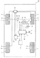
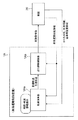
本実施形態の車両運動制御装置1は車両20に搭載されるものであり、車両運動状態情報を取得するセンサ(加速度センサ2、ジャイロセンサ3、車輪速センサ8)、ドライバ操作情報を取得するセンサ(操舵角センサ5、ブレーキペダルセンサ17、アクセルペダルセンサ18)および自車両走行路情報を取得するセンサ(コース形状取得センサ6、自車両位置検出センサ9、外界情報検出センサ19)から得られる各種情報に基づいて、加速度制御に必要な演算を行い、その演算結果に基づいて、車両に発生する前後加速度および/もしくは横加速度を制御可能なアクチュエータ(ブレーキアクチュエータ11、駆動アクチュエータ13、舵角制御アクチュエータ16)の駆動制御を行う各制御ユニット(ブレーキ制御ユニット10、駆動トルク制御ユニット12、舵角制御ユニット15)に通信ライン14を通じて制御指令値を送信する。
The vehicle
ここで、前記車両運動状態情報を取得するセンサとして、車両速度、前後加速度、横加速度、ヨーレイトを取得できるセンサ、もしくは手段であればよく、上記センサ構成に限定するものではない。例えばグローバルポジショニングシステム(GPS)により得られる位置情報を微分することで、車両速度を取得してもよい。また、カメラのような画像取得センサを用いて車両のヨーレイト、前後加速度、横加速度を取得してもよい。また、前記車両運動制御装置1が直接センサの入力を持たなくともよい。例えば別な制御ユニット(例えばブレーキ制御ユニット10)から通信ライン14を通じて必要な情報を取得してもよい。
Here, the sensor that acquires the vehicle motion state information may be any sensor or means that can acquire vehicle speed, longitudinal acceleration, lateral acceleration, and yaw rate, and is not limited to the above sensor configuration. For example, the vehicle speed may be acquired by differentiating position information obtained by the global positioning system (GPS). Further, the yaw rate, longitudinal acceleration, and lateral acceleration of the vehicle may be acquired using an image acquisition sensor such as a camera. Further, the vehicle
ドライバ操作情報を取得するセンサとして、ドライバによるステアリングホイール4の操作量、図示していないブレーキペダルおよびアクセルペダルの操作量を取得できればよく、上述の車両運動状態情報の取得同様、前記車両運動制御装置1が直接センサの入力を持たなくともよい。例えば別な制御ユニット(例えばブレーキ制御ユニット10)から通信ライン14を通じて必要な情報を取得してもよい。
As the sensor for acquiring the driver operation information, it is only necessary to acquire the operation amount of the
自車両走行路情報を取得するセンサとして、グローバルポジショニングシステム(GPS)を自車両位置検出センサ9として用い、外界情報検出センサ19として、カメラやレーダ等、自車両周辺の障害物を検出して走行可能な領域を検出可能なセンサを用い、コース形状取得センサ6として、ナビゲーションシステムのような自車両の走行経路情報を取得できるものを利用できる。ここで、自車両走行路情報を取得するセンサとして、自車両の進行方向におけるコース形状および走行可能領域が取得できる手段であればよく、これらセンサに限定するものではない。例えばデータセンタや路上に設置された道路情報を送信する機器との通信により自車両前方のコース形状を取得する方法であってもよいし、カメラのような撮像手段により自車両前方もしくは周囲、またはその両方の画像を取得し、自車両前方のコース形状を取得する方法であってもよい。また、これら手段のいずれか、もしくはその組み合わせにより、自車両進行方向のコース形状を演算するユニットから通信ライン14を通じて取得する方法であってもよい。
A global positioning system (GPS) is used as the own vehicle position detection sensor 9 as a sensor for acquiring own vehicle travel path information, and an outside
前記車両20に発生する前後加速度を制御可能な加減速アクチュエータ(ブレーキアクチュエータ11、駆動アクチュエータ13)は、タイヤ7と路面間に発生する力を制御することで当該車両20に発生する前後加速度を制御可能なアクチュエータであり、例えば、燃焼状態を制御することでタイヤ7にかかる制駆動トルクを制御し、車両20の前後加速度を制御可能な燃焼エンジン、もしくは電流を制御することでタイヤ7にかかる制駆動トルクを制御し、車両20の前後加速度を制御可能な電動モータ、もしくは動力を各車輪に伝達する際の変速比を変えることで車両20の前後加速度を制御可能な変速機、もしくは各車輪のブレーキパッドにブレーキディスクを押しつけることで車両20に前後加速度を発生させる摩擦ブレーキといった、前後加速度を制御可能な加減速アクチュエータを適用することができる。
An acceleration / deceleration actuator (
また、車両運動制御装置1は、記憶領域、演算処理能力、および信号の入出力手段等を有する演算装置を備えており、前記車両運動状態情報、前記ドライバ操作情報、前記自車両走行路情報により得られた各種情報から車両20に発生させる前後加速度指令値を演算し、前記前後加速度指令値となる前後加速度を発生し得る前記加減速アクチュエータを前後加速度発生手段として、前記加減速アクチュエータ(ブレーキアクチュエータ11、駆動アクチュエータ13)の駆動制御器(ブレーキ制御ユニット10、駆動トルク制御ユニット12)へ前記前後加速度指令値を送る。また、前記車両運動状態情報、前記ドライバ操作情報、前記自車両走行路情報により得られた各種情報から車両20に発生させる横運動指令値を演算し、前記横運動を発生し得る舵角制御アクチュエータ16を旋回運動発生手段として、前記舵角制御アクチュエータ16の駆動制御器(舵角制御ユニット15)へ前記横運動指令値としての舵角指令値を送る(詳細は後述)。
The vehicle
ここで、車両運動制御装置1から送る信号は前後加速度そのものではなく、前記加減速アクチュエータによって前記前後加速度指令値を実現し得る信号であればよい。同様に、車両運動制御装置1から送る信号は舵角そのものではなく、前記舵角制御アクチュエータ16により、舵角指令値を実現し得る信号であればよい。
Here, the signal sent from the vehicle
例えば、前記加減速アクチュエータが燃焼エンジンである場合、前記前後加速度指令値を実現し得る制駆動トルク指令値を駆動トルク制御ユニット12へ送る。また、駆動トルク制御ユニット12を介さず、前後加速度指令値を実現する燃焼エンジンの駆動信号を、燃焼エンジンの制御アクチュエータに直接送ってもよい。また、油圧によりブレーキパッドをブレーキディスクに押し付ける油圧式摩擦ブレーキを用いる場合、前後加速度指令値を実現する油圧指令値をブレーキ制御ユニット10へ送る。また、ブレーキ制御ユニット10を介さず、前後加速度指令値を実現する油圧式摩擦ブレーキ駆動アクチュエータの駆動信号を油圧式摩擦ブレーキ駆動アクチュエータに直接送ってもよい。
For example, when the acceleration / deceleration actuator is a combustion engine, a braking / driving torque command value that can realize the longitudinal acceleration command value is sent to the driving
また、前後加速度指令値を実現する際に、前後加速度指令値に応じて駆動制御を行う前記加減速アクチュエータを変更してもよい。 Further, when the longitudinal acceleration command value is realized, the acceleration / deceleration actuator that performs drive control according to the longitudinal acceleration command value may be changed.
例えば、前記燃焼エンジンと油圧式摩擦ブレーキを前記加減速アクチュエータとして持つ場合、前記前後加速度指令値が前記燃焼エンジンの制駆動トルク制御により実現できる範囲であれば、前記燃焼エンジンを駆動制御し、前記前後加速度指令値が前記燃焼エンジンの制駆動トルク制御で実現できない範囲の負の値である場合、前記燃焼エンジンと合わせて油圧式摩擦ブレーキを駆動制御する。また、前記電動モータと前記燃焼エンジンを前記加減速アクチュエータとして持つ場合、前記前後加速度の時間変化が大きい場合は前記電動モータを駆動制御し、前記前後加速度の時間変化が小さい場合は前記燃焼エンジンを駆動制御するようにしてもよい。また、通常時は前記前後加速度指令値を電動モータにより駆動制御し、バッテリーの状態等により電動モータにより前後加速度指令を実現できない場合、他の加減速アクチュエータ(燃焼エンジン、油圧式摩擦ブレーキ等)を駆動制御するようにしてもよい。 For example, when having the combustion engine and a hydraulic friction brake as the acceleration / deceleration actuator, if the longitudinal acceleration command value is within a range that can be realized by braking / driving torque control of the combustion engine, the combustion engine is driven and controlled, When the longitudinal acceleration command value is a negative value that cannot be realized by the braking / driving torque control of the combustion engine, the hydraulic friction brake is driven and controlled together with the combustion engine. Further, when the electric motor and the combustion engine are used as the acceleration / deceleration actuator, the electric motor is driven and controlled when the time change of the longitudinal acceleration is large, and the combustion engine is controlled when the time change of the longitudinal acceleration is small. You may make it drive-control. Also, when the longitudinal acceleration command value is normally driven and controlled by an electric motor and the longitudinal acceleration command cannot be realized by the electric motor due to the battery condition, etc., other acceleration / deceleration actuators (combustion engine, hydraulic friction brake, etc.) You may make it drive-control.
また、通信ライン14として、信号によって異なる通信ラインおよび通信プロトコルを用いてもよい。例えば大容量のデータをやり取りする必要のある自車両走行路情報を取得するセンサとの通信にイーサネットを用い、各アクチュエータとの通信にはController Area Network(CAN)を用いる構成であってもよい。
Further, as the
図6は、本発明の第1実施形態による車両運動制御装置1の構成図を示したものである。
FIG. 6 shows a configuration diagram of the vehicle
図示するように、車両運動制御装置1は、目標軌道取得部1a、車両運動状態取得部1b、車両運動制御演算部1c、および制御指令送信部1dからなる。
As shown in the drawing, the vehicle
目標軌道取得部1aでは、前記自車両走行路情報、および車両運動状態情報から車両20を走行させるための目標軌道および走行可能領域を取得する。ここで、目標軌道の作成方法としては、自車両が走行するコース形状から目標軌道を作成する方法であってもよいし、データセンタとの通信により、自車両が走行する路面の過去の走行データ軌跡を取得し、その軌跡に基づいて作成する方法であってもよい。
The target
車両運動状態取得部1bでは、前記車両運動状態情報から車両20の運動状態(走行速度、旋回状態、ドライバ操作量等)を取得する。
The vehicle movement
車両運動制御演算部1cでは、前記目標軌道取得部1aおよび車両運動状態取得部1bにより得られた情報に基づいて、前記速度制御による前後加速度指令値、もしくは前記速度制御による前後加速度指令値と前記舵角制御による舵角指令値の両方を演算し、その演算結果を制御指令送信部1dに送る。
In the vehicle motion control calculation unit 1c, based on the information obtained by the target
制御指令送信部1dでは、前記車両運動制御演算部1cにより作成された前後加速度指令値、もしくは前後加速度指令値と舵角指令値の両方に基づいて、前記前後加速度および/もしくはタイヤ実舵角を制御可能なアクチュエータ(ブレーキアクチュエータ11、駆動アクチュエータ13、舵角制御アクチュエータ16)の駆動制御を行う各制御ユニット(ブレーキ制御ユニット10、駆動トルク制御ユニット12、舵角制御ユニット15)に制御指令値を送る。
In the control command transmission unit 1d, based on the longitudinal acceleration command value created by the vehicle motion control calculation unit 1c or both the longitudinal acceleration command value and the steering angle command value, the longitudinal acceleration and / or the actual tire steering angle are calculated. A control command value is sent to each control unit (
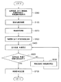
図7は、第1実施形態の前記車両運動制御装置1における制御フローチャートを示したものである。
FIG. 7 shows a control flowchart in the vehicle
S000では、上述のように目標軌道、走行可能範囲、車速制御範囲、車両運動状態を取得する。ここで、目標軌道は、図8に示すように、車両重心位置を原点とし、車両速度ベクトルの方向を正としたXv軸、それと直行するYv軸を取った座標上のノード点位置データNPn(Xvn,Yvn)として変換される。nは、最も車両に近い点を0とし、自車両進行方向に向かって1、2・・・、nmaxと増加する整数である。また、nmaxは取得可能なノード点位置データ番号nの最大値である。また、NP0のYv軸成分であるYv0は、車両の横方向偏差となる。また、各ノード点はノード点位置における走行可能範囲、および車速制御範囲といった情報も合わせて持つものとする。 In S000, the target track, the travelable range, the vehicle speed control range, and the vehicle motion state are acquired as described above. Here, as shown in FIG. 8, the target trajectory is the node point position data NP n on the coordinates taking the Xv axis with the vehicle center of gravity position as the origin and the direction of the vehicle speed vector as positive, and the Yv axis orthogonal thereto. Converted as (Xv n , Yv n ). n is an integer which increases to 1, 2..., nmax in the traveling direction of the host vehicle, with 0 being the closest point to the vehicle. Nmax is the maximum value of node point position data number n that can be acquired. Further, Yv 0 that is the Yv axis component of NP 0 is the lateral deviation of the vehicle. Each node point also has information such as a travelable range at the node point position and a vehicle speed control range.
S100では、目標軌道、車速制御範囲、車両運動状態から前後加速度を演算する。例えば車両速度が車速制御範囲を超えて高い場合、車速制御範囲に収まるよう負の前後加速度指令値を演算する。また、目標軌道がカーブ路形状(走行路の道路曲率絶対値が増加して最大値もしくは略一定に至る形状)となっており、カーブ路に応じた加減速制御をおこなう場合、カーブ路形状に基づいた前後加速度指令値が演算される。 In S100, the longitudinal acceleration is calculated from the target track, the vehicle speed control range, and the vehicle motion state. For example, when the vehicle speed is higher than the vehicle speed control range, a negative longitudinal acceleration command value is calculated so as to be within the vehicle speed control range. In addition, the target track has a curved road shape (a shape in which the absolute value of the road curvature of the traveling road increases and reaches a maximum value or a substantially constant value). When performing acceleration / deceleration control according to a curved road, Based on the longitudinal acceleration command value is calculated.
S200では、目標軌道、車両運動状態から横加速度を演算する。ここで、目標軌道がカーブ路形状(走行路の道路曲率絶対値が増加して最大値もしくは略一定に至る形状)となっており、カーブ路に応じた横加速度制御をおこなう場合、車両20に発生する横加速度と横加加速度の関係が、上述の図3ないし図4Aに示した関係となるよう横加速度を演算する。
In S200, the lateral acceleration is calculated from the target trajectory and the vehicle motion state. Here, the target track has a curved road shape (a shape in which the absolute value of the road curvature of the traveling road increases and reaches a maximum value or a substantially constant value), and when the lateral acceleration control corresponding to the curved road is performed, the
例えば、図9に示すように、旋回走行開始時刻t0から横加加速度が最大となる時刻t1までの間の横加速度をGy1とし、時刻t1から定常旋回状態の横加速度Gymaxとなる時刻t2までの間の横加速度をGy2とすると、Gy1、Gy2は二つのチューニング変数ω、kおよび時刻tを用いて、以下の式(1)、(2)で与える。
![]()
![]()
![]()
![]()
図7に戻り、S300では、横運動に基づいた前後加速度を演算する。この横運動に基づいた前後加速度の演算方法としては、例えば上記特許文献3に示す横加加速度に基づいた前後加速度制御が挙げられる。 Returning to FIG. 7, in S300, the longitudinal acceleration based on the lateral motion is calculated. As a method for calculating the longitudinal acceleration based on the lateral motion, for example, longitudinal acceleration control based on the lateral jerk shown in Patent Document 3 can be cited.
S400では、車両運動状態、演算された横加速度、前後加速度に基づいて、車両20の走行軌道、車速の推定を行う。
In S400, the traveling track and the vehicle speed of the
S500では、推定された走行軌道、車速が制御可能範囲内か否かを判定する。ここで、制御範囲外と判定された場合、S600に進み、制御範囲内と判定された場合、S700へと進む。 In S500, it is determined whether or not the estimated traveling track and vehicle speed are within the controllable range. Here, if it is determined that it is outside the control range, the process proceeds to S600, and if it is determined that it is within the control range, the process proceeds to S700.
S600では、前後加速度、横加速度の補正を行う。例えば、横加速度の補正においては、数(1)、(2)に示したチューニング変数ω、kを変更することで、S400にて走行軌道を変化させる。また、上記特許文献3に示す横加加速度に基づいた前後加速度制御の制御ゲインを変更することで、S400にて走行軌道および車速を変化させる。その後、再び、S500にて、走行軌道、車速が制御可能範囲内か否かを判定する。 In S600, longitudinal acceleration and lateral acceleration are corrected. For example, in the correction of the lateral acceleration, the running track is changed in S400 by changing the tuning variables ω and k shown in the equations (1) and (2). Further, by changing the control gain of the longitudinal acceleration control based on the lateral jerk shown in Patent Document 3, the traveling track and the vehicle speed are changed in S400. Thereafter, in S500 again, it is determined whether or not the traveling track and the vehicle speed are within the controllable range.
S700では、前記前後加速度指令値、横加速度指令値に基づいて、各アクチュエータの制御指令値を演算して送信する。例えば、燃焼エンジンを用いて前後加速度を制御し、電動パワーステアリングを用いてヨーモーメント(横加速度)を制御する場合、前記前後加速度を車両に発生させる制駆動トルク指令値を燃焼エンジンの制御コントローラに送り、前記横加速度を車両に発生させる舵角指令値を電動パワーステアリングの制御コントローラに送る。 In S700, the control command value of each actuator is calculated and transmitted based on the longitudinal acceleration command value and the lateral acceleration command value. For example, when the longitudinal acceleration is controlled using a combustion engine and the yaw moment (lateral acceleration) is controlled using an electric power steering, a braking / driving torque command value for causing the vehicle to generate the longitudinal acceleration is supplied to the combustion engine controller. The steering angle command value for causing the vehicle to generate the lateral acceleration is sent to the control controller of the electric power steering.
以上のように、本第1実施形態では、直線区間を走行してきた車両20が定常旋回状態に至るまでの間に発生する加加速度が発生する横加速度が小さい領域(車両20に発生する横加速度が定常旋回時に発生する横加速度Gymaxの半分以下の領域A)で最大とし、発生する加速度が大きい状態(車両20に発生する横加速度が定常旋回時に発生する横加速度Gymaxの半分より大きい領域B)での加速度変化を抑制することで、自動走行制御による旋回走行時の加速度変化に伴う車両20の不安定挙動の発生を抑制でき、乗員の快適性を向上する効果も期待できる。
As described above, in the first embodiment, the lateral acceleration in which the jerk generated until the
[第2実施形態]
次に、図10〜図11を用いて、本発明の第2実施形態による車両運動制御装置(目標軌道生成装置)の構成及び動作について説明する。
[Second Embodiment]
Next, the configuration and operation of the vehicle motion control device (target trajectory generation device) according to the second embodiment of the present invention will be described with reference to FIGS.
図10は、本発明の第2実施形態による車両運動制御装置(目標軌道生成装置)1Aの構成図を示したものである。なお、図10に示す例では、車両運動制御装置(目標軌道生成装置)1Aは車両20の外部に備えられているが、上記第1実施形態と同様、車両20内に配備してもよい。
FIG. 10 shows a configuration diagram of a vehicle motion control device (target trajectory generation device) 1A according to the second embodiment of the present invention. In the example shown in FIG. 10, the vehicle motion control device (target trajectory generation device) 1 </ b> A is provided outside the
本実施形態では、車両運動制御装置1Aは、記憶領域、演算処理能力、および信号の入出力手段等を有する複数の演算装置を備えており、主に、軌道演算部1Aa、および走行制御演算部1Abを備える。 In the present embodiment, the vehicle motion control device 1A includes a plurality of calculation devices having a storage area, calculation processing capability, signal input / output means, and the like, and mainly includes a track calculation unit 1Aa and a travel control calculation unit. 1Ab.
軌道演算部1Aaでは、前記コース形状、前記外界情報、前記自車両位置情報、および前記車両運動状態情報から、車両20の目標軌道および目標車速を作成する。
The trajectory calculation unit 1Aa creates a target trajectory and a target vehicle speed of the
走行制御演算部1Abでは、前記目標軌道、目標車速および前記車両運動状態情報から、車両20に発生させる横運動指令値、もしくは横運動指令値と前後加速度指令値の両方を演算し、前記前後加速度指令値となる前後加速度を発生し得る前記加減速アクチュエータを前後加速度発生手段として、前記加減速アクチュエータ(ブレーキアクチュエータ11、駆動アクチュエータ13)の駆動制御器(ブレーキ制御ユニット10、駆動トルク制御ユニット12)へ前記前後加速度指令値を送り、車両20に発生させる前記横運動指令値を発生し得る舵角制御アクチュエータ16を旋回運動発生手段として、前記舵角制御アクチュエータ16の駆動制御器(舵角制御ユニット15)へ前記横運動指令値としての舵角指令値を送る。
The travel control calculation unit 1Ab calculates a lateral motion command value to be generated by the
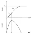
詳しくは、前記軌道演算部1Aaは、前記コース形状、前記外界情報、前記自車両位置情報、および前記車両運動状態情報から目標軌道および目標車速を作成する際、旋回走行時に車両20に発生する加速度と加加速度の関係が上述の図3ないし図4Aに示す形となるよう、目標軌道および目標車速を作成する。例えば、直線路からカーブ路に進入し、定常旋回状態に至る際の目標軌道の曲率(軌道曲率)を上に凸の曲線とする。目標車速が略一定であれば、目標軌道の曲率の時間変化と曲率の関係が、図11に示すように、定常旋回時(定常旋回状態)の曲率(最大値)κmaxの半分κmax/2となる時刻t3よりも、曲率の時間変化が最大となる時刻t1が早くなるよう、目標軌道を生成する。すなわち、前記軌道演算部1Aaは、目標軌道の曲率が略直線状態から最大値もしくは一定となるまでの遷移区間において、前記目標軌道上を略一定速で移動する車両20における曲率と曲率の時間変化において、図11に示すように、前記目標軌道の曲率の最大値κmaxの半分κmax/2以下の領域(領域C)において、前記曲率の時間変化が最大となるよう、目標軌道を生成する。ここで生成される目標軌道は、前記目標軌道の曲率が最大値κmaxの半分κmax/2以下の領域(領域C)における曲率時間変化の時間平均値が、前記曲率の最大値κmaxの半分κmax/2より大きい領域(領域D)における曲率時間変化の時間平均値よりも大きくなる目標軌道となる。
Specifically, the trajectory calculation unit 1Aa generates an acceleration generated in the
前記走行制御演算部1Abは、前記したように、軌道演算部1Aaで作成された目標軌道および目標車速を実現するために、車両20に発生させる横運動指令値、もしくは横運動指令値と前後加速度指令値の両方を演算し、前記前後加速度指令値となる前後加速度を発生し得る前記加減速アクチュエータを前後加速度発生手段として、前記加減速アクチュエータ(ブレーキアクチュエータ11、駆動アクチュエータ13)の駆動制御器(ブレーキ制御ユニット10、駆動トルク制御ユニット12)へ前記前後加速度指令値を送り、車両20に発生させる前記横運動指令値を発生し得る舵角制御アクチュエータ16を旋回運動発生手段として、前記舵角制御アクチュエータ16の駆動制御器(舵角制御ユニット15)へ前記横運動指令値としての舵角指令値を送る。
As described above, the travel control calculation unit 1Ab generates a lateral motion command value generated by the
以上のように、本第2実施形態では、車両運動制御装置(目標軌道生成装置)1Aにて目標軌道を生成する際に、目標軌道の曲率と曲率の時間変化の関係を前記した図11に示すような制約を与えることで、走行可能範囲内を走行可能かつ車両20に発生する加速度と加加速度の関係が図3ないし図4Aに示すようになる目標軌道および目標車速が軌道演算部1Aa側で演算できる。そのため、上記第1実施形態と同様の効果が得られるとともに、走行制御演算部1Ab側の演算負荷を低減でき、また、軌道演算装置(軌道演算部1Aa)を他の走行制御演算装置(走行制御演算部1Ab)と組み合わせた制御も実現できる。
As described above, in the second embodiment, when the target trajectory is generated by the vehicle motion control device (target trajectory generating device) 1A, the relationship between the curvature of the target trajectory and the time variation of the curvature is shown in FIG. By giving the constraints as shown, the target trajectory and the target vehicle speed at which the relationship between the acceleration and jerk that can travel within the travelable range and are generated in the
なお、本発明は上記した実施形態に限定されるものではなく、様々な変形形態が含まれる。例えば、上記した実施形態は本発明を分かりやすく説明するために詳細に説明したものであり、必ずしも説明した全ての構成を備えるものに限定されるものではない。また、ある実施形態の構成の一部を他の実施形態の構成に置き換えることが可能であり、また、ある実施形態の構成に他の実施形態の構成を加えることも可能である。また、各実施形態の構成の一部について、他の構成の追加・削除・置換をすることが可能である。 In addition, this invention is not limited to above-described embodiment, Various deformation | transformation forms are included. For example, the above-described embodiment has been described in detail for easy understanding of the present invention, and is not necessarily limited to one having all the configurations described. Further, a part of the configuration of an embodiment can be replaced with the configuration of another embodiment, and the configuration of another embodiment can be added to the configuration of an embodiment. Moreover, it is possible to add / delete / replace other configurations for a part of the configurations of the embodiments.
また、上記の各構成、機能、処理部、処理手段等は、それらの一部又は全部を、例えば集積回路で設計する等によりハードウェアで実現してもよい。また、上記の各構成、機能等は、プロセッサがそれぞれの機能を実現するプログラムを解釈し、実行することによりソフトウェアで実現してもよい。各機能を実現するプログラム、テーブル、ファイル等の情報は、メモリや、ハードディスク、SSD(Solid State Drive)等の記憶装置、または、ICカード、SDカード、DVD等の記録媒体に置くことができる。 Each of the above-described configurations, functions, processing units, processing means, and the like may be realized by hardware by designing a part or all of them with, for example, an integrated circuit. Each of the above-described configurations, functions, and the like may be realized by software by interpreting and executing a program that realizes each function by the processor. Information such as programs, tables, and files that realize each function can be stored in a storage device such as a memory, a hard disk, or an SSD (Solid State Drive), or a recording medium such as an IC card, an SD card, or a DVD.
また、制御線や情報線は説明上必要と考えられるものを示しており、製品上必ずしも全ての制御線や情報線を示しているとは限らない。実際には殆ど全ての構成が相互に接続されていると考えてもよい。 Further, the control lines and information lines indicate what is considered necessary for the explanation, and not all the control lines and information lines on the product are necessarily shown. Actually, it may be considered that almost all the components are connected to each other.
1 : 車両運動制御装置(第1実施形態)
1A: 車両運動制御装置(目標軌道生成装置)(第2実施形態)
1a: 目標軌道取得部
1b: 車両運動状態取得部
1c: 車両運動制御演算部
1d: 制御指令送信部
2 : 加速度センサ
3 : ジャイロセンサ
4 : ステアリングホイール
5 : 操舵角センサ
6 : コース形状取得センサ
7 : タイヤ
8 : 車輪速センサ
9 : 自車両位置検出センサ
10 : ブレーキ制御ユニット
11 : ブレーキアクチュエータ
12 : 駆動トルク制御ユニット
13 : 駆動アクチュエータ
14 : 通信ライン
15 : 舵角制御ユニット
16 : 舵角制御アクチュエータ
17 : ブレーキペダルセンサ
18 : アクセルペダルセンサ
19 : 外界情報検出センサ
20 : 車両
1: Vehicle motion control device (first embodiment)
1A: Vehicle motion control device (target trajectory generation device) (second embodiment)
DESCRIPTION OF
Claims (10)
走行路の道路曲率絶対値が増加して最大値もしくは一定に至る旋回走行をする際、
前記車両に発生する加速度について、前記旋回走行時の横加速度が最大となる状態を定常旋回状態とし、前記定常旋回状態時の横加速度の半分以下の領域を第1領域、前記定常旋回状態時の横加速度の半分より大きい領域を第2領域としたとき、前記第1領域において、前記車両に発生する加速度の時間変化である加加速度が最大となり、かつ、前記第1領域における加加速度時間平均値が、前記第2領域における加加速度時間平均値よりも大きくなるよう、前記車両に発生する加速度を制御することを特徴とする車両運動制御装置。 In a vehicle that can automatically control the lateral acceleration generated in the vehicle,
When the road curvature absolute value of the travel path increases and turns to the maximum value or constant,
Regarding the acceleration generated in the vehicle, a state in which the lateral acceleration during turning is maximized is defined as a steady turning state, a region that is less than half of the lateral acceleration in the steady turning state is a first region, and the state in the steady turning state is When a region larger than half of the lateral acceleration is defined as the second region, the jerk that is the time change of the acceleration generated in the vehicle is maximized in the first region, and the jerk time average value in the first region is However, the vehicle motion control device controls the acceleration generated in the vehicle so as to be larger than the average jerk time in the second region.
前記車両に発生する加加速度は、前記横加速度の時間変化である横加加速度の絶対値であることを特徴とする請求項1に記載の車両運動制御装置。 The acceleration generated in the vehicle is an absolute value of a lateral acceleration that is an acceleration in a vehicle lateral direction,
2. The vehicle motion control device according to claim 1, wherein the jerk generated in the vehicle is an absolute value of a lateral jerk that is a temporal change of the lateral acceleration.
前記車両に発生する加加速度は、前記合成加速度の絶対値の時間変化であることを特徴とする請求項1に記載の車両運動制御装置。 The acceleration generated in the vehicle is the absolute value of the combined acceleration of the absolute value of the lateral acceleration that is the acceleration in the vehicle lateral direction and the absolute value of the longitudinal acceleration that is the acceleration in the vehicle longitudinal direction,
The vehicle motion control apparatus according to claim 1, wherein the jerk generated in the vehicle is a time change of an absolute value of the combined acceleration.
前記旋回走行の旋回開始から前記加速度の時間変化が最大となる期間よりも、前記加速度の時間変化が最大値から減少して定常旋回状態に至るまでの期間の方が長くなるよう、前記車両に発生する加速度を制御することを特徴とする請求項1に記載の車両運動制御装置。 When the road curvature absolute value of the travel path increases and turns to the maximum value or constant,
The vehicle has a longer period of time until the time change of the acceleration decreases from the maximum value to reach a steady turning state than a period of time when the time change of the acceleration becomes maximum after the start of turning of the turning travel. The vehicle motion control device according to claim 1, wherein the generated acceleration is controlled.
走行路の道路曲率絶対値が増加して最大値もしくは一定に至る旋回走行をする際、
前記車両に発生する加速度について、前記旋回走行時の横加速度が最大となる状態を定常旋回状態とし、前記定常旋回状態時の横加速度の半分以下の領域を第1領域、前記定常旋回状態時の横加速度の半分より大きい領域を第2領域としたとき、前記第1領域において、前記車両に発生する加速度の時間変化である加加速度が最大となり、かつ、前記第1領域における加加速度時間平均値が、前記第2領域における加加速度時間平均値よりも大きくなる目標軌道を生成することを特徴とする目標軌道生成装置。 In a vehicle that can automatically control the lateral acceleration generated in the vehicle,
When the road curvature absolute value of the travel path increases and turns to the maximum value or constant,
Regarding the acceleration generated in the vehicle, a state in which the lateral acceleration during turning is maximized is defined as a steady turning state, a region that is less than half of the lateral acceleration in the steady turning state is a first region, and the state in the steady turning state is When a region larger than half of the lateral acceleration is defined as the second region, the jerk that is the time change of the acceleration generated in the vehicle is maximized in the first region, and the jerk time average value in the first region is Generating a target trajectory that is larger than the average jerk time in the second region.
前記目標軌道の軌道曲率が直線状態から最大値となるまでの遷移区間において、
前記目標軌道上を一定速で移動する車両における曲率と曲率の時間変化において、
前記曲率の最大値の半分以下の領域を第3領域、前記曲率の最大値の半分より大きい領域を第4領域としたとき、前記第3領域において、前記曲率の時間変化が最大となり、かつ、前記第3領域における曲率時間変化の時間平均値が、前記第4領域における曲率時間変化の時間平均値よりも大きくなる目標軌道を生成することを特徴とする請求項7に記載の目標軌道生成装置。 About the target trajectory,
In the transition section until the trajectory curvature of the target trajectory reaches the maximum value from the straight line state,
In the time variation of curvature and curvature in a vehicle moving at a constant speed on the target track,
When the region less than half of the maximum value of curvature is the third region, and the region greater than half of the maximum value of curvature is the fourth region, in the third region, the time change of the curvature is maximum, and 8. The target trajectory generating apparatus according to claim 7, wherein a target trajectory is generated in which a time average value of curvature time change in the third region is larger than a time average value of curvature time change in the fourth region. .
走行路の道路曲率絶対値が増加して最大値もしくは一定に至る旋回走行をする際、
前記車両に発生する加速度について、前記旋回走行時の横加速度が最大となる状態を定常旋回状態とし、前記定常旋回状態時の横加速度の半分以下の領域を第1領域、前記定常旋回状態時の横加速度の半分より大きい領域を第2領域としたとき、前記第1領域において、前記車両に発生する加速度の時間変化である加加速度が最大となり、かつ、前記第1領域における加加速度時間平均値が、前記第2領域における加加速度時間平均値よりも大きくなるよう、前記車両に発生する加速度を制御することを特徴とする車両運動制御方法。 In a vehicle that can automatically control the lateral acceleration generated in the vehicle,
When the road curvature absolute value of the travel path increases and turns to the maximum value or constant,
Regarding the acceleration generated in the vehicle, a state in which the lateral acceleration during turning is maximized is defined as a steady turning state, a region that is less than half of the lateral acceleration in the steady turning state is a first region, and the state in the steady turning state is When a region larger than half of the lateral acceleration is defined as the second region, the jerk that is the time change of the acceleration generated in the vehicle is maximized in the first region, and the jerk time average value in the first region is The vehicle motion control method is characterized in that the acceleration generated in the vehicle is controlled so as to be larger than the jerk time average value in the second region.
走行路の道路曲率絶対値が増加して最大値もしくは一定に至る旋回走行をする際、
前記車両に発生する加速度について、前記旋回走行時の横加速度が最大となる状態を定常旋回状態とし、前記定常旋回状態時の横加速度の半分以下の領域を第1領域、前記定常旋回状態時の横加速度の半分より大きい領域を第2領域としたとき、前記第1領域において、前記車両に発生する加速度の時間変化である加加速度が最大となり、かつ、前記第1領域における加加速度時間平均値が、前記第2領域における加加速度時間平均値よりも大きくなる目標軌道を生成することを特徴とする目標軌道生成方法。 In a vehicle that can automatically control the lateral acceleration generated in the vehicle,
When the road curvature absolute value of the travel path increases and turns to the maximum value or constant,
Regarding the acceleration generated in the vehicle, a state in which the lateral acceleration during turning is maximized is defined as a steady turning state, a region that is less than half of the lateral acceleration in the steady turning state is a first region, and the state in the steady turning state is When a region larger than half of the lateral acceleration is defined as the second region, the jerk that is the time change of the acceleration generated in the vehicle is maximized in the first region, and the jerk time average value in the first region is Generating a target trajectory that is larger than the average jerk time in the second region.
Priority Applications (5)
| Application Number | Priority Date | Filing Date | Title |
|---|---|---|---|
| JP2017155858A JP6814710B2 (en) | 2017-08-10 | 2017-08-10 | Vehicle motion control device and its method, and target trajectory generator and its method |
| CN201880042722.XA CN110799399B (en) | 2017-08-10 | 2018-07-26 | Vehicle motion control device and method, and target trajectory generation device and method |
| PCT/JP2018/028028 WO2019031255A1 (en) | 2017-08-10 | 2018-07-26 | Device and method for controlling vehicle movement, and device and method for generating target course |
| US16/631,708 US11383698B2 (en) | 2017-08-10 | 2018-07-26 | Device and method for controlling vehicle movement, and device and method for generating target course |
| DE112018003166.7T DE112018003166T5 (en) | 2017-08-10 | 2018-07-26 | DEVICE AND METHOD FOR CONTROLLING A VEHICLE MOVEMENT AND DEVICE AND METHOD FOR GENERATING A TARGET COURSE |
Applications Claiming Priority (1)
| Application Number | Priority Date | Filing Date | Title |
|---|---|---|---|
| JP2017155858A JP6814710B2 (en) | 2017-08-10 | 2017-08-10 | Vehicle motion control device and its method, and target trajectory generator and its method |
Publications (2)
| Publication Number | Publication Date |
|---|---|
| JP2019034591A true JP2019034591A (en) | 2019-03-07 |
| JP6814710B2 JP6814710B2 (en) | 2021-01-20 |
Family
ID=65272305
Family Applications (1)
| Application Number | Title | Priority Date | Filing Date |
|---|---|---|---|
| JP2017155858A Active JP6814710B2 (en) | 2017-08-10 | 2017-08-10 | Vehicle motion control device and its method, and target trajectory generator and its method |
Country Status (5)
| Country | Link |
|---|---|
| US (1) | US11383698B2 (en) |
| JP (1) | JP6814710B2 (en) |
| CN (1) | CN110799399B (en) |
| DE (1) | DE112018003166T5 (en) |
| WO (1) | WO2019031255A1 (en) |
Cited By (2)
| Publication number | Priority date | Publication date | Assignee | Title |
|---|---|---|---|---|
| WO2021153622A1 (en) * | 2020-01-30 | 2021-08-05 | 日立Astemo株式会社 | Vehicle control device, vehicle control method, and vehicle control system |
| WO2022038738A1 (en) * | 2020-08-20 | 2022-02-24 | 日産自動車株式会社 | Driving assistance method and driving assistance device |
Families Citing this family (9)
| Publication number | Priority date | Publication date | Assignee | Title |
|---|---|---|---|---|
| US20210318688A1 (en) * | 2018-09-05 | 2021-10-14 | Nec Corporation | Motion control apparatus, motion control method, nontransitory computer readable medium, and motion control system |
| CN111267853B (en) * | 2018-12-03 | 2021-06-18 | 广州汽车集团股份有限公司 | Adaptive vehicle curve auxiliary control method and device, computer equipment and storage medium |
| US11618439B2 (en) * | 2019-04-11 | 2023-04-04 | Phantom Auto Inc. | Automatic imposition of vehicle speed restrictions depending on road situation analysis |
| JP7263946B2 (en) * | 2019-07-03 | 2023-04-25 | トヨタ自動車株式会社 | vehicle |
| KR20210020608A (en) * | 2019-08-16 | 2021-02-24 | 현대자동차주식회사 | Apparatus for generating an acceleration profile and method for autonomous driving a curved road using the same |
| CN111674403B (en) * | 2020-05-12 | 2021-12-07 | 坤泰车辆系统(常州)有限公司 | Control method for passing in and out of curve by lane centering auxiliary function of automatic driving system |
| CN116438104A (en) * | 2020-09-28 | 2023-07-14 | 日产自动车株式会社 | Vehicle motion control method and vehicle motion control device |
| EP4349674A1 (en) * | 2021-05-28 | 2024-04-10 | Nissan Motor Co., Ltd. | Driving control method and driving control device |
| CN113460055B (en) * | 2021-06-11 | 2022-05-31 | 吉林大学 | Online vehicle driving control area division and area boundary estimation method |
Citations (6)
| Publication number | Priority date | Publication date | Assignee | Title |
|---|---|---|---|---|
| JP2007290650A (en) * | 2006-04-27 | 2007-11-08 | Hitachi Ltd | Motion controller of vehicle |
| WO2012042935A1 (en) * | 2010-09-29 | 2012-04-05 | トヨタ自動車株式会社 | Control device for vehicle |
| JP2015067271A (en) * | 2013-09-30 | 2015-04-13 | 株式会社日立製作所 | Vehicle driving assistance method and vehicle driving assistance device |
| JP2015193329A (en) * | 2014-03-31 | 2015-11-05 | 日立オートモティブシステムズ株式会社 | Vehicle motion control system, vehicle and program |
| JP2017001520A (en) * | 2015-06-10 | 2017-01-05 | マツダ株式会社 | Driving support device |
| JP2017081482A (en) * | 2015-10-30 | 2017-05-18 | 日立オートモティブシステムズ株式会社 | Vehicle motion control device and method thereof |
Family Cites Families (10)
| Publication number | Priority date | Publication date | Assignee | Title |
|---|---|---|---|---|
| JP3803100B2 (en) | 2004-01-13 | 2006-08-02 | 東海旅客鉄道株式会社 | Curve section structure of road |
| JP4568302B2 (en) | 2007-05-18 | 2010-10-27 | 株式会社日立製作所 | Vehicle longitudinal acceleration control apparatus using jerk information |
| JP4967806B2 (en) * | 2007-05-22 | 2012-07-04 | 株式会社日立製作所 | Vehicle speed control device according to path curvature |
| JP4602444B2 (en) * | 2008-09-03 | 2010-12-22 | 株式会社日立製作所 | Driver driving skill support apparatus and driver driving skill support method |
| JP5143103B2 (en) * | 2009-09-30 | 2013-02-13 | 日立オートモティブシステムズ株式会社 | Vehicle motion control device |
| DE102009047476A1 (en) | 2009-12-04 | 2011-06-09 | Robert Bosch Gmbh | Method and control unit for determining a section trajectory of a curve section of a roadway |
| WO2012043683A1 (en) * | 2010-09-28 | 2012-04-05 | 日立オートモティブシステムズ株式会社 | Vehicle motion control device |
| WO2012153367A1 (en) * | 2011-05-11 | 2012-11-15 | 日立オートモティブシステムズ株式会社 | Vehicle operation control device and vehicle operation control system |
| JP5970322B2 (en) * | 2012-10-01 | 2016-08-17 | 日立オートモティブシステムズ株式会社 | Vehicle motion control device |
| EP2853457B1 (en) * | 2013-09-30 | 2019-11-27 | Hitachi, Ltd. | Method and apparatus for performing driving assistance |
-
2017
- 2017-08-10 JP JP2017155858A patent/JP6814710B2/en active Active
-
2018
- 2018-07-26 DE DE112018003166.7T patent/DE112018003166T5/en active Pending
- 2018-07-26 WO PCT/JP2018/028028 patent/WO2019031255A1/en active Application Filing
- 2018-07-26 US US16/631,708 patent/US11383698B2/en active Active
- 2018-07-26 CN CN201880042722.XA patent/CN110799399B/en active Active
Patent Citations (6)
| Publication number | Priority date | Publication date | Assignee | Title |
|---|---|---|---|---|
| JP2007290650A (en) * | 2006-04-27 | 2007-11-08 | Hitachi Ltd | Motion controller of vehicle |
| WO2012042935A1 (en) * | 2010-09-29 | 2012-04-05 | トヨタ自動車株式会社 | Control device for vehicle |
| JP2015067271A (en) * | 2013-09-30 | 2015-04-13 | 株式会社日立製作所 | Vehicle driving assistance method and vehicle driving assistance device |
| JP2015193329A (en) * | 2014-03-31 | 2015-11-05 | 日立オートモティブシステムズ株式会社 | Vehicle motion control system, vehicle and program |
| JP2017001520A (en) * | 2015-06-10 | 2017-01-05 | マツダ株式会社 | Driving support device |
| JP2017081482A (en) * | 2015-10-30 | 2017-05-18 | 日立オートモティブシステムズ株式会社 | Vehicle motion control device and method thereof |
Cited By (4)
| Publication number | Priority date | Publication date | Assignee | Title |
|---|---|---|---|---|
| WO2021153622A1 (en) * | 2020-01-30 | 2021-08-05 | 日立Astemo株式会社 | Vehicle control device, vehicle control method, and vehicle control system |
| JP7408695B2 (en) | 2020-01-30 | 2024-01-05 | 日立Astemo株式会社 | Vehicle control device, vehicle control method, and vehicle control system |
| WO2022038738A1 (en) * | 2020-08-20 | 2022-02-24 | 日産自動車株式会社 | Driving assistance method and driving assistance device |
| JP7485051B2 (en) | 2020-08-20 | 2024-05-16 | 日産自動車株式会社 | Driving assistance method and driving assistance device |
Also Published As
| Publication number | Publication date |
|---|---|
| DE112018003166T5 (en) | 2020-04-02 |
| US20200164870A1 (en) | 2020-05-28 |
| CN110799399B (en) | 2022-11-01 |
| WO2019031255A1 (en) | 2019-02-14 |
| JP6814710B2 (en) | 2021-01-20 |
| CN110799399A (en) | 2020-02-14 |
| US11383698B2 (en) | 2022-07-12 |
Similar Documents
| Publication | Publication Date | Title |
|---|---|---|
| JP6814710B2 (en) | Vehicle motion control device and its method, and target trajectory generator and its method | |
| CN108137039B (en) | Vehicle motion control apparatus and method thereof | |
| US11092967B2 (en) | Vehicle movement control device | |
| US11731631B2 (en) | Vehicle movement control device, method, program, and system, and target trajectory generating device, method, program, and system | |
| JP6764312B2 (en) | Vehicle motion control device, vehicle motion control method, vehicle motion control program | |
| JP7000765B2 (en) | Vehicle driving control device | |
| WO2023139867A1 (en) | Vehicle movement control device and vehicle movement control method | |
| JP6752875B2 (en) | Travel control device | |
| JP5012925B2 (en) | Vehicle motion control device | |
| JP6907896B2 (en) | Autonomous driving system | |
| JP6986463B2 (en) | Driving support device, driving support method and driving support system | |
| WO2020129633A1 (en) | Vehicle operation control device and vehicle operation control method | |
| JP6374308B2 (en) | Vehicle control apparatus and vehicle control method | |
| JP2023108756A (en) | Vehicle integrated control device and vehicle integrated control method |
Legal Events
| Date | Code | Title | Description |
|---|---|---|---|
| A621 | Written request for application examination |
Free format text: JAPANESE INTERMEDIATE CODE: A621 Effective date: 20200311 |
|
| A131 | Notification of reasons for refusal |
Free format text: JAPANESE INTERMEDIATE CODE: A131 Effective date: 20200602 |
|
| A521 | Request for written amendment filed |
Free format text: JAPANESE INTERMEDIATE CODE: A523 Effective date: 20200721 |
|
| TRDD | Decision of grant or rejection written | ||
| A01 | Written decision to grant a patent or to grant a registration (utility model) |
Free format text: JAPANESE INTERMEDIATE CODE: A01 Effective date: 20201208 |
|
| A61 | First payment of annual fees (during grant procedure) |
Free format text: JAPANESE INTERMEDIATE CODE: A61 Effective date: 20201221 |
|
| R150 | Certificate of patent or registration of utility model |
Ref document number: 6814710 Country of ref document: JP Free format text: JAPANESE INTERMEDIATE CODE: R150 |
|
| S533 | Written request for registration of change of name |
Free format text: JAPANESE INTERMEDIATE CODE: R313533 |
|
| R350 | Written notification of registration of transfer |
Free format text: JAPANESE INTERMEDIATE CODE: R350 |
|
| R250 | Receipt of annual fees |
Free format text: JAPANESE INTERMEDIATE CODE: R250 |