JP2019021144A - Control device, control method, and input device - Google Patents
Control device, control method, and input device Download PDFInfo
- Publication number
- JP2019021144A JP2019021144A JP2017140344A JP2017140344A JP2019021144A JP 2019021144 A JP2019021144 A JP 2019021144A JP 2017140344 A JP2017140344 A JP 2017140344A JP 2017140344 A JP2017140344 A JP 2017140344A JP 2019021144 A JP2019021144 A JP 2019021144A
- Authority
- JP
- Japan
- Prior art keywords
- vibration
- unit
- operation surface
- contact position
- contact
- Prior art date
- Legal status (The legal status is an assumption and is not a legal conclusion. Google has not performed a legal analysis and makes no representation as to the accuracy of the status listed.)
- Pending
Links
- 238000000034 method Methods 0.000 title claims description 14
- 238000001514 detection method Methods 0.000 claims abstract description 97
- 238000012937 correction Methods 0.000 claims abstract description 77
- 238000003825 pressing Methods 0.000 claims description 55
- 238000010586 diagram Methods 0.000 description 10
- 238000012545 processing Methods 0.000 description 6
- 230000008859 change Effects 0.000 description 5
- 230000006870 function Effects 0.000 description 4
- 230000007423 decrease Effects 0.000 description 3
- 238000002474 experimental method Methods 0.000 description 3
- 230000035807 sensation Effects 0.000 description 3
- 238000004088 simulation Methods 0.000 description 3
- 239000000853 adhesive Substances 0.000 description 2
- 230000001070 adhesive effect Effects 0.000 description 2
- 238000004364 calculation method Methods 0.000 description 2
- 230000006866 deterioration Effects 0.000 description 2
- 230000000694 effects Effects 0.000 description 2
- 230000004048 modification Effects 0.000 description 2
- 238000012986 modification Methods 0.000 description 2
- 230000008569 process Effects 0.000 description 2
- 206010028347 Muscle twitching Diseases 0.000 description 1
- 206010044565 Tremor Diseases 0.000 description 1
- 238000004891 communication Methods 0.000 description 1
- 230000003247 decreasing effect Effects 0.000 description 1
- 230000006872 improvement Effects 0.000 description 1
- 230000010354 integration Effects 0.000 description 1
- 239000004973 liquid crystal related substance Substances 0.000 description 1
- 238000012423 maintenance Methods 0.000 description 1
- 239000000463 material Substances 0.000 description 1
- 230000002123 temporal effect Effects 0.000 description 1
Images


Classifications
-
- G—PHYSICS
- G06—COMPUTING; CALCULATING OR COUNTING
- G06F—ELECTRIC DIGITAL DATA PROCESSING
- G06F3/00—Input arrangements for transferring data to be processed into a form capable of being handled by the computer; Output arrangements for transferring data from processing unit to output unit, e.g. interface arrangements
- G06F3/01—Input arrangements or combined input and output arrangements for interaction between user and computer
- G06F3/03—Arrangements for converting the position or the displacement of a member into a coded form
- G06F3/041—Digitisers, e.g. for touch screens or touch pads, characterised by the transducing means
- G06F3/0416—Control or interface arrangements specially adapted for digitisers
- G06F3/0418—Control or interface arrangements specially adapted for digitisers for error correction or compensation, e.g. based on parallax, calibration or alignment
-
- B60K35/10—
-
- B60K35/25—
-
- B60K35/29—
-
- G—PHYSICS
- G06—COMPUTING; CALCULATING OR COUNTING
- G06F—ELECTRIC DIGITAL DATA PROCESSING
- G06F3/00—Input arrangements for transferring data to be processed into a form capable of being handled by the computer; Output arrangements for transferring data from processing unit to output unit, e.g. interface arrangements
- G06F3/01—Input arrangements or combined input and output arrangements for interaction between user and computer
- G06F3/016—Input arrangements with force or tactile feedback as computer generated output to the user
-
- G—PHYSICS
- G06—COMPUTING; CALCULATING OR COUNTING
- G06F—ELECTRIC DIGITAL DATA PROCESSING
- G06F3/00—Input arrangements for transferring data to be processed into a form capable of being handled by the computer; Output arrangements for transferring data from processing unit to output unit, e.g. interface arrangements
- G06F3/01—Input arrangements or combined input and output arrangements for interaction between user and computer
- G06F3/048—Interaction techniques based on graphical user interfaces [GUI]
- G06F3/0487—Interaction techniques based on graphical user interfaces [GUI] using specific features provided by the input device, e.g. functions controlled by the rotation of a mouse with dual sensing arrangements, or of the nature of the input device, e.g. tap gestures based on pressure sensed by a digitiser
- G06F3/0488—Interaction techniques based on graphical user interfaces [GUI] using specific features provided by the input device, e.g. functions controlled by the rotation of a mouse with dual sensing arrangements, or of the nature of the input device, e.g. tap gestures based on pressure sensed by a digitiser using a touch-screen or digitiser, e.g. input of commands through traced gestures
- G06F3/04883—Interaction techniques based on graphical user interfaces [GUI] using specific features provided by the input device, e.g. functions controlled by the rotation of a mouse with dual sensing arrangements, or of the nature of the input device, e.g. tap gestures based on pressure sensed by a digitiser using a touch-screen or digitiser, e.g. input of commands through traced gestures for inputting data by handwriting, e.g. gesture or text
-
- B60K2360/143—
-
- B60K2360/199—
Abstract
Description
本発明は、制御装置、制御方法および入力装置に関する。 The present invention relates to a control device, a control method, and an input device.
従来、ユーザに触覚を与えることで入力操作を受け付けたことを認識させる入力装置が知られている。かかる入力装置では、たとえばユーザが操作面をタッチした場合に振動を発生させることで、ユーザに対してタッチ操作を受け付けたことを認識させている(たとえば特許文献1参照)。 2. Description of the Related Art Conventionally, an input device that recognizes that an input operation has been accepted by giving a tactile sensation to a user is known. In such an input device, for example, when the user touches the operation surface, vibration is generated to make the user recognize that the touch operation has been received (see, for example, Patent Document 1).
しかしながら、上記技術では、ユーザの操作性を向上させるという点で更なる改善の余地がある。例えば、上記技術では、振動発生部とタッチ位置との距離に応じて振動を発生させている。このように、上記技術では、操作面の振動のしやすさについては考慮されていない。そのため、タッチ位置によっては所望の振動を発生できない可能性があり、ユーザの操作性が低下する恐れがある。 However, the above technique has room for further improvement in terms of improving user operability. For example, in the above technique, vibration is generated according to the distance between the vibration generating unit and the touch position. Thus, in the above technique, the ease of vibration of the operation surface is not considered. Therefore, there is a possibility that a desired vibration cannot be generated depending on the touch position, and there is a possibility that the operability for the user is lowered.
実施形態の一態様は、上記に鑑みてなされたものであって、ユーザの操作性を向上させることができる制御装置、制御方法および入力装置を提供することを目的とする。 One aspect of the embodiments has been made in view of the above, and an object thereof is to provide a control device, a control method, and an input device that can improve user operability.
実施形態の一態様に係る制御装置は、位置検出部と、操作検出部と、振動制御部と、補正部とを備える。位置検出部は、操作面に対する接触位置を検出する。操作検出部は、前記操作面に対する接触操作を検出する。振動制御部は、少なくとも一つの振動素子を制御して、前記操作面を振動させる。補正部は、前記操作面における前記接触位置に基づき、前記操作検出部による前記接触操作の検出および前記振動制御部による前記操作面の振動の少なくとも一方を補正する。 A control device according to an aspect of an embodiment includes a position detection unit, an operation detection unit, a vibration control unit, and a correction unit. The position detection unit detects a contact position with respect to the operation surface. The operation detection unit detects a contact operation on the operation surface. The vibration control unit controls at least one vibration element to vibrate the operation surface. The correction unit corrects at least one of detection of the contact operation by the operation detection unit and vibration of the operation surface by the vibration control unit based on the contact position on the operation surface.
実施形態の一態様によれば、ユーザの操作性を向上させることができる。 According to one aspect of the embodiment, user operability can be improved.
以下、添付図面を参照して、実施形態に係る制御装置、制御方法および入力装置について詳細に説明する。なお、この実施形態により本発明が限定されるものではない。 Hereinafter, a control device, a control method, and an input device according to embodiments will be described in detail with reference to the accompanying drawings. In addition, this invention is not limited by this embodiment.
<1.入力装置の概要>
まず、図1Aおよび図1Bを用いて実施形態に係る入力装置1の概要について説明する。図1Aは、実施形態に係る入力装置1の平面図であり、図1Bは、実施形態に係る入力装置1の側面図である。
<1. Outline of input device>
First, the outline | summary of the
なお、図1Aや図1B、図4以降に示す図は、いずれも模式図である。したがって、図1A等に示される各構成要素の大きさや形状は必ずしも正確ではない。また、各図では、理解の便宜のため、各構成要素を誇張して示す場合がある。図1A、図1Bには、X軸、Y軸およびZ軸を含む3次元の直交座標系が示されている。かかる3次元の直交座標系は、他の図面でも示される場合がある。 1A, FIG. 1B, and the drawings shown in FIG. 4 and subsequent figures are all schematic views. Accordingly, the size and shape of each component shown in FIG. 1A and the like are not necessarily accurate. In each drawing, each component may be exaggerated for convenience of understanding. 1A and 1B show a three-dimensional orthogonal coordinate system including an X axis, a Y axis, and a Z axis. Such a three-dimensional orthogonal coordinate system may also be shown in other drawings.
図1A、図1Bに示すように、入力装置1は、操作パネル10と、振動部20と、保持部30と、支持パネル40とを備える。入力装置1は、図示しない制御装置によって制御されることで、例えばユーザのスライド操作や押下操作に応じて、操作パネル10が有する操作面11が振動する振動機能付きのタッチパッドとして用いることができる。また、入力装置1は、液晶ディスプレイなどの表示装置と組み合わせて、振動機能付きのタッチパネルとして用いることができる。
As illustrated in FIGS. 1A and 1B, the
操作パネル10は、平板状の部材である。詳しくは、操作パネル10は四角形状の板であり、より詳しくは長辺10cと長さLの短辺10dとを備えた矩形状の板である。図1Aでは、操作パネル10が矩形状の板である例を示しているが、操作パネル10の形状は矩形状に限らず、円形や台形等種々の形状であってもよい。
The
操作パネル10は表面の中央領域に操作面11を有する。また、操作パネル10は、例えば図示しない静電容量式の接触センサを備える。制御装置は、接触センサの検出結果に基づき、ユーザの操作面11への接触位置を検出する。なお、ユーザの操作面11に対する接触は、例えばユーザが指等を操作面11に接触させたり、タッチペン等を操作面11に接触させたりすることによって行われる。
The
振動部20は、例えば圧電素子(ピエゾ素子)などの振動素子である。複数個の振動部20が、操作パネル10に配置される。なお、図1Aでは、振動部20を2個としたが、これに限られず、1個または3個以上であってもよい。
The
振動部20は、例えば操作パネル10の操作面11とは反対側である裏面の短辺10d側の端部付近にそれぞれ接着剤等によって固定されて取り付けられる。振動部20は、操作パネル10を振動させる。例えば、振動部20は制御装置によって制御され、振動周波数が異なる複数の態様で操作パネル10を振動させることができる。
The
具体的には、振動部20は、ユーザの指等が操作面11に接触した状態において超音波帯域の高周波で操作パネル10を振動させたり、超音波帯域より低い低周波で操作パネル10を振動させたりする。これにより、ユーザに対し、つるつるした触感やぶるぶる震える触感を与えることができる。
Specifically, the
保持部30は、操作パネル10の裏面の長辺10c側の端部にそれぞれ接着剤等によって固定されて配置されることで、操作パネル10を保持する。なお、図1Aでは、保持部30を2個としたが、これに限られず、1個または3個以上であってもよい。
The
支持パネル40は、操作パネル10の裏面に対向して配置され、保持部30を介して操作パネル10を支持する。
The
ここで、本実施形態に係る操作パネル10は、長辺10cでそれぞれ保持部30によって保持される。そのため、操作パネル10のゆがみやすさ、振動のしやすさが操作パネル10の位置によって異なる。例えば、操作パネル10の保持部30付近では操作パネル10は振動しにくく、操作パネル10の中央付近では操作パネル10は振動しやすくなる。
Here, the
そのため、ユーザが操作パネル10を押下する押下操作を行った場合に、操作パネル10の中央付近では小さな押圧力で操作パネル10が大きく押し込まれるため、押圧力が小さくても制御装置は押下操作を検出することができる。一方、保持部30付近では、ユーザが大きな押圧力で操作パネル10を押下しないと、所定の押し込み量に達せず、制御装置が押下操作を検出できない恐れがある。
Therefore, when the user performs a pressing operation to press the
また、振動部20が一定の駆動電圧で振動した場合に、保持部30付近ではユーザが振動を感じにくくなる一方、操作パネル10の中央付近では必要以上に大きな振動を感じる可能性がある。
In addition, when the
このように、操作パネル10のゆがみやすさ、振動のしやすさによって、押下操作の検出やユーザが感じる振動にばらつきが生じる可能性がある。
As described above, the detection of the pressing operation and the vibration felt by the user may vary depending on the ease of distortion of the
そこで、本実施形態に係る入力装置1が有する制御装置は、操作面11におけるユーザの接触位置に基づき、例えばユーザによる押下操作等の入力操作および振動部20による操作面11の振動の少なくとも一方を補正する。例えば、制御装置は、操作パネル10の構造に応じた接触位置に基づき、ユーザによる押下操作等の入力操作および振動部20による操作面11の振動の少なくとも一方を補正する。
Therefore, the control device included in the
具体的には、制御装置は、接触位置が保持部30に近いほど振動部20の駆動電圧が大きくなるように、振動部20の駆動電圧を補正する。また、制御装置は、接触位置が操作面11の中央付近ほど振動部20の駆動電圧が小さくなるように、振動部20の駆動電圧を補正する。
Specifically, the control device corrects the drive voltage of the
接触位置が保持部30に近いほど振動部20の駆動電圧が大きくなることで、振動しにくい保持部30付近にユーザの指等が接触している場合でも、ユーザが適切な振動を感じることができる。
The drive voltage of the
また、接触位置が操作面11の中央付近に近いほど振動部20の駆動電圧が小さくなることで、振動しやすい操作面11の中央付近にユーザの指等が接触している場合でも、ユーザが適切な振動を感じることができる。
Further, the closer the contact position is to the vicinity of the center of the
これにより、入力装置1は操作面11上の接触位置によらず一定の振動をユーザに与えることができ、ユーザの操作性を向上させることができる。
Thereby, the
また、制御装置は、操作面11への押し込み量が閾値を超えた場合、すなわち操作面11が閾値以上にたわんだ場合に押下操作を検出する。このとき、制御装置は、接触位置が保持部30に近いほど閾値が小さくなるように、当該閾値を補正する。また、制御装置は、接触位置が操作面11の中央付近ほど閾値が大きくなるように、当該閾値を補正する。
In addition, the control device detects a pressing operation when the amount of pressing onto the
接触位置が保持部30に近いほど閾値が小さくなるので、制御装置は、小さな押し込み量で押下操作を検出することができる。したがって、ユーザが大きな押圧力を操作面11に加えなくても押下操作を行うことができる。
Since the threshold value decreases as the contact position is closer to the holding
また、接触位置が操作面11の中央付近に近いほど閾値が大きくなるので、押し込み量が大きくないと制御装置は押下操作を検出しない。したがって、ユーザが一定以上の押圧力で操作面11を押下した場合に制御装置が押下操作を検出することになり、押下操作の誤検出を低減することができる。
Further, since the threshold value increases as the contact position is closer to the center of the
これにより、ユーザが一定の押圧力で操作面11を押下した場合に制御装置が押下操作を検出することができ、押下操作の未検出や誤検出を低減することができる。したがって、ユーザの操作性を向上させることができる。
Thereby, when the user presses down the
このように、操作面11における接触位置に基づき、制御装置が接触操作の検出および操作面11の振動を補正することで、かかる制御装置を有する入力装置1は、ユーザが一定の押圧力で行った接触操作を検出したり一定の振動をユーザに与えたりすることができる。これにより、ユーザの操作性を向上させることができる。
Thus, based on the contact position on the
なお、ここでは、制御装置が接触操作の検出および操作面11の振動の両方を補正する場合について説明したが、接触操作の検出または操作面11の振動のいずれか一方を補正するようにしてもよい。
Here, the case where the control device corrects both the detection of the contact operation and the vibration of the
<2.電子装置システムの搭載例>
図2は、実施形態に係る入力装置1を含む電子装置システムSの搭載例を示す図である。図2に示すように本実施形態に係る電子装置システムSは、一例として車両に搭載される。
<2. Example of mounting electronic system>
FIG. 2 is a diagram illustrating a mounting example of the electronic device system S including the
電子装置システムSは、入力装置1と、表示装置60とを備える。入力装置1は、たとえば、表示装置60やスピーカ等の車載装置とネットワーク通信を介して接続され、かかる車載装置の入力デバイスとして機能する。また、入力装置1は、上記したようにタッチパッドとして用いることができる。
The electronic device system S includes an
操作パネル10の操作面11は、たとえば、センターコンソールのシフトレバーSL近傍など、運転者から操作しやすい位置に配置される。図2の例では、操作面11は、アームレストRとシフトレバーSLとの間に配置される。したがって、ユーザは、腕をアームレストRに置いた状態で操作面11を操作することができる。これにより、ユーザは、運転姿勢を変化させることなく入力装置1を容易に操作することができる。
The
車載装置は、たとえば、所定の画像を表示する表示装置60や、所定の音声を出力するスピーカ、エアコン、カーナビゲーションシステムなどの各種機器である。したがって、ユーザは、入力装置1を操作することでかかる各種機器を操作することができる。
The in-vehicle device is, for example, various devices such as a
上記した入力装置1は、ユーザからの入力操作を受け付けると、かかる入力操作に伴って操作パネル10に高周波の振動や低周波の振動を発生させ、これによりユーザに対して入力操作を受け付けたことを認識させることが可能となる。
When the
<3.入力装置の詳細>
次に、実施形態に係る入力装置1の詳細について図3を用いて説明する。図3は、実施形態に係る入力装置1の構成を示すブロック図である。なお、図3では、本実施形態の特徴を説明するために必要な構成要素のみを機能ブロックで表しており、一般的な構成要素についての記載を省略している。
<3. Details of input device>
Next, details of the
換言すれば、図3に図示される各構成要素は機能概念的なものであり、必ずしも物理的に図示の如く構成されていることを要しない。たとえば、各機能ブロックの分散・統合の具体的形態は図示のものに限られず、その全部または一部を、各種の負荷や使用状況などに応じて、任意の単位で機能的または物理的に分散・統合して構成することが可能である。 In other words, each component illustrated in FIG. 3 is functionally conceptual and does not necessarily need to be physically configured as illustrated. For example, the specific form of distribution / integration of each functional block is not limited to the one shown in the figure, and all or a part thereof is functionally or physically distributed in an arbitrary unit according to various loads or usage conditions.・ It can be integrated and configured.
図3に示すように、入力装置1は、入力部100および制御装置200を備える。
As illustrated in FIG. 3, the
入力部100は、上記した操作パネル10と、振動部20とを備える。操作パネル10は、ユーザによる入力を、操作面11を介して受け付けると、操作面11上の接触位置を制御装置200に出力する。
The input unit 100 includes the
振動部20は、制御装置200からの制御に応じて振動することで、ユーザに所定の振動を与える。また、振動部20は、ユーザが操作面11を押下したときの押し込み量を検出する押下検出部としても動作する。振動部20は、検出した押し込み量を制御装置200に出力する。
The
制御装置200は、制御部200aおよび記憶部300を備える。
The
制御部200aは、位置検出部210と、操作検出部220と、振動制御部230と、補正部240とを備える。制御部200aは、例えば、CPU(Central Processing Unit)、ROM(Read Only Memory)、RAM(Random Access Memory)、HDD(Hard Disk Drive)、入出力ポートなどを有するコンピュータや各種の回路を含む。
The control unit 200a includes a
コンピュータのCPUは、例えば、ROMに記憶されたプログラムを読み出して実行することによって、制御部200aの位置検出部210、操作検出部220、振動制御部230および補正部240として機能する。
For example, the CPU of the computer functions as the
また、制御部200aの位置検出部210、操作検出部220、振動制御部230および補正部240の少なくともいずれか一つまたは全部をASIC(Application Specific Integrated Circuit)やFPGA(Field Programmable Gate Array)等のハードウェアで構成することもできる。
In addition, at least one or all of the
また、記憶部300は、例えばRAMやHDDに対応する。RAMやHDDは、閾値補正情報310や駆動電圧補正情報320、各種プログラム等を記憶することができる。
The storage unit 300 corresponds to, for example, a RAM or an HDD. The RAM and HDD can store threshold correction information 310, drive
なお、入力装置1は、有線や無線のネットワークで接続された他のコンピュータや可搬型記録媒体を介して上記したプログラムや各種情報を取得することとしてもよい。
Note that the
位置検出部210は、操作パネル10の検出結果に基づき、操作面11上のユーザの接触位置に応じた情報を検出する。具体的には、位置検出部210は例えば接触位置を示す座標情報を生成し、操作検出部220および補正部240に出力する。
The
操作検出部220は、位置検出部210が検出した接触位置に応じた情報および振動部20が検出した押し込み量の少なくとも一方に基づき、ユーザによる入力操作を検出する。例えば操作検出部220は、位置検出部210が検出した接触位置の時間変化に基づき、ユーザによるスライド操作を検出する。また、操作検出部220は、押し込み量が閾値を超えた場合、ユーザの押下操作を検出する。なお、操作検出部220が押下操作の検出に用いる閾値は、後述する補正部240によって接触位置に応じて補正される。
The
振動制御部230は、操作検出部220が検出したユーザの入力操作に基づき、振動部20を制御する。具体的には、振動制御部230は、操作面11に対する入力操作に基づき、振動周波数が異なる複数の態様で操作パネル10を振動させるように振動部20を制御する。例えば、振動制御部230は、操作面11に対する入力操作に基づき、超音波帯域の周波数の振動を操作パネル10に発生させる態様と、超音波帯域より低い周波数の帯域の振動を操作パネル10に発生させる態様との間で切り替えるように振動部20を制御する。
The
上記した超音波帯域の周波数(高周波)は、例えば20〜40kHzであり、超音波帯域より低い周波数(低周波)は、例えば200Hz付近であるが、これらに限定されるものではない。 The frequency (high frequency) of the ultrasonic band described above is, for example, 20 to 40 kHz, and the frequency (low frequency) lower than the ultrasonic band is, for example, around 200 Hz, but is not limited thereto.
振動制御部230が振動部20を制御して、超音波帯域の高周波で操作パネル10を振動させると、操作パネル10には定在波が発生し、これにより、スクイーズ効果を利用してユーザに対する操作面11の摩擦力を低減させることができる。
When the
スクイーズ効果とは、振動部20により操作面11が高周波で振動して定在波が生じると、振動による圧力変動でユーザの指と操作面11との間に空気層が形成され、ユーザの指と操作面11との間の摩擦抵抗が、振動がない場合に比べて相対的に低くなる現象を指す。
The squeeze effect is that when the
このように操作面11の摩擦力が低減することから、例えば操作面11上で指を移動させるユーザのスライド操作のスライド方向に対して吸い込まれていくような、つるつるした触感を与えることができる。
Thus, since the frictional force of the
また、振動制御部230は、振動部20を制御して、ユーザの指が操作面11に接触した状態において低周波で操作パネル10を振動させる。これにより、振動部20の振動が操作パネル10を介してユーザの指に伝達し、ぶるぶる震える触感を与えることができる。例えば、ユーザが押下操作を行った場合に、振動制御部230が低周波で操作パネル10を振動させることで、押下操作を受け付けたことをユーザに通知することができる。
Further, the
なお、振動制御部230が振動部20を振動させる駆動電圧は、後述する補正部240によって接触位置に応じて補正される。
The drive voltage that causes the
補正部240は、操作検出部220による接触操作の検出および振動制御部230による操作面11の振動の少なくとも一方を補正する。補正部240は、閾値補正部241および振動補正部242を備える。
The
閾値補正部241は、記憶部300に記憶された閾値補正情報310と位置検出部210が検出した接触位置に基づき、操作検出部220が押下操作を検出する場合に用いる閾値を補正する。
Based on the threshold correction information 310 stored in the storage unit 300 and the contact position detected by the
ここで、ユーザが一定の押し込み量だけ操作パネル10を押下する場合について図4を用いて説明する。図4は、接触位置と押圧力との関係を説明するための図である。
Here, a case where the user presses down the
図4に示すように、接触位置が操作面11の略中央付近であり保持部30からの距離が大きい場合、操作パネル10がたわみやすいため、ユーザの指U1が小さな力(矢印A1)を押下するだけで一定の押し込み量で操作パネル10を押下することができる。
As shown in FIG. 4, when the contact position is approximately near the center of the
一方、接触位置が保持部30に近い場合、操作パネル10がたわみにくいため、ユーザの指U2が大きな力(矢印A2)を押下しないと一定の押し込み量で操作パネル10を押下することができない。
On the other hand, when the contact position is close to the holding
そのため、図5の実線に示すように、操作検出部220が一定の閾値Th0を超えた場合に押下操作を検出する場合、接触位置が保持部30に近いほどユーザが大きな押圧力を加えないと操作検出部220が押下操作を検出することができない。なお、図5は、操作検出部220が用いる閾値を説明するための図であり、図5の横軸は、図1A、図1BのY軸方向における接触位置を示している。そのため、接触位置がゼロに近いほど図1Bの左側の保持部30に近く、接触位置がLに近いほど右側の保持部30に近い。
Therefore, as shown by the solid line in FIG. 5, when the
そこで、閾値補正部241は、操作検出部220で用いる閾値を、図5の点線で示す閾値Th1に補正する。図5に示すように、閾値Th1は、接触位置が保持部30に近いほど、すなわち、ゼロやLに近いほど値が小さく、接触位置が操作面11の中央に近いほど値が大きい。
Therefore, the threshold correction unit 241 corrects the threshold used by the
このように、操作パネル10がたわみやすい中央付近の閾値Th1の値を大きくし、たわみにくい保持部30付近の閾値Th1の値を小さくすることで、ユーザが一定の押圧力で操作面11を押圧した場合に、操作検出部220が押下操作を検出することができる。
In this way, the user presses the
なお、閾値Th1は、閾値補正情報310として例えば実験やシミュレーション等によって算出され、記憶部300に予め記憶されているものとする。また、閾値Th1である閾値補正情報310を、図5では、接触位置と閾値Th1の値との関係を示すグラフとして示しているがこれに限定されない。例えば、閾値補正情報310を接触位置と閾値Th1との関係を示すマップや表として記憶部300が記憶するようにしてもよい。また、操作面11を複数の領域に分割し、領域ごとに閾値Th1を設定するようにしてもよい。
Note that the threshold Th1 is calculated as the threshold correction information 310 by, for example, experiments or simulations, and is stored in the storage unit 300 in advance. Further, in FIG. 5, the threshold correction information 310 that is the threshold Th1 is shown as a graph showing the relationship between the contact position and the value of the threshold Th1, but the present invention is not limited to this. For example, the threshold value correction information 310 may be stored in the storage unit 300 as a map or table indicating the relationship between the contact position and the threshold value Th1. Further, the
また、図5では、Y軸方向において値が変化する閾値Th1を示しているが、これに限定されない。例えば、操作パネル10の長辺10c方向(X軸方向)においても閾値Th1の値を変化させてもよい。これは、図1Aに示すように、操作パネル10の短辺10d付近に振動部20が設けられるためである。このように、振動部20が配置されることで、振動部20付近では操作パネル10がたわみにくくなる。そこで、長辺10c方向(X軸方向)においても閾値Th1の値を変化させることで、操作パネル10のたわみやすさに応じて閾値を補正することができる。
Further, FIG. 5 shows the threshold Th1 whose value changes in the Y-axis direction, but is not limited to this. For example, the value of the threshold Th1 may be changed also in the
閾値補正部241は、閾値補正情報310に基づき、位置検出部210が検出した接触位置における閾値Th1を決定し、決定した閾値Th1を操作検出部220に出力することで、操作検出部220で用いる閾値を補正する。
The threshold correction unit 241 determines the threshold Th1 at the contact position detected by the
図3に戻り、振動補正部242は、記憶部300に記憶された駆動電圧補正情報320と位置検出部210が検出した接触位置に基づき、振動制御部230による振動部20への駆動電圧を補正する。
Returning to FIG. 3, the vibration correction unit 242 corrects the drive voltage to the
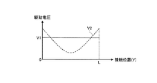
操作パネル10が振動する場合、保持部30が固定端となるため、操作パネル10は、保持部30に近いほど振動しにくく、保持部30から離れるほど振動しやすい。そのため、図6の実線に示すように、振動制御部230が一定の駆動電圧V1で振動部20を振動させても、接触位置が保持部30に近い場合、ユーザが振動を感じにくくなる。一方、接触位置が保持部30から遠い場合、ユーザに与える振動が大きく、ユーザが振動を不快に感じる可能性がある。なお、図6は、振動制御部230の駆動電圧を説明するための図であり、図6の横軸は、図1A、図1BのY軸方向における接触位置を示している。そのため、接触位置がゼロに近いほど図1Bの左側の保持部30に近く、接触位置がLに近いほど右側の保持部30に近い。
When the
振動補正部242は、振動制御部230が振動部20を振動させる場合の駆動電圧を、図6の点線で示す駆動電圧V2に補正する。図6に示すように、駆動電圧V2は、接触位置が保持部30に近いほど、すなわち、ゼロやLに近いほど値が大きく、接触位置が操作面11の中央に近いほど値が小さい。
The vibration correction unit 242 corrects the drive voltage when the
このように、操作パネル10が振動しやすい中央付近の駆動電圧V2の値を小さくし、振動しにくい保持部30付近の駆動電圧V2の値を大きくすることで、ユーザに一定の振動を与えることができる。
As described above, by reducing the value of the driving voltage V2 near the center where the
なお、駆動電圧V2は、駆動電圧補正情報320として例えば実験やシミュレーション等によって算出され、記憶部300に予め記憶されているものとする。また、駆動電圧V2である駆動電圧補正情報320を、図6では接触位置と駆動電圧V2の値との関係を示すグラフとして示しているがこれに限定されない。例えば、駆動電圧補正情報320を接触位置と駆動電圧V2との関係を示すマップや表として記憶部300が記憶するようにしてもよい。また、操作面11を複数の領域に分割し、領域ごとに駆動電圧V2を設定するようにしてもよい。
The drive voltage V2 is calculated as drive
また、図6では、Y軸方向において値が変化する駆動電圧V2を示しているが、これに限定されない。例えば、操作パネル10の長辺10c方向(X軸方向)においても駆動電圧V2の値を変化させてもよい。これは、図1Aに示すように、操作パネル10の短辺10d付近に振動部20が設けられるためである。このように、振動部20が配置されることで、振動部20付近では操作パネル10の振動様態が変化する。そこで、長辺10c方向(X軸方向)においても駆動電圧V2の値を変化させることで、操作パネル10の振動しやすさに応じて閾値を補正することができる。
6 shows the drive voltage V2 whose value changes in the Y-axis direction, the present invention is not limited to this. For example, the value of the drive voltage V2 may be changed also in the
このように、長辺10c方向においても駆動電圧V2の値を変化させる場合、例えば複数の振動部20の全てを振動させるか否かに応じて駆動電圧V2を変更するようにしてもよい。例えば、図1Aに示す2個の振動部20の両方を振動させる場合と、一方の振動部20を振動させ他方の振動部20を振動させない場合とでは操作面11の振動のしやすさが変化する。これは、振動部20が操作面11に接着固定されていることから、振動させない振動部20付近が振動しにくくなるためである。そこで、駆動電圧V2を補正する場合、複数の振動部20のうち振動させる振動部20に応じて駆動電圧V2を補正する。これにより、操作面11の構造に応じてより精度よく駆動電圧V2を補正することができる。
Thus, when changing the value of the drive voltage V2 also in the
振動補正部242は、駆動電圧補正情報320に基づき、位置検出部210が検出した接触位置における駆動電圧V2を決定し、決定した駆動電圧V2を振動制御部230に出力することで、振動制御部230による振動部20の振動制御を補正する。
The vibration correction unit 242 determines the drive voltage V2 at the contact position detected by the
なお、ここでは、図5、図6に示すように、操作面11の中央ほど閾値Th1の値が大きい、あるいは駆動電圧V2の値が小さいとしたが、これに限定されない。閾値Th1および駆動電圧V2は、操作パネル10のたわみやすさ、または、振動のしやすさに応じて決定されればよい。操作パネル10のたわみやすさ、振動のしやすさは、操作パネル10の材質、形状、あるいは保持部30の配置や形状等によって変化する。閾値Th1、駆動電圧V2は、例えば保持部30と接触位置との距離によって変化する値であり、上述したように、実験やシミュレーション等によって設定される値である。
Here, as shown in FIGS. 5 and 6, it is assumed that the value of the threshold Th1 is larger or the value of the drive voltage V2 is smaller toward the center of the
このように、閾値Th1、駆動電圧V2を、例えば保持部30と接触位置との距離に応じて設定することで、操作パネル10のたわみやすさ、振動しやすさに応じて操作検出部220で用いる閾値および振動部20の振動をより精度よく補正することができる。
As described above, the threshold value Th1 and the drive voltage V2 are set according to the distance between the holding
<4.制御処理>
次に、図7を用いて実施形態に係る入力装置1が実行する処理手順について説明する。図7は、実施形態に係る入力装置1が実行する処理手順を示すフローチャートである。なお、かかる処理手順は、制御装置200の制御部200aによって繰り返し行われる。
<4. Control processing>
Next, a processing procedure executed by the
まず、制御部200aの位置検出部210は、操作パネル10の検出結果に基づき、接触位置を検出する(ステップS101)。次に、閾値補正部241は、閾値補正情報310を記憶部300から取得し(ステップS102)、操作検出部220で用いる閾値を補正する(ステップS103)。
First, the
続いて、振動補正部242は、駆動電圧補正情報320を記憶部300から取得し(ステップS104)、振動制御部230が制御する振動部20の駆動電圧を補正する(ステップS105)。
Subsequently, the vibration correction unit 242 acquires the drive
次に、制御部200aは、操作検出部220が入力操作を検出したか否かを判定する(ステップS106)。入力操作を検出しない場合(ステップS106のNo)、ステップS101に戻る。一方、入力操作を検出した場合(ステップS106のYes)、制御部200aは押下操作を検出したか否かを判定する(ステップS107)。
Next, the control unit 200a determines whether or not the
押下操作を検出した場合(ステップS107のYes)、振動制御部230は、押下操作に応じた周波数およびステップS105で補正された駆動電圧で振動部20を振動させる(ステップS108)。一方、押下操作を検出しなかった場合(ステップS107のNo)、操作検出部220が検出した入力操作に応じた周波数およびステップS105で補正された駆動電圧で振動部20を振動させる(ステップS109)。
When the pressing operation is detected (Yes in step S107), the
なお、ステップS102、S103とステップS104、S105とは、順番を入れ替えてもよく、同時に処理を行ってもよい。 Note that the order of steps S102 and S103 and steps S104 and S105 may be interchanged, or the processes may be performed simultaneously.
また、図7では、位置検出部210が接触位置を検出してから閾値補正部241および振動補正部242が閾値Th1および駆動電圧V2を補正するとしたが、これに限定されない。例えば、入力装置1の電源オン時や製品出荷時のタイミングで閾値補正部241および振動補正部242が閾値Th1および駆動電圧V2を補正するようにしてもよい。この場合、操作検出部220および振動制御部230は、補正後の閾値Th1および駆動電圧V2を参照して入力操作の検出および振動部20の振動制御を行うものとする。
In FIG. 7, the threshold value correction unit 241 and the vibration correction unit 242 correct the threshold value Th1 and the driving voltage V2 after the
上述したように、実施形態に係る制御装置200は、位置検出部210と、操作検出部220と、振動制御部230と、補正部240とを備える。位置検出部210は、操作面11に対する接触位置を検出する。操作検出部220は、操作面11に対する接触操作を検出する。振動制御部230は、少なくとも一つの振動素子を制御して、操作面11を振動させる。補正部240は、操作面11における接触位置に基づき、操作検出部220による接触操作の検出および振動制御部230による操作面11の振動の少なくとも一方を補正する。
As described above, the
これにより、ユーザは操作面11における接触位置によらず一定の押圧力で押下操作を行うことができる。あるいは、ユーザは操作面11における接触位置によらず一定の振動を感じることができる。したがって、実施形態に係る入力装置1は、ユーザの操作性を向上させることができる。
Thereby, the user can perform the pressing operation with a constant pressing force regardless of the contact position on the
上記実施形態では、操作面11における接触位置に基づき、操作検出部220による押下操作の検出および振動制御部230による振動制御を補正するとしたが、これに限定されない。例えば接触位置に加え、操作面11の温度に応じて補正するようにしてもよい。操作パネル10のたわみやすさ、振動しやすさは温度によっても変化する。そこで、例えば図示しない温度センサによって入力装置1周辺の温度あるいは操作パネル10の温度を検出し、温度センサが検出した温度に基づいて、操作検出部220による押下操作の検出および振動制御部230による振動制御を補正するようにしてもよい。具体的には、接触面11の温度ごとに接触位置と閾値Th1または駆動電圧V2との関係を示すマップや表等が、記憶部300に閾値補正情報310または駆動電圧補正情報320として記憶されているものとする。補正部240は、温度センサが検出した温度に応じた閾値補正情報310または駆動電圧補正情報320を参照することで閾値Th1または駆動電圧V2を補正する。
In the above embodiment, the detection of the pressing operation by the
このように、入力装置1周辺の温度等を検出することで、操作面11の温度に応じて補正部240が補正を行うことができるため、補正部240がより精度よく補正を行うことができる。
As described above, since the
また、操作パネル10は、経年劣化によっても、操作パネル10のたわみやすさ、振動しやすさが変化する場合がある。そこで、例えば時間経過に応じて、操作検出部220による押下操作の検出および振動制御部230による振動制御を補正するようにしてもよい。例えば入力装置1が図示しない出荷時からの経過時間をカウントし、カウントした経過時間に基づいて操作検出部220による押下操作の検出および振動制御部230による振動制御を補正するようにしてもよい。具体的には、経過時間ごとに接触位置と閾値Th1または駆動電圧V2との関係を示すマップや表等が、記憶部300に閾値補正情報310または駆動電圧補正情報320として記憶されているものとする。補正部240は、タイマがカウントした経過時間に応じた閾値補正情報310または駆動電圧補正情報320を参照することで閾値Th1または駆動電圧V2を補正する。
Further, the
これにより、経年劣化による操作パネル10の変化に応じて、操作検出部220による押下操作の検出および振動制御部230による振動制御を補正することができ、補正部240による補正の精度を向上させることができる。
Accordingly, the detection of the pressing operation by the
また、上記実施形態では、振動部20の振動周波数によらず補正する駆動電圧V2を設定するとしたが、これに限定されない。例えば振動部20を高周波で振動させる場合と低周波で振動させる場合とでは操作パネル10の振動のしやすさが変化する可能性がある。そのため、振動部20を振動させる様態ごとに補正する駆動電圧V2を設定するようにしてもよい。
In the above embodiment, the drive voltage V2 to be corrected is set regardless of the vibration frequency of the
これにより、振動部20を振動させる様態ごとに振動部20の駆動電圧を補正することができ、振動部20の振動周波数が異なる場合であっても、接触位置によらず一定の振動をユーザに与えることができる。
Thereby, the drive voltage of the
また、上記実施形態では、記憶部300が閾値補正情報310および駆動電圧補正情報320を記憶するとしたが、これに限定されない。例えば、記憶部300が操作面11のたわみやすさ(または振動のしやすさ)を示す値を含む情報を記憶するようにしてもよい。この場合、例えば補正部240が、閾値を補正する場合は、閾値をかかる値を乗算し、駆動電圧を補正する場合は駆動電圧をかかる値で除算することで、閾値および駆動電圧を補正する。なお、補正部240による演算は一例であり、記憶部300に記憶される情報の値に応じた演算が行われればよい。
Moreover, in the said embodiment, although the memory | storage part 300 memorize | stored the threshold value correction information 310 and the drive
このように、1つの情報を用いて、補正部240が閾値および駆動電圧を補正することで、記憶部300に記憶される情報量を低減することができる。
Thus, the amount of information stored in the storage unit 300 can be reduced by the
さらなる効果や変形例は、当業者によって容易に導き出すことができる。このため、本発明のより広範な様態は、以上のように表しかつ記述した特定の詳細および代表的な実施形態に限定されるものではない。したがって、添付の特許請求の範囲および、その均等物によって定義される統括的な発明の概念の精神または範囲から逸脱することなく、様々な変化が可能である。 Further effects and modifications can be easily derived by those skilled in the art. Thus, the broader aspects of the present invention are not limited to the specific details and representative embodiments shown and described above. Accordingly, various modifications can be made without departing from the spirit or scope of the general inventive concept as defined by the appended claims and their equivalents.
1 入力装置
10 操作パネル
11 操作面
20 振動部
30 保持部
100 入力部
200 制御装置
210 位置検出部
220 操作検出部
230 振動制御部
240 補正部
241 閾値補正部
242 振動補正部
DESCRIPTION OF
Claims (9)
前記操作面に対する接触操作を検出する操作検出部と、
少なくとも一つの振動素子を制御して、前記操作面を振動させる振動制御部と、
前記操作面における前記接触位置に基づき、前記操作検出部による前記接触操作の検出および前記振動制御部による前記操作面の振動の少なくとも一方を補正する補正部と、
を備える制御装置。 A position detection unit for detecting a contact position on the operation surface;
An operation detection unit for detecting a contact operation on the operation surface;
A vibration control unit that controls at least one vibration element to vibrate the operation surface;
A correction unit that corrects at least one of detection of the contact operation by the operation detection unit and vibration of the operation surface by the vibration control unit based on the contact position on the operation surface;
A control device comprising:
前記操作面を含む操作パネルの構造に応じた前記接触位置に基づき、前記操作検出部による前記接触操作の検出および前記振動制御部による前記操作面の振動の少なくとも一方を補正する請求項1に記載の制御装置。 The correction unit is
The correction of at least one of the detection of the contact operation by the operation detection unit and the vibration of the operation surface by the vibration control unit based on the contact position according to the structure of the operation panel including the operation surface. Control device.
前記操作面を保持する保持部と前記接触位置との距離に応じて、前記操作検出部による前記接触操作の検出および前記振動制御部による前記操作面の振動の少なくとも一方を補正する請求項1または2に記載の制御装置。 The correction unit is
The correction of at least one of detection of the contact operation by the operation detection unit and vibration of the operation surface by the vibration control unit according to a distance between the holding unit that holds the operation surface and the contact position. 2. The control device according to 2.
前記接触位置が前記保持部に近いほど前記操作面の前記振動が大きくなるようにする請求項3に記載の制御装置。 The correction unit is
The control device according to claim 3, wherein the vibration of the operation surface is increased as the contact position is closer to the holding unit.
前記操作面に対して閾値以上の押し込み量で押下された場合に、前記操作面に対する押下操作を検出し、
前記補正部は、
前記接触位置が前記保持部に近いほど前記閾値が小さくなるように、前記閾値を補正する請求項3または4に記載の制御装置。 The operation detection unit is
When the operation surface is pressed with a pressing amount equal to or greater than a threshold, a pressing operation on the operation surface is detected,
The correction unit is
The control device according to claim 3 or 4, wherein the threshold value is corrected so that the threshold value becomes smaller as the contact position is closer to the holding unit.
前記操作面の温度に応じて前記操作検出部による前記接触操作の検出および前記振動制御部による前記操作面の振動の少なくとも一方を補正する請求項1〜5のいずれか一項に記載の制御装置。 The correction unit is
The control device according to claim 1, wherein at least one of detection of the contact operation by the operation detection unit and vibration of the operation surface by the vibration control unit is corrected according to a temperature of the operation surface. .
時間経過に応じて前記操作検出部による前記接触操作の検出および前記振動制御部による前記操作面の振動の少なくとも一方を補正する請求項1〜6のいずれか一項に記載の制御装置。 The correction unit is
The control device according to any one of claims 1 to 6, wherein at least one of detection of the contact operation by the operation detection unit and vibration of the operation surface by the vibration control unit is corrected according to the passage of time.
前記操作面に対する接触操作を検出し、
少なくとも一つの振動素子を制御して、前記操作面を振動させ、
前記操作面における前記接触位置に基づき、前記接触操作の検出および前記操作面の振動の少なくとも一方を補正する、制御方法。 Detect the contact position on the operation surface,
Detecting a contact operation on the operation surface;
Controlling at least one vibration element to vibrate the operation surface;
A control method for correcting at least one of detection of the contact operation and vibration of the operation surface based on the contact position on the operation surface.
前記操作面に対する接触位置を検出する位置検出部と、
前記操作面に対する接触操作を検出する操作検出部と、
前記少なくとも一つの振動素子を制御して、前記操作面を振動させる振動制御部と、
前記操作面における前記接触位置に基づき、前記操作検出部による前記接触操作の検出および前記振動制御部による前記操作面の振動の少なくとも一方を補正する補正部と、
を備える入力装置。 At least one vibration element for vibrating the operation surface;
A position detection unit for detecting a contact position with respect to the operation surface;
An operation detection unit for detecting a contact operation on the operation surface;
A vibration control unit that controls the at least one vibration element to vibrate the operation surface;
A correction unit that corrects at least one of detection of the contact operation by the operation detection unit and vibration of the operation surface by the vibration control unit based on the contact position on the operation surface;
An input device comprising:
Priority Applications (2)
| Application Number | Priority Date | Filing Date | Title |
|---|---|---|---|
| JP2017140344A JP2019021144A (en) | 2017-07-19 | 2017-07-19 | Control device, control method, and input device |
| US15/963,687 US10877598B2 (en) | 2017-07-19 | 2018-04-26 | Controller, control method, and input apparatus |
Applications Claiming Priority (1)
| Application Number | Priority Date | Filing Date | Title |
|---|---|---|---|
| JP2017140344A JP2019021144A (en) | 2017-07-19 | 2017-07-19 | Control device, control method, and input device |
Publications (2)
| Publication Number | Publication Date |
|---|---|
| JP2019021144A true JP2019021144A (en) | 2019-02-07 |
| JP2019021144A5 JP2019021144A5 (en) | 2020-08-27 |
Family
ID=65018926
Family Applications (1)
| Application Number | Title | Priority Date | Filing Date |
|---|---|---|---|
| JP2017140344A Pending JP2019021144A (en) | 2017-07-19 | 2017-07-19 | Control device, control method, and input device |
Country Status (2)
| Country | Link |
|---|---|
| US (1) | US10877598B2 (en) |
| JP (1) | JP2019021144A (en) |
Cited By (2)
| Publication number | Priority date | Publication date | Assignee | Title |
|---|---|---|---|---|
| JP2021026539A (en) * | 2019-08-06 | 2021-02-22 | レノボ・シンガポール・プライベート・リミテッド | Electronic equipment and control method |
| JPWO2020213477A1 (en) * | 2019-04-19 | 2021-09-13 | 株式会社村田製作所 | Vibration device |
Citations (7)
| Publication number | Priority date | Publication date | Assignee | Title |
|---|---|---|---|---|
| JPH0764725A (en) * | 1993-08-26 | 1995-03-10 | Philips Electron Nv | Data processor with touch screen and with force sensor |
| JP2005258666A (en) * | 2004-03-10 | 2005-09-22 | Sony Corp | Input device, electronic device, and method for inputting touch to electronic device as feedback |
| JP2012155630A (en) * | 2011-01-27 | 2012-08-16 | Kyocera Corp | Object display device |
| JP2012226478A (en) * | 2011-04-18 | 2012-11-15 | Kyocera Corp | Portable information terminal |
| JP2014216024A (en) * | 2013-04-26 | 2014-11-17 | イマージョンコーポレーションImmersion Corporation | System and method for haptically-enabled deformable surface |
| JP2016146035A (en) * | 2015-02-06 | 2016-08-12 | 京セラドキュメントソリューションズ株式会社 | Input device and electronic apparatus |
| WO2017018650A1 (en) * | 2015-07-24 | 2017-02-02 | 주식회사 하이딥 | Touch pressure sensitivity correction method and computer-readable recording medium |
Family Cites Families (5)
| Publication number | Priority date | Publication date | Assignee | Title |
|---|---|---|---|---|
| JPWO2014125857A1 (en) | 2013-02-13 | 2017-02-02 | 日本電気株式会社 | INPUT DEVICE, ITS CONTROL METHOD, AND PROGRAM |
| WO2015136835A1 (en) * | 2014-03-13 | 2015-09-17 | パナソニックIpマネジメント株式会社 | Electronic device |
| KR101920013B1 (en) * | 2015-12-04 | 2018-11-19 | 주식회사 모다이노칩 | Touch screen apparatus |
| JP6613170B2 (en) * | 2016-02-23 | 2019-11-27 | 京セラ株式会社 | Vehicle control unit and control method thereof |
| WO2017201338A1 (en) * | 2016-05-18 | 2017-11-23 | Sensel Inc. | Method for detecting and confirming a touch input |
-
2017
- 2017-07-19 JP JP2017140344A patent/JP2019021144A/en active Pending
-
2018
- 2018-04-26 US US15/963,687 patent/US10877598B2/en active Active
Patent Citations (7)
| Publication number | Priority date | Publication date | Assignee | Title |
|---|---|---|---|---|
| JPH0764725A (en) * | 1993-08-26 | 1995-03-10 | Philips Electron Nv | Data processor with touch screen and with force sensor |
| JP2005258666A (en) * | 2004-03-10 | 2005-09-22 | Sony Corp | Input device, electronic device, and method for inputting touch to electronic device as feedback |
| JP2012155630A (en) * | 2011-01-27 | 2012-08-16 | Kyocera Corp | Object display device |
| JP2012226478A (en) * | 2011-04-18 | 2012-11-15 | Kyocera Corp | Portable information terminal |
| JP2014216024A (en) * | 2013-04-26 | 2014-11-17 | イマージョンコーポレーションImmersion Corporation | System and method for haptically-enabled deformable surface |
| JP2016146035A (en) * | 2015-02-06 | 2016-08-12 | 京セラドキュメントソリューションズ株式会社 | Input device and electronic apparatus |
| WO2017018650A1 (en) * | 2015-07-24 | 2017-02-02 | 주식회사 하이딥 | Touch pressure sensitivity correction method and computer-readable recording medium |
Cited By (3)
| Publication number | Priority date | Publication date | Assignee | Title |
|---|---|---|---|---|
| JPWO2020213477A1 (en) * | 2019-04-19 | 2021-09-13 | 株式会社村田製作所 | Vibration device |
| JP7143941B2 (en) | 2019-04-19 | 2022-09-29 | 株式会社村田製作所 | vibration device |
| JP2021026539A (en) * | 2019-08-06 | 2021-02-22 | レノボ・シンガポール・プライベート・リミテッド | Electronic equipment and control method |
Also Published As
| Publication number | Publication date |
|---|---|
| US10877598B2 (en) | 2020-12-29 |
| US20190025983A1 (en) | 2019-01-24 |
Similar Documents
| Publication | Publication Date | Title |
|---|---|---|
| JP6351964B2 (en) | Input device | |
| WO2015045063A1 (en) | Drive control apparatus, electronic device, and drive control method | |
| JP7038552B2 (en) | Operation input device and touch panel | |
| JP5689362B2 (en) | Input device | |
| JP7141215B2 (en) | Operation input device and touch panel | |
| JP6599242B2 (en) | Input device | |
| JP2018036959A (en) | Control device, input device, input system, display device, and control method | |
| US20140375602A1 (en) | Tactile presentation apparatus and tactile presentation method | |
| US10656716B2 (en) | Control device, input system, and control method | |
| JP2019021144A (en) | Control device, control method, and input device | |
| US10664056B2 (en) | Control device, input system and control method | |
| US20180348873A1 (en) | Input device | |
| JP2018160244A (en) | Haptic effect using high bandwidth thin actuation system | |
| JP2017004262A (en) | Manipulation device | |
| US20170090575A1 (en) | Tactile-sensation transmitting device, terminal device, and tactile-sensation transmitting method | |
| JP6755216B2 (en) | Input device and input system | |
| JP7103782B2 (en) | Input device and input control device | |
| JP2018005780A (en) | Manipulation device | |
| US10725547B2 (en) | Input device | |
| JP6709628B2 (en) | Input device and display device | |
| US10802590B2 (en) | Input device | |
| WO2015129287A1 (en) | Input device | |
| JP2017090993A (en) | Haptic feedback device | |
| JP2017004263A (en) | Haptic feedback device | |
| JP2017072901A (en) | Tactile sense presentation device |
Legal Events
| Date | Code | Title | Description |
|---|---|---|---|
| A521 | Request for written amendment filed |
Free format text: JAPANESE INTERMEDIATE CODE: A523 Effective date: 20200715 |
|
| A621 | Written request for application examination |
Free format text: JAPANESE INTERMEDIATE CODE: A621 Effective date: 20200715 |
|
| A871 | Explanation of circumstances concerning accelerated examination |
Free format text: JAPANESE INTERMEDIATE CODE: A871 Effective date: 20200715 |
|
| A975 | Report on accelerated examination |
Free format text: JAPANESE INTERMEDIATE CODE: A971005 Effective date: 20201002 |
|
| A131 | Notification of reasons for refusal |
Free format text: JAPANESE INTERMEDIATE CODE: A131 Effective date: 20201006 |
|
| A02 | Decision of refusal |
Free format text: JAPANESE INTERMEDIATE CODE: A02 Effective date: 20210406 |