JP2019018627A - Pedal recession prevention structure - Google Patents
Pedal recession prevention structure Download PDFInfo
- Publication number
- JP2019018627A JP2019018627A JP2017136556A JP2017136556A JP2019018627A JP 2019018627 A JP2019018627 A JP 2019018627A JP 2017136556 A JP2017136556 A JP 2017136556A JP 2017136556 A JP2017136556 A JP 2017136556A JP 2019018627 A JP2019018627 A JP 2019018627A
- Authority
- JP
- Japan
- Prior art keywords
- pedal
- car beam
- cross car
- center stay
- extending portion
- Prior art date
- Legal status (The legal status is an assumption and is not a legal conclusion. Google has not performed a legal analysis and makes no representation as to the accuracy of the status listed.)
- Pending
Links
Images


Classifications
-
- B—PERFORMING OPERATIONS; TRANSPORTING
- B60—VEHICLES IN GENERAL
- B60T—VEHICLE BRAKE CONTROL SYSTEMS OR PARTS THEREOF; BRAKE CONTROL SYSTEMS OR PARTS THEREOF, IN GENERAL; ARRANGEMENT OF BRAKING ELEMENTS ON VEHICLES IN GENERAL; PORTABLE DEVICES FOR PREVENTING UNWANTED MOVEMENT OF VEHICLES; VEHICLE MODIFICATIONS TO FACILITATE COOLING OF BRAKES
- B60T7/00—Brake-action initiating means
- B60T7/02—Brake-action initiating means for personal initiation
- B60T7/04—Brake-action initiating means for personal initiation foot actuated
- B60T7/06—Disposition of pedal
- B60T7/065—Disposition of pedal with means to prevent injuries in case of collision
-
- B—PERFORMING OPERATIONS; TRANSPORTING
- B60—VEHICLES IN GENERAL
- B60R—VEHICLES, VEHICLE FITTINGS, OR VEHICLE PARTS, NOT OTHERWISE PROVIDED FOR
- B60R21/00—Arrangements or fittings on vehicles for protecting or preventing injuries to occupants or pedestrians in case of accidents or other traffic risks
- B60R21/02—Occupant safety arrangements or fittings, e.g. crash pads
- B60R21/09—Control elements or operating handles movable from an operative to an out-of-the way position, e.g. pedals, switch knobs, window cranks
-
- B—PERFORMING OPERATIONS; TRANSPORTING
- B62—LAND VEHICLES FOR TRAVELLING OTHERWISE THAN ON RAILS
- B62D—MOTOR VEHICLES; TRAILERS
- B62D21/00—Understructures, i.e. chassis frame on which a vehicle body may be mounted
-
- G—PHYSICS
- G05—CONTROLLING; REGULATING
- G05G—CONTROL DEVICES OR SYSTEMS INSOFAR AS CHARACTERISED BY MECHANICAL FEATURES ONLY
- G05G1/00—Controlling members, e.g. knobs or handles; Assemblies or arrangements thereof; Indicating position of controlling members
- G05G1/30—Controlling members actuated by foot
- G05G1/32—Controlling members actuated by foot with means to prevent injury
Abstract
Description
本発明はペダル後退防止構造体に関する。 The present invention relates to a pedal retreat prevention structure.
車両においては、車両前方での衝突等により後方への荷重を受けたとき、ペダルの後退を防止するためのペダル後退防止構造体が設けられている。例えば、衝突により後方への荷重を受けると、ブレーキペダルが後退し、当該ブレーキペダルを踏み込んだ運転者の足に、当該ブレーキペダルから荷重が入力される。これを軽減するために、ペダル後退防止構造体が使用されている。 The vehicle is provided with a pedal retraction preventing structure for preventing the pedal from retreating when a load is applied rearward due to a collision or the like in front of the vehicle. For example, when a rearward load is received due to a collision, the brake pedal moves backward, and the load is input from the brake pedal to the foot of the driver who has depressed the brake pedal. In order to alleviate this, a pedal retraction prevention structure is used.
このようなペダル後退防止構造体として、例えば、円筒状クロスカービームおよび当該円筒状クロスカービームに支持されつつ、ブレーキペダルの後退を防止するペダル後退防止部材を含むペダル後退防止構造体が知られている(例えば特許文献1)。 As such a pedal reverse prevention structure, for example, a pedal reverse prevention structure including a cylindrical cross car beam and a pedal reverse prevention member that is supported by the cylindrical cross car beam and prevents the brake pedal from retreating is known. (For example, Patent Document 1).
本発明の発明者等は、従来の技術では、ペダル後退防止部材により、ブレーキペダル由来の後方への荷重を受けたとき、クロスカービームが比較的容易に破壊され、クロスカービームの機械強度(特に剛性)が新たな問題となることを見い出した。このような問題は、クロスカービームが軽量化のために、繊維強化樹脂から構成されたり、または中空体から構成されたりしたとき、特に顕著であった。 In the prior art, the inventors of the present invention, in the conventional technique, when the rearward load derived from the brake pedal is received by the pedal reverse prevention member, the crosscar beam is relatively easily broken, and the mechanical strength of the crosscar beam ( It was found that (especially rigidity) becomes a new problem. Such a problem is particularly prominent when the cross car beam is made of a fiber reinforced resin or a hollow body for weight reduction.
本発明は、より良好な衝突性能を有するペダル後退防止構造体を提供することを目的とする。 An object of the present invention is to provide a pedal retreat prevention structure having better collision performance.
本発明は、より良好な衝突性能を有するとともに、より一層の軽量化が達成されているペダル後退防止構造体を提供することを目的とする。 An object of the present invention is to provide a pedal retraction prevention structure that has better collision performance and is further reduced in weight.
本発明は、
軸方向に延びるクロスカービーム;
前記クロスカービームに支持されつつ、ブレーキペダルの後退を防止するペダル後退防止部材;および
前記クロスカービームを支持するセンタステイを含むペダル後退防止構造体であって、
前記ペダル後退防止部材が、車両の前後方向において、前記センタステイの前方に配置されている、ペダル後退防止構造体に関する。
The present invention
Crosscar beam extending in the axial direction;
A pedal retraction preventing member that prevents a brake pedal from retreating while being supported by the cross car beam; and a pedal retreat prevention structure including a center stay that supports the cross car beam,
The present invention relates to a pedal reverse prevention structure in which the pedal reverse prevention member is disposed in front of the center stay in the longitudinal direction of the vehicle.
本発明のペダル後退防止構造体は、より良好な衝突性能を有する。
本発明のペダル後退防止構造体は、より良好な衝突性能を有するとともに、より一層の軽量化を達成することができる。
The pedal retreat prevention structure of the present invention has better collision performance.
The pedal retreat prevention structure according to the present invention has better collision performance and can achieve further weight reduction.
[ペダル後退防止構造体]
本発明のペダル後退防止構造体は、車両前方での衝突等により後方への荷重を受けたとき、ブレーキペダルを踏み込んだ運転者の足への当該荷重の入力を軽減するための構造体である。本明細書中、車両は、自動車、バス、トラック、電車(鉄道車両)等の車両だけでなく、ステアリング装置を備えたあらゆる乗り物(運搬装置)を含む概念で用いるものとし、例えば、上記した車両だけでなく、航空機、および船舶等を包含する。
[Pedal retraction prevention structure]
The pedal retraction prevention structure of the present invention is a structure for reducing the input of the load to the foot of the driver who stepped on the brake pedal when receiving a backward load due to a collision or the like in front of the vehicle. . In this specification, the vehicle is used in a concept including not only vehicles such as automobiles, buses, trucks, and trains (railcars) but also any vehicle (transport device) provided with a steering device. As well as aircraft and ships.
本明細書中、「衝突性能」は、主としてクロスカービームの機械的性能(特に剛性)に基づく性能であって、車両前方からの衝突によってもクロスカービームの断面破断に至り難い性能(耐衝突性能)のことである。
「ステアリング振動性能」とは、ペダル後退防止構造体に入力された振動が車両内のステアリング装置に伝導されるのを防止し、振動に基づく運転者および同乗者等の乗員への不快感を軽減する性能のことである。ステアリング装置は操舵装置であって、例えば、自動車におけるハンドルのことである。
In this specification, “collision performance” is performance based mainly on the mechanical performance (particularly rigidity) of the crosscar beam, and is a performance that does not easily cause a cross-sectional fracture of the crosscar beam even from a collision from the front of the vehicle (impact resistance). Performance).
“Steering vibration performance” means that vibrations input to the pedal retraction prevention structure are prevented from being transmitted to the steering device in the vehicle, reducing discomfort to the driver and passengers such as passengers based on the vibration. It is the performance to do. The steering device is a steering device, for example, a steering wheel in an automobile.
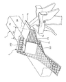
以下、本発明のペダル後退防止構造体を図面に基づいて説明する。図1は、本発明の一実施態様に係るペダル後退防止構造体の模式的斜視図である。図2は、図1のペダル後退防止構造体とブレーキペダルの側面図である。図3は、図1のペダル後退防止構造体におけるペダル後退防止部材近傍の拡大斜視図である。図4は、本発明の別の一実施態様に係るペダル後退防止構造体におけるペダル後退防止部材近傍の拡大斜視図である。図5は、本発明のまた別の一実施態様に係るペダル後退防止構造体におけるペダル後退防止部材近傍の拡大斜視図である。 Hereinafter, the pedal retreat prevention structure of the present invention is explained based on a drawing. FIG. 1 is a schematic perspective view of a pedal retreat prevention structure according to an embodiment of the present invention. FIG. 2 is a side view of the pedal retreat prevention structure and the brake pedal of FIG. FIG. 3 is an enlarged perspective view of the vicinity of a pedal retraction preventing member in the pedal retraction preventing structure of FIG. FIG. 4 is an enlarged perspective view of the vicinity of a pedal retraction preventing member in a pedal retraction preventing structure according to another embodiment of the present invention. FIG. 5 is an enlarged perspective view of the vicinity of a pedal retraction preventing member in a pedal retraction preventing structure according to another embodiment of the present invention.
図中において矢印Fは車両前方、矢印Rは車両後方を示している。矢印Wは車幅方向を示し、矢印Wdは車幅方向Wにおけるステアリング支持部材が配置された運転席側を示し、矢印Wpは車幅方向Wにおける助手席側を示している。矢印Hrは車両高さのルーフ方向、矢印Hfは車両高さのフロア方向を示している。図面に示す各種の要素は、本発明の理解のために模式的に示したにすぎず、寸法比および外観などは実物と異なり得ることに留意されたい。尚、本明細書で直接的または間接的に用いる「上下方向」は、特記しない限り、ペダル後退防止構造体を車両に適用したときに対応する上下方向に相当する。これらの図において、共通する符号は、特記しない限り、同じ部材、部位、寸法または領域を示すものとする。 In the figure, arrow F indicates the front of the vehicle, and arrow R indicates the rear of the vehicle. The arrow W indicates the vehicle width direction, the arrow Wd indicates the driver seat side where the steering support member is disposed in the vehicle width direction W, and the arrow Wp indicates the passenger seat side in the vehicle width direction W. Arrow Hr indicates the roof direction of the vehicle height, and arrow Hf indicates the floor direction of the vehicle height. It should be noted that the various elements shown in the drawings are merely schematically shown for understanding of the present invention, and the dimensional ratio and appearance may differ from the actual ones. It should be noted that the “vertical direction” used directly or indirectly in the present specification corresponds to the vertical direction corresponding to when the pedal retreat prevention structure is applied to a vehicle, unless otherwise specified. In these drawings, common reference numerals indicate the same members, parts, dimensions, or regions unless otherwise specified.
本発明のペダル後退防止構造体10は、クロスカービーム1、センタステイ3、およびペダル後退防止部材7を含み、通常は、ステアリング支持部材2およびサイドブラケット4をさらに含む。
The pedal
(クロスカービーム)
クロスカービーム1は軸方向にて延びる部材である。クロスカービーム1の軸方向に対して垂直な断面視形状は特に限定されず、例えば、円形状、半円形状または扇形形状であってもよいし、または矩形状等を含む多角形状であってもよい。クロスカービーム1の断面視形状は矩形状であることが好ましい。これにより、ペダル後退防止構造体の衝突性能がさらに向上する。矩形状は正方形状および長方形状を含む概念で用いるものとし、上記の観点から、正方形状が好ましい。クロスカービーム1の断面視形状が矩形状のとき、当該クロスカービーム1は全体として角柱形状を有する。なお角柱形状は、クロスカービーム1がその断面視形状として矩形状を有し、かつ後述の中空体である場合も包含する。
(Cross car beam)
The cross car beam 1 is a member extending in the axial direction. The cross-sectional shape perpendicular to the axial direction of the crosscar beam 1 is not particularly limited, and may be, for example, a circular shape, a semicircular shape, a sector shape, or a polygonal shape including a rectangular shape. Also good. The cross-sectional shape of the cross car beam 1 is preferably rectangular. Thereby, the collision performance of the pedal retreat prevention structure is further improved. The rectangular shape is used in a concept including a square shape and a rectangular shape, and the square shape is preferable from the above viewpoint. When the cross-sectional shape of the cross car beam 1 is rectangular, the cross car beam 1 has a prismatic shape as a whole. The prismatic shape includes a case where the cross car beam 1 has a rectangular shape as a cross-sectional view and is a hollow body described later.
クロスカービーム1が断面視形状として矩形状を有するとき、クロスカービーム1は前面、後面、上面および下面を有する。クロスカービーム1の前面、後面、上面および下面とはそれぞれ、クロスカービーム1において車両の前方(F)、後方(R)、ルーフ方向(Hr)およびフロア方向(Hf)を向いている面という意味であり、例えば図2においてそれぞれ1a、1b、1cおよび1dで示される。クロスカービーム1は通常、その軸方向が車両の車幅方向に平行になるように配置される。 When the cross car beam 1 has a rectangular shape as a sectional view, the cross car beam 1 has a front surface, a rear surface, an upper surface, and a lower surface. The front surface, the rear surface, the upper surface, and the lower surface of the cross car beam 1 are surfaces facing the front (F), rear (R), roof direction (Hr), and floor direction (Hf) of the vehicle in the cross car beam 1, respectively. Meaning, for example, 1a, 1b, 1c and 1d respectively in FIG. The cross car beam 1 is usually arranged so that its axial direction is parallel to the vehicle width direction of the vehicle.
クロスカービーム1は中空体であることが好ましい。これにより、ペダル後退防止構造体の軽量化を達成することができる。中空体を構成する材料は特に限定されず、例えば、アルミニウム、鉄、鉄鋼およびこれらの合金等の金属であってもよいし、ポリマー等の樹脂であってもよいし、または繊維強化樹脂であってもよい。中空体を構成する材料は、さらなる軽量化と、衝突性能のさらなる向上とのバランスの観点から、繊維強化樹脂であることが好ましい。本発明において軽量化は、主として、クロスカービーム1が繊維強化樹脂中空体であること、およびペダル後退防止部材7がポリマー材料から構成されることにより達成される。
The cross car beam 1 is preferably a hollow body. Thereby, the weight reduction of the pedal retreat prevention structure can be achieved. The material constituting the hollow body is not particularly limited, and may be a metal such as aluminum, iron, steel, and alloys thereof, a resin such as a polymer, or a fiber reinforced resin. May be. The material constituting the hollow body is preferably a fiber reinforced resin from the viewpoint of a balance between further weight reduction and further improvement in collision performance. In the present invention, weight reduction is achieved mainly by the fact that the cross car beam 1 is a fiber-reinforced resin hollow body and that the pedal
繊維強化樹脂中空体は、全体形状として、長尺形状を有する硬化性樹脂の含浸体である。繊維強化樹脂中空体は、強化繊維を含む繊維層および当該繊維層に含浸され硬化された硬化性樹脂を含む中空体であれば特に限定されない。繊維層における繊維は硬化性樹脂中に均一に分散されていてもよいが、衝突性能のさらなる向上の観点から、繊維層は軸方向繊維層を含むことが好ましい。軸方向繊維層とは、クロスカービームの軸方向(長手方向)に対して平行に配向する強化繊維を主として含む繊維層のことであり、本発明においては衝突性能のさらなる向上の観点から強化繊維のみからなる繊維層が好ましい。 The fiber reinforced resin hollow body is an impregnated body of a curable resin having a long shape as an overall shape. The fiber reinforced resin hollow body is not particularly limited as long as it is a hollow body containing a fiber layer containing reinforcing fibers and a curable resin impregnated and cured in the fiber layer. The fibers in the fiber layer may be uniformly dispersed in the curable resin, but the fiber layer preferably includes an axial fiber layer from the viewpoint of further improving the impact performance. The axial fiber layer is a fiber layer mainly containing reinforcing fibers oriented parallel to the axial direction (longitudinal direction) of the cross car beam. In the present invention, the reinforcing fibers are used from the viewpoint of further improving the impact performance. A fiber layer consisting only of is preferred.
強化繊維は、従来から繊維強化プラスチックの分野で使用されているあらゆる繊維が使用可能であり、例えば、ガラス繊維、炭素繊維が挙げられる。好ましい強化繊維はガラス繊維である。 As the reinforcing fiber, any fiber conventionally used in the field of fiber-reinforced plastic can be used, and examples thereof include glass fiber and carbon fiber. A preferred reinforcing fiber is glass fiber.
硬化性樹脂としては、従来から繊維強化樹脂中空体に使用される、あらゆる硬化性樹脂が使用可能である。硬化性樹脂の具体例として、例えば、不飽和ポリエステル樹脂、エポキシ樹脂、ビニルエステル樹脂、フェノール樹脂樹脂等の熱硬化性樹脂が挙げられる。 As the curable resin, any curable resin conventionally used for fiber-reinforced resin hollow bodies can be used. Specific examples of the curable resin include thermosetting resins such as unsaturated polyester resins, epoxy resins, vinyl ester resins, and phenol resin resins.
硬化性樹脂は、いわゆる触媒、離形剤、顔料、低収縮剤、シランカップリング剤等の添加剤を含有してもよい。 The curable resin may contain additives such as a so-called catalyst, a release agent, a pigment, a low shrinkage agent, and a silane coupling agent.
クロスカービーム1が中空体である場合、クロスカービーム1はいかなる厚みを有していてもよく、用途に応じて適宜、決定されればよい。ペダル後退防止構造体を車両、特に自動車の用途で用いる場合、クロスカービーム1は、ペダル後退防止構造体のさらなる軽量化および衝突性能のさらなる向上の観点から、通常は1〜20mm、特に1〜10mm、好ましくは1〜3mmの厚みを有する。厚みとは肉厚のことである。 When the cross car beam 1 is a hollow body, the cross car beam 1 may have any thickness and may be appropriately determined according to the application. When the pedal reverse prevention structure is used in a vehicle, particularly an automobile, the cross car beam 1 is usually 1 to 20 mm, particularly 1 to 20 mm, from the viewpoint of further reducing the weight of the pedal reverse prevention structure and further improving the collision performance. It has a thickness of 10 mm, preferably 1 to 3 mm. Thickness is the thickness.
クロスカービーム1はいかなる外周長を有していてよく、用途に応じて適宜、決定されればよい。ペダル後退防止構造体を車両、特に自動車の用途で用いる場合、クロスカービーム1は、例えば、125〜300mmの外周長を有する。クロスカービーム1の外周長とは、軸方向に対する垂直断面におけるクロスカービーム1の外周長のことである。クロスカービーム1が矩形状の断面視形状を有する場合、クロスカービーム1の垂直断面形状における一辺の長さは特に限定されず、例えば45〜75mmである。 The cross car beam 1 may have any outer peripheral length, and may be appropriately determined according to the application. When the pedal retraction preventing structure is used in a vehicle, particularly an automobile, the cross car beam 1 has an outer peripheral length of, for example, 125 to 300 mm. The outer peripheral length of the cross car beam 1 is the outer peripheral length of the cross car beam 1 in a cross section perpendicular to the axial direction. When the cross car beam 1 has a rectangular cross-sectional view shape, the length of one side in the vertical cross-sectional shape of the cross car beam 1 is not particularly limited, and is, for example, 45 to 75 mm.
クロスカービーム1は引抜成形体であることが好ましい。引抜成形体の断面視形状は通常、その軸方向において一定である。クロスカービーム1が特に繊維強化樹脂中空体である場合、当該繊維強化樹脂中空体は、以下の引抜成形法により製造することができる。引抜成形法においては、例えば、軸方向繊維層を構成する強化繊維に硬化性樹脂を含浸させ、硬化性樹脂が含浸した強化繊維を、中空体の断面視形状を有する金型の一端側から引き込み、金型内で加熱により硬化性樹脂を十分に硬化させる。得られた繊維強化樹脂中空体は、金型から連続的に引き取り、切断機によって所定長さに切断する等、後加工する。 The cross car beam 1 is preferably a pultruded body. The cross-sectional shape of the pultruded body is usually constant in the axial direction. When the cross car beam 1 is a fiber reinforced resin hollow body, the fiber reinforced resin hollow body can be manufactured by the following pultrusion molding method. In the pultrusion method, for example, a reinforcing fiber constituting an axial fiber layer is impregnated with a curable resin, and the reinforcing fiber impregnated with the curable resin is drawn from one end side of a mold having a hollow body cross-sectional shape. The curable resin is sufficiently cured by heating in the mold. The obtained fiber-reinforced resin hollow body is continuously taken out from the mold and post-processed, such as being cut into a predetermined length by a cutting machine.
クロスカービーム1は複数の締結用ホールを有し、その形成位置により、クロスカービーム1と、センタステイ3、ペダル後退防止部材7、ステアリング支持部材2、サイドブラケット4および/または補強部材5との締結が達成され得る。本明細書中、締結は、リベット、ボルト、ネジ、ピン、ステープル、ストラップ、ステッチ、接着剤等のあらゆる締結具からなる群から選択される1種以上の締結具によって達成されてもよい。好ましい締結具はリベット、ボルト、ネジまたはピンであり、接着剤が併用されていてもよい。より好ましい締結具はリベットまたはボルトであり、接着剤が併用されていてもよい。本発明において、締結は、2つ以上の部材をまとめて固定する概念で用いるものとし、接着剤を併用した締結も包含する。また接着剤を併用した締結は、隣接する部材間に接着剤層が介在する締結のことであり、このような締結を「接合」というものとする。従って、本発明における全ての締結は、ペダル後退防止構造体10の衝突性能のさらなる向上の観点から、接合であることが好ましい。
The cross car beam 1 has a plurality of fastening holes. Depending on the formation position, the cross car beam 1, the
(ステアリング支持部材)
ペダル後退防止構造体10はステアリング支持部材2を含まなくてもよいが、ペダル後退防止構造体10の衝突性能のさらなる向上の観点からは、ステアリング支持部材2を含み、かつペダル後退防止部材7をステアリング支持部材と締結することが好ましい。同様の観点からは、ペダル後退防止構造体10は、ステアリング支持部材2および後述の補強部材5を含み、かつペダル後退防止部材7をステアリング支持部材2と締結しつつ、補強部材5をステアリング支持部材2およびセンタステイ3と締結することがより好ましい。
(Steering support member)
The pedal
ステアリング支持部材2は、クロスカービーム1に支持されつつ、ステアリング装置を支持する機能を有する。ステアリング支持部材2は通常、その前端部21で、いわゆるカウル(車体前部)(図示せず)からの前方−後方方向(F−R方向)の力を受けるようになっている。このため、衝突時においてクロスカービームの前進が防止される。ステアリング支持部材2は、ステアリング振動性能の向上の観点から、その前端部21がカウルまたは当該カウルと接続されたカウルブラケットに固定されていることが好ましい。ステアリング支持部材2の前端部21は、ステアリング支持部材2において車両前方方向F側の端部のことである。カウルは通常、車幅方向に延在する衝突性能向上のための部材であり、例えば自動車においては、ボンネットの最後方部分に配置されている。カウルとステアリング支持部材との固定は、直接的に達成されてもよいし、または棒状のカウルブラケットを介して間接的に達成されてもよい。ステアリング装置は操舵装置であって、例えば、自動車におけるハンドルのことである。
The steering support member 2 has a function of supporting the steering device while being supported by the cross car beam 1. The steering support member 2 normally receives a force in the front-rear direction (F-R direction) from a so-called cowl (front portion of the vehicle body) (not shown) at the
ステアリング支持部材2は複数の締結用ホールを有し、その形成位置により、ステアリング支持部材2と、ペダル後退防止部材7、クロスカービーム1および/または補強部材5との締結、ステアリング支持部材2とカウルとの締結が達成され得る。特にステアリング支持部材2とペダル後退防止部材7との締結は通常、これらの2部品共締めにより達成される。ステアリング支持部材2とクロスカービーム1との締結もまた通常、これらの2部品共締めにより達成される。
The steering support member 2 has a plurality of fastening holes. Depending on the formation position, the steering support member 2 is fastened to the pedal
ステアリング支持部材2を構成する材料は特に限定されず、例えば、アルミニウム、鉄、鉄鋼およびこれらの合金等の金属であってもよいし、ポリマー等の樹脂であってもよいし、または繊維強化樹脂であってもよい。ステアリング支持部材2を構成する材料は、さらなる軽量化の観点から、ポリマー材料であることが好ましい。ステアリング支持部材を構成するポリマー材料は特に限定されず、例えば、ポリアミド系樹脂、ポリアクリル系樹脂、ポリエステル系樹脂、ポリカーボネート系樹脂、ポリオレフィン系樹脂、ポリフェニレンサルファイド系樹脂、FRP(繊維強化プラスチック)、FRTP(ガラス繊維強化熱可塑性プラスチック)等であってもよい。好ましくはFRTP、ポリアミド系樹脂である。ステアリング支持部材2がポリマー材料から構成される場合、例えば、射出成形により製造することができる。 The material which comprises the steering support member 2 is not specifically limited, For example, metals, such as aluminum, iron, steel, and these alloys, may be resin, such as a polymer, or fiber reinforced resin It may be. The material constituting the steering support member 2 is preferably a polymer material from the viewpoint of further weight reduction. The polymer material constituting the steering support member is not particularly limited. For example, polyamide resin, polyacrylic resin, polyester resin, polycarbonate resin, polyolefin resin, polyphenylene sulfide resin, FRP (fiber reinforced plastic), FRTP (Glass fiber reinforced thermoplastic) or the like. FRTP and polyamide resin are preferable. When the steering support member 2 is made of a polymer material, it can be manufactured by injection molding, for example.
(センタステイ)
センタステイ3はフロアパネル(図示せず)からクロスカービーム1をその中央部で支持する機能を有する部材である。中央部とは、クロスカービーム1における両端の間という意味であり、通常はクロスカービーム1の軸方向における運転席と助手席との間である。センタステイ3は通常、クロスカービーム1を覆いつつ固定する固定部30および当該固定部30を支持する本体部300を有する。
(Center stay)
The
センタステイ3の好ましい一例を以下に示す。
A preferred example of the
センタステイ3は通常、クロスカービーム1の後面1b、上面1cおよび下面1dを覆うように設けられている。詳しくは、図2に示すように、センタステイ3はクロスカービーム1を支持する本体部300を含み、当該本体部300は、当該本体部300からクロスカービーム1の後面1bを覆うように延設された後面延設部301、当該後面延設部301からクロスカービーム1の上面1cを覆うように延設された上面延設部302、および当該後面延設部301からクロスカービーム1の下面1dを覆うように延設された下面延設部303を有している。
The
センタステイ3は、図2において、後面延設部301だけでなく、上面延設部302および下面延設部303の両方を有しているが、後面延設部301とともに、上面延設部302または下面延設部303の一方を有していればよい。センタステイ3は、ペダル後退防止構造体10の衝突性能のさらなる向上の観点から、後面延設部301だけでなく、上面延設部302および下面延設部303の両方を有していることが好ましい。センタステイ3が後面延設部301、上面延設部302および下面延設部303を有し、かつ上面延設部302および下面延設部303の前方側端面が、クロスカービーム1の前面とともに、ペダル後退防止部材7の後端部で覆われることにより、ペダル後退防止構造体10の衝突性能がより一層、向上する。
In FIG. 2, the
上面延設部302および下面延設部303の両方は、図2において、それぞれ上面1cおよび下面1dを、前後方向で、その全長で覆っているが、必ずしも全長を覆っていなければならないというわけではなく、それぞれ独立してそれらの少なくとも一部を覆っていればよい。衝突性能のさらなる向上の観点から、上面延設部302および下面延設部303の両方は、それぞれ上面1cおよび下面1dを、前後方向で、その全長で覆っていることが好ましい。前後方向とは、車両の前方−後方方向(F−R方向)のことである。
Both the upper
上面延設部302および下面延設部303の少なくとも一方、好ましくは両方は、図2に示すように、前後方向で、クロスカービーム1の前面1aの位置まで延びていることが好ましい。すなわち、上面延設部302および下面延設部303の一方、好ましくは両方の前方側端面は、クロスカービーム1の前面1aと同一平面を構成することが好ましい。
At least one of the upper
上面延設部302および下面延設部303ならびにそれらの前方側端面の高さは通常、それぞれ独立して、クロスカービーム1の後面1bの幅をD(mm)(図1)としたとき、0.1×D以上であり、好ましくは0.2×D〜2×Dであり、より好ましくは0.2×D〜1×Dである。前方側端面の高さは上下方向の高さのことである。
The heights of the upper
後面延設部301、上面延設部302および下面延設部303はそれぞれ、面材部を介して、クロスカービーム1の後面1b、上面1cおよび下面1dを覆っていてもよい。後面延設部301と後面1bとの間に介在する面材部31、上面延設部302と上面との間に介在する面材部32、および下面延設部303と下面1dとの間に介在する面材部33は本体部300(後面延設部301、上面延設部302および下面延設部303)と一体化されている。面材部31,32および33は、センタステイ3のクロスカービーム1への固定および締結のために使用されてよく、コの字状固定部30を構成する。面材部31,32および33は、後述のペダル後退防止部材7の上面延出部および下面延出部ならびにクロスカービームとともに、3部品共締めにより、締結が達成されてもよい。
The rear
面材部32および33の両方は、図2において、それぞれ上面1cおよび下面1dを、前後方向で、その全長で覆っているが、必ずしも全長を覆っていなければならないというわけではなく、それぞれ独立してそれらの少なくとも一部を覆っていればよい。衝突性能のさらなる向上の観点から、面材部32および33の両方は、それぞれ上面1cおよび下面1dを、前後方向で、その全長で覆っていることが好ましい。面材部31,32および33は通常、その内面側においてクロスカービームと面接触する。これにより、衝突性能のさらなる向上が達成される。本明細書中、面接触は、2つの面の接触だけでなく、それらの間に接着剤が介在する接触も包含する。
In FIG. 2, both of the
センタステイ3の面材部31,32および33の車幅方向の幅Cd(図1)は通常、クロスカービーム1の後面1bの幅をD(mm)(図1)としたとき、0.5×D以上であり、好ましくは0.6×D〜3×Dであり、より好ましくは0.7×D〜2×Dである。
The width Cd (FIG. 1) in the vehicle width direction of the
センタステイ3の本体部300は、中実板状構造を有していてもよいが、さらなる軽量化ならびに衝突性能のさらなる向上の観点から、図1〜図5に示すように、以下のセンタステイリブ構造を有することが好ましい:
面材部36、当該面材部の外縁に立設される外縁リブ37および当該外縁リブの内側で面材部上に立設される内側リブ38を有するセンタステイリブ構造。
Although the
A center stay rib structure having a
センタステイリブ構造において、リブにより規定される各空間の平面視形状は四角形状、五角形状、六角形状等の多角形状であってもよい。従って、このようなリブ構造は、各空間の平面視形状が六角形状であるハニカム構造を包含する。 In the center stay rib structure, the planar shape of each space defined by the ribs may be a polygonal shape such as a quadrangular shape, a pentagonal shape, or a hexagonal shape. Therefore, such a rib structure includes a honeycomb structure in which each space has a hexagonal shape in plan view.
内側リブ38は、衝突性能のさらなる向上の観点から、面材部36上、互いに直行する2つの方向に沿って延在するリブを含むことが好ましい。内側リブは、同様の観点から縦リブ(381)および横リブ(382)を含むことがより好ましい。縦リブは、面材部36上、ルーフ−フロア方向に沿って延在するリブである。横リブは、面材部36上、ルーフ−フロア方向(Hr−Hf方向)に対して垂直方向に沿って延在するリブである。縦リブおよび横リブの高さは、図1〜図5において、通常、均等であるが、これに限定されず、横リブの高さは縦リブの高さよりも低くてもよい。
It is preferable that the
センタステイ3における外縁リブおよび内側リブのリブ高さは通常、クロスカービーム1の後面1bの幅をD(mm)(図1)としたとき、それぞれ独立して、0.1×D以上であり、好ましくは0.1×D〜1×Dであり、より好ましくは0.2×D〜0.5×Dであってもよい。
The rib heights of the outer edge rib and the inner rib in the
センタステイ3における面材部、外縁リブおよび内側リブの厚みは特に限定されず、用途に応じて適宜、決定されればよい。当該面材部、外縁リブおよび内側リブの厚みは、ペダル後退防止構造体を車両、特に自動車の用途で用いる場合、それぞれ独立して、例えば、0.5〜10mmであり、好ましくは0.5〜3mmである。
The thickness of the face material portion, the outer edge rib, and the inner rib in the
図1〜図5において、外縁リブおよび内側リブは運転席側に位置付けられる面材部36から助手席側に向けて立設されているが、これに限定されず、助手席側に位置付けられる面材部から運転席側に向けて立設されていてもよい。衝突性能のさらなる向上の観点から、外縁リブおよび内側リブは運転席側に位置付けられる面材部36から助手席側に向けて立設されていることが好ましい。
In FIGS. 1 to 5, the outer edge rib and the inner rib are erected from the
センタステイ3とクロスカービーム1との締結は通常、これらの2部品共締めおよび/またはこれらの2部品と後述のペダル後退防止部材7または補強部材5との3部品共締めにより達成される。
Fastening of the
センタステイ3は複数の締結用ホールを有し、その形成位置により、センタステイ3と、クロスカービーム1と、ペダル後退防止部材7または補強部材5との締結、またはセンタステイ3とクロスカービーム1との締結が達成され得る。
The
センタステイ3を構成する材料は特に限定されず、例えば、ステアリング支持部材2を構成する材料と同じ材料を例示することができる。センタステイ3を構成する材料は、さらなる軽量化ならびに衝突性能のさらなる向上の観点から、ポリマー材料であることが好ましい。センタステイ3を構成するポリマー材料は特に限定されず、例えば、ステアリング支持部材2を構成するポリマー材料と同じ材料を例示することができる。好ましくはFRTP、ポリアミド系樹脂である。センタステイ3がポリマー材料から構成される場合、例えば、射出成形により製造することができる。
The material which comprises the
(サイドブラケット)
ペダル後退防止構造体10はサイドブラケット4を含まなくてもよいが、通常は含む。
サイドブラケット4は、クロスカービーム1をその両端部分で支持しつつ、筐体に固定するための固定部材である。サイドブラケット4は、図1に示すように、クロスカービーム1の端部外周を包囲してクロスカービーム1とサイドブラケット4との締結を達成するための取り付け部41、およびサイドブラケット4を筐体に固定するためのフランジ部42を含む。
(Side bracket)
The pedal
The side bracket 4 is a fixing member for fixing the cross car beam 1 to the housing while supporting the cross car beam 1 at both ends thereof. As shown in FIG. 1, the side bracket 4 surrounds the outer periphery of the end portion of the cross car beam 1 and includes a mounting
サイドブラケット4とクロスカービーム1との締結は通常、これらの2部品共締めにより達成される。 Fastening of the side bracket 4 and the cross car beam 1 is usually achieved by fastening these two parts together.
サイドブラケット4は複数の締結用ホールを有し、その形成位置により、サイドブラケット4とクロスカービーム1との締結が達成され得る。 The side bracket 4 has a plurality of fastening holes, and fastening of the side bracket 4 and the cross car beam 1 can be achieved depending on the formation position.
サイドブラケット4を構成する材料は特に限定されず、例えば、ステアリング支持部材2を構成する材料と同じ材料を例示することができる。サイドブラケット4を構成する材料は、さらなる軽量化ならびに衝突性能のさらなる向上の観点から、ポリマー材料であることが好ましい。サイドブラケット4を構成するポリマー材料は特に限定されず、例えば、ステアリング支持部材2を構成するポリマー材料と同じ材料を例示することができる。好ましくはFRTP、ポリアミド系樹脂である。サイドブラケット4がポリマー材料から構成される場合、例えば、射出成形により製造することができる。 The material which comprises the side bracket 4 is not specifically limited, For example, the material same as the material which comprises the steering support member 2 can be illustrated. The material constituting the side bracket 4 is preferably a polymer material from the viewpoint of further weight reduction and further improvement of the impact performance. The polymer material which comprises the side bracket 4 is not specifically limited, For example, the same material as the polymer material which comprises the steering support member 2 can be illustrated. FRTP and polyamide resin are preferable. When the side bracket 4 is made of a polymer material, it can be manufactured by, for example, injection molding.
(ペダル後退防止部材)
ペダル後退防止部材7は、クロスカービーム1に支持されつつ、ブレーキペダルの後退を防止するための部材である。ペダル後退防止部材7は、詳しくは、車両前方での衝突等により後方への荷重を受けたとき、ブレーキペダルを踏み込んだ運転者の足への当該荷重の入力を軽減する。
(Pedal retraction prevention member)
The pedal
本発明においてペダル後退防止部材7は、車両の前後方向において、センタステイ3の前方に配置される。これにより、ペダル後退防止部材7に入力された後方への荷重を、クロスカービーム1(および当該クロスカービーム1を支持するサイドブラケット4)だけでなく、センタステイ3によっても、受けることができるようになる。このため、衝突性能が向上する。
In the present invention, the pedal
ペダル後退防止部材7の前端部には、図2〜図4に示すように、ブレーキペダル由来の後方への荷重が入力される前端壁7aが設けられており、当該前端壁7aの前面上部には前方へ延びるストッパ部7bが設けられている。ペダル後退防止部材7の後端部は通常、後端壁7cが設けられている。後端壁7cの面積S2は通常、図1〜図5に示すように、前端壁7aの面積S1よりも大きい。後端壁7cの面積S2は、衝突性能のさらなる向上の観点から、前端壁7aの面積S1について、1.1×S1〜4×S1であることが好ましくは、1.2×S1〜2×S1であることが好ましい。後端壁7cの面積は、後端壁7cの後方側表面の面積のことである。前端壁7aの面積は、前端壁7aの前方側表面の面積のことである。
As shown in FIGS. 2 to 4, a
ペダル後退防止部材7は、その後端部で、少なくともクロスカービーム1の前面1aを覆っており、衝突性能のさらなる向上の観点から、好ましくは前面1aならびにセンタステイ3の上面延設部302または下面延設部303の少なくとも一方(より好ましくは両方)の前方側端面を覆っている。ペダル後退防止部材7が、後端部で、クロスカービーム1の前面1aだけでなく、センタステイ3の上面延設部302または下面延設部303の少なくとも一方(特に両方)の前方側端面を覆うことにより、センタステイ3がより一層、十分に後方への荷重を受けることができる。このため、衝突性能がより一層、向上する。図3においては、ペダル後退防止部材7は、その後端部で、クロスカービーム1の前面1a、ならびにセンタステイ3の上面延設部302および下面延設部303の両方の前方側端面を覆っている。これにより、断面視において、ペダル後退防止部材7と、センタステイ3(特に上面延設部302、後面延設部301、および下面延設部303)とにより、閉構造が形成される。このような閉構造は、断面視において上記の部材のみで連続した閉ループを形成するという意味である。これにより、衝突性能のさらなる向上が達成される。一方、図4においては、ペダル後退防止部材7は、その後端部で、クロスカービーム1の前面1aのみを覆っており、断面視において上記のような閉構造は形成されない。図4のペダル後退防止構造体は、ペダル後退防止支持部材(特に後端部)の大きさが異なること以外、図3のペダル後退防止構造体と同様である。
The pedal
ペダル後退防止部材7は通常、図2に示すように、クロスカービーム1の上面1cに平行に延出する上面延出部71、およびクロスカービーム1の下面1dに平行に延出する下面延出部72を有している。図2において、上面延出部71および下面延出部72はそれぞれ、センタステイ3の面材部32および33の表面を覆っているが、これに限定されず、上面延出部71および下面延出部72はそれぞれ、クロスカービーム1の上面1cおよび下面1dを直接的に覆ってもよい。このとき、センタステイ3の面材部32および33はそれぞれ、上面延出部71および下面延出部72の表面を覆ってもよい。ペダル後退防止部材7は、図5に示すように、上面延出部71に複数の締結用ホールを有してもよい。ペダル後退防止部材7は、上面延出部71と同様に、下面延出部72にも複数の締結用ホールを有してもよい。センタステイ3の面材部(32または33)と、ペダル後退防止部材7の延出部(上面延出部71または下面延出部72)と、クロスカービーム1との重なり部分で、3部品共締めにより、締結が達成されてもよい。
As shown in FIG. 2, the pedal
上面延出部71および下面延出部72の両方は、図1〜図5において、それぞれセンタステイ3の面材部32および33を、前後方向で、その全長の一部で覆っているが、その全長で覆っていてもよい。衝突性能のさらなる向上の観点から、上面延出部71および下面延出部72の両方は、それぞれセンタステイ3の面材部32および33を、前後方向で、その全長の20〜100%、好ましくは30〜100%で覆っていることが好ましい。
Both the upper
上面延出部71および下面延出部72の車幅方向の幅はそれぞれ独立して、センタステイ3の面材部の車幅方向の幅Cd(図3)と同様の範囲内から選択されてもよい。上面延出部71および下面延出部72の車幅方向の幅は通常、センタステイ3の面材部の車幅方向の幅Cdと同値である。なお、上面延出部71は、図1〜図3において、センタステイ3の上面延設部302の存在により、上面延設部302と嵌合するための切り欠き部を有している。上面延出部71が切り欠き部を有する場合、上面延出部71の車幅方向の幅は、切り欠き部を有さないことと仮定したときの幅である。下面延設部303においても同様である。
The width in the vehicle width direction of the upper
ペダル後退防止部材7は、中実構造を有していてもよく、さらなる軽量化ならびに衝突性能のさらなる向上の観点から、図3および図4に示すように、以下のリブ構造を有することが好ましい:
ペダル後退防止部材7の前端部においてブレーキペダル由来の後方への荷重が入力される前端壁7a、ペダル後退防止部材7の後端部を構成する後端壁7c、および後端壁7c上、前端壁7aに向けて延在するリブ7dを有するリブ構造。
なお、ペダル後退防止部材7は、図3および図4に示すように、車幅方向の端部に側面壁を有さなくてもよいが、衝突性能のさらなる向上の観点から、側面壁を有することが好ましい。
The pedal
The
As shown in FIGS. 3 and 4, the pedal
リブ7dは、衝突性能のさらなる向上の観点から、後端壁7c上、クロスカービーム1の前面1aに対して垂直方向に沿って延在していることが好ましい。リブ7dは、同様の観点から、より好ましくは、図3および図4に示すように、後端壁7c上、クロスカービーム1の前面1aに対して垂直方向に沿って、かつ、クロスカービームの上面1cに対して平行方向に沿って延在している。
From the viewpoint of further improving the collision performance, the
リブ7dの最大高さhp(図3、図4)(前後方向の最大長さ)は通常、クロスカービーム1の前面1aの幅をD1(mm)(図3)としたとき、0.5×D1以上であり、好ましくは0.6×D1〜3×D1であり、より好ましくは0.7×D1〜2×D1である。
The maximum height hp (FIGS. 3 and 4) (maximum length in the front-rear direction) of the
ペダル後退防止部材7における前端壁7a、ストッパ部7b、後端壁7cおよびリブ7dの厚みは特に限定されず、用途に応じて適宜、決定されればよい。当該前端壁7a、ストッパ部7b、後端壁7cおよびリブ7dの厚みは、ペダル後退防止構造体を車両、特に自動車の用途で用いる場合、それぞれ独立して、例えば、1〜10mmであり、好ましくは1〜5mmである)。
The thicknesses of the
ペダル後退防止部材7は通常、クロスカービーム1の前面1a、ならびにセンタステイ3の面材部32および33(またはクロスカービーム1の上面1cおよび下面1d)に面接触させて配置されている。
The pedal
ペダル後退防止部材7は通常、複数の締結用ホールを有し、センタステイ3およびクロスカービーム1と、これらの3部品共締めにより締結される。例えば、図5に示すように、センタステイ3の面材部(32または33)と、ペダル後退防止部材7の延出部(上面延出部71または下面延出部72)と、クロスカービーム1との重なり部分で、3部品共締めにより、締結が達成される。これにより、使用突性能をさらに向上させることができる。
The pedal
ペダル後退防止部材7と各部材との間で達成される締結の数は通常、4つ以上であり、ペダル後退防止部材7の寸法に応じて8つ以上であることが好ましい。
The number of fastenings achieved between the pedal
ペダル後退防止支持部材7をステアリング支持部材2と直接的に締結すると、ペダル後退防止部材7はクロスカービーム1の軸方向について捻じれ変形し難くなり、代わりに撓み変形し易くなる。ペダル後退防止部材7に入力された振動は、捻じれ変形し易い場合には、伝導され易いが、捻じれ変形し難く、撓み変形し易い場合には、伝導され難い。このため、振動の乗員への伝導が防止され、ステアリング振動性能が向上する。
When the pedal retraction
ペダル後退防止支持部材7のステアリング支持部材2への直接的な締結は、例えば、ペダル後退防止部材7における後端壁7cのクロスカービーム1側に延設部(図示せず)を設け、当該延設部に設けた締結用ホールを用いて、ステアリング支持部材2の側面との直接的な締結を達成すればよい。延設部は、後端壁7cのクロスカービーム1側の面上において、ステアリング支持部材2側の端部に、当該ステアリング支持部材2の表面に沿って形成される。
For example, the pedal retraction
ペダル後退防止部材7を構成する材料は特に限定されず、例えば、ステアリング支持部材2を構成する材料と同じ材料を例示することができる。ペダル後退防止部材7を構成する材料は、クロスカービーム1が繊維強化樹脂から構成される場合、さらなる軽量化ならびに衝突性能のさらなる向上の観点から、当該繊維強化樹脂よりも剛性の高いポリマー材料であることが好ましい。剛性は例えばヤング率に基づく性能である。詳しくは、クロスカービーム1が繊維強化樹脂を含む場合、当該繊維強化樹脂よりも剛性の高いポリマー材料として、当該繊維強化樹脂よりもヤング率の高いポリマー材料が使用される。例えば、クロスカービーム1が繊維強化樹脂、不飽和ポリエステル樹脂を含む場合、当該繊維強化樹脂よりも剛性の高いポリマー材料として、芳香族ポリアミド樹脂が挙げられる。ペダル後退防止部材7がポリマー材料から構成される場合、例えば、射出成形により製造することができる。
The material which comprises the pedal
(補強部材)
ペダル後退防止構造体10は補強部材5を有していてもよいし、有していなくてもよい。ペダル後退防止構造体10が補強部材5を有していなくても、本発明に係る「ペダル後退防止構造体」に基づく衝突性能の向上効果は得られる。ペダル後退防止構造体10が補強部材5を有することにより、本発明に係る「ペダル後退防止構造体」に基づく衝突性能の向上効果とともに、「補強部材による捻れ応力の撓み応力への変換」に基づくステアリング振動性能の向上効果が得られる。
(Reinforcing member)
The pedal
補強部材5は、図5に示すように、クロスカービーム1の後面1bにおけるステアリング支持部材2とセンタステイ3との間を覆う部材である。補強部材5によるステアリング振動性能の向上効果について、補強部材5は、ペダル後退防止部材10に入力された力に起因するクロスカービーム1の変形について変形モードを変える機能を有する。詳しくは、補強部材5は、ペダル後退防止部材10に入力された力に起因するクロスカービームの変形モードを「捻れ変形モード」から「撓み変形モード」に変える変形モード変換部材であり、結果として、ペダル後退防止部材10に入力された捻れ応力を撓み応力に変換する。より詳しくは、補強部材5を用いると、ペダル後退防止部材10は、振動等に基づいて入力された力によっても捻れ変形し難くなり、ペダル後退防止部材10(特に補強部材5で補強された部分)が全体として撓み変形するようになる。このため、ペダル後退防止部材10に入力された走行時の走行振動およびエンジン駆動時のエンジン振動等のような振動の乗員への伝導が防止され、ステアリング振動性能が向上する。
As shown in FIG. 5, the reinforcing
ペダル後退防止構造体10が補強部材5を有し、かつペダル後退防止部材7がステアリング支持部材2と直接的に締結されることにより、平面視において、ステアリング支持部材2とセンタステイ3との間で閉構造を有するようになる。すなわち、平面視において、ペダル後退防止部材7と、センタステイ3(特に上面延設部302)と、補強部材5と、ステアリング支持部材2とにより、閉構造が形成される。このような閉構造は、上記の部材のみで連続した閉ループを形成するという意味である。これにより、衝突性能およびステアリング振動性能のさらなる向上が達成される。閉構造の説明において、平面視とは、車両の高さ方向におけるルーフ方向からみたときの平面図のことである。
The pedal
補強部材5は、中実板状構造を有していてもよく、さらなる軽量化ならびに衝突性能およびステアリング振動性能のさらなる向上の観点から、図5に示すように、以下の補強部材リブ構造を有することが好ましい:
面材部50、当該面材部の外縁に立設される外縁リブ501および当該外縁リブの内側で面材部上に立設される内側リブ502を有する補強部材リブ構造。
なお、補強部材5は面材部50を必ずしも有さなくてもよいが、衝突性能およびステアリング振動性能のさらなる向上の観点から、面材部50を有することが好ましい。
The reinforcing
A reinforcing member rib structure having a
The reinforcing
補強部材リブ構造において、リブにより規定される各空間の平面視形状は四角形状、五角形状、六角形状等の多角形状であってもよい。従って、このようなリブ構造は、各空間の平面視形状が六角形状であるハニカム構造を包含する。 In the reinforcing member rib structure, the plan view shape of each space defined by the rib may be a polygonal shape such as a quadrangular shape, a pentagonal shape, or a hexagonal shape. Therefore, such a rib structure includes a honeycomb structure in which each space has a hexagonal shape in plan view.
内側リブ502は少なくとも縦リブ(502a)を含み、さらに横リブ(図示せず)を含んでもよい。
The
縦リブ(502a)は、面材部50上、クロスカービーム1の軸方向に対して垂直方向に沿って延在するリブである。縦リブにより、捻れ応力から変換された撓み応力に対する耐性がペダル後退防止構造体10に付与される。特にペダル後退防止構造体10が補強部材5をクロスカービームの後面の平面部に有する場合、縦リブは、撓み応力による上下方向(ルーフ−フロア方向(Hr−Hf方向))および前後方向(前方−後方方向(F−R方向))の変位を低減することができる。このため、縦リブの存在によりステアリング振動性能が著しく向上し、例えば、補強部材5が中実板状構造を有する場合と比較しても、著しく優れたステアリング振動性能が得られる。
The vertical rib (502a) is a rib extending along the direction perpendicular to the axial direction of the cross car beam 1 on the
横リブは(図示せず)、面材部50上、クロスカービーム1の軸方向に対して平行方向に沿って延在するリブである。横リブによっても、捻れ応力から変換された撓み応力に対する耐性がペダル後退防止構造体10に付与される。特にペダル後退防止構造体10が補強部材5をクロスカービームの後面の平面部に有する場合、横リブは、撓み応力による前後方向(前方−後方方向(F−R方向))の変位を低減することができる。このため、横リブの存在によりステアリング振動性能がより一層、向上する。
The lateral ribs (not shown) are ribs that extend on the
縦リブおよび横リブの高さは通常、均等であってもよく、横リブの高さは縦リブの高さよりも低くてもよい。 The heights of the vertical ribs and the horizontal ribs may be generally equal, and the height of the horizontal ribs may be lower than the height of the vertical ribs.
補強部材5における外縁リブおよび内側リブのリブ高さhs(図5)は通常、クロスカービーム1の後面1bの幅をD(mm)としたとき、それぞれ独立して、0.1×D以上であり、好ましくは0.1×D〜1×Dであり、より好ましくは0.2×D〜0.5×Dであってもよい。
The rib height hs (FIG. 5) of the outer edge rib and the inner rib in the reinforcing
補強部材5における面材部、外縁リブおよび内側リブの厚みは特に限定されず、用途に応じて適宜、決定されればよい。当該面材部、外縁リブおよび内側リブの厚みは、ペダル後退防止構造体を車両、特に自動車の用途で用いる場合、それぞれ独立して、例えば、0.5〜10mmであり、好ましくは0.5〜3mmである。
The thickness of the face material portion, the outer edge rib, and the inner rib in the reinforcing
補強部材5が補強部材リブ構造を有する場合、補強部材5は通常、面材部50(特にその裏面)をクロスカービーム1の平面部に面接触させて配置されている。
When the reinforcing
補強部材5は、通常、少なくともステアリング支持部材2およびセンタステイ3と締結されており、衝突性能およびステアリング振動性能のさらなる向上の観点から、好ましくはクロスカービーム1、ステアリング支持部材2およびセンタステイ3と締結されている。補強部材5がステアリング支持部材2およびセンタステイ3と締結されることにより、ステアリング支持部材2とセンタステイ3との連結が達成される。センタステイ3とステアリング支持部材2との補強部材による連結により、捻れ応力の撓み応力へのより十分な変換が達成され、ペダル後退防止構造体10がより一層、捻れ変形し難くなり、ステアリング振動性能がより一層、十分に向上する。本発明において、連結は、2つ以上の部材を結合して連動させる概念で用いるものとする。
The reinforcing
補強部材5は、クロスカービーム1の上面および下面に向けて延設部を有し、コの字状包囲部が形成されていてもよい。補強部材5にクロスカービーム1の上面および下面に向けて延設部57が形成され、これにより、裏面側にコの字状包囲部が形成される。その断面視形状がコの字状となる。断面視形状はクロスカービーム1の軸方向に対して垂直な断面視における形状である。コの字状包囲部は通常、その内面側においてクロスカービーム1と面接触する。これにより、ペダル後退防止構造体の捻れ変形がより一層、十分に防止され、ステアリング振動性能がより一層、十分に向上する。
The reinforcing
補強部材5は複数の締結用ホールを有し、当該複数の締結用ホールを介して、補強部材5と各部材とが締結されてもよい。
The reinforcing
補強部材5は、ステアリング振動性能のさらなる向上の観点から、図5に示すように、延設部57に締結用縁部を有し、かつ当該締結用縁部に締結用ホールを有してもよい。締結用ホールは、補強部材5と各部材との締結に使用することができる。
From the viewpoint of further improving the steering vibration performance, the reinforcing
補強部材5は図5に示すようにセンタステイ3側に、当該センタステイ3の表面に沿って形成された締結用縁部51aを有し、当該締結用縁部51aに締結用ホールを有していてもよい。
As shown in FIG. 5, the reinforcing
補強部材5は、センタステイ3側と同様に、ステアリング支持部材2側(図示せず)にも、当該ステアリング支持部材2の表面に沿って形成された締結用縁部を有し、当該締結用縁部に締結用ホールを有していてもよい。
The reinforcing
補強部材5は図5に示すように面材部50に締結用ホールを有し、当該締結用ホールを用いて、補強部材5と各部材との締結してもよい。
As shown in FIG. 5, the reinforcing
補強部材5は、複数の締結用ホールの形成位置により、各部材との締結が達成され得る。補強部材5と各部材との間で達成される締結の数は1つ以上であり、補強部材5の寸法に応じて2つ以上であることが好ましい。
The reinforcing
[ペダル後退防止機構]
本発明のペダル後退防止構造体10のペダル後退防止機構は以下の通りである。
例えば、図2に示すように、ペダル後退防止構造体10の前方にはブレーキペダル構造体8が配置されており、当該ブレーキペダル構造体8のさらに前方にダッシュパネル(図示せず)が配置されている。ブレーキペダル構造体8においては、ペダルブラケット81がダッシュパネル(図示せず)に取り付けられており、ペダルブラケット81には、ブレーキペダル82が第1支軸83を中心にして車体前後方向に揺動自在に吊下支持されている。ブレーキペダル82は、プッシュロッド84を介して、ブレーキブースタ(図示せず)に連結されている。ブレーキペダル82の下端部のペダル踏込部85がドライバの足で前方に踏み込まれると、プッシュロッド84は前方に押され、車両を制動することができるようになっている。ペダルブラケット82には、回動レバー86が第1支軸83の後方の第2支軸87を中心にして回動自在に支持されている。
[Pedal retraction prevention mechanism]
The pedal reverse prevention mechanism of the pedal
For example, as shown in FIG. 2, a
ブレーキペダル82を支持するペダルブラケット81が、上方側の後退量より下方側の後退量が大きくなるような荷重を受けたときには、つまり回動レバー86の後退よりも上動が勝るときには、回動レバー86の当接部86aの上動は、ペダル後退防止部材7に設けられたストッパ部7bにより規制される。したがって、回動レバー86の上動が規制されることから、回動レバー86を支持するペダルブラケット81の移動も規制されるため、ブレーキペダル82の後退が防止される。
When the
本発明のペダル後退防止構造体10は、車両のペダル後退防止部材を支持するための構造体である。本明細書中、車両は、自動車、バス、トラック、電車(鉄道車両)等の車両だけでなく、ステアリング装置を備えたあらゆる乗り物(運搬装置)を含む概念で用いるものとし、例えば、上記車両、航空機、船舶等を包含する。
The pedal
1:クロスカービーム
1a:前面
1b:後面
1c:上面
1d:下面
2:ステアリング支持部材
3:センタステイ
4:サイドブラケット
5:補強部材
7:ペダル後退防止部材
10:ペダル後退防止構造体
1:
Claims (15)
前記クロスカービームに支持されつつ、ブレーキペダルの後退を防止するペダル後退防止部材;および
前記クロスカービームを支持するセンタステイを含むペダル後退防止構造体であって、
前記ペダル後退防止部材が、車両の前後方向において、前記センタステイの前方に配置されている、ペダル後退防止構造体。 Crosscar beam extending in the axial direction;
A pedal retraction preventing member that prevents a brake pedal from retreating while being supported by the cross car beam; and a pedal retreat prevention structure including a center stay that supports the cross car beam,
The pedal reverse prevention structure, wherein the pedal reverse prevention member is disposed in front of the center stay in the longitudinal direction of the vehicle.
前記クロスカービームの後面を覆うように延設された後面延設部;ならびに
前記後面延設部から前記クロスカービームの上面を覆うように延設された上面延設部および/または前記後面延設部から前記クロスカービームの下面を覆うように延設された下面延設部
を有し、
前記ペダル後退防止部材は、その後端部で、
前記クロスカービームの前面;ならびに
前記上面延設部および/または下面延設部の前方側端面
を覆っている、請求項2に記載のペダル後退防止構造体。 The center stay is
A rear surface extending portion extending to cover the rear surface of the cross car beam; and an upper surface extending portion extending from the rear surface extending portion to cover the upper surface of the cross car beam and / or the rear surface extension. A lower surface extending portion extending so as to cover the lower surface of the cross car beam from the installation portion,
The pedal retreat prevention member is at its rear end,
The pedal reverse movement preventing structure according to claim 2, which covers the front surface of the cross car beam; and the front end surface of the upper surface extension portion and / or the lower surface extension portion.
前記ペダル後退防止部材は、その後端部で、前記クロスカービームの前面ならびに前記上面延設部および前記下面延設部の両方の前方側端面を覆っている、請求項3に記載のペダル後退防止構造体。 The center stay includes the rear surface extending portion, the upper surface extending portion, and the lower surface extending portion,
The pedal retreat prevention member according to claim 3, wherein the pedal retreat prevention member covers a front end surface of the cross car beam and front end surfaces of both the upper surface extension portion and the lower surface extension portion at a rear end portion thereof. Structure.
前記後面延設部と前記後面との間に介在する面材部;ならびに
前記上面延設部と前記上面との間に介在する面材部および前記下面延設部と前記下面との間に介在する面材部
をさらに有し、
前記ペダル後退防止部材は、
前記クロスカービームの上面に平行に延出する上面延出部;および
前記クロスカービームの下面に平行に延出する下面延出部を有し、
前記センタステイの前記面材部と、前記ペダル後退防止部材の上面延出部および下面延出部と、クロスカービームとの間で、3部品共締めにより、締結が達成されている、請求項4に記載のペダル後退防止構造体。 The center stay is
A surface material portion interposed between the rear surface extending portion and the rear surface; and a surface material portion interposed between the upper surface extending portion and the upper surface and between the lower surface extending portion and the lower surface. Further having a face material part
The pedal retreat prevention member is
An upper surface extending part extending in parallel to the upper surface of the cross car beam; and a lower surface extending part extending in parallel to the lower surface of the cross car beam;
The fastening is achieved by three-part fastening between the face material portion of the center stay, the upper surface extension portion and the lower surface extension portion of the pedal retraction preventing member, and the cross car beam. 5. A structure for preventing pedal retreat according to 4.
前記ペダル後退防止部材の前端部において前記ブレーキペダル由来の後方への荷重が入力される前端壁、前記ペダル後退防止部材の後端部を構成する後端壁、および前記後端壁上、前記前端壁に向けて延在するリブを有するリブ構造
を有する、請求項1〜6のいずれかに記載のペダル後退防止構造体。 The pedal retreat prevention member is
A front end wall to which a rearward load derived from the brake pedal is input at a front end portion of the pedal reverse prevention member, a rear end wall constituting a rear end portion of the pedal reverse prevention member, and on the rear end wall, the front end The pedal retraction prevention structure according to any one of claims 1 to 6, which has a rib structure having ribs extending toward a wall.
前記クロスカービームに支持されつつ、ステアリング装置を支持するステアリング支持部材
をさらに含む、請求項1〜9のいずれかに記載のペダル後退防止構造体。 The pedal retreat prevention structure is
The pedal reverse prevention structure according to any one of claims 1 to 9, further comprising a steering support member that supports the steering device while being supported by the cross car beam.
前記クロスカービームの後面における前記ステアリング支持部材と前記センタステイとの間を覆う補強部材
をさらに含む、請求項10または11に記載のペダル後退防止構造体。 The pedal retreat prevention structure is
The pedal retraction preventing structure according to claim 10 or 11, further comprising a reinforcing member that covers a space between the steering support member and the center stay on a rear surface of the cross car beam.
前記ペダル後退防止部材は、前記繊維強化樹脂よりも剛性の高いポリマー材料から構成されている、請求項1〜13のいずれかに記載のペダル後退防止構造体。 The cross car beam is a hollow body made of fiber reinforced resin,
The pedal reverse prevention structure according to any one of claims 1 to 13, wherein the pedal reverse prevention member is made of a polymer material having higher rigidity than the fiber reinforced resin.
Priority Applications (4)
| Application Number | Priority Date | Filing Date | Title |
|---|---|---|---|
| JP2017136556A JP2019018627A (en) | 2017-07-12 | 2017-07-12 | Pedal recession prevention structure |
| CN201810746529.6A CN109249913A (en) | 2017-07-12 | 2018-07-09 | The pedal backboard of vehicle prevents tectosome |
| DE102018116585.4A DE102018116585A1 (en) | 2017-07-12 | 2018-07-09 | Pedal reverse displacement preventing structure for a vehicle |
| US16/031,153 US10682993B2 (en) | 2017-07-12 | 2018-07-10 | Pedal rearward displacement preventing structure for vehicle |
Applications Claiming Priority (1)
| Application Number | Priority Date | Filing Date | Title |
|---|---|---|---|
| JP2017136556A JP2019018627A (en) | 2017-07-12 | 2017-07-12 | Pedal recession prevention structure |
Publications (1)
| Publication Number | Publication Date |
|---|---|
| JP2019018627A true JP2019018627A (en) | 2019-02-07 |
Family
ID=64745441
Family Applications (1)
| Application Number | Title | Priority Date | Filing Date |
|---|---|---|---|
| JP2017136556A Pending JP2019018627A (en) | 2017-07-12 | 2017-07-12 | Pedal recession prevention structure |
Country Status (4)
| Country | Link |
|---|---|
| US (1) | US10682993B2 (en) |
| JP (1) | JP2019018627A (en) |
| CN (1) | CN109249913A (en) |
| DE (1) | DE102018116585A1 (en) |
Families Citing this family (1)
| Publication number | Priority date | Publication date | Assignee | Title |
|---|---|---|---|---|
| JP6403284B2 (en) * | 2015-03-30 | 2018-10-10 | 豊田鉄工株式会社 | Retreat prevention device for vehicle pedal device |
Family Cites Families (18)
| Publication number | Priority date | Publication date | Assignee | Title |
|---|---|---|---|---|
| DE19501859A1 (en) * | 1995-01-23 | 1996-07-25 | Volkswagen Ag | Safety arrangement for a motor vehicle |
| DE19601800B4 (en) * | 1995-01-26 | 2004-06-17 | Volkswagen Ag | Safety device for a vehicle |
| US6327930B1 (en) * | 1996-12-11 | 2001-12-11 | Toyota Jidosha Kabushiki Kaisha | Pedal displacement-control structure for a vehicle |
| US6089119A (en) * | 1998-03-23 | 2000-07-18 | Bosch Systemes De Freinage | Motor vehicle pedal arrangement |
| US6070489A (en) * | 1998-10-26 | 2000-06-06 | Teleflex Incorporated | Mounting assembly for an adjustable pedal |
| JP3838889B2 (en) * | 2001-06-08 | 2006-10-25 | 富士重工業株式会社 | Pedal support structure for automobiles |
| JP3920673B2 (en) * | 2001-07-24 | 2007-05-30 | 豊田鉄工株式会社 | Vehicle pedal retreat prevention device |
| JP4135406B2 (en) * | 2002-06-13 | 2008-08-20 | トヨタ自動車株式会社 | Pedal support structure for vehicles |
| EP1415897B1 (en) * | 2002-11-01 | 2006-12-13 | Calsonic Kansei Corporation | Cross member and manufacturing method thereof |
| JP3994869B2 (en) * | 2002-12-09 | 2007-10-24 | 日産自動車株式会社 | Steering member |
| EP1640229B1 (en) * | 2004-09-27 | 2007-01-24 | Mazda Motor Corporation | Pedal assembly support structure for vehicle |
| JP4500739B2 (en) * | 2005-07-01 | 2010-07-14 | 豊田鉄工株式会社 | Vehicle pedal retreat prevention device |
| JP4719017B2 (en) * | 2006-01-31 | 2011-07-06 | 富士重工業株式会社 | Pedal displacement control device for vehicle |
| JP2009237844A (en) | 2008-03-27 | 2009-10-15 | Mazda Motor Corp | Support structure of vehicle operating pedal |
| US8764102B2 (en) * | 2008-11-21 | 2014-07-01 | Calsonic Kansei Corporation | Structure of high-strength vehicle body member |
| FR2948914B1 (en) * | 2009-08-06 | 2011-08-26 | Peugeot Citroen Automobiles Sa | DASHBOARD TRAVERSE AND VEHICLE EQUIPPED WITH SUCH A TRAVERSE |
| US8899130B2 (en) * | 2011-06-28 | 2014-12-02 | Autoline Industries Indiana, Llc | Vehicle pedal system |
| JP5708829B2 (en) * | 2012-01-18 | 2015-04-30 | マツダ株式会社 | Occupant protection structure and occupant protection method |
-
2017
- 2017-07-12 JP JP2017136556A patent/JP2019018627A/en active Pending
-
2018
- 2018-07-09 CN CN201810746529.6A patent/CN109249913A/en active Pending
- 2018-07-09 DE DE102018116585.4A patent/DE102018116585A1/en not_active Withdrawn
- 2018-07-10 US US16/031,153 patent/US10682993B2/en active Active
Also Published As
| Publication number | Publication date |
|---|---|
| US10682993B2 (en) | 2020-06-16 |
| US20190016313A1 (en) | 2019-01-17 |
| DE102018116585A1 (en) | 2019-01-17 |
| CN109249913A (en) | 2019-01-22 |
Similar Documents
| Publication | Publication Date | Title |
|---|---|---|
| US10850762B2 (en) | Steering device support structure for vehicle | |
| WO2015001928A1 (en) | Automobile body structure and method for setting strength of front side frame | |
| JP6032629B2 (en) | Automobile center pillar structure | |
| US8210582B2 (en) | Arrangement for reinforcing a motor vehicle bumper | |
| US8979176B2 (en) | Steering support member | |
| JP4657018B2 (en) | Suspension member | |
| JP6536593B2 (en) | Floor brace fastening structure | |
| WO2014112265A1 (en) | Automobile body structure | |
| JP5427699B2 (en) | Body front structure | |
| JP5995115B2 (en) | Automotive bumper beam structure | |
| JP5533518B2 (en) | Car steering support member reinforcement structure | |
| JP5747521B2 (en) | Vehicle floor structure | |
| JP6247753B2 (en) | Automotive axle carrier having a reinforcing member made of a fiber reinforced material | |
| JP2019018627A (en) | Pedal recession prevention structure | |
| EP1772351B1 (en) | Structural beam for a vehicle body. | |
| JP5577237B2 (en) | Body structure | |
| JP6057294B2 (en) | Auto body structure | |
| JP2019018626A (en) | Steering support structure | |
| JP4032725B2 (en) | Lower body structure of automobile | |
| KR20230090717A (en) | Vehicle body front structure | |
| JP7029895B2 (en) | Steering support structure | |
| JPH09175443A (en) | Lower structure for cab of vehicle | |
| KR102414188B1 (en) | Integrated cowl cross member with impact-reducing coupling structure | |
| JP6822356B2 (en) | Vehicle rear partition structure | |
| JP2019051858A (en) | Center stay structure |
Legal Events
| Date | Code | Title | Description |
|---|---|---|---|
| A621 | Written request for application examination |
Free format text: JAPANESE INTERMEDIATE CODE: A621 Effective date: 20200701 |
|
| A977 | Report on retrieval |
Free format text: JAPANESE INTERMEDIATE CODE: A971007 Effective date: 20210416 |
|
| A131 | Notification of reasons for refusal |
Free format text: JAPANESE INTERMEDIATE CODE: A131 Effective date: 20210511 |
|
| A02 | Decision of refusal |
Free format text: JAPANESE INTERMEDIATE CODE: A02 Effective date: 20211102 |