JP2019017251A - Work vehicle - Google Patents
Work vehicle Download PDFInfo
- Publication number
- JP2019017251A JP2019017251A JP2017135444A JP2017135444A JP2019017251A JP 2019017251 A JP2019017251 A JP 2019017251A JP 2017135444 A JP2017135444 A JP 2017135444A JP 2017135444 A JP2017135444 A JP 2017135444A JP 2019017251 A JP2019017251 A JP 2019017251A
- Authority
- JP
- Japan
- Prior art keywords
- display
- abnormality notification
- abnormality
- notification
- display state
- Prior art date
- Legal status (The legal status is an assumption and is not a legal conclusion. Google has not performed a legal analysis and makes no representation as to the accuracy of the status listed.)
- Pending
Links
Images


Landscapes
- Combines (AREA)
- Harvester Elements (AREA)
Abstract
Description
本発明は、液晶表示部を備えるコンバインなどの作業用走行車に関する。 The present invention relates to a working vehicle such as a combine equipped with a liquid crystal display.
液晶表示部を備える作業用走行車が知られている(例えば、特許文献1参照)。この種の作業用走行車では、液晶表示部を用いて各種の状態表示や設定操作を行うことができるので、個別の表示部(メーターなど)や設定具を設ける場合に比べ、部品点数を削減できるだけでなく、状態確認や設定操作が容易になるという利点がある。 A working vehicle including a liquid crystal display unit is known (see, for example, Patent Document 1). With this type of work vehicle, various status displays and setting operations can be performed using the liquid crystal display, so the number of parts is reduced compared to the case where individual displays (meters, etc.) and setting tools are provided. In addition to this, there is an advantage that status confirmation and setting operations are facilitated.
また、この種の作業用走行車では、機体に異常が発生したとき、液晶表示部に異常報知を表示させることが可能であるが、緊急性を要さず、作業を継続可能な異常であるにも拘らず、液晶表示部で異常報知を継続的に表示した場合、作業に必要な情報が異常報知によって表示不能となり、却って作業性が低下する虞があった。 Also, in this type of work vehicle, when an abnormality occurs in the fuselage, it is possible to display an abnormality notification on the liquid crystal display unit, but this is an abnormality that does not require urgency and can continue work. Nevertheless, when the abnormality notification is continuously displayed on the liquid crystal display unit, the information necessary for the work cannot be displayed due to the abnormality notification, and the workability may be lowered.
そこで、特許文献1の作業用走行車では、液晶表示部に表示されている異常報知を、オペレータの所定操作に応じて縮小表示状態に切り換え可能とすることにより、緊急性を要さない異常発生時は、作業に必要な情報を液晶表示部に表示しつつ、作業を継続できるようにしている。
Therefore, in the working vehicle of
しかしながら、特許文献1の作業用走行車では、オペレータが所定の操作で異常報知を縮小表示状態に切り換えた場合、異常が発生していることを忘れ、異常に対する対応を怠る虞があった。
However, in the working vehicle of
本発明は、上記の如き実情に鑑みこれらの課題を解決することを目的として創作されたものであって、請求項1の発明は、液晶表示部と、該液晶表示部の表示を制御する表示制御部と、を備える作業用走行車であって、前記表示制御部は、機体の異常を判断する異常判断手段と、機体に異常が発生したとき、前記液晶表示部に拡大表示状態又は通常表示状態の異常報知を表示させる異常報知表示手段と、オペレータの所定操作に応じて、前記異常報知を縮小表示状態又は非表示状態に切り換える異常報知表示切換手段と、所定条件に基づいて、縮小表示状態又は非表示状態の前記異常報知を自動的に拡大表示状態又は通常表示状態で再表示させる異常報知再表示手段と、を備えることを特徴とする。
また、請求項2の発明は、請求項1に記載の作業用走行車であって、前記表示制御部は、縮小表示状態又は非表示状態の前記異常報知を自動的に拡大表示状態又は通常表示状態で再表示させるとき、前記異常報知の表示内容を変更する表示内容変更手段を備えることを特徴とする。
また、請求項3の発明は、請求項1又は2に記載の作業用走行車であって、前記所定条件は、機体操作又は機体動作であることを特徴とする。
また、請求項4の発明は、請求項1又は2に記載の作業用走行車であって、前記所定条件は、収穫物の検出又は非検出であることを特徴とする。
また、請求項5の発明は、請求項1又は2に記載の作業用走行車であって、前記所定条件は、機体の位置であることを特徴とする。
また、請求項6の発明は、請求項1〜5のいずれか1項に記載の作業用走行車であって、最初の前記異常報知は、機体に異常が発生し、且つ、車速が所定速度以下である場合に表示されることを特徴とする。
The present invention was created in view of the above-described circumstances and has been created for the purpose of solving these problems. The invention of
The invention according to
The invention according to
The invention according to claim 4 is the working vehicle according to
The invention according to
The invention according to
請求項1の発明によれば、所定条件に基づいて、縮小表示状態又は非表示状態の異常報知を自動的に拡大表示状態又は通常表示状態で再表示させるので、異常に対する確実且つ迅速な対応を促すことができる。
また、請求項2の発明によれば、縮小表示状態又は非表示状態の異常報知を自動的に拡大表示状態又は通常表示状態で再表示させるとき、異常報知の表示内容を変更するので、例えば、「注意→警告→危険」のように異常対応の重要度や緊急性を段階的に高くすることにより、異常に対する対応が後回しになったり、忘れてしまうことを抑制できる。
また、請求項3の発明によれば、所定条件は、機体操作又は機体動作であるため、作業中における異常報知の再表示を可及的に回避しつつ、刈り始め、刈り終わりなどの作業の切れ目に異常報知を再表示し、異常に対する対応を促すことができる。
また、請求項4の発明によれば、所定条件は、収穫物の検出又は非検出であるため、作業中における異常報知の再表示を可及的に回避しつつ、作業始め、作業終わりなどの作業の切れ目に異常報知を再表示し、異常に対する対応を促すことができる。
また、請求項5の発明によれば、所定条件は、機体の位置であるため、作業中における異常報知の再表示を可及的に回避しつつ、圃場進入時、圃場退出時などに異常報知を再表示し、異常に対する対応を促すことができる。
また、請求項6の発明によれば、最初の異常報知は、機体に異常が発生し、且つ、車速が所定速度以下である場合に表示されるので、走行中に異常報知が表示されることに起因する不具合を防止できる。
According to the first aspect of the invention, the abnormality notification in the reduced display state or the non-display state is automatically redisplayed in the enlarged display state or the normal display state based on the predetermined condition. Can be urged.
Further, according to the invention of
Further, according to the invention of
Further, according to the invention of claim 4, since the predetermined condition is detection or non-detection of the harvest, while avoiding the re-display of the abnormality notification during the work as much as possible, the work start, the work end, etc. It is possible to redisplay the abnormality notification at a work break, and to prompt a response to the abnormality.
Further, according to the invention of
According to the invention of
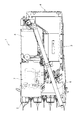
以下、本発明の実施の形態について、図面に基づいて説明する。図1〜図3において、1はコンバイン(作業用走行車)であって、該コンバイン1は、茎稈を刈り取る刈取部2と、茎稈から穀粒を脱穀して選別する脱穀部3と、選別した穀粒を貯留する穀粒タンク4と、穀粒タンク4内の穀粒を機外に搬出するオーガ5と、脱穀済の排稈を後処理する後処理部6と、オペレータが乗車する操縦部7と、クローラ式の走行部8とを備えて構成されている。
Hereinafter, embodiments of the present invention will be described with reference to the drawings. 1-3, 1 is a combine (working traveling vehicle), and the
操縦部7の下方には、エンジン9が搭載されている。図3に示すように、エンジン9は、燃料タンク10から供給される燃料で燃焼動作し、該燃焼動作に伴って出力されるエンジン動力がコンバイン1の各部に伝動される。燃料タンク10からエンジン9に至る燃料供給経路11には、燃料タンク10内の燃料を吸入してエンジン9に送る燃料ポンプ12と、燃料ポンプ12の上流側で燃料に含まれる水分を分離するセジメンタ13と、燃料ポンプ12の下流側で燃料を濾過する燃料フィルタ14と、が設けられている。
An engine 9 is mounted below the
セジメンタ13は、燃料から分離した水分を貯留する水貯留部13aと、該水貯留部13aに溜まった水分量を検出する水検出センサ13b(図6参照:水分量検出手段)と、を備える。本実施形態の水検出センサ13bは、水貯留部13aに溜まった水分量が水抜き作業を必要としないレベルのときはOFF状態を維持し、水貯留部13aに溜まった水分量が水抜き作業を必要とするレベルを超えるとON状態に切り換わるON/OFFスイッチであるが、水貯留部13aに溜まった水分量を多段階又は無段階に検出するものであってもよい。なお、燃料に含まれる水分は、主に燃料タンク10内に結露などで溜まった水分である。
The
図4に示すように、操縦部7には、オペレータが座る運転席15が設けられるとともに、その近傍には、マルチステアリングレバー16、主変速レバー17、副変速レバー18、液晶表示部19などが配置されている。
As shown in FIG. 4, a driver's
マルチステアリングレバー16は、運転席15の前方右側に配置されるジョイスティック型の操作レバーであり、その前後方向の操作に基いて刈取部2を昇降させる刈取昇降操作具と、その左右方向の操作に基いて機体の向きを変化させる操向操作具とに兼用される。
The
主変速レバー17及び副変速レバー18は、運転席15の左側方に配置されている。一方の主変速レバー17は、走行速度を無段変速する無段変速操作具と、前後進を切換える前後進切換操作具とを兼ねており、他方の副変速レバー18は、主変速レバー17による変速レンジを段階的に切換える有段変速操作具である。
The
液晶表示部19は、液晶パネル19aにタッチパネル19bを積層させたタッチパネル式の液晶ディスプレイであり、運転席15の前方左右中央部に配置されている。液晶表示部19は、後述する制御装置20(図6参照:表示制御部)に接続され、該制御装置20によって表示制御される。
The liquid
図5に示すように、制御装置20は、液晶表示部19に複数のタッチ操作ボタン21a〜21eを表示させるとともに、各タッチ操作ボタン21a〜21eのタッチ操作に応じて液晶表示部19の表示画面を切り換える。切換可能な表示画面には、各種の設定操作が可能な設定画面(図示せず)と、カメラ画像を表示するカメラ画像表示画面(図示せず)と、作業に必要な情報をシンプルに表示するシンプル表示画面(図示せず)と、作業に必要な情報を詳細に表示する通常表示画面A(図5の(b)参照)とが含まれている。
As shown in FIG. 5, the
図5の(b)に示すように、通常表示画面Aには、タッチ操作ボタン21a〜21eを表示するタッチ操作ボタン表示領域aと、機体に係る情報のうち、重要度が高い基本情報群を表示する基本情報表示領域bと、機体に係る情報のうち、基本情報群bよりも重要度が低い附属情報群を表示する附属情報表示領域cと、各種の警報を表示する警報表示領域dと、が含まれており、タッチ操作ボタン表示領域aは、通常表示画面Aの左端部に確保され、基本情報表示領域bは、タッチ操作ボタン表示領域aを除く通常表示画面Aの左半部に確保され、附属情報表示領域cは、タッチ操作ボタン表示領域aを除く通常表示画面Aの右半部に確保され、警報表示領域dは、通常表示画面Aの下端部に確保されている。ちなみに、本実施形態の基本情報群には、方向指示器情報、作業灯情報、エンジン回転情報、車速情報、燃料情報、エンジン負荷率情報、タンク籾量情報などが含まれ、附属情報群には、機体の傾き情報、チャフシーブ開度情報、唐箕風量情報などが含まれている。
As shown in FIG. 5B, the normal display screen A includes a touch operation button display area a that displays the
図5の(a)に示すように、制御装置20は、機体に異常が発生したとき、液晶表示部19に異常報知H1を表示させる。図5の(a)に示す異常報知H1は、セジメンタ13の水抜き作業を促すための報知(以下、適宜、セジメンタ報知ともいう)であり、前述した水検出センサ13bのONに応じて表示される。異常報知H1は、基本情報表示領域b及び附属情報表示領域cに重なるポップアップウインドウにより表示され、その表示領域内には、異常内容を示す「セジメンタ水センサ作動」と、対処方法を示す「セジメンタ内に水が溜まっています。セジメンタのドレンから水抜きをしてください」と、報知レベルを示す「注意」と、が含まれている。なお、本発明の異常報知は、セジメンタ13の水抜き作業を促す異常報知H1(H2、Hsを含む)に限らず、様々な異常を報知するものが含まれる。
As shown in FIG. 5A, the
図5の(a)、(b)に示すように、異常報知H1は、人為操作に応じた拡大表示と縮小表示との表示切換えが可能となっている。つまり、異常報知H1の表示当初は、図5の(a)に示す拡大表示で異常に対する注意を喚起するが、発生しても作業の継続が可能な異常である場合は、異常報知H1を縮小表示に切り換えることで、作業に必要な基本情報表示領域bや附属情報表示領域cの表示を優先させることができる。本実施形態では、図5の(a)に示す異常報知H1をタッチ操作(タップ操作)すると、図5の(b)に示すように、画面下部の警報表示領域dに縮小状態の異常報知Hsが表示される。縮小状態の異常報知Hsでは、異常に対する対処方法は表示されず、異常内容のみが表示される。また、縮小状態の異常報知Hsをタッチ操作すると、図5の(a)に示す拡大された異常報知H1に切り換わる。 As shown in FIGS. 5A and 5B, the abnormality notification H1 can be switched between an enlarged display and a reduced display according to a manual operation. That is, at the beginning of the display of the abnormality notification H1, attention is paid to the abnormality by the enlarged display shown in FIG. 5A. However, if the abnormality can be continued even if it occurs, the abnormality notification H1 is reduced. By switching to the display, priority can be given to the display of the basic information display area b and the auxiliary information display area c necessary for the work. In this embodiment, when the abnormality notification H1 shown in FIG. 5A is touched (tapped), as shown in FIG. 5B, the abnormality notification Hs in the reduced state is displayed in the alarm display area d at the bottom of the screen. Is displayed. In the reduced state abnormality notification Hs, the countermeasure method for the abnormality is not displayed, and only the abnormality content is displayed. Further, when the abnormality notification Hs in the reduced state is touch-operated, the enlarged abnormality notification H1 shown in FIG.
このような異常報知縮小表示機能によれば、作業に必要な基本情報表示領域bや附属情報表示領域cの表示を優先し、作業を継続することが可能であるが、異常が発生していることを忘れ、異常に対する対応を怠る虞がある。そこで、本発明の実施形態に係る制御装置20は、所定条件に基づいて、縮小表示状態の異常報知Hsを自動的に拡大表示させる。これにより、異常に対する確実且つ迅速な対応を促すことができる。なお、本実施形態では、拡大表示状態の異常報知H1を所定の人為操作に応じて縮小表示状態の異常報知Hsに切り換えるとともに、所定条件に基づいて自動的に拡大表示状態の異常報知H1(又はH2)で再表示させるが、拡大表示状態又は通常表示状態の異常報知を所定の人為操作に応じて非表示状態に切り換えるとともに、所定条件に基づいて自動的に異常報知を拡大表示状態又は通常表示状態で再表示させるようにしてもよい。
According to such an abnormality notification reduction display function, it is possible to prioritize the display of the basic information display area b and the auxiliary information display area c necessary for the work and continue the work, but an abnormality has occurred. There is a risk of forgetting things and neglecting to deal with abnormalities. Therefore, the
また、本実施形態の制御装置20は、所定条件に応じて、縮小表示状態の異常報知Hsを自動的に拡大表示させるとき、異常報知H2の表示内容を変更する。例えば、図5の(c)に示すように、異常対応の重要度や緊急性を示す文字列を「注意」から「警告」に変更するとともに、対処方法を示す文字列を「このまま使用するとエンジンが故障するおそれがあります。セジメンタの水を抜いてくだいさい」のように、セジメンタ13の水抜き作業を強く奨励する口調に変更する。これにより、異常に対する対応が後回しになったり、忘れてしまうことを抑制できる。
In addition, the
縮小表示状態の異常報知Hsを自動的に拡大表示させる所定条件は、機体操作又は機体動作とすることができる。例えば、エンジン9が再始動されたことを条件として縮小表示状態の異常報知Hsを自動的に拡大表示させる。このようにすると、脱穀刈取作業中を避けつつ、作業始めのタイミングで拡大状態の異常報知H2を表示させることができる。また、刈取クラッチ又は作業機(脱穀)クラッチが切り状態から入り状態に切り換わったことを条件として縮小表示状態の異常報知Hsを自動的に拡大表示させる。このようにすると、脱穀刈取作業中を避けつつ、刈始めのタイミングで拡大状態の異常報知H2を表示させることができる。また、刈取クラッチ又は作業機(脱穀)クラッチが入り状態から切り状態に切り換わったことを条件として縮小表示状態の異常報知Hsを自動的に拡大表示させてもよい。このようにすると、脱穀刈取作業中を避けつつ、刈終わりのタイミングで拡大状態の異常報知H2を表示させることができる。 The predetermined condition for automatically enlarging and displaying the abnormality notification Hs in the reduced display state can be an aircraft operation or an aircraft operation. For example, the abnormal notification Hs in the reduced display state is automatically enlarged and displayed on condition that the engine 9 is restarted. If it does in this way, abnormal notice H2 of an expansion state can be displayed at the timing of work start, avoiding during threshing and cutting work. Further, the abnormal notification Hs in the reduced display state is automatically enlarged and displayed on condition that the cutting clutch or the working machine (threshing) clutch is switched from the disengaged state to the engaged state. If it does in this way, the abnormal notice H2 of an expansion state can be displayed at the timing of the cutting start, avoiding the threshing and cutting work. Moreover, the abnormal notification Hs in the reduced display state may be automatically enlarged and displayed on condition that the reaping clutch or the work machine (threshing) clutch is switched from the engaged state to the disengaged state. If it does in this way, abnormal notice H2 of an expansion state can be displayed at the timing of the end of cutting, avoiding during the threshing and cutting work.
また、刈取部2が所定高さ以上(穀稈刈取作業では使用しない高さ)に上昇したことを条件として縮小表示状態の異常報知Hsを自動的に拡大表示させてもよい。このようにすると、脱穀刈取作業中を避けつつ、刈終わりのタイミングで拡大状態の異常報知H2を表示させることができる。また、刈取部2が所定高さ以下に下降したことを条件として縮小表示状態の異常報知Hsを自動的に拡大表示させてもよい。このようにすると、脱穀刈取作業中を避けつつ、刈始めのタイミングで拡大状態の異常報知H2を表示させることができる。
Moreover, the abnormal notification Hs in the reduced display state may be automatically enlarged and displayed on condition that the
また、マルチステアリングレバー16が所定角度以上左右に傾倒操作(旋回操作)されたことを条件として縮小表示状態の異常報知Hsを自動的に拡大表示させてもよい。このようにすると、脱穀刈取作業中を避けつつ、旋回始めのタイミングで拡大状態の異常報知H2を表示させることができる。
Further, the abnormal notification Hs in the reduced display state may be automatically enlarged and displayed on condition that the
また、オーガ5の排出クラッチが切り状態から入り状態、又は入り状態から切り状態に切り換わったことを条件として縮小表示状態の異常報知Hsを自動的に拡大表示させてもよい。このようにすると、脱穀刈取作業中を避けつつ、穀粒排出作業時に拡大状態の異常報知H2を表示させることができる。また、穀粒排出作業時は、通常表示画面Aのタンク籾量情報を確認するため、異常報知H2に気付き易いという利点がある。
Further, the abnormality notification Hs in the reduced display state may be automatically enlarged and displayed on condition that the discharge clutch of the
また、オーガ5が移動操作(昇降操作又は旋回操作)されたことを条件として縮小表示状態の異常報知Hsを自動的に拡大表示させてもよい。このようにすると、脱穀刈取作業中を避けつつ、穀粒排出作業時に拡大状態の異常報知H2を表示させることができる。
Further, the abnormal notification Hs in the reduced display state may be automatically enlarged and displayed on the condition that the
また、副変速レバー18が操作されたことを条件として縮小表示状態の異常報知Hsを自動的に拡大表示させてもよい。このようにすると、脱穀刈取作業中を避けつつ、作業走行から路上走行へ切り換える作業終わり、又は路上走行から作業走行へ切り換える作業始めのタイミングで拡大状態の異常報知H2を表示させることができる。
Further, the abnormal notification Hs in the reduced display state may be automatically enlarged and displayed on the condition that the
また、縮小表示状態の異常報知Hsを自動的に拡大表示させる所定条件は、収穫物の検出又は非検出であってもよい。例えば、刈取部2から脱穀部3に至る穀稈搬送経路に設けられる穀稈検出センサ38(図6参照)、又は脱穀部3の内部に設けられる選別物検出センサ39(図6参照)がOFFからON、又はONからOFFへ切り換わることを条件として縮小表示状態の異常報知Hsを自動的に拡大表示させてもよい。このようにすると、脱穀刈取作業中を避けつつ、作業始めや作業終わりのタイミングで拡大状態の異常報知H2を表示させることができる。
The predetermined condition for automatically enlarging and displaying the abnormality notification Hs in the reduced display state may be detection or non-detection of the harvest. For example, the cereal detection sensor 38 (see FIG. 6) provided in the cereal conveyance path from the reaping
また、縮小表示状態の異常報知Hsを自動的に拡大表示させる所定条件は、機体の位置であってもよい。例えば、3以上のGPS衛星から受信したGPS信号に基づいて機体の位置(緯度及び経度)を特定し、該特定した位置が圃場の進入位置又は退出位置であることを条件として縮小表示状態の異常報知Hsを自動的に拡大表示させてもよい。このようにすると、脱穀刈取作業中を避けつつ、作業始め又は作業終わりのタイミングで拡大状態の異常報知H2を表示させることができる。 The predetermined condition for automatically enlarging and displaying the abnormality notification Hs in the reduced display state may be the position of the aircraft. For example, the position of the aircraft (latitude and longitude) is specified based on GPS signals received from three or more GPS satellites, and the abnormal display state is reduced on the condition that the specified position is an entry position or an exit position of the field. The notification Hs may be automatically enlarged and displayed. If it does in this way, abnormal notice H2 of an expansion state can be displayed at the timing of work start or work end, avoiding during threshing and cutting work.
また、本実施形態の制御装置20は、機体の異常を検知し、最初の異常報知H1を液晶表示部19に表示する場合であっても、無条件に異常報知H1を表示するのではなく、車速が所定速度以下であることを条件として最初の異常報知H1を表示させるようになっている。このようにすると、走行中に異常報知H1が表示されることに起因する不具合が防止される。
Further, the
ところで、燃料に含まれる水分は、前述したように、主に結露などで燃料タンク10に溜まった水分であり、燃料タンク10に溜まった水分量が多い場合、セジメンタ13の水抜き報知である異常報知H1が頻繁に表示され、作業に支障を来す虞がある。なお、このような問題を解決するために、燃料タンク10に溜まった水分量を検出し、該検出水分量に基づいて、燃料タンク10の整備を促す報知を行うことが考えられるが、燃料タンク10に溜まった水分量を検出する検出手段は、セジメンタ13に溜まった水分量を検出する検出手段に比べて高価であり、大幅なコストアップとなる虞がある。
By the way, as described above, the moisture contained in the fuel is mainly accumulated in the
そこで、本発明の実施形態に係る制御装置20は、水検出センサ13bの検出水分量に基づいて、セジメンタ13の水抜き作業の要否を判断(以下、適宜、水溜り検出ともいう)するとともに、セジメンタ13の水抜き作業が実施されたか否かを判断(以下、適宜、水抜き検出ともいう)し、これらの判断に基づいて水抜き作業の発生頻度を特定する。そして、制御装置20は、特定した発生頻度が所定頻度よりも高いとき、燃料タンク10に多くの水分が溜まっていると判定し、燃料タンク10の整備(水抜き作業)を促す報知(以下、適宜、燃料タンク報知又は燃タン報知ともいう)を行う。
Therefore, the
水抜き作業の発生頻度は、例えば、セジメンタ13の水抜き作業が実施されたと判断した後、次回水抜き作業が必要と判断されるまでの計測時間に基づいて特定することができ、計測時間が所定時間よりも短いとき、水抜き作業の発生頻度が高いと判定することができる。また、水抜き作業の発生頻度は、水抜き作業の単位時間あたりの発生回数に基づいて特定するようにしてもよく、この場合には、水抜き作業の単位時間あたりの発生回数が所定回数よりも多いとき、水抜き作業の発生頻度が高いと判定することができる。なお、燃料タンク10の整備を促す異常報知は、図示を省略するが、セジメンタ13の水抜きを促す異常報知H1と同等のものであり、例えば、異常内容として「燃料タンク異常」を表示し、対処方法として「燃料タンク内に水が溜まっています。燃料タンクのドレンから水抜きをしてください」を表示する。
The frequency of occurrence of the water draining operation can be specified, for example, based on the measurement time until it is determined that the next water draining operation is necessary after it is determined that the drainage operation of the
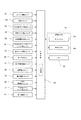
つぎに、上記のような液晶表示部19の表示動作を実現する制御装置20の入出力構成及び制御手順について、図6以降を参照して説明する。
Next, the input / output configuration and control procedure of the
図6に示すように、制御装置20は、CPUなどの制御プロセッサやRAM、ROMなどの記憶部を備えて構成されており、その入力側には、前述した水検出センサ13b、マルチステアリングレバー16(レバー角センサ)、主変速レバー17(レバー角センサ)、タッチパネル19b、穀稈検出センサ38及び選別物検出センサ39の他に、エンジン9の回転を検出するエンジン回転センサ31と、作業機クラッチの入り/切りを検出する作業機クラッチ検出センサ32と、刈取クラッチの入り/切りを検出する刈取クラッチ検出センサ33と、刈取部2の高さを検出する刈取部高さ検出センサ34と、排出クラッチの入り/切りを検出する排出クラッチセンサ35と、オーガ5の昇降操作や旋回操作を行うオーガリモコン36と、副変速レバー18の操作を検出する走行副変速検出センサ37と、GPS信号を受信するGPS40(受信モジュール)と、車速を検出する走行回転センサ41と、が接続される一方、制御装置20の出力側には、前述した液晶パネル19aの他に、異常報知に合わせて音を鳴らすためのブザー42が接続されている。
As shown in FIG. 6, the
そして、本実施形態の制御装置20は、ハードウエアとソフトウエアとの協働により実現される機能的な構成として、異常判断手段、異常報知表示手段(水抜き作業報知手段)、異常報知表示切換手段、異常報知再表示手段、表示内容変更手段、水抜き作業要否判断手段、水抜き作業実施判断手段及び燃料タンク整備報知手段を備えており、以下、制御装置20のメインルーチンである報知制御と、異常判断手段、異常報知表示手段(水抜き作業報知手段)、異常報知表示切換手段、異常報知再表示手段、表示内容変更手段、水抜き作業要否判断手段及び水抜き作業実施判断手段を実現するセジメンタ水抜き報知制御と、燃料タンク整備報知手段を実現する燃料タンク整備報知制御(以下、適宜、燃タン整備報知制御ともいう)の具体的な制御手順を説明する。
And the
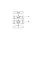
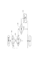
図7に示すように、報知制御では、サブルーチンであるセジメンタ水抜き報知制御(S1)及び燃料タンク整備報知制御(S2)を繰り返し実行する。 As shown in FIG. 7, in the notification control, subroutine water drain notification control (S1) and fuel tank maintenance notification control (S2), which are subroutines, are repeatedly executed.
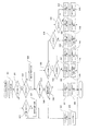
図8に示すように、セジメンタ水抜き報知制御では、後述するエンジン始動時処理(S21)を実行した後、今回実行時における水検出センサ13bのON/OFFと、前回実行時における水検出センサ13bのON/OFFとを判断する(S22、S23、S24)。
As shown in FIG. 8, in the drainage water alert control, after the engine start process (S21), which will be described later, is executed, the
ここで、今回実行時及び前回実行時において水検出センサ13bがいずれもOFFであると判断した場合は、セジメンタ報知フラグに「0」を記憶するとともに(S25)、液晶表示部19におけるセジメンタ報知の表示はなしとして(S26)、上位ルーチンへ復帰する。また、今回実行時において水検出センサ13bがOFFで、且つ前回実行時において水検出センサ13bがONであると判断した場合は、水抜き検出を履歴に記憶した後(S27)、ステップS25、S26を実行して上位ルーチンへ復帰する。
Here, when it is determined that both the
また、今回実行時及び前回実行時において水検出センサ13bがいずれもONであると判断した場合は、セジメンタ報知フラグの記憶値を判断し(S28)、また、今回実行時において水検出センサ13bがONで、且つ前回実行時において水検出センサ13bがOFFであると判断した場合は、水溜り検出を履歴に記憶した後(S29)、セジメンタ報知フラグの記憶値を判断する(S28)。
If it is determined that both the
ステップS28において、セジメンタ報知フラグの記憶値が「0」であると判断した場合は、機体走行停止状態(所定速度以下)であるか否かを判断し(S30)、該判断結果がYESである場合は、セジメンタ報知フラグに「1」を記憶するとともに(S31)、液晶表示部19にセジメンタ報知(注意:H1)を表示させた後(S32)、上位ルーチンへ復帰するが、ステップS30の判断結果がNOである場合は、ステップS25、S26を実行して上位ルーチンへ復帰する。
If it is determined in step S28 that the stored value of the sedimentor notification flag is “0”, it is determined whether or not the aircraft is in a stopped state (below a predetermined speed) (S30), and the determination result is YES. In this case, “1” is stored in the sedimentor notification flag (S31), and the liquid
一方、ステップS28において、セジメンタ報知フラグの記憶値が「0」以外であると判断した場合は、セジメンタ報知フラグの記憶値を再び判断し(S33)、該判断結果が「1」又は「3」である場合は、液晶表示部19のタッチ操作を判断する(S34)。ここで、タッチ操作無しと判断した場合は、セジメンタ報知フラグの記憶値を現状のまま維持するとともに(S35)、液晶表示部19に表示しているセジメンタ報知(注意又は警告:H1又はH2)も現状のまま維持して(S36)、上位ルーチンへ復帰する。一方、ステップS33において、タッチ操作有りと判断した場合は、セジメンタ報知フラグに「2」を記憶するとともに(S37)、液晶表示部19に表示しているセジメンタ報知(注意又は警告:H1又はH2)を縮小状態のセジメンタ報知(縮小:Hs)に切り換えた後(S38)、上位ルーチンへ復帰する。
On the other hand, if it is determined in step S28 that the stored value of the notification flag is other than “0”, the stored value of the notification flag is determined again (S33), and the determination result is “1” or “3”. If it is, a touch operation on the liquid
また、ステップS33において、セジメンタ報知フラグの記憶値が「2」であると判断した場合も、液晶表示部19のタッチ操作を判断する(S39)。ここで、タッチ操作有りと判断した場合は、セジメンタ報知フラグの記憶値を縮小前の記憶値に戻すとともに(S40)、液晶表示部19に表示している縮小状態のセジメンタ報知(縮小:Hs)を拡大状態のセジメンタ報知(注意又は警告:H1又はH2)に切り換えて(S41)、上位ルーチンへ復帰する。
Also, when it is determined in step S33 that the stored value of the segmenter notification flag is “2”, the touch operation of the liquid
一方、ステップS39において、タッチ操作無しと判断した場合は、前述した複数の所定条件のうち、条件を満たす所定条件の有無を判断し(S42)、該判断結果が無しの場合は、セジメンタ報知フラグの記憶値を現状のまま維持するとともに(S43)、液晶表示部19に表示している縮小状態のセジメンタ報知(縮小:Hs)も現状のまま維持して(S44)、上位ルーチンへ復帰する。一方、ステップS42において、有りと判断した場合は、セジメンタ報知フラグに「3」を記憶するとともに(S45)、液晶表示部19に表示している縮小状態のセジメンタ報知(縮小:Hs)を拡大状態のセジメンタ報知(警告:H2)に切り換えた後(S46)、上位ルーチンへ復帰する。
On the other hand, if it is determined in step S39 that there is no touch operation, the presence / absence of a predetermined condition that satisfies the condition among the plurality of predetermined conditions described above is determined (S42). Are maintained as they are (S43), and the reduced state segmenter notification (reduction: Hs) displayed on the liquid
図9に示すように、エンジン始動時処理では、今回実行時におけるエンジン駆動状態と、前回実行時におけるエンジン駆動状態とを判断する(S10、S11)。ここで、今回実行時においてエンジン9が駆動状態で、且つ前回実行時においてエンジン9が非駆動状態であると判断した場合は、セジメンタ報知フラグの記憶値を判断するが(S12)、それ以外の場合は、そのまま上位ルーチンへ復帰する。そして、ステップS12において、セジメンタ報知フラグの記憶値が「1」以外であると判断した場合は、そのまま上位ルーチンへ復帰するが、セジメンタ報知フラグの記憶値が「1」であると判断した場合は、セジメンタ報知フラグに「3」を記憶した後(S13)、上位ルーチンへ復帰する。 As shown in FIG. 9, in the engine start-up process, an engine drive state at the current execution time and an engine drive state at the previous execution time are determined (S10, S11). Here, when it is determined that the engine 9 is in the driving state at the time of the current execution and the engine 9 is in the non-driving state at the time of the previous execution, the stored value of the segmenter notification flag is determined (S12). In this case, the process returns to the upper routine as it is. In step S12, if it is determined that the stored value of the sedimentor notification flag is other than “1”, the process returns to the upper routine as it is, but if it is determined that the stored value of the sedimentor notification flag is “1”. Then, after storing “3” in the cementer notification flag (S13), the process returns to the upper routine.
図10に示すように、燃タン整備報知制御では、まず、今回実行時における水検出センサ13bのON/OFFを判断する(S50)。ここで、今回実行時において水検出センサ13bがOFFであると判断すると、燃タン報知フラグに「0」を記憶するとともに(S51)、液晶表示部19における燃タン報知の表示はなしとして(S52)、上位ルーチンへ復帰する。
As shown in FIG. 10, in the fuel tank maintenance notification control, first, it is determined whether the
一方、今回実行時において水検出センサ13bがONであると判断した場合は、燃タン報知フラグの記憶値を判断し(S53)、ここで、記憶値が「0」であると判断した場合は、前回実行時における水検出センサ13bのON/OFFを判断し(S54)、該判断結果がONの場合は、そのまま上位ルーチンへ復帰するが、OFFであると判断した場合は、セジメンタ13に対する水の混入が頻繁であるか否か、即ち水溜まり検出の頻度が高いか否かを判断する(S55)。本実施形態では、セジメンタ水抜き報知制御で記憶される水溜り検出及び水抜き検出の履歴を参照し、前回の水抜き検出から今回の水溜まり検出までの時間が所定時間よりも短い場合に水混入が頻繁であると判定する。そして、ステップS55の判断結果がYESの場合は、燃タン報知フラグに「1」を記憶するとともに(S56)、液晶表示部19に燃タン報知を表示させた後(S57)、上位ルーチンへ復帰するが、ステップS55の判断結果がNOである場合は、ステップS51、S52を実行して上位ルーチンへ復帰する。
On the other hand, if it is determined that the
一方、ステップS53において、記憶値が「0」以外であると判断した場合は、液晶表示部19のタッチ操作を判断する(S58)。ここで、タッチ操作無しと判断した場合は、燃タン報知フラグの記憶値を現状のまま維持するとともに(S59)、液晶表示部19に表示している燃タン報知も現状のまま維持して(S60)、上位ルーチンへ復帰する。一方、ステップS58において、タッチ操作有りと判断した場合は、燃タン報知フラグに「0」を記憶するとともに(S61)、液晶表示部19に表示している燃タン報知を非表示状態に切り換えた後(62)、上位ルーチンへ復帰する。
On the other hand, if it is determined in step S53 that the stored value is other than “0”, the touch operation of the liquid
叙述の如く構成された本実施形態によれば、液晶表示部19と、該液晶表示部19の表示を制御する制御装置20と、を備えるコンバイン1であって、制御装置20は、機体に異常が発生したとき、液晶表示部19に異常報知H1を表示させるとともに、オペレータの所定操作に応じて、異常報知H1を縮小表示状態(異常報知Hs)に切り換え、さらには、所定条件に基づいて、縮小表示状態の異常報知Hsを自動的に拡大表示状態の異常報知H2に切り換えるので、異常に対する確実且つ迅速な対応を促すことができる。
According to the present embodiment configured as described, the
また、縮小表示状態の異常報知Hsを自動的に拡大表示させるとき、異常報知H2の表示内容を変更するので、例えば、「注意→警告→危険」のように異常対応の重要度や緊急性を段階的に高くすることにより、異常に対する対応が後回しになったり、忘れてしまうことを抑制できる。 In addition, when the abnormality notification Hs in the reduced display state is automatically enlarged and displayed, the display content of the abnormality notification H2 is changed. For example, the importance or urgency of the abnormality response is changed to “Caution → Warning → Danger”. By making it higher step by step, it is possible to prevent the response to the abnormality from being delayed or forgotten.
また、所定条件は、機体操作又は機体動作であるため、作業中における異常報知H2の拡大表示を可及的に回避しつつ、刈り始め、刈り終わりなどの作業の切れ目に異常報知H2を拡大表示し、異常に対する対応を促すことができる。 Further, since the predetermined condition is airframe operation or airframe operation, the abnormality notification H2 is enlarged and displayed at the break of work such as the start of cutting and the end of cutting while avoiding the enlarged display of the abnormality notification H2 during work as much as possible. In addition, it is possible to encourage a response to the abnormality.
また、所定条件は、収穫物の検出又は非検出であるため、作業中における異常報知H2の拡大表示を可及的に回避しつつ、作業始め、作業終わりなどの作業の切れ目に異常報知H2を拡大表示し、異常に対する対応を促すことができる。 Further, since the predetermined condition is detection or non-detection of the harvested product, the abnormality notification H2 is displayed at a work break such as the start of the work or the end of the work while avoiding the enlarged display of the abnormality notification H2 during the work as much as possible. Enlarged display can be made to respond to the abnormality.
また、所定条件は、機体の位置であるため、作業中における異常報知H2の拡大表示を可及的に回避しつつ、圃場進入時、圃場退出時などに異常報知H2を拡大表示し、異常に対する対応を促すことができる。 Further, since the predetermined condition is the position of the machine body, the abnormality notification H2 is enlarged and displayed at the time of entering or leaving the field while avoiding the enlarged display of the abnormality notification H2 during work as much as possible. Response can be encouraged.
また、最初の異常報知H1は、機体に異常が発生し、且つ、車速が所定速度以下である場合に表示されるので、走行中に異常報知H1が表示されることに起因する不具合を防止できる。 In addition, since the first abnormality notification H1 is displayed when an abnormality occurs in the aircraft and the vehicle speed is equal to or lower than a predetermined speed, it is possible to prevent problems caused by displaying the abnormality notification H1 during traveling. .
1 コンバイン
2 刈取部
3 脱穀部
4 穀粒タンク
5 オーガ
7 操縦部
9 エンジン
10 燃料タンク
11 燃料供給経路
13 セジメンタ
13a 水貯留部
13b 水検出センサ
16 マルチステアリングレバー
17 主変速レバー
18 副変速レバー
19 液晶表示部
19a 液晶パネル
19b タッチパネル
20 制御装置
DESCRIPTION OF
Claims (6)
前記表示制御部は、
機体の異常を判断する異常判断手段と、
機体に異常が発生したとき、前記液晶表示部に拡大表示状態又は通常表示状態の異常報知を表示させる異常報知表示手段と、
オペレータの所定操作に応じて、前記異常報知を縮小表示状態又は非表示状態に切り換える異常報知表示切換手段と、
所定条件に基づいて、縮小表示状態又は非表示状態の前記異常報知を自動的に拡大表示状態又は通常表示状態で再表示させる異常報知再表示手段と、を備えることを特徴とする作業用走行車。 A working vehicle including a liquid crystal display unit and a display control unit that controls display of the liquid crystal display unit,
The display control unit
An abnormality determination means for determining an abnormality of the aircraft,
An abnormality notification display means for displaying an abnormality notification of an enlarged display state or a normal display state on the liquid crystal display unit when an abnormality occurs in the airframe;
An abnormality notification display switching means for switching the abnormality notification to a reduced display state or a non-display state according to a predetermined operation by an operator;
A working vehicle comprising: an abnormality notification redisplay unit that automatically redisplays the abnormality notification in the reduced display state or the non-display state in the enlarged display state or the normal display state based on a predetermined condition. .
Priority Applications (1)
| Application Number | Priority Date | Filing Date | Title |
|---|---|---|---|
| JP2017135444A JP2019017251A (en) | 2017-07-11 | 2017-07-11 | Work vehicle |
Applications Claiming Priority (1)
| Application Number | Priority Date | Filing Date | Title |
|---|---|---|---|
| JP2017135444A JP2019017251A (en) | 2017-07-11 | 2017-07-11 | Work vehicle |
Publications (1)
| Publication Number | Publication Date |
|---|---|
| JP2019017251A true JP2019017251A (en) | 2019-02-07 |
Family
ID=65352370
Family Applications (1)
| Application Number | Title | Priority Date | Filing Date |
|---|---|---|---|
| JP2017135444A Pending JP2019017251A (en) | 2017-07-11 | 2017-07-11 | Work vehicle |
Country Status (1)
| Country | Link |
|---|---|
| JP (1) | JP2019017251A (en) |
Cited By (1)
| Publication number | Priority date | Publication date | Assignee | Title |
|---|---|---|---|---|
| US20190293616A1 (en) * | 2018-03-22 | 2019-09-26 | Shimadzu Corporation | Gas chromatograph |
Citations (6)
| Publication number | Priority date | Publication date | Assignee | Title |
|---|---|---|---|---|
| JP2003180127A (en) * | 2001-12-14 | 2003-07-02 | Yanmar Agricult Equip Co Ltd | Displaying unit in implement |
| JP2005059779A (en) * | 2003-08-18 | 2005-03-10 | Yanmar Co Ltd | Control device for working vehicle |
| JP2006204245A (en) * | 2005-01-31 | 2006-08-10 | Iseki & Co Ltd | Equipment control input device of farm working vehicle |
| JP2010070078A (en) * | 2008-09-19 | 2010-04-02 | Nippon Seiki Co Ltd | Display device for vehicle |
| US20140189585A1 (en) * | 2012-12-28 | 2014-07-03 | Caterpillar Inc. | Information Display System for a Machine |
| JP2017100465A (en) * | 2015-11-30 | 2017-06-08 | 三菱マヒンドラ農機株式会社 | Work vehicle |
-
2017
- 2017-07-11 JP JP2017135444A patent/JP2019017251A/en active Pending
Patent Citations (6)
| Publication number | Priority date | Publication date | Assignee | Title |
|---|---|---|---|---|
| JP2003180127A (en) * | 2001-12-14 | 2003-07-02 | Yanmar Agricult Equip Co Ltd | Displaying unit in implement |
| JP2005059779A (en) * | 2003-08-18 | 2005-03-10 | Yanmar Co Ltd | Control device for working vehicle |
| JP2006204245A (en) * | 2005-01-31 | 2006-08-10 | Iseki & Co Ltd | Equipment control input device of farm working vehicle |
| JP2010070078A (en) * | 2008-09-19 | 2010-04-02 | Nippon Seiki Co Ltd | Display device for vehicle |
| US20140189585A1 (en) * | 2012-12-28 | 2014-07-03 | Caterpillar Inc. | Information Display System for a Machine |
| JP2017100465A (en) * | 2015-11-30 | 2017-06-08 | 三菱マヒンドラ農機株式会社 | Work vehicle |
Cited By (2)
| Publication number | Priority date | Publication date | Assignee | Title |
|---|---|---|---|---|
| US20190293616A1 (en) * | 2018-03-22 | 2019-09-26 | Shimadzu Corporation | Gas chromatograph |
| US10890568B2 (en) * | 2018-03-22 | 2021-01-12 | Shimadzu Corporation | Gas chromatograph |
Similar Documents
| Publication | Publication Date | Title |
|---|---|---|
| JP6564685B2 (en) | Working vehicle | |
| JP6571440B2 (en) | Working vehicle | |
| WO2016068185A1 (en) | Industrial running vehicle | |
| JP2019017251A (en) | Work vehicle | |
| KR102566904B1 (en) | Display apparatus included in work machine | |
| JP2017029107A (en) | Traveling work vehicle | |
| JP6936063B2 (en) | Working vehicle | |
| JP2007129939A (en) | Monitor display controller for combine harvester | |
| JP2007129939A5 (en) | ||
| JP7034732B2 (en) | A display device provided in the work equipment and a combine equipped with the display device. | |
| JP2009254280A (en) | Monitor display device for combine harvester | |
| JP2003009636A (en) | Combine harvester | |
| KR102557234B1 (en) | Display and combine with display | |
| JP2019170277A (en) | Combine | |
| JP6571439B2 (en) | Working vehicle | |
| JP6827374B2 (en) | A display device provided on the work equipment and a combine equipped with the display device. | |
| JP2003033110A (en) | Combine | |
| JP3353783B2 (en) | Combine monitoring device | |
| JPH1148802A (en) | Warning device in working vehicle | |
| JP2019004800A (en) | Display device provided to work vehicle | |
| KR102493704B1 (en) | Display apparatus included in work machine and combine having the display apparatus | |
| JP6619175B2 (en) | Working vehicle | |
| KR102530375B1 (en) | Display apparatus included in work machine | |
| JP6925182B2 (en) | Display device provided in the work machine | |
| JP2011188814A (en) | Monitor display device of combine harvester |
Legal Events
| Date | Code | Title | Description |
|---|---|---|---|
| A621 | Written request for application examination |
Free format text: JAPANESE INTERMEDIATE CODE: A621 Effective date: 20200331 |
|
| A977 | Report on retrieval |
Free format text: JAPANESE INTERMEDIATE CODE: A971007 Effective date: 20210312 |
|
| A131 | Notification of reasons for refusal |
Free format text: JAPANESE INTERMEDIATE CODE: A131 Effective date: 20210325 |
|
| A521 | Request for written amendment filed |
Free format text: JAPANESE INTERMEDIATE CODE: A523 Effective date: 20210519 |
|
| A131 | Notification of reasons for refusal |
Free format text: JAPANESE INTERMEDIATE CODE: A131 Effective date: 20210610 |
|
| A521 | Request for written amendment filed |
Free format text: JAPANESE INTERMEDIATE CODE: A523 Effective date: 20210730 |
|
| A02 | Decision of refusal |
Free format text: JAPANESE INTERMEDIATE CODE: A02 Effective date: 20210819 |