JP2019004315A - Terminal device, base station device, communication method, and integrated circuit - Google Patents
Terminal device, base station device, communication method, and integrated circuit Download PDFInfo
- Publication number
- JP2019004315A JP2019004315A JP2017117489A JP2017117489A JP2019004315A JP 2019004315 A JP2019004315 A JP 2019004315A JP 2017117489 A JP2017117489 A JP 2017117489A JP 2017117489 A JP2017117489 A JP 2017117489A JP 2019004315 A JP2019004315 A JP 2019004315A
- Authority
- JP
- Japan
- Prior art keywords
- random access
- information
- base station
- terminal device
- transmission
- Prior art date
- Legal status (The legal status is an assumption and is not a legal conclusion. Google has not performed a legal analysis and makes no representation as to the accuracy of the status listed.)
- Pending
Links
- 238000000034 method Methods 0.000 title claims abstract description 93
- 238000004891 communication Methods 0.000 title claims abstract description 50
- 230000005540 biological transmission Effects 0.000 claims abstract description 209
- 238000012544 monitoring process Methods 0.000 claims description 6
- 230000001413 cellular effect Effects 0.000 abstract description 3
- 238000012545 processing Methods 0.000 description 73
- 230000006870 function Effects 0.000 description 31
- 230000004044 response Effects 0.000 description 15
- 238000010586 diagram Methods 0.000 description 11
- 238000005516 engineering process Methods 0.000 description 11
- 230000011664 signaling Effects 0.000 description 11
- 239000013256 coordination polymer Substances 0.000 description 8
- 230000008569 process Effects 0.000 description 7
- 239000011159 matrix material Substances 0.000 description 6
- 125000004122 cyclic group Chemical group 0.000 description 4
- 230000007774 longterm Effects 0.000 description 4
- 230000001960 triggered effect Effects 0.000 description 4
- 239000000470 constituent Substances 0.000 description 3
- 238000005259 measurement Methods 0.000 description 3
- 238000012937 correction Methods 0.000 description 2
- 230000000694 effects Effects 0.000 description 2
- 238000013507 mapping Methods 0.000 description 2
- 230000010287 polarization Effects 0.000 description 2
- 238000011084 recovery Methods 0.000 description 2
- 239000004065 semiconductor Substances 0.000 description 2
- 101100274486 Mus musculus Cited2 gene Proteins 0.000 description 1
- 101100533725 Mus musculus Smr3a gene Proteins 0.000 description 1
- 241000700159 Rattus Species 0.000 description 1
- 101150096622 Smr2 gene Proteins 0.000 description 1
- 238000004378 air conditioning Methods 0.000 description 1
- 238000003491 array Methods 0.000 description 1
- 238000004140 cleaning Methods 0.000 description 1
- 238000013461 design Methods 0.000 description 1
- 238000011161 development Methods 0.000 description 1
- 230000007274 generation of a signal involved in cell-cell signaling Effects 0.000 description 1
- 230000006872 improvement Effects 0.000 description 1
- 230000003287 optical effect Effects 0.000 description 1
- 230000002093 peripheral effect Effects 0.000 description 1
- 230000009467 reduction Effects 0.000 description 1
- 238000010408 sweeping Methods 0.000 description 1
- 238000012546 transfer Methods 0.000 description 1
- 238000005406 washing Methods 0.000 description 1
Images


Classifications
-
- H—ELECTRICITY
- H04—ELECTRIC COMMUNICATION TECHNIQUE
- H04W—WIRELESS COMMUNICATION NETWORKS
- H04W74/00—Wireless channel access
- H04W74/08—Non-scheduled access, e.g. ALOHA
- H04W74/0833—Random access procedures, e.g. with 4-step access
-
- H—ELECTRICITY
- H04—ELECTRIC COMMUNICATION TECHNIQUE
- H04L—TRANSMISSION OF DIGITAL INFORMATION, e.g. TELEGRAPHIC COMMUNICATION
- H04L5/00—Arrangements affording multiple use of the transmission path
- H04L5/0001—Arrangements for dividing the transmission path
- H04L5/0003—Two-dimensional division
- H04L5/0005—Time-frequency
- H04L5/0007—Time-frequency the frequencies being orthogonal, e.g. OFDM(A), DMT
-
- H—ELECTRICITY
- H04—ELECTRIC COMMUNICATION TECHNIQUE
- H04L—TRANSMISSION OF DIGITAL INFORMATION, e.g. TELEGRAPHIC COMMUNICATION
- H04L5/00—Arrangements affording multiple use of the transmission path
- H04L5/003—Arrangements for allocating sub-channels of the transmission path
- H04L5/0048—Allocation of pilot signals, i.e. of signals known to the receiver
- H04L5/005—Allocation of pilot signals, i.e. of signals known to the receiver of common pilots, i.e. pilots destined for multiple users or terminals
-
- H—ELECTRICITY
- H04—ELECTRIC COMMUNICATION TECHNIQUE
- H04W—WIRELESS COMMUNICATION NETWORKS
- H04W16/00—Network planning, e.g. coverage or traffic planning tools; Network deployment, e.g. resource partitioning or cells structures
- H04W16/24—Cell structures
- H04W16/28—Cell structures using beam steering
-
- H—ELECTRICITY
- H04—ELECTRIC COMMUNICATION TECHNIQUE
- H04W—WIRELESS COMMUNICATION NETWORKS
- H04W72/00—Local resource management
- H04W72/20—Control channels or signalling for resource management
- H04W72/23—Control channels or signalling for resource management in the downlink direction of a wireless link, i.e. towards a terminal
-
- H—ELECTRICITY
- H04—ELECTRIC COMMUNICATION TECHNIQUE
- H04W—WIRELESS COMMUNICATION NETWORKS
- H04W74/00—Wireless channel access
- H04W74/002—Transmission of channel access control information
-
- H—ELECTRICITY
- H04—ELECTRIC COMMUNICATION TECHNIQUE
- H04W—WIRELESS COMMUNICATION NETWORKS
- H04W74/00—Wireless channel access
- H04W74/002—Transmission of channel access control information
- H04W74/006—Transmission of channel access control information in the downlink, i.e. towards the terminal
-
- H—ELECTRICITY
- H04—ELECTRIC COMMUNICATION TECHNIQUE
- H04L—TRANSMISSION OF DIGITAL INFORMATION, e.g. TELEGRAPHIC COMMUNICATION
- H04L5/00—Arrangements affording multiple use of the transmission path
- H04L5/003—Arrangements for allocating sub-channels of the transmission path
- H04L5/0048—Allocation of pilot signals, i.e. of signals known to the receiver
-
- H—ELECTRICITY
- H04—ELECTRIC COMMUNICATION TECHNIQUE
- H04L—TRANSMISSION OF DIGITAL INFORMATION, e.g. TELEGRAPHIC COMMUNICATION
- H04L5/00—Arrangements affording multiple use of the transmission path
- H04L5/14—Two-way operation using the same type of signal, i.e. duplex
- H04L5/1469—Two-way operation using the same type of signal, i.e. duplex using time-sharing
Landscapes
- Engineering & Computer Science (AREA)
- Signal Processing (AREA)
- Computer Networks & Wireless Communication (AREA)
- Mobile Radio Communication Systems (AREA)
- Reduction Or Emphasis Of Bandwidth Of Signals (AREA)
Abstract
Description
本発明は、端末装置、基地局装置、通信方法、および、集積回路に関する。 The present invention relates to a terminal device, a base station device, a communication method, and an integrated circuit.
現在、第5世代のセルラーシステムに向けた無線アクセス方式および無線ネットワーク技術として、第三世代パートナーシッププロジェクト(3GPP: The Third Generation Partnership Project)において、LTE(Long Term Evolution)−Advanced P
ro及びNR(New Radio technology)の技術検討及び規格策定が行われている(非特許文献1)。
Currently, LTE (Long Term Evolution)-Advanced P in the Third Generation Partnership Project (3GPP) as a wireless access method and wireless network technology for the fifth generation cellular system.
Technical examination and standard development of ro and NR (New Radio technology) are being performed (Non-Patent Document 1).
第5世代のセルラーシステムでは、高速・大容量伝送を実現するeMBB(enhanced Mobile BroadBand)、低遅延・高信頼通信を実現するURLLC(Ultra-Reliable and Low Latency Communication)、IoT(Internet of Things)などマシン型デバイスが多
数接続するmMTC(massive Machine Type Communication)の3つがサービスの想定シナリオとして要求されている。
In the fifth generation cellular system, eMBB (enhanced Mobile BroadBand) that realizes high-speed and large-capacity transmission, URLLC (Ultra-Reliable and Low Latency Communication) that realizes low latency and high-reliability communication, IoT (Internet of Things), etc. Three types of mass machine type communication (mMTC) in which a large number of machine type devices are connected are required as service scenario scenarios.
NRでは、高い周波数で多数のアンテナエレメントを用いてビームフォーミングゲインによりカバレッジを確保するマッシブMIMO(Multiple-Input Multiple-Output)の技術検討が行われている(非特許文献2、非特許文献3、非特許文献4)。
In NR, a technical study of massive multiple-input multiple-output (MIMO) that secures coverage by beam forming gain using a large number of antenna elements at high frequencies (Non-Patent
本発明は効率的に基地局装置と通信することができる端末装置、該端末装置と通信する基地局装置、該端末装置に用いられる通信方法、該基地局装置に用いられる通信方法を提供する。例えば、該端末装置、および、該基地局装置に用いられる通信方法は、効率的な通信、複雑性の低減、セル間、および/または、端末装置間の干渉を低減するための、上りリンク送信方法、変調方法、および/または、符号化方法を含んでもよい。 The present invention provides a terminal apparatus capable of efficiently communicating with a base station apparatus, a base station apparatus communicating with the terminal apparatus, a communication method used for the terminal apparatus, and a communication method used for the base station apparatus. For example, the communication method used for the terminal apparatus and the base station apparatus is an uplink transmission for efficient communication, reduction of complexity, inter-cell and / or interference between terminal apparatuses. Methods, modulation methods, and / or encoding methods may be included.
(1)本発明の態様は、以下のような手段を講じた。すなわち、本発明の第1の態様は、端末装置であって、基地局装置からランダムアクセス手順の開始を指示する指示情報を含む信号を受信する受信部と、前記指示情報に基づいて、前記1つまたは複数のランダムアクセスプリアンブルを送信する送信部と、を備え、前記送信部は、前記指示情報に含ま
れるSRSリソースに関する情報に基づいて前記ランダムアクセスプリアンブルの送信に用いるアンテナポートを決定する。
(1) The aspect of this invention took the following means. That is, a first aspect of the present invention is a terminal device, wherein a reception unit that receives a signal including instruction information for instructing start of a random access procedure from a base station apparatus; and A transmission unit that transmits one or a plurality of random access preambles, and the transmission unit determines an antenna port to be used for transmission of the random access preambles based on information on SRS resources included in the instruction information.
(2)本発明の第2の態様は、基地局装置であって、SRSリソースに関する情報を含むランダムアクセス手順の開始を指示する指示情報を生成する制御部と、端末装置に対して前記指示情報を含む信号を送信する送信部と、前記SRSリソースに関する情報に基づくランダムアクセスプリアンブルをモニタする受信部と、を備える。 (2) According to a second aspect of the present invention, there is provided a base station apparatus, a control unit that generates instruction information instructing start of a random access procedure including information on SRS resources, and the instruction information And a receiver that monitors a random access preamble based on information on the SRS resource.
(3)本発明の第3の態様は、端末装置に用いられる通信方法であって、地局装置からランダムアクセス手順の開始を指示する指示情報を含む信号を受信し、前記指示情報に基づいて、前記1つまたは複数のランダムアクセスプリアンブルを送信し、前記指示情報に含まれるSRSリソースに関する情報に基づいて前記ランダムアクセスプリアンブルの送信に用いるアンテナポートを決定する。 (3) A third aspect of the present invention is a communication method used for a terminal apparatus, which receives a signal including instruction information for instructing start of a random access procedure from a ground station apparatus, and based on the instruction information The one or more random access preambles are transmitted, and an antenna port to be used for transmission of the random access preamble is determined based on information on SRS resources included in the indication information.
(4)本発明の第4の態様は、基地局装置に用いられる通信方法であって、SRSリソースに関する情報を含むランダムアクセス手順の開始を指示する指示情報を生成し、端末装置に対して前記指示情報を含む信号を送信し、前記SRSリソースに関する情報に基づくランダムアクセスプリアンブルをモニタする。 (4) A fourth aspect of the present invention is a communication method used for a base station apparatus, which generates instruction information instructing start of a random access procedure including information on SRS resources, and A signal including instruction information is transmitted, and a random access preamble based on information on the SRS resource is monitored.
(5)本発明の第5の態様は、端末装置に実装される集積回路であって、基地局装置からランダムアクセス手順の開始を指示する指示情報を含む信号を受信する機能と、前記指示情報に基づいて、前記1つまたは複数のランダムアクセスプリアンブルを送信する機能と、前記指示情報に含まれるSRSリソースに関する情報に基づいて前記ランダムアクセスプリアンブルの送信に用いるアンテナポートを決定する機能と、を前記端末装置に発揮させる。 (5) According to a fifth aspect of the present invention, there is provided an integrated circuit mounted on a terminal device, the function of receiving a signal including instruction information for instructing start of a random access procedure from a base station apparatus, A function of transmitting the one or more random access preambles based on the information, and a function of determining an antenna port to be used for transmission of the random access preamble based on information on SRS resources included in the indication information, Make the terminal device perform.
(6)本発明の第6の態様は、基地局装置に実装される集積回路であって、SRSリソースに関する情報を含むランダムアクセス手順の開始を指示する指示情報を生成する機能と、端末装置に対して前記指示情報を含む信号を送信する機能と、前記SRSリソースに関する情報に基づくランダムアクセスプリアンブルをモニタする機能と、を前記基地局装置に発揮させる。 (6) A sixth aspect of the present invention is an integrated circuit implemented in a base station apparatus, and includes a function for generating instruction information for instructing start of a random access procedure including information on SRS resources, and a terminal apparatus On the other hand, the base station apparatus is caused to exhibit a function of transmitting a signal including the instruction information and a function of monitoring a random access preamble based on information on the SRS resource.
この発明によれば、端末装置および基地局装置は互いに効率的に通信および/または複雑性の低減をすることができる。 According to the present invention, the terminal device and the base station device can efficiently communicate with each other and / or reduce complexity.
以下、本発明の実施形態について説明する。 Hereinafter, embodiments of the present invention will be described.
LTE(およびLTE−Advanced Pro)とNRは、異なるRAT(Radio Access Technology)として定義されてもよい。NRは、LTEに含まれる技術として定
義されてもよい。本実施形態はNR、LTEおよび他のRATに適用されてよい。以下の説明では、LTEに関連する用語を用いて説明するが、他の用語を用いる他の技術においても適用されてもよい。
LTE (and LTE-Advanced Pro) and NR may be defined as different RAT (Radio Access Technology). NR may be defined as a technology included in LTE. This embodiment may be applied to NR, LTE and other RATs. In the following description, terms related to LTE will be used for explanation, but the present invention may be applied to other technologies using other terms.
図1は、本発明の実施形態に係る無線通信システムの概念図である。図1において、無線通信システムは、端末装置1A、端末装置1B、基地局装置3を具備する。端末装置1A、および、端末装置1Bを、端末装置1とも称する。
FIG. 1 is a conceptual diagram of a wireless communication system according to an embodiment of the present invention. In FIG. 1, the wireless communication system includes a
端末装置1は、移動局装置、ユーザ端末(UE: User Equipment)、通信端末、移動機、端末、MS(Mobile Station)などと称される場合もある。基地局装置3は、無線基地局装置、基地局、無線基地局、固定局、NB(Node B)、eNB(evolved Node B)、NR
NB(NR Node B)、gNB(next generation Node B)、アクセスポイント、BTS
(Base Transceiver Station)、BS(Base Station)などと称される場合もある。基地局装置3は、コアネットワーク装置を含んでもよい。また、基地局装置3は、1つまたは複数の送受信点4(transmission reception point:TRP)を具備してもよい。以下で説明する基地局装置3の機能/処理の少なくとも一部は、該基地局装置3が具備する各々の送受信点4における機能/処理であってもよい。基地局装置3は、基地局装置3によって制御される通信可能範囲(通信エリア)を1つまたは複数のセルとして端末装置1をサーブしてもよい。また、基地局装置3は、1つまたは複数の送受信点4によって制御される通信可能範囲(通信エリア)を1つまたは複数のセルとして端末装置1をサーブしてもよい。また、1つのセルを複数の部分領域(Beamed
area)にわけ、それぞれの部分領域において端末装置1をサーブしてもよい。ここで、部分領域は、ビームフォーミングで使用されるビームのインデックスあるいはプリコーディングのインデックスに基づいて識別されてもよい。
The
NB (NR Node B), gNB (next generation Node B), access point, BTS
(Base Transceiver Station), BS (Base Station), etc. may be called. The
area), the
基地局装置3がカバーする通信エリアは周波数毎にそれぞれ異なる広さ、異なる形状であっても良い。また、カバーするエリアが周波数毎に異なっていてもよい。また、基地局装置3の種別やセル半径の大きさが異なるセルが、同一の周波数または異なる周波数に混在して1つの通信システムを形成している無線ネットワークのことを、ヘテロジニアスネットワークと称する。
The communication area covered by the
基地局装置3から端末装置1への無線通信リンクを下りリンクと称する。端末装置1から基地局装置3への無線通信リンクを上りリンクと称する。端末装置1から他の端末装置1への無線通信リンクをサイドリンクと称する。
A wireless communication link from the
図1において、端末装置1と基地局装置3の間の無線通信および/または端末装置1と他の端末装置1の間の無線通信では、サイクリックプレフィックス(CP: Cyclic Prefix
)を含む直交周波数分割多重(OFDM: Orthogonal Frequency Division Multiplexing)、シングルキャリア周波数多重(SC-FDM: Single-Carrier Frequency Division Multiplexing)、離散フーリエ変換拡散OFDM(DFT-S-OFDM: Discrete Fourier Transform Spread OFDM)、マルチキャリア符号分割多重(MC-CDM: Multi-Carrier Code Division Multiplexing)が用いられてもよい。
In FIG. 1, in wireless communication between the
) Including Orthogonal Frequency Division Multiplexing (OFDM), Single-Carrier Frequency Division Multiplexing (SC-FDM), Discrete Fourier Transform Spread OFDM (DFT-S-OFDM) Multi-Carrier Code Division Multiplexing (MC-CDM) may be used.
また、図1において、端末装置1と基地局装置3の間の無線通信および/または端末装置1と他の端末装置1の間の無線通信では、ユニバーサルフィルタマルチキャリア(UFMC: Universal-Filtered Multi-Carrier)、フィルタOFDM(F-OFDM: Filtered OFDM)
、窓が乗算されたOFDM(Windowed OFDM)、フィルタバンクマルチキャリア(FBMC: Filter-Bank Multi-Carrier)が用いられてもよい。
In FIG. 1, in wireless communication between the
Further, OFDM with a window multiplied (Windowed OFDM) or Filter-Bank Multi-Carrier (FBMC) may be used.
なお、本実施形態ではOFDMを伝送方式としてOFDMシンボルで説明するが、上述の他の伝送方式の場合を用いた場合も本発明に含まれる。例えば、本実施形態におけるOFDMシンボルはSC−FDMシンボル(SC−FDMA(Single-Carrier Frequency Division Multiple Access)シンボルと称される場合もある)であってもよい。 In this embodiment, OFDM is described as an OFDM transmission system, but the case of using the other transmission systems described above is also included in the present invention. For example, the OFDM symbol in the present embodiment may be an SC-FDM symbol (sometimes referred to as an SC-FDMA (Single-Carrier Frequency Division Multiple Access) symbol).
また、図1において、端末装置1と基地局装置3の間の無線通信および/または端末装置1と他の端末装置1の間の無線通信では、CPを用いない、あるいはCPの代わりにゼロパディングをした上述の伝送方式が用いられてもよい。また、CPやゼロパディングは前方と後方の両方に付加されてもよい。
Further, in FIG. 1, in wireless communication between the
本実施形態では、端末装置1に対して1つまたは複数のサービングセルが設定される。設定された複数のサービングセルは、1つのプライマリーセル(Primary Cell、PCellと
も称される)と1つまたは複数のセカンダリーセル(Secondary Cell、SCellとも称され
る)とを含む。プライマリーセルは、初期コネクション確立(initial connection establishment)プロシージャが行なわれたサービングセル、コネクション再確立(connection
re-establishment)プロシージャを開始したサービングセル、または、ハンドオーバプ
ロシージャにおいてプライマリーセルと指示されたセルである。RRC(Radio Resource
Control)コネクションが確立された時点、または、後に、1つまたは複数のセカンダリーセルが設定されてもよい。ただし、設定された複数のサービングセルは、1つのプライマリーセカンダリーセル(Primary SCell、PSCellとも称される)を含んでもよい。プラ
イマリーセカンダリーセルは、端末装置1が設定された1つまたは複数のセカンダリーセルのうち、上りリンクにおいて制御情報を送信可能なセカンダリーセルであってもよい。また、端末装置1に対して、マスターセルグループ(Master Cell Group、MCGとも称される)とセカンダリーセルグループ(Secondary Cell Group、SCGとも称される)の2種類
のサービングセルのサブセットが設定されてもよい。マスターセルグループは1つのプライマリーセルと0個以上のセカンダリーセルで構成される。セカンダリーセルグループは1つのプライマリーセカンダリーセルと0個以上のセカンダリーセルで構成される。
In the present embodiment, one or more serving cells are set for the
The serving cell that has started the re-establishment) procedure or the cell designated as the primary cell in the handover procedure. RRC (Radio Resource
Control) One or more secondary cells may be set at or after the connection is established. However, the plurality of configured serving cells may include one primary secondary cell (also referred to as Primary SCell or PSCell). The primary secondary cell may be a secondary cell capable of transmitting control information in the uplink among one or a plurality of secondary cells in which the
本実施形態の無線通信システムは、TDD(Time Division Duplex)および/またはFDD(Frequency Division Duplex)が適用されてよい。複数のセルの全てに対してTD
D(Time Division Duplex)方式またはFDD(Frequency Division Duplex)方式が適
用されてもよい。また、TDD方式が適用されるセルとFDD方式が適用されるセルが集約されてもよい。
TDD (Time Division Duplex) and / or FDD (Frequency Division Duplex) may be applied to the wireless communication system of the present embodiment. TD for all of multiple cells
A D (Time Division Duplex) method or an FDD (Frequency Division Duplex) method may be applied. In addition, cells to which the TDD scheme is applied and cells to which the FDD scheme is applied may be aggregated.
下りリンクにおいて、サービングセルに対応するキャリアを下りリンクコンポーネントキャリア(あるいは下りリンクキャリア)と称する。上りリンクにおいて、サービングセルに対応するキャリアを上りリンクコンポーネントキャリア(あるいは上りリンクキャリア)と称する。サイドリンクにおいて、サービングセルに対応するキャリアをサイドリンクコンポーネントキャリア(あるいはサイドリンクキャリア)と称する。下りリンクコンポーネントキャリア、上りリンクコンポーネントキャリア、および/またはサイドリンクコンポーネントキャリアを総称してコンポーネントキャリア(あるいはキャリア)と称する。 In the downlink, a carrier corresponding to a serving cell is referred to as a downlink component carrier (or downlink carrier). In the uplink, a carrier corresponding to a serving cell is referred to as an uplink component carrier (or uplink carrier). In the side link, a carrier corresponding to the serving cell is referred to as a side link component carrier (or side link carrier). A downlink component carrier, an uplink component carrier, and / or a side link component carrier are collectively referred to as a component carrier (or carrier).
本実施形態の物理チャネルおよび物理信号について説明する。ただし、下りリンク物理チャネルおよび/または下りリンク物理信号を総称して、下りリンク信号と称してもよい。上りリンク物理チャネルおよび/または上りリンク物理信号を総称して、上りリンク信号と称してもよい。下りリンク物理チャネルおよび/または上りリンク物理チャネルを総称して、物理チャネルと称してもよい。下りリンク物理信号および/または上りリンク物理信号を総称して、物理信号と称してもよい。 The physical channel and physical signal of this embodiment will be described. However, the downlink physical channel and / or the downlink physical signal may be collectively referred to as a downlink signal. Uplink physical channels and / or uplink physical signals may be collectively referred to as uplink signals. The downlink physical channel and / or the uplink physical channel may be collectively referred to as a physical channel. The downlink physical signal and / or the uplink physical signal may be collectively referred to as a physical signal.
図1において、端末装置1と基地局装置3の下りリンク無線通信では、以下の下りリンク物理チャネルが用いられる。下りリンク物理チャネルは、上位層から出力された情報を送信するために使用される。
・NR−PBCH(New Radio Physical Broadcast CHannel)
・NR−PDCCH(New Radio Physical Downlink Control CHannel)
・NR−PDSCH(New Radio Physical Downlink Shared CHannel)
NR−PBCHは、端末装置1が必要とする重要なシステム情報(Essential
information)を含む重要情報ブロック(MIB:Master Information Block、EIB:Essential Information Block)を基地局装置3が報知するために用いられる。ここで、1つまたは複数の重要情報ブロックは、重要情報メッセージとして送信されてもよい。例えば、重要情報ブロックにはフレーム番号(SFN:System Frame Number)の一部あるいは全部を示す情報(例えば、複数のフレームで構成されるスーパーフレーム内における位置に関する情報)が含まれてもよい。例えば、無線フレーム(10ms)は、1msのサブフレームの10個で構成され、無線フレームは、フレーム番号で識別される。フレーム番号は、1024で0に戻る(Wrap around)。また、セル内の領域ごとに異なる重要
情報ブロックが送信される場合には領域を識別できる情報(例えば、領域を構成する下りリンク送信ビームの識別子情報)が含まれてもよい。ここで、下りリンク送信ビームの識別子情報は、下りリンク送信ビーム(プリコーディング)のインデックスを用いて示されてもよい。また、セル内の領域ごとに異なる重要情報ブロック(重要情報メッセージ)が送信される場合にはフレーム内の時間位置(例えば、当該重要情報ブロック(重要情報メッセージ)が含まれるサブフレーム番号)を識別できる情報が含まれてもよい。すなわち、異なる下りリンク送信ビームのインデックスが用いられた重要情報ブロック(重要情報メッセージ)の送信のそれぞれが行われるサブフレーム番号のそれぞれを決定するための情報が含まれてもよい。例えば、重要情報には、セルへの接続やモビリティのために必要な情報が含まれてもよい。
In FIG. 1, the following downlink physical channels are used in downlink wireless communication between the
・ NR-PBCH (New Radio Physical Broadcast CHannel)
・ NR-PDCCH (New Radio Physical Downlink Control CHannel)
・ NR-PDSCH (New Radio Physical Downlink Shared CHannel)
NR-PBCH is important system information (Essential
It is used for the
NR−PDCCHは、下りリンクの無線通信(基地局装置3から端末装置1への無線通信)において、下りリンク制御情報(Downlink Control Information: DCI)を送信する
ために用いられる。ここで、下りリンク制御情報の送信に対して、1つまたは複数のDCI(DCIフォーマットと称してもよい)が定義される。すなわち、下りリンク制御情報
に対するフィールドがDCIとして定義され、情報ビットへマップされる。
The NR-PDCCH is used to transmit downlink control information (Downlink Control Information: DCI) in downlink wireless communication (wireless communication from the
例えば、DCIとして、スケジューリングされたNR−PDSCHに対するHARQ−ACKを送信するタイミング(例えば、NR−PDSCHに含まれる最後のシンボルからHARQ−ACK送信までのシンボル数)示す情報を含むDCIが定義されてもよい。 For example, as DCI, DCI including information indicating timing for transmitting HARQ-ACK for a scheduled NR-PDSCH (for example, the number of symbols from the last symbol included in NR-PDSCH to HARQ-ACK transmission) is defined. Also good.
例えば、DCIとして、1つのセルにおける1つの下りリンクの無線通信NR−PDSCH(1つの下りリンクトランスポートブロックの送信)のスケジューリングのために用いられるDCIが定義されてもよい。 For example, DCI used for scheduling of one downlink radio communication NR-PDSCH (transmission of one downlink transport block) in one cell may be defined as DCI.
例えば、DCIとして、1つのセルにおける1つの上りリンクの無線通信NR−PUSCH(1つの上りリンクトランスポートブロックの送信)のスケジューリングのために用いられるDCIが定義されてもよい。 For example, DCI used for scheduling of one uplink radio communication NR-PUSCH (transmission of one uplink transport block) in one cell may be defined as DCI.
ここで、DCIには、NR−PDSCHあるいはNR−PUSCHのスケジューリングに関する情報が含まれる。ここで、下りリンクに対するDCIを、下りリンクグラント(downlink grant)、または、下りリンクアサインメント(downlink assignment)とも称
する。ここで、上りリンクに対するDCIを、上りリンクグラント(uplink grant)、または、上りリンクアサインメント(Uplink assignment)とも称する。
Here, DCI includes information related to scheduling of NR-PDSCH or NR-PUSCH. Here, the DCI for the downlink is also referred to as a downlink grant or a downlink assignment. Here, the DCI for the uplink is also referred to as an uplink grant or an uplink assignment.
NR−PDSCHは、媒介アクセス(MAC: Medium Access Control)からの下りリンクデータ(DL-SCH: Downlink Shared CHannel)の送信に用いられる。また、システム情報
(SI: System Information)やランダムアクセス応答(RAR: Random Access Response)
などの送信にも用いられる。
The NR-PDSCH is used for transmission of downlink data (DL-SCH: Downlink Shared CHannel) from a medium access control (MAC). Also, system information (SI) and random access response (RAR)
It is also used for transmission.
ここで、基地局装置3と端末装置1は、上位層(higher layer)において信号をやり取り(送受信)する。例えば、基地局装置3と端末装置1は、無線リソース制御(RRC: Radio Resource Control)層において、RRCシグナリング(RRC message: Radio Resource
Control message、RRC information: Radio Resource Control informationとも称され
る)を送受信してもよい。また、基地局装置3と端末装置1は、MAC(Medium Access Control)層において、MACコントロールエレメントを送受信してもよい。ここで、R
RCシグナリング、および/または、MACコントロールエレメントを、上位層の信号(higher layer signaling)とも称する。ここでの上位層は、物理層から見た上位層を意味するため、MAC層、RRC層、RLC層、PDCP層、NAS層などの一つまたは複数を含んでもよい。例えば、MAC層の処理において上位層とは、RRC層、RLC層、PDCP層、NAS層などの一つまたは複数を含んでもよい。
Here, the
Control message, RRC information: also called Radio Resource Control information) may be transmitted and received. Further, the
RC signaling and / or MAC control elements are also referred to as higher layer signaling. Here, the upper layer means an upper layer viewed from the physical layer, and may include one or more of a MAC layer, an RRC layer, an RLC layer, a PDCP layer, a NAS layer, and the like. For example, in the processing of the MAC layer, the upper layer may include one or a plurality of RRC layers, RLC layers, PDCP layers, NAS layers, and the like.
NR−PDSCHは、RRCシグナリング、および、MACコントロールエレメント(MAC CE: Medium Access Control Control Element)を送信するために用いられてもよい
。ここで、基地局装置3から送信されるRRCシグナリングは、セル内における複数の端末装置1に対して共通のシグナリングであってもよい。また、基地局装置3から送信されるRRCシグナリングは、ある端末装置1に対して専用のシグナリング(dedicated signalingとも称する)であってもよい。すなわち、端末装置固有(UEスペシフィック)な
情報は、ある端末装置1に対して専用のシグナリングを用いて送信されてもよい。
The NR-PDSCH may be used to transmit RRC signaling and a MAC control element (MAC CE). Here, the RRC signaling transmitted from the
図1において、下りリンクの無線通信では、以下の下りリンク物理信号が用いられる。ここで、下りリンク物理信号は、上位層から出力された情報を送信するために使用されないが、物理層によって使用される。
・同期信号(Synchronization signal: SS)
・参照信号(Reference Signal: RS)
同期信号は、端末装置1が下りリンクの周波数領域および時間領域の同期をとるために用いられる。同期信号は、プライマリ同期信号(PSS:Primary Synchronization Signal)およびセカンダリ同期信号(SSS)を含んでよい。また、同期信号は、端末装置1がセル識別子(セルID:Cell Identifier)を特定するために用いられてもよい。また
、同期信号は、下りリンクビームフォーミングにおいて基地局装置3が用いる下りリンク送信ビームおよび/または端末装置1が用いる下りリンク受信ビームの選択/識別/決定に用いられて良い。すなわち、同期信号は、基地局装置3によって下りリンク信号に対して適用された下りリンク送信ビームのインデックスを、端末装置1が選択/識別/決定するために用いられてもよい。ただし、NRにおいて用いられる同期信号、プライマリ同期信号およびセカンダリ同期信号をそれぞれNR−SS、NR−PSS、NR−SSSと称してもよい。
In FIG. 1, the following downlink physical signals are used in downlink wireless communication. Here, the downlink physical signal is not used for transmitting information output from the upper layer, but is used by the physical layer.
・ Synchronization signal (SS)
・ Reference signal (RS)
The synchronization signal is used for the
下りリンクの参照信号(以下、本実施形態では単に参照信号とも記載する)は、用途等に基づいて複数の参照信号に分類されてよい。例えば、参照信号には以下の参照信号の1つまたは複数が用いられてよい。 A downlink reference signal (hereinafter also simply referred to as a reference signal in the present embodiment) may be classified into a plurality of reference signals based on the application or the like. For example, one or more of the following reference signals may be used as the reference signal.
・DMRS(Demodulation Reference Signal)
・CSI−RS(Channel State Information Reference Signal)
・PTRS(Phase Tracking Reference Signal)
・MRS(Mobility Reference Signal)
DMRSは、受信した変調信号の復調時の伝搬路補償に用いられてよい。DMRSは、NR−PDSCHの復調用、NR−PDCCHの復調用、および/またはNR−PBCHの復調用のDMRSを総じてDMRSと称してもよいし、それぞれ個別に定義されてもよい。
DMRS (Demodulation Reference Signal)
・ CSI-RS (Channel State Information Reference Signal)
・ PTRS (Phase Tracking Reference Signal)
・ MRS (Mobility Reference Signal)
The DMRS may be used for propagation path compensation when demodulating the received modulated signal. DMRS may be collectively referred to as DMRS, or may be individually defined, for DMRS for NR-PDSCH demodulation, NR-PDCCH demodulation, and / or NR-PBCH demodulation.
CSI−RSは、チャネル状態測定に用いられてよい。PTRSは、端末の移動等により位相をトラックするために使用されてよい。MRSは、ハンドオーバのための複数の基地局装置からの受信品質を測定するために使用されてよい。 CSI-RS may be used for channel state measurement. PTRS may be used to track the phase, such as by movement of the terminal. MRS may be used to measure reception quality from multiple base station devices for handover.
また、参照信号には、位相雑音を補償するための参照信号が定義されてもよい。 In addition, a reference signal for compensating for phase noise may be defined in the reference signal.
ただし、上記複数の参照信号の少なくとも一部は、他の参照信号がその機能を有してもよい。 However, at least some of the plurality of reference signals may have the function of other reference signals.
また、上記複数の参照信号の少なくとも1つ、あるいはその他の参照信号が、セルに対して個別に設定されるセル固有参照信号(Cell−specific reference signal;CRS)、基地局装置3あるいは送受信点4が用いる送信ビーム毎のビーム固有参照信号(Beam−specific reference signal;BRS)、および/または、端末装置1に対して個別に設定される端末固有参照信号(UE−specific reference signal;URS)として定義されてもよい。
In addition, at least one of the plurality of reference signals, or other reference signals, a cell-specific reference signal (CRS), a
また、参照信号の少なくとも1つは、無線パラメータやサブキャリア間隔などのヌメロロジーやFFTの窓同期などができる程度の細かい同期(Fine synchronization)に用いられて良い。 In addition, at least one of the reference signals may be used for fine synchronization that allows numerology such as radio parameters and subcarrier intervals, FFT window synchronization, and the like.
また、参照信号の少なくとも1つは、無線リソース測定(RRM:Radio Resource Measurement)に用いられてよい。また、参照信号の少なくとも1つは、ビームマネジメントに用いられてよい。 In addition, at least one of the reference signals may be used for radio resource measurement (RRM). In addition, at least one of the reference signals may be used for beam management.
また、参照信号の少なくとも1つには、同期信号が用いられてもよい。 Further, a synchronization signal may be used as at least one of the reference signals.
図1において、端末装置1と基地局装置3の上りリンク無線通信(端末装置1から基地局装置3の無線通信)では、以下の上りリンク物理チャネルが用いられる。上りリンク物理チャネルは、上位層から出力された情報を送信するために使用される。
・NR−PUCCH(New Radio Physical Uplink Control CHannel)
・NR−PUSCH(New Radio Physical Uplink Shared CHannel)
・NR−PRACH(New Radio Physical Random Access CHannel)
NR−PUCCHは、上りリンク制御情報(Uplink Control Information: UCI)を送
信するために用いられる。ここで、上りリンク制御情報には、下りリンクのチャネルの状態を示すために用いられるチャネル状態情報(CSI: Channel State Information)が含まれてもよい。また、上りリンク制御情報には、UL−SCHリソースを要求するために用いられるスケジューリング要求(SR: Scheduling Request)が含まれてもよい。また、上りリンク制御情報には、HARQ−ACK(Hybrid Automatic Repeat request ACKnowledgement)が含まれてもよい。HARQ−ACKは、下りリンクデータ(Transport block, Medium Access Control Protocol Data Unit: MAC PDU, Downlink-Shared Channel: DL-SCH)に対するHARQ−ACKを示してもよい。
In FIG. 1, the following uplink physical channels are used in uplink wireless communication between the
・ NR-PUCCH (New Radio Physical Uplink Control CHannel)
・ NR-PUSCH (New Radio Physical Uplink Shared CHannel)
・ NR-PRACH (New Radio Physical Random Access CHannel)
The NR-PUCCH is used for transmitting uplink control information (UPCI). Here, the uplink control information may include channel state information (CSI: Channel State Information) used to indicate the state of the downlink channel. Further, the uplink control information may include a scheduling request (SR: Scheduling Request) used for requesting UL-SCH resources. Also, the uplink control information may include HARQ-ACK (Hybrid Automatic Repeat request ACKnowledgement). HARQ-ACK may indicate HARQ-ACK for downlink data (Transport block, Medium Access Control Protocol Data Unit: MAC PDU, Downlink-Shared Channel: DL-SCH).
NR−PUSCHは、媒介アクセス(MAC: Medium Access Control)からの上りリンクデータ(UL-SCH: Uplink Shared CHannel)の送信に用いられる。また、上りリンクデー
タと共にHARQ−ACKおよび/またはCSIを送信するために用いられてもよい。また、CSIのみ、または、HARQ−ACKおよびCSIのみを送信するために用いられてもよい。すなわち、UCIのみを送信するために用いられてもよい。
The NR-PUSCH is used for transmission of uplink data (UL-SCH: Uplink Shared CHannel) from a medium access control (MAC). Moreover, it may be used to transmit HARQ-ACK and / or CSI together with uplink data. Moreover, it may be used to transmit only CSI or only HARQ-ACK and CSI. That is, it may be used to transmit only UCI.
NR−PUSCHは、RRCシグナリング、および、MACコントロールエレメントを送信するために用いられてもよい。ここで、NR−PUSCHは、上りリンクに置いてUEの能力(UE Capability)の送信に用いられてもよい。 NR-PUSCH may be used to transmit RRC signaling and MAC control elements. Here, NR-PUSCH may be used for transmission of UE capability (UE Capability) in the uplink.
なお、NR−PDCCHとNR−PUCCHには同一の呼称(例えばNR−PCCH)および同一のチャネル定義が用いられてもよいし。NR−PDSCHとNR−PUSCHには同一の呼称(例えばNR−PSCH)および同一のチャネル定義が用いられてもよい。 In addition, the same name (for example, NR-PCCH) and the same channel definition may be used for NR-PDCCH and NR-PUCCH. The same name (for example, NR-PSCH) and the same channel definition may be used for NR-PDSCH and NR-PUSCH.
図1において、上りリンクの無線通信では、以下の上りリンク物理信号が用いられる。ここで、上りリンク物理信号は、上位層から出力された情報を送信するために使用されないが、物理層によって使用される。
・上りリンク参照信号(Uplink Reference Signal: UL RS)
本実施形態において、以下の2つのタイプの上りリンク参照信号が用いられる。
・DMRS(Demodulation Reference Signal)
・SRS(Sounding Reference Signal)
基地局装置3は、NR−PUSCHまたはNR−PUCCHの伝搬路補正を行なうためにDMRSを使用する。以下、NR−PUSCHとDMRSを共に送信することを、単にNR−PUSCHを送信すると称する。以下、NR−PUCCHとDMRSを共に送信することを、単にNR−PUCCHを送信すると称する。
In FIG. 1, the following uplink physical signals are used in uplink wireless communication. Here, the uplink physical signal is not used for transmitting information output from the higher layer, but is used by the physical layer.
・ Uplink Reference Signal (UL RS)
In this embodiment, the following two types of uplink reference signals are used.
DMRS (Demodulation Reference Signal)
・ SRS (Sounding Reference Signal)
The
基地局装置3は、上りリンクのチャネル状態を測定するためにSRSを使用する
NR−PRACHは、ランダムアクセスプリアンブルを送信するために用いられてもよい。NR−PRACHは、初期コネクション確立(initial connection establishment)プロシージャ、ハンドオーバプロシージャ、コネクション再確立(connection re−establishment)プロシージャ
、上りリンク送信に対する同期(タイミング調整)、およびNR−PUSCH(UL−SCH)リソースの要求を示すために用いられてもよい。
The
以下、サブフレームについて説明する。本実施形態ではサブフレームと称するが、リソースユニット、無線フレーム、時間区間、時間間隔などと称されてもよい。 Hereinafter, subframes will be described. Although referred to as a subframe in this embodiment, it may be referred to as a resource unit, a radio frame, a time interval, a time interval, or the like.
図2は、本発明の実施形態に係る下りリンクスロットの概略構成の一例を示す図である。無線フレームのそれぞれは、10ms長である。また、無線フレームのそれぞれは10個のサブフレームおよびX個のスロットから構成される。つまり、1サブフレームの長さは1msである。スロットのそれぞれは、サブキャリア間隔によって時間長が定義される。例えば、OFDMシンボルのサブキャリア間隔が15kHz、NCP(Normal Cyclic Prefix)の場合、X=7あるいはX=14であり、それぞれ0.5msおよび1msである。また、サブキャリア間隔が60kHzの場合は、X=7あるいはX=14であり、それぞれ0.125msおよび0.25msである。図2は、X=7の場合を一例として示している。なお、X=14の場合にも同様に拡張できる。また、上りリンクスロットも同様に定義され、下りリンクスロットと上りリンクスロットは別々に定義されてもよい。 FIG. 2 is a diagram illustrating an example of a schematic configuration of a downlink slot according to the embodiment of the present invention. Each radio frame is 10 ms long. Each radio frame is composed of 10 subframes and X slots. That is, the length of one subframe is 1 ms. Each slot has a time length defined by a subcarrier interval. For example, when the subcarrier interval of the OFDM symbol is 15 kHz and NCP (Normal Cyclic Prefix), X = 7 or X = 14, which is 0.5 ms and 1 ms, respectively. When the subcarrier interval is 60 kHz, X = 7 or X = 14, which are 0.125 ms and 0.25 ms, respectively. FIG. 2 shows an example where X = 7. Note that the same extension can be made when X = 14. Further, the uplink slot is defined in the same manner, and the downlink slot and the uplink slot may be defined separately.
スロットのそれぞれにおいて送信される信号または物理チャネルは、リソースグリッドによって表現されてよい。リソースグリッドは、複数のサブキャリアと複数のOFDMシンボルによって定義される。1つのスロットを構成するサブキャリアの数は、セルの下り
リンクおよび上りリンクの帯域幅にそれぞれ依存する。リソースグリッド内のエレメントのそれぞれをリソースエレメントと称する。リソースエレメントは、サブキャリアの番号とOFDMシンボルの番号とを用いて識別されてよい。
The signal or physical channel transmitted in each of the slots may be represented by a resource grid. The resource grid is defined by a plurality of subcarriers and a plurality of OFDM symbols. The number of subcarriers constituting one slot depends on the downlink and uplink bandwidths of the cell. Each element in the resource grid is referred to as a resource element. Resource elements may be identified using subcarrier numbers and OFDM symbol numbers.
リソースブロックは、ある物理下りリンクチャネル(PDSCHなど)あるいは上りリンクチャネル(PUSCHなど)のリソースエレメントのマッピングを表現するために用いられる。リソースブロックは、仮想リソースブロックと物理リソースブロックが定義される。ある物理上りリンクチャネルは、まず仮想リソースブロックにマップされる。その後、仮想リソースブロックは、物理リソースブロックにマップされる。スロットに含まれるOFDMシンボル数X=7で、NCPの場合には、1つの物理リソースブロックは、時間領域において7個の連続するOFDMシンボルと周波数領域において12個の連続するサブキャリアとから定義される。つまり、1つの物理リソースブロックは、(7×12)個のリソースエレメントから構成される。ECP(Extended CP)の場合、1つの物理リ
ソースブロックは、例えば、時間領域において6個の連続するOFDMシンボルと、周波数領域において12個の連続するサブキャリアとにより定義される。つまり、1つの物理リソースブロックは、(6×12)個のリソースエレメントから構成される。このとき、1つの物理リソースブロックは、時間領域において1つのスロットに対応し、周波数領域において180kHzに対応する。物理リソースブロックは、周波数領域において0から番号が付けられている。
The resource block is used to express mapping of resource elements of a certain physical downlink channel (PDSCH or the like) or uplink channel (PUSCH or the like). As resource blocks, virtual resource blocks and physical resource blocks are defined. A physical uplink channel is first mapped to a virtual resource block. Thereafter, the virtual resource block is mapped to the physical resource block. In the case of NCP in which the number of OFDM symbols included in a slot is X = 7, one physical resource block is defined by 7 consecutive OFDM symbols in the time domain and 12 consecutive subcarriers in the frequency domain. The That is, one physical resource block is composed of (7 × 12) resource elements. In the case of ECP (Extended CP), one physical resource block is defined by, for example, 6 consecutive OFDM symbols in the time domain and 12 consecutive subcarriers in the frequency domain. That is, one physical resource block is composed of (6 × 12) resource elements. At this time, one physical resource block corresponds to one slot in the time domain and corresponds to 180 kHz in the frequency domain. Physical resource blocks are numbered from 0 in the frequency domain.
次に、サブフレーム、スロット、ミニスロットについて説明する。図3は、サブフレーム、スロット、ミニスロットの時間領域における関係を示した図である。同図のように、3種類の時間ユニットが定義される。サブフレームは、サブキャリア間隔によらず1msであり、スロットに含まれるOFDMシンボル数は7または14であり、スロット長はサブキャリア間隔により異なる。ここで、サブキャリア間隔が15kHzの場合、1サブフレームには14OFDMシンボル含まれる。そのため、スロット長は、サブキャリア間隔をΔf(kHz)とすると、1スロットを構成するOFDMシンボル数が7の場合、スロット長は0.5/(Δf/15)msで定義されてよい。ここで、Δfはサブキャリア間隔(kHz)で定義されてよい。また、1スロットを構成するOFDMシンボル数が7の場合、スロット長は1/(Δf/15)msで定義されてよい。ここで、Δfはサブキャ
リア間隔(kHz)で定義されてよい。さらに、スロットに含まれるOFDMシンボル数をXとしたときに、スロット長はX/14/(Δf/15)msで定義されてもよい。
Next, subframes, slots, and minislots will be described. FIG. 3 is a diagram illustrating the relationship in the time domain between subframes, slots, and minislots. As shown in the figure, three types of time units are defined. The subframe is 1 ms regardless of the subcarrier interval, the number of OFDM symbols included in the slot is 7 or 14, and the slot length varies depending on the subcarrier interval. Here, when the subcarrier interval is 15 kHz, 14 OFDM symbols are included in one subframe. Therefore, the slot length may be defined as 0.5 / (Δf / 15) ms when the number of OFDM symbols constituting one slot is 7, where the subcarrier interval is Δf (kHz). Here, Δf may be defined by a subcarrier interval (kHz). When the number of OFDM symbols constituting one slot is 7, the slot length may be defined as 1 / (Δf / 15) ms. Here, Δf may be defined by a subcarrier interval (kHz). Further, when the number of OFDM symbols included in the slot is X, the slot length may be defined as X / 14 / (Δf / 15) ms.
ミニスロット(サブスロットと称されてもよい)は、スロットに含まれるOFDMシンボル数よりも少ないOFDMシンボルで構成される時間ユニットである。同図はミニスロットが2OFDMシンボルで構成される場合を一例として示している。ミニスロット内のOFDMシンボルは、スロットを構成するOFDMシンボルタイミングに一致してもよい。なお、スケジューリングの最小単位はスロットまたはミニスロットでもよい。 A mini-slot (which may be referred to as a sub-slot) is a time unit configured with fewer OFDM symbols than the number of OFDM symbols included in the slot. This figure shows an example in which a minislot is composed of 2 OFDM symbols. The OFDM symbols in the minislot may coincide with the OFDM symbol timing that constitutes the slot. The minimum scheduling unit may be a slot or a minislot.
図4に、スロットまたはサブフレームの一例を示している。ここでは、サブキャリア間隔15kHzにおいてスロット長が0.5msの場合を例として示している。同図において、Dは下りリンク、Uは上りリンクを示している。同図に示されるように、ある時間区間内(例えば、システムにおいて1つのUEに対して割り当てなければならない最小の時間区間)においては、
・下りリンクパート(デュレーション)
・ギャップ
・上りリンクパート(デュレーション)
のうち1つまたは複数を含んでよい。
FIG. 4 shows an example of a slot or a subframe. Here, a case where the slot length is 0.5 ms at a subcarrier interval of 15 kHz is shown as an example. In the figure, D indicates the downlink and U indicates the uplink. As shown in the figure, within a certain time interval (for example, the minimum time interval that must be allocated to one UE in the system),
・ Downlink part (duration)
・ Gap ・ Uplink part (duration)
One or more of them.
図4(a)は、ある時間区間(例えば、1UEに割当可能な時間リソースの最小単位、またはタイムユニットなどとも称されてよい。また、時間リソースの最小単位を複数束ねてタイムユニットと称されてもよい。)で、全て下りリンク送信に用いられている例であり、図4(b)は、最初の時間リソースで例えばNR−PDCCHを介して上りリンクのスケジューリングを行い、NR−PDCCHの処理遅延及び下りから上りの切り替え時間、送信信号の生成のためのギャップを介して上りリンク信号を送信する。図4(c)は、最初の時間リソースで下りリンクのNR−PDCCHおよび/または下りリンクのNR−PDSCHの送信に用いられ、処理遅延及び下りから上りの切り替え時間、送信信号の生成のためのギャップを介してNR−PUSCHまたはNR−PUCCHの送信に用いられる。ここで、一例としては、上りリンク信号はHARQ−ACKおよび/またはCSI、すなわちUCIの送信に用いられてよい。図4(d)は、最初の時間リソースでNR−PDCCHおよび/またはNR−PDSCHの送信に用いられ、処理遅延及び下りから上りの切り替え時間、送信信号の生成のためのギャップを介してNR−PUSCHおよび/またはNR−PUCCHの送信に用いられる。ここで、一例としては、上りリンク信号は上りリンクデータ、すなわちUL−SCHの送信に用いられてもよい。図4(e)は、全て上りリンク送信(NR−PUSCHまたはNR−PUCCH)に用いられている例である。 4A may be referred to as a certain time interval (for example, a minimum unit of time resources that can be allocated to one UE, or a time unit, etc. In addition, a plurality of minimum units of time resources are bundled to be referred to as a time unit. 4) is an example used for all downlink transmission, and FIG. 4 (b) performs uplink scheduling via the NR-PDCCH, for example, with the first time resource, and the NR-PDCCH An uplink signal is transmitted through a processing delay, a switching time from downlink to uplink, and a gap for generating a transmission signal. FIG. 4 (c) is used for transmission of downlink NR-PDCCH and / or downlink NR-PDSCH in the first time resource, for processing delay, downlink to uplink switching time, and transmission signal generation. It is used for transmission of NR-PUSCH or NR-PUCCH through a gap. Here, as an example, the uplink signal may be used for transmission of HARQ-ACK and / or CSI, that is, UCI. FIG. 4 (d) is used for transmission of NR-PDCCH and / or NR-PDSCH in the first time resource. NR− Used for transmission of PUSCH and / or NR-PUCCH. Here, as an example, the uplink signal may be used for transmission of uplink data, that is, UL-SCH. FIG.4 (e) is an example currently used for all uplink transmissions (NR-PUSCH or NR-PUCCH).
上述の下りリンクパート、上りリンクパートは、LTEと同様複数のOFDMシンボルで構成されてよい。 The downlink part and uplink part described above may be composed of a plurality of OFDM symbols as in LTE.
本発明の実施形態におけるビームフォーミング、ビームマネジメントおよび/またはビームスウィーピングについて説明する。 The beam forming, beam management and / or beam sweeping in the embodiment of the present invention will be described.
送信側(下りリンクの場合は基地局装置3であり、上りリンクの場合は端末装置1である)におけるビームフォーミングは、複数の送信アンテナエレメントの各々に対してアナログまたはデジタルで振幅・位相を制御することで任意の方向に高い送信アンテナゲインで信号を送信する方法であり、そのフィールドパターンを送信ビームと称する。また、受信側(下りリンクの場合は端末装置1、上りリンクの場合は基地局装置3である)におけるビームフォーミングは、複数の受信アンテナエレメントの各々に対してアナログまたはデジタルで振幅・位相を制御することで任意の方向に高い受信アンテナゲインで信号を受
信する方法であり、そのフィールドパターンを受信ビームと称する。ビームマネジメントは、送信ビームおよび/または受信ビームの指向性合わせ、ビーム利得を獲得するための基地局装置3および/または端末装置1の動作であってよい。
Beam forming on the transmission side (the
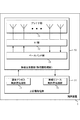
図5に、ビームフォーミングの一例を示す。複数のアンテナエレメントは1つの送信ユニット(TXRU: Transceiver unit)50に接続され、アンテナエレメント毎の位相シフタ51によって位相を制御し、アンテナエレメント52から送信することで送信信号に対して任意の方向にビームを向けることができる。典型的には、TXRU50がアンテナポートとして定義されてよく、端末装置1においてはアンテナポートのみが定義されてよい。位相シフタ51を制御することで任意の方向に指向性を向けることができるため、基地局装置3は端末装置1に対して利得の高いビームを用いて通信することができる。
FIG. 5 shows an example of beam forming. The plurality of antenna elements are connected to one transmission unit (TXRU: Transceiver unit) 50, the phase is controlled by a
ビームフォーミングは、ヴァーチャライゼーション、プリコーディング、ウェイトの乗算などと称されてもよい。また、単にビームフォーミングを用いて送信された信号そのものを送信ビームと呼んでもよい。 Beamforming may be referred to as virtualization, precoding, weight multiplication, and the like. Further, the signal itself transmitted simply using beam forming may be called a transmission beam.
本実施形態では、上りリンク送信のビームフォーミングで端末装置1が使用する送信ビームを上りリンク送信ビーム(UL Tx beam)と称し、上りリンク受信のビームフォーミングで基地局装置3が使用する受信ビームを上りリンク受信ビーム(UL Rx beam)と称する。ただし、上りリンク送信ビームを端末装置1における送信空間フィルタ設定と称し、上りリンク受信ビームを基地局装置3における受信空間フィルタ設定と称してもよい。また、下りリンク送信のビームフォーミングで基地局装置3が使用する送信ビームを下りリンク送信ビーム(DL Tx beam)と称し、下りリンク受信のビームフォーミングで端末装置1が使用する受信ビームを下りリンク受信ビーム(DL Rx beam)と称する。ただし、下りリンク送信ビームを基地局装置3における送信空間フィルタ設定と称し、下りリンク受信ビームを端末装置1における受信空間フィルタ設定と称してもよい。ただし、上りリンク送信ビームと上りリンク受信ビームを総じて上りリンクビーム、下りリンク送信ビームと下りリンク受信ビームを総じて下りリンクビームと称してもよい。ただし、上りリンクビームフォーミングのために端末装置1が行う処理を上りリンク送信ビーム処理、または上りリンクプリコーディングと称し、上りリンクビームフォーミングのために基地局装置3が行う処理を上りリンク受信ビーム処理と称してもよい。ただし、下りリンクビームフォーミングのために端末装置1が行う処理を下りリンク受信ビーム処理と称し、下りリンクビームフォーミングのために基地局装置3が行う処理を下りリンク送信ビーム処理または下りリンクプリコーディングと称してもよい。
In the present embodiment, a transmission beam used by the
ただし、1OFDMシンボルで基地局装置3が複数の下りリンク送信ビームを用いて信号を送信してもよい。例えば、基地局装置3のアンテナエレメントをサブアレーに分割して各サブアレーで異なる下りリンクビームフォーミングを行ってもよい。偏波アンテナを用いて各偏波で異なる下りリンクビームフォーミングを行ってもよい。同様に1OFDMシンボルで端末装置1が複数の上りリンク送信ビームを用いて信号を送信してもよい。
However, the
ただし、本実施形態では、基地局装置3および/または送受信点4が構成するセル内で当該基地局装置3が複数の下りリンク送信ビームを切り替えて使用する場合を説明するが、下りリンク送信ビーム毎に個別のセルが構成されてもよい。
However, in the present embodiment, a case will be described in which the
本実施形態に係るビームマネジメントには、下記の動作を含んでよい。
・ビーム選択(Beam selection)
・ビーム改善(Beam refinement)
・ビームリカバリ(Beam recovery)
例えば、ビーム選択は、基地局装置3と端末装置1の間の通信においてビームを選択す
る動作であってよい。また、ビーム改善は、さらに利得の高いビームの選択、あるいは端末装置1の移動によって最適な基地局装置3と端末装置1の間のビームの変更をする動作であってよい。ビームリカバリは、基地局装置3と端末装置1の間の通信において遮蔽物や人の通過などにより生じるブロッケージにより通信リンクの品質が低下した際にビームを再選択する動作であってよい。上記の動作は、上記の目的に限定されない。基地局装置3は、さまざまな状況でビームマネジメントを行うため、目的を限定しなくても、効果を発揮しうる。
The beam management according to the present embodiment may include the following operations.
・ Beam selection
・ Beam refinement
・ Beam recovery
For example, the beam selection may be an operation of selecting a beam in communication between the
例えば、端末装置1における基地局装置3の送信ビームを選択する際に参照信号(例えば、CSI−RS)を用いてもよいし、擬似同位置(QCL:Quasi Co-Location)想定
を用いてもよい。
For example, a reference signal (for example, CSI-RS) may be used when the transmission beam of the
もしあるアンテナポートにおけるあるシンボルが搬送されるチャネルの長区間特性(Long Term Property)が他方のアンテナポートにおけるあるシンボルが搬送されるチャネルから推論されうるなら、2つのアンテナポートはQCLであるといわれる。チャネルの長区間特性は、遅延スプレッド、ドップラースプレッド、ドップラーシフト、平均利得、及び平均遅延の1つまたは複数を含む。例えば、アンテナポート1とアンテナポート2が平均遅延に関してQCLである場合、アンテナポート1の受信タイミングからアンテナポート2の受信タイミングが推論されうることを意味する。
Two antenna ports are said to be QCL if the Long Term Property of the channel on which one symbol at one antenna port is carried can be inferred from the channel on which one symbol at the other antenna port is carried. . The long-term characteristics of the channel include one or more of delay spread, Doppler spread, Doppler shift, average gain, and average delay. For example, when
このQCLは、ビームマネジメントにも拡張されうる。そのために、空間に拡張したQCLが新たに定義されてもよい。例えば、空間のQCL想定におけるチャネルの長区間特性(Long term property)として、以下の一つまたは複数を、上記に加えてさらに含んでもよい。
・無線リンクあるいはチャネルにおける到来角(AoA(Angle of Arrival), ZoA(Zenith
angle of Arrival)など)および/またはその角度広がり(Angle Spread、例えばASA(Angle Spread of Arrival)やZSA(Zenith angle Spread of Arrival))
・無線リンクあるいはチャネルにおける送出角(AoD, ZoDなど)および/またはその角度広がり(Angle Spread、例えばASD(Angle Spread of Departure)やZSS(Zenith angle Spread of Departure))
・空間相関(Spatial Correlation)
この方法により、ビームマネジメントとして、空間のQCL想定と無線リソース(時間および/または周波数)によりビームマネジメントと等価な基地局装置3、端末装置1の動作が定義されてもよい。
This QCL can also be extended to beam management. Therefore, a QCL extended to a space may be newly defined. For example, in addition to the above, one or more of the following may be further included as the long term property of the channel in the spatial QCL assumption.
・ AoA (Angle of Arrival), ZoA (Zenith
angle of Arrival) and / or its angular spread (Angle Spread, eg ASA (Angle Spread of Arrival) or ZSA (Zenith angle Spread of Arrival))
-Transmission angle (AoD, ZoD, etc.) and / or its angular spread (Angle Spread, eg ASD (Angle Spread of Departure) or ZSS (Zenith angle Spread of Departure)) in a radio link or channel
・ Spatial Correlation
By this method, the operations of the
ただし、プリコーディングあるいは送信ビームの各々に対してアンテナポートが割り当てられてもよい。例えば、本実施形態に係る異なるプリコーディングを用いて送信される信号あるいは異なる送信ビームを用いて送信される信号は異なる一つまたは複数のアンテナポートで送信される信号として定義されてもよい。ただし、アンテナポートは、あるアンテナポートであるシンボルが送信されるチャネルを、同一のアンテナポートで別のシンボルが送信されるチャネルから推定できるものとして定義される。同一のアンテナポートとは、アンテナポートの番号(アンテナポートを識別するための番号)が、同一であることであってもよい。複数のアンテナポートでアンテナポートセットが構成されてもよい。同一のアンテナポートセットとは、アンテナポートセットの番号(アンテナポートセットを識別するための番号)が、同一であることであってもよい。異なる上りリンク送信ビームを適用して信号を送信するとは、異なるアンテナポートまたは複数のアンテナポートで構成される異なるアンテナポートセットで信号を送信することであってもよい。ビームインデックスはそれぞれOFDMシンボル番号、アンテナポート番号またはアンテナポートセット番号であってもよい。 However, an antenna port may be assigned to each of precoding or transmission beams. For example, a signal transmitted using different precoding or a signal transmitted using different transmission beams according to the present embodiment may be defined as a signal transmitted through different one or a plurality of antenna ports. However, an antenna port is defined as a channel through which a symbol that is a certain antenna port is transmitted can be estimated from a channel through which another symbol is transmitted through the same antenna port. The same antenna port may mean that the antenna port number (number for identifying the antenna port) is the same. An antenna port set may be configured by a plurality of antenna ports. The same antenna port set may be that the antenna port set number (the number for identifying the antenna port set) is the same. Transmitting a signal by applying different uplink transmission beams may be transmitting a signal using different antenna port sets or different antenna port sets including a plurality of antenna ports. Each beam index may be an OFDM symbol number, an antenna port number, or an antenna port set number.
トランスフォームプリコーディングには、レイヤマッピングで生成された、一つまたは複数のレイヤに対する複素変調シンボルが入力される。トランスフォームプリコーディングは、複素数シンボルのブロックを、一つのOFDMシンボルに対応するそれぞれのレイヤごとのセットに分割する処理であってもよい。OFDMが使われる場合には、トランスフォームプリコーディングでのDFT(Discrete Fourier Transform)の処理は必要ないかもしれない。プリコーディングは、トランスフォームプリコーダからの得られたベクターのブロックを入力として、リソースエレメントにマッピングするベクターのブロックを生成することであってもよい。空間多重の場合、リソースエレメントにマッピングするベクターのブロックを生成する際に、プリコーディングマトリックスの一つを適応してもよい。この処理を、デジタルビームフォーミングと呼んでもよい。また、プリコーディングは、アナログビームフォーミングとデジタルビームフォーミングを含んで定義されてもよいし、デジタルビームフォーイングとして定義されてもよい。プリコーディングされた信号にビームフォーミングが適用されるようにしてもよいし、ビームフォーミングが適用された信号にプリコーディングが適用されるようにしてもよい。ビームフォーミングは、アナログビームフォーミングを含んでデジタルビームフォーミングを含まなくてもよいし、デジタルビームフォーミングとアナログビームフォーミングの両方を含んでもよい。ビームフォーミングされた信号、プリコーディングされた信号、またはビームフォーミングおよびプリコーディングされた信号をビームと呼んでもよい。ビームのインデックスはプレコーディングマトリックスのインデックスでもよい。ビームのインデックスとプリコーディングマトリックスのインデックスが独立に定義されてもよい。ビームのインデックスで示されたビームにプリコーディングマトリックスのインデックスで示されるプリコーディングマトリックスを適用して信号を生成してもよい。プリコーディングマトリックスのインデックスで示されるプリコーディングマトリックスを適用した信号に、ビームのインデックスで示されたビームフォーミングを適用して信号を生成してもよい。デジタルビームフォーミングは、周波数方向のリソース(例えば、サブキャリアのセット)に異なるプリコーディングマトリックス適応することかもしれない。 In transform precoding, complex modulation symbols for one or a plurality of layers generated by layer mapping are input. Transform precoding may be a process of dividing a block of complex symbols into sets for each layer corresponding to one OFDM symbol. When OFDM is used, DFT (Discrete Fourier Transform) processing in transform precoding may not be necessary. Precoding may be to generate a vector block that maps to a resource element using the resulting vector block from the transform precoder as input. In the case of spatial multiplexing, one of the precoding matrices may be applied when generating a vector block that maps to resource elements. This processing may be called digital beam forming. Precoding may be defined including analog beam forming and digital beam forming, or may be defined as digital beam forming. Beamforming may be applied to a precoded signal, or precoding may be applied to a signal to which beamforming is applied. Beam forming may include analog beam forming and not include digital beam forming, or may include both digital beam forming and analog beam forming. A beamformed signal, a precoded signal, or a beamformed and precoded signal may be referred to as a beam. The beam index may be a precoding matrix index. The index of the beam and the index of the precoding matrix may be defined independently. A signal may be generated by applying the precoding matrix indicated by the index of the precoding matrix to the beam indicated by the index of the beam. The signal may be generated by applying the beamforming indicated by the beam index to the signal to which the precoding matrix indicated by the index of the precoding matrix is applied. Digital beamforming may apply different precoding matrices to resources in the frequency direction (eg, a set of subcarriers).
ただし、本実施形態では、所定の送信ビームおよび/または所定の受信ビームを用いて構成される無線リンクをビームペアリンクと称してもよい。例えば、下りリンクにおいて、異なる下りリンク送信ビームおよび/または異なる下りリンク受信ビームを用いて構成されるビームペアリンクを、異なる下りリンクビームペアリンクとしてもよい。例えば、上りリンクにおいて、異なる上りリンク送信ビームおよび/または異なる上りリンク受信ビームを用いて構成されるビームペアリンクを、異なる上りリンクビームペアリンクとしてもよい。例えば、端末装置1があるセルにおいて複数の下りリンク送信ビームおよび/または複数の下りリンク受信ビームを用いて下りリンク信号を受信しうる状態を、複数の下りリンクビームペアリンクを有する状態と称してもよい。例えば、端末装置1があるセルにおいて複数の上りリンク送信ビームおよび/または複数の上りリンク受信ビームを用いて上りリンク信号を送信しうる状態を、複数の上りリンクビームペアリンクを有する状態と称してもよい。
However, in the present embodiment, a radio link configured using a predetermined transmission beam and / or a predetermined reception beam may be referred to as a beam pair link. For example, in the downlink, beam pair links configured using different downlink transmission beams and / or different downlink reception beams may be different downlink beam pair links. For example, in the uplink, beam pair links configured using different uplink transmission beams and / or different uplink reception beams may be different uplink beam pair links. For example, a state in which a
本実施形態における下りリンクビームペアリンク(beam pair link)の概念について説明する。 The concept of the downlink beam pair link in this embodiment will be described.
図6は、端末装置1と基地局装置3がセル100において複数の下りリンクビームペアリンクを構成している場合を示している。第1の下りリンクビームペアリンクとして、基地局装置3から下りリンク送信ビームt1を用いて送信される下りリンク信号に対して端末装置1は下りリンク受信ビームr1を用いて受信する。第2の下りリンクビームペアリンクとして、基地局装置3から下りリンク送信ビームt2を用いて送信される下りリンク信号に対して端末装置1は下りリンク受信ビームr2を用いて受信する。第3の下りリンクビームペアリンクとして、基地局装置3から下りリンク送信ビームt3を用いて送信さ
れる下りリンク信号に対して端末装置1は下りリンク受信ビームr3を用いて受信する。この場合、端末装置1と基地局装置3の間には3つの下りリンクビームペアリンクが構成されており、3つの下りリンクビームペアリンクの全てあるいは一部で下りリンクの送受信が行われる。例えば、端末装置1は各下りリンクビームペアリンクにおいて参照信号による受信電力および/または受信品質の測定を行なう。
FIG. 6 shows a case where the
ただし、1つの下りリンク送信ビームに対して、複数の下りリンク受信ビームを用いて複数の下りリンクビームペアリンクが構成されてもよい。ただし、1つの下りリンク受信ビームに対して、複数の下りリンク送信ビームを用いて複数の下りリンクビームペアリンクが構成されてもよい。ただし、用いられる下りリンク受信ビームに関わらず、1つの下りリンク送信ビームに対して1つの下りリンクビームペアリンクが対応付けられてもよい。ただし、用いられる上りリンク送信ビームに関わらず、1つの上りリンク受信ビームに対して1つの上りリンクビームペアリンクが対応付けられてもよい。 However, a plurality of downlink beam pair links may be configured using a plurality of downlink reception beams for one downlink transmission beam. However, a plurality of downlink beam pair links may be configured using a plurality of downlink transmission beams for one downlink reception beam. However, one downlink beam pair link may be associated with one downlink transmission beam regardless of the downlink reception beam used. However, one uplink beam pair link may be associated with one uplink reception beam regardless of the uplink transmission beam used.
図7は、本実施形態に係る同期信号ブロック(SS(Synchronization Signal)ブロックとも称される)および同期信号バーストセット(SSバーストセットとも称される)の例を示す図である。図7は、周期的に送信される同期信号バーストセット内に2つの同期信号ブロックが含まれ、同期信号ブロックは、4OFDMシンボルで構成される例を示している。 FIG. 7 is a diagram illustrating an example of a synchronization signal block (also referred to as an SS (Synchronization Signal) block) and a synchronization signal burst set (also referred to as an SS burst set) according to the present embodiment. FIG. 7 shows an example in which two synchronization signal blocks are included in a synchronization signal burst set transmitted periodically, and the synchronization signal block is composed of 4 OFDM symbols.
ただし、1つまたは複数の同期信号ブロックが同期信号バースト(SSバーストと称される)を構成し、1つまたは複数の同期信号バーストが同期信号バーストセットを構成してもよい。 However, one or more synchronization signal blocks may constitute a synchronization signal burst (referred to as SS burst), and one or more synchronization signal bursts may constitute a synchronization signal burst set.
同期信号ブロックは、同期信号(例えばNR−PSS、NR−SSS)、および/またはNR−PBCHから構成される単位ブロックである。基地局装置3は同期信号バーストセット内の1つまたは複数の同期信号ブロックを用いて同期信号および/またはNR−PBCHを送信する場合に、同期信号ブロック毎に独立した下りリンク送信ビームを用いてもよい。
The synchronization signal block is a unit block composed of a synchronization signal (for example, NR-PSS, NR-SSS) and / or NR-PBCH. When the
図7において、1つの同期信号ブロックにはNR−PSS、NR−SSS、NR−PBCHが時間多重され、NR−PSSおよび/またはNR−SSSの帯域幅よりも広い帯域幅で送信されたNR−PBCHが2シンボル時間多重される例を示している。ただし、NR−PSS、NR−SSSおよび/またはNR−PBCHが時間領域で多重される順番は図7に示す例と異なってもよい。例えばNR−PBCHを2シンボルで送信する場合に2つのNR−PBCHシンボルの間にNR−SSSを送信するOFDMシンボルが存在してもよい。 In FIG. 7, NR-PSS, NR-SSS, and NR-PBCH are time-multiplexed in one synchronization signal block, and NR− transmitted with a bandwidth wider than the bandwidth of NR-PSS and / or NR-SSS. An example is shown in which PBCH is time-multiplexed by two symbols. However, the order in which NR-PSS, NR-SSS, and / or NR-PBCH are multiplexed in the time domain may be different from the example shown in FIG. For example, when NR-PBCH is transmitted with two symbols, there may be an OFDM symbol that transmits NR-SSS between two NR-PBCH symbols.
同期信号バーストセットは、周期的に送信されてよい。例えば、初期アクセスに使用されるための周期と、接続されている(ConnectedまたはRRC_Connected)端末装置のために設定する周期が定義されてもよい。また、接続されている(ConnectedまたはRRC_Connected)端末装置のために設定する周期はRRC層で設定されてよい。また、接続されている(ConnectedまたはRRC_Connected)端末のために設定する周期は潜在的に送信する可能性がある時間領域の無線リソースの周期であって、実際には基地局装置3が送信するかどうかを決めてもよい。また、初期アクセスに使用されるための周期は、仕様書などに予め定義されてよい。
The synchronization signal burst set may be transmitted periodically. For example, a cycle used for initial access and a cycle set for a connected terminal device (Connected or RRC_Connected) may be defined. Moreover, the period set for the connected terminal device (Connected or RRC_Connected) may be set in the RRC layer. In addition, the period set for the connected (Connected or RRC_Connected) terminal is a period of radio resources in the time domain that can potentially be transmitted, and is the
同期信号バーストセットは、システムフレーム番号(SFN:System Frame Number)
に基づいて決定されてよい。また、同期信号バーストセットの開始位置(バウンダリ)は、SFNと周期に基づいて決定されてよい。
The synchronization signal burst set is a system frame number (SFN).
May be determined based on Also, the start position (boundary) of the synchronization signal burst set may be determined based on the SFN and the period.
複数の同期信号バーストセットにおける各同期信号バーストセット内における相対的な時間が同じ同期信号ブロックは、同じ下りリンク送信ビームが適用されていると想定されてもよい。また、複数の同期信号バーストセットにおける各同期信号バーストセット内における相対的な時間が同じ同期信号ブロックにおけるアンテナポートは、平均遅延、ドップラーシフト、空間相関に関してQCLであると想定されてもよい。 It may be assumed that the same downlink transmission beam is applied to the synchronization signal blocks having the same relative time in each synchronization signal burst set in the plurality of synchronization signal burst sets. Further, the antenna port in the synchronization signal block having the same relative time in each synchronization signal burst set in the plurality of synchronization signal burst sets may be assumed to be QCL with respect to average delay, Doppler shift, and spatial correlation.
同期信号ブロック数は、例えば同期信号バースト、または同期信号バーストセット内、または同期信号ブロックの周期の中の同期信号ブロック数(個数)として定義されてよい。また、同期信号ブロック数は、同期信号バースト内、または同期信号バーストセット内、または同期信号ブロックの周期の中のセル選択のためのビームグループの数を示してもよい。ここで、ビームグループは、同期信号バースト内、または同期信号バーストセット内、または同期信号ブロックの周期の中に含まれる同期信号ブロックまたは異なるビームの数として定義されよい。 The number of synchronization signal blocks may be defined as, for example, the number (number) of synchronization signal blocks in a synchronization signal burst, or a synchronization signal burst set, or in the period of the synchronization signal block. Further, the number of synchronization signal blocks may indicate the number of beam groups for cell selection in a synchronization signal burst, a synchronization signal burst set, or a period of the synchronization signal block. Here, a beam group may be defined as the number of synchronization signal blocks or different beams included in a synchronization signal burst, or in a synchronization signal burst set, or in the period of a synchronization signal block.
本実施形態に係るSRSリソースの通知について説明する。 The notification of the SRS resource according to the present embodiment will be described.
基地局装置3は、端末装置1に対して、SRSリソースインディケータ(SRS Resource Indicator:SRI))を送信することによって、SRSを送信したリソースの1つまたは複数を通知する。1つまたは複数のSRSリソースは、少なくとも1つのアンテナポート、および/または1つの上りリンク送信ビーム(端末装置1の送信空間フィルタ設定あるいはプレコーダであってもよい)に関連付けられている。SRIの情報を受信した端末装置1は、該SRIに基づいて上りリンク送信に用いるアンテナポート、および/または上りリンク送信ビームを決定してもよい。
The
本実施形態のランダムアクセス手順(Random Access procedure)について説明する。 A random access procedure according to this embodiment will be described.
ランダムアクセス手順は、競合ベース(contention based)と非競合ベース(non−Contention based)の2つの手順に分類される。 Random access procedures are classified into two procedures: contention based and non-contention based.
端末装置1は、基地局装置3と接続(通信)していない状態からの初期アクセス時、および/または、基地局装置3と接続中であるが端末装置1に送信可能な上りリンクデータあるいは送信可能なサイドリンクデータが発生した場合のスケジューリングリクエスト時などにおいて競合ベースのランダムアクセス手順を行なう。ただし、ランダムアクセスの用途はこれらに限定されない。
The
端末装置1に送信可能な上りリンクデータが発生していることは、送信可能な上りリンクデータに対応するバッファステータスレポートがトリガーされていることを含んでもよい。端末装置1に送信可能な上りリンクデータが発生していることは、送信可能な上りリンクデータの発生に基づいてトリガーされたスケジューリングリクエストがペンディングされていることを含んでもよい。
The occurrence of uplink data that can be transmitted to the
端末装置1に送信可能なサイドリンクデータが発生していることは、送信可能なサイドリンクデータに対応するバッファステータスレポートがトリガーされていることを含んでもよい。端末装置1に送信可能なサイドリンクデータが発生していることは、送信可能なサイドリンクデータの発生に基づいてトリガーされたスケジューリングリクエストがペンディングされていることを含んでもよい。
The occurrence of side link data that can be transmitted to the
端末装置1は、基地局装置3からNR−PDCCHを受信し、該NR−PDCCHにランダムアクセス手順の開始を指示する情報が含まれていた場合に、非競合ベースのランダ
ムアクセス手順を行なってもよい。ただし、該ランダムアクセス手順の開始を指示する情報はNR−PDCCHオーダー、PDCCHオーダー、メッセージ0、Msg.0などと称されてもよい。非競合ベースのランダムアクセス手順は、基地局装置3からNR−PDCCHオーダーで指示されたランダムアクセスプリアンブルインデックスに対応するプリアンブルを使用してランダムアクセスを行う手順であり、基地局装置3と端末装置1とが接続中であるがハンドオーバや移動局装置の送信タイミングが有効でない場合に、迅速に端末装置1と基地局装置3との間の上りリンク同期をとるためなどに用いられる。ただし、ランダムアクセスの用途はこれらに限定されない。
When the
ただし、端末装置1は、NR−PDCCHオーダーで指示されたランダムアクセスプリアンブルインデックスが所定の値であった場合に、端末装置1が利用可能なプリアンブルのセットの中からランダムに1つを選択して送信する競合ベースのランダムアクセス手順を行なってもよい。
However, when the random access preamble index indicated by the NR-PDCCH order is a predetermined value, the
本実施形態の端末装置1は、ランダムアクセス手順を開始する(initiate)前に上位層を介してランダムアクセス設定情報を受信する。該ランダムアクセス設定情報には下記の情報または下記の情報を決定/設定するための情報が含まれてよい。
・ランダムアクセスプリアンブルの送信に利用可能な1つまたは複数の時間/周波数リソースのセット(PRACHリソースと称される場合もある)(例えば、利用可能なPRACHリソースのセット)
・1つまたは複数のランダムアクセスプリアンブルグループ
・利用可能な1つまたは複数のランダムアクセスプリアンブルあるいは前記複数のランダムアクセスプリアンブルグループにおいて利用可能な1つまたは複数のランダムアクセスプリアンブル
・ランダムアクセス応答のウィンドウサイズおよび衝突解消(コンテンションレゾリューション:Contention Resolution)タイマー(mac-ContentionResolutionTimer)
・パワーランピングステップ
・プリアンブル送信の最大送信回数
・プリアンブルの初期送信電力
・プリアンブルフォーマットに基づく電力オフセット
・パワーランピングの最大回数
ただし、ランダムアクセス設定情報は同期信号バーストセット内の1つの同期信号ブロックに関連付けられていてもよい。ただし、ランダムアクセス設定情報は設定された1つまたは複数のCSI−RSのうちの1つに関連付けられてもよい。ただし、ランダムアクセス設定情報は1つの下りリンク送信ビーム(あるいはビームインデックス)に関連付けられていてもよい。
The
A set of one or more time / frequency resources available for transmission of a random access preamble (sometimes referred to as PRACH resources) (eg, a set of available PRACH resources)
One or more random access preamble groups, one or more available random access preambles or one or more random access preambles available in the plurality of random access preamble groups, and the window size of the random access response and Conflict resolution (Contention Resolution) timer (mac-ContentionResolutionTimer)
-Power ramping step-Maximum number of transmissions of preamble transmission-Initial transmission power of preamble-Power offset based on preamble format-Maximum number of power ramping However, random access setting information is associated with one synchronization signal block in the synchronization signal burst set It may be done. However, the random access setting information may be associated with one of the set one or more CSI-RSs. However, the random access setting information may be associated with one downlink transmission beam (or beam index).
ただし、端末装置1は、下りリンク信号によって1つまたは複数のランダムアクセス設定情報を受信し、該1つまたは複数のランダムアクセス設定情報のそれぞれが同期信号ブロック(CSI−RSまたは下りリンク送信ビームであってもよい)に関連付けられていてもよい。端末装置1は、受信した1つまたは複数の同期信号ブロック(CSI−RSまたは下りリンク送信ビームであってもよい)のうちの1つを選択し、選択した同期信号ブロックに関連付けられたランダムアクセス設定情報を用いてランダムアクセス手順を行なってもよい。
However, the
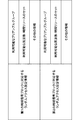
図8は、本実施形態に係るランダムアクセス設定情報の構成の例を示す図である。図8では、端末装置1が第1の同期信号ブロックに対応するランダムアクセス設定情報と第2の同期信号ブロックに対応するランダムアクセス設定情報を受信している。第1の同期信号ブロックに対応するランダムアクセス設定情報と第2の同期信号ブロックに対応するランダムアクセス設定情報のそれぞれがランダムアクセスに利用可能なプリアンブルグルー
プ、周波数・時間リソースのセット、および、その他の情報を含んでいる。
FIG. 8 is a diagram showing an example of the configuration of random access setting information according to the present embodiment. In FIG. 8, the
ただし、図8では、端末装置1が2つの同期信号ブロックに対応する2つのランダムアクセス設定情報を受信している場合を示しているが、端末装置1が3つ以上の同期信号ブロックに対応する3つ以上のランダムアクセス設定情報を受信してもよい。
However, although FIG. 8 shows a case where the
ただし、図8の例では、ランダムアクセス設定情報に含まれる各情報は同期信号ブロック毎に存在する場合を示しているが、ランダムアクセス設定情報に含まれる情報の一部が複数の同期信号ブロックで共通に設定されていてもよい。例えば、ランダムアクセス設定情報の一部は、同期信号ブロック、CSI−RSあるいは下りリンク送信ビーム(基地局装置3の送信フィルタ設定)毎に設定される情報であってもよく、その他がセル毎に設定される情報であってもよい。 However, the example of FIG. 8 shows a case where each piece of information included in the random access setting information exists for each synchronization signal block, but a part of the information included in the random access setting information is a plurality of synchronization signal blocks. It may be set in common. For example, a part of the random access setting information may be information set for each synchronization signal block, CSI-RS or downlink transmission beam (transmission filter setting of the base station apparatus 3), and others may be set for each cell. Information to be set may be used.
例えば、ランダムアクセス設定情報に含まれるランダムアクセスプリアンブルの送信に利用可能な1つまたは複数の時間/周波数リソースのセットは、同期信号ブロック、CSI−RS、および/または、下りリンク送信ビーム毎に設定されていてもよい。端末装置1は受信した同期信号ブロック、CSI−RS、および/または、下りリンク送信ビームに基づいてランダムアクセスプリアンブルの送信に利用可能な1つまたは複数の時間/周波数リソースのセットを選択してもよい。
For example, the set of one or more time / frequency resources that can be used for transmission of the random access preamble included in the random access setting information is set for each synchronization signal block, CSI-RS, and / or downlink transmission beam. May be. The
例えば、ランダムアクセス設定情報に含まれる1つまたは複数のランダムアクセスプリアンブルグループのそれぞれは、同期信号ブロック、CSI−RS、および/または、下りリンク送信ビーム毎に関連付けられていてもよい。端末装置1は受信した同期信号ブロック、CSI−RS、および/または、下りリンク送信ビームに基づいてのランダムアクセスプリアンブルグループを選択してもよい。
For example, each of the one or more random access preamble groups included in the random access setting information may be associated with each synchronization signal block, CSI-RS, and / or downlink transmission beam. The
ただし、図8の例では、1つのランダムアクセス設定情報が1つの同期信号ブロックに対応付けられている場合を示しているが、該1つのランダムアクセス設定情報は1つのインデックス(例えば、同期信号ブロックインデックス、CSI−RSインデックス、あるいは、下りリンク送信ビームインデックス等)に対応付けられていてもよい。 However, although the example of FIG. 8 shows a case where one random access setting information is associated with one synchronization signal block, the one random access setting information has one index (for example, a synchronization signal block). Index, CSI-RS index, downlink transmission beam index, etc.).
ただし、端末装置1は、それぞれ1つの下りリンク送信ビームを用いて送信された1つまたは複数の下りリンク信号を受信し、その中の1つの下りリンク信号に関連付けられたランダムアクセス設定情報を受信し、該受信したランダムアクセス設定情報に基づいてランダムアクセス手順を行なってもよい。端末装置1は、同期信号バーストセット内の1つまたは複数の同期信号ブロックを受信し、その中の1つの同期信号ブロックに関連付けられたランダムアクセス設定情報を受信し、該受信したランダムアクセス設定情報に基づいてランダムアクセス手順を行なってもよい。端末装置1は、1つまたは複数のCSI−RSを受信し、その中の1つのCSI−RSに関連付けられたランダムアクセス設定情報を受信し、該受信したランダムアクセス設定情報に基づいてランダムアクセス手順を行なってもよい。
However, each
1つまたは複数のランダムアクセス設定情報は、1つのランダムアクセスチャネル設定(RACH-Config)および/または1つの物理ランダムアクセスチャネル設定(PRACH-Config)で構成されてもよい。 The one or more random access configuration information may be configured with one random access channel configuration (RACH-Config) and / or one physical random access channel configuration (PRACH-Config).
ランダムアクセスチャネル設定の中に下りリンク送信ビーム毎のランダムアクセスに関するパラメータが含まれてもよい。 Parameters regarding random access for each downlink transmission beam may be included in the random access channel setting.
物理ランダムアクセスチャネル設定中に下りリンク送信ビーム毎の物理ランダムアクセ
スチャネルに関するパラメータ(PRACH設定のインデックス、ランダムアクセスプリアンブルの送信に利用可能な1つまたは複数の時間/周波数リソースなど)が含まれてもよい。
Parameters related to the physical random access channel for each downlink transmission beam (index of PRACH setting, one or more time / frequency resources available for transmission of the random access preamble, etc.) are included in the physical random access channel setting. Good.
1つのランダムアクセス設定情報は、1つの下りリンク送信ビームに対応するランダムアクセスに関するパラメータを示し、複数のランダムアクセス設定情報は、複数の下りリンク送信ビームに対応する複数のランダムアクセスに関するパラメータを示してもよい。 One random access setting information indicates a parameter related to random access corresponding to one downlink transmission beam, and a plurality of random access setting information indicates parameters related to a plurality of random access corresponding to a plurality of downlink transmission beams. Also good.
1つのランダムアクセス設定情報は、1つの下りリンク送信ビームに対応する物理ランダムアクセスに関するパラメータを示し、複数の下りリンク送信ビームに対応する複数のランダムアクセスに関するパラメータを示してもよい。 One random access setting information may indicate a parameter related to physical random access corresponding to one downlink transmission beam, and may indicate a parameter related to a plurality of random access corresponding to a plurality of downlink transmission beams.
対応するビームが選択されれば、ビームに対応するランダムアクセス設定情報(ビームに対応するランダムアクセスチャネル設定、ビームに対応する物理ランダムアクセスチャネル設定)が選択されるようにしてもよい。 If the corresponding beam is selected, random access setting information (random access channel setting corresponding to the beam, physical random access channel setting corresponding to the beam) corresponding to the beam may be selected.
ただし、端末装置1は、ランダムアクセスプリアンブルを送信する基地局装置3および/または送受信点4とは異なる基地局装置3および/または送受信点4から一つまたは複数のランダムアクセス設定情報を受信してもよい。例えば、端末装置1は第1の基地局装置3から受信したランダムアクセス設定情報の少なくとも1つに基づいて第2の基地局装置3へランダムアクセスプリアンブルを送信してもよい。
However, the
ただし、基地局装置3は、端末装置1が送信したランダムアクセスプリアンブルを受信することにより、該端末装置1へ下りリンク信号を送信する際に適用すべき下りリンク送信ビームを決定してもよい。端末装置1は、ある下りリンク送信ビームに関連付けられたランダムアクセス設定情報に示される時間/周波数リソースを用いてランダムアクセスプリアンブルを送信してもよい。基地局装置3は、端末装置1から受信したランダムアクセスプリアンブル、および/または、該ランダムアクセスプリアンブルを受信した時間/周波数リソースに基づいて、該端末装置1へ下りリンク信号を送信する際に適用すべき下りリンク送信ビームを決定してもよい。
However, the
本実施形態に係る端末装置1が、複数のランダムアクセス設定情報を受信し、該複数のランダムアクセス設定情報からランダムアクセス手順に使用する1つのランダムアクセス設定情報の選択する場合の選択ルールについて説明する。
A selection rule when the
端末装置1は、基地局装置3との間の伝搬路特性に基づいてランダムアクセス手順に使用するランダムアクセス設定情報を選択してもよい。端末装置1は、基地局装置3から受信した同期信号ブロックまたは下りリンク参照信号により測定した伝搬路特性に基づいてランダムアクセス手順に使用するランダムアクセス設定情報を選択してもよい。
The
端末装置1は、受信した複数のランダムアクセス設定情報から1つのランダムアクセス設定情報をランダムに選択してもよい。
The
端末装置1は、基地局装置3から受信した下りリンク信号に基づいて、受信した複数のランダムアクセス設定情報から1つのランダムアクセス設定情報を選択してもよい。ただし、該下りリンク信号は、ランダムアクセスプリアンブルの送信先である基地局装置3から受信したものであってもよいし、異なる基地局装置3から受信したものであってもよい。例えば、第1のセルを形成する第1の基地局装置3からの下りリンク信号に基づいて選択したランダムアクセス設定情報を第2のセルを形成する第2の基地局装置3とのランダムアクセス手順に用いてもよい。
The
ランダムアクセス設定情報に含まれる利用可能な1つまたは複数の周波数/時間リソースとして、それぞれランダムアクセスプリアンブルを送信可能なサブキャリアインデックス、リソースブロックインデックス、サブフレーム番号、システムフレーム番号、シンボル番号、および/または、プリアンブルのフォーマットが設定されてもよい。 As one or more available frequency / time resources included in the random access setting information, a subcarrier index, a resource block index, a subframe number, a system frame number, a symbol number, and / or a random access preamble can be transmitted. Alternatively, a preamble format may be set.
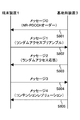
端末装置1が基地局装置3からNR−PDCCHオーダーを受信した場合のランダムアクセス手順は、図9に示すように、端末装置1と基地局装置3との間の複数のメッセージの送受信により実現される。
The random access procedure when the
<メッセージ0(S801)>
基地局装置3は、端末装置1に対してNR−PDCCHでNR−PDCCHオーダーを送信し、ランダムアクセス手順を行なうように指示する。
<Message 0 (S801)>
The
NR−PDCCHオーダーが示す情報には、プリアンブルインデックス情報、マスクインデックス情報、SRI(SRS Resource Indicator)情報、同期信号ブロック再選択指示情報(SS block Re-selection Indicator)、ランダムアクセス設定再選択指示情報(Random Access Configuration Re-selection Indicator)、および/または、CSI−RS
選択指示情報が含まれてもよい。
The information indicated by the NR-PDCCH order includes preamble index information, mask index information, SRI (SRS Resource Indicator) information, synchronization signal block reselection indication information (SS block Re-selection Indicator), random access setting reselection indication information ( Random Access Configuration Re-selection Indicator) and / or CSI-RS
Selection instruction information may be included.
プリアンブルインデックス情報は、ランダムアクセス設定情報に示される利用可能なランダムアクセスプリアンブルのプリアンブルインデックスのうち、1つまたは複数のプリアンブルインデックスを示す情報である。ただし、プリアンブルインデックス情報が所定の値である場合に、端末装置1は、利用可能な1つまたは複数のランダムアクセスプリアンブルから1つをランダムに選択してもよい。
The preamble index information is information indicating one or a plurality of preamble indexes among the preamble indexes of available random access preambles indicated in the random access setting information. However, when the preamble index information has a predetermined value, the
マスクインデックス情報は、時間領域および/または周波数領域でランダムアクセスプリアンブルの送信に利用可能なPRACHリソースのインデックスを示す情報である。ただし、マスクインデックス情報により示される時間リソースおよび/または周波数リソースは1つの特定のリソースであってもよいし、選択可能な複数のリソースを示すものであってもよいし、異なるインデックスが1つの特定リソースと選択可能な複数のリソースのそれぞれを示してもよい。 The mask index information is information indicating an index of a PRACH resource that can be used for transmission of a random access preamble in the time domain and / or the frequency domain. However, the time resource and / or frequency resource indicated by the mask index information may be one specific resource, may indicate a plurality of selectable resources, or a different index may be one specific resource. Each of a resource and a plurality of selectable resources may be indicated.
ただし、プリアンブルインデックス情報とマスクインデックス情報は1つのインデックス情報で示されてもよい。例えば、1つのインデックスで端末装置1がランダムアクセスプリアンブルの送信に利用可能なプリアンブル(系列、コードと称されてもよい)、時間リソースおよび周波数リソースの全てまたはその一部が示されてもよい。
However, the preamble index information and the mask index information may be indicated by one index information. For example, all or a part of a preamble (which may be referred to as a sequence or a code), a time resource, and a frequency resource that can be used by the
ただし、プリアンブルインデックス情報および/またはマスクインデックス情報は、同期信号ブロックごとに異なる値が設定されてもよい。例えば、端末装置1は、受信した1つまたは複数の同期信号ブロックの中から1つを選択し、選択した同期信号ブロックに関連付けられたプリアンブルインデックス情報および/またはマスクインデックス情報を用いてランダムアクセスプリアンブルを送信してもよい。
However, the preamble index information and / or the mask index information may be set to different values for each synchronization signal block. For example, the
ただし、プリアンブルインデックス情報および/またはマスクインデックス情報は、複数の同期信号ブロックで共通の値が設定されてもよい。例えば、端末装置1は、受信した1つまたは複数の同期信号ブロックの中から1つを選択し、選択した同期信号ブロックに関連付けられたランダムアクセス設定を選択し、利用可能なプリアンブルおよび/または時間/周波数リソースに対して、受信したプリアンブルインデックス情報および/またはマスクインデックス情報に対応するランダムアクセスプリアンブルを送信してもよい。
However, the preamble index information and / or mask index information may be set to a common value in a plurality of synchronization signal blocks. For example, the
SRI情報は、基地局装置3が設定している1つまたは複数のSRS送信用リソースのインデックスのうちの少なくとも一部を通知する情報である。ただし、SRI情報は、基地局装置3が設定している1つまたは複数のSRS送信用リソースに対応するビットマップ情報であってもよい。
The SRI information is information for notifying at least a part of one or a plurality of SRS transmission resource indexes set by the
端末装置1は、受信したSRI情報に基づいて、ランダムアクセスプリアンブルを送信するアンテナポートを決定してもよい。ただし、SRI情報が示すSRS送信用リソースが複数である場合に、端末装置1は複数のSRS送信用リソースに基づく複数のアンテナポートのそれぞれでランダムアクセスプリアンブルを送信してもよい。ただし、端末装置1は、SRI情報が示すSRS送信用リソースに関連付けられたアンテナポートを、ランダムアクセスプリアンブルの送信および再送に利用可能なアンテナポートとしてもよい。端末装置1は、SRI情報が示すSRS送信用リソースに関連付けられた上りリンク送信ビーム(送信空間フィルタ設定)でランダムアクセスプリアンブルを送信してもよい。ただし、NR−PDCCHオーダーでSRI情報を受信した端末装置1がランダムアクセスプリアンブルの送信に用いるアンテナポートは、SRI情報が示すSRS送信用リソースに関連付けられたアンテナポートとQCLであってもよい。
The
同期信号ブロック再選択指示情報は、NR−PDCCHオーダーを受信した端末装置1に対して、ランダムアクセス手順を行なうために用いる同期信号ブロックを再選択するか否かを指示する情報である。
The synchronization signal block reselection instruction information is information that instructs the
NR−PDCCHオーダーによって同期信号ブロック再選択指示情報が示されている場合、端末装置1は同期信号バーストセット内の1つまたは複数の同期信号ブロックをモニタし、選択した1つの同期信号ブロックに関連付けられたランダムアクセス設定を用いてランダムアクセスプリアンブルを送信してもよい。
When the synchronization signal block reselection instruction information is indicated by the NR-PDCCH order, the
ただし、同期信号ブロック再選択指示情報で示される情報は、NR−PDCCHオーダーで示されるその他の情報で示されてもよい。例えば、同期信号ブロック再選択指示情報で示される情報はプリアンブルインデックス情報に含まれてもよい。端末装置1は、NR−PDCCHオーダーで示されるプリアンブルインデックスが所定の値である場合に同期信号ブロックを再選択してもよい。
However, the information indicated by the synchronization signal block reselection instruction information may be indicated by other information indicated by the NR-PDCCH order. For example, information indicated by the synchronization signal block reselection instruction information may be included in the preamble index information. The
ランダムアクセス設定再選択指示情報は、NR−PDCCHオーダーを受信した端末装置1に対して、ランダムアクセス手順を行なうために用いるランダムアクセス設定情報を再選択するか否かを指示する情報である。NR−PDCCHオーダーでランダムアクセス設定再選択指示情報を受信した端末装置1は、下りリンク信号で受信した1つまたは複数のランダムアクセス設定情報の中から1つを選択し、選択したランダムアクセス設定情報に基づいてランダムアクセスプリアンブルの送信を行なってもよい。
The random access setting reselection instruction information is information that instructs the
ただし、ランダムアクセス設定再選択指示情報で示される情報は、NR−PDCCHオーダーで示されるその他の情報で示されてもよい。例えば、ランダムアクセス設定再選択指示情報で示される情報はプリアンブルインデックス情報に含まれてもよい。端末装置1は、NR−PDCCHオーダーで示されるプリアンブルインデックスが所定の値である場合にランダムアクセス設定情報を再選択してもよい。
However, the information indicated by the random access setting reselection instruction information may be indicated by other information indicated by the NR-PDCCH order. For example, information indicated by the random access setting reselection instruction information may be included in the preamble index information. The
CSI−RS選択指示情報は、NR−PDCCHオーダーを受信した端末装置1に対して、設定されている1つまたは複数のCSI−RSのうちランダムアクセス手順を行なうために用いる1つを選択することを指示する情報である。CSI−RS選択指示情報は、基地局装置3が端末装置1に対して設定している1つまたは複数のCSI−RSの少なく
とも一部を指定する情報であってもよい。
The CSI-RS selection instruction information selects one used for performing a random access procedure among one or a plurality of CSI-RSs set for the
NR−PDCCHオーダーによってCSI−RS選択指示情報が示されている場合、端末装置1は設定されている1つまたは複数のCSI−RSをモニタし、選択した1つのCSI−RSに関連付けられたランダムアクセス設定を用いてランダムアクセスプリアンブルを送信してもよい。
When the CSI-RS selection instruction information is indicated by the NR-PDCCH order, the
ただし、CSI−RS選択指示情報で示される情報は、NR−PDCCHオーダーで示されるその他の情報で示されてもよい。例えば、CSI−RS選択指示情報で示される情報はプリアンブルインデックス情報に含まれてもよい。端末装置1は、NR−PDCCHオーダーで示されるプリアンブルインデックスが所定の値である場合に設定されている1つまたは複数のCSI−RSをモニタし、選択した1つのCSI−RSに関連付けられたランダムアクセス設定を用いてランダムアクセスプリアンブルを送信してもよい。
However, the information indicated by the CSI-RS selection instruction information may be indicated by other information indicated by the NR-PDCCH order. For example, information indicated by CSI-RS selection instruction information may be included in the preamble index information. The
ただし、プリアンブルインデックス情報、SRI情報、同期信号ブロック再選択指示情報、ランダムアクセス設定再選択指示情報、および/または、CSI−RS選択指示情報に対して、1つの共通インデックス情報が用いられてもよい。例えば、共通インデックス情報が第1の値であった場合に、ランダムアクセス設定情報の再選択を行ない、共通イン
デックス情報が第2の値であった場合に1つまたは複数のCSI−RSをモニタしてもよい。
However, one common index information may be used for preamble index information, SRI information, synchronization signal block reselection instruction information, random access setting reselection instruction information, and / or CSI-RS selection instruction information. . For example, when the common index information is the first value, the random access setting information is reselected, and when the common index information is the second value, one or more CSI-RSs are monitored. May be.
<メッセージ1(S802)>
NR−PDCCHオーダーを受信した端末装置1は、基地局装置3に対して、物理ランダムアクセスチャネル(PRACH; Physical Random Access Channel)でランダムアクセス
のためのプリアンブルを送信する。この送信されるプリアンブルをランダムアクセスプリアンブル、メッセージ1またはMsg1と称してもよい。ランダムアクセスプリアンブルは、複数のシーケンスによって基地局装置3へ情報を通知するように構成される。例えば、64種類のシーケンスが用意されている場合、6ビットの情報を基地局装置3へ示すことができる。この情報は、ランダムアクセスプリアンブル識別子(Random Access preamble Identifier)として示される。プリアンブルシーケンスは、プリアンブルインデック
スを用いるプリアンブルシーケンスセットの中から選択される。
<Message 1 (S802)>
The
ただし、端末装置1は、NR−PDCCHオーダーによって1つのランダムアクセスプリアンブルを示すプリアンブルインデックスが示されている場合に示されたランダムアクセスプリアンブルを送信する。ただし、端末装置1は、NR−PDCCHオーダーによって所定の値を示すプリアンブルインデックスが示されている場合に利用可能なランダムアクセスプリアンブルからランダムに1つのランダムアクセスプリアンブルを選択してもよい。
However, the
ただし、NR−PDCCHオーダーによってマスクインデックスが示されている場合、端末装置1は示されたマスクインデックスに対応する周波数リソースおよび/または時間リソースを用いてランダムアクセスプリアンブルを送信する。
However, when the mask index is indicated by the NR-PDCCH order, the
ただし、NR−PDCCHオーダーによってSRI設定情報が示されている場合、端末装置1は、SRI設定情報に示されている1つまたは複数のSRS送信用リソースに対応するアンテナポートおよび/または上りリンク送信ビームを用いて1つまたは複数のランダムアクセスプリアンブルを送信する。
However, when the SRI setting information is indicated by the NR-PDCCH order, the
<メッセージ2(S803)>
ランダムアクセスプリアンブルを受信した基地局装置3は、端末装置1に送信を指示す
るための上りリンクグラントを含むランダムアクセス応答を生成し、生成したランダムアクセス応答を下りリンクのPSCHで端末装置1へ送信する。ランダムアクセス応答を、メッセージ2またはMsg2と称してもよい。また、基地局装置3は、受信したランダムアクセスプリアンブルから端末装置1と基地局装置3との間の送信タイミングのずれを算出し、該ずれを調整するための送信タイミング調整情報(Timing Advance Command)をメッセージ2に含める。また、基地局装置3は、受信したランダムアクセスプリアンブルに対応したランダムアクセスプリアンブル識別子をメッセージ2に含める。また、基地局装置3は、ランダムアクセスプリアンブルを送信した端末装置1宛てのランダムアクセス応答を示すためのRA−RNTI(ランダムアクセス応答識別情報:Random Access-Radio Network Temporary Identity)を、下りリンクのPCCHで送信する。RA−RNTIは、ランダムアクセスプリアンブルを送信した物理ランダムアクセスチャネルの周波数および時間の位置情報に応じて決定される。ここで、メッセージ2(下りリンクのPSCH)には、ランダムアクセスプリアンブルの送信に使用された上りリンク送信ビームのインデックスが含まれてもよい。また、下りリンクのPCCHおよび/またはメッセージ2(下りリンクのPSCH)を用いてメッセージ3の送信に使用される上りリンク送信ビームを決定するための情報が送信されてもよい。ここで、メッセージ3の送信に使用される上りリンク送信ビームを決定するための情報には、ランダムアクセスプリアンブルの送信に使用されたプリコーディングのインデックスからの差分(調整、補正)を示す情報が含まれてもよい。
<Message 2 (S803)>
The
<メッセージ3(S804)>
ランダムアクセスプリアンブルを送信した端末装置1は、該ランダムアクセスプリアンブル送信後の複数のサブフレーム期間(RA応答ウィンドウと称される)内で、RA−RNTIによって識別されるランダムアクセス応答に対する下りリンクのPCCHのモニタリングを行う。ランダムアクセスプリアンブルを送信した端末装置1は、該当するRA−RNTIを検出した場合に、下りリンクのPSCHに配置されたランダムアクセス応答の復号を行う。ランダムアクセス応答の復号に成功した端末装置1は、該ランダムアクセス応答に、送信したランダムアクセスプリアンブルに対応したランダムアクセスプリアンブル識別子が含まれるか否か確認する。ランダムアクセスプリアンブル識別子が含まれる場合、ランダムアクセス応答に示される送信タイミング調整情報を用いて同期のずれを補正する。また、端末装置1は受信したランダムアクセス応答に含まれる上りリンクグラントを用いて、バッファに保管されているデータを基地局装置3へ送信する。この時上りリンクグラントを用いて送信されるデータをメッセージ3またはMsg3と称する。
<Message 3 (S804)>
The
また、端末装置1は、復号に成功したランダムアクセス応答が一連のランダムアクセス手順において初めて受信に成功したものであった場合に、送信するメッセージ3に端末装置1を識別するための情報(C−RNTI)を含めて基地局装置3へ送信する。
In addition, when the random access response that has been successfully decoded is received for the first time in a series of random access procedures, the
<メッセージ4(S805)>
基地局装置3は、ランダムアクセス応答で端末装置1のメッセージ3に対して割り当てたリソースで上りリンク送信を受信すると、受信したメッセージ3に含まれるC−RNTI MAC CEを検出する。そして、該端末装置1と接続を確立する場合、基地局装置3は検出したC−RNTI宛てにPCCHを送信する。基地局装置3は、検出したC−RNTI宛てにPCCHを送信する場合、該PCCHに上りリンクグラントを含める。基地局装置3が送信するこれらのPCCHはメッセージ4、Msg4あるいはコンテンションレゾリューションメッセージと称される。
<Message 4 (S805)>
When the
メッセージ3を送信した端末装置1は、基地局装置3からのメッセージ4をモニタリングする期間を定めたコンテンションレゾリューションタイマーを開始し、タイマー内で基地局から送信される下りリンクのPCCHの受信を試みる。メッセージ3でC−RNTI
MAC CEを送信した端末装置1は、送信したC−RNTI宛てのPCCHを基地局装置3から受信し、かつ該PCCHに新規送信のための上りリンクグラントが含まれていた場合、他の端末装置1とのコンテンションレゾリューションに成功したものとみなし、コンテンションレゾリューションタイマーを停止し、ランダムアクセス手順を終了する。タイマー期間内で、自装置がメッセージ3で送信したC−RNTI宛てのPCCHの受信が確認できなかった場合は、コンテンションレゾリューションが成功しなかったとみなし、端末装置1は再度ランダムアクセスプリアンブルの送信を行い、ランダムアクセス手順を続行する。ただし、ランダムアクセスプリアンブルの送信を所定の回数繰り返し、コンテンションレゾリューションに成功しなかった場合には、ランダムアクセスに問題があると判定し、上位層にランダムアクセスプロブレムを指示する。例えば、上位層は、ランダムアクセスプロブレムに基づいてMACエンティティをリセットしてもよい。上位層によってMACエンティティのリセットを要求された場合、端末装置1は、ランダムアクセス手順をストップする。
The
When the
以上の5つのメッセージの送受信により、端末装置1は基地局装置3との同期をとり、基地局装置3に対する上りリンクデータ送信を行なうことができる。
By transmitting and receiving the above five messages, the
図10は、本実施形態に係る端末装置1のランダムアクセスプリアンブル送信処理の一例を示すフロー図である。
FIG. 10 is a flowchart showing an example of the random access preamble transmission process of the
端末装置1は、基地局装置3からランダムアクセス手順の開始を指示する情報(NR−PDCCHオーダー)を含む信号を受信する(S1001)。端末装置1は、受信したランダムアクセス手順の開始を指示する情報からSRSリソースに関する情報(例えば、SRI情報であってもよい)を検出する(S1002)。端末装置1は、検出したSRSリソースに関する情報に基づいてランダムアクセスプリアンブルの送信に使用するアンテナポートを決定する(S1003)。端末装置1は、決定したアンテナポートからランダムアクセスプリアンブルを送信する(S1004)。
The
図11は、本実施形態に係る基地局装置3のランダムアクセスプリアンブルの受信処理の一例を示すフロー図である。
FIG. 11 is a flowchart showing an example of a random access preamble reception process of the
基地局装置3は、SRSリソースに関する情報(例えばSRI情報であってもよい)を含むランダムアクセス手順の開始を指示する情報(NR−PDCCHオーダー)を生成する(S2001)。基地局装置3は、端末装置1に対して、生成したランダムアクセス手順の開始を指示する情報を含む信号を送信する(S2002)。基地局装置3は、送信したSRSリソースに関する情報に基づくランダムアクセスプリアンブルをモニタする(S2003)。
The
図12は、本実施形態に係る端末装置1のランダムアクセスプリアンブル送信処理の別の一例を示すフロー図である。
FIG. 12 is a flowchart showing another example of the random access preamble transmission process of the
端末装置1は、基地局装置3からランダムアクセス手順の開始を指示する指示情報(NR−PDCCHオーダー)を含む信号を受信する(S3001)。端末装置1は、受信した指示情報に基づいて1つまたは複数のランダムアクセス設定情報の中から1つを再選択するか否かを決定する(S3002)。端末装置1は、ランダムアクセス設定情報を再選択する場合に(S3003−YES)、受信した1つまたは複数のランダムアクセス設定情報の中から1つを選択し(S3004)、ステップS3005に移行する。端末装置1は、ランダムアクセス設定情報を再選択しない場合に(S3003−NO)、既に選択しているランダムアクセス設定情報を用いてステップS3005に移行する。端末装置1は、選択したランダムアクセス設定情報に基づいてランダムアクセスプリアンブルを送信す
る(S3005)。
The
図13は、本実施形態に係る基地局装置3のランダムアクセスプリアンブルの受信処理の別の一例を示すフロー図である。
FIG. 13 is a flowchart showing another example of the random access preamble reception process of the
基地局装置3は、端末装置1に複数のランダムアクセス設定情報の中から1つを再選択するか否かを指示する情報を含むランダムアクセス手順の開始を指示する情報(NR−PDCCHオーダー)を生成する(S4001)。基地局装置3は、端末装置1に対して、生成したランダムアクセス手順の開始を指示する情報を含む信号を送信する(S4002)。基地局装置3は、複数のランダムアクセス設定情報のそれぞれに関連付けられたランダムアクセスプリアンブルをモニタする(S4003)。
The
以下、本実施形態における装置の構成について説明する。 Hereinafter, the configuration of the apparatus according to the present embodiment will be described.
図14は、本実施形態の端末装置1の構成を示す概略ブロック図である。図示するように、端末装置1は、無線送受信部10、および、上位層処理部14を含んで構成される。無線送受信部10は、アンテナ部11、RF(Radio Frequency)部12、および、ベー
スバンド部13を含んで構成される。上位層処理部14は、媒体アクセス制御層処理部15、無線リソース制御層処理部16を含んで構成される。無線送受信部10を送信部、受信部、モニタ部、または、物理層処理部とも称する。上位層処理部14を測定部または制御部とも称する。
FIG. 14 is a schematic block diagram illustrating the configuration of the
上位層処理部14は、ユーザの操作等により生成された上りリンクデータ(トランスポートブロックと称されてもよい)を、無線送受信部10に出力する。上位層処理部14は、媒体アクセス制御(MAC: Medium Access Control)層、パケットデータ統合プロトコル(Packet Data Convergence Protocol: PDCP)層、無線リンク制御(Radio Link Control: RLC)層、無線リソース制御(Radio Resource Control: RRC)層の一部あるいはすべての処理を行なう。上位層処理部14は、受信したランダムアクセス手順の開始を指示する情報に基づいて、1つまたは複数の同期信号ブロックから1つを再選択するか否かを決定する機能を有してもよい。上位層処理部14は、受信したランダムアクセス手順の開始を指示する情報に基づいて、1つまたは複数のランダムアクセス設定情報から1つを再選択するか否かを決定する機能を有してもよい。
The upper
上位層処理部14が備える媒体アクセス制御層処理部15は、MACレイヤ(媒体アクセス制御層)の処理を行なう。媒体アクセス制御層処理部15は、無線リソース制御層処理部16によって管理されている各種設定情報/パラメータに基づいて、スケジューリング要求の伝送の制御を行う。
The medium access control layer processing unit 15 included in the upper
上位層処理部14が備える無線リソース制御層処理部16は、RRCレイヤ(無線リソース制御層)の処理を行なう。無線リソース制御層処理部16は、自装置の各種設定情報/パラメータの管理をする。無線リソース制御層処理部16は、基地局装置3から受信した上位層の信号に基づいて各種設定情報/パラメータをセットする。すなわち、無線リソース制御層処理部16は、基地局装置3から受信した各種設定情報/パラメータを示す情報に基づいて各種設定情報/パラメータをセットする。
The radio resource control layer processing unit 16 included in the upper
無線送受信部10は、変調、復調、符号化、復号化などの物理層の処理を行う。無線送受信部10は、基地局装置3から受信した信号を、分離、復調、復号し、復号した情報を上位層処理部14に出力する。無線送受信部10は、データを変調、符号化することによって送信信号を生成し、基地局装置3に送信する。無線送受信部10は、あるセルにおける1つまたは複数の同期信号ブロックを受信する機能を有してもよい。無線送受信部10
は、基地局装置3からランダムアクセス手順の開始を指示する指示情報を含む信号を受信する機能を有してもよい。無線送受信部10は、複数の参照信号を受信する機能を有してもよい。無線送受信部10は、基地局装置3から受信したSRSリソースに関する情報に基づいてランダムアクセスプリアンブルの送信に用いるアンテナポート決定する機能を有してもよい。
The wireless transmission /
May have a function of receiving a signal including instruction information for instructing the start of the random access procedure from the
RF部12は、アンテナ部11を介して受信した信号を、直交復調によりベースバンド信号に変換し(ダウンコンバート: down covert)、不要な周波数成分を除去する。RF
部12は、処理をしたアナログ信号をベースバンド部に出力する。
The RF unit 12 converts the signal received via the
The unit 12 outputs the processed analog signal to the baseband unit.
ベースバンド部13は、RF部12から入力されたアナログ信号を、アナログ信号をデジタル信号に変換する。ベースバンド部13は、変換したデジタル信号からCP(Cyclic
Prefix)に相当する部分を除去し、CPを除去した信号に対して高速フーリエ変換(Fast Fourier Transform: FFT)を行い、周波数領域の信号を抽出する。
The
A portion corresponding to (Prefix) is removed, and Fast Fourier Transform (FFT) is performed on the signal from which CP is removed, and a frequency domain signal is extracted.
ベースバンド部13は、データを逆高速フーリエ変換(Inverse Fast Fourier Transform: IFFT)して、OFDMシンボルを生成し、生成されたOFDMシンボルにCPを付加し、ベースバンドのデジタル信号を生成し、ベースバンドのデジタル信号をアナログ信号に変換する。ベースバンド部13は、変換したアナログ信号をRF部12に出力する。
The
RF部12は、ローパスフィルタを用いてベースバンド部13から入力されたアナログ信号から余分な周波数成分を除去し、アナログ信号を搬送波周波数にアップコンバート(up convert)し、アンテナ部11を介して送信する。また、RF部12は、電力を増幅する。また、RF部12は在圏セルにおいて送信する上りリンク信号および/または上りリンクチャネルの送信電力を決定する機能を備えてもよい。RF部12を送信電力制御部とも称する。
The RF unit 12 removes an extra frequency component from the analog signal input from the
図15は、本実施形態の基地局装置3の構成を示す概略ブロック図である。図示するように、基地局装置3は、無線送受信部30、および、上位層処理部34を含んで構成される。無線送受信部30は、アンテナ部31、RF部32、および、ベースバンド部33を含んで構成される。上位層処理部34は、媒体アクセス制御層処理部35、無線リソース制御層処理部36を含んで構成される。無線送受信部30を送信部、受信部、または、物理層処理部とも称する。また様々な条件に基づき各部の動作を制御する制御部を別途備えてもよい。上位層処理部34を、端末制御部とも称する。
FIG. 15 is a schematic block diagram illustrating the configuration of the
上位層処理部34は、媒体アクセス制御(MAC: Medium Access Control)層、パケットデータ統合プロトコル(Packet Data Convergence Protocol: PDCP)層、無線リンク制御(Radio Link Control: RLC)層、無線リソース制御(Radio Resource Control: RRC)層の一部あるいはすべての処理を行なう。上層処理部34は、端末装置1にランダムアクセス手順の開始を指示する情報を生成する機能を有してもよい。
The upper
上位層処理部34が備える媒体アクセス制御層処理部35は、MACレイヤの処理を行なう。媒体アクセス制御層処理部35は、無線リソース制御層処理部36によって管理されている各種設定情報/パラメータに基づいて、スケジューリングリクエストに関する処理を行う。
The medium access control layer processing unit 35 provided in the upper
上位層処理部34が備える無線リソース制御層処理部36は、RRCレイヤの処理を行なう。無線リソース制御層処理部36は、物理下りリンク共用チャネルに配置される下りリンクデータ(トランスポートブロック)、システム情報、RRCメッセージ、MAC CE(Control Element)などを生成し、又は上位ノードから取得し、無線送受信部30
に出力する。また、無線リソース制御層処理部36は、端末装置1各々の各種設定情報/パラメータの管理をする。無線リソース制御層処理部36は、上位層の信号を介して端末装置1各々に対して各種設定情報/パラメータをセットしてもよい。すなわち、無線リソース制御層処理部36は、各種設定情報/パラメータを示す情報を送信/報知する。無線リソース制御層処理部36は、あるセルにおける複数の参照信号の設定を特定するための情報を送信/報知してもよい。
The radio resource control
Output to. The radio resource control
無線送受信部30は、複数の参照信号を送信する機能を有する。また、端末装置1から、上位層処理部34で設定した複数のスケジューリング要求リソースのいずれか1つを用いて送信されるスケジューリング要求を受信する機能を有してもよい。また、無線送受信部30は、1つまたは複数の同期信号ブロックを送信する機能を有してもよい。無線送受信部30は、端末装置1にランダムアクセス手順の開始を指示する情報を含む信号を送信する機能を有してもよい。無線送受信部30は、端末装置1から送信されたランダムアクセスプリアンブルを受信/モニタする機能を有してもよい。その他、無線送受信部30の一部の機能は、無線送受信部10と同様であるため説明を省略する。なお、基地局装置3が1つまたは複数の送受信点4と接続している場合、無線送受信部30の機能の一部あるいは全部が、各送受信点4に含まれてもよい。
The wireless transmission /
また、上位層処理部34は、基地局装置3間あるいは上位のネットワーク装置(MME、S−GW(Serving−GW))と基地局装置3との間の制御メッセージ、またはユーザデータの送信(転送)または受信を行なう。図9において、その他の基地局装置3の構成要素や、構成要素間のデータ(制御情報)の伝送経路については省略してあるが、基地局装置3として動作するために必要なその他の機能を有する複数のブロックを構成要素として持つことは明らかである。例えば、上位層処理部34には、無線リソース管理(Radio Resource Management)層処理部や、アプリケーション層処理部が存在している。また上位層処理部34は、無線送受信部30から送信する複数の参照信号のそれぞれに対応する複数のスケジューリング要求リソースを設定する機能を有してもよい。
Further, the upper
なお、図中の「部」とは、セクション、回路、構成装置、デバイス、ユニットなど用語によっても表現される、端末装置1および基地局装置3の機能および各手順を実現する要素である。
Note that the “unit” in the figure is an element that realizes the functions and procedures of the
端末装置1が備える符号10から符号16が付された部のそれぞれは、回路として構成されてもよい。基地局装置3が備える符号30から符号36が付された部のそれぞれは、回路として構成されてもよい。
Each of the portions denoted by
以下、本発明における、端末装置1および基地局装置3の態様について説明する。
Hereinafter, aspects of the
(1)本発明の第1の態様は、端末装置1であって、基地局装置3からランダムアクセス手順の開始を指示する指示情報(NR−PDCCHオーダーであってもよい)を含む信号を受信する受信部10と、前記指示情報に基づいて、前記1つまたは複数のランダムアクセスプリアンブルを送信する送信部10と、を備え、前記送信部10は、前記指示情報に含まれるSRSリソースに関する情報(SRI情報であってもよい)に基づいて前記ランダムアクセスプリアンブルの送信に用いるアンテナポートを決定する。
(1) A first aspect of the present invention is a
(2)本発明の第2の態様は、端末装置1であって、1つまたは複数のランダムアクセス設定情報を受信する受信部10と、前記1つまたは複数のランダムアクセス設定情報から1つを選択する制御部14と、前記1つまたは複数のランダムアクセス設定情報のいずれか1つに基づくランダムアクセスプリアンブルを送信する送信部10と、を備え、前記
受信部10は、ランダムアクセス手順の開始を指示する指示情報(NR−PDCCHオーダーであってもよい)を含む信号を受信し、前記制御部14は、前記指示情報に基づいて、前記1つまたは複数のランダムアクセス設定情報から前記ランダムアクセスプリアンブルの送信に用いる1つを再選択するか否かを決定する。
(2) A second aspect of the present invention is a
(3)本発明の第3の態様は、基地局装置3であって、SRSリソースに関する情報(SRI情報であってもよい)を含むランダムアクセス手順の開始を指示する指示情報(NR−PDCCHオーダーであってもよい)を生成する制御部34と、端末装置1に対して前記指示情報を含む信号を送信する送信部30と、前記SRSリソースに関する情報に基づくランダムアクセスプリアンブルをモニタする受信部30と、を備える。
(3) The third aspect of the present invention is the
(4)本発明の第4の態様は、基地局装置3であって、端末装置1に複数のランダムアクセス設定情報の中から1つを再選択するか否かを指示する情報(ランダムアクセス設定情報再選択指示情報であってもよい)を含むランダムアクセス手順の開始を指示する指示情報(NR−PDCCHオーダーであってもよい)を生成する制御部34と、前記端末装置1に対して前記指示情報を含む信号を送信する送信部30と、前記複数のランダムアクセス設定情報のそれぞれに関連付けられたランダムアクセスプリアンブルをモニタする受信部30と、を備える。
(4) The fourth aspect of the present invention is the
本発明に関わる装置で動作するプログラムは、本発明に関わる実施形態の機能を実現するように、Central Processing Unit(CPU)等を制御してコンピュータを機能させるプログラムであっても良い。プログラムあるいはプログラムによって取り扱われる情報は、一時的にRandom Access Memory(RAM)などの揮発性メモリあるいはフラッシュメモリなどの不揮発性メモリやHard Disk Drive(HDD)、あるいはその他の記憶装置システムに格納される。 The program that operates in the apparatus related to the present invention may be a program that controls a central processing unit (CPU) or the like to function a computer so as to realize the functions of the embodiments related to the present invention. The program or information handled by the program is temporarily stored in a volatile memory such as a Random Access Memory (RAM), a nonvolatile memory such as a flash memory, a Hard Disk Drive (HDD), or other storage device system.
尚、本発明に関わる実施形態の機能を実現するためのプログラムをコンピュータが読み取り可能な記録媒体に記録しても良い。この記録媒体に記録されたプログラムをコンピュータシステムに読み込ませ、実行することによって実現しても良い。ここでいう「コンピュータシステム」とは、装置に内蔵されたコンピュータシステムであって、オペレーティングシステムや周辺機器等のハードウェアを含むものとする。また、「コンピュータが読み取り可能な記録媒体」とは、半導体記録媒体、光記録媒体、磁気記録媒体、短時間動的にプログラムを保持する媒体、あるいはコンピュータが読み取り可能なその他の記録媒体であっても良い。 A program for realizing the functions of the embodiments according to the present invention may be recorded on a computer-readable recording medium. You may implement | achieve by making a computer system read the program recorded on this recording medium, and executing it. The “computer system” here is a computer system built in the apparatus, and includes hardware such as an operating system and peripheral devices. The “computer-readable recording medium” refers to a semiconductor recording medium, an optical recording medium, a magnetic recording medium, a medium that dynamically holds a program for a short time, or other recording medium that can be read by a computer. Also good.
また、上述した実施形態に用いた装置の各機能ブロック、または諸特徴は、電気回路、たとえば、集積回路あるいは複数の集積回路で実装または実行され得る。本明細書で述べられた機能を実行するように設計された電気回路は、汎用用途プロセッサ、デジタルシグナルプロセッサ(DSP)、特定用途向け集積回路(ASIC)、フィールドプログラマブルゲートアレイ(FPGA)、またはその他のプログラマブル論理デバイス、ディスクリートゲートまたはトランジスタロジック、ディスクリートハードウェア部品、またはこれらを組み合わせたものを含んでよい。汎用用途プロセッサは、マイクロプロセッサであってもよいし、従来型のプロセッサ、コントローラ、マイクロコントローラ、またはステートマシンであっても良い。前述した電気回路は、デジタル回路で構成されていてもよいし、アナログ回路で構成されていてもよい。また、半導体技術の進歩により現在の集積回路に代替する集積回路化の技術が出現した場合、本発明の一又は複数の態様は当該技術による新たな集積回路を用いることも可能である。 In addition, each functional block or various features of the apparatus used in the above-described embodiments can be implemented or executed by an electric circuit, for example, an integrated circuit or a plurality of integrated circuits. Electrical circuits designed to perform the functions described herein can be general purpose processors, digital signal processors (DSPs), application specific integrated circuits (ASICs), field programmable gate arrays (FPGAs), or others Programmable logic devices, discrete gate or transistor logic, discrete hardware components, or a combination thereof. A general purpose processor may be a microprocessor or a conventional processor, controller, microcontroller, or state machine. The electric circuit described above may be configured by a digital circuit or an analog circuit. In addition, in the case where an integrated circuit technology that replaces the current integrated circuit appears due to progress in semiconductor technology, one or more aspects of the present invention can use a new integrated circuit based on the technology.
なお、本願発明は上述の実施形態に限定されるものではない。実施形態では、装置の一例を記載したが、本願発明は、これに限定されるものではなく、屋内外に設置される据え
置き型、または非可動型の電子機器、たとえば、AV機器、キッチン機器、掃除・洗濯機器、空調機器、オフィス機器、自動販売機、その他生活機器などの端末装置もしくは通信装置に適用出来る。
In addition, this invention is not limited to the above-mentioned embodiment. In the embodiment, an example of an apparatus has been described. However, the present invention is not limited to this, and a stationary or non-movable electronic device installed indoors or outdoors, such as an AV device, a kitchen device, It can be applied to terminal devices or communication devices such as cleaning / washing equipment, air conditioning equipment, office equipment, vending machines, and other daily life equipment.
以上、この発明の実施形態に関して図面を参照して詳述してきたが、具体的な構成はこの実施形態に限られるものではなく、この発明の要旨を逸脱しない範囲の設計変更等も含まれる。また、本発明は、請求項に示した範囲で種々の変更が可能であり、異なる実施形態にそれぞれ開示された技術的手段を適宜組み合わせて得られる実施形態についても本発明の技術的範囲に含まれる。また、上記各実施形態に記載された要素であり、同様の効果を奏する要素同士を置換した構成も含まれる。 The embodiment of the present invention has been described in detail with reference to the drawings. However, the specific configuration is not limited to this embodiment, and includes design changes and the like without departing from the gist of the present invention. The present invention can be modified in various ways within the scope of the claims, and embodiments obtained by appropriately combining technical means disclosed in different embodiments are also included in the technical scope of the present invention. It is. Moreover, it is the element described in each said embodiment, and the structure which substituted the element which has the same effect is also contained.
1(1A、1B) 端末装置
3 基地局装置
4 送受信点(TRP)
10 無線送受信部
11 アンテナ部
12 RF部
13 ベースバンド部
14 上位層処理部
15 媒体アクセス制御層処理部
16 無線リソース制御層処理部
30 無線送受信部
31 アンテナ部
32 RF部
33 ベースバンド部
34 上位層処理部
35 媒体アクセス制御層処理部
36 無線リソース制御層処理部
50 送信ユニット(TXRU)
51 位相シフタ
52 アンテナエレメント
1 (1A, 1B)
DESCRIPTION OF
51
Claims (6)
基地局装置からランダムアクセス手順の開始を指示する指示情報を含む信号を受信する受信部と、
前記指示情報に基づいて、前記1つまたは複数のランダムアクセスプリアンブルを送信する送信部と、を備え、
前記送信部は、前記指示情報に含まれるSRSリソースに関する情報に基づいて前記ランダムアクセスプリアンブルの送信に用いるアンテナポートを決定する端末装置。 A terminal device,
A receiving unit for receiving a signal including instruction information for instructing the start of a random access procedure from the base station device;
A transmission unit that transmits the one or more random access preambles based on the instruction information,
The said transmission part is a terminal device which determines the antenna port used for transmission of the said random access preamble based on the information regarding the SRS resource contained in the said instruction information.
SRSリソースに関する情報を含むランダムアクセス手順の開始を指示する指示情報を生成する制御部と、
端末装置に対して前記指示情報を含む信号を送信する送信部と、
前記SRSリソースに関する情報に基づくランダムアクセスプリアンブルをモニタする受信部と、を備える基地局装置。 A base station device,
A control unit that generates instruction information for instructing the start of a random access procedure including information on SRS resources;
A transmission unit that transmits a signal including the instruction information to a terminal device;
A base station apparatus comprising: a reception unit that monitors a random access preamble based on information on the SRS resource.
基地局装置からランダムアクセス手順の開始を指示する指示情報を含む信号を受信し、
前記指示情報に基づいて、前記1つまたは複数のランダムアクセスプリアンブルを送信し、
前記指示情報に含まれるSRSリソースに関する情報に基づいて前記ランダムアクセスプリアンブルの送信に用いるアンテナポートを決定する通信方法。 A communication method used for a terminal device,
Receiving a signal including instruction information for instructing the start of a random access procedure from the base station device;
Transmitting the one or more random access preambles based on the indication information;
A communication method for determining an antenna port used for transmission of the random access preamble based on information on SRS resources included in the instruction information.
SRSリソースに関する情報を含むランダムアクセス手順の開始を指示する指示情報を生成し、
端末装置に対して前記指示情報を含む信号を送信し、
前記SRSリソースに関する情報に基づくランダムアクセスプリアンブルをモニタする通信方法。 A communication method used in a base station device,
Generating instruction information for instructing start of a random access procedure including information on SRS resources;
A signal including the instruction information is transmitted to the terminal device;
A communication method for monitoring a random access preamble based on information on the SRS resource.
基地局装置からランダムアクセス手順の開始を指示する指示情報を含む信号を受信する機能と、
前記指示情報に基づいて、前記1つまたは複数のランダムアクセスプリアンブルを送信する機能と、
前記指示情報に含まれるSRSリソースに関する情報に基づいて前記ランダムアクセスプリアンブルの送信に用いるアンテナポートを決定する機能と、を前記端末装置に発揮させる集積回路。 An integrated circuit mounted on a terminal device,
A function of receiving a signal including instruction information instructing the start of a random access procedure from the base station device;
A function of transmitting the one or more random access preambles based on the indication information;
An integrated circuit that causes the terminal device to exhibit a function of determining an antenna port used for transmission of the random access preamble based on information on SRS resources included in the instruction information.
SRSリソースに関する情報を含むランダムアクセス手順の開始を指示する指示情報を生成する機能と、
端末装置に対して前記指示情報を含む信号を送信する機能と、
前記SRSリソースに関する情報に基づくランダムアクセスプリアンブルをモニタする機能と、を前記基地局装置に発揮させる集積回路。 An integrated circuit mounted on a base station device,
A function of generating instruction information for instructing start of a random access procedure including information on SRS resources;
A function of transmitting a signal including the instruction information to a terminal device;
An integrated circuit that causes the base station apparatus to exhibit a function of monitoring a random access preamble based on information on the SRS resource.
Priority Applications (12)
| Application Number | Priority Date | Filing Date | Title |
|---|---|---|---|
| JP2017117489A JP2019004315A (en) | 2017-06-15 | 2017-06-15 | Terminal device, base station device, communication method, and integrated circuit |
| EP18817070.8A EP3641472B1 (en) | 2017-06-15 | 2018-06-15 | Terminal device, base station device, communication method, and integrated circuit |
| US16/621,272 US11202321B2 (en) | 2017-06-15 | 2018-06-15 | Terminal apparatus, base station apparatus, communication method, and integrated circuit |
| CN201880038829.7A CN110754134B (en) | 2017-06-15 | 2018-06-15 | Terminal device, base station device, communication method, and integrated circuit |
| CA3067001A CA3067001A1 (en) | 2017-06-15 | 2018-06-15 | Terminal device, base station device, communication method, and integrated circuit |
| SG11201912151RA SG11201912151RA (en) | 2017-06-15 | 2018-06-15 | Terminal apparatus, base station apparatus, communication method, and integrated circuit |
| ES18817070T ES2967114T3 (en) | 2017-06-15 | 2018-06-15 | Terminal device, base station device, communication method and integrated circuit |
| PCT/JP2018/023013 WO2018230726A1 (en) | 2017-06-15 | 2018-06-15 | Terminal device, base station device, communication method, and integrated circuit |
| MX2019014967A MX2019014967A (en) | 2017-06-15 | 2018-06-15 | Terminal device, base station device, communication method, and integrated circuit. |
| CL2019003633A CL2019003633A1 (en) | 2017-06-15 | 2019-12-11 | Terminal apparatus, base station apparatus, communication method and integrated circuit. |
| CONC2020/0000075A CO2020000075A2 (en) | 2017-06-15 | 2020-01-07 | Terminal apparatus, base station apparatus, communication method and integrated circuit |
| JP2022035586A JP7391124B2 (en) | 2017-06-15 | 2022-03-08 | Terminal device, base station device, communication method, and integrated circuit |
Applications Claiming Priority (1)
| Application Number | Priority Date | Filing Date | Title |
|---|---|---|---|
| JP2017117489A JP2019004315A (en) | 2017-06-15 | 2017-06-15 | Terminal device, base station device, communication method, and integrated circuit |
Related Child Applications (1)
| Application Number | Title | Priority Date | Filing Date |
|---|---|---|---|
| JP2022035586A Division JP7391124B2 (en) | 2017-06-15 | 2022-03-08 | Terminal device, base station device, communication method, and integrated circuit |
Publications (2)
| Publication Number | Publication Date |
|---|---|
| JP2019004315A true JP2019004315A (en) | 2019-01-10 |
| JP2019004315A5 JP2019004315A5 (en) | 2020-07-27 |
Family
ID=64658708
Family Applications (2)
| Application Number | Title | Priority Date | Filing Date |
|---|---|---|---|
| JP2017117489A Pending JP2019004315A (en) | 2017-06-15 | 2017-06-15 | Terminal device, base station device, communication method, and integrated circuit |
| JP2022035586A Active JP7391124B2 (en) | 2017-06-15 | 2022-03-08 | Terminal device, base station device, communication method, and integrated circuit |
Family Applications After (1)
| Application Number | Title | Priority Date | Filing Date |
|---|---|---|---|
| JP2022035586A Active JP7391124B2 (en) | 2017-06-15 | 2022-03-08 | Terminal device, base station device, communication method, and integrated circuit |
Country Status (11)
| Country | Link |
|---|---|
| US (1) | US11202321B2 (en) |
| EP (1) | EP3641472B1 (en) |
| JP (2) | JP2019004315A (en) |
| CN (1) | CN110754134B (en) |
| CA (1) | CA3067001A1 (en) |
| CL (1) | CL2019003633A1 (en) |
| CO (1) | CO2020000075A2 (en) |
| ES (1) | ES2967114T3 (en) |
| MX (1) | MX2019014967A (en) |
| SG (1) | SG11201912151RA (en) |
| WO (1) | WO2018230726A1 (en) |
Cited By (2)
| Publication number | Priority date | Publication date | Assignee | Title |
|---|---|---|---|---|
| JP2021078043A (en) * | 2019-11-12 | 2021-05-20 | Kddi株式会社 | Control device, control method, and program that selectively use numbers of antennas |
| JP2022065023A (en) * | 2019-11-12 | 2022-04-26 | Kddi株式会社 | Control device, control method, and program that selectively use multiple antennas |
Families Citing this family (4)
| Publication number | Priority date | Publication date | Assignee | Title |
|---|---|---|---|---|
| US11419144B2 (en) * | 2017-09-29 | 2022-08-16 | Ntt Docomo, Inc. | User apparatus and base station apparatus |
| US20210298086A1 (en) * | 2018-07-25 | 2021-09-23 | Beijing Xiaomi Mobile Software Co., Ltd. | Random access method and device, electronic device and computer-readable storage medium |
| US11272509B2 (en) * | 2018-08-09 | 2022-03-08 | Qualcomm Incorporated | Uplink timing adjustment in beamformed wireless communications |
| WO2022146213A1 (en) * | 2020-12-30 | 2022-07-07 | Telefonaktiebolaget Lm Ericsson (Publ) | Random access for wireless communication network |
Family Cites Families (19)
| Publication number | Priority date | Publication date | Assignee | Title |
|---|---|---|---|---|
| GB2488513B (en) * | 2011-02-04 | 2015-06-24 | Sca Ipla Holdings Inc | Telecommunication method and systen |
| CN102573101A (en) * | 2012-02-13 | 2012-07-11 | 中国科学院计算技术研究所 | Random access method and apparatus of user equipment in LTE (Long Term Evolution) system |
| EP2826288B1 (en) * | 2012-03-16 | 2018-12-05 | Interdigital Patent Holdings, Inc. | Random access procedures in wireless systems |
| US8989113B2 (en) * | 2012-05-11 | 2015-03-24 | Blackberry Limited | Method and system for partitioning contention based resources in a wireless network |
| MY180548A (en) * | 2014-08-15 | 2020-12-01 | Interdigital Patent Holdings Inc | Supporting random access and paging procedures for reduced capability wtrus in an lte system |
| US11457477B2 (en) * | 2016-03-29 | 2022-09-27 | Lg Electronics Inc. | Method for performing random access procedure in next generation wireless communication system and apparatus therefor |
| US10756868B2 (en) * | 2016-07-01 | 2020-08-25 | Qualcomm Incorporated | Techniques for transmitting a physical uplink shared channel in an uplink pilot time slot |
| US10405353B2 (en) * | 2016-09-23 | 2019-09-03 | Samsung Electronics Co., Ltd. | Method and apparatus for random access in wireless systems |
| US10405354B2 (en) * | 2016-12-09 | 2019-09-03 | Samsung Electronics Co., Ltd. | Method and apparatus for RACH procedure in wireless systems |
| JP6387133B2 (en) | 2017-02-28 | 2018-09-05 | みこらった株式会社 | Autonomous vehicles and programs for autonomous vehicles |
| WO2018203397A1 (en) * | 2017-05-02 | 2018-11-08 | 株式会社Nttドコモ | User terminal, and wireless communication method |
| CN110612760B (en) * | 2017-05-02 | 2023-12-05 | 株式会社Ntt都科摩 | base station device |
| EP3619988B1 (en) * | 2017-05-03 | 2021-07-07 | IDAC Holdings, Inc. | Method and apparatus for paging procedures in new radio (nr) |
| CN116545601A (en) * | 2017-05-05 | 2023-08-04 | 三星电子株式会社 | User equipment, base station and method in wireless communication system |
| EP3634040A4 (en) * | 2017-06-02 | 2021-01-20 | NTT DoCoMo, Inc. | User terminal and wireless communication method |
| US10880927B2 (en) * | 2017-11-17 | 2020-12-29 | Qualcomm Incorporated | Mapping rules between synchronization signal blocks and random access channel resources |
| BR112020017493A2 (en) * | 2018-03-02 | 2020-12-22 | Ntt Docomo, Inc. | TERMINAL FOR RECEIVING AN INSTRUCTION TO PERFORM A RANDOM ACCESS PROCEDURE, BASE STATION APPLIANCE AND RELATED WIRELESS COMMUNICATION METHOD |
| US20200288506A1 (en) * | 2019-02-15 | 2020-09-10 | Qualcomm Incorporated | Techniques for supporting co-existence between 2-step random access and 4-step random access |
| US20210022096A1 (en) * | 2019-10-07 | 2021-01-21 | Prerana Rane | Ssb index to prach occasion mapping |
-
2017
- 2017-06-15 JP JP2017117489A patent/JP2019004315A/en active Pending
-
2018
- 2018-06-15 SG SG11201912151RA patent/SG11201912151RA/en unknown
- 2018-06-15 EP EP18817070.8A patent/EP3641472B1/en active Active
- 2018-06-15 CN CN201880038829.7A patent/CN110754134B/en active Active
- 2018-06-15 MX MX2019014967A patent/MX2019014967A/en unknown
- 2018-06-15 WO PCT/JP2018/023013 patent/WO2018230726A1/en unknown
- 2018-06-15 CA CA3067001A patent/CA3067001A1/en active Pending
- 2018-06-15 US US16/621,272 patent/US11202321B2/en active Active
- 2018-06-15 ES ES18817070T patent/ES2967114T3/en active Active
-
2019
- 2019-12-11 CL CL2019003633A patent/CL2019003633A1/en unknown
-
2020
- 2020-01-07 CO CONC2020/0000075A patent/CO2020000075A2/en unknown
-
2022
- 2022-03-08 JP JP2022035586A patent/JP7391124B2/en active Active
Non-Patent Citations (8)
| Title |
|---|
| 3GPP TS 363321 V14.2.1, JPN6021031619, 27 April 2017 (2017-04-27), pages 18 - 22, ISSN: 0004661142 * |
| AT & T: "NR subcarrier spacing considerations for above 6GHz bands", 3GPP TSG RAN WG4 #83 R4-1705839, JPN6018033882, 11 May 2017 (2017-05-11), ISSN: 0004661141 * |
| CATT: "Further details on NR 4-step RA Procedure[online]", 3GPP TSG RAN WG1 #89 R1-1707464, JPN6021014647, 6 May 2017 (2017-05-06), ISSN: 0004661136 * |
| CMCC: "Discussion on RACH configuration", 3GPP TSG RAN WG1 #89 R1-1708389, JPN6018033877, 6 May 2017 (2017-05-06), ISSN: 0004661138 * |
| ERICSSON: "SS Block Composition and SS Burst Set Composition", 3GPP TSG RAN WG1 #89 R1-1708720, JPN6018033880, 7 May 2017 (2017-05-07), ISSN: 0004661140 * |
| INTEL CORPORATION: "Details on NR PRACH procedures[online]", 3GPP TSG RAN WG1 #89 R1-1707343, JPN6021014648, 7 May 2017 (2017-05-07), ISSN: 0004661137 * |
| LG ELECTRONICS: "Discussion on RACH Procedure[online]", 3GPP TSG RAN WG1 #89 R1- 1707594, JPN6021014646, 6 May 2017 (2017-05-06), ISSN: 0004661143 * |
| QUALCOMM INCORPORATED: "PBCH design considerations", 3GPP TSG RAN WG1 #89 R1-1708571, JPN6018033879, 7 May 2017 (2017-05-07), ISSN: 0004661139 * |
Cited By (2)
| Publication number | Priority date | Publication date | Assignee | Title |
|---|---|---|---|---|
| JP2021078043A (en) * | 2019-11-12 | 2021-05-20 | Kddi株式会社 | Control device, control method, and program that selectively use numbers of antennas |
| JP2022065023A (en) * | 2019-11-12 | 2022-04-26 | Kddi株式会社 | Control device, control method, and program that selectively use multiple antennas |
Also Published As
| Publication number | Publication date |
|---|---|
| MX2019014967A (en) | 2020-02-20 |
| CL2019003633A1 (en) | 2020-05-08 |
| CA3067001A1 (en) | 2018-12-20 |
| JP7391124B2 (en) | 2023-12-04 |
| ES2967114T3 (en) | 2024-04-26 |
| SG11201912151RA (en) | 2020-01-30 |
| CN110754134B (en) | 2024-03-15 |
| WO2018230726A1 (en) | 2018-12-20 |
| US11202321B2 (en) | 2021-12-14 |
| CO2020000075A2 (en) | 2020-01-17 |
| CN110754134A (en) | 2020-02-04 |
| JP2022081596A (en) | 2022-05-31 |
| US20200137800A1 (en) | 2020-04-30 |
| EP3641472B1 (en) | 2023-10-25 |
| EP3641472A4 (en) | 2020-08-05 |
| EP3641472A1 (en) | 2020-04-22 |
Similar Documents
| Publication | Publication Date | Title |
|---|---|---|
| JP7039258B2 (en) | Terminal equipment, base station equipment, communication methods, and integrated circuits | |
| JP6903738B2 (en) | Terminal devices, communication methods, and integrated circuits | |
| JP6837129B2 (en) | Terminal equipment, base station equipment, communication methods, and integrated circuits | |
| KR102569774B1 (en) | Terminal device, base station device, communication method, and integrated circuit | |
| WO2019139047A1 (en) | Terminal device, base station device, communication method, and integrated circuit | |
| JP7391124B2 (en) | Terminal device, base station device, communication method, and integrated circuit | |
| KR102368384B1 (en) | A terminal device, a base station device, a communication method, and an integrated circuit | |
| JP2019033420A (en) | Terminal device, communication method, and integrated circuit | |
| WO2019139046A1 (en) | Terminal device, base station device, communication method, and integrated circuit |
Legal Events
| Date | Code | Title | Description |
|---|---|---|---|
| A711 | Notification of change in applicant |
Free format text: JAPANESE INTERMEDIATE CODE: A711 Effective date: 20190328 |
|
| RD02 | Notification of acceptance of power of attorney |
Free format text: JAPANESE INTERMEDIATE CODE: A7422 Effective date: 20190328 |
|
| A521 | Request for written amendment filed |
Free format text: JAPANESE INTERMEDIATE CODE: A523 Effective date: 20190605 |
|
| A521 | Request for written amendment filed |
Free format text: JAPANESE INTERMEDIATE CODE: A523 Effective date: 20200604 |
|
| A621 | Written request for application examination |
Free format text: JAPANESE INTERMEDIATE CODE: A621 Effective date: 20200604 |
|
| A131 | Notification of reasons for refusal |
Free format text: JAPANESE INTERMEDIATE CODE: A131 Effective date: 20210427 |
|
| A521 | Request for written amendment filed |
Free format text: JAPANESE INTERMEDIATE CODE: A523 Effective date: 20210720 |
|
| A131 | Notification of reasons for refusal |
Free format text: JAPANESE INTERMEDIATE CODE: A131 Effective date: 20210817 |
|
| A521 | Request for written amendment filed |
Free format text: JAPANESE INTERMEDIATE CODE: A523 Effective date: 20211007 |
|
| A02 | Decision of refusal |
Free format text: JAPANESE INTERMEDIATE CODE: A02 Effective date: 20211214 |