JP2018534477A - Piston that uses refrigerant to provide reduced heat loss - Google Patents
Piston that uses refrigerant to provide reduced heat loss Download PDFInfo
- Publication number
- JP2018534477A JP2018534477A JP2018525717A JP2018525717A JP2018534477A JP 2018534477 A JP2018534477 A JP 2018534477A JP 2018525717 A JP2018525717 A JP 2018525717A JP 2018525717 A JP2018525717 A JP 2018525717A JP 2018534477 A JP2018534477 A JP 2018534477A
- Authority
- JP
- Japan
- Prior art keywords
- cooling cavity
- crown
- refrigerant
- lower crown
- piston
- Prior art date
- Legal status (The legal status is an assumption and is not a legal conclusion. Google has not performed a legal analysis and makes no representation as to the accuracy of the status listed.)
- Pending
Links
- 239000003507 refrigerant Substances 0.000 title claims abstract description 73
- 238000001816 cooling Methods 0.000 claims abstract description 167
- 238000002485 combustion reaction Methods 0.000 claims abstract description 50
- XKRFYHLGVUSROY-UHFFFAOYSA-N Argon Chemical compound [Ar] XKRFYHLGVUSROY-UHFFFAOYSA-N 0.000 claims abstract description 16
- CURLTUGMZLYLDI-UHFFFAOYSA-N Carbon dioxide Chemical compound O=C=O CURLTUGMZLYLDI-UHFFFAOYSA-N 0.000 claims abstract description 10
- 229910052786 argon Inorganic materials 0.000 claims abstract description 8
- 239000001307 helium Substances 0.000 claims abstract description 7
- 229910052734 helium Inorganic materials 0.000 claims abstract description 7
- SWQJXJOGLNCZEY-UHFFFAOYSA-N helium atom Chemical compound [He] SWQJXJOGLNCZEY-UHFFFAOYSA-N 0.000 claims abstract description 7
- 239000003570 air Substances 0.000 claims abstract description 5
- 229910002092 carbon dioxide Inorganic materials 0.000 claims abstract description 5
- 239000001569 carbon dioxide Substances 0.000 claims abstract description 5
- 229910052724 xenon Inorganic materials 0.000 claims abstract description 5
- FHNFHKCVQCLJFQ-UHFFFAOYSA-N xenon atom Chemical compound [Xe] FHNFHKCVQCLJFQ-UHFFFAOYSA-N 0.000 claims abstract description 5
- 229910000831 Steel Inorganic materials 0.000 claims abstract description 4
- 239000010959 steel Substances 0.000 claims abstract description 4
- 238000000034 method Methods 0.000 claims description 23
- 239000012720 thermal barrier coating Substances 0.000 claims description 14
- 239000007789 gas Substances 0.000 claims description 13
- 239000007788 liquid Substances 0.000 claims description 12
- 239000007769 metal material Substances 0.000 claims description 7
- 238000007789 sealing Methods 0.000 claims description 7
- 238000004519 manufacturing process Methods 0.000 claims description 6
- 239000007787 solid Substances 0.000 claims description 6
- 238000003466 welding Methods 0.000 claims description 6
- 239000000203 mixture Substances 0.000 claims description 5
- 239000011810 insulating material Substances 0.000 claims description 4
- 239000000853 adhesive Substances 0.000 claims description 3
- 230000001070 adhesive effect Effects 0.000 claims description 3
- 238000005219 brazing Methods 0.000 claims description 3
- 230000007423 decrease Effects 0.000 claims description 3
- 229910002077 partially stabilized zirconia Inorganic materials 0.000 claims description 2
- 238000005304 joining Methods 0.000 claims 2
- 230000008021 deposition Effects 0.000 claims 1
- 239000002826 coolant Substances 0.000 abstract description 2
- 239000003921 oil Substances 0.000 description 18
- 230000008878 coupling Effects 0.000 description 6
- 238000010168 coupling process Methods 0.000 description 6
- 238000005859 coupling reaction Methods 0.000 description 6
- 239000000463 material Substances 0.000 description 4
- 239000010705 motor oil Substances 0.000 description 4
- 238000004939 coking Methods 0.000 description 3
- 238000009413 insulation Methods 0.000 description 3
- 239000002923 metal particle Substances 0.000 description 3
- 230000015556 catabolic process Effects 0.000 description 2
- 238000006731 degradation reaction Methods 0.000 description 2
- OKTJSMMVPCPJKN-UHFFFAOYSA-N Carbon Chemical compound [C] OKTJSMMVPCPJKN-UHFFFAOYSA-N 0.000 description 1
- 230000004075 alteration Effects 0.000 description 1
- 229910052799 carbon Inorganic materials 0.000 description 1
- 239000000919 ceramic Substances 0.000 description 1
- 229910002086 ceria-stabilized zirconia Inorganic materials 0.000 description 1
- 239000000446 fuel Substances 0.000 description 1
- 239000010687 lubricating oil Substances 0.000 description 1
- 239000002184 metal Substances 0.000 description 1
- 239000003595 mist Substances 0.000 description 1
- 238000012986 modification Methods 0.000 description 1
- 230000004048 modification Effects 0.000 description 1
- 230000008569 process Effects 0.000 description 1
- 238000011084 recovery Methods 0.000 description 1
- 239000011343 solid material Substances 0.000 description 1
- 239000007921 spray Substances 0.000 description 1
- 239000002918 waste heat Substances 0.000 description 1
- 210000000707 wrist Anatomy 0.000 description 1
- 229910001233 yttria-stabilized zirconia Inorganic materials 0.000 description 1
Images

Classifications
-
- F—MECHANICAL ENGINEERING; LIGHTING; HEATING; WEAPONS; BLASTING
- F02—COMBUSTION ENGINES; HOT-GAS OR COMBUSTION-PRODUCT ENGINE PLANTS
- F02F—CYLINDERS, PISTONS OR CASINGS, FOR COMBUSTION ENGINES; ARRANGEMENTS OF SEALINGS IN COMBUSTION ENGINES
- F02F3/00—Pistons
- F02F3/16—Pistons having cooling means
- F02F3/20—Pistons having cooling means the means being a fluid flowing through or along piston
-
- B—PERFORMING OPERATIONS; TRANSPORTING
- B05—SPRAYING OR ATOMISING IN GENERAL; APPLYING FLUENT MATERIALS TO SURFACES, IN GENERAL
- B05D—PROCESSES FOR APPLYING FLUENT MATERIALS TO SURFACES, IN GENERAL
- B05D5/00—Processes for applying liquids or other fluent materials to surfaces to obtain special surface effects, finishes or structures
-
- B—PERFORMING OPERATIONS; TRANSPORTING
- B23—MACHINE TOOLS; METAL-WORKING NOT OTHERWISE PROVIDED FOR
- B23K—SOLDERING OR UNSOLDERING; WELDING; CLADDING OR PLATING BY SOLDERING OR WELDING; CUTTING BY APPLYING HEAT LOCALLY, e.g. FLAME CUTTING; WORKING BY LASER BEAM
- B23K1/00—Soldering, e.g. brazing, or unsoldering
- B23K1/0008—Soldering, e.g. brazing, or unsoldering specially adapted for particular articles or work
-
- F—MECHANICAL ENGINEERING; LIGHTING; HEATING; WEAPONS; BLASTING
- F01—MACHINES OR ENGINES IN GENERAL; ENGINE PLANTS IN GENERAL; STEAM ENGINES
- F01P—COOLING OF MACHINES OR ENGINES IN GENERAL; COOLING OF INTERNAL-COMBUSTION ENGINES
- F01P1/00—Air cooling
- F01P1/04—Arrangements for cooling pistons
-
- F—MECHANICAL ENGINEERING; LIGHTING; HEATING; WEAPONS; BLASTING
- F01—MACHINES OR ENGINES IN GENERAL; ENGINE PLANTS IN GENERAL; STEAM ENGINES
- F01P—COOLING OF MACHINES OR ENGINES IN GENERAL; COOLING OF INTERNAL-COMBUSTION ENGINES
- F01P3/00—Liquid cooling
- F01P3/06—Arrangements for cooling pistons
- F01P3/10—Cooling by flow of coolant through pistons
-
- F—MECHANICAL ENGINEERING; LIGHTING; HEATING; WEAPONS; BLASTING
- F02—COMBUSTION ENGINES; HOT-GAS OR COMBUSTION-PRODUCT ENGINE PLANTS
- F02F—CYLINDERS, PISTONS OR CASINGS, FOR COMBUSTION ENGINES; ARRANGEMENTS OF SEALINGS IN COMBUSTION ENGINES
- F02F3/00—Pistons
- F02F3/0084—Pistons the pistons being constructed from specific materials
- F02F3/0092—Pistons the pistons being constructed from specific materials the material being steel-plate
-
- F—MECHANICAL ENGINEERING; LIGHTING; HEATING; WEAPONS; BLASTING
- F02—COMBUSTION ENGINES; HOT-GAS OR COMBUSTION-PRODUCT ENGINE PLANTS
- F02F—CYLINDERS, PISTONS OR CASINGS, FOR COMBUSTION ENGINES; ARRANGEMENTS OF SEALINGS IN COMBUSTION ENGINES
- F02F3/00—Pistons
- F02F3/10—Pistons having surface coverings
-
- F—MECHANICAL ENGINEERING; LIGHTING; HEATING; WEAPONS; BLASTING
- F02—COMBUSTION ENGINES; HOT-GAS OR COMBUSTION-PRODUCT ENGINE PLANTS
- F02F—CYLINDERS, PISTONS OR CASINGS, FOR COMBUSTION ENGINES; ARRANGEMENTS OF SEALINGS IN COMBUSTION ENGINES
- F02F3/00—Pistons
- F02F3/16—Pistons having cooling means
- F02F3/18—Pistons having cooling means the means being a liquid or solid coolant, e.g. sodium, in a closed chamber in piston
-
- F—MECHANICAL ENGINEERING; LIGHTING; HEATING; WEAPONS; BLASTING
- F02—COMBUSTION ENGINES; HOT-GAS OR COMBUSTION-PRODUCT ENGINE PLANTS
- F02F—CYLINDERS, PISTONS OR CASINGS, FOR COMBUSTION ENGINES; ARRANGEMENTS OF SEALINGS IN COMBUSTION ENGINES
- F02F3/00—Pistons
- F02F3/16—Pistons having cooling means
- F02F3/20—Pistons having cooling means the means being a fluid flowing through or along piston
- F02F3/22—Pistons having cooling means the means being a fluid flowing through or along piston the fluid being liquid
-
- B—PERFORMING OPERATIONS; TRANSPORTING
- B23—MACHINE TOOLS; METAL-WORKING NOT OTHERWISE PROVIDED FOR
- B23K—SOLDERING OR UNSOLDERING; WELDING; CLADDING OR PLATING BY SOLDERING OR WELDING; CUTTING BY APPLYING HEAT LOCALLY, e.g. FLAME CUTTING; WORKING BY LASER BEAM
- B23K2101/00—Articles made by soldering, welding or cutting
- B23K2101/003—Pistons
-
- F—MECHANICAL ENGINEERING; LIGHTING; HEATING; WEAPONS; BLASTING
- F02—COMBUSTION ENGINES; HOT-GAS OR COMBUSTION-PRODUCT ENGINE PLANTS
- F02F—CYLINDERS, PISTONS OR CASINGS, FOR COMBUSTION ENGINES; ARRANGEMENTS OF SEALINGS IN COMBUSTION ENGINES
- F02F2200/00—Manufacturing
Landscapes
- Engineering & Computer Science (AREA)
- Mechanical Engineering (AREA)
- Chemical & Material Sciences (AREA)
- Combustion & Propulsion (AREA)
- General Engineering & Computer Science (AREA)
- Physics & Mathematics (AREA)
- Fluid Mechanics (AREA)
- Pistons, Piston Rings, And Cylinders (AREA)
Abstract
内燃機関における増加したブレーキ熱効率を実現する鋼鉄のピストンが提供される。ピストンは、燃焼面を有するクラウンと、燃焼面から垂下する外部側壁と、外側冷却空洞と、下方クラウン冷却空洞とを含む。外側冷却空洞は、燃焼面の下で外部側壁に沿って周方向に延在する。1つの実施形態によれば、外側冷却空洞は、冷媒として空気、アルゴン、ヘリウム、キセノン、または二酸化炭素で封止され満たされる。この実施形態では、下方クラウン冷却空洞は、冷媒として空気で満たされ、ピストンの外径の2%〜4%である直径を有する開いた入口穴を含む。代替的には、下方クラウン冷却空洞は、冷媒として、空気、アルゴン、ヘリウム、キセノン、または二酸化炭素で満たされ、入口穴は開いている。A steel piston is provided that achieves increased brake thermal efficiency in an internal combustion engine. The piston includes a crown having a combustion surface, an outer sidewall depending from the combustion surface, an outer cooling cavity, and a lower crown cooling cavity. The outer cooling cavity extends circumferentially along the outer sidewall below the combustion surface. According to one embodiment, the outer cooling cavity is sealed and filled with air, argon, helium, xenon, or carbon dioxide as a refrigerant. In this embodiment, the lower crown cooling cavity is filled with air as a refrigerant and includes an open inlet hole having a diameter that is 2% to 4% of the outer diameter of the piston. Alternatively, the lower crown cooling cavity is filled with air, argon, helium, xenon, or carbon dioxide as a coolant and the inlet hole is open.
Description
関連出願の相互参照
この米国特許出願は、2015年11月18日に提出された米国仮特許出願第62/256,986号、および2016年1月20日に提出された米国仮特許出願第62/280,971号、および2016年11月15日に提出された米国特許出願第15/352,418号の利益を主張し、参照によりその内容全体がここに組み込まれる。
Cross-reference to related applications This US patent application is filed with US Provisional Patent Application No. 62 / 256,986, filed November 18, 2015, and US Provisional Patent Application No. 62, filed January 20, 2016. / 280,971, and US patent application Ser. No. 15 / 352,418, filed Nov. 15, 2016, the entire contents of which are hereby incorporated by reference.
本発明の背景
1.本発明の分野
この発明は、概して、内燃機関のためのピストン、およびピストンを製造するための方法に関する。
BACKGROUND OF THE INVENTION The present invention relates generally to pistons for internal combustion engines and methods for manufacturing pistons.
2.関連技術
重機ディーゼルピストンなどの内燃機関において用いられるピストンは、特にピストンのクラウンに沿って、動作の間、著しく高い温度に曝される。したがって、適温にするために、いくつかのピストンはクラウンの下に開いた冷却空洞を有して設計され、ピストンがエンジンのシリンダボアに沿って往復するときに、冷却オイルが冷却空洞の中へスプレーされる。オイルはクラウンの内面に沿って流れ、クラウンから離れるように熱を放散させる。しかしながら、動作中にピストン温度を制御するために、高流量のオイルが一定に維持されなければならない。加えて、オイルは、内燃機関が高温であるために時間と共に減少し、オイルは、エンジン寿命を維持するために定期的に交換されなければならない。さらに、冷却空洞の温度が350℃を超えたとき、オイルは、より高い割合で燃焼する傾向にあり(オイルコーキングとよばれる)、空洞の表面に付着する。
2. Related Art Pistons used in internal combustion engines such as heavy duty diesel pistons are exposed to significantly higher temperatures during operation, particularly along the piston crown. Therefore, to achieve the proper temperature, some pistons are designed with cooling cavities open under the crown so that when the pistons reciprocate along the engine cylinder bore, the cooling oil sprays into the cooling cavities Is done. The oil flows along the inner surface of the crown and dissipates heat away from the crown. However, to control the piston temperature during operation, a high flow of oil must be kept constant. In addition, the oil decreases over time because the internal combustion engine is hot, and the oil must be changed periodically to maintain engine life. Furthermore, when the temperature of the cooling cavity exceeds 350 ° C., the oil tends to burn at a higher rate (called oil coking) and adheres to the surface of the cavity.
別のオプションは、ピストン温度を制御するために、冷却オイルまたは別の冷却剤を含む封止された冷却空洞を有するピストンを設計することである。米国特許第9,127,619号は、高い熱伝導率を有する金属粒子を含む液体で部分的に満たされる封止された冷却空洞を含むピストンの例を開示している。ピストンが内燃機関の中で往復するとき、液体は冷却空洞中に金属粒子を運び、金属粒子はクラウンから熱を除去する。金属粒子は熱流を再拡散し得るため、炭素堆積物、コーキングおよびクラウンに沿ったオイルの劣化を低減する。 Another option is to design a piston with a sealed cooling cavity containing cooling oil or another coolant to control the piston temperature. US Pat. No. 9,127,619 discloses an example of a piston that includes a sealed cooling cavity that is partially filled with a liquid that includes metal particles having high thermal conductivity. As the piston reciprocates in the internal combustion engine, the liquid carries metal particles into the cooling cavity, which removes heat from the crown. Metal particles can re-diffuse heat flow, thus reducing oil degradation along carbon deposits, coking and crown.
燃焼室で高温を維持し、より高いエンジンブレーキの熱効率を実現するために、燃焼室からピストンクラウンへの熱損失を低減することも望ましい。このため、熱障壁コーティングが追加の断熱のためにピストンクラウンに塗布され得る。しかしながら、エンジン製造者らは、燃焼室の熱をよりよく維持し、ピストンの動作温度を低減し、さらにエンジンブレーキの熱効率の向上するための新たな改良された方法を開発するために、絶えず努力している。 It is also desirable to reduce heat loss from the combustion chamber to the piston crown in order to maintain a high temperature in the combustion chamber and achieve higher engine brake thermal efficiency. Thus, a thermal barrier coating can be applied to the piston crown for additional thermal insulation. However, engine manufacturers are constantly striving to develop new and improved methods to better maintain combustion chamber heat, reduce piston operating temperatures, and improve engine brake thermal efficiency. doing.
本発明の概要
本発明の1つの局面は、改良されたブレーキ熱効率(brake thermal efficiency;BTE)を有するエンジンを提供する内燃機関のためのピストンを備える。ピストンは、金属材料で形成された本体を含む。本体は、燃焼面を有するクラウンを含む。クラウンは、燃焼面から垂下する外部側壁を含み、外部壁部は本体の外径を提示する。クラウンはまた、外側冷却空洞と、下方クラウン冷却空洞とを含む。外側冷却空洞は、燃焼面の下で外部側壁に沿って周方向に延在し、外側冷却空洞は第1の冷媒を封止し含む。下方クラウン冷却空洞は、第1の下方クラウン面の下で外側冷却空洞によって取り囲まれており、下方クラウン冷却空洞は第2の冷媒を含む。クラウンは、下方クラウン冷却空洞に沿って延在する下壁を含み、下壁は下方クラウン冷却空洞への入口穴を含む。
SUMMARY OF THE INVENTION One aspect of the present invention comprises a piston for an internal combustion engine that provides an engine with improved brake thermal efficiency (BTE). The piston includes a body formed of a metallic material. The body includes a crown having a combustion surface. The crown includes an outer side wall depending from the combustion surface, and the outer wall presents the outer diameter of the body. The crown also includes an outer cooling cavity and a lower crown cooling cavity. The outer cooling cavity extends circumferentially along the outer sidewall below the combustion surface, and the outer cooling cavity seals and contains the first refrigerant. The lower crown cooling cavity is surrounded by an outer cooling cavity below the first lower crown surface, and the lower crown cooling cavity contains a second refrigerant. The crown includes a lower wall extending along the lower crown cooling cavity, and the lower wall includes an entrance hole to the lower crown cooling cavity.
本発明の別の局面は、内燃機関のためのピストンを製造する方法を提供する。当該方法は、金属材料で形成された本体を提供することを含み、本体は燃焼面を有するクラウンを含み、クラウンは燃焼面から垂下する外部側壁を含み、外部側壁は本体の外径を提示し、クラウンは封止されている外側冷却空洞と、下方クラウン冷却空洞とを含み、外側冷却空洞は燃焼面の下で外部側壁に沿って周方向に延在し、下方クラウン冷却空洞は第1の下方クラウン面の下で外側冷却空洞によって取り囲まれており、クラウンは下方クラウン冷却空洞に沿って延在する下壁を含み、下壁は下方クラウン冷却空洞への入口穴を含む。当該方法は、外側冷却空洞の第1の冷媒と下方クラウン冷却空洞の第2の冷媒とを提供することをさらに含む。 Another aspect of the invention provides a method of manufacturing a piston for an internal combustion engine. The method includes providing a body formed of a metallic material, the body including a crown having a combustion surface, the crown includes an outer sidewall depending from the combustion surface, and the outer sidewall presents the outer diameter of the body. The crown includes a sealed outer cooling cavity and a lower crown cooling cavity, the outer cooling cavity extending circumferentially along the outer sidewall below the combustion surface, the lower crown cooling cavity being a first Surrounded by an outer cooling cavity below the lower crown surface, the crown includes a lower wall extending along the lower crown cooling cavity, and the lower wall includes an inlet hole to the lower crown cooling cavity. The method further includes providing a first refrigerant in the outer cooling cavity and a second refrigerant in the lower crown cooling cavity.
添付の図面と結び付けて考慮されたとき、以下の詳細な説明を参照することによってよりよく理解されるのと同様に、本発明の他の利点が容易に理解されるであろう。 Other advantages of the present invention will be readily appreciated as best understood by reference to the following detailed description when considered in conjunction with the accompanying drawings.
例示の実施形態の説明
例示の実施形態に従う内燃機関のためのピストン20が、図1〜図3に概して示される。ピストン20を通した燃焼室からの熱損失を低減し、したがってピストン20が内燃機関に用いられるときにブレーキ熱効率(BTE)を向上させるために、ピストン20は、第1の冷媒28を含む封止された外側冷却空洞26および/または第2の冷媒28’を含む下方クラウン冷却空洞26’を含む。ブレーキ熱効率は、当業者にとって、エンジンの熱出力で割ったエンジンのブレーキ出力として知られている。ブレーキ熱効率は、典型的には、エンジンがいかによく燃料からの熱を機械的エネルギへ変換するかを決定するのに用いられる。
Description of Exemplary Embodiments A
図に示されるように、ピストン20は、鋼鉄などの金属材料で形成され、中心軸Aの周りに周方向に、かつ上端30から下端32まで中心軸Aに沿って長手方向に延在する本体22を備える。本体22は、内燃機関の中で使用中に燃焼室に曝される燃焼面34を有するクラウン24を含む。クラウン24は、燃焼面34の反対側に面する第1の下方クラウン面36も有する。
As shown in the figure, the
クラウン24は、クラウン24の少なくとも一部に沿って延在する外側冷却空洞26を含む。クラウン24は、外側冷却空洞26をともに規定する、上壁38と、下壁40と、外部側壁42と、内部側壁44とを含む。この外側冷却空洞26は、第1の下方クラウン面36の外側の部分に沿って配置され、中心軸Aの周りに周方向に延在する。外側冷却空洞26は、クラウン24の上壁38の一部のみに沿って配置され、中心軸Aから径方向に離間される。外部側壁42および内部側壁44は、ともに接合されるリブによって形成されて外側冷却空洞26を規定する。この実施形態では、外側リブは、溶接部50によって接続されて外部側壁42を形成し、内側リブは、溶接部50によって接続されて内部側壁44を形成する。別の方法では、リブは、結合溶接または機械的取付など別の結合方法を用いて互いに取り付けられてもよい。壁38,40,42,44のうちの少なくとも1つ、典型的には下壁40は、第1の冷媒28が外側冷却空洞26に入ることを可能にするための開口部52を含む。外側冷却空洞26への開口部52は、その後、たとえば図に示されるように栓によって封止される。別の方法では、開口部52は、開口部52に接着剤を配置すること、開口部52に材料を溶接すること、または開口部52を蝋付けすることによって封止されてもよい。別の方法では、ピストン20は、封止された外側冷却空洞26を含む単一片として鋳造されてもよい。
The
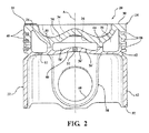
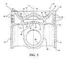
別の例示の実施形態によれば、図2および図3に示されるように、ピストン20は、ピストン20の中心軸Aに第1の下方クラウン面36に沿った下方クラウン冷却空洞26’を含む。この下方クラウン冷却空洞26’は、クラウン24の上壁38の一部に沿って配置されるのみであり、周方向の外側冷却空洞26によって取り囲まれる。上壁38、下壁40および内部側壁44は、ともに、下方クラウン冷却空洞26’を規定する。この実施形態では、下壁40は、燃焼面34の反対側に面する第2の下方クラウン面36’を含む。下方クラウン冷却空洞26’は、好ましくは、周方向の外側冷却空洞26との組合せで用いられるが、周方向の外側冷却空洞26と独立して用いられてもよい。下方クラウン冷却空洞26’はまた、第2の冷媒28’で少なくとも部分的に満たされてピストン20を通した熱の流れをさらに低減し、および/または、オイルの劣化を低減する。下方クラウン冷却空洞26’において用いられる第2の冷媒28’は、外側冷却空洞26において用いられる第1の冷媒28と同一であってもよく、または異なっていてもよい。
According to another exemplary embodiment, as shown in FIGS. 2 and 3, the
図2の実施形態では、下方クラウン冷却空洞26’は、第2の冷媒28’を含むために、および他の物質が冷却空洞26’に出入りできないように、封止される。別の実施形態によれば、図3に示されるように、下方クラウン冷却空洞26’は封止されない。空気が下方クラウン冷却空洞26’に入ることを可能にするために、小さな開いた入口穴46がピストン20の中心軸Aに沿って下壁40に位置する。入口穴46はまた、しぶきまたは霧の形態のクランク室からの少量のオイルが下方クラウン冷却空洞26’に入ることを可能にし得る。しかしながら、図2の実施形態では、下方クラウン冷却空洞26’への入口穴46は、栓52で封止される。入口穴46の直径は、ピストン20の外径の1%〜25%である。典型的には、入口穴46の直径は、ピストン20の外径の4%未満、または、ピストン20の外径の2%〜4%である。たとえば、入口穴46の直径は、約5mm以下であってもよい。任意で、入口穴46は、入口穴46の直径が下方クラウン冷却空洞26’の内側から外側へ、燃焼面34から離れるにつれて増加するように、テーパ状であってもよい。テーパ状の穴46は、下方クラウン冷却空洞26’の中へ入るオイルの進入を容易にし得、および/または、下方クラウン冷却空洞26’の内部の第2の冷媒28’を保持し得る。入口穴46の直径が下方クラウン冷却空洞26’の内側から外側へ、燃焼面34から離れるにつれて減少する、逆テーパ状の穴46も、下方クラウン冷却空洞26’の側部から穴を開ける製造工程を容易にするために用いられ得る。
In the embodiment of FIG. 2, the lower crown cooling cavity 26 'is sealed to contain the second refrigerant 28' and prevent other materials from entering or exiting the cooling cavity 26 '. According to another embodiment, the lower crown cooling cavity 26 'is not sealed, as shown in FIG. A small open inlet hole 46 is located in the
例示の実施形態のピストン20では、本体22の燃焼面34は、中心軸Aに頂点を有し、ボウル形状が頂点を取り囲み、ボウルリムがボウル形状を取り囲む。外部側壁42はまた、中心軸Aから離れて面し、中心軸Aの周りに周方向に延在する複数のリング溝56を含む。リング溝56は、ランド48によって互いに離間され、ランド48は本体22の外径を提示する。例示の実施形態のピストン20は、少なくとも1つのピンボス58、典型的にはクラウン24から各々垂下し中心軸Aの周りに周方向に延在する1対のピンボス58をさらに含む。少なくとも1つのピンボス58は、リストピン(図示せず)を収容するための中心軸Aに垂直に延在するピンボア60を有する。本体22は、クラウン24から垂下し中心軸Aの周りに周方向に延在する、少なくとも1つのスカートセクション、典型的には1対のスカートセクションも含む。少なくとも1つのスカートセクション62は、少なくとも1つのピンボス58と結合される。典型的には、スカートセクション62は、ピンボス58によって中心軸Aの周りに周方向に互いに離間される。ピストン20の本体22は、冷媒28および/または冷媒28’を含むための外側冷却空洞26および/または下方クラウン冷却空洞26’を依然として含むが、図1および図2に開示された設計以外の様々な他の設計を備えてもよいことに注意されたい。
In the
外側冷却空洞26に位置する第1の冷媒28および/または下方クラウン冷却空洞26’に位置する第2の冷媒28’は、気体、液体、固体、および/または、混合物の形態であってもよい。典型的には、冷媒28または冷媒28’が気体の形態であるとき、気体は冷却空洞26,26’の100体積パーセント(vol.%)を占める。たとえば、空気、ヘリウム、アルゴン、ヘリウム、キセノン、二酸化炭素、他の気体、または部分真空など、様々な異なるタイプの気体が冷媒28または冷媒28’のために用いられてもよい。気体の冷媒28または冷媒28’は、固体材料、多相の液体/気体混合物、および従来の冷却オイルなどの液体よりも低い熱伝導率を有する。たとえば、25℃で、空気は約0.024W/(m・K)の熱伝導率を有し、ヘリウムは約0.142W/(m・K)の熱伝導率を有し、アルゴンは約0.016W/(m・K)の熱伝導率を有する。1つの例示の実施形態によれば、下方クラウン冷却空洞26’を満たす第2の冷媒28’は、アルゴン、部分真空、または空気よりも熱流を低減することにおいてより効率的である他の気体である。そして、アルゴン、空気、または別のタイプの第1の冷媒28のいずれかが外側冷却空洞26を満たす。
The first refrigerant 28 located in the
別の例示の実施形態によれば、外側冷却空洞26を満たすもしくは部分的に満たす第1の冷媒28、および/または、下方クラウン冷却空洞26’を満たすもしくは部分的に満たす第2の冷媒28’は、液体、固体、または固体と液体との混合物である。冷媒28または冷媒28’として用いられ得る組成の例は、米国特許第9127619号、第8955486号、第8662026号、および米国仮特許出願第62/262,704号に開示されている。1つの例示の実施形態によれば、商品名エンビオクール(EnvioKool)(商標登録)を有する冷媒が、下方クラウン冷却空洞26’を部分的に満たす第2の冷媒28’として用いられる。この場合、空気または別のタイプの第1の冷媒28は、外側冷却空洞26を満たすまたは部分的に満たす。別の例示の実施形態によれば、第1の冷媒28は、空気からなり外側冷却空洞26の体積の100%を占め、第2の冷媒28’は、空気からなり下方クラウン冷却空洞26’の体積の100%を占める。
According to another exemplary embodiment, a first refrigerant 28 that fills or partially fills the
さらに別の実施形態によれば、標準的なエンジンオイルが外側冷却空洞26を部分的に満たす第1の冷媒28および/または下方クラウン冷却空洞26’を部分的に満たす第2の冷媒28’である。冷却空洞26,26’の1つのみがエンジンオイルを含む場合、空気または別のタイプの冷媒28,28’が他の冷却空洞26,26’を満たすまたは部分的に満たす。外側冷却空洞26および/または下方クラウン冷却空洞26’を部分的に満たすためにエンジンオイルが用いられる場合、エンジンオイルは、高い表面温度領域で冷却空洞26,26’の内面に沿ってコークス化されたオイル層を作り得る。このため、コークス化されたオイル層は、追加の断熱を作り得、ピストン20を通した熱損失をさらに低減する。
According to yet another embodiment, standard engine oil may include a first refrigerant 28 that partially fills the
冷媒28,28’の低い熱伝導率は、燃焼室の熱を維持し、ピストン20を通した熱損失の量を低減する。言い換えれば、低い熱伝導率は、ピストン20を通した燃焼室からの熱損失を低減し、燃焼室の温度を上昇させる。このため、冷媒28,28’は、断熱媒体またはピストン熱管理と呼ばれ得る。燃焼室における追加のエネルギは、この廃熱回収(waste heat recovery;WHR)システムで回収され得る。加えて、オイルコーキングは冷却空洞26の表面に沿って堆積し、第2の下方クラウン面36’は最小化または省略され得る。ピストン20と接触する冷却オイルおよび潤滑油の変質が低減され得る。冷媒28,28’は、また、ピストン20の下部の温度を最低化し得る。
The low thermal conductivity of the
追加の断熱を提供するために、図1、図2および図3に示されるように、熱障壁コーティング54がクラウン24の上壁38の燃焼面34に塗布され得る。熱障壁コーティング54は、下方クラウン冷却室26’を含まない図1のピストンの第1の下方クラウン面36に塗布され得る。代替的には、熱障壁コーティング54は、下方クラウン冷却空洞26’を含む図2および図3のピストン20の第2の下方クラウン面36’に塗布され得る。たとえば、図2および図3のピストン20は、第1の下方クラウン面36および第2の下方クラウン面36’の両方、またはそれらの面のただ1つの上に、熱障壁コーティング54を含み得る。熱障壁コーティング54は、ピストン本体22を形成するために用いられる金属の熱伝導率よりも低い熱伝導率を有する。熱障壁コーティング54は、たとえば、イットリア安定化ジルコニア、セリア安定化ジルコニア、または別のタイプの部分安定化ジルコニアなどの、セラミック系材料などの断熱材料で形成される。熱障壁コーティング54は、ピストン20を通した熱損失をさらに低減し、燃焼室温度を上昇させる。
In order to provide additional thermal insulation, a
本発明の別の局面は、外側冷却空洞26の第1の冷媒28および/または下方クラウン冷却空洞26’の第2の冷媒28’を含むピストン20を製造する方法を提供する。当該方法は、概して、鋼鉄材料で形成された本体22を提供するステップと、外側冷却空洞26および/または下方クラウン冷却空洞26’の少なくとも一部を冷媒28,28’で少なくとも部分的に満たすこととを含む。当該方法は、典型的には、外側冷却空洞26および/または下方クラウン冷却空洞26’を封止することも含む。
Another aspect of the invention provides a method of manufacturing a
図1〜図3で示される例示のピストン20を形成するとき、本体22を提供するステップは、上側リブを下側リブに結合して、その間に外側冷却空洞26を規定する内部側壁44および外部側壁42を形成することを含む。結合ステップは、溶接、結合溶接、機械的取付、またはリブを結合するための別の技術を用いることを含み得る。
When forming the
外側冷却空洞26を第1の冷媒28で満たすステップは、典型的には、クラウン24の壁38,40,42,44の1つ、典型的には下壁40に開口部52を形成することと、次いで開口部52を通して第1の冷媒28を送り込むこととを含む。この実施形態では、開口部52は結合ステップの前または後で形成されてもよく、冷却空洞26を満たすステップは結合ステップの後に起こる。最終的に、この方法は、栓で冷却空洞26への開口部52を封止することと、たとえば溶接、蝋付け、ねじ、または接着剤によって栓を固定することとを含む。参照によりここに組み込まれる米国仮特許出願第62/110,191は、冷却空洞26を封止するために用いられる例示の方法を開示している。代替的には、外側冷却空洞26は、オイル冷却噴射と位置合わせされない場合は、封止されないままであり得る開口部52を含んでいてもよい。開口部52に関して議論された同様のステップが、下方クラウン冷却空洞26’への入口穴46を満たし、封止するために行なわれてもよい。代替的には、下方クラウン冷却空洞26’は、小さい穴46を含んでもよく、封止されないままであってもよい。
The step of filling the
別の実施形態によれば、ピストン20は、封止された冷却空洞26を含む単一片として鋳造されてもよく、この場合、空気が封止された外側冷却空洞26を満たす第1の冷媒28である。他の実施形態では、部分真空、アルゴン、ヘリウム、キセノン、二酸化炭素、または、低い熱伝導率を有する別のガス、たとえば空気よりも熱流を低減させるのに効率的な気体が、冷却空洞26を封止する前に外側冷却空洞26および/または下方クラウン冷却空洞26’に配置される。ピストン20を製造するために用いられるプロセスは、従前の方法と比較してはるかに単純であり、より低いコストをもたらす。
According to another embodiment, the
明らかに、本発明の多くの改良および変形が上記の教示に照らせば可能であり、以下の請求項の範囲内で特定的に説明された以外の方法で実施され得る。 Obviously, many modifications and variations of the present invention are possible in light of the above teachings, and may be practiced otherwise than as specifically described within the scope of the following claims.
Claims (22)
金属材料で形成された本体を備え、
前記本体は、燃焼面を有するクラウンを含み、
前記クラウンは、前記燃焼面から垂下する外部側壁を含み、前記外部側壁は前記本体の外径を提示し、
前記クラウンは、外側冷却空洞と、下方クラウン冷却空洞とを含み、
前記外側冷却空洞は、前記燃焼面の下で前記外部側壁に沿って周方向に延在し、前記外側冷却空洞は封止され第1の冷媒を含み、
前記下方クラウン冷却空洞は、第1の下方クラウン面の下で前記外側冷却空洞によって取り囲まれ、前記外側冷却空洞は第2の冷媒を含み、
前記クラウンは、前記下方クラウン冷却空洞に沿って延在する下壁を含み、前記下壁は前記下方クラウン冷却空洞への入口穴を含む、ピストン。 A piston for an internal combustion engine,
With a body made of metal material,
The body includes a crown having a combustion surface;
The crown includes an outer sidewall depending from the combustion surface, the outer sidewall presenting an outer diameter of the body;
The crown includes an outer cooling cavity and a lower crown cooling cavity;
The outer cooling cavity extends circumferentially along the outer sidewall under the combustion surface, the outer cooling cavity is sealed and includes a first refrigerant;
The lower crown cooling cavity is surrounded by the outer cooling cavity under a first lower crown surface, the outer cooling cavity including a second refrigerant;
The piston includes a lower wall extending along the lower crown cooling cavity, the lower wall including an inlet hole to the lower crown cooling cavity.
前記クラウンは、前記燃焼面を有する上壁と、内部側壁とを含み、
前記上壁、前記下壁、前記外部側壁、および前記内部側壁は、ともに前記外側冷却空洞を規定し、
前記外側冷却空洞は、前記中心軸から径方向に離間されており、
前記外部側壁および前記内部側壁は、ともに結合されるリブによって形成され、
前記外部側壁、前記内部側壁、および前記下壁のうちの少なくとも1つは、冷媒が前記外側冷却空洞に入ることを可能にするための開口部を含み、前記開口部は封止されており、
前記下壁は、前記下方クラウン冷却空洞の下に第2の下方クラウン面を有し、
前記燃焼面は、前記中心軸に頂点を有し、ボウル形状が前記頂点を取り囲み、ボウルリムが前記ボウル形状を取り囲み、
前記外部側壁は、前記中心軸から離れて面し、前記中心軸の周りに周方向に延在する複数のリング溝を含み、前記リング溝はランドによって互いに離間されており、前記ランドは前記本体の前記外径を提示し、
前記本体は、前記クラウンから各々垂下する1対のピンボスを含み、前記ピンボスの各々は前記中心軸に垂直に延在するピンボアを有し、
前記本体は、前記クラウンから垂下し、前記ピンボスによって互いに離間される1対のスカートセクションを含み、
前記第1の冷媒は、前記外側冷却空洞の体積の100%を占め、前記第1の冷媒は空気からなり、
前記上壁、前記下壁、および前記内部側壁は、ともに前記下方クラウン冷却空洞を規定し、
前記下方クラウン冷却空洞は、前記中心軸に配置され、前記外側冷却空洞に向かって径方向外側に延在し、
前記第2の冷媒は、前記下方クラウン冷却空洞の堆積の100%を占め、前記第2の冷媒は空気からなり、
前記下方クラウン冷却空洞への前記入口穴は、前記スカートセクションに沿った前記本体の最大外径の2%〜4%である直径を有し、前記入口穴はテーパ状であり、
前記燃焼面、前記第1の下方クラウン面、および前記第2の下方クラウン面のうちの少なくとも1つに塗布される熱障壁コーティングをさらに含み、
前記熱障壁コーティングは、断熱材料で形成されており、前記断熱材料は部分安定化ジルコニアを含む、請求項1に記載のピストン。 The body is formed of steel, extends circumferentially around a central axis, and extends longitudinally from an upper end to a lower end;
The crown includes an upper wall having the combustion surface and an inner side wall;
The upper wall, the lower wall, the outer side wall, and the inner side wall together define the outer cooling cavity;
The outer cooling cavity is radially spaced from the central axis;
The outer side wall and the inner side wall are formed by ribs joined together;
At least one of the outer sidewall, the inner sidewall, and the lower wall includes an opening to allow refrigerant to enter the outer cooling cavity, the opening being sealed;
The lower wall has a second lower crown surface under the lower crown cooling cavity;
The combustion surface has a vertex on the central axis, a bowl shape surrounds the vertex, a bowl rim surrounds the bowl shape,
The outer sidewall includes a plurality of ring grooves facing away from the central axis and extending circumferentially around the central axis, the ring grooves being separated from one another by lands, the lands being the main body Presenting the outer diameter of
The body includes a pair of pin bosses each depending from the crown, each of the pin bosses having a pin bore extending perpendicular to the central axis;
The body includes a pair of skirt sections depending from the crown and spaced from each other by the pin bosses;
The first refrigerant occupies 100% of the volume of the outer cooling cavity, and the first refrigerant comprises air;
The upper wall, the lower wall, and the inner sidewall together define the lower crown cooling cavity;
The lower crown cooling cavity is disposed on the central axis and extends radially outward toward the outer cooling cavity;
The second refrigerant accounts for 100% of the deposition of the lower crown cooling cavity, the second refrigerant comprises air;
The inlet hole to the lower crown cooling cavity has a diameter that is 2% to 4% of the maximum outer diameter of the body along the skirt section, and the inlet hole is tapered;
Further comprising a thermal barrier coating applied to at least one of the combustion surface, the first lower crown surface, and the second lower crown surface;
The piston of claim 1, wherein the thermal barrier coating is formed of a heat insulating material, and the heat insulating material includes partially stabilized zirconia.
金属材料で形成された本体を提供するステップを備え、前記本体は燃焼面を有するクラウンを含み、前記クラウンは前記燃焼面から垂下する外部側壁を含み、前記外部側壁は前記本体の外径を提示し、前記クラウンは封止されている外側冷却空洞と、下方クラウン冷却空洞とを含み、前記外側冷却空洞は前記燃焼面の下で前記外部側壁に沿って周方向に延在し、前記下方クラウン冷却空洞は第1の下方クラウン面の下に前記外側冷却空洞によって取り囲まれ、前記クラウンは前記下方クラウン冷却空洞に沿って延在する下壁を含み、前記下壁は前記下方クラウン冷却空洞への入口穴を含み、前記方法はさらに、
前記外側冷却空洞の第1の冷媒および前記下方クラウン冷却空洞の第2の冷媒を提供するステップを備える、方法。 A method for manufacturing a piston for an internal combustion engine, comprising:
Providing a body formed of a metallic material, the body including a crown having a combustion surface, the crown including an outer sidewall depending from the combustion surface, the outer sidewall presenting an outer diameter of the body The crown includes a sealed outer cooling cavity and a lower crown cooling cavity, the outer cooling cavity extending circumferentially along the outer sidewall under the combustion surface and the lower crown A cooling cavity is surrounded by the outer cooling cavity below a first lower crown surface, the crown including a lower wall extending along the lower crown cooling cavity, the lower wall leading to the lower crown cooling cavity. An inlet hole, the method further comprising:
Providing a first refrigerant in the outer cooling cavity and a second refrigerant in the lower crown cooling cavity.
Applications Claiming Priority (7)
| Application Number | Priority Date | Filing Date | Title |
|---|---|---|---|
| US201562256986P | 2015-11-18 | 2015-11-18 | |
| US62/256,986 | 2015-11-18 | ||
| US201662280971P | 2016-01-20 | 2016-01-20 | |
| US62/280,971 | 2016-01-20 | ||
| US15/352,418 | 2016-11-15 | ||
| US15/352,418 US10294887B2 (en) | 2015-11-18 | 2016-11-15 | Piston providing for reduced heat loss using cooling media |
| PCT/US2016/062129 WO2017087433A1 (en) | 2015-11-18 | 2016-11-16 | Piston providing for reduced heat loss using cooling media |
Publications (2)
| Publication Number | Publication Date |
|---|---|
| JP2018534477A true JP2018534477A (en) | 2018-11-22 |
| JP2018534477A5 JP2018534477A5 (en) | 2019-06-13 |
Family
ID=58691805
Family Applications (1)
| Application Number | Title | Priority Date | Filing Date |
|---|---|---|---|
| JP2018525717A Pending JP2018534477A (en) | 2015-11-18 | 2016-11-16 | Piston that uses refrigerant to provide reduced heat loss |
Country Status (6)
| Country | Link |
|---|---|
| US (1) | US10294887B2 (en) |
| EP (1) | EP3377749B1 (en) |
| JP (1) | JP2018534477A (en) |
| KR (1) | KR102636266B1 (en) |
| CN (1) | CN110809669B (en) |
| WO (1) | WO2017087433A1 (en) |
Families Citing this family (4)
| Publication number | Priority date | Publication date | Assignee | Title |
|---|---|---|---|---|
| MX2018001895A (en) * | 2015-08-27 | 2018-06-20 | Ks Kolbenschmidt Gmbh | Piston of an internal combustion engine having alkali metal cooling and method for production thereof. |
| US10859033B2 (en) * | 2016-05-19 | 2020-12-08 | Tenneco Inc. | Piston having an undercrown surface with insulating coating and method of manufacture thereof |
| US20200217269A1 (en) * | 2019-01-04 | 2020-07-09 | Tenneco Inc. | Piston having an undercrown surface with insulating coating and method of manufacture thereof |
| DE102021213333A1 (en) | 2021-11-26 | 2023-06-01 | Federal-Mogul Nürnberg GmbH | Pistons with cooling cavities closed on all sides and filled with cooling medium |
Family Cites Families (88)
| Publication number | Priority date | Publication date | Assignee | Title |
|---|---|---|---|---|
| FR965449A (en) | 1950-09-12 | |||
| US1678957A (en) | 1925-01-29 | 1928-07-31 | Busch Sulzer Bros Diesel Engine Co | Piston cooling |
| US1719215A (en) | 1927-01-08 | 1929-07-02 | Faroy Arne | Internal-combustion engine |
| US1878566A (en) | 1929-02-01 | 1932-09-20 | Packard Motor Car Co | Internal combustion engine |
| US2126306A (en) | 1933-12-22 | 1938-08-09 | Bernard Renee | Piston for internal combustion engines |
| US2840427A (en) | 1955-06-10 | 1958-06-24 | Gen Motors Corp | Piston |
| US2772933A (en) | 1955-06-22 | 1956-12-04 | Alco Products Inc | Pistons |
| US3066002A (en) * | 1960-07-20 | 1962-11-27 | Jr Henry A Rudkin | Piston design |
| GB1091513A (en) | 1965-06-11 | 1967-11-15 | Mirrlees Nat Ltd | Improvements in or relating to pistons for internal combustion engines |
| US3385175A (en) | 1966-06-15 | 1968-05-28 | Mahle Kg | Piston |
| US3516335A (en) | 1968-07-03 | 1970-06-23 | Caterpillar Tractor Co | Piston with heat dam |
| US3613521A (en) | 1968-11-07 | 1971-10-19 | Komatsu Mfg Co Ltd | Piston for internal combustion engine |
| DE1956121A1 (en) | 1969-11-07 | 1971-05-27 | Kloeckner Humboldt Deutz Ag | Piston cooling for reciprocating internal combustion engines with spray nozzles that can be switched off |
| FR2238372A5 (en) | 1973-07-19 | 1975-02-14 | Dampers | |
| US4018194A (en) | 1975-01-06 | 1977-04-19 | Texaco Inc. | Engine piston with insulated combustion chamber |
| DE2612041A1 (en) | 1975-05-05 | 1976-11-25 | Caterpillar Tractor Co | ROTOR FOR ROTARY LISTON MACHINES |
| US4206726A (en) | 1977-07-18 | 1980-06-10 | Caterpillar Tractor Co. | Double orifice piston cooling nozzle for reciprocating engines |
| US4300492A (en) | 1978-05-22 | 1981-11-17 | Eaton Corporation | Thermal barrier valve |
| US4270494A (en) | 1979-01-11 | 1981-06-02 | General Motors Corporation | Insulated oil cooled piston assembly |
| US4253430A (en) | 1979-01-11 | 1981-03-03 | General Motors Corporation | Insulated oil cooled piston assembly |
| DE2919638A1 (en) | 1979-05-16 | 1980-11-20 | Schmidt Gmbh Karl | PISTON FOR INTERNAL COMBUSTION ENGINES |
| IT1194060B (en) | 1981-07-31 | 1988-09-14 | Ae Borgo Spa | DIESEL ENGINE PISTON WITH ISOLATED COMBUSTION CHAMBER |
| DE3222582C2 (en) | 1982-06-16 | 1985-10-03 | Berchem & Schaberg Gmbh, 4650 Gelsenkirchen | Method of manufacturing a piston crown blank by forging for an assembled piston |
| DE3329787A1 (en) | 1982-08-20 | 1984-02-23 | AE PLC, Rugby, Warwickshire | PISTON AND METHOD FOR THEIR PRODUCTION |
| US4517930A (en) | 1982-09-28 | 1985-05-21 | Kawasaki Jukogyo Kabushiki Kaisha | Piston of combustion engine |
| DE3470908D1 (en) | 1983-10-26 | 1988-06-09 | Mahle Gmbh | Multi-part piston for internal-combustion engines, having a partly isolated cooling oil conduit |
| US4546048A (en) | 1984-03-23 | 1985-10-08 | Dana Corporation | Composite thermal shield for engine components |
| DE3502644A1 (en) | 1985-01-26 | 1986-07-31 | M.A.N.-B & W Diesel GmbH, 8900 Augsburg | OIL-COOLED, MULTI-PIECE SUBMERSIBLE PISTON FOR PISTON PISTON COMBUSTION ENGINES |
| DE3511835A1 (en) | 1985-03-30 | 1986-10-09 | M.A.N.- B & W Diesel GmbH, 8900 Augsburg | Oil cooled trunk piston of an internal combustion engine |
| DE4118400A1 (en) | 1990-06-29 | 1992-01-02 | Kolbenschmidt Ag | BUILT OIL-COOLED PISTON FOR DIESEL ENGINES |
| DE4040611A1 (en) | 1990-12-19 | 1992-07-02 | Man B & W Diesel Ag | Jet piston cooling for IC engines - has air accumulation chamber in piston base |
| DE4120850A1 (en) | 1991-06-25 | 1993-01-07 | Kolbenschmidt Ag | BUILT OIL-COOLED PISTON FOR DIESEL ENGINES |
| JP3198706B2 (en) * | 1993-03-09 | 2001-08-13 | アイシン精機株式会社 | Manufacturing method of piston with cooling cavity |
| DE4430137B4 (en) | 1994-08-25 | 2004-07-22 | Mahle Gmbh | Multi-part, cooled piston for internal combustion engines |
| DE19618625C1 (en) | 1996-05-09 | 1997-10-23 | Daimler Benz Ag | Liquid-cooled pistons for internal combustion engines |
| US6003479A (en) | 1997-05-12 | 1999-12-21 | Evans; Mark M. | Piston construction |
| US6477941B1 (en) | 1999-10-08 | 2002-11-12 | Federal-Mogul World Wide, Inc. | Dual gallery piston |
| US20010025568A1 (en) | 2000-03-28 | 2001-10-04 | Mahle Gmbh | One-piece piston |
| DE60139329D1 (en) | 2000-10-18 | 2009-09-03 | Federal Mogul Corp | MEHRAXIAL FORGED PISTON |
| BR0211660A (en) | 2001-07-30 | 2004-07-13 | Roberto Oscar Appo | An assembly of a sheet metal ring mounted and welded in a carrier arc to fit the annular refrigeration pipe of an internal combustion engine piston, method for producing a die-cast sheet metal ring to obtain a plate ring metallic |
| US6513477B1 (en) | 2001-09-19 | 2003-02-04 | Federal-Mogul World Wide, Inc. | Closed gallery piston having pin bore lubrication |
| US6539910B1 (en) | 2001-09-19 | 2003-04-01 | Federal-Mogul World Wide, Inc. | Closed gallery piston having con rod lubrication |
| US6491013B1 (en) | 2001-09-19 | 2002-12-10 | Federal-Mogul World Wide, Inc. | Closed gallery piston having reinforced oil hole |
| US6862976B2 (en) * | 2001-10-23 | 2005-03-08 | Federal-Mogul World Wide, Inc. | Monobloc piston |
| DE10214830A1 (en) | 2002-04-04 | 2004-01-08 | Mahle Gmbh | Oil inlet for a piston of an internal combustion engine provided with a cooling channel |
| DE10257022A1 (en) | 2002-12-06 | 2004-06-17 | Mahle Gmbh | Multi-part cooled piston for an internal combustion engine |
| FR2854089B1 (en) | 2003-04-23 | 2006-05-19 | Semt Pielstick | METHOD FOR MANUFACTURING A PISTON, TOOLING FOR CARRYING OUT SAID METHOD, AND PISTON THUS OBTAINED |
| WO2005066481A1 (en) | 2004-01-07 | 2005-07-21 | Komatsu Ltd. | Piston for internal combustion engine |
| DE102005042857A1 (en) | 2005-09-08 | 2007-03-22 | Ks Kolbenschmidt Gmbh | Piston for an internal combustion engine |
| CN1944994A (en) | 2005-10-08 | 2007-04-11 | 山东滨州渤海活塞股份有限公司 | Welded forged steel integrated piston and its producing method |
| DE102006027354A1 (en) * | 2006-06-13 | 2007-12-20 | Mahle International Gmbh | Multi-piece cooled piston for an internal combustion engine |
| US7654240B2 (en) | 2006-08-18 | 2010-02-02 | Caterpillar Inc. | Engine piston having an insulating air gap |
| DE102006055251A1 (en) | 2006-11-23 | 2008-05-29 | Mahle International Gmbh | Two-piece piston for an internal combustion engine |
| CN101092914A (en) | 2007-07-20 | 2007-12-26 | 山东滨州渤海活塞股份有限公司 | Welding type single piece piston in forged steel with close internal cooling oil pocket and fabricating method |
| US20110203545A1 (en) | 2008-09-05 | 2011-08-25 | Ks Kolbenschmidt Gmbh | Method For Manufacturing A Piston Of An Internal Combustion Engine, Comprising An Improved Aluminum Silicon Alloy |
| DE102008055848A1 (en) | 2008-11-04 | 2010-05-06 | Ks Kolbenschmidt Gmbh | Cooling channel piston of an internal combustion engine with a closure element which closes the cooling channel |
| DE102008056203A1 (en) | 2008-11-06 | 2010-05-12 | Mahle International Gmbh | Multi-part piston for an internal combustion engine and method for its production |
| US8601996B2 (en) | 2009-05-08 | 2013-12-10 | Caterpillar Inc. | Single piece piston body for an internal combustion engine |
| US20110073061A1 (en) * | 2009-09-28 | 2011-03-31 | Jeungsuck Chae | Pistons with a rough surface |
| US8327537B2 (en) | 2009-12-23 | 2012-12-11 | Federal Mogul Corporation | Reinforced dual gallery piston and method of construction |
| US20110197845A1 (en) | 2010-02-17 | 2011-08-18 | William Flowers | Piston assembly |
| DE102010009891A1 (en) * | 2010-03-02 | 2011-09-08 | Mahle International Gmbh | Piston for an internal combustion engine |
| DE102010015568A1 (en) | 2010-04-19 | 2011-10-20 | Ks Kolbenschmidt Gmbh | Piston upper part of a built or welded piston with extended cooling chambers |
| US9856820B2 (en) | 2010-10-05 | 2018-01-02 | Mahle International Gmbh | Piston assembly |
| US8522745B2 (en) | 2010-10-25 | 2013-09-03 | Eddie H. Doss | Reinforced piston and connecting rod assembly |
| DE102010051681B4 (en) | 2010-11-17 | 2019-09-12 | Daimler Ag | Method for producing a cooling channel piston |
| US8863381B2 (en) | 2010-12-22 | 2014-10-21 | GM Global Technology Operations LLC | Method of making a piston oil gallery using a hollow metallic core |
| US8863647B2 (en) | 2011-05-04 | 2014-10-21 | GM Global Technology Operations LLC | Oil gallery piston with improved thermal conductivity |
| US8973484B2 (en) | 2011-07-01 | 2015-03-10 | Mahle Industries Inc. | Piston with cooling gallery |
| DE102011111319A1 (en) | 2011-08-26 | 2013-02-28 | Mahle International Gmbh | Piston for an internal combustion engine |
| US9593641B2 (en) | 2011-09-21 | 2017-03-14 | Mahle International Gmbh | Laser welded piston assembly |
| US8739755B2 (en) | 2011-10-24 | 2014-06-03 | Mahle International Gmbh | Piston for an internal combustion engine |
| DE102011085442A1 (en) | 2011-10-28 | 2013-05-02 | Ks Kolbenschmidt Gmbh | Method and machine tool for machining |
| US9169800B2 (en) | 2011-11-28 | 2015-10-27 | Federal-Mogul Corporation | Piston with anti-carbon deposit coating and method of construction thereof |
| US9163579B2 (en) | 2011-11-28 | 2015-10-20 | Federal-Mogul Corporation | Piston with anti-carbon deposit coating and method of construction thereof |
| US8955486B2 (en) | 2012-02-10 | 2015-02-17 | Federal Mogul Corporation | Piston with enhanced cooling gallery |
| US8955487B2 (en) | 2012-02-10 | 2015-02-17 | Federal-Mogul Corporation | Piston and cooled piston ring therefor and method of construction thereof |
| US8662026B2 (en) * | 2012-02-10 | 2014-03-04 | Federal-Mogul Corporation | Piston with supplemental cooling gallery and internal combustion engine therewith |
| DE102012206392A1 (en) | 2012-04-18 | 2013-10-24 | Mahle International Gmbh | Piston for an internal combustion engine |
| JP2014034917A (en) * | 2012-08-08 | 2014-02-24 | Hino Motors Ltd | Piston structure of engine |
| DE102012215541A1 (en) | 2012-08-31 | 2014-03-06 | Mahle International Gmbh | piston |
| EP3382187A1 (en) | 2012-09-27 | 2018-10-03 | Federal-Mogul Corporation | Reduced comprression height piston and piston assembly therewith and methods of construction thereof |
| US9127619B2 (en) | 2012-11-02 | 2015-09-08 | Federal-Mogul Corporation | Piston with a cooling gallery partially filled with a thermally conductive metal-containing composition |
| US9631576B2 (en) | 2013-02-22 | 2017-04-25 | Mahle International Gmbh | Piston assembly with weld support |
| US9291119B2 (en) | 2013-03-14 | 2016-03-22 | Mahle International Gmbh | Piston assembly with preloaded support surfaces |
| KR101383121B1 (en) | 2013-07-01 | 2014-04-09 | 삼영기계주식회사 | A piston assembly |
| KR20160146925A (en) * | 2014-04-30 | 2016-12-21 | 페더럴-모걸 코오포레이숀 | Steel piston with filled gallery |
| US10184422B2 (en) | 2014-12-30 | 2019-01-22 | Tenneco Inc. | Reduced compression height dual gallery piston, piston assembly therewith and methods of construction thereof |
-
2016
- 2016-11-15 US US15/352,418 patent/US10294887B2/en active Active
- 2016-11-16 EP EP16806358.4A patent/EP3377749B1/en active Active
- 2016-11-16 WO PCT/US2016/062129 patent/WO2017087433A1/en active Application Filing
- 2016-11-16 JP JP2018525717A patent/JP2018534477A/en active Pending
- 2016-11-16 CN CN201680079247.4A patent/CN110809669B/en active Active
- 2016-11-16 KR KR1020187015595A patent/KR102636266B1/en active IP Right Grant
Also Published As
| Publication number | Publication date |
|---|---|
| US20170138296A1 (en) | 2017-05-18 |
| KR20180081755A (en) | 2018-07-17 |
| US10294887B2 (en) | 2019-05-21 |
| WO2017087433A1 (en) | 2017-05-26 |
| EP3377749B1 (en) | 2021-11-03 |
| CN110809669A (en) | 2020-02-18 |
| KR102636266B1 (en) | 2024-02-16 |
| CN110809669B (en) | 2022-03-18 |
| EP3377749A1 (en) | 2018-09-26 |
Similar Documents
| Publication | Publication Date | Title |
|---|---|---|
| JP2018534477A (en) | Piston that uses refrigerant to provide reduced heat loss | |
| US11067033B2 (en) | Dual gallery steel piston | |
| CN106224110B (en) | Cylinder liner assembly with thermal barrier coating | |
| US9765728B2 (en) | Piston for an internal combustion engine | |
| US9127619B2 (en) | Piston with a cooling gallery partially filled with a thermally conductive metal-containing composition | |
| JP6324902B2 (en) | Integrated piston with improved combustion bowl edge region and method of manufacture | |
| JP6663356B2 (en) | Steel piston with filled gallery | |
| US10859033B2 (en) | Piston having an undercrown surface with insulating coating and method of manufacture thereof | |
| US10704491B2 (en) | Piston cooling gallery shaping to reduce piston temperature | |
| JP2018534477A5 (en) | ||
| CN109763911A (en) | Bimetal piston head including heat insulating coat | |
| JP2018508691A (en) | Piston with cooling cavity cooling insert and method of construction | |
| JP2019501326A (en) | Piston having a sealed cooling cavity containing a thermally conductive composition | |
| US10731598B2 (en) | Piston having an undercrown surface with coating and method of manufacture thereof | |
| EP3250806B1 (en) | Piston with sealed cooling gallery and method of construction thereof | |
| JPH03264714A (en) | Hollow poppet valve |
Legal Events
| Date | Code | Title | Description |
|---|---|---|---|
| A711 | Notification of change in applicant |
Free format text: JAPANESE INTERMEDIATE CODE: A712 Effective date: 20181108 |
|
| A521 | Request for written amendment filed |
Free format text: JAPANESE INTERMEDIATE CODE: A523 Effective date: 20190513 |
|
| A621 | Written request for application examination |
Free format text: JAPANESE INTERMEDIATE CODE: A621 Effective date: 20190513 |
|
| A131 | Notification of reasons for refusal |
Free format text: JAPANESE INTERMEDIATE CODE: A131 Effective date: 20200602 |
|
| A02 | Decision of refusal |
Free format text: JAPANESE INTERMEDIATE CODE: A02 Effective date: 20210105 |