JP2018530102A - Diatom energy storage device - Google Patents
Diatom energy storage device Download PDFInfo
- Publication number
- JP2018530102A JP2018530102A JP2017567454A JP2017567454A JP2018530102A JP 2018530102 A JP2018530102 A JP 2018530102A JP 2017567454 A JP2017567454 A JP 2017567454A JP 2017567454 A JP2017567454 A JP 2017567454A JP 2018530102 A JP2018530102 A JP 2018530102A
- Authority
- JP
- Japan
- Prior art keywords
- shell
- electrode
- diatom
- energy storage
- nanostructures
- Prior art date
- Legal status (The legal status is an assumption and is not a legal conclusion. Google has not performed a legal analysis and makes no representation as to the accuracy of the status listed.)
- Pending
Links
- 238000004146 energy storage Methods 0.000 title claims abstract description 230
- 239000002086 nanomaterial Substances 0.000 claims abstract description 356
- XLOMVQKBTHCTTD-UHFFFAOYSA-N Zinc monoxide Chemical compound [Zn]=O XLOMVQKBTHCTTD-UHFFFAOYSA-N 0.000 claims abstract description 298
- 239000011787 zinc oxide Substances 0.000 claims abstract description 137
- 210000002637 putamen Anatomy 0.000 claims abstract description 134
- 239000011572 manganese Substances 0.000 claims abstract description 120
- 229910052748 manganese Inorganic materials 0.000 claims abstract description 66
- PWHULOQIROXLJO-UHFFFAOYSA-N Manganese Chemical compound [Mn] PWHULOQIROXLJO-UHFFFAOYSA-N 0.000 claims abstract description 65
- 238000000034 method Methods 0.000 claims description 211
- AMWRITDGCCNYAT-UHFFFAOYSA-L hydroxy(oxo)manganese;manganese Chemical compound [Mn].O[Mn]=O.O[Mn]=O AMWRITDGCCNYAT-UHFFFAOYSA-L 0.000 claims description 151
- OKTJSMMVPCPJKN-UHFFFAOYSA-N Carbon Chemical compound [C] OKTJSMMVPCPJKN-UHFFFAOYSA-N 0.000 claims description 111
- 239000003792 electrolyte Substances 0.000 claims description 70
- 239000002608 ionic liquid Substances 0.000 claims description 37
- 239000011231 conductive filler Substances 0.000 claims description 36
- 239000011148 porous material Substances 0.000 claims description 36
- 239000002041 carbon nanotube Substances 0.000 claims description 34
- 229910021393 carbon nanotube Inorganic materials 0.000 claims description 34
- 239000002070 nanowire Substances 0.000 claims description 34
- 150000003839 salts Chemical class 0.000 claims description 33
- 239000010439 graphite Substances 0.000 claims description 26
- 229910002804 graphite Inorganic materials 0.000 claims description 26
- 239000002105 nanoparticle Substances 0.000 claims description 23
- 230000004048 modification Effects 0.000 claims description 19
- 238000012986 modification Methods 0.000 claims description 19
- 239000002055 nanoplate Substances 0.000 claims description 17
- 239000002127 nanobelt Substances 0.000 claims description 14
- 150000003751 zinc Chemical class 0.000 claims description 7
- WPBNNNQJVZRUHP-UHFFFAOYSA-L manganese(2+);methyl n-[[2-(methoxycarbonylcarbamothioylamino)phenyl]carbamothioyl]carbamate;n-[2-(sulfidocarbothioylamino)ethyl]carbamodithioate Chemical compound [Mn+2].[S-]C(=S)NCCNC([S-])=S.COC(=O)NC(=S)NC1=CC=CC=C1NC(=S)NC(=O)OC WPBNNNQJVZRUHP-UHFFFAOYSA-L 0.000 claims description 5
- 229910003174 MnOOH Inorganic materials 0.000 claims 3
- 239000011257 shell material Substances 0.000 description 807
- BQCADISMDOOEFD-UHFFFAOYSA-N Silver Chemical compound [Ag] BQCADISMDOOEFD-UHFFFAOYSA-N 0.000 description 226
- 229910052709 silver Inorganic materials 0.000 description 224
- 239000004332 silver Substances 0.000 description 224
- 239000000976 ink Substances 0.000 description 161
- 239000000463 material Substances 0.000 description 150
- 239000010410 layer Substances 0.000 description 126
- 239000000203 mixture Substances 0.000 description 102
- 239000002904 solvent Substances 0.000 description 102
- 238000007639 printing Methods 0.000 description 83
- 238000010438 heat treatment Methods 0.000 description 76
- -1 lauryl methyl Chemical group 0.000 description 73
- 239000000243 solution Substances 0.000 description 73
- 230000008569 process Effects 0.000 description 67
- 238000005119 centrifugation Methods 0.000 description 65
- 238000000926 separation method Methods 0.000 description 64
- 238000002156 mixing Methods 0.000 description 58
- 239000008247 solid mixture Substances 0.000 description 56
- 238000001878 scanning electron micrograph Methods 0.000 description 49
- 239000004094 surface-active agent Substances 0.000 description 48
- XLYOFNOQVPJJNP-UHFFFAOYSA-N water Substances O XLYOFNOQVPJJNP-UHFFFAOYSA-N 0.000 description 47
- LFQSCWFLJHTTHZ-UHFFFAOYSA-N Ethanol Chemical compound CCO LFQSCWFLJHTTHZ-UHFFFAOYSA-N 0.000 description 46
- UQSXHKLRYXJYBZ-UHFFFAOYSA-N Iron oxide Chemical compound [Fe]=O UQSXHKLRYXJYBZ-UHFFFAOYSA-N 0.000 description 46
- VYPSYNLAJGMNEJ-UHFFFAOYSA-N Silicium dioxide Chemical compound O=[Si]=O VYPSYNLAJGMNEJ-UHFFFAOYSA-N 0.000 description 46
- LYCAIKOWRPUZTN-UHFFFAOYSA-N ethylene glycol Natural products OCCO LYCAIKOWRPUZTN-UHFFFAOYSA-N 0.000 description 46
- 239000012528 membrane Substances 0.000 description 45
- 239000000356 contaminant Substances 0.000 description 39
- 238000004519 manufacturing process Methods 0.000 description 37
- 230000002776 aggregation Effects 0.000 description 36
- 239000006185 dispersion Substances 0.000 description 36
- 239000000654 additive Substances 0.000 description 35
- 238000000576 coating method Methods 0.000 description 35
- 241000206761 Bacillariophyta Species 0.000 description 34
- ZMXDDKWLCZADIW-UHFFFAOYSA-N N,N-Dimethylformamide Chemical compound CN(C)C=O ZMXDDKWLCZADIW-UHFFFAOYSA-N 0.000 description 34
- PXHVJJICTQNCMI-UHFFFAOYSA-N Nickel Chemical compound [Ni] PXHVJJICTQNCMI-UHFFFAOYSA-N 0.000 description 34
- 229910052799 carbon Inorganic materials 0.000 description 33
- 239000004065 semiconductor Substances 0.000 description 32
- 239000010949 copper Substances 0.000 description 31
- 239000002245 particle Substances 0.000 description 31
- 229920000642 polymer Polymers 0.000 description 31
- 239000004020 conductor Substances 0.000 description 30
- 239000007789 gas Substances 0.000 description 29
- 230000012010 growth Effects 0.000 description 29
- 239000003638 chemical reducing agent Substances 0.000 description 28
- HEMHJVSKTPXQMS-UHFFFAOYSA-M Sodium hydroxide Chemical compound [OH-].[Na+] HEMHJVSKTPXQMS-UHFFFAOYSA-M 0.000 description 27
- 230000015572 biosynthetic process Effects 0.000 description 27
- 239000011248 coating agent Substances 0.000 description 27
- VEXZGXHMUGYJMC-UHFFFAOYSA-N Hydrochloric acid Chemical compound Cl VEXZGXHMUGYJMC-UHFFFAOYSA-N 0.000 description 26
- 238000004140 cleaning Methods 0.000 description 26
- 239000000758 substrate Substances 0.000 description 26
- RYGMFSIKBFXOCR-UHFFFAOYSA-N Copper Chemical compound [Cu] RYGMFSIKBFXOCR-UHFFFAOYSA-N 0.000 description 25
- 239000000853 adhesive Substances 0.000 description 25
- 230000001070 adhesive effect Effects 0.000 description 25
- 241000894007 species Species 0.000 description 25
- 238000004220 aggregation Methods 0.000 description 24
- 229910052782 aluminium Inorganic materials 0.000 description 24
- XAGFODPZIPBFFR-UHFFFAOYSA-N aluminium Chemical compound [Al] XAGFODPZIPBFFR-UHFFFAOYSA-N 0.000 description 24
- 229910052802 copper Inorganic materials 0.000 description 24
- NDVLTYZPCACLMA-UHFFFAOYSA-N silver oxide Chemical compound [O-2].[Ag+].[Ag+] NDVLTYZPCACLMA-UHFFFAOYSA-N 0.000 description 24
- 230000000996 additive effect Effects 0.000 description 23
- PPNAOCWZXJOHFK-UHFFFAOYSA-N manganese(2+);oxygen(2-) Chemical class [O-2].[Mn+2] PPNAOCWZXJOHFK-UHFFFAOYSA-N 0.000 description 22
- 239000005909 Kieselgur Substances 0.000 description 21
- DNIAPMSPPWPWGF-UHFFFAOYSA-N Propylene glycol Chemical group CC(O)CO DNIAPMSPPWPWGF-UHFFFAOYSA-N 0.000 description 21
- 239000011777 magnesium Substances 0.000 description 20
- IAZDPXIOMUYVGZ-UHFFFAOYSA-N Dimethylsulphoxide Chemical compound CS(C)=O IAZDPXIOMUYVGZ-UHFFFAOYSA-N 0.000 description 19
- FYYHWMGAXLPEAU-UHFFFAOYSA-N Magnesium Chemical compound [Mg] FYYHWMGAXLPEAU-UHFFFAOYSA-N 0.000 description 18
- QAOWNCQODCNURD-UHFFFAOYSA-N Sulfuric acid Chemical compound OS(O)(=O)=O QAOWNCQODCNURD-UHFFFAOYSA-N 0.000 description 18
- 229910021389 graphene Inorganic materials 0.000 description 18
- VKYKSIONXSXAKP-UHFFFAOYSA-N hexamethylenetetramine Chemical compound C1N(C2)CN3CN1CN2C3 VKYKSIONXSXAKP-UHFFFAOYSA-N 0.000 description 18
- 229910052749 magnesium Inorganic materials 0.000 description 18
- XEEYBQQBJWHFJM-UHFFFAOYSA-N Iron Chemical compound [Fe] XEEYBQQBJWHFJM-UHFFFAOYSA-N 0.000 description 17
- XUIMIQQOPSSXEZ-UHFFFAOYSA-N Silicon Chemical compound [Si] XUIMIQQOPSSXEZ-UHFFFAOYSA-N 0.000 description 17
- RTZKZFJDLAIYFH-UHFFFAOYSA-N ether Substances CCOCC RTZKZFJDLAIYFH-UHFFFAOYSA-N 0.000 description 17
- 238000001914 filtration Methods 0.000 description 17
- 238000007873 sieving Methods 0.000 description 17
- 229910052710 silicon Inorganic materials 0.000 description 17
- 239000010703 silicon Substances 0.000 description 17
- 238000000527 sonication Methods 0.000 description 17
- 239000011701 zinc Substances 0.000 description 17
- NLXLAEXVIDQMFP-UHFFFAOYSA-N Ammonia chloride Chemical compound [NH4+].[Cl-] NLXLAEXVIDQMFP-UHFFFAOYSA-N 0.000 description 16
- MHAJPDPJQMAIIY-UHFFFAOYSA-N Hydrogen peroxide Chemical compound OO MHAJPDPJQMAIIY-UHFFFAOYSA-N 0.000 description 16
- WHXSMMKQMYFTQS-UHFFFAOYSA-N Lithium Chemical compound [Li] WHXSMMKQMYFTQS-UHFFFAOYSA-N 0.000 description 16
- 229910052732 germanium Inorganic materials 0.000 description 16
- GNPVGFCGXDBREM-UHFFFAOYSA-N germanium atom Chemical compound [Ge] GNPVGFCGXDBREM-UHFFFAOYSA-N 0.000 description 16
- 230000002401 inhibitory effect Effects 0.000 description 16
- 229910052744 lithium Inorganic materials 0.000 description 16
- VASIZKWUTCETSD-UHFFFAOYSA-N manganese(II) oxide Inorganic materials [Mn]=O VASIZKWUTCETSD-UHFFFAOYSA-N 0.000 description 16
- SQGYOTSLMSWVJD-UHFFFAOYSA-N silver(1+) nitrate Chemical compound [Ag+].[O-]N(=O)=O SQGYOTSLMSWVJD-UHFFFAOYSA-N 0.000 description 16
- 229910001369 Brass Inorganic materials 0.000 description 15
- 239000010951 brass Substances 0.000 description 15
- 239000007788 liquid Substances 0.000 description 15
- UOGMEBQRZBEZQT-UHFFFAOYSA-L manganese(2+);diacetate Chemical compound [Mn+2].CC([O-])=O.CC([O-])=O UOGMEBQRZBEZQT-UHFFFAOYSA-L 0.000 description 15
- 229910052751 metal Inorganic materials 0.000 description 15
- 239000002184 metal Substances 0.000 description 15
- GLDOVTGHNKAZLK-UHFFFAOYSA-N octadecan-1-ol Chemical compound CCCCCCCCCCCCCCCCCCO GLDOVTGHNKAZLK-UHFFFAOYSA-N 0.000 description 15
- 239000000126 substance Substances 0.000 description 15
- 229910052715 tantalum Inorganic materials 0.000 description 15
- GUVRBAGPIYLISA-UHFFFAOYSA-N tantalum atom Chemical compound [Ta] GUVRBAGPIYLISA-UHFFFAOYSA-N 0.000 description 15
- QGZKDVFQNNGYKY-UHFFFAOYSA-N Ammonia Chemical compound N QGZKDVFQNNGYKY-UHFFFAOYSA-N 0.000 description 14
- JBRZTFJDHDCESZ-UHFFFAOYSA-N AsGa Chemical compound [As]#[Ga] JBRZTFJDHDCESZ-UHFFFAOYSA-N 0.000 description 14
- 229910001218 Gallium arsenide Inorganic materials 0.000 description 14
- ATHHXGZTWNVVOU-UHFFFAOYSA-N N-methylformamide Chemical compound CNC=O ATHHXGZTWNVVOU-UHFFFAOYSA-N 0.000 description 14
- 229910000577 Silicon-germanium Inorganic materials 0.000 description 14
- WYURNTSHIVDZCO-UHFFFAOYSA-N Tetrahydrofuran Chemical compound C1CCOC1 WYURNTSHIVDZCO-UHFFFAOYSA-N 0.000 description 14
- LEVVHYCKPQWKOP-UHFFFAOYSA-N [Si].[Ge] Chemical compound [Si].[Ge] LEVVHYCKPQWKOP-UHFFFAOYSA-N 0.000 description 14
- 239000011149 active material Substances 0.000 description 14
- 239000002585 base Substances 0.000 description 14
- 238000001723 curing Methods 0.000 description 14
- WGCNASOHLSPBMP-UHFFFAOYSA-N hydroxyacetaldehyde Natural products OCC=O WGCNASOHLSPBMP-UHFFFAOYSA-N 0.000 description 14
- 229940071125 manganese acetate Drugs 0.000 description 14
- 229910052759 nickel Inorganic materials 0.000 description 14
- WGTYBPLFGIVFAS-UHFFFAOYSA-M tetramethylammonium hydroxide Chemical compound [OH-].C[N+](C)(C)C WGTYBPLFGIVFAS-UHFFFAOYSA-M 0.000 description 14
- KBPLFHHGFOOTCA-UHFFFAOYSA-N 1-Octanol Chemical compound CCCCCCCCO KBPLFHHGFOOTCA-UHFFFAOYSA-N 0.000 description 13
- KFZMGEQAYNKOFK-UHFFFAOYSA-N Isopropanol Chemical compound CC(C)O KFZMGEQAYNKOFK-UHFFFAOYSA-N 0.000 description 13
- SECXISVLQFMRJM-UHFFFAOYSA-N N-Methylpyrrolidone Chemical compound CN1CCCC1=O SECXISVLQFMRJM-UHFFFAOYSA-N 0.000 description 13
- KWYUFKZDYYNOTN-UHFFFAOYSA-M Potassium hydroxide Chemical compound [OH-].[K+] KWYUFKZDYYNOTN-UHFFFAOYSA-M 0.000 description 13
- 239000000123 paper Substances 0.000 description 13
- VHUUQVKOLVNVRT-UHFFFAOYSA-N Ammonium hydroxide Chemical compound [NH4+].[OH-] VHUUQVKOLVNVRT-UHFFFAOYSA-N 0.000 description 12
- 229920003171 Poly (ethylene oxide) Polymers 0.000 description 12
- 238000005054 agglomeration Methods 0.000 description 12
- 235000011114 ammonium hydroxide Nutrition 0.000 description 12
- 239000003990 capacitor Substances 0.000 description 12
- MTHSVFCYNBDYFN-UHFFFAOYSA-N diethylene glycol Chemical compound OCCOCCO MTHSVFCYNBDYFN-UHFFFAOYSA-N 0.000 description 12
- 230000009467 reduction Effects 0.000 description 12
- 229910001923 silver oxide Inorganic materials 0.000 description 12
- LRHPLDYGYMQRHN-UHFFFAOYSA-N N-Butanol Chemical compound CCCCO LRHPLDYGYMQRHN-UHFFFAOYSA-N 0.000 description 11
- 239000011230 binding agent Substances 0.000 description 11
- BASFCYQUMIYNBI-UHFFFAOYSA-N platinum Chemical compound [Pt] BASFCYQUMIYNBI-UHFFFAOYSA-N 0.000 description 11
- 238000005406 washing Methods 0.000 description 11
- XKRFYHLGVUSROY-UHFFFAOYSA-N Argon Chemical compound [Ar] XKRFYHLGVUSROY-UHFFFAOYSA-N 0.000 description 10
- WCUXLLCKKVVCTQ-UHFFFAOYSA-M Potassium chloride Chemical compound [Cl-].[K+] WCUXLLCKKVVCTQ-UHFFFAOYSA-M 0.000 description 10
- 239000002253 acid Substances 0.000 description 10
- 239000000908 ammonium hydroxide Substances 0.000 description 10
- 238000000137 annealing Methods 0.000 description 10
- 239000007844 bleaching agent Substances 0.000 description 10
- 230000005587 bubbling Effects 0.000 description 10
- WERYXYBDKMZEQL-UHFFFAOYSA-N butane-1,4-diol Chemical compound OCCCCO WERYXYBDKMZEQL-UHFFFAOYSA-N 0.000 description 10
- 239000003093 cationic surfactant Substances 0.000 description 10
- BXWNKGSJHAJOGX-UHFFFAOYSA-N hexadecan-1-ol Chemical compound CCCCCCCCCCCCCCCCO BXWNKGSJHAJOGX-UHFFFAOYSA-N 0.000 description 10
- 239000002736 nonionic surfactant Substances 0.000 description 10
- 229920001223 polyethylene glycol Polymers 0.000 description 10
- BDERNNFJNOPAEC-UHFFFAOYSA-N propan-1-ol Chemical compound CCCO BDERNNFJNOPAEC-UHFFFAOYSA-N 0.000 description 10
- 229910052725 zinc Inorganic materials 0.000 description 10
- ZWEHNKRNPOVVGH-UHFFFAOYSA-N 2-Butanone Chemical compound CCC(C)=O ZWEHNKRNPOVVGH-UHFFFAOYSA-N 0.000 description 9
- CSCPPACGZOOCGX-UHFFFAOYSA-N Acetone Chemical compound CC(C)=O CSCPPACGZOOCGX-UHFFFAOYSA-N 0.000 description 9
- WEVYAHXRMPXWCK-UHFFFAOYSA-N Acetonitrile Chemical compound CC#N WEVYAHXRMPXWCK-UHFFFAOYSA-N 0.000 description 9
- OKKJLVBELUTLKV-UHFFFAOYSA-N Methanol Chemical compound OC OKKJLVBELUTLKV-UHFFFAOYSA-N 0.000 description 9
- HCHKCACWOHOZIP-UHFFFAOYSA-N Zinc Chemical compound [Zn] HCHKCACWOHOZIP-UHFFFAOYSA-N 0.000 description 9
- BTANRVKWQNVYAZ-UHFFFAOYSA-N butan-2-ol Chemical compound CCC(C)O BTANRVKWQNVYAZ-UHFFFAOYSA-N 0.000 description 9
- 238000000227 grinding Methods 0.000 description 9
- 229960004063 propylene glycol Drugs 0.000 description 9
- 235000013772 propylene glycol Nutrition 0.000 description 9
- 238000007650 screen-printing Methods 0.000 description 9
- 238000004062 sedimentation Methods 0.000 description 9
- 239000000377 silicon dioxide Substances 0.000 description 9
- 235000011121 sodium hydroxide Nutrition 0.000 description 9
- 239000007787 solid Substances 0.000 description 9
- 229920002554 vinyl polymer Polymers 0.000 description 9
- 101710134784 Agnoprotein Proteins 0.000 description 8
- PEDCQBHIVMGVHV-UHFFFAOYSA-N Glycerol Natural products OCC(O)CO PEDCQBHIVMGVHV-UHFFFAOYSA-N 0.000 description 8
- AMQJEAYHLZJPGS-UHFFFAOYSA-N N-Pentanol Chemical compound CCCCCO AMQJEAYHLZJPGS-UHFFFAOYSA-N 0.000 description 8
- 239000002202 Polyethylene glycol Substances 0.000 description 8
- 229920002678 cellulose Polymers 0.000 description 8
- 235000010980 cellulose Nutrition 0.000 description 8
- ZSIAUFGUXNUGDI-UHFFFAOYSA-N hexan-1-ol Chemical compound CCCCCCO ZSIAUFGUXNUGDI-UHFFFAOYSA-N 0.000 description 8
- NUJOXMJBOLGQSY-UHFFFAOYSA-N manganese dioxide Chemical compound O=[Mn]=O NUJOXMJBOLGQSY-UHFFFAOYSA-N 0.000 description 8
- 239000000178 monomer Substances 0.000 description 8
- 230000000737 periodic effect Effects 0.000 description 8
- 229920000036 polyvinylpyrrolidone Polymers 0.000 description 8
- 239000001267 polyvinylpyrrolidone Substances 0.000 description 8
- 235000013855 polyvinylpyrrolidone Nutrition 0.000 description 8
- 229910001961 silver nitrate Inorganic materials 0.000 description 8
- 238000003756 stirring Methods 0.000 description 8
- 125000000391 vinyl group Chemical group [H]C([*])=C([H])[H] 0.000 description 8
- LZZYPRNAOMGNLH-UHFFFAOYSA-M Cetrimonium bromide Chemical compound [Br-].CCCCCCCCCCCCCCCC[N+](C)(C)C LZZYPRNAOMGNLH-UHFFFAOYSA-M 0.000 description 7
- 239000001089 [(2R)-oxolan-2-yl]methanol Substances 0.000 description 7
- 229910021529 ammonia Inorganic materials 0.000 description 7
- 235000019270 ammonium chloride Nutrition 0.000 description 7
- 230000008901 benefit Effects 0.000 description 7
- 239000002717 carbon nanostructure Substances 0.000 description 7
- 239000001913 cellulose Substances 0.000 description 7
- 239000010931 gold Substances 0.000 description 7
- 230000002829 reductive effect Effects 0.000 description 7
- YLQBMQCUIZJEEH-UHFFFAOYSA-N tetrahydrofuran Natural products C=1C=COC=1 YLQBMQCUIZJEEH-UHFFFAOYSA-N 0.000 description 7
- BSYVTEYKTMYBMK-UHFFFAOYSA-N tetrahydrofurfuryl alcohol Chemical compound OCC1CCCO1 BSYVTEYKTMYBMK-UHFFFAOYSA-N 0.000 description 7
- PUPZLCDOIYMWBV-UHFFFAOYSA-N (+/-)-1,3-Butanediol Chemical compound CC(O)CCO PUPZLCDOIYMWBV-UHFFFAOYSA-N 0.000 description 6
- UTHDGOQKIWLLCO-UHFFFAOYSA-N 1-hydroxyhexyl prop-2-enoate Chemical class CCCCCC(O)OC(=O)C=C UTHDGOQKIWLLCO-UHFFFAOYSA-N 0.000 description 6
- ARXJGSRGQADJSQ-UHFFFAOYSA-N 1-methoxypropan-2-ol Chemical compound COCC(C)O ARXJGSRGQADJSQ-UHFFFAOYSA-N 0.000 description 6
- SVTBMSDMJJWYQN-UHFFFAOYSA-N 2-methylpentane-2,4-diol Chemical compound CC(O)CC(C)(C)O SVTBMSDMJJWYQN-UHFFFAOYSA-N 0.000 description 6
- KWOLFJPFCHCOCG-UHFFFAOYSA-N Acetophenone Chemical compound CC(=O)C1=CC=CC=C1 KWOLFJPFCHCOCG-UHFFFAOYSA-N 0.000 description 6
- UHOVQNZJYSORNB-UHFFFAOYSA-N Benzene Chemical compound C1=CC=CC=C1 UHOVQNZJYSORNB-UHFFFAOYSA-N 0.000 description 6
- WMFOQBRAJBCJND-UHFFFAOYSA-M Lithium hydroxide Chemical compound [Li+].[OH-] WMFOQBRAJBCJND-UHFFFAOYSA-M 0.000 description 6
- GRYLNZFGIOXLOG-UHFFFAOYSA-N Nitric acid Chemical compound O[N+]([O-])=O GRYLNZFGIOXLOG-UHFFFAOYSA-N 0.000 description 6
- MUBZPKHOEPUJKR-UHFFFAOYSA-N Oxalic acid Chemical compound OC(=O)C(O)=O MUBZPKHOEPUJKR-UHFFFAOYSA-N 0.000 description 6
- KDLHZDBZIXYQEI-UHFFFAOYSA-N Palladium Chemical compound [Pd] KDLHZDBZIXYQEI-UHFFFAOYSA-N 0.000 description 6
- ZMANZCXQSJIPKH-UHFFFAOYSA-N Triethylamine Chemical compound CCN(CC)CC ZMANZCXQSJIPKH-UHFFFAOYSA-N 0.000 description 6
- XSQUKJJJFZCRTK-UHFFFAOYSA-N Urea Chemical compound NC(N)=O XSQUKJJJFZCRTK-UHFFFAOYSA-N 0.000 description 6
- RTBHLGSMKCPLCQ-UHFFFAOYSA-N [Mn].OOO Chemical compound [Mn].OOO RTBHLGSMKCPLCQ-UHFFFAOYSA-N 0.000 description 6
- YRKCREAYFQTBPV-UHFFFAOYSA-N acetylacetone Chemical compound CC(=O)CC(C)=O YRKCREAYFQTBPV-UHFFFAOYSA-N 0.000 description 6
- 239000012298 atmosphere Substances 0.000 description 6
- 238000004891 communication Methods 0.000 description 6
- JHIVVAPYMSGYDF-UHFFFAOYSA-N cyclohexanone Chemical compound O=C1CCCCC1 JHIVVAPYMSGYDF-UHFFFAOYSA-N 0.000 description 6
- UAOMVDZJSHZZME-UHFFFAOYSA-N diisopropylamine Chemical compound CC(C)NC(C)C UAOMVDZJSHZZME-UHFFFAOYSA-N 0.000 description 6
- 239000012530 fluid Substances 0.000 description 6
- QNVRIHYSUZMSGM-UHFFFAOYSA-N hexan-2-ol Chemical compound CCCCC(C)O QNVRIHYSUZMSGM-UHFFFAOYSA-N 0.000 description 6
- ZOCHHNOQQHDWHG-UHFFFAOYSA-N hexan-3-ol Chemical compound CCCC(O)CC ZOCHHNOQQHDWHG-UHFFFAOYSA-N 0.000 description 6
- HJOVHMDZYOCNQW-UHFFFAOYSA-N isophorone Chemical compound CC1=CC(=O)CC(C)(C)C1 HJOVHMDZYOCNQW-UHFFFAOYSA-N 0.000 description 6
- VNWKTOKETHGBQD-UHFFFAOYSA-N methane Chemical compound C VNWKTOKETHGBQD-UHFFFAOYSA-N 0.000 description 6
- 239000004570 mortar (masonry) Substances 0.000 description 6
- 229910017604 nitric acid Inorganic materials 0.000 description 6
- SJWFXCIHNDVPSH-UHFFFAOYSA-N octan-2-ol Chemical compound CCCCCCC(C)O SJWFXCIHNDVPSH-UHFFFAOYSA-N 0.000 description 6
- NMRPBPVERJPACX-UHFFFAOYSA-N octan-3-ol Chemical compound CCCCCC(O)CC NMRPBPVERJPACX-UHFFFAOYSA-N 0.000 description 6
- JYVLIDXNZAXMDK-UHFFFAOYSA-N pentan-2-ol Chemical compound CCCC(C)O JYVLIDXNZAXMDK-UHFFFAOYSA-N 0.000 description 6
- AQIXEPGDORPWBJ-UHFFFAOYSA-N pentan-3-ol Chemical compound CCC(O)CC AQIXEPGDORPWBJ-UHFFFAOYSA-N 0.000 description 6
- 150000002978 peroxides Chemical class 0.000 description 6
- 238000006116 polymerization reaction Methods 0.000 description 6
- 230000001737 promoting effect Effects 0.000 description 6
- 230000005855 radiation Effects 0.000 description 6
- FYSNRJHAOHDILO-UHFFFAOYSA-N thionyl chloride Chemical compound ClS(Cl)=O FYSNRJHAOHDILO-UHFFFAOYSA-N 0.000 description 6
- 238000004448 titration Methods 0.000 description 6
- ALSTYHKOOCGGFT-KTKRTIGZSA-N (9Z)-octadecen-1-ol Chemical compound CCCCCCCC\C=C/CCCCCCCCO ALSTYHKOOCGGFT-KTKRTIGZSA-N 0.000 description 5
- NIXOWILDQLNWCW-UHFFFAOYSA-M Acrylate Chemical compound [O-]C(=O)C=C NIXOWILDQLNWCW-UHFFFAOYSA-M 0.000 description 5
- IJGRMHOSHXDMSA-UHFFFAOYSA-N Atomic nitrogen Chemical compound N#N IJGRMHOSHXDMSA-UHFFFAOYSA-N 0.000 description 5
- VEXZGXHMUGYJMC-UHFFFAOYSA-M Chloride anion Chemical compound [Cl-] VEXZGXHMUGYJMC-UHFFFAOYSA-M 0.000 description 5
- JDRSMPFHFNXQRB-CMTNHCDUSA-N Decyl beta-D-threo-hexopyranoside Chemical compound CCCCCCCCCCO[C@@H]1O[C@H](CO)C(O)[C@H](O)C1O JDRSMPFHFNXQRB-CMTNHCDUSA-N 0.000 description 5
- MYMOFIZGZYHOMD-UHFFFAOYSA-N Dioxygen Chemical compound O=O MYMOFIZGZYHOMD-UHFFFAOYSA-N 0.000 description 5
- 239000004372 Polyvinyl alcohol Substances 0.000 description 5
- 239000013504 Triton X-100 Substances 0.000 description 5
- 229920004890 Triton X-100 Polymers 0.000 description 5
- 229910045601 alloy Inorganic materials 0.000 description 5
- 239000000956 alloy Substances 0.000 description 5
- PNEYBMLMFCGWSK-UHFFFAOYSA-N aluminium oxide Inorganic materials [O-2].[O-2].[O-2].[Al+3].[Al+3] PNEYBMLMFCGWSK-UHFFFAOYSA-N 0.000 description 5
- 239000007864 aqueous solution Substances 0.000 description 5
- 229910052786 argon Inorganic materials 0.000 description 5
- 229960000686 benzalkonium chloride Drugs 0.000 description 5
- UREZNYTWGJKWBI-UHFFFAOYSA-M benzethonium chloride Chemical compound [Cl-].C1=CC(C(C)(C)CC(C)(C)C)=CC=C1OCCOCC[N+](C)(C)CC1=CC=CC=C1 UREZNYTWGJKWBI-UHFFFAOYSA-M 0.000 description 5
- 229960001950 benzethonium chloride Drugs 0.000 description 5
- CADWTSSKOVRVJC-UHFFFAOYSA-N benzyl(dimethyl)azanium;chloride Chemical compound [Cl-].C[NH+](C)CC1=CC=CC=C1 CADWTSSKOVRVJC-UHFFFAOYSA-N 0.000 description 5
- XVBRCOKDZVQYAY-UHFFFAOYSA-N bronidox Chemical compound [O-][N+](=O)C1(Br)COCOC1 XVBRCOKDZVQYAY-UHFFFAOYSA-N 0.000 description 5
- 229940082500 cetostearyl alcohol Drugs 0.000 description 5
- 229960000800 cetrimonium bromide Drugs 0.000 description 5
- 229960000541 cetyl alcohol Drugs 0.000 description 5
- 239000003795 chemical substances by application Substances 0.000 description 5
- 229940073499 decyl glucoside Drugs 0.000 description 5
- REZZEXDLIUJMMS-UHFFFAOYSA-M dimethyldioctadecylammonium chloride Chemical compound [Cl-].CCCCCCCCCCCCCCCCCC[N+](C)(C)CCCCCCCCCCCCCCCCCC REZZEXDLIUJMMS-UHFFFAOYSA-M 0.000 description 5
- 229910001882 dioxygen Inorganic materials 0.000 description 5
- 238000005516 engineering process Methods 0.000 description 5
- 239000011888 foil Substances 0.000 description 5
- 229930182478 glucoside Natural products 0.000 description 5
- 229940074046 glyceryl laurate Drugs 0.000 description 5
- HTUMBQDCCIXGCV-UHFFFAOYSA-N lead oxide Chemical compound [O-2].[Pb+2] HTUMBQDCCIXGCV-UHFFFAOYSA-N 0.000 description 5
- 239000004005 microsphere Substances 0.000 description 5
- 239000002048 multi walled nanotube Substances 0.000 description 5
- GOQYKNQRPGWPLP-UHFFFAOYSA-N n-heptadecyl alcohol Natural products CCCCCCCCCCCCCCCCCO GOQYKNQRPGWPLP-UHFFFAOYSA-N 0.000 description 5
- 239000002060 nanoflake Substances 0.000 description 5
- 229920004918 nonoxynol-9 Polymers 0.000 description 5
- 229940087419 nonoxynol-9 Drugs 0.000 description 5
- 238000010899 nucleation Methods 0.000 description 5
- YYELLDKEOUKVIQ-UHFFFAOYSA-N octaethyleneglycol monododecyl ether Chemical compound CCCCCCCCCCCCOCCOCCOCCOCCOCCOCCOCCOCCO YYELLDKEOUKVIQ-UHFFFAOYSA-N 0.000 description 5
- 229940055577 oleyl alcohol Drugs 0.000 description 5
- XMLQWXUVTXCDDL-UHFFFAOYSA-N oleyl alcohol Natural products CCCCCCC=CCCCCCCCCCCO XMLQWXUVTXCDDL-UHFFFAOYSA-N 0.000 description 5
- 229920005596 polymer binder Polymers 0.000 description 5
- 239000002491 polymer binding agent Substances 0.000 description 5
- 229920000136 polysorbate Polymers 0.000 description 5
- 229950008882 polysorbate Drugs 0.000 description 5
- 229920001343 polytetrafluoroethylene Polymers 0.000 description 5
- 239000004810 polytetrafluoroethylene Substances 0.000 description 5
- 229920002451 polyvinyl alcohol Polymers 0.000 description 5
- 239000001103 potassium chloride Substances 0.000 description 5
- 235000011164 potassium chloride Nutrition 0.000 description 5
- 239000002244 precipitate Substances 0.000 description 5
- ARIWANIATODDMH-UHFFFAOYSA-N rac-1-monolauroylglycerol Chemical compound CCCCCCCCCCCC(=O)OCC(O)CO ARIWANIATODDMH-UHFFFAOYSA-N 0.000 description 5
- 239000011435 rock Substances 0.000 description 5
- GGCZERPQGJTIQP-UHFFFAOYSA-N sodium;9,10-dioxoanthracene-2-sulfonic acid Chemical compound [Na+].C1=CC=C2C(=O)C3=CC(S(=O)(=O)O)=CC=C3C(=O)C2=C1 GGCZERPQGJTIQP-UHFFFAOYSA-N 0.000 description 5
- 229940012831 stearyl alcohol Drugs 0.000 description 5
- 238000003786 synthesis reaction Methods 0.000 description 5
- FBWNMEQMRUMQSO-UHFFFAOYSA-N tergitol NP-9 Chemical compound CCCCCCCCCC1=CC=C(OCCOCCOCCOCCOCCOCCOCCOCCOCCO)C=C1 FBWNMEQMRUMQSO-UHFFFAOYSA-N 0.000 description 5
- OULAJFUGPPVRBK-UHFFFAOYSA-N tetratriacontyl alcohol Natural products CCCCCCCCCCCCCCCCCCCCCCCCCCCCCCCCCCO OULAJFUGPPVRBK-UHFFFAOYSA-N 0.000 description 5
- AVQQQNCBBIEMEU-UHFFFAOYSA-N 1,1,3,3-tetramethylurea Chemical compound CN(C)C(=O)N(C)C AVQQQNCBBIEMEU-UHFFFAOYSA-N 0.000 description 4
- JWYVGKFDLWWQJX-UHFFFAOYSA-N 1-ethenylazepan-2-one Chemical compound C=CN1CCCCCC1=O JWYVGKFDLWWQJX-UHFFFAOYSA-N 0.000 description 4
- YIKSHDNOAYSSPX-UHFFFAOYSA-N 1-propan-2-ylthioxanthen-9-one Chemical compound S1C2=CC=CC=C2C(=O)C2=C1C=CC=C2C(C)C YIKSHDNOAYSSPX-UHFFFAOYSA-N 0.000 description 4
- OYKPJMYWPYIXGG-UHFFFAOYSA-N 2,2-dimethylbutane;prop-2-enoic acid Chemical class OC(=O)C=C.OC(=O)C=C.OC(=O)C=C.CCC(C)(C)C OYKPJMYWPYIXGG-UHFFFAOYSA-N 0.000 description 4
- BJELTSYBAHKXRW-UHFFFAOYSA-N 2,4,6-triallyloxy-1,3,5-triazine Chemical compound C=CCOC1=NC(OCC=C)=NC(OCC=C)=N1 BJELTSYBAHKXRW-UHFFFAOYSA-N 0.000 description 4
- HZAXFHJVJLSVMW-UHFFFAOYSA-N 2-Aminoethan-1-ol Chemical compound NCCO HZAXFHJVJLSVMW-UHFFFAOYSA-N 0.000 description 4
- DUIOKRXOKLLURE-UHFFFAOYSA-N 2-octylphenol Chemical compound CCCCCCCCC1=CC=CC=C1O DUIOKRXOKLLURE-UHFFFAOYSA-N 0.000 description 4
- CIWBSHSKHKDKBQ-JLAZNSOCSA-N Ascorbic acid Chemical compound OC[C@H](O)[C@H]1OC(=O)C(O)=C1O CIWBSHSKHKDKBQ-JLAZNSOCSA-N 0.000 description 4
- WQZGKKKJIJFFOK-GASJEMHNSA-N Glucose Natural products OC[C@H]1OC(O)[C@H](O)[C@@H](O)[C@@H]1O WQZGKKKJIJFFOK-GASJEMHNSA-N 0.000 description 4
- OAKJQQAXSVQMHS-UHFFFAOYSA-N Hydrazine Chemical compound NN OAKJQQAXSVQMHS-UHFFFAOYSA-N 0.000 description 4
- FXHOOIRPVKKKFG-UHFFFAOYSA-N N,N-Dimethylacetamide Chemical compound CN(C)C(C)=O FXHOOIRPVKKKFG-UHFFFAOYSA-N 0.000 description 4
- WHNWPMSKXPGLAX-UHFFFAOYSA-N N-Vinyl-2-pyrrolidone Chemical compound C=CN1CCCC1=O WHNWPMSKXPGLAX-UHFFFAOYSA-N 0.000 description 4
- 239000002033 PVDF binder Substances 0.000 description 4
- 239000004642 Polyimide Substances 0.000 description 4
- CDBYLPFSWZWCQE-UHFFFAOYSA-L Sodium Carbonate Chemical compound [Na+].[Na+].[O-]C([O-])=O CDBYLPFSWZWCQE-UHFFFAOYSA-L 0.000 description 4
- 238000013019 agitation Methods 0.000 description 4
- CSDREXVUYHZDNP-UHFFFAOYSA-N alumanylidynesilicon Chemical compound [Al].[Si] CSDREXVUYHZDNP-UHFFFAOYSA-N 0.000 description 4
- WPKYZIPODULRBM-UHFFFAOYSA-N azane;prop-2-enoic acid Chemical compound N.OC(=O)C=C WPKYZIPODULRBM-UHFFFAOYSA-N 0.000 description 4
- WQZGKKKJIJFFOK-VFUOTHLCSA-N beta-D-glucose Chemical compound OC[C@H]1O[C@@H](O)[C@H](O)[C@@H](O)[C@@H]1O WQZGKKKJIJFFOK-VFUOTHLCSA-N 0.000 description 4
- 238000005229 chemical vapour deposition Methods 0.000 description 4
- 150000001875 compounds Chemical class 0.000 description 4
- 238000007906 compression Methods 0.000 description 4
- 230000006835 compression Effects 0.000 description 4
- 229920001577 copolymer Polymers 0.000 description 4
- PAFZNILMFXTMIY-UHFFFAOYSA-N cyclohexylamine Chemical compound NC1CCCCC1 PAFZNILMFXTMIY-UHFFFAOYSA-N 0.000 description 4
- BGTOWKSIORTVQH-UHFFFAOYSA-N cyclopentanone Chemical compound O=C1CCCC1 BGTOWKSIORTVQH-UHFFFAOYSA-N 0.000 description 4
- 238000001035 drying Methods 0.000 description 4
- 239000000835 fiber Substances 0.000 description 4
- 239000013505 freshwater Substances 0.000 description 4
- 239000008103 glucose Substances 0.000 description 4
- 235000011187 glycerol Nutrition 0.000 description 4
- PCHJSUWPFVWCPO-UHFFFAOYSA-N gold Chemical compound [Au] PCHJSUWPFVWCPO-UHFFFAOYSA-N 0.000 description 4
- 229910052737 gold Inorganic materials 0.000 description 4
- 229910052742 iron Inorganic materials 0.000 description 4
- BDAGIHXWWSANSR-UHFFFAOYSA-N methanoic acid Natural products OC=O BDAGIHXWWSANSR-UHFFFAOYSA-N 0.000 description 4
- 230000003647 oxidation Effects 0.000 description 4
- 238000007254 oxidation reaction Methods 0.000 description 4
- XNLICIUVMPYHGG-UHFFFAOYSA-N pentan-2-one Chemical compound CCCC(C)=O XNLICIUVMPYHGG-UHFFFAOYSA-N 0.000 description 4
- 229910052697 platinum Inorganic materials 0.000 description 4
- 229920001721 polyimide Polymers 0.000 description 4
- 229920002981 polyvinylidene fluoride Polymers 0.000 description 4
- 238000012545 processing Methods 0.000 description 4
- 238000000746 purification Methods 0.000 description 4
- 239000006254 rheological additive Substances 0.000 description 4
- LFAGQMCIGQNPJG-UHFFFAOYSA-N silver cyanide Chemical compound [Ag+].N#[C-] LFAGQMCIGQNPJG-UHFFFAOYSA-N 0.000 description 4
- 239000011734 sodium Substances 0.000 description 4
- 229920001187 thermosetting polymer Polymers 0.000 description 4
- 239000000080 wetting agent Substances 0.000 description 4
- JIAARYAFYJHUJI-UHFFFAOYSA-L zinc dichloride Chemical compound [Cl-].[Cl-].[Zn+2] JIAARYAFYJHUJI-UHFFFAOYSA-L 0.000 description 4
- DNIAPMSPPWPWGF-VKHMYHEASA-N (+)-propylene glycol Chemical compound C[C@H](O)CO DNIAPMSPPWPWGF-VKHMYHEASA-N 0.000 description 3
- DNIAPMSPPWPWGF-GSVOUGTGSA-N (R)-(-)-Propylene glycol Chemical compound C[C@@H](O)CO DNIAPMSPPWPWGF-GSVOUGTGSA-N 0.000 description 3
- 229940083957 1,2-butanediol Drugs 0.000 description 3
- YPFDHNVEDLHUCE-UHFFFAOYSA-N 1,3-propanediol Substances OCCCO YPFDHNVEDLHUCE-UHFFFAOYSA-N 0.000 description 3
- NVJUHMXYKCUMQA-UHFFFAOYSA-N 1-ethoxypropane Chemical compound CCCOCC NVJUHMXYKCUMQA-UHFFFAOYSA-N 0.000 description 3
- RWLALWYNXFYRGW-UHFFFAOYSA-N 2-Ethyl-1,3-hexanediol Chemical compound CCCC(O)C(CC)CO RWLALWYNXFYRGW-UHFFFAOYSA-N 0.000 description 3
- QNVRIHYSUZMSGM-LURJTMIESA-N 2-Hexanol Natural products CCCC[C@H](C)O QNVRIHYSUZMSGM-LURJTMIESA-N 0.000 description 3
- NMRPBPVERJPACX-QMMMGPOBSA-N 3-Octanol Natural products CCCCC[C@@H](O)CC NMRPBPVERJPACX-QMMMGPOBSA-N 0.000 description 3
- JYCQQPHGFMYQCF-UHFFFAOYSA-N 4-tert-Octylphenol monoethoxylate Chemical compound CC(C)(C)CC(C)(C)C1=CC=C(OCCO)C=C1 JYCQQPHGFMYQCF-UHFFFAOYSA-N 0.000 description 3
- QTBSBXVTEAMEQO-UHFFFAOYSA-M Acetate Chemical compound CC([O-])=O QTBSBXVTEAMEQO-UHFFFAOYSA-M 0.000 description 3
- UDSFAEKRVUSQDD-UHFFFAOYSA-N Dimethyl adipate Chemical compound COC(=O)CCCCC(=O)OC UDSFAEKRVUSQDD-UHFFFAOYSA-N 0.000 description 3
- VGGSQFUCUMXWEO-UHFFFAOYSA-N Ethene Chemical compound C=C VGGSQFUCUMXWEO-UHFFFAOYSA-N 0.000 description 3
- 239000005977 Ethylene Substances 0.000 description 3
- 229920006370 Kynar Polymers 0.000 description 3
- CPLXHLVBOLITMK-UHFFFAOYSA-N Magnesium oxide Chemical compound [Mg]=O CPLXHLVBOLITMK-UHFFFAOYSA-N 0.000 description 3
- LMXFTMYMHGYJEI-UHFFFAOYSA-N Menthoglycol Natural products CC1CCC(C(C)(C)O)C(O)C1 LMXFTMYMHGYJEI-UHFFFAOYSA-N 0.000 description 3
- XOBKSJJDNFUZPF-UHFFFAOYSA-N Methoxyethane Chemical compound CCOC XOBKSJJDNFUZPF-UHFFFAOYSA-N 0.000 description 3
- 239000004698 Polyethylene Substances 0.000 description 3
- 239000004721 Polyphenylene oxide Substances 0.000 description 3
- XSTXAVWGXDQKEL-UHFFFAOYSA-N Trichloroethylene Chemical compound ClC=C(Cl)Cl XSTXAVWGXDQKEL-UHFFFAOYSA-N 0.000 description 3
- 239000003082 abrasive agent Substances 0.000 description 3
- ZOIORXHNWRGPMV-UHFFFAOYSA-N acetic acid;zinc Chemical group [Zn].CC(O)=O.CC(O)=O ZOIORXHNWRGPMV-UHFFFAOYSA-N 0.000 description 3
- 239000002318 adhesion promoter Substances 0.000 description 3
- WUOACPNHFRMFPN-UHFFFAOYSA-N alpha-terpineol Chemical compound CC1=CCC(C(C)(C)O)CC1 WUOACPNHFRMFPN-UHFFFAOYSA-N 0.000 description 3
- 229910052787 antimony Inorganic materials 0.000 description 3
- WATWJIUSRGPENY-UHFFFAOYSA-N antimony atom Chemical compound [Sb] WATWJIUSRGPENY-UHFFFAOYSA-N 0.000 description 3
- 238000003491 array Methods 0.000 description 3
- QVGXLLKOCUKJST-UHFFFAOYSA-N atomic oxygen Chemical compound [O] QVGXLLKOCUKJST-UHFFFAOYSA-N 0.000 description 3
- RWCCWEUUXYIKHB-UHFFFAOYSA-N benzophenone Chemical compound C=1C=CC=CC=1C(=O)C1=CC=CC=C1 RWCCWEUUXYIKHB-UHFFFAOYSA-N 0.000 description 3
- 239000012965 benzophenone Substances 0.000 description 3
- BMRWNKZVCUKKSR-UHFFFAOYSA-N butane-1,2-diol Chemical compound CCC(O)CO BMRWNKZVCUKKSR-UHFFFAOYSA-N 0.000 description 3
- OWBTYPJTUOEWEK-UHFFFAOYSA-N butane-2,3-diol Chemical compound CC(O)C(C)O OWBTYPJTUOEWEK-UHFFFAOYSA-N 0.000 description 3
- 239000004202 carbamide Substances 0.000 description 3
- 235000013877 carbamide Nutrition 0.000 description 3
- 150000004649 carbonic acid derivatives Chemical class 0.000 description 3
- 150000007942 carboxylates Chemical class 0.000 description 3
- 239000011651 chromium Substances 0.000 description 3
- 230000007797 corrosion Effects 0.000 description 3
- 238000005260 corrosion Methods 0.000 description 3
- CGZZMOTZOONQIA-UHFFFAOYSA-N cycloheptanone Chemical compound O=C1CCCCCC1 CGZZMOTZOONQIA-UHFFFAOYSA-N 0.000 description 3
- HPXRVTGHNJAIIH-UHFFFAOYSA-N cyclohexanol Chemical compound OC1CCCCC1 HPXRVTGHNJAIIH-UHFFFAOYSA-N 0.000 description 3
- XCIXKGXIYUWCLL-UHFFFAOYSA-N cyclopentanol Chemical compound OC1CCCC1 XCIXKGXIYUWCLL-UHFFFAOYSA-N 0.000 description 3
- VBBRYJMZLIYUJQ-UHFFFAOYSA-N cyclopropanone Chemical compound O=C1CC1 VBBRYJMZLIYUJQ-UHFFFAOYSA-N 0.000 description 3
- SQIFACVGCPWBQZ-UHFFFAOYSA-N delta-terpineol Natural products CC(C)(O)C1CCC(=C)CC1 SQIFACVGCPWBQZ-UHFFFAOYSA-N 0.000 description 3
- 238000010586 diagram Methods 0.000 description 3
- 125000005594 diketone group Chemical group 0.000 description 3
- XTDYIOOONNVFMA-UHFFFAOYSA-N dimethyl pentanedioate Chemical compound COC(=O)CCCC(=O)OC XTDYIOOONNVFMA-UHFFFAOYSA-N 0.000 description 3
- SZXQTJUDPRGNJN-UHFFFAOYSA-N dipropylene glycol Chemical compound OCCCOCCCO SZXQTJUDPRGNJN-UHFFFAOYSA-N 0.000 description 3
- 229960005082 etohexadiol Drugs 0.000 description 3
- 238000009472 formulation Methods 0.000 description 3
- 239000003112 inhibitor Substances 0.000 description 3
- 229910000464 lead oxide Inorganic materials 0.000 description 3
- 125000000956 methoxy group Chemical group [H]C([H])([H])O* 0.000 description 3
- QQZOPKMRPOGIEB-UHFFFAOYSA-N n-butyl methyl ketone Natural products CCCCC(C)=O QQZOPKMRPOGIEB-UHFFFAOYSA-N 0.000 description 3
- 239000002121 nanofiber Substances 0.000 description 3
- 230000007935 neutral effect Effects 0.000 description 3
- 229920002113 octoxynol Polymers 0.000 description 3
- 239000001301 oxygen Substances 0.000 description 3
- 229910052760 oxygen Inorganic materials 0.000 description 3
- WCVRQHFDJLLWFE-UHFFFAOYSA-N pentane-1,2-diol Chemical compound CCCC(O)CO WCVRQHFDJLLWFE-UHFFFAOYSA-N 0.000 description 3
- 229920002239 polyacrylonitrile Polymers 0.000 description 3
- 239000004417 polycarbonate Substances 0.000 description 3
- 229920000515 polycarbonate Polymers 0.000 description 3
- 229920000570 polyether Polymers 0.000 description 3
- 229920000573 polyethylene Polymers 0.000 description 3
- 229920005862 polyol Polymers 0.000 description 3
- 150000003077 polyols Chemical class 0.000 description 3
- 229920000166 polytrimethylene carbonate Polymers 0.000 description 3
- 239000000843 powder Substances 0.000 description 3
- 239000002243 precursor Substances 0.000 description 3
- 239000000047 product Substances 0.000 description 3
- RUOJZAUFBMNUDX-UHFFFAOYSA-N propylene carbonate Chemical compound CC1COC(=O)O1 RUOJZAUFBMNUDX-UHFFFAOYSA-N 0.000 description 3
- LLHKCFNBLRBOGN-UHFFFAOYSA-N propylene glycol methyl ether acetate Chemical compound COCC(C)OC(C)=O LLHKCFNBLRBOGN-UHFFFAOYSA-N 0.000 description 3
- 238000000197 pyrolysis Methods 0.000 description 3
- 229920005989 resin Polymers 0.000 description 3
- 239000011347 resin Substances 0.000 description 3
- 230000035040 seed growth Effects 0.000 description 3
- 150000003378 silver Chemical class 0.000 description 3
- HKZLPVFGJNLROG-UHFFFAOYSA-M silver monochloride Chemical compound [Cl-].[Ag+] HKZLPVFGJNLROG-UHFFFAOYSA-M 0.000 description 3
- 239000002109 single walled nanotube Substances 0.000 description 3
- 238000005507 spraying Methods 0.000 description 3
- 229910001220 stainless steel Inorganic materials 0.000 description 3
- 239000010935 stainless steel Substances 0.000 description 3
- YBBRCQOCSYXUOC-UHFFFAOYSA-N sulfuryl dichloride Chemical compound ClS(Cl)(=O)=O YBBRCQOCSYXUOC-UHFFFAOYSA-N 0.000 description 3
- 239000006228 supernatant Substances 0.000 description 3
- 239000000725 suspension Substances 0.000 description 3
- 229940116411 terpineol Drugs 0.000 description 3
- 238000005199 ultracentrifugation Methods 0.000 description 3
- 238000002604 ultrasonography Methods 0.000 description 3
- 239000004246 zinc acetate Substances 0.000 description 3
- 229910003208 (NH4)6Mo7O24·4H2O Inorganic materials 0.000 description 2
- XIOUDVJTOYVRTB-UHFFFAOYSA-N 1-(1-adamantyl)-3-aminothiourea Chemical compound C1C(C2)CC3CC2CC1(NC(=S)NN)C3 XIOUDVJTOYVRTB-UHFFFAOYSA-N 0.000 description 2
- KMZHZAAOEWVPSE-UHFFFAOYSA-N 2,3-dihydroxypropyl acetate Chemical compound CC(=O)OCC(O)CO KMZHZAAOEWVPSE-UHFFFAOYSA-N 0.000 description 2
- NOTSENYEYVSAHZ-UHFFFAOYSA-N 2-ethyl-3-methylbenzene-1,4-diol Chemical compound CCC1=C(C)C(O)=CC=C1O NOTSENYEYVSAHZ-UHFFFAOYSA-N 0.000 description 2
- OSWFIVFLDKOXQC-UHFFFAOYSA-N 4-(3-methoxyphenyl)aniline Chemical compound COC1=CC=CC(C=2C=CC(N)=CC=2)=C1 OSWFIVFLDKOXQC-UHFFFAOYSA-N 0.000 description 2
- 239000004254 Ammonium phosphate Substances 0.000 description 2
- CURLTUGMZLYLDI-UHFFFAOYSA-N Carbon dioxide Chemical compound O=C=O CURLTUGMZLYLDI-UHFFFAOYSA-N 0.000 description 2
- VYZAMTAEIAYCRO-UHFFFAOYSA-N Chromium Chemical compound [Cr] VYZAMTAEIAYCRO-UHFFFAOYSA-N 0.000 description 2
- 239000004971 Cross linker Substances 0.000 description 2
- MUXOBHXGJLMRAB-UHFFFAOYSA-N Dimethyl succinate Chemical compound COC(=O)CCC(=O)OC MUXOBHXGJLMRAB-UHFFFAOYSA-N 0.000 description 2
- ZZSNKZQZMQGXPY-UHFFFAOYSA-N Ethyl cellulose Chemical compound CCOCC1OC(OC)C(OCC)C(OCC)C1OC1C(O)C(O)C(OC)C(CO)O1 ZZSNKZQZMQGXPY-UHFFFAOYSA-N 0.000 description 2
- PIICEJLVQHRZGT-UHFFFAOYSA-N Ethylenediamine Chemical compound NCCN PIICEJLVQHRZGT-UHFFFAOYSA-N 0.000 description 2
- 229910004761 HSV 900 Inorganic materials 0.000 description 2
- UFHFLCQGNIYNRP-UHFFFAOYSA-N Hydrogen Chemical compound [H][H] UFHFLCQGNIYNRP-UHFFFAOYSA-N 0.000 description 2
- QIGBRXMKCJKVMJ-UHFFFAOYSA-N Hydroquinone Chemical compound OC1=CC=C(O)C=C1 QIGBRXMKCJKVMJ-UHFFFAOYSA-N 0.000 description 2
- DGAQECJNVWCQMB-PUAWFVPOSA-M Ilexoside XXIX Chemical compound C[C@@H]1CC[C@@]2(CC[C@@]3(C(=CC[C@H]4[C@]3(CC[C@@H]5[C@@]4(CC[C@@H](C5(C)C)OS(=O)(=O)[O-])C)C)[C@@H]2[C@]1(C)O)C)C(=O)O[C@H]6[C@@H]([C@H]([C@@H]([C@H](O6)CO)O)O)O.[Na+] DGAQECJNVWCQMB-PUAWFVPOSA-M 0.000 description 2
- WAEMQWOKJMHJLA-UHFFFAOYSA-N Manganese(2+) Chemical compound [Mn+2] WAEMQWOKJMHJLA-UHFFFAOYSA-N 0.000 description 2
- XUMBMVFBXHLACL-UHFFFAOYSA-N Melanin Chemical compound O=C1C(=O)C(C2=CNC3=C(C(C(=O)C4=C32)=O)C)=C2C4=CNC2=C1C XUMBMVFBXHLACL-UHFFFAOYSA-N 0.000 description 2
- 229910017278 MnxOy Inorganic materials 0.000 description 2
- 239000004677 Nylon Substances 0.000 description 2
- ALQSHHUCVQOPAS-UHFFFAOYSA-N Pentane-1,5-diol Chemical compound OCCCCCO ALQSHHUCVQOPAS-UHFFFAOYSA-N 0.000 description 2
- NBIIXXVUZAFLBC-UHFFFAOYSA-N Phosphoric acid Chemical compound OP(O)(O)=O NBIIXXVUZAFLBC-UHFFFAOYSA-N 0.000 description 2
- 239000004952 Polyamide Substances 0.000 description 2
- 239000004743 Polypropylene Substances 0.000 description 2
- 239000004793 Polystyrene Substances 0.000 description 2
- DBMJMQXJHONAFJ-UHFFFAOYSA-M Sodium laurylsulphate Chemical compound [Na+].CCCCCCCCCCCCOS([O-])(=O)=O DBMJMQXJHONAFJ-UHFFFAOYSA-M 0.000 description 2
- GWEVSGVZZGPLCZ-UHFFFAOYSA-N Titan oxide Chemical compound O=[Ti]=O GWEVSGVZZGPLCZ-UHFFFAOYSA-N 0.000 description 2
- GSEJCLTVZPLZKY-UHFFFAOYSA-N Triethanolamine Chemical compound OCCN(CCO)CCO GSEJCLTVZPLZKY-UHFFFAOYSA-N 0.000 description 2
- 239000005083 Zinc sulfide Substances 0.000 description 2
- 238000010521 absorption reaction Methods 0.000 description 2
- 150000001298 alcohols Chemical class 0.000 description 2
- HSFWRNGVRCDJHI-UHFFFAOYSA-N alpha-acetylene Natural products C#C HSFWRNGVRCDJHI-UHFFFAOYSA-N 0.000 description 2
- 239000012378 ammonium molybdate tetrahydrate Substances 0.000 description 2
- 229910000148 ammonium phosphate Inorganic materials 0.000 description 2
- 235000019289 ammonium phosphates Nutrition 0.000 description 2
- 239000011668 ascorbic acid Substances 0.000 description 2
- 235000010323 ascorbic acid Nutrition 0.000 description 2
- 229960005070 ascorbic acid Drugs 0.000 description 2
- FIXLYHHVMHXSCP-UHFFFAOYSA-H azane;dihydroxy(dioxo)molybdenum;trioxomolybdenum;tetrahydrate Chemical compound N.N.N.N.N.N.O.O.O.O.O=[Mo](=O)=O.O=[Mo](=O)=O.O=[Mo](=O)=O.O=[Mo](=O)=O.O[Mo](O)(=O)=O.O[Mo](O)(=O)=O.O[Mo](O)(=O)=O FIXLYHHVMHXSCP-UHFFFAOYSA-H 0.000 description 2
- 239000003637 basic solution Substances 0.000 description 2
- 229910052797 bismuth Inorganic materials 0.000 description 2
- JCXGWMGPZLAOME-UHFFFAOYSA-N bismuth atom Chemical compound [Bi] JCXGWMGPZLAOME-UHFFFAOYSA-N 0.000 description 2
- 238000009835 boiling Methods 0.000 description 2
- HQABUPZFAYXKJW-UHFFFAOYSA-N butan-1-amine Chemical compound CCCCN HQABUPZFAYXKJW-UHFFFAOYSA-N 0.000 description 2
- 229910052793 cadmium Inorganic materials 0.000 description 2
- BDOSMKKIYDKNTQ-UHFFFAOYSA-N cadmium atom Chemical compound [Cd] BDOSMKKIYDKNTQ-UHFFFAOYSA-N 0.000 description 2
- CXKCTMHTOKXKQT-UHFFFAOYSA-N cadmium oxide Inorganic materials [Cd]=O CXKCTMHTOKXKQT-UHFFFAOYSA-N 0.000 description 2
- CFEAAQFZALKQPA-UHFFFAOYSA-N cadmium(2+);oxygen(2-) Chemical compound [O-2].[Cd+2] CFEAAQFZALKQPA-UHFFFAOYSA-N 0.000 description 2
- 238000001354 calcination Methods 0.000 description 2
- 239000011575 calcium Substances 0.000 description 2
- 229910002090 carbon oxide Inorganic materials 0.000 description 2
- 239000003575 carbonaceous material Substances 0.000 description 2
- 239000003054 catalyst Substances 0.000 description 2
- 230000008859 change Effects 0.000 description 2
- 238000006243 chemical reaction Methods 0.000 description 2
- 229910052804 chromium Inorganic materials 0.000 description 2
- 229910017052 cobalt Inorganic materials 0.000 description 2
- 239000010941 cobalt Substances 0.000 description 2
- GUTLYIVDDKVIGB-UHFFFAOYSA-N cobalt atom Chemical compound [Co] GUTLYIVDDKVIGB-UHFFFAOYSA-N 0.000 description 2
- WHDPTDWLEKQKKX-UHFFFAOYSA-N cobalt molybdenum Chemical compound [Co].[Co].[Mo] WHDPTDWLEKQKKX-UHFFFAOYSA-N 0.000 description 2
- 229910000428 cobalt oxide Inorganic materials 0.000 description 2
- IVMYJDGYRUAWML-UHFFFAOYSA-N cobalt(ii) oxide Chemical compound [Co]=O IVMYJDGYRUAWML-UHFFFAOYSA-N 0.000 description 2
- 239000002131 composite material Substances 0.000 description 2
- 238000001816 cooling Methods 0.000 description 2
- 239000002537 cosmetic Substances 0.000 description 2
- 239000003431 cross linking reagent Substances 0.000 description 2
- 125000004122 cyclic group Chemical group 0.000 description 2
- IIRFCWANHMSDCG-UHFFFAOYSA-N cyclooctanone Chemical compound O=C1CCCCCCC1 IIRFCWANHMSDCG-UHFFFAOYSA-N 0.000 description 2
- 230000003247 decreasing effect Effects 0.000 description 2
- 238000000151 deposition Methods 0.000 description 2
- 230000008021 deposition Effects 0.000 description 2
- MNNHAPBLZZVQHP-UHFFFAOYSA-N diammonium hydrogen phosphate Chemical compound [NH4+].[NH4+].OP([O-])([O-])=O MNNHAPBLZZVQHP-UHFFFAOYSA-N 0.000 description 2
- 238000009792 diffusion process Methods 0.000 description 2
- 229940043279 diisopropylamine Drugs 0.000 description 2
- 150000002009 diols Chemical class 0.000 description 2
- YADSGOSSYOOKMP-UHFFFAOYSA-N dioxolead Chemical compound O=[Pb]=O YADSGOSSYOOKMP-UHFFFAOYSA-N 0.000 description 2
- 238000004090 dissolution Methods 0.000 description 2
- 238000003487 electrochemical reaction Methods 0.000 description 2
- 239000007772 electrode material Substances 0.000 description 2
- 238000002003 electron diffraction Methods 0.000 description 2
- JBKVHLHDHHXQEQ-UHFFFAOYSA-N epsilon-caprolactam Chemical compound O=C1CCCCCN1 JBKVHLHDHHXQEQ-UHFFFAOYSA-N 0.000 description 2
- 235000019325 ethyl cellulose Nutrition 0.000 description 2
- 125000002534 ethynyl group Chemical group [H]C#C* 0.000 description 2
- 239000000945 filler Substances 0.000 description 2
- 238000010304 firing Methods 0.000 description 2
- 235000019253 formic acid Nutrition 0.000 description 2
- 239000000446 fuel Substances 0.000 description 2
- 239000011521 glass Substances 0.000 description 2
- 235000001727 glucose Nutrition 0.000 description 2
- 238000007646 gravure printing Methods 0.000 description 2
- 239000001257 hydrogen Substances 0.000 description 2
- 229910052739 hydrogen Inorganic materials 0.000 description 2
- 238000005470 impregnation Methods 0.000 description 2
- 238000007641 inkjet printing Methods 0.000 description 2
- 150000002500 ions Chemical class 0.000 description 2
- ZXEKIIBDNHEJCQ-UHFFFAOYSA-N isobutanol Chemical compound CC(C)CO ZXEKIIBDNHEJCQ-UHFFFAOYSA-N 0.000 description 2
- JJWLVOIRVHMVIS-UHFFFAOYSA-N isopropylamine Chemical compound CC(C)N JJWLVOIRVHMVIS-UHFFFAOYSA-N 0.000 description 2
- 239000000395 magnesium oxide Substances 0.000 description 2
- WJZHMLNIAZSFDO-UHFFFAOYSA-N manganese zinc Chemical compound [Mn].[Zn] WJZHMLNIAZSFDO-UHFFFAOYSA-N 0.000 description 2
- ZWXOQTHCXRZUJP-UHFFFAOYSA-N manganese(2+);manganese(3+);oxygen(2-) Chemical compound [O-2].[O-2].[O-2].[O-2].[Mn+2].[Mn+3].[Mn+3] ZWXOQTHCXRZUJP-UHFFFAOYSA-N 0.000 description 2
- MMIPFLVOWGHZQD-UHFFFAOYSA-N manganese(3+) Chemical compound [Mn+3] MMIPFLVOWGHZQD-UHFFFAOYSA-N 0.000 description 2
- QSHDDOUJBYECFT-UHFFFAOYSA-N mercury Chemical compound [Hg] QSHDDOUJBYECFT-UHFFFAOYSA-N 0.000 description 2
- 229910052753 mercury Inorganic materials 0.000 description 2
- 239000007769 metal material Substances 0.000 description 2
- WSFSSNUMVMOOMR-NJFSPNSNSA-N methanone Chemical compound O=[14CH2] WSFSSNUMVMOOMR-NJFSPNSNSA-N 0.000 description 2
- 229920000609 methyl cellulose Polymers 0.000 description 2
- 239000001923 methylcellulose Substances 0.000 description 2
- 235000010981 methylcellulose Nutrition 0.000 description 2
- 244000005700 microbiome Species 0.000 description 2
- 235000013336 milk Nutrition 0.000 description 2
- 239000008267 milk Substances 0.000 description 2
- 210000004080 milk Anatomy 0.000 description 2
- JKQOBWVOAYFWKG-UHFFFAOYSA-N molybdenum trioxide Chemical compound O=[Mo](=O)=O JKQOBWVOAYFWKG-UHFFFAOYSA-N 0.000 description 2
- 239000002103 nanocoating Substances 0.000 description 2
- 239000002159 nanocrystal Substances 0.000 description 2
- 239000011858 nanopowder Substances 0.000 description 2
- 239000002077 nanosphere Substances 0.000 description 2
- 229910000480 nickel oxide Inorganic materials 0.000 description 2
- 229910052757 nitrogen Inorganic materials 0.000 description 2
- 229920001778 nylon Polymers 0.000 description 2
- OEIJHBUUFURJLI-UHFFFAOYSA-N octane-1,8-diol Chemical compound OCCCCCCCCO OEIJHBUUFURJLI-UHFFFAOYSA-N 0.000 description 2
- 239000011368 organic material Substances 0.000 description 2
- 235000006408 oxalic acid Nutrition 0.000 description 2
- 229910052763 palladium Inorganic materials 0.000 description 2
- 229920003023 plastic Polymers 0.000 description 2
- 239000004033 plastic Substances 0.000 description 2
- 239000011092 plastic-coated paper Substances 0.000 description 2
- 229920003229 poly(methyl methacrylate) Polymers 0.000 description 2
- 229920002647 polyamide Polymers 0.000 description 2
- 229920000728 polyester Polymers 0.000 description 2
- 239000004926 polymethyl methacrylate Substances 0.000 description 2
- 229920001155 polypropylene Polymers 0.000 description 2
- 229920001451 polypropylene glycol Polymers 0.000 description 2
- 229920002223 polystyrene Polymers 0.000 description 2
- 239000004800 polyvinyl chloride Substances 0.000 description 2
- 229920000915 polyvinyl chloride Polymers 0.000 description 2
- 238000010926 purge Methods 0.000 description 2
- 239000008213 purified water Substances 0.000 description 2
- CWBWCLMMHLCMAM-UHFFFAOYSA-M rubidium(1+);hydroxide Chemical compound [OH-].[Rb+].[Rb+] CWBWCLMMHLCMAM-UHFFFAOYSA-M 0.000 description 2
- 239000012266 salt solution Substances 0.000 description 2
- 239000013049 sediment Substances 0.000 description 2
- HBMJWWWQQXIZIP-UHFFFAOYSA-N silicon carbide Chemical compound [Si+]#[C-] HBMJWWWQQXIZIP-UHFFFAOYSA-N 0.000 description 2
- 229910010271 silicon carbide Inorganic materials 0.000 description 2
- 235000012239 silicon dioxide Nutrition 0.000 description 2
- 229940098221 silver cyanide Drugs 0.000 description 2
- 229910001494 silver tetrafluoroborate Inorganic materials 0.000 description 2
- YWVFAHINFNDLEK-UHFFFAOYSA-M silver;ethyl sulfate Chemical compound [Ag+].CCOS([O-])(=O)=O YWVFAHINFNDLEK-UHFFFAOYSA-M 0.000 description 2
- 229910052708 sodium Inorganic materials 0.000 description 2
- HELHAJAZNSDZJO-OLXYHTOASA-L sodium L-tartrate Chemical compound [Na+].[Na+].[O-]C(=O)[C@H](O)[C@@H](O)C([O-])=O HELHAJAZNSDZJO-OLXYHTOASA-L 0.000 description 2
- 229910000029 sodium carbonate Inorganic materials 0.000 description 2
- 239000001433 sodium tartrate Substances 0.000 description 2
- 229960002167 sodium tartrate Drugs 0.000 description 2
- 235000011004 sodium tartrates Nutrition 0.000 description 2
- HVTHJRMZXBWFNE-UHFFFAOYSA-J sodium zincate Chemical compound [OH-].[OH-].[OH-].[OH-].[Na+].[Na+].[Zn+2] HVTHJRMZXBWFNE-UHFFFAOYSA-J 0.000 description 2
- XOLBLPGZBRYERU-UHFFFAOYSA-N tin dioxide Chemical compound O=[Sn]=O XOLBLPGZBRYERU-UHFFFAOYSA-N 0.000 description 2
- IMFACGCPASFAPR-UHFFFAOYSA-N tributylamine Chemical compound CCCCN(CCCC)CCCC IMFACGCPASFAPR-UHFFFAOYSA-N 0.000 description 2
- DQWPFSLDHJDLRL-UHFFFAOYSA-N triethyl phosphate Chemical compound CCOP(=O)(OCC)OCC DQWPFSLDHJDLRL-UHFFFAOYSA-N 0.000 description 2
- 238000005303 weighing Methods 0.000 description 2
- YZYKBQUWMPUVEN-UHFFFAOYSA-N zafuleptine Chemical compound OC(=O)CCCCCC(C(C)C)NCC1=CC=C(F)C=C1 YZYKBQUWMPUVEN-UHFFFAOYSA-N 0.000 description 2
- DJWUNCQRNNEAKC-UHFFFAOYSA-L zinc acetate Chemical compound [Zn+2].CC([O-])=O.CC([O-])=O DJWUNCQRNNEAKC-UHFFFAOYSA-L 0.000 description 2
- 239000011592 zinc chloride Substances 0.000 description 2
- 235000005074 zinc chloride Nutrition 0.000 description 2
- ONDPHDOFVYQSGI-UHFFFAOYSA-N zinc nitrate Chemical compound [Zn+2].[O-][N+]([O-])=O.[O-][N+]([O-])=O ONDPHDOFVYQSGI-UHFFFAOYSA-N 0.000 description 2
- 229910052984 zinc sulfide Inorganic materials 0.000 description 2
- DRDVZXDWVBGGMH-UHFFFAOYSA-N zinc;sulfide Chemical compound [S-2].[Zn+2] DRDVZXDWVBGGMH-UHFFFAOYSA-N 0.000 description 2
- LNAZSHAWQACDHT-XIYTZBAFSA-N (2r,3r,4s,5r,6s)-4,5-dimethoxy-2-(methoxymethyl)-3-[(2s,3r,4s,5r,6r)-3,4,5-trimethoxy-6-(methoxymethyl)oxan-2-yl]oxy-6-[(2r,3r,4s,5r,6r)-4,5,6-trimethoxy-2-(methoxymethyl)oxan-3-yl]oxyoxane Chemical compound CO[C@@H]1[C@@H](OC)[C@H](OC)[C@@H](COC)O[C@H]1O[C@H]1[C@H](OC)[C@@H](OC)[C@H](O[C@H]2[C@@H]([C@@H](OC)[C@H](OC)O[C@@H]2COC)OC)O[C@@H]1COC LNAZSHAWQACDHT-XIYTZBAFSA-N 0.000 description 1
- BQCIDUSAKPWEOX-UHFFFAOYSA-N 1,1-Difluoroethene Chemical compound FC(F)=C BQCIDUSAKPWEOX-UHFFFAOYSA-N 0.000 description 1
- XLJSMWDFUFADIA-UHFFFAOYSA-N 1,3-diethylimidazol-1-ium Chemical compound CCN1C=C[N+](CC)=C1 XLJSMWDFUFADIA-UHFFFAOYSA-N 0.000 description 1
- OEPOKWHJYJXUGD-UHFFFAOYSA-N 2-(3-phenylmethoxyphenyl)-1,3-thiazole-4-carbaldehyde Chemical compound O=CC1=CSC(C=2C=C(OCC=3C=CC=CC=3)C=CC=2)=N1 OEPOKWHJYJXUGD-UHFFFAOYSA-N 0.000 description 1
- KRQUFUKTQHISJB-YYADALCUSA-N 2-[(E)-N-[2-(4-chlorophenoxy)propoxy]-C-propylcarbonimidoyl]-3-hydroxy-5-(thian-3-yl)cyclohex-2-en-1-one Chemical compound CCC\C(=N/OCC(C)OC1=CC=C(Cl)C=C1)C1=C(O)CC(CC1=O)C1CCCSC1 KRQUFUKTQHISJB-YYADALCUSA-N 0.000 description 1
- LWRBVKNFOYUCNP-UHFFFAOYSA-N 2-methyl-1-(4-methylsulfanylphenyl)-2-morpholin-4-ylpropan-1-one Chemical compound C1=CC(SC)=CC=C1C(=O)C(C)(C)N1CCOCC1 LWRBVKNFOYUCNP-UHFFFAOYSA-N 0.000 description 1
- KTALPKYXQZGAEG-UHFFFAOYSA-N 2-propan-2-ylthioxanthen-9-one Chemical compound C1=CC=C2C(=O)C3=CC(C(C)C)=CC=C3SC2=C1 KTALPKYXQZGAEG-UHFFFAOYSA-N 0.000 description 1
- CYUZOYPRAQASLN-UHFFFAOYSA-N 3-prop-2-enoyloxypropanoic acid Chemical compound OC(=O)CCOC(=O)C=C CYUZOYPRAQASLN-UHFFFAOYSA-N 0.000 description 1
- XWUCFAJNVTZRLE-UHFFFAOYSA-N 7-thiabicyclo[2.2.1]hepta-1,3,5-triene Chemical compound C1=C(S2)C=CC2=C1 XWUCFAJNVTZRLE-UHFFFAOYSA-N 0.000 description 1
- 229910017726 AgNiO Inorganic materials 0.000 description 1
- 229920000936 Agarose Polymers 0.000 description 1
- QGZKDVFQNNGYKY-UHFFFAOYSA-O Ammonium Chemical compound [NH4+] QGZKDVFQNNGYKY-UHFFFAOYSA-O 0.000 description 1
- 229910015902 Bi 2 O 3 Inorganic materials 0.000 description 1
- 229920002799 BoPET Polymers 0.000 description 1
- OYPRJOBELJOOCE-UHFFFAOYSA-N Calcium Chemical compound [Ca] OYPRJOBELJOOCE-UHFFFAOYSA-N 0.000 description 1
- UJOBWOGCFQCDNV-UHFFFAOYSA-N Carbazole Natural products C1=CC=C2C3=CC=CC=C3NC2=C1 UJOBWOGCFQCDNV-UHFFFAOYSA-N 0.000 description 1
- BVKZGUZCCUSVTD-UHFFFAOYSA-L Carbonate Chemical compound [O-]C([O-])=O BVKZGUZCCUSVTD-UHFFFAOYSA-L 0.000 description 1
- 229920002134 Carboxymethyl cellulose Polymers 0.000 description 1
- 229920000298 Cellophane Polymers 0.000 description 1
- 229920001661 Chitosan Polymers 0.000 description 1
- 235000008733 Citrus aurantifolia Nutrition 0.000 description 1
- 229910020599 Co 3 O 4 Inorganic materials 0.000 description 1
- 229910018916 CoOOH Inorganic materials 0.000 description 1
- QPLDLSVMHZLSFG-UHFFFAOYSA-N Copper oxide Chemical compound [Cu]=O QPLDLSVMHZLSFG-UHFFFAOYSA-N 0.000 description 1
- 241000195493 Cryptophyta Species 0.000 description 1
- VMQMZMRVKUZKQL-UHFFFAOYSA-N Cu+ Chemical compound [Cu+] VMQMZMRVKUZKQL-UHFFFAOYSA-N 0.000 description 1
- 229920000896 Ethulose Polymers 0.000 description 1
- 239000001856 Ethyl cellulose Substances 0.000 description 1
- 239000001859 Ethyl hydroxyethyl cellulose Substances 0.000 description 1
- 241000206602 Eukaryota Species 0.000 description 1
- 241000282326 Felis catus Species 0.000 description 1
- GYHNNYVSQQEPJS-UHFFFAOYSA-N Gallium Chemical compound [Ga] GYHNNYVSQQEPJS-UHFFFAOYSA-N 0.000 description 1
- 241000287828 Gallus gallus Species 0.000 description 1
- 229920002907 Guar gum Polymers 0.000 description 1
- 229920000663 Hydroxyethyl cellulose Polymers 0.000 description 1
- 239000004354 Hydroxyethyl cellulose Substances 0.000 description 1
- 229910012851 LiCoO 2 Inorganic materials 0.000 description 1
- 229910010707 LiFePO 4 Inorganic materials 0.000 description 1
- 229910015643 LiMn 2 O 4 Inorganic materials 0.000 description 1
- 229910014689 LiMnO Inorganic materials 0.000 description 1
- CERQOIWHTDAKMF-UHFFFAOYSA-M Methacrylate Chemical compound CC(=C)C([O-])=O CERQOIWHTDAKMF-UHFFFAOYSA-M 0.000 description 1
- 229910006020 NiCoAl Inorganic materials 0.000 description 1
- 229910005800 NiMnCo Inorganic materials 0.000 description 1
- 229910002640 NiOOH Inorganic materials 0.000 description 1
- NAVPLZKBNLUOJF-UHFFFAOYSA-N O(O)O.[Mn+3] Chemical compound O(O)O.[Mn+3] NAVPLZKBNLUOJF-UHFFFAOYSA-N 0.000 description 1
- BPQQTUXANYXVAA-UHFFFAOYSA-N Orthosilicate Chemical compound [O-][Si]([O-])([O-])[O-] BPQQTUXANYXVAA-UHFFFAOYSA-N 0.000 description 1
- 229910019142 PO4 Inorganic materials 0.000 description 1
- 239000005062 Polybutadiene Substances 0.000 description 1
- 239000004695 Polyether sulfone Substances 0.000 description 1
- 229920002582 Polyethylene Glycol 600 Polymers 0.000 description 1
- 229920000265 Polyparaphenylene Polymers 0.000 description 1
- ZLMJMSJWJFRBEC-UHFFFAOYSA-N Potassium Chemical compound [K] ZLMJMSJWJFRBEC-UHFFFAOYSA-N 0.000 description 1
- 229910004298 SiO 2 Inorganic materials 0.000 description 1
- FOIXSVOLVBLSDH-UHFFFAOYSA-N Silver ion Chemical class [Ag+] FOIXSVOLVBLSDH-UHFFFAOYSA-N 0.000 description 1
- 229910006404 SnO 2 Inorganic materials 0.000 description 1
- PMZURENOXWZQFD-UHFFFAOYSA-L Sodium Sulfate Chemical compound [Na+].[Na+].[O-]S([O-])(=O)=O PMZURENOXWZQFD-UHFFFAOYSA-L 0.000 description 1
- 229920002472 Starch Polymers 0.000 description 1
- 229910000831 Steel Inorganic materials 0.000 description 1
- NINIDFKCEFEMDL-UHFFFAOYSA-N Sulfur Chemical compound [S] NINIDFKCEFEMDL-UHFFFAOYSA-N 0.000 description 1
- UCKMPCXJQFINFW-UHFFFAOYSA-N Sulphide Chemical compound [S-2] UCKMPCXJQFINFW-UHFFFAOYSA-N 0.000 description 1
- 238000003917 TEM image Methods 0.000 description 1
- 229920006362 Teflon® Polymers 0.000 description 1
- 229910010413 TiO 2 Inorganic materials 0.000 description 1
- 235000011941 Tilia x europaea Nutrition 0.000 description 1
- NRTOMJZYCJJWKI-UHFFFAOYSA-N Titanium nitride Chemical compound [Ti]#N NRTOMJZYCJJWKI-UHFFFAOYSA-N 0.000 description 1
- 229910021536 Zeolite Inorganic materials 0.000 description 1
- WLCFRGFELMWRHR-UHFFFAOYSA-K [Cu+3]=O.P(=O)([O-])([O-])[O-] Chemical compound [Cu+3]=O.P(=O)([O-])([O-])[O-] WLCFRGFELMWRHR-UHFFFAOYSA-K 0.000 description 1
- OSOVKCSKTAIGGF-UHFFFAOYSA-N [Ni].OOO Chemical compound [Ni].OOO OSOVKCSKTAIGGF-UHFFFAOYSA-N 0.000 description 1
- XHCLAFWTIXFWPH-UHFFFAOYSA-N [O-2].[O-2].[O-2].[O-2].[O-2].[V+5].[V+5] Chemical compound [O-2].[O-2].[O-2].[O-2].[O-2].[V+5].[V+5] XHCLAFWTIXFWPH-UHFFFAOYSA-N 0.000 description 1
- FBDMJGHBCPNRGF-UHFFFAOYSA-M [OH-].[Li+].[O-2].[Mn+2] Chemical compound [OH-].[Li+].[O-2].[Mn+2] FBDMJGHBCPNRGF-UHFFFAOYSA-M 0.000 description 1
- XYAUIVRRMJYYHR-UHFFFAOYSA-N acetic acid;propane-1,2,3-triol Chemical compound CC(O)=O.OCC(O)CO XYAUIVRRMJYYHR-UHFFFAOYSA-N 0.000 description 1
- XECAHXYUAAWDEL-UHFFFAOYSA-N acrylonitrile butadiene styrene Chemical compound C=CC=C.C=CC#N.C=CC1=CC=CC=C1 XECAHXYUAAWDEL-UHFFFAOYSA-N 0.000 description 1
- 239000004676 acrylonitrile butadiene styrene Substances 0.000 description 1
- 229920000122 acrylonitrile butadiene styrene Polymers 0.000 description 1
- 239000003463 adsorbent Substances 0.000 description 1
- 230000002411 adverse Effects 0.000 description 1
- 125000001931 aliphatic group Chemical group 0.000 description 1
- 229910000147 aluminium phosphate Inorganic materials 0.000 description 1
- 238000013459 approach Methods 0.000 description 1
- 239000007900 aqueous suspension Substances 0.000 description 1
- 239000012300 argon atmosphere Substances 0.000 description 1
- 238000000149 argon plasma sintering Methods 0.000 description 1
- 125000003118 aryl group Chemical group 0.000 description 1
- 239000010425 asbestos Substances 0.000 description 1
- 125000004429 atom Chemical group 0.000 description 1
- 230000005540 biological transmission Effects 0.000 description 1
- NFMAZVUSKIJEIH-UHFFFAOYSA-N bis(sulfanylidene)iron Chemical compound S=[Fe]=S NFMAZVUSKIJEIH-UHFFFAOYSA-N 0.000 description 1
- 229910000416 bismuth oxide Inorganic materials 0.000 description 1
- CJQSUEBYPDGXEY-UHFFFAOYSA-N bismuth;oxosilver Chemical compound [Bi].[Ag]=O CJQSUEBYPDGXEY-UHFFFAOYSA-N 0.000 description 1
- 230000000903 blocking effect Effects 0.000 description 1
- 239000005388 borosilicate glass Substances 0.000 description 1
- HKVBBCCDZPKANJ-UHFFFAOYSA-N butane-1,4-diol;pentane-1,5-diol Chemical compound OCCCCO.OCCCCCO HKVBBCCDZPKANJ-UHFFFAOYSA-N 0.000 description 1
- 229920005549 butyl rubber Polymers 0.000 description 1
- 229910052791 calcium Inorganic materials 0.000 description 1
- 150000001720 carbohydrates Chemical class 0.000 description 1
- 239000001768 carboxy methyl cellulose Substances 0.000 description 1
- 235000010948 carboxy methyl cellulose Nutrition 0.000 description 1
- 239000008112 carboxymethyl-cellulose Substances 0.000 description 1
- 239000006182 cathode active material Substances 0.000 description 1
- 229920003086 cellulose ether Polymers 0.000 description 1
- 239000000919 ceramic Substances 0.000 description 1
- 238000007600 charging Methods 0.000 description 1
- 239000003153 chemical reaction reagent Substances 0.000 description 1
- 235000013330 chicken meat Nutrition 0.000 description 1
- 239000004927 clay Substances 0.000 description 1
- GFHNAMRJFCEERV-UHFFFAOYSA-L cobalt chloride hexahydrate Chemical compound O.O.O.O.O.O.[Cl-].[Cl-].[Co+2] GFHNAMRJFCEERV-UHFFFAOYSA-L 0.000 description 1
- 238000010276 construction Methods 0.000 description 1
- 239000011889 copper foil Substances 0.000 description 1
- 238000004132 cross linking Methods 0.000 description 1
- 238000005520 cutting process Methods 0.000 description 1
- 238000000354 decomposition reaction Methods 0.000 description 1
- 239000012502 diagnostic product Substances 0.000 description 1
- TYIXMATWDRGMPF-UHFFFAOYSA-N dibismuth;oxygen(2-) Chemical compound [O-2].[O-2].[O-2].[Bi+3].[Bi+3] TYIXMATWDRGMPF-UHFFFAOYSA-N 0.000 description 1
- QDOXWKRWXJOMAK-UHFFFAOYSA-N dichromium trioxide Chemical compound O=[Cr]O[Cr]=O QDOXWKRWXJOMAK-UHFFFAOYSA-N 0.000 description 1
- 238000007607 die coating method Methods 0.000 description 1
- 239000004205 dimethyl polysiloxane Substances 0.000 description 1
- 229910001873 dinitrogen Inorganic materials 0.000 description 1
- ASLHVQCNFUOEEN-UHFFFAOYSA-N dioxomolybdenum;dihydrochloride Chemical compound Cl.Cl.O=[Mo]=O ASLHVQCNFUOEEN-UHFFFAOYSA-N 0.000 description 1
- HNPSIPDUKPIQMN-UHFFFAOYSA-N dioxosilane;oxo(oxoalumanyloxy)alumane Chemical compound O=[Si]=O.O=[Al]O[Al]=O HNPSIPDUKPIQMN-UHFFFAOYSA-N 0.000 description 1
- NJLLQSBAHIKGKF-UHFFFAOYSA-N dipotassium dioxido(oxo)titanium Chemical compound [K+].[K+].[O-][Ti]([O-])=O NJLLQSBAHIKGKF-UHFFFAOYSA-N 0.000 description 1
- 238000007599 discharging Methods 0.000 description 1
- OJKANDGLELGDHV-UHFFFAOYSA-N disilver;dioxido(dioxo)chromium Chemical compound [Ag+].[Ag+].[O-][Cr]([O-])(=O)=O OJKANDGLELGDHV-UHFFFAOYSA-N 0.000 description 1
- 239000012153 distilled water Substances 0.000 description 1
- 238000012377 drug delivery Methods 0.000 description 1
- 238000010292 electrical insulation Methods 0.000 description 1
- 239000011883 electrode binding agent Substances 0.000 description 1
- 150000002148 esters Chemical class 0.000 description 1
- 229920001249 ethyl cellulose Polymers 0.000 description 1
- 235000019326 ethyl hydroxyethyl cellulose Nutrition 0.000 description 1
- 239000000284 extract Substances 0.000 description 1
- 238000000605 extraction Methods 0.000 description 1
- 239000004744 fabric Substances 0.000 description 1
- 239000006260 foam Substances 0.000 description 1
- 235000013373 food additive Nutrition 0.000 description 1
- 239000002778 food additive Substances 0.000 description 1
- 239000012634 fragment Substances 0.000 description 1
- 239000013538 functional additive Substances 0.000 description 1
- 229910052733 gallium Inorganic materials 0.000 description 1
- 150000004676 glycans Chemical class 0.000 description 1
- 125000003827 glycol group Chemical group 0.000 description 1
- 150000002334 glycols Chemical class 0.000 description 1
- 239000000665 guar gum Substances 0.000 description 1
- 235000010417 guar gum Nutrition 0.000 description 1
- 229960002154 guar gum Drugs 0.000 description 1
- 239000003779 heat-resistant material Substances 0.000 description 1
- 239000011874 heated mixture Substances 0.000 description 1
- KWLMIXQRALPRBC-UHFFFAOYSA-L hectorite Chemical compound [Li+].[OH-].[OH-].[Na+].[Mg+2].O1[Si]2([O-])O[Si]1([O-])O[Si]([O-])(O1)O[Si]1([O-])O2 KWLMIXQRALPRBC-UHFFFAOYSA-L 0.000 description 1
- 229910000271 hectorite Inorganic materials 0.000 description 1
- HCDGVLDPFQMKDK-UHFFFAOYSA-N hexafluoropropylene Chemical group FC(F)=C(F)C(F)(F)F HCDGVLDPFQMKDK-UHFFFAOYSA-N 0.000 description 1
- ACCCMOQWYVYDOT-UHFFFAOYSA-N hexane-1,1-diol Chemical class CCCCCC(O)O ACCCMOQWYVYDOT-UHFFFAOYSA-N 0.000 description 1
- 238000000703 high-speed centrifugation Methods 0.000 description 1
- 150000002431 hydrogen Chemical class 0.000 description 1
- 230000007062 hydrolysis Effects 0.000 description 1
- 238000006460 hydrolysis reaction Methods 0.000 description 1
- 235000019447 hydroxyethyl cellulose Nutrition 0.000 description 1
- 239000001866 hydroxypropyl methyl cellulose Substances 0.000 description 1
- 229920003088 hydroxypropyl methyl cellulose Polymers 0.000 description 1
- 235000010979 hydroxypropyl methyl cellulose Nutrition 0.000 description 1
- UFVKGYZPFZQRLF-UHFFFAOYSA-N hydroxypropyl methyl cellulose Chemical compound OC1C(O)C(OC)OC(CO)C1OC1C(O)C(O)C(OC2C(C(O)C(OC3C(C(O)C(O)C(CO)O3)O)C(CO)O2)O)C(CO)O1 UFVKGYZPFZQRLF-UHFFFAOYSA-N 0.000 description 1
- 230000006872 improvement Effects 0.000 description 1
- 229910052738 indium Inorganic materials 0.000 description 1
- APFVFJFRJDLVQX-UHFFFAOYSA-N indium atom Chemical compound [In] APFVFJFRJDLVQX-UHFFFAOYSA-N 0.000 description 1
- 229920000592 inorganic polymer Polymers 0.000 description 1
- 238000009413 insulation Methods 0.000 description 1
- 230000010354 integration Effects 0.000 description 1
- 230000003993 interaction Effects 0.000 description 1
- 238000010884 ion-beam technique Methods 0.000 description 1
- HTXDPTMKBJXEOW-UHFFFAOYSA-N iridium(IV) oxide Inorganic materials O=[Ir]=O HTXDPTMKBJXEOW-UHFFFAOYSA-N 0.000 description 1
- NSTASKGZCMXIET-UHFFFAOYSA-N iridium(iv) oxide Chemical compound [O-2].[O-2].[Ir+4] NSTASKGZCMXIET-UHFFFAOYSA-N 0.000 description 1
- 229910000339 iron disulfide Inorganic materials 0.000 description 1
- MVFCKEFYUDZOCX-UHFFFAOYSA-N iron(2+);dinitrate Chemical compound [Fe+2].[O-][N+]([O-])=O.[O-][N+]([O-])=O MVFCKEFYUDZOCX-UHFFFAOYSA-N 0.000 description 1
- GNVXPFBEZCSHQZ-UHFFFAOYSA-N iron(2+);sulfide Chemical compound [S-2].[Fe+2] GNVXPFBEZCSHQZ-UHFFFAOYSA-N 0.000 description 1
- HVENHVMWDAPFTH-UHFFFAOYSA-N iron(3+) trinitrate hexahydrate Chemical compound O.O.O.O.O.O.[Fe+3].[O-][N+]([O-])=O.[O-][N+]([O-])=O.[O-][N+]([O-])=O HVENHVMWDAPFTH-UHFFFAOYSA-N 0.000 description 1
- 150000002576 ketones Chemical class 0.000 description 1
- 150000002596 lactones Chemical class 0.000 description 1
- 229910000340 lead(II) sulfide Inorganic materials 0.000 description 1
- RQQRAHKHDFPBMC-UHFFFAOYSA-L lead(ii) iodide Chemical compound I[Pb]I RQQRAHKHDFPBMC-UHFFFAOYSA-L 0.000 description 1
- XCAUINMIESBTBL-UHFFFAOYSA-N lead(ii) sulfide Chemical compound [Pb]=S XCAUINMIESBTBL-UHFFFAOYSA-N 0.000 description 1
- 239000004571 lime Substances 0.000 description 1
- KWGKDLIKAYFUFQ-UHFFFAOYSA-M lithium chloride Chemical compound [Li+].[Cl-] KWGKDLIKAYFUFQ-UHFFFAOYSA-M 0.000 description 1
- 229910000625 lithium cobalt oxide Inorganic materials 0.000 description 1
- 229910001416 lithium ion Inorganic materials 0.000 description 1
- GELKBWJHTRAYNV-UHFFFAOYSA-K lithium iron phosphate Chemical compound [Li+].[Fe+2].[O-]P([O-])([O-])=O GELKBWJHTRAYNV-UHFFFAOYSA-K 0.000 description 1
- 229910002096 lithium permanganate Inorganic materials 0.000 description 1
- BFZPBUKRYWOWDV-UHFFFAOYSA-N lithium;oxido(oxo)cobalt Chemical compound [Li+].[O-][Co]=O BFZPBUKRYWOWDV-UHFFFAOYSA-N 0.000 description 1
- 238000011068 loading method Methods 0.000 description 1
- AXZKOIWUVFPNLO-UHFFFAOYSA-N magnesium;oxygen(2-) Chemical compound [O-2].[Mg+2] AXZKOIWUVFPNLO-UHFFFAOYSA-N 0.000 description 1
- 150000002696 manganese Chemical class 0.000 description 1
- 229940082328 manganese acetate tetrahydrate Drugs 0.000 description 1
- CESXSDZNZGSWSP-UHFFFAOYSA-L manganese(2+);diacetate;tetrahydrate Chemical compound O.O.O.O.[Mn+2].CC([O-])=O.CC([O-])=O CESXSDZNZGSWSP-UHFFFAOYSA-L 0.000 description 1
- 229910000474 mercury oxide Inorganic materials 0.000 description 1
- UKWHYYKOEPRTIC-UHFFFAOYSA-N mercury(ii) oxide Chemical compound [Hg]=O UKWHYYKOEPRTIC-UHFFFAOYSA-N 0.000 description 1
- 150000002736 metal compounds Chemical class 0.000 description 1
- 229910052987 metal hydride Inorganic materials 0.000 description 1
- 150000004681 metal hydrides Chemical class 0.000 description 1
- 229910044991 metal oxide Inorganic materials 0.000 description 1
- 150000004706 metal oxides Chemical class 0.000 description 1
- 239000010445 mica Substances 0.000 description 1
- 229910052618 mica group Inorganic materials 0.000 description 1
- 238000005065 mining Methods 0.000 description 1
- 239000002135 nanosheet Substances 0.000 description 1
- 239000002071 nanotube Substances 0.000 description 1
- 229910000483 nickel oxide hydroxide Inorganic materials 0.000 description 1
- OFKLXPIYUOJPPI-UHFFFAOYSA-N nickel;oxosilver Chemical compound [Ni].[Ag]=O OFKLXPIYUOJPPI-UHFFFAOYSA-N 0.000 description 1
- 150000002825 nitriles Chemical class 0.000 description 1
- 239000012811 non-conductive material Substances 0.000 description 1
- 150000002894 organic compounds Chemical class 0.000 description 1
- 239000005416 organic matter Substances 0.000 description 1
- 239000003960 organic solvent Substances 0.000 description 1
- 238000013021 overheating Methods 0.000 description 1
- 239000007800 oxidant agent Substances 0.000 description 1
- GNRSAWUEBMWBQH-UHFFFAOYSA-N oxonickel Chemical compound [Ni]=O GNRSAWUEBMWBQH-UHFFFAOYSA-N 0.000 description 1
- RVTZCBVAJQQJTK-UHFFFAOYSA-N oxygen(2-);zirconium(4+) Chemical compound [O-2].[O-2].[Zr+4] RVTZCBVAJQQJTK-UHFFFAOYSA-N 0.000 description 1
- 238000004806 packaging method and process Methods 0.000 description 1
- 238000007649 pad printing Methods 0.000 description 1
- 239000003973 paint Substances 0.000 description 1
- 230000036961 partial effect Effects 0.000 description 1
- 229920001277 pectin Polymers 0.000 description 1
- 239000001814 pectin Substances 0.000 description 1
- 235000010987 pectin Nutrition 0.000 description 1
- 239000002957 persistent organic pollutant Substances 0.000 description 1
- 239000010452 phosphate Substances 0.000 description 1
- NBIIXXVUZAFLBC-UHFFFAOYSA-K phosphate Chemical compound [O-]P([O-])([O-])=O NBIIXXVUZAFLBC-UHFFFAOYSA-K 0.000 description 1
- 229920001084 poly(chloroprene) Polymers 0.000 description 1
- 229920000435 poly(dimethylsiloxane) Polymers 0.000 description 1
- 229920002037 poly(vinyl butyral) polymer Polymers 0.000 description 1
- 229920002401 polyacrylamide Polymers 0.000 description 1
- 229920000767 polyaniline Polymers 0.000 description 1
- 229920000329 polyazepine Polymers 0.000 description 1
- 229920000323 polyazulene Polymers 0.000 description 1
- 229920002857 polybutadiene Polymers 0.000 description 1
- 229920001707 polybutylene terephthalate Polymers 0.000 description 1
- 229920001088 polycarbazole Polymers 0.000 description 1
- 229920006289 polycarbonate film Polymers 0.000 description 1
- 229920006267 polyester film Polymers 0.000 description 1
- 229920006393 polyether sulfone Polymers 0.000 description 1
- 229920000139 polyethylene terephthalate Polymers 0.000 description 1
- 239000005020 polyethylene terephthalate Substances 0.000 description 1
- 229920002098 polyfluorene Polymers 0.000 description 1
- 229920000417 polynaphthalene Polymers 0.000 description 1
- 229920000098 polyolefin Polymers 0.000 description 1
- 229920000128 polypyrrole Polymers 0.000 description 1
- 229920001282 polysaccharide Polymers 0.000 description 1
- 239000005017 polysaccharide Substances 0.000 description 1
- 229920000123 polythiophene Polymers 0.000 description 1
- 229920000131 polyvinylidene Polymers 0.000 description 1
- 229910052700 potassium Inorganic materials 0.000 description 1
- 239000011591 potassium Substances 0.000 description 1
- OTYBMLCTZGSZBG-UHFFFAOYSA-L potassium sulfate Chemical compound [K+].[K+].[O-]S([O-])(=O)=O OTYBMLCTZGSZBG-UHFFFAOYSA-L 0.000 description 1
- 229910052939 potassium sulfate Inorganic materials 0.000 description 1
- 235000011151 potassium sulphates Nutrition 0.000 description 1
- 230000002028 premature Effects 0.000 description 1
- 238000002360 preparation method Methods 0.000 description 1
- 230000002265 prevention Effects 0.000 description 1
- FBCQUCJYYPMKRO-UHFFFAOYSA-N prop-2-enyl 2-methylprop-2-enoate Chemical compound CC(=C)C(=O)OCC=C FBCQUCJYYPMKRO-UHFFFAOYSA-N 0.000 description 1
- 108090000623 proteins and genes Chemical class 0.000 description 1
- 102000004169 proteins and genes Human genes 0.000 description 1
- HNJBEVLQSNELDL-UHFFFAOYSA-N pyrrolidin-2-one Chemical compound O=C1CCCN1 HNJBEVLQSNELDL-UHFFFAOYSA-N 0.000 description 1
- 239000010453 quartz Substances 0.000 description 1
- 230000003252 repetitive effect Effects 0.000 description 1
- 238000011160 research Methods 0.000 description 1
- 230000004044 response Effects 0.000 description 1
- 229910052895 riebeckite Inorganic materials 0.000 description 1
- 229910001952 rubidium oxide Inorganic materials 0.000 description 1
- 235000013580 sausages Nutrition 0.000 description 1
- 238000013341 scale-up Methods 0.000 description 1
- 238000012216 screening Methods 0.000 description 1
- 239000012056 semi-solid material Substances 0.000 description 1
- 125000005372 silanol group Chemical group 0.000 description 1
- OGFYIDCVDSATDC-UHFFFAOYSA-N silver silver Chemical compound [Ag].[Ag] OGFYIDCVDSATDC-UHFFFAOYSA-N 0.000 description 1
- HAAYBYDROVFKPU-UHFFFAOYSA-N silver;azane;nitrate Chemical compound N.N.[Ag+].[O-][N+]([O-])=O HAAYBYDROVFKPU-UHFFFAOYSA-N 0.000 description 1
- VFWRGKJLLYDFBY-UHFFFAOYSA-N silver;hydrate Chemical compound O.[Ag].[Ag] VFWRGKJLLYDFBY-UHFFFAOYSA-N 0.000 description 1
- RAVDHKVWJUPFPT-UHFFFAOYSA-N silver;oxido(dioxo)vanadium Chemical compound [Ag+].[O-][V](=O)=O RAVDHKVWJUPFPT-UHFFFAOYSA-N 0.000 description 1
- 239000002356 single layer Substances 0.000 description 1
- 229910052938 sodium sulfate Inorganic materials 0.000 description 1
- 235000011152 sodium sulphate Nutrition 0.000 description 1
- 239000011343 solid material Substances 0.000 description 1
- 238000004528 spin coating Methods 0.000 description 1
- 239000007921 spray Substances 0.000 description 1
- 239000008107 starch Substances 0.000 description 1
- 235000019698 starch Nutrition 0.000 description 1
- 229940032147 starch Drugs 0.000 description 1
- 239000010959 steel Substances 0.000 description 1
- 238000003860 storage Methods 0.000 description 1
- 239000011145 styrene acrylonitrile resin Substances 0.000 description 1
- WWNBZGLDODTKEM-UHFFFAOYSA-N sulfanylidenenickel Chemical compound [Ni]=S WWNBZGLDODTKEM-UHFFFAOYSA-N 0.000 description 1
- 229910052717 sulfur Inorganic materials 0.000 description 1
- 239000011593 sulfur Substances 0.000 description 1
- 229920001059 synthetic polymer Polymers 0.000 description 1
- JBQYATWDVHIOAR-UHFFFAOYSA-N tellanylidenegermanium Chemical compound [Te]=[Ge] JBQYATWDVHIOAR-UHFFFAOYSA-N 0.000 description 1
- 125000003698 tetramethyl group Chemical group [H]C([H])([H])* 0.000 description 1
- 238000001029 thermal curing Methods 0.000 description 1
- YRHRIQCWCFGUEQ-UHFFFAOYSA-N thioxanthen-9-one Chemical compound C1=CC=C2C(=O)C3=CC=CC=C3SC2=C1 YRHRIQCWCFGUEQ-UHFFFAOYSA-N 0.000 description 1
- OGIDPMRJRNCKJF-UHFFFAOYSA-N titanium oxide Inorganic materials [Ti]=O OGIDPMRJRNCKJF-UHFFFAOYSA-N 0.000 description 1
- 239000000326 ultraviolet stabilizing agent Substances 0.000 description 1
- 229910001935 vanadium oxide Inorganic materials 0.000 description 1
- 239000000230 xanthan gum Substances 0.000 description 1
- 229920001285 xanthan gum Polymers 0.000 description 1
- 235000010493 xanthan gum Nutrition 0.000 description 1
- 229940082509 xanthan gum Drugs 0.000 description 1
- 239000010457 zeolite Substances 0.000 description 1
- 238000000733 zeta-potential measurement Methods 0.000 description 1
- 229910001928 zirconium oxide Inorganic materials 0.000 description 1
Images
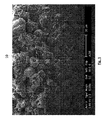

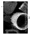
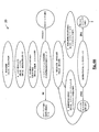


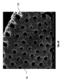


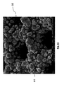

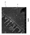
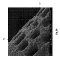
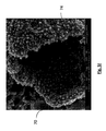


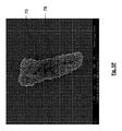
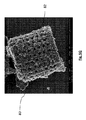


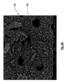


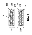


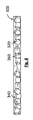

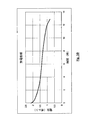

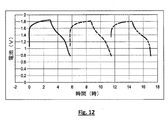

Classifications
-
- H—ELECTRICITY
- H01—ELECTRIC ELEMENTS
- H01M—PROCESSES OR MEANS, e.g. BATTERIES, FOR THE DIRECT CONVERSION OF CHEMICAL ENERGY INTO ELECTRICAL ENERGY
- H01M4/00—Electrodes
- H01M4/02—Electrodes composed of, or comprising, active material
- H01M4/13—Electrodes for accumulators with non-aqueous electrolyte, e.g. for lithium-accumulators; Processes of manufacture thereof
- H01M4/131—Electrodes based on mixed oxides or hydroxides, or on mixtures of oxides or hydroxides, e.g. LiCoOx
-
- H—ELECTRICITY
- H01—ELECTRIC ELEMENTS
- H01G—CAPACITORS; CAPACITORS, RECTIFIERS, DETECTORS, SWITCHING DEVICES, LIGHT-SENSITIVE OR TEMPERATURE-SENSITIVE DEVICES OF THE ELECTROLYTIC TYPE
- H01G11/00—Hybrid capacitors, i.e. capacitors having different positive and negative electrodes; Electric double-layer [EDL] capacitors; Processes for the manufacture thereof or of parts thereof
- H01G11/04—Hybrid capacitors
-
- H—ELECTRICITY
- H01—ELECTRIC ELEMENTS
- H01G—CAPACITORS; CAPACITORS, RECTIFIERS, DETECTORS, SWITCHING DEVICES, LIGHT-SENSITIVE OR TEMPERATURE-SENSITIVE DEVICES OF THE ELECTROLYTIC TYPE
- H01G11/00—Hybrid capacitors, i.e. capacitors having different positive and negative electrodes; Electric double-layer [EDL] capacitors; Processes for the manufacture thereof or of parts thereof
- H01G11/22—Electrodes
- H01G11/30—Electrodes characterised by their material
- H01G11/46—Metal oxides
-
- H—ELECTRICITY
- H01—ELECTRIC ELEMENTS
- H01G—CAPACITORS; CAPACITORS, RECTIFIERS, DETECTORS, SWITCHING DEVICES, LIGHT-SENSITIVE OR TEMPERATURE-SENSITIVE DEVICES OF THE ELECTROLYTIC TYPE
- H01G9/00—Electrolytic capacitors, rectifiers, detectors, switching devices, light-sensitive or temperature-sensitive devices; Processes of their manufacture
- H01G9/004—Details
- H01G9/04—Electrodes or formation of dielectric layers thereon
- H01G9/042—Electrodes or formation of dielectric layers thereon characterised by the material
-
- H—ELECTRICITY
- H01—ELECTRIC ELEMENTS
- H01M—PROCESSES OR MEANS, e.g. BATTERIES, FOR THE DIRECT CONVERSION OF CHEMICAL ENERGY INTO ELECTRICAL ENERGY
- H01M10/00—Secondary cells; Manufacture thereof
- H01M10/24—Alkaline accumulators
-
- H—ELECTRICITY
- H01—ELECTRIC ELEMENTS
- H01M—PROCESSES OR MEANS, e.g. BATTERIES, FOR THE DIRECT CONVERSION OF CHEMICAL ENERGY INTO ELECTRICAL ENERGY
- H01M10/00—Secondary cells; Manufacture thereof
- H01M10/36—Accumulators not provided for in groups H01M10/05-H01M10/34
-
- H—ELECTRICITY
- H01—ELECTRIC ELEMENTS
- H01M—PROCESSES OR MEANS, e.g. BATTERIES, FOR THE DIRECT CONVERSION OF CHEMICAL ENERGY INTO ELECTRICAL ENERGY
- H01M4/00—Electrodes
- H01M4/02—Electrodes composed of, or comprising, active material
- H01M4/24—Electrodes for alkaline accumulators
-
- H—ELECTRICITY
- H01—ELECTRIC ELEMENTS
- H01M—PROCESSES OR MEANS, e.g. BATTERIES, FOR THE DIRECT CONVERSION OF CHEMICAL ENERGY INTO ELECTRICAL ENERGY
- H01M4/00—Electrodes
- H01M4/02—Electrodes composed of, or comprising, active material
- H01M4/36—Selection of substances as active materials, active masses, active liquids
- H01M4/362—Composites
-
- H—ELECTRICITY
- H01—ELECTRIC ELEMENTS
- H01M—PROCESSES OR MEANS, e.g. BATTERIES, FOR THE DIRECT CONVERSION OF CHEMICAL ENERGY INTO ELECTRICAL ENERGY
- H01M4/00—Electrodes
- H01M4/02—Electrodes composed of, or comprising, active material
- H01M4/36—Selection of substances as active materials, active masses, active liquids
- H01M4/48—Selection of substances as active materials, active masses, active liquids of inorganic oxides or hydroxides
- H01M4/50—Selection of substances as active materials, active masses, active liquids of inorganic oxides or hydroxides of manganese
-
- H—ELECTRICITY
- H01—ELECTRIC ELEMENTS
- H01M—PROCESSES OR MEANS, e.g. BATTERIES, FOR THE DIRECT CONVERSION OF CHEMICAL ENERGY INTO ELECTRICAL ENERGY
- H01M4/00—Electrodes
- H01M4/02—Electrodes composed of, or comprising, active material
- H01M4/62—Selection of inactive substances as ingredients for active masses, e.g. binders, fillers
- H01M4/624—Electric conductive fillers
- H01M4/625—Carbon or graphite
-
- H—ELECTRICITY
- H01—ELECTRIC ELEMENTS
- H01M—PROCESSES OR MEANS, e.g. BATTERIES, FOR THE DIRECT CONVERSION OF CHEMICAL ENERGY INTO ELECTRICAL ENERGY
- H01M4/00—Electrodes
- H01M4/02—Electrodes composed of, or comprising, active material
- H01M2004/021—Physical characteristics, e.g. porosity, surface area
-
- H—ELECTRICITY
- H01—ELECTRIC ELEMENTS
- H01M—PROCESSES OR MEANS, e.g. BATTERIES, FOR THE DIRECT CONVERSION OF CHEMICAL ENERGY INTO ELECTRICAL ENERGY
- H01M4/00—Electrodes
- H01M4/02—Electrodes composed of, or comprising, active material
- H01M2004/026—Electrodes composed of, or comprising, active material characterised by the polarity
- H01M2004/028—Positive electrodes
-
- Y—GENERAL TAGGING OF NEW TECHNOLOGICAL DEVELOPMENTS; GENERAL TAGGING OF CROSS-SECTIONAL TECHNOLOGIES SPANNING OVER SEVERAL SECTIONS OF THE IPC; TECHNICAL SUBJECTS COVERED BY FORMER USPC CROSS-REFERENCE ART COLLECTIONS [XRACs] AND DIGESTS
- Y02—TECHNOLOGIES OR APPLICATIONS FOR MITIGATION OR ADAPTATION AGAINST CLIMATE CHANGE
- Y02E—REDUCTION OF GREENHOUSE GAS [GHG] EMISSIONS, RELATED TO ENERGY GENERATION, TRANSMISSION OR DISTRIBUTION
- Y02E60/00—Enabling technologies; Technologies with a potential or indirect contribution to GHG emissions mitigation
- Y02E60/10—Energy storage using batteries
-
- Y—GENERAL TAGGING OF NEW TECHNOLOGICAL DEVELOPMENTS; GENERAL TAGGING OF CROSS-SECTIONAL TECHNOLOGIES SPANNING OVER SEVERAL SECTIONS OF THE IPC; TECHNICAL SUBJECTS COVERED BY FORMER USPC CROSS-REFERENCE ART COLLECTIONS [XRACs] AND DIGESTS
- Y02—TECHNOLOGIES OR APPLICATIONS FOR MITIGATION OR ADAPTATION AGAINST CLIMATE CHANGE
- Y02E—REDUCTION OF GREENHOUSE GAS [GHG] EMISSIONS, RELATED TO ENERGY GENERATION, TRANSMISSION OR DISTRIBUTION
- Y02E60/00—Enabling technologies; Technologies with a potential or indirect contribution to GHG emissions mitigation
- Y02E60/30—Hydrogen technology
- Y02E60/50—Fuel cells
-
- Y—GENERAL TAGGING OF NEW TECHNOLOGICAL DEVELOPMENTS; GENERAL TAGGING OF CROSS-SECTIONAL TECHNOLOGIES SPANNING OVER SEVERAL SECTIONS OF THE IPC; TECHNICAL SUBJECTS COVERED BY FORMER USPC CROSS-REFERENCE ART COLLECTIONS [XRACs] AND DIGESTS
- Y02—TECHNOLOGIES OR APPLICATIONS FOR MITIGATION OR ADAPTATION AGAINST CLIMATE CHANGE
- Y02P—CLIMATE CHANGE MITIGATION TECHNOLOGIES IN THE PRODUCTION OR PROCESSING OF GOODS
- Y02P70/00—Climate change mitigation technologies in the production process for final industrial or consumer products
- Y02P70/50—Manufacturing or production processes characterised by the final manufactured product
Landscapes
- Chemical & Material Sciences (AREA)
- Chemical Kinetics & Catalysis (AREA)
- Electrochemistry (AREA)
- General Chemical & Material Sciences (AREA)
- Engineering & Computer Science (AREA)
- Power Engineering (AREA)
- Inorganic Chemistry (AREA)
- Materials Engineering (AREA)
- Microelectronics & Electronic Packaging (AREA)
- Manufacturing & Machinery (AREA)
- Composite Materials (AREA)
- Battery Electrode And Active Subsutance (AREA)
- Cell Separators (AREA)
- Secondary Cells (AREA)
- Electric Double-Layer Capacitors Or The Like (AREA)
- Detergent Compositions (AREA)
Abstract
エネルギー貯蔵デバイスは第一組の被殻を有するカソードを含み得て、第一組の被殻はマンガンの酸化物を有するナノ構造を含み得る。エネルギー貯蔵デバイスは第二組の被殻を有するアノードを含み得て、第二組の被殻は酸化亜鉛を有するナノ構造を含み得る。被殻は少なくとも一つの表面上に複数のナノ構造を有し得て、複数のナノ構造はマンガンの酸化物を含み得る。被殻は少なくとも一つの表面上に複数のナノ構造を有し得て、複数のナノ構造は酸化亜鉛を含み得る。エネルギー貯蔵デバイス用の電極は複数の被殻を含み、複数の被殻の各々は少なくとも一つの表面上に形成された複数のナノ構造を有し得る。 The energy storage device can include a cathode having a first set of shells, and the first set of shells can include nanostructures having an oxide of manganese. The energy storage device can include an anode having a second set of shells, and the second set of shells can include nanostructures having zinc oxide. The putamen can have a plurality of nanostructures on at least one surface, and the plurality of nanostructures can comprise an oxide of manganese. The putamen can have a plurality of nanostructures on at least one surface, and the plurality of nanostructures can comprise zinc oxide. An electrode for an energy storage device includes a plurality of shells, each of the plurality of shells having a plurality of nanostructures formed on at least one surface.
Description
[関連出願の相互参照]
本願は、2013年1月9日出願の「Diatomaceous Energy Storage Devices」との名称の米国仮出願第61/750757号及び2012年7月18日出願の「Diatomaceous Energy Storage Devices」との名称の米国仮出願第61/673149号の優先権を主張する2013年7月17日出願の「Diatomaceous Energy Storage Devices」との名刺用の米国特許出願第13/944211号の一部継続出願である2013年8月5日出願の「High Surface Area Nanoporous Energy Storage Devices」との名称の米国仮出願第61/862469号の優先権を主張する2014年1月22日出願の「Diatomaceous Energy Storage Devices」との名称の米国特許出願第14/161658号の一部継続出願である2016年6月22日出願の米国特許出願第14/745709号の優先権を主張し、その各々は全体が参照として本願に組み込まれる。
[Cross-reference of related applications]
This application is a US provisional application 61/750757 filed January 9, 2013 with the name “Diataceous Energy Storage Devices” and a US name of “Diataceous Energy Storage Devices” filed July 18, 2012. August 2013, which is a continuation-in-part of US Patent Application No. 13/944211, for business cards with “Diataceous Energy Storage Devices” filed July 17, 2013 claiming priority of application 61/673149 January 22, 2014 claiming priority from US Provisional Application No. 61/862469, entitled "High Surface Area Nanoporous Energy Storage Devices" Claims the priority of US patent application No. 14/745709 filed on June 22, 2016, which is a continuation-in-part of US patent application No. 14/161658, entitled “Diatomic Energy Storage Devices”; Each of which is incorporated herein by reference in its entirety.
本願は、エネルギー貯蔵デバイスに係り、特に珪藻の被殻を備えるエネルギー貯蔵デバイスに関する。 The present application relates to an energy storage device, and more particularly to an energy storage device comprising a diatom shell.
珪藻として、典型的に単細胞真核生物、例えば単細胞藻類が挙げられる。珪藻は自然界に豊富に存在し、淡水と海洋環境との両方において見つけることができる。一般的には、珪藻は、帯片を備える接続領域を介して互いに合わさった二つの殻を有する被殻に覆われている。珪藻土(珪藻岩としても知られている)は被殻の源である。珪藻土は、化石化した被殻を備え、濾過剤、塗料やプラスチックの充填材、吸着剤、猫トイレや研磨材等の多様な応用において使用可能である。 Diatoms typically include unicellular eukaryotes such as unicellular algae. Diatoms are abundant in nature and can be found in both freshwater and marine environments. In general, diatoms are covered with a shell that has two shells that are joined together via a connection region with strips. Diatomaceous earth (also known as diatomite) is the source of putamen. Diatomaceous earth has a fossilized shell and can be used in a variety of applications such as filter media, paint and plastic fillers, adsorbents, cat litters and abrasives.
被殻は、アルミナ、酸化鉄、酸化チタン、リン酸塩、石灰、ナトリウム及び/又はカリウムと共に顕著な量のシリカ(SiO2)を備えることが多い。被殻は典型的には電気絶縁性である。被殻は、多様な寸法、表面特徴、形状及び他の特質を備えるものであり得る。例えば、被殻は多様な形状を備え得て、円筒状、球形、円板状、角柱状が挙げられるがこれらの限定されるものではない。被殻は対称な形状又は非対称な形状を有する。珪藻は、被殻の形状及び/又は対称性に従って分類可能であり、例えば、放射相称の有無に基づいて被殻が分類される。被殻は、略1マイクロメートル未満から略数百マイクロメートルまでの範囲内の寸法を有し得る。被殻は、多様な多孔率も備え得て、多数の細孔やスリットを有する。被殻の細孔やスリットは形状、サイズ及び/又は密度が異なり得る。例えば、被殻は、略5nmから略1000nmまでの寸法を有する細孔を備え得る。 The shell is often provided with a significant amount of silica (SiO 2 ) along with alumina, iron oxide, titanium oxide, phosphate, lime, sodium and / or potassium. The putamen is typically electrically insulating. The putamen can have a variety of dimensions, surface features, shapes and other attributes. For example, the shell can be provided with various shapes, including, but not limited to, a cylindrical shape, a spherical shape, a disc shape, and a prismatic shape. The putamen has a symmetric shape or an asymmetric shape. Diatoms can be classified according to the shape and / or symmetry of the putamen, for example, the putamen are classified based on the presence or absence of a radiation synonym. The putamen can have dimensions in the range of less than about 1 micrometer to about several hundred micrometers. The shell can also have various porosities and has a large number of pores and slits. The pores and slits of the shell can vary in shape, size and / or density. For example, the shell can include pores having dimensions from about 5 nm to about 1000 nm.
被殻は、例えば、その被殻の寸法、被殻形状、多孔率、及び/又は物質組成に起因して顕著な機械的強度やせん断応力抵抗性を備え得る。 A shell can have significant mechanical strength and shear stress resistance due to, for example, its size, shell shape, porosity, and / or material composition.
電池(例えば、再充電可能な電池)、燃料電池、キャパシタ及び/又はスーパーキャパシタ(例えば、電気二重層キャパシタ(EDLC,electric double−layer capacitor)、疑似キャパシタ、対称キャパシタ)等のエネルギー貯蔵デバイスを、エネルギー貯蔵デバイスの少なくとも一つの層に埋め込まれた被殻を用いて製造し得る。被殻を、選択された形状、寸法、多孔率、物質、表面特徴及び/又は他の適切な被殻特質(均一又は実質的に均一であるか、又は異なるものであり得る)を有するように分類し得る。被殻は、被殻表面改質構造及び/又は物質を含み得る。エネルギー貯蔵デバイスは、電極、セパレータ及び/又は集電体等の層を含み得る。例えば、セパレータが第一電極と第二電極との間に位置し得て、第一集電体が第一電極に結合し得て、第二集電体が第二電極に結合し得る。セパレータと第一電極と第二電極とのうち少なくとも一つが被殻を含み得る。エネルギー貯蔵デバイスの少なくとも一部に被殻を含むことで、印刷技術(スクリーン印刷、ロールツーロール印刷、インクジェット印刷及び/又は他の適切な印刷プロセス等)を用いてエネルギー貯蔵デバイスを製造するのに役立ち得る。被殻はエネルギー貯蔵デバイス層の構造的支持を与え、また、エネルギー貯蔵デバイス層が製造及び/又は使用中における均一な又は実質的に均一な厚さを維持するのに役立ち得る。多孔質な被殻は、電子又はイオン種の妨げられていない又は実質的に妨げられていない流れを可能にする。表面構造又は物質を含む被殻は、層の導電性を増大させ得る。 Energy storage devices such as batteries (eg rechargeable batteries), fuel cells, capacitors and / or supercapacitors (eg electric double-layer capacitors (EDLCs), pseudocapacitors, symmetrical capacitors), It can be manufactured using a shell that is embedded in at least one layer of the energy storage device. The shell to have a selected shape, size, porosity, material, surface characteristics and / or other suitable shell characteristics (which may be uniform or substantially uniform or different) Can be classified. The shell may include a shell surface modification structure and / or material. The energy storage device may include layers such as electrodes, separators and / or current collectors. For example, the separator can be positioned between the first electrode and the second electrode, the first current collector can be coupled to the first electrode, and the second current collector can be coupled to the second electrode. At least one of the separator, the first electrode, and the second electrode may include a shell. Including the shell in at least a portion of the energy storage device to produce the energy storage device using printing techniques (such as screen printing, roll-to-roll printing, ink jet printing, and / or other suitable printing processes). Can be helpful. The putamen provides structural support for the energy storage device layer and can help the energy storage device layer maintain a uniform or substantially uniform thickness during manufacture and / or use. The porous hull allows unhindered or substantially unhindered flow of electrons or ionic species. A shell that includes a surface structure or material can increase the conductivity of the layer.
一部実施形態では、印刷エネルギー貯蔵デバイスは第一電極と、第二電極と、第一電極と第二電極との間のセパレータとを備える。第一電極と第二電極とセパレータとのうち少なくとも一つが被殻を含む。 In some embodiments, the printing energy storage device comprises a first electrode, a second electrode, and a separator between the first electrode and the second electrode. At least one of the first electrode, the second electrode, and the separator includes a shell.
一部実施形態では、セパレータが被殻を含む。一部実施形態では、第一電極が被殻を含む。一部実施形態では、セパレータ及び第一電極が被殻を含む。一部実施形態では、第二電極が被殻を含む。一部実施形態では、セパレータ及び第二電極が被殻を含む。一部実施形態では、第一電極及び第二電極が被殻を含む。一部実施形態では、セパレータ、第一電極及び第二電極が被殻を含む。 In some embodiments, the separator includes a shell. In some embodiments, the first electrode includes a shell. In some embodiments, the separator and the first electrode include a shell. In some embodiments, the second electrode includes a shell. In some embodiments, the separator and the second electrode include a shell. In some embodiments, the first electrode and the second electrode include a putamen. In some embodiments, the separator, the first electrode, and the second electrode include a shell.
一部実施形態では、被殻は実質的に均一な性質を有する。一部実施形態では、性質は形状、例えば、円筒、球、円板、又は角柱等を備える。一部実施形態では、性質は寸法、例えば、直径、長さ、最長軸等を備える。一部実施形態では、性質は多孔率を備える。一部実施形態では、性質は機械的強度を備える。 In some embodiments, the putamen has substantially uniform properties. In some embodiments, the property comprises a shape, such as a cylinder, a sphere, a disk, or a prism. In some embodiments, the property comprises a dimension, eg, diameter, length, longest axis, etc. In some embodiments, the property comprises porosity. In some embodiments, the property comprises mechanical strength.
一部実施形態では、被殻は表面改質構造を備える。一部実施形態では、表面改質構造は導電性物質を含む。一部実施形態では、導電性物質は銀とアルミニウムとタンタルと銅とリチウムとマグネシウムと黄銅とのうち少なくとも一種を含む。一部実施形態では、表面改質構造は酸化亜鉛(ZnO)を含む。一部実施形態では、表面改質構造は半導体を備える。一部実施形態では、半導体はシリコンとゲルマニウムとシリコンゲルマニウムとヒ化ガリウムとのうち少なくとも一種を含む。一部実施形態では、表面改質構造はナノワイヤと、ナノ粒子と、ロゼット形状を有する構造とのうち少なくとも一種を備える。一部実施形態では、表面改質構造は被殻の外部表面上に存在する。一部実施形態では、表面改質構造は被殻の内部表面上に存在する。一部実施形態では、表面改質構造は被殻の内部表面及び外部表面上に存在する。 In some embodiments, the putamen comprises a surface modified structure. In some embodiments, the surface modified structure includes a conductive material. In some embodiments, the conductive material includes at least one of silver, aluminum, tantalum, copper, lithium, magnesium, and brass. In some embodiments, the surface modified structure comprises zinc oxide (ZnO). In some embodiments, the surface modification structure comprises a semiconductor. In some embodiments, the semiconductor includes at least one of silicon, germanium, silicon germanium, and gallium arsenide. In some embodiments, the surface modified structure comprises at least one of a nanowire, a nanoparticle, and a structure having a rosette shape. In some embodiments, the surface modified structure is present on the outer surface of the putamen. In some embodiments, the surface modified structure is on the inner surface of the putamen. In some embodiments, the surface modified structure is present on the inner and outer surfaces of the shell.
一部実施形態では、被殻は表面改質物質を備える。一部実施形態では、表面改質物質は導電性物質を備える。一部実施形態では、表面改質物質は銀とアルミニウムとタンタルと銅とリチウムとマグネシウムと黄銅とのうち少なくとも一種を含む。一部実施形態では、表面改質物質はZnOを含む。一部実施形態では、表面改質物質は半導体を含む。一部実施形態では、半導体はシリコンとゲルマニウムとシリコンゲルマニウムとヒ化ガリウムとのうち少なくとも一種を含む。一部実施形態では、表面改質物質は被殻の外部表面上に存在する。一部実施形態では、表面改質物質は被殻の内部表面上に存在する。一部実施形態では、表面改質物質は被殻の内部表面及び外部表面上に存在する。 In some embodiments, the putamen comprises a surface modifying material. In some embodiments, the surface modifying material comprises a conductive material. In some embodiments, the surface modifying material includes at least one of silver, aluminum, tantalum, copper, lithium, magnesium, and brass. In some embodiments, the surface modifying material comprises ZnO. In some embodiments, the surface modifying material includes a semiconductor. In some embodiments, the semiconductor includes at least one of silicon, germanium, silicon germanium, and gallium arsenide. In some embodiments, the surface modifying material is present on the outer surface of the putamen. In some embodiments, the surface modifying material is present on the inner surface of the shell. In some embodiments, the surface modifying material is present on the inner and outer surfaces of the putamen.
一部実施形態では、第一電極は導電性充填材を備える。一部実施形態では、第二電極は導電性充填材を備える。一部実施形態では、第一電極及び第二電極は導電性充填材を備える。一部実施形態では、導電性充填材はグラファイト状炭素を備える。一部実施形態では、導電性充填材はグラフェンを備える。一部実施形態では、導電性充填材はカーボンナノチューブを備える。 In some embodiments, the first electrode comprises a conductive filler. In some embodiments, the second electrode comprises a conductive filler. In some embodiments, the first electrode and the second electrode comprise a conductive filler. In some embodiments, the conductive filler comprises graphitic carbon. In some embodiments, the conductive filler comprises graphene. In some embodiments, the conductive filler comprises carbon nanotubes.
一部実施形態では、第一電極は接着物質を備える。一部実施形態では、第二電極は接着物質を備える。一部実施形態では、第一電極及び第二電極は接着物質を備える。一部実施形態では、セパレータは接着物質を備える。一部実施形態では、第一電極及びセパレータは接着物質を備える。一部実施形態では、第二電極及びセパレータは接着物質を備える。一部実施形態では、第一電極、第二電極及びセパレータは接着物質を備える。一部実施形態では、接着物質はポリマーを備える。 In some embodiments, the first electrode comprises an adhesive material. In some embodiments, the second electrode comprises an adhesive material. In some embodiments, the first electrode and the second electrode comprise an adhesive material. In some embodiments, the separator comprises an adhesive material. In some embodiments, the first electrode and separator comprise an adhesive material. In some embodiments, the second electrode and separator comprise an adhesive material. In some embodiments, the first electrode, the second electrode, and the separator comprise an adhesive material. In some embodiments, the adhesive material comprises a polymer.
一部実施形態では、セパレータは電解質を備える。一部実施形態では、電解質はイオン液体と酸と塩基と塩とのうち少なくとも一種を備える。一部実施形態では、電解質は電解質ゲルを備える。 In some embodiments, the separator comprises an electrolyte. In some embodiments, the electrolyte comprises at least one of an ionic liquid, an acid, a base, and a salt. In some embodiments, the electrolyte comprises an electrolyte gel.
一部実施形態では、デバイスは、第一電極と電気的にやりとりする第一集電体を備える。一部実施形態では、デバイスは、第二電極と電気的にやりとりする第二集電体を備える。一部実施形態では、デバイスは、第一電極と電気的にやりとりする第一集電体と、第二電極と電気的にやりとりする第二集電体とを備える。 In some embodiments, the device comprises a first current collector in electrical communication with the first electrode. In some embodiments, the device comprises a second current collector that is in electrical communication with the second electrode. In some embodiments, the device comprises a first current collector in electrical communication with the first electrode and a second current collector in electrical communication with the second electrode.
一部実施形態では、印刷エネルギー貯蔵デバイスはキャパシタを備える。一部実施形態では、印刷エネルギー貯蔵デバイスはスーパーキャパシタを備える。一部実施形態では、印刷エネルギー貯蔵デバイスは電池を備える。 In some embodiments, the print energy storage device comprises a capacitor. In some embodiments, the print energy storage device comprises a supercapacitor. In some embodiments, the print energy storage device comprises a battery.
一部実施形態では、システムは、互いの上に積層させた複数の上記印刷エネルギー貯蔵デバイスを備える。一部実施形態では、電気デバイスは上記印刷エネルギー貯蔵デバイス又は上記システムを備える。 In some embodiments, the system comprises a plurality of the printing energy storage devices stacked on top of each other. In some embodiments, an electrical device comprises the printing energy storage device or the system.
一部実施形態では、印刷エネルギー貯蔵デバイス用の膜は被殻を備える。 In some embodiments, a film for a printing energy storage device comprises a shell.
一部実施形態では、被殻は実質的に均一な性質を有する。一部実施形態では、性質は形状、例えば、円筒、球、円板、又は角柱等を備える。一部実施形態では、性質は寸法、例えば、直径、長さ、最長軸等を備える。一部実施形態では、性質は多孔率を備える。一部実施形態では、性質は機械的強度を備える。 In some embodiments, the putamen has substantially uniform properties. In some embodiments, the property comprises a shape, such as a cylinder, a sphere, a disk, or a prism. In some embodiments, the property comprises a dimension, eg, diameter, length, longest axis, etc. In some embodiments, the property comprises porosity. In some embodiments, the property comprises mechanical strength.
一部実施形態では、被殻は表面改質構造を備える。一部実施形態では、表面改質構造は導電性物質を含む。一部実施形態では、導電性物質は銀とアルミニウムとタンタルと銅とリチウムとマグネシウムと黄銅とのうち少なくとも一種を含む。一部実施形態では、表面改質構造は酸化亜鉛(ZnO)を含む。一部実施形態では、表面改質構造は半導体を備える。一部実施形態では、半導体はシリコンとゲルマニウムとシリコンゲルマニウムとヒ化ガリウムとのうち少なくとも一種を含む。一部実施形態では、表面改質構造はナノワイヤと、ナノ粒子と、ロゼット形状を有する構造とのうち少なくとも一種を備える。一部実施形態では、表面改質構造は被殻の外部表面上に存在する。一部実施形態では、表面改質構造は被殻の内部表面上に存在する。一部実施形態では、表面改質構造は被殻の内部表面及び外部表面上に存在する。 In some embodiments, the putamen comprises a surface modified structure. In some embodiments, the surface modified structure includes a conductive material. In some embodiments, the conductive material includes at least one of silver, aluminum, tantalum, copper, lithium, magnesium, and brass. In some embodiments, the surface modified structure comprises zinc oxide (ZnO). In some embodiments, the surface modification structure comprises a semiconductor. In some embodiments, the semiconductor includes at least one of silicon, germanium, silicon germanium, and gallium arsenide. In some embodiments, the surface modified structure comprises at least one of a nanowire, a nanoparticle, and a structure having a rosette shape. In some embodiments, the surface modified structure is present on the outer surface of the putamen. In some embodiments, the surface modified structure is on the inner surface of the putamen. In some embodiments, the surface modified structure is present on the inner and outer surfaces of the shell.
一部実施形態では、被殻は表面改質物質を備える。一部実施形態では、表面改質物質は導電性物質を備える。一部実施形態では、表面改質物質は銀とアルミニウムとタンタルと銅とリチウムとマグネシウムと黄銅とのうち少なくとも一種を含む。一部実施形態では、表面改質物質はZnOを含む。一部実施形態では、表面改質物質は半導体を含む。一部実施形態では、半導体はシリコンとゲルマニウムとシリコンゲルマニウムとヒ化ガリウムとのうち少なくとも一種を含む。一部実施形態では、表面改質物質は被殻の外部表面上に存在する。一部実施形態では、表面改質物質は被殻の内部表面上に存在する。一部実施形態では、表面改質物質は被殻の内部表面及び外部表面上に存在する。 In some embodiments, the putamen comprises a surface modifying material. In some embodiments, the surface modifying material comprises a conductive material. In some embodiments, the surface modifying material includes at least one of silver, aluminum, tantalum, copper, lithium, magnesium, and brass. In some embodiments, the surface modifying material comprises ZnO. In some embodiments, the surface modifying material includes a semiconductor. In some embodiments, the semiconductor includes at least one of silicon, germanium, silicon germanium, and gallium arsenide. In some embodiments, the surface modifying material is present on the outer surface of the putamen. In some embodiments, the surface modifying material is present on the inner surface of the shell. In some embodiments, the surface modifying material is present on the inner and outer surfaces of the putamen.
一部実施形態では、膜は導電性充填材を更に備える。一部実施形態では、導電性充填材はグラファイト状炭素を備える。一部実施形態では、導電性充填材はグラフェンを備える。 In some embodiments, the membrane further comprises a conductive filler. In some embodiments, the conductive filler comprises graphitic carbon. In some embodiments, the conductive filler comprises graphene.
一部実施形態では、膜は接着物質を更に備える。一部実施形態では、接着物質はポリマーを備える。 In some embodiments, the membrane further comprises an adhesive material. In some embodiments, the adhesive material comprises a polymer.
一部実施形態では、膜は電解質を更に備える。一部実施形態では、電解質はイオン液体と酸と塩基と塩とのうち少なくとも一種を備える。一部実施形態では、電解質は電解質ゲルを備える。 In some embodiments, the membrane further comprises an electrolyte. In some embodiments, the electrolyte comprises at least one of an ionic liquid, an acid, a base, and a salt. In some embodiments, the electrolyte comprises an electrolyte gel.
一部実施形態では、エネルギー貯蔵デバイスは上記膜を備える。一部実施形態では、印刷エネルギー貯蔵デバイスはキャパシタを備える。一部実施形態では、印刷エネルギー貯蔵デバイスはスーパーキャパシタを備える。一部実施形態では、印刷エネルギー貯蔵デバイスは電池を備える。一部実施形態では、システムは、互いに上に積層させた複数の上記エネルギー貯蔵デバイスを備える。一部実施形態では、電気デバイスは上記印刷エネルギー貯蔵デバイス又は上記システムを備える。 In some embodiments, the energy storage device comprises the membrane. In some embodiments, the print energy storage device comprises a capacitor. In some embodiments, the print energy storage device comprises a supercapacitor. In some embodiments, the print energy storage device comprises a battery. In some embodiments, the system comprises a plurality of the above energy storage devices stacked on top of each other. In some embodiments, an electrical device comprises the printing energy storage device or the system.
一部実施形態では、印刷エネルギー貯蔵デバイスを製造する方法は、第一電極を形成することと、第二電極を形成することと、第一電極と第二電極との間にセパレータを形成することとを備える。第一電極と第二電極とセパレータとのうち少なくとも一つが被殻を含む。 In some embodiments, a method of manufacturing a printing energy storage device includes forming a first electrode, forming a second electrode, and forming a separator between the first electrode and the second electrode. With. At least one of the first electrode, the second electrode, and the separator includes a shell.
一部実施形態では、セパレータが被殻を含む。一部実施形態では、セパレータを形成することは、被殻の分散体を形成することを含む。一部実施形態では、セパレータを形成することは、セパレータをスクリーン印刷することを含む。一部実施形態では、セパレータを形成することは、被殻の膜を形成することを含む。一部実施形態では、セパレータを形成することは、セパレータを含む膜をロールツーロール印刷することを含む。 In some embodiments, the separator includes a shell. In some embodiments, forming the separator includes forming a shelled dispersion. In some embodiments, forming the separator includes screen printing the separator. In some embodiments, forming the separator includes forming a shelled membrane. In some embodiments, forming the separator includes roll-to-roll printing a film that includes the separator.
一部実施形態では、第一電極が被殻を含む。一部実施形態では、第一電極を形成することは、被殻の分散体を形成することを含む。一部実施形態では、第一電極を形成することは、第一電極をスクリーン印刷することを含む。一部実施形態では、第一電極を形成することは、被殻の膜を形成することを含む。一部実施形態では、第一電極を形成することは、第一電極を含む膜をロールツーロール印刷することを含む。 In some embodiments, the first electrode includes a shell. In some embodiments, forming the first electrode includes forming a shelled dispersion. In some embodiments, forming the first electrode includes screen printing the first electrode. In some embodiments, forming the first electrode includes forming a shelled film. In some embodiments, forming the first electrode includes roll-to-roll printing a film that includes the first electrode.
一部実施形態では、第二電極が被殻を含む。一部実施形態では、第二電極を形成することは、被殻の分散体を形成することを含む。一部実施形態では、第二電極を形成することは、第二電極をスクリーン印刷することを含む。一部実施形態では、第二電極を形成することは、被殻の膜を形成することを含む。一部実施形態では、第二電極を形成することは、第二電極を含む膜をロールツーロール印刷することを含む。 In some embodiments, the second electrode includes a shell. In some embodiments, forming the second electrode includes forming a shelled dispersion. In some embodiments, forming the second electrode includes screen printing the second electrode. In some embodiments, forming the second electrode includes forming a shelled film. In some embodiments, forming the second electrode includes roll-to-roll printing a film that includes the second electrode.
一部実施形態では、本方法は性質に従って被殻を分類することを更に備える。一部実施形態では、性質は、形状と寸法と物質と多孔率とのうち少なくとも一種を備える。 In some embodiments, the method further comprises classifying the putamen according to properties. In some embodiments, the property comprises at least one of shape, dimension, material, and porosity.
一部実施形態では、インクは溶液と、溶液中に分散した被殻とを備える。 In some embodiments, the ink comprises a solution and a shell put dispersed in the solution.
一部実施形態では、被殻は実質的に均一な性質を有する。一部実施形態では、性質は形状、例えば、円筒、球、円板、又は角柱等を備える。一部実施形態では、性質は寸法、例えば、直径、長さ、最長軸等を備える。一部実施形態では、性質は多孔率を備える。一部実施形態では、性質は機械的強度を備える。 In some embodiments, the putamen has substantially uniform properties. In some embodiments, the property comprises a shape, such as a cylinder, a sphere, a disk, or a prism. In some embodiments, the property comprises a dimension, eg, diameter, length, longest axis, etc. In some embodiments, the property comprises porosity. In some embodiments, the property comprises mechanical strength.
一部実施形態では、被殻は表面改質構造を備える。一部実施形態では、表面改質構造は導電性物質を含む。一部実施形態では、導電性物質は銀とアルミニウムとタンタルと銅とリチウムとマグネシウムと黄銅とのうち少なくとも一種を含む。一部実施形態では、表面改質構造は酸化亜鉛(ZnO)を含む。一部実施形態では、表面改質構造は半導体を備える。一部実施形態では、半導体はシリコンとゲルマニウムとシリコンゲルマニウムとヒ化ガリウムとのうち少なくとも一種を含む。一部実施形態では、表面改質構造はナノワイヤと、ナノ粒子と、ロゼット形状を有する構造とのうち少なくとも一種を備える。一部実施形態では、表面改質構造は被殻の外部表面上に存在する。一部実施形態では、表面改質構造は被殻の内部表面上に存在する。一部実施形態では、表面改質構造は被殻の内部表面及び外部表面上に存在する。 In some embodiments, the putamen comprises a surface modified structure. In some embodiments, the surface modified structure includes a conductive material. In some embodiments, the conductive material includes at least one of silver, aluminum, tantalum, copper, lithium, magnesium, and brass. In some embodiments, the surface modified structure comprises zinc oxide (ZnO). In some embodiments, the surface modification structure comprises a semiconductor. In some embodiments, the semiconductor includes at least one of silicon, germanium, silicon germanium, and gallium arsenide. In some embodiments, the surface modified structure comprises at least one of a nanowire, a nanoparticle, and a structure having a rosette shape. In some embodiments, the surface modified structure is present on the outer surface of the putamen. In some embodiments, the surface modified structure is on the inner surface of the putamen. In some embodiments, the surface modified structure is present on the inner and outer surfaces of the shell.
一部実施形態では、被殻は表面改質物質を備える。一部実施形態では、表面改質物質は導電性物質を備える。一部実施形態では、表面改質物質は銀とアルミニウムとタンタルと銅とリチウムとマグネシウムと黄銅とのうち少なくとも一種を含む。一部実施形態では、表面改質物質はZnOを含む。一部実施形態では、表面改質物質は半導体を含む。一部実施形態では、半導体はシリコンとゲルマニウムとシリコンゲルマニウムとヒ化ガリウムとのうち少なくとも一種を含む。一部実施形態では、表面改質物質は被殻の外部表面上に存在する。一部実施形態では、表面改質物質は被殻の内部表面上に存在する。一部実施形態では、表面改質物質は被殻の内部表面及び外部表面上に存在する。 In some embodiments, the putamen comprises a surface modifying material. In some embodiments, the surface modifying material comprises a conductive material. In some embodiments, the surface modifying material includes at least one of silver, aluminum, tantalum, copper, lithium, magnesium, and brass. In some embodiments, the surface modifying material comprises ZnO. In some embodiments, the surface modifying material includes a semiconductor. In some embodiments, the semiconductor includes at least one of silicon, germanium, silicon germanium, and gallium arsenide. In some embodiments, the surface modifying material is present on the outer surface of the putamen. In some embodiments, the surface modifying material is present on the inner surface of the shell. In some embodiments, the surface modifying material is present on the inner and outer surfaces of the putamen.
一部実施形態では、インクは導電性充填材を更に備える。一部実施形態では、導電性充填材はグラファイト状炭素を備える。一部実施形態では、導電性充填材はグラフェンを備える。 In some embodiments, the ink further comprises a conductive filler. In some embodiments, the conductive filler comprises graphitic carbon. In some embodiments, the conductive filler comprises graphene.
一部実施形態では、インクは接着物質を更に備える。一部実施形態では、接着物質はポリマーを備える。 In some embodiments, the ink further comprises an adhesive material. In some embodiments, the adhesive material comprises a polymer.
一部実施形態では、インクは電解質を更に備える。一部実施形態では、電解質はイオン液体と酸と塩基と塩とのうち少なくとも一種を備える。一部実施形態では、電解質は電解質ゲルを備える。 In some embodiments, the ink further comprises an electrolyte. In some embodiments, the electrolyte comprises at least one of an ionic liquid, an acid, a base, and a salt. In some embodiments, the electrolyte comprises an electrolyte gel.
一部実施形態では、デバイスは上記インクのうち少なくとも一種を備える。一部実施形態では、デバイスは印刷エネルギー貯蔵デバイスを備える。一部実施形態では、印刷エネルギー貯蔵デバイスはキャパシタを備える。一部実施形態では、印刷エネルギー貯蔵デバイスはスーパーキャパシタを備える。一部実施形態では、印刷エネルギー貯蔵デバイスは電池を備える。 In some embodiments, the device comprises at least one of the above inks. In some embodiments, the device comprises a printing energy storage device. In some embodiments, the print energy storage device comprises a capacitor. In some embodiments, the print energy storage device comprises a supercapacitor. In some embodiments, the print energy storage device comprises a battery.
珪藻被殻部分を抽出する方法は、複数の珪藻被殻部分を分散溶媒中に分散させることを備え得る。有機汚染物質と無機汚染物質との少なくとも一方を除去し得る。珪藻被殻部分を抽出する方法は、複数の珪藻被殻部分を表面活性剤中に分散させることを更に備え得て、表面活性剤が複数の珪藻被殻部分の凝集を低減する。本方法は、ディスクスタック遠心分離を用いて、少なくとも一つの共通の特性を有する複数の珪藻被殻部分を抽出することを備え得る。 The method for extracting a diatom shell portion may comprise dispersing a plurality of diatom shell portions in a dispersion solvent. At least one of organic and inorganic contaminants can be removed. The method of extracting a diatom shell portion may further comprise dispersing a plurality of diatom shell portions in a surfactant, wherein the surfactant reduces aggregation of the plurality of diatom shell portions. The method may comprise extracting a plurality of diatom shells having at least one common characteristic using disk stack centrifugation.
一部実施形態では、少なくとも一つの共通の特性は寸法と形状と物質と破損度とのうち少なくとも一種を含み得る。寸法は長さと直径とのうち少なくとも一方を含み得る。 In some embodiments, the at least one common characteristic may include at least one of dimension, shape, material, and degree of failure. The dimension can include at least one of a length and a diameter.
一部実施形態では、固体混合物が複数の珪藻被殻部分を備え得る。珪藻被殻部分を抽出する方法は、固体混合物の粒子寸法を低減することを備え得る。粒子寸法を低減することは、複数の珪藻被殻部分を分散溶媒中に分散させることの前であり得る。一部実施形態では、粒子寸法を低減することは、固体混合物をすり潰すことを備え得る。固体混合物をすり潰すことは、乳鉢及び乳棒と、ジャーミルと、岩石粉砕機とのうち少なくともひとつに固体混合物を適用することを含み得る。 In some embodiments, the solid mixture may comprise multiple diatom shell parts. The method of extracting the diatom shell portion can comprise reducing the particle size of the solid mixture. Reducing the particle size can be prior to dispersing a plurality of diatom shell parts in a dispersion solvent. In some embodiments, reducing the particle size may comprise grinding the solid mixture. Grinding the solid mixture may include applying the solid mixture to at least one of a mortar and pestle, jar mill, and rock crusher.
一部実施形態では、複数の珪藻被殻部分の最長被殻部分寸法よりも大きな最長成分寸法を有する固体混合物の成分を抽出し得る。固体混合物の成分を抽出することは、固体混合部を篩分けすることを備え得る。固体混合物を篩分けすることは、略15マイクロメートルから略25マイクロメートルまでのメッシュサイズを有する篩で固体混合物を処理することを備え得る。固体混合物を篩分けすることは、略10マイクロメートルから略25マイクロメートルまでのメッシュサイズを有する篩で固体混合物を処理することを備え得る。 In some embodiments, a component of a solid mixture having a longest component dimension that is greater than a longest shell part dimension of a plurality of diatom shell parts may be extracted. Extracting the components of the solid mixture may comprise sieving the solid mixing portion. Sifting the solid mixture may comprise treating the solid mixture with a sieve having a mesh size from about 15 micrometers to about 25 micrometers. Sifting the solid mixture may comprise treating the solid mixture with a sieve having a mesh size from about 10 micrometers to about 25 micrometers.
一部実施形態では、珪藻被殻部分を抽出する方法は、複数の珪藻被殻部分を分類して、より大きな最長寸法を有する第一珪藻被殻部分を第二珪藻被殻部分から分離することを備え得る。例えば、第一珪藻被殻部分は複数の破損していない珪藻被殻部分を備え得る。第二珪藻被殻部分は複数の破損した珪藻被殻部分を備え得る。 In some embodiments, the method of extracting a diatom shell portion classifies a plurality of diatom shell portions and separates a first diatom shell portion having a larger longest dimension from a second diatom shell portion. Can be provided. For example, the first diatom shell portion may comprise a plurality of undamaged diatom shell portions. The second diatom shell portion may comprise a plurality of broken diatom shell portions.
一部実施形態では、複数の珪藻被殻部分を分類することは、複数の珪藻被殻部分を濾過することを備え得る。濾過は、複数の珪藻被殻部分の凝集を阻害することを備え得る。一部実施形態では、複数の珪藻被殻部分の凝集を阻害することは、攪拌を備え得る。一部実施形態では、複数の珪藻被殻部分の凝集を阻害することは、振盪を備え得る。一部実施形態では、複数の珪藻被殻部分の凝集を阻害することは、バブリングを備え得る。 In some embodiments, classifying the plurality of diatom shell parts may comprise filtering the plurality of diatom shell parts. Filtration can comprise inhibiting aggregation of multiple diatom shell parts. In some embodiments, inhibiting aggregation of the plurality of diatom shell parts may comprise agitation. In some embodiments, inhibiting aggregation of the plurality of diatom shell parts may comprise shaking. In some embodiments, inhibiting aggregation of the plurality of diatom shell parts may comprise bubbling.
濾過は複数の珪藻被殻部分を篩にかけることを含み得る。例えば、篩は略5マイクロメートルから略10マイクロメートルまでのメッシュサイズ(例えば略7マイクロメートル)を有し得る。 Filtration can include sieving multiple diatom shell parts. For example, the sieve may have a mesh size from about 5 micrometers to about 10 micrometers (eg, about 7 micrometers).
一部実施形態では、珪藻被殻部分を抽出する方法は、洗浄された珪藻被殻部分を得ることを含み得る。洗浄された珪藻被殻部分を得ることは、有機汚染と無機汚染物質とのうち少なくとも一方を除去することの後に、複数の珪藻被殻部分を洗浄溶媒で洗浄することを備え得る。一部実施形態では、洗浄された珪藻被殻部分を得ることは、少なくとも一つの共通の特性を有する珪藻被殻部分を洗浄溶媒で洗浄することを備え得る。 In some embodiments, the method of extracting a diatom shell portion can include obtaining a washed diatom shell portion. Obtaining a washed diatom shell portion may comprise cleaning the plurality of diatom shell portions with a cleaning solvent after removing at least one of organic and inorganic contaminants. In some embodiments, obtaining a washed diatom shell portion may comprise cleaning the diatom shell portion having at least one common property with a cleaning solvent.
洗浄溶媒を除去し得る。例えば、洗浄溶媒を除去することは、有機汚染と無機汚染物質とのうち少なくとも一方を除去することの後に、複数の珪藻被殻部分を沈降させることを備え得る。例えば、洗浄溶媒を除去することは、少なくとも一つの共通の特性を有する複数の珪藻被殻部分を沈降させることを備え得る。複数の珪藻被殻部分を沈降させることは、遠心分離を備え得る。一部実施形態では、遠心分離は大規模処理に適した遠心分離を適用することを備え得る。一部実施形態では、遠心分離は、ディスクスタック遠心分離と、デカンタ遠心分離と管状ボウル遠心分離とのうち少なくとも一種を適用することを備え得る。 The washing solvent can be removed. For example, removing the cleaning solvent can comprise settling a plurality of diatom shell parts after removing at least one of organic and inorganic contaminants. For example, removing the cleaning solvent may comprise settling a plurality of diatom shell parts having at least one common property. Sedimenting a plurality of diatom shell parts may comprise centrifugation. In some embodiments, centrifugation may comprise applying a centrifugation suitable for large scale processing. In some embodiments, the centrifugation may comprise applying at least one of disk stack centrifugation, decanter centrifugation, and tubular bowl centrifugation.
一部実施形態では、分散溶媒と洗浄溶媒とのうち少なくとも一方は水を備え得る。 In some embodiments, at least one of the dispersion solvent and the washing solvent can comprise water.
一部実施形態では、複数の珪藻被殻部分を洗浄溶媒中に分散させることと、複数の珪藻被殻部分を表面活性剤中に分散させることとのうち少なくとも一方は、複数の珪藻被殻を超音波処理することを備え得る。 In some embodiments, at least one of dispersing a plurality of diatom shells in a cleaning solvent and dispersing a plurality of diatom shells in a surfactant comprises a plurality of diatom shells. Sonication can be provided.
表面活性剤はカチオン性表面活性剤を備え得る。例えば、カチオン性表面活性剤は、塩化ベンザルコニウム、臭化セトリモニウム、ラウリルメチルグルセス‐10ヒドロキシプロピルジモニウムクロリド、塩化ベンゼトニウム、ブロニドックス、ジメチルジオクタデシルアンモニウムクロリド、及び、水酸化テトラメチルアンモニウムのうち少なくとも一種を備え得る。 The surfactant can comprise a cationic surfactant. For example, cationic surfactants include benzalkonium chloride, cetrimonium bromide, lauryl methyl glutes-10 hydroxypropyl dimonium chloride, benzethonium chloride, bronidox, dimethyl dioctadecyl ammonium chloride, and tetramethyl ammonium hydroxide. At least one of them may be provided.
表面活性剤は非イオン性表面活性剤を備え得る。例えば、非イオン性表面活性剤は、セチルアルコール、ステアリルアルコール、セトステアリルアルコール、オレイルアルコール、ポリオキシエチレングリコールアルキルエーテル、オクタエチレングリコールモノドデシルエーテル、グルコシドアルキルエーテル、デシルグルコシド、ポリオキシエチレングリコールオクチルフェノールエーテル、オクチルフェノールエトキシレート(トリトンX‐100(登録商標))、ノノキシノール‐9、ラウリン酸グリセリル、ポリソルベート、及び、ポロキシマーのうち少なくとも一種を備え得る。 The surfactant can comprise a non-ionic surfactant. For example, nonionic surfactants include cetyl alcohol, stearyl alcohol, cetostearyl alcohol, oleyl alcohol, polyoxyethylene glycol alkyl ether, octaethylene glycol monododecyl ether, glucoside alkyl ether, decyl glucoside, polyoxyethylene glycol octyl phenol ether , Octylphenol ethoxylate (Triton X-100 (registered trademark)), nonoxynol-9, glyceryl laurate, polysorbate, and poloximer.
一部実施形態では、珪藻被殻部分を抽出する方法は、複数の珪藻被殻を添加成分中に分散させることを備え得る。複数の珪藻被殻を添加成分中に分散させることは、複数の珪藻被殻を表面活性剤中に分散させることの前であり得る。複数の珪藻被殻を添加成分中に分散させることは、複数の珪藻被殻を表面活性剤中に分散させることの後であり得る。複数の珪藻被殻を添加成分中に分散させることは、複数の珪藻被殻を表面活性剤中に分散させることと少なくとも部分的に同時であり得る。添加成分は塩化カリウムと塩化アンモニウムと水酸化アンモニウムと水酸化ナトリウムとのうち少なくとも一種を含み得る。 In some embodiments, the method of extracting the diatom shells may comprise dispersing a plurality of diatom shells in the additive component. Dispersing the plurality of diatom shells in the additive component can be prior to dispersing the plurality of diatom shells in the surfactant. Dispersing the plurality of diatom shells in the additive component may be after dispersing the plurality of diatom shells in the surfactant. Dispersing the plurality of diatom shells in the additive component can be at least partially simultaneous with dispersing the plurality of diatom shells in the surfactant. The additive component may include at least one of potassium chloride, ammonium chloride, ammonium hydroxide, and sodium hydroxide.
一部実施形態では、複数の珪藻被殻部分を分散させることは、略1重量パーセントから略5重量パーセントまでの複数の珪藻被殻部分を備える分散体を得ることを備え得る。 In some embodiments, dispersing the plurality of diatom shell portions can comprise obtaining a dispersion comprising from about 1 weight percent to about 5 weight percent of a plurality of diatom shell portions.
一部実施形態では、有機汚染物質を除去することは、漂白剤の存在下で複数の珪藻被殻部分を加熱することを備え得る。漂白剤は過酸化水素と硝酸とのうち少なくとも一方を含み得る。複数の珪藻被殻部分を加熱することは、略10体積パーセントから略20体積パーセントまでの範囲内の量の過酸化水を備える容器中で複数の珪藻被殻部分を加熱することを備え得る。複数の珪藻被殻部分を加熱することは、略5分から略15分までの持続期間にわたって複数の珪藻被殻部分を加熱することを備え得る。 In some embodiments, removing organic contaminants can comprise heating a plurality of diatom shell parts in the presence of a bleaching agent. The bleaching agent can include at least one of hydrogen peroxide and nitric acid. Heating the plurality of diatom shell parts may comprise heating the plurality of diatom shell parts in a container comprising an amount of peroxidized water in a range from about 10 volume percent to about 20 volume percent. Heating the plurality of diatom shells may comprise heating the plurality of diatom shells for a duration of about 5 minutes to about 15 minutes.
一部実施形態では、有機汚染物質を除去することは、複数の珪藻被殻部分をアニーリングすることを備え得る。一部実施形態では、無機汚染物質を除去することは、塩酸と硫酸とのうち少なくとも一方と複数の珪藻被殻部分を混ぜることを備え得る。塩酸と硫酸とのうち少なくとも一方と複数の珪藻被殻部分を混ぜることは、略15体積パーセントから略25体積パーセントまでの塩酸を備える溶液中に複数の珪藻被殻部分を混合することを含み得る。例えば、混合は略20分から略40分までの持続期間にわたり得る。 In some embodiments, removing organic contaminants can comprise annealing a plurality of diatom shell parts. In some embodiments, removing inorganic contaminants may comprise mixing at least one of hydrochloric acid and sulfuric acid and a plurality of diatom shell parts. Mixing the plurality of diatom shell parts with at least one of hydrochloric acid and sulfuric acid may include mixing the plurality of diatom shell parts in a solution comprising about 15 volume percent to about 25 volume percent hydrochloric acid. . For example, the mixing can be for a duration from about 20 minutes to about 40 minutes.
複数の珪藻被殻部分を抽出する方法は、ディスクスタック遠心分離を用いて、少なくとも一つの共通の特性を有する複数の珪藻被殻部分を抽出することを含み得る。 The method for extracting a plurality of diatom shell parts may comprise extracting a plurality of diatom shell parts having at least one common characteristic using disk stack centrifugation.
一部実施形態では、珪藻被殻部分を抽出する方法は、複数の珪藻被殻部分を分散溶媒中に分散させることを備え得る。一部実施形態では、本方法は、有機汚染物質と無機汚染物質とのうち少なくとも一方を除去することを備え得る。一部実施形態では、本方法は、複数の珪藻被殻部分を表面活性剤中に分散させることを備え得て、表面活性剤が複数の珪藻被殻部分の凝集を低減する。 In some embodiments, the method of extracting diatom shell parts may comprise dispersing a plurality of diatom shell parts in a dispersion solvent. In some embodiments, the method may comprise removing at least one of organic contaminants and inorganic contaminants. In some embodiments, the method may comprise dispersing a plurality of diatom shell parts in a surfactant, wherein the surfactant reduces aggregation of the plurality of diatom shell parts.
少なくとも一つの共通の特性は寸法と形状と物質と破損度とのうち少なくとも一種を含み得る。寸法は長さと直径とのうち少なくとも一方を含み得る。 The at least one common characteristic may include at least one of size, shape, material, and degree of failure. The dimension can include at least one of a length and a diameter.
一部実施形態では、固体混合物が複数の珪藻被殻部分を備え得る。珪藻被殻部分を抽出する方法は、固体混合物の粒子寸法を低減することを備え得る。固体混合物の粒子寸法を低減することは、複数の珪藻被殻部分を分散溶媒中に分散させることの前であり得る。一部実施形態では、粒子寸法を低減することは、固体混合物をすり潰すことを備え得る。固体混合物をすり潰すことは、乳鉢及び乳棒と、ジャーミルと、岩石粉砕機とのうち少なくともひとつに固体混合物を適用することを含み得る。 In some embodiments, the solid mixture may comprise multiple diatom shell parts. The method of extracting the diatom shell portion can comprise reducing the particle size of the solid mixture. Reducing the particle size of the solid mixture may be prior to dispersing the multiple diatom shell parts in the dispersion solvent. In some embodiments, reducing the particle size may comprise grinding the solid mixture. Grinding the solid mixture may include applying the solid mixture to at least one of a mortar and pestle, jar mill, and rock crusher.
一部実施形態では、複数の珪藻被殻部分の最長被殻部分寸法よりも大きな最長成分寸法を有する固体混合物の成分を抽出し得る。固体混合物の成分を抽出することは、固体混合部を篩分けすることを備え得る。固体混合物を篩分けすることは、略15マイクロメートルから略25マイクロメートルまでのメッシュサイズを有する篩で固体混合物を処理することを備え得る。固体混合物を篩分けすることは、略10マイクロメートルから略25マイクロメートルまでのメッシュサイズを有する篩で固体混合物を処理することを備え得る。 In some embodiments, a component of a solid mixture having a longest component dimension that is greater than a longest shell part dimension of a plurality of diatom shell parts may be extracted. Extracting the components of the solid mixture may comprise sieving the solid mixing portion. Sifting the solid mixture may comprise treating the solid mixture with a sieve having a mesh size from about 15 micrometers to about 25 micrometers. Sifting the solid mixture may comprise treating the solid mixture with a sieve having a mesh size from about 10 micrometers to about 25 micrometers.
一部実施形態では、珪藻被殻部分を抽出する方法は、複数の珪藻被殻部分を分類して、より大きな最長寸法を有する第一珪藻被殻部分を第二珪藻被殻部分から分離することを備え得る。例えば、第一珪藻被殻部分は複数の破損していない珪藻被殻部分を備え得る。第二珪藻被殻部分は複数の破損した珪藻被殻部分を備え得る。 In some embodiments, the method of extracting a diatom shell portion classifies a plurality of diatom shell portions and separates a first diatom shell portion having a larger longest dimension from a second diatom shell portion. Can be provided. For example, the first diatom shell portion may comprise a plurality of undamaged diatom shell portions. The second diatom shell portion may comprise a plurality of broken diatom shell portions.
一部実施形態では、複数の珪藻被殻部分を分類することは、複数の珪藻被殻部分を濾過することを備え得る。濾過は、複数の珪藻被殻部分の凝集を阻害することを備え得る。一部実施形態では、複数の珪藻被殻部分の凝集を阻害することは、攪拌を備え得る。一部実施形態では、複数の珪藻被殻部分の凝集を阻害することは、振盪を備え得る。一部実施形態では、複数の珪藻被殻部分の凝集を阻害することは、バブリングを備え得る。 In some embodiments, classifying the plurality of diatom shell parts may comprise filtering the plurality of diatom shell parts. Filtration can comprise inhibiting aggregation of multiple diatom shell parts. In some embodiments, inhibiting aggregation of the plurality of diatom shell parts may comprise agitation. In some embodiments, inhibiting aggregation of the plurality of diatom shell parts may comprise shaking. In some embodiments, inhibiting aggregation of the plurality of diatom shell parts may comprise bubbling.
濾過は複数の珪藻被殻部分を篩にかけることを含み得る。例えば、篩は略5マイクロメートルから略10マイクロメートルまでのメッシュサイズ(例えば略7マイクロメートル)を有し得る。 Filtration can include sieving multiple diatom shell parts. For example, the sieve may have a mesh size from about 5 micrometers to about 10 micrometers (eg, about 7 micrometers).
一部実施形態では、珪藻被殻部分を抽出する方法は、洗浄された珪藻被殻部分を得ることを含み得る。洗浄された珪藻被殻部分を得ることは、有機汚染と無機汚染物質とのうち少なくとも一方を除去することの後に、複数の珪藻被殻部分を洗浄溶媒で洗浄することを備え得る。一部実施形態では、洗浄された珪藻被殻部分を得ることは、少なくとも一つの共通の特性を有する珪藻被殻部分を洗浄溶媒で洗浄することを備え得る。 In some embodiments, the method of extracting a diatom shell portion can include obtaining a washed diatom shell portion. Obtaining a washed diatom shell portion may comprise cleaning the plurality of diatom shell portions with a cleaning solvent after removing at least one of organic and inorganic contaminants. In some embodiments, obtaining a washed diatom shell portion may comprise cleaning the diatom shell portion having at least one common property with a cleaning solvent.
洗浄溶媒を除去し得る。例えば、洗浄溶媒を除去することは、有機汚染と無機汚染物質とのうち少なくとも一方を除去することの後に、複数の珪藻被殻部分を沈降させることを備え得る。例えば、洗浄溶媒を除去することは、少なくとも一つの共通の特性を有する複数の珪藻被殻部分を沈降させることを備え得る。複数の珪藻被殻部分を沈降させることは、遠心分離を備え得る。一部実施形態では、遠心分離は大規模処理に適した遠心分離を適用することを備え得る。一部実施形態では、遠心分離は、ディスクスタック遠心分離と、デカンタ遠心分離と管状ボウル遠心分離とのうち少なくとも一種を適用することを備え得る。 The washing solvent can be removed. For example, removing the cleaning solvent can comprise settling a plurality of diatom shell parts after removing at least one of organic and inorganic contaminants. For example, removing the cleaning solvent may comprise settling a plurality of diatom shell parts having at least one common property. Sedimenting a plurality of diatom shell parts may comprise centrifugation. In some embodiments, centrifugation may comprise applying a centrifugation suitable for large scale processing. In some embodiments, the centrifugation may comprise applying at least one of disk stack centrifugation, decanter centrifugation, and tubular bowl centrifugation.
一部実施形態では、分散溶媒と洗浄溶媒とのうち少なくとも一方は水を備え得る。 In some embodiments, at least one of the dispersion solvent and the washing solvent can comprise water.
一部実施形態では、複数の珪藻被殻部分を洗浄溶媒中に分散させることと、複数の珪藻被殻部分を表面活性剤中に分散させることとのうち少なくとも一方は、複数の珪藻被殻を超音波処理することを備え得る。 In some embodiments, at least one of dispersing a plurality of diatom shells in a cleaning solvent and dispersing a plurality of diatom shells in a surfactant comprises a plurality of diatom shells. Sonication can be provided.
表面活性剤はカチオン性表面活性剤を備え得る。例えば、カチオン性表面活性剤は、塩化ベンザルコニウム、臭化セトリモニウム、ラウリルメチルグルセス‐10ヒドロキシプロピルジモニウムクロリド、塩化ベンゼトニウム、ブロニドックス、ジメチルジオクタデシルアンモニウムクロリド、及び、水酸化テトラメチルアンモニウムのうち少なくとも一種を備え得る。 The surfactant can comprise a cationic surfactant. For example, cationic surfactants include benzalkonium chloride, cetrimonium bromide, lauryl methyl glutes-10 hydroxypropyl dimonium chloride, benzethonium chloride, bronidox, dimethyl dioctadecyl ammonium chloride, and tetramethyl ammonium hydroxide. At least one of them may be provided.
表面活性剤は非イオン性表面活性剤を備え得る。例えば、非イオン性表面活性剤は、セチルアルコール、ステアリルアルコール、セトステアリルアルコール、オレイルアルコール、ポリオキシエチレングリコールアルキルエーテル、オクタエチレングリコールモノドデシルエーテル、グルコシドアルキルエーテル、デシルグルコシド、ポリオキシエチレングリコールオクチルフェノールエーテル、オクチルフェノールエトキシレート(トリトンX‐100(登録商標))、ノノキシノール‐9、ラウリン酸グリセリル、ポリソルベート、及び、ポロキシマーのうち少なくとも一種を備え得る。 The surfactant can comprise a non-ionic surfactant. For example, nonionic surfactants include cetyl alcohol, stearyl alcohol, cetostearyl alcohol, oleyl alcohol, polyoxyethylene glycol alkyl ether, octaethylene glycol monododecyl ether, glucoside alkyl ether, decyl glucoside, polyoxyethylene glycol octyl phenol ether , Octylphenol ethoxylate (Triton X-100 (registered trademark)), nonoxynol-9, glyceryl laurate, polysorbate, and poloximer.
一部実施形態では、珪藻被殻部分を抽出する方法は、複数の珪藻被殻を添加成分中に分散させることを備え得る。複数の珪藻被殻を添加成分中に分散させることは、複数の珪藻被殻を表面活性剤中に分散させることの前であり得る。複数の珪藻被殻を添加成分中に分散させることは、複数の珪藻被殻を表面活性剤中に分散させることの後であり得る。複数の珪藻被殻を添加成分中に分散させることは、複数の珪藻被殻を表面活性剤中に分散させることと少なくとも部分的に同時であり得る。添加成分は塩化カリウムと塩化アンモニウムと水酸化アンモニウムと水酸化ナトリウムとのうち少なくとも一種を含み得る。 In some embodiments, the method of extracting the diatom shells may comprise dispersing a plurality of diatom shells in the additive component. Dispersing the plurality of diatom shells in the additive component can be prior to dispersing the plurality of diatom shells in the surfactant. Dispersing the plurality of diatom shells in the additive component may be after dispersing the plurality of diatom shells in the surfactant. Dispersing the plurality of diatom shells in the additive component can be at least partially simultaneous with dispersing the plurality of diatom shells in the surfactant. The additive component may include at least one of potassium chloride, ammonium chloride, ammonium hydroxide, and sodium hydroxide.
一部実施形態では、複数の珪藻被殻部分を分散させることは、略1重量パーセントから略5重量パーセントまでの複数の珪藻被殻部分を備える分散体を得ることを備え得る。 In some embodiments, dispersing the plurality of diatom shell portions can comprise obtaining a dispersion comprising from about 1 weight percent to about 5 weight percent of a plurality of diatom shell portions.
一部実施形態では、有機汚染物質を除去することは、漂白剤の存在下で複数の珪藻被殻部分を加熱することを備え得る。漂白剤は過酸化水素と硝酸とのうち少なくとも一方を含み得る。複数の珪藻被殻部分を加熱することは、略10体積パーセントから略20体積パーセントまでの範囲内の量の過酸化水を備える容器中で複数の珪藻被殻部分を加熱することを備え得る。複数の珪藻被殻部分を加熱することは、略5分から略15分までの持続期間にわたって複数の珪藻被殻部分を加熱することを備え得る。 In some embodiments, removing organic contaminants can comprise heating a plurality of diatom shell parts in the presence of a bleaching agent. The bleaching agent can include at least one of hydrogen peroxide and nitric acid. Heating the plurality of diatom shell parts may comprise heating the plurality of diatom shell parts in a container comprising an amount of peroxidized water in a range from about 10 volume percent to about 20 volume percent. Heating the plurality of diatom shells may comprise heating the plurality of diatom shells for a duration of about 5 minutes to about 15 minutes.
一部実施形態では、有機汚染物質を除去することは、複数の珪藻被殻部分をアニーリングすることを備え得る。一部実施形態では、無機汚染物質を除去することは、塩酸と硫酸とのうち少なくとも一方と複数の珪藻被殻部分を混ぜることを備え得る。塩酸と硫酸とのうち少なくとも一方と複数の珪藻被殻部分を混ぜることは、略15体積パーセントから略25体積パーセントまでの塩酸を備える溶液中に複数の珪藻被殻部分を混合することを含み得る。例えば、混合は略20分から略40分までの持続期間にわたり得る。 In some embodiments, removing organic contaminants can comprise annealing a plurality of diatom shell parts. In some embodiments, removing inorganic contaminants may comprise mixing at least one of hydrochloric acid and sulfuric acid and a plurality of diatom shell parts. Mixing the plurality of diatom shell parts with at least one of hydrochloric acid and sulfuric acid may include mixing the plurality of diatom shell parts in a solution comprising about 15 volume percent to about 25 volume percent hydrochloric acid. . For example, the mixing can be for a duration from about 20 minutes to about 40 minutes.
珪藻被殻部分を抽出する方法は、表面活性剤で複数の珪藻被殻部分を分散させることを含み得て、表面活性剤が複数の珪藻被殻部分の凝集を低減する。 The method of extracting a diatom shell portion can include dispersing a plurality of diatom shell portions with a surfactant, wherein the surfactant reduces aggregation of the plurality of diatom shell portions.
珪藻被殻部分を抽出する方法は、ディスクスタック遠心分離を用いて、少なくとも一つの共通の特性を有する複数の珪藻被殻部分を抽出することを含み得る。一部実施形態では、珪藻被殻部分を抽出する方法は、複数の珪藻被殻部分を分散溶媒中に分散させることを備え得る。一部実施形態では、有機汚染物質と無機汚染物質とのうち少なくとも一方を除去し得る。 The method of extracting a diatom shell portion can include extracting a plurality of diatom shell portions having at least one common characteristic using disk stack centrifugation. In some embodiments, the method of extracting diatom shell parts may comprise dispersing a plurality of diatom shell parts in a dispersion solvent. In some embodiments, at least one of organic and inorganic contaminants may be removed.
一部実施形態では、少なくとも一つの共通の特性は寸法と形状と物質と破損度とのうち少なくとも一種を含み得る。寸法は長さと直径とのうち少なくとも一方を含み得る。 In some embodiments, the at least one common characteristic may include at least one of dimension, shape, material, and degree of failure. The dimension can include at least one of a length and a diameter.
一部実施形態では、固体混合物が複数の珪藻被殻部分を備え得る。珪藻被殻部分を抽出する方法は、固体混合物の粒子寸法を低減することを備え得る。固体混合物の粒子寸法を低減することは、複数の珪藻被殻部分を分散溶媒中に分散させることの前であり得る。一部実施形態では、粒子寸法を低減することは、固体混合物をすり潰すことを備え得る。固体混合物をすり潰すことは、乳鉢及び乳棒と、ジャーミルと、岩石粉砕機とのうち少なくともひとつに固体混合物を適用することを含み得る。 In some embodiments, the solid mixture may comprise multiple diatom shell parts. The method of extracting the diatom shell portion can comprise reducing the particle size of the solid mixture. Reducing the particle size of the solid mixture may be prior to dispersing the multiple diatom shell parts in the dispersion solvent. In some embodiments, reducing the particle size may comprise grinding the solid mixture. Grinding the solid mixture may include applying the solid mixture to at least one of a mortar and pestle, jar mill, and rock crusher.
一部実施形態では、複数の珪藻被殻部分の最長被殻部分寸法よりも大きな最長成分寸法を有する固体混合物の成分を抽出し得る。固体混合物の成分を抽出することは、固体混合部を篩分けすることを備え得る。固体混合物を篩分けすることは、略15マイクロメートルから略25マイクロメートルまでのメッシュサイズを有する篩で固体混合物を処理することを備え得る。固体混合物を篩分けすることは、略10マイクロメートルから略25マイクロメートルまでのメッシュサイズを有する篩で固体混合物を処理することを備え得る。 In some embodiments, a component of a solid mixture having a longest component dimension that is greater than a longest shell part dimension of a plurality of diatom shell parts may be extracted. Extracting the components of the solid mixture may comprise sieving the solid mixing portion. Sifting the solid mixture may comprise treating the solid mixture with a sieve having a mesh size from about 15 micrometers to about 25 micrometers. Sifting the solid mixture may comprise treating the solid mixture with a sieve having a mesh size from about 10 micrometers to about 25 micrometers.
一部実施形態では、珪藻被殻部分を抽出する方法は、複数の珪藻被殻部分を分類して、より大きな最長寸法を有する第一珪藻被殻部分を第二珪藻被殻部分から分離することを備え得る。例えば、第一珪藻被殻部分は複数の破損していない珪藻被殻部分を備え得る。第二珪藻被殻部分は複数の破損した珪藻被殻部分を備え得る。 In some embodiments, the method of extracting a diatom shell portion classifies a plurality of diatom shell portions and separates a first diatom shell portion having a larger longest dimension from a second diatom shell portion. Can be provided. For example, the first diatom shell portion may comprise a plurality of undamaged diatom shell portions. The second diatom shell portion may comprise a plurality of broken diatom shell portions.
一部実施形態では、複数の珪藻被殻部分を分類することは、複数の珪藻被殻部分を濾過することを備え得る。濾過は、複数の珪藻被殻部分の凝集を阻害することを備え得る。一部実施形態では、複数の珪藻被殻部分の凝集を阻害することは、攪拌を備え得る。一部実施形態では、複数の珪藻被殻部分の凝集を阻害することは、振盪を備え得る。一部実施形態では、複数の珪藻被殻部分の凝集を阻害することは、バブリングを備え得る。 In some embodiments, classifying the plurality of diatom shell parts may comprise filtering the plurality of diatom shell parts. Filtration can comprise inhibiting aggregation of multiple diatom shell parts. In some embodiments, inhibiting aggregation of the plurality of diatom shell parts may comprise agitation. In some embodiments, inhibiting aggregation of the plurality of diatom shell parts may comprise shaking. In some embodiments, inhibiting aggregation of the plurality of diatom shell parts may comprise bubbling.
濾過は複数の珪藻被殻部分を篩にかけることを含み得る。例えば、篩は略5マイクロメートルから略10マイクロメートルまでのメッシュサイズ(例えば略7マイクロメートル)を有し得る。 Filtration can include sieving multiple diatom shell parts. For example, the sieve may have a mesh size from about 5 micrometers to about 10 micrometers (eg, about 7 micrometers).
一部実施形態では、珪藻被殻部分を抽出する方法は、洗浄された珪藻被殻部分を得ることを含み得る。洗浄された珪藻被殻部分を得ることは、有機汚染と無機汚染物質とのうち少なくとも一方を除去することの後に、複数の珪藻被殻部分を洗浄溶媒で洗浄することを備え得る。一部実施形態では、洗浄された珪藻被殻部分を得ることは、少なくとも一つの共通の特性を有する珪藻被殻部分を洗浄溶媒で洗浄することを備え得る。 In some embodiments, the method of extracting a diatom shell portion can include obtaining a washed diatom shell portion. Obtaining a washed diatom shell portion may comprise cleaning the plurality of diatom shell portions with a cleaning solvent after removing at least one of organic and inorganic contaminants. In some embodiments, obtaining a washed diatom shell portion may comprise cleaning the diatom shell portion having at least one common property with a cleaning solvent.
洗浄溶媒を除去し得る。例えば、洗浄溶媒を除去することは、有機汚染と無機汚染物質とのうち少なくとも一方を除去することの後に、複数の珪藻被殻部分を沈降させることを備え得る。例えば、洗浄溶媒を除去することは、少なくとも一つの共通の特性を有する複数の珪藻被殻部分を沈降させることを備え得る。複数の珪藻被殻部分を沈降させることは、遠心分離を備え得る。一部実施形態では、遠心分離は大規模処理に適した遠心分離を適用することを備え得る。一部実施形態では、遠心分離は、ディスクスタック遠心分離と、デカンタ遠心分離と管状ボウル遠心分離とのうち少なくとも一種を適用することを備え得る。 The washing solvent can be removed. For example, removing the cleaning solvent can comprise settling a plurality of diatom shell parts after removing at least one of organic and inorganic contaminants. For example, removing the cleaning solvent may comprise settling a plurality of diatom shell parts having at least one common property. Sedimenting a plurality of diatom shell parts may comprise centrifugation. In some embodiments, centrifugation may comprise applying a centrifugation suitable for large scale processing. In some embodiments, the centrifugation may comprise applying at least one of disk stack centrifugation, decanter centrifugation, and tubular bowl centrifugation.
一部実施形態では、分散溶媒と洗浄溶媒とのうち少なくとも一方は水を備え得る。 In some embodiments, at least one of the dispersion solvent and the washing solvent can comprise water.
一部実施形態では、複数の珪藻被殻部分を洗浄溶媒中に分散させることと、複数の珪藻被殻部分を表面活性剤中に分散させることとのうち少なくとも一方は、複数の珪藻被殻を超音波処理することを備え得る。 In some embodiments, at least one of dispersing a plurality of diatom shells in a cleaning solvent and dispersing a plurality of diatom shells in a surfactant comprises a plurality of diatom shells. Sonication can be provided.
表面活性剤はカチオン性表面活性剤を備え得る。例えば、カチオン性表面活性剤は、塩化ベンザルコニウム、臭化セトリモニウム、ラウリルメチルグルセス‐10ヒドロキシプロピルジモニウムクロリド、塩化ベンゼトニウム、ブロニドックス、ジメチルジオクタデシルアンモニウムクロリド、及び、水酸化テトラメチルアンモニウムのうち少なくとも一種を備え得る。 The surfactant can comprise a cationic surfactant. For example, cationic surfactants include benzalkonium chloride, cetrimonium bromide, lauryl methyl glutes-10 hydroxypropyl dimonium chloride, benzethonium chloride, bronidox, dimethyl dioctadecyl ammonium chloride, and tetramethyl ammonium hydroxide. At least one of them may be provided.
表面活性剤は非イオン性表面活性剤を備え得る。例えば、非イオン性表面活性剤は、セチルアルコール、ステアリルアルコール、セトステアリルアルコール、オレイルアルコール、ポリオキシエチレングリコールアルキルエーテル、オクタエチレングリコールモノドデシルエーテル、グルコシドアルキルエーテル、デシルグルコシド、ポリオキシエチレングリコールオクチルフェノールエーテル、オクチルフェノールエトキシレート(トリトンX‐100(登録商標))、ノノキシノール‐9、ラウリン酸グリセリル、ポリソルベート、及び、ポロキシマーのうち少なくとも一種を備え得る。 The surfactant can comprise a non-ionic surfactant. For example, nonionic surfactants include cetyl alcohol, stearyl alcohol, cetostearyl alcohol, oleyl alcohol, polyoxyethylene glycol alkyl ether, octaethylene glycol monododecyl ether, glucoside alkyl ether, decyl glucoside, polyoxyethylene glycol octyl phenol ether , Octylphenol ethoxylate (Triton X-100 (registered trademark)), nonoxynol-9, glyceryl laurate, polysorbate, and poloximer.
一部実施形態では、珪藻被殻部分を抽出する方法は、複数の珪藻被殻を添加成分中に分散させることを備え得る。複数の珪藻被殻を添加成分中に分散させることは、複数の珪藻被殻を表面活性剤中に分散させることの前であり得る。複数の珪藻被殻を添加成分中に分散させることは、複数の珪藻被殻を表面活性剤中に分散させることの後であり得る。複数の珪藻被殻を添加成分中に分散させることは、複数の珪藻被殻を表面活性剤中に分散させることと少なくとも部分的に同時であり得る。添加成分は塩化カリウムと塩化アンモニウムと水酸化アンモニウムと水酸化ナトリウムとのうち少なくとも一種を含み得る。 In some embodiments, the method of extracting the diatom shells may comprise dispersing a plurality of diatom shells in the additive component. Dispersing the plurality of diatom shells in the additive component can be prior to dispersing the plurality of diatom shells in the surfactant. Dispersing the plurality of diatom shells in the additive component may be after dispersing the plurality of diatom shells in the surfactant. Dispersing the plurality of diatom shells in the additive component can be at least partially simultaneous with dispersing the plurality of diatom shells in the surfactant. The additive component may include at least one of potassium chloride, ammonium chloride, ammonium hydroxide, and sodium hydroxide.
一部実施形態では、複数の珪藻被殻部分を分散させることは、略1重量パーセントから略5重量パーセントまでの複数の珪藻被殻部分を備える分散体を得ることを備え得る。 In some embodiments, dispersing the plurality of diatom shell portions can comprise obtaining a dispersion comprising from about 1 weight percent to about 5 weight percent of a plurality of diatom shell portions.
一部実施形態では、有機汚染物質を除去することは、漂白剤の存在下で複数の珪藻被殻部分を加熱することを備え得る。漂白剤は過酸化水素と硝酸とのうち少なくとも一方を含み得る。複数の珪藻被殻部分を加熱することは、略10体積パーセントから略20体積パーセントまでの範囲内の量の過酸化水を備える容器中で複数の珪藻被殻部分を加熱することを備え得る。複数の珪藻被殻部分を加熱することは、略5分から略15分までの持続期間にわたって複数の珪藻被殻部分を加熱することを備え得る。 In some embodiments, removing organic contaminants can comprise heating a plurality of diatom shell parts in the presence of a bleaching agent. The bleaching agent can include at least one of hydrogen peroxide and nitric acid. Heating the plurality of diatom shell parts may comprise heating the plurality of diatom shell parts in a container comprising an amount of peroxidized water in a range from about 10 volume percent to about 20 volume percent. Heating the plurality of diatom shells may comprise heating the plurality of diatom shells for a duration of about 5 minutes to about 15 minutes.
一部実施形態では、有機汚染物質を除去することは、複数の珪藻被殻部分をアニーリングすることを備え得る。一部実施形態では、無機汚染物質を除去することは、塩酸と硫酸とのうち少なくとも一方と複数の珪藻被殻部分を混ぜることを備え得る。塩酸と硫酸とのうち少なくとも一方と複数の珪藻被殻部分を混ぜることは、略15体積パーセントから略25体積パーセントまでの塩酸を備える溶液中に複数の珪藻被殻部分を混合することを含み得る。例えば、混合は略20分から略40分までの持続期間にわたり得る。 In some embodiments, removing organic contaminants can comprise annealing a plurality of diatom shell parts. In some embodiments, removing inorganic contaminants may comprise mixing at least one of hydrochloric acid and sulfuric acid and a plurality of diatom shell parts. Mixing the plurality of diatom shell parts with at least one of hydrochloric acid and sulfuric acid may include mixing the plurality of diatom shell parts in a solution comprising about 15 volume percent to about 25 volume percent hydrochloric acid. . For example, the mixing can be for a duration from about 20 minutes to about 40 minutes.
珪藻被殻部分上に銀ナノ構造を形成する方法は、珪藻被殻部分の表面上に銀シード層を形成することを含み得る。本方法はシード層上にナノ構造を形成することを含み得る。 The method of forming silver nanostructures on the diatom shell portion can include forming a silver seed layer on the surface of the diatom shell portion. The method can include forming a nanostructure on the seed layer.
一部実施形態では、ナノ構造はコーティングとナノワイヤとナノプレートと稠密ナノ粒子アレイとナノベルトとナノディスクとのうち少なくとも一種を備え得る。一部実施形態では、ナノ構造は銀を備え得る。 In some embodiments, the nanostructure may comprise at least one of a coating, a nanowire, a nanoplate, a dense nanoparticle array, a nanobelt, and a nanodisk. In some embodiments, the nanostructure can comprise silver.
銀シード層を形成することは、第一銀寄与成分及び珪藻被殻部分に周期的加熱方式を適用することを備え得る。一部実施形態では、周期加熱方式を適用することは、周期的なマイクロ波パワーを適用することを備え得る。周期的マイクロ波パワーを適用することは、略100ワットと500ワットとの間でマイクロ波パワーを交替すること備え得る。例えば、交替はマイクロ波パワーを毎分交替することを備え得る。一部実施形態では、交替は略30分の持続期間にわたってマイクロ波パワーを交替することを備え得る。一部実施形態では、交替は略20分から略40分までの持続期間にわたってマイクロ波パワーを交替することを備え得る。 Forming the silver seed layer may comprise applying a periodic heating scheme to the first silver contributing component and the diatom shell. In some embodiments, applying a periodic heating scheme may comprise applying periodic microwave power. Applying periodic microwave power may comprise alternating the microwave power between approximately 100 watts and 500 watts. For example, alternation may comprise altering microwave power every minute. In some embodiments, the alternation may comprise altering the microwave power for a duration of approximately 30 minutes. In some embodiments, the alternation may comprise altering the microwave power for a duration of approximately 20 minutes to approximately 40 minutes.
一部実施形態では、銀シード層を形成することは、珪藻被殻部分をシード層溶液と混ぜることを備え得る。シード層溶液は第一銀寄与成分とシード層還元剤とを含み得る。例えば、シード層還元剤はシード層溶媒であり得る。一部実施形態では、シード層還元剤及びシート層溶媒はポリエチレングリコールを備え得る。 In some embodiments, forming the silver seed layer may comprise mixing the diatom shell portion with the seed layer solution. The seed layer solution may include a first silver contributing component and a seed layer reducing agent. For example, the seed layer reducing agent can be a seed layer solvent. In some embodiments, the seed layer reducing agent and the sheet layer solvent may comprise polyethylene glycol.
一部実施形態では、シード層溶液は第一銀寄与成分とシード層還元剤とシード層溶媒とを備え得る。 In some embodiments, the seed layer solution may comprise a first silver contributing component, a seed layer reducing agent, and a seed layer solvent.
銀シード層を形成することは、珪藻被殻部分をシード層溶液と混合することを備え得る。一部実施形態では、混合は超音波処理を備え得る。 Forming the silver seed layer may comprise mixing the diatom shell portion with the seed layer solution. In some embodiments, the mixing can comprise sonication.
一部実施形態では、シード層還元剤はN,N‐ジメチルホルムアミドを備え得て、第一銀寄与成分は硝酸銀を備え得て、シード層溶媒は水とポリビニルピロリドンとのうち少なくとも一方を備え得る。 In some embodiments, the seed layer reducing agent can comprise N, N-dimethylformamide, the first silver contributing component can comprise silver nitrate, and the seed layer solvent can comprise at least one of water and polyvinylpyrrolidone. .
ナノ構造を形成することは、珪藻被殻部分をナノ構造形成還元剤と混ぜることを備え得る。一部実施形態では、ナノ構造を形成することは、珪藻被殻部分をナノ構造形成還元剤と混ぜることの後に、珪藻被殻部分を加熱することを含み得る。例えば、加熱は、略120℃から略160℃までの或る温度に加熱することを備え得る。 Forming the nanostructure may comprise mixing the diatom shell portion with a nanostructure-forming reducing agent. In some embodiments, forming the nanostructure can include heating the diatom shell portion after mixing the diatom shell portion with a nanostructure-forming reducing agent. For example, the heating can comprise heating to a temperature from about 120 ° C. to about 160 ° C.
一部実施形態では、ナノ構造を形成することは、ナノ構造形成溶媒及び第二銀寄与成分を備える滴定溶液で珪藻被殻部分を滴定することを含み得る。一部実施形態では、ナノ構造を形成することは、滴定溶液で珪藻被殻部分を滴定することの後に混合することを備え得る。 In some embodiments, forming the nanostructure may include titrating a diatom shell portion with a titration solution comprising a nanostructure-forming solvent and a second silver contributing component. In some embodiments, forming the nanostructures may comprise mixing after titrating the diatom shell parts with a titration solution.
一部実施形態では、シード層還元剤とナノ構造形成還元剤とのうち少なくとも一方は、ヒドラジン、ホルムアルデヒド、グルコース、酒石酸ナトリウム、シュウ酸、ギ酸、アスコルビン酸、及び、エチレングリコールのうち少なくとも一種を備え得る。 In some embodiments, at least one of the seed layer reducing agent and the nanostructure-forming reducing agent comprises at least one of hydrazine, formaldehyde, glucose, sodium tartrate, oxalic acid, formic acid, ascorbic acid, and ethylene glycol. obtain.
一部実施形態では、第一銀寄与成分と第二銀寄与成分とのうち少なくとも一方が、銀塩と酸化銀とのうち少なくとも一方を備え得る。例えば、銀塩は、硝酸銀、アンモニア硝酸銀、塩化銀(AgCl)、シアン化銀(AgCN)、テトラフルオロホウ酸銀、六フッ化リン酸銀、及び、エチル硫酸銀のうち少なくとも一種を含み得る。 In some embodiments, at least one of the first silver contributing component and the second silver contributing component may comprise at least one of a silver salt and silver oxide. For example, the silver salt can include at least one of silver nitrate, silver ammonia nitrate, silver chloride (AgCl), silver cyanide (AgCN), silver tetrafluoroborate, silver hexafluorophosphate, and silver ethyl sulfate.
ナノ構造を形成することは、酸化物形成を低減する雰囲気におけるものとなり得る。例えば、雰囲気はアルゴン雰囲気を備え得る。 Forming nanostructures can be in an atmosphere that reduces oxide formation. For example, the atmosphere can comprise an argon atmosphere.
一部実施形態では、シード層溶媒とナノ構造形成溶媒とのうち少なくとも一方は、プロピレングリコール、水、メタノール、エタノール、1‐プロパノール、2‐プロパノール、1‐メトキシ‐2‐プロパノール、1‐ブタノール、2‐ブタノール、1‐ペンタノール、2‐ペンタノール、3‐ペンタノール、1‐ヘキサノール、2‐ヘキサノール、3‐ヘキサノール、オクタノール、1‐オクタノール、2‐オクタノール、3‐オクタノール、テトラヒドロフルフリルアルコール(THFA)、シクロヘキサノール、シクロペンタノール、テルピネオール、ブチルラクトン、メチルエチルエーテル、ジエチルエーテル、エチルプロピルエーテル、ポリエーテル、ジケトン、シクロヘキサノン、シクロペンタノン、シクロヘプタノン、シクロオクタノン、アセトン、ベンゾフェノン、アセチルアセトン、アセトフェノン、シクロプロパノン、イソホロン、メチルエチルケトン、エチルアセトン、アジピン酸ジメチル、プロピレングリコールモノメチルエーテルアセテート、グルタル酸ジメチル、コハク酸ジメチル、酢酸グリセリン、カルボン酸塩、炭酸プロピレン、グリセリン、ジオール、トリオール、テトラオール、ペンタオール、エチレングリコール、ジエチレングリコール、ポリエチレングリコール、プロピレングリコール、ジプロピレングリコール、グリコールエーテル、酢酸グリコールエーテル、1,4‐ブタンジオール、1,2‐ブタンジオール、2,3‐ブタンジオール、1,3‐プロパンジオール、1,4‐ブタンジオール、1,5‐ペンタンジオール、1,8‐オクタンジオール、1,2‐プロパンジオール、1,3‐ブタンジオール、1,2‐ペンタンジオール、エトヘキサジオール、p‐メンタン‐3,8‐ジオール、2‐メチル‐2,4‐ペンタンジオール、テトラメチル尿素、n‐メチルピロリドン、アセトニトリル、テトラヒドロフラン(THF)、ジメチルホルムアミド(DMF)、N‐メチルホルムアミド(NMF)、ジメチルスルホキシド(DMSO)、塩化チオニル、及び、塩化スルフリルのうち少なくとも一種を備え得る。 In some embodiments, at least one of the seed layer solvent and the nanostructure-forming solvent is propylene glycol, water, methanol, ethanol, 1-propanol, 2-propanol, 1-methoxy-2-propanol, 1-butanol, 2-butanol, 1-pentanol, 2-pentanol, 3-pentanol, 1-hexanol, 2-hexanol, 3-hexanol, octanol, 1-octanol, 2-octanol, 3-octanol, tetrahydrofurfuryl alcohol ( THFA), cyclohexanol, cyclopentanol, terpineol, butyl lactone, methyl ethyl ether, diethyl ether, ethyl propyl ether, polyether, diketone, cyclohexanone, cyclopentanone, cycloheptanone, cyclo Kutanone, acetone, benzophenone, acetylacetone, acetophenone, cyclopropanone, isophorone, methyl ethyl ketone, ethyl acetone, dimethyl adipate, propylene glycol monomethyl ether acetate, dimethyl glutarate, dimethyl succinate, glyceryl acetate, carboxylate, propylene carbonate, glycerin Diol, triol, tetraol, pentaol, ethylene glycol, diethylene glycol, polyethylene glycol, propylene glycol, dipropylene glycol, glycol ether, glycol acetate, 1,4-butanediol, 1,2-butanediol, 2,3 -Butanediol, 1,3-propanediol, 1,4-butanediol, 1,5-pentanediol, 1,8- Kutandiol, 1,2-propanediol, 1,3-butanediol, 1,2-pentanediol, ethohexadiol, p-menthane-3,8-diol, 2-methyl-2,4-pentanediol, tetramethyl At least one of urea, n-methylpyrrolidone, acetonitrile, tetrahydrofuran (THF), dimethylformamide (DMF), N-methylformamide (NMF), dimethylsulfoxide (DMSO), thionyl chloride, and sulfuryl chloride may be provided.
珪藻被殻部分は破損した珪藻被殻部分を備え得る。珪藻被殻部分は破損していない珪藻被殻部分を備え得る。一部実施形態では、珪藻被殻部分は珪藻被殻部分分離プロセスを介して得られ得る。例えば、プロセスは、表面活性剤を用いて複数の珪藻被殻部分の凝集を低減することと、ディスクスタック遠心分離を用いることとの少なくとも一方を備え得る。 The diatom shell portion may comprise a damaged diatom shell portion. The diatom shell portion may comprise an unbroken diatom shell portion. In some embodiments, the diatom shell portion can be obtained via a diatom shell portion separation process. For example, the process can comprise at least one of using a surfactant to reduce agglomeration of the multiple diatom shell parts and using disk stack centrifugation.
珪藻被殻部分上に酸化亜鉛ナノ構造を形成する方法は、珪藻被殻部分の表面上に酸化亜鉛シード層を形成することを含み得る。本方法は酸化亜鉛シード層上にナノ構造を形成することを備え得る。 The method of forming a zinc oxide nanostructure on a diatom shell portion can include forming a zinc oxide seed layer on the surface of the diatom shell portion. The method can comprise forming nanostructures on the zinc oxide seed layer.
一部実施形態では、ナノ構造はナノワイヤとナノプレートと稠密ナノ粒子アレイとナノベルトとナノディスクとのうち少なくとも一種を備え得る。一部実施形態では、ナノ構造は酸化亜鉛を備え得る。 In some embodiments, the nanostructure may comprise at least one of nanowires, nanoplates, dense nanoparticle arrays, nanobelts, and nanodisks. In some embodiments, the nanostructure can comprise zinc oxide.
酸化亜鉛シード層を形成することは、第一亜鉛寄与成分及び珪藻被殻部分を加熱することを備え得る。一部実施形態では、第一亜鉛寄与成分及び珪藻被殻部分を加熱することは、略175℃から略225℃までの範囲内の或る温度に加熱することを備え得る。 Forming the zinc oxide seed layer may comprise heating the first zinc contributing component and the diatom shell portion. In some embodiments, heating the first zinc-contributing component and the diatom shell portion can comprise heating to a temperature in the range of about 175 ° C to about 225 ° C.
一部実施形態では、ナノ構造を形成することは、第二亜鉛寄与成分を備えるナノ構造形成溶液の存在下で酸化亜鉛シード層を有する珪藻被殻部分に加熱方式を適用することを備え得る。加熱方式はナノ構造形成温度に加熱することを備え得る。例えば、ナノ構造形成温度は略80℃から略100℃までであり得る。一部実施形態では、加熱は略一時間から略三時間までの持続期間にわたり得る。一部実施形態では、加熱方式は周期的加熱手順を適用することを備え得る。例えば、周期的加熱手順は、全周期的加熱持続期間において、加熱持続期間にわたって酸化亜鉛シード層を有する珪藻被殻部分にマイクロ波加熱を適用し、次いで、冷却持続期間にわたってマイクロ波加熱をオフにすることを含み得る。一部実施形態では、加熱持続期間は略1分から略5分までであり得る。一部実施形態では、冷却持続期間は略30秒から略5分までであり得る。マイクロ波加熱を適用することは、略480ワットから略520ワットまでのマイクロ波パワー(略80ワットから略120ワットまでのマイクロ波パワー等)を適用することを含み得る。 In some embodiments, forming the nanostructure may comprise applying a heating scheme to the diatom shell portion having a zinc oxide seed layer in the presence of a nanostructure-forming solution comprising a second zinc contributing component. The heating regime may comprise heating to the nanostructure formation temperature. For example, the nanostructure formation temperature can be from about 80 ° C. to about 100 ° C. In some embodiments, the heating can be for a duration from about 1 hour to about 3 hours. In some embodiments, the heating regime may comprise applying a periodic heating procedure. For example, a cyclic heating procedure applies microwave heating to a diatom shell portion having a zinc oxide seed layer over the heating duration for the entire cyclic heating duration, and then turns off microwave heating for the cooling duration. Can include. In some embodiments, the heating duration can be from about 1 minute to about 5 minutes. In some embodiments, the cooling duration can be from about 30 seconds to about 5 minutes. Applying microwave heating may include applying microwave power from about 480 watts to about 520 watts (such as microwave power from about 80 watts to about 120 watts).
一部実施形態では、第一亜鉛寄与成分と第二亜鉛寄与成分とのうち少なくとも一方が、酢酸亜鉛、酢酸亜鉛水和物、硝酸亜鉛、硝酸亜鉛六水和物、塩化亜鉛、硫化亜鉛、及び、亜鉛酸ナトリウムのうちの少なくとも一種を備え得る。 In some embodiments, at least one of the first zinc contributing component and the second zinc contributing component is zinc acetate, zinc acetate hydrate, zinc nitrate, zinc nitrate hexahydrate, zinc chloride, zinc sulfide, and And at least one of sodium zincate.
一部実施形態では、ナノ構造形成溶液は塩基を含み得る。例えば、塩基は、水酸化ナトリウム、水酸化アンモニウム、水酸化カリウム、水酸化テトラメチルアンモニウム、水酸化リチウム、ヘキサメチレンテトラアミン、アンモニア溶液、炭酸ナトリウム、及び、エチレンジアミンのうち少なくとも一種を備え得る。 In some embodiments, the nanostructure forming solution may include a base. For example, the base may comprise at least one of sodium hydroxide, ammonium hydroxide, potassium hydroxide, tetramethylammonium hydroxide, lithium hydroxide, hexamethylenetetraamine, ammonia solution, sodium carbonate, and ethylenediamine.
一部実施形態では、ナノ構造を形成することは、添加成分を加えることを備え得る。添加成分は、トリブチルアミン、トリエチルアミン、トリエタノールアミン、ジイソプロピルアミン、リン酸アンモニウム、1,6‐ヘキサジアノール、トリエチルジエチノール、イソプロピルアミン、シクロヘキシルアミン、n‐ブチルアミン、塩化アンモニウム、ヘキサメチレンテトラアミン、エチレングリコール、エタノアミン、ポリビニルアルコール、ポリエチレングリコール、ドデシル硫酸ナトリウム、セチルトリメチルアンモニウムブロミド、及び、カルバミドのうち少なくとも一種を備え得る。 In some embodiments, forming the nanostructure can comprise adding an additive component. Additive components are tributylamine, triethylamine, triethanolamine, diisopropylamine, ammonium phosphate, 1,6-hexadianol, triethyldietinol, isopropylamine, cyclohexylamine, n-butylamine, ammonium chloride, hexamethylenetetraamine , Ethylene glycol, ethanolamine, polyvinyl alcohol, polyethylene glycol, sodium dodecyl sulfate, cetyltrimethylammonium bromide, and carbamide.
一部実施形態では、ナノ構造形成溶液と酸化亜鉛シード層形成溶液とのうち少なくとも一方は溶媒を備え得て、その溶媒は、プロピレングリコール、水、メタノール、エタノール、1‐プロパノール、2‐プロパノール、1‐メトキシ‐2‐プロパノール、1‐ブタノール、2‐ブタノール、1‐ペンタノール、2‐ペンタノール、3‐ペンタノール、1‐ヘキサノール、2‐ヘキサノール、3‐ヘキサノール、オクタノール、1‐オクタノール、2‐オクタノール、3‐オクタノール、テトラヒドロフルフリルアルコール(THFA)、シクロヘキサノール、シクロペンタノール、テルピネオール、ブチルラクトン、メチルエチルエーテル、ジエチルエーテル、エチルプロピルエーテル、ポリエーテル、ジケトン、シクロヘキサノン、シクロペンタノン、シクロヘプタノン、シクロオクタノン、アセトン、ベンゾフェノン、アセチルアセトン、アセトフェノン、シクロプロパノン、イソホロン、メチルエチルケトン、エチルアセトン、アジピン酸ジメチル、プロピレングリコールモノメチルエーテルアセテート、グルタル酸ジメチル、コハク酸ジメチル、酢酸グリセリン、カルボン酸塩、炭酸プロピレン、グリセリン、ジオール、トリオール、テトラオール、ペンタオール、エチレングリコール、ジエチレングリコール、ポリエチレングリコール、プロピレングリコール、ジプロピレングリコール、グリコールエーテル、酢酸グリコールエーテル、1,4‐ブタンジオール、1,2‐ブタンジオール、2,3‐ブタンジオール、1,3‐プロパンジオール、1,4‐ブタンジオール、1,5‐ペンタンジオール、1,8‐オクタンジオール、1,2‐プロパンジオール、1,3‐ブタンジオール、1,2‐ペンタンジオール、エトヘキサジオール、p‐メンタン‐3,8‐ジオール、2‐メチル‐2,4‐ペンタンジオール、テトラメチル尿素、n‐メチルピロリドン、アセトニトリル、テトラヒドロフラン(THF)、ジメチルホルムアミド(DMF)、N‐メチルホルムアミド(NMF)、ジメチルスルホキシド(DMSO)、塩化チオニル、及び、塩化スルフリルのうち少なくとも一種を備える。 In some embodiments, at least one of the nanostructure formation solution and the zinc oxide seed layer formation solution may comprise a solvent, the solvent being propylene glycol, water, methanol, ethanol, 1-propanol, 2-propanol, 1-methoxy-2-propanol, 1-butanol, 2-butanol, 1-pentanol, 2-pentanol, 3-pentanol, 1-hexanol, 2-hexanol, 3-hexanol, octanol, 1-octanol, 2 -Octanol, 3-octanol, tetrahydrofurfuryl alcohol (THFA), cyclohexanol, cyclopentanol, terpineol, butyl lactone, methyl ethyl ether, diethyl ether, ethyl propyl ether, polyether, diketone, cyclohexanone, siku Pentanone, cycloheptanone, cyclooctanone, acetone, benzophenone, acetylacetone, acetophenone, cyclopropanone, isophorone, methyl ethyl ketone, ethylacetone, dimethyl adipate, propylene glycol monomethyl ether acetate, dimethyl glutarate, dimethyl succinate, glycerine acetate, Carboxylate, propylene carbonate, glycerin, diol, triol, tetraol, pentaol, ethylene glycol, diethylene glycol, polyethylene glycol, propylene glycol, dipropylene glycol, glycol ether, glycol acetate, 1,4-butanediol, 1, 2-butanediol, 2,3-butanediol, 1,3-propanediol, 1,4-butanediol 1,5-pentanediol, 1,8-octanediol, 1,2-propanediol, 1,3-butanediol, 1,2-pentanediol, ethohexadiol, p-menthane-3,8-diol, 2-methyl-2,4-pentanediol, tetramethylurea, n-methylpyrrolidone, acetonitrile, tetrahydrofuran (THF), dimethylformamide (DMF), N-methylformamide (NMF), dimethylsulfoxide (DMSO), thionyl chloride, And at least one of sulfuryl chloride.
珪藻被殻部分は破損した珪藻被殻部分を備え得る。珪藻被殻部分は破損していない珪藻被殻部分を備え得る。一部実施形態では、珪藻被殻部分は珪藻被殻部分分離プロセスを介して得られ得る。例えば、プロセスは、表面活性剤を用いて複数の珪藻被殻部分の凝集を低減することと、ディスクスタック遠心分離を用いることとの少なくとも一方を備え得る。 The diatom shell portion may comprise a damaged diatom shell portion. The diatom shell portion may comprise an unbroken diatom shell portion. In some embodiments, the diatom shell portion can be obtained via a diatom shell portion separation process. For example, the process can comprise at least one of using a surfactant to reduce agglomeration of the multiple diatom shell parts and using disk stack centrifugation.
珪藻被殻部分上に炭素ナノ構造を形成する方法は、珪藻被殻部分の表面上に金属シード層を形成することを含み得る。本方法は、シード層上に炭素ナノ構造を形成することを含み得る。 The method of forming the carbon nanostructure on the diatom shell portion may include forming a metal seed layer on the surface of the diatom shell portion. The method can include forming a carbon nanostructure on the seed layer.
一部実施形態では、炭素ナノ構造はカーボンナノチューブを備え得る。カーボンナノチューブは単層カーボンナノチューブと多層カーボンナノチューブとのうち少なくとも一方を備え得る。 In some embodiments, the carbon nanostructure can comprise a carbon nanotube. The carbon nanotubes may include at least one of single-walled carbon nanotubes and multi-walled carbon nanotubes.
一部実施形態では、金属シード層を形成することは、珪藻被殻部分の表面をスプレーコーティングすることを備え得る。一部実施形態では、金属シード層を形成することは、金属を備える液体、金属を備える気体、及び金属を備える固体のうち少なくとも一つに珪藻被殻部分の表面を導入することを備え得る。 In some embodiments, forming the metal seed layer may comprise spray coating a surface of the diatom shell portion. In some embodiments, forming the metal seed layer may comprise introducing a surface of the diatom shell portion into at least one of a liquid comprising a metal, a gas comprising a metal, and a solid comprising a metal.
一部実施形態では、炭素ナノ構造を形成することは、化学気相堆積(CVD,chemical vapor deposition)を用いることを備え得る。炭素ナノ構造を形成することは、珪藻被殻部分をナノ構造形成炭素ガスに晒すことの後に、珪藻被殻部分をナノ構造形成還元ガスに晒すことを備え得る。炭素ナノ構造を形成することは、珪藻被殻部分をナノ構造形成炭素ガスに晒すことの前に、珪藻被殻部分をナノ構造形成還元ガスに晒すことを備え得る。一部実施形態では、炭素ナノ構造を形成することは、ナノ構造形成還元ガス及びナノ構造形成炭素ガスを備えるナノ構造形成ガス混合物に珪藻被殻部分を晒すことを備える。ナノ構造形成ガス混合物は中性ガスを含み得る。例えば、中性ガスはアルゴンであり得る。 In some embodiments, forming the carbon nanostructure may comprise using chemical vapor deposition (CVD). Forming the carbon nanostructure may comprise exposing the diatom shell portion to a nanostructure-forming reducing gas after exposing the diatom shell portion to the nanostructure-forming carbon gas. Forming the carbon nanostructure may comprise exposing the diatom shell portion to a nanostructure-forming reducing gas prior to exposing the diatom shell portion to the nanostructure-forming carbon gas. In some embodiments, forming the carbon nanostructure comprises exposing the diatom shell portion to a nanostructure-forming gas mixture comprising nanostructure-forming reducing gas and nanostructure-forming carbon gas. The nanostructure-forming gas mixture may include a neutral gas. For example, the neutral gas can be argon.
一部実施形態では、金属は、ニッケル、鉄、コバルト、コバルトモリブデン二金属、銅、金、銀、白金、パラジウム、マンガン、アルミニウム、マグネシウム、クロム、アンチモン、アルミニウム鉄モリブデン(Al/Fe/Mo)、ペンタカルボニル鉄(Fe(CO)5)、硝酸鉄(III)六水和物(Fe(NO3)3・6H2O)、塩化コバルト(II)六水和物(CoCl2・6H2O)、モリブデン酸アンモニウム四水和物((NH4)6Mo7O24・4H2O)、モリブデン(VI)二塩化二酸化物(MoO2Cl2)、及び、アルミナナノ粉末のうち少なくとも一種を備え得る。
In some embodiments, the metal is nickel, iron, cobalt, cobalt molybdenum bimetal, copper, gold, silver, platinum, palladium, manganese, aluminum, magnesium, chromium, antimony, aluminum iron molybdenum (Al / Fe / Mo). , iron pentacarbonyl (Fe (CO) 5), iron (III) nitrate hexahydrate (Fe (NO 3) 3 · 6H 2 O), cobalt (II)
一部実施形態では、ナノ構造形成還元ガスは、アンモニアと窒素と水素とのうち少なくとも一種を備え得る。ナノ構造形成炭素ガスが、アセチレン、エチレン、エタノール、メタン、酸化炭素、及びベンゼンのうち少なくとも一種を備え得る。 In some embodiments, the nanostructure-forming reducing gas may comprise at least one of ammonia, nitrogen, and hydrogen. The nanostructure-forming carbon gas may comprise at least one of acetylene, ethylene, ethanol, methane, carbon oxide, and benzene.
一部実施形態では、金属シード層を形成することは、銀シード層を形成することを備え得る。銀シード層を形成することは、珪藻被殻部分の表面上に銀ナノ構造を形成することを備え得る。 In some embodiments, forming the metal seed layer may comprise forming a silver seed layer. Forming the silver seed layer may comprise forming silver nanostructures on the surface of the diatom shell portion.
珪藻被殻部分は破損した珪藻被殻部分を備え得る。珪藻被殻部分は破損していない珪藻被殻部分を備え得る。一部実施形態では、珪藻被殻部分は、珪藻被殻部分分離プロセスを介して得られ得る。例えば、プロセスは、表面活性剤を用いて複数の珪藻被殻部分の凝集を低減することと、ディスクスタック遠心分離を用いることとのうち少なくとも一方を備え得る。 The diatom shell portion may comprise a damaged diatom shell portion. The diatom shell portion may comprise an unbroken diatom shell portion. In some embodiments, the diatom shell portion can be obtained via a diatom shell portion separation process. For example, the process may comprise at least one of reducing agglomeration of a plurality of diatom shells using a surfactant and using disk stack centrifugation.
銀インクを製造する方法は、紫外線感受性成分と、複数の珪藻被殻部分の表面上に銀ナノ構造を有する複数の珪藻被殻部分とを混ぜることを含み得て、その表面は複数の穿孔を備える。 A method of manufacturing a silver ink can include mixing an ultraviolet sensitive component and a plurality of diatom shell portions having silver nanostructures on a surface of the plurality of diatom shell portions, the surface having a plurality of perforations. Prepare.
一部実施形態では、銀インクを製造する方法は、複数の珪藻被殻部分の表面上に銀シード層を形成することを備え得る。一部実施形態では、本方法は、シード層上に銀ナノ構造を形成することを含み得る。 In some embodiments, a method for producing a silver ink may comprise forming a silver seed layer on the surface of a plurality of diatom shell parts. In some embodiments, the method can include forming silver nanostructures on the seed layer.
複数の珪藻被殻部分は複数の破損した珪藻被殻部分を含み得る。複数の珪藻被殻部分は複数の珪藻被殻フレークを含み得る。 The plurality of diatom shell portions may include a plurality of broken diatom shell portions. The plurality of diatom shell portions may include a plurality of diatom shell flakes.
一部実施形態では、銀インクは、硬化後に略5マイクロメートルから略15マイクロメートルまでの厚さを有する層として堆積可能なものである。一部実施形態では、複数の穿孔のうち少なくとも一つは略250ナノメートルから略350ナノメートルまでの直径を有する。一部実施形態では、銀ナノ構造は略10ナノメートルから略500ナノメートルまでの厚さを備え得る。銀インクは略50重量パーセントから略80重量パーセントまでの量の珪藻被殻を備え得る。 In some embodiments, the silver ink can be deposited as a layer having a thickness from about 5 micrometers to about 15 micrometers after curing. In some embodiments, at least one of the plurality of perforations has a diameter from about 250 nanometers to about 350 nanometers. In some embodiments, the silver nanostructure can comprise a thickness from about 10 nanometers to about 500 nanometers. The silver ink may comprise diatom shells in an amount from about 50 weight percent to about 80 weight percent.
銀シード層を形成することは、複数の穿孔内部の表面上に銀シード層を形成して、複数の銀シードでメッキされた穿孔を形成することを含み得る。銀シード層を形成することは、複数の珪藻被殻部分の実質的に全表面上に銀シード層を形成することを含み得る。 Forming the silver seed layer may include forming a silver seed layer on a surface within the plurality of perforations to form perforations plated with the plurality of silver seeds. Forming the silver seed layer may include forming a silver seed layer on substantially the entire surface of the plurality of diatom shell parts.
一部実施形態では、銀ナノ構造を形成することは、複数の穿孔内部の表面上に銀ナノ構造を形成して、複数の銀ナノ構造でメッキされた穿孔を形成することを備え得る。銀ナノ構造を形成することは、複数の珪藻被殻部分の実質的に全表面上に銀ナノ構造を形成することを備え得る。 In some embodiments, forming the silver nanostructure may comprise forming a silver nanostructure on a surface inside the plurality of perforations to form a perforation plated with the plurality of silver nanostructures. Forming the silver nanostructure may comprise forming the silver nanostructure on substantially the entire surface of the plurality of diatom shell parts.
一部実施形態では、紫外線感受性成分は、複数の穿孔の寸法よりも短い波長を有する光放射線に感受性を有し得る。紫外線感受性成分は、複数の銀シードでメッキされた穿孔と、複数の銀ナノ構造でメッキされた穿孔とのうち少なくとも一方の寸法よりも短い波長を有する光放射線に感受性を有し得る。 In some embodiments, the UV sensitive component may be sensitive to light radiation having a wavelength shorter than the dimensions of the plurality of perforations. The UV sensitive component may be sensitive to light radiation having a wavelength shorter than at least one dimension of perforations plated with a plurality of silver seeds and perforations plated with a plurality of silver nanostructures.
一部実施形態では、複数の珪藻被殻部分を紫外線感受性成分と混ぜることは、複数の珪藻被殻部分を光開始共力剤と混ぜることを含み得る。例えば、光開始共力剤は、エトキシ化ヘキサンジオールアクリレート、プロポキシ化ヘキサンジオールアクリレート、エトキシ化トリメチルプロパントリアクリレート、シアヌル酸トリアリル、及び、アクリル酸アミンのうち少なくとも一種を備え得る。 In some embodiments, mixing the plurality of diatom shells with the UV sensitive component can include mixing the plurality of diatom shells with a photoinitiator synergist. For example, the photoinitiator synergist may comprise at least one of ethoxylated hexanediol acrylate, propoxylated hexanediol acrylate, ethoxylated trimethylpropane triacrylate, triallyl cyanurate, and amine acrylate.
一部実施形態では、複数の珪藻被殻部分を紫外線感受性成分と混ぜることは、複数の珪藻被殻部分を光開始剤と混ぜることを含み得る。光開始剤は、2‐メチル‐1‐(4‐メチルチオ)フェニル‐2‐モルホリニル‐1‐プロパノンと、イソプロピルチオキサントンとのうち少なくとも一方を含み得る。 In some embodiments, mixing the plurality of diatom shell parts with the UV sensitive component may include mixing the plurality of diatom shell parts with a photoinitiator. The photoinitiator may comprise at least one of 2-methyl-1- (4-methylthio) phenyl-2-morpholinyl-1-propanone and isopropylthioxanthone.
一部実施形態では、複数の珪藻被殻部分を紫外線感受性成分と混ぜることは、複数の珪藻被殻部分を極性ビニルモノマーと混ぜることを含み得る。例えば、極性ビニルモノマーは、n‐ビニル‐ピロリドンと、n‐ビニルカプロラクタムとのうち少なくとも一方を含み得る。 In some embodiments, mixing the plurality of diatom shell parts with the UV sensitive component can include mixing the plurality of diatom shell parts with a polar vinyl monomer. For example, the polar vinyl monomer can include at least one of n-vinyl-pyrrolidone and n-vinylcaprolactam.
銀インクを製造する方法は、複数の珪藻被殻部分をレオロジー改質剤と混ぜることを備え得る。一部実施形態では、銀インクを製造する方法は、複数の珪藻被殻部分を架橋剤と混ぜることを備え得る。一部実施形態では、本方法は、複数の珪藻被殻部分をフロー及びレベル剤と混ぜること含み得る。一部実施形態では、本方法は、複数の珪藻被殻部分を、接着促進剤と湿潤剤と粘度低減剤とのうち少なくとも一種と混ぜることを含み得る。 A method for producing a silver ink may comprise mixing a plurality of diatom shell parts with a rheology modifier. In some embodiments, a method for producing a silver ink may comprise mixing a plurality of diatom shell parts with a crosslinker. In some embodiments, the method can include mixing a plurality of diatom shell parts with flow and leveling agents. In some embodiments, the method can include mixing a plurality of diatom shell parts with at least one of an adhesion promoter, a wetting agent, and a viscosity reducing agent.
銀ナノ構造は、コーティング、ナノワイヤ、ナノプレート、稠密ナノ粒子アレイ、ナノベルト、及びナノディスクとのうち少なくとも一種を含み得る。 The silver nanostructure may include at least one of a coating, a nanowire, a nanoplate, a dense nanoparticle array, a nanobelt, and a nanodisk.
一部実施形態では、銀シード層を形成することは、第一銀寄与成分及び複数の珪藻被殻部分に周期的加熱方式を適用することを備え得る。 In some embodiments, forming the silver seed layer may comprise applying a periodic heating scheme to the first silver contributing component and the plurality of diatom shell parts.
銀シード層を形成することは、珪藻被殻部分をシード層溶液と混ぜることを備え得る。例えば、シード層溶液は第一銀寄与成分及びシード層還元剤を備え得る。 Forming the silver seed layer may comprise mixing the diatom shell portion with the seed layer solution. For example, the seed layer solution may comprise a first silver contributing component and a seed layer reducing agent.
銀ナノ構造を形成することは、珪藻被殻部分をナノ構造形成還元剤と混ぜることを備え得る。一部実施形態では、銀ナノ構造を形成することは、珪藻被殻部分をナノ構造形成還元剤と混ぜることの後に珪藻被殻部分を加熱することを備え得る。一部実施形態では、ナノ構造を形成することは、ナノ構造形成溶媒及び第二銀寄与成分を備える滴定溶液で珪藻被殻部分を滴定することを備え得る。 Forming the silver nanostructure may comprise mixing the diatom shell portion with a nanostructure-forming reducing agent. In some embodiments, forming the silver nanostructure may comprise heating the diatom shell portion after mixing the diatom shell portion with a nanostructure-forming reducing agent. In some embodiments, forming the nanostructure may comprise titrating the diatom shell portion with a titration solution comprising a nanostructure-forming solvent and a second silver contributing component.
一部実施形態では、複数の珪藻被殻部分は、珪藻被殻部分分離プロセスを介して得られ得る。例えば、プロセスは、表面活性剤を用いて複数の珪藻被殻部分の凝集を低減することと、ディスクスタック遠心分離を用いることとのうち少なくとも一方を含み得る。 In some embodiments, a plurality of diatom shell parts can be obtained via a diatom shell part separation process. For example, the process can include at least one of reducing agglomeration of the multiple diatom shells using a surfactant and using disk stack centrifugation.
導電性銀インクは紫外線感受性成分を含み得る。導電性インクは、複数の珪藻被殻部分の表面上に銀ナノ構造を有する複数の珪藻被殻部分を含み得て、その表面が複数の穿孔を備える。 The conductive silver ink can include an ultraviolet sensitive component. The conductive ink may include a plurality of diatom shell parts having silver nanostructures on a surface of the plurality of diatom shell parts, the surface comprising a plurality of perforations.
複数の珪藻被殻部分は複数の破損した珪藻被殻部分を含み得る。複数の珪藻被殻部分は複数の珪藻被殻フレークを含み得る。 The plurality of diatom shell portions may include a plurality of broken diatom shell portions. The plurality of diatom shell portions may include a plurality of diatom shell flakes.
一部実施形態では、銀インクは、(例えば、硬化後に)略5マイクロメートルから略15マイクロメートルまでの厚さを有する層として堆積可能なものである。一部実施形態では、複数の穿孔のうち少なくとも一つは略250ナノメートルから略350ナノメートルまでの直径を有する。一部実施形態では、銀ナノ構造は略10ナノメートルから略500ナノメートルまでの厚さを備え得る。銀インクは略50重量パーセントから略80重量パーセントまでの範囲内の量の珪藻被殻を備え得る。 In some embodiments, the silver ink can be deposited as a layer having a thickness from about 5 micrometers to about 15 micrometers (eg, after curing). In some embodiments, at least one of the plurality of perforations has a diameter from about 250 nanometers to about 350 nanometers. In some embodiments, the silver nanostructure can comprise a thickness from about 10 nanometers to about 500 nanometers. The silver ink may comprise an amount of diatom hull in the range of about 50 weight percent to about 80 weight percent.
一部実施形態では、複数の穿孔のうち少なくとも一つは、銀ナノ構造を有する表面を備え得る。 In some embodiments, at least one of the plurality of perforations may comprise a surface having silver nanostructures.
一部実施形態では、複数の穿孔のうち少なくとも一つは、銀シード層を有する表面を備える。一部実施形態では、複数の珪藻被殻部分の実質的に全表面が銀ナノ構造を備え得る。 In some embodiments, at least one of the plurality of perforations comprises a surface having a silver seed layer. In some embodiments, substantially the entire surface of the plurality of diatom shell portions can comprise silver nanostructures.
一部実施形態では、紫外線感受性成分は、複数の穿孔の寸法よりも短い波長を有する光放射線に感受性を有し得る。 In some embodiments, the UV sensitive component may be sensitive to light radiation having a wavelength shorter than the dimensions of the plurality of perforations.
一部実施形態では、導電性銀インクは紫外線によって硬化可能なものであり得る。一部実施形態では、複数の穿孔は、紫外線が通過するのに十分な寸法を有し得る。導電性銀インクは、(例えば、硬化後に)略5マイクロメートルから略15マイクロメートルまでの厚さを有する層として堆積可能なものであり得る。 In some embodiments, the conductive silver ink can be curable by ultraviolet light. In some embodiments, the plurality of perforations may have a dimension sufficient for ultraviolet light to pass through. The conductive silver ink can be depositable as a layer having a thickness from about 5 micrometers to about 15 micrometers (eg, after curing).
一部実施形態では、導電性銀インク熱硬化性であり得る。 In some embodiments, the conductive silver ink can be thermoset.
一部実施形態では、紫外線感受性成分は光開始共力剤を含み得る。例えば、光開始共力剤は、エトキシ化ヘキサンジオールアクリレート、プロポキシ化ヘキサンジオールアクリレート、エトキシ化トリメチルプロパントリアクリレート、シアヌル酸トリアリル、及び、アクリル酸アミンのうち少なくとも一種を備え得る。 In some embodiments, the UV sensitive component may include a photoinitiator synergist. For example, the photoinitiator synergist may comprise at least one of ethoxylated hexanediol acrylate, propoxylated hexanediol acrylate, ethoxylated trimethylpropane triacrylate, triallyl cyanurate, and amine acrylate.
紫外線感受性成分は光開始剤を含み得る。光開始剤は、2‐メチル‐1‐(4‐メチルチオ)フェニル‐2‐モルホリニル‐1‐プロパノンと、イソプロピルチオキサントンとのうち少なくとも一方を含み得る。 The UV sensitive component can include a photoinitiator. The photoinitiator may comprise at least one of 2-methyl-1- (4-methylthio) phenyl-2-morpholinyl-1-propanone and isopropylthioxanthone.
一部実施形態では、紫外線感受性成分は極性ビニルモノマーを含み得る。例えば、極性ビニルモノマーは、n‐ビニル‐ピロリドンと、n‐ビニルカプロラクタムとのうち少なくとも一方を含み得る。 In some embodiments, the UV sensitive component can include a polar vinyl monomer. For example, the polar vinyl monomer can include at least one of n-vinyl-pyrrolidone and n-vinylcaprolactam.
導電性銀インクは、レオロジー改質剤、架橋剤、フロー及びレベル剤、接着促進剤、湿潤剤、粘度低減剤とのうち少なくとも一種を含み得る。一部実施形態では、銀ナノ構造は、コーティング、ナノワイヤ、ナノプレート、稠密ナノ粒子アレイ、ナノベルト、ナノディスクとのうち少なくとも一種を備え得る。 The conductive silver ink may include at least one of a rheology modifier, a crosslinking agent, a flow and level agent, an adhesion promoter, a wetting agent, and a viscosity reducing agent. In some embodiments, the silver nanostructure may comprise at least one of a coating, nanowire, nanoplate, dense nanoparticle array, nanobelt, nanodisk.
銀フィルムを製造する方法は、紫外性感受性成分と、複数の珪藻被殻部分の表面上に銀ナノ構造を有する複数の珪藻被殻部分とを備える混合物を硬化させることを含み得て、その表面が複数の穿孔を備える。 A method of manufacturing a silver film can include curing a mixture comprising an ultraviolet sensitive component and a plurality of diatom shell parts having silver nanostructures on a surface of the plurality of diatom shell parts, Comprises a plurality of perforations.
一部実施形態では、銀フィルムを製造する方法は、複数の珪藻被殻部分の表面上に銀シード層を形成することを備え得る。一部実施形態では、本方法は、シード層上に銀ナノ構造を形成することを備え得る。一部実施形態では、本方法は、複数の珪藻被殻部分を紫外線感受性成分と混ぜて、銀インクを形成することを含み得る。 In some embodiments, a method of manufacturing a silver film may comprise forming a silver seed layer on the surface of a plurality of diatom shell parts. In some embodiments, the method may comprise forming silver nanostructures on the seed layer. In some embodiments, the method can include mixing a plurality of diatom shell parts with an ultraviolet sensitive component to form a silver ink.
複数の珪藻被殻部分は複数の破損した珪藻被殻部分を備え得る。複数の珪藻被殻部分は複数の珪藻被殻フレークを備え得る。 The plurality of diatom shell parts may comprise a plurality of broken diatom shell parts. The plurality of diatom shell portions may comprise a plurality of diatom shell flakes.
一部実施形態では、銀インクは、(例えば、硬化後に)略5マイクロメートルから略15マイクロメートルまでの厚さを有する層として堆積可能なものである。一部実施形態では、複数の穿孔のうち少なくとも一つは略250ナノメートルから略350ナノメートルまでの直径を有する。一部実施形態では、銀ナノ構造は略10ナノメートルから略500ナノメートルまでの厚さを備え得る。銀インクは略50重量パーセントから略80重量パーセントまでの範囲内の量の珪藻被殻を備え得る。 In some embodiments, the silver ink can be deposited as a layer having a thickness from about 5 micrometers to about 15 micrometers (eg, after curing). In some embodiments, at least one of the plurality of perforations has a diameter from about 250 nanometers to about 350 nanometers. In some embodiments, the silver nanostructure can comprise a thickness from about 10 nanometers to about 500 nanometers. The silver ink may comprise an amount of diatom hull in the range of about 50 weight percent to about 80 weight percent.
銀シード層を形成することは、複数の穿孔内部の表面上に銀シード層を形成して、複数の銀シードでメッキされた穿孔を形成することを備え得る。銀シード層を形成することは、複数の珪藻被殻部分の実質的に全表面上に銀シード層を形成することを備え得る。 Forming the silver seed layer may comprise forming a silver seed layer on a surface inside the plurality of perforations to form perforations plated with the plurality of silver seeds. Forming the silver seed layer may comprise forming a silver seed layer on substantially the entire surface of the plurality of diatom shell parts.
銀ナノ構造を形成することは、複数の穿孔内部の表面上に銀ナノ構造を形成して、複数の銀ナノ構造でメッキされた穿孔を形成することを備え得る。銀ナノ構造を形成することは、複数の珪藻被殻部分の実質的に全表面上に銀ナノ構造を形成することを備え得る。 Forming silver nanostructures may comprise forming silver nanostructures on surfaces within the plurality of perforations to form perforations plated with the plurality of silver nanostructures. Forming the silver nanostructure may comprise forming the silver nanostructure on substantially the entire surface of the plurality of diatom shell parts.
一部実施形態では、混合物を硬化させることは、複数の穿孔の寸法よりも短い波長を有する紫外線に混合物を晒すことを備え得る。一部実施形態では、混合物を硬化させることは、複数の銀シードでメッキされた穿孔と、複数の銀ナノ構造でメッキされた穿孔とのうち少なくとも一方の寸法よりも短い波長を有する紫外線に混合物を晒すことを備え得る。 In some embodiments, curing the mixture may comprise exposing the mixture to ultraviolet light having a wavelength that is shorter than a dimension of the plurality of perforations. In some embodiments, curing the mixture is a mixture of ultraviolet light having a wavelength that is shorter than at least one dimension of perforations plated with a plurality of silver seeds and perforations plated with a plurality of silver nanostructures. Can be exposed to.
一部実施形態では、混合物を硬化させることが、混合物を熱硬化させることを備え得る。 In some embodiments, curing the mixture may comprise thermally curing the mixture.
紫外線感受性成分は、複数の穿孔の寸法よりも短い波長を有する光放射線に感受性を有し得る。一部実施形態では、紫外線感受性成分は、複数の銀シードでメッキされた穿孔と、複数の銀ナノ構造でメッキされた穿孔とのうち少なくとも一方の寸法よりも短い波長を有する光放射線に感受性を有し得る。 The UV sensitive component can be sensitive to light radiation having a wavelength shorter than the dimensions of the plurality of perforations. In some embodiments, the UV sensitive component is sensitive to light radiation having a wavelength shorter than at least one dimension of a perforation plated with a plurality of silver seeds and a perforation plated with a plurality of silver nanostructures. Can have.
複数の珪藻被殻部分を紫外線感受性成分と混ぜることは、複数の珪藻被殻部分を光開始共力剤と混ぜることを備え得る。例えば、光開始共力剤は、エトキシ化ヘキサンジオールアクリレート、プロポキシ化ヘキサンジオールアクリレート、エトキシ化トリメチルプロパントリアクリレート、シアヌル酸トリアリル、及び、アクリル酸アミンのうち少なくとも一種を含み得る。 Mixing the plurality of diatom shells with the UV sensitive component may comprise mixing the plurality of diatom shells with a photoinitiator synergist. For example, the photoinitiator synergist may include at least one of ethoxylated hexanediol acrylate, propoxylated hexanediol acrylate, ethoxylated trimethylpropane triacrylate, triallyl cyanurate, and amine acrylate.
一部実施形態では、複数の珪藻被殻部分を紫外線感受性成分と混ぜることは、複数の珪藻被殻部分を光開始剤と混ぜることを備え得る。光開始剤は、2‐メチル‐1‐(4‐メチルチオ)フェニル‐2‐モルホリニル‐1‐プロパノンと、イソプロピルチオキサントンとのうち少なくとも一方を含み得る。 In some embodiments, mixing the plurality of diatom shell parts with the UV sensitive component may comprise mixing the plurality of diatom shell parts with a photoinitiator. The photoinitiator may comprise at least one of 2-methyl-1- (4-methylthio) phenyl-2-morpholinyl-1-propanone and isopropylthioxanthone.
一部実施形態では、複数の珪藻被殻部分を紫外線感受性成分と混ぜることが、複数の珪藻被殻部分を極性ビニルモノマーと混ぜることを備え得る。極性ビニルモノマーが、n‐ビニル‐ピロリドンと、n‐ビニルカプロラクタムとのうち少なくとも一方を含み得る。 In some embodiments, mixing the plurality of diatom shells with the UV sensitive component may comprise mixing the plurality of diatom shells with a polar vinyl monomer. The polar vinyl monomer can comprise at least one of n-vinyl-pyrrolidone and n-vinylcaprolactam.
導電性銀インクを製造する方法は、複数の珪藻被殻部分をレオロジー改質剤と混ぜることを含み得る。一部実施形態では、導電性銀インクを製造する方法は、複数の珪藻被殻部分を架橋剤と混ぜること含み得る。一部実施形態では、本方法は、複数の珪藻被殻部分をフロー及びレベル剤と混ぜることを備える。本方法は、複数の珪藻被殻部分を、接着促進剤と湿潤剤と粘度低減剤とのうち少なくとも一種と混ぜることを含み得る。 A method of making a conductive silver ink can include mixing a plurality of diatom shell parts with a rheology modifier. In some embodiments, a method of making a conductive silver ink can include mixing a plurality of diatom shell parts with a crosslinker. In some embodiments, the method comprises mixing a plurality of diatom shell parts with flow and leveling agents. The method can include mixing a plurality of diatom shell parts with at least one of an adhesion promoter, a wetting agent, and a viscosity reducing agent.
一部実施形態では、銀ナノ構造は、コーティング、ナノワイヤ、ナノプレート、稠密ナノ粒子アレイ、ナノベルト、及びナノディスクとのうち少なくとも一種を備え得る。 In some embodiments, the silver nanostructure may comprise at least one of a coating, a nanowire, a nanoplate, a dense nanoparticle array, a nanobelt, and a nanodisk.
一部実施形態では、銀シード層を形成することは、第一銀寄与成分及び複数の珪藻被殻部分に周期的加熱方式を適用することを備え得る。 In some embodiments, forming the silver seed layer may comprise applying a periodic heating scheme to the first silver contributing component and the plurality of diatom shell parts.
銀シード層を形成することは、珪藻被殻部分をシード層溶液と混ぜることを備え得る。例えば、シード層溶液は第一銀寄与成分及びシード層還元剤を備え得る。 Forming the silver seed layer may comprise mixing the diatom shell portion with the seed layer solution. For example, the seed layer solution may comprise a first silver contributing component and a seed layer reducing agent.
銀ナノ構造を形成することは、珪藻被殻部分をナノ構造形成還元剤と混ぜることを備え得る。一部実施形態では、銀ナノ構造を形成することは、珪藻被殻部分をナノ構造形成還元剤と混ぜることの後に珪藻被殻部分を加熱することを備え得る。一部実施形態では、銀ナノ構造を形成することは、ナノ構造形成溶媒及び第二銀寄与成分を備える滴定溶液で珪藻被殻部分を滴定することを備え得る。 Forming the silver nanostructure may comprise mixing the diatom shell portion with a nanostructure-forming reducing agent. In some embodiments, forming the silver nanostructure may comprise heating the diatom shell portion after mixing the diatom shell portion with a nanostructure-forming reducing agent. In some embodiments, forming the silver nanostructure may comprise titrating the diatom shell portion with a titration solution comprising a nanostructure-forming solvent and a second silver contributing component.
一部実施形態では、複数の珪藻被殻部分は、珪藻被殻部分分離プロセスを介して得られ得る。例えば、プロセスが、表面活性剤を用いて複数の珪藻被殻部分の凝集を低減することと、ディスクスタック遠心分離を用いることとのうち少なくとも一方を含み得る。 In some embodiments, a plurality of diatom shell parts can be obtained via a diatom shell part separation process. For example, the process can include at least one of reducing agglomeration of the multiple diatom shell portions using a surfactant and using disk stack centrifugation.
導電性銀フィルムは、複数の珪藻被殻部分の各々の表面上に銀ナノ構造を有する複数の珪藻被殻部分を含み得て、その表面が複数の穿孔を備える。 The conductive silver film can include a plurality of diatom shell portions having silver nanostructures on a surface of each of the plurality of diatom shell portions, the surface of which includes a plurality of perforations.
一部実施形態では、複数の珪藻被殻部分は複数の破損した珪藻被殻部分を備え得る。複数の珪藻被殻部分は複数の珪藻被殻フレークを含み得る。 In some embodiments, the plurality of diatom shell portions may comprise a plurality of broken diatom shell portions. The plurality of diatom shell portions may include a plurality of diatom shell flakes.
一部実施形態では、複数の穿孔のうち少なくとも一つは略250ナノメートルから略350ナノメートルまでの直径を有する。一部実施形態では、銀ナノ構造は略10ナノメートルから略500ナノメートルまでの厚さを備え得る。 In some embodiments, at least one of the plurality of perforations has a diameter from about 250 nanometers to about 350 nanometers. In some embodiments, the silver nanostructure can comprise a thickness from about 10 nanometers to about 500 nanometers.
一部実施形態では、複数の穿孔のうち少なくとも一つは、銀ナノ構造を有する表面を備え得る。一部実施形態では、複数の穿孔のうち少なくとも一つは、銀シード層を有する表面を備え得る。複数の珪藻被殻部分の実質的に全表面が銀ナノ構造を備え得る。 In some embodiments, at least one of the plurality of perforations may comprise a surface having silver nanostructures. In some embodiments, at least one of the plurality of perforations may comprise a surface having a silver seed layer. Substantially the entire surface of the plurality of diatom shell parts may comprise silver nanostructures.
一部実施形態では、銀ナノ構造が、コーティング、ナノワイヤ、ナノプレート、稠密ナノ粒子アレイ、ナノベルト、及び、ナノディスクとのうち少なくとも一種を備え得る。 In some embodiments, the silver nanostructure may comprise at least one of a coating, a nanowire, a nanoplate, a dense nanoparticle array, a nanobelt, and a nanodisk.
一部実施形態では、導電性銀インクはバインダー樹脂を備え得る。 In some embodiments, the conductive silver ink can comprise a binder resin.
印刷エネルギー貯蔵デバイスは、第一電極と、第二電極と、第一電極と第二電極との間のセパレータとを含み得て、第一電極と第二電極との少なくとも一方がマンガン含有ナノ構造を有する複数の被殻を含み得る。 The printing energy storage device can include a first electrode, a second electrode, and a separator between the first electrode and the second electrode, wherein at least one of the first electrode and the second electrode is a manganese-containing nanostructure A plurality of shells having
一部実施形態では、被殻は実質的に均一な性質を有し、実質的に均一な性質が、被殻形状、被殻寸法、被殻多孔率、被殻機械的強度、被殻物質、及び、被殻破損度とのうち少なくとも一種を含む。 In some embodiments, the shell has a substantially uniform property, and the substantially uniform property includes a shell shape, a shell dimension, a shell porosity, a shell mechanical strength, a shell material, In addition, at least one of the degree of damage to the shell is included.
一部実施形態では、マンガン含有ナノ構造はマンガンの酸化物を含み得る。マンガンの酸化物は酸化マンガン(II,III)を含み得る。マンガンの酸化物はオキシ水酸化マンガンを含み得る。 In some embodiments, the manganese-containing nanostructure can include an oxide of manganese. Manganese oxides may include manganese (II, III) oxide. The manganese oxide may include manganese oxyhydroxide.
一部実施形態では、第一電極と第二電極との少なくとも一方は酸化亜鉛ナノ構造を有する被殻を含み得る。酸化亜鉛ナノ構造はナノワイヤとナノプレートのうち少なくとも一方を含み得る。 In some embodiments, at least one of the first electrode and the second electrode can include a shell with a zinc oxide nanostructure. The zinc oxide nanostructure can include at least one of a nanowire and a nanoplate.
一部実施形態では、マンガン含有ナノ構造は被殻の実質的に全表面を覆う。一部実施形態では、マンガン含有ナノ構造が被殻の一部表面を覆い、炭素含有ナノ構造が被殻の他の表面を覆い、マンガン含有ナノ構造が炭素含有ナノ構造と散在する。 In some embodiments, the manganese-containing nanostructure covers substantially the entire surface of the putamen. In some embodiments, manganese-containing nanostructures cover a portion of the shell, carbon-containing nanostructures cover the other surface of the shell, and manganese-containing nanostructures are interspersed with carbon-containing nanostructures.
エネルギー貯蔵デバイスの膜は、マンガン含有ナノ構造を有する被殻を含み得る。 The membrane of the energy storage device can include a shell with a manganese-containing nanostructure.
一部実施形態では、マンガン含有ナノ構造はマンガンの酸化物を含み得る。マンガンの酸化物は酸化マンガン(II,III)を含み得る。マンガンの酸化物はオキシ水酸化マンガンを含み得る。一部実施形態では、マンガン含有ナノ構造が被殻の一部表面を覆い、炭素含有ナノ構造が被殻の他の表面を覆い、マンガン含有ナノ構造が炭素含有ナノ構造と散在する。 In some embodiments, the manganese-containing nanostructure can include an oxide of manganese. Manganese oxides may include manganese (II, III) oxide. The manganese oxide may include manganese oxyhydroxide. In some embodiments, manganese-containing nanostructures cover a portion of the shell, carbon-containing nanostructures cover the other surface of the shell, and manganese-containing nanostructures are interspersed with carbon-containing nanostructures.
一部実施形態では、マンガン含有ナノ構造の少なくとも一部は、ナノファイバであり得る。一部実施形態では、マンガン含有ナノ構造のうち少なくとも一部は、四面体形状を有する。 In some embodiments, at least some of the manganese-containing nanostructures can be nanofibers. In some embodiments, at least some of the manganese-containing nanostructures have a tetrahedral shape.
一部実施形態では、エネルギー貯蔵デバイスは亜鉛‐マンガン電池を含む。 In some embodiments, the energy storage device comprises a zinc-manganese battery.
印刷フィルム用のインクは、溶液と、溶液中に分散したマンガン含有ナノ構造を有する被殻とを含み得る。 The ink for a printing film can include a solution and a shell having a manganese-containing nanostructure dispersed in the solution.
一部実施形態では、マンガン含有ナノ構造はマンガンの酸化物を含み得る。一部実施形態では、マンガン含有ナノ構造は、MnO2、MnO、Mn2O3、MnOOH、及び、Mn3O4のうち少なくとも一種を含み得る。 In some embodiments, the manganese-containing nanostructure can include an oxide of manganese. In some embodiments, the manganese-containing nanostructure can include at least one of MnO 2 , MnO, Mn 2 O 3 , MnOOH, and Mn 3 O 4 .
一部実施形態では、マンガン含有ナノ構造のうち少なくとも一部はナノファイバを含み得る。一部実施形態では、マンガン含有ナノ構造のうち少なくとも一部が四面体形状を有する。 In some embodiments, at least some of the manganese-containing nanostructures can include nanofibers. In some embodiments, at least some of the manganese-containing nanostructures have a tetrahedral shape.
一部実施形態では、マンガン含有ナノ構造が被殻の一部表面を覆い、炭素含有ナノ構造が被殻の他の表面を覆い、マンガン含有ナノ構造が炭素含有ナノ構造と散在する。 In some embodiments, manganese-containing nanostructures cover a portion of the shell, carbon-containing nanostructures cover the other surface of the shell, and manganese-containing nanostructures are interspersed with carbon-containing nanostructures.
一部実施形態では、エネルギー貯蔵デバイスは、マンガンの酸化物を含むナノ構造を有する第一組の被殻を有するカソードと、酸化亜鉛を含むナノ構造を有する第二組の被殻を有するアノードとを含み得る。一部実施形態では、デバイスは、再充電可能電池であり得る。 In some embodiments, an energy storage device includes a cathode having a first set of putamen having a nanostructure comprising an oxide of manganese, and an anode having a second set of putamen having a nanostructure comprising zinc oxide. Can be included. In some embodiments, the device can be a rechargeable battery.
一部実施形態では、マンガンの酸化物はMnOを含む。一部実施形態では、マンガンの酸化物はMn3O4、Mn2O3、及びMnOOHのうち少なくとも一種を含む。 In some embodiments, the manganese oxide comprises MnO. In some embodiments, the manganese oxide includes at least one of Mn 3 O 4 , Mn 2 O 3 , and MnOOH.
一部実施形態では、第一組の被殻のうち少なくとも一つの被殻は、略1:20から略20:1までのマンガンの酸化物の質量対その少なくとも一つの被殻の質量の比を含む。一部実施形態では、第二組の被殻のうち少なくとも一つの被殻は、略1:20から略20:1までの酸化亜鉛の質量対その少なくとも一つの被殻の質量の比を含む。 In some embodiments, at least one shell of the first set of shells has a ratio of the mass of manganese oxide from about 1:20 to about 20: 1 to the mass of the at least one shell. Including. In some embodiments, at least one shell of the second set of shells includes a ratio of a mass of zinc oxide from about 1:20 to about 20: 1 to a mass of the at least one shell.
一部実施形態では、アノードは電解質塩を含み得る。電解質塩は亜鉛塩を含み得る。 In some embodiments, the anode can include an electrolyte salt. The electrolyte salt can include a zinc salt.
一部実施形態では、カソードとアノードとのうち少なくとも一方はカーボンナノチューブを含み得る。一部実施形態では、カソードとアノードとのうち少なくとも一方は導電性充填材を含み得る。導電性充填材はグラファイトを含み得る。 In some embodiments, at least one of the cathode and the anode can include carbon nanotubes. In some embodiments, at least one of the cathode and the anode can include a conductive filler. The conductive filler can include graphite.
一部実施形態では、エネルギー貯蔵デバイスは、カソードとアノードとの間にセパレータを有し得て、セパレータが第三組の被殻を含む。第三組の被殻は表面改質を実質的に有さないものとなり得る。 In some embodiments, the energy storage device can have a separator between the cathode and the anode, the separator including a third set of shells. The third set of shells can be substantially free of surface modification.
一部実施形態では、カソードとアノードとセパレータとのうち少なくとも一つがイオン液体を含み得る。 In some embodiments, at least one of the cathode, anode, and separator can include an ionic liquid.
一部実施形態では、第一組の被殻がマンガンの酸化物を含むナノ構造によって実質的に塞がれていない第一組の細孔を有し、第二組の被殻が酸化亜鉛を含むナノ構造によって実質的に塞がれていない第二組の細孔を有する。 In some embodiments, the first set of putamen has a first set of pores that are not substantially occluded by nanostructures comprising manganese oxide, and the second set of putamen comprises zinc oxide. It has a second set of pores that are not substantially plugged by the containing nanostructures.
一部実施形態では、被殻は、少なくとも一つの表面上に複数のナノ構造を含み得て、複数のナノ構造は酸化亜鉛を含み、複数のナノ構造の質量対被殻の質量の比は略1:1から略20:1までである。一部実施形態では、複数のナノ構造はナノワイヤとナノプレートと稠密ナノ粒子とナノベルトとナノディスクとのうち少なくとも一種を含む。一部実施形態では、被殻は、複数のナノ構造によって実質的に塞がれていない複数の細孔を含む。 In some embodiments, the putamen can include a plurality of nanostructures on at least one surface, the plurality of nanostructures include zinc oxide, and a ratio of the mass of the plurality of nanostructures to the mass of the putamen is approximately From 1: 1 to approximately 20: 1. In some embodiments, the plurality of nanostructures includes at least one of nanowires, nanoplates, dense nanoparticles, nanobelts, and nanodisks. In some embodiments, the putamen includes a plurality of pores that are not substantially occluded by the plurality of nanostructures.
一部実施形態では、被殻は、少なくとも一つの表面上に複数のナノ構造を含み得て、複数のナノ構造はマンガンの酸化物を含み、複数のナノ構造はマンガンの酸化物を含み、複数のナノ構造の質量対被殻の質量の比は略1:1から略20:1までである。一部実施形態では、マンガンの酸化物はMnOを含む。一部実施形態では、マンガンの酸化物はMn3O4を含む。一部実施形態では、マンガンの酸化物はMn2O3とMnOOHとのうち少なくとも一方を含む。一部実施形態では、複数のナノ構造はナノワイヤとナノプレートと稠密ナノ粒子とナノベルトとナノディスクとのうち少なくとも一種を含む。一部実施形態では、被殻は、複数のナノ構造によって実質的に塞がれていない複数の細孔を含む。 In some embodiments, the putamen can include a plurality of nanostructures on at least one surface, the plurality of nanostructures including manganese oxide, the plurality of nanostructures including manganese oxide, The ratio of the mass of the nanostructure to the mass of the shell is from about 1: 1 to about 20: 1. In some embodiments, the manganese oxide comprises MnO. In some embodiments, the manganese oxide comprises Mn 3 O 4 . In some embodiments, the manganese oxide comprises at least one of Mn 2 O 3 and MnOOH. In some embodiments, the plurality of nanostructures includes at least one of nanowires, nanoplates, dense nanoparticles, nanobelts, and nanodisks. In some embodiments, the putamen includes a plurality of pores that are not substantially occluded by the plurality of nanostructures.
一部実施形態では、エネルギー貯蔵デバイスの電極は複数の被殻を含み得て、複数の被殻の各々は少なくとも一つの表面上に形成された複数のナノ構造を含み、複数の被殻のうち少なくとも一つが略1:20から略20:1までの複数のナノ構造の質量対該少なくとも一つの被殻の質量の比を有する。 In some embodiments, the electrode of the energy storage device can include a plurality of shells, each of the plurality of shells including a plurality of nanostructures formed on at least one surface, of the plurality of shells. At least one has a ratio of the mass of the plurality of nanostructures from about 1:20 to about 20: 1 to the mass of the at least one shell.
一部実施形態では、電極はカーボンナノチューブを含み得る。一部実施形態では、電極は導電性充填材を含み得る。導電性充填材はグラファイトを含み得る。一部実施形態では、電極はイオン液体を含み得る。 In some embodiments, the electrode can include carbon nanotubes. In some embodiments, the electrode can include a conductive filler. The conductive filler can include graphite. In some embodiments, the electrode can include an ionic liquid.
一部実施形態では、複数の被殻の各々は、複数のナノ構造によって実質的に塞がれていない複数の細孔を含む。 In some embodiments, each of the plurality of shells includes a plurality of pores that are not substantially occluded by the plurality of nanostructures.
電極はエネルギー貯蔵デバイスのアノードであり得る。一部実施形態では、アノードは電解質塩を含み得る。一部実施形態では、電解質塩は亜鉛塩を含み得る。一部実施形態では、複数のナノ構造は酸化亜鉛を含み得る。一部実施形態では、複数のナノ構造はナノワイヤとナノプレートと稠密ナノ粒子とナノベルトとナノディスクとのうち少なくとも一種を含み得る。 The electrode can be the anode of an energy storage device. In some embodiments, the anode can include an electrolyte salt. In some embodiments, the electrolyte salt can include a zinc salt. In some embodiments, the plurality of nanostructures can include zinc oxide. In some embodiments, the plurality of nanostructures may include at least one of nanowires, nanoplates, dense nanoparticles, nanobelts, and nanodisks.
電極はエネルギー貯蔵デバイスのカソードであり得る。一部実施形態では、複数のナノ構造はマンガンの酸化物を含み得る。一部実施形態では、マンガンの酸化物はMnOを含み得る。一部実施形態では、マンガンの酸化物はMn3O4とMn2O3とMnOOHとのうち少なくとも一種を含み得る。 The electrode can be the cathode of an energy storage device. In some embodiments, the plurality of nanostructures can include an oxide of manganese. In some embodiments, the manganese oxide may include MnO. In some embodiments, the manganese oxide may include at least one of Mn 3 O 4 , Mn 2 O 3, and MnOOH.
一部実施形態では、エネルギー貯蔵デバイスは、マンガンの酸化物を含むナノ構造を有する第一組の被殻を有するカソードと、酸化亜鉛を含むナノ構造を有する第二組の被殻を有するアノードとを含み得る。一部実施形態では、デバイスは再充電可能電池であり得る。一部実施形態では、第一組の被殻のうち少なくとも一つの被殻は、略1:20から略100:1までのマンガンの酸化物の質量対該少なくとも一つの被殻の質量の比を含む。一部実施形態では、第二組の被殻のうち少なくとも一つの被殻は、略1:20から略100:1までの酸化亜鉛の質量対該少なくとも一つの被殻の質量の比を含む。 In some embodiments, an energy storage device includes a cathode having a first set of putamen having a nanostructure comprising an oxide of manganese, and an anode having a second set of putamen having a nanostructure comprising zinc oxide. Can be included. In some embodiments, the device can be a rechargeable battery. In some embodiments, at least one shell of the first set of shells has a ratio of a manganese oxide mass to a mass of the at least one shell of about 1:20 to about 100: 1. Including. In some embodiments, at least one of the second set of putamen comprises a ratio of the mass of zinc oxide to the mass of the at least one putamen from about 1:20 to about 100: 1.
一部実施形態では、被殻は少なくとも一つの表面上に複数のナノ構造を含み得て、複数のナノ構造は酸化亜鉛を含み、複数のナノ構造の質量対被殻の質量の比は略1:1から略100:1までである。 In some embodiments, the putamen can include a plurality of nanostructures on at least one surface, the plurality of nanostructures include zinc oxide, and the ratio of the mass of the plurality of nanostructures to the mass of the putamen is approximately 1 : 1 to approximately 100: 1.
一部実施形態では、被殻は少なくとも一つの表面上に複数のナノ構造を含み得て、複数のナノ構造はマンガンの酸化物を含み、複数のナノ構造の質量対被殻の質量の比は略1:1から略100:1までである。 In some embodiments, the putamen can comprise a plurality of nanostructures on at least one surface, wherein the plurality of nanostructures comprises an oxide of manganese and the ratio of the mass of the plurality of nanostructures to the mass of the putamen is From about 1: 1 to about 100: 1.
一部実施形態では、エネルギー貯蔵デバイスの電極は複数の被殻を含み得て、複数の被殻の各々は、少なくとも一つの表面上に形成された複数のナノ構造を含み、複数の被殻のうち少なくとも一つの被殻は、略1:20から略100:1までの複数のナノ構造の質量対該少なくとも一つの被殻の質量の比を有する。 In some embodiments, the electrode of the energy storage device can include a plurality of shells, each of the plurality of shells including a plurality of nanostructures formed on at least one surface, At least one putamen has a ratio of the mass of the plurality of nanostructures to the mass of the at least one putamen from about 1:20 to about 100: 1.
本発明及び従来技術に対する利点をまとめるために、特定の目的及び利点が本願で説明されている。もちろん、これら全ての目的及び利点を特定の実施形態に従って達成する必要がある訳ではないことを理解されたい。例えば、当業者は、一つの利点や一組の利点を達成又は最適化する一方で必ずしも他の目的や利点を達成することなく本発明が実施可能であることを理解するものである。 In order to summarize the advantages over the present invention and the prior art, certain objects and advantages are described herein. Of course, it is to be understood that not all of these objectives and advantages need to be achieved in accordance with a particular embodiment. For example, those skilled in the art will appreciate that the present invention may be practiced without achieving other objectives or advantages while achieving or optimizing one advantage or set of advantages.
これら全ての実施形態は本発明の範囲内にあるものである。これら及び他の実施形態は、添付図面を参照する以下の詳細な説明から当業者に直ちに明らかとなるものであり、本発明は、開示される特定の実施形態に限定されるものではない。 All these embodiments are within the scope of the present invention. These and other embodiments will be readily apparent to those skilled in the art from the following detailed description, with reference to the accompanying drawings, and the invention is not limited to the specific embodiments disclosed.
以下、本開示のこれら及び他の特徴、態様及び利点を、特定の実施形態を例示するものであって本発明を限定するものではない特定の実施形態の図面を参照して説明する。 These and other features, aspects, and advantages of the present disclosure will now be described with reference to the drawings of specific embodiments that illustrate specific embodiments and do not limit the invention.
以下、特定の実施形態及び例について説明するが、本発明が具体的に開示されている実施形態を越え及び/又はその明らかな修正及び均等物を用いるものであることを当業者は理解するものである。従って、本発明の範囲は以下で説明される特定の実施形態に限定されるものではない。 Specific embodiments and examples are described below, but those skilled in the art will appreciate that the present invention extends beyond the specifically disclosed embodiments and / or uses obvious modifications and equivalents thereof. It is. Accordingly, the scope of the invention is not limited to the specific embodiments described below.
電子デバイスに電力供給するエネルギー貯蔵デバイスとして、一般的には、電池(例えば、再充電可能電池)、キャパシタ、スーパーキャパシタ(例えば、EDLC)が挙げられる。エネルギー貯蔵デバイスは、非対称なエネルギー貯蔵デバイスを備え得て、例えば、電池‐キャパシタのハイブリッドを含む。エネルギー貯蔵デバイスは、印刷技術、例えば、スクリーン印刷、ロールツーロール印刷、インクジェット印刷等を用いて製造可能である。印刷エネルギー貯蔵デバイスは、エネルギー貯蔵デバイスの厚さの低減を促進し、小型エネルギーストレージを実現することができる。エネルギー貯蔵密度の増大は、印刷エネルギー貯蔵デバイスを、大電力を要する応用、例えば、太陽エネルギー貯蔵用等への使用を促進し得る。硬質の外側ケースを有するエネルギー貯蔵デバイスとは異なり、印刷エネルギー貯蔵デバイスは、フレキシブル基板上に実装可能であり、フレキシブルなエネルギー貯蔵デバイスを実現する。フレキシブルなエネルギー貯蔵デバイスは、フレキシブル電子デバイス、例えば、フレキシブル電子表示媒体等の製造を促進することができる。薄い厚さ及び/又はフレキシブルな構造に起因して、印刷エネルギー貯蔵デバイスは、化粧パッチ、医療診断製品、リモートセンサアレイ、スマートカード、スパートパッケージング、スマート衣服、グリーティングカード等に電力供給し得る。 Examples of energy storage devices that power electronic devices generally include batteries (eg, rechargeable batteries), capacitors, and supercapacitors (eg, EDLC). The energy storage device may comprise an asymmetric energy storage device, including, for example, a battery-capacitor hybrid. The energy storage device can be manufactured using printing techniques such as screen printing, roll-to-roll printing, ink jet printing, and the like. The printing energy storage device can promote the reduction of the thickness of the energy storage device and realize a small energy storage. Increasing energy storage density may facilitate the use of printing energy storage devices for high power applications such as solar energy storage. Unlike an energy storage device having a rigid outer case, the printing energy storage device can be mounted on a flexible substrate to achieve a flexible energy storage device. A flexible energy storage device can facilitate the manufacture of flexible electronic devices, such as flexible electronic display media. Due to the thin thickness and / or flexible structure, the printing energy storage device can power cosmetic patches, medical diagnostic products, remote sensor arrays, smart cards, spurt packaging, smart clothes, greeting cards, and the like.
印刷エネルギーストレージ媒体の信頼性及び耐久性は、印刷電池の採用を増やすのに妨げとなる要因となり得る。印刷エネルギー貯蔵デバイスは、典型的には硬質の外側ケースを有さないので、そのような印刷エネルギー貯蔵デバイスは、使用又は製造中における圧縮圧力や変形操作に耐えることができない。圧縮応力や変形操作に応答するエネルギー貯蔵デバイスの層厚の変動はデバイスの信頼性に悪影響を及ぼし得る。例えば、一部の印刷エネルギー貯蔵デバイスは、セパレータによって間隔が空けられた電極を含む。セパレータ厚さの偏差は電極間の短絡を生じさせ得て、例えば、セパレータが圧縮可能なものであり、圧縮圧力や変形操作の下で電極間の間隔を維持することができない場合に短絡が生じ得る。 The reliability and durability of printing energy storage media can be a factor that hinders the adoption of printing batteries. Since printing energy storage devices typically do not have a rigid outer case, such printing energy storage devices cannot withstand compression pressures and deformation operations during use or manufacture. Variations in the layer thickness of the energy storage device in response to compressive stress or deformation operations can adversely affect device reliability. For example, some printing energy storage devices include electrodes that are spaced apart by separators. Deviations in separator thickness can cause a short circuit between the electrodes, for example, when the separator is compressible and the spacing between the electrodes cannot be maintained under compression pressure or deformation operations. obtain.
印刷エネルギー貯蔵デバイスの製造に関連するコストも、広範な応用における電力供給に印刷エネルギー貯蔵デバイスを使用することを妨げる要因となり得る。印刷技術を用いるエネルギー貯蔵デバイスの信頼性のある製造は、コスト効率的なエネルギー貯蔵デバイスの製造を促進し得る。エネルギー貯蔵デバイスの印刷は、デバイス印刷プロセスを電子デバイスの製造に組み込むことを可能にし得て、例えば、印刷電子デバイスが印刷エネルギー貯蔵デバイスによって電力供給され、コストを更に削減し得る。しかしながら、不十分なデバイス構造の頑丈性が、製造プロセス全体にわたるデバイス完全性の妨げとなり、一部の印刷技術の実現可能性を低下させ、印刷エネルギー貯蔵デバイスのコスト効率的な製造の妨げとなり得る。印刷エネルギー貯蔵デバイス層の厚さも、例えば、デバイス層の厚さが、印刷技術で効率的に印刷可能な膜厚よりも厚くなると、製造プロセスにおける特定の印刷技術の使用の妨げとなり得る。 Costs associated with the manufacture of printing energy storage devices can also be a factor in preventing the use of printing energy storage devices for powering in a wide range of applications. Reliable manufacture of energy storage devices using printing technology can facilitate the manufacture of cost-effective energy storage devices. Printing of the energy storage device may allow the device printing process to be incorporated into the manufacture of the electronic device, for example, the printing electronic device may be powered by the printing energy storage device, further reducing costs. However, insufficient device structure ruggedness can impede device integrity throughout the manufacturing process, reduce the feasibility of some printing technologies, and hinder cost-effective production of printing energy storage devices. . The thickness of the printing energy storage device layer can also interfere with the use of a particular printing technology in the manufacturing process, for example, if the thickness of the device layer is greater than a film thickness that can be printed efficiently with the printing technology.
本願で説明されるように、被殻は、例えばその寸法、形状、多孔率及び/又は物質に起因して、顕著な機械的強度やせん断応力抵抗性を有し得る。本願で説明される一部実施形態によると、エネルギー貯蔵デバイスは、被殻を備える一つ以上の部品、例えば、印刷エネルギー貯蔵デバイスの一つ以上の層又は膜を含む。被殻を備えるエネルギー貯蔵デバイスは、製造や使用中に生じ得る圧縮圧力及び/又は変形操作に耐えることができるような機械的強度及び/又は構造完全性を有し得て、故障が生じず、デバイス信頼性を上昇させることができる。被殻を備えるエネルギー貯蔵デバイスは、層厚の変動に耐えることができ、均一又は実質的に均一なデバイスの層厚を維持することができる。例えば、被殻を備えるセパレータは、圧縮圧力や変形操作に耐え、デバイスの短絡を抑制又は防止するように電極間の均一な又は実質的に均一な間隔を維持することによって、エネルギー貯蔵デバイスの信頼性の向上を促進し得る。 As described herein, the shell can have significant mechanical strength and shear stress resistance due to, for example, its size, shape, porosity, and / or material. According to some embodiments described herein, the energy storage device includes one or more components comprising a shell, eg, one or more layers or films of a printing energy storage device. An energy storage device with a shell can have mechanical strength and / or structural integrity that can withstand compression pressures and / or deformation operations that can occur during manufacture and use, without failure, Device reliability can be increased. An energy storage device comprising a shell can withstand layer thickness variations and maintain a uniform or substantially uniform device layer thickness. For example, a separator with a shell can withstand the pressure and deformation operations and maintain the reliability of energy storage devices by maintaining a uniform or substantially uniform spacing between the electrodes to suppress or prevent device shorting. It can promote the improvement of sex.
被殻を備えるエネルギー貯蔵デバイスの機械的強度の増大は、多様な印刷技術を用いるエネルギー貯蔵デバイスの信頼性のある製造を促進することによって、そのデバイスによって電力供給される応用の製造プロセスと共に、製造プロセスの歩留まり及び/又は統合性を増大させ、コスト効率的なデバイス製造を可能にする。 Increasing the mechanical strength of an energy storage device comprising a shell, along with the manufacturing process of the application powered by that device, by facilitating reliable manufacture of the energy storage device using a variety of printing technologies Increase process yield and / or integration and enable cost-effective device manufacturing.
エネルギー貯蔵デバイスは、被殻を備えるインクを用いて印刷され得る。例えば、印刷エネルギー貯蔵デバイスの一つ以上の膜が被殻を備え得る。多様な基板、フレキシブルな又はフレキシブルではない基板、織物、デバイス、プラスチック、金属や半導体のフィルムなどの多様なフィルム、多様な紙、及び/又はこれらの組み合わせ等(これらに限定されるものではない)の上に、被殻を有する印刷エネルギー貯蔵デバイスの一つ以上の膜を確実に印刷し得る。例えば、適切な基板は、グラファイトペーパー、グラフェンペーパー、ポリエステルフィルム(例えば、マイラー(登録商標))、ポリカーボネートフィルム、アルミニウム箔、銅箔、ステンレス鋼箔、及び/又は炭素発泡体等を含み得る。フレキシブル基板上への印刷エネルギー貯蔵デバイスの製造は、そのような特定の印刷エネルギー貯蔵デバイスの信頼性の向上、例えば、一つ以上の層が被殻を備える結果としての耐久性の向上に起因して、多様なデバイス及び実施においてフレキシブル印刷エネルギー貯蔵デバイスを使用可能にする。 The energy storage device can be printed using ink with a shell. For example, one or more films of a printing energy storage device can comprise a shell. Various substrates, flexible or non-flexible substrates, fabrics, devices, plastics, various films such as metal and semiconductor films, various papers, and / or combinations thereof (not limited to these) On top of this, one or more films of a printing energy storage device having a shell can be reliably printed. For example, suitable substrates may include graphite paper, graphene paper, polyester film (eg, Mylar®), polycarbonate film, aluminum foil, copper foil, stainless steel foil, and / or carbon foam. The production of printing energy storage devices on flexible substrates is due to the improved reliability of such specific printing energy storage devices, for example, the increased durability as a result of one or more layers comprising a shell. Thus, the flexible printing energy storage device can be used in various devices and implementations.
被殻を備える印刷エネルギー貯蔵デバイスの機械的強度の向上は、印刷デバイス層の厚さを減少させることも可能にし得る。例えば、被殻は、エネルギー貯蔵デバイス層に対する構造的な支持を与え、圧縮圧力や変形操作に耐えるのに十分な構造安定性を有する薄層を可能にし、ひいてはデバイス全体の厚さを減少させ得る。印刷エネルギー貯蔵デバイスの厚さの減少は、更に、印刷デバイスのエネルギー貯蔵密度を改善し、及び/又は印刷デバイスのより広範な使用を実現し得る。 Increasing the mechanical strength of a printing energy storage device comprising a shell can also allow for a reduction in the thickness of the printing device layer. For example, the shell can provide structural support for the energy storage device layer and allow a thin layer with sufficient structural stability to withstand compression pressure and deformation operations, and thus reduce the overall thickness of the device. . A reduction in the thickness of the printing energy storage device may further improve the energy storage density of the printing device and / or achieve wider use of the printing device.
被殻を備える印刷エネルギー貯蔵デバイスは、向上したデバイス性能、例えば向上したデバイス効率を有し得る。エネルギー貯蔵デバイス層の厚さの減少が、デバイス性能の向上を可能にし得る。エネルギー貯蔵デバイスの性能は、エネルギー貯蔵デバイスの内部抵抗に少なくとも部分的に依存し得る。例えば、エネルギー貯蔵デバイスの性能は、第一電極と第二電極との間の間隔距離に少なくとも部分的に依存し得る。信頼性の所定の尺度としてのセパレータ膜厚の減少は、第一電極と第二電極との間の距離を減少させ、内部抵抗を減少させ、エネルギー貯蔵デバイスの効率を向上させることができる。エネルギー貯蔵デバイスの内部抵抗は、第一電極と第二電極との間のイオン種の移動度に少なくとも部分的に依存し得る。被殻表面の多孔率がイオン種の移動度を与え得る。例えば、被殻を備えるセパレータは、エネルギー貯蔵デバイスの電極間のより構造安定的な分離を可能にする一方で、電極間のイオン種の移動度を促進し得る。被殻表面の多孔率は、第一電極と第二電極との間を移動可能なイオン種の直接的な経路を促進して、抵抗を減少させ及び/又は効率を増大させ得る。被殻を備える電極層の厚さの減少と電極被殻の多孔率は、貯蔵デバイスの性能を向上させることもできる。電極厚さの減少は、イオン種が電極内の活物質にアクセスことを増大させ得る。電極中の被殻の多孔率及び/又は導電性は、電極内のイオン種の移動度を促進し得る。電極中の被殻は、デバイス性能を向上させることもでき、例えば、活物質及び/又は活物質を備える構造がその上に適用又は形成されている基板として機能し、活物質用の表面積を増やすことによって、イオン種が活物質にアクセスすることを促進する。 A printing energy storage device comprising a shell can have improved device performance, eg, improved device efficiency. Decreasing the thickness of the energy storage device layer may allow for improved device performance. The performance of the energy storage device may depend at least in part on the internal resistance of the energy storage device. For example, the performance of the energy storage device may depend at least in part on the spacing distance between the first electrode and the second electrode. Decreasing the separator film thickness as a predetermined measure of reliability can reduce the distance between the first electrode and the second electrode, reduce internal resistance, and improve the efficiency of the energy storage device. The internal resistance of the energy storage device may depend at least in part on the mobility of the ionic species between the first electrode and the second electrode. The porosity of the surface of the shell can give the mobility of the ionic species. For example, a separator with a shell can allow more structurally stable separation between electrodes of an energy storage device while promoting mobility of ionic species between the electrodes. The porosity of the shelled surface may facilitate a direct path for ionic species that can move between the first and second electrodes to reduce resistance and / or increase efficiency. The reduction in the thickness of the electrode layer comprising the shell and the porosity of the electrode shell can also improve the performance of the storage device. The reduction in electrode thickness can increase the access of ionic species to the active material in the electrode. The porosity and / or conductivity of the shell in the electrode can facilitate the mobility of ionic species within the electrode. The shell in the electrode can also improve device performance, for example, function as a substrate on which an active material and / or a structure comprising the active material is applied or formed thereon, increasing the surface area for the active material This facilitates access of the ionic species to the active material.
図1は、被殻10を有する珪藻土のSEM像である。被殻10は一般的に円筒形状を有しているが、一部の被殻は破損していたり異なる形状のものであったりしている。一部実施形態では、円筒状被殻10は、略3μmから略5μmまでの間の直径を有する。一部実施形態では、円筒状被殻10は、略10μmから略20μmまでの間の長さを有する。他の直径及び/又は長さも可能である。被殻10は、例えば、その構造(例えば、直径、形状)、物質、及び/又はそれらの組み合わせ等に起因して、顕著な機械的強度やせん断応力抵抗性を有し得る。例えば、被殻10の機械的強度は、被殻10のサイズに反比例し得る。一部実施形態では、略30μmから略130μmまでの間の範囲内の長軸を有する被殻10は、略90μNから略730μNまでの圧縮力に耐えることができる。
FIG. 1 is an SEM image of diatomaceous earth having a
図2は、多孔質表面12を含む被殻10の一例のSEM像である。多孔質表面12は、円形又は実質的に円形の開口14を含む。開口14の他の形状も可能である(例えば、曲線状、多角形、細長等)。一部実施形態では、被殻10の多孔質表面12は、均一又は実質的に均一な多孔率を有し、例えば、均一又は実質的に均一な形状、寸法及び/又は間隔を有する開口14を含む(例えば、図2を参照)。一部実施形態では、被殻10の多孔質表面12は多様な多孔率を有し、例えば、異なる形状、寸法及び/又は間隔の開口14を含む。複数の被殻10の多孔質表面12が均一又は実質的に均一な多孔率を有し得て、又は異なる被殻10の多孔質表面12の多孔率は異なり得る。多孔質表面12は、ナノ多孔率、マイクロ多孔率、メソ多孔率、及び/又はマクロ多孔率を有し得る。
FIG. 2 is an SEM image of an example of the
図3は、円筒形状又は実質的に円筒形状を各々有する被殻10の例のSEM像である。被殻特徴は、異なる種の珪藻では異なり得て、各珪藻種は、異なる形状、サイズ、多孔率、物質、及び/又は他の被殻特質を有する。市販の珪藻土(例えば、オーストラリア キャンベラのMount Sylvia Diatomite Pty社製、フロリダ州フォートローダーデールのContinental Chemical USA社製、ジョージア州メーコンのLintech Internationla社製)が被殻の源となり得る。一部実施形態では、珪藻土は、所定の被殻特徴に従って分類される。例えば、分類は、各々所定の特徴、例えば、形状、寸法、物質、多孔率及び/又はこれらの組み合わせ等を含む被殻をもたらし得る。被殻の分類は、例えば、濾過、スクリーニング(例えば、被殻の形状やサイズに従った分離のための振動篩の使用等)、Voraxial又は遠心分離技術を含む分離プロセス(例えば、被殻密度に従った分離)、他の適切な固体と固体とを分離するプロセス、及び/又はこれらの組み合わせ等の分離プロセスのうち一つ又は複数を含み得る。被殻は、被殻特徴に従って既に分類されているものとしても入手可能であり(例えば、市販のものとして)、被殻が均一又は実質的に均一な形状、サイズ、物質、多孔率、他の所定の被殻特質、及び/又はこれらの組み合わせ等を既に備えているようになる。例えば、或る地域(例えば、米国、ペルー、オーストラリア等の国の地域、地球上の地域等)及び/又は或る種の自然環境(例えば、淡水環境、塩水環境等)から入手可能な被殻は、その地域及び/又は環境において典型的に見つかる種の被殻を備え得て、均一又は実質的に均一な形状、サイズ、物質、多孔率、他の所定の被殻特質、及び/又はこれらの組み合わせを有する被殻を与える。
FIG. 3 is an SEM image of an example of the
一部実施形態では、分離プロセスを用いて、破損していない被殻のみを残すように、又は破損していない被殻のみを実質的に残すように被殻を分類することができる。一部実施形態では、分離プロセスを用いて、破損した又は小さな被殻を除去して、特定の長さ及び/又は直径を有する円筒形の被殻のみを得ること、又は円筒形の被殻のみを実質的に得ることができる(例えば、図3に示されるように)。破損した被殻を除去する分離プロセスとして、スクリーニング、例えば、所定の寸法を有する被殻のみを残す、又は所定の寸法のみを有する被殻のみを実質的に残すように選択されたメッシュサイズを有する篩を用いるものが挙げられる。例えば、篩のメッシュサイズは、略40μm以下、略30μm以下、略20μm以下、又は略10μm以下(上記値の境界及び間の範囲を含む)の寸法(例えば、長さや直径)を有する被殻を除去するように選択され得る。他の篩メッシュサイズも適したものとなり得る。 In some embodiments, the separation process can be used to classify the putamen so as to leave only an unbroken shell or substantially leave only an unbroken shell. In some embodiments, a separation process is used to remove a broken or small shell, resulting in only a cylindrical shell having a specific length and / or diameter, or only a cylindrical shell Can be substantially obtained (eg, as shown in FIG. 3). As a separation process to remove the damaged shell, for example, having a mesh size selected to leave only the shell with a predetermined dimension, or substantially leave only the shell with only a predetermined dimension The thing using a sieve is mentioned. For example, the mesh size of the sieve is approximately 40 μm or less, approximately 30 μm or less, approximately 20 μm or less, or approximately 10 μm or less (including the boundary and the range between the above values) (for example, length or diameter). It can be selected to remove. Other sieve mesh sizes can be suitable.
一部実施形態では、破損した被殻を除去する分離プロセスは、分散液に入れられた被殻への超音波の適用を含み、例えば、水バス中に分散させた被殻を超音波に晒す超音波処理を含む。出力、周波数、及び/又は持続期間等の超音波処理パラメータは、被殻の一つ以上の特質に少なくとも部分的に基づいて調整され得る。一部実施形態では、超音波処理は、略20キロヘルツ(kHz)から略100kHzまでの間、略30kHzから略80kHzまでの間、略40kHzから略60kHzまでの間の周波数を有する音波の使用を含む。一部実施形態では、超音波処理は略20kHz、略25kHz、略30kHz、略35kHz、略40kHz、略45kHz、上記値の境界及び間の範囲を含む周波数を有する音波を用い得る。超音波処理ステップは、略2分から略20分までの間、略2分から略15分までの間、略5分から略10分までの間の持続期間を有し得る。一部実施形態では、超音波処理ステップは、略2分間、略5分間、略10分間、上記値の境界及び間を含む範囲の持続期間を有し得る。例えば、被殻流体サンプルは略35kHzの周波数で略5分間の持続期間にわたって超音波を受け得る。 In some embodiments, the separation process of removing the broken shells includes application of ultrasound to the shells placed in a dispersion, for example, exposing the shells dispersed in a water bath to ultrasound. Includes sonication. Sonication parameters such as power, frequency, and / or duration can be adjusted based at least in part on one or more characteristics of the putamen. In some embodiments, the sonication includes the use of sound waves having a frequency between approximately 20 kilohertz (kHz) and approximately 100 kHz, between approximately 30 kHz and approximately 80 kHz, and between approximately 40 kHz and approximately 60 kHz. . In some embodiments, sonication may use sound waves having a frequency that includes approximately 20 kHz, approximately 25 kHz, approximately 30 kHz, approximately 35 kHz, approximately 40 kHz, approximately 45 kHz, the boundary between the above values and the range between them. The sonication step may have a duration between about 2 minutes and about 20 minutes, between about 2 minutes and about 15 minutes, and between about 5 minutes and about 10 minutes. In some embodiments, the sonication step may have a duration ranging from approximately 2 minutes, approximately 5 minutes, approximately 10 minutes, including and between the value boundaries. For example, the putamen fluid sample may receive ultrasound at a frequency of approximately 35 kHz for a duration of approximately 5 minutes.
一部実施形態では、分離プロセスは沈降を含む。例えば、分離プロセスは、超音波処理及び沈降の両方を含み、超音波処理中に、被殻流体サンプルからのより重い粒子が、被殻流体サンプルの懸濁相から沈降するようにする。一部実施形態では、被殻流体サンプルからのより重い粒子の沈降プロセスは、略15秒から略120秒までの間、略20秒から略80秒までの間、略30秒から略60秒までの間の持続期間を有する。一部実施形態では、沈降は、略120秒以下、略60秒以下、略45秒以下、略30秒以下の持続期間を有する。 In some embodiments, the separation process includes sedimentation. For example, the separation process includes both sonication and sedimentation, so that during sonication, heavier particles from the crusted fluid sample settle out of the suspended phase of the crusted fluid sample. In some embodiments, the sedimentation process of heavier particles from the putamen fluid sample is between about 15 seconds and about 120 seconds, between about 20 seconds and about 80 seconds, between about 30 seconds and about 60 seconds. Have a duration of between. In some embodiments, sedimentation has a duration of about 120 seconds or less, about 60 seconds or less, about 45 seconds or less, about 30 seconds or less.
破損した被殻を除去する分離プロセスは、密度に基づいた物理的分離用の高速遠心分離技術の使用、例えば、超遠心分離プロセスを含み得る。例えば、分離プロセスは、被殻流体サンプルの懸濁相の超遠心分離を含み得る。超遠心分離パラメータ、例えば角速度、及び/又は持続期間等は、懸濁相の組成(例えば、被殻の密度)及び/又は使用した装置の特性に少なくとも部分的に依存し得る。例えば、懸濁相は、略10000RPM(毎分回転数)から略40000RPMまでの間、略10000RPMから略30000RPMまでの間、略10000RPMから略20000RPMまでの間、略10000RPMから略15000RPMまでの間の角速度で超遠心分離され得る。懸濁相は、略1分から略5分までの間、略1分から略3分までの間、略1分から略2分までの間の持続期間にわたって超遠心分離され得る。例えば、被殻流体サンプルの懸濁相は、略13000PRMの角速度で略1分にわたって超遠心分離され得る。 Separation processes that remove the damaged shells may include the use of high speed centrifugation techniques for physical separation based on density, eg, ultracentrifugation processes. For example, the separation process can include ultracentrifugation of the suspended phase of the putamen fluid sample. Ultracentrifugation parameters, such as angular velocity, and / or duration, may depend at least in part on the composition of the suspension phase (eg, the density of the putamen) and / or the characteristics of the equipment used. For example, the suspension phase has an angular velocity between about 10,000 RPM (revolutions per minute) and about 40000 RPM, between about 10,000 RPM and about 30000 RPM, between about 10000 RPM and about 20000 RPM, and between about 10000 RPM and about 15000 RPM. Can be ultracentrifuged. The suspension phase can be ultracentrifuged for a duration of between about 1 minute and about 5 minutes, between about 1 minute and about 3 minutes, and between about 1 minute and about 2 minutes. For example, the suspended phase of the putamen fluid sample can be ultracentrifuged at an angular velocity of approximately 13000 PRM for approximately 1 minute.
図4A及び図4Bは、被殻分離プロセス20の例示的なステップの流れ図である。プロセス20は、例えば破損した珪藻被殻及び破損していない珪藻被殻を有する固体混合物から破損した及び/又は破損していない珪藻被殻を分離することができる。一部実施形態では、分離プロセス20は大規模被殻分類を可能にする。
4A and 4B are flowcharts of exemplary steps of the
本願で説明されるように、ナノ構造化物質及び/又はナノデバイス用の珪藻被殻の源としては、生きている珪藻と珪藻土という二つの源が存在し得る。珪藻は自然から直接採取されたものか、又は培養されたものとなり得る。人工的には、多数の同一のシリカ被殻を数日内に培養することができる。天然の珪藻をナノ構造化物質及び/又はナノデバイス用として使用するため、分離プロセスをおこなって、他の有機材料及び/又は物質から珪藻を分離することができる。他の方法は珪藻土の使用であり、その堆積物は豊富に存在し、材料コストは安価である。 As explained herein, there can be two sources of diatom shells for nanostructured materials and / or nanodevices: live diatom and diatomaceous earth. Diatoms can be collected directly from nature or cultured. Artificially, many identical silica shells can be cultured within a few days. In order to use natural diatoms for nanostructured materials and / or nanodevices, separation processes can be performed to separate diatoms from other organic materials and / or materials. Another method is the use of diatomaceous earth, the deposits are abundant and the material costs are low.
珪藻土は、異なる珪藻種の混合物から単一の珪藻種までに及ぶ被殻を有し得る(例えば、数種の淡水堆積物を含む)。珪藻土は、破損した及び/又は完全な珪藻被殻に加えて、異なる起源の汚染物質を備え得る。応用に応じて、完全な珪藻被殻のみ、破損した被殻のみ、又は両者の混合物を用い得る。例えば、完全な被殻を分離する場合には、一種類の被殻を有する珪藻土を用い得る。 Diatomaceous earth can have shells that range from a mixture of different diatom species to a single diatom species (eg, including several freshwater deposits). Diatomaceous earth can comprise contaminants of different origin in addition to broken and / or complete diatom shells. Depending on the application, only complete diatom hulls, only broken hulls, or a mixture of both may be used. For example, when separating a complete shell, diatomaceous earth having one type of shell can be used.
一部実施形態では、分離方法は、完全な珪藻被殻を珪藻被殻の破損片から分離することを備える。一部実施形態では、分離プロセスは、共通の被殻特性(例えば、長さや直径を含む寸法、形状、及び/又は物質)に従って珪藻被殻を分類すること、及び/又は、共通の被殻特性(例えば、長さや直径を含む寸法、形状、破損度及び/又は物質)に基づいて珪藻被殻の部分を分類することを備える。例えば、分離プロセスは、少なくとも一つの共通の特性を有する複数の珪藻被殻又は珪藻被殻部分を抽出し得る。一部実施形態では、分離プロセスは、異なる化学的起源を有する汚染物質を珪藻被殻及び/又は珪藻被殻部分から除去することを備える。 In some embodiments, the method of separating comprises separating the complete diatom hull from broken pieces of the diatom hull. In some embodiments, the separation process classifies the diatom shells according to common shell characteristics (eg, dimensions, shapes, and / or materials including length and diameter) and / or common shell characteristics. Categorizing the diatom shell parts based on (e.g., dimensions, shape, breakage and / or material including length and diameter). For example, the separation process may extract a plurality of diatom shells or diatom shell portions having at least one common characteristic. In some embodiments, the separation process comprises removing contaminants having different chemical origins from the diatom shell and / or diatom shell portion.
長期にわたって変化しないままである珪藻及び珪藻被殻は、生物学、生態学及び関連する地球科学の研究において用いられることがある。被殻の小さなサンプルを水や堆積物から抽出する多数の方法が開発されている。堆積物(珪藻土)は、珪藻被殻(破損したもの、破損していないもの)に加えて、炭酸塩、雲母、粘土、有機物及び他の堆積粒子を含む。破損していない被殻の分離は、以下の三つの主要ステップを含み得る:有機残留物の除去、異なる化学的起源の粒子の除去、破損片の除去。有機物の除去は、漂白剤(例えば、過酸化水素及び/又は硝酸)中でのサンプルの加熱、及び/又はより高温でのアニーリングによって実現可能である。炭酸塩、粘土及び他の可溶性の非シリカ物質は、塩酸及び/又は硫酸によって除去され得る。破損した及び破損していない被殻の分離には、以下の複数の方法が適用可能である:即ち、篩分け、沈降、遠心分離、重液遠心分離、分流水平輸送薄分離セル(split‐flow lateral‐transport thin separation cell)、これらの組み合わせ。これら全ての方法は、破損した及び破損していない被殻の凝集の問題を有することが多く、分離の質を劣化させ得て、及び/又は、研究室規模のサンプルとしてのみ適切な分離プロセスとなり得る。 Diatoms and diatom hulls that remain unchanged over time may be used in biology, ecology and related geoscience research. A number of methods have been developed to extract small samples of putamen from water and sediment. Sediment (diatomaceous earth) includes carbonate, mica, clay, organic matter and other deposited particles in addition to diatom shells (broken or unbroken). Separation of undamaged putamen can include three main steps: removal of organic residues, removal of particles of different chemical origin, removal of broken pieces. Organic removal can be accomplished by heating the sample in a bleach (eg, hydrogen peroxide and / or nitric acid) and / or annealing at a higher temperature. Carbonates, clays and other soluble non-silica materials can be removed with hydrochloric acid and / or sulfuric acid. Several methods are applicable to the separation of broken and unbroken shells: sieving, sedimentation, centrifugation, heavy liquid centrifugation, split-flow horizontal transport cell (split-flow) lateral-transport thin separation cell), a combination thereof. All these methods often have the problem of agglomeration of broken and unbroken shells, which can degrade the quality of the separation and / or make it a suitable separation process only for laboratory scale samples. obtain.
分離手順の規模拡大が、珪藻被殻を産業的なナノ物質として使用可能なものにし得る。 Scale-up of the separation procedure can make diatom shells usable as industrial nanomaterials.
一部実施形態では、産業規模での珪藻の分離に利用可能な分離手順は、少なくとも一つの共通の特性を有する珪藻被殻部分の分離を備える。例えば、共通の特性は、破損していない珪藻被殻、又は破損した珪藻被殻となり得る。図4A及び図4Bに示されるような分離プロセス20は、珪藻の産業規模での分離を可能にする分離手順の例である。一部実施形態では、珪藻の大規模分離を可能にする分離手順は、表面活性剤及び/又はディスクスタック遠心分離等を用いることによって、被殻の凝集を減少させることができる。一部実施形態では、表面活性剤の使用が大規模分離を可能にする。一部実施形態では、ディスクスタック遠心分離(例えば、牛乳分離型遠心分離プロセス)が大規模分類を可能にする。例えば、表面活性剤を用いて珪藻被殻を分散させると共にディスクスタック遠心分離で、被殻特性に基づき被殻を分類することで、珪藻被殻の凝集を減らすことによって、珪藻の大規模分類を促進し得る。従来のディスクスタック遠心分離ではないプロセスでは、被殻の沈降を生じさせる。上澄みを廃棄し、沈降した被殻を溶媒中に再分散させ、その後、遠心分離で被殻の沈降を再び生じさせる。このプロセスを、所望の分離が達成されるまで繰り返す。ディスクスタック遠心分離プロセスは、連続的に再分散を行い、沈降した被殻を分離することができる。例えば、完全な被殻が豊富な相を、ディスクスタック遠心分離を介して連続的に循環させて、より豊富にする。一部実施形態では、ディスクスタック遠心分離は、破損した珪藻被殻を破損していない珪藻被殻から分離することができる。一部実施形態では、ディスクスタック遠心分離は、珪藻被殻特性に従って珪藻被殻を分離することができる。例えば、ディスクスタック遠心分離は、少なくとも一つの共通の特性(例えば、寸法、形状、破損度、及び/又は物質)を有する被殻の抽出を可能にする。
In some embodiments, the separation procedure available for separation of diatoms on an industrial scale comprises separation of diatom shells having at least one common property. For example, a common property can be an unbroken diatom shell or a damaged diatom shell.
図4A及び図4Bに示される分離プロセス20等の工業的規模での被殻の分離を可能にする分離手順は以下のステップを含み得る:
A separation procedure that enables separation of putamen on an industrial scale, such as the
1.珪藻被殻及び/又は珪藻被殻部分を備える固体混合物(例えば、珪藻土)の粒子は、岩石状であり得て、より小さな粒子に破壊可能である。例えば、固体混合物の粒子サイズを、分離プロセス20を促進するように減少させ得る。一部実施形態では、粉末を得るため、例えば、乳鉢及び乳棒、ジャーミル、岩石粉砕機、及び/又はこれらの組み合わせを用いて、珪藻土を穏やかに粉砕したりすり潰したりし得る。
1. The particles of a solid mixture (eg, diatomaceous earth) comprising a diatom shell and / or a diatom shell portion can be rocky and can be broken into smaller particles. For example, the particle size of the solid mixture can be reduced to facilitate the
2.一部実施形態では、珪藻被殻及び珪藻被殻部分よりも大きな珪藻土の成分を、篩分けステップを介して除去し得る。一部実施形態では、篩分けステップは、珪藻土を粉砕した後に行われる。例えば、珪藻土粉末を篩分けして、被殻よりも大きな粉末粒子を除去し得る。固体混合物(例えば、粉砕された珪藻土)を液体溶媒中に分散させることによって、篩分けを促進することができる。溶媒は水及び/又は他の適切な液体溶媒であり得る。固体混合物及び溶媒を備える混合物を超音波処理することによって、溶媒中への固体混合物の分散を促進し得る。分散を促進する他の方法も適したものとなり得る。一部実施形態では、分散物は、略1重量パーセントから略5重量パーセントまで、略1重量パーセントから略10重量パーセントまで、略1重量パーセントから略15重量パーセントまで、略1重量パーセントから略20重量パーセントまでの範囲内の重量パーセントの珪藻を備える。分散物中の固体混合物の濃度を減少させて、被殻よりも大きな分散物の粒子を除去する篩分けステップを促進し得る。篩の開口はサンプル中の珪藻のサイズに依存する。例えば、適切な篩は、略20マイクロメートルのメッシュサイズ、又は、被殻よりも大きな固体混合物の分散粒子の除去を可能にする他の適切なメッシュサイズを有し得る(例えば、篩は、略15マイクロメートルから略25マイクロメートルまでの、又は略10マイクロメートルから略25マイクロメートルまでのメッシュサイズを有する)。振動篩を用いて、篩を介する流れを効果的に増大させ得る。 2. In some embodiments, diatomaceous earth components that are larger than the diatom shell and diatom shell portion may be removed via a sieving step. In some embodiments, the sieving step is performed after grinding the diatomaceous earth. For example, diatomaceous earth powder can be sieved to remove powder particles larger than the putamen. Sieving can be facilitated by dispersing a solid mixture (eg, crushed diatomaceous earth) in a liquid solvent. The solvent can be water and / or other suitable liquid solvent. By sonicating the mixture comprising the solid mixture and the solvent, dispersion of the solid mixture in the solvent can be facilitated. Other methods of promoting dispersion may be suitable. In some embodiments, the dispersion is from about 1 percent to about 5 percent, from about 1 percent to about 10 percent, from about 1 percent to about 15 percent, from about 1 percent to about 20 percent. With weight percent diatoms in the range up to weight percent. The concentration of the solid mixture in the dispersion may be reduced to facilitate a sieving step that removes particles of the dispersion that are larger than the putamen. The opening of the sieve depends on the size of the diatom in the sample. For example, a suitable sieve may have a mesh size of approximately 20 micrometers, or other suitable mesh size that allows for removal of dispersed particles of a solid mixture that is larger than the putamen (eg, a sieve is approximately Having a mesh size from 15 micrometers to about 25 micrometers, or from about 10 micrometers to about 25 micrometers). A vibrating sieve can be used to effectively increase the flow through the sieve.
3.一部実施形態では、分離プロセスは、被殻(例えば、珪藻被殻や珪藻被殻部分)から有機汚染物質を除去する精製ステップを含む。有機汚染物質を除去するのに適したプロセスは、漂白剤(例えば、硝酸及び/又は過酸化水素)中への珪藻の含浸及び/又は加熱、及び/又は、より高温での被殻のアニーリングを備え得る。例えば、被殻のサンプルを、略10体積パーセントから略50体積パーセントまで(例えば、30体積パーセント)の過酸化水素を備える或る体積の溶液中で略1分から略15分まで(例えば、10分)にわたって加熱し得る。他の組成、濃度及び/又は持続期間も適したものとなり得る。例えば、使用される溶液の組成、使用される溶液の濃度、及び/又は、加熱の持続期間は、精製されるサンプルの組成(例えば、有機汚染物質及び/又は珪藻の種類)に依存し得る。一部実施形態では、溶液中で珪藻を、その溶液から泡が出なくなるまで又は実質的に出なくなるまで(例えば、有機汚染物質の除去が完了したこと又は実質的に完了したことを示す)加熱して、有機汚染物質の十分な除去を促進し得る。溶液中への含浸及び/又は加熱を、有機汚染物質が除去される又は実質的に除去されるまで繰り返し得る。 3. In some embodiments, the separation process includes a purification step that removes organic contaminants from the shell (eg, diatom shell or diatom shell portion). Suitable processes for removing organic contaminants include impregnation of diatoms in bleach (eg nitric acid and / or hydrogen peroxide) and / or heating and / or annealing of the putamen at higher temperatures. Can be prepared. For example, a sample of a putamen can be placed in a volume of solution comprising about 10 volume percent to about 50 volume percent (eg, 30 volume percent) hydrogen peroxide for about 1 minute to about 15 minutes (eg, 10 minutes). ). Other compositions, concentrations and / or durations may be suitable. For example, the composition of the solution used, the concentration of the solution used, and / or the duration of heating may depend on the composition of the sample being purified (eg, the type of organic contaminants and / or diatoms). In some embodiments, heating diatoms in solution until no or no bubbles are generated from the solution (e.g., indicating that removal of organic contaminants is complete or substantially complete). Thus, sufficient removal of organic pollutants can be promoted. The impregnation into the solution and / or heating can be repeated until the organic contaminants are removed or substantially removed.
有機汚染物質からの被殻の精製に続いて、水での洗浄が行われ得る。一部実施形態では、液体溶媒(例えば、水)で珪藻を洗浄し得る。珪藻は、例えば、遠心分離ステップを含む沈降プロセスを介して溶媒から分離され得る。適切な遠心分離技術として、例えば、ディスクスタック遠心分離、デカンタ遠心分離、管状ボウル遠心分離、及び/又はこれらの組み合わせが挙げられる。 Following purification of the shell from organic contaminants, a water wash may be performed. In some embodiments, the diatom can be washed with a liquid solvent (eg, water). Diatoms can be separated from the solvent, for example, via a sedimentation process that includes a centrifugation step. Suitable centrifugation techniques include, for example, disk stack centrifugation, decanter centrifugation, tubular bowl centrifugation, and / or combinations thereof.
4.一部実施形態では、分離プロセスは、無機汚染物質を除去する精製プロセスを含む。珪藻を塩酸及び/又は硫酸と混合することによって、無機汚染物質を除去し得る。無機汚染物質は、炭酸塩、粘土、及び他の可溶性の非シリカ物質を含み得る。例えば、珪藻のサンプルを、略15体積パーセントから略25体積パーセントまでの塩酸(例えば、略20体積パーセントの塩酸)を備える或る体積の溶液と略20分から略40分までの持続期間(例えば30分)にわたって混合し得る。他の組成、濃度及び/又は持続期間も適したものとなり得る。例えば、使用される溶液の組成、使用される溶液の濃度、及び/又は混合の持続期間は、精製されるサンプルの組成(例えば、無機汚染物質及び/又は珪藻の種類)に依存し得る。一部実施形態では、溶液中で珪藻を、その溶液が泡を出さなくなる又は実質的に泡を出さなくなる(例えば、無機汚染物質の除去が完了した又は実質的に完了したことを示す)まで混合して、無機汚染物質の十分な除去を促進し得る。溶液との珪藻の混合は、無機汚染物質が除去される又は実質的に除去されるまで繰り返され得る。 4). In some embodiments, the separation process includes a purification process that removes inorganic contaminants. Inorganic contaminants can be removed by mixing diatom with hydrochloric acid and / or sulfuric acid. Inorganic contaminants can include carbonates, clays, and other soluble non-silica materials. For example, a sample of diatom can be added to a volume of solution comprising about 15 volume percent to about 25 volume percent hydrochloric acid (eg, about 20 volume percent hydrochloric acid) and a duration of about 20 minutes to about 40 minutes (eg, 30 minutes). Min). Other compositions, concentrations and / or durations may be suitable. For example, the composition of the solution used, the concentration of the solution used, and / or the duration of the mixing may depend on the composition of the sample being purified (eg, the type of inorganic contaminants and / or diatoms). In some embodiments, diatoms are mixed in a solution until the solution does not bubble or substantially does not bubble (eg, indicating that the removal of inorganic contaminants is complete or substantially complete) Thus, sufficient removal of inorganic contaminants can be promoted. Mixing the diatom with the solution can be repeated until the inorganic contaminants are removed or substantially removed.
可溶性無機汚染物質からの珪藻の精製に続いて、水での洗浄が行われ得る。一部実施形態では、珪藻は液体溶媒(例えば水)で洗浄され得る。例えば遠心分離ステップを含む沈降プロセスを介して、被殻が溶媒から分離され得る。適切な遠心分離技術として、例えば、ディスクスタック遠心分離、デカンタ遠心分離、管状ボウル遠心分離、及び/又はこれらの組み合わせ等が挙げられる。 The purification of diatoms from soluble inorganic contaminants can be followed by water washing. In some embodiments, the diatom can be washed with a liquid solvent (eg, water). For example, the putamen can be separated from the solvent via a sedimentation process including a centrifugation step. Suitable centrifugation techniques include, for example, disk stack centrifugation, decanter centrifugation, tubular bowl centrifugation, and / or combinations thereof.
5.一部実施形態では、分離プロセスは、界面活性剤中への被殻の分散を備える。表面活性剤は、被殻及び/又は被殻部分を互いに分離することを促進し、被殻及び/又は被殻部分の凝集を減らし得る。一部実施形態では、添加剤を用いて、珪藻の凝集を減らす。例えば、珪藻を表面活性剤及び添加剤中に分散させ得る。一部実施形態では、表面活性剤及び/又は添加剤中への被殻の分散を、珪藻、表面活性剤及び/又は添加剤を備える混合物を超音波処理することによって、促進し得る。 5. In some embodiments, the separation process comprises dispersing the putamen in a surfactant. The surface active agent may facilitate separation of the shell and / or the shell portion from each other and reduce aggregation of the shell and / or shell portion. In some embodiments, additives are used to reduce diatom agglomeration. For example, diatom can be dispersed in surfactants and additives. In some embodiments, the dispersion of the putamen in surfactants and / or additives can be facilitated by sonicating a mixture comprising diatoms, surfactants and / or additives.
6.一部実施形態では、破損した被殻片を湿式篩分けプロセスによって抽出し得る。例えば、濾過プロセスを用い得る。一部実施形態では、濾過プロセスは、破損した被殻のより小さな片を除去するための篩を用いることを備える。篩は、破損した被殻のより小さな片を除去するのに適したメッシュサイズを備え得る(例えば、7マイクロメートル篩)。湿式篩分けプロセスは、例えば、堆積物の凝集を防止することによって、篩の細孔中に小さな堆積物が凝集することを抑制又は防止し、及び/又は、小さな粒子が篩の細孔を通過できるようにする。凝集の防止は、例えば、篩メッシュ上の堆積物の物質の攪拌、バブリング、振盪、これらの組み合わせ等を含み得る。一部実施形態では、濾過プロセスは、一組の篩(例えば、徐々に細孔又はメッシュサイズが小さくなるもの)を介した連続的なものになり得る(例えば、単一の入出力を有する機械中の複数の篩)。 6). In some embodiments, broken shell pieces may be extracted by a wet sieving process. For example, a filtration process can be used. In some embodiments, the filtration process comprises using a sieve to remove smaller pieces of damaged putamen. The sieve may comprise a mesh size suitable for removing smaller pieces of broken shells (eg, a 7 micrometer sieve). The wet sieving process inhibits or prevents the agglomeration of small deposits in the pores of the sieve, for example by preventing the agglomeration of the deposits, and / or small particles pass through the pores of the sieve. It can be so. Aggregation prevention can include, for example, stirring, bubbling, shaking, combinations of these, etc., of the deposit material on the sieve mesh. In some embodiments, the filtration process can be continuous (e.g., a machine with a single input / output) through a set of sieves (e.g., those with progressively smaller pores or mesh sizes). Multiple sieves inside).
7.一部実施形態では、液体中での被殻の連続遠心分離(牛乳分離機型の機械)を用いることができる。例えば、ディスクスタック遠心分離を用い得る。このプロセスを用いて、共通の特性に従って珪藻を分離し、例えば、破損した被殻片を破損していない被殻から更に分離し得る。一部実施形態では、ディスクスタック遠心分離ステップを繰り返して、所望の分離(例えば、破損していない被殻からの破損し被殻の所望のレベルの分離)を達成することができる。 7). In some embodiments, continuous centrifuge (milk separator type machine) of the putamen in liquid can be used. For example, disk stack centrifugation can be used. Using this process, diatoms can be separated according to common characteristics, for example, broken shell pieces can be further separated from unbroken shells. In some embodiments, the disk stack centrifugation step can be repeated to achieve a desired separation (eg, a desired level of separation of broken shells from undamaged shells).
8.本願で説明されるように、被殻は溶媒中で洗浄され、これに続いて沈降プロセス(例えば遠心分離)が行われて、被殻を溶媒から抽出し得る。例えば、遠心分離を用いて、各洗浄ステップの後及び/又は最終的な使用の前に被殻又は被殻部分を沈降させることができる。洗浄ステップ後に被殻を沈降させるのに適した遠心分離技術として、連続遠心分離が挙げられ、ディスクスタック遠心分離、デカンタ遠心分離、及び/又は管状ボウル遠心分離が含まれるがこれらに限定されるものではない。 8). As described herein, the hull can be washed in a solvent, followed by a sedimentation process (eg, centrifugation) to extract the hull from the solvent. For example, centrifugation can be used to settle the shell or shell portion after each wash step and / or before final use. Centrifugal techniques suitable for settling the crust after the washing step include continuous centrifugation, including but not limited to disk stack centrifugation, decanter centrifugation, and / or tubular bowl centrifugation. is not.
オーストラリア クイーンズランドのMount Silvia Pty社(珪藻岩採掘会社)からの淡水珪藻を用いて、例示的な分離手順を試験した。サンプル中の珪藻の大部分は、アウラコセイラsp.の一種類の珪藻を有していた。被殻は直径略5マイクロメートルで長さが10マイクロメートルから20マイクロメートルまでの円筒形状を有していた。 An exemplary separation procedure was tested using freshwater diatoms from Mount Silvia Pty, Inc., Queensland, Australia (diatomite mining company). Most of the diatoms in the sample are Aura koseiira sp. Had one kind of diatom. The putamen had a cylindrical shape with a diameter of approximately 5 micrometers and a length of 10 micrometers to 20 micrometers.
例示的な分離手順、図4A及び図4Bに示される分離プロセス20のフローチャートは単に一例である。フローチャートにおけるパラメータの量は例示的な量として与えられている(例えば、選択されたサンプルのみに適している)。例えば、その量は、異なる種類の珪藻では異なり得る。
The exemplary separation procedure, flowchart of the
珪藻の表面はアモルファスシリカを含み得て、また、負に帯電しているシラノール基を含み得る。ゼータ電位測定から見つかる等電点は、珪藻についてはpH2付近にあることが多い(例えば、アモルファスシリカと同様)。
The surface of the diatom can include amorphous silica and can include negatively charged silanol groups. The isoelectric point found from zeta potential measurements is often near
一部実施形態では、表面活性剤はカチオン性界面活性剤を備え得る。適切なカチオン性界面活性剤として、塩化ベンザルコニウム、臭化セトリモニウム、ラウリルメチルグルセス‐10ヒドロキシプロピルジモニウムクロリド、塩化ベンゼトニウム、ブロニドックス、ジメチルジオクタデシルアンモニウムクロリド、水酸化テトラメチルアンモニウム、及び/又はこれらの混合物等が挙げられる。表面活性剤は非イオン性表面活性剤でもあり得る。適切な非イオン性表面活性剤として、セチルアルコール、ステアリルアルコール、セトステアリルアルコール、オレイルアルコール、ポリオキシエチレングリコールアルキルエーテル、オクタエチレングリコールモノドデシルエーテル、グルコシドアルキルエーテル、デシルグルコシド、ポリオキシエチレングリコールオクチルフェノールエーテル、トリトンX‐100、ノノキシノール‐9、ラウリン酸グリセリル、ポリソルベート、ポロキシマー、及び/又はこれらの組み合わせ等が挙げられる。 In some embodiments, the surfactant may comprise a cationic surfactant. Suitable cationic surfactants include benzalkonium chloride, cetrimonium bromide, lauryl methyl glutes-10 hydroxypropyl dimonium chloride, benzethonium chloride, bronidox, dimethyl dioctadecyl ammonium chloride, tetramethyl ammonium hydroxide, and / or Or a mixture thereof or the like can be mentioned. The surfactant can also be a nonionic surfactant. Suitable nonionic surfactants include cetyl alcohol, stearyl alcohol, cetostearyl alcohol, oleyl alcohol, polyoxyethylene glycol alkyl ether, octaethylene glycol monododecyl ether, glucoside alkyl ether, decyl glucoside, polyoxyethylene glycol octyl phenol ether , Triton X-100, Nonoxynol-9, glyceryl laurate, polysorbate, poloximer, and / or combinations thereof.
一部実施形態では、一種以上の添加剤を添加して、凝集を減らすことができる。適切な添加剤として、塩化カリウム、塩化アンモニウム、水酸化アンモニウム、水酸化ナトリウム、及び/又はこれらの組み合わせ等が挙げられる。 In some embodiments, one or more additives can be added to reduce agglomeration. Suitable additives include potassium chloride, ammonium chloride, ammonium hydroxide, sodium hydroxide, and / or combinations thereof.
被殻は、その被殻の表面に適用された一つ以上の改質を有し得る。一部実施形態では、被殻は、被殻の一つ以上の表面上に一つ以上の構造を形成するための基板として用いられ得る。図5Aは、構造52を備える被殻50の一例を示す。例えば、被殻50は、中空の円筒状又は実質的に円筒状の形状を有し得て、その円筒の外側及び内側表面の両方上の構造52を備え得る。構造52は、被殻50の特性又は特質(例えば、被殻50の導電性等)を変更又は影響を与え得る。例えば、電気絶縁性の被殻50が、被殻50の一つ以上の表面上に導電性構造52を形成することによって、導電性にされ得る。被殻50は、銀、アルミニウム、タンタル、黄銅、銅、リチウム、マグネシウム、及び/又はこれらの組み合わせ等を備える構造52を含み得る。一部実施形態では、被殻50は、ZnOを備える構造52を含む。一部実施形態では、被殻50は、マンガンの酸化物、例えば、二酸化マンガン(MnO2)、酸化マンガン(II,III)(Mn3O4)、酸化マンガン(II)(MnO)、酸化マンガン(III)(Mn2O3)、及び/又はオキシ水酸化マンガン(MnOOH)を備える構造52を含む。一部実施形態では、被殻50は、他の金属含有化合物や酸化物を備える構造52を含む。一部実施形態では、被殻50は、半導体、例えば、シリコン、ゲルマニウム、シリコンゲルマニウム、ヒ化ガリウム、及び/又はこれらの組み合わせ等を備える構造52を含む。一部実施形態では、被殻50は、被殻50の表面全体又は実質的に全体に改質構造52を備える。
The shell can have one or more modifications applied to the surface of the shell. In some embodiments, the shell can be used as a substrate for forming one or more structures on one or more surfaces of the shell. FIG. 5A shows an example of a
被殻50の表面上に適用又は形成された構造52は、多様な形状、寸法、及び/又は他の特質を備え得る。被殻50は、均一な又は実質的に均一な形状、寸法、及び/又は他の構造52の特質を有する構造52を備え得る。一部実施形態では、被殻50は、ナノワイヤ、ナノチューブ、ナノシート、ナノフレーク、ナノスフィア、ナノ粒子、ロゼット形状を有する構造、及び/又はこれらの組み合わせ等を備える構造52を有し得る。一部実施形態では、ナノ構造は、略0.1ナノメートル(nm)から略1000nmまでの長さを有する寸法を有し得る。一部実施形態では、寸法はナノ構造の直径である。一部実施形態では、寸法はナノ構造の最長寸法である。一部実施形態では、寸法はナノ構造の長さ及び/又は幅である。被殻の表面上のナノ構造は、物質が大きな表面積を有することを促進し、電気化学反応を生じさせることができる表面積が増えた物質を与える。一部実施形態では、珪藻被殻は、製造プロセス中における及び/又はその製造プロセスによって製造された製品(例えば、珪藻被殻を用いて製造された電極、そのような電極を備えるデバイス)中におけるナノ構造の凝集を低減、防止、又は実質的に防止し得る。ナノ構造の凝集の減少は、電解質がアクセスするための活性表面積を増やすことを促進し得る(例えば、電極の活性表面積の増大、そのような電極を備えるデバイスのより良い電気性能)。一部実施形態では、珪藻被殻の表面の多孔率が、電極の活性表面への電解質イオンの拡散の促進等の活性表面エリアへの電解質のアクセスを促進し得る(例えば、珪藻被殻は、略1ナノメートル(nm)から略500nmまでの細孔サイズを有し得る)。
The
一部実施形態では、被殻50は、ナノ構造52によって厚く覆われ得る。一部実施形態では、ナノ構造52の質量体被殻50の質量の比は、略1:1から略20:1までの間、略5:1から略20:1までの間、略1:1から略10:1までの間である。ナノ構造52は、好ましくは、コーティング前の被殻50の質量よりも大きな質量を有する。ナノ構造52の質量は、コーティング前後の被殻50の重さを測り、その差がナノ構造52の質量として決定され得る。
In some embodiments, the
構造52は、被殻50の表面上に形成又は堆積可能であり、これは、少なくとも部分的には、所望の物質を備える処方と被殻50を組み合わせて、被殻50の表面上に構造52のコーティング又はシーディングを可能にすることによって行われる。
The
本願で説明されるように、被殻50の表面上の構造52は、酸化亜鉛、例えば酸化亜鉛ナノワイヤを備え得る。一部実施形態では、酢酸亜鉛二水和物(Zn(CH3CO2)2・2H2O)及びエタノールを有する溶液と被殻50を組み合わせることによって、酸化亜鉛ナノワイヤを形成することができる。例えば、エタノール中で0.005mol/L(M)の濃度の酢酸亜鉛二水和物を有する溶液を被殻50と組み合わせて、被殻50の表面をコーティングし得る。次いで、コーティングされた被殻50は空気乾燥され、エタノールで濯がれ得る。一部実施形態では、次いで、乾燥させた被殻50をアニーリングし得る(例えば、略350℃の温度で)。次いで、酸化亜鉛ナノワイヤを被殻50のコーティングされた表面上に成長させることができる。一部実施形態では、アニーリングされた被殻50を室温以上の温度に維持して(例えば、略95℃の温度付近で維持して)、酸化亜鉛ナノワイヤの形成を促進する。
As described herein, the
また、被殻50は、被殻50の特性又は特質を変更するように被殻50の表面上に形成又は堆積された物質も備え得る。例えば、電気絶縁性の被殻50を、その被殻の一つ以上の表面上に導電性物質を形成又は適用することによって、導電性にし得る。被殻50は、銀、アルミニウム、タンタル、黄銅、銅、リチウム、マグネシウム、及び/又はこれらの組み合わせ等を含み得る。一部実施形態では、被殻50はZnOを備える物質を含む。一部実施形態では、被殻50は、マンガンの酸化物を備える物質を含む。一部実施形態では、被殻50は、半導体、例えばシリコン、ゲルマニウム、シリコンゲルマニウム、ヒ化ガリウム、及び/又はこれらの組み合わせ等を備える物質を含む。表面改質物質は、被殻50の外側表面及び/又は内側表面上に存在し得る。一部実施形態では、被殻50は、被殻50の表面全体又は実質的に全体上に表面改質物質を備える。
The
物質は、少なくとも部分的には、被殻50の表面上へのコーティング又はシーティングを可能にするように所望の物質を含む処方と被殻50を組み合わせることによって、被殻50の表面上に形成又は堆積可能である。
The material is formed on the surface of the
本願で説明されるように、物質を被殻50の表面上に堆積させ得る。一部実施形態では、物質は、導電性金属、例えば、銀、アルミニウム、タンタル、銅、リチウム、マグネシウム、黄銅等を備える。一部実施形態では、銀を含む物質での被殻50の表面のコーティングは、少なくとも部分的に、アンモニア(NH3)及び硝酸銀(AgNO3)を有する溶液と被殻50を組み合わせることを含む。一部実施形態では、トレンス試薬を調製するのに用いられることが多いプロセスと同様のプロセスで、その溶液を調製することができる。例えば、溶液の調製は、アンモニアを含水硝酸銀に加えて、沈殿物を形成し、次いで、沈殿物が溶解するまでアンモニアを更に加えることを備え得る。次いで、溶液を被殻50と組み合わせ得る。一例として、5ミリリットル(mL)のアンモニアを150mLの含水硝酸銀に攪拌しながら加えて、沈殿物を形成し、次いで、沈殿物が溶解するまで更に5mLのアンモニアを加える。次いで、その溶液を0.5グラム(g)の被殻50及びグルコース水溶液(例えば、10mLの蒸留水中に溶解させた4gのグルコース)と組み合わせることによって、混合物を形成し得る。ついで、その混合物を或る温度に維持されたバス(例えば、略70℃の温度に維持された温水バス)中に浸漬された容器中に入れて、被殻50のコーティングを促進し得る。
As described herein, material may be deposited on the surface of the
[珪藻被殻又は珪藻被殻部分上のナノ構造の成長]
本願で説明されるように、珪藻土は、化石化した珪藻と呼ばれる微生物からの天然由来の堆積物である。化石化した微生物は、多くの場合略1マイクロメートルから略200マイクロメートルまでのサイズで高度に構造化したシリカ製の硬い被殻を備える。異なる種の珪藻は異なる三次元形状及び特徴を有し、源毎に異なる。
[Growth of nanostructures on diatom shell or diatom shell]
As explained in the present application, diatomaceous earth is a naturally occurring deposit from microorganisms called fossilized diatoms. Fossilized microorganisms often have a highly structured hard shell made of silica with a size from about 1 micrometer to about 200 micrometers. Different species of diatoms have different three-dimensional shapes and characteristics and vary from source to source.
珪藻土は、高度に多孔質で、研磨性で、及び/又は耐熱性の物質を含み得る。こうした性質のため、珪藻土には多様な応用が見つかっており、例えば、濾過、液体吸収、断熱、セラミックのような添加剤、弱研磨剤、洗浄、食品添加物、化粧品等が挙げられる。 Diatomaceous earth can contain highly porous, abrasive and / or heat resistant materials. Due to these properties, various applications have been found for diatomaceous earth, such as filtration, liquid absorption, heat insulation, additives such as ceramics, weak abrasives, cleaning, food additives, cosmetics and the like.
珪藻被殻は、ナノサイエンス及びナノテクノロジーにとって魅力的な特徴、つまり、天然由来のナノ構造、ナノ細孔、ナノキャビティ、ナノバンプを有する(例えば、図1から図3に示されるように)。珪藻種に依存する被殻形状の多様性(105種を超える)は他の魅力的な性質である。珪藻被殻は二酸化シリコンから形成され、その二酸化シリコンは、珪藻ナノ構造を維持しながら有用な物質でコーティング又は置換可能である。珪藻ナノ構造は多くのプロセス及びデバイス(色素増感太陽電池、ドラッグデリバリー、エレクトロルミネセントディスプレイ、Liイオン電池用のアノード、ガスセンサ、バイオセンサ等)によって有用なナノ物質であり得る。MgO、ZrO2、TiO2、BaTiO3、SiC、SiN及びSiの形成は、SiO2の高温ガス置換を用いて達成可能である。 Diatom shells have attractive features for nanoscience and nanotechnology: naturally derived nanostructures, nanopores, nanocavities, and nanobumps (eg, as shown in FIGS. 1-3). Variety of shell shapes depending on diatom species (over 105 species) is another attractive property. The diatom shell is formed from silicon dioxide, which can be coated or replaced with useful materials while maintaining diatom nanostructures. Diatom nanostructures can be useful nanomaterials by many processes and devices (dye-sensitized solar cells, drug delivery, electroluminescent displays, anodes for Li-ion batteries, gas sensors, biosensors, etc.). Formation of MgO, ZrO 2 , TiO 2 , BaTiO 3 , SiC, SiN and Si can be achieved using hot gas replacement of SiO 2 .
一部実施形態では、珪藻被殻を三次元ナノ構造でコーティングすることができる。珪藻は、内側及び/又は外側表面(珪藻のナノ細孔の内側等)に対してコーティングされ得る。コーティングは珪藻の構造を正確には保たないものとなり得る。しかしながら、コーティング自体がナノ細孔及びナノバンプを有し得る。このようなシリカ被殻/ナノ構造複合材は被殻を支持体として用いる。ナノ構造化物質は、互いに密に結合した小さなナノ粒子(ナノワイヤ、ナノスフィア、ナノプレート、ナノ粒子の稠密アレイ、ナノディスク、及び/又はナノベルト)を有し得る。全体としては、その複合材は非常に大きな表面積を有し得る。 In some embodiments, the diatom shell can be coated with a three-dimensional nanostructure. Diatoms can be coated on the inner and / or outer surfaces (such as inside diatom nanopores). The coating may not maintain the exact structure of the diatom. However, the coating itself can have nanopores and nanobumps. Such a silica shell / nanostructure composite uses the shell as a support. Nanostructured materials can have small nanoparticles (nanowires, nanospheres, nanoplates, dense arrays of nanoparticles, nanodisks, and / or nanobelts) intimately coupled to each other. Overall, the composite can have a very large surface area.
多様な物質を備えるナノ構造を被殻の表面上に形成し得る。一部実施形態では、ナノ構造は、金属物質を備える。例えば、被殻の一つ以上の表面上に形成されたナノ構造は、亜鉛(Zn)、マグネシウム(Mg)、アルミニウム(Al)、水銀(Hg)、カドミウム(Cd)、リチウム(Li)、ナトリウム(Na)、カルシウム(Ca)、鉄(Fe)、鉛(Pd)、ニッケル(Ni)、銀(Ag)、及び/又はこれらの組み合わせ等を備え得る。一部実施形態では、ナノ構造は酸化金属を備える。例えば、被殻表面上に形成されたナノ構造は、酸化亜鉛(ZnO)、二酸化マンガン(MnO2)、酸化マンガン(II,III)(Mn3O4)、酸化マンガン(II)(MnO)、酸化マンガン(III)(Mn2O3)、酸化水銀(HgO)、酸化カドミウム(CdO)、酸化銀(I,III)(AgO)、酸化銀(I)(Ag2O)、酸化ニッケル(NiO)、酸化鉛(II)(PbO)、酸化鉛(II,IV)(Pb2O3)、二酸化鉛(PbO2)、酸化バナジウム(V)(V2O5)、酸化銅(CuO)、三酸化モリブデン(MoO3)、酸化鉄(III)(Fe2O3)、酸化鉄(II)(FeO)、酸化鉄(II,III)(Fe3O4)、酸化ルビジウム(IV)(RuO2)、二酸化チタン(TiO2)、酸化イリジウム(IV)(IrO2)、酸化コバルト(II,III)(Co3O4物)、二酸化錫(SnO2)、及び/又はこれらの組み合わせ等を備え得る。一部実施形態では、ナノ構造は他の金属含有化合物、例えば、オキシ水酸化マンガン(III)(MnOOH)、オキシ水酸化ニッケル(NiOOH)、ニッケル銀酸化物(AgNiO2)、硫化鉛(II)(PbS)、銀鉛酸化物(Ag5Pb2O6)、酸化ビスマス(III)(Bi2O3)、銀ビスマス酸化物(AgBiO3)、銀バナジウム酸化物(AgV2O5)、硫化銅(I)(CuS)、二硫化鉄(FeS2)、硫化鉄(FeS)、ヨウ化鉛(II)(PbI2)、硫化ニッケル(Ni3S2)、塩化銀(AgCl)、銀クロム酸化物又はクロム酸銀(Ag2CrO4)、銅酸化物リン酸塩(Cu4O(PO4)2)、リチウムコバルト酸化物(LiCoO2)、水素化金属合金(例えば、LaCePrNdNiCoMnAl)、リン酸鉄リチウム(LiFePO4,LEP)、過マンガン酸リチウム(LiMn2O4)、リチウムマンガン二酸化物(LiMnO2)、Li(NiMnCo)O2、Li(NiCoAl)O2、オキシ水酸化コバルト(CoOOH)、窒化チタン(TiN)、及び/又はこれらの組み合わせ等を備える。
Nanostructures comprising a variety of materials can be formed on the surface of the shell. In some embodiments, the nanostructure comprises a metallic material. For example, nanostructures formed on one or more surfaces of the shell are zinc (Zn), magnesium (Mg), aluminum (Al), mercury (Hg), cadmium (Cd), lithium (Li), sodium (Na), calcium (Ca), iron (Fe), lead (Pd), nickel (Ni), silver (Ag), and / or a combination thereof. In some embodiments, the nanostructure comprises a metal oxide. For example, nanostructures formed on the surface of the shell include zinc oxide (ZnO), manganese dioxide (MnO 2 ), manganese oxide (II, III) (Mn 3 O 4 ), manganese oxide (II) (MnO), Manganese oxide (III) (Mn 2 O 3 ), mercury oxide (HgO), cadmium oxide (CdO), silver oxide (I, III) (AgO), silver oxide (I) (Ag 2 O), nickel oxide (NiO) ), Lead oxide (II) (PbO), lead oxide (II, IV) (Pb 2 O 3 ), lead dioxide (PbO 2 ), vanadium oxide (V) (V 2 O 5 ), copper oxide (CuO), Molybdenum trioxide (MoO 3 ), iron oxide (III) (Fe 2 O 3 ), iron oxide (II) (FeO), iron oxide (II, III) (Fe 3 O 4 ), rubidium oxide (IV) (RuO 2 ), titanium dioxide ( TiO 2 ), iridium (IV) oxide (IrO 2 ), cobalt oxide (II, III) (Co 3 O 4 product ), tin dioxide (SnO 2 ), and / or combinations thereof may be included. In some embodiments, the nanostructures are other metal-containing compounds such as manganese (III) oxyhydroxide (MnOOH), nickel oxyhydroxide (NiOOH), nickel silver oxide (AgNiO 2 ), lead (II) sulfide. (PbS), silver lead oxide (Ag 5 Pb 2 O 6 ), bismuth oxide (III) (Bi 2 O 3 ), silver bismuth oxide (AgBiO 3 ), silver vanadium oxide (AgV 2 O 5 ), sulfide Copper (I) (CuS), iron disulfide (FeS 2 ), iron sulfide (FeS), lead (II) iodide (PbI 2 ), nickel sulfide (Ni 3 S 2 ), silver chloride (AgCl), silver chrome oxide or
一部実施形態では、被殻の表面上に形成されたナノ構造は非金属又は有機物質を備え得る。一部実施形態では、ナノ構造は炭素を備え得る。例えば、ナノ構造は、多層及び/又は単層カーボンナノチューブ、グラフェン、グラファイト、カーボンナノオニオン、及び/又はこれらの組み合わせ等を備え得る。一部実施形態では、ナノ構造は、フッ化炭素(例えば、CFx)、硫黄(S)、導電性n/p型ドープポリマー(例えば、導電性n/p型ドープのポリフルオレン、ポリフェニレン、ポリピレン、ポリアズレン、ポリナフタレン、ポリピロール、ポリカルバゾール、ポリインドール、ポリアゼピン、ポリアニリン、ポリチオフェン、ポリ3,4‐エチレンジオキシチオフェン、及び/又はポリp‐フェニレン硫化物)、及び/又はこれらの組み合わせ等を備え得る。 In some embodiments, the nanostructure formed on the surface of the shell can comprise a non-metallic or organic material. In some embodiments, the nanostructure can comprise carbon. For example, the nanostructure can comprise multi-walled and / or single-walled carbon nanotubes, graphene, graphite, carbon nano-onions, and / or combinations thereof. In some embodiments, the nanostructures are fluorocarbons (eg, CF x ), sulfur (S), conductive n / p-type doped polymers (eg, conductive n / p-doped polyfluorenes, polyphenylenes, polypyrenes). , Polyazulene, polynaphthalene, polypyrrole, polycarbazole, polyindole, polyazepine, polyaniline, polythiophene, poly3,4-ethylenedioxythiophene, and / or poly p-phenylene sulfide), and / or combinations thereof obtain.
珪藻被殻の表面上に形成されたナノ構造として、1)銀(Ag)ナノ構造、2)酸化亜鉛(ZnO)ナノ構造、カーボンナノチューブ“フォレスト”、及び/又は4)マンガン含有ナノ構造が挙げられる。本願で説明されるように、その一つ以上の表面上にナノ構造が形成された珪藻被殻は、電池、スーパーキャパシタ、太陽電池等のエネルギー貯蔵デバイス及び/又はガスセンサとして使用可能である。ナノ構造は、破損していない被殻及び/又は破損した被殻の一つ以上の表面上に形成され得る。一部実施形態では、ナノ構造形成プロセスにおいて使用される被殻又は被殻部分は、本願で説明される分離ステップを備える分離手順(例えば、図4A及び図4Bに示される分離プロセス20)を介して抽出されたものであり得る。一部実施形態では、ナノ構造化活物質の成長前に、被殻を一種以上の機能化化学物質(例えば、シロキサン、フッ化シロキサン、タンパク質及び/又は表面活性剤)で前処理することができる。一部実施形態では、ナノ構造化活物質の成長前に、被殻を導電性物質(例えば、金属及び/又は導電性炭素)、及び/又は半導体物質でプレコーティングすることができる。例えば、被殻は、銀(Ag)、金(Au)、銅(Cu)、ニッケル(Ni)、白金(Pt)、グラフェン、グラファイト、カーボンナノチューブ、シリコン(Si)、ゲルマニウム(Ge)、半導体含有合金(例えば、アルミニウムシリコン(AlSi)合金)、及び/又はこれらの組み合わせ等でプレコーティングされ得る。
Examples of nanostructures formed on the surface of the diatom shell include 1) silver (Ag) nanostructures, 2) zinc oxide (ZnO) nanostructures, carbon nanotubes “forest”, and / or 4) manganese-containing nanostructures. It is done. As described herein, the diatom shells having nanostructures formed on one or more surfaces thereof can be used as energy storage devices such as batteries, supercapacitors, solar cells, and / or gas sensors. Nanostructures can be formed on one or more surfaces of an unbroken shell and / or a damaged shell. In some embodiments, the shell or shell portion used in the nanostructure formation process is via a separation procedure comprising the separation steps described herein (eg,
一部実施形態では、ナノ構造を、二段階方法を用いて成長させる。第一段階は、一般的に、珪藻被殻の表面上のシードの成長を含む。シードは、珪藻被殻の表面に直接結合(例えば、化学結合)しているナノ構造であり、特定の粒サイズ及び/又は均一性を有し得る。このような結合を生じさせるためにエネルギーを付与し得る。シーディングプロセスは、高温下で行われ得て、及び/又は、熱や他の形態のエネルギー利得を生じさせることができる他の方法を含み得る。 In some embodiments, nanostructures are grown using a two-step method. The first stage generally involves seed growth on the surface of the diatom shell. The seed is a nanostructure that is directly bonded (eg, chemically bonded) to the surface of the diatom shell, and may have a specific grain size and / or uniformity. Energy can be applied to cause such bonding. The seeding process can be performed at high temperatures and / or can include other methods that can produce heat or other forms of energy gain.
ナノ構造を形成する第二段階は、一般的に、シードから最終的なナノ構造を成長させることを含む。シードでプレコーティングされた被殻を、特定の条件下で初期物質の環境に浸漬し得る。ナノ構造は、ナノワイヤ、ナノプレート、稠密ナノ粒子、ナノベルト、ナノディスク、及び/又はこれらの組み合わせ等のうち一種以上を含み得る。形状因子は、ナノ構造の成長条件に依存し得る(例えば、ナノ構造の形態は、シード層上のナノ構造の形成中の一つ以上の成長条件(例えば、成長温度、加熱パターン、ナノ構造成長中の化学添加剤の含有、及び/又はこれらに組み合わせ等)に依存し得る)。 The second stage of forming the nanostructure generally involves growing the final nanostructure from the seed. The seed-precoated shell can be immersed in the initial material environment under certain conditions. The nanostructure may include one or more of nanowires, nanoplates, dense nanoparticles, nanobelts, nanodisks, and / or combinations thereof. The form factor may depend on the growth conditions of the nanostructure (eg, the morphology of the nanostructure is one or more growth conditions during the formation of the nanostructure on the seed layer (eg, growth temperature, heating pattern, nanostructure growth) Content of chemical additives in and / or combinations thereof).
[珪藻被殻の表面上にAgナノ構造を形成する例示的なプロセス]
銀でシリカを初期コーティング(又はシーディング)することを、マイクロ波、超音波処理、表面改質を用いたAg+塩の還元、及び/又は還元剤を用いた硝酸銀(AgNO3)の還元によって行うことができる。
Exemplary process for forming Ag nanostructures on the surface of diatom shells
Initial coating (or seeding) of silica with silver can be accomplished by microwave, sonication, reduction of Ag + salt using surface modification, and / or reduction of silver nitrate (AgNO 3 ) using a reducing agent. It can be carried out.
シード成長ステップは、溶媒中への銀塩及び還元剤の溶解(例えば、還元剤及び溶媒は同じ物質であり得る)と、混合物中への精製被殻の分散を含み得る。溶解の間及び/又は後に、物理的な力(混合、攪拌、加熱、超音波処理、マイクロ波、及び/又はこれらの組み合わせ等)を印加し得る。シード層成長プロセスは多様な時間にわたって行われ得る。 The seed growth step can include dissolution of the silver salt and reducing agent in a solvent (eg, the reducing agent and solvent can be the same material) and dispersion of the purified putamen in the mixture. Physical forces (such as mixing, stirring, heating, sonication, microwave, and / or combinations thereof) may be applied during and / or after dissolution. The seed layer growth process can be performed for a variety of times.
[珪藻被殻の表面上にAgシードを成長させることの例]
例1は以下のステップを含む。0.234gの精製珪藻、0.1gのAgNO3及び60℃で溶融させた50mLのPEG600(ポリエチレングリコール)をビーカー中で混合する。一部実施形態では、クリーンな珪藻と銀寄与成分(例えば、硝酸銀)と還元剤とを備える混合物を反復加熱方式で加熱し得る。一部実施形態では、還元剤と溶媒は同じ物質であり得る。例えば、毎分略100ワットから略500ワットまでで熱を変化させながら、略20分から略40分にわたって混合物を加熱し得る。例えば、洗浄された珪藻と硝酸銀と溶融PEGを備える混合物を、略30分にわたってマイクロ波で加熱した。マイクロ波のパワーを毎分10から500ワットまでで変化させて、混合物の過熱を防止した。一部の市販のマイクロ波加熱器では、使用者が特定期間後の含有物の温度を決定することができ、及び/又は、多様な期間後における多数の温度を決定することができ(例えば、温度勾配を定めることができる)、その結果が得られるようにマイクロ波加熱器がパワーを制御する。例えば、マイクロ波加熱器は、50mLの水を1分間で85℃に加熱するよりも50mLの水を2分間で85℃に加熱するのにより低いパワーが必要であることを決定し得て、この調整が、例えば温度センサに基づいて、加熱プロセス中に行われ得る。他の例では、マイクロ波加熱器は、100mLの水を2分間で85℃に加熱するよりも50mLの水を2分間で85℃に加熱するのにより低いパワーが必要であることを決定し得て、この調整は、例えば温度センサに基づいて、加熱プロセス中に行われ得る。珪藻は遠心分離されエタノールで洗浄された。そのシードが図5B及び図5Cに示されている。
[Example of growing Ag seed on the surface of diatom shell]
Example 1 includes the following steps: 0.234 g of purified diatom, 0.1 g of AgNO 3 and 50 mL of PEG 600 (polyethylene glycol) melted at 60 ° C. are mixed in a beaker. In some embodiments, a mixture comprising clean diatoms, silver contributing components (eg, silver nitrate) and a reducing agent can be heated in a repetitive heating manner. In some embodiments, the reducing agent and the solvent can be the same material. For example, the mixture can be heated for about 20 minutes to about 40 minutes while changing heat from about 100 watts to about 500 watts per minute. For example, a mixture comprising washed diatom, silver nitrate and molten PEG was heated in the microwave for approximately 30 minutes. The microwave power was varied from 10 to 500 watts per minute to prevent overheating of the mixture. In some commercial microwave heaters, the user can determine the temperature of the contents after a specific period and / or can determine a number of temperatures after various periods (eg, A temperature gradient can be defined) and the microwave heater controls the power so that the result is obtained. For example, a microwave heater may determine that less power is required to heat 50 mL of water to 85 ° C. in 2 minutes than to heat 50 mL of water to 85 ° C. in 1 minute. Adjustments can be made during the heating process, for example based on a temperature sensor. In another example, the microwave heater may determine that less power is required to heat 50 mL of water to 85 ° C. in 2 minutes than to heat 100 mL of water to 85 ° C. in 2 minutes. This adjustment can then take place during the heating process, for example based on a temperature sensor. Diatoms were centrifuged and washed with ethanol. The seed is shown in FIGS. 5B and 5C.
例2は以下のステップを含む。45mLのN,N‐ジメチルホルムアミドと、0.194gの6000MW PVP(ポリビニルピロリドン)と、5mLの0.8mM AgNO3水溶液と、0.1gの濾過及び精製した珪藻をビーカー中で混合する。超音波処理器のチップ(例えば、直径13mm、20kHz、500ワット)を混合物中に入れて、混合物を有するビーカーを氷バスに入れた。チップ振幅を100%に設定する。超音波処理を30分間持続させる。この手順後に、3000RPMで5分にわたるバス中での超音波処理及び遠心分離を用いて、珪藻をエタノール中で二回洗浄する。次いで、珪藻上にシードが見られるまで、このプロセスを更に二回繰り返す。 Example 2 includes the following steps: 45 mL N, N-dimethylformamide, 0.194 g 6000 MW PVP (polyvinylpyrrolidone), 5 mL 0.8 mM AgNO 3 aqueous solution, 0.1 g filtered and purified diatom are mixed in a beaker. Sonicator chips (eg, 13 mm diameter, 20 kHz, 500 watts) were placed in the mixture and the beaker with the mixture was placed in an ice bath. Set the chip amplitude to 100%. Sonication is continued for 30 minutes. Following this procedure, diatoms are washed twice in ethanol using sonication in a bath at 3000 RPM for 5 minutes and centrifugation. The process is then repeated two more times until seeds are found on the diatom.
図5Bは、珪藻被殻60の表面上に形成された銀シード62の50k倍の倍率のSEM像を示す。図5Cは、珪藻被殻60の表面上に形成された銀シード62の250k倍の倍率のSEM像を示す。
FIG. 5B shows an SEM image at a magnification of 50 k of the
[銀でシーディングされた珪藻被殻表面上に銀ナノ構造を形成することの例]
シーティングされた被殻を銀で更にコーティングすることは、酸化銀の形成を抑止するようにアルゴン(Ar)雰囲気下で行われ得る。一部実施形態では、珪藻被殻部分を焼成して(例えば、略400℃から略500℃までの間の温度に加熱する)、珪藻被殻部分の一つ以上の表面上に形成され得る酸化銀(シーディングされた珪藻被殻部分を銀で更にコーティングするプロセス中に形成された酸化銀を含む)から銀を得る。例えば、珪藻被殻部分の焼成は、導電性銀インク(例えば、本願で説明されるような紫外性硬化性導電性銀インク)を製造する際に用いられる珪藻被殻部分に対して行われ得る。一部実施形態では、焼成は、酸化銀を銀に還元することを促進する雰囲気(例えば、水素ガス)下のものとなり得る。導電性銀インクが備える珪藻被殻分を焼成して酸化銀から銀を得ることは、銀は酸化銀よりも導電性であること、及び/又は、銀と銀との接点(例えば、銀と酸化銀との接点及び/又は酸化銀と酸化銀との接点に対して)を増やし得ることに起因して、導電性銀インクの導電性を改善し得る。焼成に代えて又は加えて、酸化銀から銀を得る他の方法(例えば、化学反応を有するプロセス等)も適したものとなり得る。
[Example of forming a silver nanostructure on the surface of a diatom hull that is seeded with silver]
Further coating of the sheeted shells with silver can be done under an argon (Ar) atmosphere to inhibit the formation of silver oxide. In some embodiments, the diatom shell portion is fired (eg, heated to a temperature between about 400 ° C. and about 500 ° C.) to form an oxidation that can be formed on one or more surfaces of the diatom shell portion. Silver is obtained from silver (including silver oxide formed during the process of further coating the seeded diatom shell parts with silver). For example, calcination of the diatom shell can be performed on the diatom shell used in producing a conductive silver ink (eg, an ultraviolet curable conductive silver ink as described herein). . In some embodiments, the firing can be under an atmosphere (eg, hydrogen gas) that facilitates reducing silver oxide to silver. Obtaining silver from silver oxide by firing the diatom shells of the conductive silver ink means that silver is more conductive than silver oxide and / or silver-silver contacts (eg, silver and silver). The conductivity of the conductive silver ink can be improved due to the ability to increase (with respect to silver oxide contacts and / or silver oxide and silver oxide contacts). Instead of or in addition to calcination, other methods of obtaining silver from silver oxide (eg, processes having chemical reactions, etc.) may be suitable.
シード層上のナノ構造の形成は、銀塩、還元剤及び溶媒を含み得る。混合ステップ、加熱ステップ及び/又は滴定ステップ(例えば、ナノ構造成長プロセスの成分の相互作用を促進する)が、シード層上にナノ構造を形成するように適用され得る。 Formation of nanostructures on the seed layer can include a silver salt, a reducing agent and a solvent. Mixing steps, heating steps and / or titration steps (eg, promoting interaction of components of the nanostructure growth process) may be applied to form nanostructures on the seed layer.
シード層上にナノ構造を形成するためのプロセスの一例は以下のプロセスを含む。 An example of a process for forming nanostructures on the seed layer includes the following processes.
5mLの0.0375M PVP(6000MW)水溶液を一つのシリンジ内に入れ、5mLの0.094M AgNO3水溶液を他のシリンジ内に入れる。0.02gのシーディングされ洗浄され乾燥させた珪藻を5mLのエチレングリコールと混合して、略140℃に加熱した。シリンジポンプを用いて、略0.1ミリリットル毎分(mL/分)の速度で珪藻を銀塩(例えば、AgNO3)及びPVP溶液で滴定する。滴定の終了後、混合物を30分にわたって攪拌する。次いで、エタノール、バス超音波処理及び遠心分離を用いて、珪藻を洗浄する(例えば二回洗浄する)。
図5D及び図5Eは、銀ナノ構造54が珪藻被殻60の表面上に形成されている例のSEM像を示す。図5D及び図5Eは、厚いナノ構造化コーティングを高表面積で有する被殻60を示す。図5Dは20k倍の倍率での被殻表面のSEM像であり、図5Eは150k倍の倍率での被殻表面のSEM像である。図5Lは、表面上に銀ナノ構造を有する珪藻被殻60の50k倍の倍率での他のSEM像である。図5Lには、珪藻被殻60の厚いナノ構造化コーティングを見て取ることができる。
5D and 5E show SEM images of an example in which the
Ag成長に適した還元剤の例として、銀の無電解析出に用いられる一般的な還元剤が挙げられる。銀の無電解析出に適したいくつかの還元剤として、ヒドラジン、ホルムアルデヒド、グルコース、酒石酸ナトリウム、シュウ酸、ギ酸、アスコルビン酸、エチレングリコール、及び/又はこれらの組み合わせ等が挙げられる。 Examples of reducing agents suitable for Ag growth include common reducing agents used for electroless deposition of silver. Some reducing agents suitable for electroless deposition of silver include hydrazine, formaldehyde, glucose, sodium tartrate, oxalic acid, formic acid, ascorbic acid, ethylene glycol, and / or combinations thereof.
適切なAg+塩及び酸化物の例として銀塩が挙げられる。最も一般的に用いられる銀塩は水溶性である(例えば、AgNO3)。適切な銀塩として、AgNO3のアンモニウム溶液が挙げられる(例えば、Ag(NH3)2NO3)。一部実施形態では、銀(I)塩又は酸化物が使用され得る(例えば、水溶性及び/又は非水溶性)。例えば、酸化銀(Ag2O)、塩化銀(AgCl)、シアン化銀(AgCN)、テトラフルオロホウ酸銀、六フッ化リン酸銀、エチル硫酸銀、及び/又はこれらの組み合わせ等も適したものとなり得る。 Examples of suitable Ag + salts and oxides include silver salts. The most commonly used silver salts are water soluble (eg, AgNO 3 ). Suitable silver salts include an ammonium solution of AgNO 3 (eg, Ag (NH 3 ) 2 NO 3 ). In some embodiments, silver (I) salts or oxides can be used (eg, water soluble and / or water insoluble). For example, silver oxide (Ag 2 O), silver chloride (AgCl), silver cyanide (AgCN), silver tetrafluoroborate, silver hexafluorophosphate, silver ethyl sulfate, and / or combinations thereof are also suitable. Can be a thing.
適切な溶媒として以下のものが挙げられる:水、アルコール、例えば、メタノール、エタノール、N‐プロパノール(例えば、1‐プロパノール、2‐プロパノール(イソプロパノール,IPA,isopropanol)、1‐メトキシ‐2‐プロパノール等)、ブタノール(例えば、1‐ブタノール、2‐ブタノール(イソブタノール)等)、ペンタノール(例えば、1‐ペンタノール、2‐ペンタノール、3‐ペンタノール等)、ヘキサノール(例えば、1‐ヘキサノール、2‐ヘキサノール、3‐ヘキサノール)、オクタノール、N‐オクタノール(例えば、1‐オクタノール、2‐オクタノール、3‐オクタノール等)、テトラヒドロフルフリルアルコール(THFA,tetrahydrofurfuryl alcohol)、シクロヘキサノール、シクロペンタノール、テルピネオール等; ラクトン、例えば、ブチルラクトン等; エーテル、例えば、メチルエチルエーテル、ジエチルエーテル、エチルプロピルエーテル、ポリエーテル等; ケトン(ジケトン、シクロケトンを含む)、例えば、シクロヘキサノン、シクロペンタノン、シクロヘプタノン、シクロオクタノン、アセトン、ベンゾフェノン、アセチルアセトン、アセトフェノン、シクロプロパノン、イソホロン、メチルエチルケトン; エステル、例えば、エチルアセトン、アジピン酸ジメチル、プロピレングリコールモノメチルエーテルアセテート、グルタル酸ジメチル、コハク酸ジメチル、酢酸グリセリン、カルボン酸塩等; 炭酸塩、例えば、炭酸プロピレン等; ポリオール(又は液体ポリオール)、グリセロール、他の高分子ポリオールやグリコール、例えば、グリセリン、ジオール、トリオール、テトラオール、ペンタオール、エチレングリコール、ジエチレングリコール、ポリエチレングリコール、プロピレングリコール、ジプロピレングリコール、グリコールエーテル、酢酸グリコールエーテル、1,4‐ブタンジオール、1,2‐ブタンジオール、2,3‐ブタンジオール、1,3‐プロパンジオール、1,4‐ブタンジオール、1,5‐ペンタンジオール、1,8‐オクタンジオール、1,2‐プロパンジオール、1,3‐ブタンジオール、1,2‐ペンタンジオール、エトヘキサジオール、p‐メンタン‐3,8‐ジオール、2‐メチル‐2,4‐ペンタンジオール; テトラメチル尿素、n‐メチルピロリドン、アセトニトリル、テトラヒドロフラン(THF,tetrahydrofuran)、ジメチルホルムアミド(DMF,dimethyl formamide)、N‐メチルホルムアミド(NMF,N‐methyl formamide)、ジメチルスルホキシド(DMSO,dimethyl sulfoxide); 塩化チオニル、塩化スルフリル、及び/又はこれらの組み合わせ等。 Suitable solvents include: water, alcohols such as methanol, ethanol, N-propanol (eg 1-propanol, 2-propanol (isopropanol, IPA, isopropanol), 1-methoxy-2-propanol, etc. ), Butanol (eg, 1-butanol, 2-butanol (isobutanol), etc.), pentanol (eg, 1-pentanol, 2-pentanol, 3-pentanol, etc.), hexanol (eg, 1-hexanol, 2-hexanol, 3-hexanol), octanol, N-octanol (eg, 1-octanol, 2-octanol, 3-octanol, etc.), tetrahydrofurfuryl alcohol (THFA, tetrahydrofurfuryl alcohol) Cyclohexanol, cyclopentanol, terpineol, etc .; lactone, eg, butyl lactone, etc .; ether, eg, methyl ethyl ether, diethyl ether, ethyl propyl ether, polyether, etc .; ketone (including diketone, cycloketone), eg, cyclohexanone, Cyclopentanone, cycloheptanone, cyclooctanone, acetone, benzophenone, acetylacetone, acetophenone, cyclopropanone, isophorone, methyl ethyl ketone; esters such as ethyl acetone, dimethyl adipate, propylene glycol monomethyl ether acetate, dimethyl glutarate, succinate Dimethyl acid, glyceryl acetate, carboxylate, etc .; carbonates such as propylene carbonate; polyols (or liquid polyols) ), Glycerol, other polymer polyols and glycols such as glycerin, diol, triol, tetraol, pentaol, ethylene glycol, diethylene glycol, polyethylene glycol, propylene glycol, dipropylene glycol, glycol ether, glycol acetate, 1 , 4-butanediol, 1,2-butanediol, 2,3-butanediol, 1,3-propanediol, 1,4-butanediol, 1,5-pentanediol, 1,8-octanediol, 1, 2-propanediol, 1,3-butanediol, 1,2-pentanediol, ethohexadiol, p-menthane-3,8-diol, 2-methyl-2,4-pentanediol; tetramethylurea, n- Methylpyrrolidone, ace Nitrile, tetrahydrofuran (THF, tetrahydrofuran), dimethylformamide (DMF, dimethylformamide), N-methylformamide (NMF, N-methylformamide), dimethylsulfoxide (DMSO, dimethylsulfoxide and these), thionyl chloride, sulfuryl chloride, Combination of etc.
一部実施形態では、溶媒は還元剤としてしても機能し得る。 In some embodiments, the solvent can also function as a reducing agent.
[低コスト紫外線硬化性銀珪藻導電性インクを製造する例示的な方法]
熱硬化性銀フレーク及び銀ナノ粒子導電性インクは、多数の製造業者、例えば、ヘンケル(Henkel)社、スプレーラット(Spraylat)社、コンダクティブコンパウンズ(Conductive Compounds)社、デュポン社、クリエイティブマテリアルズ(Creative Materials)社等から入手可能である。それほど一般的にではない製品は、紫外線(UV)で硬化可能な銀導電性インクである。僅か数社(例えば、ヘンケル社)のみが、そのようなインクを提供している。紫外線硬化性銀導電性インクは、高い銀担持量、及び導電率に対する1平方メートル当たりのコストの高さに起因して、非常に高価になることが多い。その導電率は、同じウェット膜厚において適用された熱硬化銀導電性インクの導電率の1/5から1/10になり得る。
[Exemplary Method for Producing Low Cost UV Curable Silver Diatom Conductive Ink]
Thermosetting silver flakes and silver nanoparticle conductive inks are available from a number of manufacturers such as Henkel, Spraylat, Conductive Compounds, DuPont, Creative Materials ( (Creative Materials) or the like. A less common product is silver conductive ink that is curable with ultraviolet (UV) light. Only a few companies (eg, Henkel) offer such inks. UV curable silver conductive inks are often very expensive due to high silver loading and high cost per square meter for conductivity. Its conductivity can be from 1/5 to 1/10 of the conductivity of the thermoset silver conductive ink applied at the same wet film thickness.
現状入手可能な紫外線硬化性インクと少なくとも同じ又はより良い導電率を有する低コスト紫外性硬化性銀が必要とされていることは明らかである。一部の紫外線硬化性銀は、インク中に存在する多量の銀を完全には活用していないものであり得るので、はるかに少ない銀を用いて、現状の紫外線硬化性銀インクと同様又はより優れた導電率及び/又は硬化性を有する銀インクを開発することが必要とされている。 Clearly, there is a need for low cost ultraviolet curable silver that has at least the same or better electrical conductivity than currently available ultraviolet curable inks. Some UV curable silver may not be fully exploiting the large amount of silver present in the ink, so much less silver is used, similar to or better than current UV curable silver inks. There is a need to develop silver inks with excellent electrical conductivity and / or curability.
紫外線硬化性銀の開発の難しさは、銀の紫外線吸収特性に起因するものであり得る。熱硬化銀インクにおいては、高アスペクト比を有する銀フレークを用いて、フレーク内接触面積を最大にすることによって最高の導電率を得ることができる。この種の銀フレークを、導電インクに適した紫外線硬化性樹脂系と混ぜて、印刷又は他のコーティングプロセスを用いて表面に適用し、紫外線に晒すと、紫外線が銀インクのウェット層を介して散乱する前に、紫外線の多くが銀によって吸収され得る。銀フレークによる紫外線吸収は、ウェットインクフィルムにおいて紫外線開始の重合を生じさせることを抑制又は防止し得る(例えば、特定の深さを超えたウェットインクの紫外線開始の重合を抑制又は防止する)。インクフィルムの重合の低減は、例えば、銀インク層の底の大部分が未硬化で湿っているので、基板に接着しない銀インクの不完全な硬化層を生じさせ得る。低アスペクト比の銀粒子を紫外線硬化性銀インクに用いて、銀インクの適用層を介する可能な光散乱経路の数を増やすことによって、銀インクの適用層全体にわたる適切な硬化を達成し得る。低アスペクト比の粒子は、小さな表面積を有し、フレーク内接触面積を減らし得て、今度はそれが、高アスペクト比のフレークを用いた場合に可能なものに対して硬化フィルムの導電率を低下させ得る。この硬化の問題を解決することができれば、より大きなアスペクトで高い導電率の銀フレークを銀インクにおいて用いることができ、結果としての銀フィルムの導電率を向上させ、及び/又は、高導電率を達成するのに用いられる銀の量を減らし得る。 The difficulty in developing UV curable silver can be attributed to the UV absorbing properties of silver. In thermoset silver ink, the highest conductivity can be obtained by using silver flakes with a high aspect ratio and maximizing the contact area within the flakes. This type of silver flake is mixed with a UV curable resin system suitable for conductive inks, applied to the surface using a printing or other coating process, and exposed to UV light, the UV light passes through a wet layer of silver ink. Prior to scattering, much of the ultraviolet light can be absorbed by the silver. Ultraviolet absorption by silver flakes can suppress or prevent UV-initiated polymerization in the wet ink film (eg, suppress or prevent UV-initiated polymerization of wet ink beyond a certain depth). Reduction of ink film polymerization can result in an incompletely cured layer of silver ink that does not adhere to the substrate, for example, because the bottom of the silver ink layer is largely uncured and wet. Low curing aspect ratio silver particles can be used in UV curable silver inks to achieve adequate curing across the silver ink application layer by increasing the number of possible light scattering paths through the silver ink application layer. Low aspect ratio particles have a small surface area and can reduce the contact area within the flakes, which in turn reduces the conductivity of the cured film over what is possible when using high aspect ratio flakes. Can be. If this cure problem can be solved, silver flakes of higher aspect and higher conductivity can be used in the silver ink, resulting in improved conductivity of the resulting silver film and / or higher conductivity. The amount of silver used to achieve can be reduced.
一部実施形態では、非導電性基板(例えば、珪藻被殻フレークなどの珪藻被殻部分)を銀でメッキすることができる。紫外線は、珪藻被殻フレークの本体部の一つ以上の表面上の穿孔を通過し得る。銀インクにおいて銀メッキ珪藻フレークを用いると、銀インクの硬化を促進して、銀インクにおいて高アスペクト比のフレークを使用することが可能になる。一部実施形態では、銀メッキ珪藻被殻を備える銀インクは、硬化した銀インクの導電率を増大させると共に、インクのコストを削減することを可能にし得る。 In some embodiments, a non-conductive substrate (eg, a diatom shell portion such as diatom shell flakes) can be plated with silver. The ultraviolet light can pass through perforations on one or more surfaces of the body portion of the diatom shell flakes. The use of silver-plated diatom flakes in the silver ink promotes the curing of the silver ink and enables the use of high aspect ratio flakes in the silver ink. In some embodiments, a silver ink with a silver-plated diatom shell can increase the conductivity of the cured silver ink and allow the cost of the ink to be reduced.
一部実施形態では、銀インクに用いられる珪藻被殻の部分(例えば、破損した珪藻被殻)は、無傷の珪藻粒子から精製及び分離され得て、また、珪藻被殻の部分の一つ以上の表面が、例えば本願で説明される方法に従って、銀で無電解コーティングされ得る。 In some embodiments, a portion of the diatom shell used in the silver ink (eg, a damaged diatom shell) can be purified and separated from intact diatom particles, and one or more of the portions of the diatom shell Can be electrolessly coated with silver, eg, according to the methods described herein.
珪藻表面は、銀でコーティングされた場合であっても、規則的なパターンの孔又は開口で孔が開いたものであり得る(例えば直径略300nmの孔を含む)。開口は、UV波長が銀でコーティングされた珪藻粒子を介して散乱することを可能にするのに十分大きなものであり得る。銀でコーティングされた破損珪藻は、高アスペクト比の穿孔フレーク状の破片を備え得る。図5Fは、Agナノ構造(例えば、銀ナノ構造64)でコーティングされた珪藻被殻の破損片(例えば、珪藻被殻フレーク60A)のSEM像を示す。
The diatom surface, even when coated with silver, can be perforated in a regular pattern of holes or openings (eg, including holes with a diameter of approximately 300 nm). The aperture may be large enough to allow UV wavelengths to scatter through the silver-coated diatom particles. Broken diatoms coated with silver can comprise high aspect ratio perforated flake-like debris. FIG. 5F shows an SEM image of a broken piece of diatom shell (eg,
一部実施形態では、導電性粒子が高アスペクト比を有し、つまりは大きな表面積を有する場合であっても、銀でコーティングされ孔が開いた珪藻フレークを、中程度の厚さのインク(例えば、略5μmから略15μmまでの厚さを有する銀インク)で用いる際に硬化可能な紫外線銀インクを製造するのに用いることができる。被殻フレークの大きな表面積は、フレーク内電気接点の数を増やすことによって、優れたフレーク内導電性を生じさせて、所望のシート導電率を達成するのに必要な程度の銀のみを実質的に用い、その残余の容量は安価な珪藻充填材及び紫外線バインダー樹脂が占めるという高導電性インクをもたらす。 In some embodiments, even if the conductive particles have a high aspect ratio, i.e., a large surface area, diatom flakes coated with silver and perforated can be made of medium thickness ink (e.g., , A silver ink having a thickness of about 5 μm to about 15 μm), and can be used to produce an ultraviolet silver ink that can be cured. The large surface area of the shelled flakes results in excellent in-flake conductivity by increasing the number of electrical contacts in the flake, and substantially only the amount of silver necessary to achieve the desired sheet conductivity. Used, the remaining capacity results in a highly conductive ink that is occupied by inexpensive diatomaceous filler and UV binder resin.
銀ナノ構造は、被殻の実質的に全表面(被殻穿孔の内側表面を含む)を覆い得るが、穿孔を塞がない(例えば、穿孔及び被殻表面の一つ以上の表面が銀ナノ構造及び/又は銀シード層でメッキされ得る)。Agでコーティングされた珪藻フレークの穿孔は、紫外線が珪藻フレークを通過するようにして、適用された銀インクフィルムの深部までの硬化を促進する一方で、電流が穿孔を通ってフレークの一方の側から他方の側に直接伝わることを可能にし得る。フレークを介する導電経路の長さの削減は、銀インク製の硬化フィルムの全体的な抵抗を低下させ得る。 Silver nanostructures can cover substantially the entire surface of the shell (including the inner surface of the shell piercing), but do not block the piercing (eg, one or more surfaces of the piercing and shelling surface are silver nanostructures). Structure and / or can be plated with a silver seed layer). The perforation of Ag-coated diatom flakes allows ultraviolet light to pass through the diatom flakes, promoting curing to the depth of the applied silver ink film, while the current passes through the perforations from one side of the flake. It may be possible to travel directly to the other side. Reduction in the length of the conductive path through the flakes can reduce the overall resistance of the silver ink cured film.
例示的な紫外線誘起重合性インクの処方は、以下に挙げる成分を含む。一部実施形態では、珪藻被殻フレークを有する銀インクを、以下に挙げる成分を組み合わせることによって製造することができ、例えば、一つ以上の表面上に形成された銀ナノ構造を有する複数の被殻部分(例えば、被殻フレーク)を以下に挙げる一つ以上の他の銀インク成分と組み合わせる。銀フィルムは、銀インクを紫外線源で硬化させることによって製造され得る。 An exemplary UV-induced polymerizable ink formulation includes the components listed below. In some embodiments, a silver ink having diatom shell flakes can be produced by combining the components listed below, for example, a plurality of coatings having silver nanostructures formed on one or more surfaces. The shell portion (eg, shelled flakes) is combined with one or more other silver ink components listed below. The silver film can be produced by curing silver ink with an ultraviolet light source.
1) 被殻、多様な種類のうちいずれか、略10nmから略500nmまでの間の厚さのAgコーティングでメッキされたもの(例えば、その上にナノ構造が形成されたもの)。Agコーティングの厚さは、珪藻穿孔の細孔サイズに依存し得る。組成中の割合は略50重量%から略80重量%までの間であり得る。その断片を用いることができる珪藻種の例は、アウラコセイラsp.1である。 1) Putted shell, any of a variety of types, plated with an Ag coating with a thickness between about 10 nm and about 500 nm (eg, nanostructures formed thereon). The thickness of the Ag coating can depend on the pore size of the diatom perforations. The proportion in the composition can be between about 50% to about 80% by weight. Examples of diatom species for which the fragments can be used are Auracoceira sp. 1.
2) 銀に対して良好な親和性を有する極性ビニルモノマー、例えば、n‐ビニル‐ピロリドンや、n‐ビニルカプロラクタム。 2) Polar vinyl monomers with good affinity for silver, such as n-vinyl-pyrrolidone and n-vinylcaprolactam.
3) レオロジー改質剤として優れた伸長特性を有し、硬化フィルムの柔軟性を改善するアクリレートオリゴマー。 3) An acrylate oligomer that has excellent elongation properties as a rheology modifier and improves the flexibility of the cured film.
4) 架橋を増やすことで丈夫で溶媒に耐性がある硬化フィルムを生成するための架橋剤としての一種以上の二官能性又は三官能性アクリレートモノマー又はオリゴマー。こうした物質は、表面硬化を改善し得る光開始共力剤(synergist)として機能するように選択され得る。例として、エトキシ化又はプロポキシ化ヘキサンジオール、例えば、サートマー(Sartomer)CD560(登録商標)、エトキシ化トリメチルプロパントリアクリレート(例えば、SR454(登録商標)との型番でサートマーから入手可能)、シアヌル酸トリアリル(例えば、SR507A(登録商標)との型番でサートマーから入手可能)が挙げられる。アクリル酸アミン共力剤も一つの選択肢であり、例として、サートマーCN371(登録商標)や、サートマーCN373(登録商標)が挙げられる。 4) One or more difunctional or trifunctional acrylate monomers or oligomers as a crosslinking agent to produce a cured film that is durable and solvent resistant by increasing crosslinking. Such materials can be selected to function as photoinitiators that can improve surface hardening. Examples include ethoxylated or propoxylated hexanediols such as Sartomer CD560®, ethoxylated trimethylpropane triacrylate (available from Sartomer, eg, model number SR454®), triallyl cyanurate (For example, it is available from Sartomer in the model number of SR507A (registered trademark)). An amine acrylate synergist is also an option, and examples include Sartomer CN371 (registered trademark) and Sartomer CN373 (registered trademark).
5) バブリングを減らしウェットインクの質を改善するためのアクリレート系のフロー及びレベル剤(例えば、適切なフロー及びレベル剤として、Modaflow2100(登録商標)、Modaflow9200(登録商標)が挙げられる)。ウェットインクの質の改善は、硬化した銀インクフィルムの質を改善し得る。 5) Acrylate-based flow and leveling agents to reduce bubbling and improve wet ink quality (for example, suitable flow and leveling agents include Modaflow 2100®, Modaflow 9200®). Improved wet ink quality may improve the quality of the cured silver ink film.
6) 色素担持インク系に適した一種以上の光開始剤。一部実施形態では、少なくとも一種の光開始剤は、銀メッキ珪藻フレークの平均細孔サイズ近く又は以下の波長に感度を有し、紫外線光子が細孔を通過して、フレークの下で重合を開始し、及び/又は、他の銀メッキ珪藻フレーク中で穿孔を介して散乱して、未硬化のフィルムの更に深くに入り込んで、そこで重合を開始する。光開始剤の例として、Ciba Irgacure907(登録商標)、イソプロピルチオキサントン(ITX,isopropyl thioxothanone、英国Lambsonから、Speedcure ITX(登録商標)との商品名で入手可能である)。 6) One or more photoinitiators suitable for dye-supported ink systems. In some embodiments, the at least one photoinitiator is sensitive to wavelengths near or below the average pore size of the silver-plated diatom flakes, and UV photons pass through the pores to polymerize under the flakes. Initiate and / or scatter through the perforations in other silver-plated diatom flakes to penetrate deeper into the uncured film where polymerization begins. Examples of photoinitiators are Ciba Irgacure 907®, isopropylthioxanthone (available from ITX, isoproprio thioxanthone, Lambson, UK under the trade name Speedcure ITX®).
7) 任意の接着促進アクリレート(例えば、2‐カルボキシエチルアクリレート)。 7) Any adhesion promoting acrylate (eg 2-carboxyethyl acrylate).
8) 表面張力を低下させてフレークの湿潤性を改善するための任意の湿潤剤(例えば、デュポンのCapstone FS‐30(登録商標)、デュポンのCapsotne FS‐31(登録商標))。 8) Any wetting agent to reduce surface tension and improve flake wettability (eg, DuPont Capstone FS-30®, DuPont Capstone FS-31®).
9) 銀金属の存在によって引き起こされる早期重合を抑制するための任意の紫外性安定剤(例えば、ハイドロキノン、メチルエチルハイドロキノン(MEHQ,methyl ethyl hydroquinone)) 9) Optional ultraviolet stabilizers to suppress premature polymerization caused by the presence of silver metal (eg, hydroquinone, methylethylhydroquinone (MEHQ))
10) 粘度を低下させて、銀インク組成物を高速コーティングプロセス(フレキソ印刷、グラビア印刷、及び/又はこれらの組み合わせ等のプロセス)で使用することを促進する任意の低沸点溶媒。 10) Any low boiling solvent that reduces viscosity and facilitates the use of the silver ink composition in high speed coating processes (processes such as flexographic printing, gravure printing, and / or combinations thereof).
一部実施形態では、珪藻被殻部分を備える銀インクは熱硬化可能である。一部実施形態では、銀インクを熱源に晒すことができる。例えば、銀インクを加熱して、銀インクのポリマー成分同士の間の重合反応を促進し得る。一部実施形態では、銀インクの熱硬化は、溶媒成分の除去を促進し得る。例えば、銀インクを熱源に晒して、銀インクの温度を銀インク溶媒成分の沸点以上に上げて、溶媒成分の除去を促進し得る。 In some embodiments, the silver ink comprising a diatom shell is curable. In some embodiments, the silver ink can be exposed to a heat source. For example, the silver ink can be heated to promote the polymerization reaction between the polymer components of the silver ink. In some embodiments, thermal curing of the silver ink may facilitate removal of the solvent component. For example, the silver ink can be exposed to a heat source to raise the temperature of the silver ink above the boiling point of the silver ink solvent component to facilitate removal of the solvent component.
[珪藻被殻の表面上に酸化亜鉛(ZnO)ナノ構造を形成する例示的なプロセス]
一般的に、コロイド状ZnOのスプレー又はスピンコーティングを用いて、又は、亜鉛塩溶液の熱分解で、基板上にZnOシードを堆積させることができる。例えば、酢酸亜鉛前駆体の熱分解が、垂直に良好に整列したZnOナノワイヤを与えることができる。
Exemplary process for forming zinc oxide (ZnO) nanostructures on the surface of diatom shells
In general, ZnO seeds can be deposited on a substrate using colloidal ZnO spray or spin coating, or by pyrolysis of a zinc salt solution. For example, pyrolysis of a zinc acetate precursor can give vertically aligned ZnO nanowires.
シードからのZnOナノ構造の成長は、塩基性溶液中でのZn塩の加水分解によって実現可能である。このプロセスは、室温又はより高温で行われ得る。マイクロ波加熱はナノ構造の成長を大幅に加速させることができる。成長パラメータに応じて、多様なナノ構造が観測された(例えば、ナノ構造の形態は、シード層状にナノ構造を形成している間の一つ以上の成長条件(例えば、成長温度、加熱のパターン、ナノ構造成長中の化学添加剤の含有、及び/又はこれらの組み合わせ)に依存し得る)。例えば、化学添加剤を用いて、所望の形態のナノ構造を得ることができる。また、ZnOナノ構造は、その半導体特性を制御するようにドーピング可能でもある。 Growth of ZnO nanostructures from the seed can be achieved by hydrolysis of Zn salts in basic solution. This process can be performed at room temperature or at higher temperatures. Microwave heating can greatly accelerate the growth of nanostructures. Depending on the growth parameters, various nanostructures were observed (eg, nanostructure morphology is one or more growth conditions during formation of the nanostructure in a seed layer (eg, growth temperature, heating pattern). , The inclusion of chemical additives during nanostructure growth, and / or combinations thereof). For example, the desired form of nanostructure can be obtained using chemical additives. ZnO nanostructures can also be doped to control their semiconductor properties.
[珪藻被殻の表面上にZnOシードを成長させるための例示的なプロセス]
1.ZnOのシードの構築は、エタノール中の0.1gの精製珪藻と10mLの0.005M酢酸亜鉛(Zn(CH3COO)2)(例えば、亜鉛寄与成分)との混合物を乾燥するまで略200℃(例えば、略175℃から略225℃までを含む)に加熱することによって行われ得る。ZnOでシーディングされた被殻表面の100k倍の倍率でのSEM像が図5G及び図5Hに示されている。図5G及び図5Hは、被殻70の表面上に形成されたZnOを備えるシード72のSEM像を示す。図5Gは、酸化亜鉛を備えるシード72を有する被殻表面の100k倍の倍率のSEM像を示す。図5H、酸化亜鉛を備えるシード72を有する被殻表面の100k倍の倍率でのSEM像を示す。
An exemplary process for growing ZnO seeds on the surface of a diatom shell
1. The construction of the ZnO seed is approximately 200 ° C. until the mixture of 0.1 g of purified diatom in ethanol and 10 mL of 0.005 M zinc acetate (Zn (CH 3 COO) 2 ) (eg, zinc contributing component) is dried. (Eg, including from about 175 ° C. to about 225 ° C.). SEM images at a magnification of 100 k of the surface of the shell seeded with ZnO are shown in FIGS. 5G and 5H. FIGS. 5G and 5H show SEM images of
一部実施形態では、被殻表面をZnOでシーディングするプロセスは、以下の組成を有する混合物を形成することを備える:2重量%から略5重量%までの被殻、略0.1重量%から略0.5重量%までの亜鉛塩(例えば、Zn(CH3COO)2)、及び、略94.5重量%から略97.9重量%までのアルコール(例えば、エタノール)。一部実施形態では、被殻表面上にZnOシードを形成することは、混合物を加熱することを備える。混合物を所望の温度に所定の期間にわたって加熱して、被殻の表面上にZnOシードを形成すること及び混合物から液体を除去することを促進し得る。加熱は、混合物を所望の温度に所望の期間にわたって加熱することができるあらゆる数の加熱装置(ホットプレート等)を用いて行われ得る。一部実施形態では、混合物を略80℃を超える温度に加熱して、被殻表面上へのZnOシードの形成を促進し、また、ZnOでシーティングされた被殻を乾燥させることができる。一部実施形態では、加熱した混合物を真空オーブン中で更に加熱して、液体を更に除去することを促進し得る。例えば、混合物を真空オーブン中で略1ミリバール(mbar)の圧力で略50℃から略100℃までの或る温度で加熱し得る。 In some embodiments, the process of seeding the shell surface with ZnO comprises forming a mixture having the following composition: from 2 wt% to approximately 5 wt% of the shell, approximately 0.1 wt% To about 0.5 wt% zinc salt (eg, Zn (CH 3 COO) 2 ), and about 94.5 wt% to about 97.9 wt% alcohol (eg, ethanol). In some embodiments, forming the ZnO seed on the surface of the shell comprises heating the mixture. The mixture can be heated to a desired temperature for a predetermined period of time to facilitate forming ZnO seeds on the surface of the shell and removing liquid from the mixture. Heating can be done using any number of heating devices (such as a hot plate) that can heat the mixture to a desired temperature for a desired period of time. In some embodiments, the mixture can be heated to a temperature above about 80 ° C. to promote the formation of ZnO seeds on the surface of the shell and the shell coated with ZnO can be dried. In some embodiments, the heated mixture can be further heated in a vacuum oven to facilitate further removal of the liquid. For example, the mixture may be heated in a vacuum oven at a temperature from about 50 ° C. to about 100 ° C. at a pressure of about 1 millibar (mbar).
一部実施形態では、乾燥させた被殻はアニーリングプロセスを受け得る。一部実施形態では、アニーリングプロセスは、ZnOの所望の形成を促進するように構成され、例えば、亜鉛塩を分解してZnOを形成することを促進する。一部実施形態では、アニーリングプロセスの条件は、被殻の更なる乾燥を達成するように構成され得て、例えば、残留している液体を被殻から蒸発させる。一部実施形態では、アニーリングプロセスは、乾燥させた被殻を不活性雰囲気において、略200℃から略500℃までの或る温度で加熱することを備え得る。一部実施形態では、アニーリングプロセスは、アルゴンガス(Ar)及び/又は窒素ガス(N2)を含む雰囲気での過熱を含み得る。 In some embodiments, the dried putamen can undergo an annealing process. In some embodiments, the annealing process is configured to promote the desired formation of ZnO, for example, to promote decomposition of the zinc salt to form ZnO. In some embodiments, the conditions of the annealing process can be configured to achieve further drying of the putamen, for example, to evaporate any remaining liquid from the putamen. In some embodiments, the annealing process may comprise heating the dried putamen at a temperature from about 200 ° C. to about 500 ° C. in an inert atmosphere. In some embodiments, the annealing process may include superheating in an atmosphere that includes argon gas (Ar) and / or nitrogen gas (N 2 ).
[珪藻被殻のZnOでシーティングされた表面上にZnOナノ構造を成長させるための例示的なプロセス]
2.本願で説明されるように、被殻表面上に形成されたZnOシード上に、ZnOナノ構造を成長させることができる。一部実施形態では、ZnOナノ構造の成長は、水中において、0.1gのシーティングされた被殻と、10mLの0.025M ZnNO3(例えば、亜鉛寄与成分)及び0.025M ヘキサメチレンテトラアミン溶液(例えば、塩基性溶液)との混合物中において行われ得る。その混合物を略90℃(例えば、略80℃から略100℃までを含む)に略二時間(例えば、略一時間から略三時間までを含む)にわたって攪拌プレート上で加熱し得て、又は、略10分の持続期間(例えば、略5分から略30分までの持続期間を含む)にわたる周期的な加熱ルーチン(例えば、マイクロ波加熱)を用い得て、この場合、サンプルは、略2分(例えば、略30秒から略5分まで、略1分から略5分まで、略5分から略20分までを含む)にわたって略500ワット(例えば、略480ワットから略520ワットまでを含む)のパワーで加熱され、次いで、略1分(例えば、略30秒から略5分までを含む)にわたって加熱をオフにして、その後、500ワットでの加熱を繰り返す。上記プロセスを用いた結果としての被殻70の内側及び外側表面上のナノワイヤ74が図5I及び図5Jに示されている。図5Iは、珪藻被殻70の内側表面及び外側表面の両方の上に形成されたZnOナノワイヤ74の50k倍の倍率のSEM像を示す。一部実施形態では、ZnOナノワイヤ74は、珪藻被殻70の内部の表面の一部の上に形成され得る。例えば、ZnOナノワイヤ74は、珪藻被殻70の内部の全て又は実質的に全ての表面上に形成され得る。ZnOナノワイヤ74は、珪藻被殻70の内部及び外部の表面の全て又は実質的に全ての上に形成され得る。本願の図面は、珪藻被殻上にナノ構造(例えば、ZnOナノワイヤ)を成長させること(珪藻被殻の内部にナノ構造(例えば、ZnOナノワイヤ)を成長させることを含む)が可能であることを立証している。珪藻被殻の全て又は実質的に全ての面をZnOナノワイヤでコーティングすることは、例えば、基板の外側の上のみに形成されたZnOナノ構造を備える物質(例えば、インクやそれから印刷された層)と比較して、ZnOナノ構造でコーティングされた珪藻被殻を備える物質(例えば、インクやそれで印刷された層)の導電率を増大させ得る。図5Jは、珪藻被殻70の表面上に形成されたZnOナノワイヤ74の25k倍の倍率のSEM像を示す。図5M及び図5Nは、一つ以上の表面上にZnOナノワイヤ74を有する珪藻被殻70の更なるSEM像である。図5Mは、10k倍の倍率の珪藻被殻70のSEM像である。図5Nは、100k倍の倍率の珪藻被殻70のSEM像である。多面体で多角形断面でロッド状の構造のZnOナノワイヤ74が被殻70の表面に付着している様子を図5Nに明確に見て取れる。100ワットのマイクロ波での加熱(例えば、略80ワットから略120ワット、略2分間オンにして、次いで略1分間オフにして、略10分の総持続期間にわたって繰り返す)を行うと、被殻70の表面上にナノプレート76を形成することができる(例えば、図5Kに示されるように)。
Exemplary process for growing ZnO nanostructures on ZnO-sheeted surfaces of diatomaceous shells
2. As described herein, ZnO nanostructures can be grown on ZnO seeds formed on the surface of the shell. In some embodiments, the growth of ZnO nanostructures is performed in water by 0.1 g seated putamen, 10 mL of 0.025 M ZnNO 3 (eg, zinc-contributing component) and 0.025 M hexamethylenetetraamine solution. (E.g. in a mixture with a basic solution). The mixture can be heated on a stir plate to about 90 ° C. (eg, from about 80 ° C. to about 100 ° C.) for about 2 hours (eg, from about 1 hour to about 3 hours), or A periodic heating routine (eg, microwave heating) over a duration of approximately 10 minutes (eg, including a duration of approximately 5 minutes to approximately 30 minutes) may be used, in which case the sample is approximately 2 minutes ( For example, at a power of approximately 500 watts (eg, including approximately 480 watts to approximately 520 watts) over approximately 30 seconds to approximately 5 minutes, approximately 1 minute to approximately 5 minutes, including approximately 5 minutes to approximately 20 minutes) Heat is then turned off for approximately 1 minute (eg, including approximately 30 seconds to approximately 5 minutes), after which heating at 500 Watts is repeated. The
一部実施形態では、ZnOでシーディングされた被殻の一つ以上の表面上にZnOナノ構造を形成するためのプロセスは、以下の組成を有する混合物を形成することを備える:略1重量%から略5重量%までのシーティングされた被殻、略6重量%から略10重量%までの亜鉛塩(例えば、Zn(NO3)2)、略1重量%から略2重量%までの塩基(例えば、水酸化アンモニウム(NH4OH))、略1重量%から略5重量%までの添加剤(例えば、ヘキサメチレンテトラアミン(HMTA,hexamethylenetetramine))、及び、略79重量%から略91重量%までの精製水。一部実施形態では、ZnOナノ構造を形成することは、混合物を加熱することを備える。マイクロ波を用いて混合物を加熱し得る。例えば、混合物をマイクロ波デバイス中で、略100℃から略250℃までの或る温度に略30分(min)から略60分までにわたって加熱し得る(例えば、略10mLから略30mLまで等の混合物の小規模合成用のMonowave300中で、又は、略1リットル(L)の混合物等の大規模合成用のMasterwave BTR中で、これらはどちらもアントンパール(登録商標)社から市販されている)。一部実施形態では、混合物をマイクロ波で加熱しながら攪拌し得る。例えば、混合物を加熱中に磁気撹拌器を用いて略200RPM(毎分回転数)から略1000RPMで攪拌し得る。マイクロ波加熱の使用は加熱期間の削減を有利に促進して、より効率的な製造プロセスを提供し得る。
In some embodiments, a process for forming ZnO nanostructures on one or more surfaces of a shell seeded with ZnO comprises forming a mixture having the following composition: approximately 1% by weight To about 5% by weight sheeted shell, about 6% to about 10% zinc salt (eg, Zn (NO 3 ) 2 ), about 1% to about 2% base ( For example, ammonium hydroxide (NH 4 OH)), about 1 wt% to about 5 wt% additive (eg, hexamethylenetetraamine (HMTA)), and about 79 wt% to about 91 wt% Purified water up to. In some embodiments, forming the ZnO nanostructure comprises heating the mixture. The mixture can be heated using microwaves. For example, the mixture can be heated in a microwave device to a temperature from about 100 ° C. to about 250 ° C. for about 30 minutes (min) to about 60 minutes (eg, a mixture of about 10 mL to about 30 mL, etc. In the
一部実施形態では、その上にZnOナノ構造が形成された被殻は、略5重量%から略95重量%まで(略10重量%から略95重量%まで、略20重量%から略95重量%まで、略30重量%から略95重量%まで、略40重量%から略95重量%まで、略50重量%から略95重量%までを含む)のZnOを備え、残余の質量部が被殻となる。一部実施形態では、その上にZnOナノ構造が形成された被殻は、略5重量%から略95重量%までの被殻を備え、残余の質量部がZnOとなる。一部実施形態では、その上にZnOナノ構造が形成された被殻は略40重量%から略50重量%までの被殻を備え、残余の質量部がZnOとなる。一部実施形態では、その上にZnOナノ構造が形成された被殻は略50重量%から略60重量%までの被殻を備え、残余の質量部がZnOとなる。ZnOの質量対被殻の質量は、略1:20から略20:1まで(略1:15から略20:1まで、略1:10から略20:1まで、略1:1から略20:1まで、略2:1から略10:1まで、略2:1から略9:1までを含む)となり得る。ZnOナノ構造は、コーティング前の被殻の質量よりも大きな質量を有することが好ましい。一部実施形態では、ZnOナノ構造の質量対被殻の質量は、略1:1、略10:1又は略20:1よりも大きくなり得る。このような特定の実施形態では、上限は、例えば、被殻の細孔の開放性に基づき得る(例えば、ZnOナノ構造が細孔を完全に塞いでいないこと)。 In some embodiments, the shell with the ZnO nanostructures formed thereon is about 5% to about 95% (about 10% to about 95%, about 20% to about 95% by weight). %, Including about 30 wt% to about 95 wt%, about 40 wt% to about 95 wt%, and about 50 wt% to about 95 wt%). It becomes. In some embodiments, the shell with the ZnO nanostructure formed thereon comprises from about 5% to about 95% by weight of the shell, with the remaining mass being ZnO. In some embodiments, the shell with the ZnO nanostructure formed thereon comprises from about 40% to about 50% by weight of the shell, with the remaining mass being ZnO. In some embodiments, the shell with the ZnO nanostructure formed thereon comprises approximately 50 wt% to approximately 60 wt% of the shell, with the remaining mass being ZnO. The mass of ZnO to the mass of the shell is approximately 1:20 to approximately 20: 1 (approximately 1:15 to approximately 20: 1, approximately 1:10 to approximately 20: 1, approximately 1: 1 to approximately 20: 1. : 1, from about 2: 1 to about 10: 1, from about 2: 1 to about 9: 1). The ZnO nanostructure preferably has a mass greater than the mass of the shell before coating. In some embodiments, the mass of the ZnO nanostructure to the mass of the shell can be greater than about 1: 1, about 10: 1, or about 20: 1. In such specific embodiments, the upper limit may be based, for example, on the openness of the shelled pores (eg, the ZnO nanostructures do not completely block the pores).
一部実施形態では、ZnOの質量対被殻の質量は略1:20から略100:1まで(略1:1から略100:1まで、略10:1から略100:1まで、略20:1から略100:1まで、略40:1から略100:1まで、略60:1から略100:1まで、略80:1から略100:1までを含む)となり得る。一部実施形態では、ZnOナノ構造の質量対被殻の質量は、略30:1、略40:1、略50:1、略60:1、略70:1、略80:1、又は略90:1よりも大きくなり得る。一部実施形態では、ZnOの質量対被殻の質量は所望のデバイス性能を与えるように選択可能である。 In some embodiments, the mass of ZnO to shell mass is about 1:20 to about 100: 1 (about 1: 1 to about 100: 1, about 10: 1 to about 100: 1, about 20 1 to about 100: 1, about 40: 1 to about 100: 1, about 60: 1 to about 100: 1, about 80: 1 to about 100: 1). In some embodiments, the mass of the ZnO nanostructure to the mass of the shell is about 30: 1, about 40: 1, about 50: 1, about 60: 1, about 70: 1, about 80: 1, or about It can be greater than 90: 1. In some embodiments, the mass of ZnO versus the mass of the shell can be selected to provide the desired device performance.
一部実施形態では、被殻の細孔はナノ構造で塞がれ得る。例えば、被殻の細孔内の表面を含む被殻の表面上にZnOナノ構造が形成されて、ZnOナノ構造が、被殻の細孔の一部又は全部を塞ぎ得て又は実質的に塞ぎ得る。 In some embodiments, the pores of the shell can be plugged with nanostructures. For example, ZnO nanostructures may be formed on the surface of the shell including the surface within the pores of the shell, so that the ZnO nanostructure can block or substantially plug some or all of the pores of the shell. obtain.
ZnOナノ構造の質量は、コーティング前後の被殻の重さを測り、その差がZnOナノ構造の質量であるとして決定され得る。一部実施形態では、ZnOナノ構造を形成するための混合物の組成は、ZnOで覆われた被殻が所望の重量%のZnOを備えるようにして形成され得る。一部実施形態では、被殻表面上のZnOの重量%は、対向エネルギー貯蔵デバイス電極上の電極活物質の所望の質量に基づいて選択可能である。例えば、ZnOナノ構造を形成するための混合物の組成は、対向エネルギー貯蔵電極のマンガンの酸化物の質量(MnO、Mn2O3、Mn3O4、MnOOHのうち一種以上の質量等)に基づいて選択可能である。例えば、化学量論計算に基づいて、エネルギー貯蔵デバイス電極中のMn2O3の質量は、対向電極中のZnOの質量の少なくとも2.5倍となり得る。 The mass of the ZnO nanostructure can be determined by measuring the weight of the shell before and after coating, and the difference being the mass of the ZnO nanostructure. In some embodiments, the composition of the mixture for forming ZnO nanostructures can be formed such that the shell covered with ZnO comprises the desired weight percent of ZnO. In some embodiments, the weight percentage of ZnO on the surface of the shell can be selected based on the desired mass of electrode active material on the counter energy storage device electrode. For example, the composition of the mixture for forming the ZnO nanostructure is based on the mass of manganese oxide (MnO, Mn 2 O 3 , Mn 3 O 4 , one or more masses of MnOOH, etc.) of the counter energy storage electrode. Can be selected. For example, based on stoichiometric calculations, the mass of Mn 2 O 3 in the energy storage device electrode can be at least 2.5 times the mass of ZnO in the counter electrode.
図5Oを参照すると、その上にZnOナノ構造が形成された複数の被殻70の500倍の倍率のSEM像が示されている。ZnOナノ構造で覆われた被殻70は、まず、略2重量%から略5重量%までの被殻、略0.1重量%から略0.5重量%までのZn(CH3COO)2、及び略94.5重量%から略97.9重量%までのエタノールから本質的に成る混合物を用いて、ZnOでシーティングされた。ZnOでシーディングされた被殻を形成するための混合物を、ZnOでシーディングされた被殻を形成し、ZnOでシーディングされた被殻の所望の乾燥を達成するような持続期間にわたって略80℃を超える温度に加熱した。次いで、略1重量%から略5重量%までのZnOでシーディングされた被殻、略6重量%から略10重量%までのZn(NO3)2、略1重量%から略2重量%までの水酸化アンモニウム(NH4OH)、略1重量%から略5重量%までのヘキサメチレンテトラアミン(HMTA)、及び略78重量%から略91重量%までの精製水から本質的に成る混合物を用いて、ZnOでシーディングされた被殻上にZnOナノ構造を形成した。マイクロ波を用いて、略30分(min)から略60分までにわたって略100℃の温度に混合物を加熱して、ZnOナノ構造の形成及び被殻の乾燥を促進した。図5Oに示されるように、その上にZnOナノ構造が形成された複数の被殻70は、予期せずに全く又は実質的に凝集していなかった。各被殻はZnOナノ構造で個別に覆われ又は実質的に覆われていた。図5Oに示されるその上にZnOナノ構造が形成された被殻70の各々は、略50重量%から略60重量%までのZnOを含んでいた。図5Pは、その上にZnOナノ構造が形成された被殻70の5k倍の倍率のSEM像を示す。図5Pの被殻70上のZnOナノ構造は、図5Oを参照して説明したプロセスを用いて形成された。図5Pに示されるように、被殻70はZnOナノフレーク78によって覆われている。図5Pに示されるように、その上にZnOナノフレーク78が形成された被殻70は多孔質である。例えば、ZnOナノフレーク78は被殻70の細孔を塞いでおらず、その上にZnOナノフレーク78が形成された被殻70を備える電極を介する電解質の輸送を有利に促進する。
Referring to FIG. 5O, an SEM image at a magnification of 500 times is shown for a plurality of
ZnOシーディング及びナノ構造成長に使用可能な適切なZn塩の例として、酢酸亜鉛水和物、硝酸亜鉛六水和物、塩化亜鉛、硫化亜鉛、亜鉛酸ナトリウム、及び/又はこれらの組み合わせ等が挙げられる。 Examples of suitable Zn salts that can be used for ZnO seeding and nanostructure growth include zinc acetate hydrate, zinc nitrate hexahydrate, zinc chloride, zinc sulfide, sodium zincate, and / or combinations thereof. Can be mentioned.
ZnOナノ構造成長に適した塩基の例として、水酸化ナトリウム、水酸化アンモニウム、水酸化カリウム、水酸化テトラメチルアンモニウム、水酸化リチウム、ヘキサメチレンテトラアミン、アンモニア溶液、炭酸ナトリウム、エチレンジアミン、及び/又はこれらの組み合わせ等が挙げられる。 Examples of suitable bases for ZnO nanostructure growth include sodium hydroxide, ammonium hydroxide, potassium hydroxide, tetramethylammonium hydroxide, lithium hydroxide, hexamethylenetetraamine, ammonia solution, sodium carbonate, ethylenediamine, and / or These combinations and the like can be mentioned.
ZnOナノ構造の形成に適した溶媒の例として、一種以上のアルコールが挙げられる。Agナノ構造成長に適しているものとして本願で説明されている溶媒は、ZnOナノ構造形成にも適したものとなり得る。 Examples of solvents suitable for the formation of ZnO nanostructures include one or more alcohols. Solvents described herein as being suitable for Ag nanostructure growth can be suitable for ZnO nanostructure formation.
ナノ構造形態制御に使用可能な添加物の例として、トリブチルアミン、トリエチルアミン、トリエタノールアミン、ジイソプロピルアミン、リン酸アンモニウム、1,6‐ヘキサジアノール、トリエチルジエチノール、イソプロピルアミン、シクロヘキシルアミン、n‐ブチルアミン、塩化アンモニウム、ヘキサメチレンテトラアミン、エチレングリコール、エタノアミン、ポリビニルアルコール、ポリエチレングリコール、ドデシル硫酸ナトリウム、セチルトリメチルアンモニウムブロミド、カルバミド、及び/又はこれらの組み合わせ等が挙げられる。 Examples of additives that can be used to control nanostructure morphology include tributylamine, triethylamine, triethanolamine, diisopropylamine, ammonium phosphate, 1,6-hexadianol, triethyldiethinol, isopropylamine, cyclohexylamine, n -Butylamine, ammonium chloride, hexamethylenetetraamine, ethylene glycol, ethanolamine, polyvinyl alcohol, polyethylene glycol, sodium dodecyl sulfate, cetyltrimethylammonium bromide, carbamide, and / or combinations thereof.
[珪藻被殻の表面上にカーボンナノチューブを形成する例示的なプロセス]
化学気相堆積法(CVD法)及びそのバリエーションによって、カーボンナノチューブ(例えば、多層及び/又は単層)を珪藻表面(例えば、内側及び/又は外側)上に成長させることができる。この方法では、被殻をまず触媒シードでコーティングし、次いでガス混合物を導入する。ガスのうち一つは還元ガスであり得て、他のガスは炭素源であり得る。一部実施形態では、ガスの混合物を用い得る。一部実施形態では、濃度制御のために中性ガスを含み得る(例えば、アルゴン)。アルゴンは、液体炭素質物質(例えば、エタノール)を運ぶためにも使用され得る。カーボンナノチューブを形成するためのシードを、スプレーコーティング等の方法によって金属として堆積させること、及び/又は、液体、気体及び/又は固体から導入して、高温での熱分解によって後で還元することができる。炭素質ガスの還元は、例えば、略600℃から略1100℃までの範囲内の高温で生じ得る。
[Example process of forming carbon nanotubes on the surface of a diatom shell]
Carbon nanotubes (eg, multi-walled and / or single-walled) can be grown on diatom surfaces (eg, inside and / or outside) by chemical vapor deposition (CVD) and variations thereof. In this method, the shell is first coated with a catalyst seed and then a gas mixture is introduced. One of the gases can be a reducing gas and the other gas can be a carbon source. In some embodiments, a mixture of gases may be used. In some embodiments, a neutral gas may be included for concentration control (eg, argon). Argon can also be used to carry liquid carbonaceous material (eg, ethanol). Seeds for forming carbon nanotubes may be deposited as metal by methods such as spray coating and / or introduced from liquids, gases and / or solids and subsequently reduced by pyrolysis at high temperatures. it can. The reduction of the carbonaceous gas can occur, for example, at a high temperature in the range of about 600 ° C. to about 1100 ° C.
シードコーティングプロセス及びガス反応はどちらも、そのナノ多孔率に起因して被殻表面上に実現され得る。多様な基板(シリコン、アルミナ、酸化マグネシウム、石英、グラファイト、炭化シリコン、ゼオライト、金属、シリカ等)の上にカーボンナノチューブ「フォレスト」を成長させるための方法が開発されている。 Both the seed coating process and the gas reaction can be realized on the surface of the shell due to its nanoporosity. Methods have been developed for growing carbon nanotube “forests” on various substrates (silicon, alumina, magnesium oxide, quartz, graphite, silicon carbide, zeolite, metal, silica, etc.).
触媒シードの成長に適した金属化合物の例として、ニッケル、鉄、コバルト、コバルトモリブデン二金属粒子、銅(Cu)、金(Au)、Ag、白金(Pt)、パラジウム(Pd)、マンガン(Mn)、アルミニウム(Al)、マグネシウム(Mg)、クロム(Cr)、アンチモン(Sb)、アルミニウム鉄モリブデン(Al/Fe/Mo)、ペンタカルボニル鉄(Fe(CO)5)、硝酸鉄(III)六水和物(Fe(NO3)3・6H2O)、CoCl2・6H2O、モリブデン酸アンモニウム四水和物((NH4)6Mo7O24・4H2O)、MoO2Cl2、アルミナナノ粉末、及び/又はこれらの組み合わせ等が挙げられる。
Examples of metal compounds suitable for catalyst seed growth include nickel, iron, cobalt, cobalt molybdenum bimetallic particles, copper (Cu), gold (Au), Ag, platinum (Pt), palladium (Pd), manganese (Mn ), Aluminum (Al), magnesium (Mg), chromium (Cr), antimony (Sb), aluminum iron molybdenum (Al / Fe / Mo), pentacarbonyl iron (Fe (CO) 5 ), iron nitrate (III) hydrate (Fe (NO 3) 3 · 6H 2 O),
適切な還元ガスの例として、アンモニア、窒素、水素、及び/又はこれらの組み合わせ等が挙げられる。 Examples of suitable reducing gases include ammonia, nitrogen, hydrogen, and / or combinations thereof.
炭素源として機能し得る適切なガス(例えば、炭素質ガス)の例として、アセチレン、エチレン、エタノール、メタン、酸化炭素、ベンゼン、及び/又はこれらの組み合わせ等が挙げられる。 Examples of suitable gases (eg, carbonaceous gases) that can function as a carbon source include acetylene, ethylene, ethanol, methane, carbon oxide, benzene, and / or combinations thereof.
[珪藻被殻の表面上にマンガン含有ナノ構造を形成する例示的なプロセス]
一部実施形態では、マンガン含有ナノ構造を被殻の一つ以上の表面上に形成することができる。一部実施形態では、マンガンの酸化物を被殻の一つ以上の表面上に形成することができる。一部実施形態では、化学式MnxOy(ここで、xは略1から略3まで、yは略1から略4まで)のマンガンの酸化物を備えるナノ構造を被殻の一つ以上の表面上に形成することができる。例えば、二酸化マンガン(MnO2)、酸化マンガン(II,III)(Mn3O4)、酸化マンガン(II)(MnO)、及び/又は酸化マンガン(III)(Mn2O3)を備えるナノ構造を被殻の一つ以上の表面上に形成することができる。一部実施形態では、オキシ水酸化マンガン(MnOOH)を備えるナノ構造を被殻の一つ以上の表面上に形成することができる。一部実施形態では、エネルギー貯蔵デバイスの膜が、マンガン含有ナノ構造を有する被殻を含むことができる。一部実施形態では、印刷エネルギー貯蔵デバイス(例えば、電池、キャパシタ、スーパーキャパシタ、及び/又は燃料電池)が、マンガン含有ナノ構造を備える複数の被殻を有する一つ以上の電極を含むことができる。一部実施形態では、フィルムを印刷するためのインクが、マンガン含有ナノ構造を備える被殻が分散している溶液を備えることができる。
An exemplary process for forming manganese-containing nanostructures on the surface of a diatom shell
In some embodiments, manganese-containing nanostructures can be formed on one or more surfaces of the shell. In some embodiments, an oxide of manganese can be formed on one or more surfaces of the shell. In some embodiments, the nanostructure comprising an oxide of manganese having the chemical formula Mn x O y, where x is from about 1 to about 3, and y is from about 1 to about 4, includes one or more of the putamen. It can be formed on the surface. For example, a nanostructure comprising manganese dioxide (MnO 2 ), manganese oxide (II, III) (Mn 3 O 4 ), manganese oxide (II) (MnO), and / or manganese oxide (III) (Mn 2 O 3 ) Can be formed on one or more surfaces of the shell. In some embodiments, nanostructures comprising manganese oxyhydroxide (MnOOH) can be formed on one or more surfaces of the shell. In some embodiments, the film of the energy storage device can include a shell with a manganese-containing nanostructure. In some embodiments, a print energy storage device (eg, battery, capacitor, supercapacitor, and / or fuel cell) can include one or more electrodes having a plurality of shells with manganese-containing nanostructures. . In some embodiments, the ink for printing the film can comprise a solution in which the shells comprising manganese-containing nanostructures are dispersed.
一部実施形態では、電池の一つ以上の電極が、一つ以上の表面上にマンガン含有ナノ構造を備える被殻を含むことができる(例えば、亜鉛マンガン電池の電極)。充電した電池は、二酸化マンガン(MnO2)を備えるナノ構造を備える被殻を含む第一電極と、亜鉛を備える第二電極(例えば、亜鉛コーティングを備える被殻)とを含むことができる。一部実施形態では、第二電極は他の物質を備えることができる。放電した電池は、酸化マンガン(II,III)(Mn3O4)、酸化マンガン(II)(MnO)、酸化マンガン(III)(Mn2O3)及び/又はオキシ水酸化マンガン(MnOOH)を備えるナノ構造を備える被殻を含む第一電極と、酸化亜鉛(ZnO)を含む第二電極(例えば、酸化亜鉛を備えるナノ構造を備える被殻)とを含むことができる。一部実施形態では、放電した電池の第二電極は他の物質を備えることができる。一部実施形態では、充電した電池は、酸化マンガン(II,III)(Mn3O4)、酸化マンガン(II)(MnO)、酸化マンガン(III)(Mn2O3)及び/又はオキシ水酸化マンガン(MnOOH)がその上に形成された被殻を備える第一電極と、その上にZnO構造が形成された第二対向電極とを含むことができる。一部実施形態では、電池は再充電可能な電池であり得る。 In some embodiments, one or more electrodes of a battery can include a shell with manganese-containing nanostructures on one or more surfaces (eg, an electrode of a zinc manganese battery). A charged battery can include a first electrode including a shell with a nanostructure comprising manganese dioxide (MnO 2 ) and a second electrode comprising zinc (eg, a shell with a zinc coating). In some embodiments, the second electrode can comprise other materials. The discharged battery contains manganese (II, III) (Mn 3 O 4 ), manganese (II) (MnO), manganese (III) (Mn 2 O 3 ) and / or manganese oxyhydroxide (MnOOH). A first electrode including a shell with a nanostructure provided and a second electrode including zinc oxide (ZnO) (eg, a shell with a nanostructure including zinc oxide) may be included. In some embodiments, the second electrode of the discharged battery can comprise other materials. In some embodiments, the charged battery comprises manganese (II, III) (Mn 3 O 4 ), manganese (II) (MnO), manganese (III) (Mn 2 O 3 ) and / or oxy water. It may include a first electrode having a shell with manganese oxide (MnOOH) formed thereon, and a second counter electrode having a ZnO structure formed thereon. In some embodiments, the battery can be a rechargeable battery.
珪藻被殻部分上にマンガン含有ナノ構造を形成する方法は、酸化型酢酸マンガン溶液に被殻を加えることと、被殻及び酸化型酢酸マンガン溶液を加熱することとを含むことができる。被殻の一つ以上の表面上にMn3O4を形成するためのプロセスの一例を与える。例えば、純水(例えば、マサチューセッツ州ビルリカのEMD Millipore社から市販されている純水)を、酸素ガス(O2)で略10分(min)から略60分までの持続期間にわたってバブリングして(例えば、O2パージ)、過酸化水を形成することができる。次いで、酢酸マンガン(II)(Mn(CH3COO)2)を略0.05モル/リットル(M)から略1.2Mの濃度で酸化水中に溶解させて、酸化型酢酸マンガン溶液を形成することができる。 A method of forming a manganese-containing nanostructure on a diatom shell portion can include adding a shell to the oxidized manganese acetate solution and heating the shell and the oxidized manganese acetate solution. An example of a process for forming Mn 3 O 4 on one or more surfaces of a shell is provided. For example, pure water (eg, pure water commercially available from EMD Millipore, Billerica, Mass.) Is bubbled with oxygen gas (O 2 ) for a duration of approximately 10 minutes (min) to approximately 60 minutes ( For example, O 2 purge) and water peroxide can be formed. Next, manganese (II) acetate (Mn (CH 3 COO) 2 ) is dissolved in oxidized water at a concentration of about 0.05 mol / liter (M) to about 1.2 M to form an oxidized manganese acetate solution. be able to.
酸化型酢酸マンガン溶液に被殻を加えることができる。酸化型酢酸マンガン溶液に加えられた被殻は、被殻表面上にナノ構造及び/又はコーティングが予め形成されていないものであり得る。一部実施形態では、酸化型酢酸マンガン溶液に加えられた被殻は、被殻表面上に一つ以上のナノ構造及び/又はコーティングを有し得る。一部実施形態では、酸化型酢酸マンガン溶液に加えられた被殻は、被殻表面の少なくとも一部の上に一つ以上のナノ構造及び/又はコーティングを有し得る。例えば、被殻は、被殻表面部分上に炭素含有ナノ構造を有し得て、本願で説明される一つ以上のプロセスに従って形成されたマンガン含有ナノ構造が炭素含有ナノ構造中に分散するようにし得る。一部実施形態では、炭素含有ナノ構造は、還元型酸化グラフェン、カーボンナノチューブ(例えば、単層及び/又は多層)、及び/又はカーボンナノオニオンを含み得る。本願で説明される一つ以上のプロセス又は他のプロセスに従って、炭素含有ナノ構造を被殻表面上に形成し得る。 A shell can be added to the oxidized manganese acetate solution. The shells added to the oxidized manganese acetate solution can be those in which nanostructures and / or coatings are not previously formed on the shell surface. In some embodiments, the shell applied to the oxidized manganese acetate solution may have one or more nanostructures and / or coatings on the shell surface. In some embodiments, the shell applied to the oxidized manganese acetate solution may have one or more nanostructures and / or coatings on at least a portion of the shell surface. For example, the shell can have carbon-containing nanostructures on the shell surface portion such that manganese-containing nanostructures formed according to one or more processes described herein are dispersed in the carbon-containing nanostructures. Can be. In some embodiments, the carbon-containing nanostructures can include reduced graphene oxide, carbon nanotubes (eg, single and / or multi-layer), and / or carbon nano-onions. Carbon-containing nanostructures may be formed on the shelled surface according to one or more processes described herein or other processes.
一部実施形態では、酸化型酢酸マンガン溶液に被殻を加えて、溶液が略0.01重量%から略1重量%の被殻を備えるようにし得る。一部実施形態では、他のMn2+塩が適したものとなり得る。一部実施形態では、他の酸化剤(例えば、過酸化物)が適切なものとなり得る。 In some embodiments, a shell may be added to the oxidized manganese acetate solution so that the solution comprises from about 0.01% to about 1% by weight of the shell. In some embodiments, other Mn 2+ salts may be suitable. In some embodiments, other oxidants (eg, peroxides) may be appropriate.
一部実施形態では、マンガン含有ナノ構造の成長は、熱的手法及び/又はマイクロ波手法を用いて行われ得る。一部実施形態では、ナノ構造の所望の成長は、熱的方法を用いた場合により長い持続時間を含み得る。例えば、熱的手法は、ナノ構造成長プロセスにおける熱での加熱を含み得る。ナノ構造を成長させる熱的方法の例として、酸化型酢酸マンガン溶液中で被殻を略15時間から略40時間までの持続期間(例えば、24時間)にわたって混合しながら(例えば、任意の数の適切な手法を用いて攪拌する)、その混合物を略50セルシウス度(℃)から略90℃までの或る温度に(例えば、略60℃に)維持する。一部実施形態では、混合物の温度は、混合物を熱で加熱することによって、維持され得る。 In some embodiments, the growth of manganese-containing nanostructures can be performed using thermal and / or microwave techniques. In some embodiments, the desired growth of nanostructures can include a longer duration when using thermal methods. For example, the thermal approach can include heating with heat in a nanostructure growth process. As an example of a thermal method for growing nanostructures, the putamen is mixed in an oxidized manganese acetate solution for a duration of about 15 hours to about 40 hours (eg, 24 hours) (eg, any number of Stir using appropriate techniques) and maintain the mixture at a temperature (eg, at about 60 ° C.) from about 50 Celsius degrees (° C.) to about 90 ° C. In some embodiments, the temperature of the mixture can be maintained by heating the mixture with heat.
一部実施形態では、ナノ構造を成長させるマイクロ波方法が、より短期のナノ構造成長プロセスを促進し、及び/又は、拡張可能なナノ構造成長プロセスを促進し得る。例えば、ナノ構造成長のマイクロ波方法は、ナノ構造成長プロセスにおいてマイクロ波加熱を用いることを含み得る。マイクロ波手法を用いるナノ構造成長プロセスの一例は、酸化型酢酸マンガン溶液に被殻を加えること、混合物を略50℃から略150℃までの或る温度で略10分(min)から略120分までにわたって維持することを含み得る。混合物を、その温度に維持しながら攪拌し得る。 In some embodiments, a microwave method for growing nanostructures may facilitate a shorter-term nanostructure growth process and / or facilitate an expandable nanostructure growth process. For example, a microwave method of nanostructure growth can include using microwave heating in a nanostructure growth process. An example of a nanostructure growth process using a microwave technique is to add a shell to an oxidized manganese acetate solution and the mixture at a temperature from about 50 ° C to about 150 ° C for about 10 minutes (min) to about 120 minutes Maintaining up to. The mixture can be stirred while maintaining that temperature.
一部実施形態では、(例えば洗浄及び乾燥後に)赤茶色を有するマンガン含有構造が、本願で説明される一つ以上のプロセスを用いて、被殻の一つ以上の表面上に形成され得る。一部実施形態では、酸化マンガン構造は四面体形状を有し得る。赤茶色は、酸化マンガン(II,III)(Mn3O4)の存在を示すものであり得る。一部実施形態では、四面体のナノ結晶の形成が、酸化マンガン(II,III)(Mn3O4)の存在を示すものであり得る。 In some embodiments, a manganese-containing structure having a reddish brown color (eg, after washing and drying) can be formed on one or more surfaces of the shell using one or more processes described herein. In some embodiments, the manganese oxide structure can have a tetrahedral shape. The reddish brown color may indicate the presence of manganese (II, III) (Mn 3 O 4 ). In some embodiments, the formation of tetrahedral nanocrystals may be indicative of the presence of manganese oxide (II, III) (Mn 3 O 4 ).
図5Qは、その表面上に酸化マンガン(II,III)(Mn3O4)を備えるナノ構造82を有する被殻80の一例の20k倍の倍率での走査型電子顕微鏡(SEM)像であり、そのナノ構造82は、ナノ構造成長のマイクロ波方法を用いて形成されている。図5Rは、図5Qに示される被殻80の50k倍の倍率のSEM像である。図5Q及び図5Rに示される酸化マンガン(II,III)(Mn3O4)を備えるナノ構造82は、略30分の持続期間にわたって純水を通して酸素ガス(O2)をバブリングすることによって調製され略0.15Mの酢酸マンガン濃度を有する酸化型溶液を用いて、形成可能である。例えば、市販級の酸素ガス(例えば、95%よりも高い純度、例えば、略97%以上の純度、略99%以上の純度等)が使用可能である。例えば、97%以上の純度を有する酸素ガスを、略30分の持続期間にわたって室温で(例えば略25℃で)、ガラスフリットを通して、略15mLの純水を含むバイアル(例えば、略20ミリリットル(mL)の容積のバイアル)にバブリングし得る。重さ0.55グラム(g)の酢酸マンガン四水和物(例えば、シグマアルドリッチ社から市販されている)を過酸化純水中に溶解させ得る。重量0.005グラム(g)の被殻を酸化型マンガン含有溶液に加え得る。次いで、被殻が追加された混合物を含む溶液をマイクロ波加熱器(例えば、アントンパール社製のMonowave 300マイクロ波加熱器)に入れて、合成を所望の温度で所望の期間にわたって行い得る。溶液及び被殻を備える混合物を略30分にわたって略60℃の温度に維持し、例えば連続的に攪拌し得る(例えば、磁気攪拌棒を用いて、例えば略600rpmの回転速度で)。一部実施形態では、次いで、その混合物を水で希釈し、遠心分離し(例えば、略5000rpmで略5分にわたって)、その上澄みを廃棄できるようにし得る。一部実施形態では、沈殿物を水で再び希釈して、次いで分散させ(振盪及び/又はボルテックス)、再び遠心分離して、その上澄みを廃棄できるようにし得る。次いで、堆積物を真空オーブン中で略70℃から略80℃までで乾燥させる。
FIG. 5Q is a scanning electron microscope (SEM) image at a magnification of 20 k of an example of a
図5Rを参照すると、ナノ構造82は四面体形状を有し得る。驚くべきことに、酸化マンガン(II,III)(Mn3O4)が、被殻から離れて溶液中で成長するのではなく、被殻の表面上に成長することが観測された。
Referring to FIG. 5R, the
図5Sは、図5Q及び図5Rに示される被殻の表面上に形成されたナノ構造82の透過型電子顕微鏡(TEM,transmission electron microscope)像である。ナノ構造82の一つ以上の個々の原子が見て取れ、サイズ比較用に目盛りが与えられている。図5Tは、酸化マンガン(II,III)(Mn3O4)粒子の電子線回折像を示す。
FIG. 5S is a transmission electron microscope (TEM) image of the
一部実施形態では、被殻表面上に形成されたナノ構造の形状及び/又は寸法は、ナノ構造形成プロセスのパラメータに依存し得る。例えば、ナノ構造の形態は、溶液濃度及び/又は溶液の酸化レベルに依存し得る。図5Uは、その表面上にマンガン含有ナノ構造92が形成された被殻90の10k倍の倍率のSEM像であり、そのマンガン含有ナノ構造92は、図5Q及び図5Rに示されるナノ構造82の形状に用いられるプロセスと比較して、高酸素濃度(例えば、略40分の持続期間にわたる水の酸素パージ)及び高マンガン濃度(例えば、略1Mの酢酸マンガン濃度)の溶液を用いて形成されたものである。例えば、以下の相違点を除いては、ナノ構造82の形成に関して説明したようなプロセスに従って、ナノ構造92を被殻90上に形成し得る:純水の酸素ガスバブリングを略40分の持続期間にわたって行い、略0.9グラム(g)の酢酸マンガンを過酸化純水に加え、略0.01グラム(g)の珪藻をマンガン含有溶液に加え、珪藻及びマンガン含有溶液を備える混合物を略150℃の温度でマイクロ波処理し得る。
In some embodiments, the shape and / or dimensions of the nanostructures formed on the surface of the shell can depend on the parameters of the nanostructure formation process. For example, the morphology of the nanostructure can depend on the solution concentration and / or the oxidation level of the solution. FIG. 5U is an SEM image at a magnification of 10 k times that of a
図5Uに示されるように、ナノ構造92は、細長の繊維形状を有し得る。一部実施形態では、ナノ構造92は、薄い細長の形状(薄いウィスカー状構造)を有し得る。一部実施形態では、繊維状構造の形成は、オキシ水酸化マンガン(MnOOH)の存在を示すものであり得る。
As shown in FIG. 5U, the
一部実施形態では、被殻の一つ以上の表面上に化学式MnxOy(ここで、xは略1から略3まで、yは略1から略4まで)を有するマンガンの一種以上の酸化物を備えるナノ構造を形成することは、過酸化水中で被殻をマンガン源(マンガン塩等、例えば、酢酸マンガン(Mn(CH3COO)2))及び塩基(例えば、水酸化アンモニウム(NH4OH))と組み合わせることを含み得る。一部実施形態では、被殻の一つ以上の表面上にMnxOyナノ構造を形成することは、以下の組成を有する混合物を形成することを含み得る:略0.5重量%から略2重量%までの被殻、略7重量%から略10重量%までのMn(CH3COO)2、略5重量%から略10重量%までのNH4OH、及び、略78重量%から略87.5重量%までの過酸化純水。一部実施形態では、混合物用の過酸化純水は、略10分から略30分までにわたって純水を通して酸素をバブリングすることによって調製され得る。マイクロ波を用いて、混合物を加熱して、MnxOyナノ構造の形成を促進し得る(例えば、例えば、略10mLから略30mLまで等の混合物の小規模合成用のMonowave300中で、又は、略1リットル(L)の混合物等の大規模合成用のMasterwave BTR中で、これらはどちらもアントンパール(登録商標)社から市販されている)。例えば、マイクロ波を用いて、混合物を略100℃から略250℃までの或る温度に略30分から略60分にわたって加熱し得る。一部実施形態では、混合物を加熱しながら攪拌し得て、例えば、磁気撹拌器によって、略200RPM(毎分回転数)から略1000RPMまでで攪拌する。
In some embodiments, one or more types of manganese having the chemical formula Mn x O y (where x is from about 1 to about 3 and y is from about 1 to about 4) on one or more surfaces of the shell. Forming nanostructures with oxides involves putting the putamen into a manganese source (manganese salts, eg, manganese acetate (Mn (CH 3 COO) 2 )) and a base (eg, ammonium hydroxide (NH 4 OH)) in combination. In some embodiments, forming Mn x O y nanostructures on one or more surfaces of the shell can include forming a mixture having the following composition: from about 0.5 wt% to about Up to 2% by weight shell, about 7% to about 10% Mn (CH 3 COO) 2 , about 5% to about 10% NH 4 OH, and about 78% to about Peroxide pure water up to 87.5% by weight. In some embodiments, the pure peroxide water for the mixture can be prepared by bubbling oxygen through the pure water for about 10 minutes to about 30 minutes. Using microwaves, the mixture can be heated to promote the formation of Mn x O y nanostructures (eg, in
一部実施形態では、マンガンの酸化物(例えば、化学式MnxOyの酸化物、ここで、xは略1から略3まで、yは略1から略4まで)のナノ構造がその上に形成された被殻は、略5重量%から略95重量%まで(略30重量%から略95重量%まで、略40重量%から略95重量%まで、略30重量%から略85重量%まで、略50重量%から略85重量%まで、略55重量%から略95重量%まで、略75重量%から略95重量%までを含む)のマンガンの酸化物を備え、残余の質量部が被殻となる。一部実施形態では、マンガンの酸化物(例えば、化学式MnxOyの酸化物、ここで、xは略1から略3まで、yは略1から略4まで)のナノ構造がその上に形成された被殻は、略5重量%から略50重量%までの被殻を備え、残余の質量部がマンガンの酸化物のナノ構造となる。一部実施形態では、マンガンの酸化物のナノ構造の質量対被殻の質量は、略1:20から略20:1まで(略1:15から略20:1まで、略1:10から略20:1まで、略1:1から略20:1まで、略5:1から略20:1まで、略1:1から略10:1まで、略2:1から略9:1までを含む)となり得る。マンガンの酸化物のナノ構造は、好ましくは、コーティング前の被殻の質量よりも大きな質量を有する。一部実施形態では、マンガンの酸化物の質量対被殻の質量の比は、略1:1、略10:1、又は略20:1よりも大きくなり得る。このような特定の実施形態では、上限は、例えば、被殻の細孔の開放性に基づき得る(例えば、マンガンの酸化物のナノ構造が細孔を完全に塞いでいないこと)。 In some embodiments, a nanostructure of an oxide of manganese (eg, an oxide of formula Mn x O y , where x is from about 1 to about 3 and y is from about 1 to about 4) thereon The formed shell is approximately 5% to approximately 95% by weight (approximately 30% to approximately 95% by weight, approximately 40% to approximately 95% by weight, approximately 30% to approximately 85% by weight About 50 wt% to about 85 wt%, about 55 wt% to about 95 wt%, and about 75 wt% to about 95 wt%). It becomes a shell. In some embodiments, a nanostructure of an oxide of manganese (eg, an oxide of formula Mn x O y , where x is from about 1 to about 3 and y is from about 1 to about 4) thereon The formed shell is provided with a shell of about 5 wt% to about 50 wt%, and the remaining mass part is a nanostructure of manganese oxide. In some embodiments, the mass of the manganese oxide nanostructure to the mass of the shell is from about 1:20 to about 20: 1 (from about 1:15 to about 20: 1, from about 1:10 to about Up to 20: 1, from about 1: 1 to about 20: 1, from about 5: 1 to about 20: 1, from about 1: 1 to about 10: 1, from about 2: 1 to about 9: 1 ) The manganese oxide nanostructure preferably has a mass greater than the mass of the shell before coating. In some embodiments, the ratio of manganese oxide mass to putamen mass can be greater than approximately 1: 1, approximately 10: 1, or approximately 20: 1. In certain such embodiments, the upper limit may be based, for example, on the openness of the shelled pores (eg, the manganese oxide nanostructures do not completely block the pores).
一部実施形態では、被殻の細孔は、ナノ構造によって塞がれ得る。例えば、マンガンの酸化物のナノ構造は、被殻の細孔内部の表面を含む被殻の表面上に形成され得て、マンガンの酸化物のナノ構造が被殻の細孔の一部又は全部を塞ぎ得て又は実質的に塞ぎ得る。 In some embodiments, the pores of the shell can be blocked by nanostructures. For example, manganese oxide nanostructures can be formed on the surface of the shell including the surface inside the shelled pores, where the manganese oxide nanostructure is part or all of the shelled pores. Can be closed or substantially closed.
一部実施形態では、マンガンの酸化物のナノ構造の質量対被殻の質量は、略1:20から略100:1まで(略1:1から略100:1まで、略10:1から略100:1まで、略20:1から略100:1まで、略40:1から略100:1まで、略60:1から略100:1まで、略80:1から略100:1までを含む)。一部実施形態では、マンガンナノ構造の質量対被殻の質量は、略30:1、略40:1、略50:1、略60:1、略70:1、略80:1、又は略90:1よりも大きくなり得る。一部実施形態では、マンガンナノ構造の質量対被殻の質量は、所望のデバイス性能を与えるように選択され得る。 In some embodiments, the mass of the manganese oxide nanostructure to the shell mass is from about 1:20 to about 100: 1 (from about 1: 1 to about 100: 1, from about 10: 1 to about Up to 100: 1, from about 20: 1 to about 100: 1, from about 40: 1 to about 100: 1, from about 60: 1 to about 100: 1, from about 80: 1 to about 100: 1 ). In some embodiments, the mass of the manganese nanostructure to the mass of the putamen is about 30: 1, about 40: 1, about 50: 1, about 60: 1, about 70: 1, about 80: 1, or about It can be greater than 90: 1. In some embodiments, the mass of the manganese nanostructures versus the mass of the shell can be selected to provide the desired device performance.
マンガンの酸化物のナノ構造の質量は、コーティング前後の被殻の重さを測り、その差がマンガンの酸化物のナノ構造の質量であるとすることによって決定され得る。一部実施形態では、マンガンの酸化物のナノ構造を形成するための混合物の組成は、所望の重量%のマンガンの酸化物が形成可能であるように選択され得る。一部実施形態では、被殻表面上のマンガンの酸化物の重量%は、対向エネルギー貯蔵デバイス電極上の電極活物質の所望の質量に基づいて選択され得る。例えば、マンガンの酸化物のナノ構造を形成するための混合物の組成は、対向エネルギー貯蔵デバイス電極中のZnOの質量に基づいて選択され得る。一部実施形態では、化学量論計算に基づいて、エネルギー貯蔵デバイス電極中のMn2O3の質量は、対向電極中のZnOの質量の少なくとも2.5倍となり得る。 The mass of the manganese oxide nanostructure can be determined by weighing the putamen before and after coating and that the difference is the mass of the manganese oxide nanostructure. In some embodiments, the composition of the mixture to form manganese oxide nanostructures can be selected such that a desired weight percent manganese oxide can be formed. In some embodiments, the weight percent of manganese oxide on the surface of the shell can be selected based on the desired mass of electrode active material on the counter energy storage device electrode. For example, the composition of the mixture to form the manganese oxide nanostructure can be selected based on the mass of ZnO in the counter energy storage device electrode. In some embodiments, based on stoichiometric calculations, the mass of Mn 2 O 3 in the energy storage device electrode can be at least 2.5 times the mass of ZnO in the counter electrode.
図5Vは、マンガンの酸化物のナノ構造がその上に形成された被殻94の20k倍の倍率のSEM像である。ナノ構造96は多様なマンガンの酸化物の混合物を含んでいて、その酸化物は化学式MnxOyを有し、xは略1から略3まで、yは略1から略4までである。図5Vに示されるように、被殻94は、マンガンの酸化物のナノ構造96によって厚く覆われている。図5Wは、マンガンの酸化物のナノ構造96(例えば、化学式MnxOyの酸化物、ここで、xは略1から略3まで、yは略1から略4まで)がその上に形成された被殻94の断面図の50k倍の倍率のSEM像である。被殻94を集束イオンビーム(FIB,focused ion beam)法を用いて切断し、その切断した被殻94の断面図が図5Wに示されている。図5Wに示されるように、マンガンの酸化物のナノ構造96は、被殻の94の内部及び外部表面に形成され得て、ナノ構造96の体積は被殻94の体積よりも大きくなり得る。図5Xは、マンガンの酸化物のナノ構造96(例えば、化学式MnxOyの酸化物、ここで、xは略1から略3まで、yは略1から略4まで)がその上に形成された被殻94の側壁の100k倍の倍率のSEM像である。図5Xに示されるように、被殻94の側壁は、側壁上の細孔を塞がずに、マンガンの酸化物のナノ構造96によって覆われ得る。被殻の細孔を塞がずに又は実質的に塞がずにマンガンの酸化物のナノ構造がその上に形成された被殻は、マンガンの酸化物のナノ構造によって覆われた被殻を備える電極を介する電解質の輸送を有利に促進し得る。
FIG. 5V is an SEM image at a magnification of 20 k of the
図5Vから図5Xに示されるマンガンの酸化物のナノ構造96がその上に形成された被殻94は、略0.5重量%から略2重量%までの被殻、略7重量%から略10重量%までのMn(CH3COO)2、略5重量%から略10重量%までのNH4OH、及び略78重量%から略87.5重量%までの過酸化純水から本質的に成る混合物を用いて形成された。マイクロ波を用いて、略100℃から略250℃までの或る温度に略30分から略60分にわたって混合物を加熱した。図5Vから図5Xに示されるように、被殻94は、マンガンの酸化物のナノ構造96によって厚く覆われていた。例えば、略75重量%から略95重量%までのマンガンの酸化物のナノ構造で覆われた被殻は、ナノ構造であり、残余の質量が被殻の質量であった。
A
[コーティングの組み合わせ]
一部実施形態では、コーティングの組み合わせも可能である。例えば、被殻の表面がニッケルコーティング及びカーボンナノチューブコーティングを両方含み得る(例えば、そのような被殻は、エネルギー貯蔵デバイス(スーパーキャパシタ等)に使用可能である)。
[Coating combination]
In some embodiments, a combination of coatings is also possible. For example, the surface of the shell can include both a nickel coating and a carbon nanotube coating (eg, such a shell can be used for energy storage devices (such as supercapacitors)).
図6は、例示的な実施形態のエネルギー貯蔵デバイス100を概略的に示す。図6は、エネルギー貯蔵デバイス100の断面又は立面図であり得る。エネルギー貯蔵デバイス100は第一電極140と第二電極150とを含み、例えばそれぞれカソードとアノードであり、又はそのような関係はない。第一電極140と第二電極150とはセパレータ130によって離隔される。エネルギー貯蔵デバイス100は任意で、一つ以上の集電体110、120を含み、集電体は電極140、150の一方又は両方に電気的に接続される。
FIG. 6 schematically illustrates an example embodiment
一部実施形態では、エネルギー貯蔵デバイス100は、第一電極140、第二電極150、及び/又はセパレータを備え、それらはいずれも膜又は層(堆積膜又は層を含む)であり得る。
In some embodiments, the
集電体110、120は、外部配線までの電子の経路を与えるあらゆる部品を含み得る。例えば、集電体110、120は、第一電極140、第二電極150の表面に隣接して配置され、電極140と電極150との間のエネルギーの流れを電気デバイスに伝えることを可能にする。図6に示される実施形態では、第一集電体層110、第二集電体層120がそれぞれ第一電極140の表面、第二電極150の表面に隣接している。集電体110、120は、セパレータ層130に隣接する電極140、150の表面の反対側の表面に隣接している。
The
一部実施形態では、集電体110、120は、導電性箔(例えば、グラファイト(グラファイトペーパー等)、グラフェン(グラフェンペーパー等)、アルミニウム(Al)、銅(Cu)、ステンレス鋼(SS,stainless steel)、炭素発泡体)を備える。一部実施形態では、集電体110、120は、基板上に堆積させた導電性物質を備える。例えば、集電体110、120は基板上に印刷した導電性物質を備え得る。一部実施形態では、適切な基板として、ポリエステル、ポリイミド、ポリカーボネート、セルロース(例えば、ボール紙、紙(コーティングされた紙等、例えば、プラスチックでコーティングされた紙、及び/又は繊維紙))が挙げられる。一部実施形態では、導電性物質は、銀(Ag)、銅(Cu)、炭素(C)(例えば、カーボンナノチューブ、グラフェン、及び/又はグラファイト)、アルミニウム(Al)、ニッケル(Ni)、及び/又はこれらの組み合わせ等を備え得る。集電体に適したニッケルを含む導電性物質の例は、国際出願第PCT/US2013/078059号(名称「NICKEL INKS AND OXIDATION RESISTANT AND CONDUCTIVE COATINGS」、2013年12月27日出願)(特許文献1)に与えられていて、その全体は参照として本願に組み込まれる。
In some embodiments, the
一部実施形態では、エネルギー貯蔵デバイス100は、被殻を備える少なくとも一つの層又は膜を含む。例えば、エネルギー貯蔵デバイス100は、被殻を含む分散体を備える層又は膜を含み得る。被殻を備える層又は膜は、例えば、第一電極140、第二電極150、セパレータ130、第一集電体層110、第二集電体層120、及び/又はこれらの組み合わせ等を含み得る。一部実施形態では、エネルギー貯蔵デバイス100は、均一又は実質的に均一な形状、寸法(例えば、直径、長さ)、物質、多孔率、表面改質物質及び/又は構造、他の適切な特徴や特質、及び/又はこれらの組み合わせ等を有する被殻を含む。エネルギー貯蔵デバイス100の複数の層が被殻を備える実施形態では、被殻は同じ若しくは実質的に同じであるか(例えば、同様の寸法を有する)、又は、異なるものであり得る(例えば、セパレータ130では絶縁性で、電極140、150では導電性)。
In some embodiments, the
エネルギー貯蔵デバイス100は、略0.5μmから略50μmまで、略1μmから略50μmまで、略1μmから略40μmまで、略1μmから略30μmまで、略1μmから略20μmまで、略1μmから略10μmまで、略5μmから略50μmまで、略5μmから略40μmまで、略5μmから略30μmまで、略5μmから略20μmまで、略5μmから略10μmまでの範囲内の長さを有する被殻を備える一つ以上の層又は膜を含み得る。一部実施形態では、円筒形状の被殻は、略50μm以下、略40μm以下、略30μm以下、略20μm以下、略15μm以下、略10μm以下、又は、略5μm以下の長さを有する。他の被殻長さも可能である。
The
エネルギー貯蔵デバイス100は、略0.5μmから略50μmまで、略1μmから略50μmまで、略1μmから略40μmまで、略1μmから略30μmまで、略1μmから略20μmまで、略1μmから略10μmまで、略5μmから略50μmまで、略5μmから略40μmまで、略5μmから略30μmまで、略5μmから略20μmまで、略5μmから略10μmまでの範囲内の直径を有する被殻を備える一つ以上の層又は膜を備え得る。一部実施形態では、円筒形状の被殻は、略50μm以下、略40μm以下、略30μm以下、略20μm以下、略15μm以下、略10μm以下、略5μm以下、略2μm以下、又は略1μm以下の直径を有する。他の被殻直径も可能である。
The
エネルギー貯蔵デバイス100は、均一又は実質的に均一な被殻内多孔率及び/又は被殻間多孔率を有する被殻、及び/又は、特定の範囲内の多孔率を有する被殻を備え得る。一部実施形態では、エネルギー貯蔵デバイス100は、略10%から略50%まで、略15%から略45%まで、略20%から略40%までの範囲内の多孔率を有する被殻を含む一つ以上の層又は膜を備える。一部実施形態では、被殻表面の細孔は、略1ナノメートル(nm)から略500nmまでのサイズ(例えば、長さ、幅、直径、及び/又は最長寸法)を有し得る。例えば、被殻表面の細孔は、所望のエネルギー貯蔵デバイス性能(例えば、デバイスの所望の電気性能を促進するためのエネルギー貯蔵デバイスの電解質イオンの拡散)を促進することができるサイズを有し得る。他の被殻多孔率も可能である。
The
本願で説明されるように、エネルギー貯蔵デバイス100は、被殻の表面上に適用又は形成された表面改質物質及び/又は表面改質構造52を備えない又は実質的に備えない被殻50、及び/又は、被殻50の特性又は特質を改質するように被殻50の表面上に適用又は形成された物質及び/又は構造52を備える被殻を含む一つ以上の層又は膜を含み得る。例えば、セパレータ130は、被殻50の表面上に適用又は形成された表面改質物質及び/又は表面改質構造52を備えない又は実質的に備えない被殻50を備え得て、一つ以上の電極140、150は、被殻の特性又は特質を改質するように被殻50の表面上に適用又は形成された物質及び/又は構造52を備える被殻50を備え得る。他の例としては、セパレータ130は、被殻50の表面上に適用又は形成された表面改質物質及び/又は表面改質構造52を備えない又は実質的に備えない被殻50をいくつかと、被殻50の特性又は特質を改質するように被殻の表面上に適用又は形成された物質及び/又は構造52を備える被殻50をいくつか備え得る。
As described herein, the
一部実施形態では、エネルギー貯蔵デバイス100は、不均一又は実質的に不均一な形状、寸法、多孔率、表面改質物質及び/又は構造、他の適切な特質、及び/又はこれらの組み合わせを有する被殻を備える。
In some embodiments, the
一部実施形態では、エネルギー貯蔵デバイス100の一つ以上の層又は膜が印刷され得る。一部実施形態では、エネルギー貯蔵デバイス100の一つ以上の層又は膜はインクから印刷され得る。一部実施形態では、本願で説明される多様な方法(ステンシル印刷、スクリーン印刷、輪転印刷、ダイコーティング、輪転グラビア印刷、フレキソ及びパッド印刷、及び/又はこれらの組み合わせ等)を用いて、インクを印刷し得る。一部実施形態では、適用される印刷方法に基づいて、インクの粘度を調整し得る(例えば、インクに用いられる溶媒の質を調整することによって、所望の粘度が得られる)。
In some embodiments, one or more layers or films of the
一部実施形態では、導電性インクを用いて、集電体を印刷し得る。例えば、集電体は、基板上に印刷された導電性物質を備え得る。一部実施形態では、適切な基板として、ポリエステル、ポリイミド、ポリカーボネート、セルロース(例えば、ボール紙、紙(コーティングされた紙等、例えば、プラスチックでコーティングされた紙、及び/又は繊維紙))が挙げられる。一部実施形態では、導電性インクは、アルミニウム、銀、銅、ニッケル、ビスマス、導電性炭素、カーボンナノチューブ、グラフェン、グラファイト、及び/又はこれらの組み合わせ等を備え得る。導電性物質は、銀(Ag)、銅(Cu)、炭素(C)(例えば、カーボンナノチューブ、グラフェン、及び/又はグラファイト)、アルミニウム(Al)、ニッケル(Ni)、及び/又はこれらの組み合わせ等を備え得る。集電体に適したニッケルを含む導電性物質の例は、国際出願第PCT/US2013/078059号(名称「NICKEL INKS AND OXIDATION RESISTANT AND CONDUCTIVE COATINGS」、2013年12月27日出願)(特許文献1)に与えられていて、その全体は参照として本願に組み込まれる。 In some embodiments, the current collector may be printed using conductive ink. For example, the current collector can comprise a conductive material printed on a substrate. In some embodiments, suitable substrates include polyester, polyimide, polycarbonate, cellulose (eg, cardboard, paper (such as coated paper, eg, plastic-coated paper, and / or fiber paper)). It is done. In some embodiments, the conductive ink may comprise aluminum, silver, copper, nickel, bismuth, conductive carbon, carbon nanotubes, graphene, graphite, and / or combinations thereof. The conductive material is silver (Ag), copper (Cu), carbon (C) (for example, carbon nanotube, graphene, and / or graphite), aluminum (Al), nickel (Ni), and / or a combination thereof. Can be provided. An example of a conductive material containing nickel suitable for a current collector is International Application No. PCT / US2013 / 078059 (named “NICKEL INKS AND OXIDATION RESISTANT AND CONDUCTIVE COATINGS”, filed on Dec. 27, 2013) (Patent Document 1). ), The entirety of which is incorporated herein by reference.
一部実施形態では、インクは、複数の被殻を用いて調製され得る。被殻を備えるインクを印刷して、エネルギー貯蔵デバイスの部品、例えば、エネルギー貯蔵デバイスの電極やセパレータを形成し得る。一部実施形態では、インクは、ナノ構造がその上に形成された被殻(本願で説明される一つ以上のナノ構造を含む)を備え得る。例えば、ナノ構造で覆われた被殻を備えるインクを印刷して、エネルギー貯蔵デバイス100の電極を形成し得る。一部実施形態では、インクは、その上に形成されたナノ構造を有さない又は実質的に有さない被殻を備え得る。例えば、表面改質を有さない又は実質的に有さない被殻を備えるインクを印刷して、エネルギー貯蔵デバイス100のセパレータ130を印刷し得る。
In some embodiments, the ink may be prepared using multiple shells. The ink with the shell can be printed to form parts of an energy storage device, such as an electrode or separator of the energy storage device. In some embodiments, the ink can comprise a shell (including one or more nanostructures described herein) having nanostructures formed thereon. For example, an ink comprising a shell covered with nanostructures can be printed to form an electrode of the
図7Aから図7Eは、エネルギー貯蔵デバイスの例の断面図を示す概略図である。一部実施形態では、図7Aから図7Eのエネルギー貯蔵デバイスは、印刷エネルギー貯蔵デバイスである。例えば、図7Aから図7Eのエネルギー貯蔵デバイスは、第一集電体110と、第二集電体120と、第一電極140と、第二電極150と、セパレータ130とを含み得て、これら全てが印刷されたものである。例えば、図7Aから図7Cの印刷エネルギー貯蔵デバイスの一つ以上の層を別々の基板上に印刷して、次いで、それら別々の基板を互いに組み立てて、エネルギー貯蔵デバイスを形成し得て、一方、図7D及び図7Eのエネルギー貯蔵デバイスの層は一つの基板上に印刷され得る。
7A to 7E are schematic diagrams illustrating cross-sectional views of examples of energy storage devices. In some embodiments, the energy storage device of FIGS. 7A-7E is a printing energy storage device. For example, the energy storage device of FIGS. 7A-7E may include a first
一部実施形態では、図7Aから図7Cは、部分的な印刷エネルギー貯蔵デバイスの例の断面図を示す概略図であり、一方、図7D及び図7Eは、完全な印刷エネルギー貯蔵デバイスの断面図を示す概略図であり、各製造プロセスの多様な段階におけるものである。図7Aから図7Cに示されるエネルギー貯蔵デバイスは、印刷されたもの(例えば、別の基板上に印刷)及び/又は印刷されたものではない(例えば、その上に他の層が印刷される基板として機能する)であり得る集電体110、120を含み得る。図7D及び図7Eは、印刷されたもの(例えば、各々が一つの基板上に印刷される)又は印刷されたものではない(例えば、図7Dの第一集電体110は、その上に他の層が印刷される基板として機能し、図7Eの第一集電体110及び第二集電体120は共に、その上に他の層が印刷される基板として機能する)であり得る集電体110、120を含むエネルギー貯蔵デバイスの断面図を示す。
In some embodiments, FIGS. 7A-7C are schematic diagrams illustrating cross-sectional views of examples of partial print energy storage devices, while FIGS. 7D and 7E are cross-sectional views of complete print energy storage devices. FIG. 1 is a schematic diagram showing the various manufacturing processes at various stages. The energy storage devices shown in FIGS. 7A-7C are printed (eg, printed on another substrate) and / or not printed (eg, a substrate on which other layers are printed)
一部実施形態では、図7Aから図7Eの第一集電体110、第二集電体120、第一電極140、第二電極150、及び/又はセパレータ130は、本願で説明されるような一つ以上の性質を有し得て、及び/又は本願で説明されるように製造され得る。例えば、本願で説明されるような一つ以上の方法及び/又はインク組成を用いて、第一集電体110、第二集電体120、第一電極140、第二電極150、及び/又はセパレータ130を印刷し得る。例えば、電極140、150の一方が、マンガンの酸化物(例えば、化学式MnxOyの酸化物、xは略1から略3まで、yは略1から略4まで)を備えるナノ構造を含む被殻を備え得て、電極140、150の他方が亜鉛(例えば、ZnO)を備えるナノ構造を含む被殻を備え得て、これらの一方又は両方がインクから印刷され得る。他の例として、セパレータ130は、表面改質を有さない又は実質的に有さない被殻を備え得て、その被殻がインクから印刷され得る。本願で説明されるように、印刷されたものではない集電体は、導電性箔、例えば、アルミニウム、銅、ニッケル、ステンレス鋼、グラファイト(例えば、グラファイトペーパー)、グラフェン(例えば、グラフェンペーパー)、カーボンナノチューブ、炭素発泡体、及び/又はこれらの組み合わせ等を備え得る。一部実施形態では、導電性箔を積層し得て、また、両面のうち一方の上にポリマー層を有し得る。
In some embodiments, the first
図7Aでは、エネルギー貯蔵デバイス200は、第一構造202及び第二構造204を含む。第一構造202は、第一集電体110上の第一電極140と、第一電極140上のセパレータ130とを備える。第二構造204は、第二集電体120上の第二電極150を備える。一部実施形態では、第一電極140が第一集電体110上に印刷され得る。例えば、セパレータ130を第一電極140上に直接接触させて印刷し得る。一部実施形態では、セパレータ130を第一電極140上に印刷して、セパレータ130及び第一集電体110が第一電極140を封止する又は実質的に封止するようにし得る。一部実施形態では、第二電極150を第二電極120の上に、例えば第二電極120に直接接触して印刷し得る。一部実施形態では、エネルギー貯蔵デバイス200を製造するためのプロセスは、第一構造202及び第二構造204を互いに組み立てることを含み得る。例えば、図7Aに示されるエネルギー貯蔵デバイス200の製造は、第二構造204の第二電極205を第一構造202のセパレータ130と接触させて、セパレータ130が第一電極140と第二電極150との間になるようにすることを含み得る。
In FIG. 7A, the
図7Bは、第一集電体110上の第一電極140と、第一電極140上のセパレータの第一部分とを備える第一構造212を備えるエネルギー貯蔵デバイス210を示す。エネルギー貯蔵デバイス210は、第二集電体120上の第二電極150と、第二電極150上のセパレータ130の第二部分とを備える第二構造214を備え得る。一部実施形態では、第二電極は第二集電体120上に印刷され得る。例えば、第二電極150を第二集電体120上に直接接触させて印刷し得る。一部実施形態では、セパレータ130の第二部分を第二電極150上に印刷し得る。例えば、セパレータ130の第二部分を第二電極150上に直接接触させて印刷し得る。一部実施形態では、第一電極140を第一集電体140上に印刷し得る。例えば、第一電極140を第一集電体110の上に直接接触させて印刷し得る。一部実施形態では、セパレータ130の第一部分を第一電極140上に印刷し得る。例えば、セパレータ130の第一部分を第一電極140の上に直接接触させて印刷し得る。一部実施形態では、セパレータ130の第一部分と第二部分を印刷して、セパレータ130の第一部分及び第一集電体110が第一電極140を封止又は実質的に封止し、及び/又は、セパレータ130の第二部分及び第二集電体120が第二電極150を封止又は実質的に封止するようにし得る。一部実施形態では、エネルギー貯蔵デバイス210を製造するためのプロセスは、第一構造212及び第二構造214を互いに組み立てて、エネルギー貯蔵デバイス210を形成することを含み得る。第一構造212及び第二構造214を組み立てることは、第一電極140と第二電極150との間にセパレータ130の第一部分及び第二部分を設けることを備え得る。例えば、図7Bに示されるエネルギー貯蔵デバイス210の製造は、第二構造214のセパレータ130の第二部分を第一構造212のセパレータ130の第一部分と接触させて、セパレータ130の二つの部分が第一電極140と第二電極150との間にあるようにすることを含み得る。
FIG. 7B shows an
図7Cに示されるように、一部実施形態では、エネルギー貯蔵デバイス220は、第一集電体110上の第一電極140と、第一電極140上のセパレータ130と、セパレータ130上に第二電極とを備える第一構造222を備え得る。エネルギー貯蔵デバイス220は、第二集電体120を備える第二構造224を備え得る。一部実施形態では、第一電極140を第一集電体110の上に印刷し得る。例えば、第一電極140を第一集電体110の上に直接接触させて印刷し得る。一部実施形態では、セパレータ130を第一電極140の上に印刷し得る。例えば、セパレータ130を第一電極の上に直接接触させて印刷し得る。一部実施形態では、セパレータ130を第一電極140の上に印刷して、セパレータ130及び第一集電体110が第一電極を封止又は実質的に封止するようにし得る。一部実施形態では、第二電極150をセパレータ140の上に印刷し得る。例えば、第二電極150をセパレータ130の上に直接接触させて印刷し得る。一部実施形態では、エネルギー貯蔵デバイス220の組み立ては、第一構造222及び第二構造224を結合させて、エネルギー貯蔵デバイス220を形成することを含む。一部実施形態では、第一構造222及び第二結合224の結合は、第二集電体120を第二電極150に接触させて、第二電極150が第二集電体140とセパレータ130との間にあるようにすることを含み得る。
As shown in FIG. 7C, in some embodiments, the
本願で説明されるように、図7D及び図7Eは、完全な印刷エネルギー貯蔵デバイスの概略図である。図7Dは、印刷された集電体110、120、電極140、150、及びセパレータ130を備える垂直積層エネルギー貯蔵デバイス230の一例を示す。図7Dを参照すると、一部実施形態では、エネルギー貯蔵デバイス230の第一集電体110を基板上に印刷し得る。一部実施形態では、第一電極140を第一集電体110の上に印刷し得る。例えば、第一電極140を第一集電体110の上に直接接触させて印刷し得る。一部実施形態では、セパレータ130を第一電極140の上に印刷し得る。例えば、セパレータ130を第一電極140の上に直接接触させて印刷し得る。一部実施形態では、第二電極150をセパレータ130の上に印刷し得る。例えば、第二電極150をセパレータ130の上に直接接触させて印刷し得る。一部実施形態では、次いで、第二集電体120を第二電極150の上に印刷し得る。例えば、第二集電体120を第二電極150の上に直接接触させて印刷し得る。一部実施形態では、第二集電体120を第二電極150の上に印刷して、第二集電体120及びセパレータ130が第二電極150を封止又は実質的に封止するようにし得る。一部実施形態では、セパレータ130を第一電極140上に印刷して、セパレータ130及び第一集電体110が第一電極140を封止又は実質的に封止するようにし得る。
As described herein, FIGS. 7D and 7E are schematic illustrations of a complete printing energy storage device. FIG. 7D shows an example of a vertically stacked
図7Eを参照すると、横方向に間隔の空いた電極140、150を有するエネルギー貯蔵デバイス240が示されている。エネルギー貯蔵デバイス240は、第二集電体120から横方向に間隔の空いた第一集電体110と、第一集電体110上の第一電極140と、第二集電体120上の第二電極150とを含み得る。セパレータ130は、第一電極140及び第二電極150の上に存在し得る。例えば、セパレータ130を第一電極140と第二電極150との間に形成して、電極140、150が互いに電気的に絶縁されるようにし得る。一部実施形態では、セパレータ130は、第一集電体110と第二集電体120との間の電気的絶縁を促進する。一部実施形態では、第一集電体110と第二集電体120と第一電極140と第二電極150とセパレータ130との各々が印刷され得る。例えば、第一集電体110及び第二集電体120を基板上に印刷し得る。一部実施形態では、第一電極140を第一集電体110の上に印刷し得る。例えば、第一電極140を第一集電体110の上に直接接触させて印刷し得る。一部実施形態では、第二電極150を第二集電体120の上に印刷し得る。例えば、第二電極150を第二集電体120の上に直接接触させて印刷し得る。一部実施形態では、セパレータ130を第一電極140及び第二電極150の上に、例えば、第一電極140及び第二電極150の両方に直接接触させて印刷し得る。一部実施形態では、セパレータ130を第一電極140及び第二電極150の上に印刷して、セパレータ130と第一集電体110と第二集電体120とが、第一電極140及び第二電極150を封止又は実質的に封止し得るようにする。一部実施形態では、図7Aの第一構造202及び第二構造204と同様の第一構造及び第二構造(例えば、集電体と電極と任意でセパレータとを備える)を異なる電極活物質(例えば、一種以上のマンガンの酸化物、ZnO)を備えて形成し、次いで、横方向に結合させ得る。
Referring to FIG. 7E, an
図8は、エネルギー貯蔵デバイスの一部を形成し得るセパレータ層又は膜300の例示的な実施形態を示す(例えば、図6及び図7Aから図7Eに関して説明したいずれかのエネルギー貯蔵デバイスのセパレータ130)。セパレータ300は被殻320を含む。一部実施形態では、エネルギー貯蔵デバイスは、被殻320を備えるセパレータ層又は膜300を含む。例えば、エネルギー貯蔵デバイスは、被殻320を含む分散体を備えるセパレータ300を含み得る。本願で説明されるように、被殻320は、形状、寸法、物質、多孔率、及び/又はこれらの組み合わせ等に従って分類され得て、セパレータ300は、均一又は実質的に均一な形状、寸法(例えば、長さ、直径)、多孔率、物質、及び/又はこれらの組み合わせ等を有する被殻320を備える。例えば、セパレータ300は、円筒状又は実質的に円筒状の形状(例えば、図8に示されるような)、球形又は実質的に球形の形状、他の形状、及び/又はこれらの組み合わせを有する被殻320を含み得る。一部実施形態では、セパレータ300は、被殻320の表面上に適用又は形成された物質及び/又は構造を有する被殻320を含む。セパレータ300は、被殻320の表面上に適用又は形成された表面改質物質及び/又は表面改質構造を備えない又は実質的に備えない被殻320を備え得る(例えば、図8に示されるような)。セパレータ300は、被殻320の特性又は特質を改質するように被殻320の表面上に適用又は形成された物質及び/又は構造を備える被殻320を備え得る。セパレータは、被殻の表面上に適用又は形成された表面改質物質及び/又は表面改質構造を備えない又は実質的に備えない被殻320をいくつか備え、且つ、被殻320の特性又は特質を改質するように被殻320の表面上に適用又は形成された物質及び/又は構造を備える被殻320をいくつか備え得る。
FIG. 8 illustrates an exemplary embodiment of a separator layer or
セパレータ300は、エネルギー貯蔵デバイスの第一電極140と第二電極150(例えば、図6及び図7Aから図7Eのいずれかの第一電極140と第二電極150)との間の安定な離隔又は実質的に安定な離隔を可能にするのに十分な機械的強度を有する被殻320を備え得る。一部実施形態では、セパレータ300は、例えば第一電極140と第二電極150との間の間隔を減らすことによって、及び/又は、第一電極140と第二電極150との間のイオン種の流れを促進することによって、エネルギー貯蔵デバイスの効率を増大させるように構成された被殻320を備える。例えば、被殻320は、エネルギー貯蔵デバイスの効率及び/又は強度を改善するため、均一な又は実質的に均一な形状、寸法、多孔率、表面改質物質及び/又は構造、及び/又はこれらの組み合わせ等を有し得る。エネルギー貯蔵デバイスのセパレータ300は、所望の多孔率、寸法及び/又は表面改質物質及び/又は構造を有する壁を含む円筒状又は実質的に円筒状の被殻を備え得る。
The
セパレータ300は、被殻320の一つ以上の層を備え得る。被殻320を備えるセパレータ300は均一な又は実質的に均一な厚さを有し得る。一部実施形態では、被殻320を備えるセパレータ300の厚さは可能な限り薄い。一部実施形態では、被320を備えるセパレータ300の厚さは、略1μmから略100μmまでであり、例えば、略1μmから略80μmまで、略1μmから略60μmまで、略1μmから略40μmまで、略1μmから略20μmまで、略1μmから略10μmまで、略5μmから略60μmまで、略5μmから略40μmまで、略5μmから略20μmまで、略5μmから略15μmまで、略5μmから略10μmまで、略10μmから略60μmまで、略10μmから略40μmまで、略10μmから略20μmまで、略10μmから略15μmまで、略15μmから略30μmまで等である。一部実施形態では、セパレータは、略100μm未満、略90μm未満、略80μm未満、略70μm未満、略60μm未満、略50μm未満、略40μm未満、略30μm未満、略20μm未満、略15μm未満、略10μm未満、略5μm未満、略2μm未満、略1μm未満の厚さ(上記値の境界及び間の範囲を含む)を有する。セパレータ300の他の厚さも可能である。例えば、セパレータ300は、被殻320の単層を備え得て、セパレータ300の厚さが、被殻320の寸法(例えば、最長軸、長さ、直径)の少なくとも部分的に依存するようになり得る。
セパレータ300は、不均一な又は実質的に不均一な形状、寸法、多孔率、表面改質物質及び/又は構造、及び/又はこれらの組み合わせ等を有する被殻320を備え得る。
一部実施形態では、被殻は、非導電性物質製の中空及び/又は中実のマイクロスフィアを含み得る。例えば、セパレータ300は、ガラス、アルミナ、シリカ、ポリスチレン、メラニン、及び/又はこれらの組み合わせ等製の中空及び/又は中実のマイクロスフィアを含み得る。一部実施形態では、マイクロスフィアはセパレータ300の印刷を促進するサイズを有し得る。例えば、セパレータ300は、略0.1マイクロメートル(μm)から略50μmまでの直径を有するマイクロスフィアを含み得る。中空及び/又は中実のマイクロスフィアを備えるセパレータの例は、米国特許出願第13/223279号(名称「PRINTABLE IONIC GEL SEPARATION LAYER FOR ENERGY STORAGE DEVICES」、2012年8月9日出願)(特許文献2)に与えられていて、その全体は参照として本願に組み込まれる。
In some embodiments, the shell may include hollow and / or solid microspheres made of a non-conductive material. For example, the
一部実施形態では、セパレータ300は、エネルギー貯蔵デバイスの第一電極140と第二電極150との間の電気抵抗を低下させるように構成された物質を備える。例えば、図8を参照すると、一部実施形態では、セパレータ300は電解質340を備える。電解質340としては、イオン種の伝導性を促進するあらゆる物質が挙げられ、例えば、エネルギー貯蔵デバイスの第一電極140と第二電極150との間を伝わることができる移動性イオン種を備える物質が挙げられる。電解質340はイオン種を形成し得るあらゆる化合物を備え得て、例えば、硫酸ナトリウム(Na2SO4)、塩化リチウム(LiCl)、及び/又は硫酸カリウム(K2SO4)が挙げられるが、これらに限定されるものではない。一部実施形態では、電解質340は酸、塩基、又は塩を備える。一部実施形態では、電解質340は、強酸(例えば、硫酸(H2SO4)及び/又はリン酸(H3PO4)が挙げられるが、これらに限定されるものではない)、又は強塩基(例えば、水酸化ナトリウム(NaOH)及び/又は水酸化カリウム(KOH)が挙げられるが、これらに限定されるものではない)。一部実施形態では、電解質340は、一種以上の溶解イオン種を有する溶媒を備える。例えば、電解質340は有機溶媒を備え得る。一部実施形態では、電解質340はイオン液体又は有機液体塩を含む。電解質340はイオン液体を有する水溶液を備え得る。電解質340はイオン液体を有する塩溶液を備え得る。一部実施形態では、電解質340は、プロピレングリコール及び/又はアセトニトリルを含むイオン液体を備える。一部実施形態では、イオン液体を備える電解質340は酸又は塩基を含む。例えば、電解質340は、水酸化カリウムと混ぜたイオン液体を備え得る(例えば、KOHの0.1M溶液を加える)。
In some embodiments, the
一部実施形態では、電解質は、米国特許出願第14/249316号(名称「PRINTED ENERGY STORAGE DEVICE」、2014年4月9日出願、その全体が参照として本願に組み込まれる)(特許文献2)に記載されている一種以上のイオン液体及び/又は一種以上の塩を含み得る。 In some embodiments, the electrolyte is in US patent application Ser. No. 14/249316 (named “PRINTED ENERGY STORAGE DEVICE”, filed Apr. 9, 2014, which is hereby incorporated by reference in its entirety). One or more of the ionic liquids and / or one or more salts described may be included.
一部実施形態では、セパレータ300はポリマー360、例えば、ポリマーゲルを備える。ポリマー360は電解質340と混ぜられ得る。適切なポリマー360は、電気化学反応中及び/又は電位の印加(例えば、エネルギー貯蔵デバイスの電極140と電極150との間の電位)の際に電気的及び電気化学的安定性を示し得て、例えば、電解質350と混ぜた際の完全性及び/又は機能性を維持する。一部実施形態では、ポリマー360は無機ポリマーであり得る。一部実施形態では、ポリマー360は合成ポリマーであり得る。セパレータ300は、例えば、セルロース(例えば、セロファン)、ポリアミド(例えば、ナイロン)、ポリプロピレン、ポリオレフィン、ポリエチレン(例えば、放射線グラフトポリエチレン)、ポリフッ化ビニリデン、ポリ酸化エチレン、ポリアクリロニトリル、ポリビニルアルコール、ポリメチルメタクリレート、ポリ塩化ビニル、ポリビスメトキシエトキシエトキシホスファゼン、ポリスルホン酸ビニル、ポリビニルピロリドン、ポリ酸化プロピレン、これらのコポリマー、及び/又はこれらの組み合わせ等を含むポリマー360を含み得る。一部実施形態では、ポリマー360はポリテトラフルオロエチレン(PTFE,polytetrafluoroethylene)を備え、例えば、PTFEの水分散体を備える水溶液(例えば、テフロン(登録商標)水性懸濁液)を備える。一部実施形態では、セパレータ300は、アスベスト、チタン酸カリウム繊維、繊維質のソーセージの皮、ボロシリケートガラス、酸化ジルコニウム、及び/又はこれらの組み合わせ等を備え得る。一部実施形態では、電解質340はポリマー360の内部又は上に固定されて、固体又は半固体物質を形成する。一部実施形態では、電解質340はポリマー360の上又は内部に固定されて、例えば電解質ゲルを形成する。
In some embodiments, the
一部実施形態では、セパレータ300は任意で接着物質を備え、セパレータ300内部での、及び/又は、セパレータ300とエネルギー貯蔵デバイスの第一電極140及び/又は第二電極150との間での被殻320の接着を改善することができる。一部実施形態では、接着物質はポリマー360を備える。例えば、接着物質は、セパレータ300内部での、及び/又は、セパレータ300とエネルギー貯蔵デバイスの第一電極140及び/又は第二電極150との間での十分な接着を与える。
In some embodiments, the
一部実施形態では、エネルギー貯蔵デバイスのセパレータを印刷するためのインクは、表面改質を有さない又は実質的に有さない複数の被殻、ポリマー、イオン液体、電解質塩、及び/又は溶媒を備える。適切な溶媒の例は、米国特許出願第14/249316号(名称「PRINTED ENERGY STORAGE DEVICE」、2014年4月9日出願、その全体が参照として本願に組み込まれる)(特許文献3)に与えられている。一部実施形態では、セパレータを印刷するのに用いられるインク用の溶媒は、ジメチルホルムアミド(DMF,dimethyl formamide)、ジメチルアセトアミド(DMAC,dimethyl acetamide)、テトラメチル尿素、ジメチルスルホキシド(DMSO,dimethyl sulfoxide)、リン酸トリエチル、n‐メチル‐2‐ピロリドン(NMP,n‐methyl‐2‐pyrrolidone)、及び/又はこれらの組み合わせ等を備え得る。一部実施形態では、セパレータを印刷するためのインクは以下の組成を有する:略5重量%から略20重量%までの表面改質を有さない被殻(例えば、精製被殻)、略3重量%から略10重量%までのポリマー成分(例えば、ポリフッ化ビニリデン、例えば、ペンシルバニア州キングオブプルシアのアルケマ社から市販されているKynar(登録商標)ADX)、略15重量%から略40重量%までのイオン液体(例えば、1‐エチル‐3‐エチルイミダゾリウムテトラフルオロボレート)、略1重量%から略5重量%までの塩(例えば、テトラフルオロホウ酸亜鉛)、略25重量%から略76重量%までの溶媒(例えば、N‐メチル‐2‐ピロリドン)。一部実施形態では、他のポリマー、イオン液体、塩(例えば、他の亜鉛塩)、及び/又は溶媒も適したものとなり得る。 In some embodiments, the ink for printing the separator of the energy storage device comprises a plurality of shells, polymers, ionic liquids, electrolyte salts, and / or solvents that have no or substantially no surface modification. Is provided. Examples of suitable solvents are given in US patent application Ser. No. 14/249316 (named “PRINTED ENERGY STORAGE DEVICE”, filed Apr. 9, 2014, which is hereby incorporated by reference in its entirety). ing. In some embodiments, the solvent for the ink used to print the separator is dimethylformamide (DMF), dimethylacetamide (DMAC), tetramethylurea, dimethyl sulfoxide (DMSO). , Triethyl phosphate, n-methyl-2-pyrrolidone (NMP, n-methyl-2-pyrrolidone), and / or combinations thereof. In some embodiments, the ink for printing the separator has the following composition: a shell (eg, a refined shell) that has no surface modification from about 5% to about 20% by weight, about 3%. % To about 10% by weight of polymer component (eg, polyvinylidene fluoride, eg, Kynar® ADX, commercially available from Arkema, Inc., King of Prussia, Pa.), About 15% to about 40% by weight Up to about ionic liquid (eg, 1-ethyl-3-ethylimidazolium tetrafluoroborate), about 1 wt% to about 5 wt% salt (eg, zinc tetrafluoroborate), about 25 wt% to about 76 wt%. Up to wt% solvent (eg N-methyl-2-pyrrolidone). In some embodiments, other polymers, ionic liquids, salts (eg, other zinc salts), and / or solvents may be suitable.
一部実施形態では、セパレータ用のインクを調製するためのプロセスは、バインダーを溶媒中に溶解させることを含み得る。例えば、バインダーを溶媒中に溶解させることは、バインダー及び溶媒を備える混合物を略5分から略30分にわたって略80℃から略180℃までの或る温度で加熱することを含み得る。一部実施形態では、加熱はホットプレートを用いて行われ得る。一部実施形態では、例えば加熱後で混合物が温かい間にイオン液体及び電解質塩を混合物に加え得る。バインダーと溶媒とイオン液体と電解質塩を、例えば略5分から略10分までにわたって攪拌して、所望の混合を促進し得る。一部実施形態では、次いで被殻を加え得る。被殻の追加を、混合によって、例えば遊星型遠心分離混合器を用いること等によって促進し得る。遊星型遠心分離混合器を用いて略1分から略15分にわたって混合を行い得る。 In some embodiments, the process for preparing the ink for the separator can include dissolving the binder in a solvent. For example, dissolving the binder in the solvent can include heating the mixture comprising the binder and the solvent at a temperature from about 80 ° C. to about 180 ° C. for about 5 minutes to about 30 minutes. In some embodiments, heating can be performed using a hot plate. In some embodiments, ionic liquids and electrolyte salts may be added to the mixture, for example after heating, while the mixture is warm. The binder, solvent, ionic liquid, and electrolyte salt can be stirred, for example, for about 5 minutes to about 10 minutes to facilitate the desired mixing. In some embodiments, the putamen can then be added. The addition of the putamen can be facilitated by mixing, such as by using a planetary centrifugal mixer. Mixing may be performed using a planetary centrifugal mixer for approximately 1 minute to approximately 15 minutes.
図9は、エネルギー貯蔵デバイス(例えば、図6及び図7Aから図7Eに関して説明したいずれかのエネルギー貯蔵デバイス)の一部を形成し得る例示的な電極層又は膜400を示す。電極400は被殻420を含む。一部実施形態では、被殻420を備える一つ以上の電極層又は膜400を含む(例えば、図6及び図7Aから図7Eに関して説明したいずれかのエネルギー貯蔵デバイスの第一電極140及び/又は第二電極150)。例えば、エネルギー貯蔵デバイスは、被殻420を含む分散体を備える電極層又は膜400を含み得る。本願で説明されるように、被殻420は、形状、寸法、物質、多孔率、及び/又はこれらの組み合わせ等に従って分類され得て、電極400は、均一又は実質的に均一な形状、寸法(例えば、長さ、直径)、多孔率、物質、及び/又はこれらの組み合わせ等を有する被殻420を備える。例えば、電極400は、円筒状又は実質的に円筒状の形状(例えば、図9に示されるような)、球形又は実質的に球形の形状、他の形状、及び/又はこれらの組み合わせを有する被殻420を含み得る。一部実施形態では、電極400は、被殻420の表面上に適用又は形成された物質及び/又は構造を有する被殻420を含む。電極400は、被殻420の表面上に適用又は形成された表面改質物質及び/又は表面改質構造を備えない又は実質的に備えない被殻420を備え得て、絶縁性であり得て、及び/又は、被殻420の特性又は特質を改質するように被殻420の表面上に適用又は形成された物質及び/又は構造(例えば、図9において、被殻420の表面上に鶏の足状の特徴で概略的に示されるように)を備える被殻420を備え得る。電極400は、被殻420の表面上に適用又は形成された表面改質物質及び/又は表面改質構造を備えない又は実質的に備えない被殻420をいくつか備え、且つ、被殻420の特性又は特質を改質するように被殻420の表面上に適用又は形成された物質及び/又は構造を備える被殻420をいくつか備え得る。
FIG. 9 shows an exemplary electrode layer or
電極400は、電極400を含むエネルギー貯蔵デバイスが圧縮力及び/又は変形に耐えられるようにする機械的強度のために選択された被殻420を備え得る。一部実施形態では、電極400は、例えば電極400内部における及び/又は電極400とエネルギー貯蔵デバイスの他の部分との間におけるイオン種の流れを促進することによって、エネルギー貯蔵デバイスの効率を増大させるように構成された被殻420を備える。例えば、被殻420は、エネルギー貯蔵デバイスの効率及び/又は強度を改善するため、均一な又は実質的に均一な形状、寸法、多孔率、表面改質物質及び/又は構造、及び/又はこれらの組み合わせ等を有し得る。エネルギー貯蔵デバイスの電極400は、所望の多孔率、寸法及び/又は表面改質物質及び/又は構造を有する壁を含む円筒状又は実質的に円筒状の被殻420を備え得る。
The
電極400は、被殻420の一つ以上の層を備え得る。被殻420を備える電極400は均一な又は実質的に均一な厚さを有し得る。一部実施形態では、被殻420を備える電極400の厚さは、抵抗、利用可能な物質量、所望のエネルギーデバイス厚さ等に少なくとも部分的に依存し得る。一部実施形態では、被420を備える電極420の厚さは、略1μmから略100μmまでであり、例えば、略1μmから略80μmまで、略1μmから略60μmまで、略1μmから略40μmまで、略1μmから略20μmまで、略1μmから略10μmまで、略5μmから略60μmまで、略5μmから略40μmまで、略5μmから略20μmまで、略5μmから略15μmまで、略5μmから略10μmまで、略10μmから略60μmまで、略10μmから略40μmまで、略10μmから略20μmまで、略10μmから略15μmまで、略15μmから略30μmまで等である。一部実施形態では、被殻420を備える電極400の厚さは、略100μm未満、略90μm未満、略80μm未満、略70μm未満、略60μm未満、略50μm未満、略40μm未満、略30μm未満、略20μm未満、略15μm未満、略10μm未満、略5μm未満、略2μm未満、略1μm未満である(上記値の境界及び間の範囲を含む)。電極400の他の厚さも可能である。
The
電極400は、不均一な又は実質的に不均一な形状、寸法、多孔率、表面改質物質及び/又は構造、及び/又はこれらの組み合わせ等を有する被殻420を備え得る。
The
一部実施形態では、電極400は、電極400内部の電子の伝導性を向上させる物質を任意で備える。例えば、図9を再び参照すると、一部実施形態では、電極400は、電極400の導電性を改善する導電性充填材460を備える。導電性充填材460は導電性炭素物質を備え得る。例えば、導電性充填材460は、グラファイト状炭素、グラフェン、カーボンナノチューブ(例えば、単層及び/又は多層)、及び/又はこれらの組み合わせ等を備え得る。一部実施形態では、導電性充填材460は、金属物質(例えば、銀(Ag)、金(Au)、銅(Cu)、ニッケル(Ni)及び/又は白金(Pt))を含み得る。一部実施形態では、導電性充填材460は半導体物質(例えば、シリコン(Si)、ゲルマニウム(Ge)、及び/又は半導体含有合金(例えば、アルミニウムシリコン(AlSi)合金))を含み得る。複数の電極400を備えるエネルギー貯蔵デバイス100では、電極400は異なる被殻及び/又は異なる添加剤を含み得て、例えば、異なるイオン種及び/又はイオン生成種を含み得る。一部実施形態では、電極400は電解質、例えば、図8のセパレータ300に関して説明した電解質340を備え得る。一部実施形態では、電極は一種以上の活物質(例えば、自由活物質、例えば、珪藻被殻の一つ以上の表面上のナノ構造化活物質とは別の活物質)を含み得る。
In some embodiments, the
一部実施形態では、電極400はバインダーを含み得る。バインダーはポリマーを備え得る。電極バインダーに適したポリマー、ポリマー前駆体及び/又は重合可能前駆体として、例えば、ポリビニルピロリドン(PVP,polyvinyl pyrrolidone)、ポリビニルアルコール(PVA,polyvinyl alcohol)、ポリフッ化ビニリデン、ポリフッ化ビニリデン‐三フッ化エチレン、ポリ四フッ化エチレン、ポリジメチルシロキサン、ポリエチレン、ポリプロピレン、ポリエチレンオキシド、ポリプロピレンオキシド、ポリエチレングリコールヘキサフルオロプロピレン、ポリエチレンテレフタレートポリアクリロニトリル、ポリビニルブチラール、ポリビニルカプロラクタム、ポリ塩化ビニル、ポリイミドポリマー及びコポリマー(例えば、脂肪族、芳香族、及び/又は半芳香族ポリイミド)、ポリアミド、ポリアクリルアミド、アクリレート及びメタアクリレートポリマー及びコポリマー、例えば、ポリメチルメタクリレート、ポリアクリロニトリル、アクリロニトリルブタジエンスチレン、アリルメタクリレート、ポリスチレン、ポリブタジエン、ポリブチレンテレフタレート、ポリカーボネート、ポリクロロプレン、ポリエーテルスルホン、ナイロン、スチレンアクリロニトリル樹脂、ポリエチレングリコール、粘土、例えば、ヘクトライト粘土、ガラマイト粘土、有機修飾粘土、サッカリドやポリサッカリド、例えば、グアーガム、キサンタンガム、スターチ、ブチルゴム、アガロース、ペクチン、セルロースや変性セルロース、例えば、ヒドロキシルメチルセルロース、メチルセルロース、エチルセルロース、プロピルメチルセルロース、メトキシセルロース、メトキシメチルセルロース、メトキシプロピルメチルセルロース、ヒドロキシプロピルメチルセルロース、カルボキシメチルセルロース、ヒドロキシエチルセルロース、エチルヒドロキシエチルセルロース、セルロースエーテル、セルロースエチルエーテル、キトサン、これらのコポリマー、及び/又はこれらの組み合わせ等が挙げられる。
In some embodiments, the
一部実施形態では、電極400は腐食防止剤及び/又は一種以上の他の機能性添加剤を含み得る。一部実施形態では、腐食防止剤は、一種以上の表面活性有機化合物を含み得る。一部実施形態では、腐食防止剤は、グリコール、シリケート、水銀(Hg)、カドミウム(Cd)、鉛(Pb)、ガリウム(Ga)、インジウム(In)、アンチモン(Sb)、ビスマス(Bi)、及び/又はこれらの組み合わせ等を備え得る。
In some embodiments, the
一部実施形態では、電極400は、電極400の内部及び/又は電極400とエネルギーストレージデバイスの他の部品(セパレータ130及び/又は集電体110、120等)との間における被殻420の接着を向上させることができる接着物質を任意で備える。一部実施形態では、電極400の接着物質はポリマー、例えば、本願で説明されるポリマー360を備える。
In some embodiments, the
一部実施形態では、エネルギー貯蔵デバイスの電極を印刷するためのインクは、一つ以上の表面上に形成されたナノ構造を備える複数の被殻、導電性充填材(例えば、カーボンナノチューブ、グラファイト)、バインダー成分、電解質(例えば、イオン液体、電解質塩)、及び/又は溶媒を備え得る。例えば、電解質は本願で説明される組成を備え得る。一部実施形態では、セパレータインクに関して説明される一種以上の溶媒が電極を印刷するためのインクとしても適したものとなり得る。一部実施形態では、電極を印刷するのに用いられるインク用の溶媒は、ジメチルホルムアミド(DMF)、ジメチルアセトアミド(DMAC)、テトラメチル尿素、ジメチルスルホキシド(DMSO)、リン酸トリエチル、n‐メチル‐2‐ピロリドン(NMP)、及び/又はこれらの組み合わせ等を備え得る。一部実施形態では、電極を印刷するためのインクは、一つ以上の表面上に形成された満願の酸化物のナノ構造を有する被殻を備え得る。一部実施形態では、電極を印刷するためのインクは、一つ以上の表面上に形成されたZnOナノ構造を有する被殻を備える。 In some embodiments, the ink for printing the electrode of the energy storage device comprises a plurality of shells comprising nanostructures formed on one or more surfaces, a conductive filler (eg, carbon nanotube, graphite) , Binder components, electrolytes (eg, ionic liquids, electrolyte salts), and / or solvents. For example, the electrolyte can comprise the composition described herein. In some embodiments, one or more of the solvents described with respect to the separator ink may be suitable as an ink for printing the electrode. In some embodiments, the solvent for the ink used to print the electrode is dimethylformamide (DMF), dimethylacetamide (DMAC), tetramethylurea, dimethyl sulfoxide (DMSO), triethyl phosphate, n-methyl- It may comprise 2-pyrrolidone (NMP) and / or combinations thereof. In some embodiments, the ink for printing the electrodes may comprise a shell with a full-fledged oxide nanostructure formed on one or more surfaces. In some embodiments, the ink for printing the electrode comprises a shell with ZnO nanostructures formed on one or more surfaces.
一部実施形態では、マンガンの酸化物を備えるエネルギーストレージの電極を印刷するためのインクは以下の組成を有し得る。略10重量%から略20重量%までのマンガンの酸化物によって覆われた一つ以上の表面を有する被殻、略0.2重量%から略2重量%までのカーボンナノチューブ(例えば、多層カーボンナノチューブ、例えば、オクラホマ州ノーマンのサウスウエストナノテクノロジーズから市販されている)、最大10重量%のグラファイト(例えば、スイスのTimcal Graphite and Carbonから市販されているC65)、略1重量%から略5重量%までのバインダー(例えば、ポリフッ化ビニリデン、例えば、ペンシルバニア州キングオブプルシアのアルケマ社から市販されているHSV 900 Kynar(登録商標))、略2重量%から略15重量%までのイオン液体(例えば、1‐エチル‐3‐エチルイミダゾリウムテトラフルオロボレート)、及び略48重量%から略86.8重量%までの溶媒(例えば、N‐メチル‐2‐ピロリドン)。一部実施形態では、マンガンの酸化物は化学式MnxOyを有し、ここで、xは略1から略3まで、yは略1から略4までである。例えば、そのインクを印刷して、電池のカソードを形成し得る。 In some embodiments, an ink for printing an energy storage electrode comprising an oxide of manganese may have the following composition: A shell with one or more surfaces covered by about 10 wt% to about 20 wt% manganese oxide, about 0.2 wt% to about 2 wt% carbon nanotubes (eg, multi-wall carbon nanotubes For example, commercially available from Southwest Nanotechnology, Norman, Oklahoma), up to 10% by weight of graphite (eg, C65, commercially available from Timcal Graphite and Carbon, Switzerland), from about 1% to about 5% by weight. Binders (e.g., polyvinylidene fluoride, e.g., HSV 900 Kynar (R) commercially available from Arkema, Inc., King of Prussia, PA), approximately 2 wt% to approximately 15 wt% ionic liquid (e.g., 1-ethyl-3-ethylimidazolium tet Tetrafluoroborate), and the solvent from substantially 48% to substantially 86.8% by weight (e.g., N- methyl-2-pyrrolidone). In some embodiments, the manganese oxide has the chemical formula Mn x O y , where x is from about 1 to about 3 and y is from about 1 to about 4. For example, the ink can be printed to form the battery cathode.
一部実施形態では、ZnOを備えるエネルギーストレージの電極を印刷するためのインクは以下の組成を有し得る。略10重量%から略20重量%までのZnOがその上に形成された被殻、略0.2重量%から略2重量%までのカーボンナノチューブ(例えば、多層カーボンナノチューブ、例えば、オクラホマ州ノーマンのサウスウエストナノテクノロジーズから市販されている)、最大10重量%のグラファイト(例えば、スイスのTimcal Graphite and Carbonから市販されているC65)、略1重量%から略5重量%までのバインダー(例えば、ポリフッ化ビニリデン、例えば、ペンシルバニア州キングオブプルシアのアルケマ社から市販されているHSV 900 Kynar(登録商標))、略2重量%から略15重量%までのイオン液体(例えば、1‐エチル‐3‐エチルイミダゾリウムテトラフルオロボレート)、略0.3重量%から略1重量%までの電解質塩(例えば、亜鉛テトラフルオロボレート)、及び略48重量%から略86.8重量%までの溶媒(例えば、N‐メチル‐2‐ピロリドン)。例えば、そのインクを印刷して、電池のアノードを印刷し得る。 In some embodiments, an ink for printing an energy storage electrode comprising ZnO may have the following composition: A shell with about 10% to about 20% by weight ZnO formed thereon, about 0.2% to about 2% by weight carbon nanotubes (eg, multi-walled carbon nanotubes, eg, Norman, Oklahoma) Commercially available from Southwest Nanotechnology), up to 10% by weight graphite (eg C65 available from Timcal Graphite and Carbon, Switzerland), from about 1% to about 5% by weight binder (eg, polyfluoride). Vinylidene chloride, such as HSV 900 Kynar® commercially available from Arkema, Inc. of King of Prussia, PA, approximately 2% to approximately 15% by weight of an ionic liquid (eg, 1-ethyl-3-ethyl Imidazolium tetrafluoroborate), almost 0 From 3 wt% to about 1 wt% electrolyte salt (eg, zinc tetrafluoroborate) and from about 48 wt% to about 86.8 wt% solvent (eg, N-methyl-2-pyrrolidone). For example, the ink may be printed to print the battery anode.
一部実施形態では、カーボンナノチューブは多層及び/又は単層カーボンナノチューブを備え得る。一部実施形態では、他の種類のグラファイト、ポリマーバインダー、イオン液体及び/又は溶媒も適切なものとなり得る。 In some embodiments, the carbon nanotubes can comprise multi-walled and / or single-walled carbon nanotubes. In some embodiments, other types of graphite, polymer binders, ionic liquids and / or solvents may be suitable.
一部実施形態では、電極を印刷するためのインクを調製するプロセスは、インク中にカーボンナノチューブの所望の分散体を与え、被殻をイオン液体で飽和させ(例えば、被殻の内部、内側表面、外側表面、及び/又は細孔の内部にイオン液体を与える)、及び/又は、インクの成分を完全に混合するように構成され得る。一部実施形態では、インクを調製するプロセスは、イオン液体中にカーボンナノチューブを分散させることを備える。一部実施形態では、自動化された乳鉢及び乳棒を用いてカーボンナノチューブをイオン液体中に分散させ得る。一部実施形態では、次いで、カーボンナノチューブ及びイオン液体を溶媒中に分散させ得る。超音波チップを用いてカーボンナノチューブ及びイオン液体を溶媒中に分散させ得る。一部実施形態では、その上にナノ構造(例えば、マンガンの酸化物やZnOナノ構造)が形成された被殻とグラファイトとをカーボンナノチューブとイオン液体と溶媒に加えて、遠心混合器を用いて攪拌し得る。一部実施形態では、被殻及びグラファイトと共に電解質塩をカーボンナノチューブとイオン液体と溶媒に加えて、遠心混合器を用いて攪拌し得る。例えば、被殻、グラファイト、カーボンナノチューブ、イオン液体、溶媒、及び/又は電解質塩を遊星型遠心分離機を用いて、略1分(min)から略10分にわたって混合し得る。一部実施形態では、溶媒中にポリマーバインダーを備える溶液を、被殻、グラファイト、カーボンナノチューブ、イオン液体、溶媒及び/又は電解質塩を備える混合物に加えて、加熱し得る。ポリマーバインダー及び溶媒を備える溶液は、略10重量%から略20重量%のポリマーバインダーを有し得る。ポリマーバインダー、被殻、グラファイト、カーボンナノチューブ、イオン液体、溶媒及び/又は電解質塩を備える混合物を略80℃から略180℃までの或る温度に加熱し得る。一部実施形態では、加熱は略10分から略30分にわたって行われ得る。一部実施形態では、加熱にホットプレートを用い得る。一部実施形態では、加熱しながら攪拌を行い得る(例えば、混合棒を用いて)。 In some embodiments, the process of preparing the ink for printing the electrode provides a desired dispersion of carbon nanotubes in the ink and saturates the shell with an ionic liquid (eg, the inner surface of the shell, the inner surface). Providing an ionic liquid to the inside of the outer surface and / or pores) and / or to fully mix the components of the ink. In some embodiments, the process of preparing the ink comprises dispersing carbon nanotubes in an ionic liquid. In some embodiments, carbon nanotubes can be dispersed in an ionic liquid using an automated mortar and pestle. In some embodiments, the carbon nanotubes and ionic liquid can then be dispersed in a solvent. Carbon nanotubes and ionic liquid can be dispersed in a solvent using an ultrasonic tip. In some embodiments, a shell with a nanostructure (eg, manganese oxide or ZnO nanostructure) formed thereon and graphite is added to the carbon nanotube, the ionic liquid, and the solvent, and a centrifugal mixer is used. Can be stirred. In some embodiments, the electrolyte salt along with the shell and graphite can be added to the carbon nanotubes, ionic liquid, and solvent and stirred using a centrifugal mixer. For example, the shell, graphite, carbon nanotube, ionic liquid, solvent, and / or electrolyte salt may be mixed using a planetary centrifuge for approximately 1 minute (min) to approximately 10 minutes. In some embodiments, a solution comprising a polymer binder in a solvent may be added to the mixture comprising the shell, graphite, carbon nanotubes, ionic liquid, solvent and / or electrolyte salt and heated. The solution comprising the polymer binder and the solvent can have from about 10 wt% to about 20 wt% polymer binder. A mixture comprising a polymer binder, shell, graphite, carbon nanotubes, ionic liquid, solvent and / or electrolyte salt may be heated to a temperature from about 80 ° C. to about 180 ° C. In some embodiments, the heating can be from about 10 minutes to about 30 minutes. In some embodiments, a hot plate may be used for heating. In some embodiments, stirring can be performed while heating (eg, using a mixing rod).
図10から図13は、本願で説明されるプロセスを用いて製造されたマンガンの酸化物(例えば、化学式MnxOyの酸化物、xは略1から略3まで、yは略1から略4まで)のカソードとZnOアノードを備える印刷電池の例の電気性能を示す。図10は、印刷MnxOy及びZnO電池の放電曲線グラフであり、そのカソードはマンガンの酸化物のナノ構造がその上に形成された複数の被殻を含み、アノードはZnOがその上に形成された複数の被殻を含んでいた。電池の電位がボルト(V)単位でy軸に示されていて、放電期間が時間(hr)単位でx軸に示されている。電池を1.27センチメートル(cm)×1.27cmの正方形(つまり、0.5インチ(in)×0.5インチの正方形)でスクリーン印刷した。電池は、印刷された集電体、アノード、カソード及びセパレータを含んでいた。アノード及びカソードは各々略40マイクロメートル(μm)の平均厚さを有していた。カソードは、略0.023グラム(g)の総重量を有し、マンガンの酸化物の重量は略0.01gであった。アノード中の活物質ZnOの重量は過剰であった。 FIGS. 10 to 13 show manganese oxides manufactured using the processes described herein (eg, oxides of the chemical formula Mn x O y , where x is from about 1 to about 3 and y is from about 1 to about 4) shows the electrical performance of an example of a printed battery comprising a cathode up to 4) and a ZnO anode. FIG. 10 is a discharge curve graph of printed MnxOy and ZnO cells, the cathode comprising a plurality of shells on which manganese oxide nanostructures were formed, and the anode having ZnO formed thereon. It included multiple shells. The battery potential is shown on the y-axis in volts (V) and the discharge period is shown on the x-axis in hours (hr). The cells were screen printed with 1.27 centimeters (cm) × 1.27 cm squares (ie, 0.5 inch (in) × 0.5 inch squares). The cell contained a printed current collector, anode, cathode and separator. The anode and cathode each had an average thickness of approximately 40 micrometers (μm). The cathode had a total weight of approximately 0.023 grams (g) and the weight of manganese oxide was approximately 0.01 g. The weight of the active material ZnO in the anode was excessive.
図10では、電池を完全な又は実質的に完全な充電状態から略0.8Vのカットオフ電圧に放電した。電池を略0.01アンペア/グラム(A/g)で放電した。電池は、略1.28ミリアンペア時(mAh)の容量と、カソード活物質の重量に基づいて128ミリアンペア時/グラム(mAh/g)の容量を示した。図11は、複数回の充放電サイクル後の図10の印刷電池のキャパシタンス性能を示す。電池は40回のサイクルを受け、各サイクルのキャパシタンス性能が初期キャパシタンスの%として軸に示されている。図11に示されるように、複数回の充放電サイクル後のキャパシタンスが改善され得る。 In FIG. 10, the battery was discharged from a fully or substantially fully charged state to a cut-off voltage of approximately 0.8V. The battery was discharged at approximately 0.01 amps / gram (A / g). The cell exhibited a capacity of approximately 1.28 milliamp hours (mAh) and a capacity of 128 milliamp hours / gram (mAh / g) based on the weight of the cathode active material. FIG. 11 shows the capacitance performance of the printed battery of FIG. 10 after multiple charge / discharge cycles. The battery has undergone 40 cycles and the capacitance performance of each cycle is shown on the axis as a percentage of the initial capacitance. As shown in FIG. 11, the capacitance after multiple charge / discharge cycles can be improved.
図12は、印刷MnxOy及びZnO電池の他の例の充放電曲線であり、三回の充放電サイクル中の時間の関数として各充放電サイクルの電位性能を示す。電位はボルト(V)単位でy軸に示されていて、時間は時(hr)単位でx軸に示されている。印刷電池は略1.27センチメートル(cm)×1.27cmの正方形(つまり。0.5インチ(in)×0.5インチの正方形)でスクリーン印刷された。電池のカソードは、マンガンの酸化物のナノ構造がその上に形成された複数の被殻を含み、アノードはZnOナノ構造がその上に形成された複数の被殻を含んでいた。電池は、印刷された集電体、アノード、カソード及びセパレータを含んでいた。アノード及びカソードは各々略40マイクロメートル(μm)の平均厚さを有していた。カソードは略0.021グラム(g)の総重量を有し、マンガンの酸化物の重量は略0.01gであった。アノード中の活物質(例えば、ZnO)の重量は過剰であった。図12の印刷電池を、カソード中の活物質の重量に基づいて略0.01アンペア/グラム(A/g)で充放電した。図13は、図12の印刷MnxOy及びZnO電池の充放電曲線であり、充放電を略0.04A/gで行った。二組の曲線は充電及び放電の両方について優れた再現性を示し、印刷MnxOy/ZnO電池が効率的な再充電可能電池となり得ることを示している。 FIG. 12 is a charge / discharge curve of another example of printed MnxOy and ZnO batteries, showing the potential performance of each charge / discharge cycle as a function of time during three charge / discharge cycles. The potential is shown on the y-axis in volts (V), and the time is shown on the x-axis in hours (hr). The printed cells were screen printed with approximately 1.27 centimeters (cm) × 1.27 cm squares (ie, 0.5 inch (in) × 0.5 inch square). The cathode of the cell included a plurality of shells with manganese oxide nanostructures formed thereon, and the anode included a plurality of shells with ZnO nanostructures formed thereon. The cell contained a printed current collector, anode, cathode and separator. The anode and cathode each had an average thickness of approximately 40 micrometers (μm). The cathode had a total weight of approximately 0.021 grams (g) and the manganese oxide weight was approximately 0.01 g. The weight of active material (eg ZnO) in the anode was excessive. The printed battery of FIG. 12 was charged and discharged at approximately 0.01 amps / gram (A / g) based on the weight of the active material in the cathode. FIG. 13 is a charge / discharge curve of the printed Mn x O y and ZnO battery of FIG. 12, and the charge / discharge was performed at approximately 0.04 A / g. Two sets of curves shows excellent reproducibility for both charging and discharging, printing Mn x O y / ZnO cell indicates that could cause efficient rechargeable battery.
[例示的な実施形態]
以下の例示的な実施形態は、本願で開示される特徴の組み合わせとして可能な並びの一部を示すが、他の特徴の組み合わせの並びも可能である。
Exemplary Embodiment
The following exemplary embodiments show some possible arrangements of combinations of features disclosed in the present application, but arrangements of other combinations of features are also possible.
1.印刷エネルギー貯蔵デバイスであって、
第一電極と、
第二電極と、
第一電極と第二電極との間のセパレータと、を備え、第一電極と第二電極とセパレータとのうち少なくとも一つが被殻含む、デバイス。
1. A printing energy storage device,
A first electrode;
A second electrode;
And a separator between the first electrode and the second electrode, wherein at least one of the first electrode, the second electrode, and the separator includes a shell.
2.セパレータが被殻を含む、実施形態1に記載のデバイス。
2. The device of
3.第一電極が被殻を含む、実施形態1又は2に記載のデバイス。
3. The device of
4.第二電極が被殻を含む、実施形態1から3のいずれかに記載のデバイス。
4).
5.被殻が実質的に均一な性質を有する、実施形態1から4のいずれかに記載のデバイス。
5.
6.性質が形状を備える、実施形態5に記載のデバイス。
6).
7.形状が円筒、球、円板、又は角柱を備える、実施形態6に記載のデバイス。
7). Embodiment 7. The device of
8.性質が寸法を備える、実施形態5から7のいずれかに記載のデバイス。
8).
9.寸法が直径を備える、実施形態8に記載のデバイス。
9. The device of
10.直径が略2μmから略10μmまでの範囲内にある、実施形態9に記載のデバイス。 10. The device of embodiment 9, wherein the diameter is in the range of approximately 2 μm to approximately 10 μm.
11.寸法が長さを備える、実施形態8に記載のデバイス。
11. The device of
12.長さが略5μmから略20μmまでの範囲内にある、実施形態9に記載のデバイス。 12 The device of embodiment 9, wherein the length is in the range of approximately 5 μm to approximately 20 μm.
13.寸法が最長軸を備える、実施形態8に記載のデバイス。
13. The device of
14.最長軸が略5μmから略20μmまでの範囲内にある、実施形態9に記載のデバイス。 14 The device of embodiment 9, wherein the longest axis is in the range of approximately 5 μm to approximately 20 μm.
15.性質が多孔率を備える、実施形態5から14のいずれかに記載のデバイス。 15. The device according to any of embodiments 5-14, wherein the property comprises porosity.
16.多孔率が略20%から略50%までの範囲内にある、実施形態15に記載のデバイス。
16. The device of
17.性質が機械的強度を備える、実施形態5から16のいずれかに記載のデバイス。 17. The device according to any of embodiments 5-16, wherein the property comprises mechanical strength.
18.被殻が表面改質構造を備える、実施形態1から17のいずれかに記載のデバイス。
18. The device according to any of
19.表面改質構造が導電性物質を含む、実施形態18に記載のデバイス。
19. The device of
20.導電性物質が、銀とアルミニウムとタンタルと銅とリチウムとマグネシウムと黄銅とのうち少なくとも一種を含む、実施形態19に記載のデバイス。 20. The device of embodiment 19, wherein the conductive material comprises at least one of silver, aluminum, tantalum, copper, lithium, magnesium, and brass.
21.表面改質構造が酸化亜鉛(ZnO)を含む、実施形態18から21のいずれかに記載のデバイス。 21. The device according to any of embodiments 18-21, wherein the surface modified structure comprises zinc oxide (ZnO).
22.表面改質構造が半導体を含む、実施形態18から21のいずれかに記載のデバイス。 22. Embodiment 22. The device according to any of embodiments 18-21, wherein the surface modification structure comprises a semiconductor.
23.半導体がシリコンとゲルマニウムとシリコンゲルマニウムとヒ化ガリウムとのうち少なくとも一種を含む、実施形態22に記載のデバイス。 23. Embodiment 23. The device of embodiment 22 wherein the semiconductor comprises at least one of silicon, germanium, silicon germanium, and gallium arsenide.
24.表面改質構造が、ナノワイヤと、ナノ粒子と、ロゼット形状を有する構造とのうち少なくとも一種を備える、実施形態18から23のいずれかに記載のデバイス。
24.
25.表面改質構造が被殻の外部表面上に存在している、実施形態18から24のいずれかに記載のデバイス。
25.
26.表面改質構造が被殻の内部表面上に存在している、実施形態18から25のいずれかに記載のデバイス。 26. Embodiment 26. The device according to any of embodiments 18-25, wherein the surface modified structure is present on the inner surface of the shell.
27.被殻が表面改質物質を備える、実施形態1から26のいずれかに記載のデバイス。 27. Embodiment 27. The device according to any of embodiments 1-26, wherein the putamen comprises a surface modifying material.
28.表面改質物質が導電性物質を含む、実施形態27に記載のデバイス。 28. Embodiment 28. The device of embodiment 27, wherein the surface modifying material comprises a conductive material.
29.導電性物質が銀とアルミニウムとタンタルと銅とリチウムとマグネシウムと黄銅とのうち少なくとも一種を含む、実施形態28に記載のデバイス。 29. 29. The device of embodiment 28, wherein the conductive material includes at least one of silver, aluminum, tantalum, copper, lithium, magnesium, and brass.
30.表面改質物質が酸化亜鉛(ZnO)を含む、実施形態27から29のいずれかに記載のデバイス。 30. 30. The device according to any of embodiments 27-29, wherein the surface modifying material comprises zinc oxide (ZnO).
31.表面改質物質が半導体を含む、実施形態27から30のいずれかに記載のデバイス。 31. The device according to any of embodiments 27-30, wherein the surface modifying material comprises a semiconductor.
32.半導体がシリコンとゲルマニウムとシリコンゲルマニウムとヒ化ガリウムとのうち少なくとも一種を含む、実施形態31に記載のデバイス。 32. Embodiment 32. The device of embodiment 31 wherein the semiconductor comprises at least one of silicon, germanium, silicon germanium, and gallium arsenide.
33.表面改質物質が被殻の外部表面上に存在している、実施形態27から32のいずれかに記載のデバイス。 33. Embodiment 33. The device according to any of embodiments 27-32, wherein the surface modifying material is present on the outer surface of the shell.
34.表面改質物質が被殻の内部表面上に存在している、実施形態27から33のいずれかに記載のデバイス。 34. 34. The device according to any of embodiments 27-33, wherein the surface modifying material is present on the inner surface of the shell.
35.第一電極が導電性充填材を備える、実施形態1から34のいずれかに記載のデバイス。 35. 35. The device according to any of embodiments 1-34, wherein the first electrode comprises a conductive filler.
36.第二電極が導電性充填材を備える、実施形態1から35のいずれかに記載のデバイス。 36. 36. The device according to any of embodiments 1-35, wherein the second electrode comprises a conductive filler.
37.導電性充填材がグラファイト状炭素を備える、実施形態35又は36に記載のデバイス。
37. Embodiment 37. The device of
38.導電性充填材がグラフェンを備える、実施形態35から37のいずれかに記載のデバイス。 38. 38. The device according to any of embodiments 35-37, wherein the conductive filler comprises graphene.
39.第一電極が接着物質を備える、実施形態1から38のいずれかに記載のデバイス。 39. 39. The device according to any of embodiments 1-38, wherein the first electrode comprises an adhesive material.
40.第二電極が接着物質を備える、実施形態1から39のいずれかに記載のデバイス。 40. 40. The device according to any of embodiments 1-39, wherein the second electrode comprises an adhesive material.
41.セパレータが接着物質を備える、実施形態1から40のいずれかに記載のデバイス。 41. 41. The device according to any of embodiments 1-40, wherein the separator comprises an adhesive material.
42.接着物質がポリマーを備える、実施形態39から41のいずれかに記載のデバイス。 42. 42. The device according to any of embodiments 39-41, wherein the adhesive material comprises a polymer.
43.セパレータが電解質を備える、実施形態1から42のいずれかに記載のデバイス。 43. The device according to any of embodiments 1-42, wherein the separator comprises an electrolyte.
44.電解質がイオン液体と酸と塩基と塩とのうち少なくとも一種を備える、実施形態43に記載のデバイス。 44. The device of embodiment 43, wherein the electrolyte comprises at least one of an ionic liquid, an acid, a base, and a salt.
45.電解質が電解質ゲルを備える、実施形態43又は44に記載のデバイス。 45. The device of embodiment 43 or 44, wherein the electrolyte comprises an electrolyte gel.
46.第一電極と電気的にやりとりする第一集電体を更に備える実施形態1から45のいずれかに記載のデバイス。 46. The device according to any of embodiments 1-45, further comprising a first current collector in electrical communication with the first electrode.
47.第二電極と電気的にやりとりする第二集電体を更に備える実施形態1から46のいずれかに記載のデバイス。 47. 47. The device according to any of embodiments 1-46, further comprising a second current collector in electrical communication with the second electrode.
48.印刷エネルギー貯蔵デバイスがキャパシタを備える、実施形態1から47のいずれかに記載のデバイス。 48. 48. The device according to any of embodiments 1-47, wherein the printing energy storage device comprises a capacitor.
49.印刷エネルギー貯蔵デバイスがスーパーキャパシタを備える、実施形態1から47のいずれかに記載のデバイス。 49. 48. The device according to any of embodiments 1-47, wherein the printing energy storage device comprises a supercapacitor.
50.印刷エネルギー貯蔵デバイスが電池を備える、実施形態1から47のいずれかに記載のデバイス。 50. 48. The device according to any of embodiments 1-47, wherein the printing energy storage device comprises a battery.
51.互いの上に積層された複数の実施形態1から50のいずれかに記載のデバイスを備えるシステム。
51. 51. A system comprising a device according to any of
52.実施形態1から50のいずれかに記載のデバイス又は実施形態51に記載のシステムを備える電気デバイス。
52. 52. An electrical device comprising the device according to any of
53.印刷エネルギー貯蔵デバイス用の膜であって、被殻を備える膜。 53. A membrane for a printing energy storage device, comprising a shell.
54.被殻が実質的に均一な性質を有する、実施形態53に記載の膜。 54. 54. A membrane according to embodiment 53, wherein the putamen has substantially uniform properties.
55.性質が形状を備える、実施形態54に記載の膜。
55. The membrane of
56.形状が円筒、球、円板、又は角柱を備える、実施形態55に記載の膜。 56. 56. The membrane of embodiment 55, wherein the shape comprises a cylinder, a sphere, a disk, or a prism.
57.性質が寸法を備える、実施形態54から56のいずれかに記載の膜。 57. The membrane according to any of embodiments 54-56, wherein the property comprises a dimension.
58.寸法が直径を備える、実施形態57に記載の膜。 58. 58. The membrane of embodiment 57, wherein the dimension comprises a diameter.
59.直径が略2μmから略10μmまでの範囲内にある、実施形態58に記載の膜。 59. 59. The membrane of embodiment 58, wherein the diameter is in the range of approximately 2 μm to approximately 10 μm.
60.寸法が長さを備える、実施形態54から59のいずれかに記載の膜。
60. 60. The membrane according to any of
61.長さが略5μmから略20μmまでの範囲内にある、実施形態60に記載の膜。
61. 61. The membrane of
62.寸法が最長軸を備える、実施形態54から61のいずれかに記載の膜。
62. 62. A membrane according to any of
63.最長軸が略5μmから略20μmまでの範囲内にある、実施形態62に記載の膜。
63. Embodiment 63. The membrane of
64.性質が多孔率を備える、実施形態54から63のいずれかに記載の膜。
64. 64. A membrane according to any of
65.多孔率が略20%から略50%までの範囲内にある、実施形態64に記載の膜。
65. Embodiment 65. The membrane of
66.性質が機械的強度を備える、実施形態54から66のいずれかに記載の膜。
66. Embodiment 67. The membrane according to any of
67.被殻が表面改質構造を備える、実施形態53から66のいずれかに記載の膜。 67. Embodiment 67. The membrane according to any of embodiments 53 to 66, wherein the putamen comprises a surface modified structure.
68.表面改質構造が導電性物質を含む、実施形態67に記載の膜。 68. 68. The film of embodiment 67, wherein the surface modified structure comprises a conductive material.
69.導電性物質が銀とアルミニウムとタンタルと銅とリチウムとマグネシウムと黄銅とのうち少なくとも一種を含む、実施形態68に記載の膜。 69. 69. The film of embodiment 68, wherein the conductive material includes at least one of silver, aluminum, tantalum, copper, lithium, magnesium, and brass.
70.表面改質構造が酸化亜鉛(ZnO)を含む、実施形態67から69のいずれかに記載の膜。 70. The film according to any of embodiments 67 to 69, wherein the surface modified structure comprises zinc oxide (ZnO).
71.表面改質構造が半導体を含む、実施形態67から70のいずれかに記載の膜。 71. 71. The film according to any of embodiments 67 to 70, wherein the surface modification structure comprises a semiconductor.
72.半導体がシリコンとゲルマニウムとシリコンゲルマニウムとヒ化ガリウムとのうち少なくとも一種を含む、実施形態71に記載の膜。 72. 72. The film of embodiment 71, wherein the semiconductor comprises at least one of silicon, germanium, silicon germanium, and gallium arsenide.
73.表面改質構造が、ナノワイヤと、ナノ粒子と、ロゼット形状を有する構造とのうち少なくとも一種を備える、実施形態67から72のいずれかに記載の膜。 73. The membrane according to any of embodiments 67 to 72, wherein the surface modified structure comprises at least one of a nanowire, a nanoparticle, and a structure having a rosette shape.
74.表面改質構造が被殻の外部表面上に存在している、実施形態67から73のいずれかに記載の膜。 74. 74. A membrane according to any of embodiments 67 to 73, wherein the surface modified structure is present on the outer surface of the shell.
75.表面改質構造が被殻の内部表面上に存在している、実施形態67から74のいずれかに記載の膜。 75. 75. A membrane according to any of embodiments 67 to 74, wherein the surface modified structure is present on the inner surface of the shell.
76.被殻が表面改質物質を備える、実施形態53から75のいずれかに記載の膜。
76.
77.表面改質物質が導電性物質を含む、実施形態76に記載の膜。
77. The film of
78.導電性物質が銀とアルミニウムとタンタルと銅とリチウムとマグネシウムと黄銅とのうち少なくとも一種を含む、実施形態77に記載の膜。 78. 78. The film of embodiment 77, wherein the conductive material includes at least one of silver, aluminum, tantalum, copper, lithium, magnesium, and brass.
79.表面改質物質が酸化亜鉛(ZnO)を含む、実施形態76から78のいずれかに記載の膜。 79. 79. The film according to any of embodiments 76-78, wherein the surface modifying material comprises zinc oxide (ZnO).
80.表面改質物質が半導体を含む、実施形態76から79のいずれかに記載の膜。
80. 80. The film according to any of
81.半導体がシリコンとゲルマニウムとシリコンゲルマニウムとヒ化ガリウムとのうち少なくとも一種を含む、実施形態80に記載の膜。
81. The film of
82.表面改質物質が被殻の外部表面上に存在している、実施形態76から81のいずれかに記載の膜。
82. 82. A membrane according to any of
83.表面改質物質が被殻の内部表面上に存在している、実施形態76から82のいずれかに記載の膜。
83. 83. A membrane according to any of
84.導電性充填材を更に備える実施形態53から83のいずれかに記載の膜。 84. 84. The film according to any of embodiments 53 to 83, further comprising a conductive filler.
85.導電性充填材がグラファイト状炭素を備える、実施形態84に記載の膜。 85. Embodiment 85. The membrane of embodiment 84, wherein the conductive filler comprises graphitic carbon.
86.導電性充填材がグラフェンを備える、実施形態84又は85に記載の膜。 86. Embodiment 86. The film of embodiment 84 or 85, wherein the conductive filler comprises graphene.
87.接着物質を更に備える実施形態53から86のいずれかに記載の膜。 87. The membrane according to any of embodiments 53 to 86, further comprising an adhesive material.
88.接着物質がポリマーを備える、実施形態87に記載の膜。 88. 90. The membrane of embodiment 87, wherein the adhesive material comprises a polymer.
89.電解質を更に備える実施形態53から88のいずれかに記載の膜。 89. The membrane according to any of embodiments 53 to 88, further comprising an electrolyte.
90.電解質がイオン液体と酸と塩基と塩とのうち少なくとも一種を備える、実施形態89に記載の膜。
90.
91.電解質が電解質ゲルを備える、実施形態89又は90に記載の膜。
91. Embodiment 91. The membrane according to
92.実施形態53から91のいずれかに記載の膜を備えるエネルギー貯蔵デバイス。 92. 92. An energy storage device comprising the membrane according to any of embodiments 53 to 91.
93.印刷エネルギー貯蔵デバイスがキャパシタを備える、実施形態92に記載のデバイス。
93. 94. The device of
94.印刷エネルギー貯蔵デバイスがスーパーキャパシタを備える、実施形態92に記載のデバイス。
94. 94. The device of
95.印刷エネルギー貯蔵デバイスが電池を備える、実施形態92に記載のデバイス。
95. 94. The device of
96.互いの上に積層させた複数の実施形態92から95のいずれかに記載のデバイスを備えるシステム。
96. 96. A system comprising the device of any of
97.実施形態92から95のいずれかのデバイス又は実施形態96に記載のシステムを備える電気デバイス。
97. 96. An electrical device comprising the device of any of embodiments 92-95 or the system of
98.印刷エネルギー貯蔵デバイスを製造する方法であって、
第一電極を形成することと、
第二電極を形成することと、
第一電極と第二電極との間にセパレータを形成することと、を備え、第一電極と第二電極とセパレータとのうち少なくとも一つが被殻を含む、方法。
98. A method of manufacturing a printing energy storage device, comprising:
Forming a first electrode;
Forming a second electrode;
Forming a separator between the first electrode and the second electrode, wherein at least one of the first electrode, the second electrode, and the separator includes a shell.
99.セパレータが被殻を含む、実施形態98に記載の方法。 99. 99. The method of embodiment 98, wherein the separator comprises a shell.
100.セパレータを形成することが、被殻を含む分散体を形成することを含む、実施形態99に記載の方法。 100. 100. The method of embodiment 99, wherein forming the separator comprises forming a dispersion that includes a shell.
101.セパレータを形成することが、セパレータをスクリーン印刷することを含む、実施形態99又は100に記載の方法。
101. 101. The method of
102.セパレータを形成することが、被殻を含む膜を形成することを含む、実施形態99に記載の方法。 102. 100. The method of embodiment 99, wherein forming the separator includes forming a membrane that includes a shell.
103.セパレータを形成することが、セパレータを含む膜をロールツーロール印刷することを含む、実施形態102に記載の方法。 103. 103. The method of embodiment 102, wherein forming the separator comprises roll-to-roll printing a film that includes the separator.
104.第一電極が被殻を含む、実施形態98から103のいずれかに記載の方法。 104. 104. The method according to any of embodiments 98-103, wherein the first electrode comprises a shell.
105.第一電極を形成することが、被殻を含む分散体を形成することを含む、実施形態104に記載の方法。 105. 105. The method of embodiment 104, wherein forming the first electrode comprises forming a dispersion that includes a shell.
106.第一電極を形成することが、第一電極をスクリーン印刷することを含む、実施形態104又は105に記載の方法。 106. 106. The method of embodiment 104 or 105, wherein forming the first electrode comprises screen printing the first electrode.
107.第一電極を形成することが、被殻を含む膜を形成することを含む、実施形態104に記載の方法。 107. 105. The method of embodiment 104, wherein forming the first electrode comprises forming a film that includes a shell.
108.第一電極を形成することが、第一電極を含む膜をロールツーロール印刷することを含む、実施形態107に記載の方法。 108. 108. The method of embodiment 107, wherein forming the first electrode includes roll-to-roll printing a film that includes the first electrode.
109.第二電極が被殻を含む、実施形態98から108のいずれかに記載の方法。 109. 109. The method according to any of embodiments 98-108, wherein the second electrode comprises a shell.
110.第二電極を形成することが、被殻を含む分散体を形成することを含む、実施形態109に記載の方法。 110. 110. The method of embodiment 109, wherein forming the second electrode comprises forming a dispersion that includes a shell.
111.第二電極を形成することが、第二電極をスクリーン印刷することを含む、実施形態109又は110に記載の方法。
111. 111. The method of
112.第二電極を形成することが、被殻を含む膜を形成することを含む、実施形態109に記載の方法。 112. 110. The method of embodiment 109, wherein forming the second electrode comprises forming a film that includes a shell.
113.第二電極を形成することが、第二電極を含む膜をロールツーロール印刷することを含む、実施形態112に記載の方法。 113. 113. The method of embodiment 112, wherein forming the second electrode includes roll-to-roll printing a film that includes the second electrode.
114.性質に従って被殻を分類することを更に更に備える実施形態98から113のいずれかに記載の方法。 114. 114. The method as in any of the embodiments 98-113, further comprising classifying the putamen according to properties.
115.性質が形状と寸法と物質と多孔率とのうち少なくとも一つを備える、実施形態114に記載の方法。 115. 115. The method of embodiment 114, wherein the property comprises at least one of shape, dimension, material, and porosity.
116.溶液と、
溶液中に分散した被殻と、を備えるインク。
116. Solution,
An ink comprising a shell put dispersed in a solution.
117.被殻が実質的に均一な性質を有する、実施形態116に記載のインク。 117. 118. The ink according to embodiment 116, wherein the shell is substantially uniform in nature.
118.性質が形状を備える、実施形態117に記載のインク。 118. 118. The ink according to embodiment 117, wherein the property comprises a shape.
119.形状が円筒、球、円板、又は角柱を備える、実施形態118に記載のインク。
119. 119. Ink according to
120.性質が寸法を備える、実施形態117から119のいずれかに記載のインク。 120. 120. The ink according to any of embodiments 117-119, wherein the property comprises a dimension.
121.寸法が直径を備える、実施形態120に記載のインク。
121. 130. The ink of
122.直径が略2μmから略10μmまでの範囲内にある、実施形態120に記載のインク。
122. 130. The ink according to
123.寸法が長さを備える、実施形態117から122のいずれかに記載のインク。 123. 125. The ink according to any of embodiments 117-122, wherein the dimension comprises a length.
124.長さが略5μmから略20μmまでの範囲内にある、実施形態123に記載のインク。 124. 124. The ink according to embodiment 123, wherein the length is in the range of approximately 5 μm to approximately 20 μm.
125.寸法が最長軸を備える、実施形態117から124のいずれかに記載のインク。 125. 125. The ink according to any of embodiments 117-124, wherein the dimension comprises a longest axis.
126.最長軸が略5μmから略20μmまでの範囲内にある、実施形態125に記載のインク。 126. 125. The ink of embodiment 125, wherein the longest axis is in the range of about 5 μm to about 20 μm.
127.性質が多孔率を備える、実施形態117から126のいずれかに記載のインク。 127. 127. Ink according to any of embodiments 117 to 126, wherein the property comprises porosity.
128.多孔率が略20%から略50%までの範囲内にある、実施形態127に記載のインク。 128. 128. The ink of embodiment 127, wherein the porosity is in the range of approximately 20% to approximately 50%.
129.性質が機械的強度を備える、実施形態117から128のいずれかに記載のインク。 129. 130. The ink according to any of embodiments 117-128, wherein the property comprises mechanical strength.
130.被殻が表面改質構造を備える、実施形態116から129のいずれかに記載のインク。 130. 130. The ink according to any of embodiments 116-129, wherein the shell is provided with a surface modified structure.
131.表面改質構造が導電性物質を含む、実施形態130に記載のインク。
131. 130. The ink of
132.導電性物質が銀とアルミニウムとタンタルと銅とリチウムとマグネシウムと黄銅とのうち少なくとも一種を含む、実施形態131に記載のインク。 132. 132. The ink according to embodiment 131, wherein the conductive material includes at least one of silver, aluminum, tantalum, copper, lithium, magnesium, and brass.
133.表面改質構造が酸化亜鉛(ZnO)を含む、実施形態130から132のいずれかに記載のインク。 133. 135. The ink according to any of embodiments 130-132, wherein the surface modified structure comprises zinc oxide (ZnO).
134.表面改質構造が半導体を含む、実施形態130から133のいずれかに記載のインク。 134. 140. The ink according to any of embodiments 130-133, wherein the surface modification structure comprises a semiconductor.
135.半導体がシリコンとゲルマニウムとシリコンゲルマニウムとヒ化ガリウムとのうち少なくとも一種を含む、実施形態134に記載のインク。 135. 135. The ink of embodiment 134, wherein the semiconductor comprises at least one of silicon, germanium, silicon germanium, and gallium arsenide.
136.表面改質構造が、ナノワイヤと、ナノ粒子と、ロゼット形状を有する構造とのうち少なくとも一種を備える、実施形態130から135のいずれかに記載のインク。
136. 135. The ink according to any of
137.表面改質構造が被殻の外部表面上に存在している、実施形態130から136のいずれかに記載のインク。
137. 139. Ink according to any of
138.表面改質構造が被殻の内部表面上に存在している、実施形態130から137のいずれかに記載のインク。
138. 140. Ink according to any of
139.被殻が表面改質物質を備える、実施形態116から138のいずれかに記載のインク。 139. 141. The ink according to any of embodiments 116-138, wherein the shell is provided with a surface modifying material.
140.表面改質物質が導電性物質を含む、実施形態139に記載のインク。 140. 140. The ink of embodiment 139, wherein the surface modifying material comprises a conductive material.
141.導電性物質が銀とアルミニウムとタンタルと銅とリチウムとマグネシウムと黄銅とのうち少なくとも一種を含む、実施形態140に記載のインク。
141. 141. The ink according to
142.表面改質物質が酸化亜鉛(ZnO)を含む、実施形態139から141のいずれかに記載のインク。 142. 142. The ink according to any of embodiments 139 to 141, wherein the surface modifying material comprises zinc oxide (ZnO).
143.表面改質物質が半導体を含む、実施形態139から142のいずれかに記載のインク。 143. 142. The ink according to any of embodiments 139 to 142, wherein the surface modifying material comprises a semiconductor.
144.半導体がシリコンとゲルマニウムとシリコンゲルマニウムとヒ化ガリウムとのうち少なくとも一種を含む、実施形態143に記載のインク。 144. 142. The ink of embodiment 143, wherein the semiconductor comprises at least one of silicon, germanium, silicon germanium, and gallium arsenide.
145.表面改質物質が被殻の外部表面上に存在している、実施形態139から144のいずれかに記載のインク。 145. 145. Ink according to any of embodiments 139 to 144, wherein the surface modifying material is present on the outer surface of the shell.
146.表面改質物質が被殻の内部表面上に存在している、実施形態139から145のいずれかに記載のインク。 146. 142. The ink according to any of embodiments 139 to 145, wherein the surface modifying material is present on the inner surface of the shell.
147.導電性充填材を更に備える実施形態116から146のいずれかに記載のインク。 147. 147. The ink according to any of embodiments 116-146, further comprising a conductive filler.
148.導電性充填材がグラファイト状炭素を備える、実施形態147に記載のインク。 148. 148. The ink of embodiment 147, wherein the conductive filler comprises graphitic carbon.
149.導電性充填材がグラフェンを備える、実施形態147又は148に記載のインク。 149. 150. The ink according to embodiment 147 or 148, wherein the conductive filler comprises graphene.
150.接着物質を更に備える実施形態116から149のいずれかに記載のインク。 150. 150. The ink according to any of embodiments 116-149, further comprising an adhesive material.
151.接着物質がポリマーを備える、実施形態150に記載のインク。
151.
152.電解質を更に備える実施形態116から151のいずれかに記載のインク。 152. 152. The ink according to any of embodiments 116-151, further comprising an electrolyte.
153.電解質がイオン液体と酸と塩基と塩とのうち少なくとも一種を備える、実施形態152に記載のインク。 153. 153. The ink of embodiment 152, wherein the electrolyte comprises at least one of an ionic liquid, an acid, a base, and a salt.
154.電解質が電解質ゲルを備える、実施形態152又は153に記載のインク。 154. 152. The ink according to embodiment 152 or 153, wherein the electrolyte comprises an electrolyte gel.
155.実施形態116から154のいずれかに記載のインクを備えるデバイス。 155. 153. A device comprising the ink according to any of embodiments 116-154.
156.デバイスが印刷エネルギー貯蔵デバイスを備える、実施形態155に記載のデバイス。 156. 156. The device of embodiment 155, wherein the device comprises a print energy storage device.
157.印刷エネルギー貯蔵デバイスがキャパシタを備える、実施形態156に記載のデバイス。 157. 156. The device of embodiment 156, wherein the print energy storage device comprises a capacitor.
158.印刷エネルギー貯蔵デバイスがスーパーキャパシタを備える、実施形態156に記載のデバイス。 158. 156. The device of embodiment 156, wherein the print energy storage device comprises a supercapacitor.
159.印刷エネルギー貯蔵デバイスが電池を備える、実施形態156に記載のデバイス。 159. 156. The device of embodiment 156, wherein the print energy storage device comprises a battery.
160.珪藻被殻部分を抽出する方法であって、
分散溶媒中に複数の珪藻被殻部分を分散させることと、
有機汚染物質と無機汚染物質とのうち少なくとも一方を除去することと、
表面活性剤中に複数の珪藻被殻部分を分散させ、表面活性剤が複数の珪藻被殻部分の凝集を低減することと、
ディスクスタック遠心分離を用いて、少なくとも一つの共通の特性を有する複数の珪藻被殻部分を抽出することと、を備える方法。
160. A method for extracting a diatom shell part,
Dispersing a plurality of diatom shell parts in a dispersion solvent;
Removing at least one of organic and inorganic contaminants;
Dispersing a plurality of diatom shell parts in a surface active agent, wherein the surfactant reduces aggregation of the plurality of diatom shell parts;
Extracting a plurality of diatom shells having at least one common characteristic using disk stack centrifugation.
161.少なくとも一つの共通の特性が寸法と形状と物質と破損度とのうち少なくとも一種を備える、実施形態160に記載の方法。 161. 163. The method of embodiment 160, wherein the at least one common characteristic comprises at least one of size, shape, material, and degree of failure.
162.寸法が長さと直径とのうち少なくとも一方を備える、実施形態161に記載の方法。 162. 163. The method of embodiment 161, wherein the dimension comprises at least one of a length and a diameter.
163.固体混合物が複数の珪藻被殻部分を備える、実施形態160から162のいずれかに記載の方法。 163. 163. The method according to any of embodiments 160-162, wherein the solid mixture comprises a plurality of diatom shell parts.
164.固体混合物の粒子寸法を低減することを更に備える実施形態163に記載の方法。 164. 164. The method of embodiment 163 further comprising reducing the particle size of the solid mixture.
165.固体混合物の粒子寸法を低減することが、分散溶媒中に複数の珪藻被殻部分を分散させることの前である、実施形態164に記載の方法。 165. 166. The method of embodiment 164, wherein reducing the particle size of the solid mixture is prior to dispersing a plurality of diatom shell parts in a dispersion solvent.
166.粒子寸法を低減することが、固体混合物をすり潰すことを備える、実施形態164又は165に記載の方法。 166. 166. The method of embodiment 164 or 165, wherein reducing the particle size comprises grinding the solid mixture.
167.固体混合物をすり潰すことが、乳鉢及び乳棒とジャーミルと岩石粉砕機とのうち少なくとも一つを固体混合物に適用することを備える、実施形態166に記載の方法。 167. 166. The method of embodiment 166, wherein the grinding the solid mixture comprises applying at least one of a mortar and pestle, jar mill, and rock crusher to the solid mixture.
168.複数の珪藻被殻部分の最長被殻部分寸法よりも大きな最長成分寸法を有する固体混合物の成分を抽出することを更に備える実施形態163から167のいずれかに記載の方法。 168. 168. The method as in any of the embodiments 163 to 167, further comprising extracting a component of the solid mixture having a longest component size that is greater than a longest shell portion size of the plurality of diatom shell portions.
169.固体混合物の成分を抽出することが、固体混合物を篩分けすることを備える、実施形態168に記載の方法。 169. 169. The method of embodiment 168, wherein extracting the components of the solid mixture comprises sieving the solid mixture.
170.固体混合物を篩分けすることが、略15マイクロメートルから略25マイクロメートルまでのメッシュサイズを有する篩で固体混合物を処理することを備える、実施形態169に記載の方法。 170. 170. The method of embodiment 169, wherein sieving the solid mixture comprises treating the solid mixture with a sieve having a mesh size from about 15 micrometers to about 25 micrometers.
171.固体混合物を篩分けすることが、略10マイクロメートルから略25マイクロメートルまでのメッシュサイズを有する篩で固体混合物を処理することを備える、実施形態169に記載の方法。 171. 170. The method of embodiment 169, wherein sieving the solid mixture comprises treating the solid mixture with a sieve having a mesh size from about 10 micrometers to about 25 micrometers.
172.複数の珪藻被殻部分を分類して、より大きな最長寸法を有する第一珪藻被殻部分を第二珪藻被殻部分から分離することを更に備える実施形態160から171のいずれかに記載の方法。 172. 171. The method as in any of the embodiments 160-171 further comprising classifying the plurality of diatom shell parts and separating the first diatom shell part having a larger longest dimension from the second diatom shell part.
173.第一珪藻被殻部分が複数の破損していない珪藻被殻部分を備える、実施形態172に記載の方法。 173. 172. The method of embodiment 172, wherein the first diatom shell portion comprises a plurality of undamaged diatom shell portions.
174.第二珪藻被殻部分が複数の破損した珪藻被殻部分を備える、実施形態172又は173に記載の方法。 174. 174. The method of embodiment 172 or 173, wherein the second diatom shell portion comprises a plurality of broken diatom shell portions.
175.分類が、複数の珪藻被殻部分を濾過することを備える、実施形態172から174のいずれかに記載の方法。 175. 175. The method according to any of embodiments 172 to 174, wherein the classification comprises filtering a plurality of diatom shell parts.
176.濾過が複数の珪藻被殻部分の凝集を阻害することを備える、実施形態175に記載の方法。 176. 176. The method of embodiment 175, wherein the filtering comprises inhibiting aggregation of a plurality of diatom shell parts.
177.複数の珪藻被殻部分の凝集を阻害することが、攪拌を備える、実施形態176に記載の方法。 177. 177. The method of embodiment 176, wherein inhibiting aggregation of the plurality of diatom shell parts comprises agitation.
178.複数の珪藻被殻部分の凝集を阻害することが、振盪を備える、実施形態176又は177に記載の方法。 178. 178. The method of embodiment 176 or 177, wherein inhibiting aggregation of a plurality of diatom shell parts comprises shaking.
179.複数の珪藻被殻部分の凝集を阻害することが、バブリングを備える、実施形態176から178のいずれかに記載の方法。 179. 181. The method according to any of embodiments 176-178, wherein inhibiting aggregation of a plurality of diatom shell parts comprises bubbling.
180.濾過が、複数の珪藻被殻部分を篩にかけることを備える、実施形態175から179のいずれかに記載の方法。 180. 180. The method of any of embodiments 175 to 179, wherein the filtering comprises sieving the plurality of diatom shell parts.
181.篩が略5マイクロメートルから略10マイクロメートルまでのメッシュサイズを有する、実施形態180に記載の方法。 181. 181. The method of embodiment 180, wherein the sieve has a mesh size from about 5 micrometers to about 10 micrometers.
182.篩が略7マイクロメートルのメッシュサイズを有する、実施形態180に記載の方法。 182. 181. The method of embodiment 180, wherein the sieve has a mesh size of approximately 7 micrometers.
183.洗浄した珪藻被殻部分を得ることを更に備える実施形態160から182のいずれかに記載の方法。 183. 184. The method according to any of embodiments 160-182 further comprising obtaining a washed diatom shell portion.
184.洗浄した珪藻被殻部分を得ることが、有機汚染物質と無機汚染物質とのうち少なくとも一方を除去することの後に複数の第一被殻部分を洗浄溶媒で洗浄することを備える、実施形態183に記載の方法。 184. Embodiment 183 wherein obtaining the washed diatom shell portion comprises cleaning the plurality of first shell portions with a cleaning solvent after removing at least one of the organic and inorganic contaminants. The method described.
185.洗浄した珪藻被殻部分を得ることが、少なくとも一つの共通の特性を有する珪藻被殻部分を洗浄溶媒で洗浄することを備える、実施形態183又は184に記載の方法。 185. 185. The method of embodiment 183 or 184, wherein obtaining a washed diatom shell portion comprises washing the diatom shell portion having at least one common property with a cleaning solvent.
186.洗浄溶媒を除去することを更に備える実施形態184又は185に記載の方法。 186. 186. The method of embodiment 184 or 185 further comprising removing the wash solvent.
187.洗浄溶媒を除去することが、有機汚染物質と無機汚染物質とのうち少なくとも一方を除去することの後に複数の珪藻被殻部分を沈降させることを備える、実施形態186に記載の方法。 187. 187. The method of embodiment 186, wherein removing the cleaning solvent comprises settling a plurality of diatom shells after removing at least one of organic and inorganic contaminants.
188.洗浄溶媒を除去することが、少なくとも一つの共通の特性を有する複数の珪藻被殻部分を沈降させることを備える、実施形態186又は187に記載の方法。 188. 188. The method of embodiment 186 or 187, wherein removing the wash solvent comprises settling a plurality of diatom shell parts having at least one common property.
189.沈降が遠心分離を備える、実施形態187又は188に記載の方法。 189. 191. The method of embodiment 187 or 188, wherein the sedimentation comprises centrifugation.
190.遠心分離が大規模処理に適した遠心分離を適用することを備える、実施形態189に記載の方法。 190. 188. The method of embodiment 189, wherein the centrifugation comprises applying centrifugation suitable for large scale processing.
191.遠心分離が、ディスクスタック遠心分離と、デカンタ遠心分離と管状ボウル遠心分離とのうち少なくとも一つを適用することを備える、実施形態190に記載の方法。
191. 190. The method of
192.分散溶媒及び洗浄溶媒のうち少なくとも一方が水を備える実施形態184から191のいずれかに記載の方法。 192. 200. The method according to any of embodiments 184 to 191, wherein at least one of the dispersion solvent and the wash solvent comprises water.
193.分散溶媒中に複数の珪藻被殻部分を分散させることと表面活性剤中に複数の珪藻被殻部分を分散させることとのうち少なくとも一方が、複数の珪藻被殻を超音波処理することを備える、実施形態160から192のいずれかに記載の方法。 193. At least one of dispersing the plurality of diatom shells in the dispersion solvent and dispersing the plurality of diatom shells in the surfactant comprises sonicating the plurality of diatom shells. 195. A method according to any of embodiments 160 to 192.
194.表面活性剤がカチオン性表面活性剤を備える、実施形態160から193のいずれかに記載の方法。 194. 194. The method of any of embodiments 160 to 193, wherein the surfactant comprises a cationic surfactant.
195.カチオン性表面活性剤が、塩化ベンザルコニウム、臭化セトリモニウム、ラウリルメチルグルセス‐10ヒドロキシプロピルジモニウムクロリド、塩化ベンゼトニウム、ブロニドックス、ジメチルジオクタデシルアンモニウムクロリド、及び、水酸化テトラメチルアンモニウムのうち少なくとも一種を備える、実施形態194に記載の方法。 195. The cationic surfactant is at least one of benzalkonium chloride, cetrimonium bromide, laurylmethyl glutes-10 hydroxypropyldimonium chloride, benzethonium chloride, bronidox, dimethyldioctadecylammonium chloride, and tetramethylammonium hydroxide. 195. The method of embodiment 194, comprising a type.
196.表面活性剤が非イオン性表面活性剤を備える、実施形態160から195のいずれかに記載の方法。 196. 196. The method according to any of embodiments 160-195, wherein the surfactant comprises a non-ionic surfactant.
197.非イオン性表面活性剤が、セチルアルコール、ステアリルアルコール、セトステアリルアルコール、オレイルアルコール、ポリオキシエチレングリコールアルキルエーテル、オクタエチレングリコールモノドデシルエーテル、グルコシドアルキルエーテル、デシルグルコシド、ポリオキシエチレングリコールオクチルフェノールエーテル、オクチルフェノールエトキシレート(トリトンX‐100(登録商標))、ノノキシノール‐9、ラウリン酸グリセリル、ポリソルベート、及び、ポロキシマーのうち少なくとも一種を備える、実施形態196に記載の方法。 197. Nonionic surfactant is cetyl alcohol, stearyl alcohol, cetostearyl alcohol, oleyl alcohol, polyoxyethylene glycol alkyl ether, octaethylene glycol monododecyl ether, glucoside alkyl ether, decyl glucoside, polyoxyethylene glycol octylphenol ether, octylphenol 196. The method of embodiment 196, comprising at least one of ethoxylate (Triton X-100®), nonoxynol-9, glyceryl laurate, polysorbate, and poloximer.
198.添加成分中に複数の珪藻被殻を分散させることを更に備える実施形態160から197のいずれかに記載の方法。 198. 196. The method according to any of embodiments 160-197, further comprising dispersing a plurality of diatom shells in the additive component.
199.添加成分中に複数の珪藻被殻を分散させることが、表面活性剤中に複数の珪藻被殻を分散させることの前である、実施形態198に記載の方法。 199. 200. The method of embodiment 198, wherein dispersing the plurality of diatom shells in the additive component is prior to dispersing the plurality of diatom shells in the surfactant.
200.添加成分中に複数の珪藻被殻を分散させることが、表面活性剤中に複数の珪藻被殻を分散させることの後である、実施形態198に記載の方法。 200. 200. The method of embodiment 198, wherein dispersing the plurality of diatom shells in the additive component is after dispersing the plurality of diatom shells in the surfactant.
201.添加成分中に複数の珪藻被殻を分散させることが、表面活性剤中に複数の珪藻被殻を分散させることと少なくとも部分的に同時である、請求項198に記載の方法。 201. 199. The method of claim 198, wherein dispersing the plurality of diatom hulls in the additive component is at least partially simultaneous with dispersing the plurality of diatom hulls in the surfactant.
202.添加成分が、塩化カリウム、塩化アンモニウム、水酸化アンモニウム、及び、水酸化ナトリウムのうち少なくとも一種を備える、実施形態198から201のいずれかに記載の方法。 202. The method according to any of embodiments 198-201, wherein the additive component comprises at least one of potassium chloride, ammonium chloride, ammonium hydroxide, and sodium hydroxide.
203.複数の珪藻被殻部分を分散させることが、略1重量パーセントから略5重量パーセントまでの複数の珪藻被殻部分を備える分散体を得ることを備える、実施形態160から202のいずれかに記載の方法。 203. Embodiment 203. Any of embodiments 160-202, wherein dispersing the plurality of diatom shell parts comprises obtaining a dispersion comprising from about 1 weight percent to about 5 weight percent of a plurality of diatom shell parts. Method.
204.有機汚染物質を除去することが、漂白剤の存在下で複数の珪藻被殻部分を加熱することを備える、実施形態160から203のいずれかに記載の方法。
204.
205.漂白剤が過酸化水素と硝酸とのうち少なくとも一方を備える、実施形態204に記載の方法。
205. The method of
206.加熱が、略10体積パーセントから略20体積パーセントまでの範囲内の量の過酸化水素を備える溶液中で複数の珪藻被殻部分を加熱することを備える、実施形態205に記載の方法。 206. 206. The method of embodiment 205, wherein the heating comprises heating the plurality of diatom shell parts in a solution comprising an amount of hydrogen peroxide in a range from about 10 volume percent to about 20 volume percent.
207.加熱が、略5分から略15分までの持続期間にわたって複数の珪藻被殻部分を加熱することを備える、実施形態204から206のいずれかに記載の方法。 207. The method according to any of embodiments 204-206, wherein the heating comprises heating the plurality of diatom shell parts for a duration from about 5 minutes to about 15 minutes.
208.有機汚染物質を除去することが、複数の珪藻被殻部分をアニーリングすることを備える、実施形態160から207のいずれかに記載の方法。 208. 206. The method as in any of the embodiments 160-207, wherein removing organic contaminants comprises annealing a plurality of diatom shell parts.
209.無機汚染物質を除去することが、塩酸と硫酸とのうち少なくとも一方と複数の珪藻被殻部分を混ぜることを備える、実施形態160から208のいずれかに記載の方法。 209. 213. The method according to any of embodiments 160-208, wherein removing the inorganic contaminant comprises mixing at least one of hydrochloric acid and sulfuric acid and a plurality of diatom shell parts.
210.混ぜることが、略15体積パーセントから略25体積パーセントまでの塩酸を備える溶液中で複数の珪藻被殻部分を混合することを備える、実施形態209に記載の方法。 210. 210. The method of embodiment 209, wherein mixing comprises mixing a plurality of diatom shell parts in a solution comprising about 15 volume percent to about 25 volume percent hydrochloric acid.
211.混合が略20分から略40分の持続期間にわたる、実施形態210に記載の方法。
211. The method of
212.珪藻被殻部分を抽出する方法であって、
ディスクスタック遠心分離を用いて、少なくとも一つの共通の特性を有する複数の珪藻被殻部分を抽出することを備える方法。
212. A method for extracting a diatom shell part,
A method comprising extracting a plurality of diatom shell parts having at least one common characteristic using disk stack centrifugation.
213.分散溶媒中に複数の珪藻被殻部分を分散させることを更に備える実施形態212に記載の方法。
213. 213. The method of
214.有機汚染物質と無機汚染物質とのうち少なくとも一方を除去することを更に備える実施形態212又は213に記載の方法。
214. 214. The method of
215.表面活性剤中に複数の珪藻被殻部分を分散させて、表面活性剤が複数の珪藻被殻部分の凝集を低減することを更に備える、実施形態212から214のいずれかに記載の方法。
215. 214. The method of any of
216.少なくとも一つの共通の特性が、寸法と形状と物質と破損度とのうち少なくとも一つを備える、実施形態212から215のいずれかに記載の方法。 216. 219. The method as in any of the embodiments 212-215, wherein the at least one common characteristic comprises at least one of a dimension, shape, material, and degree of failure.
217.寸法が長さと直径とのうち少なくとも一方を備える、実施形態216に記載の方法。 217. The method of embodiment 216, wherein the dimension comprises at least one of a length and a diameter.
218.固体混合物が複数の珪藻被殻部分を備える、実施形態212から217のいずれかに記載の方法。
218. 219. The method of any of
219.固体混合物の粒子寸法を低減することを更に備える実施形態218に記載の方法。 219. 219. The method of embodiment 218, further comprising reducing the particle size of the solid mixture.
220.固体混合物の粒子寸法を低減することが、分散溶媒中に複数の珪藻被殻部分を分散させることの前である、実施形態219に記載の方法。 220. 219. The method of embodiment 219, wherein reducing the particle size of the solid mixture is prior to dispersing a plurality of diatom shell parts in a dispersion solvent.
221.粒子寸法を低減することが固体混合物をすり潰すことを備える、実施形態219又は220に記載の方法。
221. The method of
222.固体混合物をすり潰すことが、乳鉢及び乳棒とジャーミルと岩石粉砕機とのうち少なくとも一つを固体混合物に適用することを備える、実施形態221に記載の方法。 222. 222. The method of embodiment 221, wherein grinding the solid mixture comprises applying at least one of a mortar and pestle, jar mill, and rock crusher to the solid mixture.
223.複数の珪藻被殻部分の最長被殻部分寸法よりも大きな最長成分寸法を有する固体混合物の成分を抽出することを更に備える実施形態219から222のいずれかに記載の方法。 223. 222. The method of any of embodiments 219 to 222, further comprising extracting a component of the solid mixture having a longest component size that is greater than a longest shell portion size of the plurality of diatom shell portions.
224.固体混合物の成分を抽出することが、固体混合物を篩分けすることを備える、実施形態223に記載の方法。 224. 224. The method of embodiment 223, wherein extracting the components of the solid mixture comprises sieving the solid mixture.
225.固体混合物を篩分けすることが、略15マイクロメートルから略25マイクロメートルまでのメッシュサイズを有する篩で固体混合物を処理することを備える、実施形態224に記載の方法。
225. 227. The method of
226.固体混合物を篩分けすることが、略10マイクロメートルから略25マイクロメートルまでのメッシュサイズを有する篩で固体混合物を処理することを備える、実施形態224に記載の方法。
226. 227. The method of
227.複数の珪藻被殻部分を分類して、より大きな最長寸法を有する第一珪藻被殻部分を第二珪藻被殻部分から分離することを更に備える実施形態212から226のいずれかに記載の方法。 227. 227. The method as in any of embodiments 212-226, further comprising classifying the plurality of diatom shell portions and separating the first diatom shell portion having a larger longest dimension from the second diatom shell portion.
228.第一珪藻被殻部分が複数の破損していない珪藻被殻部分を備える、実施形態227に記載の方法。 228. 227. The method of embodiment 227, wherein the first diatom shell portion comprises a plurality of undamaged diatom shell portions.
229.第二珪藻被殻部分が複数の破損した珪藻被殻部分を備える、実施形態227又は228に記載の方法。 229. 229. The method of embodiment 227 or 228, wherein the second diatom shell portion comprises a plurality of broken diatom shell portions.
230.分類が、複数の珪藻被殻部分を濾過することを備える、実施形態227から229のいずれかに記載の方法。 230. 227. The method according to any of embodiments 227 to 229, wherein the classification comprises filtering a plurality of diatom shells.
231.濾過が複数の珪藻被殻部分の凝集を阻害することを備える、実施形態230に記載の方法。
231. 230. The method of
232.複数の珪藻被殻部分の凝集を阻害することが、攪拌を備える、実施形態231に記載の方法。 232. Embodiment 231. The method of embodiment 231, wherein inhibiting aggregation of a plurality of diatom shell portions comprises agitation.
233.複数の珪藻被殻部分の凝集を阻害することが、振盪を備える、実施形態231又は232に記載の方法。 233. 232. The method of embodiment 231 or 232, wherein inhibiting aggregation of a plurality of diatom shell parts comprises shaking.
234.複数の珪藻被殻部分の凝集を阻害することが、バブリングを備える、実施形態231から233のいずれかに記載の方法。 234. 234. The method according to any of embodiments 231 to 233, wherein inhibiting aggregation of a plurality of diatom shell parts comprises bubbling.
235.濾過が、複数の珪藻被殻部分を篩にかけることを備える、実施形態230から234のいずれかに記載の方法。
235. 234. The method of any of
236.篩が略5マイクロメートルから略10マイクロメートルまでのメッシュサイズを有する、実施形態235に記載の方法。 236. 234. The method of embodiment 235, wherein the sieve has a mesh size from about 5 micrometers to about 10 micrometers.
237.篩が略7マイクロメートルのメッシュサイズを有する、実施形態235に記載の方法。 237. The method of embodiment 235, wherein the sieve has a mesh size of approximately 7 micrometers.
238.洗浄した珪藻被殻部分を得ることを更に備える実施形態212から237のいずれかに記載の方法。
238. 234. The method of any of
239.洗浄した珪藻被殻部分を得ることが、有機汚染物質と無機汚染物質とのうち少なくとも一方を除去することの後に複数の第一被殻部分を洗浄溶媒で洗浄することを備える、実施形態238に記載の方法。 239. Embodiment 238 wherein obtaining a washed diatom shell portion comprises cleaning the plurality of first shell portions with a cleaning solvent after removing at least one of organic and inorganic contaminants. The method described.
240.洗浄した珪藻被殻部分を得ることが、少なくとも一つの共通の特性を有する珪藻被殻部分を洗浄溶媒で洗浄することを備える、実施形態238又は239に記載の方法。 240. 239. The method of embodiment 238 or 239, wherein obtaining a washed diatom shell portion comprises washing the diatom shell portion having at least one common property with a cleaning solvent.
241.洗浄溶媒を除去することを更に備える実施形態239又は240に記載の方法。
241. 240. The method of
242.洗浄溶媒を除去することが、有機汚染物質と無機汚染物質とのうち少なくとも一方を除去することの後に複数の珪藻被殻部分を沈降させることを備える、実施形態241に記載の方法。 242. 242. The method of embodiment 241 wherein removing the wash solvent comprises settling a plurality of diatom shell parts after removing at least one of organic and inorganic contaminants.
243.洗浄溶媒を除去することが、少なくとも一つの共通の特性を有する複数の珪藻被殻部分を沈降させることを備える、実施形態241又は242に記載の方法。 243. 243. The method of embodiment 241 or 242 wherein removing the wash solvent comprises precipitating a plurality of diatom shell parts having at least one common property.
244.沈降が遠心分離を備える、実施形態242又は243に記載の方法。 244. 254. The method of embodiment 242 or 243, wherein sedimentation comprises centrifugation.
245.遠心分離が大規模処理に適した遠心分離を適用することを備える、実施形態244に記載の方法。 245. 254. The method of embodiment 244, wherein the centrifugation comprises applying centrifugation suitable for large scale processing.
246.遠心分離が、ディスクスタック遠心分離と、デカンタ遠心分離と管状ボウル遠心分離とのうち少なくとも一つを適用することを備える、実施形態245に記載の方法。 246. 254. The method of embodiment 245, wherein the centrifugation comprises applying at least one of disk stack centrifugation, decanter centrifugation, and tubular bowl centrifugation.
247.分散溶媒及び洗浄溶媒のうち少なくとも一方が水を備える、実施形態240から246のいずれかに記載の方法。 247. 254. The method according to any of embodiments 240-246, wherein at least one of the dispersion solvent and the wash solvent comprises water.
248.分散溶媒中に複数の珪藻被殻部分を分散させることと表面活性剤中に複数の珪藻被殻部分を分散させることとのうち少なくとも一方が、複数の珪藻被殻を超音波処理することを備える、実施形態215から247のいずれかに記載の方法。 248. At least one of dispersing the plurality of diatom shells in the dispersion solvent and dispersing the plurality of diatom shells in the surfactant comprises sonicating the plurality of diatom shells. 251. A method according to any of embodiments 215 to 247.
249.表面活性剤がカチオン性表面活性剤を備える、実施形態215から248のいずれかに記載の方法。 249. 251. The method according to any of embodiments 215 to 248, wherein the surfactant comprises a cationic surfactant.
250.カチオン性表面活性剤が、塩化ベンザルコニウム、臭化セトリモニウム、ラウリルメチルグルセス‐10ヒドロキシプロピルジモニウムクロリド、塩化ベンゼトニウム、ブロニドックス、ジメチルジオクタデシルアンモニウムクロリド、及び、水酸化テトラメチルアンモニウムのうち少なくとも一種を備える、実施形態249に記載の方法。 250. The cationic surfactant is at least one of benzalkonium chloride, cetrimonium bromide, laurylmethyl glutes-10 hydroxypropyldimonium chloride, benzethonium chloride, bronidox, dimethyldioctadecylammonium chloride, and tetramethylammonium hydroxide. 249. The method of embodiment 249, comprising one type.
251.表面活性剤が非イオン性表面活性剤を備える、実施形態212から250のいずれかに記載の方法。 251. 251. The method according to any of embodiments 212-250, wherein the surfactant comprises a non-ionic surfactant.
252.非イオン性表面活性剤が、セチルアルコール、ステアリルアルコール、セトステアリルアルコール、オレイルアルコール、ポリオキシエチレングリコールアルキルエーテル、オクタエチレングリコールモノドデシルエーテル、グルコシドアルキルエーテル、デシルグルコシド、ポリオキシエチレングリコールオクチルフェノールエーテル、オクチルフェノールエトキシレート(トリトンX‐100(登録商標))、ノノキシノール‐9、ラウリン酸グリセリル、ポリソルベート、及び、ポロキシマーのうち少なくとも一種を備える、実施形態251に記載の方法。 252. Nonionic surfactant is cetyl alcohol, stearyl alcohol, cetostearyl alcohol, oleyl alcohol, polyoxyethylene glycol alkyl ether, octaethylene glycol monododecyl ether, glucoside alkyl ether, decyl glucoside, polyoxyethylene glycol octylphenol ether, octylphenol 254. The method of embodiment 251, comprising at least one of ethoxylate (Triton X-100®), nonoxynol-9, glyceryl laurate, polysorbate, and poloximer.
253.添加成分中に複数の珪藻被殻を分散させることを更に備える実施形態212から252のいずれかに記載の方法。
253. 254. The method of any of
254.添加成分中に複数の珪藻被殻を分散させることが、表面活性剤中に複数の珪藻被殻を分散させることの前である、実施形態253に記載の方法。 254. 254. The method of embodiment 253, wherein dispersing the plurality of diatom shells in the additive component is prior to dispersing the plurality of diatom shells in the surfactant.
255.添加成分中に複数の珪藻被殻を分散させることが、表面活性剤中に複数の珪藻被殻を分散させることの後である、実施形態253に記載の方法。 255. 254. The method of embodiment 253, wherein dispersing the plurality of diatom shells in the additive component is after dispersing the plurality of diatom shells in the surfactant.
256.添加成分中に複数の珪藻被殻を分散させることが、表面活性剤中に複数の珪藻被殻を分散させることと少なくとも部分的に同時である、請求項253に記載の方法。 256. 254. The method of claim 253, wherein dispersing the plurality of diatom shells in the additive component is at least partially simultaneous with dispersing the plurality of diatom shells in the surfactant.
257.添加成分が、塩化カリウム、塩化アンモニウム、水酸化アンモニウム、及び、水酸化ナトリウムのうち少なくとも一種を備える、実施形態253から256のいずれかに記載の方法。 257. 256. The method according to any of embodiments 253 to 256, wherein the additive component comprises at least one of potassium chloride, ammonium chloride, ammonium hydroxide, and sodium hydroxide.
258.複数の珪藻被殻部分を分散させることが、略1重量パーセントから略5重量パーセントまでの複数の珪藻被殻部分を備える分散体を得ることを備える、実施形態213から257のいずれかに記載の方法。 258. 257. Any of embodiments 213 to 257, wherein dispersing the plurality of diatom shell parts comprises obtaining a dispersion comprising a plurality of diatom shell parts from about 1 weight percent to about 5 weight percent. Method.
259.有機汚染物質を除去することが、漂白剤の存在下で複数の珪藻被殻部分を加熱することを備える、実施形態214から258のいずれかに記載の方法。
259. 258. The method of any of
260.漂白剤が過酸化水素と硝酸とのうち少なくとも一方を備える、実施形態259に記載の方法。 260. 258. The method of embodiment 259, wherein the bleach comprises at least one of hydrogen peroxide and nitric acid.
261.加熱が、略10体積パーセントから略20体積パーセントまでの範囲内の量の過酸化水素を備える溶液中で複数の珪藻被殻部分を加熱することを備える、実施形態260に記載の方法。 261. 260. The method of embodiment 260, wherein the heating comprises heating the plurality of diatom shell parts in a solution comprising an amount of hydrogen peroxide in a range from about 10 volume percent to about 20 volume percent.
262.加熱が、略5分から略15分までの持続期間にわたって複数の珪藻被殻部分を加熱することを備える、実施形態259から261のいずれかに記載の方法。 262. 262. The method of any of embodiments 259 to 261, wherein the heating comprises heating the plurality of diatom shell parts for a duration from about 5 minutes to about 15 minutes.
263.有機汚染物質を除去することが、複数の珪藻被殻部分をアニーリングすることを備える、実施形態214から262のいずれかに記載の方法。
263. 264. The method of any of
264.無機汚染物質を除去することが、塩酸と硫酸とのうち少なくとも一方と複数の珪藻被殻部分を混ぜることを備える、実施形態214から263のいずれかに記載の方法。
H.264. 264. The method of any of
265.混ぜることが、略15体積パーセントから略25体積パーセントまでの塩酸を備える溶液中で複数の珪藻被殻部分を混合することを備える、実施形態264に記載の方法。 265. 264. The method of embodiment 264, wherein mixing comprises mixing a plurality of diatom shell parts in a solution comprising about 15 volume percent to about 25 volume percent hydrochloric acid.
266.混合が略20分から略40分の持続期間にわたる、実施形態265に記載の方法。 266. 264. The method of embodiment 265, wherein mixing is for a duration of approximately 20 minutes to approximately 40 minutes.
267.珪藻被殻部分を抽出する方法であって、
表面活性剤で複数の珪藻被殻部分を分散させて、表面活性剤が複数の珪藻被殻部分の凝集を低減することを備える方法。
267. A method for extracting a diatom shell part,
A method comprising dispersing a plurality of diatom shell portions with a surfactant, wherein the surfactant reduces aggregation of the plurality of diatom shell portions.
268.ディスクスタック遠心分離を用いて、少なくとも一つの共通の特性を有する複数の珪藻被殻部分を抽出することを更に備える実施形態267に記載の方法。 268. 268. The method of embodiment 267 further comprising extracting a plurality of diatom shell parts having at least one common characteristic using disk stack centrifugation.
269.分散溶媒中に複数の珪藻被殻部分を分散させることを更に備える実施形態267又は268に記載の方法。 269. 268. The method of embodiment 267 or 268 further comprising dispersing a plurality of diatom shell parts in a dispersing solvent.
270.有機汚染物質と無機汚染物質とのうち少なくとも一方を除去することを更に備える実施形態267から269のいずれかに記載の方法。 270. 268. The method as in any one of embodiments 267 to 269, further comprising removing at least one of an organic contaminant and an inorganic contaminant.
271.少なくとも一つの共通の特性が、寸法と形状と物質と破損度とのうち少なくとも一つを備える、実施形態267から270のいずれかに記載の方法。 271. 276. The method as in any of the embodiments 267 to 270, wherein the at least one common characteristic comprises at least one of a dimension, a shape, a material, and a degree of damage.
272.寸法が長さと直径とのうち少なくとも一方を備える、実施形態271に記載の方法。 272. 278. The method of embodiment 271, wherein the dimension comprises at least one of a length and a diameter.
273.固体混合物が複数の珪藻被殻部分を備える、実施形態267から272のいずれかに記載の方法。 273. 276. The method of any of embodiments 267 to 272, wherein the solid mixture comprises a plurality of diatom shell parts.
274.固体混合物の粒子寸法を低減することを更に備える実施形態273に記載の方法。 274. 278. The method of embodiment 273, further comprising reducing the particle size of the solid mixture.
275.固体混合物の粒子寸法を低減することが、分散溶媒中に複数の珪藻被殻部分を分散させることの前である、実施形態274に記載の方法。 275. 275. The method of embodiment 274, wherein reducing the particle size of the solid mixture is prior to dispersing a plurality of diatom shell parts in a dispersion solvent.
276.粒子寸法を低減することが固体混合物をすり潰すことを備える、実施形態274又は275に記載の方法。 276. 276. The method of embodiment 274 or 275, wherein reducing the particle size comprises grinding the solid mixture.
277.固体混合物をすり潰すことが、乳鉢及び乳棒とジャーミルと岩石粉砕機とのうち少なくとも一つを固体混合物に適用することを備える、実施形態276に記載の方法。 277. 276. The method of embodiment 276, wherein grinding the solid mixture comprises applying at least one of a mortar and pestle, jar mill, and rock crusher to the solid mixture.
278.複数の珪藻被殻部分の最長被殻部分寸法よりも大きな最長成分寸法を有する固体混合物の成分を抽出することを更に備える実施形態273から277のいずれかに記載の方法。 278. 278. The method as in any one of embodiments 273 to 277, further comprising extracting a component of the solid mixture having a longest component size that is greater than a longest shell portion size of the plurality of diatom shell portions.
279.固体混合物の成分を抽出することが、固体混合物を篩分けすることを備える、実施形態278に記載の方法。 279. 290. The method of embodiment 278, wherein extracting the components of the solid mixture comprises sieving the solid mixture.
280.固体混合物を篩分けすることが、略15マイクロメートルから略25マイクロメートルまでのメッシュサイズを有する篩で固体混合物を処理することを備える、実施形態279に記載の方法。 280. 290. The method of embodiment 279, wherein sieving the solid mixture comprises treating the solid mixture with a sieve having a mesh size from about 15 micrometers to about 25 micrometers.
281.固体混合物を篩分けすることが、略10マイクロメートルから略25マイクロメートルまでのメッシュサイズを有する篩で固体混合物を処理することを備える、実施形態279に記載の方法。 281. 290. The method of embodiment 279, wherein sieving the solid mixture comprises treating the solid mixture with a sieve having a mesh size from about 10 micrometers to about 25 micrometers.
282.複数の珪藻被殻部分を分類して、より大きな最長寸法を有する第一珪藻被殻部分を第二珪藻被殻部分から分離することを更に備える実施形態267から281のいずれかに記載の方法。 282. 281. The method as in any one of embodiments 267 to 281 further comprising classifying the plurality of diatom shell portions and separating the first diatom shell portion having a larger longest dimension from the second diatom shell portion.
283.第一珪藻被殻部分が複数の破損していない珪藻被殻部分を備える、実施形態282に記載の方法。 283. 288. The method of embodiment 282, wherein the first diatom shell portion comprises a plurality of undamaged diatom shell portions.
284.第二珪藻被殻部分が複数の破損した珪藻被殻部分を備える、実施形態282又は283に記載の方法。 284. 284. The method of embodiment 282 or 283, wherein the second diatom shell portion comprises a plurality of broken diatom shell portions.
285.分類が、複数の珪藻被殻部分を濾過することを備える、実施形態282から284のいずれかに記載の方法。 285. 290. The method according to any of embodiments 282 to 284, wherein the classification comprises filtering a plurality of diatom shell parts.
286.濾過が複数の珪藻被殻部分の凝集を阻害することを備える、実施形態285に記載の方法。 286. 290. The method of embodiment 285, wherein the filtering comprises inhibiting aggregation of the multiple diatom shell parts.
287.複数の珪藻被殻部分の凝集を阻害することが、攪拌を備える、実施形態286に記載の方法。 287. 290. The method of embodiment 286, wherein inhibiting aggregation of a plurality of diatom shell parts comprises agitation.
288.複数の珪藻被殻部分の凝集を阻害することが、振盪を備える、実施形態286又は287に記載の方法。 288. 288. The method of embodiment 286 or 287, wherein inhibiting aggregation of the plurality of diatom shell parts comprises shaking.
289.複数の珪藻被殻部分の凝集を阻害することが、バブリングを備える、実施形態286から288のいずれかに記載の方法。 289. 290. The method as in any of embodiments 286 to 288, wherein inhibiting aggregation of the plurality of diatom shell parts comprises bubbling.
290.濾過が、複数の珪藻被殻部分を篩にかけることを備える、実施形態285から289のいずれかに記載の方法。 290. 290. The method of any of embodiments 285 to 289, wherein the filtering comprises sieving the multiple diatom shell parts.
291.篩が略5マイクロメートルから略10マイクロメートルまでのメッシュサイズを有する、実施形態290に記載の方法。 291. 290. The method of embodiment 290, wherein the sieve has a mesh size from about 5 micrometers to about 10 micrometers.
292.篩が略7マイクロメートルのメッシュサイズを有する、実施形態290に記載の方法。 292. 290. The method of embodiment 290, wherein the sieve has a mesh size of approximately 7 micrometers.
293.洗浄した珪藻被殻部分を得ることを更に備える実施形態267から292のいずれかに記載の方法。 293. 305. The method according to any of embodiments 267 to 292, further comprising obtaining a washed diatom shell portion.
294.洗浄した珪藻被殻部分を得ることが、有機汚染物質と無機汚染物質とのうち少なくとも一方を除去することの後に複数の第一被殻部分を洗浄溶媒で洗浄することを備える、実施形態293に記載の方法。 294. Embodiment 293 wherein obtaining a washed diatom shell portion comprises cleaning the plurality of first shell portions with a cleaning solvent after removing at least one of organic and inorganic contaminants. The method described.
295.洗浄した珪藻被殻部分を得ることが、少なくとも一つの共通の特性を有する珪藻被殻部分を洗浄溶媒で洗浄することを備える、実施形態293又は294に記載の方法。 295. 295. The method of embodiment 293 or 294, wherein obtaining a washed diatom shell portion comprises washing the diatom shell portion having at least one common property with a cleaning solvent.
296.洗浄溶媒を除去することを更に備える実施形態294又は295に記載の方法。 296. 294. The method of embodiment 294 or 295 further comprising removing the wash solvent.
297.洗浄溶媒を除去することが、有機汚染物質と無機汚染物質とのうち少なくとも一方を除去することの後に複数の珪藻被殻部分を沈降させることを備える、実施形態296に記載の方法。 297. 296. The method of embodiment 296, wherein removing the cleaning solvent comprises settling a plurality of diatom shell parts after removing at least one of organic and inorganic contaminants.
298.洗浄溶媒を除去することが、少なくとも一つの共通の特性を有する複数の珪藻被殻部分を沈降させることを備える、実施形態296又は297に記載の方法。 298. 200. The method of embodiment 296 or 297, wherein removing the wash solvent comprises settling a plurality of diatom shell parts having at least one common property.
299.沈降が遠心分離を備える、実施形態297又は298に記載の方法。 299. The method of embodiment 297 or 298, wherein the sedimentation comprises centrifugation.
300.遠心分離が大規模処理に適した遠心分離を適用することを備える、実施形態299に記載の方法。 300. The method of embodiment 299, wherein the centrifugation comprises applying a centrifugation suitable for large scale processing.
301.遠心分離が、ディスクスタック遠心分離と、デカンタ遠心分離と管状ボウル遠心分離とのうち少なくとも一つを適用することを備える、実施形態300に記載の方法。
301. The method of
302.分散溶媒及び洗浄溶媒のうち少なくとも一方が水を備える、実施形態295から301のいずれかに記載の方法。 302. 320. The method according to any of embodiments 295 to 301, wherein at least one of the dispersion solvent and the wash solvent comprises water.
303.分散溶媒中に複数の珪藻被殻部分を分散させることと表面活性剤中に複数の珪藻被殻部分を分散させることとのうち少なくとも一方が、複数の珪藻被殻を超音波処理することを備える、実施形態269から302のいずれかに記載の方法。 303. At least one of dispersing the plurality of diatom shells in the dispersion solvent and dispersing the plurality of diatom shells in the surfactant comprises sonicating the plurality of diatom shells. Embodiment 269. A method according to any of embodiments 269 to 302.
304.表面活性剤がカチオン性表面活性剤を備える、実施形態267から303のいずれかに記載の方法。 304. Embodiment 304. The method of any of embodiments 267 to 303, wherein the surfactant comprises a cationic surfactant.
305.カチオン性表面活性剤が、塩化ベンザルコニウム、臭化セトリモニウム、ラウリルメチルグルセス‐10ヒドロキシプロピルジモニウムクロリド、塩化ベンゼトニウム、ブロニドックス、ジメチルジオクタデシルアンモニウムクロリド、及び、水酸化テトラメチルアンモニウムのうち少なくとも一種を備える、実施形態304に記載の方法。 305. The cationic surfactant is at least one of benzalkonium chloride, cetrimonium bromide, laurylmethyl glutes-10 hydroxypropyldimonium chloride, benzethonium chloride, bronidox, dimethyldioctadecylammonium chloride, and tetramethylammonium hydroxide. 350. The method of embodiment 304 comprising a type.
306.表面活性剤が非イオン性表面活性剤を備える、実施形態267から305のいずれかに記載の方法。 306. 306. The method of any of embodiments 267 to 305, wherein the surfactant comprises a non-ionic surfactant.
307.非イオン性表面活性剤が、セチルアルコール、ステアリルアルコール、セトステアリルアルコール、オレイルアルコール、ポリオキシエチレングリコールアルキルエーテル、オクタエチレングリコールモノドデシルエーテル、グルコシドアルキルエーテル、デシルグルコシド、ポリオキシエチレングリコールオクチルフェノールエーテル、オクチルフェノールエトキシレート(トリトンX‐100(登録商標))、ノノキシノール‐9、ラウリン酸グリセリル、ポリソルベート、及び、ポロキシマーのうち少なくとも一種を備える、実施形態306に記載の方法。 307. Nonionic surfactant is cetyl alcohol, stearyl alcohol, cetostearyl alcohol, oleyl alcohol, polyoxyethylene glycol alkyl ether, octaethylene glycol monododecyl ether, glucoside alkyl ether, decyl glucoside, polyoxyethylene glycol octylphenol ether, octylphenol 306. The method of embodiment 306, comprising at least one of ethoxylate (Triton X-100®), nonoxynol-9, glyceryl laurate, polysorbate, and poloximer.
308.添加成分中に複数の珪藻被殻を分散させることを更に備える実施形態267から307のいずれかに記載の方法。 308. 307. The method of any of embodiments 267 to 307 further comprising dispersing a plurality of diatom shells in the additive component.
309.添加成分中に複数の珪藻被殻を分散させることが、表面活性剤中に複数の珪藻被殻を分散させることの前である、実施形態308に記載の方法。 309. 309. The method of embodiment 308, wherein dispersing the plurality of diatom shells in the additive component is prior to dispersing the plurality of diatom shells in the surfactant.
310.添加成分中に複数の珪藻被殻を分散させることが、表面活性剤中に複数の珪藻被殻を分散させることの後である、実施形態308に記載の方法。 310. 309. The method of embodiment 308, wherein dispersing the plurality of diatom shells in the additive component is after dispersing the plurality of diatom shells in the surfactant.
311.添加成分中に複数の珪藻被殻を分散させることが、表面活性剤中に複数の珪藻被殻を分散させることと少なくとも部分的に同時である、請求項308に記載の方法。 311. 309. The method of claim 308, wherein dispersing the plurality of diatom hulls in the additive component is at least partially simultaneous with dispersing the plurality of diatom hulls in the surfactant.
312.添加成分が、塩化カリウム、塩化アンモニウム、水酸化アンモニウム、及び、水酸化ナトリウムのうち少なくとも一種を備える、実施形態308から311のいずれかに記載の方法。 312. 311. The method of any of embodiments 308 to 311 wherein the additive component comprises at least one of potassium chloride, ammonium chloride, ammonium hydroxide, and sodium hydroxide.
313.複数の珪藻被殻部分を分散させることが、略1重量パーセントから略5重量パーセントまでの複数の珪藻被殻部分を備える分散体を得ることを備える、実施形態269から312のいずれかに記載の方法。 313. Embodiments 269 to 312 wherein dispersing the plurality of diatom shell parts comprises obtaining a dispersion comprising from about 1 weight percent to about 5 weight percent of a plurality of diatom shell parts. Method.
314.有機汚染物質を除去することが、漂白剤の存在下で複数の珪藻被殻部分を加熱することを備える、実施形態270から313のいずれかに記載の方法。 314. 314. The method of any of embodiments 270 to 313, wherein removing organic contaminants comprises heating the plurality of diatom shells in the presence of a bleach.
315.漂白剤が過酸化水素と硝酸とのうち少なくとも一方を備える、実施形態314に記載の方法。 315. 314. The method of embodiment 314, wherein the bleach comprises at least one of hydrogen peroxide and nitric acid.
316.加熱が、略10体積パーセントから略20体積パーセントまでの範囲内の量の過酸化水素を備える溶液中で複数の珪藻被殻部分を加熱することを備える、実施形態315に記載の方法。 316. 315. The method of embodiment 315, wherein the heating comprises heating the plurality of diatom shell parts in a solution comprising an amount of hydrogen peroxide in a range from about 10 volume percent to about 20 volume percent.
317.加熱が、略5分から略15分までの持続期間にわたって複数の珪藻被殻部分を加熱することを備える、実施形態314から316のいずれかに記載の方法。 317. 315. The method of any of embodiments 314 to 316, wherein the heating comprises heating the plurality of diatom shell parts for a duration from about 5 minutes to about 15 minutes.
318.有機汚染物質を除去することが、複数の珪藻被殻部分をアニーリングすることを備える、実施形態270から317のいずれかに記載の方法。 318. 320. The method as in any embodiment 270-317, wherein removing organic contaminants comprises annealing a plurality of diatom shell parts.
319.無機汚染物質を除去することが、塩酸と硫酸とのうち少なくとも一方と複数の珪藻被殻部分を混ぜることを備える、実施形態270から318のいずれかに記載の方法。 319. 319. The method of any of embodiments 270 to 318, wherein removing the inorganic contaminant comprises mixing at least one of hydrochloric acid and sulfuric acid and a plurality of diatom shell parts.
320.混ぜることが、略15体積パーセントから略25体積パーセントまでの塩酸を備える溶液中で複数の珪藻被殻部分を混合することを備える、実施形態319に記載の方法。 320. 320. The method of embodiment 319, wherein mixing comprises mixing a plurality of diatom shell parts in a solution comprising from about 15 volume percent to about 25 volume percent hydrochloric acid.
321.混合が略20分から略40分の持続期間にわたる、実施形態320に記載の方法。
321. 350. The method of
322.珪藻被殻部分上に銀ナノ構造を形成する方法であって、
珪藻被殻部分の表面上に銀シード層を形成することと、
シード層上にナノ構造を形成することと、を備える方法。
322. A method of forming a silver nanostructure on a diatom shell,
Forming a silver seed layer on the surface of the diatom shell,
Forming a nanostructure on the seed layer.
323.ナノ構造が、コーティングとナノワイヤとナノ粒子稠密アレイとナノベルトとナノディスクとのうち少なくとも一種を備える、実施形態322に記載の方法。 323. 321. The method of embodiment 322, wherein the nanostructure comprises at least one of a coating, nanowire, nanoparticle dense array, nanobelt, and nanodisk.
324.ナノ構造が銀を備える、実施形態322又は323に記載の方法。 324. 324. The method of embodiment 322 or 323, wherein the nanostructure comprises silver.
325.銀シード層を形成することが、第一銀寄与成分及び珪藻被殻部分に周期的加熱方式を適用することを備える、実施形態322から324のいずれかに記載の方法。 325. 325. The method as in any of embodiments 322 to 324, wherein forming the silver seed layer comprises applying a periodic heating scheme to the first silver contributing component and the diatom shell portion.
326.周期的加熱方式を適用することが、周期的マイクロ波パワーを適用することを備える、実施形態325に記載の方法。 326. 325. The method of embodiment 325, wherein applying a periodic heating scheme comprises applying periodic microwave power.
327.周期的マイクロ波パワーを適用することが、略100ワットと略500ワットとの間でマイクロ波パワーを交替することを備える、実施形態326に記載の方法。 327. 325. The method of embodiment 326, wherein applying periodic microwave power comprises alternating the microwave power between approximately 100 watts and approximately 500 watts.
328.交替が、マイクロ波パワーを毎分交替させることを備える、実施形態327に記載の方法。 328. 328. The method of embodiment 327, wherein the altering comprises altering the microwave power every minute.
329.交替が、略30分の持続期間にわたってマイクロ波パワーを交替することを備える、実施形態327又は328に記載の方法。 329. 331. The method of embodiment 327 or 328, wherein the altering comprises altering the microwave power for a duration of approximately 30 minutes.
330.交替が、略20分から略40分までの持続期間にわたってマイクロ波パワーを交替することを備える、実施形態327又は328に記載の方法。 330. 331. The method of embodiment 327 or 328, wherein the altering comprises altering the microwave power for a duration from approximately 20 minutes to approximately 40 minutes.
331.銀シード層を形成することが、珪藻被殻部分をシード層溶液と混ぜることを備える、実施形態322から330のいずれかに記載の方法。 331. 330. The method of any of embodiments 322 to 330, wherein forming the silver seed layer comprises mixing the diatom shell portion with a seed layer solution.
332.シード層溶液が、第一銀寄与成分及びシード層還元剤を備える、実施形態331に記載の方法。 332. 331. The method of embodiment 331, wherein the seed layer solution comprises a first silver contributing component and a seed layer reducing agent.
333.シード層還元剤がシード層溶媒である、実施形態332に記載の方法。 333. 335. The method of embodiment 332, wherein the seed layer reducing agent is a seed layer solvent.
334.シード層還元剤及びシード層溶媒がポリエチレングリコールを備える、実施形態333に記載の方法。 334. 334. The method of embodiment 333, wherein the seed layer reducing agent and seed layer solvent comprise polyethylene glycol.
335.シード層溶液が第一銀寄与成分とシード層還元剤とシード層溶媒とを備える、実施形態331に記載の方法。 335. 350. The method of embodiment 331, wherein the seed layer solution comprises a first silver contributing component, a seed layer reducing agent, and a seed layer solvent.
336.銀シード層を形成することが、珪藻被殻部分をシード層溶液と混合することを更に備える、実施形態331から335のいずれかに記載の方法。 336. 350. The method as in any of the embodiments 331 to 335, wherein forming the silver seed layer further comprises mixing the diatom shell portion with a seed layer solution.
337.混合が超音波処理を備える、実施形態336に記載の方法。 337. The method of embodiment 336, wherein the mixing comprises sonication.
338.シード層還元剤がN,N‐ジメチルホルムアミドを備え、第一銀寄与成分が硝酸銀を備え、シード層溶媒が水とポリビニルピロリドンとのうち少なくとも一方を備える、実施形態337に記載の方法。 338. 340. The method of embodiment 337, wherein the seed layer reducing agent comprises N, N-dimethylformamide, the first silver contributing component comprises silver nitrate, and the seed layer solvent comprises at least one of water and polyvinylpyrrolidone.
339.ナノ構造を形成することが、珪藻被殻部分をナノ構造形成還元剤と混ぜることを備える、実施形態322から338のいずれかに記載の方法。 339. 341. The method of any of embodiments 322 to 338, wherein forming the nanostructure comprises mixing the diatom shell portion with a nanostructure-forming reducing agent.
340.ナノ構造を形成することが、珪藻被殻部分をナノ構造形成還元剤と混ぜることの後に、珪藻被殻部分を加熱することを備える、実施形態339に記載の方法。 340. 340. The method of embodiment 339, wherein forming the nanostructure comprises heating the diatom shell portion after mixing the diatom shell portion with a nanostructure-forming reducing agent.
341.加熱が略120℃から略160℃までの或る温度へ加熱することを備える、実施形態340に記載の方法。
341. 350. The method of
342.ナノ構造を形成することが、ナノ構造形成溶媒及び第二銀寄与成分を備える滴定溶液で珪藻被殻部分を滴定することを更に備える、実施形態340又は341に記載の方法。
342. 341. The method of
343.ナノ構造を形成することが、滴定溶液で珪藻被殻部分を滴定することの後に混合を備える、実施形態342に記載の方法。 343. 350. The method of embodiment 342, wherein forming the nanostructure comprises mixing after titrating the diatom shell parts with a titration solution.
344.シード層還元剤とナノ構造形成還元剤とのうち少なくとも一方が、ヒドラジン、ホルムアルデヒド、グルコース、酒石酸ナトリウム、シュウ酸、ギ酸、アスコルビン酸、及び、エチレングリコールのうち少なくとも一種を備える、実施形態339から343のいずれかに記載の方法。 344. Embodiments 339 to 343, wherein at least one of the seed layer reducing agent and the nanostructure-forming reducing agent comprises at least one of hydrazine, formaldehyde, glucose, sodium tartrate, oxalic acid, formic acid, ascorbic acid, and ethylene glycol. The method in any one of.
345.第一銀寄与成分と第二銀寄与成分とのうち少なくとも一方が、銀塩と酸化銀とのうち少なくとも一方を備える、実施形態342から344のいずれかに記載の方法。 345. 350. The method of any of embodiments 342 to 344, wherein at least one of the first silver contributing component and the second silver contributing component comprises at least one of a silver salt and silver oxide.
346.銀塩が、硝酸銀、アンモニア硝酸銀、塩化銀(AgCl)、シアン化銀(AgCN)、テトラフルオロホウ酸銀、六フッ化リン酸銀、及び、エチル硫酸銀のうち少なくとも一種を備える、実施形態345に記載の方法。 346. Embodiment 345 wherein the silver salt comprises at least one of silver nitrate, silver ammonia nitrate, silver chloride (AgCl), silver cyanide (AgCN), silver tetrafluoroborate, silver hexafluorophosphate, and silver ethyl sulfate. The method described in 1.
347.ナノ構造を形成することが、酸化物形成を低減する雰囲気におけるものである、実施形態322から346のいずれかに記載の方法。 347. 350. The method according to any of embodiments 322 to 346, wherein forming the nanostructure is in an atmosphere that reduces oxide formation.
348.雰囲気がアルゴン雰囲気を備える、実施形態347に記載の方法。 348. 350. The method of embodiment 347, wherein the atmosphere comprises an argon atmosphere.
349.シード層溶媒とナノ構造形成溶媒とのうち少なくとも一方が、プロピレングリコール、水、メタノール、エタノール、1‐プロパノール、2‐プロパノール、1‐メトキシ‐2‐プロパノール、1‐ブタノール、2‐ブタノール、1‐ペンタノール、2‐ペンタノール、3‐ペンタノール、1‐ヘキサノール、2‐ヘキサノール、3‐ヘキサノール、オクタノール、1‐オクタノール、2‐オクタノール、3‐オクタノール、テトラヒドロフルフリルアルコール(THFA)、シクロヘキサノール、シクロペンタノール、テルピネオール、ブチルラクトン、メチルエチルエーテル、ジエチルエーテル、エチルプロピルエーテル、ポリエーテル、ジケトン、シクロヘキサノン、シクロペンタノン、シクロヘプタノン、シクロオクタノン、アセトン、ベンゾフェノン、アセチルアセトン、アセトフェノン、シクロプロパノン、イソホロン、メチルエチルケトン、エチルアセトン、アジピン酸ジメチル、プロピレングリコールモノメチルエーテルアセテート、グルタル酸ジメチル、コハク酸ジメチル、酢酸グリセリン、カルボン酸塩、炭酸プロピレン、グリセリン、ジオール、トリオール、テトラオール、ペンタオール、エチレングリコール、ジエチレングリコール、ポリエチレングリコール、プロピレングリコール、ジプロピレングリコール、グリコールエーテル、酢酸グリコールエーテル、1,4‐ブタンジオール、1,2‐ブタンジオール、2,3‐ブタンジオール、1,3‐プロパンジオール、1,4‐ブタンジオール、1,5‐ペンタンジオール、1,8‐オクタンジオール、1,2‐プロパンジオール、1,3‐ブタンジオール、1,2‐ペンタンジオール、エトヘキサジオール、p‐メンタン‐3,8‐ジオール、2‐メチル‐2,4‐ペンタンジオール、テトラメチル尿素、n‐メチルピロリドン、アセトニトリル、テトラヒドロフラン(THF)、ジメチルホルムアミド(DMF)、N‐メチルホルムアミド(NMF)、ジメチルスルホキシド(DMSO)、塩化チオニル、及び、塩化スルフリルのうち少なくとも一種を備える、実施形態342から348のいずれかに記載の方法。 349. At least one of the seed layer solvent and the nanostructure forming solvent is propylene glycol, water, methanol, ethanol, 1-propanol, 2-propanol, 1-methoxy-2-propanol, 1-butanol, 2-butanol, 1- Pentanol, 2-pentanol, 3-pentanol, 1-hexanol, 2-hexanol, 3-hexanol, octanol, 1-octanol, 2-octanol, 3-octanol, tetrahydrofurfuryl alcohol (THFA), cyclohexanol, Cyclopentanol, terpineol, butyl lactone, methyl ethyl ether, diethyl ether, ethyl propyl ether, polyether, diketone, cyclohexanone, cyclopentanone, cycloheptanone, cyclooctanone, aceto , Benzophenone, acetylacetone, acetophenone, cyclopropanone, isophorone, methyl ethyl ketone, ethyl acetone, dimethyl adipate, propylene glycol monomethyl ether acetate, dimethyl glutarate, dimethyl succinate, glyceryl acetate, carboxylate, propylene carbonate, glycerin, diol, Triol, tetraol, pentaol, ethylene glycol, diethylene glycol, polyethylene glycol, propylene glycol, dipropylene glycol, glycol ether, acetic acid glycol ether, 1,4-butanediol, 1,2-butanediol, 2,3-butanediol 1,3-propanediol, 1,4-butanediol, 1,5-pentanediol, 1,8-octanediol, , 2-propanediol, 1,3-butanediol, 1,2-pentanediol, ethohexadiol, p-menthane-3,8-diol, 2-methyl-2,4-pentanediol, tetramethylurea, n Embodiments 342 to 348 comprising at least one of -methylpyrrolidone, acetonitrile, tetrahydrofuran (THF), dimethylformamide (DMF), N-methylformamide (NMF), dimethylsulfoxide (DMSO), thionyl chloride, and sulfuryl chloride. The method in any one of.
350.珪藻被殻部分が破損した珪藻被殻部分を備える、実施形態322から349のいずれかに記載の方法。 350. 350. The method according to any of embodiments 322 to 349, comprising a diatom shell portion in which the diatom shell portion is damaged.
351.珪藻被殻部分が破損していない珪藻被殻部分を備える、実施形態322から349のいずれかに記載の方法。 351. 350. The method according to any of embodiments 322 to 349, wherein the diatom shell portion comprises an unbroken diatom shell portion.
352.珪藻被殻部分が、珪藻被殻部分分離プロセスを介して得られる、実施形態322から351のいずれかに記載の方法。 352. 350. The method of any of embodiments 322 to 351, wherein the diatom shell portion is obtained via a diatom shell portion separation process.
353.プロセスが、表面活性剤を用いて複数の珪藻被殻部分の凝集を低減することと、ディスクスタック遠心分離を用いることとのうち少なくとも一方を備える、実施形態352に記載の方法。 353. 356. The method of embodiment 352, wherein the process comprises at least one of reducing agglomeration of a plurality of diatom shells using a surfactant and using disk stack centrifugation.
354.珪藻被殻部分上に酸化亜鉛ナノ構造を形成する方法であって、
珪藻被殻部分の表面上に酸化亜鉛シード層を形成することと、
酸化亜鉛シード層上にナノ構造を形成することと、を備える方法。
354. A method of forming a zinc oxide nanostructure on a diatom shell part,
Forming a zinc oxide seed layer on the surface of the diatom shell,
Forming a nanostructure on the zinc oxide seed layer.
355.ナノ構造が、ナノワイヤとナノプレートと稠密ナノ粒子アレイとナノベルトとナノディスクとのうち少なくとも一種を備える、実施形態354に記載の方法。 355. 356. The method of embodiment 354, wherein the nanostructure comprises at least one of nanowires, nanoplates, dense nanoparticle arrays, nanobelts, and nanodisks.
356.ナノ構造が酸化亜鉛を備える、実施形態354又は355に記載の方法。 356. 360. The method of embodiment 354 or 355, wherein the nanostructure comprises zinc oxide.
357.酸化亜鉛シード層を形成することが、第一亜鉛寄与成分及び珪藻被殻分を加熱することを備える、実施形態354から356のいずれかに記載の方法。 357. 356. The method according to any of embodiments 354-356, wherein forming the zinc oxide seed layer comprises heating the first zinc contributing component and the diatom shell.
358.第一亜鉛寄与成分及び珪藻被殻分を加熱することが、略175℃から略225℃までの範囲内の或る温度に加熱することを備える、実施形態357に記載の方法。 358. 356. The method of embodiment 357, wherein heating the first zinc contributing component and the diatom hull comprises heating to a temperature in the range of about 175 ° C to about 225 ° C.
359.ナノ構造を形成することが、第二亜鉛寄与成分を備えるナノ構造形成溶液の存在下で酸化亜鉛シード層を有する珪藻被殻部分に加熱方式を適用することを備える、実施形態354から358のいずれかに記載の方法。 359. Any of embodiments 354-358, wherein forming the nanostructure comprises applying a heating scheme to the diatom shell portion having the zinc oxide seed layer in the presence of the nanostructure-forming solution comprising the second zinc contributing component. The method of crab.
360.加熱方式が、ナノ構造形成温度に加熱することを備える、実施形態359に記載の方法。 360. 360. The method of embodiment 359, wherein the heating regime comprises heating to the nanostructure formation temperature.
361.ナノ構造形成温度が略80℃から略100℃までである、実施形態360に記載の方法。
361. 360. The method of
362.加熱が略一時間から略三時間までの持続期間にわたる、実施形態360又は361に記載の方法。
362. 360. The method of
363.加熱方式が周期的加熱手順を適用することを備える、実施形態359から362のいずれかに記載の方法。 363. 365. The method of any of embodiments 359 to 362, wherein the heating regime comprises applying a periodic heating procedure.
364.周期的加熱手順が、全周期的加熱持続期間において、加熱持続期間にわたって酸化亜鉛シード層を有する珪藻被殻部分にマイクロ波加熱を適用し、次いで、冷却持続期間にわたってマイクロ波加熱をオフにすることを備える、実施形態363に記載の方法。 364. A periodic heating procedure applies microwave heating to a diatom shell portion having a zinc oxide seed layer over the heating duration for the entire periodic heating duration and then turns off microwave heating for the cooling duration. 364. The method of embodiment 363, comprising:
365.加熱持続期間が略1分から略5分までである、実施形態364に記載の方法。 365. 364. The method of embodiment 364, wherein the heating duration is from about 1 minute to about 5 minutes.
366.冷却持続期間が略30秒から略5分までである、実施形態364又は365に記載の方法。 366. 365. The method of embodiment 364 or 365, wherein the cooling duration is from about 30 seconds to about 5 minutes.
367.全周期的加熱持続期間が略5分から略20分までである、実施形態364から366のいずれかに記載の方法。 367. 365. The method of any of embodiments 364 to 366, wherein the total periodic heating duration is from about 5 minutes to about 20 minutes.
368.マイクロ波加熱を適用することが、略480ワットから略520ワットまでのマイクロ波パワーを適用することを備える、実施形態364から367のいずれかに記載の方法。 368. 360. The method of any of embodiments 364-367, wherein applying microwave heating comprises applying microwave power from about 480 watts to about 520 watts.
369.マイクロ波加熱を適用することが、略80ワットから略120ワットまでのマイクロ波パワーを適用することを備える、実施形態364から367のいずれかに記載の方法。 369. 360. The method as in any of the embodiments 364-367, wherein applying microwave heating comprises applying microwave power from about 80 watts to about 120 watts.
370.第一亜鉛寄与成分と第二亜鉛寄与成分とのうち少なくとも一方が、酢酸亜鉛、酢酸亜鉛水和物、硝酸亜鉛、硝酸亜鉛六水和物、塩化亜鉛、硫化亜鉛、及び、亜鉛酸ナトリウムのうちの少なくとも一種を備える、実施形態359から369のいずれかに記載の方法。 370. At least one of the first zinc contributing component and the second zinc contributing component is zinc acetate, zinc acetate hydrate, zinc nitrate, zinc nitrate hexahydrate, zinc chloride, zinc sulfide, and sodium zincate. 360. The method of any of embodiments 359 to 369, comprising at least one of the following.
371.ナノ構造形成溶液が塩基を備える、実施形態359から370のいずれかに記載の方法。 371. The method according to any of embodiments 359 to 370, wherein the nanostructure-forming solution comprises a base.
372.塩基が、水酸化ナトリウム、水酸化アンモニウム、水酸化カリウム、水酸化テトラメチルアンモニウム、水酸化リチウム、ヘキサメチレンテトラアミン、アンモニア溶液、炭酸ナトリウム、及び、エチレンジアミンのうち少なくとも一種を備える、実施形態371に記載の方法。 372. Embodiment 371 wherein the base comprises at least one of sodium hydroxide, ammonium hydroxide, potassium hydroxide, tetramethylammonium hydroxide, lithium hydroxide, hexamethylenetetraamine, ammonia solution, sodium carbonate, and ethylenediamine. The method described.
373.ナノ構造を形成することが、添加成分を加えることを更に備える、実施形態354から372のいずれかに記載の方法。 373. 375. The method according to any of embodiments 354 to 372, wherein forming the nanostructure further comprises adding an additive component.
374.添加成分が、トリブチルアミン、トリエチルアミン、トリエタノールアミン、ジイソプロピルアミン、リン酸アンモニウム、1,6‐ヘキサジアノール、トリエチルジエチノール、イソプロピルアミン、シクロヘキシルアミン、n‐ブチルアミン、塩化アンモニウム、ヘキサメチレンテトラアミン、エチレングリコール、エタノアミン、ポリビニルアルコール、ポリエチレングリコール、ドデシル硫酸ナトリウム、セチルトリメチルアンモニウムブロミド、及び、カルバミドのうち少なくとも一種を備える、実施形態373に記載の方法。 374. Additive components are tributylamine, triethylamine, triethanolamine, diisopropylamine, ammonium phosphate, 1,6-hexadianol, triethyldietinol, isopropylamine, cyclohexylamine, n-butylamine, ammonium chloride, hexamethylenetetraamine Embodiment 373. The method of embodiment 373, comprising at least one of ethylene glycol, ethanolamine, polyvinyl alcohol, polyethylene glycol, sodium dodecyl sulfate, cetyltrimethylammonium bromide, and carbamide.
375.ナノ構造形成溶液と酸化亜鉛シード層形成溶液とのうち少なくとも一方が溶媒を備え、溶媒が、プロピレングリコール、水、メタノール、エタノール、1‐プロパノール、2‐プロパノール、1‐メトキシ‐2‐プロパノール、1‐ブタノール、2‐ブタノール、1‐ペンタノール、2‐ペンタノール、3‐ペンタノール、1‐ヘキサノール、2‐ヘキサノール、3‐ヘキサノール、オクタノール、1‐オクタノール、2‐オクタノール、3‐オクタノール、テトラヒドロフルフリルアルコール(THFA)、シクロヘキサノール、シクロペンタノール、テルピネオール、ブチルラクトン、メチルエチルエーテル、ジエチルエーテル、エチルプロピルエーテル、ポリエーテル、ジケトン、シクロヘキサノン、シクロペンタノン、シクロヘプタノン、シクロオクタノン、アセトン、ベンゾフェノン、アセチルアセトン、アセトフェノン、シクロプロパノン、イソホロン、メチルエチルケトン、エチルアセトン、アジピン酸ジメチル、プロピレングリコールモノメチルエーテルアセテート、グルタル酸ジメチル、コハク酸ジメチル、酢酸グリセリン、カルボン酸塩、炭酸プロピレン、グリセリン、ジオール、トリオール、テトラオール、ペンタオール、エチレングリコール、ジエチレングリコール、ポリエチレングリコール、プロピレングリコール、ジプロピレングリコール、グリコールエーテル、酢酸グリコールエーテル、1,4‐ブタンジオール、1,2‐ブタンジオール、2,3‐ブタンジオール、1,3‐プロパンジオール、1,4‐ブタンジオール、1,5‐ペンタンジオール、1,8‐オクタンジオール、1,2‐プロパンジオール、1,3‐ブタンジオール、1,2‐ペンタンジオール、エトヘキサジオール、p‐メンタン‐3,8‐ジオール、2‐メチル‐2,4‐ペンタンジオール、テトラメチル尿素、n‐メチルピロリドン、アセトニトリル、テトラヒドロフラン(THF)、ジメチルホルムアミド(DMF)、N‐メチルホルムアミド(NMF)、ジメチルスルホキシド(DMSO)、塩化チオニル、及び、塩化スルフリルのうち少なくとも一種を備える、実施形態359から374のいずれかに記載の方法。 375. At least one of the nanostructure formation solution and the zinc oxide seed layer formation solution includes a solvent, and the solvent is propylene glycol, water, methanol, ethanol, 1-propanol, 2-propanol, 1-methoxy-2-propanol, 1 -Butanol, 2-butanol, 1-pentanol, 2-pentanol, 3-pentanol, 1-hexanol, 2-hexanol, 3-hexanol, octanol, 1-octanol, 2-octanol, 3-octanol, tetrahydrofur Furyl alcohol (THFA), cyclohexanol, cyclopentanol, terpineol, butyl lactone, methyl ethyl ether, diethyl ether, ethyl propyl ether, polyether, diketone, cyclohexanone, cyclopentanone, cyclohepta , Cyclooctanone, acetone, benzophenone, acetylacetone, acetophenone, cyclopropanone, isophorone, methyl ethyl ketone, ethyl acetone, dimethyl adipate, propylene glycol monomethyl ether acetate, dimethyl glutarate, dimethyl succinate, glyceryl acetate, carboxylate, Propylene carbonate, glycerin, diol, triol, tetraol, pentaol, ethylene glycol, diethylene glycol, polyethylene glycol, propylene glycol, dipropylene glycol, glycol ether, acetic acid glycol ether, 1,4-butanediol, 1,2-butanediol 2,3-butanediol, 1,3-propanediol, 1,4-butanediol, 1,5-pentanediol 1,8-octanediol, 1,2-propanediol, 1,3-butanediol, 1,2-pentanediol, ethohexadiol, p-menthane-3,8-diol, 2-methyl-2,4 At least of -pentanediol, tetramethylurea, n-methylpyrrolidone, acetonitrile, tetrahydrofuran (THF), dimethylformamide (DMF), N-methylformamide (NMF), dimethylsulfoxide (DMSO), thionyl chloride, and sulfuryl chloride The method of any of embodiments 359 to 374, comprising one.
376.珪藻被殻部分が破損した珪藻被殻部分を備える、実施形態354から375のいずれかに記載の方法。 376. 360. The method according to any of embodiments 354 to 375, wherein the diatom shell portion comprises a damaged diatom shell portion.
377.珪藻被殻部分が破損していない珪藻被殻部分を備える、実施形態354から375のいずれかに記載の方法。 377. 360. The method according to any of embodiments 354 to 375, wherein the diatom shell portion comprises an unbroken diatom shell portion.
378.珪藻被殻部分が、珪藻被殻部分分離プロセスを介して得られる、実施形態354から375のいずれかに記載の方法。 378. The method of any of embodiments 354 to 375, wherein the diatom shell portion is obtained via a diatom shell portion separation process.
379.プロセスが、表面活性剤を用いて複数の珪藻被殻部分の凝集を低減することと、ディスクスタック遠心分離を用いることとのうち少なくとも一方を備える、実施形態378に記載の方法。 379. 377. The method of embodiment 378, wherein the process comprises at least one of reducing agglomeration of the multiple diatom shells using a surfactant and using disk stack centrifugation.
380.珪藻被殻部分上に炭素ナノ構造を形成する方法であって、
珪藻被殻部分の表面上に金属シード層を形成することと、
シード層上に炭素ナノ構造を形成することと、を備える方法。
380. A method of forming a carbon nanostructure on a diatom shell,
Forming a metal seed layer on the surface of the diatom shell,
Forming a carbon nanostructure on the seed layer.
381.炭素ナノ構造がカーボンナノチューブを備える、実施形態380に記載の方法。 381. The method of embodiment 380, wherein the carbon nanostructure comprises carbon nanotubes.
382.カーボンナノチューブが単層カーボンナノチューブと多層カーボンナノチューブとのうち少なくとも一方を備える、実施形態381に記載の方法。 382. The method of embodiment 381, wherein the carbon nanotubes comprise at least one of single-walled carbon nanotubes and multi-walled carbon nanotubes.
383.金属シード層を形成することが、珪藻被殻部分の表面をスプレーコーティングすることを備える、実施形態380から382のいずれかに記載の方法。 383. 382. The method according to any of embodiments 380-382, wherein forming the metal seed layer comprises spray coating a surface of the diatom shell portion.
384.金属シード層を形成することが、金属を備える液体、金属を備える気体、及び金属を備える固体のうち少なくとも一つに珪藻被殻部分の表面を導入することを備える、実施形態380から383のいずれかに記載の方法。 384. Any of embodiments 380-383, wherein forming the metal seed layer comprises introducing a surface of the diatom shell portion into at least one of a liquid comprising the metal, a gas comprising the metal, and a solid comprising the metal. The method of crab.
385.炭素ナノ構造を形成することが、化学気相堆積(CVD)を用いることを備える、実施形態380から384のいずれかに記載の方法。 385. 395. The method according to any of embodiments 380-384, wherein forming the carbon nanostructure comprises using chemical vapor deposition (CVD).
386.炭素ナノ構造を形成することが、珪藻被殻部分をナノ構造形成炭素ガスに晒すことの後に、珪藻被殻部分をナノ構造形成還元ガスに晒すことを備える、実施形態380から385のいずれかに記載の方法。 386. Embodiment 380, wherein forming the carbon nanostructure comprises exposing the diatom shell portion to a nanostructure-forming reducing gas after exposing the diatom shell portion to the nanostructure-forming carbon gas. The method described.
387.炭素ナノ構造を形成することが、珪藻被殻部分をナノ構造形成炭素ガスに晒すことの前に、珪藻被殻部分をナノ構造形成還元ガスに晒すことを備える、実施形態380から385のいずれかに記載の方法。 387. Any of embodiments 380-385, wherein forming the carbon nanostructure comprises exposing the diatom shell portion to a nanostructure-forming reducing gas prior to exposing the diatom shell portion to the nanostructure-forming carbon gas. The method described in 1.
388.炭素ナノ構造を形成することが、ナノ構造形成還元ガス及びナノ構造形成炭素ガスを備えるナノ構造形成ガス混合物に珪藻被殻部分を晒すことを備える、実施形態380から385のいずれかに記載の方法。 388. 385. The method of any of embodiments 380 to 385, wherein forming the carbon nanostructure comprises exposing the diatom shell portion to a nanostructure-forming gas mixture comprising nanostructure-forming reducing gas and nanostructure-forming carbon gas. .
389.ナノ構造形成ガス混合物が中性ガスを更に備える、実施形態388に記載の方法。 389. The method of embodiment 388, wherein the nanostructure-forming gas mixture further comprises a neutral gas.
390.中性ガスがアルゴンを備える、実施形態389に記載の方法。 390. The method of embodiment 389, wherein the neutral gas comprises argon.
391.金属が、ニッケル、鉄、コバルト、コバルトモリブデン二金属、銅、金、銀、白金、パラジウム、マンガン、アルミニウム、マグネシウム、クロム、アンチモン、アルミニウム鉄モリブデン(Al/Fe/Mo)、ペンタカルボニル鉄(Fe(CO)5)、硝酸鉄(III)六水和物(Fe(NO3)3・6H2O)、塩化コバルト(II)六水和物(CoCl2・6H2O)、モリブデン酸アンモニウム四水和物((NH4)6Mo7O24・4H2O)、モリブデン(VI)二塩化二酸化物(MoO2Cl2)、及び、アルミナナノ粉末のうち少なくとも一種を備える、実施形態380から390のいずれかに記載の方法。 391. Metal is nickel, iron, cobalt, cobalt molybdenum bimetal, copper, gold, silver, platinum, palladium, manganese, aluminum, magnesium, chromium, antimony, aluminum iron molybdenum (Al / Fe / Mo), pentacarbonyl iron (Fe (CO) 5 ), iron (III) nitrate hexahydrate (Fe (NO 3 ) 3 .6H 2 O), cobalt chloride (II) hexahydrate (CoCl 2 · 6H 2 O), ammonium molybdate tetra From Embodiment 380, comprising at least one of a hydrate ((NH 4 ) 6 Mo 7 O 24 · 4H 2 O), molybdenum (VI) dichloride dioxide (MoO 2 Cl 2 ), and alumina nanopowder. 390. The method according to any of 390.
392.ナノ構造形成還元ガスが、アンモニアと窒素と水素とのうち少なくとも一種を備える、実施形態386から391のいずれかに記載の方法。 392. 399. The method according to any of embodiments 386-391, wherein the nanostructure-forming reducing gas comprises at least one of ammonia, nitrogen, and hydrogen.
393.ナノ構造形成炭素ガスが、アセチレン、エチレン、エタノール、メタン、酸化炭素、及びベンゼンのうち少なくとも一種を備える、実施形態386から392のいずれかに記載の方法。 393. 395. The method according to any of embodiments 386-392, wherein the nanostructure-forming carbon gas comprises at least one of acetylene, ethylene, ethanol, methane, carbon oxide, and benzene.
394.金属シード層を形成することが、銀シード層を形成することを備える、実施形態380から393のいずれかに記載の方法。 394. 394. The method according to any of embodiments 380-393, wherein forming the metal seed layer comprises forming a silver seed layer.
395.銀シード層を形成することが、珪藻被殻部分の表面上に銀ナノ構造を形成することを備える、実施形態394に記載の方法。 395. 395. The method of embodiment 394, wherein forming the silver seed layer comprises forming silver nanostructures on the surface of the diatom shell portion.
396.珪藻被殻部分が破損した珪藻被殻部分を備える、実施形態380から395のいずれかに記載の方法。 396. 401. The method according to any of embodiments 380 to 395, wherein the diatom shell portion comprises a damaged diatom shell portion.
397.珪藻被殻部分が破損していない珪藻被殻部分を備える、実施形態380から395のいずれかに記載の方法。 397. 401. The method of any of embodiments 380 to 395, wherein the diatom shell portion comprises a diatom shell portion that is not damaged.
398.珪藻被殻部分が、珪藻被殻部分分離プロセスを介して得られる、実施形態380から397のいずれかに記載の方法。 398. The method of any of embodiments 380 to 397, wherein the diatom shell portion is obtained via a diatom shell portion separation process.
399.プロセスが、表面活性剤を用いて複数の珪藻被殻部分の凝集を低減することと、ディスクスタック遠心分離を用いることとのうち少なくとも一方を備える、実施形態398に記載の方法。 399. 398. The method of embodiment 398, wherein the process comprises at least one of reducing agglomeration of the multiple diatom shells using a surfactant and using disk stack centrifugation.
400.銀インクを製造する方法であって、
紫外線感受性成分と、複数の珪藻被殻部分の表面上に銀ナノ構造を有する複数の珪藻被殻部分とを混ぜることを備え、表面が複数の穿孔を備える、方法。
400. A method for producing silver ink, comprising:
A method comprising mixing an ultraviolet sensitive component and a plurality of diatom shell parts having silver nanostructures on a surface of the plurality of diatom shell parts, wherein the surface comprises a plurality of perforations.
401.複数の珪藻被殻部分の表面上に銀シード層を形成することを更に備える実施形態400に記載の方法。
401. 401. The method of
402.シード層上に銀ナノ構造を形成することを更に備える実施形態400又は401に記載の方法。
402. 401. The method of
403.複数の珪藻被殻部分が複数の破損した珪藻被殻部分を備える、実施形態400から402のいずれかに記載の方法。 403. 431. The method according to any of embodiments 400-402, wherein the plurality of diatom shell parts comprises a plurality of broken diatom shell parts.
404.複数の珪藻被殻部分が複数の珪藻被殻フレークを備える、実施形態400から403のいずれかに記載の方法。
404. 404. The method of any of
405.銀インクが、硬化後に略5マイクロメートルから略15マイクロメートルまでの厚さを有する層として堆積可能である、実施形態400から404のいずれかに記載の方法。
405. 404. The method of any of
406.複数の穿孔のうち少なくとも一つが略250ナノメートルから略350ナノメートルまでの直径を備える、実施形態400から405のいずれかに記載の方法。
406. 410. The method of any of
407.銀ナノ構造が略10ナノメートルから略500ナノメートルまでの厚さを備える、実施形態400から406のいずれかに記載の方法。
407. 405. The method of any of
408.銀インクが略50重量パーセントから略80重量パーセントまでの量の珪藻被殻を備える、実施形態400から407のいずれかに記載の方法。
408. 405. The method of any of
409.銀シード層を形成することが、複数の穿孔内部の表面上に銀シード層を形成して、複数の銀シードでメッキされた穿孔を形成することを備える、実施形態401から408のいずれかに記載の方法。 409. Embodiment 401. Any of embodiments 401-408, wherein forming the silver seed layer comprises forming a silver seed layer on a surface inside the plurality of perforations to form perforations plated with the plurality of silver seeds. The method described.
410.銀シード層を形成することが、複数の珪藻被殻部分の実質的に全表面上に銀シード層を形成することを備える、実施形態401から409のいずれかに記載の方法。 410. 410. The method of any of embodiments 401 to 409, wherein forming the silver seed layer comprises forming a silver seed layer on substantially the entire surface of the plurality of diatom shell parts.
411.銀ナノ構造を形成することが、複数の穿孔内部の表面上に銀ナノ構造を形成して、複数の銀ナノ構造でメッキされた穿孔を形成することを備える、実施形態402から410のいずれかに記載の方法。 411. Any of embodiments 402-410, wherein forming the silver nanostructure comprises forming a silver nanostructure on a surface within the plurality of perforations to form a perforation plated with the plurality of silver nanostructures. The method described in 1.
412.銀ナノ構造を形成することが、複数の珪藻被殻部分の実質的に全表面上に銀ナノ構造を形成することを備える、実施形態402から411のいずれかに記載の方法。 412. 413. The method of any of embodiments 402 to 411, wherein forming the silver nanostructure comprises forming the silver nanostructure on substantially the entire surface of the plurality of diatom shell parts.
413.紫外線感受性成分が、複数の穿孔の寸法よりも短い波長を有する光放射線に感受性を有する、実施形態400から412のいずれかに記載の方法。
413. The method of any of
414.紫外線感受性成分が、複数の銀シードでメッキされた穿孔と、複数の銀ナノ構造でメッキされた穿孔とのうち少なくとも一方の寸法よりも短い波長を有する光放射線に感受性を有する、実施形態411から413のいずれかに記載の方法。 414. From embodiment 411, the ultraviolet sensitive component is sensitive to optical radiation having a wavelength shorter than at least one of a perforation plated with a plurality of silver seeds and a perforation plated with a plurality of silver nanostructures. 413. The method according to any of 413.
415.複数の珪藻被殻部分を紫外線感受性成分と混ぜることが、複数の珪藻被殻部分を光開始共力剤と混ぜることを備える、実施形態400から414のいずれかに記載の方法。 415. 415. The method as in any embodiment 400-414, wherein mixing the plurality of diatom shell parts with an ultraviolet sensitive component comprises mixing the plurality of diatom shell parts with a photoinitiator synergist.
416.光開始共力剤が、エトキシ化ヘキサンジオールアクリレート、プロポキシ化ヘキサンジオールアクリレート、エトキシ化トリメチルプロパントリアクリレート、シアヌル酸トリアリル、及び、アクリル酸アミンのうち少なくとも一種を備える、実施形態415に記載の方法。 416. 415. The method of embodiment 415, wherein the photoinitiator synergist comprises at least one of ethoxylated hexanediol acrylate, propoxylated hexanediol acrylate, ethoxylated trimethylpropane triacrylate, triallyl cyanurate, and amine acrylate.
417.複数の珪藻被殻部分を紫外線感受性成分と混ぜることが、複数の珪藻被殻部分を光開始剤と混ぜることを備える、実施形態400から416のいずれかに記載の方法。
417. 415. The method of any of
418.光開始剤が、2‐メチル‐1‐(4‐メチルチオ)フェニル‐2‐モルホリニル‐1‐プロパノンと、イソプロピルチオキサントンとのうち少なくとも一方を備える、実施形態417に記載の方法。 418. 415. The method of embodiment 417, wherein the photoinitiator comprises at least one of 2-methyl-1- (4-methylthio) phenyl-2-morpholinyl-1-propanone and isopropylthioxanthone.
419.複数の珪藻被殻部分を紫外線感受性成分と混ぜることが、複数の珪藻被殻部分を極性ビニルモノマーと混ぜることを備える、実施形態400から418のいずれかに記載の方法。
419. 415. The method of any of
420.極性ビニルモノマーが、n‐ビニル‐ピロリドンと、n‐ビニルカプロラクタムとのうち少なくとも一方を備える、実施形態419に記載の方法。 420. 415. The method of embodiment 419, wherein the polar vinyl monomer comprises at least one of n-vinyl-pyrrolidone and n-vinyl caprolactam.
421.複数の珪藻被殻部分をレオロジー改質剤と混ぜることを更に備える実施形態400から420のいずれかに記載の方法。 421. 431. The method of any of embodiments 400-420 further comprising mixing a plurality of diatom shell parts with a rheology modifier.
422.複数の珪藻被殻部分を架橋剤と混ぜることを更に備える実施形態400から421のいずれかに記載の方法。
422. 430. The method of any of
423.複数の珪藻被殻部分をフロー及びレベル剤と混ぜることを更に備える、実施形態400から422のいずれかに記載の方法。
423. 431. The method of any of
424.複数の珪藻被殻部分を、接着促進剤と湿潤剤と粘度低減剤とのうち少なくとも一種と混ぜることを更に備える実施形態400から423のいずれかに記載の方法。 424. 424. The method according to any of embodiments 400-423, further comprising mixing a plurality of diatom shell parts with at least one of an adhesion promoter, a wetting agent, and a viscosity reducing agent.
425.銀ナノ構造が、コーティング、ナノワイヤ、ナノプレート、稠密ナノ粒子アレイ、ナノベルト、ナノディスクとのうち少なくとも一種を備える、実施形態400から424のいずれかに記載の方法。
425. 415. The method of any of
426.銀シード層を形成することが、第一銀寄与成分及び複数の珪藻被殻部分に周期的な加熱方式を適用することを備える、実施形態401から425のいずれかに記載の方法。 426. 415. The method of any of embodiments 401 to 425, wherein forming the silver seed layer comprises applying a periodic heating scheme to the first silver contributing component and the plurality of diatom shell parts.
427.銀シード層を形成することが、珪藻被殻部分をシード層溶液と混ぜることを備える、実施形態401から426のいずれかに記載の方法。 427. 433. The method of any of embodiments 401 to 426, wherein forming the silver seed layer comprises mixing the diatom shell portion with the seed layer solution.
428.シード層溶液が第一銀寄与成分及びシード層還元剤を備える、実施形態427に記載の方法。 428. 425. The method of embodiment 427, wherein the seed layer solution comprises a first silver contributing component and a seed layer reducing agent.
429.銀ナノ構造を形成することが、珪藻被殻部分をナノ構造形成還元剤と混ぜることを備える、実施形態402から428のいずれかに記載の方法。 429. 431. The method according to any of embodiments 402-428, wherein forming the silver nanostructure comprises mixing the diatom shell portion with a nanostructure-forming reducing agent.
430.銀ナノ構造を形成することが、珪藻被殻部分をナノ構造形成還元剤と混ぜることの後に珪藻被殻部分を加熱することを更に備える、実施形態429に記載の方法。 430. 430. The method of embodiment 429, wherein forming the silver nanostructure further comprises heating the diatom shell portion after mixing the diatom shell portion with a nanostructure-forming reducing agent.
431.銀ナノ構造を形成することが、ナノ構造形成溶媒及び第二銀寄与成分を備える滴定溶液で珪藻被殻部分を滴定することを備える、実施形態402から430のいずれかに記載の方法。 431. 430. The method according to any of embodiments 402-430, wherein forming the silver nanostructure comprises titrating the diatom shell parts with a titration solution comprising a nanostructure-forming solvent and a second silver contributing component.
432.複数の珪藻被殻部分が、珪藻被殻部分分離プロセスを介して得られる、実施形態401から431のいずれかに記載の方法。 432. 431. A method according to any of embodiments 401 to 431, wherein the plurality of diatom shell portions are obtained via a diatom shell portion separation process.
433.プロセスが、表面活性剤を用いて複数の珪藻被殻部分の凝集を低減することと、ディスクスタック遠心分離を用いることとのうち少なくとも一方を備える、実施形態432に記載の方法。 433. 433. The method of embodiment 432, wherein the process comprises at least one of reducing agglomeration of the multiple diatom shells using a surfactant and using disk stack centrifugation.
434.紫外線感受性成分と、
複数の珪藻被殻部分の表面上に銀ナノ構造を有する複数の珪藻被殻部分と、を備え、表面が複数の穿孔を備える、導電性銀インク。
434. UV sensitive ingredients,
A conductive silver ink comprising: a plurality of diatom shell parts having silver nanostructures on surfaces of a plurality of diatom shell parts, wherein the surface includes a plurality of perforations.
435.複数の珪藻被殻部分が複数の破損した珪藻被殻部分を備える、実施形態434に記載の導電性銀インク。 435. 435. The conductive silver ink of embodiment 434, wherein the plurality of diatom shell parts comprises a plurality of broken diatom shell parts.
436.複数の珪藻被殻部分が複数の珪藻被殻フレークを備える、実施形態434又は435に記載の導電性銀インク。 436. 435. The conductive silver ink of embodiment 434 or 435, wherein the plurality of diatom shell portions comprise a plurality of diatom shell flakes.
437.銀インクが、硬化後に略5マイクロメートルから略15マイクロメートルまでの厚さを有する層として堆積可能である、実施形態434から436のいずれかに記載の導電性銀インク。 437. 435. The conductive silver ink according to any of embodiments 434-436, wherein the silver ink can be deposited as a layer having a thickness from about 5 micrometers to about 15 micrometers after curing.
438.複数の穿孔のうち少なくとも一つが略250ナノメートルから略350ナノメートルまでの直径を備える、実施形態434から437のいずれかに記載の導電性銀インク。 438. 435. The conductive silver ink according to any of embodiments 434-437, wherein at least one of the plurality of perforations comprises a diameter from about 250 nanometers to about 350 nanometers.
439.銀ナノ構造が略10ナノメートルから略500ナノメートルまでの厚さを備える、実施形態434から438のいずれかに記載の導電性銀インク。 439. 435. The conductive silver ink according to any of embodiments 434-438, wherein the silver nanostructure comprises a thickness from about 10 nanometers to about 500 nanometers.
440.銀インクが略50重量パーセントから略80重量パーセントまでの範囲内の量の珪藻被殻を備える、実施形態434から439のいずれかに記載の導電性銀インク。 440. 439. The conductive silver ink according to any of embodiments 434-439, wherein the silver ink comprises an amount of diatom shells in the range of about 50 weight percent to about 80 weight percent.
441.複数の穿孔のうち少なくとも一つが、銀ナノ構造を有する表面を備える、実施形態434から440のいずれかに記載の導電性銀インク。 441. 435. The conductive silver ink according to any of embodiments 434 to 440, wherein at least one of the plurality of perforations comprises a surface having a silver nanostructure.
442.複数の穿孔のうち少なくとも一つが、銀シード層を有する表面を備える、実施形態434から441のいずれかに記載の導電性銀インク。 442. 450. The conductive silver ink according to any of embodiments 434-441, wherein at least one of the plurality of perforations comprises a surface having a silver seed layer.
443.複数の珪藻被殻部分の実質的に全表面が銀ナノ構造を備える、実施形態434から442のいずれかに記載の導電性銀インク。 443. 435. The conductive silver ink according to any of embodiments 434 to 442, wherein substantially the entire surface of the plurality of diatom shell portions comprises silver nanostructures.
444.紫外線感受性成分が、複数の穿孔の寸法よりも短い波長を有する光放射線に感受性を有する、実施形態434から443のいずれかに記載の導電性銀インク。 444. 454. The conductive silver ink of any of embodiments 434 to 443, wherein the ultraviolet sensitive component is sensitive to light radiation having a wavelength that is shorter than a plurality of perforation dimensions.
445.導電性銀インクが紫外線によって硬化可能である、実施形態434から443のいずれかに記載の導電性銀インク。 445. 454. The conductive silver ink according to any of embodiments 434 to 443, wherein the conductive silver ink is curable by ultraviolet light.
446.導電性銀インクが、硬化後に略5マイクロメートルから略15マイクロメートルまでの厚さを有する層として堆積される場合に硬化性である、実施形態445に記載の導電性銀インク。 446. 454. The conductive silver ink of embodiment 445, wherein the conductive silver ink is curable when deposited as a layer having a thickness from about 5 micrometers to about 15 micrometers after curing.
447.複数の穿孔が、紫外線が複数の珪藻被殻部分を通過することができるように構成された寸法を有する、実施形態445又は446に記載の導電性銀インク。 447. 461. The conductive silver ink of embodiment 445 or 446, wherein the plurality of perforations have dimensions configured to allow ultraviolet light to pass through the plurality of diatom shell parts.
448.導電性銀インクが熱硬化性である、実施形態434から447のいずれかに記載の導電性銀インク。 448. The conductive silver ink according to any of embodiments 434 to 447, wherein the conductive silver ink is thermosetting.
449.紫外線感受性成分が光開始共力剤を備える、実施形態434から448のいずれかに記載の導電性銀インク。 449. 435. The conductive silver ink according to any of embodiments 434 to 448, wherein the ultraviolet sensitive component comprises a photoinitiator synergist.
450.光開始共力剤が、エトキシ化ヘキサンジオールアクリレート、プロポキシ化ヘキサンジオールアクリレート、エトキシ化トリメチルプロパントリアクリレート、シアヌル酸トリアリル、及び、アクリル酸アミンのうち少なくとも一種を備える、実施形態449に記載の導電性銀インク。 450. The electrical conductivity of embodiment 449, wherein the photoinitiator synergist comprises at least one of ethoxylated hexanediol acrylate, propoxylated hexanediol acrylate, ethoxylated trimethylpropane triacrylate, triallyl cyanurate, and amine acrylate. Silver ink.
451.紫外線感受性成分が光開始剤を備える、実施形態434から450のいずれかに記載の導電性銀インク。 451. 451. The conductive silver ink according to any of embodiments 434 to 450, wherein the ultraviolet sensitive component comprises a photoinitiator.
452.光開始剤が、2‐メチル‐1‐(4‐メチルチオ)フェニル‐2‐モルホリニル‐1‐プロパノンと、イソプロピルチオキサントンとのうち少なくとも一方を備える、実施形態451に記載の導電性銀インク。 452. 451. The conductive silver ink of embodiment 451, wherein the photoinitiator comprises at least one of 2-methyl-1- (4-methylthio) phenyl-2-morpholinyl-1-propanone and isopropylthioxanthone.
453.紫外線感受性成分が極性ビニルモノマーを備える、実施形態434から452のいずれかに記載の導電性銀インク。 453. The conductive silver ink according to any of embodiments 434 to 452, wherein the ultraviolet sensitive component comprises a polar vinyl monomer.
454.極性ビニルモノマーが、n‐ビニル‐ピロリドンと、n‐ビニルカプロラクタムとのうち少なくとも一方を備える、実施形態453に記載の導電性銀インク。 454. 454. The conductive silver ink of embodiment 453, wherein the polar vinyl monomer comprises at least one of n-vinyl-pyrrolidone and n-vinyl caprolactam.
455.レオロジー改質剤、架橋剤、フロー及びレベル剤、接着促進剤、湿潤剤、粘度低減剤とのうち少なくとも一種を更に備える実施形態434から454のいずれかに記載の導電性銀インク。 455. 451. The conductive silver ink according to any of embodiments 434 to 454, further comprising at least one of a rheology modifier, a crosslinking agent, a flow and level agent, an adhesion promoter, a wetting agent, and a viscosity reducing agent.
456.銀ナノ構造が、コーティング、ナノワイヤ、ナノプレート、稠密ナノ粒子アレイ、ナノベルト、ナノディスクとのうち少なくとも一種を備える、実施形態434から455のいずれかに記載の導電性銀インク。 456. 454. The conductive silver ink of any of embodiments 434 to 455, wherein the silver nanostructure comprises at least one of a coating, nanowire, nanoplate, dense nanoparticle array, nanobelt, nanodisk.
457.銀フィルムを製造する方法であって、
紫外性感受性成分と、複数の珪藻被殻部分の表面上に銀ナノ構造を有する複数の珪藻被殻部分とを備える混合物を硬化させることを備え、表面が複数の穿孔を備える、方法。
457. A method for producing a silver film comprising:
Curing a mixture comprising an ultraviolet sensitive component and a plurality of diatom shell parts having silver nanostructures on a surface of the plurality of diatom shell parts, wherein the surface comprises a plurality of perforations.
458.複数の珪藻被殻部分の表面上に銀シード層を形成することを更に備える実施形態457に記載の方法。 458. 457. The method of embodiment 457 further comprising forming a silver seed layer on the surface of the plurality of diatom shell parts.
459.シード層上に銀ナノ構造を形成することを更に備える実施形態457又は458に記載の方法。 459. 458. The method of embodiment 457 or 458 further comprising forming silver nanostructures on the seed layer.
460.複数の珪藻被殻部分を紫外線感受性成分と混ぜて、銀インクを形成することを更に備える実施形態457から459のいずれかに記載の方法。 460. 461. The method as in any of the embodiments 457 to 459, further comprising mixing a plurality of diatom shell parts with an ultraviolet sensitive component to form a silver ink.
461.複数の珪藻被殻部分が複数の破損した珪藻被殻部分を備える、実施形態457から460のいずれかに記載の方法。 461. 461. The method of any of embodiments 457 to 460, wherein the plurality of diatom shell parts comprises a plurality of broken diatom shell parts.
462.複数の珪藻被殻部分が複数の珪藻被殻フレークを備える、実施形態457から461のいずれかに記載の方法。 462. 461. The method of any of embodiments 457 to 461, wherein the plurality of diatom shell portions comprise a plurality of diatom shell flakes.
463.銀インクが、硬化後に略5マイクロメートルから略15マイクロメートルまでの厚さを有する層として堆積可能である、実施形態460から462のいずれかに記載の方法。
463. 461. The method of any of
464.複数の穿孔のうち少なくとも一つが略250ナノメートルから略350ナノメートルまでの直径を備える、実施形態457から463のいずれかに記載の方法。 464. 461. The method according to any of embodiments 457-463, wherein at least one of the plurality of perforations comprises a diameter from about 250 nanometers to about 350 nanometers.
465.銀ナノ構造が略10ナノメートルから略500ナノメートルまでの厚さを備える、実施形態457から464のいずれかに記載の方法。 465. The method of any of embodiments 457 to 464, wherein the silver nanostructure comprises a thickness from about 10 nanometers to about 500 nanometers.
466.銀インクが略50重量パーセントから略80重量パーセントまでの範囲内の量の珪藻被殻を備える、実施形態460から465のいずれかに記載の方法。
466. 460. The method of any of
467.銀シード層を形成することが、複数の穿孔内部の表面上に銀シード層を形成して、複数の銀シードでメッキされた穿孔を形成することを備える、実施形態458から466のいずれかに記載の方法。 467. Embodiments 458 to 466, wherein forming a silver seed layer comprises forming a silver seed layer on a surface inside the plurality of perforations to form perforations plated with the plurality of silver seeds. The method described.
468.銀シード層を形成することが、複数の珪藻被殻部分の実質的に全表面上に銀シード層を形成することを備える、実施形態458から467のいずれかに記載の方法。 468. 468. The method according to any of embodiments 458-467, wherein forming the silver seed layer comprises forming the silver seed layer over substantially the entire surface of the plurality of diatom shell parts.
469.銀ナノ構造を形成することが、複数の穿孔内部の表面上に銀ナノ構造を形成して、複数の銀ナノ構造でメッキされた穿孔を形成することを備える、実施形態459から468のいずれかに記載の方法。 469. Any of embodiments 459-468, wherein forming the silver nanostructure comprises forming a silver nanostructure on a surface inside the plurality of perforations to form a perforation plated with the plurality of silver nanostructures. The method described in 1.
470.銀ナノ構造を形成することが、複数の珪藻被殻部分の実質的に全表面上に銀ナノ構造を形成することを備える、実施形態459から469のいずれかに記載の方法。 470. The method of any of embodiments 459 to 469, wherein forming the silver nanostructure comprises forming the silver nanostructure on substantially the entire surface of the plurality of diatom shell parts.
471.混合物を硬化させることが、複数の穿孔の寸法よりも短い波長を有する紫外線に混合物を晒すことを備える、実施形態457から470のいずれかに記載の方法。 471. 470. The method according to any of embodiments 457-470, wherein curing the mixture comprises exposing the mixture to ultraviolet light having a wavelength shorter than a plurality of perforation dimensions.
472.混合物を硬化させることが、複数の銀シードでメッキされた穿孔と、複数の銀ナノ構造でメッキされた穿孔とのうち少なくとも一方の寸法よりも短い波長を有する紫外線に混合物を晒すことを備える、実施形態469から471のいずれかに記載の方法。 472. Curing the mixture comprises subjecting the mixture to ultraviolet light having a wavelength that is shorter than at least one dimension of the perforations plated with the plurality of silver seeds and the perforations plated with the plurality of silver nanostructures. Embodiment 469. A method according to any of embodiments 469 to 471.
473.混合物を硬化させることが、混合物を熱硬化させることを備える、実施形態457から472のいずれかに記載の方法。 473. 473. The method according to any of embodiments 457 to 472, wherein curing the mixture comprises thermally curing the mixture.
474.紫外線感受性成分が、複数の穿孔の寸法よりも短い波長を有する光放射線に感受性を有する、実施形態457から473のいずれかに記載の方法。 474. 473. The method of any of embodiments 457 to 473, wherein the UV sensitive component is sensitive to light radiation having a wavelength that is shorter than a plurality of perforation dimensions.
475.紫外線感受性成分が、複数の銀シードでメッキされた穿孔と、複数の銀ナノ構造でメッキされた穿孔とのうち少なくとも一方の寸法よりも短い波長を有する光放射線に感受性を有する、実施形態469から474のいずれかに記載の方法。 475. From embodiment 469, the ultraviolet sensitive component is sensitive to light radiation having a wavelength shorter than at least one of a plurality of silver seed plated perforations and a plurality of silver nanostructure plated perforations. 474. The method according to any of 474.
476.複数の珪藻被殻部分を紫外線感受性成分と混ぜることが、複数の珪藻被殻部分を光開始共力剤と混ぜることを備える、実施形態460から475のいずれかに記載の方法。
476. 475. The method of any of
477.光開始共力剤が、エトキシ化ヘキサンジオールアクリレート、プロポキシ化ヘキサンジオールアクリレート、エトキシ化トリメチルプロパントリアクリレート、シアヌル酸トリアリル、及び、アクリル酸アミンのうち少なくとも一種を備える、実施形態476に記載の方法。 477. 472. The method of embodiment 476, wherein the photoinitiator synergist comprises at least one of ethoxylated hexanediol acrylate, propoxylated hexanediol acrylate, ethoxylated trimethylpropane triacrylate, triallyl cyanurate, and amine acrylate.
478.複数の珪藻被殻部分を紫外線感受性成分と混ぜることが、複数の珪藻被殻部分を光開始剤と混ぜることを備える、実施形態460から477のいずれかに記載の方法。
478. 468. The method of any of
479.光開始剤が、2‐メチル‐1‐(4‐メチルチオ)フェニル‐2‐モルホリニル‐1‐プロパノンと、イソプロピルチオキサントンとのうち少なくとも一方を備える、実施形態478に記載の方法。 479. 470. The method of embodiment 478, wherein the photoinitiator comprises at least one of 2-methyl-1- (4-methylthio) phenyl-2-morpholinyl-1-propanone and isopropylthioxanthone.
480.複数の珪藻被殻部分を紫外線感受性成分と混ぜることが、複数の珪藻被殻部分を極性ビニルモノマーと混ぜることを備える、実施形態460から479のいずれかに記載の方法。
480. 460. The method of any of
481.極性ビニルモノマーが、n‐ビニル‐ピロリドンと、n‐ビニルカプロラクタムとのうち少なくとも一方を備える、実施形態480に記載の方法。 481. 461. The method of embodiment 480, wherein the polar vinyl monomer comprises at least one of n-vinyl-pyrrolidone and n-vinyl caprolactam.
482.複数の珪藻被殻部分をレオロジー改質剤と混ぜることを更に備える実施形態457から481のいずれかに記載の方法。 482. The method of any of embodiments 457 to 481, further comprising mixing a plurality of diatom shell parts with a rheology modifier.
483.複数の珪藻被殻部分を架橋剤と混ぜることを更に備える実施形態457から482のいずれかに記載の方法。 483. 458. The method of any of embodiments 457 to 482 further comprising mixing a plurality of diatom shell parts with a cross-linking agent.
484.複数の珪藻被殻部分をフロー及びレベル剤と混ぜることを更に備える、実施形態457から483のいずれかに記載の方法。 484. The method of any of embodiments 457 to 483, further comprising mixing a plurality of diatom shell parts with flow and leveling agents.
485.複数の珪藻被殻部分を、接着促進剤と湿潤剤と粘度低減剤とのうち少なくとも一種と混ぜることを更に備える実施形態457から484のいずれかに記載の方法。 485. 519. The method of any of embodiments 457 to 484 further comprising mixing the plurality of diatom shell parts with at least one of an adhesion promoter, a wetting agent, and a viscosity reducing agent.
486.銀ナノ構造が、コーティング、ナノワイヤ、ナノプレート、稠密ナノ粒子アレイ、ナノベルト、ナノディスクとのうち少なくとも一種を備える、実施形態457から485のいずれかに記載の方法。 486. 485. The method of any of embodiments 457 to 485, wherein the silver nanostructure comprises at least one of a coating, nanowire, nanoplate, dense nanoparticle array, nanobelt, nanodisk.
487.銀シード層を形成することが、第一銀寄与成分及び複数の珪藻被殻部分に周期的な加熱方式を適用することを備える、実施形態458から486のいずれかに記載の方法。 487. 458. The method as in any of embodiments 458-486, wherein forming the silver seed layer comprises applying a periodic heating scheme to the first silver contributing component and the plurality of diatom shell parts.
488.銀シード層を形成することが、珪藻被殻部分をシード層溶液と混ぜることを備える、実施形態458から487のいずれかに記載の方法。 488. 485. The method of any of embodiments 458-487, wherein forming the silver seed layer comprises mixing the diatom shell portion with the seed layer solution.
489.シード層溶液が第一銀寄与成分及びシード層還元剤を備える、実施形態488に記載の方法。 489. 498. The method of embodiment 488, wherein the seed layer solution comprises a first silver contributing component and a seed layer reducing agent.
490.銀ナノ構造を形成することが、珪藻被殻部分をナノ構造形成還元剤と混ぜることを備える、実施形態459から489のいずれかに記載の方法。 490. The method of any of embodiments 459 to 489, wherein forming the silver nanostructure comprises mixing the diatom shell portion with a nanostructure-forming reducing agent.
491.銀ナノ構造を形成することが、珪藻被殻部分をナノ構造形成還元剤と混ぜることの後に珪藻被殻部分を加熱することを更に備える、実施形態490に記載の方法。 491. 458. The method of embodiment 490, wherein forming the silver nanostructure further comprises heating the diatom shell portion after mixing the diatom shell portion with a nanostructure-forming reducing agent.
492.銀ナノ構造を形成することが、ナノ構造形成溶媒及び第二銀寄与成分を備える滴定溶液で珪藻被殻部分を滴定することを備える、実施形態459から491のいずれかに記載の方法。 492. 492. The method of any of embodiments 459 to 491, wherein forming the silver nanostructure comprises titrating the diatom shell parts with a titration solution comprising a nanostructure-forming solvent and a second silver contributing component.
493.複数の珪藻被殻部分が、珪藻被殻部分分離プロセスを介して得られる、実施形態457から492のいずれかに記載の方法。 493. 495. The method of any of embodiments 457 to 492, wherein a plurality of diatom shell parts are obtained via a diatom shell part separation process.
494.プロセスが、表面活性剤を用いて複数の珪藻被殻部分の凝集を低減することと、ディスクスタック遠心分離を用いることとのうち少なくとも一方を備える、実施形態493に記載の方法。 494. 495. The method of embodiment 493, wherein the process comprises at least one of reducing agglomeration of the multiple diatom shells using a surfactant and using disk stack centrifugation.
495.複数の珪藻被殻部分の各々の表面上に銀ナノ構造を有する複数の珪藻被殻部分を備え、表面が複数の穿孔を備える、導電性銀フィルム。 495. A conductive silver film comprising a plurality of diatom shell parts having silver nanostructures on the surface of each of the plurality of diatom shell parts, the surface comprising a plurality of perforations.
496.複数の珪藻被殻部分が複数の破損した珪藻被殻部分を備える、実施形態495に記載の導電性銀フィルム。 496. The conductive silver film of embodiment 495, wherein the plurality of diatom shell parts comprises a plurality of broken diatom shell parts.
497.複数の珪藻被殻部分が複数の珪藻被殻フレークを備える、実施形態495又は496に記載の導電性銀フィルム。 497. The conductive silver film of embodiment 495 or 496, wherein the plurality of diatom shell portions comprise a plurality of diatom shell flakes.
498.複数の穿孔のうち少なくとも一つが略250ナノメートルから略350ナノメートルまでの直径を備える、実施形態495から497のいずれかに記載の導電性銀フィルム。 498. 498. The conductive silver film of any of embodiments 495 to 497, wherein at least one of the plurality of perforations comprises a diameter from about 250 nanometers to about 350 nanometers.
499.銀ナノ構造が略10ナノメートルから略500ナノメートルまでの厚さを備える、実施形態495から498のいずれかに記載の導電性銀フィルム。 499. The conductive silver film according to any of embodiments 495-498, wherein the silver nanostructure comprises a thickness from about 10 nanometers to about 500 nanometers.
500.複数の穿孔のうち少なくとも一つが、銀ナノ構造を有する表面を備える、実施形態495から499のいずれかに記載の導電性銀フィルム。 500. The conductive silver film according to any of embodiments 495 to 499, wherein at least one of the plurality of perforations comprises a surface having a silver nanostructure.
501.複数の穿孔のうち少なくとも一つが、銀シード層を有する表面を備える、実施形態495から500のいずれかに記載の導電性銀フィルム。 501. The conductive silver film according to any of embodiments 495-500, wherein at least one of the plurality of perforations comprises a surface having a silver seed layer.
502.複数の珪藻被殻部分の実質的に全表面が銀ナノ構造を備える、実施形態495から501のいずれかに記載の導電性銀フィルム。 502. The conductive silver film according to any of embodiments 495 to 501, wherein substantially the entire surface of the plurality of diatom shell parts comprises a silver nanostructure.
503.銀ナノ構造が、コーティング、ナノワイヤ、ナノプレート、稠密ナノ粒子アレイ、ナノベルト、ナノディスクとのうち少なくとも一種を備える、実施形態495から502のいずれかに記載の導電性銀フィルム。 503. The conductive silver film according to any of embodiments 495-502, wherein the silver nanostructure comprises at least one of a coating, nanowire, nanoplate, dense nanoparticle array, nanobelt, nanodisk.
504.バインダー樹脂を更に備える実施形態495から503のいずれかに記載の導電性銀フィルム。 504. 504. The conductive silver film according to any of embodiments 495 to 503, further comprising a binder resin.
505.印刷エネルギー貯蔵デバイスであって、
第一電極と、
第二電極と、
第一電極と第二電極との間のセパレータとを備え、第一電極と第二電極との少なくとも一方がマンガン含有ナノ構造を備える複数の被殻を含む、デバイス。
505. A printing energy storage device,
A first electrode;
A second electrode;
A device comprising a separator between a first electrode and a second electrode, wherein at least one of the first electrode and the second electrode comprises a plurality of shells comprising a manganese-containing nanostructure.
506.被殻が実質的に均一な性質を有し、実質的に均一な性質が、被殻形状、被殻寸法、被殻多孔率、被殻機械的強度、被殻物質、及び、被殻破損度とのうち少なくとも一種を含む、実施形態505に記載のデバイス。 506. The shell has substantially uniform properties, and the substantially uniform properties include the shell shape, the shell dimensions, the shell porosity, the shell mechanical strength, the shell material, and the degree of shell damage. The device of embodiment 505, comprising at least one of:
507.マンガン含有ナノ構造がマンガンの酸化物を備える、実施形態505又は506に記載のデバイス。 507. The device of embodiment 505 or 506, wherein the manganese-containing nanostructure comprises an oxide of manganese.
508.マンガンの酸化物が酸化マンガン(II,III)を備える、実施形態507に記載のデバイス。 508. 508. The device of embodiment 507, wherein the manganese oxide comprises manganese (II, III).
509.マンガンの酸化物がオキシ水酸化マンガンを備える、実施形態507又は508に記載のデバイス。 509. The device of embodiment 507 or 508, wherein the manganese oxide comprises manganese oxyhydroxide.
510.第一電極と第二電極との少なくとも一方が酸化亜鉛ナノ構造を備える被殻を備える、実施形態505から509のいずれかに記載のデバイス。 510. 509. The device according to any of embodiments 505 to 509, wherein at least one of the first electrode and the second electrode comprises a shell comprising a zinc oxide nanostructure.
511.酸化亜鉛ナノ構造がナノワイヤとナノプレートのうち少なくとも一方を備える、実施形態510に記載のデバイス。 511. The device of embodiment 510, wherein the zinc oxide nanostructure comprises at least one of a nanowire and a nanoplate.
512.マンガン含有ナノ構造が被殻の実質的に全表面を覆っている、実施形態505から511のいずれかに記載のデバイス。 512. 518. The device of any of embodiments 505 to 511, wherein the manganese-containing nanostructure covers substantially the entire surface of the shell.
513.エネルギー貯蔵デバイスの膜であって、マンガン含有ナノ構造を備える被殻を備える膜。 513. A membrane for an energy storage device, comprising a shell with a manganese-containing nanostructure.
514.マンガン含有ナノ構造がマンガンの酸化物を備える、実施形態513に記載の膜。 514. The membrane of embodiment 513, wherein the manganese-containing nanostructure comprises an oxide of manganese.
515.マンガンの酸化物が酸化マンガン(II,III)を備える、実施形態514に記載の膜。 515. The membrane of embodiment 514, wherein the manganese oxide comprises manganese oxide (II, III).
516.マンガンの酸化物がオキシ水酸化マンガンを備える、実施形態514又は515に記載の膜。 516. The membrane of embodiment 514 or 515, wherein the manganese oxide comprises manganese oxyhydroxide.
517.マンガン含有ナノ構造のうち少なくとも一部がナノファイバを備える、実施形態513から516のいずれかに記載の膜。 517. The film of any of embodiments 513 to 516, wherein at least some of the manganese-containing nanostructures comprise nanofibers.
518.マンガン含有ナノ構造のうち少なくとも一部が四面体形状を有する、実施形態513から576のいずれかに記載の膜。 518. The film of any of embodiments 513 to 576, wherein at least some of the manganese-containing nanostructures have a tetrahedral shape.
519.エネルギー貯蔵デバイスが亜鉛‐マンガン電池を備える、実施形態513から518のいずれかに記載の膜。 519. 518. The membrane according to any of embodiments 513-518, wherein the energy storage device comprises a zinc-manganese battery.
520.印刷フィルム用のインクであって、
溶液と、
溶液中に分散したマンガン含有ナノ構造を備える被殻と、を備えるインク。
520. Ink for printing film,
Solution,
An ink comprising: a shell comprising a manganese-containing nanostructure dispersed in a solution.
521.マンガン含有ナノ構造がマンガンの酸化物を備える、実施形態520に記載のインク。 521. The ink of embodiment 520, wherein the manganese-containing nanostructure comprises an oxide of manganese.
522.マンガン含有ナノ構造が、MnO2、MnO、Mn2O3、MnOOH、及び、Mn3O4のうち少なくとも一種を備える、実施形態520又は521に記載のインク。 522. The ink of embodiment 520 or 521, wherein the manganese-containing nanostructure comprises at least one of MnO 2 , MnO, Mn 2 O 3 , MnOOH, and Mn 3 O 4 .
523.マンガン含有ナノ構造のうち少なくとも一部がナノファイバを備える、実施形態520から522のいずれかに記載のインク。 523. The ink according to any of embodiments 520 to 522, wherein at least some of the manganese-containing nanostructures comprise nanofibers.
524.マンガン含有ナノ構造のうち少なくとも一部が四面体形状を有する、実施形態520から523のいずれかに記載のインク。 524. The ink according to any of embodiments 520 to 523, wherein at least some of the manganese-containing nanostructures have a tetrahedral shape.
525.珪藻被殻部分上にマンガン含有ナノ構造を形成する方法であって、
酸化型酢酸マンガン溶液に被殻を加えることと、
被殻及び酸化型酢酸マンガン溶液を加熱することと、を備える方法。
525. A method of forming a manganese-containing nanostructure on a diatom shell part,
Adding putamen to the oxidized manganese acetate solution;
Heating the shell and the oxidized manganese acetate solution.
526.酸化型酢酸マンガン溶液を形成することを更に備え、酸化型酢酸マンガン溶液を形成することが、酢酸マンガン(II)を過酸化水中に溶解させることを備える、実施形態525に記載の方法。 526. 526. The method of embodiment 525, further comprising forming an oxidized manganese acetate solution, and forming the oxidized manganese acetate solution comprises dissolving manganese (II) acetate in the peroxide water.
527.酸化型酢酸マンガン溶液中の酢酸マンガン(II)の濃度が略0.05Mから略1.2Mまでの間である、実施形態526に記載の方法。 527. 526. The method of embodiment 526, wherein the concentration of manganese (II) acetate in the oxidized manganese acetate solution is between about 0.05M and about 1.2M.
528.酸化型酢酸マンガン溶液を形成することを更に備え、酸化型酢酸マンガン溶液を形成することが、マンガン塩を過酸化水中に溶解させることを備える、実施形態525から527のいずれかに記載の方法。 528. 526. The method of any of embodiments 525 to 527, further comprising forming an oxidized manganese acetate solution, wherein forming the oxidized manganese acetate solution comprises dissolving the manganese salt in peroxygenated water.
529.酸化型酢酸マンガン溶液に酸化剤を加えることを更に備える実施形態528に記載の方法。 529. 526. The method of embodiment 528 further comprising adding an oxidizing agent to the oxidized manganese acetate solution.
530.酸化剤が過酸化物を備える、実施形態529に記載の方法。 530. 526. The method of embodiment 529, wherein the oxidant comprises a peroxide.
531.過酸化水を形成することを更に備え、過酸化水を形成することが水中に酸素ガスをバブリングすることを備える、実施形態526から530のいずれかに記載の方法。 531. 561. The method of any of embodiments 526 to 530, further comprising forming peroxidized water, wherein forming the peroxidized water comprises bubbling oxygen gas into the water.
532.水中に酸素ガスをバブリングすることが、略10分から略60分までの持続期間にわたる、実施形態531に記載の方法。 532. The method of embodiment 531, wherein bubbling oxygen gas into the water lasts for a duration from about 10 minutes to about 60 minutes.
533.酸化型酢酸マンガン溶液中の被殻の重量パーセンテージが略0.01重量%から略1重量%までの間である、実施形態525から532のいずれかに記載の方法。 533. The method of any of embodiments 525 to 532, wherein the weight percentage of the putamen in the oxidized manganese acetate solution is between about 0.01 wt% and about 1 wt%.
534.被殻及び酸化型酢酸マンガン溶液を熱処理することを更に備える実施形態525から533のいずれかに記載の方法。 534. 533. The method of any of embodiments 525 to 533, further comprising heat treating the shell and the oxidized manganese acetate solution.
535.被殻及び酸化型酢酸マンガン溶液を熱処理することが、熱的手法を用いることを備える、実施形態534に記載の方法。 535. 518. The method of embodiment 534, wherein heat treating the putamen and oxidized manganese acetate solution comprises using a thermal technique.
536.熱的手法を用いることが、略15時間から略50時間までの間にわたって被殻及び酸化型酢酸マンガン溶液を或る温度に維持することを備える、実施形態535に記載の方法。 536. 536. The method of embodiment 535, wherein using a thermal approach comprises maintaining the putamen and oxidized manganese acetate solution at a temperature for between about 15 hours and about 50 hours.
537.温度が略50℃から略90℃までの間である、実施形態536に記載の方法。 537. The method of embodiment 536, wherein the temperature is between about 50 ° C. and about 90 ° C.
538.熱的手法を用いることが、被殻及び酸化型酢酸マンガン溶液を略50℃から略90℃までの間の或る温度に維持することを備える、実施形態535に記載の方法。 538. 561. The method of embodiment 535, wherein using a thermal approach comprises maintaining the putamen and oxidized manganese acetate solution at a temperature between about 50 ° C. and about 90 ° C.
539.被殻及び酸化型酢酸マンガン溶液を熱処理することが、マイクロ波手法を用いることを備える、実施形態534から538のいずれかに記載の方法。 539. 538. The method of any of embodiments 534 to 538, wherein heat treating the shell and the oxidized manganese acetate solution comprises using a microwave technique.
540.熱的手法を用いることが、略10分から略120分までの間にわたって被殻及び酸化型酢酸マンガン溶液を或る温度に維持することを備える、実施形態539に記載の方法。 540. 540. The method of embodiment 539, wherein using a thermal approach comprises maintaining the putamen and oxidized manganese acetate solution at a temperature for between about 10 minutes and about 120 minutes.
541.温度が略50℃から略150℃までの間である、実施形態540に記載の方法。 541. The method of embodiment 540, wherein the temperature is between about 50 ° C. and about 150 ° C.
542.熱的手法を用いることが、被殻及び酸化型酢酸マンガン溶液を略50℃から略150℃までの間の或る温度に維持することを備える、実施形態539に記載の方法。 542. 540. The method of embodiment 539, wherein using a thermal approach comprises maintaining the putamen and oxidized manganese acetate solution at a temperature between about 50 ° C. and about 150 ° C.
543.炭素含有ナノ構造が被殻の一部表面を覆う、実施形態525から542のいずれかに記載の方法。 543. The method according to any of embodiments 525 to 542, wherein the carbon-containing nanostructure covers a partial surface of the shell.
544.炭素含有ナノ構造がカーボンナノチューブを備える、実施形態543に記載の方法。 544. The method of embodiment 543, wherein the carbon-containing nanostructures comprise carbon nanotubes.
545.炭素含有ナノ構造がカーボンナノオニオンを備える、実施形態543又は544に記載の方法。 545. The method of embodiment 543 or 544, wherein the carbon-containing nanostructure comprises a carbon nano-onion.
546.炭素含有ナノ構造が還元型酸化グラフェンを備える、実施形態543から545のいずれかに記載の方法。 546. 561. The method of any of embodiments 543 to 545, wherein the carbon-containing nanostructure comprises reduced graphene oxide.
547.マンガン含有ナノ構造が被殻の一部表面を覆い、炭素含有ナノ構造が被殻の他の表面を覆い、マンガン含有ナノ構造が炭素含有ナノ構造と散在している、実施形態505から512のいずれかに記載のデバイス。 547. Any of embodiments 505-512, wherein the manganese-containing nanostructure covers a portion of the shell, the carbon-containing nanostructure covers another surface of the shell, and the manganese-containing nanostructure is interspersed with the carbon-containing nanostructure. A device according to
548.炭素含有ナノ構造がカーボンナノチューブを備える、実施形態547に記載のデバイス。 548. The device of embodiment 547, wherein the carbon-containing nanostructure comprises carbon nanotubes.
549.炭素含有ナノ構造がカーボンナノオニオンを備える、実施形態547又は548に記載のデバイス。 549. The device of embodiment 547 or 548, wherein the carbon-containing nanostructure comprises a carbon nanoonion.
550.炭素含有ナノ構造が還元型酸化グラフェンを備える、実施形態547から549のいずれかに記載のデバイス。 550. The device according to any of embodiments 547 to 549, wherein the carbon-containing nanostructures comprise reduced graphene oxide.
551.マンガン含有ナノ構造が被殻の一部表面を覆い、炭素含有ナノ構造が被殻の他の表面を覆い、マンガン含有ナノ構造が炭素含有ナノ構造と散在している、実施形態513から519のいずれかに記載の膜。 551. Any of embodiments 513-519, wherein the manganese-containing nanostructure covers a portion of the shell, the carbon-containing nanostructure covers another surface of the shell, and the manganese-containing nanostructure is interspersed with the carbon-containing nanostructure. The film of crab.
552.炭素含有ナノ構造がカーボンナノチューブを備える、実施形態551に記載の膜。 552. The film of embodiment 551, wherein the carbon-containing nanostructures comprise carbon nanotubes.
553.炭素含有ナノ構造がカーボンナノオニオンを備える、実施形態551又は552に記載の膜。 553. The membrane of embodiment 551 or 552, wherein the carbon-containing nanostructure comprises a carbon nanoonion.
554.炭素含有ナノ構造が還元型酸化グラフェンを備える、実施形態551から553のいずれかに記載の膜。 554. The membrane according to any of embodiments 551 to 553, wherein the carbon-containing nanostructures comprise reduced graphene oxide.
555.マンガン含有ナノ構造が被殻の一部表面を覆い、炭素含有ナノ構造が被殻の他の表面を覆い、マンガン含有ナノ構造が炭素含有ナノ構造と散在している、実施形態520から524のいずれかに記載のインク。 555. Any of embodiments 520-524, wherein the manganese-containing nanostructure covers a portion of the shell, the carbon-containing nanostructure covers another surface of the shell, and the manganese-containing nanostructure is interspersed with the carbon-containing nanostructure. The ink according to Crab.
556.炭素含有ナノ構造がカーボンナノチューブを備える、実施形態555に記載のインク。 556. The ink of embodiment 555, wherein the carbon-containing nanostructure comprises a carbon nanotube.
557.炭素含有ナノ構造がカーボンナノオニオンを備える、実施形態555又は556に記載のインク。 557. The ink of embodiment 555 or 556, wherein the carbon-containing nanostructure comprises a carbon nanoonion.
558.炭素含有ナノ構造が還元型酸化グラフェンを備える、実施形態555から556のいずれかに記載のインク。 558. The ink according to any of embodiments 555 to 556, wherein the carbon-containing nanostructure comprises reduced graphene oxide.
559.マンガンの酸化物を備えるナノ構造を備える第一組の被殻を備えるカソードと、
酸化亜鉛を備えるナノ構造を備える第二組の被殻を備えるアノードと、を備えるエネルギー貯蔵デバイス。
559. A cathode comprising a first set of shells comprising a nanostructure comprising an oxide of manganese;
And an anode comprising a second set of putamen comprising nanostructures comprising zinc oxide.
560.マンガンの酸化物がMnOを備える、実施形態559に記載のエネルギー貯蔵デバイス。 560. The energy storage device of embodiment 559, wherein the manganese oxide comprises MnO.
561.マンガンの酸化物がMn3O4を備える、実施形態559又は560に記載のエネルギー貯蔵デバイス。 561. The energy storage device according to embodiment 559 or 560, wherein the manganese oxide comprises Mn 3 O 4 .
562.マンガンの酸化物がMn2O3とMnOOHとのうち少なくとも一方を備える、実施形態559から561のいずれかに記載のエネルギー貯蔵デバイス。 562. The energy storage device according to any of embodiments 559 to 561, wherein the manganese oxide comprises at least one of Mn 2 O 3 and MnOOH.
563.第一組の被殻のうち少なくとも一つの被殻が略5重量%から略95重量%までのマンガンの酸化物を備える、実施形態559から562のいずれかに記載のエネルギー貯蔵デバイス。 563. 561. The energy storage device according to any of embodiments 559 to 562, wherein at least one of the first set of shells comprises about 5 wt% to about 95 wt% manganese oxide.
564.第一組の被殻のうち少なくとも一つの被殻が略75重量%から略95重量%までのマンガンの酸化物を備える、実施形態563に記載のエネルギー貯蔵デバイス。 564. The energy storage device of embodiment 563, wherein at least one of the first set of shells comprises about 75 wt% to about 95 wt% manganese oxide.
565.第二組の被殻のうち少なくとも一つの被殻が略5重量%から略95重量%までの酸化亜鉛を備える、実施形態559から564のいずれかに記載のエネルギー貯蔵デバイス。 565. The energy storage device according to any of embodiments 559 to 564, wherein at least one of the second set of shells comprises from about 5 wt% to about 95 wt% zinc oxide.
566.第二組の被殻のうち少なくとも一つの被殻が略50重量%から略60重量%までの酸化亜鉛を備える、実施形態565に記載のエネルギー貯蔵デバイス。 566. The energy storage device of embodiment 565, wherein at least one of the second set of shells comprises from about 50 wt% to about 60 wt% zinc oxide.
567.アノードが電解質塩を更に備える、実施形態559から566のいずれかに記載のエネルギー貯蔵デバイス。 567. The energy storage device according to any of embodiments 559 to 566, wherein the anode further comprises an electrolyte salt.
568.電解質塩が亜鉛塩を備える、実施形態567に記載のエネルギー貯蔵デバイス。 568. The energy storage device of embodiment 567, wherein the electrolyte salt comprises a zinc salt.
569.カソードとアノードとの少なくとも一方がカーボンナノチューブを更に備える、実施形態559から568のいずれかに記載のエネルギー貯蔵デバイス。 569. The energy storage device according to any of embodiments 559 to 568, wherein at least one of the cathode and the anode further comprises carbon nanotubes.
570.カソードとアノードとの少なくとも一方が導電性充填材を更に備える、実施形態559から569のいずれかに記載のエネルギー貯蔵デバイス。 570. The energy storage device according to any of embodiments 559 to 569, wherein at least one of the cathode and the anode further comprises a conductive filler.
571.導電性充填材がグラファイトを備える、実施形態570の記載のエネルギー貯蔵デバイス。 571. The energy storage device of embodiment 570, wherein the conductive filler comprises graphite.
572.カソードとアノードとの少なくとも一方がイオン液体を更に備える、実施形態559から571のいずれかに記載のエネルギー貯蔵デバイス。 572. The energy storage device according to any of embodiments 559 to 571, wherein at least one of the cathode and the anode further comprises an ionic liquid.
573.カソードとアノードとの少なくとも一方がバインダーを更に備える、実施形態559から572のいずれかに記載のエネルギー貯蔵デバイス。 573. The energy storage device according to any of embodiments 559 to 572, wherein at least one of the cathode and the anode further comprises a binder.
574.カソードとアノードとの間にセパレータを更に備える実施形態559から573のいずれかに記載のエネルギー貯蔵デバイス。 574. The energy storage device according to any of embodiments 559 to 573, further comprising a separator between the cathode and the anode.
575.セパレータが第三組の被殻を備える、実施形態574に記載のエネルギー貯蔵デバイス。 575. The energy storage device according to embodiment 574, wherein the separator comprises a third set of shells.
576.第三組の被殻が表面改質を実質的に備えない、実施形態575に記載のエネルギー貯蔵デバイス。 576. The energy storage device of embodiment 575, wherein the third set of putamens is substantially free of surface modification.
577.セパレータが電解質を更に備える、実施形態574から576のいずれかに記載のエネルギー貯蔵デバイス。 577. The energy storage device according to any of embodiments 574 to 576, wherein the separator further comprises an electrolyte.
578.電解質がイオン液体を備える、実施形態577に記載のエネルギー貯蔵デバイス。 578. The energy storage device of embodiment 577, wherein the electrolyte comprises an ionic liquid.
579.電解質が電解質塩を備える、実施形態577又は578に記載のエネルギー貯蔵デバイス。 579. The energy storage device according to embodiment 577 or 578, wherein the electrolyte comprises an electrolyte salt.
580.セパレータがポリマーを更に備える、実施形態574から579のいずれかに記載のエネルギー貯蔵デバイス。 580. The energy storage device according to any of embodiments 574 to 579, wherein the separator further comprises a polymer.
581.カソードに結合した第一集電体と、アノードに結合した第二集電体とを更に備える実施形態559から580のいずれかに記載のエネルギー貯蔵デバイス。 581. 561. The energy storage device according to any of embodiments 559 to 580, further comprising a first current collector coupled to the cathode and a second current collector coupled to the anode.
582.第一集電体と第二集電体とのうち少なくとも一方が導電性箔を備える、実施形態581に記載のエネルギー貯蔵デバイス。 582. The energy storage device according to embodiment 581, wherein at least one of the first current collector and the second current collector comprises a conductive foil.
583.導電性箔が、アルミニウムと銅とニッケルとステンレス鋼とグラファイトとグラフェンとカーボンナノチューブとのうち少なくとも一種を備える、実施形態582に記載のエネルギー貯蔵デバイス。 583. The energy storage device of embodiment 582, wherein the conductive foil comprises at least one of aluminum, copper, nickel, stainless steel, graphite, graphene, and carbon nanotubes.
584.第一集電体と第二集電体とのうち少なくとも一方が印刷集電体を備える、実施形態582又は583に記載のエネルギー貯蔵デバイス。 584. The energy storage device according to embodiment 582 or 583, wherein at least one of the first current collector and the second current collector comprises a printed current collector.
585.印刷集電体が、アルミニウムと銅とニッケルとビスマスと導電性炭素とカーボンナノチューブとグラフェンとグラファイトとのうち少なくとも一種を備える、実施形態584に記載のエネルギー貯蔵デバイス。 585. The energy storage device of embodiment 584, wherein the printed current collector comprises at least one of aluminum, copper, nickel, bismuth, conductive carbon, carbon nanotubes, graphene, and graphite.
586.少なくとも一つの表面上に複数のナノ構造を備える被殻であって、複数のナノ構造が酸化亜鉛を備える、被殻。 586. A shell with a plurality of nanostructures on at least one surface, the plurality of nanostructures comprising zinc oxide.
587.被殻が略5重量%から略95重量%までの酸化亜鉛を備える複数のナノ構造を備える、実施形態586に記載の被殻。 587. 586. The shell of embodiment 586, wherein the shell comprises a plurality of nanostructures comprising from about 5 wt% to about 95 wt% zinc oxide.
588.被殻が略50重量%から略60重量%までの酸化亜鉛を備えるナノ構造を備える、実施形態587に記載の被殻。 588. The shell according to embodiment 587, wherein the shell comprises a nanostructure comprising from about 50 wt% to about 60 wt% zinc oxide.
589.複数のナノ構造が、ナノワイヤとナノプレートと稠密ナノ粒子とナノベルトとナノディスクとのうち少なくとも一種を備える、実施形態586から588のいずれかに記載の被殻。 589. The shell according to any of embodiments 586 to 588, wherein the plurality of nanostructures comprises at least one of nanowires, nanoplates, dense nanoparticles, nanobelts, and nanodisks.
590.少なくとも一つの表面上に複数のナノ構造を備える被殻であって、複数のナノ構造がマンガンの酸化物を備える、被殻。 590. A shell comprising a plurality of nanostructures on at least one surface, wherein the plurality of nanostructures comprises an oxide of manganese.
591.被殻が略5重量%から略95重量%までのマンガンの酸化物を備える複数のナノ構造を備える、実施形態590に記載の被殻。 591. 615. The shell of embodiment 590, wherein the shell comprises a plurality of nanostructures comprising from about 5 wt% to about 95 wt% manganese oxide.
592.被殻が略75重量%から略95重量%までのマンガンの酸化物を備える複数のナノ構造を備える、実施形態591に記載の被殻。 592. The shell of embodiment 591, wherein the shell comprises a plurality of nanostructures comprising about 75 wt% to about 95 wt% manganese oxide.
593.マンガンの酸化物がMnOを備える、実施形態590から592のいずれかに記載の被殻。 593. Embodiment 610. The putamen according to any of embodiments 590 to 592, wherein the manganese oxide comprises MnO.
594.マンガンの酸化物がMn3O4を備える、実施形態590から593のいずれかに記載の被殻。 594. Embodiment 605. The putamen according to any of embodiments 590 to 593, wherein the manganese oxide comprises Mn 3 O 4 .
595.マンガンの酸化物がMn2O3とMnOOHとのうち少なくとも一方を備える、実施形態590から594のいずれかに記載の被殻。 595. Embodiment 561. The putamen according to any of embodiments 590 to 594, wherein the manganese oxide comprises at least one of Mn 2 O 3 and MnOOH.
596.複数のナノ構造がナノワイヤとナノプレートと稠密ナノ粒子とナノベルトとナノディスクとのうち少なくとも一種を備える、実施形態590から595のいずれかに記載の被殻。 596. 560. A shell according to any of embodiments 590 to 595, wherein the plurality of nanostructures comprises at least one of nanowires, nanoplates, dense nanoparticles, nanobelts, and nanodisks.
597.複数のナノ構造がナノファイバと四面体形状ナノ結晶とのうち少なくとも一方を備える、実施形態590から596のいずれかに記載の被殻。 597. The shell according to any of embodiments 590 to 596, wherein the plurality of nanostructures comprises at least one of nanofibers and tetrahedral nanocrystals.
598.エネルギー貯蔵デバイスの電極であって、
複数の被殻を備え、複数の被殻の各々が少なくとも一つの表面上に形成された複数のナノ構造を備える、電極。
598. An electrode of an energy storage device,
An electrode comprising a plurality of shells, each of the plurality of shells comprising a plurality of nanostructures formed on at least one surface.
599.電極がエネルギー貯蔵デバイスのアノードである、実施形態598に記載の電極。 599. The electrode of embodiment 598, wherein the electrode is an anode of an energy storage device.
600.アノードが電解質塩を更に備える、実施形態599に記載の電極。 600. The electrode of embodiment 599, wherein the anode further comprises an electrolyte salt.
601.電解質塩が亜鉛塩を備える、実施形態600に記載の電極。 601. The electrode of embodiment 600, wherein the electrolyte salt comprises a zinc salt.
602.複数のナノ構造が酸化亜鉛を備える、実施形態599から601のいずれかに記載の電極。 602. The electrode according to any of embodiments 599 to 601, wherein the plurality of nanostructures comprises zinc oxide.
603.複数のナノ構造がナノワイヤとナノプレートと稠密ナノ粒子とナノベルトとナノディスクとのうち少なくとも一種を備える、実施形態599から602のいずれかに記載の電極。 603. The electrode according to any of embodiments 599 to 602, wherein the plurality of nanostructures comprises at least one of nanowires, nanoplates, dense nanoparticles, nanobelts, and nanodisks.
604.複数の被殻のうち少なくとも一つが略5重量%から略95重量%までの複数のナノ構造を備える、実施形態599から603のいずれかに記載の電極。 604. The electrode according to any of embodiments 599 to 603, wherein at least one of the plurality of shells comprises a plurality of nanostructures from about 5 wt% to about 95 wt%.
605.複数の被殻のうち少なくとも一つが略50重量%から略60重量%までの複数のナノ構造を備える、実施形態604に記載の電極。 605. The electrode of embodiment 604, wherein at least one of the plurality of shells comprises a plurality of nanostructures from about 50% to about 60% by weight.
606.電極がエネルギー貯蔵デバイスのカソードである、実施形態598に記載の電極。 606. The electrode of embodiment 598, wherein the electrode is a cathode of an energy storage device.
607.複数のナノ構造がマンガンの酸化物を備える、実施形態606に記載の電極。 607. The electrode of embodiment 606, wherein the plurality of nanostructures comprises an oxide of manganese.
608.マンガンの酸化物がMnOを備える、実施形態607に記載の電極。 608. The electrode of embodiment 607, wherein the manganese oxide comprises MnO.
609.マンガンの酸化物がMn3O4を備える、実施形態607又は608に記載の電極。 609. The electrode of embodiment 607 or 608, wherein the manganese oxide comprises Mn 3 O 4 .
610.マンガンの酸化物がMn2O3とMnOOHとのうち少なくとも一方を備える、実施形態607から609のいずれかに記載の電極。 610. The electrode according to any of embodiments 607 to 609, wherein the manganese oxide comprises at least one of Mn 2 O 3 and MnOOH.
611.複数のナノ構造がナノワイヤとナノプレートと稠密ナノ粒子とナノベルトとナノディスクとのうち少なくとも一種を備える、実施形態606から610のいずれかに記載の電極。 611. The electrode according to any of embodiments 606 to 610, wherein the plurality of nanostructures comprises at least one of nanowires, nanoplates, dense nanoparticles, nanobelts, and nanodisks.
612.複数のナノ構造がナノファイバと四面体形状ナノ結晶とのうち少なくとも一方を備える、実施形態606から611のいずれかに記載の電極。 612. Embodiment 606. The electrode of any of embodiments 606 to 611, wherein the plurality of nanostructures comprises at least one of nanofibers and tetrahedral nanocrystals.
613.複数の被殻のうち少なくとも一つが略5重量%から略95重量%までの複数のナノ構造を備える、実施形態606から611のいずれかに記載の電極。 613. 621. The electrode according to any of embodiments 606 to 611, wherein at least one of the plurality of shells comprises a plurality of nanostructures from about 5% to about 95% by weight.
614.複数の被殻のうち少なくとも一つが略75重量%から略95重量%までの複数のナノ構造を備える、実施形態613に記載の電極。 614. The electrode of embodiment 613, wherein at least one of the plurality of shells comprises a plurality of nanostructures from about 75% to about 95% by weight.
615.カーボンナノチューブを更に備える実施形態598から614のいずれかに記載の電極。 615. The electrode according to any of embodiments 598 to 614, further comprising a carbon nanotube.
616.導電性充填材を更に備える実施形態598から615のいずれかに記載の電極。 616. The electrode according to any of embodiments 598 to 615, further comprising a conductive filler.
617.導電性充填材がグラファイトを備える、実施形態616に記載の電極。 617. The electrode of embodiment 616, wherein the conductive filler comprises graphite.
618.イオン液体を更に備える実施形態598から617のいずれかに記載の電極。 618. The electrode according to any of embodiments 598 to 617, further comprising an ionic liquid.
619.バインダーを更に備える実施形態598から618のいずれかに記載の電極。 619. The electrode according to any of embodiments 598 to 618, further comprising a binder.
620.複数の被殻上に酸化亜鉛ナノ構造を形成する方法であって、
複数の被殻を提供することと、
複数の被殻上に酸化亜鉛を備えるシード層を形成して、複数の酸化亜鉛でシーディングされた被殻を提供することと、
複数の酸化亜鉛でシーティングされた被殻のシード層上に酸化亜鉛を備えるナノ構造を形成することと、を備える方法。
620. A method of forming zinc oxide nanostructures on a plurality of shells,
Providing multiple shells;
Forming a seed layer comprising zinc oxide on the plurality of shells to provide a plurality of zinc oxide seeded shells;
Forming a nanostructure comprising zinc oxide on a plurality of zinc oxide sheeted shelled seed layers.
621.シード層を形成することが、略2重量%から略5重量%までの複数の被殻を備えるシード層溶液を提供することを備える、実施形態620に記載の方法。 621. 620. The method of embodiment 620, wherein forming the seed layer comprises providing a seed layer solution comprising a plurality of shells from about 2 wt% to about 5 wt%.
622.シード層溶液が略0.1重量%から略0.5重量%までの亜鉛塩を備える、実施形態621に記載の方法。 622. The method of embodiment 621, wherein the seed layer solution comprises about 0.1 wt% to about 0.5 wt% zinc salt.
623.亜鉛塩がZn(CH3COO)2を備える、実施形態622に記載の方法。 623. The method of embodiment 622, wherein the zinc salt comprises Zn (CH 3 COO) 2 .
624.シード層溶液が、略94.5重量%から略97.9重量%までのアルコールを備える、実施形態621から623のいずれかに記載の方法。 624. The method of any of embodiments 621 to 623, wherein the seed layer solution comprises from about 94.5% to about 97.9% by weight alcohol.
625.アルコールがエタノールを備える、実施形態624に記載の方法。 625. The method of embodiment 624, wherein the alcohol comprises ethanol.
626.シード層溶液を加熱することを更に備える実施形態621から625のいずれかに記載の方法。 626. 620. The method as in any of embodiments 621 to 625, further comprising heating the seed layer solution.
627.シード層溶液を加熱することが、略80℃よりも高い温度にシード層溶液を加熱することを備える、実施形態626に記載の方法。 627. 624. The method of embodiment 626, wherein heating the seed layer solution comprises heating the seed layer solution to a temperature greater than approximately 80 degrees Celsius.
628.シード層溶液を加熱することが、シード層溶液を真空オーブン中で加熱することを備える、実施形態626又は627に記載の方法。 628. 620. The method of embodiment 626 or 627, wherein heating the seed layer solution comprises heating the seed layer solution in a vacuum oven.
629.シード層溶液を真空オーブン中で加熱することが、略1ミリバールの圧力で加熱することを備える、実施形態628に記載の方法。 629. 624. The method of embodiment 628, wherein heating the seed layer solution in a vacuum oven comprises heating at a pressure of approximately 1 millibar.
630.複数の被殻をアニーリングすることを更に備える実施形態621から629のいずれかに記載の方法。 630. 620. The method as in any of embodiments 621 to 629, further comprising annealing a plurality of shells.
631.アニーリングが略200℃から略300℃までの或る温度でアニーリングすることを備える、実施形態631に記載の方法。 631. The method of embodiment 631, wherein the annealing comprises annealing at a temperature from about 200 ° C. to about 300 ° C.
632.酸化亜鉛ナノ構造を形成することが、略1重量%から略5重量%までの複数の酸化亜鉛でシーディングされた被殻を備えるナノ構造溶液を形成することを備える、実施形態620から631のいずれかに記載の方法。 632. Embodiments 620 to 631, wherein forming a zinc oxide nanostructure comprises forming a nanostructure solution comprising a plurality of zinc oxide seeded shells from about 1 wt% to about 5 wt%. The method according to any one.
633.ナノ構造溶液が略6重量%から略10重量%までの亜鉛塩を備える、実施形態632に記載の方法。 633. The method of embodiment 632, wherein the nanostructured solution comprises from about 6 wt% to about 10 wt% zinc salt.
634.亜鉛塩がZn(NO3)2を備える、実施形態633に記載の方法。 634. The method of embodiment 633, wherein the zinc salt comprises Zn (NO 3 ) 2 .
635.ナノ構造溶液が略1重量%から略2重量%までの塩基を備える、実施形態632から634のいずれかに記載の方法。 635. The method of any of embodiments 632 to 634, wherein the nanostructured solution comprises from about 1 wt% to about 2 wt% base.
636.塩基が水酸化アンモニウム(NH4OH)を備える、実施形態636に記載の方法。 636. The method of embodiment 636, wherein the base comprises ammonium hydroxide (NH 4 OH).
637.ナノ構造溶液が略1重量%から略5重量%までの添加剤を備える、実施形態632から636のいずれかに記載の方法。 637. The method of any of embodiments 632 to 636, wherein the nanostructured solution comprises from about 1 wt% to about 5 wt% additive.
638.添加剤がヘキサメチレンテトラアミン(HMTA)を備える、実施形態637に記載の方法。 638. The method of embodiment 637 wherein the additive comprises hexamethylenetetraamine (HMTA).
639.ナノ構造溶液が略78重量%から略91重量%までの純水を備える、実施形態632から638のいずれかに記載の方法。 639. The method of any of embodiments 632 to 638, wherein the nanostructured solution comprises from about 78 wt% to about 91 wt% pure water.
640.酸化亜鉛ナノ構造を形成することが、ナノ構造溶液を加熱することを備える、実施形態632から638のいずれかに記載の方法。 640. The method according to any of embodiments 632 to 638, wherein forming the zinc oxide nanostructure comprises heating the nanostructure solution.
641.加熱がマイクロ波で加熱することを備える、実施形態640に記載の方法。 641. The method of embodiment 640, wherein the heating comprises heating with microwaves.
642.加熱が略100℃から略250℃までの或る温度に加熱することを備える、実施形態640又は641に記載の方法。 642. The method of embodiment 640 or 641, wherein the heating comprises heating to a temperature from about 100 ° C. to about 250 ° C.
643.加熱中に攪拌することを更に備える実施形態640から642のいずれかに記載の方法。 643. The method according to any of embodiments 640 to 642, further comprising agitating during heating.
644.複数の被殻のうち少なくとも一つが略5重量%から略95重量%までの酸化亜鉛を備える、実施形態620から643のいずれかに記載の方法。 644. The method according to any of embodiments 620 to 643, wherein at least one of the plurality of shells comprises about 5 wt% to about 95 wt% zinc oxide.
645.複数の被殻上にマンガンの酸化物を備えるナノ構造を形成する方法であって、
複数の被殻を提供することと、
複数の被殻上にマンガンの酸化物を備えるナノ構造を形成することと、を備え、ナノ構造を形成することが、マンガンの酸化物を備えるナノ構造を形成するためのマンガン源を備える溶液を提供することを備える、方法。
645. A method of forming a nanostructure comprising a manganese oxide on a plurality of shells,
Providing multiple shells;
Forming a nanostructure comprising a manganese oxide on a plurality of shells, and forming a nanostructure comprising a manganese source for forming a nanostructure comprising a manganese oxide A method comprising providing.
646.マンガン源がマンガン塩を備え、溶液が略7重量%から略10重量%までのマンガン塩を備える、実施形態645に記載の方法。 646. The method of embodiment 645, wherein the manganese source comprises a manganese salt and the solution comprises from about 7 wt% to about 10 wt% manganese salt.
647.マンガン塩が酢酸マンガン(Mn(CH3COO)2)を備える、実施形態646に記載の方法。 647. The method of embodiment 646, wherein the manganese salt comprises manganese acetate (Mn (CH 3 COO) 2 ).
648.溶液が略0.5重量%から略2重量%までの複数の被殻を備える、実施形態645から647のいずれかに記載の方法。 648. The method according to any of embodiments 645 to 647, wherein the solution comprises a plurality of shells from about 0.5 wt% to about 2 wt%.
649.溶液が略5重量%から略10重量%までの塩基を備える、実施形態645から648のいずれかに記載の方法。 649. The method of any of embodiments 645 to 648, wherein the solution comprises from about 5 wt% to about 10 wt% base.
650.塩基が水酸化アンモニウム(NH4OH)を備える、実施形態649に記載の方法。 650. The method of embodiment 649, wherein the base comprises ammonium hydroxide (NH 4 OH).
651.溶液が略70重量%から略87.5重量%までの過酸化純水を備える、実施形態645から650のいずれかに記載の方法。 651. The method of any of embodiments 645 to 650, wherein the solution comprises from about 70% to about 87.5% by weight pure water peroxide.
652.溶液を加熱することを更に備える実施形態645から651のいずれかに記載の方法。 652. The method of any one of embodiments 645 to 651 further comprising heating the solution.
653.加熱がマイクロ波で加熱することを備える、実施形態652に記載の方法。 653. The method of embodiment 652, wherein the heating comprises heating with microwaves.
654.溶液を加熱することが、略100℃から略250℃までの或る温度に加熱することを備える、実施形態652又は653に記載の方法。 654. The method of embodiment 652 or 653, wherein heating the solution comprises heating to a temperature from about 100 ° C. to about 250 ° C.
655.加熱しながら攪拌することを更に備える実施形態652から654のいずれかに記載の方法。 655. The method according to any of embodiments 652 to 654, further comprising stirring while heating.
656.エネルギー貯蔵デバイスの電極用のインクであって、
複数の被殻であって、複数の被殻の各々が表面上に形成された複数のナノ構造を備える、複数の被殻と、
ポリマーバインダーと、を備える、インク。
656. An ink for an electrode of an energy storage device,
A plurality of shells, each comprising a plurality of shells, each comprising a plurality of nanostructures formed on a surface;
An ink comprising: a polymer binder;
657.電極がエネルギー貯蔵デバイスのアノードである、実施形態656に記載のインク。 657. The ink of embodiment 656, wherein the electrode is the anode of an energy storage device.
658.複数のナノ構造が酸化亜鉛を備える、実施形態657に記載のインク。 658. The ink of embodiment 657, wherein the plurality of nanostructures comprises zinc oxide.
659.複数の被殻のうち少なくとも一つが略5重量%から略95重量%までのナノ構造を備える、実施形態657又は658に記載のインク。 659. The ink of embodiment 657 or 658, wherein at least one of the plurality of shells comprises from about 5% to about 95% nanostructures.
660.電解質塩を更に備える実施形態657から659のいずれかに記載のインク。 660. The ink according to any of embodiments 657 to 659, further comprising an electrolyte salt.
661.電解質塩が亜鉛塩を備える、実施形態660に記載のインク。 661. The ink of embodiment 660, wherein the electrolyte salt comprises a zinc salt.
662.亜鉛塩が亜鉛テトラフルオロボレートを備える、実施形態661に記載のインク。 662. The ink of embodiment 661, wherein the zinc salt comprises zinc tetrafluoroborate.
663.電極がエネルギー貯蔵デバイスのカソードである、実施形態656に記載のインク。 663. The ink of embodiment 656, wherein the electrode is a cathode of an energy storage device.
664.複数のナノ構造がマンガンの酸化物を備える、実施形態663に記載のインク。 664. The ink of embodiment 663, wherein the plurality of nanostructures comprises an oxide of manganese.
665.マンガンの酸化物がMnOを備える、実施形態664に記載のインク。 665. The ink of embodiment 664, wherein the manganese oxide comprises MnO.
666.マンガンの酸化物がMn3O4を備える、実施形態664又は665に記載のインク。 666. The ink of embodiment 664 or 665, wherein the manganese oxide comprises Mn 3 O 4 .
667.マンガンの酸化物がMn2O3とMnOOHとのうち少なくとも一方を備える、実施形態663から666のいずれかに記載のインク。 667. The ink according to any of embodiments 663 to 666, wherein the manganese oxide comprises at least one of Mn 2 O 3 and MnOOH.
668.複数の被殻のうち少なくとも一つが略5重量%から略95重量%のナノ構造を備える、実施形態663から667のいずれかに記載のインク。 668. The ink according to any of embodiments 663 to 667, wherein at least one of the plurality of shells comprises about 5 wt% to about 95 wt% nanostructures.
669.略10重量%から略20重量%までの複数の被殻を更に備える実施形態656から668のいずれかに記載のインク。 669. The ink according to any of embodiments 656 to 668, further comprising a plurality of shells from about 10% to about 20% by weight.
670.イオン液体を更に備える実施形態656から669のいずれかに記載のインク。 670. The ink according to any of embodiments 656 to 669, further comprising an ionic liquid.
671.インクが略2重量%から略15重量%までのイオン液体を備える、実施形態670に記載のインク。
671. The ink of
672.イオン液体が1‐エチル‐3‐エチルイミダゾリウムテトラフルオロボレートを備える、実施形態670又は671に記載のインク。
672. The ink of
673.導電性充填材を更に備える実施形態656から672のいずれかに記載のインク。 673. Ink according to any of embodiments 656 to 672, further comprising a conductive filler.
674.最大略10重量%の導電性充填材を備える実施形態673に記載のインク。 674. The ink of embodiment 673, comprising up to about 10% by weight of conductive filler.
675.導電性充填材がグラファイトを備える、実施形態673又は674に記載のインク。 675. The ink of embodiment 673 or 674, wherein the conductive filler comprises graphite.
676.カーボンナノチューブを更に備える実施形態656から675のいずれかに記載のインク。 676. The ink according to any of embodiments 656 to 675, further comprising carbon nanotubes.
677.略0.2重量%から略20重量%までのカーボンナノチューブを備える実施形態676に記載のインク。 677. The ink of embodiment 676 comprising about 0.2 wt% to about 20 wt% carbon nanotubes.
678.カーボンナノチューブが多層カーボンナノチューブを備える、実施形態676又は677に記載のインク。 678. The ink of embodiment 676 or 677, wherein the carbon nanotubes comprise multi-walled carbon nanotubes.
679.略1重量%から略5重量%までのポリマーバインダーを備える実施形態656から678のいずれかに記載のインク。 679. The ink according to any of embodiments 656 to 678, comprising between about 1 wt% and about 5 wt% polymer binder.
680.ポリマーバインダーがポリフッ化ビニリデンを備える、実施形態679に記載のインク。 680. The ink of embodiment 679, wherein the polymer binder comprises polyvinylidene fluoride.
681.溶媒を更に備える実施形態656から680のいずれかに記載のインク。 681. The ink according to any of embodiments 656 to 680, further comprising a solvent.
682.略47重量%から略86.8重量%までの溶媒を備える実施形態681に記載のインク。 682. The ink of embodiment 681, comprising from about 47% to about 86.8% solvent by weight.
683.溶媒がN‐メチル‐2‐ピロリドンを備える、実施形態681又は682に記載のインク。 683. The ink of embodiment 681 or 682, wherein the solvent comprises N-methyl-2-pyrrolidone.
684.エネルギー貯蔵デバイスの電極用のインクを調製する方法であって、
イオン液体を提供することと、
イオン液体中に複数のカーボンナノチューブを分散させて、複数のカーボンナノチューブ及びイオン液体を備える第一分散体を形成することと、
複数の被殻を加えることと、を備え、複数の被殻の各々が表面上に複数のナノ構造を備える、方法。
684. A method for preparing an ink for an electrode of an energy storage device, comprising:
Providing an ionic liquid;
Dispersing a plurality of carbon nanotubes in an ionic liquid to form a first dispersion comprising a plurality of carbon nanotubes and an ionic liquid;
Adding a plurality of shells, each of the plurality of shells comprising a plurality of nanostructures on a surface.
685.複数のナノ構造が酸化亜鉛を備える、実施形態684に記載の方法。 685. The method of embodiment 684, wherein the plurality of nanostructures comprises zinc oxide.
686.複数のナノ構造がマンガンの酸化物を備える、実施形態684に記載の方法。 686. The method of embodiment 684, wherein the plurality of nanostructures comprises an oxide of manganese.
687.マンガンの酸化物がMnOを備える、実施形態686に記載の方法。 687. The method of embodiment 686, wherein the manganese oxide comprises MnO.
688.マンガンの酸化物がMn3O4を備える、実施形態686又は687に記載の方法。 688. The method of embodiment 686 or 687, wherein the manganese oxide comprises Mn 3 O 4 .
689.マンガンの酸化物がMn2O3とMnOOHとのうち少なくとも一方を備える、686から688のいずれかに記載の方法。 689. The method according to any of 686 to 688, wherein the manganese oxide comprises at least one of Mn 2 O 3 and MnOOH.
690.複数のカーボンナノチューブとイオン液体と溶媒とを備える第二分散体を形成することを更に備える、実施形態684から689のいずれかに記載の方法。 690. The method of any of embodiments 684 to 689, further comprising forming a second dispersion comprising a plurality of carbon nanotubes, an ionic liquid, and a solvent.
691.溶媒がN‐メチル‐2‐ピロリドンを備える、実施形態690に記載の方法。 691. The method of embodiment 690, wherein the solvent comprises N-methyl-2-pyrrolidone.
692.複数の被殻を加えることが、第二分散体に複数の被殻を加えて、第一混合物を形成することを備える、実施形態690又は691に記載の方法。 692. The method of embodiment 690 or 691, wherein adding a plurality of shells comprises adding a plurality of shells to the second dispersion to form a first mixture.
693.第二分散体に導電性充填材を加えて、第一混合物を形成することを更に備える実施形態692に記載の方法。 693. The method of embodiment 692, further comprising adding a conductive filler to the second dispersion to form a first mixture.
694.導電性充填材がグラファイトを備える、実施形態693に記載の方法。 694. The method of embodiment 693, wherein the conductive filler comprises graphite.
695.第一混合物に電解質塩を加えて、第二混合物を形成することを更に備える実施形態692又は693のいずれかに記載の方法。 695. The method of any of embodiments 692 or 693, further comprising adding an electrolyte salt to the first mixture to form a second mixture.
696.電解質塩が亜鉛塩を備える、実施形態695に記載の方法。 696. 696. The method of embodiment 695, wherein the electrolyte salt comprises a zinc salt.
697.亜鉛塩が亜鉛テトラフルオロボレートを備える、実施形態696に記載の方法。 697. The method of embodiment 696, wherein the zinc salt comprises zinc tetrafluoroborate.
698.複数の被殻を加えること、導電性充填材を加えること、及び電解質塩を加えることとのうち少なくとも一つが攪拌を備える、実施形態695から697のいずれかに記載の方法。 698. The method of any of embodiments 695 to 697, wherein at least one of adding a plurality of shells, adding a conductive filler, and adding an electrolyte salt comprises agitation.
699.攪拌が遠心分離混合器を適用することを備える、実施形態698に記載の方法。 699. 696. The method of embodiment 698, wherein agitation comprises applying a centrifugal mixer.
700.第二混合物に溶液を加えて、第三混合物を形成することを更に備え、溶液が溶媒及びポリマーバインダーを備える、実施形態695から699のいずれかに記載の方法。 700. The method of any of embodiments 695 to 699, further comprising adding a solution to the second mixture to form a third mixture, wherein the solution comprises a solvent and a polymer binder.
701.ポリマーバインダーが溶液の略10重量%から略20重量%までである、実施形態700に記載の方法。 701. The method of embodiment 700, wherein the polymer binder is from about 10% to about 20% by weight of the solution.
702.ポリマーバインダーがポリフッ化ビニリデンを備える、実施形態700又は701に記載の方法。 702. The method of embodiment 700 or 701, wherein the polymer binder comprises polyvinylidene fluoride.
703.第三混合物を加熱することを更に備える実施形態700から702のいずれかに記載の方法。 703. The method according to any of embodiments 700 to 702, further comprising heating the third mixture.
704.加熱が、略80℃から略180℃までの或る温度に加熱することを備える、実施形態703に記載の方法。 704. 702. The method of embodiment 703, wherein the heating comprises heating to a temperature from approximately 80 degrees Celsius to approximately 180 degrees Celsius.
705.加熱しながら攪拌することを備える、実施形態703又は704に記載の方法。 705. The method of embodiment 703 or 704, comprising stirring while heating.
706.エネルギー貯蔵デバイスを印刷する方法であって、
複数の第一被殻を備える第一電極を印刷することであって、複数の被殻の各々が表面上に第一組のナノ構造を備える、ことと、
第一電極の上にセパレータを印刷することと、を備える方法。
706. A method of printing an energy storage device, comprising:
Printing a first electrode comprising a plurality of first shells, each of the plurality of shells comprising a first set of nanostructures on the surface;
Printing a separator on the first electrode.
707.第一集電体を提供することを更に備え、第一電極を印刷することが、第一集電体上に第一電極を印刷することを備える、実施形態706に記載の方法。 707. The method of embodiment 706, further comprising providing a first current collector, wherein printing the first electrode comprises printing the first electrode on the first current collector.
708.第一集電体を提供することが第一導電性箔を提供することを備える、実施形態707に記載の方法。 708. 708. The method of embodiment 707, wherein providing a first current collector comprises providing a first conductive foil.
709.第二集電体を提供することを更に備える実施形態706から708のいずれかに記載の方法。 709. 709. The method as in any of embodiments 706-708, further comprising providing a second current collector.
710.第二集電体を提供することが第二導電性箔を提供することを備える、実施形態709に記載の方法。 710. 108. The method of embodiment 709, wherein providing a second current collector comprises providing a second conductive foil.
711.第二電極を印刷することを更に備え、第二電極が第二組の被殻を備え、第二組の被殻の各々が表面上に第二組のナノ構造を備える、実施形態710に記載の方法。 711. 710. Embodiment 710 further comprising printing a second electrode, wherein the second electrode comprises a second set of putamen and each of the second set of putamen comprises a second set of nanostructures on the surface. the method of.
712.第二電極を印刷することが、セパレータの上に第二電極を印刷することを備える、実施形態711に記載の方法。 712. The method of embodiment 711, wherein printing the second electrode comprises printing the second electrode over the separator.
713.第二電極を印刷することが、第二集電体の上に第二電極を印刷することを備える、実施形態711に記載の方法。 713. The method of embodiment 711, wherein printing the second electrode comprises printing the second electrode over the second current collector.
714.第二電極の上にセパレータを印刷することを更に備える実施形態713に記載の方法。 714. 714. The method of embodiment 713, further comprising printing a separator over the second electrode.
715.第一集電体を提供することが第一集電体を印刷することを備える、実施形態707に記載の方法。 715. 708. The method of embodiment 707, wherein providing the first current collector comprises printing the first current collector.
716.セパレータの上に第二電極を印刷することを更に備え、第二電極が第二組の被殻を備え、第二組の被殻の各々が表面上に第二組のナノ構造を備える、実施形態715に記載の方法。 716. Further comprising printing a second electrode on the separator, wherein the second electrode comprises a second set of shells, each of the second set of shells comprising a second set of nanostructures on the surface. The method of embodiment 715.
717.第二電極の上に第二集電体を印刷することを更に備える実施形態716に記載の方法。 717. The method of embodiment 716, further comprising printing a second current collector on the second electrode.
718.第一集電体から或る横方向距離に第二集電体を印刷することを更に備える実施形態715に記載の方法。 718. 718. The method of embodiment 715 further comprising printing the second current collector at a lateral distance from the first current collector.
719.第一集電体から横方向距離にある第二集電体の上に第二電極を印刷することを更に備え、第二電極が第二組の被殻を備え、第二組の被殻の各々が表面上に第二組のナノ構造を備える、実施形態718に記載の方法。 719. Further comprising printing a second electrode on a second current collector at a lateral distance from the first current collector, the second electrode comprising a second set of shells, 718. The method of embodiment 718, each comprising a second set of nanostructures on the surface.
720.セパレータを印刷することが、第一電極及び第二電極の上にセパレータを印刷することを備える、実施形態719に記載の方法。 720. The method of embodiment 719, wherein printing the separator comprises printing the separator over the first electrode and the second electrode.
721.エネルギー貯蔵デバイスを製造する方法であって、
第一構造を形成することであって、
第一集電体の上に第一電極を印刷することと、
第一電極の上にセパレータを印刷することと、を備える第一構造を形成することと、
第二構造を形成することであって、
第二集電体の上に第二電極を印刷することを備える第二構造を形成することと、
第一構造を第二構造に結合させて、エネルギー貯蔵デバイスを形成することと、を備え、
結合させることが、第一電極と第二電極との間にセパレータを与えることを備える、方法。
721. A method of manufacturing an energy storage device, comprising:
Forming a first structure,
Printing a first electrode on the first current collector;
Forming a first structure comprising: printing a separator on the first electrode;
Forming a second structure,
Forming a second structure comprising printing a second electrode on the second current collector;
Coupling a first structure to a second structure to form an energy storage device;
The method comprising combining provides a separator between the first electrode and the second electrode.
722.エネルギー貯蔵デバイスを製造する方法であって、
第一構造を形成することであって、
第一集電体の上に第一電極を印刷することと、
第一電極の上にセパレータの第一部分を印刷することと、を備える第一構造を形成することと、
第二構造を形成することであって、
第二集電体の上に第二電極を印刷することと、
第二電極の上にセパレータの第二部分を印刷することと、を備える第二構造を形成することと、
第一構造を第二構造に結合させて、エネルギー貯蔵デバイスを形成することと、を備え、
結合させることが、第一電極と第二電極との間にセパレータの第一部分及びセパレータの第二部分を与えることを備える、方法。
722. A method of manufacturing an energy storage device, comprising:
Forming a first structure,
Printing a first electrode on the first current collector;
Forming a first structure comprising: printing a first portion of a separator on a first electrode;
Forming a second structure,
Printing a second electrode on the second current collector;
Forming a second structure comprising: printing a second portion of the separator on the second electrode;
Coupling a first structure to a second structure to form an energy storage device;
The combining comprises providing a first portion of the separator and a second portion of the separator between the first electrode and the second electrode.
723.エネルギー貯蔵デバイスを製造する方法であって、
第一構造を形成することであって、
第一集電体の上に第一電極を印刷することと、
第一電極の上にセパレータを印刷することと、
セパレータ上に第二電極を印刷することとを備える、第一構造を形成することと、
第二構造を形成することであって、第二集電体を提供することを備える、第二構造を提供することと、
第一構造を第二構造に結合させて、エネルギー貯蔵デバイスを形成することと、を備え、
結合させることが、第二集電体とセパレータとの間に第二電極を与えることを備える、方法。
723. A method of manufacturing an energy storage device, comprising:
Forming a first structure,
Printing a first electrode on the first current collector;
Printing a separator on the first electrode;
Forming a first structure comprising printing a second electrode on the separator;
Providing a second structure comprising forming a second structure comprising providing a second current collector;
Coupling a first structure to a second structure to form an energy storage device;
The bonding comprises providing a second electrode between the second current collector and the separator.
724.第一集電体が導電性箔を備える、実施形態721から723のいずれかに記載の方法。 724. The method according to any of embodiments 721 to 723, wherein the first current collector comprises a conductive foil.
725.基板上に第一集電体を形成することを更に備える実施形態721から723のいずれかに記載の方法。 725. 724. The method as in any of the embodiments 721 to 723, further comprising forming a first current collector on the substrate.
726.第一集電体を形成することが、基板の上に第一集電体を印刷することを備える、実施形態725に記載の方法。 726. 725. The method of embodiment 725, wherein forming the first current collector comprises printing the first current collector on a substrate.
727.第二集電体導電性箔を備える、実施形態721から726のいずれかに記載の方法。 727. The method of any of embodiments 721 to 726, comprising a second current collector conductive foil.
728.第二基板上に第二集電体を形成することを更に備える実施形態721から726のいずれかに記載の方法。 728. 730. The method as in any of embodiments 721 to 726, further comprising forming a second current collector on the second substrate.
729.第二集電体を形成することが、基板の上に第二集電体を印刷することを備える、実施形態728に記載の方法。 729. 728. The method of embodiment 728, wherein forming the second current collector comprises printing the second current collector on a substrate.
730.エネルギー貯蔵デバイスを製造する方法であって、
第一集電体を印刷することと、
第一集電体の上に第一電極を印刷することと、
第一電極の上にセパレータを印刷することと、
セパレータの上に第二電極を印刷することと、
第二電極の上に第二集電体を印刷することと、を備える方法。
730. A method of manufacturing an energy storage device, comprising:
Printing the first current collector;
Printing a first electrode on the first current collector;
Printing a separator on the first electrode;
Printing a second electrode on the separator;
Printing a second current collector on the second electrode.
731.エネルギー貯蔵デバイスを製造する方法であって、
第一集電体を印刷することと、
第一集電体から或る横方向距離に第二集電体を印刷することと、
第一集電体の上に第一電極を印刷することと、
第二集電体の上に第二電極を印刷することと、
第一電極及び第二電極の上及び第一電極と第二電極との間にセパレータを印刷することと、を備える方法。
731. A method of manufacturing an energy storage device, comprising:
Printing the first current collector;
Printing a second current collector at a lateral distance from the first current collector;
Printing a first electrode on the first current collector;
Printing a second electrode on the second current collector;
Printing a separator on the first electrode and the second electrode and between the first electrode and the second electrode.
732.第一電極が第一組の被殻を備え、第一組の被殻の各々が少なくとも一つの表面上に形成されたナノ構造を備える、実施形態721から731のいずれかに記載の方法。 732. The method according to any of embodiments 721 to 731, wherein the first electrode comprises a first set of putamen and each of the first set of putamen comprises nanostructures formed on at least one surface.
733.ナノ構造がマンガンの酸化物を備える、実施形態732に記載の方法。 733. The method of embodiment 732, wherein the nanostructure comprises an oxide of manganese.
734.マンガンの酸化物がMnOを備える、実施形態733に記載の方法。 734. The method of embodiment 733, wherein the manganese oxide comprises MnO.
735.マンガンの酸化物がMn3O4を備える、実施形態733又は734に記載の方法。 735. The method of embodiment 733 or 734, wherein the manganese oxide comprises Mn 3 O 4 .
736.マンガンの酸化物がMn2O3とMnOOHとのうち少なくとも一方を備える、733から735のいずれかに記載の方法。 736. The method according to any of 733 to 735, wherein the manganese oxide comprises at least one of Mn 2 O 3 and MnOOH.
737.第二電極が第二組の被殻を備え、第二組の被殻の各々がナノ構造を備える、実施形態721から736のいずれかに記載の方法。 737. The method according to any of embodiments 721 to 736, wherein the second electrode comprises a second set of putamen and each of the second set of putamen comprises a nanostructure.
738.ナノ構造が酸化亜鉛を備える、実施形態737に記載の方法。 738. The method of embodiment 737, wherein the nanostructure comprises zinc oxide.
739.セパレータが第三組の被殻を備え、第三組の被殻の各々が表面改質を実質的に備えない、実施形態721から738のいずれかに記載の方法。 739. The method according to any of embodiments 721 to 738, wherein the separator comprises a third set of shells, and each of the third set of shells is substantially free of surface modification.
740.マンガンの酸化物を備えるナノ構造を備える第一組の被殻を備えるカソードと、
酸化亜鉛を備えるナノ構造を備える第二組の被殻を備えるアノードと、を備えるエネルギー貯蔵デバイス。
740. A cathode comprising a first set of shells comprising a nanostructure comprising an oxide of manganese;
And an anode comprising a second set of putamen comprising nanostructures comprising zinc oxide.
741.マンガンの酸化物がMnOを備える、実施形態740に記載のエネルギー貯蔵デバイス。 741. The energy storage device according to embodiment 740, wherein the manganese oxide comprises MnO.
742.マンガンの酸化物がMn3O4とMn2O3とMnOOHとのうち少なくとも一種を備える、実施形態740又は741に記載のエネルギー貯蔵デバイス。 742. The energy storage device of embodiment 740 or 741, wherein the manganese oxide comprises at least one of Mn 3 O 4 , Mn 2 O 3, and MnOOH.
743.第一組の被殻のうち少なくとも一つの被殻が、略1:20から略20:1までのマンガンの酸化物の質量対該少なくとも一つの被殻の質量の比を備える、実施形態740から742のいずれかに記載のエネルギー貯蔵デバイス。 743. From Embodiment 740, wherein at least one shell of the first set of shells comprises a ratio of a mass of manganese oxide to a mass of the at least one shell of from about 1:20 to about 20: 1. 742. An energy storage device according to any of 742.
744.第二組の被殻のうち少なくとも一つの被殻が、略1:20から略20:1までの酸化亜鉛の質量対該少なくとも一つの被殻の質量の比を備える、実施形態740から743のいずれかに記載のエネルギー貯蔵デバイス。 744. Embodiments 740 to 743, wherein at least one of the second set of shells comprises a ratio of a mass of zinc oxide to a mass of the at least one shell of from about 1:20 to about 20: 1. The energy storage device according to any one of the above.
745.アノードが電解質塩を更に備える、実施形態740から744のいずれかに記載のエネルギー貯蔵デバイス。 745. The energy storage device according to any of embodiments 740 to 744, wherein the anode further comprises an electrolyte salt.
746.電解質塩が亜鉛塩を備える、実施形態745に記載のエネルギー貯蔵デバイス。 746. The energy storage device according to embodiment 745, wherein the electrolyte salt comprises a zinc salt.
747.カソードとアノードとのうち少なくとも一方がカーボンナノチューブを更に備える、実施形態740から746のいずれかに記載のエネルギー貯蔵デバイス。 747. The energy storage device according to any of embodiments 740 to 746, wherein at least one of the cathode and the anode further comprises carbon nanotubes.
748.カソードとアノードとのうち少なくとも一方が導電性充填材を更に備える、実施形態740から747のいずれかに記載のエネルギー貯蔵デバイス。 748. The energy storage device according to any of embodiments 740 to 747, wherein at least one of the cathode and the anode further comprises a conductive filler.
749.導電性充填材がグラファイトを備える、実施形態748に記載のエネルギー貯蔵デバイス。 749. 774. The energy storage device according to embodiment 748, wherein the conductive filler comprises graphite.
750.カソードとアノードとの間にセパレータを更に備え、セパレータが第三組の被殻を備える、実施形態740から749のいずれかに記載のエネルギー貯蔵デバイス。 750. The energy storage device according to any of embodiments 740 to 749, further comprising a separator between the cathode and the anode, wherein the separator comprises a third set of shells.
751.第三組の被殻が表面改質を実質的に備えない、実施形態750に記載のエネルギー貯蔵デバイス。 751. The energy storage device according to embodiment 750, wherein the third set of shells is substantially free of surface modification.
752.カソードとアノードとセパレータとのうち少なくとも一つがイオン液体を備える、実施形態750又は751に記載のエネルギー貯蔵デバイス。 752. The energy storage device according to embodiment 750 or 751, wherein at least one of the cathode, anode, and separator comprises an ionic liquid.
753.再充電可能電池である実施形態740から752のいずれかに記載のエネルギー貯蔵デバイス。 753. The energy storage device according to any of embodiments 740 to 752, wherein the energy storage device is a rechargeable battery.
754.第一組の被殻がマンガンの酸化物を備えるナノ構造によって実質的に塞がれていない第一組の細孔を備え、第二組の被殻が酸化亜鉛を備えるナノ構造によって実質的に塞がれていない第二組の細孔を備える、実施形態740から753のいずれかに記載のエネルギー貯蔵デバイス。 754. The first set of putamen comprises a first set of pores substantially unoccluded by a nanostructure comprising an oxide of manganese, and the second set of putamen substantially comprises a nanostructure comprising zinc oxide. The energy storage device according to any of embodiments 740 to 753, comprising a second set of pores that are not occluded.
755.少なくとも一つの表面上に複数のナノ構造を備える被殻であって、複数のナノ構造が酸化亜鉛を備え、複数のナノ構造の質量対被殻の質量の比が略1:1から略20:1までである、被殻。 755. A shell comprising a plurality of nanostructures on at least one surface, the plurality of nanostructures comprising zinc oxide, wherein the ratio of the mass of the plurality of nanostructures to the mass of the shell is approximately 1: 1 to approximately 20: A putamen that is up to one.
756.複数のナノ構造がナノワイヤとナノプレートと稠密ナノ粒子とナノベルトとナノディスクとのうち少なくとも一種を備える、実施形態755に記載の被殻。 756. 756. The shell of embodiment 755, wherein the plurality of nanostructures comprises at least one of nanowires, nanoplates, dense nanoparticles, nanobelts, and nanodisks.
757.複数のナノ構造によって実質的に塞がれていない複数の細孔を備える実施形態755又は756に記載の被殻。 757. Embodiment 755 or 756 comprising a plurality of pores that are not substantially occluded by the plurality of nanostructures.
758.少なくとも一つの表面上に複数のナノ構造を備える被殻であって、複数のナノ構造がマンガンの酸化物を備え、複数のナノ構造の質量対被殻の質量の比が略1:1から略20:1までである、被殻。 758. A shell comprising a plurality of nanostructures on at least one surface, the plurality of nanostructures comprising manganese oxide, wherein the ratio of the mass of the plurality of nanostructures to the mass of the shell is approximately 1: 1 to approximately Putting up to 20: 1.
759.マンガンの酸化物がMnOを備える、実施形態758に記載の被殻。 759. 758. The shell of embodiment 758, wherein the manganese oxide comprises MnO.
760.マンガンの酸化物がMn3O4を備える、実施形態758又は759に記載の被殻。 760. Embodiment 758 or 759 of the shell, wherein the manganese oxide comprises Mn 3 O 4 .
761.マンガンの酸化物がMn2O3とMnOOHとのうち少なくとも一方を備える、実施形態758から760のいずれかに記載の被殻。 761. Embodiment 750. The shell of any of embodiments 758 to 760, wherein the manganese oxide comprises at least one of Mn 2 O 3 and MnOOH.
762.複数のナノ構造がナノワイヤとナノプレートと稠密ナノ粒子とナノベルトとナノディスクとのうち少なくとも一種を備える、実施形態758から761のいずれかに記載の被殻。 762. Embodiment 759. The putamen according to any of embodiments 758 to 761, wherein the plurality of nanostructures comprises at least one of nanowires, nanoplates, dense nanoparticles, nanobelts, and nanodisks.
763.複数のナノ構造によって実質的に塞がれていない複数の細孔を備える実施形態758から762のいずれかに記載の被殻。 763. 762. A shell according to any of embodiments 758 to 762 comprising a plurality of pores that are not substantially occluded by a plurality of nanostructures.
764.エネルギー貯蔵デバイスの電極であって、
複数の被殻を備え、複数の被殻の各々が少なくとも一つの表面上に形成された複数のナノ構造を備え、複数の被殻のうち少なくとも一つが1:20から20:1までの複数のナノ構造の質量対該少なくとも一つの被殻の質量の比を備える、電極。
764. An electrode of an energy storage device,
A plurality of shells, each of the plurality of shells comprising a plurality of nanostructures formed on at least one surface, wherein at least one of the plurality of shells is a plurality of 1:20 to 20: 1 An electrode comprising a ratio of the mass of the nanostructure to the mass of the at least one shell.
765.エネルギー貯蔵デバイスのアノードである、実施形態764に記載の電極。 765. The electrode of embodiment 764, which is an anode of an energy storage device.
766.アノードが電解質塩を更に備える、実施形態765に記載の電極。 766. The electrode of embodiment 765, wherein the anode further comprises an electrolyte salt.
767.電解質塩が亜鉛塩を備える、実施形態766に記載の電極。 767. The electrode of embodiment 766, wherein the electrolyte salt comprises a zinc salt.
768.複数のナノ構造が酸化亜鉛を備える、実施形態765から767のいずれかに記載の電極。 768. The electrode of any of embodiments 765 to 767, wherein the plurality of nanostructures comprises zinc oxide.
769.複数のナノ構造がナノワイヤとナノプレートと稠密ナノ粒子とナノベルトとナノディスクとのうち少なくとも一種を備える、実施形態764から768のいずれかに記載の電極。 769. The electrode according to any of embodiments 764-768, wherein the plurality of nanostructures comprises at least one of nanowires, nanoplates, dense nanoparticles, nanobelts, and nanodisks.
770.エネルギー貯蔵デバイスのカソードである、実施形態764から769のいずれかに記載の電極。 770. The electrode according to any of embodiments 764-769, which is a cathode of an energy storage device.
771.複数のナノ構造がマンガンの酸化物を備える、実施形態770に記載の電極。 771. The electrode of embodiment 770, wherein the plurality of nanostructures comprises an oxide of manganese.
772.マンガンの酸化物がMnOを備える、実施形態771に記載の電極。 772. The electrode of embodiment 771 wherein the manganese oxide comprises MnO.
773.マンガンの酸化物がMn3O4とMn2O3とMnOOHとのうち少なくとも一種を備える、実施形態771又は772に記載の電極。 773. The electrode of embodiment 771 or 772, wherein the manganese oxide comprises at least one of Mn 3 O 4 , Mn 2 O 3, and MnOOH.
774.カーボンナノチューブを更に備える実施形態764から773のいずれかに記載の電極。 774. The electrode according to any of embodiments 764-773, further comprising carbon nanotubes.
775.導電性充填材を更に備える実施形態764から774のいずれかに記載の電極。 775. The electrode according to any of embodiments 764-774, further comprising a conductive filler.
776.導電性充填材がグラファイトを備える、実施形態775に記載の電極。 776. The electrode of embodiment 775, wherein the conductive filler comprises graphite.
777.イオン液体を更に備える実施形態764から776のいずれかに記載の電極。 777. The electrode according to any of embodiments 764-776, further comprising an ionic liquid.
778.複数の被殻の各々が複数のナノ構造によって実質的に塞がれていない複数の細孔を備える、実施形態764から777のいずれかに記載の電極。 778. The electrode of any of embodiments 764 to 777, wherein each of the plurality of shells comprises a plurality of pores that are not substantially occluded by a plurality of nanostructures.
779.第一組の被殻のうち少なくとも一つの被殻のマンガンの酸化物を備えるナノ構造の質量対少なくとも一つの被殻の質量が略1:20から略100:1までである、実施形態559から562及び565のいずれかに記載のエネルギー貯蔵デバイス。 779. From Embodiment 559, the mass of the nanostructure comprising an oxide of manganese of at least one shell of the first set of shells may be from about 1:20 to about 100: 1 in weight. The energy storage device according to any of 562 and 565.
780.第一組の被殻のうち少なくとも一つの被殻のマンガンの酸化物を備えるナノ構造の質量対少なくとも一つの被殻の質量が略1:1から略100:1までである、実施形態779に記載のエネルギー貯蔵デバイス。 780. Embodiment 779 wherein the mass of the nanostructure comprising at least one shelled manganese oxide of the first set of shells to the mass of at least one shell is from about 1: 1 to about 100: 1. The energy storage device described.
781.第一組の被殻のうち少なくとも一つの被殻のマンガンの酸化物を備えるナノ構造の質量対少なくとも一つの被殻の質量が略20:1から略100:1までである、実施形態779に記載のエネルギー貯蔵デバイス。 781. Embodiment 779 wherein the mass of the nanostructure comprising at least one shelled manganese oxide of the first set of shells to the mass of at least one shell is from about 20: 1 to about 100: 1. The energy storage device described.
782.第二組の被殻のうち少なくとも一つの被殻のZnOの質量対第二組の被殻のうち少なくとも一つの被殻の質量の比が略1:20から略100:1までである、実施形態559から564、567から585、及び779から781のいずれかに記載のエネルギー貯蔵デバイス。 782. The ratio of the mass of ZnO of at least one of the second set of shells to the mass of at least one of the second set of shells from about 1:20 to about 100: 1. The energy storage device according to any of forms 559 to 564, 567 to 585, and 779 to 781.
783.第二組の被殻のうち少なくとも一つの被殻のZnOの質量対第二組の被殻のうち少なくとも一つの被殻の質量の比が略1:1から略100:1までである、実施形態782に記載のエネルギー貯蔵デバイス。 783. The ratio of the mass of ZnO in at least one of the second set of shells to the mass of at least one of the second set of shells from about 1: 1 to about 100: 1. The energy storage device according to configuration 782.
784.第二組の被殻のうち少なくとも一つの被殻のZnOの質量対第二組の被殻のうち少なくとも一つの被殻の質量の比が略20:1から略100:1までである、実施形態782に記載のエネルギー貯蔵デバイス。 784. The ratio of the mass of ZnO in at least one of the second set of shells to the mass of at least one of the second set of shells from about 20: 1 to about 100: 1. The energy storage device according to configuration 782.
785.ZnOの質量対被殻の質量が略1:20から略100:1までである、実施形態586から589のいずれかに記載の被殻。 785. The shell according to any of embodiments 586 to 589, wherein the mass of ZnO to the weight of the shell is from about 1:20 to about 100: 1.
786.ZnOの質量対被殻の質量が略1:1から略100:1までである、実施形態785に記載の被殻。 786. The shell of embodiment 785, wherein the mass of ZnO to the shell mass is about 1: 1 to about 100: 1.
787.ZnOの質量対被殻の質量が略20:1から略100:1までである、実施形態785に記載の被殻。 787. The shell of embodiment 785, wherein the mass of ZnO to the shell mass is from about 20: 1 to about 100: 1.
788.マンガンの酸化物を備える複数のナノ構造の質量対被殻の質量が略1:20から略100:1までである、実施形態590及び593から597のいずれかに記載の被殻。 788. 560. The shell of any of embodiments 590 and 593 to 597, wherein the mass of the plurality of nanostructures comprising the oxide of manganese is about 1:20 to about 100: 1.
789.マンガンの酸化物を備える複数のナノ構造の質量対被殻の質量が略1:1から略100:1までである、実施形態788に記載の被殻。 789. The shell of embodiment 788, wherein the mass of the plurality of nanostructures comprising manganese oxide to the shell mass is about 1: 1 to about 100: 1.
790.マンガンの酸化物を備える複数のナノ構造の質量対被殻の質量が略20:1から略100:1までである、実施形態788に記載の被殻。 790. The shell of embodiment 788, wherein the mass of the plurality of nanostructures comprising manganese oxide to the shell mass is from about 20: 1 to about 100: 1.
791.複数のナノ構造の質量対複数の被殻のうち少なくとも一つの被殻の質量が略1:20から略100:1までである、実施形態598から603、606から612、及び615から619のいずれかに記載の電極。 791. Any of embodiments 598-603, 606-612, and 615-619, wherein the mass of the plurality of nanostructures and the mass of at least one of the plurality of shells is from about 1:20 to about 100: 1 An electrode according to the above.
792.複数のナノ構造の質量対少なくとも一つの被殻の質量が略1:1から略100:1までである、実施形態791に記載の電極。 792. The electrode of embodiment 791, wherein the mass of the plurality of nanostructures to the mass of the at least one putamen is from about 1: 1 to about 100: 1.
793.複数のナノ構造の質量対少なくとも一つの被殻の質量が略20:1から略100:1までである、実施形態791に記載の電極。 793. The electrode of embodiment 791, wherein the mass of the plurality of nanostructures to the mass of at least one shell is from about 20: 1 to about 100: 1.
794.酸化亜鉛の質量対複数の被殻のうち少なくとも一つの被殻の質量が略1:20から略100:1までである、実施形態620から643のいずれかに記載の方法。 794. The method of any of embodiments 620 to 643, wherein the mass of zinc oxide to the mass of at least one of the plurality of shells is from approximately 1:20 to approximately 100: 1.
795.酸化亜鉛の質量対少なくとも一つの被殻の質量が略1:1から略100:1までである、実施形態794に記載の方法。 795. The method of embodiment 794, wherein the mass of zinc oxide to the mass of at least one shell is approximately 1: 1 to approximately 100: 1.
796.酸化亜鉛の質量対少なくとも一つの被殻の質量が略20:1から略100:1までである、実施形態794に記載の方法。 796. The method of embodiment 794, wherein the mass of zinc oxide to at least one shell is approximately 20: 1 to approximately 100: 1.
797.マンガンの酸化物を備えるナノ構造の質量対複数の被殻のうち少なくとも一つの被殻の質量が略1:20から略100:1までである、実施形態645から655のいずれかに記載の方法。 797. The method of any of embodiments 645 to 655, wherein the mass of the nanostructure comprising the oxide of manganese to the mass of at least one of the plurality of shells is from about 1:20 to about 100: 1. .
798.マンガンの酸化物を備えるナノ構造の質量対少なくとも一つの被殻の質量が略1:1から略100:1までである、実施形態797に記載の方法。 798. The method of embodiment 797 wherein the mass of the nanostructure comprising the oxide of manganese and the mass of the at least one shell is approximately 1: 1 to approximately 100: 1.
799.マンガンの酸化物を備えるナノ構造の質量対少なくとも一つの被殻の質量が略20:1から略100:1までである、実施形態797に記載の方法。 799. The method of embodiment 797 wherein the mass of the nanostructure comprising the oxide of manganese and the mass of the at least one shell is from about 20: 1 to about 100: 1.
800.複数のナノ構造の質量対複数の被殻のうち少なくとも一つの被殻の質量が略1:20から略100:1までである、実施形態656から658、660から667、及び669から683のいずれかに記載のインク。 800. Any of embodiments 656-658, 660-667, and 669-683, wherein the mass of the plurality of nanostructures and the mass of at least one of the plurality of shells is from about 1:20 to about 100: 1. The ink according to Crab.
801.複数のナノ構造の質量対少なくとも一つの被殻の質量が略1:1から略100:1までである、実施形態800に記載のインク。
801. The ink of
802.複数のナノ構造の質量対少なくとも一つの被殻の質量が略20:1から略100:1までである、実施形態800に記載のインク。
802. The ink of
本願で説明される方法及びデバイスは、その具体的な例が図面に示されて本願で詳細に説明されているが、多様な修正及び変形が可能なものである。本発明は開示されている特定の形態や方法に限定されるものではなく、逆に、本発明は、説明されている多様な実施形態及び添付の特許請求の範囲の要旨及び範囲内に入る全ての修正、等価物及び変形をカバーするものである。また、実施形態の特定の特徴及び態様の多様な組み合わせや部分的な組み合わせも行うことができ本発明の範囲内に入るものである。開示される実施形態の多様な特徴及び態様を互いに組み合わせ又は置換して、本開示の発明の実施形態のモードを変更し得ることを理解されたい。更に、一実施形態に関する特定の特徴、態様、方法、性質、特性、質、特質、要素等の開示を、本願に与えられている他の全ての実施形態において用いることができる。 Although the methods and devices described herein are illustrated in detail in the present application with specific examples shown in the drawings, various modifications and variations are possible. The invention is not limited to the specific forms and methods disclosed, but on the contrary, the invention is all within the spirit and scope of the various described embodiments and the appended claims. Covers modifications, equivalents, and variations. Various combinations and partial combinations of specific features and aspects of the embodiments can also be made and fall within the scope of the invention. It should be understood that various features and aspects of the disclosed embodiments can be combined or replaced with each other to change the modes of embodiments of the disclosed invention. Furthermore, disclosure of particular features, aspects, methods, properties, characteristics, qualities, attributes, elements, etc., for one embodiment may be used in all other embodiments given herein.
本願で開示されている方法は記載されている順序で行う必要はない。本願で開示されている方法は当業者によって行われる特定の動作を含み得るが、本方法は明示的又は暗示的にそのような動作の第三者による指示を含み得る。例えば、「酸化型酢酸マンガン溶液に被殻を加えること」は、「酸化型酢酸マンガン溶液に被殻を加えることを指示すること」を含む。 The methods disclosed in this application need not be performed in the order listed. Although the methods disclosed herein may include specific actions performed by those skilled in the art, the methods may include instructions by a third party for such actions, either explicitly or implicitly. For example, “adding a shell to the oxidized manganese acetate solution” includes “instructing to add a shell to the oxidized manganese acetate solution”.
本願で開示されている範囲は、そのあらゆる全ての重複、部分的な範囲及び組み合わせも含む。「最大」、「少なくとも」、「以上」、「以下」、「間」等の用語はそこに記載されている数字を含む。「略」や「約」等の用語が前に来る数字は記載されている数字を含み、また、その状況に基づいて解釈されるものである(例えば、その状況下で合理的に可能な精度のものとして、例えば、±5%、±10%、±15%等)。例えば、「略3.5mm」は「3,5mm」を含む。「実質的に」等の用語が前に来る記載は、その記載を含み、また、その状況に基づいて解釈される(例えば、その状況下で合理的に可能な限り)。例えば、「実質的に一定」は「一定」を含む。 The scope disclosed in this application also includes any and all overlaps, sub-ranges and combinations thereof. Terms such as “maximum”, “at least”, “above”, “below”, “between”, etc. include the numbers set forth therein. Numbers preceded by abbreviations such as “abbreviation” and “about” are inclusive of the listed numbers and are to be interpreted based on the circumstances (for example, accuracy reasonably possible under those circumstances) For example, ± 5%, ± 10%, ± 15%, etc.). For example, “approximately 3.5 mm” includes “3, 5 mm”. Descriptions preceded by a term such as “substantially” include the description and are construed based on the situation (eg, as reasonably possible under the circumstances). For example, “substantially constant” includes “constant”.
本願で見出しが与えられている場合、その見出しは便宜上ためだけのものであり、本開示のデバイスや方法の範囲や意味に必ずしも影響するものではない。 Where headings are provided in this application, the headings are for convenience only and do not necessarily affect the scope and meaning of the disclosed devices and methods.
100、200、210、220、230、240 エネルギー貯蔵デバイス
110 第一集電体
120 第二集電体
130 セパレータ
140 第一電極
150 第二電極
202、212、222 第一構造
204、214、224 第二構造
300 セパレータ
320 被殻
340 電解質
360 ポリマー
400 電極
420 被殻
460 導電性充填材
100, 200, 210, 220, 230, 240
Claims (39)
酸化亜鉛を備えるナノ構造を備える第二組の被殻を備えるアノードと、を備えるエネルギー貯蔵デバイス。 A cathode comprising a first set of shells comprising a nanostructure comprising an oxide of manganese;
And an anode comprising a second set of putamen comprising nanostructures comprising zinc oxide.
複数の被殻を備え、前記複数の被殻の各々が少なくとも一つの表面上に形成された複数のナノ構造を備え、前記複数の被殻のうち少なくとも一つの被殻が、1:20から20:1までの前記複数のナノ構造の質量対該少なくとも一つの被殻の質量の比を有する、電極。 An electrode of an energy storage device,
A plurality of shells, each of the plurality of shells comprising a plurality of nanostructures formed on at least one surface, wherein at least one of the plurality of shells is from 1:20 to 20 An electrode having a ratio of the mass of the plurality of nanostructures to the mass of the at least one shell of up to 1;
Applications Claiming Priority (3)
| Application Number | Priority Date | Filing Date | Title |
|---|---|---|---|
| US14/745,709 | 2015-06-22 | ||
| US14/745,709 US9548511B2 (en) | 2012-07-18 | 2015-06-22 | Diatomaceous energy storage devices |
| PCT/US2016/037285 WO2016209655A1 (en) | 2015-06-22 | 2016-06-13 | Diatomaceous energy storage devices |
Publications (1)
| Publication Number | Publication Date |
|---|---|
| JP2018530102A true JP2018530102A (en) | 2018-10-11 |
Family
ID=57586129
Family Applications (1)
| Application Number | Title | Priority Date | Filing Date |
|---|---|---|---|
| JP2017567454A Pending JP2018530102A (en) | 2015-06-22 | 2016-06-13 | Diatom energy storage device |
Country Status (9)
| Country | Link |
|---|---|
| EP (1) | EP3311435B1 (en) |
| JP (1) | JP2018530102A (en) |
| KR (2) | KR20230015505A (en) |
| CN (1) | CN108352503A (en) |
| AU (3) | AU2016282485B2 (en) |
| CA (2) | CA3224953A1 (en) |
| HK (2) | HK1248401A1 (en) |
| TW (1) | TWI712206B (en) |
| WO (1) | WO2016209655A1 (en) |
Families Citing this family (11)
| Publication number | Priority date | Publication date | Assignee | Title |
|---|---|---|---|---|
| US10396365B2 (en) | 2012-07-18 | 2019-08-27 | Printed Energy Pty Ltd | Diatomaceous energy storage devices |
| CN104584160B (en) | 2012-07-18 | 2018-03-23 | 印制能源技术有限公司 | Energy accumulating device and the ink for printing film |
| US9548511B2 (en) | 2012-07-18 | 2017-01-17 | Nthdegree Technologies Worldwide Inc. | Diatomaceous energy storage devices |
| US9520598B2 (en) | 2012-10-10 | 2016-12-13 | Nthdegree Technologies Worldwide Inc. | Printed energy storage device |
| US9397341B2 (en) | 2012-10-10 | 2016-07-19 | Nthdegree Technologies Worldwide Inc. | Printed energy storage device |
| WO2015009867A1 (en) | 2013-07-17 | 2015-01-22 | Nthdegree Technologies Worldwide Inc. | Printed silver oxide batteries |
| EP3753059A4 (en) * | 2018-03-20 | 2022-01-05 | Printed Energy Pty Ltd | Diatomaceous energy storage devices |
| CN112019091B (en) * | 2019-05-30 | 2021-08-31 | 清华大学 | Device for generating electrical energy |
| WO2021201807A1 (en) * | 2020-04-02 | 2021-10-07 | Maltepe Üni̇versi̇tesi̇ Teknoloji̇ Transfer Ofi̇si̇ Anoni̇m Şi̇rketi̇ | Borophene nanocomposite material and a supercapacitor containing borophene nanocomposite material |
| CN111508716B (en) * | 2020-04-03 | 2021-06-18 | 三峡大学 | Ni3Bi2S2Preparation method of/N-C electrocatalytic material |
| CN111718691B (en) * | 2020-07-01 | 2022-01-14 | 南方科技大学 | Diatom-based phase change energy storage material and preparation method and application thereof |
Citations (9)
| Publication number | Priority date | Publication date | Assignee | Title |
|---|---|---|---|---|
| JPS63248071A (en) * | 1987-04-02 | 1988-10-14 | Shikoku Chem Corp | Zinc-manganese battery |
| JP2013503439A (en) * | 2009-08-28 | 2013-01-31 | シオン・パワー・コーポレーション | Electrochemical cell having a sulfur-containing porous structure |
| CN102941060A (en) * | 2012-11-28 | 2013-02-27 | 东北大学 | Manganese oxide and infusorial earth composite adsorbent for treating lead-containing wastewater and preparation method |
| US20130089769A1 (en) * | 2010-04-28 | 2013-04-11 | Flexel, Llc | Thin flexible electrochemical energy cell |
| CN103182293A (en) * | 2013-04-01 | 2013-07-03 | 北京工业大学 | Method for preparing manganese oxide nanowire by deposition on surface of natural porous diatomite |
| US20140134503A1 (en) * | 2012-07-18 | 2014-05-15 | Nthdegree Technologies Worldwide Inc. | Diatomaceous energy storage devices |
| CN103864395A (en) * | 2014-01-10 | 2014-06-18 | 长春市蓝薇硅藻泥有限公司 | Nanometer compound type anti-microbial diatom ooze |
| JP2014154260A (en) * | 2013-02-05 | 2014-08-25 | Nippon Shokubai Co Ltd | Zinc negative electrode mixture, zinc negative electrode and battery |
| JP2015191848A (en) * | 2014-03-28 | 2015-11-02 | 住友金属鉱山株式会社 | Precursor of positive electrode active material for nonaqueous electrolyte secondary batteries and manufacturing method thereof, and positive electrode active material for nonaqueous electrolyte secondary batteries and manufacturing method thereof |
Family Cites Families (4)
| Publication number | Priority date | Publication date | Assignee | Title |
|---|---|---|---|---|
| US7615206B2 (en) * | 2006-08-11 | 2009-11-10 | Georgia Tech Research Corporation | Methods of fabricating nanoscale-to-microscale structures |
| US20140017558A1 (en) * | 2012-07-16 | 2014-01-16 | Nthdegree Technologies Worldwide Inc. | Diatomaceous Ionic Gel Separation Layer for Energy Storage Devices and Printable Composition Therefor |
| CN104584160B (en) * | 2012-07-18 | 2018-03-23 | 印制能源技术有限公司 | Energy accumulating device and the ink for printing film |
| US9520598B2 (en) * | 2012-10-10 | 2016-12-13 | Nthdegree Technologies Worldwide Inc. | Printed energy storage device |
-
2016
- 2016-06-13 KR KR1020237001639A patent/KR20230015505A/en active Application Filing
- 2016-06-13 WO PCT/US2016/037285 patent/WO2016209655A1/en active Application Filing
- 2016-06-13 EP EP16815053.0A patent/EP3311435B1/en active Active
- 2016-06-13 KR KR1020187001988A patent/KR102490045B1/en active IP Right Grant
- 2016-06-13 CA CA3224953A patent/CA3224953A1/en active Pending
- 2016-06-13 JP JP2017567454A patent/JP2018530102A/en active Pending
- 2016-06-13 AU AU2016282485A patent/AU2016282485B2/en active Active
- 2016-06-13 CA CA2989811A patent/CA2989811C/en active Active
- 2016-06-13 CN CN201680048326.9A patent/CN108352503A/en active Pending
- 2016-06-21 TW TW105119357A patent/TWI712206B/en active
-
2018
- 2018-06-11 HK HK18107556.1A patent/HK1248401A1/en unknown
-
2019
- 2019-01-31 HK HK19101723.1A patent/HK1259356A1/en unknown
-
2021
- 2021-11-05 AU AU2021261953A patent/AU2021261953B2/en active Active
-
2023
- 2023-12-28 AU AU2023286018A patent/AU2023286018A1/en active Pending
Patent Citations (9)
| Publication number | Priority date | Publication date | Assignee | Title |
|---|---|---|---|---|
| JPS63248071A (en) * | 1987-04-02 | 1988-10-14 | Shikoku Chem Corp | Zinc-manganese battery |
| JP2013503439A (en) * | 2009-08-28 | 2013-01-31 | シオン・パワー・コーポレーション | Electrochemical cell having a sulfur-containing porous structure |
| US20130089769A1 (en) * | 2010-04-28 | 2013-04-11 | Flexel, Llc | Thin flexible electrochemical energy cell |
| US20140134503A1 (en) * | 2012-07-18 | 2014-05-15 | Nthdegree Technologies Worldwide Inc. | Diatomaceous energy storage devices |
| CN102941060A (en) * | 2012-11-28 | 2013-02-27 | 东北大学 | Manganese oxide and infusorial earth composite adsorbent for treating lead-containing wastewater and preparation method |
| JP2014154260A (en) * | 2013-02-05 | 2014-08-25 | Nippon Shokubai Co Ltd | Zinc negative electrode mixture, zinc negative electrode and battery |
| CN103182293A (en) * | 2013-04-01 | 2013-07-03 | 北京工业大学 | Method for preparing manganese oxide nanowire by deposition on surface of natural porous diatomite |
| CN103864395A (en) * | 2014-01-10 | 2014-06-18 | 长春市蓝薇硅藻泥有限公司 | Nanometer compound type anti-microbial diatom ooze |
| JP2015191848A (en) * | 2014-03-28 | 2015-11-02 | 住友金属鉱山株式会社 | Precursor of positive electrode active material for nonaqueous electrolyte secondary batteries and manufacturing method thereof, and positive electrode active material for nonaqueous electrolyte secondary batteries and manufacturing method thereof |
Also Published As
| Publication number | Publication date |
|---|---|
| CN108352503A (en) | 2018-07-31 |
| HK1248401A1 (en) | 2018-10-12 |
| TWI712206B (en) | 2020-12-01 |
| KR20230015505A (en) | 2023-01-31 |
| AU2023286018A1 (en) | 2024-01-25 |
| EP3311435A1 (en) | 2018-04-25 |
| CA3224953A1 (en) | 2016-12-29 |
| AU2021261953B2 (en) | 2023-09-28 |
| EP3311435A4 (en) | 2018-11-14 |
| AU2016282485A1 (en) | 2018-02-15 |
| CA2989811C (en) | 2024-02-13 |
| KR20180016604A (en) | 2018-02-14 |
| AU2021261953A1 (en) | 2021-12-02 |
| EP3311435B1 (en) | 2020-11-25 |
| AU2016282485B2 (en) | 2021-08-05 |
| KR102490045B1 (en) | 2023-01-17 |
| TW201707258A (en) | 2017-02-16 |
| WO2016209655A1 (en) | 2016-12-29 |
| HK1259356A1 (en) | 2019-11-29 |
| CA2989811A1 (en) | 2016-12-29 |
Similar Documents
| Publication | Publication Date | Title |
|---|---|---|
| US10770733B2 (en) | Diatomaceous energy storage devices | |
| US9083010B2 (en) | Diatomaceous energy storage devices | |
| US11673811B2 (en) | Diatomaceous energy storage devices | |
| TWI712206B (en) | Energy storage device, electrode of the same and frustule | |
| KR102517380B1 (en) | Diatomaceous energy storage devices | |
| TW201946319A (en) | Supercapacitors having frustules |
Legal Events
| Date | Code | Title | Description |
|---|---|---|---|
| A621 | Written request for application examination |
Free format text: JAPANESE INTERMEDIATE CODE: A621 Effective date: 20190603 |
|
| A977 | Report on retrieval |
Free format text: JAPANESE INTERMEDIATE CODE: A971007 Effective date: 20200305 |
|
| A131 | Notification of reasons for refusal |
Free format text: JAPANESE INTERMEDIATE CODE: A131 Effective date: 20200601 |
|
| A521 | Request for written amendment filed |
Free format text: JAPANESE INTERMEDIATE CODE: A523 Effective date: 20200901 |
|
| A02 | Decision of refusal |
Free format text: JAPANESE INTERMEDIATE CODE: A02 Effective date: 20210301 |