JP2018529416A - Heart rate monitor - Google Patents
Heart rate monitor Download PDFInfo
- Publication number
- JP2018529416A JP2018529416A JP2018511406A JP2018511406A JP2018529416A JP 2018529416 A JP2018529416 A JP 2018529416A JP 2018511406 A JP2018511406 A JP 2018511406A JP 2018511406 A JP2018511406 A JP 2018511406A JP 2018529416 A JP2018529416 A JP 2018529416A
- Authority
- JP
- Japan
- Prior art keywords
- heart rate
- rate monitor
- user
- monitor according
- dome
- Prior art date
- Legal status (The legal status is an assumption and is not a legal conclusion. Google has not performed a legal analysis and makes no representation as to the accuracy of the status listed.)
- Pending
Links
- 238000001514 detection method Methods 0.000 claims abstract description 19
- 230000003287 optical effect Effects 0.000 claims abstract description 12
- 210000000707 wrist Anatomy 0.000 claims description 33
- 239000003822 epoxy resin Substances 0.000 claims description 2
- 229920000647 polyepoxide Polymers 0.000 claims description 2
- 239000003566 sealing material Substances 0.000 claims 3
- 238000004891 communication Methods 0.000 description 26
- 238000012545 processing Methods 0.000 description 16
- 230000015654 memory Effects 0.000 description 14
- 210000003811 finger Anatomy 0.000 description 10
- 230000033001 locomotion Effects 0.000 description 9
- 230000006870 function Effects 0.000 description 7
- 238000005286 illumination Methods 0.000 description 4
- 230000009183 running Effects 0.000 description 4
- 238000010586 diagram Methods 0.000 description 3
- 230000000694 effects Effects 0.000 description 3
- 238000005516 engineering process Methods 0.000 description 3
- 210000003414 extremity Anatomy 0.000 description 3
- 238000005259 measurement Methods 0.000 description 3
- 238000000034 method Methods 0.000 description 3
- 238000003032 molecular docking Methods 0.000 description 3
- 238000012544 monitoring process Methods 0.000 description 3
- 230000009182 swimming Effects 0.000 description 3
- 230000000386 athletic effect Effects 0.000 description 2
- 230000008859 change Effects 0.000 description 2
- 230000001351 cycling effect Effects 0.000 description 2
- 230000000994 depressogenic effect Effects 0.000 description 2
- 239000000428 dust Substances 0.000 description 2
- 239000008393 encapsulating agent Substances 0.000 description 2
- 230000005057 finger movement Effects 0.000 description 2
- 239000004973 liquid crystal related substance Substances 0.000 description 2
- 230000008569 process Effects 0.000 description 2
- 239000000565 sealant Substances 0.000 description 2
- 238000012546 transfer Methods 0.000 description 2
- XLYOFNOQVPJJNP-UHFFFAOYSA-N water Substances O XLYOFNOQVPJJNP-UHFFFAOYSA-N 0.000 description 2
- 230000001133 acceleration Effects 0.000 description 1
- 230000005540 biological transmission Effects 0.000 description 1
- 239000008280 blood Substances 0.000 description 1
- 210000004369 blood Anatomy 0.000 description 1
- 210000004204 blood vessel Anatomy 0.000 description 1
- 239000000872 buffer Substances 0.000 description 1
- 238000004364 calculation method Methods 0.000 description 1
- 230000010267 cellular communication Effects 0.000 description 1
- 239000004020 conductor Substances 0.000 description 1
- 239000000356 contaminant Substances 0.000 description 1
- 238000013500 data storage Methods 0.000 description 1
- 230000001419 dependent effect Effects 0.000 description 1
- 230000009977 dual effect Effects 0.000 description 1
- 239000000835 fiber Substances 0.000 description 1
- 238000010295 mobile communication Methods 0.000 description 1
- 238000012986 modification Methods 0.000 description 1
- 230000004048 modification Effects 0.000 description 1
- 229920001296 polysiloxane Polymers 0.000 description 1
- 239000004814 polyurethane Substances 0.000 description 1
- 229920002635 polyurethane Polymers 0.000 description 1
- 230000000644 propagated effect Effects 0.000 description 1
- 238000002106 pulse oximetry Methods 0.000 description 1
- 210000004243 sweat Anatomy 0.000 description 1
- 210000003813 thumb Anatomy 0.000 description 1
- 238000012549 training Methods 0.000 description 1
- 238000012800 visualization Methods 0.000 description 1
Images


Classifications
-
- A—HUMAN NECESSITIES
- A61—MEDICAL OR VETERINARY SCIENCE; HYGIENE
- A61B—DIAGNOSIS; SURGERY; IDENTIFICATION
- A61B5/00—Measuring for diagnostic purposes; Identification of persons
- A61B5/0059—Measuring for diagnostic purposes; Identification of persons using light, e.g. diagnosis by transillumination, diascopy, fluorescence
-
- A—HUMAN NECESSITIES
- A61—MEDICAL OR VETERINARY SCIENCE; HYGIENE
- A61B—DIAGNOSIS; SURGERY; IDENTIFICATION
- A61B5/00—Measuring for diagnostic purposes; Identification of persons
- A61B5/02—Detecting, measuring or recording pulse, heart rate, blood pressure or blood flow; Combined pulse/heart-rate/blood pressure determination; Evaluating a cardiovascular condition not otherwise provided for, e.g. using combinations of techniques provided for in this group with electrocardiography or electroauscultation; Heart catheters for measuring blood pressure
- A61B5/024—Detecting, measuring or recording pulse rate or heart rate
- A61B5/02416—Detecting, measuring or recording pulse rate or heart rate using photoplethysmograph signals, e.g. generated by infrared radiation
- A61B5/02427—Details of sensor
-
- A—HUMAN NECESSITIES
- A61—MEDICAL OR VETERINARY SCIENCE; HYGIENE
- A61B—DIAGNOSIS; SURGERY; IDENTIFICATION
- A61B5/00—Measuring for diagnostic purposes; Identification of persons
- A61B5/02—Detecting, measuring or recording pulse, heart rate, blood pressure or blood flow; Combined pulse/heart-rate/blood pressure determination; Evaluating a cardiovascular condition not otherwise provided for, e.g. using combinations of techniques provided for in this group with electrocardiography or electroauscultation; Heart catheters for measuring blood pressure
- A61B5/024—Detecting, measuring or recording pulse rate or heart rate
- A61B5/02438—Detecting, measuring or recording pulse rate or heart rate with portable devices, e.g. worn by the patient
-
- A—HUMAN NECESSITIES
- A61—MEDICAL OR VETERINARY SCIENCE; HYGIENE
- A61B—DIAGNOSIS; SURGERY; IDENTIFICATION
- A61B5/00—Measuring for diagnostic purposes; Identification of persons
- A61B5/68—Arrangements of detecting, measuring or recording means, e.g. sensors, in relation to patient
- A61B5/6801—Arrangements of detecting, measuring or recording means, e.g. sensors, in relation to patient specially adapted to be attached to or worn on the body surface
- A61B5/6802—Sensor mounted on worn items
- A61B5/681—Wristwatch-type devices
-
- A—HUMAN NECESSITIES
- A61—MEDICAL OR VETERINARY SCIENCE; HYGIENE
- A61B—DIAGNOSIS; SURGERY; IDENTIFICATION
- A61B5/00—Measuring for diagnostic purposes; Identification of persons
- A61B5/68—Arrangements of detecting, measuring or recording means, e.g. sensors, in relation to patient
- A61B5/6801—Arrangements of detecting, measuring or recording means, e.g. sensors, in relation to patient specially adapted to be attached to or worn on the body surface
- A61B5/6813—Specially adapted to be attached to a specific body part
- A61B5/6824—Arm or wrist
-
- A—HUMAN NECESSITIES
- A61—MEDICAL OR VETERINARY SCIENCE; HYGIENE
- A61B—DIAGNOSIS; SURGERY; IDENTIFICATION
- A61B5/00—Measuring for diagnostic purposes; Identification of persons
- A61B5/68—Arrangements of detecting, measuring or recording means, e.g. sensors, in relation to patient
- A61B5/6801—Arrangements of detecting, measuring or recording means, e.g. sensors, in relation to patient specially adapted to be attached to or worn on the body surface
- A61B5/683—Means for maintaining contact with the body
- A61B5/6831—Straps, bands or harnesses
-
- A—HUMAN NECESSITIES
- A61—MEDICAL OR VETERINARY SCIENCE; HYGIENE
- A61B—DIAGNOSIS; SURGERY; IDENTIFICATION
- A61B5/00—Measuring for diagnostic purposes; Identification of persons
- A61B5/74—Details of notification to user or communication with user or patient ; user input means
- A61B5/742—Details of notification to user or communication with user or patient ; user input means using visual displays
Landscapes
- Health & Medical Sciences (AREA)
- Life Sciences & Earth Sciences (AREA)
- Medical Informatics (AREA)
- Biophysics (AREA)
- Pathology (AREA)
- Engineering & Computer Science (AREA)
- Biomedical Technology (AREA)
- Heart & Thoracic Surgery (AREA)
- Physics & Mathematics (AREA)
- Molecular Biology (AREA)
- Surgery (AREA)
- Animal Behavior & Ethology (AREA)
- General Health & Medical Sciences (AREA)
- Public Health (AREA)
- Veterinary Medicine (AREA)
- Cardiology (AREA)
- Physiology (AREA)
- Measuring Pulse, Heart Rate, Blood Pressure Or Blood Flow (AREA)
Abstract
心拍数モニタは、ハウジング(30)と、前記ハウジング(30)内の光心拍数(OHR)センサとを含む。前記OHRセンサは、ユーザの皮膚内に光を射出するように配置された少なくとも1つの発光体(42a、42b)と、前記ユーザの前記皮膚を通って反射された光を検知するように配置された光検出器(44)とを含む検知部(40)を含む。前記ハウジング(30)はドーム状部分(60)を含む。前記検知部(40)は前記ドーム状部分(60)の表面を通して露出され、前記ドーム状部分(60)の前記表面の上に突出している。【選択図】図4The heart rate monitor includes a housing (30) and an optical heart rate (OHR) sensor in the housing (30). The OHR sensor is arranged to detect at least one light emitter (42a, 42b) arranged to emit light into the user's skin and light reflected through the user's skin. And a detector (40) including a photodetector (44). The housing (30) includes a dome-shaped portion (60). The detection part (40) is exposed through the surface of the dome-shaped part (60) and protrudes above the surface of the dome-shaped part (60). [Selection] Figure 4
Description
本発明は、心拍数モニタに関し、より具体的には、光心拍数(OHR)センサを含む心拍数モニタに関する。さらに、本発明は、OHRセンサを含む着用可能な心拍数モニタに関し、そのようなモニタをリストストラップを用いて装着することに関する。心拍数モニタは、例えば、心拍数モニタがリストストラップに取り外し可能に装着された状態で、フィットネスウォッチとして提供されてもよい。本発明の例示的な実施形態は、例えば、運動活動(ランニング、サイクリング、スイミング、ハイキング、スキー、ウェイトリフティングなど)中に着用され、運動中の特定の瞬間でのユーザの心拍数を追跡し、表示し、記録することができる、運動能力をモニタするためのデバイスに関する。 The present invention relates to a heart rate monitor, and more particularly to a heart rate monitor including an optical heart rate (OHR) sensor. Furthermore, the present invention relates to a wearable heart rate monitor including an OHR sensor and to mounting such a monitor using a wrist strap. The heart rate monitor may be provided as a fitness watch, for example, with the heart rate monitor removably attached to the wrist strap. Exemplary embodiments of the present invention, for example, are worn during athletic activities (running, cycling, swimming, hiking, skiing, weightlifting, etc.) to track a user's heart rate at a particular moment during exercise, It relates to a device for monitoring athletic ability that can be displayed and recorded.
従来の心拍数モニタは、典型的には、胸部ストラップに装着されたセンサの形態をとる。静電容量センサは、皮膚を通して心臓の電気的活動を検出する。これは、胸部ストラップが、心臓の近くに該センサを装着し且つ皮膚に対してしっかりと保持する必要がある。ユーザは、胸部ストラップ、および、心拍情報を受信して表示するように心拍数センサにワイヤレスでリンクされた腕時計などの対応デバイスを着用する。あるいは、胸部ストラップに装着されたセンサは、携帯電話またはトレッドミルコントローラなどの着用不可能な表示デバイスにリンクされてもよい。 Conventional heart rate monitors typically take the form of sensors mounted on a chest strap. Capacitive sensors detect the heart's electrical activity through the skin. This requires that the chest strap wears the sensor near the heart and holds it firmly against the skin. The user wears a chest strap and a compatible device such as a wrist watch that is wirelessly linked to the heart rate sensor to receive and display heart rate information. Alternatively, a sensor attached to the chest strap may be linked to a non-wearable display device such as a cell phone or treadmill controller.
あるいは、胸部ストラップを用いるのではなく、いくつかの心拍数モニタが手首に着用されうる。これらの脈拍モニタは、脈拍を提供するようにユーザがパッドに対して指を触れる必要がある。しかしながら、このタイプのモニタは、脈拍を読み取るためにユーザが運動を停止する必要があり、胸部ストラップモニタより精度が低い傾向がある。 Alternatively, rather than using a chest strap, several heart rate monitors can be worn on the wrist. These pulse monitors require the user to touch the pad to provide a pulse. However, this type of monitor requires the user to stop exercising to read the pulse and tends to be less accurate than the chest strap monitor.
最近では、ストラップレス心拍数モニタは、皮膚下の血液量の光学的検知を使用する手首着用デバイスの形態をとっている。WO2013/042070A1は、ユーザの手首または腕に着用するための時計の形態のハウジングを含む光心拍数モニタを開示している。該モニタは、ユーザの皮膚に光を射出し、該光が下の血管によって部分的に吸収されるように配置されたLEDと、皮膚を通して反射して戻ってくる光を検知するように配置された光検出器(フォトデテクタ)とを含む。該モニタは、検知信号を処理し、表示するための脈拍および/または心拍数を決定する。 Recently, strapless heart rate monitors have taken the form of wrist-worn devices that use optical sensing of blood volume under the skin. WO2013 / 042070A1 discloses an optical heart rate monitor including a housing in the form of a watch for wearing on the wrist or arm of a user. The monitor is arranged to emit light onto the user's skin and detect the light that is reflected back through the skin and LEDs arranged so that the light is partially absorbed by the underlying blood vessels. And a photodetector. The monitor processes the detection signal and determines the pulse and / or heart rate for display.
光心拍数モニタは、動きのアーチファクトを回避して確実な計測を保証するように、使用中に皮膚にしっかりと接触させて装着されなければならない。さらに、周囲光アーチファクトは、例えば、影と直射日光との間など、異なる周囲照明の場所の間をユーザが移動するときに、計測の質を低下させる可能性がある。WO2013/042070A1では、光ハイパスフィルタが、周囲の赤外光をフィルタリングするように、反射光信号を検出するときに用いられる。 The optical heart rate monitor must be worn in intimate contact with the skin during use to avoid motion artifacts and ensure reliable measurements. Furthermore, ambient light artifacts can reduce the quality of measurements when a user moves between different ambient lighting locations, for example, between shadows and direct sunlight. In WO2013 / 042070A1, an optical high-pass filter is used when detecting a reflected light signal so as to filter ambient infrared light.
本発明の少なくとも実施形態では、改良された心拍数モニタを提供することが望ましい。 In at least embodiments of the present invention, it is desirable to provide an improved heart rate monitor.
本発明の第1の態様は、ハウジングと、該ハウジング内の光心拍数(OHR)センサとを含む心拍数モニタを提供し、前記OHRセンサは、ユーザの皮膚内に光を射出するように配置された少なくとも1つの発光体と、前記ユーザの前記皮膚を通って反射された光を検知するように配置された光検出器とを含む検知部を含み、前記ハウジングはドーム状部分を含み、前記検知部は前記ドーム状部分の表面を通して露出され、前記検知部は前記ドーム状部分の前記表面の上に突出している。 A first aspect of the invention provides a heart rate monitor that includes a housing and an optical heart rate (OHR) sensor in the housing, the OHR sensor arranged to emit light into the user's skin. A sensing portion including at least one illuminant configured and a photodetector arranged to sense light reflected through the skin of the user, the housing including a dome-shaped portion, The detection part is exposed through the surface of the dome-shaped part, and the detection part protrudes above the surface of the dome-shaped part.
本発明によれば、ハウジングは、使用中に該モニタが着用されたときにユーザの皮膚に対して押圧するように作用するドーム状部分を含む。これは、皮膚に対して良好な接触領域を形成するのに役立つ。さらに、検知部がドーム状部分の表面の上に突出しているため、検知部は、周囲光が光検出器に実質的に到達できないように着用者の皮膚内にわずかに押し込まれうる。結果として、光検出器は、光アーチファクトを除去するための光学フィルタを含む必要がなくなりうる。さらに、このような構造は、ユーザが運動中に動いているときでさえ、皮膚に対して固定された位置に検知部を保持することを助けることにより、運動アーチファクトを防止または低減するという二重の効果も有しうると考えられる。これは、例えばリストストラップなど、腕または脚などの曲がった肢の表面に対して該モニタを保持するためにストラップを使用するときに特に適している。したがって、本発明は、上記の概説の課題を解消することができる。 In accordance with the present invention, the housing includes a domed portion that acts to press against the user's skin when the monitor is worn during use. This helps to form a good contact area with the skin. Furthermore, since the sensing part protrudes above the surface of the dome-like part, the sensing part can be pushed slightly into the wearer's skin so that ambient light cannot substantially reach the photodetector. As a result, the photodetector may not need to include an optical filter to remove light artifacts. In addition, such a structure has the dual effect of preventing or reducing movement artifacts by helping to hold the detector in a fixed position relative to the skin even when the user is moving during movement. It is thought that it can have the effect of. This is particularly suitable when using the strap to hold the monitor against the surface of a bent limb such as an arm or leg, for example a wrist strap. Therefore, the present invention can solve the problems outlined above.
本出願人は、着用者の皮膚との良好な接触を保証するように、好ましくは検知部の突出が最小0.1mmを有することを見出した。したがって、好ましい実施形態では、検知部は、少なくとも0.1mmだけドーム状部分の表面の上に突出している。本出願人は、検知部の突出が、心拍数モニタを着用することが不快にならないように制限されることが望ましいことを認識した。好ましくは、検知部は、最大0.8mm、好ましくは最大0.5mmだけドーム状部分の表面の上に突出している。 The Applicant has found that preferably the protrusion of the detector has a minimum of 0.1 mm so as to ensure good contact with the wearer's skin. Thus, in a preferred embodiment, the sensing part projects above the surface of the dome-shaped part by at least 0.1 mm. The Applicant has recognized that it is desirable that the protrusion of the detector is limited so as not to make it uncomfortable to wear the heart rate monitor. Preferably, the detection part projects above the surface of the dome-shaped part by a maximum of 0.8 mm, preferably a maximum of 0.5 mm.
検知部の深さは、その突出を達成するように増加されてもよい。しかしながら、これは、検知部のために製造された特注のパッケージを必要としうる。好ましい一組の実施形態では、検知部は、ライザによって回路基板に取り付けられている。回路基板と検知部との間にライザを設けることにより、標準の検知部のパッケージを用いることができる。 The depth of the detector may be increased to achieve that protrusion. However, this may require a custom package manufactured for the detector. In a preferred set of embodiments, the detector is attached to the circuit board by a riser. By providing a riser between the circuit board and the detection unit, a standard detection unit package can be used.
本出願人は、ハウジングの表面を超える検知部の突出に関する潜在的な問題は、水分または埃の侵入によって引き起こされる損傷のリスクが高いことを認識した。これは、心拍数モニタがフィットネスウォッチとして提供され、汗および/または外部環境からの汚染物質(水、埃など)によって検知部が損傷を受ける可能性が高い実施形態において、特に問題になりうる。好ましい一組の実施形態では、心拍数モニタは、検知部の周りに封止材(シーリング材)を更に含む。そのような実施例では、検知部は、ドーム状部分の表面における開口を通して露出され、封止材は開口を充填しうる。適切な封止材は、シリコーンまたはポリウレタンを含みうる。好ましい実施例では、封止材は、エポキシ樹脂を含みうる。 Applicants have recognized that a potential problem with the protrusion of the detector beyond the surface of the housing is at high risk of damage caused by moisture or dust ingress. This can be particularly problematic in embodiments where the heart rate monitor is provided as a fitness watch and the detector is likely to be damaged by sweat and / or contaminants (water, dust, etc.) from the outside environment. In a preferred set of embodiments, the heart rate monitor further includes a sealant around the detector. In such an embodiment, the sensing portion can be exposed through an opening in the surface of the dome-like portion and the sealant can fill the opening. Suitable encapsulants can include silicone or polyurethane. In a preferred embodiment, the encapsulant can include an epoxy resin.
OHRセンサは、1個、2個、3個またはそれ以上の発光体を含む任意の適切な検知部を含みうる。発光体は、好ましくは発光ダイオード(LED)を含む。好ましい一組の実施形態では、検知部は、異なる波長の少なくとも2個、好ましくは3個の発光ダイオードを含む。適切なOHRセンサは、例えば、OsramBiomon SFH7050である。このセンサは、緑色(535nm)、赤色(660nm)およびIR(940nm)の3個のLEDと、信号レベルを最大化する大面積の光検出器(フォトデテクタ)とを特徴とする。赤外線LEDは、検知部が皮膚に接触しているときを示すための近接センサとして有利に使用されうる。これにより、該モニタが皮膚に装着されたときに自動的に計測を開始したり、または、到達してないとのメッセージを表示したりすることが可能となる。心拍数をモニタリングするためには1個のLED(例えば緑色)のみを駆動することで十分であるが、パルスオキシメトリ用途のために、赤色LEDおよび赤外LEDが交互に駆動されてもよい。 The OHR sensor may include any suitable detector that includes one, two, three or more light emitters. The light emitter preferably includes a light emitting diode (LED). In a preferred set of embodiments, the detector comprises at least two, preferably three light emitting diodes of different wavelengths. A suitable OHR sensor is, for example, OsramBiomon SFH7050. This sensor features three LEDs of green (535 nm), red (660 nm) and IR (940 nm) and a large area photodetector (photo detector) that maximizes the signal level. The infrared LED can be advantageously used as a proximity sensor to indicate when the detection unit is in contact with the skin. This makes it possible to automatically start measurement when the monitor is attached to the skin, or to display a message that it has not reached. Although it is sufficient to drive only one LED (eg green) to monitor heart rate, red and infrared LEDs may be driven alternately for pulse oximetry applications.
心拍数モニタのハウジングからわずかに突出した検知部の利点を享受しながら、心拍数モニタが薄く作製可能となるように、OHRセンサは小型であることが好ましい。これは、手首に着用されるモニタにおいて特に有利である。好ましい一組の実施形態では、検知部は、1mm未満の深さを有するパッケージとして完全に一体化されている。 The OHR sensor is preferably small so that the heart rate monitor can be made thin while enjoying the advantages of the detector slightly protruding from the heart rate monitor housing. This is particularly advantageous in monitors worn on the wrist. In a preferred set of embodiments, the detector is fully integrated as a package having a depth of less than 1 mm.
上記で概説した実施形態の1つ又は複数と組み合わせることができる心拍数モニタのいくつかの一般的な特徴を説明する。 Several general features of a heart rate monitor that can be combined with one or more of the embodiments outlined above are described.
心拍数モニタのハウジングは、単一の一体型ケーシングとして構成されることが好ましく、該モニタを雨天の野外運動およびスイミングに使用可能とするため、耐水性になるように密封されることが好ましい。 The heart rate monitor housing is preferably configured as a single, integral casing and is preferably sealed to be water resistant so that the monitor can be used for rainy outdoor activities and swimming.
OHRセンサは、処理部(プロセッサ)およびバッテリを含みうる。処理部は、例えば、光検出器において、表示および/または送信の目的のために、受信した光信号を分析するように構成されうる。OHRセンサは、処理部に接続されたメモリを含みうる。これは、HRデータがデバイスに記憶され、後でダウンロードされることを意味する。OHRセンサは、該デバイスに及び該デバイスからデータを転送するため、およびバッテリを再充電するように電力を供給するための入力/出力(I/O)デバイスを含みうる。いくつかの実施例では、OHRセンサは、単にセンサハブとして機能し、別のデバイスによる表示のために心拍数データを収集および/または転送する。これは、心拍数モニタのサイズを最小化することを可能にしうる。 The OHR sensor may include a processing unit (processor) and a battery. The processing unit may be configured to analyze the received optical signal for display and / or transmission purposes, for example at a photodetector. The OHR sensor can include a memory connected to the processing unit. This means that HR data is stored on the device and downloaded later. The OHR sensor may include an input / output (I / O) device for transferring data to and from the device and for supplying power to recharge the battery. In some embodiments, the OHR sensor simply functions as a sensor hub, collecting and / or transferring heart rate data for display by another device. This may make it possible to minimize the size of the heart rate monitor.
好ましい一組の実施形態では、心拍数モニタは、心拍数情報をユーザに表示するためのディスプレイを含む。ディスプレイは、例えば、液晶ディスプレイ(LCD)を含みうる。更に好ましくは、心拍数モニタは、OHRセンサおよび/またはディスプレイを制御するための入力デバイスを含む。そのような入力デバイスは、適切なHRゾーンなどの関連する機能をユーザが変更することを可能にする。様々な実施形態では、入力デバイスは、ディスプレイから離間されている。該モニタがリストストラップに取り付けられる実施形態では、入力装置は、該ストラップの長手方向においてディスプレイから離間していることが好ましい。ディスプレイは、英数字またはアイコンの上部がハウジングの第1側部に向かって配置され、英数字またはアイコンの下部がハウジングの反対側の第2側部に向かって配置されるように、英数字またはアイコンを表示するように構成されてもよい。入力デバイスは、該第1側部から該第2側部への方向にディスプレイから離間されていることが好ましい。この構成は、ユーザが、ディスプレイから離間した入力デバイスを介して該デバイスを制御しながらディスプレイを容易に見ることができるため、ユーザが手首の背部にディスプレイを着用するときに有用である。あまり好ましくないが、入力デバイスは、ハウジングの該第2側部から該第1側部への方向にディスプレイから離間されてもよい。この構成は、ユーザが上方から入力デバイスに容易にアクセスしている間、ディスプレイをユーザの方に向けさせることができるため、例えば、該モニタが自転車のハンドルバーに取り付けられているか、他の車両に取り付けられている場合に有用でありうる。 In a preferred set of embodiments, the heart rate monitor includes a display for displaying heart rate information to the user. The display can include, for example, a liquid crystal display (LCD). More preferably, the heart rate monitor includes an input device for controlling the OHR sensor and / or display. Such an input device allows the user to change related functions such as the appropriate HR zone. In various embodiments, the input device is spaced from the display. In embodiments where the monitor is attached to a wrist strap, the input device is preferably spaced from the display in the longitudinal direction of the strap. The display is alphanumeric or arranged so that the upper part of the alphanumeric character or icon is arranged towards the first side of the housing and the lower part of the alphanumeric character or icon is arranged towards the second side opposite to the housing. An icon may be displayed. The input device is preferably spaced from the display in a direction from the first side to the second side. This configuration is useful when the user wears the display on the back of the wrist because the user can easily view the display while controlling the device via an input device spaced from the display. Although less preferred, the input device may be spaced from the display in a direction from the second side of the housing to the first side. This configuration allows the display to be directed towards the user while the user is easily accessing the input device from above, for example, the monitor is attached to a bicycle handlebar or other vehicle It may be useful when attached to.
入力デバイスは、使用中にディスプレイおよび関連する電気部品を制御するように構成されることが好ましい。例えば、入力デバイスは、ディスプレイ上に表示されたメニューを通してナビゲートするために構成されうる。例えば、入力デバイスは、OHRセンサの機能を制御しうる。したがって、入力デバイスは、ハウジング内の電気部品に電気的に接続される。例えば、ハウジングと入力デバイスとの間にリボンリードを延在させてもよい。 The input device is preferably configured to control the display and associated electrical components during use. For example, the input device can be configured to navigate through menus displayed on the display. For example, the input device may control the function of the OHR sensor. Thus, the input device is electrically connected to electrical components within the housing. For example, a ribbon lead may extend between the housing and the input device.
入力デバイスは、モジュールの上面と実質的に平行且つその上に配置された実質的な平坦面を有することが好ましい。入力デバイスは、例えばディスプレイ上に表示されたメニューをナビゲーションするため、該モニタを制御するための入力を提供するように該実質的な平坦面を横切るユーザの指の動きを検出するように構成されることが好ましい。 The input device preferably has a substantially flat surface disposed substantially parallel to and disposed on the top surface of the module. The input device is configured to detect movement of the user's finger across the substantially flat surface to provide input for controlling the monitor, for example, for navigating menus displayed on the display. It is preferable.
したがって、入力デバイスは、例えば、ユーザの指の動きを、OHRセンサを制御するための入力に変換するコンダクタンス検知のための容量検知を利用するタッチパッド(またはトラックパッド)を含みうる。タッチパッドは、例えば左右または上下など、単一の軸に沿った動きを検知可能な一次元タッチパッドを含んでもよい。他のより好ましい実施形態では、タッチパッドは、入力デバイスの実質的な平坦面によって画定される面上における任意の方向、または少なくとも左右および上下の動きを検知可能な二次元タッチパッドを含んでもよい。他では、あまり好ましくない実施形態であるが、入力デバイスは、例えば一対の抵抗性歪ゲージを使用して、ユーザの指によって加えられた力を検知し、それを、該モニタを制御するための入力に変換するするポインティングスティック(またはトラックパッド)を含んでもよい。 Thus, the input device may include, for example, a touchpad (or trackpad) that utilizes capacitive sensing for conductance sensing that converts a user's finger movement into an input for controlling the OHR sensor. The touchpad may include a one-dimensional touchpad that can detect movement along a single axis, such as left and right or up and down. In another more preferred embodiment, the touchpad may comprise a two-dimensional touchpad capable of detecting any direction on the surface defined by the substantially flat surface of the input device, or at least left and right and up and down movements. . In other, less preferred embodiments, the input device senses the force applied by the user's finger, for example using a pair of resistive strain gauges, and controls it to control the monitor A pointing stick (or trackpad) that converts to input may also be included.
あるいは、入力デバイスは、連続的な押圧面と2つのアクチュエータとを有する2方向ボタンを含んでもよく、該ボタンは、押圧面の第1部分が押下されたときに、モジュールを制御するための第1入力を与えるように第1のアクチュエータが作動され、押圧面の第2部分が押下されたときに、モニタを制御するための第2入力を与えるように第2のアクチュエータが作動されるように構成される。 Alternatively, the input device may include a two-way button having a continuous pressing surface and two actuators, the button being configured to control the module when the first portion of the pressing surface is pressed. The first actuator is actuated to provide one input, and the second actuator is actuated to provide a second input for controlling the monitor when the second portion of the pressing surface is depressed. Composed.
あるいは、入力デバイスは、連続的な押圧面と4つのアクチュエータとを有する4方向ボタンを含んでもよく、該ボタンは、押圧面の第1部分が押下されたときに、モニタを制御するための第1入力を与えるように第1のアクチュエータが作動され、押圧面の第2部分が押下されたときに、モニタを制御するための第2入力を与えるように第2のアクチュエータが作動され、押圧面の第3部分が押下されたときに、モニタを制御するための第3入力を与えるように第3のアクチュエータが作動され、押圧面の第4部分が押下されたときに、モニタを制御するための第4入力を与えるように第4のアクチュエータが作動されるように構成される。本明細書に記載された押圧面は、使用時にユーザの手(肢)に接触する下面の一部と平行且つその上の実質的な平坦面であることが好ましい。また、入力デバイスは、任意の1つ又は複数の機械的に作動されるボタン、または、タッチセンシティブ・ユーザインターフェース上の仮想ボタンなど、要望通りに非機械的に作動されるボタンを含んでもよいことが考えられる。 Alternatively, the input device may include a four-way button having a continuous pressing surface and four actuators, the button being used to control the monitor when the first portion of the pressing surface is pressed. The first actuator is actuated to provide one input, and the second actuator is actuated to provide a second input for controlling the monitor when the second portion of the pressing surface is depressed. The third actuator is actuated to provide a third input for controlling the monitor when the third part of the press is pressed, and to control the monitor when the fourth part of the pressing surface is pressed The fourth actuator is configured to be actuated to provide the fourth input. The pressing surface described herein is preferably a substantially flat surface that is parallel to and above a portion of the lower surface that contacts the user's hand (limb) in use. The input device may also include any one or more mechanically actuated buttons or buttons that are non-mechanically actuated as desired, such as virtual buttons on a touch sensitive user interface. Can be considered.
さらに、または代わりに、入力デバイスは、実質的な平坦面と実質的に垂直な方向に、上面から下面に向かう方向に押圧されることによって操作されるように構成されることが好ましい。これは、ユーザが、単一の指を用いて入力デバイスを操作することを可能にする。ユーザは、モニタを着用するユーザの手首に対して押圧されるように入力デバイスが配置されるため、入力デバイスの押圧とバランスをとるように同じ手の第2の指を使用する必要がない。 Additionally or alternatively, the input device is preferably configured to be manipulated by being pushed in a direction substantially perpendicular to the substantially flat surface in a direction from the top surface to the bottom surface. This allows the user to operate the input device with a single finger. Since the input device is arranged so that the user is pressed against the wrist of the user wearing the monitor, it is not necessary to use the second finger of the same hand to balance the pressure of the input device.
実質的な平坦面を横切るユーザの指の動きを検出し、ユーザの手(肢)に対して押圧されるように入力デバイスが構成された、例えば、入力デバイスが押下可能なタッチパッドを含む好ましい実施形態では、検出されたユーザの指の動きは、選択されるべき機能を識別するためのメニューをナビゲートするために使用され、入力デバイスの押下は、識別された機能を選択するために使用される。 Preferably, the input device is configured to detect movement of the user's finger across a substantially flat surface and be pressed against the user's hand (limb), for example, including a touchpad that can be pressed by the input device In an embodiment, the detected user finger movement is used to navigate a menu for identifying the function to be selected, and pressing the input device is used to select the identified function. Is done.
加えて、または代わりに、ディスプレイは、好ましくは実質的に平面であり、第1平面に配置され、入力デバイスは、第2平面に配置された実質的に平坦な押圧面を有し、第1平面および第2平面は互いに角度をなしており、第1平面と第2平面との間の角度は90度未満、任意選択では20度と70度との間である。換言すると、それら平面は仮想的に交差する平面であり、使用時にユーザの腕または手首に対面する該平面の辺は、交差点においてそれらの間に角度を画定し、その角度は、好ましくは90度より大きく180度より小さい。互いに対してある角度で表面を提供することにより、使用時にモニタがユーザの腕に装着されたとき、ユーザは、入力デバイスを操作しながら、ディスプレイの良好な視野角を可能にする。入力デバイスは、ディスプレイハウジングから離間され、したがって、使用時にユーザの手首の背部、および手首の側方の周りから離れているため、ユーザの手首に対して押されたときに、ユーザの手首が押圧力のバランスをとるために必要な反力を与えるように、該角度により、入力デバイスが方向付けられることが可能となる。したがって、入力デバイスは、ディスプレイの周囲の周りにボタンを有する従来の時計のように、押圧力とバランスをとるために同じ手の第2の指を必要とせずに、単一の指で操作することできる。 In addition or alternatively, the display is preferably substantially planar and disposed in the first plane, and the input device has a substantially flat pressing surface disposed in the second plane, The plane and the second plane are angled with respect to each other, and the angle between the first plane and the second plane is less than 90 degrees, optionally between 20 degrees and 70 degrees. In other words, the planes are virtually intersecting planes, and the sides of the plane that face the user's arm or wrist in use define an angle between them at the intersection, which is preferably 90 degrees Greater than 180 degrees. By providing surfaces at an angle with respect to each other, the user allows a good viewing angle of the display while operating the input device when the monitor is worn on the user's arm in use. The input device is spaced from the display housing and, therefore, away from the back of the user's wrist and around the side of the wrist when in use, so that the user's wrist is pushed when pressed against the user's wrist. The angle allows the input device to be oriented so as to provide the reaction force necessary to balance the pressure. Thus, the input device operates with a single finger without requiring the second finger of the same hand to balance the pressing force, like a conventional watch with buttons around the periphery of the display I can.
加えて、または代わりに、ディスプレイは、好ましくは、接続部によって入力デバイスに物理的に接続されたケーシングを有し、接続部は、ディスプレイから入力デバイスへの方向に沿って湾曲し又は傾斜している。接続部は、湾曲または傾斜しており、使用時にディスプレイがユーザの手首の上部に配置されたときに、入力デバイスがユーザの手首の側部に位置するように接続部が手首の周りに湾曲し、または他の方法で延設される。モニタは、ディスプレイが手首の背部に位置するときに、入力デバイスがユーザの手首の内側に位置するように構成されることが好ましく、該内側とは、手の甲が垂直に上を向いているときにユーザの身体に面する側である。他のあまり好ましくない実施形態では、手首ストラップは、ディスプレイケーシングと入力デバイスとを接続する該接続部を形成しうる。ストラップは、曲げる又は旋回して湾曲又は傾斜した接続部分を形成するように、可撓性であってもよいし、1又は複数の枢動可能な部分から形成されてもよい。 In addition or alternatively, the display preferably has a casing physically connected to the input device by a connection, which is curved or inclined along the direction from the display to the input device. Yes. The connection is curved or slanted so that when in use the display is placed on top of the user's wrist so that the input device is located on the side of the user's wrist so that the connection is curved around the wrist Or otherwise. The monitor is preferably configured so that the input device is located inside the user's wrist when the display is located on the back of the wrist, where the inside is when the back of the hand is pointing vertically up The side facing the user's body. In other less preferred embodiments, the wrist strap may form the connection that connects the display casing and the input device. The strap may be flexible or be formed from one or more pivotable portions so that it can bend or pivot to form a curved or inclined connecting portion.
心拍数モニタは、好ましくは、OHRセンサおよびディスプレイを制御するように構成された処理部を含む。ディスプレイは、現在HR(bpm)、平均HR(bpm)、最大HR、最小HR、現在HRゾーン、経時的なHR変化のグラフ表示、および経時的な複数のHRゾーンの各々において費やされた時間の割合のグラフ表示のうち1つ以上のような心拍数(HR)情報を視覚的に表示しうる。加えて、または代わりに、心拍数モニタは、HRデータの変化をユーザに通知するため、例えばブザーなどのオーディオ出力、おおび/または、例えばバイブレータなどのハプティック出力を含んでもよい。 The heart rate monitor preferably includes a processing unit configured to control the OHR sensor and the display. The display shows current HR (bpm), average HR (bpm), maximum HR, minimum HR, current HR zone, graphical representation of HR change over time, and time spent in each of multiple HR zones over time Heart rate (HR) information such as one or more of the percentage graph displays may be visually displayed. Additionally or alternatively, the heart rate monitor may include an audio output, such as a buzzer, and / or a haptic output, such as a vibrator, to notify the user of changes in HR data.
本発明はまた、上記のような心拍数モニタを含むフィットネスウォッチを提供する。換言すると、心拍数モニタは、フィットネスウォッチの形態をとってもよく、心拍数モニタに対する本明細書の全ての参照は、代替的に、フィットネスウォッチへの参照としてとられてもよい。そのようなフィットネスウォッチは、好ましくは、心拍数モニタおよび時計の任意の他の構成要素を制御するための処理部を含む。処理部は、例えば、グローバル・ナビゲーション衛星信号から受信された情報を用いることにより、または、WiFiアクセスポイントやセルラ通信ネットワークから情報をアクセスし受信することにより、ユーザがある場所から他の場所に移動するときにユーザの位置を追跡するための手段に接続されうる。好ましい実施形態では、時計は、時間内における特定の地点での受信器の位置および任意選択された速度を示す衛星信号を受信するため、GPSおよび/またはGLONASS受信器などのグローバル・ナビゲーション衛星システム(GNSS)受信器を含み、更新された情報を定期的に受信する。これは、ユーザがある場所から他の場所に移動するときにユーザの位置を追跡する機能を追加することが理解されよう。GNSS受信器は、ユーザの場所および移動を決定する際に使用される、例えばパッチアンテナの形態でのアンテナを含みうる。 The present invention also provides a fitness watch including a heart rate monitor as described above. In other words, the heart rate monitor may take the form of a fitness watch, and all references herein to the heart rate monitor may alternatively be taken as references to the fitness watch. Such fitness watches preferably include a processor for controlling the heart rate monitor and any other components of the watch. The processor moves from one location to another, for example, by using information received from a global navigation satellite signal or by accessing and receiving information from a WiFi access point or cellular communication network. Can be connected to a means for tracking the location of the user. In a preferred embodiment, the watch receives a satellite signal indicating the position of the receiver at a particular point in time and an arbitrarily selected speed, so that a global navigation satellite system (such as a GPS and / or GLONASS receiver). GNSS) receiver and periodically receive updated information. It will be appreciated that this adds the ability to track the user's location as the user moves from one location to another. The GNSS receiver may include an antenna, for example in the form of a patch antenna, used in determining the user's location and movement.
代わりに、または加えて、フィットネスウォッチは、GPS受信器、速度センサ、ケイデンスセンサ、加速度計、ジャイロスコープ、高度計、圧力センサ(例えば、潜水深度ゲージ)、電子コンパス、ユーザに通知するための振動デバイス、ブルートゥースモジュール(例えば、ブルートゥース低エネルギ(BLE)プロトコルを使用可能)などの無線通信デバイス(例えば、1以上の身体装着センサから信号を送信可能)のうち1つ以上を更に含みうる。時計が無線通信デバイスを含む実施形態では、フットポッドセンサまたはスピード/ケイデンスセンサなどの他のセンサからデータを受信するように構成されうる。無線通信デバイスは、外部の心拍数モニタ、例えば、ユーザによって着用された胸部ストラップに取り付けられたモニタと通信するように構成されうる。加えて、または代わりに、無線通信デバイスは、1以上の外部デバイス(例えば、携帯電話デバイス)にデータを送信するように構成されてもよい。 Alternatively or in addition, the fitness watch can be a GPS receiver, speed sensor, cadence sensor, accelerometer, gyroscope, altimeter, pressure sensor (eg, dive depth gauge), electronic compass, vibration device to notify the user , May further include one or more of a wireless communication device (eg, capable of transmitting signals from one or more body-worn sensors), such as a Bluetooth module (eg, Bluetooth low energy (BLE) protocol may be used). In embodiments where the watch includes a wireless communication device, it may be configured to receive data from other sensors such as a foot pod sensor or a speed / cadence sensor. The wireless communication device may be configured to communicate with an external heart rate monitor, eg, a monitor attached to a chest strap worn by the user. In addition or alternatively, the wireless communication device may be configured to transmit data to one or more external devices (eg, mobile phone devices).
時計は、バッテリを充電するため、および/または、処理部に又は処理部からデータを転送するためのドックまたはケーブルに電気的に接続するための1以上の電気コネクタを含みうる。任意の既知の電気コネクタを使用することができると考えられる。しかしながら、好ましい実施形態では、1以上の電気コネクタは、平坦であり且つハウジングの下面に実質的に沿って配置されているか、またはリセスされている(例えば、ドッキングシステムの対応するポゴピンと接触するための)電気接点を含む。好ましい実施形態では、電気接点は、入力デバイスの下の下面、例えば、ディスプレイから遠位に設置されるが、電気接点は、所望のようにハウジングの下面の任意の部分に設置されうる。これは、時計がドッキングシステムに置かれたときにユーザがディスプレイを見ることを可能にする。 The watch may include one or more electrical connectors for charging a battery and / or electrically connecting to a dock or cable for transferring data to or from the processing unit. It is contemplated that any known electrical connector can be used. However, in a preferred embodiment, the one or more electrical connectors are flat and disposed substantially along the lower surface of the housing or have been recessed (eg, to contact a corresponding pogo pin of the docking system). Of electrical contacts. In a preferred embodiment, the electrical contacts are placed on the lower surface below the input device, eg, distal to the display, but the electrical contacts can be placed on any portion of the lower surface of the housing as desired. This allows the user to see the display when the watch is placed on the docking system.
少なくともいくつかの実施形態では、心拍数モニタは、フィットネスウォッチを形成するようにストラップに恒久的に取り付けられてもよい。例えば、心拍数モニタは、ストラップと一体化されうる。しかしながら、本発明の様々な実施形態では、心拍数モニタは、リストストラップに取り外し可能に取り付けられうる。例えば、ストラップは、心拍数モニタが取り外し可能に接続される中央マウントを含みうる。これは、例えば、コンピュータに接続されたドッキングステーションを使用して、ユーザが心拍数モニタをドッキングして電力および/またはデータの転送を可能にするように、心拍数モニタをストラップから繰り返し取り付けおよび取り外しすることを可能にする。加えて、または代わりに、同一のストラップは、異なる心拍数モニタ、または、例えばGPSおよび/またはGLONASSのようなグローバル・ナビゲーション衛星システム(GNSS)受信器などの位置決定手段を含む時計モジュールといった他のユニットを取り付けるために交換可能に使用されうる。 In at least some embodiments, the heart rate monitor may be permanently attached to the strap to form a fitness watch. For example, a heart rate monitor can be integrated with a strap. However, in various embodiments of the present invention, the heart rate monitor can be removably attached to the wrist strap. For example, the strap may include a central mount to which a heart rate monitor is removably connected. This can be done by repeatedly attaching and removing the heart rate monitor from the strap, for example using a docking station connected to the computer, so that the user can dock the heart rate monitor to allow power and / or data transfer. Make it possible to do. In addition or alternatively, the same strap may be different heart rate monitors or other watch modules including position determining means such as a Global Navigation Satellite System (GNSS) receiver such as GPS and / or GLONASS. It can be used interchangeably to install the unit.
ストラップによって提供される中央マウントは、心拍数モニタのための物理的コネクタ、例えば機械的および/または磁気的接続システムを含みうる。好ましい一組の実施形態では、中央マウントは、ストラップ内に、例えば心拍数モニタが挿入されうる開口を含む。心拍数モニタは、開口の対応する特徴部に取り外し可能に係合するための1以上の突起部および/またはリセス部を含みうる。好ましくは、ストラップは、少なくとも2つの開口を含み、心拍数モニタがディスプレイおよび入力デバイスを含む実施形態では、ディスプレイおよび入力デバイスはそれぞれ、ストラップの各開口を通って突出する。 The central mount provided by the strap may include a physical connector for a heart rate monitor, such as a mechanical and / or magnetic connection system. In a preferred set of embodiments, the central mount includes an opening in the strap through which, for example, a heart rate monitor can be inserted. The heart rate monitor may include one or more protrusions and / or recesses for releasably engaging corresponding features of the opening. Preferably, the strap includes at least two openings, and in embodiments where the heart rate monitor includes a display and an input device, the display and input device each project through each opening in the strap.
更なる態様または実施形態のいずれかに係る本発明は、本発明の実施形態の他の態様に関連して説明した特徴のいずれかを、それと相互に矛盾しない範囲で含んでもよい。 The invention according to any of the further aspects or embodiments may include any of the features described in relation to other aspects of the embodiments of the invention to the extent they do not contradict each other.
これらの実施形態の利点は、以下に説明され、これらの実施形態のそれぞれの更なる詳細および特徴は、添付の従属請求項および以下の詳細な説明の他の箇所で定義される。 The advantages of these embodiments are described below, and further details and features of each of these embodiments are defined elsewhere in the appended dependent claims and elsewhere in the following detailed description.
本発明の教示の様々な態様、およびそれらの教示を具現化する構成は、添付の図面を参照して、例示的な実施例として以下に説明される。 Various aspects of the teachings of the present invention and configurations embodying the teachings are described below by way of illustrative examples with reference to the accompanying drawings.
本発明の好ましい実施形態は、特に、グローバル・ポジショニング・システム(GPS)データへのアクセスを有するフィットネスまたはスポーツウォッチを参照して説明される。記載されたタイプのフィットネスまたはスポーツウォッチは、ユーザのスピードおよび距離を監視し、この情報をユーザに提供するなど、ランニング中またはトレーニング中にアスリートを助けるために、アスリートによってしばしば着用される。しかしながら、該デバイスは、ユーザによって持ち運ばれるように、または、自転車やカヤックなどの車両に既知の方法で接続または「ドッキング」されるように構成可能であることが理解されよう。 The preferred embodiment of the present invention will be described with particular reference to a fitness or sports watch having access to global positioning system (GPS) data. The type of fitness or sports watch described is often worn by athletes to help athletes during running or training, such as monitoring the user's speed and distance and providing this information to the user. However, it will be appreciated that the device may be configured to be carried by a user or connected or “docked” in a known manner to a vehicle such as a bicycle or kayak.
一般に、GPSは、連続的な位置、速度、時間、および場合によっては無制限の数のユーザの方向情報を決定可能な衛星無線ベースのナビゲーションシステムである。以前はNAVSTARとして知られていたが、GPSは、非常に正確な軌道で地球を周回する複数の衛星を組み込んでいる。これらの正確な軌道に基づいて、GPS衛星は、それらの位置を、任意の数の受信部に中継することができる。 In general, GPS is a satellite radio-based navigation system that can determine continuous position, velocity, time, and possibly an unlimited number of user direction information. Formerly known as NAVSTAR, GPS incorporates multiple satellites that orbit the earth in very precise orbits. Based on these precise orbits, GPS satellites can relay their position to any number of receivers.
GPSシステムは、特にGPSデータを受信するように装備されたデバイスが、GPS衛星信号の無線周波数の走査を開始するときに実行される。GPS衛星から無線信号を受信すると、該デバイスは、異なる複数の従来方式の1つを介して、その衛星の正確な位置を決定する。大抵の場合、該デバイスは、異なる少なくとも3つの衛星信号を取得するまで、信号を走査し続けるであろう(留意点として、通常ではないが、位置は、他の三角測量技術を用いて2つの信号のみで決定可能である)。幾何学的三角測量を実行すると、受信器は、3つの既知の位置を利用して、衛星に対する自身の2次元位置を決定する。これは、既知の方法で行われうる。さらに、第4の衛星信号を取得することは、受信デバイスが、既知の方法での同じ幾何学的計算により、その3次元位置を算出することを可能にするであろう。位置および速度データは、無制限の数のユーザによって連続的にリアルタイムで更新されうる。 The GPS system is implemented when a device specifically equipped to receive GPS data starts scanning the radio frequency of GPS satellite signals. Upon receiving a radio signal from a GPS satellite, the device determines the exact location of the satellite via one of a number of different conventional schemes. In most cases, the device will continue to scan the signal until it has acquired at least three different satellite signals (note that, although not unusual, the location is determined by using two other triangulation techniques. It can be determined only by the signal). When performing geometric triangulation, the receiver utilizes three known positions to determine its two-dimensional position relative to the satellite. This can be done in a known manner. Furthermore, obtaining the fourth satellite signal will allow the receiving device to calculate its three-dimensional position with the same geometric calculation in a known manner. Position and velocity data can be continuously updated in real time by an unlimited number of users.
図5は、ブロック構成要素形式において、本発明の好ましい実施形態に係るスポーツウォッチ200の電気的な構成要素を例示的に表現したものである。デバイス200のブロック図は、該デバイスの全ての構成要素を含むものではなく、多くの例示的な構成要素のうちの代表するもののみであることに留意すべきである。
FIG. 5 is an exemplary representation of the electrical components of a
デバイス200は、押下可能なタッチパッド(またはトラックパッド)などの入力デバイス212に接続された処理部202(プロセッサ)と、LCDディスプレイなどの表示画面210とを含む。デバイス200は、ある速度に達したこと、または、ある距離を移動したことを通知するなど、ユーザに可聴情報を提供するように構成された出力デバイスを更に含むことができる。
The
図5は、処理部202とGPSアンテナ/受信器204との間で動作する接続を更に示す。アンテナおよび受信器は、例示のために概略的に結合されているが、アンテナおよび受信器は、別々に配置された構成要素であってもよい。アンテナは、任意の適切な形態のものでよいが、好ましい実施形態では、GPSパッチアンテナである。
FIG. 5 further illustrates an operating connection between the
デバイス200は、x、yおよびz方向でのユーザの加速度を検出するように構成された3軸加速度計でありうる加速度計206を更に含む。加速度計は、GPS受信が失われたとき/場合に使用するための歩数計として作動し、および/または、スイミング中にフィットネスウォッチが使用されるときのストローク率を検出するように作動しうる。加速度計は、デバイス内に配置されているように示されているが、加速度計は、ユーザによって着用または持ち運ばれ且つ送受信器208を介してデバイス200にデータを送信する外部センサであってもよい。
デバイスは、フットポッドセンサ222や、心拍数センサ226などの他のセンサからデータを受信してもよい。フットポッドセンサは、例えば、ユーザの靴のソール内またはソール上に設置されたピエゾ素子または微小電気機械システム(MEMS)加速度計であってもよい。各外部センサは、送受信器208を介してデバイス200にデータを送信または受信するために使用されうる送信器224および受信器228がそれぞれ設けられる。
The device may receive data from other sensors such as
処理部202は、メモリ220に動作可能に結合されている。メモリリソース220は、例えばランダムアクセスメモリ(RAM)などの揮発性メモリ、および/または、例えばフラッシュメモリなどの不揮発性メモリ、例えばデジタルメモリを含むことができる。メモリリソース220は、取り外し可能であってもよい。以下に更に詳細に説明するように、メモリリソース220は、GPS受信器204、加速度計206および送受信器208にも、これらのセンサおよびデバイスから得られたデータを記憶するために動作可能に結合されている。
さらに、当業者であれば、図5に示す電気的な構成要素は、従来方法で電源218によって給電されることが理解されよう。電源218は、充電可能なバッテリであってもよい。
Further, those skilled in the art will appreciate that the electrical components shown in FIG. 5 are powered by
デバイス200は、複数の電気接点またはUSBコネクタのような入力/出力(I/O)デバイス216を更に含む。I/Oデバイス216は、処理部に、および少なくともメモリ220および電源218にも動作可能に結合される。I/Oデバイス216は、例えば、処理部220、センサなどのファームウェアを更新し、メモリ220に記憶されたデータを、パーソナルコンピュータやリモートサーバなどの外部演算リソースに送信し、デバイス200の電源218を再充電するために用いられる。他の実施形態では、データはまた、任意の適切な移動通信手段を用いて、無線でデバイス200によって送信または受信されうる。
当業者には理解されるように、図5に示す構成要素の異なる構成は、本願の範囲内にあると考えられる。例えば、図5に示す構成要素は、有線および/または無線接続などを介して互いに通信することができる。 As will be appreciated by those skilled in the art, different configurations of the components shown in FIG. 5 are considered to be within the scope of the present application. For example, the components shown in FIG. 5 can communicate with each other, such as via a wired and / or wireless connection.
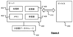
図6では、時計200は、任意の数の異なる構成によって実行されうる一般的な通信チャネル410を介してサーバ400と通信するものとして示されている。サーバ400およびデバイス200は、サーバ400と時計200との間に接続が確立されたときに通信することができる(留意点として、そのような接続は、移動デバイスを介したデータ接続、インターネットを介してのパーソナルコンピュータを介した直接接続などでありうる)。
In FIG. 6, watch 200 is shown as communicating with
サーバ400は、図示しない他の構成要素に加えて、メモリ406に動作可能に接続され、有線または無線接続を介して大容量データストレージデバイス402に動作可能更に接続された処理部404(プロセッサ)を含む。処理部404は、通信チャネル410を介してデバイス200に及びデバイス200から情報を送信および受信するように、送信器408および受信器409に動作可能に更に接続される。送受信される信号は、データ、通信、および/または他の伝搬信号を含みうる。送信器408および受信器409の機能は、信号送受信器に組み合わされてもよい。
The
通信チャネル410は、特定の通信技術に限定されるものではない。さらに、通信チャネル410は、単一の通信技術に限られるものではなく、即ち、チャネル410は、様々な技術を使用する幾つかの通信リンクを含んでもよい。例えば、通信チャネル410は、電気通信、光通信、および/または電磁通信などのための経路を提供するように適用されうる。そのようなものとして、通信チャネル410は、限定されるものではないが、電気回路、ワイヤおよび同軸ケーブルなどの導電体、光ファイバケーブル、コンバータ、無線周波数(RF)波、雰囲気、空間などのうちの1つ、または、これらの組み合わせを含む。さらに、通信チャネル410は、ルータ、中継器、バッファ、送信器、および受信器などの中間デバイスを含むことができる。
The
1つの例示的な構成では、通信チャネル410は、電話およびコンピュータネットワークを含む。さらに、通信チャネル410は、無線周波数、マイクロ波周波数、赤外線通信などの無線通信を適応させることができる。加えて、通信チャネル410は、衛星通信を適応させることができる。
In one exemplary configuration, the
サーバ400は、無線チャネルを介して時計200によってアクセス可能なリモートサーバであってもよい。サーバ400は、ローカルエリアネットワーク(LAN)、ワイドエリアネットワーク(WAN)、仮想プライベートネットワーク(VPN)などに設置されたネットワークサーバを含んでもよい。
サーバ400は、デスクトップまたはラップトップコンピュータなどのパーソナルコンピュータを含んでもよく、通信チャネル410は、パーソナルコンピュータと時計200との間に接続されたケーブルであってもよい。あるいは、パーソナルコンピュータは、サーバ400と時計200との間のインターネット接続を確立するように、時計200とサーバ400との間に接続されてもよい。あるいは、携帯電話または他の手持ち式デバイスは、インターネットを介してサーバ400に時計200を接続するために、インターネットへの無線接続を確立してもよい。
サーバ400は、大容量ストレージデバイス402に更に接続される(または、含む)。大容量ストレージデバイス402は、少なくともデジタル地図情報の記憶を含む。このデジタル地図情報は、デバイス200の着用者が移動したルートを決定し、該着用者が見ることができるように、GPS受信器204から得られたタイムスタンプ付き位置データや、加速度計206、フットパッドセンサ222などから得られた着用者の動きを示すデータなど、デバイスからのデータとともに使用されうる。
理解されるように、時計200は、ランニングまたは他の同様のタイプの運動を行っているときに、ランナまたは他のアスリートによって着用されるように設計されている。GPS受信器204および加速度計206などの時計200内の様々なセンサは、移動距離、現在速度など、このランニングに関するデータを取集し、このデータを、表示画面210を用いて着用者に表示する。
As will be appreciated, watch 200 is designed to be worn by a runner or other athlete when running or doing other similar types of exercise. Various sensors in the
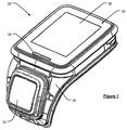
図1〜図4は、上述したように、リストストラップ(不図示)に取り外し可能に接続されうるフィットネス・モニタリング・モジュールの例を提供する。いくつかの実施形態では、モジュール28は、フィットネス・ウォッチ・モジュール、特に、例えばGPSなどのGNSS時計モジュールの形態をとることができる。他の実施形態では、モジュール28は、GNSS時計機能を含んでもよいし含まなくてもよい心拍数モニタモジュールの形態をとる。
1-4 provide examples of fitness monitoring modules that can be removably connected to a wrist strap (not shown) as described above. In some embodiments,
図1は、ハウジング30と、ハウジング30の上面に露出したディスプレイ36とを含む心拍数モニタモジュール28の斜視図を示す。入力デバイス32は、ディスプレイ36から離間されている。実質的に平坦なディスプレイ36は、ユーザに心拍数情報を表示するために入力デバイス32によって制御される。ディスプレイ36は、液晶ディスプレイ(LCD)を含みうる。LCDに加えて、ディスプレイは、照明34、例えばLCDの別の不透明なフレームを通って光るLEDを含む。
FIG. 1 shows a perspective view of a heart
照明34は、ユーザの心拍数に関する情報を伝達するために、時計モジュール28内の処理部(プロセッサ)によって制御される。一例では、照明34は、心拍数のおおよその周波数で点滅し、それによって、一見して心拍数の視覚化を提供する。加えて、または代わりに、別の例では、照明34の色は、特定の心拍数ゾーンを表す。照明34は、以下の配色に従って点滅しうる。

入力デバイス32は、ハウジング30から離れて延びる湾曲フランジ38によってメインハウジング30に接続される。湾曲フランジ38は、該モジュールがリストストラップ(不図示)に取り付けられたときにユーザの手首の周りを湾曲するように、ハウジング30から離れて延びる。入力デバイス32は、使用時にユーザの手首の側方に配置されるように設置される。入力デバイス32は、ユーザがモジュール28と情報のやり取りをするために、実質的に平坦な押圧面を有する。これにより、ユーザは、例えば心拍数モニタのメニューシステム内の所望の機能を選択するなど、押圧面に垂直な方向に押圧面を押圧し、モジュール28を制御することができる。この例では、入力デバイス32は、4方向ボタンの形態をとっている。
使用時にユーザの手首の側方に当たるように湾曲フランジ上に配置された入力デバイス32の位置は、多くの重要な利点を有する。例えば、これは、ユーザが、単一の指だけを用いてモジュール28と情報をやり取りすることを可能にする。より具体的には、ユーザは、時計28が巻かれたユーザの手首に向かって該表面を押すため、ユーザは、1本の指で入力デバイス32の押圧面を押すことができる。これは、ボタンが周縁の周りに配置され、ユーザが、指でボタンを押圧し且つ時計の他の縁に親指を使用して押圧力のバランスをとらなければならない従来の心拍数モニタまたは時計と対照的である。図1に示すように、例えば、実質的に平坦なディスプレイ36によって画定された平面は、入力デバイス32によって画定された平面に対してある角度で配置され、その2つの平面間の二面角は90度より小さく、典型的には20度と70度との間である。
The position of the
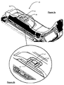
図2は、下側からの心拍数モジュール28の斜視図を示す。メインハウジング30から延びる湾曲フランジ38は、その遠位端に配置された電気コネクタ(不図示)を有しうる。これらの電気コネクタは、モジュール28内のバッテリを再充電するため、および/またはモジュール28からデータを抽出するため、またはモジュール28にデータを入力するために、モジュール28をドックに電気的に接続するために使用されうる。ハウジング30の下面は、光心拍数(OHR)センサにわたって拡がるドーム状部分60を含む。OHRセンサの検知部40は、ドーム状部分60内の開口を通って突出する。この例では、検知部40は、一対の発光ダイオード42a、42b(例えば、2つの緑色LED、または、緑色LEDと赤外LED)と、光検出器44とを含む。モジュール28が着用者の手首に装着されたときに、検知部40が、皮膚と接触して手首の前または後ろに当たる。ドーム状部分60は、モジュール28が装着されたときにモジュール28が動きにくくなるように圧力を加え、光検出器44への周囲光の侵入を防止または低減するように検知部40の突出部が皮膚内に押し込まれる。
FIG. 2 shows a perspective view of the
図3aおよび図3bは、検知部40がプリント回路基板50の上部のライザ48にどのように取り付けられるのかを詳細に示している。ライザ48の深さは、検知部40がドーム状部分60の表面を超えてどれだけ突出するのかを決定する。図4aおよび図4bの側面図は、検知部40が、距離dだけドーム状部分60の表面からどのように突出するのかを示している。距離dは、少なくとも0.1mmである。
3a and 3b show in detail how the
OHR検知部40は、脈拍および/または心拍数に関するデータ信号を処理することができるモジュール28内の処理部(プロセッサ)に動作可能に接続されうる。処理部は、典型的には、メモリとバッテリ等の電源とに接続される。バッテリは、例えば上記の電気コネクタの形態におけるI/Oポートを用いてモジュール28がドッキングされたときに再充電されうる。同じ電気コネクタは、処理部に/からデータを転送するためにも使用されうる。I/Oポートに加えて、モジュール28は、追加のデータを受信するために1以上の他のデバイスにモジュール28が無線で通信することを可能にするブルートゥース送受信器などの無線通信インタフェースを含んでもよい。例えば、身体に着用された(例えば、外部の心拍数モニタ)、または運動中に近くに装着された(例えば、サイクリング活動中にバイクに取り付けられた)他のデバイスは、追加のデータを送信するようにモジュール28と組み合わせてもよい。モジュールのユーザインタフェースは、ユーザが、そのような追加のデータをディスプレイ上で見ることを可能にしうる。いくつかの実施形態では、モジュール28は、フィットネス時計モジュール、特にGPSなどのGNSS時計モジュールの形態をとることができる。
The
モジュールのユーザインタフェースは、既に上述したディスプレイ36および入力デバイス32を含む。もちろん、他のユーザインタフェースの構成要素は、図面に示されているものの代わりに、または同様に提供されてもよい。図1〜図4に示されるようなモジュール28の更なる特徴は、WO2014/135709に記載されており、その内容は、参照により本明細書に組み込まれる。特に、そのようなモジュールがリストストラップに対して取り外し可能に装着されうるのかが記載されている。
The module user interface includes the
本発明の様々な態様および実施形態がこれまで説明されてきたが、本発明の範囲は、本明細書に記載された特定の構成に限定されるものではなく、代わりに、添付の特許請求の範囲内に収まるすべての構成、および、その変形および変更を包含するように拡張される。 Although various aspects and embodiments of the present invention have been described above, the scope of the present invention is not limited to the specific configurations described herein, but instead is It is expanded to encompass all configurations that fall within the scope, and variations and modifications thereof.
例えば、上述の詳細な説明に記載された好ましい実施形態は、ストラップを参照しない心拍数モニタモジュールに関するものであるが、モジュールをリストストラップに永久的に又は取り外し可能に取り付けることができることが理解されよう。更に、モジュールは、ディスプレイおよび/または入力デバイスを有するものとして説明したが、これらはオプションの構成要素である。適切なモジュールは、オプションのディスプレイ、オプションの入力デバイス、メモリ、無線受信器、および電気接点などの入出力デバイスのうちの1つ以上に接続されたバッテリおよび処理部を含みうる。 For example, while the preferred embodiments described in the detailed description above relate to a heart rate monitor module that does not reference a strap, it will be understood that the module can be permanently or removably attached to a wrist strap. . Further, although the module has been described as having a display and / or input device, these are optional components. Suitable modules may include batteries and processing units connected to one or more of input / output devices such as optional displays, optional input devices, memories, wireless receivers, and electrical contacts.
最後に、添付の特許請求の範囲は、本明細書に記載された特徴の特定の組み合わせを記載しているが、本発明の範囲は、特許請求の範囲に記載された特定の組み合わせに限定されるものではなく、現時点で添付の特許請求の範囲に特別に列挙された特定の組み合わせか否かに関係なく、代わりに、本明細書に開示された特徴または実施形態の任意の組み合わせを包含するように拡張されることに留意すべきである。 Finally, while the appended claims describe specific combinations of the features described herein, the scope of the present invention is limited to the specific combinations recited in the claims. It is not intended to encompass any combination of the features or embodiments disclosed herein, instead, whether or not it is a particular combination specifically recited in the appended claims at the present time. It should be noted that it is expanded as follows.
Claims (12)
ハウジングと、前記ハウジング内の光心拍数(OHR)センサとを含み、
前記OHRセンサは、ユーザの皮膚内に光を射出するように配置された少なくとも1つの発光体と、前記ユーザの前記皮膚を通って反射された光を検知するように配置された光検出器とを含む検知部を含み、
前記ハウジングはドーム状部分を含み、前記検知部は前記ドーム状部分の表面を通して露出され、前記検知部は前記ドーム状部分の前記表面の上に突出している、ことを特徴とする心拍数モニタ。 A heart rate monitor,
A housing and an optical heart rate (OHR) sensor in the housing;
The OHR sensor includes at least one light emitter disposed to emit light into the user's skin, and a photodetector disposed to detect light reflected through the user's skin. Including a detector including
The heart rate monitor according to claim 1, wherein the housing includes a dome-shaped portion, the detecting portion is exposed through a surface of the dome-shaped portion, and the detecting portion protrudes above the surface of the dome-shaped portion.
前記1以上の照明デバイスは、(i)心拍数情報に依存する周波数で点滅するように、および/または(ii)射出された光の色が所定の心拍数ゾーンに対応するように、制御される、ことを特徴とする請求項1乃至10のいずれか1項に記載の心拍数モニタ。 One or more lighting devices in addition to the display;
The one or more lighting devices may be controlled to (i) flash at a frequency that depends on heart rate information and / or (ii) the color of the emitted light corresponds to a predetermined heart rate zone. The heart rate monitor according to any one of claims 1 to 10, wherein
請求項1乃至11のいずれか1項に記載の心拍数モニタと、ユーザの腕または手首に前記時計を固定するためのストラップとを含む、ことを特徴とする時計。 A watch, optionally a fitness watch, comprising a heart rate monitor according to any one of claims 1 to 11 and a strap for securing the watch to a user's arm or wrist. To watch.
Applications Claiming Priority (3)
| Application Number | Priority Date | Filing Date | Title |
|---|---|---|---|
| GB1515657.3 | 2015-09-03 | ||
| GBGB1515657.3A GB201515657D0 (en) | 2015-09-03 | 2015-09-03 | Heart rate monitor |
| PCT/EP2016/070734 WO2017037242A1 (en) | 2015-09-03 | 2016-09-02 | Heart rate monitor |
Publications (2)
| Publication Number | Publication Date |
|---|---|
| JP2018529416A true JP2018529416A (en) | 2018-10-11 |
| JP2018529416A5 JP2018529416A5 (en) | 2019-09-26 |
Family
ID=54345745
Family Applications (1)
| Application Number | Title | Priority Date | Filing Date |
|---|---|---|---|
| JP2018511406A Pending JP2018529416A (en) | 2015-09-03 | 2016-09-02 | Heart rate monitor |
Country Status (7)
| Country | Link |
|---|---|
| US (1) | US20180256049A1 (en) |
| EP (1) | EP3344131A1 (en) |
| JP (1) | JP2018529416A (en) |
| KR (1) | KR20180049022A (en) |
| CN (1) | CN108024744A (en) |
| GB (1) | GB201515657D0 (en) |
| WO (1) | WO2017037242A1 (en) |
Families Citing this family (28)
| Publication number | Priority date | Publication date | Assignee | Title |
|---|---|---|---|---|
| US20160019360A1 (en) | 2013-12-04 | 2016-01-21 | Apple Inc. | Wellness aggregator |
| CN111128339B (en) | 2014-09-02 | 2024-02-09 | 苹果公司 | Physical activity and fitness monitor |
| EP3337583B1 (en) | 2015-08-20 | 2024-01-17 | Apple Inc. | Exercise-based watch face |
| AU2017100667A4 (en) | 2016-06-11 | 2017-07-06 | Apple Inc. | Activity and workout updates |
| US11216119B2 (en) | 2016-06-12 | 2022-01-04 | Apple Inc. | Displaying a predetermined view of an application |
| US10736543B2 (en) | 2016-09-22 | 2020-08-11 | Apple Inc. | Workout monitor interface |
| US10845955B2 (en) | 2017-05-15 | 2020-11-24 | Apple Inc. | Displaying a scrollable list of affordances associated with physical activities |
| DK180241B1 (en) | 2018-03-12 | 2020-09-08 | Apple Inc | User interfaces for health monitoring |
| DK201870378A1 (en) | 2018-05-07 | 2020-01-13 | Apple Inc. | Displaying user interfaces associated with physical activities |
| US11317833B2 (en) | 2018-05-07 | 2022-05-03 | Apple Inc. | Displaying user interfaces associated with physical activities |
| CN109009055A (en) * | 2018-08-08 | 2018-12-18 | 加动健康科技(芜湖)有限公司 | Heart rate measurement unit |
| US10953307B2 (en) | 2018-09-28 | 2021-03-23 | Apple Inc. | Swim tracking and notifications for wearable devices |
| DK201970532A1 (en) | 2019-05-06 | 2021-05-03 | Apple Inc | Activity trends and workouts |
| US11228835B2 (en) | 2019-06-01 | 2022-01-18 | Apple Inc. | User interfaces for managing audio exposure |
| US11152100B2 (en) | 2019-06-01 | 2021-10-19 | Apple Inc. | Health application user interfaces |
| US11209957B2 (en) | 2019-06-01 | 2021-12-28 | Apple Inc. | User interfaces for cycle tracking |
| US11979467B2 (en) | 2019-06-01 | 2024-05-07 | Apple Inc. | Multi-modal activity tracking user interface |
| DK201970534A1 (en) | 2019-06-01 | 2021-02-16 | Apple Inc | User interfaces for monitoring noise exposure levels |
| US11234077B2 (en) | 2019-06-01 | 2022-01-25 | Apple Inc. | User interfaces for managing audio exposure |
| CN114286975A (en) | 2019-09-09 | 2022-04-05 | 苹果公司 | Research user interface |
| DK202070613A1 (en) | 2020-02-14 | 2021-10-15 | Apple Inc | User interfaces for workout content |
| DK181037B1 (en) | 2020-06-02 | 2022-10-10 | Apple Inc | User interfaces for health applications |
| US11698710B2 (en) | 2020-08-31 | 2023-07-11 | Apple Inc. | User interfaces for logging user activities |
| EP4323992A1 (en) | 2021-05-15 | 2024-02-21 | Apple Inc. | User interfaces for group workouts |
| US11915805B2 (en) | 2021-06-06 | 2024-02-27 | Apple Inc. | User interfaces for shared health-related data |
| US20230070665A1 (en) * | 2021-09-09 | 2023-03-09 | GenoEmote LLC | Method and system for validation of disease condition reprogramming based on personality to disease condition mapping |
| US11977729B2 (en) | 2022-06-05 | 2024-05-07 | Apple Inc. | Physical activity information user interfaces |
| US20230390626A1 (en) | 2022-06-05 | 2023-12-07 | Apple Inc. | User interfaces for physical activity information |
Citations (7)
| Publication number | Priority date | Publication date | Assignee | Title |
|---|---|---|---|---|
| JP2004237066A (en) * | 2002-12-11 | 2004-08-26 | Masatoshi Shibuya | Ear hanging type pulsimeter |
| JP2014166215A (en) * | 2013-02-28 | 2014-09-11 | Rohm Co Ltd | Pulse wave sensor |
| JP2014180291A (en) * | 2013-03-18 | 2014-09-29 | Seiko Epson Corp | Biological information detector |
| US20140361147A1 (en) * | 2014-04-07 | 2014-12-11 | Physical Enterprises, Inc. | Systems and Methods for Monitoring Physiological Parameters |
| WO2015049963A1 (en) * | 2013-10-03 | 2015-04-09 | コニカミノルタ株式会社 | Bio-information measurement device and method therefor |
| JP2015119911A (en) * | 2013-12-25 | 2015-07-02 | セイコーエプソン株式会社 | Biological body information detector |
| JP2015142713A (en) * | 2013-12-25 | 2015-08-06 | セイコーエプソン株式会社 | Biological body information measurement unit |
Family Cites Families (8)
| Publication number | Priority date | Publication date | Assignee | Title |
|---|---|---|---|---|
| JP3722203B2 (en) * | 2000-06-14 | 2005-11-30 | 株式会社デンソー | Pulse wave sensor |
| JP4485234B2 (en) * | 2004-03-26 | 2010-06-16 | セイコーインスツル株式会社 | Biological information measuring device |
| US20140213917A1 (en) * | 2011-06-23 | 2014-07-31 | Butterfleye SAL | Waterproof heart rate measuring apparatus |
| US20130267854A1 (en) * | 2012-04-09 | 2013-10-10 | Jami Johnson | Optical Monitoring and Computing Devices and Methods of Use |
| GB201304220D0 (en) * | 2013-03-08 | 2013-04-24 | Tomtom Int Bv | Fitness watch case |
| CN104055508A (en) * | 2013-03-18 | 2014-09-24 | 精工爱普生株式会社 | Biological Information Detection Apparatus |
| US20160242659A1 (en) * | 2015-02-20 | 2016-08-25 | Seiko Epson Corporation | Pulse-wave measuring module, biological-information measuring module, and electronic device |
| JP2016195661A (en) * | 2015-04-03 | 2016-11-24 | セイコーエプソン株式会社 | Exercise effect determination method and exercise effect determination system |
-
2015
- 2015-09-03 GB GBGB1515657.3A patent/GB201515657D0/en not_active Ceased
-
2016
- 2016-09-02 JP JP2018511406A patent/JP2018529416A/en active Pending
- 2016-09-02 CN CN201680054004.5A patent/CN108024744A/en active Pending
- 2016-09-02 US US15/756,970 patent/US20180256049A1/en not_active Abandoned
- 2016-09-02 EP EP16760477.6A patent/EP3344131A1/en not_active Withdrawn
- 2016-09-02 WO PCT/EP2016/070734 patent/WO2017037242A1/en active Application Filing
- 2016-09-02 KR KR1020187009496A patent/KR20180049022A/en unknown
Patent Citations (7)
| Publication number | Priority date | Publication date | Assignee | Title |
|---|---|---|---|---|
| JP2004237066A (en) * | 2002-12-11 | 2004-08-26 | Masatoshi Shibuya | Ear hanging type pulsimeter |
| JP2014166215A (en) * | 2013-02-28 | 2014-09-11 | Rohm Co Ltd | Pulse wave sensor |
| JP2014180291A (en) * | 2013-03-18 | 2014-09-29 | Seiko Epson Corp | Biological information detector |
| WO2015049963A1 (en) * | 2013-10-03 | 2015-04-09 | コニカミノルタ株式会社 | Bio-information measurement device and method therefor |
| JP2015119911A (en) * | 2013-12-25 | 2015-07-02 | セイコーエプソン株式会社 | Biological body information detector |
| JP2015142713A (en) * | 2013-12-25 | 2015-08-06 | セイコーエプソン株式会社 | Biological body information measurement unit |
| US20140361147A1 (en) * | 2014-04-07 | 2014-12-11 | Physical Enterprises, Inc. | Systems and Methods for Monitoring Physiological Parameters |
Also Published As
| Publication number | Publication date |
|---|---|
| KR20180049022A (en) | 2018-05-10 |
| GB201515657D0 (en) | 2015-10-21 |
| EP3344131A1 (en) | 2018-07-11 |
| US20180256049A1 (en) | 2018-09-13 |
| CN108024744A (en) | 2018-05-11 |
| WO2017037242A1 (en) | 2017-03-09 |
Similar Documents
| Publication | Publication Date | Title |
|---|---|---|
| JP2018529416A (en) | Heart rate monitor | |
| EP3344121B1 (en) | Display arrangement for watch case | |
| US9501044B2 (en) | Fitness watch case | |
| EP2926726B1 (en) | Heart rate monitor and strap | |
| US10321293B2 (en) | Methods for communicating sensor data between devices | |
| JP6486439B2 (en) | Motion capture system, method and program | |
| KR102210628B1 (en) | Fitness monitor | |
| US11064910B2 (en) | Physical activity monitoring system | |
| US20180246474A1 (en) | User Interface Arrangement for Watch Case | |
| JP7256563B2 (en) | Coupling mechanism and coupling method for information processing terminal device | |
| US20240149149A1 (en) | Mobile Handheld Gaming Controller | |
| KR20170121642A (en) | Smart shoes type mobile terminal and operating method thereof |
Legal Events
| Date | Code | Title | Description |
|---|---|---|---|
| A521 | Request for written amendment filed |
Free format text: JAPANESE INTERMEDIATE CODE: A523 Effective date: 20190813 |
|
| A621 | Written request for application examination |
Free format text: JAPANESE INTERMEDIATE CODE: A621 Effective date: 20190813 |
|
| A977 | Report on retrieval |
Free format text: JAPANESE INTERMEDIATE CODE: A971007 Effective date: 20200708 |
|
| A131 | Notification of reasons for refusal |
Free format text: JAPANESE INTERMEDIATE CODE: A131 Effective date: 20200710 |
|
| A02 | Decision of refusal |
Free format text: JAPANESE INTERMEDIATE CODE: A02 Effective date: 20210222 |