JP2018525045A - Flexible planned kit knee protocol - Google Patents
Flexible planned kit knee protocol Download PDFInfo
- Publication number
- JP2018525045A JP2018525045A JP2017561840A JP2017561840A JP2018525045A JP 2018525045 A JP2018525045 A JP 2018525045A JP 2017561840 A JP2017561840 A JP 2017561840A JP 2017561840 A JP2017561840 A JP 2017561840A JP 2018525045 A JP2018525045 A JP 2018525045A
- Authority
- JP
- Japan
- Prior art keywords
- femur
- block
- patient
- resection
- plan
- Prior art date
- Legal status (The legal status is an assumption and is not a legal conclusion. Google has not performed a legal analysis and makes no representation as to the accuracy of the status listed.)
- Pending
Links
Images


Classifications
-
- A—HUMAN NECESSITIES
- A61—MEDICAL OR VETERINARY SCIENCE; HYGIENE
- A61B—DIAGNOSIS; SURGERY; IDENTIFICATION
- A61B17/00—Surgical instruments, devices or methods, e.g. tourniquets
- A61B17/16—Bone cutting, breaking or removal means other than saws, e.g. Osteoclasts; Drills or chisels for bones; Trepans
- A61B17/17—Guides or aligning means for drills, mills, pins or wires
- A61B17/1739—Guides or aligning means for drills, mills, pins or wires specially adapted for particular parts of the body
- A61B17/1764—Guides or aligning means for drills, mills, pins or wires specially adapted for particular parts of the body for the knee
-
- A—HUMAN NECESSITIES
- A61—MEDICAL OR VETERINARY SCIENCE; HYGIENE
- A61B—DIAGNOSIS; SURGERY; IDENTIFICATION
- A61B17/00—Surgical instruments, devices or methods, e.g. tourniquets
- A61B17/14—Surgical saws ; Accessories therefor
- A61B17/15—Guides therefor
- A61B17/154—Guides therefor for preparing bone for knee prosthesis
- A61B17/155—Cutting femur
-
- A—HUMAN NECESSITIES
- A61—MEDICAL OR VETERINARY SCIENCE; HYGIENE
- A61B—DIAGNOSIS; SURGERY; IDENTIFICATION
- A61B17/00—Surgical instruments, devices or methods, e.g. tourniquets
- A61B17/14—Surgical saws ; Accessories therefor
- A61B17/15—Guides therefor
- A61B17/154—Guides therefor for preparing bone for knee prosthesis
- A61B17/157—Cutting tibia
-
- A—HUMAN NECESSITIES
- A61—MEDICAL OR VETERINARY SCIENCE; HYGIENE
- A61B—DIAGNOSIS; SURGERY; IDENTIFICATION
- A61B34/00—Computer-aided surgery; Manipulators or robots specially adapted for use in surgery
- A61B34/10—Computer-aided planning, simulation or modelling of surgical operations
-
- A—HUMAN NECESSITIES
- A61—MEDICAL OR VETERINARY SCIENCE; HYGIENE
- A61B—DIAGNOSIS; SURGERY; IDENTIFICATION
- A61B34/00—Computer-aided surgery; Manipulators or robots specially adapted for use in surgery
- A61B34/20—Surgical navigation systems; Devices for tracking or guiding surgical instruments, e.g. for frameless stereotaxis
-
- A—HUMAN NECESSITIES
- A61—MEDICAL OR VETERINARY SCIENCE; HYGIENE
- A61B—DIAGNOSIS; SURGERY; IDENTIFICATION
- A61B90/00—Instruments, implements or accessories specially adapted for surgery or diagnosis and not covered by any of the groups A61B1/00 - A61B50/00, e.g. for luxation treatment or for protecting wound edges
- A61B90/06—Measuring instruments not otherwise provided for
-
- A—HUMAN NECESSITIES
- A61—MEDICAL OR VETERINARY SCIENCE; HYGIENE
- A61B—DIAGNOSIS; SURGERY; IDENTIFICATION
- A61B17/00—Surgical instruments, devices or methods, e.g. tourniquets
- A61B17/02—Surgical instruments, devices or methods, e.g. tourniquets for holding wounds open; Tractors
- A61B17/025—Joint distractors
- A61B2017/0268—Joint distractors for the knee
-
- A—HUMAN NECESSITIES
- A61—MEDICAL OR VETERINARY SCIENCE; HYGIENE
- A61B—DIAGNOSIS; SURGERY; IDENTIFICATION
- A61B34/00—Computer-aided surgery; Manipulators or robots specially adapted for use in surgery
- A61B34/10—Computer-aided planning, simulation or modelling of surgical operations
- A61B2034/101—Computer-aided simulation of surgical operations
- A61B2034/105—Modelling of the patient, e.g. for ligaments or bones
-
- A—HUMAN NECESSITIES
- A61—MEDICAL OR VETERINARY SCIENCE; HYGIENE
- A61B—DIAGNOSIS; SURGERY; IDENTIFICATION
- A61B34/00—Computer-aided surgery; Manipulators or robots specially adapted for use in surgery
- A61B34/10—Computer-aided planning, simulation or modelling of surgical operations
- A61B2034/108—Computer aided selection or customisation of medical implants or cutting guides
-
- A—HUMAN NECESSITIES
- A61—MEDICAL OR VETERINARY SCIENCE; HYGIENE
- A61B—DIAGNOSIS; SURGERY; IDENTIFICATION
- A61B34/00—Computer-aided surgery; Manipulators or robots specially adapted for use in surgery
- A61B34/20—Surgical navigation systems; Devices for tracking or guiding surgical instruments, e.g. for frameless stereotaxis
- A61B2034/2046—Tracking techniques
- A61B2034/2048—Tracking techniques using an accelerometer or inertia sensor
-
- A—HUMAN NECESSITIES
- A61—MEDICAL OR VETERINARY SCIENCE; HYGIENE
- A61B—DIAGNOSIS; SURGERY; IDENTIFICATION
- A61B90/00—Instruments, implements or accessories specially adapted for surgery or diagnosis and not covered by any of the groups A61B1/00 - A61B50/00, e.g. for luxation treatment or for protecting wound edges
- A61B90/06—Measuring instruments not otherwise provided for
- A61B2090/061—Measuring instruments not otherwise provided for for measuring dimensions, e.g. length
-
- A—HUMAN NECESSITIES
- A61—MEDICAL OR VETERINARY SCIENCE; HYGIENE
- A61B—DIAGNOSIS; SURGERY; IDENTIFICATION
- A61B90/00—Instruments, implements or accessories specially adapted for surgery or diagnosis and not covered by any of the groups A61B1/00 - A61B50/00, e.g. for luxation treatment or for protecting wound edges
- A61B90/06—Measuring instruments not otherwise provided for
- A61B2090/064—Measuring instruments not otherwise provided for for measuring force, pressure or mechanical tension
-
- A—HUMAN NECESSITIES
- A61—MEDICAL OR VETERINARY SCIENCE; HYGIENE
- A61B—DIAGNOSIS; SURGERY; IDENTIFICATION
- A61B90/00—Instruments, implements or accessories specially adapted for surgery or diagnosis and not covered by any of the groups A61B1/00 - A61B50/00, e.g. for luxation treatment or for protecting wound edges
- A61B90/39—Markers, e.g. radio-opaque or breast lesions markers
- A61B2090/3966—Radiopaque markers visible in an X-ray image
-
- A—HUMAN NECESSITIES
- A61—MEDICAL OR VETERINARY SCIENCE; HYGIENE
- A61B—DIAGNOSIS; SURGERY; IDENTIFICATION
- A61B34/00—Computer-aided surgery; Manipulators or robots specially adapted for use in surgery
- A61B34/25—User interfaces for surgical systems
Landscapes
- Health & Medical Sciences (AREA)
- Surgery (AREA)
- Life Sciences & Earth Sciences (AREA)
- Engineering & Computer Science (AREA)
- Molecular Biology (AREA)
- Public Health (AREA)
- Veterinary Medicine (AREA)
- Biomedical Technology (AREA)
- Heart & Thoracic Surgery (AREA)
- Medical Informatics (AREA)
- Nuclear Medicine, Radiotherapy & Molecular Imaging (AREA)
- Animal Behavior & Ethology (AREA)
- General Health & Medical Sciences (AREA)
- Oral & Maxillofacial Surgery (AREA)
- Dentistry (AREA)
- Orthopedic Medicine & Surgery (AREA)
- Robotics (AREA)
- Pathology (AREA)
- Physical Education & Sports Medicine (AREA)
- Transplantation (AREA)
- Surgical Instruments (AREA)
- Prostheses (AREA)
Abstract
全膝関節置換処置を計画し準備する方法であって、患者の脛骨及び大腿骨の三次元モデルを作製し、脛骨及び大腿骨のサイズを三次元モデルに基づいた範囲内になるように設定し、三次元モデルに基づいて脛骨及び大腿骨の各々についての切除道具を選択し、そして切除道具をパッケージすることを含む方法。外科手術処置を計画し準備する方法は、1つ以上の骨の三次元モデルを作製し、三次元モデルに基づいて1つ以上の骨のサイズを設定し、三次元骨モデルに基づいて外科手術計画を記録し、外科手術計画に基づいて1つ以上の骨のための第一手術道具を選択し、そして第一手術道具の性能パラメータに基づいて第二手術道具の選択を評価することを含み得る。【選択図】図3A method for planning and preparing a total knee replacement procedure by creating a 3D model of the patient's tibia and femur and setting the size of the tibia and femur to be within a range based on the 3D model. Selecting a cutting tool for each of the tibia and femur based on the three-dimensional model and packaging the cutting tool. A method for planning and preparing a surgical procedure creates a three-dimensional model of one or more bones, sets the size of one or more bones based on the three-dimensional model, and performs a surgical operation based on the three-dimensional bone model. Recording the plan, selecting a first surgical tool for one or more bones based on the surgical plan, and evaluating the selection of the second surgical tool based on the performance parameters of the first surgical tool. obtain. [Selection] Figure 3
Description
本願は、その全体を参照により本明細書に援用される、2015年5月28日に出願された、発明の名称「FLEXIBLY PLANNED KITTED KNEE PROTOCOL」である、Brown氏らの米国特許仮出願第62/167591号明細書の優先権の利益を主張する。 This application is a US Patent Provisional Application No. 62 to Brown et al., Filed May 28, 2015, which is incorporated herein by reference in its entirety, with the title “FLEXIBLY PLANED KITTED KNEPRO PROTOCOL”. Claims the benefit of the priority of / 167591.
本願は、概して、関節形成処置を計画し実施するためのシステム及び方法に関するが、決してこれに限定されるものではない。さらに詳細には、本開示は、手術前及び手術中の情報に基づいた外科手術装置及びシステムの選択及び使用のための手術前計画技術に関するが、決してこれらに限定されるものではない。 The present application relates generally to, but is in no way limited to, systems and methods for planning and performing arthroplasty procedures. More specifically, the present disclosure relates to, but is in no way limited to, pre-operative planning techniques for selection and use of surgical devices and systems based on pre- and intra-operative information.
完全関節置換技術のための関節形成処置は、多くの異なる成分、例えば計画システム、器具、技術、処置及びその他の使用を含み得る。場合によっては、同一又は類似の結果を達成するために使用できる複数の器具又は技術がある。外科医には、選好及び特定の患者に基づいて任意の特定の外科手術においてどの器具及び技術を使用するかを選択する余地がある。しかしながら、これら異なる構成成分の各々は必ずしも互いの適合性に役立つわけではない。このため、多くの場合、外科医は多数の決断をしなければならず、その各々は所望の処置の各段階でどのような結果が得られるかについての推定又は仮定に基づく可能性がある。これらの決断は、事前計画プロセス及び外科手術の長さ及び費用を増加させる可能性があり、また計画プロセスにエラーを導入するもとともなり得る。 Arthroplasty procedures for complete joint replacement techniques can include many different components, such as planning systems, instruments, techniques, procedures, and other uses. In some cases, there are multiple instruments or techniques that can be used to achieve the same or similar results. The surgeon has room to select which instruments and techniques to use in any particular surgical procedure based on preferences and specific patients. However, each of these different components does not necessarily help compatibility with each other. Thus, in many cases, the surgeon must make a number of decisions, each of which may be based on an estimate or assumption about what results will be obtained at each stage of the desired procedure. These decisions can increase the length and cost of the pre-planning process and surgery, and can also introduce errors into the planning process.
手術器具の例は、ある特許文献に記載されている(例えば、特許文献1〜3参照。)。 Examples of surgical instruments are described in a certain patent document (for example, see Patent Documents 1 to 3).
中でも、解決すべき課題には、外科医が、選択された器具及び技術の各々がその後の決断にどのように影響を及ぼすかについて知ることなく、実施しなければならない一連の器具及び技術を選択することによって外科手術を手作業で計画しなければならないという必要性が含まれ得ることを本発明者らは認識している。 Among other issues, the problem to be solved is that the surgeon selects a set of instruments and techniques that must be implemented without knowing how each of the selected instruments and techniques affects subsequent decisions. We recognize that this may involve the need to manually plan the surgery.
本発明者らは、外科医に出発点のリストを提供し、そして事前の入力に基づいた複数の最適なその後のステップにより外科医に指示することによって事前計画及び手術中の計画手順を簡略化できることがわかった。 We can provide the surgeon with a list of starting points and simplify the pre-planning and intra-operative planning procedures by instructing the surgeon with multiple optimal subsequent steps based on prior input. all right.
本発明の主題は、例えば、異なる結果、同一の結果又は同等の結果を達成し得る異なる手術道具及び外科手術技術のメニューを含む検索可能なデータベースを外科医に提供することによって、課題に対する解決策の提供を支援することができる。したがって、データベースは、互いに適合性である手術道具、互いに半適合性である手術道具及び互いに適合性でない手術道具のマトリックスを含み得る。そのため、望ましいオプションとして、患者の特徴又は外科医の選好に基づくなど、選択された外科手術又は技術の機能又はステップを外科手術計画に入力し、コンピュータデータベースは、完全な外科手術計画が開発され得るまでの所望のオプション、特徴又はステップと適合性である他の手術道具及び技術を提示できる。 The subject of the present invention is a solution to the problem, for example, by providing a surgeon with a searchable database that includes a menu of different surgical tools and surgical techniques that can achieve different results, the same result, or equivalent results. Can help provide. Thus, the database may include a matrix of surgical tools that are compatible with each other, surgical tools that are semi-compatible with each other, and a matrix of surgical tools that are not compatible with each other. Thus, as a preferred option, the selected surgical or technique functions or steps, such as based on patient characteristics or surgeon preferences, are entered into the surgical plan, and the computer database can be developed until a complete surgical plan can be developed. Other surgical tools and techniques can be presented that are compatible with the desired options, features or steps.
全膝関節置換処置を計画し準備する方法は、患者の脛骨及び大腿骨の三次元モデルを作製し、脛骨及び大腿骨のサイズを三次元モデルに基づいた範囲内に設定し、三次元モデルに基づいて脛骨及び大腿骨の各々について切除道具を選択し、そして切除道具をパッケージすることを含み得る。 The method of planning and preparing a total knee replacement procedure involves creating a 3D model of the patient's tibia and femur, setting the size of the tibia and femur within a range based on the 3D model, and creating a 3D model. Selecting a resection tool for each of the tibia and femur based on and packaging the resection tool.
外科手術を計画し準備する方法は、1つ以上の骨の三次元骨モデルを作製し、三次元モデルに基づいて1つ以上の骨のサイズを設定し、三次元骨モデルに基づいて外科手術計画を記録し、外科手術計画に基づいて1つ以上の骨について第一手術道具を選択し、そして第一手術道具の性能パラメータに基づいて第二の手術道具の選択を評価することを含み得る。 A method for planning and preparing a surgical procedure is to create a three-dimensional bone model of one or more bones, set one or more bone sizes based on the three-dimensional model, and perform a surgical operation based on the three-dimensional bone model. Recording the plan, selecting a first surgical tool for one or more bones based on the surgical plan, and evaluating the selection of the second surgical tool based on the performance parameters of the first surgical tool. .
この概要は、本願の主題の概要を提供することを意図するものである。本発明の排他的又は包括的説明を提供することを意図するものではない。詳細な説明は本願についてのさらなる情報を提供するために含められる。 This summary is intended to provide an overview of the subject matter of the present application. It is not intended to provide an exclusive or comprehensive description of the invention. A detailed description is included to provide further information about the present application.
必ずしも縮尺通りに描画されているとは限らない図面中、同様の数字は異なる図で類似した構成要素を説明する場合がある。異なる下付き文字を有する同様の数字は、類似の構成要素の異なる例を表し得る。図面は、概して例示のために本明細書で検討する様々な実施形態を説明するものであって、決して限定するものではない。 In the drawings, which are not necessarily drawn to scale, like numerals may describe similar components in different views. Similar numbers with different subscripts may represent different examples of similar components. The drawings generally illustrate various embodiments discussed herein for purposes of illustration and are in no way limiting.
図1は処置の計画を決定し提供する方法を説明するフローチャートである。概して、本明細書中で提供する外科手術計画は、入力された患者データ(患者様(擬人化データ)、MRI、CT又はX線)に基づいて、三次元(3D)モデル又は他の情報を作成することができる。これによって、特定の患者についての処置を実施するために必要な構成要素の(一般的又は正確な)サイズ設定を可能にすることができる。外科手術では、遠位大腿骨切除を実施し位置決定することができ、そしてモデルの作成で外科医が学習したものに基づいて様々な異なる器具を用いて実施することができる。図7〜17で示される調節可能な輪郭ブロックを遠位大腿骨切除後に使用してインプラントのサイズ設定をすることができる。調節可能な輪郭ブロックのサイズ範囲は、3Dモデル又は患者様データに基づいた計画から決定することができ、その一方で、遠位大腿骨切除の実際の位置及びサイズは、外科手術で実施することができる。外科手術では、遠位大腿骨切除を実施し位置決定し、そしてモデルの作製及び遠位大腿骨切除の実施で外科医が学習したことに基づいて様々な異なる器具を使用して実施することができる。脛骨サイズ及び範囲は計画によって決定することができる。 FIG. 1 is a flowchart illustrating a method for determining and providing a treatment plan. In general, the surgical plans provided herein are based on input patient data (patient-like (personification data), MRI, CT, or X-rays) to generate a three-dimensional (3D) model or other information. Can be created. This may allow for (general or accurate) sizing of the components necessary to perform the procedure for a particular patient. In surgery, a distal femoral resection can be performed and located, and can be performed using a variety of different instruments based on what the surgeon has learned in creating the model. The adjustable contour block shown in FIGS. 7-17 can be used after distal femoral resection to size the implant. The adjustable contour block size range can be determined from a 3D model or a plan based on patient-like data, while the actual location and size of the distal femoral resection should be performed surgically Can do. In surgery, a distal femoral resection can be performed and positioned, and performed using a variety of different instruments based on what the surgeon has learned in creating the model and performing the distal femoral resection. . The tibial size and extent can be determined by planning.
図1を参照すると、フローチャート200は処置を計画するためのプロセスを示す。計画された処置は生体構造の任意の適切又は選択された部分についてであり得ることがわかる。例えば、股関節全置換術(THA)を対象に対して実施することができる。THAは近位大腿骨部分及び寛骨臼の切除と、それに続いて近位大腿骨及び寛骨臼のプロテーゼ部材の移植を含み得る。さらに、膝関節全置換、部分膝関節置換、肩関節置換及び肘関節置換もまた、患者に移植されるプロテーゼシステムのさらなる例であり得る。完全関節形成術(概して関節接合面の2つの対向する部分を置換して、自然の関節を完全に置換することを含むと理解される)及び部分処置(2つの骨セクション間の関節接合部分の全体未満を置換する)を実施することができると理解される。様々な実施形態において、部分膝関節形成は、単独又は脛骨の内側部もしくは外側部の各々と組み合わせた、大腿骨の内側顆もしくは外側顆の切除又は置換を含み得る。部分股関節形成は、股関節の一部分だけの切除又は置換、例えば大腿骨頭の切除もしくは置換及び/又は寛骨臼もしくは生体構造のこれらの部分の選択された部分だけの切除もしくは置換を含み得ることも理解される。同様に、例えば非ヒト又は生きている対象の任意の選択された部分の完全又は全置換を、計画及び/又は実施することができる。以下の考察は概して膝関節形成に関し、これは完全膝関節形成を含み得る。完全膝関節形成では、遠位大腿骨及び近位脛骨を切除してプロテーゼ構成要素と置換することができる。プロテーゼ構成要素は関節で相互作用して、最適又は選択された解剖学的相互作用を反映及び/又は模倣することができる。これは股関節での骨盤との相互作用も含み得る。
Referring to FIG. 1, a
最初に、フローチャート200に示したプロセスは、開始ブロック222から始めることができる。フローチャート200に示す方法は、プロセッサシステムによって実行される命令に組み入れることができると理解される。プロセッサシステムは、ハードディスクドライブ、ネットワークメモリアクセス、又は他のメモリシステムなどの媒体に記憶させることができる命令を実行する汎用プロセッサを含み得る。さらに、プロセッサは、特定用途向け集積回路(ASIC)などの特定のプロセッサであり得る。しかしながら、様々な実施形態によると、フローチャート200で示される方法は、外科医などのユーザからの入力によるか、又はシステム内の命令に基づいて決定された計画を達成するための出力を提供するのを支援することができる。出力には、明細書中でさらに検討するように、器具部分、プロテーゼシステムの構成要素のリスト、及び/あるいは器具もしくはプロテーゼ部分を操作するか又は処置に組み入れて計画した結果を達成するための命令が含まれ得る。命令は、ガイド又はサイザーなどの選択された器具用の設定を含み得る。様々な例において、命令は、手持ち式又は携帯用電子機器で動作するように構成されたBiometOSソフトウェアに含めることができる。
Initially, the process shown in
ブロック222で方法を開始した後、対象データをブロック224で受信することができる。対象データは、三次元画像データもしくは二次元画像データ、又はそれらの組み合わせなどの任意の適切な対象データであり得る。例えば、対象の三次元画像を作成するために使用される磁気共鳴画像(MRI)を組み入れるか又はアクセスすることができる。さらに、又はMRIデータに加えて、コンピュータ断層撮影法(CT)画像データ及びX線を取得することができる。CT画像データは、計画を選択する際に解析又は使用される三次元画像データでもあり得る。二次元画像データを使用して、例えば2つの実質的に直交する画像を用いることによって計画を作成するのを支援して、対象の一部の三次元モデルを復元することもできる。様々な実施形態によると、二次元画像データを使用して、二次元画像データに基づいて三次元復元物を作成することができる。3D復元物は、ベルギーの企業であるMaterialise N.V.によって販売されているMIMICS(登録商標)コンピュータソフトウェア又はFEIによって販売されているAmira(商標)コンピュータソフトウェアなどの様々なソフトウェアプログラムを利用して作製することができる。ソフトウェアプログラムは、選択されたプロセッシング又はプロセッサシステムによって実行されるアルゴリズムの命令である。図4Aは、モデル化遠位大腿骨402及びモデル化近位脛骨400として図4Bの大腿骨F及び脛骨Tの例示的3D復元物を示す。
After starting the method at
さらに、二次元復元物も作製することができる。三次元復元物は対象から取得した実際の画像データに基づいて形成された対象のモデルであり得る。したがって、モデルは、例えばディスプレーデバイスを用いた表示用に作成された画像、例えばコンピュータで作成された画像であり得る。二次元画像データは、選択されたイメージングシステム、例えば蛍光透視法システム、Cアームイメージングシステム、及び同種のもので獲得される二次元X線を含み得る。 Furthermore, a two-dimensional reconstruction can also be produced. The three-dimensional reconstruction can be a model of the object formed based on actual image data acquired from the object. Thus, the model can be, for example, an image created for display using a display device, such as an image created on a computer. The two-dimensional image data may include two-dimensional X-rays acquired with selected imaging systems, such as fluoroscopy systems, C-arm imaging systems, and the like.
解剖学的又は物理学的測定、事前処置、及び同種のものを含む、対象に関するさらなるデータを取得することができる。さらなる患者データは、処置の計画、例えば過去の損傷及び/又は疾患の矯正を支援することができる。したがって、対象から取得されたデータは画像データに限定される必要はないと理解される。さらなる患者データを使用して、構成要素をチェックするか又はさらには選択することもでき、例えば患者のサイズを決定することができる。さらなる患者データは人類学的データを含み得る。身体計測データは多くのソースから公的に入手可能であり、中でも、身体セグメントの長さ、密度、質量及び慣性特性、ならびに質量の中心及び回転軸線を含み得る。例えば、David Winter, Biomechanics and Motor Control of Human Movement, 4th Edition, Chapter 4, Anthropometry, 2009, John Wiley & Sons, Inc.を参照のこと。Winterの本の図4.1は、例えば身長の割合として表される様々な身体セグメント長さを提供する。国防総省は身体測定リソースのコレクションを管理している。例えば“The Body Size of Soldiers:U.S. Army Anthropometry − 1966”by Robert M. White and Edmund Churchill, December 1971 at http://www.dtic.mil/get−tr−doc/pdf?AD=AD0743465を参照。例では、身体計測データを単独で使用して、例えばサイズの範囲の決定、器具の決定、軟組織を再検討する方法を考慮する等によって外科手術計画又は外科手術計画の一部を行うことができる。
Additional data about the subject can be obtained, including anatomical or physical measurements, pretreatment, and the like. Additional patient data can assist in the planning of treatment, eg, correction of past damage and / or disease. Therefore, it is understood that the data acquired from the object need not be limited to image data. Additional patient data can be used to check or even select components, for example to determine patient size. Additional patient data may include anthropological data. Anthropometric data is publicly available from a number of sources and may include, among other things, the length, density, mass and inertial properties of the body segment, as well as the center of mass and axis of rotation. For example, David Winter, Biomechanics and Motor Control of Human Movement, 4th Edition,
集められたデータに関わらず、対象のデータの受信又は取得後に、ブロック226において対象データの閲覧又は評価のためにデータを作成することができる。データの作成は、二次元画像に基づいて三次元再構成のレンダリングを含み得る。さらに、視認可能なデータの作成は、適切なイメージング技術、例えばMRIを用いて作成した三次元画像データの表示を含み得る。しかしながら、様々な実施形態によると、対象のデータはユーザによる閲覧又は評価のために表示又は作成することができる。外科医などのユーザは、適切な計画を決定するためにデータを見ることができる。さらに、ユーザはデータを見ることができ、そして取得した画像データ及び適切なシステムによって取得し評価した対象のデータに基づいて作成した計画を向上又は確認することができる。方法200は、本明細書中で検討するように、選択された回路又はシステムによって、独立型機能として実行することができるか、又はインディアナ州ウォルソーに事業所があるBiomet, Inc.によって販売されているSignature(商標)Personalized Patient Care System又は前記BiometOSシステムなどの様々な形核システムに組み入れることができる。
Regardless of the data collected, after receiving or obtaining the data of interest, the data can be generated for viewing or evaluation of the data of interest at
様々な実施形態に従って、ユーザはブロック230において様々な形状及び特定された解剖学的部分及び所望又は提案された結果に関する入力を提供することができる。ブロック230における入力は、例えばプロセッシングシステムで提供された入力により方法200に入力することができる。結果又は提案された結果を方法200により計画で達成されるシステムに入力するために、タッチスクリーン、キーボード、又はマウスなどで入力することができる。
In accordance with various embodiments, the user may provide input regarding various shapes and identified anatomical portions and desired or proposed results at
例えば、図2を参照すると、ユーザは、例えばタッチスクリーンディスプレー244上に指又は非生物学的器具で線を引くことによって、大腿骨242の軸線240を特定することができる。図2は脛骨243も示す。大腿骨頭246から延びる機械軸線248も決定することができる。機械軸線248を示すことができ、そして機械軸線248と大腿骨軸線240との間の角度250を算出又は決定できる。外科医などのユーザは角度250を計画に組み入れることができる最終角度として特定又は決定することができる。ユーザはまた、角度を最終の所望又は選択された角度に増加又は変更することもできる。角度250は外反角と称される場合があり、これは機械軸線48と大腿骨軸線240との間の角度である。大腿骨軸線240及び角度250はまた、センサ252A〜252Cを使用して決定することもできる。センサ252A〜252Cは、ポジションセンサ、ジャイロセンサ又は放射線不透過性マーカーなどの任意の好適なセンサを備え得る。
For example, referring to FIG. 2, the user can identify the
ディスプレー244上で見られるものなどの画像データの解析を使用して、寛骨臼プロテーゼ、大腿骨頭プロテーゼ、大腿骨ステムプロテーゼ、及び他の適切な部分に適切なサイズを決定するのを支援することができることがさらに理解される。選択されたサイズには、複数の特定のプロテーゼ構成要素を処置のために提供することができるように、ある量の変動又は範囲を与えることができると理解される。したがって、ディスプレー244上の画像を見ることに基づいて2以上のサイズを選択することができる。
Use analysis of image data, such as that seen on
他の例では、患者の上前腸骨棘(ASIS)間の距離を使用して、公開された情報から確証された、頭部中心間の距離を決定することができる。例えば、その全体を参照により本明細書に援用される、Herringtonの米国特許第5885298号明細書及びRitter氏らの米国特許第5454406号明細書に教示されている技術を使用して、処置を計画するのに有用な解剖学的及び/又は運動データを決定することができる。そのようなデータはまた、大腿骨及び脛骨切除を実施する際にも手術時に使用できる。 In another example, the distance between the superior anterior iliac spines (ASIS) of the patient can be used to determine the distance between the head centers, as confirmed from the published information. For example, planning treatment using techniques taught in Herrington US Pat. No. 5,885,298 and Ritter et al. US Pat. No. 5,454,406, which are hereby incorporated by reference in their entirety. Anatomical and / or motion data useful for doing so can be determined. Such data can also be used during surgery when performing femoral and tibial resection.
ブロック230からの入力によって、ユーザはブロック226からの作成された対象データに基づいて様々な部分の決定を支援することを可能にすることができる。ブロック230における入力はまた、ユーザが処置の結果を選択することを可能にすることができる。結果には、可動域、外反角などが含まれ得る。選択された結果は、本明細書中で検討されるように、方法220で決定される計画の結果であり得る。したがって、ユーザは、システム及び/又は方法に、医学的及び/又は患者が望む処置の結果を提供することができる。さらに、ユーザが複雑な機械システムにおける構成要素の設置など、選択された処置について所望の結果を提供することを可能にすることもできる。
Input from
ブロック270で決定された計画は、したがって、少なくとも一部はブロック230の入力に基づく可能性がある。ブロック270で決定された計画は、適切なプロテーゼ構成要素、適切なプロテーゼ構成要素のサイズ、選択された結果を達成するための特定の器具使用、選択された器具使用のための設定、及び他の適切な出力を特定することを含み得る。
The plan determined at
計画は解剖学的部分の最終的配向、例えば骨盤に対する大腿骨の設置及び配向を選択することを含み、選択された成果を達成することができる。例えば、内反又は外反角を選択して、解剖学的部分の選択された配向及び/又は移植後の関節の可動域を達成することができる。患者の画像データに基づいて、様々なプロテーゼ構成要素の設置は、選択された内反又は外反角を達成するために決定することができる。しかしながら、本明細書中でさらに検討するように、様々な他の処置を計画で実施することもできることが理解される。例えば、大腿骨に対して脛骨の選択された角度(内反又は外反角を含んでもよい)を達成することを計画できる。他の解剖学的配向も対象について計画することができる。 Planning includes selecting the final orientation of the anatomical part, for example, placement and orientation of the femur relative to the pelvis, and can achieve the selected outcome. For example, the varus or valgus angle can be selected to achieve a selected orientation of the anatomical portion and / or range of motion of the joint after implantation. Based on patient image data, the placement of various prosthetic components can be determined to achieve a selected varus or valgus angle. However, it will be appreciated that a variety of other procedures can also be implemented in a plan, as further discussed herein. For example, it may be planned to achieve a selected angle of the tibia with respect to the femur (which may include varus or valgus). Other anatomical orientations can also be planned for the subject.
したがって、様々な実施形態はブロック272における計画を出力することを含み、これは、ブロック274において選択されたプロテーゼを出力もしくは特定すること、ならびに/又はブロック276における計画に基づいて器具を選択及び特定することを含み得る。本明細書中でさらに検討するように、ブロック272における出力計画は、どのプロテーゼ、又はプロテーゼの選択された範囲がブロック270において決定された計画を達成するために適切であるかを特定することを含むことができる。さらに、ブロック272における出力計画は、器具を選択すること及び/又はブロック276において器具の設定を選択もしくは特定することを含み得る。
Accordingly, various embodiments include outputting the plan at
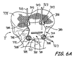
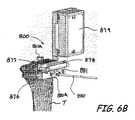
ブロック276における器具の選択は、同一又は等価なタスクを実施できる複数の異なるツール及び器具の特徴、ならびに各ツール及び器具を利用するための処置を文書化できる外科手術技術ガイドを含み得るデータベースを利用することも含み得る。このように、ブロック277において、器具は繰り返して選択することができ、この場合、第一の器具は計画プロセスにおいて外科医の好ましい出発点に基づいて選択される。例えば、外科医は、全膝関節置換処置において最初の切除を受けるためにより好適な条件にあることを判断することができる。外科医はその決断を骨の状態などの様々な因子に基づくことができる。外科医は、伸展、屈曲、前皮質、膝蓋、アライメント(肢又は骨)及び組織バランスも考慮して、膝の処置においてインプラントの位置決定をすることができる。データベースは次いで、図6Aの患者に特異的な脛骨切除ガイド700、図6Bのセンサに基づく脛骨切除ガイド800、従来の脛骨切除ブロック又は同種のものなどの脛骨切除を実施するために利用可能な様々なオプションで外科医に指示することができる。外科医は次に、どの器具が特定の患者に最も適しているかを決断することができる。例えば、外科医は、利用可能でない患者に特異的な器具又は患者に特異的な器具使用に役に立たない患者の生体構造などの入力に基づいて、センサに基づく脛骨切除ガイド800を選択することができる。データベースはしたがって、遠位大腿骨切除を実施するために好適な器具を提案することができる。図5Aの患者に特異的な大腿骨切除ガイド500、図5Bのセンサに基づく大腿骨切除ガイド600、従来のカットブロック又は同種のものはすべて好適である可能性があるが、特定の患者に関して、センサに基づく脛骨切除ガイドの選択は患者に特異的な大腿骨切除ガイドの使用を不適当又は法外な費用が掛かるものにする可能性もある。いずれにしても、外科医は各ステップで様々な患者パラメータ及び外科医の選好を入力することができ、データベースは、次のステップを実施するための命令とともに実行可能である外科手術計画において他のステップのオプションのリスト、及びそのオプションがなぜ推奨されないかについての説明とともに実行可能でないオプションのリストを作成することができる。データベースは、前記データベースをコンピュータ又は手持ち式デバイスのディスプレースクリーン上で見ることができるように、選択されたソフトウェアプログラムで動作する本明細書中で検討するプロセッサと通信するメモリに記憶させることができる。
Instrument selection in
計画は、記憶されたソフトウェアに基づいて命令を実行するプロセッサ(例えば集積回路又は特定用途向け回路)で実行することができるプログラムを含み得るプロセスを用いて出力できる。計画は次に生体構造の部分(又は非動物対象の非解剖学的部分)を特定する命令をもたらし、及び生体構造のそれらの部分が特定されるか又は対象に集中させる。計画に従って対象上に場所が特定されたら、ドリル又はのこぎりなどの手術器具を配置し、特定された部分に対して固定して、計画した結果を達成することができる。出力計画を様々な方式で記録、印刷、表示又は公開することができる。例えば、前記計画をコンピュータもしくは手持ち式デバイスのディスプレースクリーン上で見ることができるか、又は計画を紙などの物理的媒体に印刷することができるように、計画は選択されたソフトウェアプログラムで動作する前記プロセッサと通信するメモリに記録することができる。 The plan can be output using a process that can include a program that can be executed on a processor (eg, an integrated circuit or an application specific circuit) that executes instructions based on stored software. The plan then provides instructions to identify parts of the anatomy (or non-anatomical part of the non-animal object) and those parts of the anatomy are identified or focused on the object. Once a location is identified on the object according to the plan, a surgical instrument such as a drill or saw can be placed and secured to the identified portion to achieve the planned result. Output plans can be recorded, printed, displayed or published in various ways. For example, the plan runs on a selected software program so that the plan can be viewed on a display screen of a computer or handheld device, or the plan can be printed on a physical medium such as paper. It can be recorded in a memory that communicates with the processor.
例えば、ブロック272で出力された計画に基づいてブロック274においてプロテーゼを選択するか又はプロテーゼを特定することは、どちらもBiomet, Inc.により販売されているVanguard(登録商標)Knee Prosthesis System又はOxford(登録商標)Knee Prosthesis systemを含み得る膝プロテーゼなどの特定の種類のプロテーゼを選択することを含み得る。プロテーゼを選択する際、サイズ、サイズの範囲、選択された構成要素(例えば、モバイルベアリング又は非モバイルベアリング)などの詳細、及びブロック270から決定された計画を達成するための選択されたプロテーゼに関する他の詳細を計画で決定し特定することができる。
For example, selecting a prosthesis or identifying a prosthesis at
様々な実施形態において、計画は、ロッド404(図4B)を大腿骨242中になど、髄内(IM)ロッドを位置決定するための場所を特定することを含み得る。IMロッドの位置は、Biomet, Inc.によって販売されるAscent(登録商標)膝システムを備えた器具などの既知又はあらかじめ決められた器具形状に基づいて決定することができる。IMロッドに関する位置の決定は、図2で示すように、ユーザによる生体構造の決定及び/又は特定された形状にさらに基づいてもよい。さらに、IMロッドの決定された場所は、ブロック272からの選択又は特定された成果に基づくものであってよい。
In various embodiments, planning may include identifying a location for locating an intramedullary (IM) rod, such as rod 404 (FIG. 4B) in
現在入手可能な器具及びプロテーゼはブロック272での計画を達成するために用いられる前記アクセス可能なデータベースに含まれていてもよいと理解される。例えば、図5A及び6Aに示すものなどの患者に特異的な様々な器具、又は図5B及び5Bに示すものなどの様々なセンサ支援器具をブロック272で考慮することができる。例えば、Biomet, Inc.から市販されているSignature(商標)ガイド及びZimmer, Inc.から市販されているiASSIST(商標)ガイドがデータベースに含まれていてもよい。さらに、他のセンサ支援器具、例えばZimmer Biometから市販されているeLibra(登録商標)圧力検出デバイス、ならびに従来の器具がデータベースに含まれていてもよい。圧力検出を備えた動的膝バランサーは、あらゆる目的に関してその全体を参照により本明細書に援用されるFisher氏らの米国特許第8715290号明細書に記載されている。
It is understood that currently available instruments and prostheses may be included in the accessible database used to achieve the plan at
患者及び様々な器具の両方の既知及び/又は記憶された形状、サイズなどを使用して、ブロック230でユーザによって入力された結果を達成することができる。ブロック270で計画を決定しているシステムは、データベースにアクセスして、それらの器具、プロテーゼなどを決定して、ブロック230からのユーザの入力を達成することができる。データベースは、関係が関連付けられたリレーショナルデータベースで検索可能であり得る。データベースは、含まれる器具の各々の外科手術技術も含み得る。
Using the known and / or stored shapes, sizes, etc. of both the patient and the various instruments, the results entered by the user at
したがって、決定された計画272に基づいて、そして大腿骨242内のIMロッド404の選択された位置に基づいて、選択された器具をIMロッド404に対する位置決定のために特定して、ブロック270において決定された計画に基づいて結果を達成することができる。言い換えると、カットガイドなどの器具を、処置の一部を実施するためにIMロッド404上に配置することができるか、又はIMロッド404に接続することができる。あるいは、生物学的特徴などの他のランドマークを髄内ロッド以外の処置を実施するための基準として使用することができる。
Accordingly, based on the
さらに、ブロック272における出力計画は、器具の計画及び/又は器具の設定の選択に基づいて器具を選択することを含み得る。例えば、図7〜17を参照して、4−in−1カットブロック及びサイザーを有する一体型器具10を大腿骨F上に配置することができる。他の例では、4−in−1カットブロックをIMロッド404上に配置することができるか、又はAscent(商標)トータルニーシステムを備えたBiomet, Inc.によって販売されている4−in−1 AP面取りガイドも、器具10の前に選択又は決定された位置でIMロッド404と接続することができる。器具10の操作は、図7〜17を参照して説明する。したがって、出力計画272は、器具10に特有のあらかじめ決められた設定を特定して、ブロック230においてユーザによるあらかじめ選択された入力結果を達成することができる。他の適切な器具、例えばIMロッド404上に配置される場合、遠位切除の量を選択するための切除ブロックなども決定することができると理解される。さらに、又はこれに代えて、患者に特異的又は慣習的な器具、例えば図5Aの患者に特異的な遠位大腿骨切除ガイド500又は図6Aの患者に特異的な近位脛骨切除ガイド700などを出力計画72に基づいて(例えば、ラピッドプロトタイピングによって)生成させることもできる。患者に特異的又は慣習的な器具は、大腿骨F内に配置されたIMロッド404に基づいて、又は患者に特異的なデバイスを介して配置されたピンの使用によって、大腿骨Fに関して配置することもできる。しかしながら、慣習的なインプラント又は器具は、骨及び/又は組織面などの特定の患者の決定された構成にのみ実質的に係合する面を含むように形成することもできる。
Further, the output plan in
したがって、配置されたIMロッド404を使用して、処置を実施するために用いられる様々な器具使用の基準点及び/又は基準場所を特定することができる。計画された場所で大腿骨F内にIMロッド404が配置されていることによって、器具使用及び/又はプロテーゼを大腿骨Fに対して配置して、ブロック272における計画された出力を達成することができる。したがって、所望の可動域又は外反角などの選択された結果を含むブロック230からの入力は、ブロック272における出力である決定された計画に基づいて処置を実施することにより達成することができる。
Thus, the deployed
選択可能性を可能にする他の選択された器具も提供することができると理解される。例えば、ブロック270で決定された計画に基づいて患者に特異的な遠位大腿骨サイザーを生成し製造することができる。患者に特異的なサイザーは、IMロッド404が大腿骨F内に配置されると、IMロッド404上に配置することもできる。患者に特異的なサイザーは、ブロック270で決定された計画に基づいてもよく、また任意の切除前に遠位大腿骨Fと係合するための適切な配向及び/又は接触点を含んでもよい。それにもかかわらず、複数回使用の調節可能なシステム及び/又は単回使用の実質的に患者に特異的なシステムのどちらも、計画276に基づいて選択された器具として使用することができる。
It is understood that other selected instruments that allow for selectability can also be provided. For example, a patient-specific distal femoral sizer can be generated and manufactured based on the plan determined at
さらに、ブロック274からの選択されたプロテーゼは、ブロック230からのユーザ入力に基づく計画270に基づくものであり得る。ブロック274において選択されたプロテーゼは、サイズ、サイズ範囲、及びプロテーゼ構成要素の種類を含み得る。例えば、全膝関節置換について、プロテーゼシステムは、脛骨プラトープロテーゼ、脛骨支持プロテーゼ、及び遠位大腿骨プロテーゼを含み得る。これらプロテーゼ構成要素の各々は複数のサイズで提供することができる。選択された範囲の患者集団(例えば、99%)について適切なサイズを達成するために、様々なサイズの複数の構成要素、例えば3つの構成要素の各々の6つの別個のサイズが必要とされる可能性がある。しかしながら、ブロック270からの計画に基づいて、特定の患者が構成要素の各々の1つ又は2つのサイズの範囲内にあると判定することができる。したがって、選択された構成要素サイズだけを選択された処置に送達することができる。これによって、ユーザによる選択のために最小量の構成要素及び構成要素の清浄化、製造、又は同種のもののための関連もしくは付随する準備及び費用が最小で処置を行うことが可能になる。
Further, the selected prosthesis from
ブロック272における出力計画は、ユーザに対する書面又は電子的に伝達された命令も含み得る。ブロック72における計画の出力は、ユーザに対して、構成要素のサイズの選択された範囲、調節可能な器具システムの設定、及びIMロッド78の提案された設置を特定することができる。図4Aを参照すると、例えば、計画272の出力は前述のように、大腿骨Fの遠位部分と、その上にターゲット又はアクセスロケーション406が表示された図を含み得る。アクセスポイント406の図は、IMロッド404を大腿骨Fに挿入するためのターゲット又は選択されたポイントであり得る。遠位大腿骨の図は、方法220によって作成又はアクセスされる画像データに基づくものであり得る。ブロック272において出力される計画はまた、3Dモデル、3D画像、書面の命令なども含み得る。
The output plan at
したがって、ユーザは、特定の患者に関して、図4Aで図示する出力から標的の位置406を特定することができる可能性がある。標的の位置406は、ブロック230における入力である所望又は選択された結果を達成するためにブロック270で決定された計画の一部として決定される。IMロッド404を次いで患者に挿入して、作成された画像データ及び特定された計画に基づいて計画が実施されることを確実にすることができる。
Thus, the user may be able to identify the
さらに、ブロック272における出力は、決定された特定の設定、再使用できるサイザーの一部の位置を、計画の適切な進行を判定するために含み得る。さらに、計画272の出力は、大腿骨Fの遠位部分の適切な切除及び計画の他の部分を確実にするために用いられるカットブロックの一部を特定することを含み得る。したがって、ブロック272の計画の出力により、ユーザは、決定された計画ブロック270に基づいてブロック230においてユーザによって入力された結果を達成することが可能になり得る。
Further, the output at
計画がブロック272で出力された後、ブロック274で選択されたプロテーゼ、及びブロック276で選択された器具、及び任意の他の選択部分を送達することができる。例えば、計画はブロック210で送達することができ、選択されたプロテーゼをブロック212で送達することができ、そして器具をブロック214で送達することができる。様々な実施形態によると、選択された器具はまた、ブロック216で製造することもできることが理解される。上述のように、器具は、特定の患者(すなわち一人の患者)についてブロック270で出力又は決定された計画に基づいたものであり得る。したがって、器具はブロック270で決定された計画に基づいて製造することができる。これらの器具はブロック276における器具の選択の後にブロック216で製造することができる。しかしながら、器具は患者特有でなくてもよいか、又は患者に特異的である必要はないことが理解される。ブロック272における出力計画は、選択された処置について調節可能である汎用器具の特有の設定(例えばサイズ)を含み得る。様々な実施形態によると、選択されたプロテーゼはさらに、ブロック218で製造又は設計される患者に特異的又は設計されたプロテーゼも含み得ることがさらに理解される。プロテーゼのデータベースがブロック230における入力結果を達成するためのプロテーゼを含まない場合、患者に特異的なものを決定することができる。患者に特異的なプロテーゼは、ブロック218で設計及び製造することができ、次いでブロック212で送達することができる。
After the plan is output at
部分の各々は、電子的伝送、郵便配達、宅配便、又は他の適切な送達システムなどの様々な一般的に知られている技術にしたがって送達することができる。例えば、計画はブロック210で電子的伝送を介して計画プロバイダー、例えばBiomet, Inc.から、Signature(商標)Patient−Specific Systemを組み入れたものをはじめとする公知送達システム又は他の適切な送達システムにより送達することができる。プロテーゼ及び器具は、ブロック212、214で適切かつ概ね公知の技術にしたがって送達することもできる。方法200はその後ブロック220で終了することができる。
Each of the portions can be delivered according to various commonly known techniques such as electronic transmission, postal delivery, courier, or other suitable delivery system. For example, the plan is sent via
しかしながら、ブロック220で方法を終了することは、ブロック270で決定された計画に基づいて患者に関して処置を実施する前に行うことができると理解される。すなわち、計画、プロテーゼ、及び器具がブロック210〜214で送達された後、ユーザは選択された対象、例えばヒト患者に対して、送達されたアイテムを用いて処置を実施することができる。処置を実施する際、ブロック210から送達された計画に従うことができ、ユーザはブロック214から送達された器具を用いてブロック212から送達されたプロテーゼを移植することができる。上述のように、ブロック214から送達された器具を使用して、ブロック270で決定された、ブロック272における計画出力を達成することができる。ブロック212で送達されたプロテーゼは、ブロック270で決定された計画に基づいて、すべての可能なサイズではなく、限定されたサイズ範囲から適切なプロテーゼ部材を選択することを可能にし得る。したがって、ユーザは決定された計画270に基づいて処置を実施して、ブロック230で選択された結果を達成することができる。
However, it is understood that terminating the method at
したがって、概して図1で示した方法は計画を決定して、ユーザによってブロック230で選択及び入力された所望又は選択された結果を達成することができる。ユーザは外科医であり得る。ブロック226における作成したデータ/画像表示とあわせてブロック230からの入力に基づいて、システムはブロック270で計画を決定することができる。計画を決定する際に、システムは既知及び/又は利用可能な器具のデータベースに既知及び/又は利用可能なプロテーゼとあわせてアクセスすることができる。これら既知及び/又は利用可能な器具の各々は既知及び/又は利用可能なプロテーゼとあわせてそれらの既知形状及びサイズを用いて分析して、ブロック230からの入力結果を達成するか又は最もよく達成するブロック270での計画を決定することができる。例えば、入力された所望の結果は選択された可動域(ROM)及び外反角であり得る。システムは次に作成された対象データ及び器具及びプロテーゼのデータベースを分析することができる。システムは次に、どの器具、その器具についてどの特定の設定、そしてどの特定のプロテーゼが入力結果を達成できるかを決定することができる。システムは次に、ブロック270での計画を決定することができ、そして特定され選択された器具、設定、及びプロテーゼを含むブロック272での計画を出力することができる。また、データベースが適切な器具及び/又はプロテーゼを含まない場合、システムは器具及びプロテーゼの設計を決定することができる。このすべては、手術室に対象を入れる前など、処置の開始に先立って行うことができる。したがって、器具及びプロテーゼ選択は外科手術を開始する前に行うことができる。さらに、外科医などのユーザは、選択された結果を入力するだけでよく、システムが結果を達成するための計画を決定する。
Thus, in general, the method shown in FIG. 1 can determine a plan to achieve the desired or selected result selected and entered by the user at
図示した方法200に加えて、様々な器具及びデバイスを使用して処置を支援することができる。例えば、処置を実施するために、遠位大腿骨Fなどの生体構造の一部に対して様々なガイド及びテンプレート器具を配置することができる。様々な実施形態に従って、器具は遠位大腿骨に対して配置することができ、あらかじめ決められた計画に従って調節することができる。例えば、方法200を使用して、上述のものと同様に、ユーザに提供された設定に基づいて遠位大腿骨に対してテンプレート又は器具の特定又は位置決定を支援することができる。
In addition to the illustrated
様々な実施形態に従って、大腿骨Fの遠位部分は、図7〜17で図示した調節可能な大腿骨輪郭ブロックを使用して、図1で示す計画などのあらかじめ決定された計画に基づいて準備又は配向させることができる。一体型器具10は、本明細書中でさらに検討するように、大腿骨Fの遠位部分を含む大腿骨Fに対して配向させることができる。概して、一体型器具10は、大腿骨及び/又は大腿骨Fの部分に対して配置される様々な部分を配向させるために大腿骨Fに対して調節することができる。例えば、遠位、近位、後部切除、及び同種のものを含む大腿骨の様々な切除を実施するために、ロッド又はドリルホールを大腿骨Fに形成することができる。
In accordance with various embodiments, the distal portion of femur F is prepared based on a predetermined plan, such as the plan shown in FIG. 1, using the adjustable femoral contour block illustrated in FIGS. Or it can be oriented. The
図3は、図1で示すフローチャートに従って少なくとも部分的に計画することができるような処置を実施する方法300を示すフローチャートである。方法300は、患者の骨の三次元モデルを作成することができるブロック302から開始することができる。上述のように、外科手術計画は患者様データ、MRI、CT又はX線入力を含む患者データに基づいて1以上の3Dモデルを作成することができるか、又は単にX線入力なしで患者様データに基づく命令に基づくことができる。3Dモデルにより、ブロック304で患者のサイズ設定が少なくともある程度可能になり得る。同様に、患者様データを使用して、患者のサイズ設定を少なくともある程度行うことができる。言い換えると、サイズ設定は正確である必要はないが、サイズをある程度狭めるのに有用であり得る。3Dモデルは、例えば図4Aを参照して記載するように作成することができる。
FIG. 3 is a flowchart illustrating a
ブロック306で、サイズ設定した骨に基づいた外科手術計画の部分を本明細書中で記載するように記録することができる。ブロック308及び310は、図1のブロック276及び277を参照して前述した手術器具及びツールを選択する反復プロセスを示す。ブロック312で、選択されたツール及び器具の一部又は全部を外科手術に先立って密封された滅菌容器中にパッケージすることができる。このように、図1中のブロック214を参照して記載されているように、パッケージした手術道具及び器具を送達することができる。
At block 306, a portion of the surgical plan based on the sized bone can be recorded as described herein.
一旦外科手術が始まったら、大腿骨Fをブロック314で切除することができ、そして脛骨Tをブロック316で切除することができる。しかしながら、他の例又は処置では、脛骨Tを最初に切除することができ、大腿骨Fを二番目に切除することができる。
Once surgery has begun, femur F can be excised at
ブロック314では、大腿骨Fの切除は、Signature Guide(例えば、図5A中の切除ガイド500)、標準的器具又はi−Assist(例えば、図5B中の切除ガイド600)によって達成することができる。センサ支援器具の利点は、外科手術時に大腿骨頭部中心を見ることができない場合に大腿骨頭部中心を決定できることである。さらに、患者のASIS(上前腸骨棘)間の距離がわかっている場合、頭部中心間の距離は、確立された情報から、例えばRitter氏らの特許を参照して上述された技術を使用することによって確立することができる。
At
また、対側頭部中心は、センサによって、例えば図2のセンサ252A〜252Cを使用することによって得ることができる。また、これらの寸法は、身長及び体重のような患者データ又は他の詳細、例えば擬人化データによって推定することができる。患者の対側頭部中心距離及び肢の長さを知ることで(頭部中心から足首までの関節線(joint line)を測定又は推定することができる)機械軸線からの運動学的(実際の)関節線角度を得ることができる(頭部中心距離の半分を肢の長さで割ることによって、基本的に運動学的角度の正接を得る)。さらに、図2のセンサ252A〜252Cを使用することができる。脛骨T及び大腿骨F及び膝関節を屈伸させて運動軸線を決定することができる。この角度を知ることで、全ての関節線配向について一貫した切断の配向が可能になり(機械軸線からの角度を伸展及び屈曲において大腿骨で、及び脛骨で再現することができる)、患者に特異的であり得る。
The contralateral head center can be obtained by using a sensor, for example, the
ブロック315で、大腿骨Fをサイズ設定することができる。一例において、図7〜17を参照して記載する調節可能な輪郭ブロックである一体型器具10を、遠位大腿骨切除を実施した後に使用することができる。一体型器具10のサイズの範囲は、計画から、例えば3Dモデルから、又は患者様データから決定することができ、実際のサイズは外科手術中に決定される。一体型器具10を使用して、図7〜17を参照して記載するように、遠位切除を実施した後、外科手術で大腿骨Fを具体的にサイズ設定及び配置することができる。さらなる特徴は、屈曲について伸展で決定した関節線配向(運動学的又は垂直)を使用して一体型器具10を配向させるのに役立てることができることである。これは、手作業で設定した較正であり得るか、又は潜在的に遠位又は脛骨センサと対をなしたセンサを使用することができる。
At
組み込み式の調節可能な内側/外側幅ゲージを一体型器具10の別の例に一体化させることができる。例えば、内側シム48及び内側足部52は、内側/外側幅を一体型器具10上に提供されたスケールから読み取ることができるように、外側シム50及び外側足部54に対して調節可能に配置された構成にすることができる。あるいは、差し込み式の内側/外側幅チェッカーを受けるために一体型器具10中に空間を含めることができる。内側/外側幅は大腿骨Fのサイズ設定の間の検討事項として重みづけすることができる。
A built-in adjustable inner / outer width gauge can be integrated into another example of the
ブロック316で、脛骨Tは外科手術の間に切除することができる。この切除は、Signature Guide(例えば、図6A中の切除ガイド700)、標準的器具又はi−Assist(例えば、図6B中の切除ガイド800)によって達成することができる。切除は、運動学的又は内側/外側方向で機械軸線に対して垂直であり得、垂直又は前/後方向で様々な後方傾斜であり得る。
At
ブロック318で、大腿骨及び脛骨切除は、ディストラクタデバイス、例えば図18のディストラクタ器具900又は別のデバイスによって互いに対して配置することができる。これは、非較正又は較正されたデバイスであり得、eLibraデバイス又はOrthoSensorデバイスなどの本明細書中で記載する市販品を含み得る。このチェックは、外科医及び患者の詳細に応じて、軟組織修飾、骨切除変更を可能にするか、又は単なる基準であり得る。
At
また、計画及び外科手術詳細から機械的アライメントを知ることによって、患者データに基づいた詳細を構成する配向が可能になり得る。1回の骨切除の後にディストラクタを使用して別のものを配置することでも、相対的配向及び距離を設定することが可能になり得る。さらに、較正された伸延(デバイス又はセンサ)は内側/外側負荷の構成を明らかにすることができる。50°o/50°o分割よりもむしろ、負荷を60°o/40°oに分割してもよい(又は身体計測データに基づいて50/50〜70/30のような範囲にすることが望ましい可能性がある)。それはさらには、一方の顆を制御し、他方追従させ伸延を行うことができ、アライメント(又はある他の生体構造基準)により組織バランスならびに切断配向及び位置を設定することが可能になることを意味する。これによって、アライメント、バランス及び場所の評価(潜在的に屈曲及び伸展において)によって適切な切除を決定することを効果的に可能にする可能性がある。そして、切断を全体的なアライメントに基づいて再検討することができ、腰の中心から足首までのラインが膝大腿部の内側/外側顆接点内である場合、これは軟組織バランスなしで潜在的、本質的に安定であることが認められる。 Also, knowing the mechanical alignment from the plan and surgical details may allow orientations that make up the details based on patient data. Placing another using a distractor after a single bone resection may also allow the relative orientation and distance to be set. Furthermore, a calibrated distraction (device or sensor) can reveal the configuration of the inner / outer load. Rather than dividing 50 ° o / 50 ° o, the load may be divided into 60 ° o / 40 ° o (or in a range such as 50/50 to 70/30 based on anthropometric data) May be desirable). It also means that one condyle can be controlled and the other can be followed and distracted, and alignment (or some other anatomical standard) can set tissue balance and cutting orientation and position. To do. This may effectively allow the appropriate ablation to be determined by alignment, balance and location assessment (potentially in flexion and extension). The amputation can then be reviewed based on the overall alignment and if the line from the center of the waist to the ankle is within the medial / lateral condyle junction of the knee femur, this is potentially without soft tissue balance. It is recognized that it is inherently stable.
第一の切除が、例えば大腿骨Fに対して実施された後、以下の方法を使用して同等でない内側及び外側間隙又は等しくない軟組織負荷で伸長又は屈曲空間を創出することができる。関節腔を次いで内側及び外側軟組織に対して等しい負荷を加えて緊張させることができる。例えば脛骨Tに対して第二の骨切断を、第一の切断に対して非平行に行うことができ、その結果、側方関節腔に比べて小さな(又は大きな)内側関節腔を得ることができる。 After the first resection is performed, for example, on the femur F, the following method can be used to create a stretch or flex space with unequal medial and lateral gaps or unequal soft tissue loads. The joint space can then be tensioned with equal load on the medial and lateral soft tissues. For example, a second bone cut can be made to the tibia T non-parallel to the first cut, resulting in a smaller (or larger) inner joint space compared to the side joint space. it can.
脛骨Tのサイズ範囲は前述の計画で決定することができる。計画は、実際に外科手術を少なくともある程度実施するために必要なサイズを減少させる。また、外科手術計画は脛骨Tの切除ガイドの配向を明らかにするのに役立つ可能性がある。 The size range of the tibia T can be determined by the aforementioned plan. The plan actually reduces the size required to perform at least some of the surgery. The surgical plan may also help to reveal the orientation of the tibial T resection guide.
ブロック320及び322において、インプラントはブロック314〜318から決定される情報及び外科手術計画に基づいて選択することができ、続いて通常の方法で移植又は導入することができる。 In blocks 320 and 322, an implant can be selected based on the information determined from blocks 314-318 and the surgical plan, and subsequently implanted or introduced in the usual manner.
図4Aは、三次元モデル化された近位脛骨400及び遠位大腿骨402の概略図である。図4Bは髄内ロッド404が挿入された脛骨T及び大腿骨Fの略図である。
FIG. 4A is a schematic view of a three-dimensional modeled
一例において、モデル化された近位脛骨400及び遠位大腿骨402は、あらゆる目的についてその全体を参照により本明細書に援用されるMahfouzの米国特許第8884618号明細書に記載されているシステム及び方法を用いて三次元モデル化することができる。脛骨400は脛骨Tの三次元モデルであり得、大腿骨402は大腿骨Fの三次元モデルであり得る。大腿骨Fは大腿骨242であり得、脛骨Tは脛骨243であり得、これから図2を参照して外科手術計画を開発した。
In one example, the modeled
実際のインプラント設置が骨に対して画定される前に計画を立てる。それには、インプラントの最終的な位置が患者に特異的なランドマークに対してどこにあるかを対話形式で決定することが含まれる。脛骨T、大腿骨F、モデル化された近位脛骨400及び/又はモデル化された遠位大腿骨402上のランドマーク(硬又は軟組織又は軸線、例えば大腿骨上顆)を特定するなど、ランドマークは、計画中に特定することができる。最終的な位置には、どのようにインプラントを配置して、患者の骨の選択され計画された軸線、可動域、及びプロテーゼ移植後の他の選択された結果を達成するかが含まれ得る。それはまた、対象又はデバイスに対する任意の適切又は選択された部材の位置決定も含まれ得る。計画は、プロテーゼ設置に至る切除準備に基づく様々な結果(例えば内反及び外反角)を含み得る。計画は、上述のものを含む選択されたソフトウェアプログラムで動作するプロセッサによって実行することができる。さらに、計画は、X線画像を評価し、ランドマークの特定及び計画の開発のために使用することができる2Dテンプレートを構築することによって決定することができる。
Plan before the actual implant placement is defined for the bone. It involves interactively determining where the final position of the implant is relative to the patient specific landmark. Lands such as identifying landmarks (hard or soft tissue or axis, such as the epicondyle of the femur) on the tibia T, femur F, modeled
プロテーゼの設置及び移植などの処置の間、図2を参照して記載するように、計画の作成及び決定で使用した同じ基準又は解剖学的ランドマークを骨上で特定するのが望ましい及び/又は必要である場合がある。切除などの処置が計画と合致していることを確実にするために、計画によって特定又は使用されるランドマークを処置の間に特定してもよい。これらには、(硬もしくは軟組織又は軸線、例えば大腿骨上顆)を配置することが含まれ得る。ランドマークは適切な切除及び/又はガイド設置のために使用することができる。したがって、処置の間に、ランドマークの特定及び設置を行うことができ、患者の骨又は他の適切な生体構造に関する位置特定(登録)と称する場合がある。 During procedures such as prosthesis placement and implantation, it may be desirable to identify on the bone the same criteria or anatomical landmarks used in planning and determination as described with reference to FIG. May be necessary. To ensure that a procedure, such as ablation, is consistent with the plan, landmarks identified or used by the plan may be identified during the procedure. These may include placing (hard or soft tissue or an axis, such as the epicondyle of the femur). The landmark can be used for proper excision and / or guide placement. Thus, landmarks can be identified and placed during the procedure, sometimes referred to as location (registration) with respect to the patient's bone or other suitable anatomy.
遠位大腿骨プロテーゼ設置などの一例において、IMロッド404は、解剖学的軸線(IM管)を示し、かつ概して2本の軸線で器具の安定なプラットフォームを提供する大腿骨上の1つの基準又はランドマークであり得る。IMロッド404はX軸及びY軸の両方でものを安定化させることができるが、Z(回転)軸では安定化させることができない。他のランドマークは、遠位大腿骨後顆を含んでもよく、これはIMロッド404と組み合わされて回転基準を与える。Z基準は最も遠位の大腿骨顆をガイド部分と接触させることができる。別の基準は大腿骨の前皮質であり得る。脛骨に関して、基準は脛骨の前面又は脛骨結節のいずれかの側面を含み得る。大腿骨(又は脛骨)の幅も使用することができる。脛骨又は遠位大腿骨のいずれかの関節軟骨最下(最薄)点をチェックすることは有用であり得る。これらの基準が特定されたら、計画から患者に特異的なパラメータをそれらに対して適用することができる。これらの基準によって、計画と同じ基準により骨に対して器具を配置することが可能になり、その後、動かないように固定する。器具は、本明細書中で検討するように、患者に特異的な部分又は部材(針、患者に特異的なキー又は部材、患者に特異的な設定、又は器具を特定の設定に変更することができるプログラム可能もしくはプログラムされた部分を含む)も含むことができ、他の器具部分中に挿入するか、他の器具部分に取り付けるか、又は他の器具部分に対して調節して計画と同じようにインプラントを配向させる位置にガイドをセットすることができる。あるいは、患者に特異的な部分又は設定は、他の器具部分を配置し固定する前に適用することができる。
In one example, such as a distal femoral prosthesis placement, the
ランドマークを配置したら、本明細書中でさらに検討するような器具及び/又はガイドを、ランドマークに配向させるか又はランドマーク上に設置するか及び/又はランドマークと整列させることができる。したがって、器具の位置決定は計画に基づいて行うことができる。上述のように、特定されたランドマークを使用して、骨の成形を促進して計画に一致したプロテーゼの配置を行うように、ドリル又はカットガイドなどの器具を配向させることができる。したがって、ガイド及び器具を計画に基づいて配向させて、選択された結果を達成することができる。 Once the landmark is in place, instruments and / or guides as discussed further herein can be oriented to the landmark or placed on and / or aligned with the landmark. Therefore, the position of the instrument can be determined based on the plan. As described above, the identified landmarks can be used to orient an instrument, such as a drill or cut guide, to facilitate bone formation and conform to a planned prosthesis placement. Thus, guides and instruments can be oriented based on a plan to achieve selected results.
図5Aは患者に特異的な遠位大腿骨切除ガイド500の斜視図である。典型的な患者に特異的な遠位大腿骨切除ガイドは、あらゆる目的のためにその全体を参照により本明細書に援用されるMetzger氏らの米国特許第8591516号明細書に記載されている。 FIG. 5A is a perspective view of a patient specific distal femoral resection guide 500. A typical patient-specific distal femoral resection guide is described in US Pat. No. 8,591,516 to Metzger et al., Which is hereby incorporated by reference in its entirety for all purposes.
図5Aを参照して、本教示による典型的な患者に特異的な大腿骨アライメントガイド500が、患者の対応する遠位大腿骨F上に取り付けられて示されている。大腿骨アライメントガイド500は、相補的であり、上述のように手術前の計画に基づいて患者の大腿骨Fの前遠位面584の一部とぴったりと合い、係合するように作られた患者に特異的な係合面502を有する軽量体501を有し得る。例えば、係合面502は面584の鏡像であり得る。大腿骨アライメントガイド500は、窓/開口部504ならびに対応する遠位アライメントピン520を案内するための案内ボア507を画定する第一及び第二遠位案内構造506を含み得る。大腿骨アライメントガイド500はまた、対応する前アライメントピン522を案内するための案内ボア509を画定する第一及び第二前案内構造508も含み得る。
With reference to FIG. 5A, a typical patient-specific femoral alignment guide 500 in accordance with the present teachings is shown mounted on the corresponding distal femur F of the patient. The femoral alignment guide 500 is complementary and made to fit and engage a portion of the anterior
大腿骨Fに取り付けた大腿骨アライメントガイド500の有無にかかわらず、ピン520及び522を使用して他の患者に特異的なガイドを大腿骨Fに正確に(in a precise matter)取り付けることができるように、ピン520及び522は大腿骨Fに残留したままにすることができる。例えば、遠位切断ブロック(図示せず)を、前アライメントピン522上に取り付けることができ、前アライメントピンは遠位切断ブロックの対応する開口部を通過することができ、その間、大腿骨アライメントガイド500は依然として遠位大腿骨F上にある。アライメントガイド500は使い捨て可能であり、のこぎりで切るか又は切断することもできるポリマー材料で作製することができる。遠位切断ブロックは切断スロット又は他の切断案内構造を含み得る。カッティングブレードは切断スロットによって案内することができ、アライメントガイド500及びアライメントピン520によってのこぎりで切断する大腿骨Fの遠位切除を行い、切除した遠位面を得ることができる。
With or without the femoral alignment guide 500 attached to the femur F, the
図5Bはセンサ支援遠位大腿骨切除ガイド600の斜視図である。典型的なセンサ支援遠位大腿骨切除ガイドは、あらゆる目的に関して参照により本明細書に援用されるAmiot氏らの米国特許第8265790号明細書で記載されている。
FIG. 5B is a perspective view of a sensor assisted distal
切除ガイド600はトラッカー部材602を含むことができ、これはピン又は留め具などの任意の好適な手段により大腿骨Fに別々に固定することができる。トラッカー部材602は、大腿骨Fの位置決定における配向変化を検出する微小電気機械センサ(MEMS)、ジャイロスコープ、加速度計又は同種のもの、トラッカー部材602及び/又は切除ガイド600、及び切除ガイド600を大腿骨Fと整列させる際に外科医に出力を提供するものなどの様々なポジションセンサを含み得る。切除ガイド600を、トラッカー部材602からの任意のデータを用いて配置することができるピン604によって大腿骨Fに固定することができる。好適なパラメータが得られたら(例えば、内反−外反、屈曲−伸延など)、切除ガイド600を大腿骨Fに、例えばピン604を使用して固定することができる。続いて、スロット606を使用して、大腿骨Fの遠位切除を行うためののこぎりなどの切除道具と合わせて使用することができる。
The
図6Aは患者に特異的な近位脛骨切除ガイド700の斜視図である。典型的な患者に特異的な近位脛骨切除ガイドは、あらゆる目的のためにその全体を参照により本明細書に援用されるMetzger氏らの米国特許第8591516号明細書に記載されている。 FIG. 6A is a perspective view of a patient specific proximal tibial resection guide 700. A typical patient-specific proximal tibial resection guide is described in US Pat. No. 8,591,516 to Metzger et al., Which is hereby incorporated by reference in its entirety for all purposes.
図6Aを参照して、各々の脛骨アライメント/切除ガイド700を本教示に従って示す。脛骨アライメントガイド700は、近位部分703、前部705及び、相補的であり、手術前の計画に基づいて1つだけの位置で患者の脛骨Tの前面772及び近位面774の一部とぴったり合いかつ係合するように作られた患者に特異的な骨係合面702を有する本体701を含み得る。例えば、係合面702は面772及び774の鏡像であり得る。脛骨アライメントガイド700は対応する近位アライメントピン又は他の留め具723の案内ボア707を画定する第一及び第二近位案内構造706を含み得る。脛骨アライメント/切除ガイド700はまた、対応する前アライメントピン又は他の留め具727の案内ボア709を画定する第一及び第二前案内構造708も含み得る。アライメントガイド一般及び特に大腿骨アライメントガイド500に関連して上述したように、脛骨アライメントガイド700を使用して、対応する近位及び前アライメントピン723、727の基準ホールを穿孔することができ、次に、各切除及び脛骨アライメント/切除ガイド700が除去された後の対応する切除ブロックに必要であれば再挿入することができる。図6Aで示す実施形態において、脛骨アライメント/切除ガイド700は、患者の手術前の計画に従って脛骨切除を案内するための切除案内スロット710を含み得る。脛骨アライメント/切除ガイド700を、脛骨アライメント/切除ガイド700を脛骨Tに取り付けた状態で、案内スロット710を通してブレード又は他の切除道具を用いて切除するための切除ガイドとして任意に使用することができる。
With reference to FIG. 6A, each tibial alignment / resection guide 700 is shown in accordance with the present teachings. The tibial alignment guide 700 is complementary to the
図6Bはセンサ支援近位脛骨切除ガイド800の斜視図である。典型的なセンサ支援近位脛骨切除ガイドは、あらゆる目的に関して参照により本明細書に援用されるAmiot氏らの米国特許第8265790号に記載されている。
FIG. 6B is a perspective view of a sensor assisted proximal
切除ガイド800は、脛骨Tにしっかりと固定することがベース876を有し得る。切断ガイド877は、ピボットジョイントによりベース876に枢動可能に取り付けることができる。切断ガイド877は、その中にブレードを挿入して脛骨T上で切断を実施するスロット878を有し得る。MEMSユニット879は、切断計画の配向を追跡するように切断ガイド877と一体であり得、そして三自由度追跡を提供して、切断ガイド977の配向と関連した追跡データを提供する。切除ガイド800は、第一ネジ棒880によって骨に固定することができる。ノブ880Aを用いて所望の内反−外反配向に達したら、内反−外反配向で骨にベース876を固定するようにロッド881を使用する。脛骨Tに関して切断計画を作成することを考慮して、切断ガイド877の所望の配向に達するようにノブ881Aを使用して屈曲−伸延配向を調節する。切除ガイド800中のスロット878の形状の関数として仮想切断計画を追跡できることが指摘されている。更に具体的には、MEMSユニット875に、第二の切断計画と追跡して骨上のインプラントの位置決定をシミュレートすることができるように、切断計画を表すデータを提供することができる。
The
図7は、調節可能な4−in−1カットブロック12及び調節可能なサイザー14の一部を有する関節形成計画のための一体型器具10の斜視図である。図8は、調節可能な4−in−1カットブロック12及び調節可能なサイザー14を示す図7の一体型器具10の分解図である。図7及び8を同時に説明する。調節可能なサイザー14は典型的には、図14を参照して後述するように、大腿骨の後方部分の接触を提供する針とともに使用する。
FIG. 7 is a perspective view of an
調節可能な4−in1カットブロック12は、前部カットガイド16、後部カットガイド18、面取りブロック20及び第一アジャスターノブ22を含み得る。調節可能なサイザー14は、シムボディ24、アジャスター体26、足体28、第二アジャスターノブ30及び第三アジャスターノブ32を含み得る。
The adjustable 4-
前部カットガイド16及び後部カットガイド18は、第一アジャスターノブ22を使用して調節可能なポスト34の周りのそれらの相対的位置を調節するように構成することができる。前部カットガイド16及び後部カットガイド18は、前部カットスロット36及び後部カットスロット38をそれぞれ含み得る。面取りブロック20は、調節可能なポスト34に取り付けることができ、前部面取りスロット40及び後部面取りスロット42を含む。調節可能なポスト34は前部ポスト44及び後部ポスト46を備える。
The
前部及び後部カットスロット36及び38は、切断デバイス、例えばのこぎりブレードを大腿骨顆の前部及び後方部分とアライメントさせて、骨の前部及び後部切除を行うのを促進するように構成することができる。前部及び後部面取りスロット40及び42は、切断デバイス、例えばのこぎりブレードを大腿骨顆の前部及び後方部分とアライメントさせて、前部及び後部切除と事前に行った遠位大腿骨切除との間に面取り切除を行うことを促進するように構成することができる。図9〜13を参照してさらに詳細に後述するように、第一アジャスターノブ22は、調節可能なポスト34の前部ポスト44及び後部ポスト46と係合して、前部カットガイド16と後部カットガイド18との間の距離を制御することができ、これは、それらの間に位置する固定場所に対して設定することができる。
Anterior and
第二アジャスターノブ30は、アジャスター体26を使用してシムボディ24と足体28との間の距離を調節するように構成することができる。第三アジャスターノブ32は、アジャスター体26を使用してシムボディ24と足体28との間の角度関係を調節するように構成することができる。
The
シムボディ24は、内側シム48及び外側シム50を含むことができ、これらは後部カットスロット38中に挿入されるように構成することができる。足体28は内側足部52及び外側足部55を含むことができ、これらは脛骨又はその上に配置されたスペーサーの近位端、ならびに後部大腿骨と係合するように構成することができる。大腿骨生体構造に対する切断の相対的な位置に関して、図14〜17を参照してさらに詳細に後述するように、第二アジャスターノブ30はスライドピン56中のノッチに係合して、シム48及び50と足部52及び54との間の距離を調節し、第三アジャスターノブ32はタブ58中のスロットと係合して、例えば枢着点59でのシム48及び50と足部52及び54との間の角度関係を調節することができる。
The
図9は、本体60に接続された前部カットガイド16、面取りブロック20及び後部カットガイド18を示す図8の調節可能な4−in−1カットブロック12の分解斜視図である。図4は、駆動ピン70及び本体60とアライメントさせた第一アジャスターノブ22を示す図8の調節可能な4−in−1カットブロック12の分解側面図である。図9及び10を同時に説明する。
FIG. 9 is an exploded perspective view of the adjustable 4-in-1
前部カットガイド16、後部カットガイド18及び面取りブロック20を本体60に取り付けることができる。本体60は基準点として作用することができ、基準点から前部カットガイド16、後部カットガイド18及び面取りブロック20の動きは関連づけられる。本体60は面取りブロック20中のソケット64A及び64B中にはめ込まれたウィング62A及び62Bを含んでその間の相対的回転を防止することができる。幅、深さ及び厚さを含むウィング62A及び62Bならびにソケット64A及び64Bの特定のサイズは、デバイスの異なる例で変わり得る。本体60はその中に後部ポスト46が挿入されるボア66も含み得る。後部ポスト46はその中に前部ポスト44が挿入されるボア68を含んで調節可能なポスト34を形成することができる(図2)。前部面取りスロット40及び後部面取りスロット42は、図10中の面取りブロック20を通って延びる幻像(phantom)で見ることができる。
The
第一アジャスターノブ22は、駆動ピン70に接続することができ、これは、面取りブロック20(図13で見ることができるとおり)を通過して本体60(図11で見ることができるとおり)中に挿入されて前部ポスト44及び後部ポスト46(図12で見ることができるとおり)と連結される。
The
図11は、図8の調節可能な4−in−1カットブロック12の部分組立図であり、面取りブロック20及び第一アジャスターノブ22を駆動ピン70から除去して、本体60内に配置されたそれぞれ前部及び後部カットガイド16及び18のポスト44及び46を示し、調節可能なポスト34を形成する。前部ポスト44は前部指部72を含むことができ、そして後部ポスト46は後部指部74を含むことができる。
FIG. 11 is a partial assembly view of the adjustable 4-in-1
後部ポスト46は、カットアウト76を含んで、指部72を収容できる。同様に、本体60はカットアウト78(図9)を含んで指部72及び指部74を収容することができる。本体60のカットアウトは、駆動ピン70によって作動させた場合に指部72及び74が平行移動するスロット80に接続することができる。
The
本体60におけるチャンネル86Aに接続するノッチ84Aと突起82Aをアライメントすることによって、駆動ピン70を本体60に挿入することができる。本体60はまた、突起82B(図12)と係合するためにノッチ84B及びチャンネル86Bも含み得る。ノブ22内の相補的ボア89(図9)中にシャフト88を挿入することにより、駆動ピン70を第一アジャスターノブ22(図10)に連結することができる。ピン又は他の留め具91(図9)を、シャフト88中のノブ22及びホール90を通して挿入して、駆動ピン70とノブ22との間の相対的回転運動を防止することができる。ばねをシャフト88の周りに配置して、ノブ22を駆動ピン70から離れるように付勢することができる。したがって、器具10のオペレーターによるノブ22の回転は、駆動ピン70を回転させることができ、これは次に、本体60から比例的に離間したままで、ポスト44及び46を互いに引き寄せられるか又は遠ざかるようにすることができる。
The
図12は、図8の調節可能な4−in−1カットブロック12の部分組立図であり、面取りブロック20を除去して、駆動ピン70のそれぞれスロット92、94内に配置されたポスト44、46の指部72、74を示す。図12はまた、駆動ピン70の突起82Bを示す。
12 is a partial assembly view of the adjustable 4-in-1
駆動ピン70はポスト44及び46を動くようにするためのカム歯車として動作することができる。図9からわかるように、駆動ピン70のシャフト88を通って延びる中心軸線の周りの回転が指部72及び74の直線運動を起こすことができるように、スロット92及び94を不規則な形状にする。スロット92及び94を異なって成形して、異なる移動速度のポスト44及び46を製造することができる。
The
駆動ピン70が回転する際、突起82A及び82Bは本体60のチャンネル86A及び86B内に駆動ピン70を保持することができる。駆動ピン70は、類似の突起及びチャンネル接続を使用して面取りブロック20内に保持され得る。
As the
図13は、面取りブロック20から分解した駆動ピン70の斜視図であり、面取りブロック20のアライメントタブ96A及び駆動ピン70のアライメントスロット98A及び98Bを示す。アライメントタブ96Aがアライメントスロット98Aと係合するように、駆動ピン70を面取りブロック20のチャンバー100に挿入することができる。同様に、チャンバー100内のアライメントタブ96Aの反対のアライメントタブ96B(図示せず)はアライメントスロット98Bと係合することができる。スロット98A及び98Bはチャンバー100内のピン70の回転を可能にすることができるが、完全に係合した場合は軸方向運動を制御することもできる。図10からわかるように、スロット98A及び98Bはピン70の両端からのそれらの距離を変えて、面取りブロック20を本体60に対して動かし、その一方で、突起82はピン70を本体60に対して固定した状態に保持する。さらに、ピン70を面取りブロック20中に完全に固定して、ノブ22を突起82A及び82Bに連結して、駆動ピン70のチャンバー100からの軸方向変位をさらに防止することができる。
13 is a perspective view of the
図8を参照して、さらに詳細に後述するように、ノブ22の回転は、前部カットガイド16及び後部カットガイド18を面取りブロック20から伸縮させることができる。一例において、ノブ22の右回転は前部カットガイド16及び後部カットガイド18を面取りブロック20から遠ざけてより大きな大腿骨のより広い前部及び後部切除を可能にし、一方、ノブ22の左回転は、前部カットガイド16及び後部カットガイド18を面取りブロック20に引き寄せて、より小さな大腿骨のより狭い前部及び後部切除を可能にすることができる。前部カットガイド16及び後部カットガイド18を所望の場所に位置決定したら、前部面取りスロット40及び後部面取りスロット42をさらに適切に、例えば前部カットガイド16と後部カットガイド18との間に位置決定して、大腿骨の面取り切除を可能にすることができる。
As will be described later in more detail with reference to FIG. 8, the rotation of the
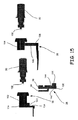
図14は図8の調節可能なサイザー14の分解斜視図であって、シムボディ24、アジャスター体26及び足体28、ならびに第二アジャスターノブ30及び第三アジャスターノブ32を示す。図15は図8の調節可能なサイザー14の分解側面図であって、第二アジャスターノブ30と足体28中のカラー102とのアライメント、及び第三アジャスターノブ32とシムボディ24中のカラー104とのアライメントを示す。
FIG. 14 is an exploded perspective view of the
シムボディ24はまた、内側シム48、外側シム50、保持タブ110、ノブチャンバー112及びピンボア114も含み得る。アジャスター体26はまた、スライドピン56、タブ58、枢着点59、ノッチ116、スロット118及びストップ120も含み得る。足体28はまた、内側足部52、外側足部54、ピボット孔126及びノブチャンバー128も含み得る。第二アジャスターノブ30は指部130を含み得、そして第三アジャスターノブ32は指部132を含み得る。
The
アジャスター体26をシムボディ24に、例えばスライドピン56をピンボア114に挿入することによって連結させることができる。さらに、シムボディ24上のノッチ134はアジャスター体26上のタブ136(図15)を受けることができる。このため、シムボディ24は、長手方向又は直線方向にアジャスター体26に対して平行移動するように構成することができる。
The
足体28は、アジャスター体26に、例えば枢着点59をピボット孔126に挿入することによって連結させることができる。枢着点59は、互いに向かって曲がって、ピボット孔126にフランジ上を通過させることができるフランジを有する一対の対向するタブを備えることができる。足体28を前進させてアジャスター体26と係合させると、フランジが、ピボット孔126からタブが出ていくのを防止できるように、タブは、互いから跳ね返ることができる。そのために、足体28は枢着点59でアジャスター体26及びシムボディ24に対して旋回するように構成することができる。ストップ120は、足体28上の壁138と係合して、旋回量を制限することができる。図のように、枢着点59は中心にあり、足部48及び50の一方を右又は左の膝に使用することができる。他の例では、枢着点59は、調節可能なサイザー14が側方特異的であり得るように、中心から外れている可能性がある。例えば、右側特異的デバイスは足部54に近くずれた枢着点59を有し得、そして左側特異的デバイスは足52に近くずれた枢着点59を有し得る。さらに他の例では、枢着点59のずれは、足部48及び50の一方をそのそれぞれのシムに対して動かすだけで、他方の足部とシムは一定の距離にすることができる。この最後の例は、1つだけの顆からの角度の変化をもたらす可能性がある。
The
完全に組み立てた場合、シムボディ24の面140はアジャスター体26の面142と当接することができ、アジャスター体26の面144は足体28の面146と当接することができる。
When fully assembled, the
図16は、アジャスター体26のスライドピン56と一列に並んだ第二アジャスターノブ30、及びアジャスター体26のスロット118と一列に並んだ第三アジャスターノブ32を示す、図8の調節可能なサイザー14の分解上面図である。図17は、図8の調節可能なサイザー14の部分的に組み立てた図であって、第二及び第三アジャスターノブ30及び32を省略して、第二カラー102内のスライドピン56中のノッチ116、及び第三カラー104内のアジャスター体26のスロット118を示す。
FIG. 16 shows the
指部130をピンボア114中に入れることができるように、第二アジャスターノブ30をノブチャンバー112中に挿入することができる。したがって、指部130はスライドピン56中のノッチ116と係合することができる。図17で示すように、ノッチ116をノブチャンバー112に隣接して配置する。アジャスターノブ30を回転させる場合、指部130はノッチ116中のスライドピン56を押して、シムボディ26をスライドピン56に沿って上下に動かすことができる。ピンボア114内にスライドピン56が閉じ込められているために、これによって、シム48及び50を脚52及び54から遠ざけるか又は近づける方向に動かすことができる。
The
指部132をピンスロット118(図14)中に位置決定できるように、第三アジャスターノブ32をノブチャンバー128に挿入することができる。そのため、指部132はタブ58中のスロット118と係合することができる。図17に示すように、スロット118をノブチャンバー128に隣接して配置する。アジャスターノブ32を回転させると、指部132はスロット118中のタブ58を押して、枢着点59でアジャスター体26に対して足体28を旋回させる。枢着点59の制約以外の足体28に対する制約がないため、これはシム48及び50に対して足部52及び54を曲げさせることができる。例えば、足52はシム48方向に移動することができ、一方、足部54はシム50から離れて移動することができ、枢着点59での足体28の動きの制約のために、逆もまた同様である。
The
図8を参照して、ノブを、器具10の所定の配向又は既知配向に対応し得る位置に固定するために、ノブ22、30及び32は、それらの各ハウジング中のノッチと係合するように構成することができる。面取りブロック20はノブ22の点152と係合できるノッチ150を含むことができる。カラー102はノブ30の点156と係合できるノッチ154を含むことができる。カラー104は、ノブ32の点160と係合できるノッチ158を含むことができる。大腿骨のサイズを決定することができ適切にサイズ設定することができるか又はプロテーゼ構成要素を選択することができるように、ノッチ150、154及び156は既知寸法に対応する可能性がある。
Referring to FIG. 8, in order to secure the knobs in a position that can correspond to a predetermined or known orientation of the
4−in−1カットブロック12及び調節可能なサイザー14を外科手術前プラン又は手術中に開発した計画のいずれかの外科手術計画と合わせて使用して、人工膝インプラントを受けるように患者の大腿骨をサイズ設定することができる。大腿骨をまずサイズ設定したら、4−in−1ブロックを選択することができる。4−in−1カットブロック12を選択することができ、異なるサイズの患者大腿骨を収容するように異なるサイズで構成することができる。4−in−1ブロックを選択する前又は後のいずれかで、内側及び外側顆の遠位部分を含む大腿骨の遠位の大部分を除去することができる。4−in−1カットブロック12を次いで外科手術計画に基づいてサイズ設定して、ノブ22を調節することによりサイズ設定し切除した大腿骨にぴったり合うようにすることができる。
The patient's thigh is used to receive a prosthetic knee implant using the 4-in-1
調節可能なサイザー14を次に組み立てることができる。アジャスターサイザー14は、外科手術計画又は別の設定からの寸法にあらかじめ設定することができる。マルチピースサイザーを使用する場合、前部針を調節可能なサイザー14に組み立てることができる。例えば、あらゆる目的のためにその全体を参照により本明細書に援用されるLorio氏らの米国特許第9050197に記載されているような針を調節可能なサイザー14とともに使用することができる。次に、調節可能なサイザー14を選択された4−in−1カットブロック12と組み立てることができる。
The
一例において、針、調節可能なサイザー14及びカットブロック12をあわせて1つのユニットとして組み立てることができる。他の例では、外科医は、構成要素の2つだけ、例えば調節可能なサイザー14又は調節可能なサイザー14を有する針とカットブロック12とを選択して組み立てることができる。別の例では、カットブロック12を固定された(調節可能でない)バージョンの足部と組み立てることができる。固定されたバージョンの足部は、Lorio氏らの前記特許に記載されている。
In one example, the needle,
調節可能なサイザー14は、シム48及び50を後部カットスロット38に挿入することによってカットブロック12に組み立てることができる。別の例では、カットブロック12に、カットスロットのいずれも詰まらないように、シム48及び50を受けるためのさらなるスロットを提供することができる。例えば、専用のシムスロットを部カットスロット38のすぐ上又はすぐ下に提供することができる。そのような専用のシムスロットは、一貫した後部又は前部切除を有しなくてもよいインプラントシステムで有用であり得、別のアタッチメントにより、足部52及び54又は針がブロックすべてについての1つの部品であることが可能になり得る。次に、後部足部52及び54が後顆に接触し、前部針が前部大腿骨皮質を参照するように、組み立てられた構成要素を遠位大腿骨切除上にはいちすることができる。そのような位置で、アジャスター体26の面142は大腿骨の切除した面に向いている可能性がある。針はこの時、計画と患者の生体構造との間の小さな相違のために適合しない可能性がある。外科医は構成要素を変えることを決めて、適合を評価することができる。
外科医は、ノブ22を調節することによって4−in−1カットブロック12のサイズを変更することができ、これは前部カットガイド16と後部カットガイド18との間の間隙を変更することができる。足部52及び54とシム48及び50との間の後部間隙は、ノブ32を回転させることによって調節することができる。足部52及び54とシム48及び50との間の後部角度はノブ30を動かすことによって調節することができる。上述のように、ノブ22、30及び32の点152、156及び160は、それぞれノッチ150、154及び158と係合して、膝置換処置で用いることができる様々なプロテーゼ構成要素の寸法に対応する既知構成にすることができる。ノブ22、30及び32のいずれか1つ又は任意の組み合わせを調節して、前部及び後部間隙ならびにどのように大腿骨切断が、上顆軸線のような大腿骨ランドマーク、及び脛骨のような他の骨形状と関連するかを評価することができる。これによって、外科医が構成要素(例えばカットブロック12及び調節可能なサイザー14)を除去することなく様々な構成を評価して、患者の生体構造にフィットさせることが可能になる。
The surgeon can change the size of the 4-in-1
一旦サイズ及び位置が決定されたら、カットブロック12を大腿骨にピンで固定することができる。一例において、面取りブロック20においてピンをボア106及び108(図9)に挿入することができる。一旦ピンで固定したら、サイザー14及び前部 針を除去し、切除はスロット36、38、40及び42を通して行うことができる。
Once the size and position are determined, the
切除後、ピンを面取りブロック20から除去し、そして4−in−1カットブロック12を除去することができる。これにより、試験の準備において遠位大腿骨の切除を完了し、そして任意のさらなるステップ、例えば試験用大腿骨構成要素を通して大腿骨構成要素取り付け穴を穿孔し、後部固定大腿骨ボックスの準備を行って処置を完了することができる。
After resection, the pins can be removed from the
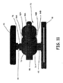
図18は、脛骨アーム904及び大腿骨アーム906を備えることができるディストラクタ器具900を示す。脛骨アーム904はプレート端部908及び制御端部910を含み得る。大腿骨アーム906はプレート端部912及び制御端部914を含み得る。アーム904、906は、ピボットピン916によって提供される支点で互いに接続することができる。ピン916は、例えばヒンジで見られ得るものと類似した配置でアーム904、906においてアライメントされたホール(図示せず)を通って延び得る。脛骨アーム904は本質的に直線状であり得、大腿骨アーム906は制御端部に向かってクランク状に曲げることができる。脛骨プレート918は脛骨アーム908のプレート端部で提供することができる。大腿骨プレート920は大腿骨アーム910のプレート端部で提供することができる。
FIG. 18 shows a distractor instrument 900 that can include a
支点でのアーム間の接続は、アームの制御端部間の距離を減少させるような脛骨アーム904に対する大腿骨アーム906の動きが、プレート端部間の距離を増加させ得るようなものであり得る。同様に、アームの制御端部間の距離を増加させるような脛骨アーム908に対する大腿骨アーム910の動きは、プレート端部間の距離を減少させることができる。
The connection between the arms at the fulcrum can be such that movement of the
概して関節の略外側である方向で切開からアーム908、910が伸びるように、前方切開によってプレートを大腿骨Fと脛骨Tとの間の空間に挿入できるように、そしてプレートをそれらの各アーム上に配置する。アーム908、910は内側外側(medial lateral)軸線に対して正確に平行に伸びる必要はない。
An anterior incision allows the plate to be inserted into the space between the femur F and the tibia T so that the
ディストラクタ器具900を使用して、患者の膝関節を伸延することができる。これは、アーム904、906のプレート端部を互いに近づけ、アーム904、906の制御端部は離間させながら、脛骨及び大腿骨プレート908及び912を切除した脛骨Tと切除した大腿骨Fとの間の空間に挿入することによって達成できる。ばね932によってアームの制御端部間に作用する力に対して、アームに力を加えてそれらの制御端部間の空間を閉じることによって、関節を伸延させることができる。アームの変位を次に、ラチェットステイ922を使用して固定する。さらに、ディストラクタ器具900はアライメントチェックを実施するためにプレート918及び920間の1つ以上のばね934を含み得る。さらに、ディストラクタ器具900は、OrthoSensor, Inc.から市販されているセンサなど1つ以上のセンサ936を含み得る。そのようなセンサはSteinの米国特許公開第2010/0332152号明細書に記載されている。
The distractor device 900 can be used to distract the patient's knee joint. This is because the plate ends of the
本明細書中で記載するシステム、器具及び方法は、インプラントの数及び外科手術を完了するために必要又は要求される器具の数を大幅に抑えることができる。さらに、物流を簡素化するために縮小したセットが利用可能(棚上に保管又はその他)であり得る。 The systems, instruments and methods described herein can significantly reduce the number of implants and instruments required or required to complete a surgical procedure. In addition, a reduced set may be available (stored on a shelf or otherwise) to simplify logistics.
本明細書中で記載する処置の各々のステップで、外科医及び患者の詳細ならびにインプラント及び器具のオプションに基づいて、様々なオプションが利用可能であり得る(外科手術中又は計画前で)。 At each step of the procedure described herein, various options may be available (during surgery or prior to planning) based on surgeon and patient details and implant and instrument options.
様々な記録及び例
実施例1は、全膝関節置換を計画し準備する方法であって、患者の脛骨及び大腿骨の三次元モデルを作製し、三次元モデルに基づく範囲内のサイズを設定し、三次元モデルに基づいて脛骨及び大腿骨の各々について切除道具を選択し、そして切除道具をパッケージングすることを含み得る方法などの主題を含むことができるか、又は使用することができる。
Various Records and Examples Example 1 is a method for planning and preparing a total knee replacement, which creates a 3D model of a patient's tibia and femur and sets a size within a range based on the 3D model. Subject matter can be included or used, such as a method that can include selecting an ablation tool for each of the tibia and femur based on the three-dimensional model and packaging the ablation tool.
実施例2は、実施例1の主題を含み得るか、又は任意に実施例1の主題と組み合わせることができ、患者特異的切除道具及びセンサ支援切除道具から選択される大腿骨及び脛骨切除道具を任意に含んでもよい。 Example 2 can include the subject matter of Example 1 or can optionally be combined with the subject matter of Example 1 to provide a femoral and tibial resection tool selected from patient-specific resection tools and sensor-assisted resection tools It may optionally be included.
実施例3は、実施例1又は2の主題を含むことができるか、又は実施例1又は2の主題と組み合わせることができ、運動データを利用して大腿骨の切除を促進することを備えることを任意に含んでもよい。 Example 3 can include the subject matter of Example 1 or 2 or can be combined with the subject matter of Example 1 or 2 and comprises using motion data to facilitate femoral resection May optionally be included.
実施例4は、任意に、脛骨及び大腿骨上に位置するセンサを使用して運動軸線を決定することを含む、実施例1〜3の1つ又は任意の組み合わせの主題を含むことができるか、又は任意に組み合わせることができる。 Can Example 4 optionally include the subject matter of one or any combination of Examples 1-3, including determining motion axes using sensors located on the tibia and femur? Or any combination.
実施例5は、実施例1〜4のうちの1つ又は任意の組み合わせの主題を含むことができるか、又は任意に組み合わせることができ、任意に、患者の身長、体重、肥満度指数、年齢、性別人種、民族、日常活動及び身体障碍の2つ以上を含む患者の個人データを利用することを含んでもよい。 Example 5 can include the subject matter of any one or any combination of Examples 1-4, or any combination, optionally patient height, weight, body mass index, age Using patient personal data, including two or more of gender, race, ethnicity, daily activity and disability.
実施例6は、実施例1〜5のうちの1つ又は任意の組み合わせの主題を含むことができるか、又は任意に組み合わせることができ、任意に上前腸骨棘データを含む解剖学的データを使用することを含んでもよい。 Example 6 can include the subject matter of any one or any combination of Examples 1-5, or any combination, and optionally anatomical data including superior anterior iliac spine data May be used.
実施例7は、実施例1〜6のうちの1つ又は任意の組み合わせの主題を含むことができるか、又は任意に組み合わせることができ、任意に、調節可能な輪郭ブロックを用いた切除後に遠位大腿骨のサイズ設定をすることを含んでもよい。 Example 7 can include the subject matter of any one or any combination of Examples 1-6, or any combination, optionally after dissection with an adjustable contour block. Sizing the distal femur may also be included.
実施例8は、実施例1〜7のうちの1つ又は任意の組み合わせの主題を含むことができるか、又は組み合わせることができ、任意に、調節可能な内側/外側幅ゲージを用いて遠位大腿骨のサイズ設定をすることを含んでもよい。 Example 8 can include or be combined with the subject matter of one or any combination of Examples 1-7, optionally distal using adjustable inner / outer width gauges. It may also include sizing the femur.
実施例9は、実施例1〜8のうちの1つ又は任意の組み合わせの主題を含むことができるか、又は任意に組み合わせることができ、任意に、ディストラクタデバイスを用いて切除後の大腿骨及び脛骨のアライメントを検証することを含んでもよい。 Example 9 can include the subject matter of any one or any combination of Examples 1-8, or any combination, and optionally a femur after resection using a distractor device And verifying the alignment of the tibia.
実施例10は、実施例1〜9のうちの1つ又は任意の組み合わせの主題を含むことができるか、又は任意に組み合わせることができ、三次元モデルに基づいてまず脛骨切除道具及び大腿骨切除道具の一つを選択し、続いて選択された第一道具に基づいて脛骨切除道具及び大腿骨切除道具を選択することを含む。 Example 10 can include the subject matter of any one or any combination of Examples 1-9, or any combination, and based on a three-dimensional model, first a tibial resection tool and a femoral resection Selecting one of the tools and subsequently selecting a tibial resection tool and a femoral resection tool based on the selected first tool.
実施例11は、実施例1〜10の主題を含むことができるか、又は任意に組み合わせることができ、患者に特異的なデバイスとして切除道具の少なくとも1つを任意に製造することができる。 Example 11 can include the subject matter of Examples 1-10, or can be arbitrarily combined, and can optionally produce at least one of the ablation tools as a patient-specific device.
実施例12は、外科手術を計画し準備する方法などの主題を含むことができるか又は使用することができ、この方法は:1つ以上の骨の三次元骨モデルを作製し、三次元モデルに基づいて1つ以上の骨のサイズ設定をし、三次元骨モデルに基づいて外科手術計画を記録し、外科手術計画に基づいて1つ以上の骨の第一手術道具を選択し、そして第一手術道具の性能パラメータに基づいて第二手術道具の選択を評価することを含む。 Example 12 can include or be used with a subject such as a method of planning and preparing a surgical procedure, which creates a three-dimensional bone model of one or more bones, Sizing one or more bones based on, recording a surgical plan based on the three-dimensional bone model, selecting one or more bone first surgical tools based on the surgical plan, and Evaluating the selection of the second surgical tool based on the performance parameter of the first surgical tool.
実施例13は、実施例12の主題を含むことができるか、又は任意に組み合わせることができ、任意に第一及び第二手術道具をパッケージすることを含む。 Example 13 can include the subject matter of Example 12, or can be arbitrarily combined, and optionally includes packaging the first and second surgical tools.
実施例14は、実施例12又は13の主題を含むことができるか、又は任意に組み合わせることができ、任意にコンピュータ検索可能なコンピュータデータベースを利用して第一手術道具を選択することを含む。 Example 14 can include the subject matter of Example 12 or 13, or can be arbitrarily combined, and includes selecting a first surgical tool utilizing a computer database that is optionally computer searchable.
実施例15は、実施例12〜14の主題を含むことができるか、又は任意に組み合わせることができ、選択された第一手術道具と適合性の選択可能な手術道具のリストに基づいてコンピュータデータベースを使用して第二手術道具を選択することを任意に含んでもよい。 Example 15 can include the subject matter of Examples 12-14, or can be arbitrarily combined, and a computer database based on a list of selectable surgical tools compatible with the selected first surgical tool. Optionally using to select a second surgical tool.
実施例16は、実施例12〜15の主題を含むことができるか、又は任意に組み合わせることができ、身体計測データをさらに含むコンピュータ検索可能なデータベースを任意に含んでもよい。 Example 16 can include the subject matter of Examples 12-15, or can be arbitrarily combined, and can optionally include a computer searchable database that further includes anthropometric data.
実施例17は、実施例12〜16の主題を含むことができるか、又は任意に組み合わせることができ、調節可能な輪郭ブロックを利用して骨のサイズ設定をすることを任意に含んでもよい。 Example 17 can include the subject matter of Examples 12-16, or can be arbitrarily combined, and can optionally include sizing the bone utilizing an adjustable contour block.
実施例18は、実施例12〜17の主題を含むことができるか、又は任意に組み合わせることができ、手術中に上前腸骨棘データを含む解剖学的データを使用することを任意に含んでもよい。 Example 18 can include the subject matter of Examples 12-17, or can be arbitrarily combined, and optionally includes the use of anatomical data including superior anterior iliac spine data during surgery. But you can.
実施例19は、実施例12〜18の主題を含むことができるか、又は任意に組み合わせることができ、1つ以上の骨上に位置するセンサを使用して手術中に運動軸線を決定することを任意に含んでもよい。 Example 19 can include the subject matter of Examples 12-18, or can be combined arbitrarily, and using a sensor located on one or more bones to determine an axis of motion during surgery. May optionally be included.
実施例20は実施例12〜19の主題を含むことができるか、又は任意に組み合わせることができ、患者に特異的なデバイスとして第一及び第二手術道具の少なくとも1つを製造することをさらに含むことを任意に含んでもよい。 Example 20 can include the subject matter of Examples 12-19, or can be arbitrarily combined to further manufacture at least one of the first and second surgical tools as a patient specific device. Including may optionally be included.
これらの非限定的例の各々は、それ自体で自立することができるか、又は様々な配列で組み合わせることができるか、又は他の例の1以上と組み合わせることができる。 Each of these non-limiting examples can stand on its own, can be combined in various arrangements, or can be combined with one or more of the other examples.
前記詳細な説明は詳細な説明の一部を形成する添付の図面に対する言及を含む。図面は、実例として、本発明を実施できる具体的な実施形態を示す。これらの実施形態は本明細書中では「実施例」とも称する。そのような例は、図示又は記載したもの以外の要素を含み得る。しかしながら、本発明者らは図示もしくは記載する要素のみを提供する例も想定する。さらに、本発明者らはまた、本明細書中で図示もしくは記載する他の例(又はその1以上の態様)に関連するかのいずれかである、図示もしくは記載する要素(又はその1以上の態様)の任意の組み合わせ又は配列を用いた例も想定する。 The detailed description includes references to the accompanying drawings, which form a part of the detailed description. The drawings show, by way of illustration, specific embodiments in which the invention can be practiced. These embodiments are also referred to herein as “Examples”. Such examples may include elements other than those shown or described. However, we also envision examples that provide only the elements shown or described. In addition, the inventors also show that the illustrated or described element (or one or more of its elements) is either related to other examples (or one or more aspects thereof) illustrated or described herein. Examples using any combination or arrangement of (aspect) are also envisioned.
本明細書と参照により援用するいかなる文書との間に矛盾する用法がある場合、本明細書における用法が優先する。 In the event of conflicting usage between this specification and any document incorporated by reference, the usage herein shall prevail.
本明細書において、「a」又は「an」という語は、特許文書で一般的である様に、「少なくとも1つ」又は「1つ以上」の任意の他の例又は用法とは無関係に「1つ又は1つ以上」を含むために使用される。本明細書において、「or」という語は、特に別段の記載がない限り、非排他的又は、「A又はB」が「AであるがBではない」、「BであるがAではない」、及び「A及びB」を含むことを指すために用いられる。本明細書において、「含む(including)」及び「そこにおいて(in which)」という語は、「含む(comprising)」及び「ここで(wherein)」という語の各々の平易な英語の等価物として用いられる。また、以下の特許請求の範囲において、「含む(including)」及び「備える(comprising)」という語はオープンエンドである、すなわち、請求項中でそのような語の後に列挙されるもの以外の要素を含むシステム、デバイス、物品、組成物、配合物、又はプロセスがその特許請求の範囲内にあると依然としてみなされる。さらに、以下の特許請求の範囲において、「第一」、「第二」、及び「第三」等という語は、単にラベルとして使用し、それらの対象に対して数値的要件を課すことを意図するものではない。 As used herein, the term “a” or “an” is independent of any other example or usage of “at least one” or “one or more”, as is common in patent documents. Used to include “one or more”. In this specification, unless otherwise specified, the word “or” is non-exclusive or “A or B” is “A but not B” or “B but not A”. , And “A and B”. As used herein, the terms “including” and “in which” are used as plain English equivalents of each of the words “comprising” and “here”. Used. Also, in the following claims, the terms “including” and “comprising” are open-ended, ie, elements other than those listed after such words in the claims. A system, device, article, composition, formulation, or process is still considered to be within the scope of the claims. Further, in the following claims, the terms “first”, “second”, “third”, etc. are intended to be used merely as labels and impose numerical requirements on their objects. Not what you want.
前記説明は、限定的ではなく例示的であることを意図するものである。例えば、前記実施例(又はその1以上の態様)は互いに組み合わせて使用してもよい。他の実施形態は、例えば前記説明を検討することにより当業者が使用することができる。要約書は、米国特許規則§1.72(b)に準拠して、読者が技術的開示の性質を速やかに理解できるようにするために提供する。特許請求の範囲又は意味を解釈又は限定するために使用しないという了解のもとで要約書を提出した。また、前記詳細な説明において、様々な特徴をまとめて開示を簡素化することができる。これは、特許請求されていない開示された特徴が任意の請求項にとって必須であることを意図すると解釈されるべきではない。むしろ、発明の主題は特定の開示された実施形態のすべての特徴未満に存する可能性がある。したがって、以下の特許請求の範囲はこれによって実施例又は実施形態として詳細な説明に援用され、各請求項は別の実施形態としてそれ自身に基づき、そのような実施形態を様々な組み合わせ又は配列で組み合わせることができることが想定される。発明の範囲は、添付の特許請求の範囲をかかる特許請求の範囲が権利を与えられる等価物の全範囲とともに参照して決定すべきである。 The above description is intended to be illustrative rather than limiting. For example, the above-described examples (or one or more aspects thereof) may be used in combination with each other. Other embodiments can be used by those skilled in the art, for example by reviewing the above description. The abstract is provided in order to allow the reader to quickly understand the nature of the technical disclosure in accordance with § 1.72 (b). The abstract was submitted with the understanding that it will not be used to interpret or limit the scope or meaning of the claims. Further, in the detailed description, various features can be summarized to simplify the disclosure. This should not be interpreted as intending that an unclaimed disclosed feature is essential to any claim. Rather, inventive subject matter may lie in less than all features of a particular disclosed embodiment. Accordingly, the following claims are hereby incorporated into the detailed description as examples or embodiments, with each claim based on itself as a separate embodiment, and such embodiments in various combinations or arrangements. It is envisioned that they can be combined. The scope of the invention should be determined with reference to the appended claims, along with the full scope of equivalents to which such claims are entitled.
Claims (20)
患者の脛骨及び大腿骨の三次元モデルを作製するステップと、
前記脛骨及び前記大腿骨を前記三次元モデルに基づいた範囲内にサイズ設定するステップと、
前記三次元モデルに基づいて前記脛骨及び大腿骨の各々にについて切除道具を選択するステップと、
前記切除道具をパッケージするステップとを含む、前記方法。 In planning and preparing a total knee replacement,
Creating a three-dimensional model of the patient's tibia and femur;
Sizing the tibia and the femur within a range based on the three-dimensional model;
Selecting a resection tool for each of the tibia and femur based on the three-dimensional model;
Packaging the ablation tool.
前記方法は、
1つ以上の骨の三次元骨モデルを作製するステップと、
前記三次元骨モデルに基づいて前記1つ以上の骨のサイズを設定するステップと、
前記三次元骨モデルに基づいて外科手術計画を記録するステップと、
前記外科手術計画に基づいて前記1つ以上の骨の第一手術道具を選択するステップと、
前記第一手術道具の性能パラメータに基づいて第二手術道具の選択を評価するステップとを含む、外科手術を計画し準備する方法。 In the method of planning and preparing surgery,
The method
Creating a three-dimensional bone model of one or more bones;
Setting the size of the one or more bones based on the three-dimensional bone model;
Recording a surgical plan based on the three-dimensional bone model;
Selecting the one or more bone first surgical tools based on the surgical plan;
Evaluating and selecting a second surgical tool based on performance parameters of the first surgical tool.
Applications Claiming Priority (3)
| Application Number | Priority Date | Filing Date | Title |
|---|---|---|---|
| US201562167591P | 2015-05-28 | 2015-05-28 | |
| US62/167,591 | 2015-05-28 | ||
| PCT/US2016/034719 WO2016191713A1 (en) | 2015-05-28 | 2016-05-27 | Flexibly planned kitted knee protocol |
Publications (1)
| Publication Number | Publication Date |
|---|---|
| JP2018525045A true JP2018525045A (en) | 2018-09-06 |
Family
ID=56116582
Family Applications (1)
| Application Number | Title | Priority Date | Filing Date |
|---|---|---|---|
| JP2017561840A Pending JP2018525045A (en) | 2015-05-28 | 2016-05-27 | Flexible planned kit knee protocol |
Country Status (7)
| Country | Link |
|---|---|
| US (2) | US20160346044A1 (en) |
| EP (1) | EP3302331A1 (en) |
| JP (1) | JP2018525045A (en) |
| CN (1) | CN108040464A (en) |
| AU (1) | AU2016267279A1 (en) |
| CA (1) | CA2985705C (en) |
| WO (1) | WO2016191713A1 (en) |
Cited By (1)
| Publication number | Priority date | Publication date | Assignee | Title |
|---|---|---|---|---|
| US11357644B2 (en) | 2011-10-24 | 2022-06-14 | Synvasive Technology, Inc. | Knee balancing devices, systems and methods |
Families Citing this family (20)
| Publication number | Priority date | Publication date | Assignee | Title |
|---|---|---|---|---|
| US7559931B2 (en) | 2003-06-09 | 2009-07-14 | OrthAlign, Inc. | Surgical orientation system and method |
| EP2344078B1 (en) | 2008-07-24 | 2018-04-18 | OrthAlign, Inc. | Systems for joint replacement |
| US20100137871A1 (en) | 2008-09-10 | 2010-06-03 | OrthAlign, Inc. | Hip surgery systems and methods |
| US10869771B2 (en) | 2009-07-24 | 2020-12-22 | OrthAlign, Inc. | Systems and methods for joint replacement |
| US9649160B2 (en) | 2012-08-14 | 2017-05-16 | OrthAlign, Inc. | Hip replacement navigation system and method |
| US10363149B2 (en) | 2015-02-20 | 2019-07-30 | OrthAlign, Inc. | Hip replacement navigation system and method |
| US11284873B2 (en) | 2016-12-22 | 2022-03-29 | Orthosensor Inc. | Surgical tensor where each distraction mechanism is supported and aligned by at least two guide shafts |
| US11291437B2 (en) | 2016-12-22 | 2022-04-05 | Orthosensor Inc. | Tilting surgical tensor to support at least one bone cut |
| US11185425B2 (en) | 2016-12-22 | 2021-11-30 | Orthosensor Inc. | Surgical tensor configured to distribute loading through at least two pivot points |
| WO2018119360A1 (en) | 2016-12-22 | 2018-06-28 | Orthosensor Inc. | Surgical apparatus to support installation of a prosthetic component and method therefore |
| US11266512B2 (en) | 2016-12-22 | 2022-03-08 | Orthosensor Inc. | Surgical apparatus to support installation of a prosthetic component and method therefore |
| US10863995B2 (en) * | 2017-03-14 | 2020-12-15 | OrthAlign, Inc. | Soft tissue measurement and balancing systems and methods |
| WO2018169995A1 (en) | 2017-03-14 | 2018-09-20 | OrthAlign, Inc. | Hip replacement navigation systems and methods |
| US11089941B2 (en) * | 2017-05-04 | 2021-08-17 | Boston Scientific Scimed, Inc. | Medical system for identifying material to be removed from a patient and related methods |
| JP7290986B2 (en) * | 2019-04-26 | 2023-06-14 | ニデックインスツルメンツ株式会社 | robot system |
| US11432811B2 (en) | 2019-05-09 | 2022-09-06 | Mako Surgical Corp. | Joint gap balancing lever and methods of use thereof |
| US11666318B2 (en) | 2019-08-30 | 2023-06-06 | Mako Surgical Corp. | Distraction device with disposable force sensor pod |
| CN111134840B (en) * | 2019-12-28 | 2020-11-20 | 元化智能科技(深圳)有限公司 | Knee joint replacement surgery scheme generation device and terminal |
| AU2021280403A1 (en) * | 2020-05-25 | 2023-01-05 | Orthopaedic Innovations Pty Ltd | A surgical method |
| WO2022147591A1 (en) * | 2021-01-06 | 2022-07-14 | Precision AI Pty Ltd | Surgical system |
Citations (4)
| Publication number | Priority date | Publication date | Assignee | Title |
|---|---|---|---|---|
| JP2010526605A (en) * | 2007-05-14 | 2010-08-05 | クィーンズ ユニバーシティー アット キングストン | Patient-specific surgical guidance tools and methods of use |
| JP2011506040A (en) * | 2007-12-18 | 2011-03-03 | オティスメッド コーポレイション | System and method for manufacturing an arthroplasty jig |
| US8265790B2 (en) * | 2008-03-25 | 2012-09-11 | Orthosoft, Inc. | Method and system for planning/guiding alterations to a bone |
| US8407067B2 (en) * | 2007-04-17 | 2013-03-26 | Biomet Manufacturing Corp. | Method and apparatus for manufacturing an implant |
Family Cites Families (27)
| Publication number | Priority date | Publication date | Assignee | Title |
|---|---|---|---|---|
| FR2722392A1 (en) * | 1994-07-12 | 1996-01-19 | Biomicron | APPARATUS FOR RESECTING KNEE CONDYLES FOR PLACING A PROSTHESIS AND METHOD FOR PLACING SUCH AN APPARATUS |
| US5540696A (en) * | 1995-01-06 | 1996-07-30 | Zimmer, Inc. | Instrumentation for use in orthopaedic surgery |
| US7618451B2 (en) * | 2001-05-25 | 2009-11-17 | Conformis, Inc. | Patient selectable joint arthroplasty devices and surgical tools facilitating increased accuracy, speed and simplicity in performing total and partial joint arthroplasty |
| US6855733B2 (en) * | 2001-01-24 | 2005-02-15 | Soft Gel Technologies, Inc. | Formulation and manufacturing process for coenzyme Q10 soft gel capsules |
| ATE431111T1 (en) * | 2001-02-27 | 2009-05-15 | Smith & Nephew Inc | DEVICE FOR TOTAL KNEE CONSTRUCTION |
| US8551100B2 (en) * | 2003-01-15 | 2013-10-08 | Biomet Manufacturing, Llc | Instrumentation for knee resection |
| US7442196B2 (en) | 2004-02-06 | 2008-10-28 | Synvasive Technology, Inc. | Dynamic knee balancer |
| US7621920B2 (en) * | 2005-06-13 | 2009-11-24 | Zimmer, Inc. | Adjustable cut guide |
| US7780672B2 (en) * | 2006-02-27 | 2010-08-24 | Biomet Manufacturing Corp. | Femoral adjustment device and associated method |
| US8591516B2 (en) | 2006-02-27 | 2013-11-26 | Biomet Manufacturing, Llc | Patient-specific orthopedic instruments |
| US8382765B2 (en) * | 2007-08-07 | 2013-02-26 | Stryker Leibinger Gmbh & Co. Kg. | Method of and system for planning a surgery |
| JP5171193B2 (en) * | 2007-09-28 | 2013-03-27 | 株式会社 レキシー | Program for preoperative planning of knee replacement surgery |
| US8737700B2 (en) * | 2007-12-18 | 2014-05-27 | Otismed Corporation | Preoperatively planning an arthroplasty procedure and generating a corresponding patient specific arthroplasty resection guide |
| CN102438559B (en) * | 2009-02-25 | 2015-03-25 | 捷迈有限公司 | Customized orthopaedic implants |
| US8551023B2 (en) * | 2009-03-31 | 2013-10-08 | Depuy (Ireland) | Device and method for determining force of a knee joint |
| US20100331733A1 (en) | 2009-06-30 | 2010-12-30 | Orthosensor | Sensing device and method for an orthopedic joint |
| US8118815B2 (en) * | 2009-07-24 | 2012-02-21 | OrthAlign, Inc. | Systems and methods for joint replacement |
| CA2778040A1 (en) * | 2009-10-23 | 2011-04-28 | Synvasive Technology, Inc. | Knee balancing for revision procedures |
| RU2014101264A (en) * | 2011-07-20 | 2015-08-27 | Смит Энд Нефью, Инк. | SYSTEMS AND METHODS OF OPTIMIZATION OF IMPLANT SELECTION ACCORDING TO ANATOMIC CHARACTERISTICS |
| US20130289570A1 (en) * | 2012-04-27 | 2013-10-31 | Conformis, Inc. | Tibial Template and Punch System, Tools and Methods for Preparing the Tibia |
| US9320642B1 (en) * | 2012-06-04 | 2016-04-26 | The Surgical Company International B.V. | Method of and system for selecting patient temperature regulation tools |
| EP2863820B1 (en) * | 2012-06-20 | 2020-10-28 | Intellijoint Surgical Inc. | Method of manufacturing a system for guided surgery |
| US20140012270A1 (en) * | 2012-07-03 | 2014-01-09 | Stryker Corporation | Joint stabilizing instrument and method of use |
| US9050197B2 (en) * | 2012-07-23 | 2015-06-09 | Biomet Manufacturing, Llc | Knee sizing and balancing instrument |
| US9265447B2 (en) * | 2013-03-18 | 2016-02-23 | Orthosensor Inc. | System for surgical information and feedback display |
| EP2976047B1 (en) * | 2013-03-20 | 2017-11-01 | MiRus LLC | Systems and methods for measuring performance parameters related to orthopedic arthroplasty |
| EP3841986B1 (en) * | 2015-11-06 | 2023-08-30 | Zimmer, Inc. | Adjustable cut block and sizer instrument for arthroplasty planning |
-
2016
- 2016-05-27 AU AU2016267279A patent/AU2016267279A1/en not_active Abandoned
- 2016-05-27 JP JP2017561840A patent/JP2018525045A/en active Pending
- 2016-05-27 US US15/167,261 patent/US20160346044A1/en not_active Abandoned
- 2016-05-27 WO PCT/US2016/034719 patent/WO2016191713A1/en active Application Filing
- 2016-05-27 CA CA2985705A patent/CA2985705C/en active Active
- 2016-05-27 EP EP16728195.5A patent/EP3302331A1/en active Pending
- 2016-05-27 CN CN201680031145.5A patent/CN108040464A/en active Pending
-
2020
- 2020-08-27 US US17/004,565 patent/US20200390501A1/en active Pending
Patent Citations (4)
| Publication number | Priority date | Publication date | Assignee | Title |
|---|---|---|---|---|
| US8407067B2 (en) * | 2007-04-17 | 2013-03-26 | Biomet Manufacturing Corp. | Method and apparatus for manufacturing an implant |
| JP2010526605A (en) * | 2007-05-14 | 2010-08-05 | クィーンズ ユニバーシティー アット キングストン | Patient-specific surgical guidance tools and methods of use |
| JP2011506040A (en) * | 2007-12-18 | 2011-03-03 | オティスメッド コーポレイション | System and method for manufacturing an arthroplasty jig |
| US8265790B2 (en) * | 2008-03-25 | 2012-09-11 | Orthosoft, Inc. | Method and system for planning/guiding alterations to a bone |
Cited By (1)
| Publication number | Priority date | Publication date | Assignee | Title |
|---|---|---|---|---|
| US11357644B2 (en) | 2011-10-24 | 2022-06-14 | Synvasive Technology, Inc. | Knee balancing devices, systems and methods |
Also Published As
| Publication number | Publication date |
|---|---|
| CA2985705C (en) | 2023-02-21 |
| US20160346044A1 (en) | 2016-12-01 |
| CN108040464A (en) | 2018-05-15 |
| WO2016191713A1 (en) | 2016-12-01 |
| CA2985705A1 (en) | 2016-12-01 |
| AU2016267279A1 (en) | 2018-01-04 |
| EP3302331A1 (en) | 2018-04-11 |
| US20200390501A1 (en) | 2020-12-17 |
Similar Documents
| Publication | Publication Date | Title |
|---|---|---|
| US20200390501A1 (en) | Flexibly planned kitted knee protocol | |
| US20220015833A1 (en) | Plan implementation | |
| US10398511B2 (en) | System and method to locate soft tissue for preoperative planning | |
| US20240008927A1 (en) | Lower extremities leg length calculation method | |
| US9675471B2 (en) | Devices, techniques and methods for assessing joint spacing, balancing soft tissues and obtaining desired kinematics for joint implant components | |
| US7427200B2 (en) | Computer-based training methods for surgical procedures | |
| US8165659B2 (en) | Modeling method and apparatus for use in surgical navigation | |
| US9017336B2 (en) | Arthroplasty devices and related methods | |
| US9220510B2 (en) | System and method for bone preparation for an implant | |
| CN101815477B (en) | Preoperative plan making device for artificial knee joint replacement | |
| JP2016154936A (en) | Systems and methods for determining mechanical axis of femur | |
| US10307269B2 (en) | Instrumentation and methods for knee arthroplasty | |
| JP2023522578A (en) | Knee tensioner with digital force and displacement sensing | |
| Bullock | Development and system integration of a computer-asisted total knee replacement technique |
Legal Events
| Date | Code | Title | Description |
|---|---|---|---|
| A621 | Written request for application examination |
Free format text: JAPANESE INTERMEDIATE CODE: A621 Effective date: 20190517 |
|
| A977 | Report on retrieval |
Free format text: JAPANESE INTERMEDIATE CODE: A971007 Effective date: 20200325 |
|
| A131 | Notification of reasons for refusal |
Free format text: JAPANESE INTERMEDIATE CODE: A131 Effective date: 20200422 |
|
| A02 | Decision of refusal |
Free format text: JAPANESE INTERMEDIATE CODE: A02 Effective date: 20201208 |