JP2018185437A - Three-dimensional display unit, three-dimensional display system, head-up display system, and movable body - Google Patents
Three-dimensional display unit, three-dimensional display system, head-up display system, and movable body Download PDFInfo
- Publication number
- JP2018185437A JP2018185437A JP2017087699A JP2017087699A JP2018185437A JP 2018185437 A JP2018185437 A JP 2018185437A JP 2017087699 A JP2017087699 A JP 2017087699A JP 2017087699 A JP2017087699 A JP 2017087699A JP 2018185437 A JP2018185437 A JP 2018185437A
- Authority
- JP
- Japan
- Prior art keywords
- display surface
- image
- user
- sub
- display
- Prior art date
- Legal status (The legal status is an assumption and is not a legal conclusion. Google has not performed a legal analysis and makes no representation as to the accuracy of the status listed.)
- Withdrawn
Links
- 210000001508 eye Anatomy 0.000 claims abstract description 189
- 230000003287 optical effect Effects 0.000 claims abstract description 40
- 238000001514 detection method Methods 0.000 claims description 32
- 230000004888 barrier function Effects 0.000 description 41
- 238000006073 displacement reaction Methods 0.000 description 14
- 238000002834 transmittance Methods 0.000 description 11
- 238000010586 diagram Methods 0.000 description 10
- 239000004973 liquid crystal related substance Substances 0.000 description 7
- 230000000903 blocking effect Effects 0.000 description 5
- 230000008859 change Effects 0.000 description 5
- 238000009792 diffusion process Methods 0.000 description 4
- 239000000463 material Substances 0.000 description 4
- 210000003128 head Anatomy 0.000 description 3
- 238000000034 method Methods 0.000 description 3
- 239000000470 constituent Substances 0.000 description 2
- 238000010276 construction Methods 0.000 description 2
- 230000007423 decrease Effects 0.000 description 2
- 230000006870 function Effects 0.000 description 2
- 239000011347 resin Substances 0.000 description 2
- 229920005989 resin Polymers 0.000 description 2
- 239000000654 additive Substances 0.000 description 1
- 230000000996 additive effect Effects 0.000 description 1
- 239000011230 binding agent Substances 0.000 description 1
- 230000005540 biological transmission Effects 0.000 description 1
- 210000005252 bulbus oculi Anatomy 0.000 description 1
- 239000011521 glass Substances 0.000 description 1
- 239000011159 matrix material Substances 0.000 description 1
- 239000002184 metal Substances 0.000 description 1
- 238000012986 modification Methods 0.000 description 1
- 230000004048 modification Effects 0.000 description 1
- 230000008569 process Effects 0.000 description 1
- 230000000644 propagated effect Effects 0.000 description 1
- 239000004065 semiconductor Substances 0.000 description 1
- 238000006467 substitution reaction Methods 0.000 description 1
Images


Classifications
-
- G—PHYSICS
- G02—OPTICS
- G02B—OPTICAL ELEMENTS, SYSTEMS OR APPARATUS
- G02B30/00—Optical systems or apparatus for producing three-dimensional [3D] effects, e.g. stereoscopic images
- G02B30/20—Optical systems or apparatus for producing three-dimensional [3D] effects, e.g. stereoscopic images by providing first and second parallax images to an observer's left and right eyes
- G02B30/26—Optical systems or apparatus for producing three-dimensional [3D] effects, e.g. stereoscopic images by providing first and second parallax images to an observer's left and right eyes of the autostereoscopic type
- G02B30/30—Optical systems or apparatus for producing three-dimensional [3D] effects, e.g. stereoscopic images by providing first and second parallax images to an observer's left and right eyes of the autostereoscopic type involving parallax barriers
- G02B30/32—Optical systems or apparatus for producing three-dimensional [3D] effects, e.g. stereoscopic images by providing first and second parallax images to an observer's left and right eyes of the autostereoscopic type involving parallax barriers characterised by the geometry of the parallax barriers, e.g. staggered barriers, slanted parallax arrays or parallax arrays of varying shape or size
-
- G—PHYSICS
- G02—OPTICS
- G02B—OPTICAL ELEMENTS, SYSTEMS OR APPARATUS
- G02B27/00—Optical systems or apparatus not provided for by any of the groups G02B1/00 - G02B26/00, G02B30/00
- G02B27/0093—Optical systems or apparatus not provided for by any of the groups G02B1/00 - G02B26/00, G02B30/00 with means for monitoring data relating to the user, e.g. head-tracking, eye-tracking
-
- G—PHYSICS
- G02—OPTICS
- G02B—OPTICAL ELEMENTS, SYSTEMS OR APPARATUS
- G02B27/00—Optical systems or apparatus not provided for by any of the groups G02B1/00 - G02B26/00, G02B30/00
- G02B27/01—Head-up displays
- G02B27/0101—Head-up displays characterised by optical features
-
- G—PHYSICS
- G02—OPTICS
- G02B—OPTICAL ELEMENTS, SYSTEMS OR APPARATUS
- G02B30/00—Optical systems or apparatus for producing three-dimensional [3D] effects, e.g. stereoscopic images
- G02B30/20—Optical systems or apparatus for producing three-dimensional [3D] effects, e.g. stereoscopic images by providing first and second parallax images to an observer's left and right eyes
- G02B30/26—Optical systems or apparatus for producing three-dimensional [3D] effects, e.g. stereoscopic images by providing first and second parallax images to an observer's left and right eyes of the autostereoscopic type
- G02B30/27—Optical systems or apparatus for producing three-dimensional [3D] effects, e.g. stereoscopic images by providing first and second parallax images to an observer's left and right eyes of the autostereoscopic type involving lenticular arrays
-
- G—PHYSICS
- G03—PHOTOGRAPHY; CINEMATOGRAPHY; ANALOGOUS TECHNIQUES USING WAVES OTHER THAN OPTICAL WAVES; ELECTROGRAPHY; HOLOGRAPHY
- G03B—APPARATUS OR ARRANGEMENTS FOR TAKING PHOTOGRAPHS OR FOR PROJECTING OR VIEWING THEM; APPARATUS OR ARRANGEMENTS EMPLOYING ANALOGOUS TECHNIQUES USING WAVES OTHER THAN OPTICAL WAVES; ACCESSORIES THEREFOR
- G03B35/00—Stereoscopic photography
- G03B35/18—Stereoscopic photography by simultaneous viewing
- G03B35/24—Stereoscopic photography by simultaneous viewing using apertured or refractive resolving means on screens or between screen and eye
-
- H—ELECTRICITY
- H04—ELECTRIC COMMUNICATION TECHNIQUE
- H04N—PICTORIAL COMMUNICATION, e.g. TELEVISION
- H04N13/00—Stereoscopic video systems; Multi-view video systems; Details thereof
- H04N13/10—Processing, recording or transmission of stereoscopic or multi-view image signals
- H04N13/106—Processing image signals
- H04N13/122—Improving the 3D impression of stereoscopic images by modifying image signal contents, e.g. by filtering or adding monoscopic depth cues
- H04N13/125—Improving the 3D impression of stereoscopic images by modifying image signal contents, e.g. by filtering or adding monoscopic depth cues for crosstalk reduction
-
- H—ELECTRICITY
- H04—ELECTRIC COMMUNICATION TECHNIQUE
- H04N—PICTORIAL COMMUNICATION, e.g. TELEVISION
- H04N13/00—Stereoscopic video systems; Multi-view video systems; Details thereof
- H04N13/30—Image reproducers
- H04N13/302—Image reproducers for viewing without the aid of special glasses, i.e. using autostereoscopic displays
- H04N13/31—Image reproducers for viewing without the aid of special glasses, i.e. using autostereoscopic displays using parallax barriers
- H04N13/315—Image reproducers for viewing without the aid of special glasses, i.e. using autostereoscopic displays using parallax barriers the parallax barriers being time-variant
-
- H—ELECTRICITY
- H04—ELECTRIC COMMUNICATION TECHNIQUE
- H04N—PICTORIAL COMMUNICATION, e.g. TELEVISION
- H04N13/00—Stereoscopic video systems; Multi-view video systems; Details thereof
- H04N13/30—Image reproducers
- H04N13/366—Image reproducers using viewer tracking
- H04N13/383—Image reproducers using viewer tracking for tracking with gaze detection, i.e. detecting the lines of sight of the viewer's eyes
-
- H—ELECTRICITY
- H04—ELECTRIC COMMUNICATION TECHNIQUE
- H04N—PICTORIAL COMMUNICATION, e.g. TELEVISION
- H04N13/00—Stereoscopic video systems; Multi-view video systems; Details thereof
- H04N13/30—Image reproducers
- H04N13/398—Synchronisation thereof; Control thereof
-
- B—PERFORMING OPERATIONS; TRANSPORTING
- B60—VEHICLES IN GENERAL
- B60K—ARRANGEMENT OR MOUNTING OF PROPULSION UNITS OR OF TRANSMISSIONS IN VEHICLES; ARRANGEMENT OR MOUNTING OF PLURAL DIVERSE PRIME-MOVERS IN VEHICLES; AUXILIARY DRIVES FOR VEHICLES; INSTRUMENTATION OR DASHBOARDS FOR VEHICLES; ARRANGEMENTS IN CONNECTION WITH COOLING, AIR INTAKE, GAS EXHAUST OR FUEL SUPPLY OF PROPULSION UNITS IN VEHICLES
- B60K35/00—Instruments specially adapted for vehicles; Arrangement of instruments in or on vehicles
- B60K35/20—Output arrangements, i.e. from vehicle to user, associated with vehicle functions or specially adapted therefor
- B60K35/21—Output arrangements, i.e. from vehicle to user, associated with vehicle functions or specially adapted therefor using visual output, e.g. blinking lights or matrix displays
- B60K35/23—Head-up displays [HUD]
-
- B—PERFORMING OPERATIONS; TRANSPORTING
- B60—VEHICLES IN GENERAL
- B60K—ARRANGEMENT OR MOUNTING OF PROPULSION UNITS OR OF TRANSMISSIONS IN VEHICLES; ARRANGEMENT OR MOUNTING OF PLURAL DIVERSE PRIME-MOVERS IN VEHICLES; AUXILIARY DRIVES FOR VEHICLES; INSTRUMENTATION OR DASHBOARDS FOR VEHICLES; ARRANGEMENTS IN CONNECTION WITH COOLING, AIR INTAKE, GAS EXHAUST OR FUEL SUPPLY OF PROPULSION UNITS IN VEHICLES
- B60K35/00—Instruments specially adapted for vehicles; Arrangement of instruments in or on vehicles
- B60K35/65—Instruments specially adapted for specific vehicle types or users, e.g. for left- or right-hand drive
-
- G—PHYSICS
- G02—OPTICS
- G02B—OPTICAL ELEMENTS, SYSTEMS OR APPARATUS
- G02B27/00—Optical systems or apparatus not provided for by any of the groups G02B1/00 - G02B26/00, G02B30/00
- G02B27/01—Head-up displays
- G02B27/0101—Head-up displays characterised by optical features
- G02B2027/0132—Head-up displays characterised by optical features comprising binocular systems
- G02B2027/0134—Head-up displays characterised by optical features comprising binocular systems of stereoscopic type
-
- G—PHYSICS
- G02—OPTICS
- G02B—OPTICAL ELEMENTS, SYSTEMS OR APPARATUS
- G02B27/00—Optical systems or apparatus not provided for by any of the groups G02B1/00 - G02B26/00, G02B30/00
- G02B27/01—Head-up displays
- G02B27/0101—Head-up displays characterised by optical features
- G02B2027/0138—Head-up displays characterised by optical features comprising image capture systems, e.g. camera
Landscapes
- Physics & Mathematics (AREA)
- General Physics & Mathematics (AREA)
- Optics & Photonics (AREA)
- Engineering & Computer Science (AREA)
- Multimedia (AREA)
- Signal Processing (AREA)
- Geometry (AREA)
- Testing, Inspecting, Measuring Of Stereoscopic Televisions And Televisions (AREA)
- Stereoscopic And Panoramic Photography (AREA)
- Devices For Indicating Variable Information By Combining Individual Elements (AREA)
Abstract
Description
本開示は、3次元表示装置、3次元表示システム、ヘッドアップディスプレイシステム、および移動体に関する。 The present disclosure relates to a three-dimensional display device, a three-dimensional display system, a head-up display system, and a moving object.
従来、眼鏡を用いずに3次元表示を行うために、画像表示パネルから射出された画像光の一部を右眼に到達させ、画像表示パネルから射出された画像光の他の一部を左眼に到達させる光学素子を備える3次元表示装置が知られている。通常、画像表示パネルのサブピクセルは、水平および鉛直方向に配列された矩形形状を有する。従来、左右の眼に到達する画像光を制御するために、光学素子として鉛直方向に延びる複数の帯状の開口を有する視差バリアを用いている。しかし、鉛直方向に延びる視差バリアを水平方向に配列すると、モアレの発生等のために画像が見難くなるという問題点があった。そこで、特許文献1では、表示面のサブピクセルの対角線方向に延びる複数の帯状の視差バリアが配列された光学素子を備える3次元表示装置が提案されている。
Conventionally, in order to perform three-dimensional display without using glasses, part of the image light emitted from the image display panel reaches the right eye, and the other part of the image light emitted from the image display panel is left A three-dimensional display device including an optical element that reaches the eye is known. Usually, the sub-pixels of the image display panel have rectangular shapes arranged in the horizontal and vertical directions. Conventionally, in order to control image light reaching the left and right eyes, a parallax barrier having a plurality of strip-like openings extending in the vertical direction is used as an optical element. However, when the parallax barriers extending in the vertical direction are arranged in the horizontal direction, there is a problem that it is difficult to view an image due to generation of moire or the like. Therefore,
上述のような三次元表示装置が、デザイン上の要請により需要が高まっている曲面状の表示パネルに適用されることが望まれている。 The three-dimensional display device as described above is desired to be applied to a curved display panel whose demand is increasing due to design requirements.
本開示は、曲面状の表示パネルについてのデザイン上の要請に応えつつ、モアレの発生を低減させて適切に3次元表示を行うことができる3次元表示装置、3次元表示システム、ヘッドアップディスプレイシステム、および移動体を提供する。 The present disclosure relates to a three-dimensional display device, a three-dimensional display system, and a head-up display system that can appropriately perform three-dimensional display while reducing the generation of moire while responding to a design requirement for a curved display panel. , And provide a moving body.
本開示の3次元表示装置は、表示面と、光学素子と、コントローラとを備える。前記表示面は、第1方向に沿う方向に曲率がなく、第1方向に直交する面内で曲率を有する曲面から構成される表示面であって、前記第1方向と前記第1方向に直交する前記表示面内の方向に沿って格子状に配列された複数のサブピクセルを含む。前記光学素子は、前記曲面に沿って配置され、前記曲面に沿った面内の所定方向に延びる複数の帯状領域ごとに、前記サブピクセルから射出される画像光の光線方向を規定する。前記コントローラは、利用者の眼の位置を取得し、前記表示面、前記光学素子、および前記利用者の眼の位置に基づいて前記複数のサブピクセルにそれぞれ表示する画像を変更する。 The three-dimensional display device of the present disclosure includes a display surface, an optical element, and a controller. The display surface is a display surface composed of a curved surface having no curvature in a direction along the first direction and having a curvature in a plane orthogonal to the first direction, and orthogonal to the first direction and the first direction. A plurality of sub-pixels arranged in a grid along the direction in the display surface. The optical element is arranged along the curved surface, and defines a light beam direction of image light emitted from the sub-pixel for each of a plurality of band-like regions extending in a predetermined direction within the surface along the curved surface. The controller acquires a position of a user's eye and changes an image to be displayed on each of the plurality of subpixels based on the display surface, the optical element, and the position of the user's eye.
本開示の3次元表示システムは、検出装置と、3次元表示装置と、を備える。前記検出装置は、利用者の眼の位置を検出する。前記三次元表示装置は、表示面と、光学素子と、コントローラとを備える。前記表示面は、第1方向に沿う方向に曲率がなく、第1方向に直交する面内で曲率を有する曲面から構成される表示面であって、前記第1方向と前記第1方向に直交する前記表示面内の方向に沿って格子状に配列された複数のサブピクセルを有する。前記光学素子は、前記曲面に沿って配置され、前記曲面に沿った面内の所定方向に延びる複数の帯状領域ごとに、前記サブピクセルから射出される画像光の光線方向を規定する。前記コントローラは、前記利用者の眼の位置を取得し、前記表示面、前記光学素子、および前記利用者の眼の位置に基づいて前記複数のサブピクセルにそれぞれ表示する画像を変更する。 The three-dimensional display system of the present disclosure includes a detection device and a three-dimensional display device. The detection device detects the position of the user's eyes. The three-dimensional display device includes a display surface, an optical element, and a controller. The display surface is a display surface composed of a curved surface having no curvature in a direction along the first direction and having a curvature in a plane orthogonal to the first direction, and orthogonal to the first direction and the first direction. A plurality of sub-pixels arranged in a grid along the direction in the display surface. The optical element is arranged along the curved surface, and defines a light beam direction of image light emitted from the sub-pixel for each of a plurality of band-like regions extending in a predetermined direction within the surface along the curved surface. The controller acquires the position of the user's eye, and changes an image to be displayed on each of the plurality of subpixels based on the display surface, the optical element, and the position of the user's eye.
本開示のヘッドアップディスプレイシステムは、三次元表示装置を備える。前記三次元表示装置は、表示面と、光学素子と、コントローラとを含む。前記表示面は、第1方向に沿う方向に曲率がなく、第1方向に直交する面内で曲率を有する曲面から構成される表示面であって、前記第1方向と前記第1方向に直交する前記表示面内の方向に沿って格子状に配列された複数のサブピクセルを有する。前記光学素子は、前記曲面に沿って配置され、前記曲面に沿った面内の所定方向に延びる複数の帯状領域ごとに、前記サブピクセルから射出される画像光の光線方向を規定する。前記コントローラは、利用者の眼の位置を取得し、前記表示面、前記光学素子、および前記利用者の眼の位置に基づいて前記複数のサブピクセルにそれぞれ表示する画像を変更する。 The head-up display system of the present disclosure includes a three-dimensional display device. The three-dimensional display device includes a display surface, an optical element, and a controller. The display surface is a display surface composed of a curved surface having no curvature in a direction along the first direction and having a curvature in a plane orthogonal to the first direction, and orthogonal to the first direction and the first direction. A plurality of sub-pixels arranged in a grid along the direction in the display surface. The optical element is arranged along the curved surface, and defines a light beam direction of image light emitted from the sub-pixel for each of a plurality of band-like regions extending in a predetermined direction within the surface along the curved surface. The controller acquires a position of a user's eye and changes an image to be displayed on each of the plurality of subpixels based on the display surface, the optical element, and the position of the user's eye.
本開示の移動体は、3次元表示システムを備える。前記3次元表示システムは、検出装置と、3次元表示装置とを含む。前記検出装置は、利用者の眼の位置を検出する。前記3次元表示装置は、表示面と、光学素子と、コントローラとを有する。前記表示面は、第1方向に沿う方向に曲率がなく、第1方向に直交する面内で曲率を有する曲面から構成される表示面であって、前記第1方向と前記第1方向に直交する前記表示面内の方向に沿って格子状に配列された複数のサブピクセル有する。前記光学素子は、前記曲面に沿って配置され、前記曲面に沿った面内の所定方向に延びる複数の帯状領域ごとに、前記サブピクセルから射出される画像光の光線方向を規定する。前記コントローラは、利用者の眼の位置を取得し、前記表示面、前記光学素子、および前記利用者の眼の位置に基づいて前記複数のサブピクセルにそれぞれ表示する画像を変更する。 The mobile body of the present disclosure includes a three-dimensional display system. The three-dimensional display system includes a detection device and a three-dimensional display device. The detection device detects the position of the user's eyes. The three-dimensional display device includes a display surface, an optical element, and a controller. The display surface is a display surface composed of a curved surface having no curvature in a direction along the first direction and having a curvature in a plane orthogonal to the first direction, and orthogonal to the first direction and the first direction. A plurality of sub-pixels arranged in a grid along the direction in the display surface. The optical element is arranged along the curved surface, and defines a light beam direction of image light emitted from the sub-pixel for each of a plurality of band-like regions extending in a predetermined direction within the surface along the curved surface. The controller acquires a position of a user's eye and changes an image to be displayed on each of the plurality of subpixels based on the display surface, the optical element, and the position of the user's eye.
本開示の一実施形態によれば、曲面状の表示パネルについてのデザイン上の要請に応えつつ、適切に3次元表示を行うことができることが可能となる。 According to an embodiment of the present disclosure, it is possible to appropriately perform three-dimensional display while meeting a design requirement for a curved display panel.
以下、本開示の実施形態について、図面を参照して説明する。 Hereinafter, embodiments of the present disclosure will be described with reference to the drawings.
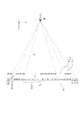
本開示の一実施形態にかかる3次元表示システム1は、図1に示されるように、検出装置2と、3次元表示装置3とを含んで構成される。
As illustrated in FIG. 1, the three-
以下に、3次元表示システム1の構成について詳細に説明する。図1の検出装置2は、利用者の左眼および右眼のいずれか一方の位置を検出し、コントローラ7に出力する。検出装置2は、例えば、カメラを備えてよい。検出装置2は、カメラによって利用者の顔を撮影してよい。検出装置2は、カメラの撮影画像から左眼および右眼の少なくとも一方の位置を検出してよい。検出装置2は、1個のカメラの撮影画像から、左眼および右眼の少なくとも一方の位置を3次元空間の座標として検出してよい。検出装置2は、2個以上のカメラの撮影画像から、左眼および右眼の少なくとも一方の位置を3次元空間の座標として検出してよい。
Hereinafter, the configuration of the three-
検出装置2は、カメラを備えず、装置外のカメラに接続されていてよい。検出装置2は、装置外のカメラからの信号を入力する入力端子を備えてよい。装置外のカメラは、入力端子に直接的に接続されてよい。装置外のカメラは、共有のネットワークを介して入力端子に間接的に接続されてよい。カメラを備えない検出装置2は、カメラが映像信号を入力する入力端子を備えてよい。カメラを備えない検出装置2は、入力端子に入力された映像信号から左眼および右眼の少なくとも一方の位置を検出してよい。
The
検出装置2は、例えば、センサを備えてよい。センサは、超音波センサまたは光センサ等であってよい。検出装置2は、センサによって利用者の頭部の位置を検出し、頭部の位置に基づいて左眼および右眼の少なくとも一方の位置を検出してよい。検出装置2は、1個または2個以上のセンサによって、左眼および右眼の少なくとも一方の位置を3次元空間の座標として検出してよい。
The
3次元表示システム1は、検出装置2を備えなくてよい。3次元表示システム1が検出装置2を備えない場合、コントローラ7は、装置外の検出装置からの信号を入力する入力端子を備えてよい。装置外の検出装置は、入力端子に接続されてよい。装置外の検出装置は、入力端子に対する伝送信号として、電気信号および光信号を用いてよい。装置外の検出装置は、共有のネットワークを介して入力端子に間接的に接続されてよい。コントローラ7は、装置外の検出装置から取得した左眼および右眼の少なくとも一方の位置を示す位置座標が入力されてもよい。また、コントローラ7は、位置座標に基づいて、水平方向に沿った、左眼および右眼の移動距離を算出してよい。
The three-
図1に示したように、3次元表示装置3は、照射器4、表示パネル5、光学素子としてのパララックスバリア6、コントローラ7を含んで構成される。
As shown in FIG. 1, the three-
照射器4は、表示パネル5を面的に照射する。照射器4は、光源、導光板、拡散板、拡散シート等を含んで構成されてよい。照射器4は、光源により照射光を射出し、導光板、拡散板、拡散シート等により照射光を表示パネル5の面方向に均一化する。そして、照射器4は均一化された光を表示パネル5の方に出射する。
The
表示パネル5の表示面51は、第1方向(x軸方向)に沿う方向に曲率が無く、図1に示したように、第1方向に直交する面(yz平面)内で曲率を有する曲面である。利用者の眼の基準位置PSから表示面51に下ろした垂線の表示面51との交点を中心点とし、該中心点における表示面51上で第1方向に直交する方向が、第2方向(y軸方向)とされる。第1および第2方向に直交する、表示面51の中心点と基準位置PSとを結ぶ方向が、第3方向(z軸方向)とされる。以下の実施形態で、第1方向は水平方向、第2方向は鉛直方向、第3方向は奥行方向と称されるが、第1方向、第2方向および第3方向はこれらに限られない。以下の実施形態では、表示パネル5の中心点と、鉛直方向において同一の位置を鉛直方向標準位置Oyという。鉛直方向標準位置Oyは、表示面51の鉛直方向での中心である。また、鉛直方向標準位置Oyは、パララックスバリア6の鉛直方向での中心に対向する、表示面51上の位置であってよい。
The
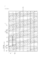
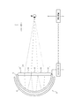
さらに、図2に示すように、表示面51の曲面内において、第1方向に対応する方向を第1面内方向(u軸方向)、第1方向に沿う方向に直交する方向を第2面内方向(v軸方向)とする。第1方向および第1面内方向は、観察時における利用者の両眼の眼球中心を結ぶ方向に対応する方向となる。
Further, as shown in FIG. 2, in the curved surface of the
表示パネル5は、第1面内方向および第2面内方向に沿って格子状に配列された複数のサブピクセルを含む表示面51を有する。図2においては、説明の便宜上、紙面により構成される平面内に表示パネル5が示されているが、実際には表示パネル5は、利用者側に対する面が凹んだ曲面を有し、yz平面内に、例えば円弧を形成するように湾曲している。
The
区画領域の各々には、1つのサブピクセルが対応する。複数のサブピクセルは、第1面内方向および第2面内方向にマトリクス状に配列されている。各サブピクセルはR,G,Bの各色に対応し、R,G,Bの3つのサブピクセルを一組として1ピクセルを構成することができる。1ピクセルは、1画素と称されることがある。表示パネル5は、透過型の液晶パネルに限られず、有機EL等他の表示パネルであってよい。表示パネル5が自発光型の表示パネルである場合、照射器4は不要である。
Each sub-region corresponds to one subpixel. The plurality of subpixels are arranged in a matrix in the first in-plane direction and the second in-plane direction. Each subpixel corresponds to each color of R, G, and B, and one pixel can be formed by combining three subpixels of R, G, and B as a set. One pixel may be referred to as one pixel. The
パララックスバリア6は、サブピクセルから射出される画像光の光線方向を規定する。図1に示したように、パララックスバリア6は、表示面51に沿う曲面により形成され、表示面51から所定距離、離れて配置される。パララックスバリア6は、図2に示したように、曲面内の所定方向に伸びる複数の帯状領域である開口領域62ごとに、サブピクセルから射出される画像光の伝播方向である光線方向を規定する。所定方向は、第2面内方向に対して、0度でない所定の角度を有する方向である。パララックスバリア6がサブピクセルから射出される画像光を規定することによって、利用者の眼が視認可能な表示面51の範囲、すなわち可視領域51aが定まる。パララックスバリア6は、図1に示したように、表示パネル5に対して照射器4の反対側に位置する。パララックスバリア6は、表示パネル5の照射器4側に位置してよい。
The
具体的には、パララックスバリア6は、図2に示したように、複数の、画像光を遮光する遮光面61を有する。複数の遮光面61は、互いに隣接する該遮光面61の間の開口領域62を画定する。開口領域62は、遮光面61に比べて光透過率が高い。遮光面61は、開口領域62に比べて光透過率が低い。
Specifically, as illustrated in FIG. 2, the
開口領域62は、パララックスバリア6に入射する光を透過させる部分である。開口領域62は、第1所定値以上の透過率で光を透過させてよい。第1所定値は、例えば100%であってよいし、100%に近い値であってよい。遮光面61は、パララックスバリア6に入射する光を遮って透過させない部分である。言い換えれば、遮光面61は、3次元表示装置3に表示される画像を遮る。遮光面61は、第2所定値以下の透過率で光を遮ってよい。第2所定値は、例えば0%であってよいし、0%に近い値であってよい。
The
開口領域62と遮光面61とは、表示面51に沿う面内の所定方向に延び、所定方向と直交する方向に繰り返し交互に配列される。開口領域62は、サブピクセルから射出される画像光の光線方向を規定する。
The
仮に、開口領域62の端部を示す線が第2面内方向に延びる場合、パララックスバリア6の開口のパターンと、表示パネル5が表示する画素パターンとの間にモアレが発生する場合がある。開口領域62の端部を示す線が第2面内方向に対して0度でない所定の角度を有する所定方向に延びる場合、表示画像においてモアレの発生が低減される。
If the line indicating the end of the
パララックスバリア6は、第2所定値未満の透過率を有するフィルムまたは板状部材で構成されてよい。この場合、遮光面61は、当該フィルムまたは板状部材で構成される。開口領域62は、フィルムまたは板状部材に設けられた開口で構成される。フィルムは、樹脂で構成されてよいし、他の材料で構成されてよい。板状部材は、樹脂または金属等で構成されてよいし、他の材料で構成されてよい。パララックスバリア6は、フィルムまたは板状部材に限られず、他の種類の部材で構成されてよい。パララックスバリア6は、基材が遮光性を有してよいし、基材に遮光性を有する添加物が含有されてよい。
The
パララックスバリア6は、液晶シャッターで構成されてよい。液晶シャッターは、印加する電圧に応じて光の透過率を制御しうる。液晶シャッターは、複数の画素で構成され、各画素における光の透過率を制御してよい。液晶シャッターは、光の透過率が高い領域または光の透過率が低い領域を任意の形状に形成してうる。パララックスバリア6が液晶シャッターで構成される場合、開口領域62は、第1所定値以上の透過率を有する領域としてよい。パララックスバリア6が液晶シャッターで構成される場合、遮光面61は、第2所定値以下の透過率を有する領域としてよい。
The
このように構成されることによって、パララックスバリア6は、表示面51の一部のサブピクセルから出射した画像光を、開口領域62を通過させ利用者の右眼に伝搬させる。パララックスバリア6は、他の一部のサブピクセルから出射した画像光を、開口領域62を通過させ利用者の左眼に伝搬させる。
With this configuration, the
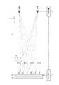
具体的には、図3に示すように、パララックスバリア6の開口領域62を透過した画像光が利用者の左眼に到達することによって、利用者の左眼は、開口領域62に対応する可視領域51aを視認しうる。パララックスバリア6の遮光面61によって画像光が遮られることによって、利用者の左眼は、遮光面61に対応する不可視領域51bを視認できない。したがって、可視領域51aのサブピクセルに左眼画像が表示され、不可視領域51bのサブピクセルに右眼画像が表示されると、左眼は左眼画像のみを視認する。
Specifically, as shown in FIG. 3, when the image light transmitted through the
また、パララックスバリア6の開口領域62を透過した他の一部のサブピクセルからの画像光が利用者の右眼に到達することによって、利用者の右眼は、左眼には視認することのできない不可視領域51bを視認しうる。パララックスバリア6の遮光面61によって画像光が遮られることによって、利用者の右眼は、左眼が視認することのできる可視領域51aを視認できない。そのため、上述のように、可視領域51aのサブピクセルに左眼画像が表示され、不可視領域51bのサブピクセルに右眼画像が表示されると、右眼は右眼画像のみを視認する。すなわち、左眼は左眼画像のみを視認し、右眼は右眼画像のみを視認するため、利用者は、視差のある画像、すなわち立体的な画像を認識することになる。
Further, when the image light from some other sub-pixels transmitted through the
コントローラ7は、3次元表示システム1の各構成要素に接続され、各構成要素を制御する。コントローラ7によって制御される構成要素は、検出装置2および表示パネル5を含む。コントローラ7は、例えばプロセッサとして構成される。コントローラ7は、1以上のプロセッサを含んでよい。プロセッサは、特定のプログラムを読み込ませて特定の機能を実行する汎用のプロセッサ、および特定の処理に特化した専用のプロセッサを含んでよい。専用のプロセッサは、特定用途向けIC(ASIC:Application Specific Integrated Circuit)を含んでよい。プロセッサは、プログラマブルロジックデバイス(PLD:Programmable Logic Device)を含んでよい。PLDは、FPGA(Field-Programmable Gate Array)を含んでよい。コントローラ7は、1つまたは複数のプロセッサが協働するSoC(System-on-a-Chip)、およびSiP(System In a Package)のいずれかであってよい。コントローラ7は、記憶部を備え、記憶部に各種情報、または3次元表示システム1の各構成要素を動作させるためのプログラム等を格納してよい。記憶部は、例えば半導体メモリ等で構成されてよい。記憶部は、コントローラ7のワークメモリとして機能してよい。
The
コントローラ7は、検出装置2によって検出された利用者の眼の位置を取得する。また、コントローラ7は、利用者の眼の位置に応じて、サブピクセルに表示させる画像を変更する。具体的には、コントローラ7は、サブピクセルに表示される画像を右眼画像と左眼画像との間で切り替えを行う。ここで、コントローラ7がサブピクセルに表示されている画像を変更する方法を説明するために、まず、表示パネル5およびパララックスバリア6について詳細に説明する。
The
以下では、まず、表示パネル5とパララックスバリア6とを平面に展開した図2を用いて説明し、次に表示パネル5とパララックスバリア6とが曲面である場合を説明する。
Hereinafter, the
図2に示したように、表示パネル5の表示面51に表示されるサブピクセルの第1面内方向の長さをHp、第2面内方向の長さをVpとする。この場合、開口領域62を透過して左眼で視認することができる画像上の領域である可視領域51aの端部が形成する直線の傾きの絶対値は、自然数aおよびbを用いてb×Vp/(a×Hp)と表される。図2に示す例では、a=1、b=1である。すなわち、表示面51の開口領域62を画定する2つの直線の、第1面内方向に対する傾きは1×Vp/(1×Hp)である。
As shown in FIG. 2, the length in the first in-plane direction of the sub-pixel displayed on the
また、表示面51には、第1面内方向にn個、第2面内方向にb個、連続して配列された(n×b)個(以降において、n×b=mとする)のサブピクセルを含む第1のサブピクセル群Pglに左眼画像が表示される。図2に示す例では、表示面51には、第1面内方向に4個、第2面内方向に1個、連続して左眼画像が表示されている。また、表示面51には、第1のサブピクセル群Pglの第2面内方向に隣接し、且つ、第1面内方向に1サブピクセル分ずれた位置に、同様に配列された第1のサブピクセル群Pglが配置され、左眼画像が表示される。
In addition, the
さらに、表示面51には、第1のサブピクセル群Pglに第1面内方向に隣接する、第1面内方向にn個、第2面内方向にb個、連続して配列されたm個のサブピクセルを含む第2のサブピクセル群Pgrに右眼画像が表示される。図2に示す例では、表示面51には、第1のサブピクセル群Pglに第1面内方向に隣接して、第1面内方向に4個、第2面内方向に1個、連続して右眼画像が表示されている。
Further, on the
このように、第1面内方向にn個連続して左目画像が表示され、左目画像に隣接して第1面内方向にn個連続して右眼画像が表示されるため、第1面内方向の画像の配置間隔である画像ピッチkは、2n×Hpと表される。図2に示す例では、画像ピッチkは、2×4×Hp=8×Hpと表される。 In this way, the left eye image is displayed in succession in the first in-plane direction, and the right eye image is displayed in succession in the first in-plane direction adjacent to the left eye image. The image pitch k, which is the arrangement interval of the images in the inward direction, is expressed as 2n × Hp. In the example shown in FIG. 2, the image pitch k is expressed as 2 × 4 × Hp = 8 × Hp.
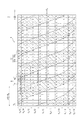
このような表示面51及びパララックスバリア6は、基準位置PSにある利用者の眼には、図4に示すように見える。表示面51は、鉛直方向標準位置Oyから鉛直方向に離れるに従い、奥行方向の利用者の眼側に傾く。そのため、基準位置PSにある利用者の眼から見ると、サブピクセルが鉛直方向標準位置Oyから鉛直方向に離れる位置にあるほど、該サブピクセルの鉛直方向の成分が縮小して見える。言い換えれば、表示パネル5のサブピクセルの鉛直方向の成分は、鉛直方向標準位置Oyから鉛直方向に離れるほど、短くなる。
図4に示す例では、利用者の眼から見えるサブピクセルの鉛直方向の長さをVp(k)(kは0でない整数)とすると、Vp(1)>Vp(2)>Vp(3)>・・・となる。また、Vp(−1)>Vp(−2)>Vp(−3)>・・・となる。 In the example shown in FIG. 4, assuming that the vertical length of the sub-pixels visible to the user's eyes is Vp (k) (k is an integer other than 0), Vp (1)> Vp (2)> Vp (3) > ... Further, Vp (-1)> Vp (-2)> Vp (-3)>.
また、表示面51に沿ってパララックスバリア6が配置されている。このため、図4に示す例では、基準位置Psでの左眼の可視領域51aは、サブピクセルP12〜P14、P22〜P24、P32〜P34、P42〜P44、及びP52〜P54の全部を含む。さらに、基準位置Psでの左眼の可視領域51aは、P11、P15、P21、P25、P31、P35、P41、及びP45の一部を含む。このとき、コントローラ7は、サブピクセルP11〜P14、P21〜P24、P31〜P34、P41〜P44、P51〜P54に左眼画像を表示する。また、コントローラ7は、サブピクセルP15〜P18、P25〜P28、P35〜P38、P45〜P48、P55〜P58に右眼画像を表示する。このため、利用者の左眼が視認する画像の大部分は左眼画像となる。同様にして、右眼が視認する画像の大部分は右眼画像となる。このため、クロストークの発生は最小となっている。図4に示す例では、パララックスバリア6の開口率は50%であるが、光量及びクロストークのバランスを鑑み、開口率を適宜設計することができる。例えば、パララックスバリア6の開口率を例えば、25%とした場合、クロストークを全く発生しないようにすることができる。
A
ここで、コントローラ7が、検出装置2によって検出された眼の、鉛直方向の変位に基づいて、各サブピクセルに表示される画像を変更する方法について説明する。以降の説明においては、コントローラ7が左眼の基準位置Psからの変位に基づいて画像を変更する方法について説明する。コントローラ7が右眼の基準位置Psからの変位に基づいて画像を変更する方法も同様である。
Here, a method in which the
図5に示すように、利用者の眼が基準位置Psから鉛直方向に変位した場合、図6に示されるように、変位位置での左眼の可視領域51aは、図4に示した基準位置Psでの左眼の可視領域51aとは異なる。具体的には、変位位置での可視領域51aに含まれるサブピクセルP15、P25、P35の部分は、それぞれ基準位置Psでの可視領域51aに含まれるサブピクセルP15、P25、P35の部分より大きい。また、基準位置Psでは可視領域51aに含まれなかったサブピクセルP16、P26、P36の一部が、変位位置での可視領域51aに含まれる。そのため、変位位置においては、利用者の左眼には、右眼画像を表示しているサブピクセルP15、P25、P35の大部分、およびサブピクセルP16、P26、P36の一部が左眼の可視領域51aに含まれるようになるため、左眼に発生するクロストークが増加している。
As shown in FIG. 5, reference the user's eyes may displaced in the vertical direction from the reference position P s, as shown in FIG. 6, the
そこで、コントローラ7は、利用者の眼が鉛直方向に変位すると、例えば、左眼の可視領域51aに半分より大きい部分が含まれるサブピクセルP15,P25,P35に表示させる画像を変更し、右眼画像ではなく左眼画像を表示させる。このとき、可視領域51aに含まれるサブピクセルP16、P26、P36の部分は、それぞれサブピクセルP16、P26、P36の半分に満たない。このため、コントローラ7は、サブピクセルP16、P26、P36に表示させる画像を変更させず、引き続き、右眼画像を表示させる。
Therefore, when the user's eyes are displaced in the vertical direction, the
このとき、コントローラ7は、可視領域51aに含まれる部分が少なくなった、すなわち右眼に大部分が視認されるようになったサブピクセルP11、P21、P31に表示させる画像を変更し、左眼画像ではなく右眼画像を表示させる。
At this time, the
鉛直方向標準位置Oyからさらに離れた位置においては、眼が基準位置Psにあるときに可視領域51aにサブピクセルP45、P55の一部が含まれていたが、眼が変位位置にあるときサブピクセルP45、P55の全部が可視領域51aに含まれる。そこで、コントローラ7は、サブピクセルP45、P55に表示させる画像を変更し、右眼画像ではなく左眼画像を表示させる。さらに、眼が基準位置にあるときに可視領域51aにサブピクセルP46、P56は含まれていなかったが、眼が変位位置にあるときサブピクセルP46、P56の半分以上が可視領域51aに含まれる。そこで、コントローラ7は、サブピクセルP46、P56に表示させる画像も変更し、右眼画像ではなく左眼画像を表示させる。
In a further away from the vertical standard position O y, but the eyes had some of the sub-pixels P45, P55 in the
また、コントローラ7は、可視領域51aに含まれなくなった、すなわち右眼に視認されるようになったサブピクセルP41、P51に表示させる画像を変更し、左眼画像ではなく右眼画像を表示させる。さらに、コントローラ7は、可視領域51aに含まれる部分が少なくなった、すなわち右眼に大部分が視認されるようになったサブピクセルP42、P52に表示させる画像も変更し、左眼画像ではなく右眼画像を表示させる。
Further, the
このように、コントローラ7は、鉛直方向標準位置Oyからの距離に基づいてサブピクセルに表示する画像を変更する。具体的には、コントローラ7は、利用者が、眼が基準位置Psから鉛直方向に変位すると、各水平方向に配列されたサブピクセル群のうち鉛直方向の眼の変位量に応じた数のサブピクセルに表示される画像を、右眼画像と左眼画像との間で切り替える。切り替えが必要となるサブピクセルの数は、表示面51の鉛直方向標準位置Oyの近くに位置するサブピクセルよりも、表示面51の鉛直方向標準位置Oyから離れて位置するサブピクセルの方が多い。言い換えれば、コントローラ7は、鉛直方向標準位置Oyから鉛直方向に離れて位置するサブピクセル群ほど、より狭い間隔での眼の変位に対して画像を切り替える必要がある。このように、コントローラ7がサブピクセルに表示させる画像を制御することによって、曲面状の表示面51を有する3次元表示装置3においてもクロストークが低減される。
Thus, the
続いて、コントローラ7が、検出装置2によって検出された眼の、奥行方向であって、表示面51へ近づく方向への変位に基づいてサブピクセルに表示する画像を変更する方法について説明する。
Next, a method in which the
まず、表示面51が曲面ではなく、平面である場合の適視距離dyについて、図7を参照して説明する。適視距離dyは、鉛直方向の画像の配列に起因するクロストークが最も少なくなるような、表示面51と利用者の眼との間の距離である。適視距離dyは、鉛直方向のバリアピッチBpy、鉛直方向の画像ピッチky、表示面51とパララックスバリア6との距離gを用いて、次の式(1)で規定される。
dy:Bpy=(dy+g):ky 式(1)
First, the
d y: Bp y = (d y + g): k y formula (1)
本実施形態では、上述のように、表示パネル5は、yz平面内に、例えば円弧を形成するような曲面により構成されている。表示パネル5は、曲面内において、第1面内方向および第2面内方向にそれぞれ等間隔に区画された複数の区画領域にそれぞれ配置されるサブピクセルを有する。
In the present embodiment, as described above, the
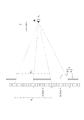
したがって、図8に示すように、利用者の眼が基準位置Psにある場合、利用者の眼から鉛直方向標準位置Oyまでの観察距離が適視距離dyである場合、利用者の左眼の可視領域51a(1)及び51a(2)のサブピクセルには左眼画像が表示される。すなわち、利用者の左眼は左眼画像を視認する。同様にして、利用者の右眼は右眼画像を視認する。これにより、利用者はクロストークが低減された状態で立体画像を認識する。
Accordingly, as shown in FIG. 8, the user when the eye is in the reference position P s, when the viewing distance from the user's eyes to the vertical standard position O y is proper viewing distance d y, the user The left eye image is displayed in the sub-pixels of the left eye
この状態で、図9に示すように、観察距離が適視距離dyより短くなった場合、鉛直方向標準位置Oyから最も近い可視領域51a(1)には左眼画像を表示する4つのサブピクセルと右眼画像を表示する1つのサブピクセルの一部とが含まれる。可視領域51a(1)に含まれる右眼画像の部分は右眼画像全体の半分以下である場合、コントローラ7は、当該右眼画像を表示するサブピクセルに引き続き右眼画像を表示する。すなわち、コントローラ7はサブピクセルに表示する画像を変更しない。また、可視領域51a(1)に含まれる右眼画像の部分は右眼画像全体の半分以上である場合、コントローラ7は、当該右眼画像を表示する1つのサブピクセルに左眼画像を表示するよう変更する。
In this state, as shown in FIG. 9, if the viewing distance is shorter than the proper viewing distance d y, four of displaying left-eye image to the closest
また、利用者の眼が奥行方向の変位位置にある場合、鉛直方向標準位置Oyから遠い位置にある可視領域51a(2)には2つの左眼画像と4つの右眼画像とをそれぞれ表示するサブピクセルが含まれる。このため、鉛直方向標準位置Oyから離れた可視領域51a(2)からの画像光により利用者の眼に発生するクロストークは、可視領域51a(1)からのからの画像光からの画像光により利用者の眼に発生するクロストークに比べて増加している。そこで、コントローラ7は、可視領域51a(2)に含まれる右眼画像を表示していた4つのサブピクセルに左眼画像を表示するよう変更する。また、コントローラ7は、可視領域51aに含まれなくなった、すなわち右眼に視認されるようになったサブピクセルに表示されていた左眼画像を右眼画像に変更する。これにより、左眼に視認される右眼画像が減少し、右眼画像に視認される左眼画像が減少する。したがって、利用者の眼に発生するクロストークが減少する。
The display case of the user's eyes are in the displaced position in the depth direction, 4 and two left-eye image one is in the
このように、コントローラ7は、眼が基準位置Psから奥行方向の、表示面51に近づく方向に変位すると、鉛直方向標準位置Oyの近くに位置する可視領域51a(1)の0または1つのサブピクセルに表示する画像を変更する。これに対し、コントローラ7は、鉛直方向標準位置Oyから離れて位置する可視領域51a(2)の4つのサブピクセルに表示する画像を変更する。すなわち、コントローラ7は、鉛直方向に配列されたサブピクセルのうち、奥行方向の眼の変位量に応じた数のサブピクセルに表示される画像を、右眼画像と左眼画像との間で切り替える。切り替えが必要となるサブピクセルの数は、表示面51において鉛直方向標準位置Oyの近くに位置するサブピクセルよりも、鉛直方向標準位置Oyから離れて位置するサブピクセルの方が多い。言い換えれば、コントローラ7は、鉛直方向標準位置Oyから鉛直方向に離れて位置するサブピクセル群ほど、より狭い間隔での奥行方向の眼の変位に対して画像を切り替える必要がある。このように、コントローラ7がサブピクセルに表示させる画像を制御することによって、曲面状の表示面51を有する3次元表示装置3においてもクロストークが低減される。
Thus, the
上述において、眼が表示面51に近づく方向へ変位した場合の画像の変更について説明したが、眼が表示面51から離れる方向へ変位する場合の画像の変更も同様である。すなわち、コントローラ7によって切り替えが必要となるサブピクセルの数は、表示面51において鉛直方向標準位置Oyの近くに位置するサブピクセルよりも、鉛直方向標準位置Oyから離れて位置するサブピクセルの方が多い。したがって、同様にして、コントローラ7は、鉛直方向標準位置Oyから鉛直方向に離れて位置するサブピクセル群ほど、より狭い間隔の奥行方向の変位に対して画像を切り替える必要がある。
In the above description, the image change when the eye is displaced in the direction approaching the
上述の実施形態は代表的な例として説明したが、本発明の趣旨および範囲内で、多くの変更および置換ができることは当業者に明らかである。したがって、本発明は、上述の実施形態によって制限するものと解するべきではなく、特許請求の範囲から逸脱することなく、種々の変形や変更が可能である。例えば、実施形態および実施例に記載の複数の構成ブロックを1つに組合せたり、あるいは1つの構成ブロックを分割したりすることが可能である。 While the above embodiments have been described as representative examples, it will be apparent to those skilled in the art that many changes and substitutions can be made within the spirit and scope of the invention. Therefore, the present invention should not be construed as being limited by the above-described embodiments, and various modifications and changes can be made without departing from the scope of the claims. For example, a plurality of constituent blocks described in the embodiments and examples can be combined into one, or one constituent block can be divided.
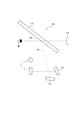
上述の各実施形態では、光学素子がパララックスバリア6であるとしたが、これに限られない。例えば、3次元表示装置3が備える光学素子は、レンチキュラレンズ9としてもよい。この場合、レンチキュラレンズ9は、図10に示すように、シリンドリカルレンズ10を、xy平面内に配列して構成される。レンチキュラレンズ9は、パララックスバリア6と同様に、可視領域51aのサブピクセルを出射した画像光を、利用者の左眼の位置に伝搬させ、他の一部の可視領域51aのサブピクセルを出射した画像光を、利用者の右眼の位置に伝搬させる。
In each of the embodiments described above, the optical element is the
また、図11に示されるように、3次元表示システム1は、ヘッドアップディスプレイ100に搭載されうる。ヘッドアップディスプレイ100は、HUD(Head Up Display)100ともいう。HUD100は、3次元表示システム1と、光学部材110と、被投影面130を有する被投影部材120とを備える。HUD100は、3次元表示システム1から射出される画像光を、光学部材110を介して被投影部材120に到達させる。HUD100は、被投影部材120で反射させた画像光を、利用者の左眼および右眼に到達させる。つまり、HUD100は、破線で示される光路140に沿って、3次元表示システム1から利用者の左眼および右眼まで画像光を進行させる。利用者は、光路140に沿って到達した画像光を、虚像150として視認しうる。3次元表示システム1は、利用者の左眼および右眼の位置に応じて表示を制御することによって、利用者の動きに応じて立体視を提供しうる。
As shown in FIG. 11, the three-
また、図12に示されるように、HUD100および3次元表示システム1は、移動体に搭載されてよい。HUD100および3次元表示システム1は、構成の一部を、当該移動体が備える他の装置、部品と兼用してよい。例えば、移動体は、ウインドシールドを被投影部材120として兼用してよい。構成の一部を当該移動体が備える他の装置、部品と兼用する場合、他の構成をHUDモジュールまたは3次元表示コンポーネントと呼びうる。3次元表示システム1および3次元表示装置3は、移動体に搭載されてよい。本開示における「移動体」には、車両、船舶、航空機を含む。本開示における「車両」には、自動車および産業車両を含むが、これに限られず、鉄道車両および生活車両、滑走路を走行する固定翼機を含めてよい。自動車は、乗用車、トラック、バス、二輪車、およびトロリーバス等を含むがこれに限られず、道路上を走行する他の車両を含んでよい。産業車両は、農業および建設向けの産業車両を含む。産業車両には、フォークリフト、およびゴルフカートを含むがこれに限られない。農業向けの産業車両には、トラクター、耕耘機、移植機、バインダー、コンバイン、および芝刈り機を含むが、これに限られない。建設向けの産業車両には、ブルドーザー、スクレーバー、ショベルカー、クレーン車、ダンプカー、およびロードローラを含むが、これに限られない。車両は、人力で走行するものを含む。なお、車両の分類は、上述に限られない。例えば、自動車には、道路を走行可能な産業車両を含んでよく、複数の分類に同じ車両が含まれてよい。本開示における船舶には、マリンジェット、ボート、タンカーを含む。本開示における航空機には、固定翼機、回転翼機を含む。
Moreover, as FIG. 12 shows, HUD100 and the three-
1 3次元表示システム
2 検出装置
3 3次元表示装置
4 照射器
5 表示パネル
6 パララックスバリア
7 コントローラ
8 移動体
9 レンチキュラレンズ
10 シリンドリカルレンズ
51 表示面
51a 可視領域
51b 不可視領域
60 パララックスバリア
61 遮光面
62 開口領域
100 ヘッドアップディスプレイシステム
110 光学部材
120 被投影部材
130 被投影面
140 光路
150 虚像
DESCRIPTION OF
Claims (8)
前記曲面に沿って配置され、前記曲面に沿った面内の所定方向に延びる複数の帯状領域ごとに、前記サブピクセルから射出される画像光の光線方向を規定する光学素子と、
利用者の眼の位置を取得し、前記表示面、前記光学素子、および前記利用者の眼の位置に基づいて前記複数のサブピクセルにそれぞれ表示する画像を変更するコントローラと、
を備える3次元表示装置。 A display surface having a curvature in a plane orthogonal to the first direction and having no curvature in the direction along the first direction, the display surface being orthogonal to the first direction and the first direction A display surface including a plurality of subpixels arranged in a grid along the direction of
An optical element that is arranged along the curved surface and defines a light beam direction of image light emitted from the sub-pixel for each of a plurality of strip-like regions extending in a predetermined direction in the surface along the curved surface;
A controller that acquires a position of a user's eye and changes an image to be displayed on each of the plurality of sub-pixels based on the display surface, the optical element, and the position of the user's eye;
A three-dimensional display device comprising:
第1方向に沿う方向に曲率がなく、第1方向に直交する面内で曲率を有する曲面から構成される表示面であって、前記第1方向と前記第1方向に直交する前記表示面内の方向に沿って格子状に配列された複数のサブピクセルを有する表示面と、
前記曲面に沿って配置され、前記曲面に沿った面内の所定方向に延びる複数の帯状領域ごとに、前記サブピクセルから射出される画像光の光線方向を規定する光学素子と、
前記利用者の眼の位置を取得し、前記表示面、前記光学素子、および前記利用者の眼の位置に基づいて前記複数のサブピクセルにそれぞれ表示する画像を変更するコントローラと、を含む3次元表示装置と、
を備える3次元表示システム。 A detection device for detecting the position of the user's eyes;
A display surface having a curvature in a plane orthogonal to the first direction and having no curvature in the direction along the first direction, the display surface being orthogonal to the first direction and the first direction A display surface having a plurality of subpixels arranged in a grid pattern along the direction of
An optical element that is arranged along the curved surface and defines a light beam direction of image light emitted from the sub-pixel for each of a plurality of strip-like regions extending in a predetermined direction in the surface along the curved surface;
A controller that obtains the position of the user's eye and changes the image to be displayed on each of the plurality of sub-pixels based on the display surface, the optical element, and the position of the user's eye. A display device;
A three-dimensional display system.
を備えるヘッドアップディスプレイシステム。 A display surface having a curvature in a plane orthogonal to the first direction and having no curvature in the direction along the first direction, the display surface being orthogonal to the first direction and the first direction A display surface having a plurality of sub-pixels arranged in a lattice shape along the direction of the plurality of strip-shaped regions arranged along the curved surface and extending in a predetermined direction within the surface along the curved surface. An optical element that defines a light beam direction of image light emitted from a pixel; and a position of the user's eye; and a plurality of the plurality of light sources based on the display surface, the optical element, and the position of the user's eye A head-up display system comprising a three-dimensional display device including a controller that changes an image displayed on each subpixel.
第1方向に沿う方向に曲率がなく、第1方向に直交する面内で曲率を有する曲面から構成される表示面であって、前記第1方向と前記第1方向に直交する前記表示面内の方向に沿って格子状に配列された複数のサブピクセルを備える表示面と、前記曲面に沿って配置され、前記曲面に沿った面内の所定方向に延びる複数の帯状領域ごとに、前記サブピクセルから射出される画像光の光線方向を規定する光学素子と、前記利用者の眼の位置を取得し、前記表示面、前記光学素子、および前記利用者の眼の位置に基づいて前記複数のサブピクセルにそれぞれ表示する画像を変更するコントローラと、を有する3次元表示装置と、
を含む3次元表示システムを備える移動体。 A detection device for detecting the position of the user's eyes;
A display surface having a curvature in a plane orthogonal to the first direction and having no curvature in the direction along the first direction, the display surface being orthogonal to the first direction and the first direction A display surface including a plurality of subpixels arranged in a grid pattern along the direction of the display, and a plurality of strip regions arranged along the curved surface and extending in a predetermined direction along the curved surface. An optical element that defines a light beam direction of image light emitted from a pixel; and a position of the user's eye; and a plurality of the plurality of light sources based on the display surface, the optical element, and the position of the user's eye A three-dimensional display device having a controller for changing an image to be displayed on each subpixel;
A moving object comprising a three-dimensional display system including:
Priority Applications (4)
| Application Number | Priority Date | Filing Date | Title |
|---|---|---|---|
| JP2017087699A JP2018185437A (en) | 2017-04-26 | 2017-04-26 | Three-dimensional display unit, three-dimensional display system, head-up display system, and movable body |
| EP18791699.4A EP3617774A1 (en) | 2017-04-26 | 2018-04-25 | Three-dimensional display device, three-dimensional display system, head-up display system, and mobile body |
| PCT/JP2018/016860 WO2018199183A1 (en) | 2017-04-26 | 2018-04-25 | Three-dimensional display device, three-dimensional display system, head-up display system, and mobile body |
| US16/660,404 US20200053352A1 (en) | 2017-04-26 | 2019-10-22 | Three-dimensional display apparatus, three-dimensional display system, head-up display system, and mobile body |
Applications Claiming Priority (1)
| Application Number | Priority Date | Filing Date | Title |
|---|---|---|---|
| JP2017087699A JP2018185437A (en) | 2017-04-26 | 2017-04-26 | Three-dimensional display unit, three-dimensional display system, head-up display system, and movable body |
Publications (1)
| Publication Number | Publication Date |
|---|---|
| JP2018185437A true JP2018185437A (en) | 2018-11-22 |
Family
ID=63919718
Family Applications (1)
| Application Number | Title | Priority Date | Filing Date |
|---|---|---|---|
| JP2017087699A Withdrawn JP2018185437A (en) | 2017-04-26 | 2017-04-26 | Three-dimensional display unit, three-dimensional display system, head-up display system, and movable body |
Country Status (4)
| Country | Link |
|---|---|
| US (1) | US20200053352A1 (en) |
| EP (1) | EP3617774A1 (en) |
| JP (1) | JP2018185437A (en) |
| WO (1) | WO2018199183A1 (en) |
Cited By (2)
| Publication number | Priority date | Publication date | Assignee | Title |
|---|---|---|---|---|
| JP2022533657A (en) * | 2019-05-17 | 2022-07-25 | フューチュラス テクノロジー カンパニー リミテッド | Head-up display systems, active emissive image sources, head-up displays and automobiles |
| WO2023100956A1 (en) * | 2021-11-30 | 2023-06-08 | 京セラ株式会社 | Three-dimensional display device, three-dimensional display system, and mobile object |
Families Citing this family (3)
| Publication number | Priority date | Publication date | Assignee | Title |
|---|---|---|---|---|
| JP7141975B2 (en) * | 2019-03-26 | 2022-09-26 | 京セラ株式会社 | Image display module, image display system, moving body, image display method, and image display program |
| CN112752085A (en) * | 2020-12-29 | 2021-05-04 | 北京邮电大学 | Naked eye 3D video playing system and method based on human eye tracking |
| CN113031300A (en) * | 2021-03-11 | 2021-06-25 | 合肥鑫晟光电科技有限公司 | Display device and control method thereof |
Family Cites Families (11)
| Publication number | Priority date | Publication date | Assignee | Title |
|---|---|---|---|---|
| JPH10174127A (en) * | 1996-12-13 | 1998-06-26 | Sanyo Electric Co Ltd | Method and device for three-dimensional display |
| JP3668116B2 (en) | 1999-09-24 | 2005-07-06 | 三洋電機株式会社 | 3D image display device without glasses |
| JP3966830B2 (en) * | 2003-03-28 | 2007-08-29 | 株式会社東芝 | 3D display device |
| JP2007256964A (en) * | 2007-04-23 | 2007-10-04 | Toshiba Corp | Stereoscopic image display device |
| DE102007026628B3 (en) * | 2007-06-07 | 2008-08-14 | Visumotion Gmbh | Parallax barrier screen adjusting method for industrial application, involves adjusting barrier screen to display screen such that adjustment of barrier screen to display screen with pixels is defined with preset tolerance of pixels |
| JP2012053345A (en) * | 2010-09-02 | 2012-03-15 | Sony Corp | Display apparatus |
| KR102111407B1 (en) * | 2013-08-19 | 2020-05-15 | 엘지전자 주식회사 | Display apparatus and method for operating the same |
| JP6076893B2 (en) * | 2013-12-27 | 2017-02-08 | 株式会社ジャパンディスプレイ | Display device and manufacturing method of display device |
| KR102030830B1 (en) * | 2014-07-18 | 2019-10-10 | 삼성전자주식회사 | Curved multiview image display apparatus and control method thereof |
| JP6411257B2 (en) * | 2015-03-19 | 2018-10-24 | 株式会社ジャパンディスプレイ | Display device and control method thereof |
| KR102415502B1 (en) * | 2015-08-07 | 2022-07-01 | 삼성전자주식회사 | Method and apparatus of light filed rendering for plurality of user |
-
2017
- 2017-04-26 JP JP2017087699A patent/JP2018185437A/en not_active Withdrawn
-
2018
- 2018-04-25 WO PCT/JP2018/016860 patent/WO2018199183A1/en unknown
- 2018-04-25 EP EP18791699.4A patent/EP3617774A1/en not_active Withdrawn
-
2019
- 2019-10-22 US US16/660,404 patent/US20200053352A1/en not_active Abandoned
Cited By (3)
| Publication number | Priority date | Publication date | Assignee | Title |
|---|---|---|---|---|
| JP2022533657A (en) * | 2019-05-17 | 2022-07-25 | フューチュラス テクノロジー カンパニー リミテッド | Head-up display systems, active emissive image sources, head-up displays and automobiles |
| JP7345209B2 (en) | 2019-05-17 | 2023-09-15 | フューチュラス テクノロジー カンパニー リミテッド | Head-up display systems, active emissive image sources, head-up displays and automobiles |
| WO2023100956A1 (en) * | 2021-11-30 | 2023-06-08 | 京セラ株式会社 | Three-dimensional display device, three-dimensional display system, and mobile object |
Also Published As
| Publication number | Publication date |
|---|---|
| WO2018199183A1 (en) | 2018-11-01 |
| EP3617774A1 (en) | 2020-03-04 |
| US20200053352A1 (en) | 2020-02-13 |
Similar Documents
| Publication | Publication Date | Title |
|---|---|---|
| WO2018139611A1 (en) | 3d display device, 3d display system, head-up display, head-up display system, 3d display device design method, and moving body | |
| WO2018199183A1 (en) | Three-dimensional display device, three-dimensional display system, head-up display system, and mobile body | |
| JP6924637B2 (en) | 3D display device, 3D display system, mobile body, and 3D display method | |
| JP6889434B2 (en) | 3D display device, 3D display system, head-up display system, and mobile | |
| JP6821454B2 (en) | 3D display system, head-up display system, and mobile | |
| JP7129789B2 (en) | Head-up displays, head-up display systems, and moving objects | |
| JP7120537B2 (en) | THREE-DIMENSIONAL DISPLAY DEVICE, THREE-DIMENSIONAL DISPLAY SYSTEM, HEAD-UP DISPLAY, AND THREE-DIMENSIONAL DISPLAY DESIGN METHOD | |
| JP7188981B2 (en) | 3D display device, 3D display system, head-up display, and moving object | |
| WO2019225400A1 (en) | Image display device, image display system, head-up display, and mobile object | |
| WO2020130049A1 (en) | Three-dimensional display device, head-up display system, and mobile body | |
| JP7188888B2 (en) | Image display device, head-up display system, and moving object | |
| JP2021056480A (en) | Three-dimensional display device, controller, three-dimensional display method, three-dimensional display system, and movable body | |
| JPWO2020004275A1 (en) | 3D display device, control controller, 3D display method, 3D display system, and mobile | |
| EP3988990B1 (en) | Head-up display, head-up display system, mobile object, and design method for head-up display | |
| JP7336782B2 (en) | 3D display device, 3D display system, head-up display, and moving object | |
| WO2020130048A1 (en) | Three-dimensional display device, head-up display system, and moving object | |
| JP2022114232A (en) | Three-dimensional display device | |
| JP6821453B2 (en) | 3D display system, head-up display system, and mobile | |
| WO2022149599A1 (en) | Three-dimensional display device | |
| WO2023228887A1 (en) | Three-dimensional display device, head-up display system, and mobile body | |
| WO2021060011A1 (en) | Parallax barrier, 3d display device, 3d display system, heads-up display, and moving body | |
| JP7250666B2 (en) | Head-up display, head-up display system and moving object | |
| JP2021056254A (en) | Parallax barrier, three-dimensional display device, three-dimensional display system, head-up display, and movable body | |
| JP2022055171A (en) | Three-dimensional display device, three-dimensional display method, three-dimensional display system, and movable body |
Legal Events
| Date | Code | Title | Description |
|---|---|---|---|
| A621 | Written request for application examination |
Free format text: JAPANESE INTERMEDIATE CODE: A621 Effective date: 20190710 |
|
| RD02 | Notification of acceptance of power of attorney |
Free format text: JAPANESE INTERMEDIATE CODE: A7422 Effective date: 20200302 |
|
| RD04 | Notification of resignation of power of attorney |
Free format text: JAPANESE INTERMEDIATE CODE: A7424 Effective date: 20200313 |
|
| A761 | Written withdrawal of application |
Free format text: JAPANESE INTERMEDIATE CODE: A761 Effective date: 20200720 |