JP2018162575A - Frame for solar power generator - Google Patents

Frame for solar power generator Download PDF

Info

Publication number
JP2018162575A
JP2018162575A JP2017059644A JP2017059644A JP2018162575A JP 2018162575 A JP2018162575 A JP 2018162575A JP 2017059644 A JP2017059644 A JP 2017059644A JP 2017059644 A JP2017059644 A JP 2017059644A JP 2018162575 A JP2018162575 A JP 2018162575A
Authority
JP
Japan
Prior art keywords
frame
main body
power generation
solar power
solar cell
Prior art date
Legal status (The legal status is an assumption and is not a legal conclusion. Google has not performed a legal analysis and makes no representation as to the accuracy of the status listed.)
Pending
Application number
JP2017059644A
Other languages
Japanese (ja)
Inventor
稔 樋口
Minoru Higuchi
稔 樋口
直也 本田
Naoya Honda
直也 本田
護 有本
Mamoru Arimoto
護 有本
裕 荒井
Yutaka Arai
裕 荒井
久保 幸一
Koichi Kubo
幸一 久保
博史 矢野
Hiroshi Yano
博史 矢野
Current Assignee (The listed assignees may be inaccurate. Google has not performed a legal analysis and makes no representation or warranty as to the accuracy of the list.)
Panasonic Corp
Original Assignee
Panasonic Corp
Priority date (The priority date is an assumption and is not a legal conclusion. Google has not performed a legal analysis and makes no representation as to the accuracy of the date listed.)
Filing date
Publication date
Application filed by Panasonic Corp filed Critical Panasonic Corp
Priority to JP2017059644A priority Critical patent/JP2018162575A/en
Publication of JP2018162575A publication Critical patent/JP2018162575A/en
Pending legal-status Critical Current

Links

Images

Classifications

    • YGENERAL TAGGING OF NEW TECHNOLOGICAL DEVELOPMENTS; GENERAL TAGGING OF CROSS-SECTIONAL TECHNOLOGIES SPANNING OVER SEVERAL SECTIONS OF THE IPC; TECHNICAL SUBJECTS COVERED BY FORMER USPC CROSS-REFERENCE ART COLLECTIONS [XRACs] AND DIGESTS
    • Y02TECHNOLOGIES OR APPLICATIONS FOR MITIGATION OR ADAPTATION AGAINST CLIMATE CHANGE
    • Y02BCLIMATE CHANGE MITIGATION TECHNOLOGIES RELATED TO BUILDINGS, e.g. HOUSING, HOUSE APPLIANCES OR RELATED END-USER APPLICATIONS
    • Y02B10/00Integration of renewable energy sources in buildings
    • Y02B10/10Photovoltaic [PV]
    • YGENERAL TAGGING OF NEW TECHNOLOGICAL DEVELOPMENTS; GENERAL TAGGING OF CROSS-SECTIONAL TECHNOLOGIES SPANNING OVER SEVERAL SECTIONS OF THE IPC; TECHNICAL SUBJECTS COVERED BY FORMER USPC CROSS-REFERENCE ART COLLECTIONS [XRACs] AND DIGESTS
    • Y02TECHNOLOGIES OR APPLICATIONS FOR MITIGATION OR ADAPTATION AGAINST CLIMATE CHANGE
    • Y02EREDUCTION OF GREENHOUSE GAS [GHG] EMISSIONS, RELATED TO ENERGY GENERATION, TRANSMISSION OR DISTRIBUTION
    • Y02E10/00Energy generation through renewable energy sources
    • Y02E10/50Photovoltaic [PV] energy

Landscapes

  • Roof Covering Using Slabs Or Stiff Sheets (AREA)

Abstract

PROBLEM TO BE SOLVED: To provide a long frame for solar power generator having a satisfactory draining performance.SOLUTION: The frame for solar power generator includes: a plurality of fixtures configured to engage a peripheral part of a first solar cell module and a peripheral part of a second solar cell module adjoining in a ridge eaves direction of a roof; and a long frame body formed with a guide rail groove which is configured slidably to allow the position of the plural fixtures to be adjusted on which peripheral parts of the first and the second modules are placed. The frame is installed along a girder direction of the roof.SELECTED DRAWING: Figure 5

Description

本開示は、太陽光発電装置用架台に関する。   The present disclosure relates to a stand for a solar power generation device.

太陽光発電装置は、屋根に固定される長尺状の架台フレーム上に複数の太陽電池モジュールを取り付けて構築されている。例えば、特許文献1には、屋根の桁方向に沿って配置されると共に、太陽電池モジュールのフレームと係合する長尺状の横桟部材(第2支持部材)を備えた太陽光発電装置が開示されている。   The solar power generation apparatus is constructed by attaching a plurality of solar cell modules on a long pedestal frame fixed to a roof. For example, Patent Document 1 discloses a solar power generation device that is disposed along a roof girder direction and includes a long horizontal beam member (second support member) that engages with a frame of a solar cell module. It is disclosed.

特開2015−158125号公報JP2015-158125A

ところで、特許文献1に開示される太陽光発電装置のように、屋根の桁方向に延びる長尺状の横桟部材を用いる場合は、例えば横桟部材によって雨水や雪溶け水等が堰き止められ易いので、排水性を十分に考慮した構造とすることが求められる。本開示の目的は、屋根の桁方向に沿って設けられる太陽光発電装置用架台において、良好な排水性を実現することである。また、積載が容易で、搬送性が良好な太陽光発電装置用架台を実現する。   By the way, when using the elongate horizontal beam member extended in the girder direction of a roof like the solar power generation device disclosed by patent document 1, rain water, snow-melting water, etc. are blocked by the horizontal beam member, for example. Since it is easy, it is required to have a structure that fully considers drainage. The objective of this indication is to implement | achieve favorable drainage in the stand for solar power generation devices provided along the girder direction of a roof. In addition, a stand for a photovoltaic power generator that can be easily loaded and has good transportability is realized.

本開示の一態様である太陽光発電装置用架台は、屋根の棟軒方向において隣接する第1の太陽電池モジュールの周縁部と第2の太陽電池モジュールの周縁部とを係合する複数の固定金具と、前記複数の固定金具を前記屋根の棟軒方向と略垂直な桁方向に間隔を設けて支持し、前記複数の固定金具の位置をスライド調整可能なガイドレール溝を有し、前記第1及び前記第2のモジュールの周縁部が載置される長尺状のフレーム本体とを備え、前記屋根の桁方向に沿って設けられることを特徴とする。   A stand for a photovoltaic power generation apparatus according to an embodiment of the present disclosure includes a plurality of fixings that engage a peripheral portion of a first solar cell module and a peripheral portion of a second solar cell module that are adjacent to each other in a roof building direction. And a guide rail groove that supports the plurality of fixing brackets at intervals in a girder direction substantially perpendicular to the roof ridge direction, and has a guide rail groove capable of slidingly adjusting the positions of the plurality of fixing brackets. 1 and a long frame body on which the peripheral edge of the second module is placed, and is provided along the girder direction of the roof.

本開示の一態様によれば、屋根の桁方向に沿って設けられる太陽光発電装置用架台において、良好な排水性を実現することができる。また、本開示の一態様である太陽光発電装置用架台は、積載が容易で、搬送性が良好である。   According to one aspect of the present disclosure, good drainage can be realized in a stand for a solar power generation device provided along a girder direction of a roof. Moreover, the stand for solar power generation devices that is one embodiment of the present disclosure is easy to load and has good transportability.

実施形態の一例である太陽光発電装置の平面図である。It is a top view of the solar power generation device which is an example of an embodiment. 実施形態の一例であるジョイント金具の斜視図である。It is a perspective view of the joint metal fitting which is an example of an embodiment. 実施形態の他の一例であるジョイント金具の斜視図である。It is a perspective view of the joint metal fitting which is another example of an embodiment. 実施形態の一例であるモジュールフレームの幅方向断面図である。It is a width direction sectional view of a module frame which is an example of an embodiment. 実施形態の一例である太陽光発電装置の分解斜視図である。It is a disassembled perspective view of the solar power generation device which is an example of embodiment. 図1中のAA線断面図である。It is AA sectional view taken on the line in FIG. 実施形態の他の一例である横桟部材を示す幅方向断面図である。It is width direction sectional drawing which shows the crosspiece member which is another example of embodiment. 実施形態の他の一例である横桟部材を示す幅方向断面図である。It is width direction sectional drawing which shows the crosspiece member which is another example of embodiment. 実施形態の他の一例である横桟部材を示す幅方向断面図である。It is width direction sectional drawing which shows the crosspiece member which is another example of embodiment. 実施形態の他の一例である横桟部材を示す幅方向断面図である。It is width direction sectional drawing which shows the crosspiece member which is another example of embodiment. 実施形態の他の一例である横桟部材を示す幅方向断面図である。It is width direction sectional drawing which shows the crosspiece member which is another example of embodiment.

以下、図面を参照しながら、実施形態の一例について詳細に説明する。実施形態において参照する図面は、模式的に記載されたものであるから、図面に描画された構成要素の寸法比率などは、以下の説明を参酌して判断されるべきである。本明細書において、「略〜」との記載は、略平行を例に説明すると、完全に平行はもとより、実質的に平行と認められるものを含む意図である。また、以下で説明する複数の実施形態の各構成要素を適宜組み合わせることは当初から想定されている。   Hereinafter, an example of an embodiment will be described in detail with reference to the drawings. Since the drawings referred to in the embodiments are schematically described, the dimensional ratios of the components drawn in the drawings should be determined in consideration of the following description. In the present specification, the description of “substantially to” is intended to include not only completely parallel but also substantially recognized as parallel when described as being substantially parallel. Moreover, it is assumed from the beginning that the components of the plurality of embodiments described below are appropriately combined.

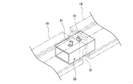
図1は、実施形態の一例である太陽光発電装置10の平面図である。図1等では、太陽光発電装置10が取り付けられる屋根100(図4参照)の軒棟方向を矢印X、軒棟方向と略垂直な桁方向を矢印Yで示す。図1に例示するように、太陽光発電装置10は、太陽電池モジュール11A,11Bを含む複数の太陽電池モジュール11と、太陽光発電装置用架台1とを備える。太陽電池モジュール11Aは、太陽電池パネル12A(第1の太陽電池パネル)と、当該パネルの周縁部に設置されたモジュールフレーム13A(第1のモジュールフレーム)とを有する(太陽電池モジュール11Bについても同様)。本実施形態では、全ての太陽電池モジュール11が同じ形状、同じ寸法を有するものとする。   FIG. 1 is a plan view of a solar power generation device 10 that is an example of an embodiment. In FIG. 1 etc., the eaves direction of the roof 100 (refer FIG. 4) to which the solar power generation device 10 is attached is shown by the arrow X, and the girder direction substantially perpendicular to the eaves direction is shown by the arrow Y. As illustrated in FIG. 1, the solar power generation device 10 includes a plurality of solar cell modules 11 including solar cell modules 11 </ b> A and 11 </ b> B, and the solar power generation device mount 1. The solar cell module 11A includes a solar cell panel 12A (first solar cell panel) and a module frame 13A (first module frame) installed on the peripheral edge of the panel (the same applies to the solar cell module 11B). ). In this embodiment, all the solar cell modules 11 shall have the same shape and the same dimension.

本明細書では、説明の便宜上、屋根100の軒棟方向に隣り合って配置される2枚の太陽電池モジュール11のうち、軒側に配置されるモジュールを太陽電池モジュール11A、棟側に配置されるモジュールを太陽電池モジュール11Bとする。   In the present specification, for convenience of explanation, of the two solar cell modules 11 arranged adjacent to each other in the eave building direction of the roof 100, the module arranged on the eave side is arranged on the solar cell module 11A, the building side. This module is referred to as a solar cell module 11B.

太陽光発電装置10は、太陽光発電装置用架台1として、屋根100の桁方向に沿って設けられる長尺状の横桟部材19を備える。横桟部材19は、太陽電池モジュール11Aの周縁部と太陽電池モジュール11Bの周縁部とを係合する複数の固定金具20と、複数の固定金具20の位置をスライド調整可能なガイドレール溝35を有するフレーム本体30とを備える。フレーム本体30は、太陽電池モジュール11A,11Bの周縁部が載置される長尺状の部材である。横桟部材19は、固定金具20がフレーム本体30の長手方向に間隔をあけて複数設置されてなる。   The solar power generation device 10 includes a long horizontal beam member 19 provided along the girder direction of the roof 100 as the solar power generation device mount 1. The crosspiece member 19 includes a plurality of fixing brackets 20 that engage the peripheral edge of the solar cell module 11A and the peripheral edge of the solar cell module 11B, and a guide rail groove 35 that allows the positions of the plurality of fixing brackets 20 to be slidably adjusted. And a frame body 30 having the same. The frame body 30 is a long member on which the peripheral portions of the solar cell modules 11A and 11B are placed. The crosspiece member 19 includes a plurality of fixing brackets 20 arranged at intervals in the longitudinal direction of the frame body 30.

太陽光発電装置10は、横桟部材19を用いて複数の太陽電池モジュール11を屋根100に取り付けることで構成される。横桟部材19は、屋根100の軒棟方向に太陽電池モジュール11の軒棟方向長さに対応する間隔をあけて複数配置され、また屋根100の桁方向にも複数配置される。横桟部材19は、2枚の太陽電池モジュール11A,11Bの境界部に設けられるが、太陽光発電装置10の軒側端部及び棟側端部に設けられてもよい。太陽光発電装置10の軒側端部及び棟側端部は専用の横桟部材で固定されてもよい。   The solar power generation device 10 is configured by attaching a plurality of solar cell modules 11 to a roof 100 using a cross beam member 19. A plurality of crosspiece members 19 are arranged in the eaves ridge direction of the roof 100 at intervals corresponding to the eave building direction length of the solar cell module 11, and are also arranged in the girder direction of the roof 100. The crosspiece member 19 is provided at the boundary between the two solar cell modules 11A and 11B, but may be provided at the eaves-side end and the ridge-side end of the solar power generation device 10. The eaves-side end and the ridge-side end of the solar power generation device 10 may be fixed by a dedicated crosspiece member.

太陽光発電装置10は、フレーム本体30を屋根100に固定するための縦桟部材110を備えることが好ましい。本実施形態では、太陽光発電装置用架台1が、横桟部材19と、縦桟部材110とで構成される。横桟部材19のフレーム本体30は、縦桟部材110上に固定され、縦桟部材110を介して屋根100に固定されている。縦桟部材110は、フレーム本体30よりも短尺の部材であって、屋根100の軒棟方向に沿って取り付けられる。縦桟部材110は、例えば1本のフレーム本体30に2つずつ取り付けられる。縦桟部材110を設置して、フレーム本体30と屋根材101(図4参照)との間に隙間を形成することで、太陽光発電装置10の下に雨水等が溜まることを抑制できる。   It is preferable that the solar power generation device 10 includes a vertical beam member 110 for fixing the frame body 30 to the roof 100. In the present embodiment, the solar power generation apparatus gantry 1 includes a horizontal beam member 19 and a vertical beam member 110. The frame main body 30 of the horizontal beam member 19 is fixed on the vertical beam member 110, and is fixed to the roof 100 via the vertical beam member 110. The vertical beam member 110 is a member that is shorter than the frame body 30 and is attached along the eaves-ridge direction of the roof 100. For example, two vertical beam members 110 are attached to one frame main body 30. By installing the vertical beam member 110 and forming a gap between the frame main body 30 and the roof material 101 (see FIG. 4), it is possible to suppress rainwater or the like from accumulating under the solar power generation device 10.

太陽電池モジュール11は、複数の太陽電池セルがガラス基板、樹脂基板等の保護部材で挟持された太陽電池パネル12を有し、当該パネルの四方を囲むようにモジュールフレーム13が設置された構造を有する。モジュールフレーム13は、太陽電池パネル12の周縁部を保護すると共に、横桟部材19に対する太陽電池モジュール11の固定に利用される。太陽電池モジュール11及び太陽電池パネル12は、例えば平面視で長方形を呈するが、その平面視形状は特に限定されず、正方形状、五角形状等であってもよい。   The solar cell module 11 includes a solar cell panel 12 in which a plurality of solar cells are sandwiched between protective members such as a glass substrate and a resin substrate, and a module frame 13 is installed so as to surround four sides of the panel. Have. The module frame 13 protects the peripheral edge of the solar cell panel 12 and is used for fixing the solar cell module 11 to the crosspiece member 19. For example, the solar cell module 11 and the solar cell panel 12 have a rectangular shape in plan view, but the shape in plan view is not particularly limited, and may be a square shape, a pentagonal shape, or the like.

太陽光発電装置10では、各太陽電池モジュール11の短辺が軒棟方向に略平行となり、かつ屋根100の桁方向に隣り合う太陽電池モジュール11の短辺同士が略接触した状態で、各太陽電池モジュール11が格子状に配置されている。また、太陽電池モジュール11A,11Bの間隙は、屋根100の桁方向に沿って直線状に形成されている。   In the solar power generation device 10, each solar cell module 11 has a short side substantially parallel to the eaves-ridge direction, and the short sides of the solar cell modules 11 adjacent to each other in the girder direction of the roof 100 are substantially in contact with each other. Battery modules 11 are arranged in a grid pattern. Further, the gap between the solar cell modules 11 </ b> A and 11 </ b> B is formed linearly along the girder direction of the roof 100.

太陽光発電装置10では、太陽電池モジュール11A,11Bの境界部に、屋根100の桁方向に沿って、即ち太陽電池モジュール11A,11Bの長辺に沿って横桟部材19が設置されている。横桟部材19のフレーム本体30上には、太陽電池モジュール11Aの棟側端部及び太陽電池モジュール11Bの軒側端部が載置され、固定金具20によって当該各モジュールがフレーム本体30上に固定される。   In the solar power generation device 10, the crosspiece member 19 is installed in the boundary part of solar cell module 11A, 11B along the beam direction of the roof 100, ie, along the long side of solar cell module 11A, 11B. On the frame main body 30 of the crosspiece member 19, the ridge side end of the solar cell module 11 </ b> A and the eaves side end of the solar cell module 11 </ b> B are mounted, and each module is fixed on the frame main body 30 by the fixing bracket 20. Is done.

横桟部材19は、太陽電池モジュール11A,11Bに係合する部分(固定金具20)と、太陽電池モジュール11A,11B等の重量、及びそれらにかかる荷重(正圧、負圧)を受容可能な剛性を有する部分(フレーム本体30)とが分離された構造を有する。固定金具20は、上述の通り、フレーム本体30の長手方向に間隔をあけてフレーム本体30に複数取り付けられている。   The crosspiece member 19 can receive the portions (fixing bracket 20) that engage with the solar cell modules 11A and 11B, the weight of the solar cell modules 11A and 11B, and the loads (positive pressure and negative pressure) applied thereto. It has a structure in which a rigid portion (frame body 30) is separated. As described above, a plurality of the fixtures 20 are attached to the frame body 30 at intervals in the longitudinal direction of the frame body 30.

即ち、固定金具20の長さは、フレーム本体30の長さよりも短く、フレーム本体30の長さの1/2倍未満であることが好ましい。フレーム本体30の長さは、例えば太陽電池モジュール11の2枚分の桁方向長さ(桁方向に沿った長さ)と同程度であってもよいが、取り扱い性、排水性等を考慮すると、太陽電池モジュール11A,11Bの桁方向長さよりも短いことが好ましい。   That is, it is preferable that the length of the fixing bracket 20 is shorter than the length of the frame body 30 and less than 1/2 times the length of the frame body 30. The length of the frame main body 30 may be approximately the same as the length in the girder direction of the two solar cell modules 11 (length along the girder direction), but in consideration of handleability, drainage, and the like. It is preferable that the length of the solar cell modules 11A and 11B is shorter than the digit direction length.

固定金具20は、例えばフレーム本体30の長さの10%〜40%の長さを有し、1本のフレーム本体30に2つ取り付けられる。2つの固定金具20は、フレーム本体30の長手方向両側において、長手方向中央から略等間隔の位置に取り付けられることが好ましい。このように、長尺状のフレーム本体30に複数の固定金具20を分割して取り付けることで、雨水等が堰き止められ難くなり、各固定金具20の間から容易に排水される。   For example, the fixing bracket 20 has a length of 10% to 40% of the length of the frame main body 30 and is attached to one frame main body 30. The two fixtures 20 are preferably attached at substantially equal intervals from the longitudinal center on both longitudinal sides of the frame body 30. Thus, by attaching the plurality of fixing brackets 20 to the long frame body 30 in a divided manner, it becomes difficult for rainwater or the like to be dammed and drained easily from between the fixing brackets 20.

図1に示す例では、太陽電池モジュール11A,11Bの境界部毎に、フレーム本体30が1本ずつ設置されている。また、屋根100の桁方向に並んで複数のフレーム本体30が設置されている。そして、屋根100の桁方向に並ぶ複数のフレーム本体30は、ジョイント金具50によって桁方向に所定の間隔をあけて互いに連結されている。フレーム本体30をこのように隙間をあけて連結することで、当該隙間を雨水等が通って屋根100の軒側に流れ易くなり、太陽光発電装置10の排水性が向上する。   In the example shown in FIG. 1, one frame body 30 is installed at each boundary between the solar cell modules 11 </ b> A and 11 </ b> B. A plurality of frame main bodies 30 are installed side by side in the girder direction of the roof 100. The plurality of frame main bodies 30 arranged in the spar direction of the roof 100 are connected to each other at a predetermined interval in the spar direction by the joint fitting 50. By connecting the frame main body 30 with a gap in this way, rainwater or the like can easily flow through the gap toward the eaves side of the roof 100, and the drainage of the solar power generation device 10 is improved.

図2Aは、ジョイント金具50の斜視図であって、ジョイント金具50により連結される2本のフレーム本体30を一点鎖線で示している。図2Aに例示するように、屋根100の桁方向に並ぶ複数のフレーム本体30は、ジョイント金具50によって連結される。フレーム本体30及びジョイント金具50はいずれも角筒形状を有するが、ジョイント金具50はフレーム本体30よりも一回り小さく、各フレーム本体30の中空部31にそれぞれ挿入される。ジョイント金具50は、各フレーム本体30にネジ止めされてもよい。   FIG. 2A is a perspective view of the joint fitting 50, and shows two frame bodies 30 connected by the joint fitting 50 by a one-dot chain line. As illustrated in FIG. 2A, the plurality of frame main bodies 30 arranged in the beam direction of the roof 100 are connected by a joint fitting 50. Both the frame body 30 and the joint fitting 50 have a rectangular tube shape, but the joint fitting 50 is slightly smaller than the frame body 30 and is inserted into the hollow portion 31 of each frame body 30. The joint fitting 50 may be screwed to each frame body 30.

ジョイント金具50には、2本のフレーム本体30の間隔を調整するためのストッパ51が設けられていてもよい。ストッパ51は、例えばジョイント金具50の上面に立設した突出片であって、金具の一部をカットして上方に折り曲げることにより形成される。ストッパ51は、ジョイント金具50の長手方向に所定の間隔をあけて2つ形成され、それぞれがフレーム本体30の長手方向端面に当接する。これにより、2本のフレーム本体30の接近が防止され、上記所定の間隔が形成される。なお、ストッパ51は、切込みからの水の浸入を少なくするため、下面側に形成されていてもよいし、図2Bに示す様に、切込みをフレーム本体30側に設けてもよい。   The joint fitting 50 may be provided with a stopper 51 for adjusting the interval between the two frame bodies 30. The stopper 51 is, for example, a protruding piece standing on the upper surface of the joint fitting 50, and is formed by cutting a part of the fitting and bending it upward. Two stoppers 51 are formed at predetermined intervals in the longitudinal direction of the joint fitting 50, and each of them comes into contact with the longitudinal end surface of the frame body 30. Thereby, the approach of the two frame main bodies 30 is prevented, and the predetermined interval is formed. The stopper 51 may be formed on the lower surface side in order to reduce the intrusion of water from the cut, or may be provided on the frame main body 30 side as shown in FIG. 2B.

以下、図3〜図5を参照しながら、屋根100に対する太陽光発電装置10の固定構造を構成するモジュールフレーム13及び横桟部材19(固定金具20、フレーム本体30)について詳説する。また、縦桟部材110の構成についても簡潔に説明する。   Hereinafter, with reference to FIGS. 3 to 5, the module frame 13 and the crosspiece member 19 (the fixing bracket 20 and the frame main body 30) constituting the fixing structure of the photovoltaic power generation apparatus 10 to the roof 100 will be described in detail. The configuration of the vertical beam member 110 will also be briefly described.

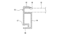
図3は、太陽電池モジュール11の長辺に沿って取り付けられたモジュールフレーム13の幅方向断面図である。図3に例示するように、モジュールフレーム13は、太陽電池パネル12の周縁部が挿し込まれる内溝16と、太陽電池パネル12側と反対側の外側に向かって開口した外溝17とを有する。モジュールフレーム13は、例えば略角筒形状を呈する本体部14と、本体部14上に設けられた略L字状の鍔部15とを有する。   FIG. 3 is a cross-sectional view in the width direction of the module frame 13 attached along the long side of the solar cell module 11. As illustrated in FIG. 3, the module frame 13 includes an inner groove 16 into which the peripheral edge of the solar cell panel 12 is inserted, and an outer groove 17 that opens toward the outer side opposite to the solar cell panel 12 side. . The module frame 13 includes, for example, a main body portion 14 having a substantially rectangular tube shape, and a substantially L-shaped flange portion 15 provided on the main body portion 14.

モジュールフレーム13では、本体部14の上面と鍔部15との間に内溝16が形成されている。内溝16に挿入される太陽電池パネル12と本体部14、鍔部15との隙間には接着剤又はシーリング材が充填されていてもよい。また、本体部14の外側に向いた側壁部には外溝17が形成されている。   In the module frame 13, an inner groove 16 is formed between the upper surface of the main body portion 14 and the flange portion 15. An adhesive or a sealing material may be filled in a gap between the solar cell panel 12 inserted into the inner groove 16, the main body portion 14, and the flange portion 15. An outer groove 17 is formed in the side wall portion facing the outside of the main body portion 14.

外溝17は、太陽電池パネル12と反対側、即ち太陽電池モジュール11の外側を向いて開口した溝である。外溝17は、モジュールフレーム13の下部において、モジュールフレーム13の長手方向に沿って形成されている。外溝17は、固定金具20の一部(後述の凸状部23,24)が挿入される溝であって、凸状部23,24を収容できる奥行深さ及び幅(上下方向長さ)を有する。なお、モジュールフレーム13の形状は図3に例示する形状に限定されない。   The outer groove 17 is a groove opened toward the opposite side of the solar cell panel 12, that is, toward the outside of the solar cell module 11. The outer groove 17 is formed in the lower part of the module frame 13 along the longitudinal direction of the module frame 13. The outer groove 17 is a groove into which a part of the fixing fitting 20 (protruding portions 23 and 24 described later) is inserted, and the depth and width (vertical length) that can accommodate the protruding portions 23 and 24. Have The shape of the module frame 13 is not limited to the shape illustrated in FIG.

図4は、横桟部材19及び縦桟部材110を示す分解斜視図である。図4で例示するように、太陽光発電装置10では、縦桟部材110が屋根100に敷設された屋根材101上に軒棟方向に沿うように固定され、フレーム本体30が縦桟部材110と略直交するように設けられて縦桟部材110上に固定される。固定金具20は、フレーム本体30のガイドレール溝35に挿入され、固定金具20の位置はフレーム本体30の長手方向に沿ってスライド調整可能である。このように、固定金具20をフレーム本体30から取り外し可能とすることで、各部材の積載が容易になり、保管性、搬送性が向上する。また、梱包の簡素化を図ることができ、施工の際の荷解きや荷揚げなどの省力化も可能となる。   FIG. 4 is an exploded perspective view showing the horizontal beam member 19 and the vertical beam member 110. As illustrated in FIG. 4, in the solar power generation device 10, the vertical beam member 110 is fixed on the roof material 101 laid on the roof 100 along the eaves ridge direction, and the frame body 30 is connected to the vertical beam member 110. It is provided so as to be substantially orthogonal and fixed on the vertical beam member 110. The fixing bracket 20 is inserted into the guide rail groove 35 of the frame body 30, and the position of the fixing bracket 20 can be adjusted by sliding along the longitudinal direction of the frame body 30. Thus, by making the fixing bracket 20 detachable from the frame main body 30, it becomes easy to stack each member, and the storability and transportability are improved. In addition, simplification of packaging can be achieved, and labor saving such as unpacking and unloading during construction can also be achieved.

固定金具20は、フレーム本体30と同様に、長尺状の金具であって、その長手方向が屋根100の桁方向に沿うように設けられる。上述の通り、固定金具20の長さはフレーム本体30の長さよりも短く、固定金具20はフレーム本体30の長手方向に間隔をあけて複数取り付けられる。太陽電池モジュール11を横桟部材で固定する場合、横桟部材によって雨水等が堰き止められ易いが、フレーム本体30よりも短い固定金具20を桁方向に間隔をあけて複数設けることで雨水等が堰き止められ難くなり排水性が向上する。   The fixing metal fitting 20 is a long metal fitting similar to the frame main body 30, and is provided such that its longitudinal direction is along the girder direction of the roof 100. As described above, the length of the fixture 20 is shorter than the length of the frame body 30, and a plurality of fixtures 20 are attached at intervals in the longitudinal direction of the frame body 30. When the solar cell module 11 is fixed by the horizontal beam member, rainwater or the like is easily dammed by the horizontal beam member. However, rainwater or the like can be obtained by providing a plurality of fixing brackets 20 shorter than the frame body 30 at intervals in the digit direction. It becomes difficult to dam and drainage improves.

固定金具20は、ガイドレール溝35に挿入されるベース部21と、ベース部21上に立設する立壁部22とを有する。ベース部21は、例えば一定の幅を有する板状に形成される。立壁部22は、ベース部21の幅方向中央部に立設し、ベース部21に対して略垂直に形成されることが好ましい。立壁部22は、ネジ26(図5参照)が挿通される貫通孔25を有し、モジュールフレーム13にネジ止めされてもよい。また、立壁部22は、太陽電池モジュール11A,11Bの周縁部に挟持されることが好ましい。   The fixture 20 includes a base portion 21 that is inserted into the guide rail groove 35 and a standing wall portion 22 that stands on the base portion 21. The base portion 21 is formed in a plate shape having a certain width, for example. The standing wall portion 22 is preferably erected at the center in the width direction of the base portion 21 and is formed substantially perpendicular to the base portion 21. The standing wall portion 22 has a through hole 25 through which a screw 26 (see FIG. 5) is inserted, and may be screwed to the module frame 13. Moreover, it is preferable that the standing wall part 22 is clamped by the peripheral part of solar cell module 11A, 11B.

また、固定金具20は、立壁部22から屋根100の軒側に突出する凸状部23と、立壁部22から屋根100の棟側に突出する凸状部24とを有する。凸状部23,24は、立壁部22の略同じ高さにおいて互いに反対方向に突出し、いずれも立壁部22に対して略垂直に略同じ突出長さで形成されることが好ましい。凸状部23,24は、例えばベース部21との間に所定の隙間をあけて、ベース部21と略平行に形成される。凸状部23,24は、互いに対向する太陽電池モジュール11A,11Bの周縁部の側壁部にそれぞれ形成された溝(外溝17A,17B)に挿し込まれる。   In addition, the fixing bracket 20 includes a convex portion 23 that protrudes from the standing wall portion 22 toward the eaves side of the roof 100, and a convex portion 24 that protrudes from the standing wall portion 22 toward the ridge side of the roof 100. It is preferable that the convex portions 23 and 24 protrude in directions opposite to each other at substantially the same height of the standing wall portion 22, and both are formed with substantially the same protruding length substantially perpendicular to the standing wall portion 22. The convex portions 23 and 24 are formed substantially parallel to the base portion 21 with a predetermined gap between the convex portions 23 and 24, for example. The convex portions 23 and 24 are inserted into grooves (outer grooves 17A and 17B) formed in the side wall portions of the peripheral edge portions of the solar cell modules 11A and 11B facing each other.

ベース部21、立壁部22、及び凸状部23,24は、固定金具20の一部に形成されてもよいが、好ましくは固定金具20の全長にわたって形成される。固定金具20は、例えば鉄、又はアルミニウムを主成分とする金属で構成される。   The base portion 21, the standing wall portion 22, and the convex portions 23 and 24 may be formed on a part of the fixing bracket 20, but are preferably formed over the entire length of the fixing bracket 20. The fixture 20 is made of, for example, a metal whose main component is iron or aluminum.

フレーム本体30は、固定金具20よりも長い長尺状の金具であって、略角筒形状を有することが好ましい。角筒形状とすることで、フレームの断面積に比して断面2次モーメントの断面係数が大きくなり、軽量で耐荷重性に優れたフレームとなる。フレーム本体30は、例えばアルミニウムを主成分とする金属で構成される。   The frame body 30 is a long metal fitting that is longer than the fixed metal fitting 20 and preferably has a substantially rectangular tube shape. By adopting the rectangular tube shape, the section modulus of the second moment of section is larger than the sectional area of the frame, and the frame is lightweight and excellent in load resistance. The frame body 30 is made of a metal whose main component is aluminum, for example.

フレーム本体30は、長手方向に沿って形成された中空部31と、ガイドレール溝35とを有する。ガイドレール溝35は、中空部31よりもフレーム本体30の上部において、フレーム本体30の長手方向に沿って形成されている。中空部31及びガイドレール溝35は、フレーム本体30の全長にわたって形成されることが好ましい。屋根100の桁方向に並ぶフレーム本体30は、上述の通り、中空部31よりも一回り小さなジョイント金具50を中空部31に挿し込んで連結されている。   The frame main body 30 includes a hollow portion 31 formed along the longitudinal direction and a guide rail groove 35. The guide rail groove 35 is formed along the longitudinal direction of the frame body 30 at an upper portion of the frame body 30 than the hollow portion 31. The hollow portion 31 and the guide rail groove 35 are preferably formed over the entire length of the frame body 30. As described above, the frame main bodies 30 arranged in the girder direction of the roof 100 are connected by inserting the joint fitting 50 that is slightly smaller than the hollow portion 31 into the hollow portion 31.

フレーム本体30は、中空部31の四方を囲むように、フレーム底部32、一対のフレーム側壁部33、及び隔壁部34が形成された構造を有する。隔壁部34は、中空部31とガイドレール溝35との間に設けられ、ガイドレール溝35の底部を形成している。一対のフレーム側壁部33は、フレーム底部32及び隔壁部34に対して略垂直に形成されることが好ましい。   The frame body 30 has a structure in which a frame bottom portion 32, a pair of frame side wall portions 33, and a partition wall portion 34 are formed so as to surround four sides of the hollow portion 31. The partition wall portion 34 is provided between the hollow portion 31 and the guide rail groove 35 and forms the bottom portion of the guide rail groove 35. The pair of frame side wall portions 33 are preferably formed substantially perpendicular to the frame bottom portion 32 and the partition wall portion 34.

ガイドレール溝35は、固定金具20の立壁部22を通すための開口部36と、開口部36よりも幅広に形成された拡幅部37とを有する。開口部36は、フレーム本体30の全長にわたって略一定の幅で形成される細長い開口部であって、モジュールフレーム13が載置されるフレーム本体30の上面に形成されている。拡幅部37は、固定金具20のベース部21が挿入される部分であって、開口部36の下に形成されている。   The guide rail groove 35 has an opening 36 through which the standing wall portion 22 of the fixture 20 is passed, and a widened portion 37 formed wider than the opening 36. The opening 36 is an elongated opening formed with a substantially constant width over the entire length of the frame body 30, and is formed on the upper surface of the frame body 30 on which the module frame 13 is placed. The widened portion 37 is a portion into which the base portion 21 of the fixture 20 is inserted, and is formed under the opening 36.

フレーム本体30には、開口部36の幅方向両側に一対の鉤部38が形成されている。固定金具20は、この鉤部38によって拡幅部37に挿入されたベース部21が上方に抜けない状態となり、固定金具20の位置はガイドレール溝35によってスライド調整可能である。ガイドレール溝35は、隔壁部34の幅方向両端から上方に延び、内側に折れ曲がった断面略L字状の鉤部38によって形成されているといえる。   The frame body 30 is formed with a pair of flanges 38 on both sides in the width direction of the opening 36. The fixing bracket 20 is in a state where the base portion 21 inserted into the widened portion 37 cannot be removed upward by the flange portion 38, and the position of the fixing bracket 20 can be adjusted by a guide rail groove 35. It can be said that the guide rail groove 35 is formed by a flange portion 38 that extends upward from both ends in the width direction of the partition wall portion 34 and is bent inward.

また、フレーム本体30は、幅方向に張り出した鍔部39を有していてもよい。鍔部39は、フレーム本体30の幅方向一方側のみに設けられていてもよいが、本実施形態では、フレーム本体30の幅方向両側に設けられており、各フレーム側壁部33の下部から幅方向外側にそれぞれ張り出している。鍔部39は、先端部が上方に向かって折れ曲がった断面略L字状に形成されている。フレーム本体30は、この鍔部39を利用して縦桟部材110に固定される。   Further, the frame main body 30 may have a flange 39 protruding in the width direction. The flanges 39 may be provided only on one side in the width direction of the frame body 30, but in this embodiment, the flanges 39 are provided on both sides in the width direction of the frame body 30, Each projecting outward. The collar portion 39 is formed in a substantially L-shaped cross section with the tip portion bent upward. The frame main body 30 is fixed to the vertical beam member 110 using the flange 39.

縦桟部材110は、ネジ114で屋根材101上に固定されるスレート金具111と、スレート金具111上にボルト及びナットで固定される押え金具112とを有する。縦桟部材110は、屋根100の軒棟方向及び桁方向に並んで複数取り付けられている。スレート金具111は、押え金具112の位置をスライド調整可能なガイドレール溝113を有する。押え金具112は、逆U字形状を有する金具であって、フレーム本体30の鍔部39を上から押え付けてフレーム本体30をスレート金具111上に固定する。   The vertical beam member 110 includes a slate fitting 111 that is fixed on the roofing material 101 with screws 114 and a press fitting 112 that is fixed on the slate fitting 111 with bolts and nuts. A plurality of vertical beam members 110 are attached side by side in the eaves ridge direction and the girder direction of the roof 100. The slate fitting 111 has a guide rail groove 113 in which the position of the holding fitting 112 can be adjusted by sliding. The presser fitting 112 is a metal fitting having an inverted U-shape, and presses the flange portion 39 of the frame main body 30 from above to fix the frame main body 30 on the slate metal fitting 111.

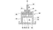
図5は、図1中のAA線断面図である。図5に例示するように、太陽電池モジュール11A,11Bのモジュールフレーム13A,13Bは、フレーム本体30上に載置され、固定金具20によってフレーム本体30に固定されている。固定金具20は、ベース部21がガイドレール溝35に挿入されることでフレーム本体30に固定される。なお、固定金具20はフレーム本体30に対してネジ止めされてもよい(後述の図9参照)。   FIG. 5 is a cross-sectional view taken along line AA in FIG. As illustrated in FIG. 5, the module frames 13 </ b> A and 13 </ b> B of the solar cell modules 11 </ b> A and 11 </ b> B are placed on the frame main body 30 and fixed to the frame main body 30 by the fixing bracket 20. The fixing bracket 20 is fixed to the frame body 30 by inserting the base portion 21 into the guide rail groove 35. The fixing bracket 20 may be screwed to the frame body 30 (see FIG. 9 described later).

フレーム本体30上には、ガイドレール溝35の開口部36から突出した固定金具20の立壁部22が立設している。そして、モジュールフレーム13A,13Bは、立壁部22を挟んでフレーム本体30上に対向配置されている。モジュールフレーム13A,13Bは、互いに対向する側壁部に形成された外溝17A,17Bをそれぞれ有する。立壁部22の開口部36から突出した部分には、モジュールフレーム13A側に突出した凸状部23と、モジュールフレーム13B側に突出した凸状部24とが形成されている。   On the frame main body 30, an upright wall portion 22 of the fixing bracket 20 protruding from the opening portion 36 of the guide rail groove 35 is erected. The module frames 13A and 13B are disposed opposite to each other on the frame main body 30 with the standing wall portion 22 interposed therebetween. The module frames 13A and 13B have outer grooves 17A and 17B formed in side wall portions facing each other. A protruding portion 23 protruding toward the module frame 13A and a protruding portion 24 protruding toward the module frame 13B are formed at a portion protruding from the opening 36 of the standing wall portion 22.

固定金具20は、凸状部23がモジュールフレーム13Aの外溝17Aに、凸状部24がモジュールフレーム13Bの外溝17Bにそれぞれ挿入されることで、各モジュールフレーム13A,13Bに係合している。この状態で、モジュールフレーム13Aの底板18Aは凸状部23とフレーム本体30の鉤部38との間に挿し込まれている。即ち、固定金具20は、凸状部23が外溝17Aに挿入されると共に、底板18Aを上から押え付けることで、モジュールフレーム13Aに係合している。同様に、モジュールフレーム13Bの底板18Bは凸状部24とフレーム本体30の鉤部38との間に挿し込まれている。   The fixing bracket 20 is engaged with each of the module frames 13A and 13B by inserting the convex portion 23 into the outer groove 17A of the module frame 13A and the convex portion 24 into the outer groove 17B of the module frame 13B. Yes. In this state, the bottom plate 18 </ b> A of the module frame 13 </ b> A is inserted between the convex portion 23 and the flange portion 38 of the frame body 30. That is, the fixing bracket 20 is engaged with the module frame 13A by inserting the convex portion 23 into the outer groove 17A and pressing the bottom plate 18A from above. Similarly, the bottom plate 18 </ b> B of the module frame 13 </ b> B is inserted between the convex portion 24 and the flange portion 38 of the frame body 30.

凸状部23,24の突出長さは、外溝17A,17Bの奥行深さよりも短いことが好ましい。この場合、立壁部22がモジュールフレーム13Aと接触するまで、凸状部23を外溝17Aに挿入することができる。凸状部24についても同様に、立壁部22がモジュールフレーム13Bと接触するまで外溝17Bに挿入される。図4に示す例では、固定金具20の幅が、ベース部21において最大となっているが、凸状部23,24が形成された部分で最大となっていてもよい。   The protruding lengths of the convex portions 23 and 24 are preferably shorter than the depths of the outer grooves 17A and 17B. In this case, the convex portion 23 can be inserted into the outer groove 17A until the standing wall portion 22 contacts the module frame 13A. Similarly, the convex portion 24 is inserted into the outer groove 17B until the standing wall portion 22 contacts the module frame 13B. In the example shown in FIG. 4, the width of the fixture 20 is maximum at the base portion 21, but may be maximum at portions where the convex portions 23 and 24 are formed.

立壁部22は、凸状部23,24が外溝17A,17Bにそれぞれ挿入された状態で、モジュールフレーム13A,13Bによって挟持されていることが好ましい。立壁部22がモジュールフレーム13A,13Bによって挟持されることで、太陽電池モジュール11A,11Bの間隔が小さくなりモジュールの搭載効率が向上すると共に、横桟部材19の耐荷重性も向上する。   The standing wall portion 22 is preferably sandwiched between the module frames 13A and 13B in a state where the convex portions 23 and 24 are inserted into the outer grooves 17A and 17B, respectively. Since the standing wall portion 22 is sandwiched between the module frames 13A and 13B, the interval between the solar cell modules 11A and 11B is reduced, the module mounting efficiency is improved, and the load resistance of the crosspiece member 19 is also improved.

立壁部22は、貫通孔25に挿通されるネジ26を用いてモジュールフレーム13A,13Bの一方にネジ止めされてもよい。例えば、ネジ26には皿ネジが用いられ、貫通孔25は皿ネジの頭部を収容可能な形状を有する。ネジ26の軸部は、モジュールフレーム13Aの本体部14A内に収容されていてもよい。   The standing wall portion 22 may be screwed to one of the module frames 13 </ b> A and 13 </ b> B using a screw 26 inserted through the through hole 25. For example, a countersunk screw is used as the screw 26, and the through hole 25 has a shape that can accommodate the head of the countersunk screw. The shaft portion of the screw 26 may be accommodated in the main body portion 14A of the module frame 13A.

本実施形態では、立壁部22の上端がモジュールフレーム13A,13Bの上端よりも低い位置に存在するが、立壁部22の上端とモジュールフレーム13A,13Bの上端の高さが一致するような高さで立壁部22を形成してもよい。また、立壁部22を高くして雪止め壁として利用してもよい(後述の図10参照)。   In the present embodiment, the upper end of the standing wall portion 22 exists at a position lower than the upper ends of the module frames 13A and 13B. However, the height is such that the upper end of the standing wall portion 22 and the upper ends of the module frames 13A and 13B coincide. The standing wall portion 22 may be formed. Moreover, you may raise the standing wall part 22 and may utilize as a snow stop wall (refer FIG. 10 mentioned later).

なお、凸状部23,24には、モジュールフレーム13A,13Bに食い込む突起が形成されていてもよい。例えば、凸状部23,24は下方に突出して底板18A,18Bに食い込む突起を有していてもよい。このような突起を設けることで、固定金具20とモジュールフレーム13A,13Bとの結合力が向上し、また突起を利用してアースをとることもできる。同様に、ベース部21にもフレーム本体30に食い込む突起が形成されていてもよい。   In addition, the protrusions 23 and 24 may be formed with protrusions that bite into the module frames 13A and 13B. For example, the convex portions 23 and 24 may have protrusions that protrude downward and bite into the bottom plates 18A and 18B. By providing such a projection, the coupling force between the fixture 20 and the module frames 13A and 13B is improved, and the projection can be used to ground. Similarly, a protrusion that bites into the frame body 30 may be formed on the base portion 21.

フレーム本体30は、フレーム底部32を貫通して形成され、中空部31と連通する底部排水孔40を有していてもよい。中空部31には、例えば長手方向両端の開口から雨水等が浸入する場合があるため、底部排水孔40を設けることで、中空部31に浸入した水を排出することができる。底部排水孔40は、フレーム底部32において、中空部31の軒側端部に形成されることが好ましい。底部排水孔40は中空部31の軒側端部だけに形成されてもよいが、フレーム本体30をどちら向きでも使用可能とし、施工性の向上、施工ミスの防止を図るためには、底部排水孔40は中空部31の幅方向両端部に形成されることが好適である。   The frame body 30 may have a bottom drain hole 40 formed through the frame bottom 32 and communicating with the hollow portion 31. For example, rainwater or the like may enter the hollow portion 31 from the openings at both ends in the longitudinal direction. Therefore, the water that has entered the hollow portion 31 can be discharged by providing the bottom drain hole 40. The bottom drain hole 40 is preferably formed at the eave side end of the hollow portion 31 in the frame bottom portion 32. The bottom drain hole 40 may be formed only at the eaves side end of the hollow portion 31. However, in order to enable the frame body 30 to be used in either direction and to improve workability and prevent construction mistakes, The holes 40 are preferably formed at both ends in the width direction of the hollow portion 31.

底部排水孔40は、円形状、正方形状等であってもよいが、好ましくはフレーム本体30の長手方向に沿ってスリット状に形成される。底部排水孔40をスリット状に形成することで、フレーム本体30の強度を低下させることなく、また粉塵等が詰まり難く、良好な排水性を得ることができる。底部排水孔40は、水が浸入し易いフレーム本体30の長手方向両端部に形成されてもよく、水を排出し難いフレーム本体30の長手方向中央部に形成されてもよい。例えば、底部排水孔40は、フレーム本体30の全長の10%〜50%の長さで形成され、中空部31の幅方向両端から中空部31の幅の20%以下の幅で形成される。底部排水孔40は、フレーム本体30の長手方向に沿って複数形成されてもよい。   The bottom drain hole 40 may be circular, square, or the like, but is preferably formed in a slit shape along the longitudinal direction of the frame body 30. By forming the bottom drain hole 40 in a slit shape, the strength of the frame main body 30 is not reduced, and dust and the like are hardly clogged, and good drainage can be obtained. The bottom drain holes 40 may be formed at both ends in the longitudinal direction of the frame main body 30 where water is likely to enter, or may be formed at the central portion in the longitudinal direction of the frame main body 30 where it is difficult to discharge water. For example, the bottom drain hole 40 is formed with a length of 10% to 50% of the entire length of the frame body 30, and is formed with a width of 20% or less of the width of the hollow portion 31 from both ends in the width direction of the hollow portion 31. A plurality of bottom drain holes 40 may be formed along the longitudinal direction of the frame body 30.

フレーム本体30には、モジュールフレーム13Aの移動を規制するための移動規制金具55が取り付けられていてもよい。移動規制金具55は、フレーム本体30の軒側に位置するフレーム側壁部33にネジ56を用いて固定できる。移動規制金具55は、中間部が外側に小さく折れ曲がった板状の金具であって、フレーム本体30の上端よりも上方に突出し、モジュールフレーム13Aの本体部14Aの近傍で本体部14Aと対向するように設けられることが好ましい。   The frame main body 30 may be attached with a movement restricting metal fitting 55 for restricting the movement of the module frame 13A. The movement restricting metal fitting 55 can be fixed to the frame side wall 33 located on the eave side of the frame main body 30 by using screws 56. The movement restricting metal fitting 55 is a plate-like metal fitting whose middle portion is bent slightly outward, protrudes upward from the upper end of the frame main body 30, and faces the main body portion 14A in the vicinity of the main body portion 14A of the module frame 13A. It is preferable to be provided.

図5に示す例では、固定金具20がモジュールフレーム13Aにネジ止めされているため、太陽電池モジュール11Aの棟側端部は持ち上がり難く負圧に強いが、移動規制金具55を設けることで、さらに耐荷重性が向上する。   In the example shown in FIG. 5, since the fixture 20 is screwed to the module frame 13A, the ridge side end of the solar cell module 11A is difficult to lift and is resistant to negative pressure. Load resistance is improved.

太陽光発電装置10によれば、固定金具20とフレーム本体30とで構成される横桟部材19を用いることによって、良好な排水性を確保することができる。横桟部材19は、固定金具20がフレーム本体30の長手方向に間隔をあけて複数設置された構造を有するので、各固定金具20の間から雨水等が軒側に流れる。また、ジョイント金具50により屋根100の桁方向に間隔をあけてフレーム本体30を連結することで、雨水等の排水性がさらに向上する。   According to the solar power generation device 10, good drainage can be ensured by using the cross rail member 19 configured by the fixing bracket 20 and the frame main body 30. Since the crosspiece member 19 has a structure in which a plurality of fixing brackets 20 are installed at intervals in the longitudinal direction of the frame body 30, rainwater or the like flows from between the fixing brackets 20 to the eaves side. Moreover, drainage performance, such as rain water, further improves by connecting the frame main body 30 with a gap in the girder direction of the roof 100 by the joint fitting 50.

このように、横桟部材19は雨水等を堰き止め難い構造であるため、例えば太陽電池モジュール11上に粉塵等が溜まり難く、太陽光発電装置10の美観を長期にわたって維持でき、また太陽電池モジュール11の汚れに伴う発電効率の低下も抑制可能である。冬場では水の凍結により太陽電池モジュール11等が破損するおそれがあるが、太陽光発電装置10は水が溜まり難い構造であるため、水の凍結による装置の破損も十分に抑制される。   Thus, since the crosspiece member 19 has a structure in which it is difficult to block rainwater or the like, for example, dust or the like hardly accumulates on the solar cell module 11, and the aesthetic appearance of the solar power generation device 10 can be maintained over a long period of time. It is also possible to suppress a decrease in power generation efficiency due to 11 contamination. In winter, the solar cell module 11 and the like may be damaged due to water freezing. However, since the solar power generation device 10 has a structure in which water does not easily accumulate, damage to the device due to water freezing is sufficiently suppressed.

以下、図6〜図10を参照しながら、実施形態の他の一例について説明する。以下では、上述の実施形態と同様の構成要素には同じ符号を用いて重複する説明を省略し、主に上述の実施形態との相違点を説明する。   Hereinafter, another example of the embodiment will be described with reference to FIGS. Hereinafter, the same components as those in the above-described embodiment are denoted by the same reference numerals, and redundant description is omitted, and differences from the above-described embodiment will be mainly described.

図6に例示する架台フレーム60は、中空部31と、固定金具20の位置をスライド調整可能なガイドレール溝65とを有する点で、フレーム本体30と共通する。一方、ガイドレール溝65が、架台フレーム60の長手方向に沿って溝底部に形成された排水路67を有する点で、フレーム本体30と異なる。排水路67は、ガイドレール溝65の底部を構成する隔壁部66の上面に形成された窪みであって、ガイドレール溝65の長手方向に雨水等を流れ易くする機能を有する。   The gantry frame 60 illustrated in FIG. 6 is common to the frame main body 30 in that it includes a hollow portion 31 and a guide rail groove 65 that can slide adjust the position of the fixing bracket 20. On the other hand, the guide rail groove 65 is different from the frame body 30 in that the guide rail groove 65 has a drainage channel 67 formed in the groove bottom along the longitudinal direction of the gantry frame 60. The drainage channel 67 is a depression formed on the upper surface of the partition wall portion 66 constituting the bottom portion of the guide rail groove 65, and has a function of facilitating the flow of rainwater or the like in the longitudinal direction of the guide rail groove 65.

ガイドレール溝65に雨水等が浸入した場合に、例えば雨水等がガイドレール溝65に沿って流れるが、ガイドレール溝65には固定金具20が挿入されるため、固定金具20が固定された部分で雨水等が堰き止められ易くなる。そこで、排水路67を形成して固定金具20との間に隙間を設けることで、雨水等が固定金具20によって堰き止められ難くなり、ガイドレール溝65における排水性が向上する。図6に示す例では、ガイドレール溝65の底部の幅方向中央部に略U字状の排水路67が形成されている。   When rainwater or the like enters the guide rail groove 65, for example, rainwater or the like flows along the guide rail groove 65, but since the fixing bracket 20 is inserted into the guide rail groove 65, the portion to which the fixing bracket 20 is fixed This makes it easier for rainwater to be dammed up. Therefore, by forming a drainage channel 67 and providing a gap between the fixing bracket 20, rainwater or the like is hardly blocked by the fixing bracket 20, and drainage performance in the guide rail groove 65 is improved. In the example shown in FIG. 6, a substantially U-shaped drainage channel 67 is formed at the center in the width direction of the bottom of the guide rail groove 65.

なお、架台フレーム60の中空部31に挿入されるジョイント金具68は、中空部31に挿入し易くするため、また材料コストの削減、軽量化等を図るために、角が面取りされていてもよい。   The joint metal fitting 68 inserted into the hollow portion 31 of the gantry frame 60 may be chamfered in order to facilitate insertion into the hollow portion 31 and to reduce the material cost and weight. .

図7に例示する架台フレーム70は、ガイドレール溝75の底部に形成された排水路77を有する点で、排水路67を有する架台フレーム60と共通する。排水路77は、排水路67と同様に、隔壁部76の上面に形成された窪みであって、架台フレーム70の長手方向に沿って形成され、ガイドレール溝75の排水性を向上させる。   The gantry frame 70 illustrated in FIG. 7 is common to the gantry frame 60 having the drainage channel 67 in that it has a drainage channel 77 formed at the bottom of the guide rail groove 75. Similar to the drainage channel 67, the drainage channel 77 is a recess formed in the upper surface of the partition wall portion 76 and is formed along the longitudinal direction of the gantry frame 70, and improves the drainage of the guide rail groove 75.

図7に示す例では、ガイドレール溝75の幅方向両端部に2本の排水路77が形成されている。各排水路77は、例えばガイドレール溝75の幅方向両端から略一定の幅で形成される。排水路77はガイドレール溝75の軒側端部だけに形成されてもよいが、フレーム本体30をどちら向きでも使用可能とし、施工性の向上、施工ミスの防止を図るためには、排水路77はガイドレール溝75の幅方向両端部に形成されることが好適である。   In the example shown in FIG. 7, two drainage channels 77 are formed at both ends in the width direction of the guide rail groove 75. Each drainage channel 77 is formed with, for example, a substantially constant width from both ends in the width direction of the guide rail groove 75. The drainage channel 77 may be formed only at the end of the eaves side of the guide rail groove 75. However, in order to make the frame main body 30 usable in any direction and to improve workability and prevent construction errors, the drainage channel 77 is preferably formed at both ends of the guide rail groove 75 in the width direction.

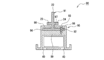
図8に例示する架台フレーム80は、ガイドレール溝85の底部を構成する隔壁部86を貫通して形成され、中空部31と連通する上部排水孔87を有する点で、フレーム本体30と異なる。上部排水孔87は、ガイドレール溝85と中空部31とを連通する貫通孔であって、ガイドレール溝85に浸入した水を中空部31に排出可能とする。この場合、フレーム底部32には下部排水孔40が形成されていることが好ましい。   The gantry frame 80 illustrated in FIG. 8 is different from the frame body 30 in that it has an upper drain hole 87 that is formed through the partition wall 86 that forms the bottom of the guide rail groove 85 and communicates with the hollow portion 31. The upper drain hole 87 is a through hole that communicates the guide rail groove 85 and the hollow portion 31, and allows water that has entered the guide rail groove 85 to be discharged to the hollow portion 31. In this case, it is preferable that a lower drain hole 40 is formed in the frame bottom portion 32.

図8に示す例では、ガイドレール溝85の開口部36と上下方向に重なる位置に上部排水孔87が形成されているが、例えばガイドレール溝85の幅方向両端部に上部排水孔87を形成することも可能である。上部排水孔87は、円形状、正方形状等であってもよいが、好ましくは架台フレーム80の長手方向に沿ってスリット状に形成される。上部排水孔87は、水が浸入し易い架台フレーム80の長手方向両端部に形成されてもよく、水を排出し難い架台フレーム80の長手方向中央部に形成されてもよい。上部排水孔87は、架台フレーム80の長手方向に沿って複数形成されてもよい。   In the example shown in FIG. 8, the upper drain holes 87 are formed at positions that overlap with the opening 36 of the guide rail groove 85 in the vertical direction. For example, the upper drain holes 87 are formed at both ends in the width direction of the guide rail groove 85. It is also possible to do. The upper drain hole 87 may be circular or square, but is preferably formed in a slit shape along the longitudinal direction of the gantry frame 80. The upper drain holes 87 may be formed at both ends in the longitudinal direction of the gantry frame 80 where water can easily enter, or may be formed at the central portion in the longitudinal direction of the gantry frame 80 where it is difficult to discharge water. A plurality of upper drain holes 87 may be formed along the longitudinal direction of the gantry frame 80.

図9に例示する横桟部材90は、固定金具91が架台フレーム95にネジ止めされている点で、横桟部材19と異なる。ネジ93を用いて固定金具91を固定することで、架台フレーム95の長手方向に沿った固定金具91の移動が確実に防止されると共に、ネジ93によってアースをとることもできる。ネジ93は、架台フレーム95の鉤部98、及び固定金具91のベース部92を貫通して、架台フレーム95の隔壁部99に固定される。ネジ93には、頭部が架台フレーム95の上面から突出しないように、皿ネジを用いてもよく、鉤部98にネジ93の頭部を収容する貫通孔が形成されていてもよい。   The horizontal beam member 90 illustrated in FIG. 9 is different from the horizontal beam member 19 in that the fixing bracket 91 is screwed to the gantry frame 95. By fixing the fixing metal 91 using the screw 93, the movement of the fixing metal 91 along the longitudinal direction of the gantry frame 95 is surely prevented, and grounding can be performed by the screw 93. The screw 93 passes through the flange portion 98 of the gantry frame 95 and the base portion 92 of the fixing bracket 91 and is fixed to the partition wall portion 99 of the gantry frame 95. The screw 93 may be a countersunk screw so that the head does not protrude from the upper surface of the gantry frame 95, and a through-hole that accommodates the head of the screw 93 may be formed in the flange 98.

図9に示す例では、ベース部92の幅方向片側に偏って立壁部22が立設しており、立壁部22の幅方向両側でベース部92の幅が異なっている。ネジ93は、立壁部22からベース部92の幅方向端部までの距離が長くなったベース部92の棟側部分に取り付けられている。なお、ガイドレール溝96の開口部97は、固定金具91の立壁部22に位置に合わせて、架台フレーム95の幅方向片側に偏って形成されている。   In the example shown in FIG. 9, the standing wall portion 22 is erected so as to be biased to one side in the width direction of the base portion 92, and the width of the base portion 92 is different on both sides of the standing wall portion 22 in the width direction. The screw 93 is attached to the ridge side portion of the base portion 92 where the distance from the standing wall portion 22 to the end portion in the width direction of the base portion 92 is increased. The opening 97 of the guide rail groove 96 is formed so as to be biased to one side in the width direction of the gantry frame 95 in accordance with the position of the standing wall portion 22 of the fixing bracket 91.

図10に例示する固定金具200は、立壁部201がモジュールフレーム13A,13Bの上端よりも上方に突出している点で、固定金具20と異なる。かかる立壁部201の突出部は、太陽電池モジュール11上に積もった雪を堰き止める雪止め壁として機能を有し、太陽電池モジュール11上から雪が一気に滑落して家屋の周囲に配置される器物が破損することを抑制する。   The fixing bracket 200 illustrated in FIG. 10 is different from the fixing bracket 20 in that the standing wall portion 201 protrudes upward from the upper ends of the module frames 13A and 13B. The protruding portion of the standing wall portion 201 has a function as a snow stop wall that blocks snow accumulated on the solar cell module 11, and the items that are arranged around the house as snow slides down from the solar cell module 11 at once. Suppresses damage.

1 太陽光発電装置用架台、10 太陽光発電装置、11,11A,11B 太陽電池モジュール、12,12A,12B 太陽電池パネル、13,13A,13B モジュールフレーム、14,14A 本体部、15 鍔部、16 内溝、17,17A,17B 外溝、18,18A,18B 底板、19 横桟部材、20 固定金具、21 ベース部、22 立壁部、23,24 凸状部、25 貫通孔、26 ネジ、30 フレーム本体、31 中空部、32 フレーム底部、33 フレーム側壁部、34 隔壁部、35 ガイドレール溝、36 開口部、37 拡幅部、38 鉤部、39 鍔部、40 底部排水孔、50 ジョイント金具、51 ストッパ、55 移動規制金具、56 ネジ、100 屋根、101 屋根材、110 縦桟部材、111 スレート金具、112 押え金具、113 ガイドレール溝、114 ネジ   DESCRIPTION OF SYMBOLS 1 Solar power generation device stand, 10 Photovoltaic power generation device, 11, 11A, 11B Solar cell module, 12, 12A, 12B Solar cell panel, 13, 13A, 13B Module frame, 14, 14A Main body part, 15 collar part, 16 Inner groove, 17, 17A, 17B Outer groove, 18, 18A, 18B Bottom plate, 19 Crosspiece member, 20 Fixing bracket, 21 Base part, 22 Standing wall part, 23, 24 Convex part, 25 Through hole, 26 Screw, 30 frame body, 31 hollow part, 32 frame bottom part, 33 frame side wall part, 34 partition wall part, 35 guide rail groove, 36 opening part, 37 widened part, 38 collar part, 39 collar part, 40 bottom part drain hole, 50 joint fitting , 51 Stopper, 55 Movement restriction bracket, 56 Screw, 100 Roof, 101 Roof material, 110 Vertical beam member, 111 s Over preparative bracket 112 pressing fixture, 113 the guide rail groove, 114 screws

Claims (8)

屋根の棟軒方向において隣接する第1の太陽電池モジュールの周縁部と第2の太陽電池モジュールの周縁部とを係合する複数の固定金具と、
前記複数の固定金具を前記屋根の棟軒方向と略垂直な桁方向に間隔を設けて支持し、前記複数の固定金具の位置をスライド調整可能なガイドレール溝を有し、前記第1及び前記第2のモジュールの周縁部が載置される長尺状のフレーム本体と、
を備え、
前記屋根の桁方向に沿って設けられる、太陽光発電装置用架台。
A plurality of fixtures for engaging the peripheral edge of the first solar cell module and the peripheral edge of the second solar cell module adjacent in the direction of the roof ridge;
The plurality of fixing brackets are supported at intervals in a girder direction substantially perpendicular to the roof ridge eave direction, and have guide rail grooves capable of slidingly adjusting the positions of the plurality of fixing brackets. An elongated frame body on which the peripheral edge of the second module is placed;
With
A stand for a solar power generation device provided along the girder direction of the roof.
前記固定金具は、
前記フレーム本体の前記ガイドレール溝に挿入されるベース部と、
前記ベース部上に立設し、前記第1及び前記第2のモジュールの周縁部に挟持される立壁部と、
前記立壁部から前記屋根の軒側及び棟側に突出し、互いに対向する前記第1及び前記第2の太陽電池モジュールの周縁部の側壁部にそれぞれ形成された溝に挿し込まれる凸状部と、
を有する、請求項1に記載の太陽光発電装置用架台。
The fixing bracket is
A base portion inserted into the guide rail groove of the frame body;
A standing wall portion standing on the base portion and sandwiched between peripheral portions of the first and second modules;
A protruding portion that protrudes from the standing wall portion to the eaves side and the ridge side of the roof and is inserted into grooves formed in the side wall portions of the peripheral portions of the first and second solar cell modules facing each other, and
The pedestal for solar power generation device according to claim 1, comprising:
前記フレーム本体は、長手方向に沿って形成された中空部を有し、
前記ガイドレール溝は、前記中空部よりも前記フレーム本体の上部において、前記フレーム本体の長手方向に沿って形成されている、請求項1又は2に記載の太陽光発電装置用架台。
The frame body has a hollow portion formed along the longitudinal direction;
The said guide rail groove | channel is a stand for solar power generation devices of Claim 1 or 2 formed along the longitudinal direction of the said frame main body in the upper part of the said frame main body rather than the said hollow part.
前記フレーム本体は、前記フレーム本体の底部を貫通して形成され、前記中空部と連通する底部排水孔を有する、請求項3に記載の太陽光発電装置用架台。   The said frame main body is a base for solar power generation devices of Claim 3 which has the bottom part drainage hole formed through the bottom part of the said frame main body, and connected with the said hollow part. 前記フレーム本体は、前記ガイドレール溝の底部を貫通して形成され、前記中空部と連通する上部排水孔を有する、請求項3又は4に記載の太陽光発電装置用架台。   The said frame main body is a stand for solar power generation devices of Claim 3 or 4 which is formed through the bottom part of the said guide rail groove | channel, and has an upper drain hole connected with the said hollow part. 前記ガイドレール溝は、前記架台フレーム本体の長手方向に沿って底部に形成された排水路を有する、請求項1〜5のいずれか1項に記載の太陽光発電装置用架台。   The said guide rail groove | channel is a base for solar power generation devices of any one of Claims 1-5 which has the drainage channel formed in the bottom part along the longitudinal direction of the said base frame main body. 前記フレーム本体の長さは、前記第1及び前記第2の太陽電池モジュールの周縁部の桁方向長さよりも短く、
前記屋根の桁方向に並ぶ複数の前記フレーム本体は、ジョイント金具によって互いに所定の隙間をあけて連結されている、請求項1〜6のいずれか1項に記載の太陽光発電装置用架台。
The length of the frame main body is shorter than the length in the digit direction of the peripheral edge of the first and second solar cell modules,
The said frame main body located in a row | line | column direction of the said roof is a stand for solar power generation devices of any one of Claims 1-6 connected with a predetermined gap mutually with the joint metal fitting.
前記立壁部は、前記第1及び前記第2のモジュールの周縁部の上端よりも上方に突出している、請求項1〜7のいずれか1項に記載の太陽光発電装置用架台。   The stand for a solar power generation device according to any one of claims 1 to 7, wherein the standing wall portion protrudes upward from the upper ends of the peripheral edge portions of the first and second modules.
JP2017059644A 2017-03-24 2017-03-24 Frame for solar power generator Pending JP2018162575A (en)

Priority Applications (1)

Application Number Priority Date Filing Date Title
JP2017059644A JP2018162575A (en) 2017-03-24 2017-03-24 Frame for solar power generator

Applications Claiming Priority (1)

Application Number Priority Date Filing Date Title
JP2017059644A JP2018162575A (en) 2017-03-24 2017-03-24 Frame for solar power generator

Publications (1)

Publication Number Publication Date
JP2018162575A true JP2018162575A (en) 2018-10-18

Family

ID=63859878

Family Applications (1)

Application Number Title Priority Date Filing Date
JP2017059644A Pending JP2018162575A (en) 2017-03-24 2017-03-24 Frame for solar power generator

Country Status (1)

Country Link
JP (1) JP2018162575A (en)

Cited By (1)

* Cited by examiner, † Cited by third party
Publication number Priority date Publication date Assignee Title
KR102540978B1 (en) * 2023-01-09 2023-06-13 주식회사 다올이엔지 Assemble Structure for Unit cell of Solar Panel

Cited By (1)

* Cited by examiner, † Cited by third party
Publication number Priority date Publication date Assignee Title
KR102540978B1 (en) * 2023-01-09 2023-06-13 주식회사 다올이엔지 Assemble Structure for Unit cell of Solar Panel

Similar Documents

Publication Publication Date Title
JP6449152B2 (en) Solar cell module fixing device and fixing method
WO2018061645A1 (en) Photovoltaic power generation device
JP6350859B2 (en) Solar power plant
JP2018137962A (en) Side frame for solar cell module
JP2018162575A (en) Frame for solar power generator
JP5707441B2 (en) Installation structure of solar cell module
JP2013177768A (en) Fixture for planar article such as solar panel
JP5943322B2 (en) Solar cell module fixing structure and solar power generation system
JP3162248U (en) Roof mount support bracket
JP2018162568A (en) Frame for solar power generator
JP2019073899A (en) Photovoltaic power generation device
JP6661320B2 (en) Solar cell module installation structure, installation method, and solar power generation system using the installation structure
JP2014047461A (en) Snow guard structure for solar battery panel
KR101498551B1 (en) Mounting assembly to install solar panel on sectional roof
JP6350807B2 (en) Solar cell array cover, solar cell module mounting fixture, and solar cell array
CN210927514U (en) Waterproof track for solar photovoltaic support
JP6620537B2 (en) Mounting device for solar cell module and solar power generation device
JP6410090B2 (en) Solar power plant
JP2017028888A (en) Optional member on solar battery module, and its fitting structure
JP6688963B2 (en) Solar power generator
JP5712437B2 (en) Solar panel installation structure
JP6051030B2 (en) Solar panel laying structure
JPWO2017138251A1 (en) Fixing bracket and solar power generation device
JP6671014B2 (en) Solar power generator
JP6771201B2 (en) Solar power generator