JP2018124968A - Image processing apparatus and image processing method - Google Patents
Image processing apparatus and image processing method Download PDFInfo
- Publication number
- JP2018124968A JP2018124968A JP2017167619A JP2017167619A JP2018124968A JP 2018124968 A JP2018124968 A JP 2018124968A JP 2017167619 A JP2017167619 A JP 2017167619A JP 2017167619 A JP2017167619 A JP 2017167619A JP 2018124968 A JP2018124968 A JP 2018124968A
- Authority
- JP
- Japan
- Prior art keywords
- pixel
- pixel position
- image
- input
- pixels
- Prior art date
- Legal status (The legal status is an assumption and is not a legal conclusion. Google has not performed a legal analysis and makes no representation as to the accuracy of the status listed.)
- Pending
Links
- 238000012545 processing Methods 0.000 title claims abstract description 60
- 238000003672 processing method Methods 0.000 title claims abstract description 13
- 238000004364 calculation method Methods 0.000 claims abstract description 103
- 239000000872 buffer Substances 0.000 claims abstract description 18
- 238000006243 chemical reaction Methods 0.000 claims description 15
- 230000002093 peripheral effect Effects 0.000 abstract description 2
- 238000000034 method Methods 0.000 description 32
- 238000012937 correction Methods 0.000 description 31
- 230000006870 function Effects 0.000 description 23
- 238000003702 image correction Methods 0.000 description 13
- 230000003287 optical effect Effects 0.000 description 13
- 230000004075 alteration Effects 0.000 description 9
- 238000003384 imaging method Methods 0.000 description 9
- 238000004519 manufacturing process Methods 0.000 description 7
- 238000010586 diagram Methods 0.000 description 4
- 230000006866 deterioration Effects 0.000 description 2
- 239000000463 material Substances 0.000 description 2
- 238000005070 sampling Methods 0.000 description 2
- 238000013461 design Methods 0.000 description 1
- 239000000284 extract Substances 0.000 description 1
- 230000008571 general function Effects 0.000 description 1
- 238000012986 modification Methods 0.000 description 1
- 230000004048 modification Effects 0.000 description 1
- 238000010606 normalization Methods 0.000 description 1
Images


Landscapes
- Image Processing (AREA)
- Studio Devices (AREA)
Abstract
Description
本実施形態は、画像処理装置、及び、画像処理方法に関する。 The present embodiment relates to an image processing apparatus and an image processing method.
一般的に、デジタルカメラ等の撮像装置で被写体を撮像して得られた画像は、撮像レンズ等の光学系が有する歪曲収差や倍率色収差の影響を受ける。歪曲収差を抑制するためには、レンズの材質を工夫したり、非球面レンズを用いたりするが、設計や製造のコストが増大するという問題がある。また、倍率色収差を抑制するためには、屈折率の異なる素材のレンズの組を多数使用するためにレンズ数が多くなり、装置の大型化や製造コストが増大してしまうという問題がある。 In general, an image obtained by imaging a subject with an imaging device such as a digital camera is affected by distortion and lateral chromatic aberration of an optical system such as an imaging lens. In order to suppress distortion, the lens material is devised or an aspherical lens is used, but there is a problem that the cost of design and manufacturing increases. In addition, in order to suppress lateral chromatic aberration, there are problems that the number of lenses increases because a large number of lens sets made of materials having different refractive indexes are used, which increases the size of the apparatus and the manufacturing cost.
そこで、近年では、これらの問題を解決するものとして、歪曲収差や倍率色収差によって画像に歪みなどが生じる場合、画像に対して電気的に、光学系で生じる歪みを補正する画像処理装置が用いられている。 Therefore, in recent years, as a solution to these problems, an image processing apparatus that electrically corrects distortion generated in an optical system when an image is distorted due to distortion or lateral chromatic aberration is used. ing.
従来の画像処理装置における電気的補正方法では、補正後の出力画素をラスタスキャン順に出力するため、出力画素位置から補正に必要な入力画素位置を計算していた。ところが、画像の歪みが大きい場合、出力画素位置と入力画素位置に大きなずれが生じる。従って、多数のラインバッファを用意して入力画素を保持しておく必要があるため、装置が大型化してしまう。また、一般的に、ラインバッファはSRAMで構成されるが、SRAMは高価であるため、製造コストが高くなってしまうという問題がある。 In the electrical correction method in the conventional image processing apparatus, the output pixel after the correction is output in the raster scan order, and therefore the input pixel position necessary for the correction is calculated from the output pixel position. However, when the distortion of the image is large, a large shift occurs between the output pixel position and the input pixel position. Therefore, it is necessary to prepare a large number of line buffers and hold the input pixels, which increases the size of the apparatus. In general, the line buffer is composed of SRAM. However, since SRAM is expensive, there is a problem that the manufacturing cost becomes high.
本実施形態は、ラインバッファの搭載量を低減することができる、画像処理装置、及び画像処理方法を提供することを目的とする。 An object of the present embodiment is to provide an image processing apparatus and an image processing method capable of reducing the amount of line buffer mounted.
本実施形態の画像処理装置は、入力画像を構成する複数の入力画素がラスタスキャン順に入力される画像処理装置であって、前記入力画像における前記入力画素の位置を、第1の画素位置計算により、出力画像における第1の画素位置に変換する、第1の計算部と、前記出力画像における第1の画素位置の近傍の出力画素の位置を、第2の画素位置計算により、前記入力画像における第2の画素位置に変換する、第2の計算部を備える。また、前記第2の画素位置の画素値を、前記入力画像における周囲の画素からの補間により算出する画素補間部も備える。 The image processing apparatus according to the present embodiment is an image processing apparatus in which a plurality of input pixels constituting an input image are input in raster scan order, and the position of the input pixel in the input image is calculated by a first pixel position calculation. The first calculation unit for converting to the first pixel position in the output image, and the position of the output pixel in the vicinity of the first pixel position in the output image are calculated in the input image by the second pixel position calculation. A second calculation unit for converting to the second pixel position is provided. Further, a pixel interpolation unit that calculates a pixel value at the second pixel position by interpolation from surrounding pixels in the input image is provided.
以下、図面を参照して実施形態を説明する。
(第1の実施形態)
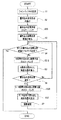
図1は、本発明の第1の実施形態に係わる画像処理装置の概略ブロック図である。画像処理装置は、カメラなどの撮像装置(図示せず)で撮像された被写体の画像(以下、入力画像と示す)に対し、電気的な処理を施して、レンズの歪曲収差など光学系で生じる歪みを補正する。
Hereinafter, embodiments will be described with reference to the drawings.
(First embodiment)
FIG. 1 is a schematic block diagram of an image processing apparatus according to the first embodiment of the present invention. An image processing device performs an electrical process on an image of a subject (hereinafter referred to as an input image) captured by an imaging device (not shown) such as a camera, and is generated in an optical system such as lens distortion. Correct distortion.
画像処理装置1は、ラインバッファ11と、書き込み画素位置計算部12と、読み出し画素位置計算部13と、書き込み画素位置判定部14と、パラメータ格納部15と、画素補間部16とから主に構成されている。
The
ラインバッファ11は、撮像装置からラスタスキャン順に読み込まれる入力画像の画素(入力画素)を、補正処理に必要なライン数だけ保持する。例えば、バイリニア補間を用いて歪曲収差の補正を行う場合、1〜2ライン分の画素を保持する。
The
第1の計算部としての書き込み画素位置計算部12は、補正対象である読み出し画素Piを用いて補間した画素が含まれると推定される、書き込み画素領域を算出する。具体的には、読み出し画素Piの位置(vo, ho)(以下、画素Pi(vo, ho)と示す)を含む、周辺4点の画素{Pi0(vo, ho)、Pi1(vo, ho-1)、Pi2(vo-1, ho-1)、Pi3(vo-1, ho)}からなる読み出し画素位置集合を定義する。なお、本説明において、画素位置座標(v, h)は、画像左上を原点(0, 0)として、vを垂直画素位置、hを水平画素位置としている。
The writing pixel
読み出し画素Pi0、Pi1、Pi2、Pi3のそれぞれについて、画素位置計算の関数を用い、対応する書き込み画素Po0、Po1、Po2、Po3の位置(vo’, ho’)、(vo’, ho-1’)、(vo-1’, ho-1’)、(vo-1’, ho’)を算出する。4点の画素Po0(vo’, ho’)、Po1(vo’, ho-1’)、Po2(vo-1’, ho-1’)、Po3(vo-1’, ho’)を頂点とする矩形領域が、書き込み画素領域となる。 For each of the read pixels Pi0, Pi1, Pi2, and Pi3, using the pixel position calculation function, the positions (vo ', ho'), (vo ', ho-1') of the corresponding write pixels Po0, Po1, Po2, Po3 are used. ), (Vo-1 ′, ho-1 ′), (vo-1 ′, ho ′). Four pixels Po0 (vo ', ho'), Po1 (vo ', ho-1'), Po2 (vo-1 ', ho-1'), Po3 (vo-1 ', ho') The rectangular area to be used becomes the writing pixel area.
画素位置計算には、例えば、多項式で表現される関数や、グリッドテーブル変換など、一般的な画素位置計算用の関数を用いることができる。ただし、画素位置計算関数は、逆関数が存在するものを用いる。 For the pixel position calculation, for example, a general function for pixel position calculation such as a function expressed by a polynomial or grid table conversion can be used. However, a pixel position calculation function having an inverse function is used.
第2の計算部としての読み出し画素位置計算部13は、書き込み画素領域内において、垂直位置、水平位置ともに整数となる画素の位置(書き込み画素候補Poc(v’, h’))を抽出する。そして、書き込み画素候補Poc(v’, h’)に対応する読み出し画素Pi(v”, h”)を、画素位置計算を行って算出する。なお、画素位置計算は、書き込み画素位置計算部12で行った画素位置計算の逆関数を用いて行う。候補が複数ある場合は、全ての候補Poc(v’, h’)に対して読み出し画素Pi(v”, h”)を算出する。
The read pixel
書き込み画素位置判定部14は、読み出し画素Pi(v”, h”)が集合に含まれている場合、当該画素Pi(v”, h”)に対する書き込み画素候補Poc(v’, h’)を、書き込み画素Po(v’, h’)として確定する。
When the read pixel Pi (v ″, h ″) is included in the set, the write pixel
パラメータ格納部15は、書き込み画素位置計算部12および読み出し画素位置計算部13における画素位置計算関数に用いるパラメータが格納されている。
The
画素補間部16は、確定した書き込み画素Po(v’, h’)に対応する読み出し画素Pi(v”, h”)の画素値を算出する。通常、読み出し画素Pi(v”, h”)の座標は非整数であるので、例えば周辺の4画素を用いたバイリニア補間など、既存の補間手法を用いて画素値を算出する。書き込み画素Po(v’, h’)の画素値として、算出した画素値を出力する。出力された画素値は、DRAMなどのメモリ(図示せず)に格納される。なお、出力画素は補正を行った順に出力するため、出力画素の位置はランダムとなる。
The
次に、画像処理装置1における画像補正処理の手順を説明する。図2は、第1の実施形態における画像補正処理を説明するフローチャートである。
Next, the procedure of image correction processing in the
まず、ラスタスキャン順に画像処理装置1に入力された画素を、ラインバッファ11に拡充する(S1)。ラインバッファ11には、画素補間部16での処理に必要なライン数分、入力画素を格納する。例えば、バイリニア補間を用いる場合、補間対象画素の周辺2×2画素(4画素)の画素値が必要となるため、少なくとも1ライン+1画素分の画素値を格納する。
First, the pixels input to the
次に、補正対象画素である読み出し画素Pi(vo, ho)を特定し、読み出し画素Piを用いて補間した画素が含まれると推定される、書き込み画素領域を算出する(S2)。具体的には、まず、読み出し画素Pi(vo, ho)を含む周囲4点の画素{Pi0(vo, ho)、Pi1(vo, ho-1)、Pi2(vo-1, ho-1)、Pi3(vo-1, ho)}からなる集合を定義する。すなわち、Pi1(vo, ho-1)は、Pi(vo, ho)の左隣の画素、Pi2(vo-1, ho-1)はPi(vo, ho)の左上の画素、Pi3(vo-1, ho)はPi(vo, ho)の上の画素である。次に、画素Pi0、Pi1、Pi2、Pi3のそれぞれについて、画素位置計算を行い、対応する書き込み画素Po0(vo’, ho’)、Po1(vo’, ho-1’)、Po2(vo-1’, ho-1’)、Po3(vo-1’, ho’)を算出する。 Next, a read pixel Pi (vo, ho) that is a correction target pixel is specified, and a write pixel region that is estimated to include a pixel interpolated using the read pixel Pi is calculated (S2). Specifically, first, four surrounding pixels including the readout pixel Pi (vo, ho) {Pi0 (vo, ho), Pi1 (vo, ho-1), Pi2 (vo-1, ho-1), Define a set consisting of Pi3 (vo-1, ho)}. That is, Pi1 (vo, ho-1) is a pixel adjacent to the left of Pi (vo, ho), Pi2 (vo-1, ho-1) is an upper left pixel of Pi (vo, ho), Pi3 (vo- 1, ho) is a pixel above Pi (vo, ho). Next, pixel positions are calculated for each of the pixels Pi0, Pi1, Pi2, and Pi3, and the corresponding writing pixels Po0 (vo ', ho'), Po1 (vo ', ho-1'), Po2 (vo-1 ', ho-1') and Po3 (vo-1 ', ho') are calculated.
画素位置計算は、例えば、多項式で表現される関数を用いる場合、次の手順で行う。 For example, when a function expressed by a polynomial is used, the pixel position calculation is performed according to the following procedure.
(a)像高の算出:入力画素の位置を、左上を原点とする(v, h)の座標系から、光学中心を原点とする(x, y)の座標系に変換する。なお、両座標系とも、水平方向は右側を正とし、垂直方向は下側を正とする。また、光学中心から入力画素までの距離(像高)rを算出する。以下に示す(1)〜(3)式を用いて行う。

(1)式において、vin は、垂直方向の入力画素位置(非負数)、[SENSOR_CROP_OFS_V]は、光学中心からの垂直画素位置オフセット(光学中心と、(v, h)座標系の原点との間の、垂直方向のオフセット)とする。また、(2)式において、hinは、水平方向の入力画素位置(非負数)、[SENSOR_CROP_OFS_H]は、光学中心からの水平画素位置オフセット(光学中心と、(v, h)座標系の原点との間の、水平方向のオフセット)とする。また、(3)式において、[NORM_SCALE]は正規化係数(非負数)とする。 In equation (1), v in is the vertical input pixel position (non-negative number), and [SENSOR_CROP_OFS_V] is the vertical pixel position offset from the optical center (optical center and the origin of the (v, h) coordinate system. Vertical offset between). In equation (2), h in is the horizontal input pixel position (non-negative number), and [SENSOR_CROP_OFS_H] is the horizontal pixel position offset from the optical center (optical center and the origin of the (v, h) coordinate system. In the horizontal direction). In the expression (3), [NORM_SCALE] is a normalization coefficient (non-negative number).
なお、画像中心と光学中心とが一致する場合、[SENSOR_CROP_OFS_V]、[SENSOR_CROP_OFS_H]は、以下の(4)(5)式となる。 When the image center coincides with the optical center, [SENSOR_CROP_OFS_V] and [SENSOR_CROP_OFS_H] are expressed by the following equations (4) and (5).
[SENSOR_CROP_OFS_V] = −(入力画像垂直サイズ/2 − 0.5) …(4)式
[SENSOR_CROP_OFS_ H] = −(入力画像水平サイズ/2 − 0.5) …(5)式
(b)画素位置計算の像高スケールの算出:光学中心から距離rにある点が、画素位置変換によって光学中心方向に移動する距離r_scaleを算出する。以下に示す(6)式を用いて行う。
[SENSOR_CROP_OFS_V] = − (input image vertical size / 2 − 0.5) (4) formula
[SENSOR_CROP_OFS_H] = − (input image horizontal size / 2−0.5) (5) Formula (b) Calculation of image height scale of pixel position calculation: The point at the distance r from the optical center is the optical center by pixel position conversion. The distance r_scale that moves in the direction is calculated. The following equation (6) is used.
r_scale = P0 + P1*r + P2 * r2 + P3*r3 + P4*r4 + P5*r5 + P6*r6 + P7*r7 + P8*r8 + P9*r9 + P10*r10 …(6)式
(6)式において、Px(x = 0〜10 )は、それぞれの次数に応じた多項式係数とする。
r_scale = P0 + P1 * r + P2 * r 2 + P3 * r 3 + P4 * r 4 + P5 * r 5 + P6 * r 6 + P7 * r 7 + P8 * r 8 + P9 * r 9 + P10 * r 10 (6) Equation (6) In equation (6), Px (x = 0 to 10) is a polynomial coefficient corresponding to each order.
(c)出力画素位置の算出:像高スケールを用いて入力画素位置を出力画素位置に変換し、(v, h)の座標系に戻す。以下に示す(7)(8)式を用いて行う。 (C) Calculation of output pixel position: The input pixel position is converted to the output pixel position using the image height scale, and the coordinate system is returned to the coordinate system of (v, h). This is performed using the following equations (7) and (8).
vout = r_scale * y − [SENSOR_CROP_OFS_V] …(7)式
hout = r_scale*x − [SENSOR_CROP_OFS_ H] …(8)式
(7)式において、voutは垂直方向の出力画素位置(非負数)、(8)式において、houtは水平方向の出力画素位置(非負数)とする。
v out = r_scale * y − [SENSOR_CROP_OFS_V] (7)
h out = r_scale * x-[SENSOR_CROP_OFS_H] (8) In equation (7), v out is the vertical output pixel position (non-negative number), and in equation (8), h out is the horizontal output pixel. Position (non-negative number).
すなわち、(a)から(c)の一連の手順により、読み出し画素Pi(vo, ho)、Pi1(vo, ho-1)、Pi2(vo-1, ho-1)、Pi3(vo-1, ho)が、それぞれ、書き込み画素Po0(vo’, ho’) 、Po1(vo’, ho-1’)、Po2(vo-1’, ho-1’)、Po3(vo-1’, ho’)に変換される。 That is, the readout pixels Pi (vo, ho), Pi1 (vo, ho-1), Pi2 (vo-1, ho-1), Pi3 (vo-1, -1) are performed by a series of steps (a) to (c). ho) are written pixels Po0 (vo ', ho'), Po1 (vo ', ho-1'), Po2 (vo-1 ', ho-1'), Po3 (vo-1 ', ho', respectively. ).
なお、画素位置計算として、上述のような多項式で表現される関数を用いる場合、[SENSOR_CROP_OFS_V]、[SENSOR_CROP_OFS_H]、[NORM_SCALE]、Px(x = 0〜10 )の各パラメータは予め設定されており、パラメータ格納部15に格納されているものとする。
In addition, when using the function expressed by the above polynomial for pixel position calculation, each parameter of [SENSOR_CROP_OFS_V], [SENSOR_CROP_OFS_H], [NORM_SCALE], and Px (x = 0 to 10) is set in advance. , And stored in the
画素位置計算は、グリッドテーブル変換を用いて行うこともできる。グリッドテーブルとは、画素位置(v, h)をグリッドノードとした2次元のアドレステーブルである。各グリッドノードには、変換先の画素位置が格納されている。グリッドノードの間に位置する任意の画素位置に対応するアドレスは、近傍グリッドノードから補間することで算出する。画素位置計算としてグリッドテーブル変換を用いる場合、次の手順で行う。 The pixel position calculation can also be performed using grid table conversion. The grid table is a two-dimensional address table with the pixel position (v, h) as a grid node. Each grid node stores the pixel position of the conversion destination. Addresses corresponding to arbitrary pixel positions located between grid nodes are calculated by interpolation from neighboring grid nodes. When grid table conversion is used for pixel position calculation, the following procedure is used.
(d)参照グリッドノードの算出:参照グリッドノードとして、入力画素の左上に位置するグリッドノードを決定する。以下に示す(9)(10)式を用いて行う。 (D) Calculation of reference grid node: The grid node located at the upper left of the input pixel is determined as the reference grid node. This is performed using the following equations (9) and (10).
ref_v = vin * GRID_PATCH_VSIZE_INV …(9)式
ref_h = hin * GRID_PATCH_HSIZE_INV …(10)式
(9)式において、vin は、垂直方向の入力画素位置(非負数)、GRID_PATCH_VSIZE_INVは、垂直グリッドノード間距離の逆数とする。GRID_PATCH_VSIZE_INVは、以下の(11)式を用いて算出する。
ref_h = h in * GRID_PATCH_HSIZE_INV (10) Equation (9) In equation (9), v in is the vertical input pixel position (non-negative number), and GRID_PATCH_VSIZE_INV is the reciprocal of the distance between vertical grid nodes. GRID_PATCH_VSIZE_INV is calculated using the following equation (11).
(11)式において、[SENSOR_CROP_VSIZE]は、入力画像垂直サイズ、[GRID_NODE_NUM_V]は、垂直グリッドノード数とする。 In equation (11), [SENSOR_CROP_VSIZE] is the input image vertical size, and [GRID_NODE_NUM_V] is the number of vertical grid nodes.
また、(10)式において、hinは、水平方向の入力画素位置(非負数)、GRID_PATCH_HSIZE_INVは、水平グリッドノード間距離の逆数とする。GRID_PATCH_HSIZE_INVは、以下の(12)式を用いて算出する。
(12)式において、[SENSOR_CROP_HSIZE]は、入力画像水平サイズ、[GRID_NODE_NUM_H]は、水平グリッドノード数とする。 In equation (12), [SENSOR_CROP_HSIZE] is the horizontal size of the input image, and [GRID_NODE_NUM_H] is the number of horizontal grid nodes.
(e)重みの算出:入力画素位置から参照グリッドノードを含む周囲4点のグリッドノードに対する、垂直方向及び水平方向の距離の比に基づく重みを算出する。以下に示す(13)(14)式を用いて算出する。 (E) Calculation of weight: A weight is calculated based on a ratio of vertical and horizontal distances from the input pixel position to four surrounding grid nodes including the reference grid node. It calculates using the following (13) (14) Formula.
weight_v = ref_v − [ref_v] …(13)式
weight_h = ref_h − [ref_h] …(14)式
(13)(14)式において、[]はガウス記号を表す。参照グリッドノードに関する垂直方向の重みは1−weight_vとなる。また、参照グリッドノードに関する水平方向の重みは、1−weight_hとなる。
weight_v = ref_v − [ref_v] (13)
weight_h = ref_h− [ref_h] (14) Expression (13) In Expression (14), [] represents a Gaussian symbol. The vertical weight for the reference grid node is 1−weight_v. Also, the horizontal weight for the reference grid node is 1-weight_h.
(f)出力画素位置の算出:参照グリッドノードを含む周囲4点のグリッドノードのテーブルと、入力画素位置に対する各グリッドノードの重みを用い、バイリニア補間によって、出力画素位置を算出する。 (F) Calculation of output pixel position: The output pixel position is calculated by bilinear interpolation using a table of four surrounding grid nodes including the reference grid node and the weight of each grid node with respect to the input pixel position.
(f−1)垂直方向の出力画素位置の算出
以下に示す(15)〜(17)式を用いて算出する。
(F-1) Calculation of Output Pixel Position in Vertical Direction Calculation is performed using the following equations (15) to (17).
v0out = table_v(ref_v, ref_h) * (1−weight_h) + table_v(ref_v, ref_h+1) * weight_h
…(15)式
v1out = table_v(ref_v+1, ref_h) * (1−weight_h) + table_v(ref_v+1, ref_h+1) * weight_h
…(16)式
vout = v0out * (1−weight_v) + v1out * weight_v …(17)式
(15)(16)式において、table_v(v, h)は、垂直画素位置グリッドテーブルとする。また、(17)式において、voutは、は垂直方向の出力画素位置(非負数)である。
v0 out = table_v (ref_v, ref_h) * (1−weight_h) + table_v (ref_v, ref_h + 1) * weight_h
... (15) Formula
v1 out = table_v (ref_v + 1, ref_h) * (1−weight_h) + table_v (ref_v + 1, ref_h + 1) * weight_h
... (16) Formula
v In out = v0 out * (1- weight_v) + v1 out * weight_v ... (17) Equation (15) (16), Table_v (v, h) is the vertical pixel position grid table. In Expression (17), v out is an output pixel position (non-negative number) in the vertical direction.
(f−2)水平方向の出力画素位置の算出
以下に示す(18)〜(20)式を用いて算出する。
(F-2) Calculation of output pixel position in horizontal direction Calculation is performed using the following equations (18) to (20).
h0out = table_ h (ref_v, ref_h) * (1−weight_h) + table_ h (ref_v, ref_h+1) * weight_h
…(18)式
h1out = table_h(ref_v+1, ref_h) * (1−weight_h)
+ table_h(ref_v+1, ref_h+1) * weight_h …(19)式
hout = h0out * (1−weight_h) + h1out * weight_v …(20)式
(18)(19)式において、table_h(v, h)は、水平画素位置グリッドテーブルとする。また、(20)式において、houtは、は水平方向の出力画素位置(非負数)である。
h0 out = table_ h (ref_v, ref_h) * (1−weight_h) + table_ h (ref_v, ref_h + 1) * weight_h
... (18) Formula
h1 out = table_h (ref_v + 1, ref_h) * (1−weight_h)
+ table_h (ref_v + 1, ref_h + 1) * weight_h (19)
In h out = h0 out * (1 -weight_h) + h1 out * weight_v ... (20) Equation (18) (19), table_h (v, h) is the horizontal pixel position grid table. In Expression (20), h out is the horizontal output pixel position (non-negative number).
すなわち、(d)から(f)の一連の手順により、読み出し画素Pi(vo, ho)、Pi1(vo, ho-1)、Pi2(vo-1, ho-1)、Pi3(vo-1, ho)が、それぞれ、書き込み画素Po0(vo’, ho’) 、Po1(vo’, ho-1’)、Po2(vo-1’, ho-1’)、Po3(vo-1’, ho’)に変換される。 That is, the readout pixels Pi (vo, ho), Pi1 (vo, ho-1), Pi2 (vo-1, ho-1), Pi3 (vo-1, 1) are performed by a series of steps (d) to (f). ho) are written pixels Po0 (vo ', ho'), Po1 (vo ', ho-1'), Po2 (vo-1 ', ho-1'), Po3 (vo-1 ', ho', respectively. ).
なお、画素位置計算として、上述のようなグリッドテーブル変換を用いる場合、[SENSOR_CROP_VSIZE]、[GRID_NODE_NUM_V]、[SENSOR_CROP_HSIZE]、[GRID_NODE_NUM_H]、table_v(v, h)、table_h(v, h)の各パラメータは予め設定されており、パラメータ格納部15に格納されているものとする。
When the above grid table conversion is used for pixel position calculation, each parameter of [SENSOR_CROP_VSIZE], [GRID_NODE_NUM_V], [SENSOR_CROP_HSIZE], [GRID_NODE_NUM_H], table_v (v, h), table_h (v, h) Are set in advance and are stored in the
画素位置計算により算出された、4点の画素Po0(vo’, ho’) 、Po1(vo’, ho-1’)、Po2(vo-1’, ho-1’)、Po3(vo-1’, ho’)を頂点とする矩形領域が、書き込み画素領域として特定される。 The four pixels Po0 (vo ', ho'), Po1 (vo ', ho-1'), Po2 (vo-1 ', ho-1'), Po3 (vo-1) calculated by the pixel position calculation A rectangular area whose apex is ', ho') is specified as the writing pixel area.
次に、上記特定された矩形領域内において、垂直座標、及び、水平座標が共に整数となる画素位置(書き込み画素候補Poc(v’, h’))を抽出する。例えば、画素Po0(vo’, ho’) 、Po1(vo’, ho-1’)、Po2(vo-1’, ho-1’)、Po3(vo-1’, ho’)の各座標を、繰り上げ・繰り下げにより調整・整数化し、得られた画素位置に外接する矩形領域内のすべての画素位置を、書き込み画素候補Poc(v’, h’)とする(S3)。繰り上げ・繰り下げによる調整・整数化は、以下に示す(21)(22)式を用いて行う。なお、4点のうち、左側または上側に位置する画素については、(21)式を用い、右側または下側に位置する画素については、(22)式を用いる。 Next, a pixel position (write pixel candidate Poc (v ′, h ′)) in which the vertical coordinate and the horizontal coordinate are both integers is extracted in the specified rectangular area. For example, the coordinates of pixels Po0 (vo ', ho'), Po1 (vo ', ho-1'), Po2 (vo-1 ', ho-1'), Po3 (vo-1 ', ho') Then, adjustment and integerization are carried out by carry-up and carry-down, and all pixel positions in the rectangular area circumscribing the obtained pixel position are set as write pixel candidates Poc (v ′, h ′) (S3). Adjustment and integerization by carry-up and carry-down are performed using the following equations (21) and (22). Of the four points, Expression (21) is used for the pixel located on the left side or the upper side, and Expression (22) is used for the pixel located on the right side or the lower side.
調整後画素位置 = [書き込み画素位置 − WRITE_AREA_DELTA] …(21)式
調整後画素位置 = [書き込み画素位置 + WRITE_AREA_DELTA] …(22)式
(21)(22)式において、WRITE_AREA_DELTAは整数化調整値であり、予め設定された値である。また、[]はガウス記号を表す。
Adjusted pixel position = [Write pixel position − WRITE_AREA_DELTA] (21) Expression Adjusted pixel position = [Write pixel position + WRITE_AREA_DELTA] (22) Expression (21) In Expression (21), WRITE_AREA_DELTA is an integer adjustment value. Yes, it is a preset value. [] Represents a Gaussian symbol.
続いて、S3で求めたすべての書き込み画素候補Poc(v’, h’)に対し、書き込み画素Po(v’, h’)であるか否かの判定を行う。判定をまだ行っていない書き込み画素候補Poc(v’, h’)がある場合(S4、No)、画素位置計算により、対応する読み出し画素Pi(v”, h”)を算出する(S5)。画素位置計算は、S2で用いた画素位置計算の逆関数を用いて行う。このとき、Pi(v”, h”)の垂直座標、水平座標は、非整数となる。 Subsequently, it is determined whether or not all the write pixel candidates Poc (v ′, h ′) obtained in S <b> 3 are write pixels Po (v ′, h ′). When there is a writing pixel candidate Poc (v ′, h ′) that has not been determined yet (S4, No), the corresponding readout pixel Pi (v ″, h ″) is calculated by pixel position calculation (S5). The pixel position calculation is performed using an inverse function of the pixel position calculation used in S2. At this time, the vertical and horizontal coordinates of Pi (v ″, h ″) are non-integer numbers.
次に、Pi(v”, h”)の画素値を補間によって算出するために必要な画素を特定する。例えば、バイリニア補間によって画素値を算出する場合、Pi(v”, h”)の周囲4点の画素が補間に必要な画素となる。補間に必要なすべての画素が、集合に含まれている場合、当該読み出し画素Pi(v”, h”)に対応する書き込み画素候補Poc(v’, h’)を、書き込み画素Po(v’, h’)と確定する(S6、Yes)。 Next, a pixel necessary for calculating the pixel value of Pi (v ″, h ″) by interpolation is specified. For example, when pixel values are calculated by bilinear interpolation, four pixels around Pi (v ″, h ″) are pixels necessary for interpolation. When all the pixels necessary for the interpolation are included in the set, the write pixel candidate Poc (v ′, h ′) corresponding to the read pixel Pi (v ″, h ″) is set as the write pixel Po (v ′ , h ′) (S6, Yes).
この場合、確定した書き込み画素Po(v’, h’)の画素値を、対応する読み出し画素Pi(v”, h”)の画素値を画素補間によって算出して出力する(S7)。なお、出力画素Po(v’, h’)は、ラスタスキャン順でなくランダムとなる。続いてS4に戻り、未判定の書き込み画素候補Poc(v’, h’)の有無を調べる。 In this case, the pixel value of the determined write pixel Po (v ′, h ′) is calculated by calculating the pixel value of the corresponding read pixel Pi (v ″, h ″) by pixel interpolation (S7). Note that the output pixel Po (v ′, h ′) is random, not the raster scan order. Subsequently, the process returns to S4 to check whether there is an undetermined write pixel candidate Poc (v ′, h ′).
一方、補間に必要な画素のうち、集合に含まれていない画素が存在する場合、当該読み出し画素Pi(v”, h”)に対応する書き込み画素候補Poc(v’, h’)は、書き込み画素Po(v’, h’)でないと確定する(S6、No)。この場合、画素補間は行わずに、S4に戻って、未判定の書き込み画素候補Poc(v’, h’)の有無を調べる。 On the other hand, if there is a pixel that is not included in the set among the pixels necessary for interpolation, the write pixel candidate Poc (v ′, h ′) corresponding to the read pixel Pi (v ″, h ″) is written. It is determined that the pixel is not Po (v ′, h ′) (S6, No). In this case, pixel interpolation is not performed, and the process returns to S4 to check whether there is an undetermined write pixel candidate Poc (v ′, h ′).
S4において、S3で求めたすべての書き込み画素候補Poc(v’, h’)について、判定が行われている場合、画像補正処理の一連の手順を終了する。 If it is determined in S4 that all the write pixel candidates Poc (v ′, h ′) obtained in S3 have been determined, a series of procedures for image correction processing are terminated.
このように、本実施形態によれば、撮像装置からラスタスキャン順に読み込まれる入力画素を、この順に補正処理を行う。従って、補正に必要な入力画素の範囲を1乃至数ライン程度で抑えることができるため、入力画素を格納するラインバッファ11の搭載量を低減することができ、製造コストを抑制することができる。
As described above, according to the present embodiment, the input pixels read from the imaging device in the raster scan order are corrected in this order. Therefore, since the input pixel range necessary for correction can be suppressed to about one to several lines, the mounting amount of the
なお、ラインバッファ11の搭載量は、画素補間の手法に応じて設定される。例えば、バイリニア法を用いる場合、2ライン程度搭載すればよいが、バイキュービック法を用いる場合、4ライン程度搭載する必要がある。
The amount of
また、読み出し画素から書き込み画素を算出する画素位置計算の方法は、上述の方法に限定されない。すなわち、逆関数が存在する方法であれば、任意の方法を用いることができる。また、複数の画素位置計算方法を組み合わせて用いてもよい。
(第2の実施形態)
第1の実施形態の画像処理装置では、レンズの歪曲収差の補正や単色の入力画像の補正を行っていた。これに対し、第2の実施形態においては、R、B、Gの3チャネルの色画像について、倍率色収差補正を行う点が異なっている。第2の実施形態の画像処理装置は、第1の実施形態と同様の構成である。以下、画像補正処理方法について説明する。なお、同じ構成要素や同じ処理については、同じ符号を付して説明を省略する。
Further, the pixel position calculation method for calculating the write pixel from the read pixel is not limited to the above-described method. That is, any method can be used as long as an inverse function exists. A plurality of pixel position calculation methods may be used in combination.
(Second Embodiment)
In the image processing apparatus according to the first embodiment, correction of distortion of a lens and correction of a monochromatic input image are performed. On the other hand, the second embodiment is different in that magnification chromatic aberration correction is performed for color images of three channels of R, B, and G. The image processing apparatus according to the second embodiment has the same configuration as that of the first embodiment. Hereinafter, the image correction processing method will be described. In addition, about the same component and the same process, the same code | symbol is attached | subjected and description is abbreviate | omitted.
図3は、第2の実施形態における画像補正処理を説明するフローチャートである。G,B、Rのそれぞれの色画素について、入力画素をラインバッファ11に拡充する(S1)。まず、G画素の補正対象入力画素Pi_g(vo_g, ho_g)に関する読み出し画素位置集合を算出する。この集合について、周知の画素位置計算方法を適用することにより、書き込み画素領域を特定し(S2)、書き込み画素候補Poc(v’, h’)を抽出する(S3)。そして、S2で用いた画素位置計算の逆関数を用いて、G画素の読み出し画素Pi_g(vg”, hg”)を算出する(S51)。 FIG. 3 is a flowchart illustrating image correction processing according to the second embodiment. For each color pixel of G, B, and R, the input pixels are expanded in the line buffer 11 (S1). First, a readout pixel position set relating to the correction target input pixel Pi_g (vo_g, ho_g) of the G pixel is calculated. A known pixel position calculation method is applied to this set to identify a writing pixel region (S2), and a writing pixel candidate Poc (v ′, h ′) is extracted (S3). Then, the readout pixel Pi_g (vg ″, hg ″) of the G pixel is calculated using the inverse function of the pixel position calculation used in S2 (S51).
読み出し画素Pi_g(vg”, hg”)の画素値を補間により算出するために必要なすべての画素が、集合に含まれている場合、当該読み出し画素Pi_g(vg”, hg”)に対応する書き込み画素候補Poc(v’, h’)を、書き込み画素Po(v’, h’)と確定する(S6、Yes)。 When all the pixels necessary for calculating the pixel value of the readout pixel Pi_g (vg ″, hg ″) by interpolation are included in the set, the writing corresponding to the readout pixel Pi_g (vg ″, hg ″) The pixel candidate Poc (v ′, h ′) is determined as the writing pixel Po (v ′, h ′) (S6, Yes).
続いて、周知の画素位置計算方法を適用することにより、G画素の読み出し画素Pi_g(vg”, hg”)からB、R画素の読み出し画素Pi_b(vb”, hb”)、Pi_r(vr”, hr”)をそれぞれ特定する(S52)。なお、画素位置計算に用いるパラメータは、G画素からB画素を算出する際に用いるものと、G画素からR画素を算出する際に用いるものが、それぞれ予め設定されている。 Subsequently, by applying a known pixel position calculation method, the readout pixels Pi_g (vg ″, hg ″) of the G pixel to the readout pixels Pi_b (vb ″, hb ″) of the B and R pixels, Pi_r (vr ″, hr ") is specified (S52). Note that parameters used for calculating the pixel position are preset for parameters used when calculating the B pixel from the G pixel and parameters used when calculating the R pixel from the G pixel.
最後に、Pi_g(vg”, hg”)、Pi_b(vb”, hb”)、Pi_r(vr”, hr”)のそれぞれについて、画素補間を行って画素値を算出し、書き込み画素Po(v’, h’)における画素値として出力する(S7)。すべての書き込み画素候補Poc(v’, h’)について、確定判定と画素補間による画素値算出が終了したら、一連の画素補正処理を終了する。 Finally, for each of Pi_g (vg ", hg"), Pi_b (vb ", hb"), Pi_r (vr ", hr"), pixel interpolation is performed to calculate the pixel value, and the writing pixel Po (v ' , h ′) as a pixel value (S7). When the pixel value calculation by the final determination and the pixel interpolation is completed for all the write pixel candidates Poc (v ′, h ′), a series of pixel correction processing is ended.
このように、本実施形態によれば、R、B、Gの3チャネルの色画像について、倍率色収差補正を行う際にも、撮像装置からラスタスキャン順に読み込まれる入力画素を、この順に補正処理を行う。従って、補正に必要な入力画素の範囲を数ライン程度で抑えることができるため、入力画素を格納するラインバッファ11の搭載量を低減することができ、製造コストを抑制することができる。
As described above, according to the present embodiment, when correcting chromatic aberration of magnification for three color images of R, B, and G, the input pixels read from the imaging device in the raster scan order are corrected in this order. Do. Therefore, since the input pixel range necessary for correction can be suppressed to about several lines, the amount of the
なお、上述では、B、R画素の読み出し画素Pi_b(vb”, hb”)、Pi_r(vr”, hr”)は、G画素の読み出し画素Pi_g(vg”, hg”)から画素位置計算を用いて算出しているが、書き込み画素Po(v’, h’)から画素位置計算を用いて算出してもよい。 In the above description, the readout pixels Pi_b (vb ″, hb ″) and Pi_r (vr ″, hr ″) of the B and R pixels use pixel position calculation from the readout pixel Pi_g (vg ″, hg ″) of the G pixel. However, the pixel position calculation may be performed from the writing pixel Po (v ′, h ′).
また、画素位置計算の方法は、逆関数が存在する方法であれば、任意の方法を用いることができる。更に、複数の画素位置計算方法を組み合わせて用いてもよい。例えば、多項式を用いた関数でレンズの歪曲収差の補正を行った後、グリッドテーブル変換を用いて色倍率収差の補正を行うなど、複数の補正を行うことが可能になる。
(第3の実施形態)
第1の実施形態の画像処理装置では、入力画像に対してレンズの歪曲収差の補正を行い、歪みを補正した画像を出力していた。これに対し、第3の実施形態においては、歪み補正処理時にピラミッド処理も行い、ピラミッド画像(解像度の異なる同一画像の集合)も生成する点が異なっている。
As a method for calculating the pixel position, any method can be used as long as an inverse function exists. Further, a plurality of pixel position calculation methods may be used in combination. For example, it is possible to perform a plurality of corrections such as correcting lens distortion using a function using a polynomial and then correcting chromatic magnification aberration using grid table conversion.
(Third embodiment)
In the image processing apparatus according to the first embodiment, the distortion of the lens is corrected for the input image, and an image in which the distortion is corrected is output. In contrast, the third embodiment is different in that pyramid processing is also performed during distortion correction processing, and pyramid images (a set of identical images with different resolutions) are also generated.
図4は、第3の実施形態に係わる画像処理装置の概略ブロック図である。なお、第1の実施形態の画像処理装置と同じ構成要素については、同じ符号を付して説明を省略する。 FIG. 4 is a schematic block diagram of an image processing apparatus according to the third embodiment. Note that the same components as those in the image processing apparatus according to the first embodiment are denoted by the same reference numerals and description thereof is omitted.
書き込み画素位置スケール部12aは、補正対象である読み出し画素Piを用いて補間した画素に、所定のスケールを乗じてピラミッド処理を施した画素が含まれると推定される、書き込み画素領域を算出する。具体的には、書き込み画素位置計算部12において算出された、書き込み画素領域の頂点の画素Po0(vo’, ho’)、Po1(vo’, ho-1’)、Po2(vo-1’, ho-1’)、Po3(vo-1’, ho’)のそれぞれについて、所定のピラミッド画像を生成するためのスケールを乗ずる。これにより、ピラミッド画像における書き込み画素領域の頂点の画素Po0(vo_s’, ho_s’)、Po1(vo_s’, ho-1_s’)、Po2(vo-1_s’, ho-1_s’)、Po3(vo-1_s’, ho_s’)を算出する。
The writing pixel
読み出し画素位置スケール部13aは、書き込み画素位置スケール部12aで算出した、ピラミッド画像の書き込み画素領域内において、垂直位置、水平位置ともに整数となる画素の位置(書き込み画素候補Poc(v_s’, h_s’))を抽出する。そして、所定のスケールの逆数を乗じ、等倍の出力画像における書き込み画素位置に変換する。書き込み画素候補Poc(v_s’, h_s’)に対応する読み出し画素Pi(v_s”, h_s”)を、画素位置計算を行って算出する。なお、画素位置計算は、書き込み画素位置計算部12で行った画素位置計算の逆関数を用いて行う。候補が複数ある場合は、全ての候補Poc(v_s’, h_s’)に対して読み出し画素Pi(v_s”, h_s”)を算出する。
The read pixel
パラメータ格納部15´は、書き込み画素位置計算部12および読み出し画素位置計算部13における画素位置計算関数に用いるパラメータ加え、生成するピラミッド画像のスケールが格納されている。なお、複数のスケールのピラミッド画像を生成する場合、それぞれの画像に対応する複数のスケールが格納されている。
The
次に、本実施形態における画像処理方法について説明する。図5は、第3の実施形態における画像補正処理を説明するフローチャートである。なお、第1の実施形態の画像処理方法と同じ処理については、同じ符号を付して説明を省略する。 Next, an image processing method in the present embodiment will be described. FIG. 5 is a flowchart for explaining image correction processing in the third embodiment. Note that the same processes as those of the image processing method of the first embodiment are denoted by the same reference numerals and description thereof is omitted.
まず、ラスタスキャン順に画像処理装置1´に入力された画素を、ラインバッファ11に拡充する(S1)。次に、補正対象画素である読み出し画素Pi(vo, ho)を特定し、読み出し画素Piを用いて補間した画素が含まれると推定される、書き込み画素領域を算出する(S2)。画素位置計算は、多項式で表現される関数を用いてもよいし、グリッドテーブル変換を用いてもよい。また、多項式で表現される関数を用いて計算した結果に対してグリッドテーブル変換を更に用いてもよいし、グリッドテーブル変換により計算した結果に対して多項式で表現される関数を更に用いてもよい。
First, the pixels input to the
次に、所定のスケールのピラミッド画像に対応する書き込み画素領域を算出する(S20)。画素位置計算に多項式で表現される関数を用いる場合、S2において算出された画素位置計算の像高スケール(r_scale)を用い、ピラミッド画像のスケールに応じて当該像高スケールを再スケールする。具体的には、以下に示す(23)式を用いて行う。 Next, a writing pixel area corresponding to a pyramid image of a predetermined scale is calculated (S20). When a function expressed by a polynomial is used for pixel position calculation, the image height scale (r_scale) of pixel position calculation calculated in S2 is used, and the image height scale is rescaled according to the scale of the pyramid image. Specifically, the following equation (23) is used.
r_scale_scaled = r_scale * scale …(23)式
(23)式において、scaleは、通常の歪み補正のみを行う出力画像に対するピラミッド画像のスケール値である。また、scaleの値は予め設定されており、パラメータ格納部15´に格納されているものとする。通常、scaleの値は、0.5〜2程度の値が設定されている。
r_scale_scaled = r_scale * scale (23) In equation (23), scale is the scale value of the pyramid image with respect to the output image for which only normal distortion correction is performed. In addition, the value of scale is set in advance and is stored in the
続いて、ピラミッド画像用にスケールされた像高スケールを、(7)(8)式を用いて(v, h)の座標系に戻す。ただし、(7)(8)式において、r_scaleにはr_scale_scaledを代入する。このようにして、読み出し画素Pi(vo, ho)、Pi1(vo, ho-1)、Pi2(vo-1, ho-1)、Pi3(vo-1, ho)が、それぞれ、書き込み画素Po0(vo_s’, ho_s’)、Po1(vo_s’, ho-1_s’)、Po2(vo-1_s’, ho-1_s’)、Po3(vo-1_s’, ho_s’)に変換される。 Subsequently, the image height scale scaled for the pyramid image is returned to the coordinate system of (v, h) using equations (7) and (8). However, in the equations (7) and (8), r_scale_scaled is substituted for r_scale. In this way, the readout pixels Pi (vo, ho), Pi1 (vo, ho-1), Pi2 (vo-1, ho-1), and Pi3 (vo-1, ho) are respectively written to the writing pixel Po0 ( vo_s ′, ho_s ′), Po1 (vo_s ′, ho-1_s ′), Po2 (vo-1_s ′, ho-1_s ′), and Po3 (vo-1_s ′, ho_s ′).
グリッドテーブル変換を用いて画素位置計算を行う場合、S2において算出された、書き込み画素Po0(vo’, ho’) 、Po1(vo’, ho-1’)、Po2(vo-1’, ho-1’)、Po3(vo-1’, ho’)について、水平方向の座標位置、及び、垂直方向の座標位置にピラミッド画像のスケールを乗ずる。具体的には、まず、(24)(25)式を用い、書き込み画素の位置を、左上を原点とする(v, h)の座標系から、光学中心を原点とする(x, y)の座標系に変換する。 When pixel position calculation is performed using grid table conversion, the write pixels Po0 (vo ', ho'), Po1 (vo ', ho-1'), Po2 (vo-1 ', ho-) calculated in S2 are calculated. 1 ′) and Po3 (vo-1 ′, ho ′), the horizontal coordinate position and the vertical coordinate position are multiplied by the scale of the pyramid image. Specifically, first, using the formulas (24) and (25), the position of the writing pixel is determined from the coordinate system of (v, h) with the upper left as the origin and (x, y) with the optical center as the origin. Convert to coordinate system.
x = hout + [SENSOR_CROP_OFS_ H] …(24)式
y = vout + [SENSOR_CROP_OFS_ V] …(25)式
変換後の座標位置に対し、ピラミッド画像のスケールを用いて再スケールする。具体的には、以下の(26)(27)式を用いて行う。
x = h out + [SENSOR_CROP_OFS_ H] (24) formula
y = v out + [SENSOR_CROP_OFS_ V ] ... (25) coordinate position after expression convert to, rescaling using a scale of pyramid images. Specifically, the following equations (26) and (27) are used.
x_scaled = x * scale …(26)式
y_scaled = y * scale …(27)式
最後に、ピラミッド画像用にスケールされた座標位置を、左上を原点とする(v, h)の座標系に戻す。このようにして、読み出し画素Pi(vo, ho)、Pi1(vo, ho-1)、Pi2(vo-1, ho-1)、Pi3(vo-1, ho)が、それぞれ、書き込み画素Po0(vo_s’, ho_s’)、Po1(vo_s’, ho-1_s’)、Po2(vo-1_s’, ho-1_s’)、Po3(vo-1_s’, ho_s’)に変換される。
x_scaled = x * scale (26)
y_scaled = y * scale (27) Finally, the coordinate position scaled for the pyramid image is returned to the coordinate system of (v, h) with the upper left as the origin. In this way, the readout pixels Pi (vo, ho), Pi1 (vo, ho-1), Pi2 (vo-1, ho-1), and Pi3 (vo-1, ho) are respectively written to the writing pixel Po0 ( vo_s ′, ho_s ′), Po1 (vo_s ′, ho-1_s ′), Po2 (vo-1_s ′, ho-1_s ′), and Po3 (vo-1_s ′, ho_s ′).
すなわち、画素位置計算として、多項式で表現される関数を用いる場合にも、グリッドテーブル変換を用いる場合にも、S2の計算結果や途中経過を用い、4点の画素Po0(vo_s’, ho_s’)、Po1(vo_s’, ho-1_s’)、Po2(vo-1_s’, ho-1_s’)、Po3(vo-1_s’, ho_s’)を頂点とする矩形領域が、ピラミッド画像の書き込み画素領域を特定することができる。 In other words, the pixel position calculation uses the calculation result of S2 and the progress in the middle, whether using a function expressed by a polynomial or grid table conversion, and the four-point pixel Po0 (vo_s ′, ho_s ′). , Po1 (vo_s ', ho-1_s'), Po2 (vo-1_s ', ho-1_s'), Po3 (vo-1_s ', ho_s'), the rectangular area is the writing pixel area of the pyramid image Can be identified.
なお、複数のスケールのピラミッド画像を生成する場合、S20を繰り返し実行し、それぞれのスケールに対応する書き込み画素領域を特定する。 When generating a plurality of scale pyramid images, S20 is repeatedly executed to specify a writing pixel region corresponding to each scale.
次に、S2、及びS20を実行することによって特定された各矩形領域(書き込み画素領域)内において、垂直座標、及び、水平座標が共に整数となる画素位置(書き込み画素候補Poc(v’, h’))を抽出する(S3)。続いて、S3で求めたすべての書き込み画素候補Poc(v’, h’)に対し、書き込み画素Po(v’, h’)であるか否かの判定を行う。判定をまだ行っていない書き込み画素候補Poc(v’, h’)がある場合(S4、No)、画素位置計算により、対応する読み出し画素Pi(v”, h”)を算出する(S5)。なお、S5では、S2において特定された書き込み画素領域に対応する書き込み画素候補について、対応する読み出し画素を算出する。 Next, in each rectangular area (write pixel area) identified by executing S2 and S20, the pixel position (write pixel candidate Poc (v ′, h) where both the vertical coordinate and the horizontal coordinate are integers. ')) Is extracted (S3). Subsequently, it is determined whether or not all the write pixel candidates Poc (v ′, h ′) obtained in S <b> 3 are write pixels Po (v ′, h ′). When there is a writing pixel candidate Poc (v ′, h ′) that has not been determined yet (S4, No), the corresponding readout pixel Pi (v ″, h ″) is calculated by pixel position calculation (S5). In S5, a corresponding read pixel is calculated for the write pixel candidate corresponding to the write pixel area specified in S2.
なお、S20において特定された、ピラミッド画像用にスケールされた書き込み画素領域に対応する書き込み画素候補Poc(v’, h’)については、S5において画素位置計算を行う前に、書き込み画素候補に対してS20において用いたスケールの逆数を乗じ、等倍の出力画像における書き込み画素位置に変換する(S50)。次に、変換した画素位置に対し、S20で用いた画素位置計算の逆関数を用いて読み出し画素の画素位置計算を行う(S5)。なお、S5において算出した、Pi(v”, h”)の垂直座標、水平座標は、非整数となる。 Note that the writing pixel candidate Poc (v ′, h ′) corresponding to the writing pixel area scaled for the pyramid image specified in S20 is determined with respect to the writing pixel candidate before the pixel position calculation in S5. Then, it is multiplied by the inverse of the scale used in S20 and converted into the writing pixel position in the output image of the same magnification (S50). Next, the pixel position of the readout pixel is calculated for the converted pixel position using the inverse function of the pixel position calculation used in S20 (S5). Note that the vertical and horizontal coordinates of Pi (v ″, h ″) calculated in S5 are non-integer numbers.
次に、Pi(v”, h”)の画素値を補間によって算出するために必要な画素を特定する。例えば、バイリニア補間によって画素値を算出する場合、Pi(v”, h”)の周囲4点の画素が補間に必要な画素となる。補間に必要なすべての画素が、集合に含まれている場合、当該読み出し画素Pi(v”, h”)に対応する書き込み画素候補Poc(v’, h’)を、書き込み画素Po(v’, h’)と確定する(S6、Yes)。 Next, a pixel necessary for calculating the pixel value of Pi (v ″, h ″) by interpolation is specified. For example, when pixel values are calculated by bilinear interpolation, four pixels around Pi (v ″, h ″) are pixels necessary for interpolation. When all the pixels necessary for the interpolation are included in the set, the write pixel candidate Poc (v ′, h ′) corresponding to the read pixel Pi (v ″, h ″) is set as the write pixel Po (v ′ , h ′) (S6, Yes).
この場合、確定した書き込み画素Po(v’, h’)の画素値を、対応する読み出し画素Pi(v”, h”)の画素値を画素補間によって算出して出力する(S7)。なお、出力画素Po(v’, h’)は、ラスタスキャン順でなくランダムとなる。続いてS4に戻り、未判定の書き込み画素候補Poc(v’, h’)の有無を調べる。 In this case, the pixel value of the determined write pixel Po (v ′, h ′) is calculated by calculating the pixel value of the corresponding read pixel Pi (v ″, h ″) by pixel interpolation (S7). Note that the output pixel Po (v ′, h ′) is random, not the raster scan order. Subsequently, the process returns to S4 to check whether there is an undetermined write pixel candidate Poc (v ′, h ′).
一方、補間に必要な画素のうち、集合に含まれていない画素が存在する場合、当該読み出し画素Pi(v”, h”)に対応する書き込み画素候補Poc(v’, h’)は、書き込み画素Po(v’, h’)でないと確定する(S6、No)。この場合、画素補間は行わずに、S4に戻って、未判定の書き込み画素候補Poc(v’, h’)の有無を調べる。 On the other hand, if there is a pixel that is not included in the set among the pixels necessary for interpolation, the write pixel candidate Poc (v ′, h ′) corresponding to the read pixel Pi (v ″, h ″) is written. It is determined that the pixel is not Po (v ′, h ′) (S6, No). In this case, pixel interpolation is not performed, and the process returns to S4 to check whether there is an undetermined write pixel candidate Poc (v ′, h ′).
S4において、S3で求めたすべての書き込み画素候補Poc(v’, h’)について、判定が行われている場合、画像補正処理の一連の手順を終了する。 If it is determined in S4 that all the write pixel candidates Poc (v ′, h ′) obtained in S3 have been determined, a series of procedures for image correction processing are terminated.
なお、S2において、歪み補正処理を施した等倍の出力画像における書き込み画素領域を算出後、ピラミッド画像の各スケールの手順は依存関係がないため、算出順序の並び替えや、並列実行が可能である。例えば、複数のスケールのピラミッド画像を生成する場合、S20とS50については、どちらのスケールを先に実施してもよい。また、等倍の出力画像を生成した後、S2の算出結果を用いてスケール画像を生成してもよい。 In S2, after calculating the writing pixel area in the output image having the same magnification subjected to the distortion correction processing, the procedure of each scale of the pyramid image has no dependency, so that the calculation order can be rearranged and executed in parallel. is there. For example, when generating a pyramid image of a plurality of scales, either scale may be implemented first for S20 and S50. In addition, after generating an output image of the same size, a scale image may be generated using the calculation result of S2.
このように、本実施形態によれば、撮像装置からラスタスキャン順に読み込まれる入力画素を、この順に補正処理を行う。従って、補正に必要な入力画素の範囲を1乃至数ライン程度で抑えることができるため、入力画素を格納するラインバッファ11の搭載量を低減することができ、製造コストを抑制することができる。
As described above, according to the present embodiment, the input pixels read from the imaging device in the raster scan order are corrected in this order. Therefore, since the input pixel range necessary for correction can be suppressed to about one to several lines, the mounting amount of the
また、本実施形態によれば、歪み補正処理における画素位置計算時に、ピラミッド画像生成のための画素位置計算も含んで行う。従って、歪み補正処理後の画像に対してスケール処理を施してピラミッド画像を生成する場合に比べ、サンプリング補間処理回数が低減されるため、ピラミッド画像の画質劣化を抑制することができる。また、メモリに書き込まれた歪み補正処理後の画像を、ピラミッド画像生成用に読み出す必要がなくなるため、メモリへのアクセス時間を削減することができ、処理時間を低減することができる。 Further, according to the present embodiment, the pixel position calculation for generating the pyramid image is performed at the time of calculating the pixel position in the distortion correction processing. Accordingly, since the number of sampling interpolation processes is reduced as compared with the case where the pyramid image is generated by performing the scale process on the image after the distortion correction process, the image quality deterioration of the pyramid image can be suppressed. In addition, since it is not necessary to read the image after distortion correction processing written in the memory for generating a pyramid image, the access time to the memory can be reduced, and the processing time can be reduced.
なお、読み出し画素から書き込み画素を算出する画素位置計算の方法は、上述の方法に限定されない。すなわち、逆関数が存在する方法であれば、任意の方法を用いることができる。また、複数の画素位置計算方法を組み合わせて用いてもよい。
(第4の実施形態)
第3の実施形態の画像処理装置では、レンズの歪曲収差の補正や単色の入力画像の補正を処理時にピラミッド画像を生成していた。これに対し、第4の実施形態においては、R、B、Gの3チャネルの色画像について、倍率色収差補正処理時にピラミッド画像を生成する点が異なっている。第4の実施形態の画像処理装置は、第3の実施形態と同様の構成である。以下、画像補正処理方法について説明する。なお、同じ構成要素や同じ処理については、同じ符号を付して説明を省略する。
Note that the pixel position calculation method for calculating the write pixel from the read pixel is not limited to the above-described method. That is, any method can be used as long as an inverse function exists. A plurality of pixel position calculation methods may be used in combination.
(Fourth embodiment)
In the image processing apparatus according to the third embodiment, a pyramid image is generated at the time of processing for correcting distortion of a lens or correcting a monochrome input image. On the other hand, the fourth embodiment is different in that a pyramid image is generated at the time of magnification chromatic aberration correction processing for color images of three channels of R, B, and G. The image processing apparatus according to the fourth embodiment has the same configuration as that of the third embodiment. Hereinafter, the image correction processing method will be described. In addition, about the same component and the same process, the same code | symbol is attached and description is abbreviate | omitted.
図6は、第4の実施形態における画像補正処理を説明するフローチャートである。G,B、Rのそれぞれの色画素について、入力画素をラインバッファ11に拡充する(S1)。まず、G画素の補正対象入力画素Pi_g(vo_g, ho_g)に関する読み出し画素位置集合を算出する。この集合について、周知の画素位置計算方法を適用することにより、書き込み画素領域を特定する(S2)。次に、所定のスケールのピラミッド画像に対応する書き込み画素領域を特定し(S20)、S2及びS20で特定した書き込み画素領域から書き込み画素候補Poc(v’, h’)を抽出する(S3)。 FIG. 6 is a flowchart for explaining image correction processing according to the fourth embodiment. For each color pixel of G, B, and R, the input pixels are expanded in the line buffer 11 (S1). First, a readout pixel position set relating to the correction target input pixel Pi_g (vo_g, ho_g) of the G pixel is calculated. A writing pixel area is specified for this set by applying a known pixel position calculation method (S2). Next, a writing pixel area corresponding to a pyramid image of a predetermined scale is specified (S20), and a writing pixel candidate Poc (v ′, h ′) is extracted from the writing pixel area specified in S2 and S20 (S3).
続いて、S3で求めたすべての書き込み画素候補Poc(v’, h’)に対し、書き込み画素Po(v’, h’)であるか否かの判定を行う。判定をまだ行っていない書き込み画素候補Poc(v’, h’)がある場合(S4、No)、画素位置計算により、S2で用いた画素位置計算の逆関数を用いて、G画素の読み出し画素Pi_g(vg”, hg”)を算出する(S51)。なお、S5では、S2において特定された書き込み画素領域に対応する書き込み画素候補について、対応する読み出し画素を算出する。 Subsequently, it is determined whether or not all the write pixel candidates Poc (v ′, h ′) obtained in S <b> 3 are write pixels Po (v ′, h ′). When there is a writing pixel candidate Poc (v ′, h ′) that has not been determined yet (S4, No), a pixel reading pixel is calculated by using the inverse function of the pixel position calculation used in S2 by pixel position calculation. Pi_g (vg ″, hg ″) is calculated (S51). In S5, a corresponding read pixel is calculated for the write pixel candidate corresponding to the write pixel area specified in S2.
なお、S20において特定された、ピラミッド画像用にスケールされた書き込み画素領域に対応する書き込み画素候補Poc(v’, h’)については、S5において画素位置計算を行う前に、書き込み画素候補に対してS20において用いたスケールの逆数を乗じ、等倍の出力画像における書き込み画素位置に変換する(S510)。次に、対応するG画素の読み出し画素Pi_g(vg”, hg”)を算出する(S51)。 Note that the writing pixel candidate Poc (v ′, h ′) corresponding to the writing pixel area scaled for the pyramid image specified in S20 is determined with respect to the writing pixel candidate before the pixel position calculation in S5. Then, it is multiplied by the inverse of the scale used in S20 and converted to the writing pixel position in the output image of the same magnification (S510). Next, the readout pixel Pi_g (vg ″, hg ″) of the corresponding G pixel is calculated (S51).
読み出し画素Pi_g(vg”, hg”)の画素値を補間により算出するために必要なすべての画素が、集合に含まれている場合、当該読み出し画素Pi_g(vg”, hg”)に対応する書き込み画素候補Poc(v’, h’)を、書き込み画素Po(v’, h’)と確定する(S6、Yes)。 When all the pixels necessary for calculating the pixel value of the readout pixel Pi_g (vg ″, hg ″) by interpolation are included in the set, the writing corresponding to the readout pixel Pi_g (vg ″, hg ″) The pixel candidate Poc (v ′, h ′) is determined as the writing pixel Po (v ′, h ′) (S6, Yes).
続いて、周知の画素位置計算方法を適用することにより、S51において算出されたG画素の読み出し画素Pi_g(vg”, hg”)から、B、R画素の読み出し画素Pi_b(vb”, hb”)、Pi_r(vr”, hr”)をそれぞれ特定する(S52)。このとき、画素位置計算に用いるパラメータは、G画素からB画素を算出する際に用いるものと、G画素からR画素を算出する際に用いるものが、それぞれ予め設定されている。 Subsequently, by applying a known pixel position calculation method, the read pixel Pi_b (vb ″, hb ″) of the B and R pixels is changed from the read pixel Pi_g (vg ″, hg ″) of the G pixel calculated in S51. , Pi_r (vr ″, hr ″) are respectively identified (S52). At this time, as parameters used for pixel position calculation, parameters used when calculating the B pixel from the G pixel and parameters used when calculating the R pixel from the G pixel are set in advance.
なお、ピラミッド画像におけるG画素の読み出し画素Pi_g(vg”, hg”)については、S20で用いた所定のスケールを用いてスケーリングを施した後(S520)、B、R画素の読み出し画素Pi_b(vb”, hb”)、Pi_r(vr”, hr”)をそれぞれ特定する(S52)。 Note that the readout pixel Pi_g (vg ″, hg ″) of the G pixel in the pyramid image is scaled using the predetermined scale used in S20 (S520), and then the readout pixel Pi_b (vb of B and R pixels). ", Hb") and Pi_r (vr ", hr") are specified (S52).
最後に、Pi_g(vg”, hg”)、Pi_b(vb”, hb”)、Pi_r(vr”, hr”)のそれぞれについて、画素補間を行って画素値を算出し、書き込み画素Po(v’, h’)における画素値として出力する(S7)。すべての書き込み画素候補Poc(v’, h’)について、確定判定と画素補間による画素値算出が終了したら、一連の画素補正処理を終了する。 Finally, for each of Pi_g (vg ", hg"), Pi_b (vb ", hb"), Pi_r (vr ", hr"), pixel interpolation is performed to calculate the pixel value, and the writing pixel Po (v ' , h ′) as a pixel value (S7). When the pixel value calculation by the final determination and the pixel interpolation is completed for all the write pixel candidates Poc (v ′, h ′), a series of pixel correction processing is ended.
なお、S2において、等倍の出力画像における書き込み画素領域を算出後、ピラミッド画像の各スケールの手順は依存関係がないため、算出順序の並び替えや、並列実行が可能である。例えば、複数のスケールのピラミッド画像を生成する場合、S20とS510、S520については、どちらのスケールを先に実施してもよい。また、等倍の出力画像を生成した後、S2の算出結果を用いてスケール画像を生成してもよい。 In S2, after the writing pixel area in the output image of the same size is calculated, the procedure of each scale of the pyramid image has no dependency relationship, so the calculation order can be rearranged and executed in parallel. For example, when generating a pyramid image of a plurality of scales, any scale may be implemented first for S20, S510, and S520. In addition, after generating an output image of the same size, a scale image may be generated using the calculation result of S2.
このように、本実施形態によれば、R、B、Gの3チャネルの色画像について、倍率色収差補正を行う際にも、撮像装置からラスタスキャン順に読み込まれる入力画素を、この順に補正処理を行う。従って、補正に必要な入力画素の範囲を数ライン程度で抑えることができるため、入力画素を格納するラインバッファ11の搭載量を低減することができ、製造コストを抑制することができる。
As described above, according to the present embodiment, when correcting chromatic aberration of magnification for three color images of R, B, and G, the input pixels read from the imaging device in the raster scan order are corrected in this order. Do. Therefore, since the input pixel range necessary for correction can be suppressed to about several lines, the amount of the
また、本実施形態によれば、倍率色収差補正における画素位置計算時に、ピラミッド画像生成のための画素位置計算も含んで行う。従って、補正処理後の画像に対してスケール処理を施してピラミッド画像を生成する場合に比べ、サンプリング補間処理回数が低減されるため、ピラミッド画像の画質劣化を抑制することができる。また、メモリに書き込まれた歪み補正処理後の画像を、ピラミッド画像生成用に読み出す必要がなくなるため、メモリへのアクセス時間を削減することができ、処理時間を低減することができる。 Further, according to the present embodiment, the pixel position calculation for generating the pyramid image is performed at the pixel position calculation in the magnification chromatic aberration correction. Accordingly, since the number of sampling interpolation processes is reduced as compared with the case where a scale process is performed on an image after correction processing to generate a pyramid image, image quality deterioration of the pyramid image can be suppressed. In addition, since it is not necessary to read the image after distortion correction processing written in the memory for generating a pyramid image, the access time to the memory can be reduced, and the processing time can be reduced.
本発明のいくつかの実施形態を説明したが、これらの実施形態は、一例として示したものであり、発明の範囲を限定することは意図していない。これら新規な実施形態は、その他の様々な形態で実施されることが可能であり、発明の要旨を逸脱しない範囲で、種々の省略、置き換え、変更を行うことができる。これら実施形態やその変形は、発明の範囲や要旨に含まれると共に、特許請求の範囲に記載された発明とその均等の範囲に含まれる。 Although several embodiments of the present invention have been described, these embodiments are shown by way of example and are not intended to limit the scope of the invention. These novel embodiments can be implemented in various other forms, and various omissions, replacements, and changes can be made without departing from the scope of the invention. These embodiments and modifications thereof are included in the scope and gist of the invention, and are included in the invention described in the claims and the equivalents thereof.
1…画像処理装置、11…ラインバッファ、12…書き込み画素位置計算部、13…読み出し画素位置計算部、14…書き込み画素位置判定部、15…パラメータ格納部、16…画素補間部、Pi…入力画素、Po…出力画素、Poc…出力画素候補
DESCRIPTION OF
Claims (11)
前記入力画像における前記入力画素の位置を、第1の画素位置計算により、出力画像における第1の画素位置に変換する、第1の計算部と、
前記出力画像における第1の画素位置の近傍の出力画素の位置を、第2の画素位置計算により、前記入力画像における第2の画素位置に変換する、第2の計算部と、
前記第2の画素位置の画素値を、前記入力画像における周囲の画素からの補間により算出する画素補間部と、
を備える画像処理装置。 An image processing apparatus in which a plurality of input pixels constituting an input image are input in raster scan order,
A first calculator that converts the position of the input pixel in the input image to a first pixel position in the output image by a first pixel position calculation;
A second calculation unit that converts a position of an output pixel in the vicinity of the first pixel position in the output image into a second pixel position in the input image by a second pixel position calculation;
A pixel interpolation unit that calculates a pixel value of the second pixel position by interpolation from surrounding pixels in the input image;
An image processing apparatus comprising:
前記第2の画素位置計算は、前記第1の画素位置計算の逆関数を用いて行うこと、
を特徴とする、請求項1又は請求項2に記載の画像処理装置。 The first pixel position calculation is a function using a polynomial, or a grid table conversion, or a combination of a function using the polynomial and the grid table conversion;
The second pixel position calculation is performed using an inverse function of the first pixel position calculation;
The image processing apparatus according to claim 1, wherein:
ひとつの前記色画素を用いて算出された、前記第1の画素位置、または、前記第2の画素位置を、他の前記色画素の前記第2の画素位置に変換する、第3の計算部を更に備えることを特徴とする、請求項1乃至請求項3のいずれか一項に記載の画像処理装置。 The input pixel has a plurality of color pixels,
A third calculation unit that converts the first pixel position or the second pixel position calculated by using one color pixel into the second pixel position of another color pixel. The image processing apparatus according to claim 1, further comprising:
前記入力画素の位置を、画素位置計算により出力画像における第1の画素位置に変換し、
前記出力画像における前記第1の画素位置近傍の出力画素の位置を、前記画素位置計算の逆関数を用いて、前記第2の画素位置に変換し、
前記第2の画素位置の画素値を、前記入力画像における周囲の画素からの補間により算出し、
前記補間により画素値を算出した順に、前記第2の画素位置の画素値を出力することを特徴とする、画像処理方法。 Input the input pixels that make up the input image in raster scan order,
Converting the position of the input pixel to a first pixel position in the output image by pixel position calculation;
The position of the output pixel in the vicinity of the first pixel position in the output image is converted to the second pixel position using an inverse function of the pixel position calculation,
Calculating a pixel value of the second pixel position by interpolation from surrounding pixels in the input image;
An image processing method, comprising: outputting pixel values at the second pixel position in the order in which pixel values are calculated by the interpolation.
前記ピラミッド画像における第3の画素位置の近傍の出力画素の位置を、前記所定のスケール値と前記第2の画素位置計算により、前記入力画像における第4の画素位置に変換する、第5の計算部と、を更に備え、
前記画素補間部は、前記第2の画素位置の画素値と、前記第4の画素位置の画素値とを、前記入力画像における周囲の画素からの補間により算出することを特徴とする、請求項1乃至請求項3のいずれか一項に記載の画像処理装置。 A fourth calculation unit that converts the first pixel position in the output image into a third pixel position in the pyramid image of the output image using a predetermined scale value;
A fifth calculation that converts the position of the output pixel in the vicinity of the third pixel position in the pyramid image to the fourth pixel position in the input image by the predetermined scale value and the second pixel position calculation. And further comprising,
The pixel interpolation unit calculates a pixel value at the second pixel position and a pixel value at the fourth pixel position by interpolation from surrounding pixels in the input image. The image processing apparatus according to any one of claims 1 to 3.
ひとつの前記色画素を用いて算出された、前記第1の画素位置、または、前記第2の画素位置を、他の前記色画素の前記第2の画素位置に変換し、ひとつの前記色画素を用いて算出された、前記第3の画素位置、または、前記第4の画素位置を、他の前記色画素の前記第4の画素位置に変換する、第6の計算部を更に備えることを特徴とする、請求項7又は請求項8に記載の画像処理装置。 The input pixel has a plurality of color pixels,
The first pixel position or the second pixel position calculated using one color pixel is converted into the second pixel position of the other color pixel, and one color pixel is obtained. A third calculation unit that converts the third pixel position or the fourth pixel position calculated by using the fourth pixel position of the other color pixel. The image processing apparatus according to claim 7, wherein the image processing apparatus is characterized.
前記ピラミッド画像における前記第3の画素位置近傍の出力画素の位置を、前記所定のスケール値と前記画素位置計算の逆関数を用いて、前記第4の画素位置に変換し、
前記第4の画素位置の画素値を、前記入力画像における周囲の画素からの補間により算出し、
前記補間により画素値を算出した順に、前記第4の画素位置の画素値を出力することを特徴とする、請求項5に記載の画像処理方法。 After the position of the input pixel is converted to a first pixel position in the output image by pixel position calculation, the first pixel position is converted into a third pixel in the pyramid image of the output image using a predetermined scale value. Convert to position,
The position of the output pixel in the vicinity of the third pixel position in the pyramid image is converted to the fourth pixel position using the predetermined scale value and the inverse function of the pixel position calculation,
A pixel value of the fourth pixel position is calculated by interpolation from surrounding pixels in the input image;
6. The image processing method according to claim 5, wherein pixel values at the fourth pixel position are output in the order in which pixel values are calculated by the interpolation.
Priority Applications (3)
| Application Number | Priority Date | Filing Date | Title |
|---|---|---|---|
| CN201810037967.5A CN108364249A (en) | 2017-01-27 | 2018-01-16 | Image processing apparatus and image processing method |
| EP18153397.7A EP3355267A1 (en) | 2017-01-27 | 2018-01-25 | Image processing device and image processing method for radial distortion correction |
| US15/880,573 US10659746B2 (en) | 2017-01-27 | 2018-01-26 | Image processing device and image processing method |
Applications Claiming Priority (2)
| Application Number | Priority Date | Filing Date | Title |
|---|---|---|---|
| JP2017012870 | 2017-01-27 | ||
| JP2017012870 | 2017-01-27 |
Publications (2)
| Publication Number | Publication Date |
|---|---|
| JP2018124968A true JP2018124968A (en) | 2018-08-09 |
| JP2018124968A5 JP2018124968A5 (en) | 2019-09-05 |
Family
ID=63111407
Family Applications (1)
| Application Number | Title | Priority Date | Filing Date |
|---|---|---|---|
| JP2017167619A Pending JP2018124968A (en) | 2017-01-27 | 2017-08-31 | Image processing apparatus and image processing method |
Country Status (1)
| Country | Link |
|---|---|
| JP (1) | JP2018124968A (en) |
Cited By (4)
| Publication number | Priority date | Publication date | Assignee | Title |
|---|---|---|---|---|
| CN110910301A (en) * | 2018-09-18 | 2020-03-24 | 株式会社东芝 | Image processing apparatus and method, and recording medium storing image processing program |
| JP2020149473A (en) * | 2019-03-14 | 2020-09-17 | 株式会社東芝 | Image processing device and distortion correction coefficient calculation method |
| US11616908B2 (en) | 2020-09-11 | 2023-03-28 | Kabushiki Kaisha Toshiba | Image processing apparatus and image processing method |
| US11948225B2 (en) | 2020-09-18 | 2024-04-02 | Kabushiki Kaisha Toshiba | Image processing apparatus |
-
2017
- 2017-08-31 JP JP2017167619A patent/JP2018124968A/en active Pending
Cited By (8)
| Publication number | Priority date | Publication date | Assignee | Title |
|---|---|---|---|---|
| CN110910301A (en) * | 2018-09-18 | 2020-03-24 | 株式会社东芝 | Image processing apparatus and method, and recording medium storing image processing program |
| JP2020046817A (en) * | 2018-09-18 | 2020-03-26 | 株式会社東芝 | Image processing apparatus, image processing method, and image processing program |
| JP7170478B2 (en) | 2018-09-18 | 2022-11-14 | 株式会社東芝 | Image processing device, image processing method and image processing program |
| CN110910301B (en) * | 2018-09-18 | 2023-10-24 | 株式会社东芝 | Image processing device and method, and recording medium storing image processing program |
| JP2020149473A (en) * | 2019-03-14 | 2020-09-17 | 株式会社東芝 | Image processing device and distortion correction coefficient calculation method |
| JP7210337B2 (en) | 2019-03-14 | 2023-01-23 | 株式会社東芝 | Image processing device and distortion correction coefficient calculation method |
| US11616908B2 (en) | 2020-09-11 | 2023-03-28 | Kabushiki Kaisha Toshiba | Image processing apparatus and image processing method |
| US11948225B2 (en) | 2020-09-18 | 2024-04-02 | Kabushiki Kaisha Toshiba | Image processing apparatus |
Similar Documents
| Publication | Publication Date | Title |
|---|---|---|
| US10659746B2 (en) | Image processing device and image processing method | |
| JP4657367B2 (en) | Image processing apparatus, imaging apparatus, and image distortion correction method | |
| JP2018124968A (en) | Image processing apparatus and image processing method | |
| US10291844B2 (en) | Image processing apparatus, image processing method, recording medium, program and imaging-capturing apparatus | |
| JP5535053B2 (en) | Image processing apparatus and image processing method | |
| JP2019160063A (en) | Image processing device and image processing method | |
| JP2008118306A (en) | Distortion aberration correction processing apparatus, imaging apparatus, and imaging system | |
| US7499082B2 (en) | Distortion correction circuit for generating distortion-corrected image using data for uncorrected image | |
| US20170330311A1 (en) | Image processing device and method, image capturing device, program, and record medium | |
| JP2013218654A (en) | Image processing device | |
| US20180047133A1 (en) | Image processing apparatus, image processing method, and storage medium | |
| US20160189350A1 (en) | System and method for remapping of image to correct optical distortions | |
| JP7210337B2 (en) | Image processing device and distortion correction coefficient calculation method | |
| KR101465607B1 (en) | Distorted Image Processing Method For Fish-Eye Lens | |
| JP2020046817A (en) | Image processing apparatus, image processing method, and image processing program | |
| JP2007079708A (en) | Image processor and processing method | |
| US10628928B2 (en) | Image processing apparatus, image processing method, and storage medium for gain adjustment | |
| US8509568B2 (en) | Image processing apparatus and image processing method | |
| JP2017098775A (en) | Imaging device | |
| US9917972B2 (en) | Image processor, image-processing method and program | |
| JP6440465B2 (en) | Image processing apparatus, image processing method, and program | |
| JP6354217B2 (en) | Image processing apparatus, system, image processing method, and program | |
| US20150206293A1 (en) | Image processing apparatus, method for processing image, and program | |
| JP6189172B2 (en) | Image processing apparatus, image processing method, and program | |
| JP2005020087A (en) | Image processing apparatus |
Legal Events
| Date | Code | Title | Description |
|---|---|---|---|
| A711 | Notification of change in applicant |
Free format text: JAPANESE INTERMEDIATE CODE: A712 Effective date: 20171114 |
|
| A711 | Notification of change in applicant |
Free format text: JAPANESE INTERMEDIATE CODE: A711 Effective date: 20171115 |
|
| A521 | Request for written amendment filed |
Free format text: JAPANESE INTERMEDIATE CODE: A523 Effective date: 20190726 |
|
| A621 | Written request for application examination |
Free format text: JAPANESE INTERMEDIATE CODE: A621 Effective date: 20190726 |
|
| RD01 | Notification of change of attorney |
Free format text: JAPANESE INTERMEDIATE CODE: A7421 Effective date: 20191007 |
|
| A977 | Report on retrieval |
Free format text: JAPANESE INTERMEDIATE CODE: A971007 Effective date: 20200819 |
|
| A131 | Notification of reasons for refusal |
Free format text: JAPANESE INTERMEDIATE CODE: A131 Effective date: 20200825 |
|
| A521 | Request for written amendment filed |
Free format text: JAPANESE INTERMEDIATE CODE: A523 Effective date: 20201026 |
|
| A02 | Decision of refusal |
Free format text: JAPANESE INTERMEDIATE CODE: A02 Effective date: 20201110 |