JP2018029280A - Imaging device and imaging method - Google Patents
Imaging device and imaging method Download PDFInfo
- Publication number
- JP2018029280A JP2018029280A JP2016160549A JP2016160549A JP2018029280A JP 2018029280 A JP2018029280 A JP 2018029280A JP 2016160549 A JP2016160549 A JP 2016160549A JP 2016160549 A JP2016160549 A JP 2016160549A JP 2018029280 A JP2018029280 A JP 2018029280A
- Authority
- JP
- Japan
- Prior art keywords
- pixel
- polarization
- image
- unit
- imaging
- Prior art date
- Legal status (The legal status is an assumption and is not a legal conclusion. Google has not performed a legal analysis and makes no representation as to the accuracy of the status listed.)
- Pending
Links
- 238000003384 imaging method Methods 0.000 title claims abstract description 214
- 230000010287 polarization Effects 0.000 claims abstract description 236
- 230000035945 sensitivity Effects 0.000 claims abstract description 116
- 238000012545 processing Methods 0.000 claims abstract description 107
- 230000015572 biosynthetic process Effects 0.000 claims abstract description 16
- 238000003786 synthesis reaction Methods 0.000 claims abstract description 16
- 238000001514 detection method Methods 0.000 claims description 61
- 238000000034 method Methods 0.000 claims description 28
- 230000008569 process Effects 0.000 claims description 23
- 230000007246 mechanism Effects 0.000 claims description 11
- 229920006395 saturated elastomer Polymers 0.000 claims description 9
- 239000002131 composite material Substances 0.000 claims description 3
- 230000033001 locomotion Effects 0.000 abstract description 13
- 238000004891 communication Methods 0.000 description 45
- 238000005516 engineering process Methods 0.000 description 16
- 239000013256 coordination polymer Substances 0.000 description 15
- 239000000203 mixture Substances 0.000 description 10
- 230000006870 function Effects 0.000 description 8
- 230000003287 optical effect Effects 0.000 description 7
- 238000006243 chemical reaction Methods 0.000 description 6
- 239000004065 semiconductor Substances 0.000 description 5
- 238000012937 correction Methods 0.000 description 4
- 238000010586 diagram Methods 0.000 description 4
- 238000010191 image analysis Methods 0.000 description 4
- 230000007423 decrease Effects 0.000 description 3
- 230000002950 deficient Effects 0.000 description 3
- 239000004973 liquid crystal related substance Substances 0.000 description 3
- 230000001133 acceleration Effects 0.000 description 2
- 230000002730 additional effect Effects 0.000 description 2
- 238000013459 approach Methods 0.000 description 2
- 238000004364 calculation method Methods 0.000 description 2
- 230000010267 cellular communication Effects 0.000 description 2
- 238000002485 combustion reaction Methods 0.000 description 2
- 230000000295 complement effect Effects 0.000 description 2
- 230000000694 effects Effects 0.000 description 2
- 230000007613 environmental effect Effects 0.000 description 2
- 238000009434 installation Methods 0.000 description 2
- 229910044991 metal oxide Inorganic materials 0.000 description 2
- 150000004706 metal oxides Chemical class 0.000 description 2
- 238000001454 recorded image Methods 0.000 description 2
- 230000005236 sound signal Effects 0.000 description 2
- 230000009471 action Effects 0.000 description 1
- 238000004458 analytical method Methods 0.000 description 1
- 230000003190 augmentative effect Effects 0.000 description 1
- 230000005540 biological transmission Effects 0.000 description 1
- 230000008859 change Effects 0.000 description 1
- 238000012790 confirmation Methods 0.000 description 1
- 238000010276 construction Methods 0.000 description 1
- 238000001816 cooling Methods 0.000 description 1
- 230000006866 deterioration Effects 0.000 description 1
- 239000000284 extract Substances 0.000 description 1
- 230000010365 information processing Effects 0.000 description 1
- 230000007774 longterm Effects 0.000 description 1
- 238000012423 maintenance Methods 0.000 description 1
- 230000000116 mitigating effect Effects 0.000 description 1
- 238000010295 mobile communication Methods 0.000 description 1
- 238000012986 modification Methods 0.000 description 1
- 230000004048 modification Effects 0.000 description 1
- 230000002093 peripheral effect Effects 0.000 description 1
- 238000004321 preservation Methods 0.000 description 1
- 230000009467 reduction Effects 0.000 description 1
- 239000007787 solid Substances 0.000 description 1
- 238000006467 substitution reaction Methods 0.000 description 1
Images


Classifications
-
- G—PHYSICS
- G01—MEASURING; TESTING
- G01J—MEASUREMENT OF INTENSITY, VELOCITY, SPECTRAL CONTENT, POLARISATION, PHASE OR PULSE CHARACTERISTICS OF INFRARED, VISIBLE OR ULTRAVIOLET LIGHT; COLORIMETRY; RADIATION PYROMETRY
- G01J4/00—Measuring polarisation of light
- G01J4/04—Polarimeters using electric detection means
-
- G—PHYSICS
- G01—MEASURING; TESTING
- G01J—MEASUREMENT OF INTENSITY, VELOCITY, SPECTRAL CONTENT, POLARISATION, PHASE OR PULSE CHARACTERISTICS OF INFRARED, VISIBLE OR ULTRAVIOLET LIGHT; COLORIMETRY; RADIATION PYROMETRY
- G01J3/00—Spectrometry; Spectrophotometry; Monochromators; Measuring colours
- G01J3/28—Investigating the spectrum
- G01J3/447—Polarisation spectrometry
-
- G—PHYSICS
- G01—MEASURING; TESTING
- G01J—MEASUREMENT OF INTENSITY, VELOCITY, SPECTRAL CONTENT, POLARISATION, PHASE OR PULSE CHARACTERISTICS OF INFRARED, VISIBLE OR ULTRAVIOLET LIGHT; COLORIMETRY; RADIATION PYROMETRY
- G01J4/00—Measuring polarisation of light
-
- H—ELECTRICITY
- H04—ELECTRIC COMMUNICATION TECHNIQUE
- H04N—PICTORIAL COMMUNICATION, e.g. TELEVISION
- H04N23/00—Cameras or camera modules comprising electronic image sensors; Control thereof
- H04N23/70—Circuitry for compensating brightness variation in the scene
- H04N23/741—Circuitry for compensating brightness variation in the scene by increasing the dynamic range of the image compared to the dynamic range of the electronic image sensors
-
- H—ELECTRICITY
- H04—ELECTRIC COMMUNICATION TECHNIQUE
- H04N—PICTORIAL COMMUNICATION, e.g. TELEVISION
- H04N25/00—Circuitry of solid-state image sensors [SSIS]; Control thereof
- H04N25/50—Control of the SSIS exposure
- H04N25/57—Control of the dynamic range
-
- H—ELECTRICITY
- H04—ELECTRIC COMMUNICATION TECHNIQUE
- H04N—PICTORIAL COMMUNICATION, e.g. TELEVISION
- H04N25/00—Circuitry of solid-state image sensors [SSIS]; Control thereof
- H04N25/50—Control of the SSIS exposure
- H04N25/57—Control of the dynamic range
- H04N25/58—Control of the dynamic range involving two or more exposures
- H04N25/581—Control of the dynamic range involving two or more exposures acquired simultaneously
- H04N25/585—Control of the dynamic range involving two or more exposures acquired simultaneously with pixels having different sensitivities within the sensor, e.g. fast or slow pixels or pixels having different sizes
Abstract
Description
この技術は、撮像装置と撮像方法に関し、被写体に動きがあってもぼけの少ない広ダイナミックレンジ画像を生成できるようにする。 This technique relates to an imaging apparatus and an imaging method, and enables generation of a wide dynamic range image with little blur even when a subject moves.
撮像装置ではCMOS(Complementary Metal Oxide Semiconductor)イメージセンサやCCD(Charge Coupled Device)イメージセンサのような固体撮像素子が用いられている。このような固体撮像素子では入射光量に応じた電荷を蓄積し、蓄積した電荷に対応する電気信号を出力する光電変換を行う。しかし、光電変換素子における電荷蓄積量には上限があり、一定以上の光量を受けると蓄積電荷量が飽和レベルに達してしまい、一定以上の明るさの被写体領域は飽和した輝度レベルに設定されるいわゆる白とびが発生してしまう。このため、例えば特許文献1では、複数の異なる露光時間の画像を合成して広ダイナミックレンジ画像を生成することが行われている。また、特許文献2では、偏光フィルタが設けられた画素と偏光フィルタが設けられていない画素を設けることで1回の撮像でダイナミックレンジを拡大することが行われている。
Solid-state imaging devices such as CMOS (Complementary Metal Oxide Semiconductor) image sensors and CCD (Charge Coupled Device) image sensors are used in imaging devices. In such a solid-state imaging device, charges corresponding to the amount of incident light are accumulated, and photoelectric conversion is performed to output an electrical signal corresponding to the accumulated charges. However, there is an upper limit for the amount of charge stored in the photoelectric conversion element, and the amount of stored charge reaches a saturation level when the amount of light exceeds a certain level, and the subject area with a certain level of brightness is set to a saturated luminance level. So-called overexposure occurs. For this reason, for example, in
ところで、被写体や撮像装置が動きを生じると露光時間が長くなるに伴い撮像画では動きぼけが顕著となる。したがって、複数の異なる露光時間の画像を合成した広ダイナミックレンジ画像では、動きぼけを生じやすくなる。また、偏光フィルタが設けられた画素と偏光フィルタが設けられていない画素を設ける場合、常に画素が2つの感度に分けられることから高解像度の撮像画を得ることができない。 By the way, when the subject or the imaging device moves, the motion blur becomes noticeable in the captured image as the exposure time becomes longer. Therefore, motion blur is likely to occur in a wide dynamic range image obtained by combining a plurality of images having different exposure times. In addition, when a pixel provided with a polarizing filter and a pixel not provided with a polarizing filter are provided, the pixel is always divided into two sensitivities, so that a high-resolution captured image cannot be obtained.
そこで、この技術では、動きぼけを生じにくいダイナミックレンジを重視した撮像を行うことができ、同時に、撮影する画像のダイナミックレンジを可変とし、また、ダイナミックレンジの拡大が必要ない場合には高解像度の撮像画を得ることができる撮像装置と撮像方法を提供することを目的とする。 Therefore, with this technology, it is possible to perform imaging with an emphasis on the dynamic range where motion blur is unlikely to occur. At the same time, the dynamic range of the image to be shot can be made variable. An object is to provide an imaging apparatus and an imaging method capable of obtaining a captured image.
この技術の第1の側面は、
入射光に基づいて画素信号を生成する複数の画素を所定の偏光方向の偏光画素と非偏光画素で構成した撮像部と、
前記撮像部の入射面側に設けられて、前記入射光の偏光方向を回転させる偏光回転部と、
を有する撮像装置にある。
The first aspect of this technology is
An imaging unit configured with a plurality of pixels that generate a pixel signal based on incident light, with a polarized pixel and a non-polarized pixel in a predetermined polarization direction;
A polarization rotation unit that is provided on the incident surface side of the imaging unit and rotates the polarization direction of the incident light;
In an imaging apparatus having
この技術では、入射光に基づいて画素信号を生成する撮像部の複数の画素が、所定の偏光方向の偏光画素と非偏光画素で構成されており、撮像部の入射面側に入射光の偏光方向を回転させる偏光回転部が設けられている。偏光回転部は例えば入射光のうち特定の偏波のみを通す偏光素子と、この偏光素子を任意の角度に回転する機構とからなる。偏光回転部は偏光素子を回転させて、撮像部における偏光画素の感度を可変できるように構成されている。回転はモータによる駆動のほか、ユーザーが手で回せるように構成してもよい。 In this technique, a plurality of pixels of an imaging unit that generates a pixel signal based on incident light is composed of a polarized pixel and a non-polarized pixel in a predetermined polarization direction, and the polarization of incident light is incident on the incident surface side of the imaging unit. A polarization rotation unit that rotates the direction is provided. The polarization rotation unit includes, for example, a polarization element that allows only a specific polarization of incident light to pass, and a mechanism that rotates the polarization element to an arbitrary angle. The polarization rotation unit is configured to rotate the polarization element so that the sensitivity of the polarization pixel in the imaging unit can be varied. The rotation may be driven by a motor, or may be configured so that the user can turn it by hand.
また、撮像装置には感度検出部と画像信号処理部が設けられて、感度検出部では、撮像部における偏光画素の感度を検出する。例えば、感度検出部は、入射光の偏光方向に基づき、または偏光画素で生成された画素信号に基づき、偏光画素の感度を検出する。 In addition, the imaging device is provided with a sensitivity detection unit and an image signal processing unit, and the sensitivity detection unit detects the sensitivity of the polarized pixels in the imaging unit. For example, the sensitivity detection unit detects the sensitivity of the polarization pixel based on the polarization direction of the incident light or based on the pixel signal generated by the polarization pixel.
画像信号処理部は、非偏光画素と偏光画素の感度差が閾値よりも大きい場合、偏光素子の角度に応じて、あるいは感度検出部で検出した感度に応じてダイナミックレンジを変化させて撮像画の画像信号を生成する。画像信号処理部は、例えば感度検出部で検出した感度に基づき偏光画素に対する利得調整を行い、利得調整後の画像信号を用いて画像合成を行い、感度に応じたダイナミックレンジの画像信号を生成する。また、画像信号処理部は、画像合成において、非偏光画素で飽和を生じる場合に、飽和を生じる非偏光画素を用いて生成した撮像画の画像信号から、非偏光画素よりも感度の低い偏光画素を用いて生成した撮像画の画像信号に切り替える。例えば画像信号処理部は、飽和を生じる非偏光画素を用いて生成した撮像画の画像信号と感度の低い偏光画素を用いて生成した撮像画の画像信号の合成比を、入射光に応じて制御して、飽和を生じる非偏光画素を用いて生成した撮像画の画像信号から、感度の低い偏光画素を用いて生成した撮像画の画像信号に切り替える。 When the sensitivity difference between the non-polarized pixel and the polarized pixel is larger than the threshold, the image signal processing unit changes the dynamic range according to the angle of the polarization element or the sensitivity detected by the sensitivity detection unit. An image signal is generated. For example, the image signal processing unit performs gain adjustment on the polarization pixel based on the sensitivity detected by the sensitivity detection unit, performs image synthesis using the image signal after gain adjustment, and generates an image signal having a dynamic range corresponding to the sensitivity. . In addition, when the image signal processing unit saturates the non-polarized pixel in the image synthesis, the image signal processing unit generates a polarized pixel having a lower sensitivity than the non-polarized pixel from the image signal of the captured image generated using the non-polarized pixel that generates the saturation. Switch to the image signal of the captured image generated using. For example, the image signal processing unit controls the composite ratio of the image signal of the captured image generated using the non-polarized pixel that causes saturation and the image signal of the captured image generated using the low-sensitivity polarized pixel according to the incident light. Then, the image signal of the captured image generated using the non-polarized pixel that causes saturation is switched to the image signal of the captured image generated using the polarized pixel with low sensitivity.
画像信号処理部は、非偏光画素と前記偏光画素の感度差が閾値以下である場合、各画素の画素信号に基づき対応する画素の画像を示す撮像画の画像信号を生成する。
この場合は、高解像度の画像を得ることができる。
The image signal processing unit generates an image signal of a captured image indicating an image of a corresponding pixel based on a pixel signal of each pixel when a sensitivity difference between the non-polarized pixel and the polarized pixel is equal to or less than a threshold value.
In this case, a high resolution image can be obtained.
また、偏光回転部を制御する制御部が設けられて、制御部は、偏光画素で信号強度の飽和を生じないように、例えば偏光素子を回転する機構の駆動制御を行い、入射光の偏光方向を回転させる。また、表示部が設けられて、表示部では撮像画と入射光の偏光方向の回転操作を行うためのユーザインタフェース画像を表示する。さらに、表示部には、偏光画素または非偏光画素に関する信号強度分布を示す画像を表示してもよい。 In addition, a control unit that controls the polarization rotation unit is provided, and the control unit performs drive control of, for example, a mechanism that rotates the polarization element so that the signal intensity is not saturated in the polarization pixel, and the polarization direction of the incident light Rotate. In addition, a display unit is provided, and the display unit displays a captured image and a user interface image for rotating the incident light in the polarization direction. Furthermore, an image showing a signal intensity distribution related to a polarized pixel or a non-polarized pixel may be displayed on the display unit.
この技術の第2の側面は、
入射光に基づいて画素信号を生成する複数の画素を、所定の偏光方向の偏光画素と非偏光画素で構成した撮像部に、偏光回転部を介した前記入射光が入射されて、前記入射光の偏光方向の回転位置に応じたダイナミックレンジで撮像画の画像信号を生成すること
を含む撮像方法にある。
The second aspect of this technology is
The incident light is incident on an imaging unit configured by a plurality of pixels that generate a pixel signal based on incident light, which includes a polarized pixel and a non-polarized pixel having a predetermined polarization direction. The imaging method includes generating an image signal of a captured image with a dynamic range corresponding to the rotation position of the polarization direction.
この技術によれば、入射光に基づいて画素信号を生成する複数の画素を所定の偏光方向の偏光画素と非偏光画素で構成した撮像部に対して、撮像部の入射面側に設けられた偏光回転部で偏光方向を回転させた入射光が入射される。このため、回転角度により、偏光画素は入射光の偏光方向に応じた感度となって、広ダイナミックレンジの撮像を行えるようになり、偏光画素の感度に基づき利得調整を行い、利得調整後の画像信号を用いた画像合成によって、動きぼけを生じにくい広ダイナミックレンジな撮像画を生成できる。また、偏光回転部で偏光方向を回転させることでダイナミックレンジを可変できるようになる。なお、本明細書に記載された効果はあくまで例示であって限定されるものでは無く、また付加的な効果があってもよい。 According to this technique, a plurality of pixels that generate pixel signals based on incident light are provided on the incident surface side of the imaging unit with respect to an imaging unit configured with a polarized pixel and a non-polarized pixel in a predetermined polarization direction. Incident light whose polarization direction is rotated by the polarization rotation unit is incident. For this reason, depending on the rotation angle, the polarization pixel has a sensitivity corresponding to the polarization direction of the incident light, and imaging of a wide dynamic range can be performed. Gain adjustment is performed based on the sensitivity of the polarization pixel, and the image after gain adjustment is performed. Image synthesis using signals can generate a wide dynamic range captured image that is less likely to cause motion blur. In addition, the dynamic range can be varied by rotating the polarization direction in the polarization rotation unit. Note that the effects described in the present specification are merely examples and are not limited, and may have additional effects.
以下、本技術を実施するための形態について説明する。なお、説明は以下の順序で行う。 Hereinafter, embodiments for carrying out the present technology will be described. The description will be given in the following order.
1.撮像装置の構成
2.撮像装置の動作
2−1.ダイナミックレンジ重視と解像度重視の撮像動作
2−2.撮像動作例
3.撮像装置の他の構成
4.応用例
<1.撮像装置の構成>
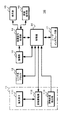
図1は、撮像装置の構成を例示している。撮像装置10は、偏光回転部11、レンズ系ブロック12、撮像部13、画像信号処理部14、表示部15、画像保存部16、ユーザインタフェース部17、制御部20を有している。
1. Configuration of imaging apparatus Operation of imaging apparatus 2-1. Imaging operation emphasizing dynamic range and resolution 2-2. 2. Imaging operation example 3. Other configuration of imaging device Application example <1. Configuration of Imaging Device>
FIG. 1 illustrates the configuration of the imaging apparatus. The
偏光回転部11は、撮像部13の入射面側に設けられて偏光回転部11に入射される被写体光から特定の偏波のみを通して撮像部13に入射させる。また、偏光回転部11は、透過光の偏波面(以下「入射光の偏光方向」という)を回転自在とする。偏光回転部11は、例えば偏光素子111と回転駆動部112を用いて構成されている。偏光素子111は、直線偏光を生成する偏光素子、例えばワイヤーグリッド等を用いて構成された偏光フィルタ等の直線偏光素子である。回転駆動部112は、制御部20からの指示に基づき偏光素子111を駆動して、偏光素子111の偏光方向を、撮像部13に入射される入射光の光軸方向を回転軸として回転させる。回転位置検出部113は、偏光素子111の回転位置を検出して、検出した回転位置を示す回転位置情報を生成して制御部20へ出力する。なお、偏光素子111は、回転駆動部112によって回転される構成に限らず手動で回転できる構成とされていてもよい。
The
レンズ系ブロック12は、フォーカスレンズやズームレンズ、絞り機構等を有している。また、レンズ系ブロック12には、制御部20からの指示に基づきレンズや絞り機構を駆動する駆動部を有している。レンズ系ブロック12は、制御部20からの指示に基づきフォーカスレンズやズームレンズの位置を制御して、被写体光学像を撮像部13の露光面に結像させる。レンズ系ブロック12は、制御部20からの指示に基づき絞りの開度を制御して被写体光の光量を調整する。なお、フォーカスレンズやズームレンズおよび絞りの位置は、ユーザ操作に応じて機械的に移動可能とされていてもよい。
The
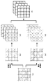
撮像部13は、CMOS(Complementary Metal Oxide Semiconductor)イメージセンサまたはCCD(Charge Coupled Device)イメージセンサ等を用いて構成されている。また、イメージセンサの入射面には所定偏光方向の画素が画面上で均等となるように所定間隔で配置する偏光フィルタが設けられている。図2は撮像部の構成を例示している。撮像部13は、イメージセンサ131の入射面に、水平方向および垂直方向に対して1画素おきに所定偏光方向の画素を配置する偏光フィルタ132を設けた場合を例示している。撮像部13は、生成した偏光画素と非偏光画素の画像信号を画像信号処理部14へ出力する。なお、所定偏光方向(例えば偏光方向が「0°」)の画素を偏光画素CP、非偏光である画素を非偏光画素CNとする。
The
画像信号処理部14は、撮像部13から出力された画像信号に対して、ノイズ除去処理、ゲイン調整処理、欠陥画素補正処理、デモザイク処理、色調整処理、解像度変換処理などの各種の画像処理を行う。また、画像信号処理部14は、撮像部13に入射される入射光の偏光方向の回転位置に応じたダイナミックレンジの撮像画の画像信号を生成を、例えば非偏光画素と偏光画素の感度差が閾値よりも大きい場合に行う。画像信号処理部14は、感度差が閾値よりも大きい場合、撮像部13の偏光画素の感度に応じて偏光画素に対する利得調整を行い、利得調整後の画像信号を用いて画像合成を行う。画像信号処理部14は、処理後の画像信号を表示部15と画像保存部16に出力する。また、画像信号処理部14は、撮像部13から出力された画像信号に基づき、非偏光画素群の信号強度分布や偏光画素群の信号強度分布の解析結果を示す情報、例えば色成分毎の信号強度分布や輝度の信号強度分布を示すヒストグラムを画像解析情報として生成して表示部15へ出力してもよい。なお、画像信号処理部14は、制御部20からの制御のもと、撮像装置10の設定操作や設定状態の確認等を行うためのメニュー表示や撮像時における設定状態等に関する情報表示を行う表示信号を画像信号に重畳して表示部15等に出力する。また、画像信号処理部14は、感度検出部の動作を行う場合、撮像部13から供給された画像信号に基づき、撮像部13における偏光画素の感度と非偏光画素の感度や偏光画素と非偏光画素との感度差,感度比を算出する。撮像部13における偏光画素および非偏光画素の感度とは、偏光回転部11を介して被写体光を撮像部に入射したときの偏光画素および非偏光画素の感度であり、偏光画素の感度は、偏光回転部11の偏光方向と偏光画素の偏光方向の関係に応じて変化する。画像信号処理部14は、例えば偏光回転部11を介して画素飽和を生じない明るさの被写体を撮像したときの偏光画素と非偏光画素の信号強度から感度および感度差,感度比を算出する。
The image
表示部15は、液晶ディスプレイや、有機EL(EL:Electro luminescence)ディスプレイなどにより構成される。表示部15は、その画面上に撮像画や各種情報を表示させる。例えば、表示部15は、画像信号処理部14から出力された画像データに基づき、画面上にスルー画を表示する。また、表示部15は、画像保存部16に記録された画像が画像信号処理部14で再生されたとき再生画像を画面上に表示する。さらに、表示部15は、メニュー表示や情報表示を行う。
The
画像保存部16は、画像信号処理部14から出力された画像データや、その画像データに関連するメタデータ(例えば、その画像データが取得された日時等)を記憶する。画像保存部16は、例えば、半導体メモリ、光ディスク、HD(hard Disc)などにより構成される。画像保存部16は、撮像装置10の内部に固定して設けられてもよく、撮像装置10に対して着脱可能に設けられてもよい。
The
ユーザインタフェース部17はシャッターボタンや操作スイッチ、タッチパネル等で構成されている。ユーザインタフェース部17は、シャッターボタン、偏光フィルタ回転操作ボタン、種々の操作スイッチ、タッチパネル等に対するユーザ操作に応じた操作信号を生成して制御部20へ出力する。
The
制御部20は、CPU(Central Processing Unit)やROM(Read Only Memory),RAM(Random Access Memory)等を有している。ROM(Read Only Memory)は、CPU(Central Processing Unit)により実行される各種プログラムを記憶する。RAM(Random Access Memory)は、各種パラメータ等の情報を記憶する。CPUは、ROMに記憶されている各種プログラムを実行して、ユーザインタフェース部17からの操作信号に基づき、ユーザ操作に応じた動作モードで撮像動作が撮像装置10で行われるように各部を制御する。
The
制御部20は、感度検出部としての動作を行う場合、偏光素子回転部11からの回転位置情報に基づき、偏光素子回転部11の偏光素子111と撮像部13の偏光フィルタ132で偏光方向の違い(偏光方向相違角)を算出する。また、偏光方向の違いに対応する非偏光画素の感度を予め算出しておくことで、回転位置情報に基づき偏光画素の感度や感度差,感度比を算出できる。制御部20は、算出した偏光方向相違角または画像信号処理部14で算出された偏光画素と非偏光画素の感度差に基づき、ダイナミックレンジ重視撮像モードとするか、解像度重視撮像モードとするか判別する。制御部20は、偏光方向相違角または感度差が閾値を超える場合、ダイナミックレンジ重視モードと判定する。ダイナミックレンジ重視モードと判定した場合、制御部20は画像信号処理部14において、偏光画素について感度に応じて利得調整と、利得調整後の画素信号と非偏光画素の画素信号を用いた画像合成を行い、広ダイナミックレンジの撮像画の画像信号を生成させる。また、制御部20は、偏光方向相違角または感度差が閾値以下である場合、解像度重視モードと判別して、画像信号処理部14で非偏光画素の感度に応じた利得調整や画像合成を行うことなく解像度の低下のない撮像画の画像信号を生成させる。なお、閾値は、例えば撮像画において偏光画素と非偏光画素との感度差による影響を許容できる最大値とする。
When the
<2.撮像装置の動作>
次に撮像装置の動作について説明する。図3は撮像装置の動作を示すフローチャートである。ステップST1で制御部は撮像設定処理を行う。図4は撮像設定処理を示すフローチャートである。
<2. Operation of Imaging Device>
Next, the operation of the imaging apparatus will be described. FIG. 3 is a flowchart showing the operation of the imaging apparatus. In step ST1, the control unit performs an imaging setting process. FIG. 4 is a flowchart showing the imaging setting process.
ステップST11で制御部は偏光素子状態情報を取得する。制御部20は、偏光回転部11の回転位置検出部113から偏光素子111の回転位置を示す回転位置情報、または画像信号処理部14から偏光画素と非偏光画素の感度差を取得してステップST12に進む。
In step ST11, the control unit acquires polarization element state information. The
ステップST12で制御部は感度差が閾値を超えているか判別する。制御部20は、回転位置情報を取得した場合、撮像部13における偏光フィルタ132の偏光方向に対する偏光回転部11における偏光素子111の偏光方向の違いを示す偏光方向相違角を算出する。また、制御部20は、偏光方向相違角に基づき偏光画素と非偏光画素の感度差を算出する。制御部20は回転位置情報に基づき算出した感度差または画像信号処理部14から取得した感度差が閾値を超える場合はステップST13に進み、閾値以下である場合はステップST14に進む。
In step ST12, the control unit determines whether the sensitivity difference exceeds a threshold value. When the rotation position information is acquired, the
ステップST13で制御部はダイナミックレンジ重視撮像モード設定処理を行う。制御部20は、被写体の輝度に応じて撮像部13の露光時間等の設定を行う。また、制御部20は、偏光画素と非偏光画素の感度に基づく利得制御と、利得調整後の画像信号を用いた画像合成を行い、広ダイナックレンジ画像を生成するように画像信号処理部14の動作を設定する。なお、制御部20は、画像信号処理部14でノイズ除去処理や欠陥画素補正処理、デモザイク処理、色調整処理、解像度変換処理などの各種の画像処理も合わせて行うようにして図3のステップST2に進む。
In step ST13, the control unit performs dynamic range-oriented imaging mode setting processing. The
ステップST14で制御部は解像度重視撮像モード設定処理を行う。制御部20は、被写体の輝度に応じて露光時間等の設定を行う。なお、制御部20は、画像信号処理部14でノイズ除去処理や欠陥画素補正処理、デモザイク処理、色調整処理、解像度変換処理などの各種の画像処理も合わせて行うようにして図3のステップST2に進む。
In step ST14, the control unit performs resolution-oriented imaging mode setting processing. The
ステップST2で制御部はスルー画表示処理を行う。制御部20はステップST1の撮像設定に基づき撮像部13を制御して画像信号を生成させて表示部15でスルー画の表示を行いステップST3に進む。
In step ST2, the control unit performs a through image display process. The
ステップST3で制御部は撮像終了であるか判別する。制御部20は、撮像装置の動作モードが被写体を撮像して記録画を保存する動作モードから他の動作モードに切り替えられていない場合、および撮像装置の動作を終了する終了操作が行われていない場合は撮像終了でないと判別してステップST1に戻る。また、制御部20は、他の動作モードへの切替操作や終了操作が行われた場合動作を終了する。
In step ST <b> 3, the control unit determines whether imaging has been completed. When the operation mode of the imaging device has not been switched from the operation mode in which the imaging device captures an image of the subject and saves the recorded image to another operation mode, and the termination operation for ending the operation of the imaging device has not been performed. In this case, it is determined that the imaging is not finished, and the process returns to step ST1. Moreover, the
制御部は、図3に示すステップST1からステップST3までの処理中にシャッター操作が行われた場合、図5に示す割り込み処理を行う。ステップST21で制御部は記録画生成処理を行う。制御部20は、撮像モードがダイナミックレンジ重視撮像モードである場合、ダイナミックレンジ重視撮像モード設定処理の撮像設定で撮像部13と画像信号処理部14を動作させて広ダイナミックレンジ画像の画像信号を生成する。また、制御部20は、撮像モードが解像度重視撮像モードである場合、解像度重視撮像モード設定処理の撮像設定で撮像部13を駆動して偏光撮像画の画像信号を生成する。制御部20は、ダイナミックレンジの広いまたは解像度の低下がない撮像画の画像信号を生成してステップST22に進む。なお、ダイナミックレンジ重視撮像モードと解像度重視撮像モードの撮像動作については後述する。
When the shutter operation is performed during the process from step ST1 to step ST3 shown in FIG. 3, the control unit performs the interrupt process shown in FIG. In step ST21, the control unit performs a recording image generation process. When the imaging mode is the dynamic range emphasizing imaging mode, the
ステップST22で制御部は画像保存処理を行う。制御部20はステップST21で生成した画像信号を画像信号処理部14へ出力して種々の処理を行い、処理後の画像信号を画像保存部16に記憶させて割り込み処理を終了する。
In step ST22, the control unit performs image storage processing. The
<2−1.ダイナミックレンジ重視と解像度重視の撮像動作>
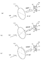
次に撮像装置におけるダイナミックレンジ重視の撮像動作について説明する。図6は、入射光と偏光素子を透過した直線偏光および撮像部の関係を示している。偏光素子111に入射光LAが入射されると、偏光素子111は直線偏光LBを透過して撮像部13に入射する。また、撮像部13に入射される入射光の光軸方向を回転軸として偏光素子111を回転すると、直線偏光LBの偏光方向が変化する。例えば図6の(a)に示すように偏光素子111の回転角θが「θ=0°」である場合、直線偏光LBと撮像部13における偏光画素CPと偏光方向が等しくなる。また、図6の(b)に示すように偏光素子111の回転角θが「θ=45°」である場合、直線偏光LBと撮像部13における偏光画素CPで偏光方向の角度差を生じる。また、図6の(c)に示すように偏光素子111の回転角θが「θ=90°」である場合、直線偏光LBと撮像部13における偏光画素CPの偏光方向は直交する方向となる。
<2-1. Imaging operation with emphasis on dynamic range and resolution>
Next, an imaging operation with an emphasis on dynamic range in the imaging apparatus will be described. FIG. 6 shows the relationship between the incident light, the linearly polarized light transmitted through the polarizing element, and the imaging unit. When the incident light LA is incident on the
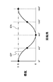
図7は、偏光素子の回転角と撮像部における偏光画素の感度の関係を例示している。偏光素子111は、図6に示すように、撮像部13に入射される入射光の光軸方向を回転軸として回転可能に構成されている。ここで、偏光素子111を回転して偏光方向を変化させた場合、撮像部13における偏光画素CPの感度は、撮像素子の回転角に応じて変化する。
FIG. 7 illustrates the relationship between the rotation angle of the polarizing element and the sensitivity of the polarizing pixel in the imaging unit. As shown in FIG. 6, the
例えば、偏光方向が「0°」とされている偏光画素CPの感度は、偏光素子111の回転角θが「θ=0°」である場合に最大(例えば0.5)となる。その後、偏光画素CPの感度は、偏光素子111の偏光方向の回転と共に減少して偏光素子111の回転角θが「θ=90°」である場合に最小(例えば0)となる。さらに、偏光素子111の偏光方向が回転させると、回転と共に感度が増加して、偏光素子111の回転角θが「θ=180°」である場合に最大(例えば0.5)となる。
For example, the sensitivity of the polarization pixel CP whose polarization direction is “0 °” is maximized (for example, 0.5) when the rotation angle θ of the
制御部20は、非偏光画素CNと偏光画素CPの感度比に基づき、偏光画素CPの利得を設定して画像信号処理部14へ出力する。例えば、非偏光画素CNが感度「0.5」、偏光画素CPが感度「SE」である場合、感度比「0.5/SE」を偏光画素CPの利得GAnpとして設定して、画像信号処理部14へ出力する。なお、感度や感度比の算出は上述のように画像信号処理部14で行ってもよい。
The
画像信号処理部14は、設定された利得を用いて利得調整を行い、利得調整後に画像合成を行う。図8は、利得調整と画像合成を説明するための図である。図8の(a)は入射光に対する偏光画素の信号強度を例示している。例えば非偏光画素CNでは入射光が輝度LR1となる場合に信号強度IMsatで飽和する。また、偏光画素CPでは入射光が輝度LR1よりも高い輝度LR2となる場合に信号強度IMsatで飽和する。画像信号処理部14は非偏光画素CNで飽和を生じる場合、図8の(b)に示すように、感度に応じた利得GAnpで偏光画素CPの画素信号を増幅して画像合成を行い、入射光が輝度LR1より高くなっても飽和を生じていない広ダイナミックレンジの画像信号を生成できる。なお、入射光が輝度LR1以上となったか否かの判別は、撮像部13からの画像信号の信号レベルに基づき判別できる。
The image
また、画像信号処理部14は、画像合成において、非偏光画素CNに基づく画像から偏光画素CPの利得調整後の画像への切替が目立たないように合成比を入射光(撮像部13からの画像信号の信号レベル)に応じて設定してもよい。図9は、入射光と合成比の関係を例示している。画像信号処理部14は、非偏光画素CNが飽和を生じる輝度LR1となる前に合成比の調整を行い、飽和を生じる輝度LR1であるときは、非偏光画素CNに基づく画像から偏光画素CPの利得調整後の画像への切替が完了するように合成比を設定する。
Further, the image
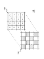
図10は撮像部の具体例を示している。撮像部13は、2×2画素を色単位として色配列をベイヤー配列としたモザイクカラーフィルタと、水平方向および垂直方向に対してそれぞれ1画素置きに偏光画素が設けられる偏光フィルタ132を撮像部の入射面側に設けた構成とされている。
FIG. 10 shows a specific example of the imaging unit. The
図11は画像信号処理部の動作例を示している。画像信号処理部14は、図11の(a)に示す撮像部から図11の(b)に示す非偏光画素群と図11の(c)に示す偏光画素群に分割する。画像信号処理部14は非偏光画素群の画素信号を用いて画素補間およびデモザイク処理を行い、図11の(d)に示すように色成分毎の撮像画(以下「非偏光画素群画像」という)の画像信号を生成する。また、画像信号処理部14は偏光画素の画素信号を用いて画素補間およびデモザイク処理を行い、図11の(e)に示すように色成分毎の撮像画(以下「偏光画素群画像」という)の画像信号を生成する。なお、偏光画素群画像は非偏光画素群画像以下の感度である。画像信号処理部14は、非偏光画素群画像の画素毎に画像信号が飽和を生じるか判別する。画像信号処理部14は、非偏光画素群画像の画像信号が飽和する場合、感度比に応じた利得で増幅した偏光画素群画像における対応画素位置の画像信号を用いて入射光(非偏光画素の画像信号)に応じた合成比で画像合成を行い、図11の(f)に示す広ダイナミックレンジである色成分毎の画像信号を生成する。
FIG. 11 shows an operation example of the image signal processing unit. The image
解像度重視の撮像動作では、偏光画素と非偏光画素の感度差が許容範囲であることから、画像信号処理部14は非偏光画素群と偏光画素群に分割することなく、各画素の画素信号を用いて画素補間およびデモザイク処理を行い、色成分毎の画像信号を、解像度の劣化を生じることなく生成する。
In the resolution-oriented imaging operation, the sensitivity difference between the polarized pixel and the non-polarized pixel is within an allowable range. Therefore, the image
撮像装置10では、このような処理を行うことで、偏光素子111を回転させるだけで、ダイナミックレンジ重視の撮像画または解像度重視の撮像画を生成できる。また、ダイナミックレンジ重視の撮像画を生成する場合、等しい露光時間で同時に感度の異なる撮像画を生成できることから、動きを生じた暗い被写体を撮像する場合でも動きによるぼけのない広ダイナミックレンジ画像を生成できる。さらに、偏光素子111を回転させることで、偏光画素の感度を調整できるので、ダイナミックレンジ重視の撮像モードにおいて、偏光素子111の回転量を調整するだけで、所望のダイナミックレンジの画像を生成できる。また、解像度の低下を生じていない撮像画の生成を行うこともできる。
By performing such processing, the
<2−2.撮像動作例>
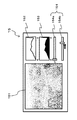
次に、撮像動作例について説明する。図12〜図17は表示部の表示画面を例示している。表示画面では、画像表示領域151と非偏光画素群ヒストグラム表示領域152、偏光画素群ヒストグラム表示領域153、ユーザインタフェース表示領域154が設けられている。
<2-2. Imaging operation example>
Next, an example of an imaging operation will be described. 12 to 17 exemplify display screens of the display unit. On the display screen, an
画像表示領域151では画像信号処理部14から出力された画像信号に基づき例えばスルー画や記録画像が表示される。非偏光画素群ヒストグラム表示領域152では、画像信号処理部14で生成された画像解析情報に基づき非偏光画素の信号強度ヒストグラムが表示される。偏光画素群ヒストグラム表示領域153では、画像信号処理部14で生成された画像解析情報に基づき偏光画素の信号強度のヒストグラムが表示される。なお、ヒストグラムでは、色成分毎のヒストグラムを表示してもよく輝度のヒストグラムを生成してもよい。ユーザインタフェース表示領域154では、偏光素子111の回転位置を設定するスライダー154aとISO感度を設定するスライダー154bが設けられている。なお、偏光素子111の回転位置の設定やISO感度の設定は、スライダーを用いる場合に限らずダイヤル等を用いるようにしてもよい。
In the
図12は、回転角が「0°」とされており解像度重視撮影モードで撮像が行われている場合を例示している。画像表示領域151に表示されている撮像画は、ヒストグラムの表示からも明らかなように、飽和を生じていない適正な露出の画像となっている。
FIG. 12 illustrates a case where the rotation angle is “0 °” and the imaging is performed in the resolution-oriented imaging mode. The captured image displayed in the
図13は、回転角が「0°」とされており、すべての画素の感度が同一になっている状態で、被写体画像の飽和が生じた場合を例示している。例えば空が非常に明るい場合、空の領域の偏光画素と非偏光画素では飽和を生じて、ヒストグラムでは信号強度の高い階級で度数が高くなっている。このような場合、偏光素子111を回転させてダイナックレンジを広くする。図14は、偏光素子111を回転させてダイナックレンジを広くした場合を示している。偏光素子111を回転させると偏光画素の感度が低くなる。なお、偏光画素の感度が低くなったことで、偏光画素群のヒストグラムでは信号強度の高い階級の度数が低下している。このように、偏光素子111を回転させて撮像偏光画素の感度が低くなると、撮像モードがダイナミックレンジ重視撮影モードに切り替わる。この場合、画像信号処理部14では、非偏光画素に基づく画像と偏光画素に基づく偏光画素の感度に応じて利得調整が行われた画像が合成されて、画像表示領域151に表示される画像は、飽和を生じていない広ダイナミックレンジの撮像画となる。
FIG. 13 illustrates a case where the subject image is saturated in a state where the rotation angle is “0 °” and the sensitivity of all the pixels is the same. For example, when the sky is very bright, saturation occurs in polarized pixels and non-polarized pixels in the sky region, and in the histogram, the frequency is high in a class with high signal intensity. In such a case, the
図15は、回転角が「0°」とされており、すべての画素の感度が同一になっている状態で、被写体が暗く黒潰れが生じた場合を例示している。例えば日陰が暗く、日陰の領域の偏光画素と非偏光画素では信号強度が最低となり、ヒストグラムでは信号強度の低い階級で度数が高くなっている。このような場合、図16に示すように、ISO感度を高くすることで撮像画を明るくできる。しかし、ISO感度を高くすることで例えば空の領域の偏光画素と非偏光画素で飽和を生じてしまう場合がある。なお、ISO感度を高くすることで、ヒストグラムでは信号強度の高い階級で度数が高くなっている。 FIG. 15 exemplifies a case where the subject is dark and blacked out in a state where the rotation angle is “0 °” and the sensitivity of all the pixels is the same. For example, the shade is dark and the signal intensity is the lowest in the polarized pixels and the non-polarized pixels in the shaded area, and in the histogram, the frequency is high in the class with the low signal intensity. In such a case, as shown in FIG. 16, the captured image can be brightened by increasing the ISO sensitivity. However, when the ISO sensitivity is increased, saturation may occur in, for example, a polarized pixel and a non-polarized pixel in the sky region. Note that by increasing the ISO sensitivity, in the histogram, the frequency is high in a class with high signal intensity.
ここで、偏光素子111を回転させると偏光画素の感度が低くなる。図17は、図16の状態から偏光素子111を回転させてダイナックレンジを広くした場合を示している。なお、偏光画素の感度が低くなったことで、偏光画素群のヒストグラムでは信号強度の高い階級の度数が低下している。このように、偏光素子111を回転させて偏光画素の感度が低くなると、撮像モードがダイナミックレンジ重視撮影モードに切り替わる。この場合、画像信号処理部14は、非偏光画素に基づく画像と偏光画素に基づく偏光画素の感度に応じて利得調整が行われた画像を合成して、画像表示領域151に表示される画像は、飽和を生じていない広ダイナミックレンジの撮像画となる。
Here, when the
このように、ユーザは、偏光素子111を回転させるだけで、ダイナミックレンジ重視の撮像画または解像度重視の撮像画を生成できる。また、偏光素子111を回転させることで、偏光画素の感度を調整できるので、ダイナミックレンジ重視の撮像モードにおいて、偏光素子111の回転量を調整するだけで、所望のダイナミックレンジの画像を生成できる。また、表示部15にはユーザインタフェース画像が表示されていることから、画面上で、撮像部13に入射される入射光の偏光方向を変化させることができる。また、非偏光画素群ヒストグラムを表示することで、画素が飽和してダイナミックレンジを広げる必要があるかを画面上で確認できる。さらに、偏光画素群ヒストグラムを表示することで、ダイナミックレンジの拡大が最適に行われているかを画面上で確認できる。例えば偏光画素群ヒストグラムで信号強度の最も高い階級の度数が高い場合は、ダイナミックレンジの拡大が不足しており、信号強度の最も低い階級の度数が高い場合、または、高い階級の度数が揃って0になっている場合は、ダイナミックレンジの拡大が過大であることを判別できる。
In this way, the user can generate a captured image with an emphasis on dynamic range or an image with an emphasis on resolution simply by rotating the
なお、図12〜図17の表示画面は一例であって、例えば入射光の偏光方向や拡大されたダイナミックレンジを数値や図で表示してもよい。また、偏光素子111を回転させることで偏光画素群のヒストグラムが変化することから、表示するヒストグラムは偏光画素群のみであってもよい。
Note that the display screens of FIGS. 12 to 17 are examples, and for example, the polarization direction of the incident light and the expanded dynamic range may be displayed as numerical values or diagrams. Further, since the histogram of the polarization pixel group changes by rotating the
<3.撮像装置の他の構成>
上述の実施の形態では、偏光回転部11をレンズ系ブロック12の入射光面側に設けた構成を例示したが、偏光回転部11は撮像部13の入射光面側の位置であればよい。図18は撮像装置の他の構成を例示しており、撮像装置10aでは、レンズ系ブロック12と撮像部13との間に偏光回転部11を設けている。
<3. Other Configuration of Imaging Device>
In the above-described embodiment, the configuration in which the
また、撮像部の構成は、図10に示すように、2×2画素を色単位内で斜め方向に偏光画を設ける場合に限られない。図19は、撮像部の他の構成を例示している。図19の(a)は、2×2画素を色単位内で水平方向に偏光画を設けた場合を示している。また、図19の(b)は、撮像部13の色単位を1画素として、垂直方向の2画素を偏光画素として、この2画素の偏光画素ブロックを水平方向に1画素置きで垂直方向に2画素置きに配置した場合を例示している。このように、色成分単位を1画素単位とすれば、2×2画素の色成分単位に比べて色成分画素の配置の偏りが小さく画質を良くすることが可能となる。
Further, the configuration of the imaging unit is not limited to the case where the polarization image is provided in the diagonal direction within the color unit of 2 × 2 pixels as shown in FIG. FIG. 19 illustrates another configuration of the imaging unit. FIG. 19A shows a case in which a 2 × 2 pixel is provided with a polarization image in the horizontal direction within a color unit. FIG. 19B shows that the color unit of the
また、偏光回転部11における偏光素子111の回転は、ユーザ操作に限らず撮像部13で生成される画素信号に応じて自動的に行うようにしてもよい。例えば画像信号処理部14で生成された画像解析情報を制御部20へ出力して、制御部20は偏光画素群ヒストグラムに基づき偏光画素で飽和を生じないように偏光素子111を回転してもよい。この場合、撮像範囲の被写体に応じて飽和を生じないようにダイナミックレンジを自動的に調整することが可能となる。
Further, the rotation of the
また、偏光回転部11は、偏光素子111と回転駆動部112を用いた構成に限らず、特開平10−268249号公報で開示されている液晶素子を用いた偏光回転素子等の技術を用いた構成としてもよい。例えば、撮像部の入射面側に入射光のうち特定の偏波のみを通す偏光素子を設けて、この偏光素子を透過した偏波光を、液晶素子を用いた偏光回転部で回転させる。このような構成とすれば、偏光素子111を回転させる機構を設けることなく、偏光方向の回転を容易に行うことができる。
Further, the
<4.応用例>
本開示に係る技術は、様々な製品へ応用することができる。例えば、本開示に係る技術は、情報処理端末に限らず、自動車、電気自動車、ハイブリッド電気自動車、自動二輪車、自転車、パーソナルモビリティ、飛行機、ドローン、船舶、ロボット、建設機械、農業機械(トラクター)などのいずれかの種類の移動体に搭載される装置として実現されてもよい。
<4. Application example>
The technology according to the present disclosure can be applied to various products. For example, the technology according to the present disclosure is not limited to an information processing terminal, but is an automobile, an electric car, a hybrid electric car, a motorcycle, a bicycle, a personal mobility, an airplane, a drone, a ship, a robot, a construction machine, an agricultural machine (tractor), etc. It may be realized as an apparatus mounted on any kind of moving body.
図20は、本開示に係る技術が適用され得る移動体制御システムの一例である車両制御システム7000の概略的な構成例を示すブロック図である。車両制御システム7000は、通信ネットワーク7010を介して接続された複数の電子制御ユニットを備える。図20に示した例では、車両制御システム7000は、駆動系制御ユニット7100、ボディ系制御ユニット7200、バッテリ制御ユニット7300、車外情報検出ユニット7400、車内情報検出ユニット7500、及び統合制御ユニット7600を備える。これらの複数の制御ユニットを接続する通信ネットワーク7010は、例えば、CAN(Controller Area Network)、LIN(Local Interconnect Network)、LAN(Local Area Network)又はFlexRay(登録商標)等の任意の規格に準拠した車載通信ネットワークであってよい。
FIG. 20 is a block diagram illustrating a schematic configuration example of a
各制御ユニットは、各種プログラムにしたがって演算処理を行うマイクロコンピュータと、マイクロコンピュータにより実行されるプログラム又は各種演算に用いられるパラメータ等を記憶する記憶部と、各種制御対象の装置を駆動する駆動回路とを備える。各制御ユニットは、通信ネットワーク7010を介して他の制御ユニットとの間で通信を行うためのネットワークI/Fを備えるとともに、車内外の装置又はセンサ等との間で、有線通信又は無線通信により通信を行うための通信I/Fを備える。図20では、統合制御ユニット7600の機能構成として、マイクロコンピュータ7610、汎用通信I/F7620、専用通信I/F7630、測位部7640、ビーコン受信部7650、車内機器I/F7660、音声画像出力部7670、車載ネットワークI/F7680及び記憶部7690が図示されている。他の制御ユニットも同様に、マイクロコンピュータ、通信I/F及び記憶部等を備える。
Each control unit includes a microcomputer that performs arithmetic processing according to various programs, a storage unit that stores programs executed by the microcomputer or parameters used for various calculations, and a drive circuit that drives various devices to be controlled. Is provided. Each control unit includes a network I / F for communicating with other control units via a
駆動系制御ユニット7100は、各種プログラムにしたがって車両の駆動系に関連する装置の動作を制御する。例えば、駆動系制御ユニット7100は、内燃機関又は駆動用モータ等の車両の駆動力を発生させるための駆動力発生装置、駆動力を車輪に伝達するための駆動力伝達機構、車両の舵角を調節するステアリング機構、及び、車両の制動力を発生させる制動装置等の制御装置として機能する。駆動系制御ユニット7100は、ABS(Antilock Brake System)又はESC(Electronic Stability Control)等の制御装置としての機能を有してもよい。
The drive
駆動系制御ユニット7100には、車両状態検出部7110が接続される。車両状態検出部7110には、例えば、車体の軸回転運動の角速度を検出するジャイロセンサ、車両の加速度を検出する加速度センサ、あるいは、アクセルペダルの操作量、ブレーキペダルの操作量、ステアリングホイールの操舵角、エンジン回転数又は車輪の回転速度等を検出するためのセンサのうちの少なくとも一つが含まれる。駆動系制御ユニット7100は、車両状態検出部7110から入力される信号を用いて演算処理を行い、内燃機関、駆動用モータ、電動パワーステアリング装置又はブレーキ装置等を制御する。
A vehicle
ボディ系制御ユニット7200は、各種プログラムにしたがって車体に装備された各種装置の動作を制御する。例えば、ボディ系制御ユニット7200は、キーレスエントリシステム、スマートキーシステム、パワーウィンドウ装置、あるいは、ヘッドランプ、バックランプ、ブレーキランプ、ウィンカー又はフォグランプ等の各種ランプの制御装置として機能する。この場合、ボディ系制御ユニット7200には、鍵を代替する携帯機から発信される電波又は各種スイッチの信号が入力され得る。ボディ系制御ユニット7200は、これらの電波又は信号の入力を受け付け、車両のドアロック装置、パワーウィンドウ装置、ランプ等を制御する。
The body
バッテリ制御ユニット7300は、各種プログラムにしたがって駆動用モータの電力供給源である二次電池7310を制御する。例えば、バッテリ制御ユニット7300には、二次電池7310を備えたバッテリ装置から、バッテリ温度、バッテリ出力電圧又はバッテリの残存容量等の情報が入力される。バッテリ制御ユニット7300は、これらの信号を用いて演算処理を行い、二次電池7310の温度調節制御又はバッテリ装置に備えられた冷却装置等の制御を行う。
The
車外情報検出ユニット7400は、車両制御システム7000を搭載した車両の外部の情報を検出する。例えば、車外情報検出ユニット7400には、撮像部7410及び車外情報検出部7420のうちの少なくとも一方が接続される。撮像部7410には、ToF(Time Of Flight)カメラ、ステレオカメラ、単眼カメラ、赤外線カメラ及びその他のカメラのうちの少なくとも一つが含まれる。車外情報検出部7420には、例えば、現在の天候又は気象を検出するための環境センサ、あるいは、車両制御システム7000を搭載した車両の周囲の他の車両、障害物又は歩行者等を検出するための周囲情報検出センサのうちの少なくとも一つが含まれる。
The outside
環境センサは、例えば、雨天を検出する雨滴センサ、霧を検出する霧センサ、日照度合いを検出する日照センサ、及び降雪を検出する雪センサのうちの少なくとも一つであってよい。周囲情報検出センサは、超音波センサ、レーダ装置及びLIDAR(Light Detection and Ranging、Laser Imaging Detection and Ranging)装置のうちの少なくとも一つであってよい。これらの撮像部7410及び車外情報検出部7420は、それぞれ独立したセンサないし装置として備えられてもよいし、複数のセンサないし装置が統合された装置として備えられてもよい。
The environmental sensor may be, for example, at least one of a raindrop sensor that detects rainy weather, a fog sensor that detects fog, a sunshine sensor that detects sunlight intensity, and a snow sensor that detects snowfall. The ambient information detection sensor may be at least one of an ultrasonic sensor, a radar device, and a LIDAR (Light Detection and Ranging, Laser Imaging Detection and Ranging) device. The
ここで、図21は、撮像部7410及び車外情報検出部7420の設置位置の例を示す。撮像部7910,7912,7914,7916,7918は、例えば、車両7900のフロントノーズ、サイドミラー、リアバンパ、バックドア及び車室内のフロントガラスの上部のうちの少なくとも一つの位置に設けられる。フロントノーズに備えられる撮像部7910及び車室内のフロントガラスの上部に備えられる撮像部7918は、主として車両7900の前方の画像を取得する。サイドミラーに備えられる撮像部7912,7914は、主として車両7900の側方の画像を取得する。リアバンパ又はバックドアに備えられる撮像部7916は、主として車両7900の後方の画像を取得する。車室内のフロントガラスの上部に備えられる撮像部7918は、主として先行車両又は、歩行者、障害物、信号機、交通標識又は車線等の検出に用いられる。
Here, FIG. 21 shows an example of installation positions of the
なお、図21には、それぞれの撮像部7910,7912,7914,7916の撮影範囲の一例が示されている。撮像範囲aは、フロントノーズに設けられた撮像部7910の撮像範囲を示し、撮像範囲b,cは、それぞれサイドミラーに設けられた撮像部7912,7914の撮像範囲を示し、撮像範囲dは、リアバンパ又はバックドアに設けられた撮像部7916の撮像範囲を示す。例えば、撮像部7910,7912,7914,7916で撮像された画像データが重ね合わせられることにより、車両7900を上方から見た俯瞰画像が得られる。
FIG. 21 shows an example of the shooting range of each of the
車両7900のフロント、リア、サイド、コーナ及び車室内のフロントガラスの上部に設けられる車外情報検出部7920,7922,7924,7926,7928,7930は、例えば超音波センサ又はレーダ装置であってよい。車両7900のフロントノーズ、リアバンパ、バックドア及び車室内のフロントガラスの上部に設けられる車外情報検出部7920,7926,7930は、例えばLIDAR装置であってよい。これらの車外情報検出部7920〜7930は、主として先行車両、歩行者又は障害物等の検出に用いられる。
The vehicle outside
図20に戻って説明を続ける。車外情報検出ユニット7400は、撮像部7410に車外の画像を撮像させるとともに、撮像された画像データを受信する。また、車外情報検出ユニット7400は、接続されている車外情報検出部7420から検出情報を受信する。車外情報検出部7420が超音波センサ、レーダ装置又はLIDAR装置である場合には、車外情報検出ユニット7400は、超音波又は電磁波等を発信させるとともに、受信された反射波の情報を受信する。車外情報検出ユニット7400は、受信した情報に基づいて、人、車、障害物、標識又は路面上の文字等の物体検出処理又は距離検出処理を行ってもよい。車外情報検出ユニット7400は、受信した情報に基づいて、降雨、霧又は路面状況等を認識する環境認識処理を行ってもよい。車外情報検出ユニット7400は、受信した情報に基づいて、車外の物体までの距離を算出してもよい。
Returning to FIG. 20, the description will be continued. The vehicle exterior
また、車外情報検出ユニット7400は、受信した画像データに基づいて、人、車、障害物、標識又は路面上の文字等を認識する画像認識処理又は距離検出処理を行ってもよい。車外情報検出ユニット7400は、受信した画像データに対して歪補正又は位置合わせ等の処理を行うとともに、異なる撮像部7410により撮像された画像データを合成して、俯瞰画像又はパノラマ画像を生成してもよい。車外情報検出ユニット7400は、異なる撮像部7410により撮像された画像データを用いて、視点変換処理を行ってもよい。
Further, the outside
車内情報検出ユニット7500は、車内の情報を検出する。車内情報検出ユニット7500には、例えば、運転者の状態を検出する運転者状態検出部7510が接続される。運転者状態検出部7510は、運転者を撮像するカメラ、運転者の生体情報を検出する生体センサ又は車室内の音声を集音するマイク等を含んでもよい。生体センサは、例えば、座面又はステアリングホイール等に設けられ、座席に座った搭乗者又はステアリングホイールを握る運転者の生体情報を検出する。車内情報検出ユニット7500は、運転者状態検出部7510から入力される検出情報に基づいて、運転者の疲労度合い又は集中度合いを算出してもよいし、運転者が居眠りをしていないかを判別してもよい。車内情報検出ユニット7500は、集音された音声信号に対してノイズキャンセリング処理等の処理を行ってもよい。
The vehicle interior
統合制御ユニット7600は、各種プログラムにしたがって車両制御システム7000内の動作全般を制御する。統合制御ユニット7600には、入力部7800が接続されている。入力部7800は、例えば、タッチパネル、ボタン、マイクロフォン、スイッチ又はレバー等、搭乗者によって入力操作され得る装置によって実現される。統合制御ユニット7600には、マイクロフォンにより入力される音声を音声認識することにより得たデータが入力されてもよい。入力部7800は、例えば、赤外線又はその他の電波を利用したリモートコントロール装置であってもよいし、車両制御システム7000の操作に対応した携帯電話又はPDA(Personal Digital Assistant)等の外部接続機器であってもよい。入力部7800は、例えばカメラであってもよく、その場合搭乗者はジェスチャにより情報を入力することができる。あるいは、搭乗者が装着したウェアラブル装置の動きを検出することで得られたデータが入力されてもよい。さらに、入力部7800は、例えば、上記の入力部7800を用いて搭乗者等により入力された情報に基づいて入力信号を生成し、統合制御ユニット7600に出力する入力制御回路などを含んでもよい。搭乗者等は、この入力部7800を操作することにより、車両制御システム7000に対して各種のデータを入力したり処理動作を指示したりする。
The
記憶部7690は、マイクロコンピュータにより実行される各種プログラムを記憶するROM(Read Only Memory)、及び各種パラメータ、演算結果又はセンサ値等を記憶するRAM(Random Access Memory)を含んでいてもよい。また、記憶部7690は、HDD(Hard Disc Drive)等の磁気記憶デバイス、半導体記憶デバイス、光記憶デバイス又は光磁気記憶デバイス等によって実現してもよい。
The
汎用通信I/F7620は、外部環境7750に存在する様々な機器との間の通信を仲介する汎用的な通信I/Fである。汎用通信I/F7620は、GSM(Global System of Mobile communications)、WiMAX、LTE(Long Term Evolution)若しくはLTE−A(LTE−Advanced)などのセルラー通信プロトコル、又は無線LAN(Wi−Fi(登録商標)ともいう)、Bluetooth(登録商標)などのその他の無線通信プロトコルを実装してよい。汎用通信I/F7620は、例えば、基地局又はアクセスポイントを介して、外部ネットワーク(例えば、インターネット、クラウドネットワーク又は事業者固有のネットワーク)上に存在する機器(例えば、アプリケーションサーバ又は制御サーバ)へ接続してもよい。また、汎用通信I/F7620は、例えばP2P(Peer To Peer)技術を用いて、車両の近傍に存在する端末(例えば、運転者、歩行者若しくは店舗の端末、又はMTC(Machine Type Communication)端末)と接続してもよい。
The general-purpose communication I /
専用通信I/F7630は、車両における使用を目的として策定された通信プロトコルをサポートする通信I/Fである。専用通信I/F7630は、例えば、下位レイヤのIEEE802.11pと上位レイヤのIEEE1609との組合せであるWAVE(Wireless Access in Vehicle Environment)、DSRC(Dedicated Short Range Communications)、又はセルラー通信プロトコルといった標準プロトコルを実装してよい。専用通信I/F7630は、典型的には、車車間(Vehicle to Vehicle)通信、路車間(Vehicle to Infrastructure)通信、車両と家との間(Vehicle to Home)の通信及び歩車間(Vehicle to Pedestrian)通信のうちの1つ以上を含む概念であるV2X通信を遂行する。
The dedicated communication I /
測位部7640は、例えば、GNSS(Global Navigation Satellite System)衛星からのGNSS信号(例えば、GPS(Global Positioning System)衛星からのGPS信号)を受信して測位を実行し、車両の緯度、経度及び高度を含む位置情報を生成する。なお、測位部7640は、無線アクセスポイントとの信号の交換により現在位置を特定してもよく、又は測位機能を有する携帯電話、PHS若しくはスマートフォンといった端末から位置情報を取得してもよい。
The
ビーコン受信部7650は、例えば、道路上に設置された無線局等から発信される電波あるいは電磁波を受信し、現在位置、渋滞、通行止め又は所要時間等の情報を取得する。なお、ビーコン受信部7650の機能は、上述した専用通信I/F7630に含まれてもよい。
For example, the
車内機器I/F7660は、マイクロコンピュータ7610と車内に存在する様々な車内機器7760との間の接続を仲介する通信インタフェースである。車内機器I/F7660は、無線LAN、Bluetooth(登録商標)、NFC(Near Field Communication)又はWUSB(Wireless USB)といった無線通信プロトコルを用いて無線接続を確立してもよい。また、車内機器I/F7660は、図示しない接続端子(及び、必要であればケーブル)を介して、USB(Universal Serial Bus)、HDMI(High-Definition Multimedia Interface)、又はMHL(Mobile High-definition Link)等の有線接続を確立してもよい。車内機器7760は、例えば、搭乗者が有するモバイル機器若しくはウェアラブル機器、又は車両に搬入され若しくは取り付けられる情報機器のうちの少なくとも1つを含んでいてもよい。また、車内機器7760は、任意の目的地までの経路探索を行うナビゲーション装置を含んでいてもよい。車内機器I/F7660は、これらの車内機器7760との間で、制御信号又はデータ信号を交換する。
The in-vehicle device I /
車載ネットワークI/F7680は、マイクロコンピュータ7610と通信ネットワーク7010との間の通信を仲介するインタフェースである。車載ネットワークI/F7680は、通信ネットワーク7010によりサポートされる所定のプロトコルに則して、信号等を送受信する。
The in-vehicle network I /
統合制御ユニット7600のマイクロコンピュータ7610は、汎用通信I/F7620、専用通信I/F7630、測位部7640、ビーコン受信部7650、車内機器I/F7660及び車載ネットワークI/F7680のうちの少なくとも一つを介して取得される情報に基づき、各種プログラムにしたがって、車両制御システム7000を制御する。例えば、マイクロコンピュータ7610は、取得される車内外の情報に基づいて、駆動力発生装置、ステアリング機構又は制動装置の制御目標値を演算し、駆動系制御ユニット7100に対して制御指令を出力してもよい。例えば、マイクロコンピュータ7610は、車両の衝突回避あるいは衝撃緩和、車間距離に基づく追従走行、車速維持走行、車両の衝突警告、又は車両のレーン逸脱警告等を含むADAS(Advanced Driver Assistance System)の機能実現を目的とした協調制御を行ってもよい。また、マイクロコンピュータ7610は、取得される車両の周囲の情報に基づいて駆動力発生装置、ステアリング機構又は制動装置等を制御することにより、運転者の操作に拠らずに自律的に走行する自動運転等を目的とした協調制御を行ってもよい。
The
マイクロコンピュータ7610は、汎用通信I/F7620、専用通信I/F7630、測位部7640、ビーコン受信部7650、車内機器I/F7660及び車載ネットワークI/F7680のうちの少なくとも一つを介して取得される情報に基づき、車両と周辺の構造物や人物等の物体との間の3次元距離情報を生成し、車両の現在位置の周辺情報を含むローカル地図情報を作成してもよい。また、マイクロコンピュータ7610は、取得される情報に基づき、車両の衝突、歩行者等の近接又は通行止めの道路への進入等の危険を予測し、警告用信号を生成してもよい。警告用信号は、例えば、警告音を発生させたり、警告ランプを点灯させたりするための信号であってよい。
The
音声画像出力部7670は、車両の搭乗者又は車外に対して、視覚的又は聴覚的に情報を通知することが可能な出力装置へ音声及び画像のうちの少なくとも一方の出力信号を送信する。図20の例では、出力装置として、オーディオスピーカ7710、表示部7720及びインストルメントパネル7730が例示されている。表示部7720は、例えば、オンボードディスプレイ及びヘッドアップディスプレイの少なくとも一つを含んでいてもよい。表示部7720は、AR(Augmented Reality)表示機能を有していてもよい。出力装置は、これらの装置以外の、ヘッドホン、搭乗者が装着する眼鏡型ディスプレイ等のウェアラブルデバイス、プロジェクタ又はランプ等の他の装置であってもよい。出力装置が表示装置の場合、表示装置は、マイクロコンピュータ7610が行った各種処理により得られた結果又は他の制御ユニットから受信された情報を、テキスト、イメージ、表、グラフ等、様々な形式で視覚的に表示する。また、出力装置が音声出力装置の場合、音声出力装置は、再生された音声データ又は音響データ等からなるオーディオ信号をアナログ信号に変換して聴覚的に出力する。
The audio
なお、図20に示した例において、通信ネットワーク7010を介して接続された少なくとも二つの制御ユニットが一つの制御ユニットとして一体化されてもよい。あるいは、個々の制御ユニットが、複数の制御ユニットにより構成されてもよい。さらに、車両制御システム7000が、図示されていない別の制御ユニットを備えてもよい。また、上記の説明において、いずれかの制御ユニットが担う機能の一部又は全部を、他の制御ユニットに持たせてもよい。つまり、通信ネットワーク7010を介して情報の送受信がされるようになっていれば、所定の演算処理が、いずれかの制御ユニットで行われるようになってもよい。同様に、いずれかの制御ユニットに接続されているセンサ又は装置が、他の制御ユニットに接続されるとともに、複数の制御ユニットが、通信ネットワーク7010を介して相互に検出情報を送受信してもよい。
In the example shown in FIG. 20, at least two control units connected via the
以上説明した車両制御システム7000において、撮像部7410,7910,7912,7914,7916,7918、またはこれらの撮像部のいずれかに図1に示す撮像部を用いて、撮像部に偏光回転部を設ける。また、図20に示した応用例の統合制御ユニット7600に画像信号処理部14と制御部20を設ける。このような構成とすれば、ダイナミックレンジまたは解像度重視の撮像画を取得できるので、取得した撮像画を運転支援や運転制御等に利用できる。
In the
以上説明した車両制御システム7000において、撮像部7410,7910,7912,7914,7916,7918は、それぞれ複数の撮像部例えば図2に示す撮像部13を用いる構成とする。また、図29に示した応用例の統合制御ユニット7600に画像信号処理部14を設ける。このような構成とすれば、撮像部7410,7910,7912,7914,7916,7918を小型・薄型化しても高性能な撮像画を取得できるので、取得した撮像画を運転支援や運転制御等に利用できる。なお、画像信号処理部14は、図29に示した統合制御ユニット7600のためのモジュール(例えば、一つのダイで構成される集積回路モジュール)において実現されてもよい。
In the
明細書中において説明した一連の処理はハードウェア、またはソフトウェア、あるいは両者の複合構成によって実行することが可能である。ソフトウェアによる処理を実行する場合は、処理シーケンスを記録したプログラムを、専用のハードウェアに組み込まれたコンピュータ内のメモリにインストールして実行させる。または、各種処理が実行可能な汎用コンピュータにプログラムをインストールして実行させることが可能である。 The series of processes described in the specification can be executed by hardware, software, or a combined configuration of both. When processing by software is executed, a program in which a processing sequence is recorded is installed and executed in a memory in a computer incorporated in dedicated hardware. Alternatively, the program can be installed and executed on a general-purpose computer capable of executing various processes.
例えば、プログラムは記録媒体としてのハードディスクやSSD(Solid State Drive)、ROM(Read Only Memory)に予め記録しておくことができる。あるいは、プログラムはフレキシブルディスク、CD−ROM(Compact Disc Read Only Memory),MO(Magneto optical)ディスク,DVD(Digital Versatile Disc)、BD(Blu-Ray Disc(登録商標))、磁気ディスク、半導体メモリカード等のリムーバブル記録媒体に、一時的または永続的に格納(記録)しておくことができる。このようなリムーバブル記録媒体は、いわゆるパッケージソフトウェアとして提供することができる。 For example, the program can be recorded in advance on a hard disk, an SSD (Solid State Drive), or a ROM (Read Only Memory) as a recording medium. Alternatively, the program is a flexible disk, CD-ROM (Compact Disc Read Only Memory), MO (Magneto optical) disk, DVD (Digital Versatile Disc), BD (Blu-Ray Disc (registered trademark)), magnetic disk, semiconductor memory card. It can be stored (recorded) in a removable recording medium such as temporarily or permanently. Such a removable recording medium can be provided as so-called package software.
また、プログラムは、リムーバブル記録媒体からコンピュータにインストールする他、ダウンロードサイトからLAN(Local Area Network)やインターネット等のネットワークを介して、コンピュータに無線または有線で転送してもよい。コンピュータでは、そのようにして転送されてくるプログラムを受信し、内蔵するハードディスク等の記録媒体にインストールすることができる。 In addition to installing the program from the removable recording medium to the computer, the program may be transferred from the download site to the computer wirelessly or by wire via a network such as a LAN (Local Area Network) or the Internet. The computer can receive the program transferred in this way and install it on a recording medium such as a built-in hard disk.
なお、本明細書に記載した効果はあくまで例示であって限定されるものではなく、記載されていない付加的な効果があってもよい。また、本技術は、上述した技術の実施の形態に限定して解釈されるべきではない。この技術の実施の形態は、例示という形態で本技術を開示しており、本技術の要旨を逸脱しない範囲で当業者が実施の形態の修正や代用をなし得ることは自明である。すなわち、本技術の要旨を判断するためには、特許請求の範囲を参酌すべきである。 In addition, the effect described in this specification is an illustration to the last, and is not limited, There may be an additional effect which is not described. Further, the present technology should not be construed as being limited to the embodiments of the technology described above. The embodiments of this technology disclose the present technology in the form of examples, and it is obvious that those skilled in the art can make modifications and substitutions of the embodiments without departing from the gist of the present technology. In other words, in order to determine the gist of the present technology, the claims should be taken into consideration.
また、本技術の画像処理装置は以下のような構成も取ることができる。
(1) 入射光に基づいて画素信号を生成する複数の画素を所定の偏光方向の偏光画素と非偏光画素で構成した撮像部と、
前記撮像部の入射面側に設けられて、前記入射光の偏光方向を回転させる偏光回転部と、
を有する撮像装置。
(2) 前記入射光の偏光方向の回転位置に応じたダイナミックレンジの撮像画の画像信号を生成する画像信号処理部をさらに備える(1)に記載の撮像装置。
(3) 前記入射光の偏光方向と前記所定の偏光方向の違いによって感度が変化する前記偏光画素の感度を検出する感度検出部をさらに備え、
前記画像信号処理部は、前記非偏光画素と前記偏光画素の感度差が閾値よりも大きい場合、前記入射光の偏光方向の回転位置に応じたダイナミックレンジの撮像画の画像信号を生成する(2)に記載の撮像装置。
(4) 前記画像信号処理部は、前記感度検出部で検出した感度に応じてダイナミックレンジを変化させる(3)に記載の撮像装置。
(5) 前記画像信号処理部は、前記感度検出部で検出した感度に基づき前記偏光画素に対する利得調整を行い、利得調整後の画像信号を用いて画像合成して、前記感度に応じたダイナミックレンジの画像信号を生成する(4)に記載の撮像装置。
(6) 前記画像信号処理部は、前記画像合成において、前記非偏光画素で飽和を生じる場合に、前記非偏光画素を用いて生成した撮像画の画像信号から、前記非偏光画素よりも感度の低い偏光画素を用いて生成した撮像画の画像信号に切り替える(5)に記載の撮像装置。
(7) 前記画像信号処理部は、前記非偏光画素を用いて生成した撮像画の画像信号と前記偏光画素を用いて生成した撮像画の画像信号の合成比を、前記入射光に応じて制御して、前記非偏光画素を用いて生成した撮像画の画像信号から、前記偏光画素を用いて生成した撮像画の画像信号に切り替える(6)に記載の撮像装置。
(8) 前記画像信号処理部は、前記非偏光画素と前記偏光画素の感度差が閾値以下である場合、各画素の画素信号に基づき対応する画素の画像を示す撮像画の画像信号を生成する(3)乃至(7)のいずれかに記載の撮像装置。
(9) 前記感度検出部は、前記入射光の偏光方向の回転位置に基づき前記偏光画素の感度を算出する(3)乃至(8)のいずれかに記載の撮像装置。
(10) 前記感度検出部は、前記偏光画素で生成された画素信号に基づき前記偏光画素の感度を算出する(3)乃至(8)のいずれかに記載の撮像装置。
(11) 表示部をさらに備え、
前記表示部では前記撮像画と前記入射光の偏光方向の回転操作を行うためのユーザインタフェース画像を表示する(2)乃至(10)のいずれかに記載の撮像装置。
(12) 前記表示部では前記偏光画素または前記非偏光画素に関する信号強度分布を示す画像を表示する(11)に記載の撮像装置。
(13) 前記偏光回転部を制御する制御部をさらに備え、
前記制御部は、前記非偏光画素で信号強度の飽和を生じないように前記入射光の偏光方向を回転させる(1)乃至(12)のいずれかに記載の撮像装置。
(14) 前記偏光回転部は、前記撮像部の入射面側に設けられて前記入射光のうち特定の偏波のみを通す偏光素子と、該偏光素子を任意の角度に回転する機構からなる(1)乃至(13)のいずれかに記載の撮像装置。
In addition, the image processing apparatus according to the present technology may have the following configuration.
(1) An imaging unit in which a plurality of pixels that generate pixel signals based on incident light are composed of polarized pixels and non-polarized pixels in a predetermined polarization direction;
A polarization rotation unit that is provided on the incident surface side of the imaging unit and rotates the polarization direction of the incident light;
An imaging apparatus having
(2) The imaging apparatus according to (1), further including an image signal processing unit that generates an image signal of a captured image having a dynamic range according to a rotation position in a polarization direction of the incident light.
(3) It further comprises a sensitivity detection unit that detects the sensitivity of the polarization pixel whose sensitivity changes depending on the difference between the polarization direction of the incident light and the predetermined polarization direction,
When the sensitivity difference between the non-polarized pixel and the polarized pixel is larger than a threshold value, the image signal processing unit generates an image signal of a captured image having a dynamic range according to a rotation position in the polarization direction of the incident light (2 ).
(4) The imaging apparatus according to (3), wherein the image signal processing unit changes a dynamic range according to the sensitivity detected by the sensitivity detection unit.
(5) The image signal processing unit performs gain adjustment on the polarization pixel based on the sensitivity detected by the sensitivity detection unit, synthesizes an image using the image signal after gain adjustment, and has a dynamic range corresponding to the sensitivity. The imaging device according to (4), wherein the image signal is generated.
(6) The image signal processing unit is more sensitive than the non-polarized pixel from the image signal of the captured image generated using the non-polarized pixel when saturation occurs in the non-polarized pixel in the image synthesis. The imaging device according to (5), which switches to an image signal of a captured image generated using a low polarization pixel.
(7) The image signal processing unit controls a composite ratio of the image signal of the captured image generated using the non-polarized pixel and the image signal of the captured image generated using the polarized pixel according to the incident light. Then, the imaging apparatus according to (6), wherein the image signal of the captured image generated using the non-polarized pixel is switched to the image signal of the captured image generated using the polarized pixel.
(8) When the sensitivity difference between the non-polarized pixel and the polarized pixel is equal to or less than a threshold value, the image signal processing unit generates an image signal of a captured image indicating an image of a corresponding pixel based on a pixel signal of each pixel. (3) The imaging device according to any one of (7).
(9) The imaging device according to any one of (3) to (8), wherein the sensitivity detection unit calculates sensitivity of the polarization pixel based on a rotation position in a polarization direction of the incident light.
(10) The imaging device according to any one of (3) to (8), wherein the sensitivity detection unit calculates sensitivity of the polarization pixel based on a pixel signal generated by the polarization pixel.
(11) A display unit is further provided,
The imaging device according to any one of (2) to (10), wherein the display unit displays a user interface image for performing a rotation operation in a polarization direction of the incident image and the incident light.
(12) The imaging device according to (11), wherein the display unit displays an image indicating a signal intensity distribution related to the polarization pixel or the non-polarization pixel.
(13) A control unit that controls the polarization rotation unit is further provided,
The imaging device according to any one of (1) to (12), wherein the control unit rotates a polarization direction of the incident light so as not to cause saturation of signal intensity in the non-polarized pixels.
(14) The polarization rotation unit includes a polarization element that is provided on the incident surface side of the imaging unit and transmits only a specific polarization of the incident light, and a mechanism that rotates the polarization element to an arbitrary angle ( The imaging apparatus according to any one of 1) to (13).
この技術の撮像装置と撮像方法では、入射光に基づいて画素信号を生成する複数の画素を所定の偏光方向の偏光画素と非偏光画素で構成した撮像部に対して、撮像部の入射面側に設けられた偏光回転部で偏光方向を回転させた入射光が入射される。このため、偏光画素は入射光の偏光方向に応じた感度となって、広ダイナミックレンジの撮像を行えるようになり、偏光画素の感度に基づき利得調整を行い、利得調整後の画像信号を用いた画像合成によって、動きぼけを生じにくい広ダイナミックレンジな撮像画を生成できる。また、偏光回転部で偏光方向を回転させることでダイナミックレンジを変更できるようになる。したがって、動きぼけを生じにくい広ダイナミックレンジの撮像画に基づき種々の制御を行う機器に適している。 In the imaging apparatus and the imaging method of this technology, the incident surface side of the imaging unit is compared with an imaging unit in which a plurality of pixels that generate pixel signals based on incident light are configured by polarizing pixels and non-polarizing pixels in a predetermined polarization direction. Incident light whose polarization direction has been rotated by the polarization rotation unit provided in is incident. For this reason, the polarization pixel has a sensitivity corresponding to the polarization direction of the incident light, and can capture a wide dynamic range. The gain adjustment is performed based on the sensitivity of the polarization pixel, and the image signal after gain adjustment is used. By image synthesis, it is possible to generate a wide dynamic range captured image that is less likely to cause motion blur. In addition, the dynamic range can be changed by rotating the polarization direction in the polarization rotation unit. Therefore, it is suitable for a device that performs various controls based on a wide dynamic range captured image in which motion blur is unlikely to occur.
10,10a・・・撮像装置
11・・・偏光回転部
12・・・レンズ系ブロック
13・・・撮像部
14・・・画像信号処理部
15・・・表示部
16・・・画像保存部
17・・・ユーザインタフェース部
20・・・制御部
111・・・偏光素子
112・・・回転駆動部
113・・・回転位置検出部
131・・・イメージセンサ
132・・・偏光フィルタ
151・・・画像表示領域
152・・・非偏光画素群ヒストグラム表示領域
153・・・偏光画素群ヒストグラム表示領域
154・・・ユーザインタフェース表示領域
154a,154b・・・スライダー
DESCRIPTION OF
Claims (15)
前記撮像部の入射面側に設けられて、前記入射光の偏光方向を回転させる偏光回転部と、
を有する撮像装置。 An imaging unit configured with a plurality of pixels that generate a pixel signal based on incident light, with a polarized pixel and a non-polarized pixel in a predetermined polarization direction;
A polarization rotation unit that is provided on the incident surface side of the imaging unit and rotates the polarization direction of the incident light;
An imaging apparatus having
請求項1に記載の撮像装置。 The imaging apparatus according to claim 1, further comprising an image signal processing unit that generates an image signal of a captured image having a dynamic range according to a rotation position in a polarization direction of the incident light.
前記画像信号処理部は、前記非偏光画素と前記偏光画素の感度差が閾値よりも大きい場合、前記入射光の偏光方向の回転位置に応じたダイナミックレンジの撮像画の画像信号を生成する
請求項2に記載の撮像装置。 A sensitivity detector that calculates the sensitivity of the polarization pixel, the sensitivity of which varies depending on the difference between the polarization direction of the incident light and the predetermined polarization direction;
The said image signal processing part produces | generates the image signal of the captured image of the dynamic range according to the rotation position of the polarization direction of the said incident light, when the sensitivity difference of the said non-polarization pixel and the said polarization pixel is larger than a threshold value. 2. The imaging device according to 2.
請求項3に記載の撮像装置。 The imaging apparatus according to claim 3, wherein the image signal processing unit changes a dynamic range according to the sensitivity calculated by the sensitivity detection unit.
請求項4に記載の撮像装置。 The image signal processing unit performs gain adjustment on the polarization pixel based on the sensitivity calculated by the sensitivity detection unit, synthesizes an image using the image signal after gain adjustment, and an image signal having a dynamic range corresponding to the sensitivity The imaging device according to claim 4, which generates
請求項5に記載の撮像装置。 In the image synthesis, the image signal processing unit, when saturation occurs in the non-polarized pixel, from the image signal of the captured image generated using the non-polarized pixel, a polarized pixel having a lower sensitivity than the non-polarized pixel The image pickup apparatus according to claim 5, wherein the image pickup device is switched to an image signal of a picked-up image generated using the image.
請求項6に記載の撮像装置。 The image signal processing unit controls a composite ratio of an image signal of a captured image generated using the non-polarized pixel and an image signal of a captured image generated using the polarized pixel according to the incident light, The imaging apparatus according to claim 6, wherein an image signal of a captured image generated using the non-polarized pixel is switched to an image signal of a captured image generated using the polarized pixel.
請求項3に記載の撮像装置。 The said image signal process part produces | generates the image signal of the picked-up image which shows the image of a corresponding pixel based on the pixel signal of each pixel, when the sensitivity difference of the said non-polarization pixel and the said polarization pixel is below a threshold value. The imaging device described in 1.
請求項3に記載の撮像装置。 The imaging device according to claim 3, wherein the sensitivity detection unit calculates the sensitivity of the polarization pixel based on a rotation position in a polarization direction of the incident light.
請求項3に記載の撮像装置。 The imaging device according to claim 3, wherein the sensitivity detection unit detects the sensitivity of the polarization pixel based on a pixel signal generated by the polarization pixel.
前記表示部では前記撮像画と前記入射光の偏光方向の回転操作を行うためのユーザインタフェース画像を表示する
請求項2に記載の撮像装置。 A display unit;
The imaging apparatus according to claim 2, wherein the display unit displays a user interface image for performing a rotation operation in a polarization direction of the incident image and the incident light.
請求項11に記載の撮像装置。 The imaging apparatus according to claim 11, wherein the display unit displays an image indicating a signal intensity distribution related to the polarization pixel or the non-polarization pixel.
前記制御部は、前記非偏光画素で信号強度の飽和を生じないように前記入射光の偏光方向を変化させる
請求項1に記載の撮像装置。 A control unit for controlling the polarization rotation unit;
The imaging apparatus according to claim 1, wherein the control unit changes a polarization direction of the incident light so that signal intensity is not saturated in the non-polarized pixel.
請求項1に記載の撮像装置。 2. The polarization rotation unit includes a polarization element that is provided on an incident surface side of the imaging unit and transmits only a specific polarization of the incident light, and a mechanism that rotates the polarization element to an arbitrary angle. The imaging device described.
を含む撮像方法。 The incident light is incident on an imaging unit configured by a plurality of pixels that generate a pixel signal based on incident light, which includes a polarized pixel and a non-polarized pixel having a predetermined polarization direction. An image pickup method including generating an image signal of a picked-up image with a dynamic range according to a rotation position in the polarization direction.
Priority Applications (5)
| Application Number | Priority Date | Filing Date | Title |
|---|---|---|---|
| JP2016160549A JP2018029280A (en) | 2016-08-18 | 2016-08-18 | Imaging device and imaging method |
| PCT/JP2017/028918 WO2018034211A1 (en) | 2016-08-18 | 2017-08-09 | Imaging device and imaging method |
| CN201780047338.4A CN109565550A (en) | 2016-08-18 | 2017-08-09 | Imaging device and imaging method |
| US16/302,400 US10704957B2 (en) | 2016-08-18 | 2017-08-09 | Imaging device and imaging method |
| EP17758644.3A EP3501166A1 (en) | 2016-08-18 | 2017-08-09 | Imaging device and imaging method |
Applications Claiming Priority (1)
| Application Number | Priority Date | Filing Date | Title |
|---|---|---|---|
| JP2016160549A JP2018029280A (en) | 2016-08-18 | 2016-08-18 | Imaging device and imaging method |
Publications (2)
| Publication Number | Publication Date |
|---|---|
| JP2018029280A true JP2018029280A (en) | 2018-02-22 |
| JP2018029280A5 JP2018029280A5 (en) | 2019-08-29 |
Family
ID=59738394
Family Applications (1)
| Application Number | Title | Priority Date | Filing Date |
|---|---|---|---|
| JP2016160549A Pending JP2018029280A (en) | 2016-08-18 | 2016-08-18 | Imaging device and imaging method |
Country Status (5)
| Country | Link |
|---|---|
| US (1) | US10704957B2 (en) |
| EP (1) | EP3501166A1 (en) |
| JP (1) | JP2018029280A (en) |
| CN (1) | CN109565550A (en) |
| WO (1) | WO2018034211A1 (en) |
Cited By (3)
| Publication number | Priority date | Publication date | Assignee | Title |
|---|---|---|---|---|
| KR101891631B1 (en) * | 2018-03-07 | 2018-08-27 | (주)크레아소프트 | Image learnig device, image analysis system and method using the device, computer readable medium for performing the method |
| WO2020213238A1 (en) * | 2019-04-19 | 2020-10-22 | ソニー株式会社 | Image capturing device, image processing device, and image processing method |
| WO2021140873A1 (en) * | 2020-01-09 | 2021-07-15 | ソニーグループ株式会社 | Image processing device, image processing method, and imaging device |
Families Citing this family (5)
| Publication number | Priority date | Publication date | Assignee | Title |
|---|---|---|---|---|
| CN109348195A (en) * | 2018-11-30 | 2019-02-15 | 德淮半导体有限公司 | Imaging sensor and its manufacturing method, imaging method and imaging device |
| CN110708453A (en) * | 2019-11-12 | 2020-01-17 | Oppo广东移动通信有限公司 | Image sensor, camera module, terminal and imaging method |
| US10924689B1 (en) * | 2019-11-22 | 2021-02-16 | Karl Storz Imaging, Inc. | Method and apparatus to improve high dynamic range image capture using image sensor with polarization |
| US11254316B2 (en) | 2020-01-24 | 2022-02-22 | Ford Global Technologies, Llc | Driver distraction detection |
| US11689813B2 (en) * | 2021-07-01 | 2023-06-27 | Intrinsic Innovation Llc | Systems and methods for high dynamic range imaging using crossed polarizers |
Citations (6)
| Publication number | Priority date | Publication date | Assignee | Title |
|---|---|---|---|---|
| JP2001157109A (en) * | 1999-11-24 | 2001-06-08 | Nikon Corp | Electronic camera and recording medium for image data processing |
| WO2009147814A1 (en) * | 2008-06-02 | 2009-12-10 | パナソニック株式会社 | Image processing device, method, and computer program for generating normal (line) information, and viewpoint-converted image generation device |
| WO2009157129A1 (en) * | 2008-06-26 | 2009-12-30 | パナソニック株式会社 | Image processing apparatus, image division program and image synthesising method |
| JP2011237646A (en) * | 2010-05-11 | 2011-11-24 | Panasonic Corp | Three-dimensional imaging apparatus |
| JP2014220754A (en) * | 2013-05-10 | 2014-11-20 | 独立行政法人国立高等専門学校機構 | Imaging apparatus and imaging method |
| JP2015055737A (en) * | 2013-09-11 | 2015-03-23 | ソニー株式会社 | Transmitted light volume adjusting apparatus and transmitted light volume adjusting method |
Family Cites Families (25)
| Publication number | Priority date | Publication date | Assignee | Title |
|---|---|---|---|---|
| JPH10268249A (en) | 1997-03-21 | 1998-10-09 | Nippon Hoso Kyokai <Nhk> | Polarization rotating element |
| US7682850B2 (en) * | 2006-03-17 | 2010-03-23 | Philips Lumileds Lighting Company, Llc | White LED for backlight with phosphor plates |
| CN101868979B (en) * | 2007-12-07 | 2013-03-27 | 松下电器产业株式会社 | Image processing device, image processing method, and imaging device |
| US7964840B2 (en) | 2008-06-19 | 2011-06-21 | Omnivision Technologies, Inc. | High dynamic range image sensor including polarizer and microlens |
| WO2010068499A1 (en) * | 2008-11-25 | 2010-06-17 | Tetravue, Inc. | Systems and methods of high resolution three-dimensional imaging |
| JP5428509B2 (en) * | 2009-05-11 | 2014-02-26 | ソニー株式会社 | Two-dimensional solid-state imaging device and polarized light data processing method in two-dimensional solid-state imaging device |
| JP5391914B2 (en) * | 2009-08-06 | 2014-01-15 | ソニー株式会社 | Imaging apparatus and video recording / reproducing system |
| JP2011244309A (en) | 2010-05-20 | 2011-12-01 | Sony Corp | Image processing device, image processing method, and program |
| JP5454424B2 (en) * | 2010-09-03 | 2014-03-26 | ソニー株式会社 | Imaging method |
| JP2013031054A (en) * | 2011-07-29 | 2013-02-07 | Ricoh Co Ltd | Image pickup device and object detection device incorporating the same and optical filter and manufacturing method thereof |
| JP5831024B2 (en) * | 2011-08-04 | 2015-12-09 | ソニー株式会社 | Image processing apparatus, image processing method, and program |
| JP5982751B2 (en) * | 2011-08-04 | 2016-08-31 | ソニー株式会社 | Image processing apparatus, image processing method, and program |
| JP5950196B2 (en) * | 2011-08-30 | 2016-07-13 | 株式会社リコー | Imaging apparatus, and image analysis apparatus and moving apparatus using the same |
| JP6004235B2 (en) * | 2012-02-03 | 2016-10-05 | パナソニックIpマネジメント株式会社 | Imaging apparatus and imaging system |
| JP6417666B2 (en) * | 2013-05-15 | 2018-11-07 | 株式会社リコー | Image processing system |
| WO2014190228A1 (en) * | 2013-05-23 | 2014-11-27 | President And Fellows Of Harvard College | Pixelated tunable color filter |
| JP2015114307A (en) * | 2013-12-16 | 2015-06-22 | ソニー株式会社 | Image processing device, image processing method, and imaging device |
| WO2016088483A1 (en) * | 2014-12-01 | 2016-06-09 | ソニー株式会社 | Image-processing device and image-processing method |
| US10444617B2 (en) * | 2015-04-30 | 2019-10-15 | Sony Corporation | Image processing apparatus and image processing method |
| JP6914001B2 (en) * | 2015-08-12 | 2021-08-04 | 株式会社ソニー・インタラクティブエンタテインメント | Image sensor, image sensor, image pickup device, and information processing device |
| US10460422B2 (en) * | 2015-11-10 | 2019-10-29 | Sony Corporation | Image processing device and image processing method |
| JP6764880B2 (en) * | 2015-12-11 | 2020-10-07 | 株式会社ニコン | Polarization characteristic image measuring device, polarization characteristic image measurement method |
| JP2018029279A (en) * | 2016-08-18 | 2018-02-22 | ソニー株式会社 | Imaging device and imaging method |
| WO2018074064A1 (en) * | 2016-10-17 | 2018-04-26 | ソニー株式会社 | Image processing device, image processing method, and imaging device |
| EP3585045B1 (en) * | 2017-02-15 | 2023-11-01 | Sony Group Corporation | Information processing device, information processing method, and program |
-
2016
- 2016-08-18 JP JP2016160549A patent/JP2018029280A/en active Pending
-
2017
- 2017-08-09 US US16/302,400 patent/US10704957B2/en active Active
- 2017-08-09 CN CN201780047338.4A patent/CN109565550A/en active Pending
- 2017-08-09 EP EP17758644.3A patent/EP3501166A1/en not_active Withdrawn
- 2017-08-09 WO PCT/JP2017/028918 patent/WO2018034211A1/en unknown
Patent Citations (6)
| Publication number | Priority date | Publication date | Assignee | Title |
|---|---|---|---|---|
| JP2001157109A (en) * | 1999-11-24 | 2001-06-08 | Nikon Corp | Electronic camera and recording medium for image data processing |
| WO2009147814A1 (en) * | 2008-06-02 | 2009-12-10 | パナソニック株式会社 | Image processing device, method, and computer program for generating normal (line) information, and viewpoint-converted image generation device |
| WO2009157129A1 (en) * | 2008-06-26 | 2009-12-30 | パナソニック株式会社 | Image processing apparatus, image division program and image synthesising method |
| JP2011237646A (en) * | 2010-05-11 | 2011-11-24 | Panasonic Corp | Three-dimensional imaging apparatus |
| JP2014220754A (en) * | 2013-05-10 | 2014-11-20 | 独立行政法人国立高等専門学校機構 | Imaging apparatus and imaging method |
| JP2015055737A (en) * | 2013-09-11 | 2015-03-23 | ソニー株式会社 | Transmitted light volume adjusting apparatus and transmitted light volume adjusting method |
Cited By (4)
| Publication number | Priority date | Publication date | Assignee | Title |
|---|---|---|---|---|
| KR101891631B1 (en) * | 2018-03-07 | 2018-08-27 | (주)크레아소프트 | Image learnig device, image analysis system and method using the device, computer readable medium for performing the method |
| WO2020213238A1 (en) * | 2019-04-19 | 2020-10-22 | ソニー株式会社 | Image capturing device, image processing device, and image processing method |
| WO2021140873A1 (en) * | 2020-01-09 | 2021-07-15 | ソニーグループ株式会社 | Image processing device, image processing method, and imaging device |
| US11758290B2 (en) | 2020-01-09 | 2023-09-12 | Sony Group Corporation | Image processing device, image processing method, and image pickup device |
Also Published As
| Publication number | Publication date |
|---|---|
| WO2018034211A1 (en) | 2018-02-22 |
| EP3501166A1 (en) | 2019-06-26 |
| US10704957B2 (en) | 2020-07-07 |
| US20190170586A1 (en) | 2019-06-06 |
| CN109565550A (en) | 2019-04-02 |
Similar Documents
| Publication | Publication Date | Title |
|---|---|---|
| JP7047767B2 (en) | Image processing equipment and image processing method | |
| US10704957B2 (en) | Imaging device and imaging method | |
| JP7040447B2 (en) | Image processing device and information generation device and information generation method | |
| US11056518B2 (en) | Imaging apparatus and imaging method | |
| JP6977821B2 (en) | Image processing device and image processing method | |
| WO2018163725A1 (en) | Image processing device, image processing method, and program | |
| JP7024782B2 (en) | Image processing device and image processing method and image pickup device | |
| JP6977722B2 (en) | Imaging equipment and image processing system | |
| US10877288B2 (en) | Imaging device and imaging method | |
| JP6816769B2 (en) | Image processing equipment and image processing method | |
| JP6816768B2 (en) | Image processing equipment and image processing method | |
| JP2018207453A (en) | Control apparatus, image pickup apparatus, control method, program, and image pickup system | |
| JPWO2018150683A1 (en) | Information processing apparatus, information processing method, program, and imaging apparatus | |
| WO2018008408A1 (en) | Solid-state imaging device, correction method, and electronic device | |
| JP6981416B2 (en) | Image processing device and image processing method | |
| WO2019215979A1 (en) | Image processing device, vehicle-mounted device, image processing method, and program | |
| JP7173056B2 (en) | Recognition device, recognition method and program | |
| WO2021229983A1 (en) | Image capturing device and program | |
| US20230412923A1 (en) | Signal processing device, imaging device, and signal processing method | |
| US10791287B2 (en) | Imaging control apparatus and method, and vehicle |
Legal Events
| Date | Code | Title | Description |
|---|---|---|---|
| A521 | Request for written amendment filed |
Free format text: JAPANESE INTERMEDIATE CODE: A523 Effective date: 20190716 |
|
| A621 | Written request for application examination |
Free format text: JAPANESE INTERMEDIATE CODE: A621 Effective date: 20190716 |
|
| A977 | Report on retrieval |
Free format text: JAPANESE INTERMEDIATE CODE: A971007 Effective date: 20200127 |
|
| A131 | Notification of reasons for refusal |
Free format text: JAPANESE INTERMEDIATE CODE: A131 Effective date: 20200204 |
|
| A521 | Request for written amendment filed |
Free format text: JAPANESE INTERMEDIATE CODE: A523 Effective date: 20200401 |
|
| A02 | Decision of refusal |
Free format text: JAPANESE INTERMEDIATE CODE: A02 Effective date: 20200630 |