JP2018016005A - Molding apparatus - Google Patents
Molding apparatus Download PDFInfo
- Publication number
- JP2018016005A JP2018016005A JP2016148936A JP2016148936A JP2018016005A JP 2018016005 A JP2018016005 A JP 2018016005A JP 2016148936 A JP2016148936 A JP 2016148936A JP 2016148936 A JP2016148936 A JP 2016148936A JP 2018016005 A JP2018016005 A JP 2018016005A
- Authority
- JP
- Japan
- Prior art keywords
- stage
- material layer
- elastic member
- modeling
- modeling apparatus
- Prior art date
- Legal status (The legal status is an assumption and is not a legal conclusion. Google has not performed a legal analysis and makes no representation as to the accuracy of the status listed.)
- Pending
Links
Images


Classifications
-
- G—PHYSICS
- G03—PHOTOGRAPHY; CINEMATOGRAPHY; ANALOGOUS TECHNIQUES USING WAVES OTHER THAN OPTICAL WAVES; ELECTROGRAPHY; HOLOGRAPHY
- G03G—ELECTROGRAPHY; ELECTROPHOTOGRAPHY; MAGNETOGRAPHY
- G03G15/00—Apparatus for electrographic processes using a charge pattern
- G03G15/22—Apparatus for electrographic processes using a charge pattern involving the combination of more than one step according to groups G03G13/02 - G03G13/20
- G03G15/221—Machines other than electrographic copiers, e.g. electrophotographic cameras, electrostatic typewriters
- G03G15/224—Machines for forming tactile or three dimensional images by electrographic means, e.g. braille, 3d printing
Abstract
Description
本発明は、積層造形法を用いて立体物の造形を行う造形装置に関する。 The present invention relates to a modeling apparatus that models a three-dimensional object using a layered modeling method.
近年、アディティブマニファクチャリング(AM)と呼称される、立体造形技術が注目を集めている。AM技術は、3次元モデルの形状データをスライス処理してスライスデータを生成し、そのスライスデータに基づいて造形材料からなる材料層を複数形成し、これら複数の材料層を順に積層し固着することで、立体物を造形する技術である。 In recent years, three-dimensional modeling technology called additive manufacturing (AM) has attracted attention. In AM technology, slice data is generated by slicing shape data of a three-dimensional model, a plurality of material layers made of a modeling material are formed based on the slice data, and the plurality of material layers are sequentially stacked and fixed. Therefore, it is a technology for modeling a three-dimensional object.
特許文献1には、電子写真方式にて中間担持体上に粉体像を形成し、中間担持体上の粉体像をステージ面と面状ヒーターとで挟みこんで加熱/冷却することにより、粉体像を中間担持体から積層面へと転写させる造形装置が開示されている。さらに、ステージ面の微少な凹凸に起因する粉体像の積層面への転写効率の低下を抑制するため、ポリイミド基材と、300μm厚のシリコーンゴムからなる弾性層と、フッ素樹脂からなる離型層からなる中間担持体を用いることが記載されている。 In Patent Document 1, a powder image is formed on an intermediate carrier by electrophotography, and the powder image on the intermediate carrier is sandwiched between a stage surface and a planar heater and heated / cooled. A modeling apparatus for transferring a powder image from an intermediate carrier to a laminated surface is disclosed. Furthermore, in order to suppress a decrease in transfer efficiency of the powder image to the laminated surface due to minute unevenness on the stage surface, a polyimide base material, an elastic layer made of 300 μm-thick silicone rubber, and a mold release made of a fluororesin The use of an intermediate carrier consisting of layers is described.
材料層が中間担持体によってステージに対向する位置まで搬送されると、ヒーターユニットによって材料層が溶融または軟化するまで加熱され、その後冷却されることにより、ステージまたはステージ上の造形中の立体物の上に積層される。この時、ヒーターユニットが、中間担持体を介して材料層を加熱/冷却するため、積層の度に中間担持体を材料層が溶融または軟化する温度以上まで昇温、あるいは材料層が固化する温度まで冷却させる必要がある。 When the material layer is transported to a position facing the stage by the intermediate carrier, the material is heated by the heater unit until the material layer is melted or softened, and then cooled, so that the three-dimensional object being shaped on the stage or the stage is cooled. Laminated on top. At this time, since the heater unit heats / cools the material layer via the intermediate carrier, the temperature of the intermediate carrier is raised to a temperature higher than the temperature at which the material layer melts or softens each time the layers are laminated, or the temperature at which the material layer solidifies. It is necessary to let it cool down.
ところが、特許文献1の中間担持体は、300μm厚のシリコーンゴムからなる弾性層を有しており、シリコーンゴムの熱伝導率は0.2W/m・K程度と低い。そのため、材料層を積層に必要な温度まで昇温あるいは加熱するのに要する時間が長くなり、1層あたりの積層時間、ひいては、立体物1つあたりの造形時間が非常に長くなってしまう。 However, the intermediate carrier of Patent Document 1 has an elastic layer made of 300 μm-thick silicone rubber, and the thermal conductivity of silicone rubber is as low as about 0.2 W / m · K. For this reason, the time required to raise or heat the material layer to the temperature required for lamination becomes long, and the lamination time per layer, and thus the modeling time per three-dimensional object, becomes very long.
本発明は、積層不良の発生を抑制すると共に、立体物1つあたりの造形時間が長くなるのを抑えることが可能な造形装置を提供することを目的とする。 An object of this invention is to provide the modeling apparatus which can suppress generation | occurrence | production of a lamination | stacking defect, and can suppress that modeling time per solid thing becomes long.
具体的には、3次元モデルのスライスデータに基づいて形成した材料層を積層して立体物を作製する造形装置であって、前記材料層を形成する層形成部と、前記材料層を積層面上に積層する積層部と、を備えており、
前記積層部が、前記材料層が積層されるステージと、前記ステージとの間で前記材料層を挟んで加圧する対向部材と、弾性部材と、を備えており、
前記弾性部材が、前記ステージまたは前記対向部材に設置されており、
前記ステージまたは前記対向部材が、前記弾性部材を介して前記材料層を加圧することを特徴とする。
Specifically, it is a modeling apparatus that stacks material layers formed based on slice data of a three-dimensional model to produce a three-dimensional object, and includes a layer forming unit that forms the material layer, and a stacked surface of the material layer And a laminated portion that is laminated on top,
The laminated portion includes a stage on which the material layer is laminated, an opposing member that pressurizes the material layer between the stage, and an elastic member.
The elastic member is installed on the stage or the opposing member;
The stage or the opposing member pressurizes the material layer through the elastic member.
本発明によれば、積層不良の発生を抑制すると共に、立体物1つあたりの造形時間が長くなるのを抑えることが可能な造形装置を提供することができる。 ADVANTAGE OF THE INVENTION According to this invention, while suppressing generation | occurrence | production of a stacking fault, it can provide the modeling apparatus which can suppress that modeling time per solid thing becomes long.
以下、本発明を実施するための形態を、図面を参照して例示的に説明する。以下の実施形態に記載されている各部材の寸法、材質、形状、その相対配置、および、各種制御の手順、制御パラメータ、目標値などは、特に特定的な記載がない限りは、この発明の範囲をそれらのみに限定する趣旨のものではない。 DESCRIPTION OF EMBODIMENTS Hereinafter, embodiments for carrying out the present invention will be exemplarily described with reference to the drawings. Unless otherwise specified, the dimensions, materials, shapes, relative arrangements, and various control procedures, control parameters, target values, etc. of each member described in the following embodiments of the present invention are as follows. It is not intended to limit the scope only to them.
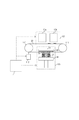
まず、図1を参照して、本発明に係る造形装置の構成について簡単に説明する。図1は、造形装置の全体構成を模式的に示す図である。 First, with reference to FIG. 1, the structure of the modeling apparatus which concerns on this invention is demonstrated easily. FIG. 1 is a diagram schematically illustrating the overall configuration of the modeling apparatus.
造形装置は、概略、制御部(制御ユニットとも称する)U1、層形成部(層形成ユニット)U2、積層部(積層ユニット)U3を有して構成される。 The modeling apparatus generally includes a control unit (also referred to as a control unit) U1, a layer formation unit (layer formation unit) U2, and a lamination unit (lamination unit) U3.
制御部U1は、造形対象物の3次元形状データから複数層のスライスデータ(断面データ)を生成する処理、造形装置の各部の制御などを担うユニットである。 The control unit U1 is a unit that performs processing for generating slice data (cross-section data) of a plurality of layers from the three-dimensional shape data of the modeling target, control of each unit of the modeling apparatus, and the like.
層形成部U2は、第1の材料画像形成部10a、第2の材料画像形成部10b、搬送体20を備えている。第1の材料画像形成部10aでは第1の造形材料からなる像、第2の材料画像形成部10bでは第2の造形材料からなる像を形成することができる。図1では、搬送体20として、複数のローラー110、111に張架された無端ベルトを採用している。例えば、ローラー110は駆動ローラー、ローラー111が従動ローラーで、駆動部112によって駆動ローラー110の動作が制御され、搬送体20の動作も制御される。搬送体20は、ベルト状のものに限定されるものではなく、板状の部材で材料層を担持して搬送する構成であっても構わない。
The layer forming unit U2 includes a first material
スライスデータに基づく制御信号が制御部U1から層形成部U2へと送信されると、層形成部U2では造形対象物の断面に対応した材料層が形成される。具体的には、スライスデータによって指定された造形材料ごとの像(材料像)が、第1の材料画像形成部10aおよび/または第2の材料画像形成部10bにて形成される。第1および第2の材料画像形成部10a、10bで形成された材料像は、搬送体20へと転写されるが、この時2つの材料像の転写位置を制御することで、搬送体20上で造形対象物の一断面に対応する材料層が形成される。転写された材料層は、搬送体20によって積層部U3へと搬送される。
When the control signal based on the slice data is transmitted from the control unit U1 to the layer forming unit U2, a material layer corresponding to the cross section of the modeling target is formed in the layer forming unit U2. Specifically, an image (material image) for each modeling material specified by the slice data is formed by the first material
積層部U3では、層形成部U2で形成される複数の材料層が順に積層され、固着される(以下、積層固着と呼ぶ)ことによって、立体物が作製されるユニットである。 The stacked unit U3 is a unit in which a plurality of material layers formed in the layer forming unit U2 are sequentially stacked and fixed (hereinafter referred to as stacked fixing) to produce a three-dimensional object.
図1に示すように、積層部U3は、対向部材33、ステージ34、弾性部材35を備えている。
As illustrated in FIG. 1, the stacked unit U <b> 3 includes a facing
積層部U3では、搬送体20によって積層位置へと搬送された材料層36を、ステージ34の積層面またはステージ34上で造形中の立体物の積層面と対向部材33との間に挟むことにより、材料層36と積層面とを互いに接触させる。この状態を維持しながら、加圧および加熱が行われ、材料層36が積層面上に積層固着される。積層の際、搬送ベルト20を停止させた状態でステージ34を上下に移動させることにより、材料層36と積層面とを接触させても良いが、搬送体20とステージ34とを同期して動かしながら材料層36と積層面とを接触させても良い。
In the stacking unit U3, the
次に、本発明が解決しようとする課題について詳しく説明する。 Next, problems to be solved by the present invention will be described in detail.
前述したように、材料層は、積層部U3の対向部材33とステージ34との間に挟まれた状態で、加圧および加熱されることにより、搬送体20から積層面の上に転写され積層される。この時、対向部材33の押圧面とステージ34の積層面との平行度が重要となってくる。
As described above, the material layer is transferred from the conveying
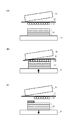
図2は、対向部材33の押圧面とステージ34の積層面とが平行でない場合に、材料層36が造形中の立体物(造形物)37の積層面に転写される際に生じる課題を説明する図で、分かりやすいように誇張して示している。
FIG. 2 illustrates a problem that occurs when the
材料層36が搬送体20によって積層位置に搬送されると、例えば、対向部材33は搬送体20と接触する位置まで下降し、ステージ34が上昇する(図2(a))。ステージ34と対向部材33との距離が縮まり、材料層36と搬送体20を介して両者は接触する。このとき、対向部材33とステージ34の対向面が金属など大きく変形しない材質でできているため、ステージ34と対向部材33は一部しか接触することができない(図2(b))。従って、ステージ34と対向部材33が接触しない領域では、対向部材33からの熱が材料層36に十分に伝わらないため、材料層36が溶融状態になりにくく、積層不良が発生しやすくなる。また、立体物および材料層の一部分しか加圧されず、材料層の加圧されない領域は、造形面へ転写されずに搬送体20上に残り、積層不良となる(図2(c))。
When the
対向部材33の押圧面とステージ34の積層面とを平行に設置できればよいが、実際には、対向部材33とステージ34との対向面の間には、百μm程度の誤差が生じてしまうと考えられる。そこで、特許文献1のように、搬送体20に平行度に応じた適切な膜厚のシリコーンゴムからなる弾性部材を設けると、弾性層によって対向部材33とステージ34との平行度の誤差を吸収することができる。
It is sufficient if the pressing surface of the facing
ところで、搬送体20は、積層位置で材料層が軟化あるいは溶融する温度以上に加熱されるが、積層位置以外では積極的に加熱されている訳ではない。従って、特許文献1のように搬送体20に弾性部材を設けてしまうと、積層の度に搬送体20を所定の温度まで昇温させる必要がある。搬送体20に数百μmの厚さのシリコーンゴムからなる弾性部材が設けられると、積層時に材料層はこのシリコーンゴムを介して加熱されることになるが、シリコーンゴムの熱伝導率は0.2W/m・K程度と低い。そのため、積層の度にシリコーンゴムを所望の温度まで昇温させていると、1回あたりの積層にかかる時間が長くなり、1つの立体物を造形するのに長時間を要することになってしまう。
By the way, although the
そこで、本発明にかかる造形装置では、対向部材33とステージ34との平行度の誤差を吸収するための弾性部材を、対向部材33またはステージ34の少なくとも一方に設ける。弾性部材を対向部材33に設けた場合は、造形している間は対向部材33と共に加熱された状態に置かれるため、積層の度に熱伝導率の低い弾性部材を昇温する必要がない。また、弾性部材をステージ34に設けた場合には、材料層と加熱手段との間に弾性部材が存在しないため、材料層の昇温を妨げない。
Therefore, in the modeling apparatus according to the present invention, an elastic member for absorbing a parallelism error between the facing
図3に本発明に係る造形装置を用いて、材料層36が造形中の立体物(造形物)37の積層面に積層固着される過程の一例を示す。図3では、対向部材33の、ステージ34の積層面と対向する面に弾性部材35が配置されている。図2と同様、対向部材33の押圧面とステージ34の積層面とは平行になっていない。
FIG. 3 shows an example of a process in which the
材料層36が搬送体20によって積層位置に搬送されると、対向部材33は搬送体20と接触する位置まで下降し、ステージ34が上昇する(図3(a))。ステージ34と対向部材33との距離が縮まり、材料層36と搬送ベルト20を介して両者が全面で接触する(図3(b))。図2(b)では、対向部材33とステージ34の対向面が大きく変形しないため、ステージ34と対向部材33の接触面積を広げることができなかった。しかし、図3の場合は弾性部材35が平行度の誤差を吸収するように変形するため、ステージ34と対向部材33を全面接触させることが可能となる。従って、立体物37および材料層36の全面に熱が十分に伝わり、加圧され、材料層36が搬送ベルト20上に残ることなく立体物37へ転写することができる(図3(c))。
When the
弾性部材35は、シート状の部材であるのが特に好ましいが、複数の領域に分割して設けられる構成部材であっても良い。
The
弾性部材35として、JISK6253準拠のタイプDデュロメータで60以下の部材を好適に用いることができる。特に、JISK6253準拠のタイプAデュロメータで90以下の部材が望ましく、JISK6253準拠のタイプAデュロメータで50以下の部材が特に望ましい。例えば、クロロプレンゴム、ニトリルゴム、天然ゴム、エチレン・プロピレンゴム、フッ素ゴム、ウレタンゴム、シリコーンゴムの中から選択される材料や、各ゴム材料を発泡させたゴムスポンジを用いても良い。さらに、これらのゴムやゴムスポンジを複数組み合わせて用いても良い。
As the
弾性部材35の積層面に垂直な方向における厚みは、0.1mm以上2mm以下が好ましい。厚みを0.1mm以上にすることにより対向部材33とステージ34との平行度のずれを吸収することができる。また、弾性部材35の厚みを2mm以下とすることによって、弾性部材35の熱容量が増大するのを抑制し、弾性部材35が対向部材の温度変化に追従しやすくすることができる。その結果、対向部材の温度変化を短時間で材料層に伝えることができる。
The thickness in the direction perpendicular to the laminated surface of the
以下、本発明にかかる実施形態について具体的に説明するが、これらの実施形態で説明する構成を複数組み合わせて採用することもできる。 Hereinafter, embodiments according to the present invention will be specifically described. However, a plurality of configurations described in these embodiments may be employed in combination.
<第1実施形態>
[造形装置の全体構成]
第1実施形態に係る造形装置を備える造形システムの構成を、具体例を挙げて説明する。本実施形態では、粒子状の造形材料を2次元に配置した材料層を積層することによって立体物を作製する方式を用いているが、液状の造形材料を用いて形成した材料層を積層して立体物を作製する方式であってもよい。
<First Embodiment>
[Overall configuration of modeling equipment]
A configuration of a modeling system including the modeling apparatus according to the first embodiment will be described with a specific example. In this embodiment, a method of producing a three-dimensional object by laminating a material layer in which a particulate modeling material is arranged two-dimensionally is used. However, a material layer formed using a liquid modeling material is laminated. A method of producing a three-dimensional object may be used.
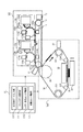
第1実施形態に係る造形装置の構成例を図4に示す。造形装置は、概略、制御部U1、層形成部U2、積層部U3を有して構成される。制御部U1は、造形対象物の3次元形状データから複数層のスライスデータ(断面データ)を生成する処理、造形装置の各部の制御などを担うユニットである。層形成部U2は、電子写真プロセスを利用して造形材料からなる材料層を形成するユニットである。そして、積層部U3は、層形成部U2で形成される複数の材料層を順にステージの上に積層することによって、立体物を形成するユニットである。 The structural example of the modeling apparatus which concerns on 1st Embodiment is shown in FIG. The modeling apparatus includes an outline, a control unit U1, a layer forming unit U2, and a stacking unit U3. The control unit U1 is a unit that performs processing for generating slice data (cross-section data) of a plurality of layers from the three-dimensional shape data of the modeling target, control of each unit of the modeling apparatus, and the like. The layer forming unit U2 is a unit that forms a material layer made of a modeling material using an electrophotographic process. And the lamination | stacking part U3 is a unit which forms a three-dimensional object by laminating | stacking the several material layer formed in the layer formation part U2 on a stage in order.
U1〜U3は、各部を別の筐体に収めてユニット化してもよいし、まとめて1つの筐体の中に収められていてもよい。U1〜U3をユニット化する構成は、立体造形装置の用途、要求性能、使用したい材料、設置スペース、故障などに応じて、ユニットの組み合わせや交換などを容易に行うことができ、装置構成の自由度及び利便性を向上できるという利点がある。一方、U1〜U3をまとめて1つの筐体内に収める構成は、装置全体の小型化、コストダウンなどの利点がある。なお、図4のユニット構成はあくまでも一例であり、他の構成を採用しても構わない。例えば、層形成部U2は、インクジェットプロセスを利用して材料層を形成するものであっても良い。 U1 to U3 may be unitized by storing each part in a separate casing, or may be collectively stored in one casing. The configuration of U1 to U3 as a unit allows easy combination and replacement of units according to the use of the 3D modeling device, required performance, materials to be used, installation space, failure, etc. There is an advantage that the degree and convenience can be improved. On the other hand, the configuration in which U1 to U3 are collectively housed in one housing has advantages such as downsizing of the entire device and cost reduction. Note that the unit configuration in FIG. 4 is merely an example, and other configurations may be adopted. For example, the layer forming unit U2 may form a material layer using an inkjet process.
本実施形態の造形装置では、図1における搬送体20を、第1の搬送体(搬送ベルト)11と第2の搬送体(搬送ベルト)30とで構成している。そして、弾性部材35は、対向部材33と第2搬送ベルト30との間に配置されている。層形成部U2で材料画像が転写される搬送体と、積層部U3で材料層を積層面に転写する搬送体とを分けることにより、積層部の熱が層形成部U2に影響を与えるのを低減することができるという利点がある。
In the modeling apparatus of the present embodiment, the
[制御ユニット]
制御部U1の構成を説明する。制御部U1は、3次元モデルデータ入力部U10、データ生成部U11、層形成制御部U12、積層制御部U13を有している。
[Controller unit]
The configuration of the control unit U1 will be described. The control unit U1 includes a three-dimensional model data input unit U10, a data generation unit U11, a layer formation control unit U12, and a stacking control unit U13.
3次元モデルデータ入力部U10は、外部装置(例えばパソコンなど)から造形対である3次元モデルの3次元形状データや材料情報を受け付ける機能を有している。3次元形状データとして、3次元CAD、3次元モデラー、3次元スキャナなどで作成・出力されたデータを用いることができる。そのファイル形式は問わないが、例えば、STL(StereoLithography)ファイル形式を好ましく用いることができる。 The 3D model data input unit U10 has a function of receiving 3D shape data and material information of a 3D model that is a modeling pair from an external device (for example, a personal computer or the like). As the three-dimensional shape data, data created and output by a three-dimensional CAD, a three-dimensional modeler, a three-dimensional scanner, or the like can be used. Although the file format is not ask | required, for example, an STL (Stereolithography) file format can be used preferably.
データ生成部U11は、3次元形状データで表現された3次元モデルを所定のピッチでスライスして層毎の断面形状を計算し、その断面形状を基に層形成部U2での材料層形成に用いる画像データ(スライスデータと呼ぶ)を生成する機能を有する。画像データは、3次元モデルの材料情報と紐付けされており、どの造形材料をどのように配置するかを、層形成部U2に与えることができる。さらに、データ生成部U11は、3次元形状データ又はスライスデータを解析して、オーバーハング部(直下が空間となる部分)の有無を判断し、必要に応じてサポート材料を配置するためのデータを含むスライスデータを生成する。 The data generation unit U11 calculates a cross-sectional shape for each layer by slicing a three-dimensional model represented by the three-dimensional shape data at a predetermined pitch, and forms a material layer in the layer forming unit U2 based on the cross-sectional shape. It has a function of generating image data to be used (referred to as slice data). The image data is associated with the material information of the three-dimensional model, and it can be given to the layer forming unit U2 which modeling material is to be arranged. Further, the data generation unit U11 analyzes the three-dimensional shape data or slice data, determines the presence or absence of an overhang portion (a portion where the space immediately below is a space), and outputs data for arranging the support material as necessary. Generate the slice data that contains it.
3次元モデルデータ入力部U10、および、データ生成部U11は、層形成制御部U12で材料層を形成するためのデータが入手できるのであれば、造形装置が備えていなくても構わない。例えば、制御部U1が、3次元モデルデータ入力部U10とデータ生成部U11の代わりに受信部を備えており、ネットワーク回線を介して外部で生成されたスライスデータを取得する構成であってもよい。 The three-dimensional model data input unit U10 and the data generation unit U11 may not include the modeling apparatus as long as data for forming a material layer can be obtained by the layer formation control unit U12. For example, the control unit U1 may include a receiving unit instead of the three-dimensional model data input unit U10 and the data generation unit U11, and acquire slice data generated outside via a network line. .
詳しくは後述するが、本実施形態の層形成ユニットU2は複数種類の材料を用いた材料層の形成が可能である。そのため、スライスデータは、それぞれの材料の像に対応するデータを含んでいる。スライスデータのファイル形式としては、例えば、多値の画像データ(各値が材料の種類を表す)やマルチプレーンの画像データ(各プレーンが材料の種類に対応する)を用いることができる。 As will be described in detail later, the layer forming unit U2 of the present embodiment can form a material layer using a plurality of types of materials. Therefore, the slice data includes data corresponding to each material image. As the file format of the slice data, for example, multi-value image data (each value represents a material type) or multi-plane image data (each plane corresponds to a material type) can be used.
層形成制御部U12は、スライスデータに基づいて、層形成部U2における材料層形成プロセスを制御する機能を有する。また、積層制御部U13は、積層部U3における積層プロセスを制御する機能を有する。各部での具体的な制御内容については後述する。 The layer formation control unit U12 has a function of controlling the material layer formation process in the layer formation unit U2 based on the slice data. Further, the stacking control unit U13 has a function of controlling the stacking process in the stacking unit U3. Specific control contents in each part will be described later.
また、図示しないが、制御ユニットU1は、操作部、表示部、記憶部を備えている。操作部は、ユーザからの指示を受け付ける機能である。例えば、電源のオン/オフ、装置の各種設定、動作指示などの入力が可能である。表示部は、ユーザへの情報提示を行う機能を有しており、例えば、各種設定画面、エラーメッセージ、動作状況などの提示が可能である。記憶部は、3次元形状データ、スライスデータ、各種設定値などを記憶する機能を有している。 Although not shown, the control unit U1 includes an operation unit, a display unit, and a storage unit. The operation unit is a function that receives an instruction from the user. For example, power on / off, various device settings, operation instructions, and the like can be input. The display unit has a function of presenting information to the user, and can present various setting screens, error messages, operating conditions, and the like, for example. The storage unit has a function of storing three-dimensional shape data, slice data, various setting values, and the like.
制御部U1は、ハードウエア的には、CPU(中央演算処理装置)、メモリ、補助記憶装置(ハードディスク、フラッシュメモリなど)、入力デバイス、表示デバイス、各種I/Fを具備したコンピュータにより構成することができる。上述した各機能U10〜U13は、補助記憶装置などに格納されたプログラムをCPUが読み込んで実行し、必要なデバイスを制御することで実現されるものである。ただし、上述した機能のうちの一部又は全部をASICやFPGAなどの回路で構成したり、あるいは、クラウドコンピューティングやグリッドコンピューティングなどの技術を利用して他のコンピュータに実行させてもよい。 The control unit U1 is configured in hardware by a computer having a CPU (Central Processing Unit), a memory, an auxiliary storage device (hard disk, flash memory, etc.), an input device, a display device, and various I / Fs. Can do. Each of the functions U10 to U13 described above is realized by the CPU reading and executing a program stored in an auxiliary storage device or the like and controlling necessary devices. However, some or all of the functions described above may be configured by a circuit such as an ASIC or FPGA, or may be executed by another computer using a technique such as cloud computing or grid computing.
[層形成部]
層形成部U2は、電子写真プロセスを利用して造形材料からなる材料画像を形成するユニットである。電子写真プロセスとは、感光体を帯電し、露光によって潜像を形成し、現像剤粒子を付着させて現像剤像を形成するという一連のプロセスによって、所望の像を形成する手法である。
[Layer formation part]
The layer forming unit U2 is a unit that forms a material image made of a modeling material using an electrophotographic process. The electrophotographic process is a technique for forming a desired image by a series of processes in which a photoreceptor is charged, a latent image is formed by exposure, and developer particles are attached to form a developer image.
図4に示すように、層形成部U2は、第1の材料画像形成部10a、第2の材料画像形成部10b、第1の搬送ベルト11、ベルトクリーニング装置12、画像検知センサー13を備えている。第1の材料画像形成部10aは、第1の造形材料Maを用いて材料層を形成するための材料画像形成手段であり、像担持体100a、帯電装置101a、露光装置102a、現像装置103a、転写装置104a、クリーニング装置105aを有する。第2の材料画像形成部10bも第1の材料画像形成部10aと同様の構成を有している。
As shown in FIG. 4, the layer forming unit U2 includes a first material
これらの材料画像形成部10a、10bは第1の搬送ベルト11の表面に沿って配置されている。なお、図4では、構造材料の材料画像形成部10aを搬送方向上流側に配置しているが、材料画像形成部の配置順は限定されない。また、材料画像形成部の数は2つより多くてもよく、用いる造形材料の種類に応じて適宜増やすことができる。例えば、4つの材料画像形成部を設けると、4種類の構造材料で像形成を行ったり、3種類の構造材料と1種類のサポート材料とで像形成を行ったりすることができる。材質、色、固さなど物性が異なる複数種類の材料を組み合わせることで、生成する立体造形物のバリエーションが豊富になる。このような拡張性に優れる点も、電子写真プロセスを利用した立体造形装置の利点の一つといえる。
These material
以下、層形成部U2の各部の構成について詳しく説明する。ただし、材料画像形成部10a〜10dに共通する説明の中では、構成部材の参照符号の添え字a〜dを省略し、材料画像形成部10、像担持体100などと記載する。
Hereinafter, the configuration of each part of the layer forming unit U2 will be described in detail. However, in the description common to the material
(像担持体)
像担持体100は、静電潜像を担持するための部材である。ここでは、アルミニウムなどの金属製シリンダーの外周面に光導電性を有する感光体層が形成された感光体ドラムが用いられる。感光体としては、有機感光体(OPC)、アモルファスシリコン感光体、セレン感光体などを用いることができ、立体造形装置の用途や要求性能に応じて感光体の種類を適宜選択すればよい。像担持体100は、不図示の枠体に回転自在に支持されており、像形成時には不図示のモーターによって図中の時計周りに一定速度で回転する。
(Image carrier)
The
(帯電装置)
帯電装置101は、像担持体100の表面を一様に帯電させるための帯電手段である。本実施形態ではコロナ放電による非接触帯電方式を用いるが、帯電ローラーを像担持体100の表面に接触させるローラー帯電方式など他の帯電方式を用いても構わない。
(Charging device)
The charging device 101 is charging means for uniformly charging the surface of the
(露光装置)
露光装置102は、画像情報(スライスデータ)に従って像担持体100を露光し、像担持体100の表面上に静電潜像を形成する露光手段である。露光装置102は、例えば、半導体レーザや発光ダイオードなどの光源と、高速回転するポリゴンミラーからなる走査機構と、結像レンズなどの光学部材とを有して構成される。
(Exposure equipment)
The
(現像装置)
現像装置103は、現像剤(ここでは、構造材料又はサポート材料の粒子)を像担持体100に供給することで、静電潜像を可視化する現像手段である(本明細書では、現像剤によって可視化された像を材料画像と称す)。現像装置103は、2次元のプリンタに用いられる現像装置と同様の構成を採用することができる。
(Developer)
The developing device 103 is a developing unit that visualizes an electrostatic latent image by supplying a developer (here, particles of a structural material or a support material) to the image carrier 100 (in this specification, by a developer). Visualized image is called material image). The developing device 103 can employ the same configuration as the developing device used in a two-dimensional printer.
現像装置103は、いわゆる現像カートリッジの構造をとり、画像形成ユニットU2に対し着脱自在に設けられているのが好ましい。カートリッジの交換により現像剤(構造材料、サポート材料)の補充・変更が容易にできるからである。あるいは、像担持体100、現像装置103、クリーニング装置105などを一体のカートリッジとし(いわゆるプロセスカートリッジ)、像担持体自体の交換を可能にしてもよい。構造材料やサポート材料の種類、固さ、粒径により像担持体100の摩耗や寿命が特に問題となる場合には、プロセスカートリッジ構成の方が実用性・利便性に優れる。
The developing device 103 has a so-called developing cartridge structure, and is preferably provided detachably with respect to the image forming unit U2. This is because the developer (structural material, support material) can be easily replenished and changed by exchanging the cartridge. Alternatively, the
(転写装置)
転写装置104は、像担持体100上の材料画像を第1の搬送ベルト11の表面上へと転写させる転写手段である。転写装置104は、第1の搬送ベルト11を挟んで像担持体100の反対側に配置されており、像担持体100上の材料画像と逆極性の電圧を印加することで、静電的に材料画像を搬送ベルト11側へと転写させる。像担持体100から第1の搬送ベルト11への転写を1次転写とも称す。図4の造形装置ではコロナ放電を利用した転写方式を用いているが、ローラー転写方式や、静電転写方式以外の転写方式を採用することもできる。
(Transfer device)
The transfer device 104 is a transfer unit that transfers the material image on the
(クリーニング装置)
クリーニング装置105は、転写されずに像担持体100上に残った現像剤粒子を回収し、像担持体100の表面を清浄する手段である。図4では、像担持体100に対しカウンター方向に当接させたクリーニングブレードによって現像剤粒子を掻き落とすブレード方式のクリーニング装置105が採用されているが、ブラシ方式や静電吸着方式のクリーニング装置を用いてもよい。
(Cleaning device)
The cleaning device 105 is a unit that collects developer particles remaining on the
(第1の搬送ベルト)
第1の搬送ベルト11は、各材料画像形成部10で形成された材料画像が転写される担持体である。まず、第1の搬送ベルト11の搬送方向において上流側の材料画像形成部10aから構造材料の材料画像が転写される。その後、先に第1の搬送ベルト11に転写された材料画像に対する配置を考慮して、下流側の材料画像形成部10bからサポート材料の材料画像を転写することで、第1の搬送ベルト11の表面上に1枚の材料層が形成される。
(First conveyor belt)
The
第1の搬送ベルト11は、樹脂、ポリイミドなどの材料からなる無端ベルトであり、図4に示すように、複数のローラー110、111に張架されている。なお、ローラー110、111の他にテンションローラーを設け、第1の搬送ベルト11のテンションを調整できるようにしてもよい。ローラー110、111のうち少なくとも一方は駆動ローラーであり、像形成時には不図示のモーターの駆動力によって第1の搬送ベルト11を図中反時計周りに回転させる。また、ローラー110は、積層ユニットU3の2次転写ローラー31との間で2次転写部を形成するローラーである。
The
(ベルトクリーニング装置)
ベルトクリーニング装置12は、第1の搬送ベルト11の表面に付着した材料をクリーニングする手段である。本実施形態では、第1の搬送ベルト11に対しカウンター方向に当接させたクリーニングブレードによって材料を掻き落とすブレード方式のクリーニング装置を採用するが、ブラシ方式や静電吸着方式のクリーニング装置を用いてもよい。
(Belt cleaning device)
The
(画像検知センサー)
画像検知センサー13は、第1の搬送ベルト11の表面に担持された材料画像を読み取る検知手段である。画像検知センサー13の検知結果は、材料画像の位置合わせ、後段の積層部U3とのタイミング制御、材料画像の異常検知(所望の像でない、像が無い、厚みのばらつきが大きい、像の位置ずれが大きいなど)などに利用される。
(Image detection sensor)
The image detection sensor 13 is a detection unit that reads a material image carried on the surface of the
[積層部]
次に、積層部U3の構成を説明する。積層部U3は、層形成部U2で形成された材料層を第1の持搬送ベルト11から受け取り、これを順に積層し固着することによって、立体物を作製するユニットである。
[Laminated part]
Next, the configuration of the stacked unit U3 will be described. The stacking unit U3 is a unit that produces a three-dimensional object by receiving the material layer formed by the layer forming unit U2 from the first holding and conveying
図4に示すように、積層部U3は、第2の搬送ベルト30、2次転写ローラー31、画像検知センサー32、対向部材33、ステージ34、弾性部材35を備えている。以下、積層部U3の各部の構成について詳しく説明する。
As illustrated in FIG. 4, the stacking unit U <b> 3 includes a
(第2の搬送ベルト)
第2の搬送ベルト30は、材料層を第1の搬送ベルト11から受け取り、その材料層を積層位置まで担持搬送する。積層位置とは、材料層の積層(積層面への積み上げ)が行われる位置であり、図4の構成では、第2の搬送ベルト30が対向部材33と弾性部材35およびステージ34とで挟まれる部分が積層位置に該当する。
(Second conveyor belt)
The
第2の搬送ベルト30には、樹脂、ポリイミドなどの材料からなる無端ベルトや、金属シートの上に中抵抗層(体積抵抗率1×10⁶〜1013Ω・cm)が設けられた構成の無端ベルトを用いることができる。搬送ベルトが金属を含んでいる場合、積層時の温度制御を比較的短時間で行うことができるため、好ましい。
The
第2の搬送ベルト30は、2次転写ローラー31、及び、複数のローラー301、302、303、304に張架されている。ローラー31、301、302のうち少なくともいずれかが駆動ローラーであり、不図示のモーターの駆動力によって第2の搬送ベルト30を図中時計周りに回転させることができる。
The
(2次転写ローラー)
2次転写ローラー31は、第1の搬送ベルト11から第2の搬送ベルト30へと、材料層を転写させるための転写手段である。2次転写ローラー31は、層形成部U2の対向ローラー110との間で第1の搬送ベルト11及び第2の搬送ベルト30を挟み込むことで、両者のベルト間に2次転写ニップを形成する。そして、不図示の電源により2次転写ローラー31に材料画像とは逆極性のバイアスを印加することで、材料層を第2の搬送ベルト30へと転写させることができる。
(Secondary transfer roller)
The secondary transfer roller 31 is a transfer unit for transferring the material layer from the
(画像検知センサー)
画像検知センサー32は、第2の搬送ベルト30の表面に担持された材料層を読み取る検知手段である。画像検知センサー32の検知結果は、材料層の位置合わせ、積層位置への搬送タイミング制御などに利用される。
(Image detection sensor)
The
(対向部材)
対向部材33は、積層位置に搬送された材料層にステージ34または造形物を押し当て圧力を加えるための押圧部材である。対向部材33は、第2の搬送ベルト30を挟んでステージ34と対向する位置に配置され、ステージ34に対向する押圧面は平面となっている。ただし、対向部材33の押圧面は必ずしも平面である必要はなく、例えば、第2の搬送ベルト30の搬送方向に対して垂直な回転軸を有するローラー形状の部材を採用することができる。対向部材33がローラー形状を有する場合、回転軸と積層面とが平行でなければ、押圧面が平面の対向部材33と同様の課題が生じる。
(Opposing member)
The facing
また、対向部材33は、材料層の温度を制御する温度制御手段を備えており、材料層を軟化温度以上に加熱することができる。温度制御手段には、例えばセラミックヒーター、ハロゲンヒーターなどの温度制御が可能な加熱手段を用いることができる。また、加熱手段だけでなく、チラーなどを用いて放熱ないし冷却により材料層の温度を積極的に低下させる冷却手段を設けてもよい。
Moreover, the opposing
(ステージ)
ステージ34は、材料層が積層され立体物が作製される平面台である。ステージ34は、不図示のアクチュエータによって、材料層の積層方向に移動可能となっている。積層位置まで担持搬送された材料層を、第2の搬送ベルトごと弾性部材35と積層面との間で挟み込み、加熱および加圧を行うことで、材料層を第2の搬送ベルト30からステージ34へと転写させる。1層目の材料層はステージ34の上に直接転写され、2層目以降の材料層はステージ34上の作製中の立体物の上に積み上げられていく。ステージ34の上か作製中の立体物の上かにかからず、材料層が積層される面と積層面と称する。
(stage)
The
(弾性部材)
本実施形態では、弾性部材35は対向部材33の加圧面(ステージの積層面と対向する面)側に配置されている。このような構成によれば、図2で説明したように、造形中の立体物と材料層と第2の搬送ベルトとを重ねた状態で、これらを対向部材33の弾性部材35が設けられた面に押し当てて加圧される。すると、造形物の積層面と対向部材33の加圧面とが平行でない場合でも、弾性部材35の収縮作用によってステージ34と対向部材33の全面が接触するため、材料画像領域の全域が加圧され、積層固着に必要な熱が十分に伝わるようになる。その結果、積層不良の発生を抑制することが可能となる。
(Elastic member)
In the present embodiment, the
前述したように、対向部材33がローラー形状を有する場合、押圧面となるローラーの周面に沿って弾性部材を配置すればよい。
As described above, when the facing
[造形装置の動作]
次に、上記構成を有する造形装置を用いて立体物を作製する際の造形動作について説明する。ここでは、既に3次元モデルのスライスデータが取得されたものとして説明する。図5は、本実施形態の造形装置の動作シーケンスを示すフローチャートである。
[Operation of modeling equipment]
Next, a modeling operation when producing a three-dimensional object using the modeling apparatus having the above configuration will be described. Here, a description will be given assuming that slice data of a three-dimensional model has already been acquired. FIG. 5 is a flowchart showing an operation sequence of the modeling apparatus of this embodiment.
まず、制御部U1は、各材料画像形成部10の像担持体100、第1の搬送ベルト11、及び、第2の搬送ベルト30が同じ外周速度(プロセス速度)で同期して回転するよう、モーター等の駆動源を制御する。
First, the control unit U1 causes the
回転速度が安定した後、上流側の材料画像形成部10aにて、公知の電子写真プロセスを用いて、第1の造形材料からなる材料画像を形成する(S501)。この材料画像は、転写装置104aによって第1の搬送ベルト11上へと1次転写される。
After the rotation speed is stabilized, a material image made of the first modeling material is formed by using a known electrophotographic process in the upstream material
また、制御部U1からの制御信号を受け、材料画像形成部10aでの像形成開始から所定の時間をおいて、材料画像形成部10bで、材料画像形成部10aと同様にして第2の造形材料からなる材料画像の形成が開始される(S502)。この時、材料画像形成部10a、10bにおける像形成開始の時間差を調整することにより、それぞれの材料画像形成部で別々に形成された材料画像が第1の搬送ベルト11上で位置合わせして配置され、1層分の材料層が形成される(S503)。第1の造形材料として、3次元モデルを構成する構造材料、第2の造形材料としてサポート材料を用いる例が考えられる。第2の造形材料の配置が必要の無い材料層の場合には、材料画像形成部10bでの像形成は行われず、第1の造形材料の材料画像のみで材料層が形成される。その後、材料層は第1の搬送ベルト11によって積層部U3へと搬送される。
In response to a control signal from the control unit U1, the material image forming unit 10b performs the second modeling in the same manner as the material
上記のように材料層の形成動作が行われている間、積層部U3の第2の搬送ベルト30は第1の搬送ベルト11に接触した状態で、同じ外周速度(プロセス速度)で同期回転している。そして、第1の搬送ベルト11上の材料層の前端が2次転写ニップに到達するタイミングに合わせて、制御部U1が2次転写ローラー31に所定の転写バイアスを印加し、材料層を第2の搬送ベルト30へと転写させる(S506)。
While the material layer forming operation is performed as described above, the
第2の搬送ベルト30は同じプロセス速度のまま回転を続け、材料層を図4の矢印方向に搬送する。そして、画像検知センサー32がベルト上の材料層の位置を検知すると、制御部U1はその検知結果に基づいて材料層を所定の積層位置まで搬送させる(S508)。材料層が積層位置に到達するタイミングで、制御部U1は第2の搬送ベルト30を停止させ、材料層を積層位置に位置決めする(S509)。その後、制御部U1はステージ34を上昇させてベルト面に近づけ、ステージ面又はステージ面上の造形物の上面を第2の搬送ベルト30上の材料層に接触させ、対向部材33との間で挟み込むことで造形物と材料層とを加圧する(S510)。この状態を維持して、制御部U1は、所定の温度制御シーケンスにしたがって、対向部材33が備える昇温手段の温度を制御する。具体的には、最初に、第1の目標温度まで対向部材33を加熱する第1のモードを所定時間行って、材料層の粒子材料を熱溶融させる(S511)。すなわち、第1のモードにおいては、対向部材33による材料層の加熱を行う。これにより材料層が軟化し、シート状の材料画像とステージ面又は立体造形物上面とが密着する。このとき、立体造形物の積層面と対向部材33の加圧面とが平行でない場合でも、弾性部材35の収縮作用によって、立体物と材料層間の圧力むらおよび温度むらが軽減され、圧力不足および熱不足によって発生する積層不良を抑制することができる。その後、第1の目標温度よりも低い第2の目標温度に対向部材33を制御する第2のモードを所定時間行い、軟化した材料層を固化させる(S512)。
The
なお、第1のモード及び第2のモードにおいては、温度の制御域が広すぎると、温度制御を安定化させるのに時間がかかり、積層プロセス時間が必要以上にかかってしまう。それゆえ、第1の目標温度の制御域は、材料層を構成する各材料の融点もしくはガラス転移点のうち最も高い温度を下限温度とし、上限温度は下限温度の+50℃程度に設定するとよい。同じように、第2の目標温度の制御域は、材料層を構成する各材料の結晶化温度もしくは非晶質材のガラス転移点のうち最も低い温度を上限温度とし、下限温度は上限温度の−50℃程度に設定するとよい。第2のモード終了後、制御部U1はステージ34を下降させ、対向部材33から遠ざける(S513)。
In the first mode and the second mode, if the temperature control range is too wide, it takes time to stabilize the temperature control, and the stacking process time takes more than necessary. Therefore, in the control range of the first target temperature, the highest temperature among the melting points or glass transition points of the materials constituting the material layer is set as the lower limit temperature, and the upper limit temperature is preferably set to about + 50 ° C. of the lower limit temperature. Similarly, in the control range of the second target temperature, the lowest temperature of the crystallization temperature of each material constituting the material layer or the glass transition point of the amorphous material is the upper limit temperature, and the lower limit temperature is the upper limit temperature. It is good to set at about -50 ° C. After the end of the second mode, the control unit U1 lowers the
材料層全体が第2の搬送ベルト30の表面から積層面へと転写された後、必要数の材料層の積層が終了したかどうかの判断が行われ(S514)、必要数に達している場合は積層動作は終了され、必要数に達していない場合は次層の材料画像形成プロセスの実行が開始される(S501〜)。
After the entire material layer has been transferred from the surface of the
以上の工程を必要回数繰り返すことで、ステージ34上に所望の立体物が形成される。立体物の完成後、ステージ34から立体物を取り外し、サポート材料を除去することで、3次元モデルに対応した最終立体物(物品)を得ることができる。なお、サポート材料の除去後、更に、所定の処理(例えば、クリーニング、組立等)を立体物に対して行うことで、最終立体物(物品)を製造してもよい。
A desired three-dimensional object is formed on the
以上説明したように、本実施形態にかかる造形装置を用いて造形を行えば、対向部材33の加圧面とステージ34上の積層面が平行でない場合であっても、弾性部材35の収縮作用によって積層不良を抑制することができる。その結果、造形精度の高い立体物を作製することが可能となる。
As described above, if modeling is performed using the modeling apparatus according to the present embodiment, the
<第2実施形態>
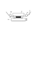
本実施形態に係る立体造形装置の積層位置における構成の概略を図6に示す。本実施形態は、弾性部材35を、ステージ34の積層面表面に配置している点で第1実施形態と異なる他は、第1の実施形態と同様である。
Second Embodiment
FIG. 6 shows an outline of the configuration at the stacking position of the three-dimensional modeling apparatus according to this embodiment. The present embodiment is the same as the first embodiment except that the
本実施形態も、立体物および材料層を第2の搬送ベルト30および対向部材33に押し当てて加圧および加熱する際に、弾性部材35の収縮作用によって、材料層と積層面との間に生じる圧力むら及び温度むらを軽減することができる。その結果、対向部材33の加圧面と立体物の積層面とが平行でない場合であっても、積層不良を抑制することが可能となる。
Also in this embodiment, when the solid object and the material layer are pressed against the second conveying
さらに、本実施形態は、第1の実施形態に比べ、加熱手段を備える対向部材33と材料層との間に弾性部材35が存在しないため、材料層の温度制御をより短時間で行うことができるため好ましい。
Further, in the present embodiment, since the
<第3実施形態>
造形完了後の立体物をステージ34から取り外しやすくするため、ステージの積層面側に取り外し容易な造形プレートを設けてから造形する方法がある。
<Third Embodiment>
In order to make it easy to remove the three-dimensional object after the modeling from the
造形プレートには種々の材質のものを採用することができるが、造形プレート自体が弾性部材として機能する弾性率を有している場合は、第2の実施形態に含まれる。そこで、本実施形態では、造形プレートに金属などの弾性率の高い材質からなる板状の部材を用いる場合について説明する。 Various materials can be used for the modeling plate. However, when the modeling plate itself has an elastic modulus that functions as an elastic member, it is included in the second embodiment. Therefore, in the present embodiment, a case where a plate-like member made of a material having a high elastic modulus such as a metal is used for the modeling plate will be described.
弾性率の高い造形プレートを用いる場合、造形プレートの対向部材と対向する側の面に弾性部材を配置する形態と、造形プレートとステージとの間に弾性部材を配置する形態とが考えられる。 When using a modeling plate with a high elastic modulus, a mode in which the elastic member is arranged on the surface of the modeling plate facing the facing member and a mode in which the elastic member is arranged between the modeling plate and the stage are conceivable.
まず、造形プレートの対向部材と対向する側の面に弾性部材を配置する形態は、弾性部材を備える造形プレートをステージの上に設置することで実現することができ、図6と同等の構成と効果を得ることができるため、詳細な説明は省略する。 First, the form in which the elastic member is arranged on the surface of the modeling plate facing the facing member can be realized by installing the modeling plate provided with the elastic member on the stage, and has the same configuration as FIG. Since an effect can be obtained, detailed description is omitted.
次に、造形プレートとステージとの間に弾性部材が設けられた形態を説明する。かかる造形装置の積層位置における構成を図7に示す。取り外しが可能な造形プレート40と、ステージとの間に弾性部材35が配置されている点で第1実施形態と異なっているが、その他は第1の実施形態と同様である。
Next, a mode in which an elastic member is provided between the modeling plate and the stage will be described. The configuration of the modeling apparatus at the stacking position is shown in FIG. Although it differs from 1st Embodiment by the point by which the
対向部材33の加圧面と立体物の積層面とが平行でない場合に、対向部材33と材料層と第2搬送ベルト30と造形プレート40とが互いに接触し始めると、その力を受けて弾性部35が変形を始める。つまり、弾性部材35の収縮作用によって、材料層全体を積層面に接触させることができる。その結果、対向部材33の加圧面と立体物の積層面とが平行でない場合であっても、積層不良を低減して造形を行うことが可能となる。この弾性部材35として、造形プレート40とステージ34との間に複数のバネを配置する構成を採用することもできる。
When the pressing surface of the opposing
造形プレート40は、弾性部材35の変形を制限しない形でステージに設置する。例えば、弾性部材35とステージ34の対向部材33に対向する面とを接着剤で固定し、造形プレート40を適度な粘着力を有する材料で弾性部材35に固定するとよい。他に、造形が行われる積層面を有する第1プレートとステージに固定するための第2プレートとを有し、第1プレートと第2プレートとの間に弾性部材35が挟まれている構成の造形プレート40を用いてもよい。第2プレートが、ネジや嵌合構造によってステージに着脱可能に固定できる構造を有し、弾性部材35は、第1プレートと第2プレートそれぞれとの接触面が接着剤で固定されている構成が好ましい。
The
次に、造形プレートが弾性部材を有さない形態について説明する。造形プレートが弾性部材を備えていない場合は、そのままでは積層不良が生じてしまうため、第1実施形態と組み合わせるか、第2実施形態を組み合わせるとよい。弾性部材を有さない造形プレートと第2の実施形態を組み合わせると、図7と同等の構成を実現することができる。 Next, the form in which the modeling plate does not have an elastic member will be described. If the modeling plate does not include an elastic member, a stacking failure may occur as it is, and therefore, it may be combined with the first embodiment or the second embodiment. When the modeling plate having no elastic member is combined with the second embodiment, a configuration equivalent to that in FIG. 7 can be realized.
以上説明したように、造形プレートを用いる場合、造形プレートの対向部材と対向する側の面に弾性部材を配置するか、弾性部材を備える造形プレートをステージの上に設置すると良い。このような構成により、積層不良の発生を抑制すると共に、造形完了後の立体物をステージ34から取り外しやすくなり、立体物1つあたりの造形時間を短縮することができる。
As described above, when a modeling plate is used, it is preferable to arrange an elastic member on the surface of the modeling plate facing the opposing member, or to install a modeling plate having an elastic member on the stage. With such a configuration, it is possible to suppress the occurrence of stacking faults and to easily remove the three-dimensional object after modeling from the
U2 画像形成部
10a、10b 材料画像形成部
11 第1の搬送ベルト
20 搬送体(搬送ベルト)
U3 積層部
30 第2の搬送ベルト
33 対向部材
34 ステージ
35 弾性部材
36 材料層
37 立体物
U2
Claims (13)
前記材料層を形成する層形成部と、
前記材料層を積層面の上に積層する積層部と、
を備えており、
前記積層部が、前記材料層が積層されるステージと、
前記ステージとの間で前記材料層を挟んで加圧する対向部材と、
弾性部材と、
を備えており、
前記弾性部材が、前記ステージまたは前記対向部材に設けられており、
前記ステージまたは前記対向部材が、前記弾性部材を介して前記材料層を加圧することを特徴とする造形装置。 A modeling apparatus for producing a three-dimensional object by stacking material layers formed based on slice data of a three-dimensional model,
A layer forming part for forming the material layer;
A laminating part for laminating the material layer on the laminating surface;
With
The stacking section is a stage on which the material layer is stacked;
An opposing member that pressurizes the material layer with the stage interposed therebetween;
An elastic member;
With
The elastic member is provided on the stage or the opposing member;
The modeling apparatus, wherein the stage or the opposing member pressurizes the material layer via the elastic member.
Priority Applications (1)
| Application Number | Priority Date | Filing Date | Title |
|---|---|---|---|
| JP2016148936A JP2018016005A (en) | 2016-07-28 | 2016-07-28 | Molding apparatus |
Applications Claiming Priority (1)
| Application Number | Priority Date | Filing Date | Title |
|---|---|---|---|
| JP2016148936A JP2018016005A (en) | 2016-07-28 | 2016-07-28 | Molding apparatus |
Publications (2)
| Publication Number | Publication Date |
|---|---|
| JP2018016005A true JP2018016005A (en) | 2018-02-01 |
| JP2018016005A5 JP2018016005A5 (en) | 2019-08-29 |
Family
ID=61075006
Family Applications (1)
| Application Number | Title | Priority Date | Filing Date |
|---|---|---|---|
| JP2016148936A Pending JP2018016005A (en) | 2016-07-28 | 2016-07-28 | Molding apparatus |
Country Status (1)
| Country | Link |
|---|---|
| JP (1) | JP2018016005A (en) |
Cited By (3)
| Publication number | Priority date | Publication date | Assignee | Title |
|---|---|---|---|---|
| EP3520984A1 (en) | 2018-01-31 | 2019-08-07 | Sumitomo Heavy Industries, LTD. | Injection molding method and mold unit |
| JP2021509095A (en) * | 2017-12-29 | 2021-03-18 | エボルブ アディティブ ソリューションズ, インコーポレイテッド | Compliant melt transfer rollers for additive manufacturing systems based on selective lamination |
| CN114103096A (en) * | 2020-04-27 | 2022-03-01 | 精工爱普生株式会社 | Three-dimensional modeling device and method for manufacturing three-dimensional modeled object |
Citations (1)
| Publication number | Priority date | Publication date | Assignee | Title |
|---|---|---|---|---|
| JP2016026928A (en) * | 2014-07-03 | 2016-02-18 | キヤノン株式会社 | Three-dimensional object modeling apparatus, recording apparatus, transfer method, pressing member for transfer, and transfer body |
-
2016
- 2016-07-28 JP JP2016148936A patent/JP2018016005A/en active Pending
Patent Citations (1)
| Publication number | Priority date | Publication date | Assignee | Title |
|---|---|---|---|---|
| JP2016026928A (en) * | 2014-07-03 | 2016-02-18 | キヤノン株式会社 | Three-dimensional object modeling apparatus, recording apparatus, transfer method, pressing member for transfer, and transfer body |
Cited By (5)
| Publication number | Priority date | Publication date | Assignee | Title |
|---|---|---|---|---|
| JP2021509095A (en) * | 2017-12-29 | 2021-03-18 | エボルブ アディティブ ソリューションズ, インコーポレイテッド | Compliant melt transfer rollers for additive manufacturing systems based on selective lamination |
| JP7348913B2 (en) | 2017-12-29 | 2023-09-21 | エボルブ アディティブ ソリューションズ, インコーポレイテッド | Compliant Fused Transfer Roller for Additive Manufacturing Systems Based on Selective Lamination |
| EP3520984A1 (en) | 2018-01-31 | 2019-08-07 | Sumitomo Heavy Industries, LTD. | Injection molding method and mold unit |
| CN114103096A (en) * | 2020-04-27 | 2022-03-01 | 精工爱普生株式会社 | Three-dimensional modeling device and method for manufacturing three-dimensional modeled object |
| CN114103096B (en) * | 2020-04-27 | 2024-01-26 | 精工爱普生株式会社 | Three-dimensional modeling apparatus and method for manufacturing three-dimensional modeling object |
Similar Documents
| Publication | Publication Date | Title |
|---|---|---|
| US10357956B2 (en) | Shaping apparatus and shaping method | |
| WO2016084350A1 (en) | Forming apparatus, three-dimensional forming method, and object formed by using the method | |
| US11052609B2 (en) | Molding system, data processing device for generating molding data, and method of manufacturing three-dimensional object | |
| JP2018016005A (en) | Molding apparatus | |
| JP2017105088A (en) | Molding apparatus | |
| JP2014164074A (en) | Fixing device | |
| WO2016084351A1 (en) | Method and apparatus for forming stereoscopic object | |
| WO2016084367A1 (en) | Three-dimensional shaping apparatus and three-dimensional shaped article manufacturing method | |
| WO2016084348A1 (en) | Three-dimensional modeling apparatus, three-dimensional modeling method, and article manufacturing method | |
| JP5621445B2 (en) | Gloss imparting apparatus and image forming apparatus | |
| JP2016107630A (en) | Molding device, production method, and molded object molded by the same | |
| WO2016084913A1 (en) | Shaping device and method for fabricating three-dimensional object | |
| JP2018176428A (en) | Three-dimensional shaping apparatus | |
| JP2016107634A (en) | Molding device and three-dimensional object production method | |
| JP2018020474A (en) | Molding device and molding method | |
| JP5810689B2 (en) | Fixing apparatus and image forming apparatus | |
| US20190056688A1 (en) | Forming apparatus, and manufacturing method of three-dimensional object | |
| JP6700958B2 (en) | Modeling apparatus and modeling method | |
| JP2016107629A (en) | Three-dimensional molding apparatus and method for manufacturing three-dimensional molded object | |
| JP2012168320A (en) | Fixing device and image forming apparatus with the same | |
| JP2017177813A (en) | Molding apparatus | |
| JP6758899B2 (en) | Modeling equipment | |
| JP2013167678A (en) | Endless belt driving device and image forming apparatus having the same | |
| JP2015156004A (en) | image forming apparatus | |
| WO2017110074A1 (en) | Molding system, data processing device for generating molding data, and method of manufacturing three-dimensional object |
Legal Events
| Date | Code | Title | Description |
|---|---|---|---|
| A521 | Written amendment |
Free format text: JAPANESE INTERMEDIATE CODE: A523 Effective date: 20190719 |
|
| A621 | Written request for application examination |
Free format text: JAPANESE INTERMEDIATE CODE: A621 Effective date: 20190719 |
|
| A977 | Report on retrieval |
Free format text: JAPANESE INTERMEDIATE CODE: A971007 Effective date: 20200707 |
|
| A131 | Notification of reasons for refusal |
Free format text: JAPANESE INTERMEDIATE CODE: A131 Effective date: 20200728 |
|
| A521 | Written amendment |
Free format text: JAPANESE INTERMEDIATE CODE: A523 Effective date: 20200925 |
|
| A02 | Decision of refusal |
Free format text: JAPANESE INTERMEDIATE CODE: A02 Effective date: 20210302 |