JP2018009841A - Automatic analyzer, automatic analysis method, and reagent registration system - Google Patents
Automatic analyzer, automatic analysis method, and reagent registration system Download PDFInfo
- Publication number
- JP2018009841A JP2018009841A JP2016137802A JP2016137802A JP2018009841A JP 2018009841 A JP2018009841 A JP 2018009841A JP 2016137802 A JP2016137802 A JP 2016137802A JP 2016137802 A JP2016137802 A JP 2016137802A JP 2018009841 A JP2018009841 A JP 2018009841A
- Authority
- JP
- Japan
- Prior art keywords
- reagent
- information
- decryption
- decoded
- sample
- Prior art date
- Legal status (The legal status is an assumption and is not a legal conclusion. Google has not performed a legal analysis and makes no representation as to the accuracy of the status listed.)
- Granted
Links
Images
Landscapes
- Automatic Analysis And Handling Materials Therefor (AREA)
Abstract
Description
本開示は、血液や尿等の試料の定性・定量分析を行う自動分析装置、自動分析方法、及び試薬登録システムに関する。 The present disclosure relates to an automatic analyzer that performs qualitative / quantitative analysis of a sample such as blood or urine, an automatic analysis method, and a reagent registration system.
自動分析装置では、試料(検体)と試薬を反応させて生成した反応液の光学的特性等を測定し、その測定結果から試料中における目的成分の濃度等を分析する。反応液の生成に用いられる試薬は、分析対象である目的成分の違いに応じて、種類の異なる試薬が用いられる。 The automatic analyzer measures the optical characteristics and the like of a reaction solution generated by reacting a sample (specimen) with a reagent, and analyzes the concentration and the like of a target component in the sample from the measurement result. As the reagent used for generating the reaction solution, different types of reagents are used according to the difference in the target component to be analyzed.
自動分析装置では、各試薬はそれぞれ試薬容器に封入されて試薬ディスクに搭載され、反応液の生成の際に用いられる。自動分析装置に試薬容器を搭載する際は、その試薬情報を登録しておくようになっている。自動分析装置に搭載される試薬の登録作業を簡略化するため、各試薬容器は、予め試薬情報と紐付け(対応付け)されたID(identification data)情報が固定された識別片が付された構成になっている。そして、自動分析装置に試薬容器を搭載する際は、自動分析装置に識別片のID情報を読み取らせ、自動分析装置に搭載されている試薬の試薬情報を自動的に登録できる構成になっている。 In the automatic analyzer, each reagent is sealed in a reagent container and mounted on a reagent disk, which is used when generating a reaction solution. When a reagent container is mounted on an automatic analyzer, the reagent information is registered. In order to simplify the registration work of the reagent mounted on the automatic analyzer, each reagent container is provided with an identification piece to which ID (identification data) information previously linked (associated) with reagent information is fixed. It is configured. When the reagent container is mounted on the automatic analyzer, the automatic analyzer can read the ID information of the identification piece, and the reagent information of the reagent mounted on the automatic analyzer can be automatically registered. .
一方、自動分析装置による分析処理では、分析装置メーカーが想定していない試薬が使用されると、分析結果の精度の低下を招く恐れがある。特許文献1には、試薬容器に付された識別片に固定されている試薬コードから、試薬容器に封入されている試薬が正規品であるかどうかを判断し、非正規品の試薬が読み込まれた際には警告を発する自動分析装置システムが開示されている。この場合、試薬コードは、適正な専用試薬(正規品)に固有の試薬情報を暗号化して生成され、例えば27桁の英数字からなることが記載されている。また、正規品に固有の試薬情報には、例えば試薬の有効期限やトレーサビリティを取るためのロット番号が含まれていることも記載されている。 On the other hand, in the analysis processing by the automatic analyzer, if a reagent that is not assumed by the analyzer manufacturer is used, the accuracy of the analysis result may be lowered. In Patent Document 1, it is determined whether a reagent enclosed in a reagent container is a genuine product from a reagent code fixed to an identification piece attached to the reagent container, and a non-genuine reagent is read. An automatic analyzer system that issues a warning when a problem occurs is disclosed. In this case, the reagent code is generated by encrypting reagent information unique to an appropriate dedicated reagent (genuine product), and is described as consisting of, for example, 27-digit alphanumeric characters. In addition, it is described that the reagent information unique to the genuine product includes, for example, a reagent expiration date and a lot number for traceability.
特許文献1に記載のシステムでは、その試薬コードは、例えば有効期限やトレーサビリティを取るためのロット番号等を含む試薬情報を1回暗号化しただけのものに過ぎなかった。そのため、悪意ある第三者に、その暗号化方式及び/又は復号化方式が一旦解析されてしまうと、正規品に固有の試薬情報が漏洩し、正規品を装った非正規品が流通する恐れがあった。 In the system described in Patent Document 1, the reagent code is merely a one-time encryption of reagent information including an expiration date and a lot number for taking traceability. Therefore, once the encryption method and / or decryption method is analyzed by a malicious third party, the reagent information specific to the genuine product may be leaked, and the non-genuine product disguised as a genuine product may be distributed. was there.
そして、非正規品は、分析装置メーカー及び正規品試薬メーカーが評価実験を繰り返し実施した上で品質保証されたものではないので、通常、分析性能が担保されておらず、高精度な分析結果が得られない。さらには、誤った分析結果であることに気付かないまま、その分析結果が正規な分析結果として取り扱われてしまう恐れもあった。 And since non-genuine products are not guaranteed quality after repeated evaluation experiments by analyzer manufacturers and genuine reagent manufacturers, analysis performance is usually not guaranteed and high-precision analysis results are not guaranteed. I can't get it. Furthermore, there is a possibility that the analysis result is treated as a regular analysis result without realizing that the analysis result is incorrect.
本開示は、正規品に固有の試薬情報の漏洩を防いで、高精度な分析結果の取得が保証された自動分析装置、自動分析方法、及び試薬登録システムを提供するものである。 The present disclosure provides an automatic analyzer, an automatic analysis method, and a reagent registration system that prevent leakage of reagent information unique to a genuine product and guarantees acquisition of a highly accurate analysis result.
本開示は、試薬と検体を混合して生成した反応液を分析する自動分析装置であって、反応液の生成に使用する試薬の試薬情報を登録する試薬登録部を備え、試薬登録部は、試薬が封入された試薬容器に固定され、第1の符号化方式で符号化された試薬識別情報を復号化し、第2の符号化方式で符号化された試薬情報と当該第2の符号化方式を特定するキー情報を取得する第1の復号化部と、第1の復号化部により復号化された、第2の符号化方式で符号化された試薬情報を、同じく復号化されたキー情報に対応する第2の復号化方式で復号化して、試薬情報を復号化する第2の復号化部とを有する。 The present disclosure is an automatic analyzer that analyzes a reaction solution generated by mixing a reagent and a sample, and includes a reagent registration unit that registers reagent information of a reagent used for generating a reaction solution. Reagent information that is fixed to the reagent container in which the reagent is sealed and encoded by the first encoding method is decoded, and the reagent information encoded by the second encoding method and the second encoding method A first decoding unit that obtains key information for identifying the reagent information, and the reagent information that has been decoded by the first decoding unit and that has been encoded by the second encoding method. And a second decoding unit that decodes the reagent information by decoding using the second decoding method corresponding to the above.
本開示によれば、試薬容器に付された識別片に固定され、自動分析装置で読み取られる試薬コード(試薬識別情報)の第1の符号化方式及び/又は第1の復号化方式が、分析装置メーカーや正規品試薬メーカー以外の第3者によって解析されてしまった場合でも、試薬情報は、キー情報を基に特定される第2の符号化方式で符号化されて依然として保護されている。 According to the present disclosure, the first encoding method and / or the first decoding method of the reagent code (reagent identification information) fixed to the identification piece attached to the reagent container and read by the automatic analyzer is analyzed. Even when analyzed by a third party other than the apparatus manufacturer or the genuine reagent manufacturer, the reagent information is still protected by being encoded by the second encoding method specified based on the key information.
これにより、試薬コードが復号化されてしまっても、その悪影響を最小限に留め、試薬情報の漏洩防止がはかれる。その結果、非正規品の試薬の製造が極めて困難になり、正規品の試薬の試薬情報の安全性を低コストで高めることができ、自動分析装置による高精度の分析を保証することができる。 As a result, even if the reagent code is decrypted, the adverse effect is minimized, and the leakage of reagent information is prevented. As a result, it becomes extremely difficult to manufacture a non-genuine reagent, the safety of reagent information of the genuine reagent can be increased at low cost, and high-precision analysis by an automatic analyzer can be ensured.
また、本開示の上記した以外の、課題、構成及び効果については、以下の実施の形態の説明により明らかにされる。 Further, problems, configurations, and effects of the present disclosure other than those described above will be clarified by the following description of embodiments.
以下、本開示に係る自動分析装置、自動分析方法、及び試薬登録システムの一実施の形態について、図面に基づきながら説明する。 Hereinafter, embodiments of an automatic analyzer, an automatic analysis method, and a reagent registration system according to the present disclosure will be described with reference to the drawings.
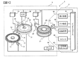
図1は、本開示に係る自動分析装置の一実施例の全体構成図である。 FIG. 1 is an overall configuration diagram of an embodiment of an automatic analyzer according to the present disclosure.
図1において、自動分析装置1は、検体ディスク11と、試薬ディスク21と、反応ディスク31とを有する分析ユニット3を備えている。検体ディスク11には、検体が封入された検体容器10がディスク周方向に沿って複数搭載される。試薬ディスク21は、装置内の試薬保管庫として、試薬が封入された試薬容器20がディスク周方向に沿って複数搭載される。反応ディスク31には、試料(検体)と試薬を反応させて生成した反応液を生成する反応容器30がディスク周方向に沿って複数装着されている。各検体容器10、各試薬容器20は、検体ディスク11、試薬ディスク21に着脱可能に搭載されている。
In FIG. 1, the automatic analyzer 1 includes an
検体ディスク11と反応ディスク31との間、及び試薬ディスク21と反応ディスク31との間には、検体分注機構12、試薬分注機構22が設置されている。検体分注機構12、試薬分注機構22は、可動アームと、可動アームに取り付けられたピペットノズルからなる分注ノズルとを備えている。
A
検体ディスク11、試薬ディスク21は、それぞれ図示せぬ駆動部によって、回動可能に構成されている。検体ディスク11は、その回動によって、搭載されている複数の検体容器10の中の一の検体容器10を、ディスクの周方向に沿った所定位置に配置することができる。同様に、試薬ディスク21も、その回動によって、搭載されている複数の試薬容器20の中の一の試薬容器20を、ディスクの周方向に沿った所定位置に配置することができる。
The
検体ディスク11、試薬ディスク21の周方向に沿った所定位置には、検体情報読取装置13、試薬情報読取装置23が配設されている。検体情報読取装置13、試薬情報読取装置23は、対向する読取位置に配置された検体容器10、試薬容器20に付された記録媒体に固定されている検体コード、試薬コードを読み取る。検体情報読取装置13、試薬情報読取装置23は、検体容器10、試薬容器20の検体コード、試薬コードを読み取ることにより、検体ディスク11、試薬ディスク21上における検体、試薬それぞれの搭載状況を検出できる。
A
検体分注機構12及び試薬分注機構22は、反応容器30内に検体、試薬の混合液すなわち反応液を生成する。反応液の生成に当たって、検体分注機構12は、検体ディスク11の回動によって検体吸入位置に配置された検体容器10から、分注ノズル内に所定量の検体を吸入して収容する。そして、検体分注機構12は、この分注ノズル内に収容されている検体を、反応ディスク31の回動によって検体吐出位置に配置された反応容器30内に吐出して、検体の分注を行う。一方、試薬分注機構22は、試薬ディスク21の回動によって試薬吸入位置に配置された試薬容器20から、分注ノズル内に所定量の試薬を吸入して収容する。そして、試薬分注機構22は、この分注ノズル内に収容されている試薬を、反応ディスク31の回動によって試薬吐出位置に配置された反応容器30内に吐出して、試薬の分注を行う。
The
反応ディスク31のディスク周りには、検体分注機構12、試薬分注機構22とともに、作業位置を互いにずらして、撹拌機構36、測光系37、洗浄機構38が配置されている。撹拌機構36は、検体分注機構12、試薬分注機構22により反応容器30内に分注されて生成された反応液の攪拌を行う。これにより、反応容器30内の反応液は、均一に攪拌されて反応が促進される。
Around the
測光系37は、反応ディスク31の回動に連動して反応容器30が通過する測光位置を挟んで、光源(図示省略)と散乱光度計(図示省略)とが相対向して配置されて構成されている。測光系37は、反応液が収容され、光源と散乱光度計との間の測光位置に位置する反応容器30に、光源から測定光を照射し、その散乱光を散乱光度計により測光する。これにより、各反応容器30内の反応液は、反応ディスク31の間歇回転による回動変位によって、各反応容器30は、測光系37の測光位置に位置される毎に反応液の散乱光が測定される。測光系37は、散乱光度計と同軸光軸上に又は別ポジションに、多波長吸光光度計を備えた構成であってもよい。
The
洗浄機構38は、反応ディスク31に装着された反応容器30について、依頼項目の分析が終わった反応液を廃棄し、新たな依頼項目の分析での使用に備えて容器内の洗浄を行う。洗浄機構38により、反応ディスク31の装着された複数の反応容器30それぞれは、分析での繰り返し使用が可能になる。
The
次に、この自動分析装置1における制御系及び信号処理系について説明する。 Next, a control system and a signal processing system in the automatic analyzer 1 will be described.
自動分析装置1の制御系及び信号処理系は、マイクロコンピュータ(コンピュータ)40を有して構成されている。マイクロコンピュータ40には、インターフェース41を介して、記憶装置42、外部機器インターフェース43、入力装置44、表示装置45、プリンタ46が、それぞれ接続されている。記憶装置42は、ハードディスクメモリや外部記憶メディアにより構成され、作業データ、測定結果データ、分析結果データ等が記憶される。外部機器インターフェース43は、図示せぬ管理装置(上位コンピュータ)との間で、検体情報、分析依頼項目、測定結果、分析結果等の情報伝送を行う。入力装置44は、マウス、キーボード等の操作部を有して構成され、装置に対して各種の指示操作、設定操作を行う。表示装置45は、各種の指示操作や設定操作で使用されるGUI(Graphical User Interface)や、測定結果、分析結果等を表示する。プリンタ46は、測定結果、分析結果等を印字出力する。入力装置44及び表示装置45は、自動分析装置1のユーザーインターフェースを構成する。
The control system and signal processing system of the automatic analyzer 1 are configured to include a microcomputer (computer) 40. A
また、マイクロコンピュータ40には、インターフェース41を介して、検体ディスク11、試薬ディスク21、反応ディスク31、検体情報読取装置13、試薬情報読取装置23、検体分注制御部15、試薬分注制御部25、A/D変換器39といった、装置各部が接続されている。検体分注制御部15、試薬分注制御部25は、マイクロコンピュータ40からの指令を基に、検体分注機構12、試薬分注機構22の作動制御を行い、検体、試薬それぞれの分注動作を制御する。A/D変換器39は、測光系37の散乱光度計のアナログ検出信号をデジタル信号に変換して、マイクロコンピュータ40に供給する。
In addition, the
その上で、自動分析装置1による検体の分析は、上述した制御系及び信号処理系によって、次のように装置各部を作動制御して行われる。 In addition, the analysis of the specimen by the automatic analyzer 1 is performed by controlling the operation of each part of the apparatus as follows by the control system and the signal processing system described above.
記憶装置42には、予め設定された、各オペレータのパスワード、キャリブレーション結果、分析可能な分析依頼項目それぞれの分析パラメータ、各画面の表示レベル等が記憶されている。また、記憶装置42には、検体の分析動作(オペレーション)の開始に先立って、これから分析を行う検体それぞれの検体情報及び分析依頼項目が、例えば外部機器インターフェース43を介して管理装置から伝送され、或いはユーザーインターフェースからオペレータ入力されて登録されている。また、記憶装置42には、検体ディスク11、試薬ディスク21にそれぞれ搭載された検体情報、試薬情報も、検体情報読取装置13、試薬情報読取装置23による検体コード、試薬コードの読み取り出力に基づいて、ディスク上の搭載位置と対応付けて登録される。
The
マイクロコンピュータ40は、検体の分析動作が行われていない待機状態(スタンバイ状態)で、ユーザーインターフェースからオペレーション開始指示のオペレータ入力を受けると、検体ディスク11、試薬ディスク21、反応ディスク31、検体分注機構12、試薬分注機構22等の装置各部を作動制御して、記憶装置42に登録されている検体情報及び依頼項目情報について、分析作業を実行開始する。
When the
分析作業が実行開始されると、検体ディスク11、試薬ディスク21の回動に応じた検体情報読取装置13、試薬情報読取装置23それぞれの読み取り出力に基づいて、検体ディスク11、試薬ディスク21上における検体、試薬の搭載状況が、マイクロコンピュータ40によって取得され、記憶装置42に登録される。
When the analysis work is started, on the
具体的には、検体ディスク11のオペレーション開始時の回動に伴って、検体情報読取装置13により順次読み取られる検体容器10それぞれの検体コードに基づいて、検体ディスク11の周方向に沿って複数搭載された検体容器10それぞれの、検体ディスク11上における搭載ポジションが規定される。これに伴い、検体ディスク11上に搭載された検体容器10それぞれに封入されている検体の検体情報が、検体ディスク11上の搭載ポジションと対応付けされて、記憶装置42に登録される。
Specifically, a plurality of samples are mounted along the circumferential direction of the
同様に、試薬ディスク21のオペレーション開始時の回動に伴って、試薬情報読取装置23により順次読み取られる試薬容器20それぞれの試薬コードに基づいて、試薬ディスク21の周方向に沿って複数搭載された試薬容器20それぞれの、試薬ディスク21上における搭載ポジション等が規定される。これに伴い、試薬ディスク21上に搭載された試薬容器20それぞれに封入されている試薬の試薬情報が、試薬ディスク21上の搭載ポジションと対応付けされて、記憶装置42に登録される。
Similarly, with the rotation of the
これにより、マイクロコンピュータ40は、検体情報読取装置13、試薬情報読取装置23それぞれの読み取り出力に基づいて検体ディスク11、試薬ディスク21の回動変位を制御して、所望の検体及び検体容器10、所望の試薬及び試薬容器20を、検体分注機構12による検体吸入位置、試薬分注機構22による試薬吸入位置に配置することが可能になる。
Thereby, the
このようにして、検体ディスク11、試薬ディスク21上における各検体容器10、各試薬容器20の搭載状況を取得した後、マイクロコンピュータ40は、検体ディスク11の回動により、記憶装置42に登録された依頼項目の分析の中に、未だ分析が済んでいない検体を封入した検体容器10があると、検体分注機構12の検体吸入位置に配置して、反応液の生成を開始する。
In this way, after acquiring the mounting status of each
反応液の生成では、マイクロコンピュータ40は、検体分注機構12に、依頼項目の分析パラメータにしたがって所定量の検体を吸入させ、ノズル内に収容する。その際には、この検体容器10内の検体液量を、この吸入された所定量分だけ減算し、検体容器10内に封入されている検体液量の更新を行う。
In the generation of the reaction solution, the
それから、マイクロコンピュータ40は、反応ディスク31の間歇回動により、検体分注機構12の検体吐出位置に洗浄済の反応容器30が配置されると、検体分注機構12に、ノズル内に収容している所定量の検体をこの反応容器30内に吐出させて検体の分注を行う。そして、この反応容器30とこの検体の依頼項目の分析とを対応づける。例えば、マイクロコンピュータ40は、記憶装置42に登録されているこの検体の依頼項目の分析に対応させて、この反応容器30若しくは反応ディスク31上の装着ポジションを記憶するともに、検体が分注済であることとして検体の分注完了時刻を記憶する。
Then, when the washed
その一方で、マイクロコンピュータ40は、反応ディスク31の間歇回動により、試薬分注タイミングになった依頼項目の分析に対応する反応容器30が試薬分注機構22の試薬吐出位置に配置されるのにタイミングに合わせて、試薬ディスク11を回動変位させて分注する試薬の試薬容器20を試薬分注機構22の試薬吸入位置に配置する。そして、マイクロコンピュータ40は、試薬分注機構22に、この試薬容器20から依頼項目の分析パラメータにしたがって所定量の試薬を吸入させ、ノズル内に収容する。その際には、この試薬容器20内の試薬液量を、この吸入された所定量分だけ減算し、試薬容器20に収容されている試薬液量の更新を行うとともに、試薬ディスク11の試薬種類毎の試薬液量の中、試薬種類が同じ試薬液量についてこの吸入された所定量分だけ減算し、試薬ディスク11の試薬種類毎の試薬液量(試薬残量)の更新を行う。なお、試薬ディスク21上における試薬容器20それぞれの試薬液量は、試薬ディスク21の周方向に沿った所定位置に液量測定機構を設け、直接測定することも可能である。
On the other hand, in the
それから、マイクロコンピュータ40は、反応ディスク31の間歇回動により、この試薬分注タイミングになった検体の依頼項目の分析に対応する反応容器30が試薬分注機構22の試薬吐出位置に配置されると、試薬分注機構22に、ノズル内に収容してある所定量の試薬を反応容器30内に吐出させて、試薬の分注を行う。そして、記憶装置42に登録されているこの検体の依頼項目の分析に対応させて、試薬が分注済であることとして試薬の分注完了時刻を記憶する。
Then, by intermittently rotating the
その一方で、マイクロコンピュータ40は、検体、試薬が分注されて反応液が生成され、分析依頼項目が特定された反応ディスク31上の反応容器30に対しては、検体の依頼項目の分析を行う。
On the other hand, the
この場合、反応容器30に生成された反応液が分析依頼項目の分析パラメータで設定された分析タイミングになると、マイクロコンピュータ40は、反応ディスク31の間歇回動により、その反応容器30を測光系37の測光位置に配置する。反応容器30が測光系37の測光位置に配置されると、マイクロコンピュータ40は、A/D変換器39を介して、その散乱光度計のデジタル検出出力を取り込み、検体の分析依頼項目の測定・分析結果を演算する。そして、記憶装置42に登録されているこの検体の分析依頼項目に対応させて、その測定・分析結果を記憶する。
In this case, when the reaction liquid generated in the
このようにして、自動分析装置1では、オペレーション開始指示のオペレータ入力によりオペレーションが開始され、検体それぞれの依頼項目の分析が開始されると、記憶装置42に登録されている検体それぞれの依頼項目の分析毎に、その検体の分注が済んだか否かを示す検体分注完了時刻情報や、試薬それぞれについての分注が済んだか否か示す試薬分注完了時刻情報や、測定・分析結果等が、オペレーションの進捗に伴って、逐次、追加記憶されて蓄積されていくことになる。
In this manner, in the automatic analyzer 1, when an operation is started by an operator input of an operation start instruction and analysis of each requested item of the sample is started, the request items of each sample registered in the
また、試薬容器20内に封入されて試薬ディスク21に搭載されて保管されている試薬に関しても、試薬容器20それぞれの試薬液量(試薬残量)や、試薬種類毎の試薬液量(試薬残量)が、オペレーションの進捗に伴って、逐次、更新記憶されていくことになる。
In addition, with respect to the reagent sealed in the
その上で、本実施例の自動分析装置1では、正規品に固有の試薬情報の漏洩を防いで、高精度な分析結果の取得を保証するための試薬登録システム2が備えられている。本実施例の自動分析装置1においては、試薬登録システム2は、試薬容器20に付された記録媒体に固定されている試薬コードを読み取る試薬情報読取装置23を用いて構成されている。
In addition, the automatic analyzer 1 of the present embodiment is provided with a
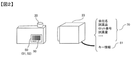
図2は、図1に示した自動分析装置における、試薬ディスクに設置される試薬容器と、試薬情報読取装置との関係を表した図である。 FIG. 2 is a diagram showing the relationship between the reagent container installed on the reagent disk and the reagent information reading device in the automatic analyzer shown in FIG.
分析で使用する試薬は、図2に示すように、試薬容器20に封入された状態で、分析装置メーカー及び/又は正規品試薬メーカーから自動分析装置1のユーザーに、試薬容器20ごと提供される。試薬容器20には、試薬容器20に封入されている試薬の試薬情報70を得るための試薬コード(試薬識別情報)90が固定された識別片50が、試薬容器20に一体不可分に設けられている。識別片50としては、例えば、試薬コード(試薬識別情報)90を埋め込んだタグ(例えば、RFID:radio frequency identifier)51、試薬コード90がQRコードやバーコードで印刷された印刷片52等が使用されている。一方、試薬情報読取装置23としては、識別片50の形式に合わせたリーダが利用される。試薬情報70と試薬コード90との関係は、図3に示すようになっている。
As shown in FIG. 2, the reagent used in the analysis is provided to the user of the automatic analyzer 1 from the analyzer maker and / or the genuine reagent maker together with the
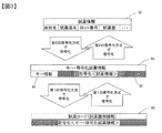
図3は、試薬情報と試薬コードとの関係を表した図である。 FIG. 3 is a diagram showing the relationship between reagent information and reagent codes.
図3において、試薬情報70は、試薬提供メーカーの会社名、試薬品名、ロット番号、試薬量等の当該試薬に関わる固有情報を含んで構成されている。試薬コード90は、キー情報81と、このキー情報81に紐付けされた第2の復号化方式に対応する第2の符号化方式で試薬情報70を符号化(暗号化)してなる符号化試薬情報82とを一体化し、この一体化されたキー情報・符号化試薬情報80全体を第1の符号化方式で符号化されて構成されている。したがって、試薬コード90では、試薬情報70は、第2の復号化方式で符号化され、さらに第1の符号化方式で符号化された状態になっている。そのため、第1の符号化方式及び/又は第1の復号化方式が解析されてしまっても、正規品の試薬の試薬情報70が露見してしまうことはない。
In FIG. 3, the
本実施例の自動分析装置1における試薬登録システム2では、反応液を生成するために、試薬ディスク21上に搭載された試薬容器20それぞれについて、試薬容器20に封入されている試薬の試薬情報70を試薬ディスク21上の搭載ポジションと対応付けて記憶装置42に登録する。そのために、試薬登録システム2は、試薬情報読取装置23に加えて、第1の復号化部及び第2の復号化部を、上述した試薬情報70と試薬コード90との関係から有している。
In the
第1の復号化部には、試薬情報読取装置23が読み取った試薬コード90が入力される。また、第2の復号化部には、第1の復号化部で復号化されたキー情報・符号化試薬情報80が入力される。第2の復号化部は、第1の復号化部で復号化されたキー情報81に紐付けされた第2の復号化方式で、符号化試薬情報82を復号化して試薬情報70を出力する。そのため、第2の復号化部には、復号キーリストが付設され、キー情報81それぞれと第2の復号化方式それぞれとの対応関係が記録されている。そして、第2の復号化部で取得された試薬情報70は、反応液を生成するために、試薬ディスク21上の搭載ポジションと対応付けて記憶装置42に登録される。
The
図1に示した自動分析装置1においては、試薬登録システム2は、試薬情報読取装置23とインターフェース41を介して接続されたマイクロコンピュータ40及び記憶装置42によって実現される。記憶装置42には、復号キーリスト、及び各キー情報81に対応した第2の復号化方式それぞれが記憶されている。
In the automatic analyzer 1 shown in FIG. 1, the
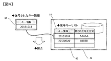
図4は、復号キーリストの模式図である。 FIG. 4 is a schematic diagram of a decryption key list.
図4に示すように、復号キーリスト60は、キー情報81それぞれに対応した第2の復号化方式が記録されている。図示の例では、試薬コード90が第1の復号化方式で復号化されてキー情報・符号化試薬情報80のキー情報81として‘20151014’が取得されると、キー情報・符号化試薬情報80の符号化試薬情報82を復号化する第2の符号化方式として、‘AAAAA’が照合・選択されることを示している。
As shown in FIG. 4, the decryption
復号キーリスト60では、定期的(例えば、月単位)に、キー情報81と第2の符号化方式との対応関係を変更し、併せて、第1の復号化方式を追加することで、セキュリティを高めることができる。また、復号キーリスト60から、使用期限の過ぎた試薬容器20のキー情報81を削除することで、復号キーリスト60の肥大を防ぐことができる。また、復号キーリスト60のリスト内容は、インターフェース41を介して、ユーザー変更可能である。また、インターフェース41及び外部機器インターフェース43を介して、分析装置メーカー及び/又は正規品試薬メーカーがオフライン又はオンラインで更新できるようにすることも可能である。
In the decryption
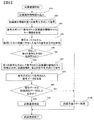
図5は、自動分析装置の試薬登録システムが行う試薬登録処理のフローチャートである。 FIG. 5 is a flowchart of a reagent registration process performed by the reagent registration system of the automatic analyzer.
オペレータのオペレーション開始指示により、自動分析装置1では、まず、検体ディスク11に搭載された検体容器10それぞれに封入されている検体の検体情報や、試薬ディスク21に搭載された試薬容器20それぞれに封入されている試薬の試薬情報の登録が行われる。試薬登録システム2では、試薬情報読取装置23が、試薬ディスク21のオペレーション開始時の回動に伴って読取位置に配置された試薬容器20から、試薬コード(試薬識別情報)90の読み込みを実行する(ステップS10)。
In response to the operation start instruction from the operator, the automatic analyzer 1 first encloses the sample information of the sample enclosed in each of the
試薬情報読取装置23が読み取った試薬容器20の試薬コード90は、試薬登録システム2によって第1の復号化方式で復号化され(S20)、キー情報・符号化試薬情報80が取得される(S30)。この時、符号化されていない情報として取得されるのはキー情報81だけで、試薬情報70は、未だ符号化試薬情報82として符号化(暗号化)されたままである。また、キー情報81は、符号化試薬情報82を復号化して試薬情報70を特定するための任意の文字列である。例えば、この任意の文字列には、試薬の製造年月日等も利用可能である。
The
試薬登録システム2は、第1の復号化方式で復号されたキー情報81と復号キーリスト60とを用いて、符号化試薬情報82を復号化するための第2の復号化方式を取得する(S40)。この場合、試薬登録システム2は、図4に示した復号キーリスト60に対し、同図に示すように、ステップS30で取得されたキー情報・符号化試薬情報80のキー情報81を照会(例えば、2分木探索 )することで、このキー情報81に対応する第2の復号化方式を取得する。
The
しかし、復号キーリスト60からキー情報81に対応する第2の復号化方式を取得することができない場合は(S50)、試薬登録システム2は、試薬登録エラー処理を実施する(S100)。これにより、先にステップS10で試薬コード90の読み込みを行った試薬容器20については、その試薬の登録が中止終了になる。
However, if the second decryption method corresponding to the
このような場合には、ステップS10での読み込みを行った試薬容器20の試薬コード90自体が図3に示したフォーマット構造になっていない場合や、ステップS30で取得したキー情報81やこのキー情報81に対応する第2の復号化方式が復号キーリスト60に存在しない場合が含まれる。そして、このような試薬コード90を有する試薬容器20には、非正規品の試薬が封入された試薬容器20も含まれることになる。
In such a case, the
一方、ステップS50で、復号キーリスト60からキー情報81に対応する第2の復号化方式を取得することができた場合は、試薬登録システム2は、この取得した第2の復号化方式で、キー情報81以外の未復号部分である、符号化試薬情報80の符号化試薬情報82を復号化して(S60)、試薬情報70を取得する(S70)。
On the other hand, if the second decryption method corresponding to the
試薬登録システム2は、復号化されたキー情報81以外の未復号部分である試薬情報70が、正規品として正常であるか否かを確認し(S80)、正規品として正常でない場合には、試薬登録エラー処理(S100)を実施し、手順を終了する。例えば、この正規品として正常でない場合には、試薬容器20の試薬液量(試薬残量)不足等が含まれる。
The
これに対し、正規品として正常である場合は、試薬登録システム2は、試薬情報70の登録を実施し(S90)、手順を終了する。
自動分析装置1は、手順終了後に、この登録した試薬情報を用いて、分析すなわち試薬と検体を混合した反応液の生成を実施できる。
On the other hand, when the product is normal as a regular product, the
After the procedure is completed, the automatic analyzer 1 can perform analysis, that is, generate a reaction liquid in which the reagent and the sample are mixed, using the registered reagent information.
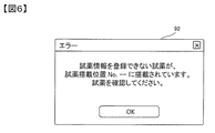
図6は、表示装置に表示される試薬登録不可通知の一例を示した図である。 FIG. 6 is a diagram illustrating an example of a reagent registration failure notification displayed on the display device.
ステップS100の試薬登録エラー処理では、図6で示すようなエラー画面92を表示装置45に表示し、オペレータに対して、試薬ディスク21の該当試薬搭載位置に搭載された試薬が正常でないことを伝えることが可能である。この場合、試薬ディスク21の該当試薬搭載位置が指示されるので、該当の試薬容器20の取り除きも容易である。この場合、エラー画面92には、例えば “復号キーリスト60にキー情報81が登録されていない”、“これから分析作業を開始するに当たって試薬液量(試薬残量)が不足している”等の、試薬が正常でない理由を併せて表示することも可能である。
In the reagent registration error process of step S100, an
自動分析装置が提供する分析の結果は、試薬の品質に依存する部分が大きく、正しく品質管理された試薬が、その使用期限内に用いられることが必要不可欠である。しかし、従来技術の試薬情報登録処理では、試薬容器に付される情報に関して、単一な暗号化及び照合しか成されていない。そのため、その単一な暗号化方式及び照合方式が、悪意ある第三者により認知されてしまった場合には、試薬識別情報の漏洩及び改変(例えば、試薬期限の改変)、非正規品の流通を防ぐことができなかった。 The result of analysis provided by the automatic analyzer largely depends on the quality of the reagent, and it is essential that a reagent whose quality is correctly controlled be used within its expiration date. However, in the conventional reagent information registration process, only single encryption and verification are performed on the information attached to the reagent container. Therefore, if the single encryption method and verification method are recognized by a malicious third party, leakage and modification of reagent identification information (for example, modification of reagent expiration date), distribution of non-genuine products Could not prevent.
これに対し、本実施例の自動分析装置1においては、試薬情報を解読するためには、装置内の記憶装置42に格納されている復号キーリスト60を介さねばならず、試薬情報登録処理に対する悪意ある第三者の介入を抑制することができる。また、悪意ある第三者に、第1の復号化方式が漏洩してしまった場合にも、定期的(例えば、月単位)に第1の復号化方式を変更したり、併せて復号キーリスト60に新たな第2の復号化方式を追加することで、それ以降に作成された試薬情報の復号を不可能にすることができる。この場合、この復号キーリスト60に新たな第2の復号化方式を追加する手法は、新たなキー情報81と第2の復号化方式とをセットで追加する手法に限定されるものではない。例えば、既存のキーリスト60のキー情報81又は第2の復号化方式の中の少なくとも一方を、新たな別のキー情報81又は第2の復号化方式に変更することも含まれる。加えて、このような漏洩が生じた場合でも、未使用又は使用途中の正規試薬品を所持しているユーザーに対しては、その所持する試薬品それぞれに対して新しい試薬コード(試薬識別情報)を配布することによって容易に対処できるので、悪意ある第三者の介入に対して迅速な対応をはかることができる。
On the other hand, in the automatic analyzer 1 of this embodiment, in order to decrypt the reagent information, the decryption
次に、上述した自動分析装置1の記憶装置42に保持される第2の復号化方式の提供モデルについて説明する。なお、提供モデルは、以下のモデルに限定されるものでなく、種々の提供の仕方が可能である。
Next, the provision model of the second decoding method held in the
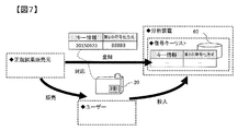
図7は、自動分析装置に対する第2の復号化方式の提供モデルに係る第1の実施例の説明図である。 FIG. 7 is an explanatory diagram of the first embodiment relating to a second decoding method providing model for the automatic analyzer.
前述した実施例では、記憶装置42に登録する復号キーリスト60について制限をかけてはいなかったが、図7で示すように、正規品試薬メーカーによって、正規品試薬の販売時に、販売試薬が封入された試薬容器20と対応する第2の符号化方式のみを、ユーザー所有の自動分析装置1の復号キーリスト60へ登録する方式にすることもできる。これにより、ユーザー所有の復号キーリスト60は、正規品試薬メーカーによって提供された試薬第2の符号化方式しか持たず、試薬情報を不正にコピーされた非正規試薬が装置に登録されるおそれを低減することができる。
In the above-described embodiment, the decryption
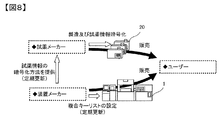
図8は、自動分析装置に対する第2の復号化方式の提供モデルに係る第2の実施例の説明図である。 FIG. 8 is an explanatory diagram of a second embodiment according to the second decoding method providing model for the automatic analyzer.
本実施例では、試薬情報の符号化及び復号キーリストをネットワーク経由で更新する。分析装置メーカーは、正規品試薬メーカーに対し試薬容器20に付与される試薬情報の符号化方法(暗号化方法)を提供する。符号化方式は、定期的に更新され、分析装置メーカーが製造した装置で正規品試薬メーカーが製造した試薬を使用する限り、定期的に分析装置メーカーから正規品試薬メーカーに対して提供される。
In this embodiment, the reagent information encoding and decoding key lists are updated via the network. The analyzer manufacturer provides a method for encoding reagent information (encryption method) to the
ユーザーは、分析装置メーカーから自動分析装置1を購入し、試薬メーカーから試薬を試薬容器20ごと購入する。購入した試薬が自動分析装置1の復号キーリスト60で復号化可能であれば、試薬が、分析装置メーカーが想定した正規の正規品試薬メーカーのものであると判断できる。
The user purchases the automatic analyzer 1 from the analyzer manufacturer, and purchases the reagent together with the
試薬情報の符号化方法を悪意ある第三者に解読された場合においても、復号キーリスト60と符号化方法を定期的に更新することでリスクを低減することができる。加えて、正規品試薬メーカーがユーザーに対し販売した試薬に対応する復号キーリスト60のみを更新することで、このリスクは更に低減可能である。
Even when the encoding method of the reagent information is decoded by a malicious third party, the risk can be reduced by periodically updating the decoding
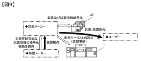
図9は、自動分析装置に対する第2の復号化方式の提供モデルに係る第3の実施例の説明図である。 FIG. 9 is an explanatory diagram of a third embodiment according to the second decoding method provision model for the automatic analyzer.
本実施例も、試薬情報の符号化及び復号キーリストをネットワーク経由で更新する。正規品試薬メーカーが、ユーザーに対し試薬と自動分析装置1を合わせて提供する場合のビジネスモデルである。この場合、分析装置メーカーは、正規品試薬メーカーに対し、定期的に更新可能な試薬情報の暗号化機能を提供することとなる。これにより、正規品試薬メーカーは、ユーザーが非正規試薬を使用してしまうリスクを低減することができる。 Also in this embodiment, the reagent information encoding and decoding key list is updated via the network. This is a business model when a genuine reagent maker provides a reagent and an automatic analyzer 1 to a user. In this case, the analyzer manufacturer will provide a reagent information encryption function that can be updated periodically to the genuine reagent manufacturer. Thereby, the genuine reagent maker can reduce a risk that a user will use a non-regular reagent.
図10は、自動分析装置に対する第2の復号化方式の提供モデルに係る第4の実施例の説明図である。 FIG. 10 is an explanatory diagram of a fourth embodiment according to the second decoding method provision model for the automatic analyzer.
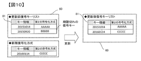
本実施例では、試薬情報の第1及び/又は第2の符号化方式及び復号キーリスト60を更新する。自動分析装置1の記憶装置42に保存された第1及び/又は第2の符号化方式及び復号キーリスト60を更新するための手段として、自動分析装置1に繋がった施設内ネットワークの利用や、記憶媒体(USB等)の利用等、複数の方法が想定される。どの方式を使用するとしても、復号キーリスト60が外部に漏洩することなく、また、自動分析装置1に漏れなく保存されることが重要である。
In this embodiment, the reagent information first and / or second encoding method and the decryption
復号キーリスト60の更新の際には、新たに使用する新規なキー情報81や第2の復号化方式を追加するだけでなく、期限切れのキー情報81や第2の復号化方式を削除することで、復号キーリスト60の肥大化を防ぐだけでなく、期限切れの第2の暗号方式で暗号化された試薬情報をデッドコピーした非正規試薬の登録を防止することができる。第2の復号化方式の期限切れとは、例えば、所定の第2の復号化方式に対応する第2の符号化方式で符号化された試薬情報を有する試薬の有効期限が切れている場合を指す。
When updating the decryption
1 自動分析装置、 2 試薬登録システム、 3 分析ユニット、
10 検体容器、 11 検体ディスク、 12 検体分注機構、
13 検体情報読取装置、 20 試薬容器、 21 試薬ディスク、
22 試薬分注機構、 23 試薬情報読取装置、 30 反応容器、
31 反応ディスク、 36 撹拌機構、 37 測光系、
38 洗浄機構、 40 マイクロコンピュータ(コンピュータ)、
41 インターフェース、 42 記憶装置、 43 外部機器インターフェース、
44 入力装置、 45 表示装置、 46 プリンタ、 50 識別片、
51 タグ、 52 印刷片、 60 復号キーリスト、 70 試薬情報、
80 キー情報・符号化試薬情報、 81 キー情報、 82 符号化試薬情報、
90 試薬コード(試薬識別情報)、 92 エラー画面。
1 automatic analyzer, 2 reagent registration system, 3 analysis unit,
10 specimen containers, 11 specimen discs, 12 specimen dispensing mechanisms,
13 specimen information reading device, 20 reagent container, 21 reagent disk,
22 reagent dispensing mechanism, 23 reagent information reader, 30 reaction vessel,
31 reaction disk, 36 stirring mechanism, 37 photometric system,
38 Cleaning mechanism, 40 Microcomputer (computer),
41 interface, 42 storage device, 43 external device interface,
44 input devices, 45 display devices, 46 printers, 50 identification pieces,
51 tag, 52 printed piece, 60 decryption key list, 70 reagent information,
80 key information / encoded reagent information, 81 key information, 82 encoded reagent information,
90 Reagent code (reagent identification information), 92 Error screen.
Claims (7)
反応液の生成に使用する試薬の試薬情報を登録する試薬登録部を備え、
前記試薬登録部は、
試薬が封入された試薬容器に固定され、第1の符号化方式で符号化された試薬識別情報を復号化し、第2の符号化方式で符号化された試薬情報と当該第2の符号化方式を特定するキー情報を取得する第1の復号化部と、
前記第1の復号化部により復号化された、第2の符号化方式で符号化された試薬情報を、同じく復号化されたキー情報に対応する第2の復号化方式で復号化して、試薬情報を復号化する第2の復号化部と
を有する自動分析装置。 An automatic analyzer for analyzing a reaction solution generated by mixing a reagent and a sample,
A reagent registration unit is provided for registering reagent information of reagents used for generating reaction solutions.
The reagent registration unit
Reagent information that is fixed to the reagent container in which the reagent is sealed and encoded by the first encoding method is decoded, and the reagent information encoded by the second encoding method and the second encoding method A first decryption unit for obtaining key information for identifying
Reagent information decoded by the first decoding unit and encoded by the second encoding method is decoded by a second decoding method corresponding to the decoded key information, and a reagent is obtained. An automatic analyzer having a second decryption unit for decrypting information.
前記第2の復号化部は、前記第1の復号化部により復号化されたキー情報に対応する第2の復号化方式を、前記復号キーリストの複数の第2の復号化方式の中から取得する、
請求項1に記載の自動分析装置。 The second decryption unit is provided with a decryption key list in which the correspondence between each key information and each second decryption method is stored,
The second decryption unit selects a second decryption method corresponding to the key information decrypted by the first decryption unit from a plurality of second decryption methods in the decryption key list. get,
The automatic analyzer according to claim 1.
請求項1に記載の自動分析装置。 The correspondence relationship between each key information stored in the decryption key list and each second decryption method is updated offline or online.
The automatic analyzer according to claim 1.
請求項1に記載の自動分析装置。 The reagent identification information encoded by the first encoding method is readable and fixed to an identification piece that is inseparably provided in the reagent container.
The automatic analyzer according to claim 1.
請求項1に記載の自動分析装置。 When the second decryption unit cannot obtain the second decryption method corresponding to the key information decrypted by the first decryption unit, an alarm is output.
The automatic analyzer according to claim 1.
反応液の生成に使用する試薬の試薬情報を登録する際、
試薬が封入された試薬容器に固定され、第1の符号化方式で符号化された試薬識別情報を復号化し、第2の符号化方式で符号化された試薬情報と当該第2の符号化方式を特定するキー情報を取得する第1の復号化ステップと、
前記第1の復号化ステップにより復号化された、第2の符号化方式で符号化された試薬情報を、同じく復号化されたキー情報に対応する第2の復号化方式で復号化して、試薬情報を復号化する第2の復号化ステップと
を有する自動分析方法。 An automatic analysis method for analyzing a reaction solution generated by mixing a reagent and a sample,
When registering reagent information for reagents used to generate reaction solutions,
Reagent information that is fixed to the reagent container in which the reagent is sealed and encoded by the first encoding method is decoded, and the reagent information encoded by the second encoding method and the second encoding method A first decryption step for obtaining key information for identifying
Reagent information decoded by the second encoding method, decoded by the first decoding step, is decoded by a second decoding method corresponding to the decoded key information. And a second decryption step for decrypting the information.
試薬が封入された試薬容器に固定された試薬識別情報を読み取る試薬情報装置と、
前記試薬情報装置により読み取った試薬識別情報を第1の符号化方式で復号化し、第2の符号化方式で符号化された試薬情報と当該第2の符号化方式を特定するキー情報を取得する第1の復号化部と、
前記第1の復号化部により復号化された、第2の符号化方式で符号化された試薬情報を、同じく復号化されたキー情報に対応する第2の復号化方式で復号化して、試薬情報を復号化する第2の復号化部と
を有する試薬登録システム。 A reagent registration system for registering reagent information of a reagent used for generating a reaction solution,
A reagent information device for reading reagent identification information fixed to a reagent container in which a reagent is sealed; and
Reagent identification information read by the reagent information device is decoded by the first encoding method, and reagent information encoded by the second encoding method and key information for specifying the second encoding method are acquired. A first decryption unit;
Reagent information decoded by the first decoding unit and encoded by the second encoding method is decoded by a second decoding method corresponding to the decoded key information, and a reagent is obtained. The reagent registration system which has a 2nd decoding part which decodes information.
Priority Applications (1)
| Application Number | Priority Date | Filing Date | Title |
|---|---|---|---|
| JP2016137802A JP6691845B2 (en) | 2016-07-12 | 2016-07-12 | Automatic analyzer, automatic analysis method, and reagent registration system |
Applications Claiming Priority (1)
| Application Number | Priority Date | Filing Date | Title |
|---|---|---|---|
| JP2016137802A JP6691845B2 (en) | 2016-07-12 | 2016-07-12 | Automatic analyzer, automatic analysis method, and reagent registration system |
Publications (2)
| Publication Number | Publication Date |
|---|---|
| JP2018009841A true JP2018009841A (en) | 2018-01-18 |
| JP6691845B2 JP6691845B2 (en) | 2020-05-13 |
Family
ID=60995324
Family Applications (1)
| Application Number | Title | Priority Date | Filing Date |
|---|---|---|---|
| JP2016137802A Active JP6691845B2 (en) | 2016-07-12 | 2016-07-12 | Automatic analyzer, automatic analysis method, and reagent registration system |
Country Status (1)
| Country | Link |
|---|---|
| JP (1) | JP6691845B2 (en) |
Cited By (2)
| Publication number | Priority date | Publication date | Assignee | Title |
|---|---|---|---|---|
| JPWO2021065650A1 (en) * | 2019-09-30 | 2021-04-08 | ||
| US20210318347A1 (en) * | 2020-04-14 | 2021-10-14 | Jeol Ltd. | Automatic Analyzer and Control Method for Automatic Analyzer |
Citations (6)
| Publication number | Priority date | Publication date | Assignee | Title |
|---|---|---|---|---|
| JP2003535348A (en) * | 2000-06-06 | 2003-11-25 | グラクソ グループ リミテッド | Sample container with radio frequency identification tag |
| JP2007124502A (en) * | 2005-10-31 | 2007-05-17 | Canon Inc | Image processing system, image processing method, program and storage medium |
| JP2008311806A (en) * | 2007-06-13 | 2008-12-25 | Isp:Kk | Content providing system |
| JP2009069100A (en) * | 2007-09-18 | 2009-04-02 | Sysmex Corp | Specimen analyzer |
| JP2010060431A (en) * | 2008-09-03 | 2010-03-18 | Toshiba Corp | Automatic analyzer |
| US20130198529A1 (en) * | 2010-10-18 | 2013-08-01 | Fraunhofer-Gesellschaft Zur Foerderung Der Angewandten Forschung E.V. | Sample carrier unit having sample data encryption and method for use thereof |
-
2016
- 2016-07-12 JP JP2016137802A patent/JP6691845B2/en active Active
Patent Citations (6)
| Publication number | Priority date | Publication date | Assignee | Title |
|---|---|---|---|---|
| JP2003535348A (en) * | 2000-06-06 | 2003-11-25 | グラクソ グループ リミテッド | Sample container with radio frequency identification tag |
| JP2007124502A (en) * | 2005-10-31 | 2007-05-17 | Canon Inc | Image processing system, image processing method, program and storage medium |
| JP2008311806A (en) * | 2007-06-13 | 2008-12-25 | Isp:Kk | Content providing system |
| JP2009069100A (en) * | 2007-09-18 | 2009-04-02 | Sysmex Corp | Specimen analyzer |
| JP2010060431A (en) * | 2008-09-03 | 2010-03-18 | Toshiba Corp | Automatic analyzer |
| US20130198529A1 (en) * | 2010-10-18 | 2013-08-01 | Fraunhofer-Gesellschaft Zur Foerderung Der Angewandten Forschung E.V. | Sample carrier unit having sample data encryption and method for use thereof |
Cited By (6)
| Publication number | Priority date | Publication date | Assignee | Title |
|---|---|---|---|---|
| JPWO2021065650A1 (en) * | 2019-09-30 | 2021-04-08 | ||
| WO2021065650A1 (en) | 2019-09-30 | 2021-04-08 | 積水メディカル株式会社 | Genuine product automatic authentiation method |
| JP7153807B2 (en) | 2019-09-30 | 2022-10-14 | 積水メディカル株式会社 | Genuine product automatic authentication method |
| US20210318347A1 (en) * | 2020-04-14 | 2021-10-14 | Jeol Ltd. | Automatic Analyzer and Control Method for Automatic Analyzer |
| JP2021169939A (en) * | 2020-04-14 | 2021-10-28 | 日本電子株式会社 | Automatic analyzer and automatic analyzer control method |
| JP7073438B2 (en) | 2020-04-14 | 2022-05-23 | 日本電子株式会社 | Automatic analyzer and control method of automated analyzer |
Also Published As
| Publication number | Publication date |
|---|---|
| JP6691845B2 (en) | 2020-05-13 |
Similar Documents
| Publication | Publication Date | Title |
|---|---|---|
| JP5123111B2 (en) | Automatic analyzer | |
| EP1873530B1 (en) | Sample analyzer | |
| US10101348B2 (en) | Sample analyzer | |
| JP5277245B2 (en) | Automatic analyzer | |
| US5719059A (en) | Reagent management method and apparatus therefor | |
| US20100001854A1 (en) | Analyzer and analysis method | |
| RU2442164C2 (en) | System for measuring the concentration of the analyze in a sample of body fluid | |
| JP6691845B2 (en) | Automatic analyzer, automatic analysis method, and reagent registration system | |
| JP2005043137A (en) | Auto | |
| JP2013134140A (en) | Automatic analyzer and specimen dispensation method in the same | |
| WO2023002762A1 (en) | Automatic analysis device and sample information display method | |
| US11067587B2 (en) | Automatic analysis device | |
| US20110026705A1 (en) | Method and system for preventing copy of platform | |
| EP3709024B1 (en) | Apparatus for analyzing biological samples | |
| JP2004271327A (en) | Analysis apparatus and audit trail management system | |
| JP6742963B2 (en) | Automatic analyzer and image processing method | |
| JP6147557B2 (en) | Automatic analyzer | |
| JP2017111146A (en) | Method for restoring settings of instrument for processing sample or reagent, and system comprising instrument for processing sample or reagent | |
| JP4185845B2 (en) | Automatic analyzer | |
| JP2009244238A (en) | Automatic analyzer | |
| JP6925194B2 (en) | Automatic analyzer | |
| JP7073438B2 (en) | Automatic analyzer and control method of automated analyzer | |
| US20220222685A1 (en) | Genuine product automatic authentication method | |
| WO2023007936A1 (en) | Automatic analysis device and reagent management method | |
| JP2006046930A (en) | Gas detector |
Legal Events
| Date | Code | Title | Description |
|---|---|---|---|
| A621 | Written request for application examination |
Free format text: JAPANESE INTERMEDIATE CODE: A621 Effective date: 20190424 |
|
| TRDD | Decision of grant or rejection written | ||
| A977 | Report on retrieval |
Free format text: JAPANESE INTERMEDIATE CODE: A971007 Effective date: 20200325 |
|
| A01 | Written decision to grant a patent or to grant a registration (utility model) |
Free format text: JAPANESE INTERMEDIATE CODE: A01 Effective date: 20200331 |
|
| A61 | First payment of annual fees (during grant procedure) |
Free format text: JAPANESE INTERMEDIATE CODE: A61 Effective date: 20200413 |
|
| R150 | Certificate of patent or registration of utility model |
Ref document number: 6691845 Country of ref document: JP Free format text: JAPANESE INTERMEDIATE CODE: R150 |