JP2017529566A - Optical fiber technology that can be transferred between duplex multi-core technology and parallel multi-core technology - Google Patents
Optical fiber technology that can be transferred between duplex multi-core technology and parallel multi-core technology Download PDFInfo
- Publication number
- JP2017529566A JP2017529566A JP2017511838A JP2017511838A JP2017529566A JP 2017529566 A JP2017529566 A JP 2017529566A JP 2017511838 A JP2017511838 A JP 2017511838A JP 2017511838 A JP2017511838 A JP 2017511838A JP 2017529566 A JP2017529566 A JP 2017529566A
- Authority
- JP
- Japan
- Prior art keywords
- tray
- base
- fiber optic
- module
- optical fiber
- Prior art date
- Legal status (The legal status is an assumption and is not a legal conclusion. Google has not performed a legal analysis and makes no representation as to the accuracy of the status listed.)
- Pending
Links
Images


Classifications
-
- G—PHYSICS
- G02—OPTICS
- G02B—OPTICAL ELEMENTS, SYSTEMS OR APPARATUS
- G02B6/00—Light guides; Structural details of arrangements comprising light guides and other optical elements, e.g. couplings
- G02B6/44—Mechanical structures for providing tensile strength and external protection for fibres, e.g. optical transmission cables
- G02B6/4439—Auxiliary devices
- G02B6/444—Systems or boxes with surplus lengths
- G02B6/4453—Cassettes
-
- G—PHYSICS
- G02—OPTICS
- G02B—OPTICAL ELEMENTS, SYSTEMS OR APPARATUS
- G02B6/00—Light guides; Structural details of arrangements comprising light guides and other optical elements, e.g. couplings
- G02B6/24—Coupling light guides
- G02B6/36—Mechanical coupling means
- G02B6/38—Mechanical coupling means having fibre to fibre mating means
- G02B6/3807—Dismountable connectors, i.e. comprising plugs
- G02B6/381—Dismountable connectors, i.e. comprising plugs of the ferrule type, e.g. fibre ends embedded in ferrules, connecting a pair of fibres
- G02B6/3825—Dismountable connectors, i.e. comprising plugs of the ferrule type, e.g. fibre ends embedded in ferrules, connecting a pair of fibres with an intermediate part, e.g. adapter, receptacle, linking two plugs
-
- G—PHYSICS
- G02—OPTICS
- G02B—OPTICAL ELEMENTS, SYSTEMS OR APPARATUS
- G02B6/00—Light guides; Structural details of arrangements comprising light guides and other optical elements, e.g. couplings
- G02B6/24—Coupling light guides
- G02B6/36—Mechanical coupling means
- G02B6/38—Mechanical coupling means having fibre to fibre mating means
- G02B6/3807—Dismountable connectors, i.e. comprising plugs
- G02B6/3873—Connectors using guide surfaces for aligning ferrule ends, e.g. tubes, sleeves, V-grooves, rods, pins, balls
- G02B6/3874—Connectors using guide surfaces for aligning ferrule ends, e.g. tubes, sleeves, V-grooves, rods, pins, balls using tubes, sleeves to align ferrules
- G02B6/3878—Connectors using guide surfaces for aligning ferrule ends, e.g. tubes, sleeves, V-grooves, rods, pins, balls using tubes, sleeves to align ferrules comprising a plurality of ferrules, branching and break-out means
- G02B6/3879—Linking of individual connector plugs to an overconnector, e.g. using clamps, clips, common housings comprising several individual connector plugs
-
- G—PHYSICS
- G02—OPTICS
- G02B—OPTICAL ELEMENTS, SYSTEMS OR APPARATUS
- G02B6/00—Light guides; Structural details of arrangements comprising light guides and other optical elements, e.g. couplings
- G02B6/24—Coupling light guides
- G02B6/36—Mechanical coupling means
- G02B6/38—Mechanical coupling means having fibre to fibre mating means
- G02B6/3807—Dismountable connectors, i.e. comprising plugs
- G02B6/3873—Connectors using guide surfaces for aligning ferrule ends, e.g. tubes, sleeves, V-grooves, rods, pins, balls
- G02B6/3885—Multicore or multichannel optical connectors, i.e. one single ferrule containing more than one fibre, e.g. ribbon type
-
- G—PHYSICS
- G02—OPTICS
- G02B—OPTICAL ELEMENTS, SYSTEMS OR APPARATUS
- G02B6/00—Light guides; Structural details of arrangements comprising light guides and other optical elements, e.g. couplings
- G02B6/24—Coupling light guides
- G02B6/36—Mechanical coupling means
- G02B6/38—Mechanical coupling means having fibre to fibre mating means
- G02B6/3807—Dismountable connectors, i.e. comprising plugs
- G02B6/3897—Connectors fixed to housings, casing, frames or circuit boards
-
- G—PHYSICS
- G02—OPTICS
- G02B—OPTICAL ELEMENTS, SYSTEMS OR APPARATUS
- G02B6/00—Light guides; Structural details of arrangements comprising light guides and other optical elements, e.g. couplings
- G02B6/44—Mechanical structures for providing tensile strength and external protection for fibres, e.g. optical transmission cables
- G02B6/4439—Auxiliary devices
- G02B6/444—Systems or boxes with surplus lengths
- G02B6/4452—Distribution frames
- G02B6/44526—Panels or rackmounts covering a whole width of the frame or rack
-
- G—PHYSICS
- G02—OPTICS
- G02B—OPTICAL ELEMENTS, SYSTEMS OR APPARATUS
- G02B6/00—Light guides; Structural details of arrangements comprising light guides and other optical elements, e.g. couplings
- G02B6/44—Mechanical structures for providing tensile strength and external protection for fibres, e.g. optical transmission cables
- G02B6/4439—Auxiliary devices
- G02B6/444—Systems or boxes with surplus lengths
- G02B6/44528—Patch-cords; Connector arrangements in the system or in the box
-
- G—PHYSICS
- G02—OPTICS
- G02B—OPTICAL ELEMENTS, SYSTEMS OR APPARATUS
- G02B6/00—Light guides; Structural details of arrangements comprising light guides and other optical elements, e.g. couplings
- G02B6/44—Mechanical structures for providing tensile strength and external protection for fibres, e.g. optical transmission cables
- G02B6/4439—Auxiliary devices
- G02B6/4471—Terminating devices ; Cable clamps
-
- G—PHYSICS
- G02—OPTICS
- G02B—OPTICAL ELEMENTS, SYSTEMS OR APPARATUS
- G02B6/00—Light guides; Structural details of arrangements comprising light guides and other optical elements, e.g. couplings
- G02B6/44—Mechanical structures for providing tensile strength and external protection for fibres, e.g. optical transmission cables
- G02B6/4439—Auxiliary devices
- G02B6/444—Systems or boxes with surplus lengths
- G02B6/4453—Cassettes
- G02B6/4455—Cassettes characterised by the way of extraction or insertion of the cassette in the distribution frame, e.g. pivoting, sliding, rotating or gliding
-
- G—PHYSICS
- G02—OPTICS
- G02B—OPTICAL ELEMENTS, SYSTEMS OR APPARATUS
- G02B6/00—Light guides; Structural details of arrangements comprising light guides and other optical elements, e.g. couplings
- G02B6/44—Mechanical structures for providing tensile strength and external protection for fibres, e.g. optical transmission cables
- G02B6/4439—Auxiliary devices
- G02B6/4471—Terminating devices ; Cable clamps
- G02B6/44715—Fan-out devices
Landscapes
- Physics & Mathematics (AREA)
- General Physics & Mathematics (AREA)
- Optics & Photonics (AREA)
- Light Guides In General And Applications Therefor (AREA)
- Mechanical Coupling Of Light Guides (AREA)
- Preliminary Treatment Of Fibers (AREA)
- Optical Couplings Of Light Guides (AREA)
Abstract
デュプレックス伝送方式から8心パラレル(並列)伝送方式への移行・8心パラレル(並列)伝送方式からデュプレックス伝送方式への移行を可能にする8心MPO形態を支持する光ファイバ機器。光ファイバ機器は、光ファイバ機器を取り付けるためのトレーを有する。このトレーは、複数のBASE‐8型光ファイバ機器を支持するベースを有する。トレーは、トレーを光ファイバ機器シャーシ内に可動的に設置するためのベースの1本または2本以上の支持レールを更に有する。トレーは、複数のBASE‐8型光ファイバ機器をトレーに可動的に取り付けるためのベースの複数の機器支持レールを更に有する。An optical fiber device supporting an 8-core MPO configuration that enables a transition from a duplex transmission system to an 8-core parallel (parallel) transmission system and a transition from an 8-core parallel (parallel) transmission system to a duplex transmission system. The fiber optic equipment has a tray for mounting the fiber optic equipment. The tray has a base that supports a plurality of BASE-8 type fiber optic equipment. The tray further includes one or more support rails of the base for movably installing the tray within the fiber optic equipment chassis. The tray further includes a plurality of base equipment support rails for movably attaching a plurality of BASE-8 type fiber optic equipment to the tray.
Description
本開示内容、すなわち本発明は、光ファイバ接続組立体、特にBASE‐8心技術のための光ファイバ接続組立体ハードウェアおよびモジュールに関する。 The present disclosure, i.e., the present invention relates to fiber optic connection assemblies, and in particular to fiber optic connection assembly hardware and modules for BASE-8 core technology.
〔関連出願の説明〕
本願は、全てが2014年8月29日に出願された米国特許仮出願第62/043,794号、同第62/043,797号、および同第62/043,802号ならびに2015年3月13日に出願された米国特許仮出願第62/132,872号に関する35.U.S.C.§119に基づく優先権の権利を主張する出願であり、これら米国特許仮出願の各々を参照により引用し、その記載内容全体を本明細書の一部とする。
[Description of related applications]
This application is related to US Provisional Application Nos. 62 / 043,794, 62 / 043,797, and 62 / 043,802 and March 2015, all filed on August 29, 2014. 35. US Provisional Patent Application No. 62 / 132,872 filed on the 13th. U. S. C. This is an application claiming priority rights under §119, each of which is incorporated herein by reference, the entire contents of which are incorporated herein by reference.
今日、光ケーブル布線のためにデータセンタでは2つの主要な伝送形態が用いられている。デュプレックス(例えば、2心)技術は、互いに対をなした専用の送受信光チャネルを用い、パラレル(並列)多心技術(例えば、8心技術)は、多数の光チャネルを用いて信号を伝送し、速い速度で伝送するために多数の光チャネルを再結合する。例えば、パラレル100‐ギガビットリンクを10個のパラレル10‐ギガビットレーンに沿って伝送することができ、多数の10‐ギガビット信号は、パラレルチャネルから再結合される。多くの顧客は、ネットワーク管理要件および互いに異なるプロトコル速度でのリンクコストに応じて、ネットワーク内において互いに異なる場所でこれら互いに異なる伝送形態相互間を前後に移動したいと願っている。既存のパラレル技術は、MTP型コネクタを必要とし、このコネクタは、12心を保持するよう設計されている。 Today, two major transmission forms are used in data centers for optical cabling. Duplex (eg, 2-core) technology uses dedicated transmit and receive optical channels paired with each other, and parallel (parallel) multi-core technology (eg, 8-core technology) transmits signals using multiple optical channels. Recombines multiple optical channels for transmission at high speeds. For example, a parallel 100-Gigabit link can be transmitted along 10 parallel 10-Gigabit lanes, and multiple 10-Gigabit signals are recombined from the parallel channel. Many customers want to move back and forth between these different transmission types at different locations in the network, depending on network management requirements and link costs at different protocol speeds. Existing parallel technology requires an MTP-type connector, which is designed to hold 12 cores.
同様に、現行のデュプレックス技術はまた、MPO/LCブレークアウトモジュールと一緒に12心MPO中継ケーブル布線を配備している。デュプレックス技術では、MPOコネクタの複数の光チャネルは、LC接続部を備えたモジュールを用いて個々の光チャネルに分けられる。その結果、光チャネルの全ては、モジュールの前のところに設けられるLCポートとして接近可能である。しかしながら、これらのネットワーク技術によっては、融通性がシステムをデュプレックス伝送技術からパラレル伝送技術に、また、パラレル伝送技術からデュプレックス伝送技術に容易に移すことができない。さらに、12心光ネットワークのためのファイバ利用率に直面する場合があるが、その条件は、ネットワークのために他のファイバ心線数、例えば8心技術が必要とされることであり、4心がダークのままでなければならず、あるいは、変換モジュールが採用されなければならず、これらのいずれも、ネットワークシステムに費用、複雑さおよび減衰量を追加する場合がある。 Similarly, current duplex technology also deploys 12-core MPO trunk cabling along with MPO / LC breakout modules. In duplex technology, the multiple optical channels of the MPO connector are divided into individual optical channels using a module with an LC connection. As a result, all of the optical channels are accessible as LC ports provided in front of the module. However, with these network technologies, flexibility cannot easily move the system from duplex transmission technology to parallel transmission technology and from parallel transmission technology to duplex transmission technology. In addition, fiber utilization for a 12-core optical network may be encountered, but the requirement is that other numbers of fiber cores are required for the network, e.g., 8-core technology. Must remain dark or conversion modules must be employed, any of which may add cost, complexity and attenuation to the network system.
デュプレックス伝送からパラレル伝送への移行のための既存の解決策は、MPOパネルを備えた現行のMPO‐LCモジュールの煩わしい交換を想定している。しかしながら、必要な場合にデュプレックス伝送に容易に戻せる必要性もまた存在する。この移行は、難題となる場合があり、結果的に、移行のための大幅なダウンタイムが生じる場合がある。例えば、ユーザは、予備知識なしでデータセンタスペース内でキャビネットをケーブル布線するが、その条件は、デュプレックスまたはパラレル伝送がそのキャビネットで必要な場合である(そのキャビネット内に配置されたサーバに基づいて)。加うるに、新しいトランシーバ技術が市場では常時進歩しており、かくして、パラレルケーブル布線を必要とする場合のある今日の特定のデータレートは、同じデータレートで将来新たなデュプレックストランシーバで置き換えられる場合がある。かくして、ネットワークオペレータが光ネットワーク内の幾つかの場所でデュプレックス伝送からパラレル伝送に、また、パラレル伝送からデュプレックス伝送に容易に移行することができるようにするケーブル布線およびネットワークインフラストラクチャにおける融通性が要望されている。 Existing solutions for the transition from duplex transmission to parallel transmission assume a cumbersome replacement of current MPO-LC modules with MPO panels. However, there is also a need to be able to easily return to duplex transmission when necessary. This transition can be a challenge and can result in significant downtime for the transition. For example, a user cabling a cabinet in a data center space without prior knowledge, provided that duplex or parallel transmission is required for that cabinet (based on the servers located in that cabinet). ) In addition, new transceiver technology is constantly evolving in the market, so today's specific data rates that may require parallel cabling will be replaced with new duplex transceivers in the future at the same data rate There is. Thus, flexibility in cabling and network infrastructure that allows network operators to easily transition from duplex transmission to parallel transmission and from parallel transmission to duplex transmission at several locations within the optical network. It is requested.
本願は、今日の業界で用いられている標準12心接続部ではなく、8心MPOコネクタに関する端と端を突き合わせる技術を開示する(MPOコネクタ、例えばMTPコネクタはそれ自体、現行の12心コネクタ型フェルール形態で8つの穴しか備えていないまたは装入8心しか備えていない新型の8心成形フェルールであり、このコネクタは、BASE‐8形態である)。本発明の技術的思想を、1‐Uラックスペースフットプリントを有するシャーシに関して説明するが、技術的思想の全ては、例えば、同じ密度を有するが、支持される光接続部の数を4倍にする4‐Uラックスペースフットプリントを有するシャーシに拡張できる。ハウジングの他の寸法(例えば、5‐U、8‐Uなど)を本発明の範囲から逸脱することなく利用することができることが想定されている。 This application discloses end-to-end technology for an 8-core MPO connector, rather than the standard 12-core connection used in today's industry (MPO connectors such as MTP connectors themselves are current 12-fiber connectors). A new type of 8-core molded ferrule with only 8 holes in the type ferrule form or only 8 loading cores, this connector is in BASE-8 form). The technical idea of the present invention will be described with reference to a chassis having a 1-U rack space footprint, but all of the technical ideas have, for example, the same density but quadrupled the number of supported optical connections. Can be expanded to a chassis with a 4-U rack space footprint. It is envisioned that other dimensions of the housing (eg, 5-U, 8-U, etc.) can be utilized without departing from the scope of the present invention.
全体が図1A〜図5に示されている機器は、MPOコネクタ1個当たり8本の光ファイバを用いた幹線ケーブルを想定している。幹線ケーブルは、MPOコネクタを直接コネクタ接続することができる8心サブユニットを利用する場合がある。この技術はまた、LCデュプレックス接続性を利用した1/3Uトレー内に最高48本の光ファイバの使用を可能にする新型の光ファイバ機器、例えば8心モジュールを想定している。換言すると、光ファイバ機器、例えばモジュール、パネル組立体およびハイブリッドモジュールは、シャーシ内に積み重ね状態の高密度のトレーのために1/3U‐スペース以下である高さを有するのが良い。BASE‐8モジュールを用いた機器トレーおよびパラレル伝送からデュプレックス伝送への移行のための他の光ファイバ機器もまた開示される。 The apparatus generally shown in FIGS. 1A to 5 is assumed to be a trunk cable using eight optical fibers per MPO connector. The trunk cable may utilize an 8-fiber subunit that can be directly connected to the MPO connector. This technology also envisions a new type of fiber optic equipment, such as an 8-fiber module, that allows the use of up to 48 optical fibers in a 1 / 3U tray utilizing LC duplex connectivity. In other words, fiber optic equipment, such as modules, panel assemblies, and hybrid modules, may have a height that is no more than 1/3 U-space for high density trays stacked in a chassis. Also disclosed are equipment trays using BASE-8 modules and other fiber optic equipment for the transition from parallel transmission to duplex transmission.
開示するコンポーネントおよび光ネットワーク技術は、BASE‐12形態を有する従来型光ネットワーク技術と比較して幾つかの利点をもたらす。例えば、本機器は、100%光ファイバ利用度をもたらすと共に、デュプレックス技術からパラレル8心技術に変換する際にリンク減衰性能を維持する。 The disclosed components and optical network technology provide several advantages over conventional optical network technology having a BASE-12 configuration. For example, the equipment provides 100% fiber utilization and maintains link attenuation performance when converting from duplex technology to parallel 8-core technology.
光ファイバ機器は、トランシーバチャネルの本数に直接マッチする小さなMPOインクリメントを用いることによって、デュプレックス光ファイバリンクと8心パラレルリンクとの間の単純な移行経路を提供し、伝送のためのデュプレックスリンクとパラレルリンクとの間の移行が移行中に少ないデュプレックスクライアントを妨害しない状態で起こることができるようになっている。 Fiber optic equipment provides a simple transition path between duplex fiber optic links and 8-core parallel links by using small MPO increments that directly match the number of transceiver channels, and parallel with the duplex links for transmission. The transition to and from the link can occur without disturbing the few duplex clients during the transition.
全体が図6および図7に示されている別の実施形態は、ピグテール状の設計によりMPO/LCモジュールの後部上でMPOを延長させ、これを前側平面内で相互接続することができるようにすることを想定している。モジュールのこのMPOピグテールまたはMPOジャンパは、ハードウェアを介して(パネル組立体またはハードウェア内の貫通チャネル設計例により)多心アダプタ内での接続のために前端部内に引き回される。MPOコネクタの複数を利用した幹線は、光ファイバ機器内のパネル組立体で終端し、かくして、MPOは、光ファイバ機器の前端部内の8心リンクに利用できる。2心リンクが必要な場合、ピグテール付きのモジュールが取り付けられ、レッグがハードウェアを通ってパネル内のMTP内に相互接続されるべき前側平面に通される。2心リンクがもはや必要でない場合、モジュールのピグテールを外し、8fポートを自由にする(ピグテールモジュールは、2f接続性に戻る将来の経路としてハウジング内に残るのが良い)。同様に、モジュールからパネル組立体への相互接続は、MPOジャンパケーブルを用いて実施できる。 Another embodiment, generally shown in FIGS. 6 and 7, allows the pigtail design to extend the MPO on the back of the MPO / LC module and interconnect it in the front plane. Assumes that This MPO pigtail or MPO jumper of the module is routed into the front end for connection within the multi-core adapter (via the panel assembly or through channel design example in the hardware) via hardware. A trunk line utilizing a plurality of MPO connectors terminates at a panel assembly in the fiber optic equipment, and thus the MPO can be used for an 8-core link in the front end of the fiber optic equipment. If a two-core link is required, a module with a pigtail is attached and the legs are passed through the hardware to the front plane to be interconnected into the MTP in the panel. If the two-core link is no longer needed, remove the module's pigtail and free the 8f port (the pigtail module may remain in the housing as a future path back to 2f connectivity). Similarly, the interconnection from the module to the panel assembly can be implemented using MPO jumper cables.
ピグテール付きのモジュールのための追加の用途は、多くの場合、40Gポートが用いられてネットワーク内でのより多くのサーバを計算に入れるために10Gメッシュを作る場合にスピン・リーフアーキテクチャ(spin and leaf architecture)のためである。これにより、パッチフィールドを作ると共にメッシュをジャンパで完全にすることができる。 An additional use for pigtailed modules is often the spin and leaf architecture when 40G ports are used to create a 10G mesh to account for more servers in the network. architecture). This makes it possible to create a patch field and complete the mesh with jumpers.
別の実施形態は、2つの問題を解決するのを助けることができる8心ピグテール付きモジュールを想定している。第1は、高密度デュプレックスポートのようにパラレルポートを可動させる要望である。この応用例は、(4)10Gポートのように40Gポートを可動させる能力である。この用途における主要な課題のうちの1つは、多心ポートの構造化ケーブル布線が構造化ケーブル布線内のデュプレックスコネクタに分けられなければならないということにある。現行の用途は、8心ハーネスを購入してこれらのパネル中にプラグ接続することを含む。この技術は、パラレルポートに直接プラグ接続でき、そして1つのハードウェアのところに設けられたLCコネクタとして存在することができる8心ピグテール付きモジュールを提供することによって良好に解決できる。各LCブレークアウトモジュールは、シングルパラレル4チャンネルパラレルポートを表す(1.5パラレルポートを表さなければならない現行の12fブレークアウトパネルに代えて、それ故、ポートのクリーン/論理ブレークアウトではなく)。 Another embodiment envisions an 8-fiber pigtailed module that can help solve two problems. The first is a desire to move the parallel port like a high-density duplex port. This application example is (4) the ability to move a 40G port like a 10G port. One of the major challenges in this application is that the multi-port port structured cabling must be divided into duplex connectors within the structured cabling. Current applications include purchasing 8-core harnesses and plugging into these panels. This technique can be better solved by providing an 8-fiber pigtailed module that can be plugged directly into the parallel port and can exist as an LC connector at one piece of hardware. Each LC breakout module represents a single parallel 4 channel parallel port (instead of the current 12f breakout panel which must represent a 1.5 parallel port and therefore not a clean / logical breakout of the port) .
開示するコンポーネント、光ファイバ機器および組立体はまた、シャーシ、トレー、または光学ハードウェアの前側部からのパラレルリンクとデュプレックスリンクの切り替えを支援することができる。この場合もまた、ピグテールは、現行のMPOをバックプレーンから延長させ、そしてパネル組立体を通って前側平面が幹線に結合する。これは、デュプレックスポートとパラレルポートを変換する際に幹線ケーブルコネクタ(後側に位置する)を動かす必要なく、前側平面のところにパラレルポートとデュプレックスポートの両方を提供するという目的を達成する。加うるに、リンク内に導入される追加の損失はない。 The disclosed components, fiber optic equipment and assemblies can also support switching between parallel and duplex links from the front side of the chassis, tray, or optical hardware. Again, the pigtail extends the current MPO from the backplane and the front plane joins the trunk through the panel assembly. This achieves the objective of providing both parallel and duplex ports at the front plane without having to move the trunk cable connector (located at the rear) when converting between duplex and parallel ports. In addition, there is no additional loss introduced in the link.
この技術は、幾つかの利点を提供する。 This technique offers several advantages.
‐光ファイバハウジングのデュプレックスリンクとパラレルリンクを切り替える能力が光ファイバハウジングの前を形成する。バックプレーンMPOケーブル布線は、定位置に位置したままであることができ、ネットワークオペレータは、ハウジングの前からデュプレックスリンクとパラレルリンクを互いに容易に移行させることができる。 The ability of the fiber optic housing to switch between duplex links and parallel links forms the front of the fiber optic housing. The backplane MPO cabling can remain in place and the network operator can easily transition the duplex and parallel links to each other from the front of the housing.
‐高密度低速ポートのように働くよう動作されている高心線数パラレルポートのブレークアウトが綺麗でありかつ単純であること。この用途は、4デュプレックス10Gポートのようにパラレル40Gポートを動作させることである。この8心ピグテール付きモジュールにより、この動作が起こり、MPOピグテールがポート中に直接プラグ接続してLCデュプレックスコネクタがハードウェア、例えば、トレー、シャーシまたは光ファイバ機器の前端部のところに提供され、それにより10Gポートがデータセンタ内の所望の場所まで動く。この融通性は、パラレルポートを遅い速度の高密度デュプレックスポートとして可動させるという価値に寄与している。 -The breakout of a high core number parallel port operating to act like a high density low speed port is clean and simple. This application is to operate a parallel 40G port, such as a 4 duplex 10G port. This 8-fiber pigtailed module causes this behavior, with the MPO pigtail plugged directly into the port and an LC duplex connector provided at the front end of the hardware, eg, tray, chassis or fiber optic equipment, which Move the 10G port to the desired location in the data center. This flexibility contributes to the value of moving the parallel port as a slow speed, high density duplex port.
全体が図8〜図10Cに示されている別の実施形態は、単一BASE‐8MPOアダプタを有するハイブリッドモジュールを想定しており、従って、ネットワークオペレータは、パラレル光回路に移る際にMPO/LCモジュールからMPOアダプタに移行することができる。このハイブリッドモジュールにより、ネットワークオペレータは、機器/ハードウェア、例えばトレーがデュプレックス伝送に戻ることが必要な場合および時期に機器/ハードウェア、例えばトレー内にスロットを保持することができる。 Another embodiment, generally shown in FIGS. 8-10C, contemplates a hybrid module with a single BASE-8 MPO adapter, so that the network operator can move to MPO / LC when moving to parallel optical circuits. It is possible to move from a module to an MPO adapter. This hybrid module allows network operators to keep slots in equipment / hardware, eg trays, when and when equipment / hardware, eg trays, needs to return to duplex transmission.
この開示内容の背後にある技術的思想は、組み合わせ型デュプレックス・パラレルハイブリッドモジュールを作り、これにより、顧客がハイブリッドモジュールの幾つかの場所相互間で幹線経路のコネクタを単に動かすことによって互いに異なる伝送を互いに移行することができることにある。この方式の一変形例は、MPOコネクタをMTP/LCモジュールからの幹線からMTPパネル中に動かすことである。 The technical idea behind this disclosure is to create a combined duplex / parallel hybrid module, which allows customers to transmit different transmissions by simply moving the connectors on the trunk path between several locations of the hybrid module. It is to be able to migrate to each other. One variation of this scheme is to move the MPO connector from the trunk from the MTP / LC module into the MTP panel.
このハイブリッドモジュールの利点は、立案およびケーブル布線移行が容易であることである。一シャーシ実施例では、トレーの各スロットは、トレー内のそのスロット位置に専用の単一MPOコネクタを有する。このMPOは、モジュールの後部内にロードされてデュプレックス伝送のためにLC接続性にブレークアウトし(4〜6デュプレックスリンクを作る)または単一パラレルチャネルを考慮に入れて前側平面のところでMPOアダプタ内に配置される。機器がキャビネット内に配置されてデータレートおよび伝送技術が定められると、ユーザは、用途に基づいてデュプレックス位置かパラレル位置かのいずれかの位置でスロットごとに各MTPを動かす。かくして、ネットワークオペレータは、モジュールを日付1または日付2でモジュールをパネルで置き換える必要がない。と言うのは、両方のオプションが日付1で各モジュールスロット内において利用できるからである。
The advantage of this hybrid module is that planning and cabling transition are easy. In one chassis embodiment, each slot in the tray has a dedicated single MPO connector at that slot location in the tray. This MPO is loaded into the back of the module and breaks out to LC connectivity for duplex transmission (making a 4-6 duplex link) or within the MPO adapter at the front plane taking into account a single parallel channel Placed in. Once the equipment is placed in the cabinet and the data rate and transmission technology is defined, the user moves each MTP from slot to slot in either a duplex or parallel position based on the application. Thus, the network operator does not have to replace the module with
追加の特徴および追加の利点は、以下の詳細な説明に記載されており、部分的には、明細書から当業者には容易に明らかでありまたは書面による説明および特許請求の範囲ならびに添付の図面に記載されている実施形態を実施することによって認識されよう。 Additional features and advantages are set forth in the following detailed description, and in part are readily apparent to those skilled in the art from the specification, or are written description and claims, and accompanying drawings. Will be recognized by implementing the embodiments described in.
理解されるべきこととして、上述の概要説明と以下の詳細な説明の両方は、例示に過ぎず、特許請求の範囲に記載された本発明の性質および特性を理解するための概観または構想を提供することを意図している。添付の図面は、更に深い理解を提供するために含まれており、そして本明細書に組み込まれてその一部をなしている。図面は、1つまたは2つ以上の実施形態を示しており、本明細書と一緒になって、種々の実施形態の原理および作用を説明するのに役立つ。 It should be understood that both the foregoing general description and the following detailed description are exemplary only and provide an overview or concept for understanding the nature and characteristics of the invention as recited in the claims. Is intended to be. The accompanying drawings are included to provide a further understanding and are incorporated in and constitute a part of this specification. The drawings illustrate one or more embodiments and, together with the description, serve to explain the principles and operation of various embodiments.
本願は、シャーシに可動的に取り付け可能な機器トレー内に設けることができるBASE‐8モジュール、光ファイバパネル組立体、およびハイブリッド光ファイバモジュールを開示する。開示する組立体は、光ネットワークをデュプレックス伝送と8心パラレル伝送との間で容易かつ迅速に移行させる能力を提供する。BASE‐8形態は、広く配備されている布設BASE‐12光ネットワークとは異なっている。さらに、BASE‐8コンポーネントおよび組立体は、光ネットワークにおいてデュプレックス伝送とパラレル伝送との間の迅速かつ容易な移行経路を必要とする場合に光ファイバの利用率を向上させることができる。 The present application discloses BASE-8 modules, fiber optic panel assemblies, and hybrid fiber optic modules that can be provided in equipment trays that are movably attachable to a chassis. The disclosed assembly provides the ability to easily and quickly transition an optical network between duplex transmission and 8-core parallel transmission. The BASE-8 configuration is different from the widely deployed BASE-12 optical network. Furthermore, BASE-8 components and assemblies can improve fiber utilization when an optical network requires a quick and easy transition path between duplex and parallel transmission.
従来技術では、パラレル伝送のために8心リンクに変換する場合、現行のMPO/LCブレークアウトデュプレックスモジュールをMPOパネル/モジュールで置き換える。しかしながら、ネットワーク要件が変わった場合、例えば、新型の低帯域幅機器がキャビネット内に配置された場合、または2心デュプレックス接続性しか必要としない新技術が発展した場合に必要とされるように2心リンクに変換して戻るための融通性が要望されている。それ故、デュプレックス伝送システムと8心パラレル伝送システムとの間で容易に変換する能力が望ましく、これは、従来ネットワークでは現在利用できない。一実施形態は、BASE‐8形態を有する光ファイバ機器を取り付けるトレーに関する。例えば、BASE‐8形態を有する光ファイバ機器は、モジュールであっても良く、パネル組立体であっても良く、ハイブリッドモジュールであっても良く、あるいは他の適当な光ファイバ機器であって良い。 The prior art replaces the current MPO / LC breakout duplex module with an MPO panel / module when converting to an 8-core link for parallel transmission. However, as network requirements change, such as when new low-bandwidth equipment is placed in a cabinet, or when new technologies are developed that only require two-core duplex connectivity, 2 There is a need for flexibility to convert back to a mental link. Therefore, the ability to easily convert between duplex transmission systems and eight-core parallel transmission systems is desirable, which is not currently available in conventional networks. One embodiment relates to a tray for mounting fiber optic equipment having a BASE-8 configuration. For example, an optical fiber device having a BASE-8 configuration may be a module, a panel assembly, a hybrid module, or any other suitable optical fiber device.
本明細書に用いられるBASE‐8という表現は、コンポーネントが8本の光チャネルの伝送を支援し、12心コネクタではなく8心コネクタに結合することを意味している。したがって、光チャネルの全ては、未使用の光ファイバがない状態でデュプレックス伝送とパラレル伝送との間で移行するために使用できる。技術的思想は、8心ポート、例えばMPOポートおよび単心コネクタを支持する光ファイバポート、例えばLCポートを備えた状態で示されている。開示する光ファイバ機器および組立体をトレー内に固定して支持するのが良く、トレーをシャーシ内に固定して支持するのが良い。さらに、光ファイバ機器は、オプションとして、トレーに取り付けられたときにトレーに対して動いても良い。同様に、トレーは、オプションとして、シャーシに取り付けられたときにシャーシに対して動いても良い。 As used herein, the expression BASE-8 means that the component supports transmission of 8 optical channels and couples to an 8-core connector rather than a 12-core connector. Thus, all of the optical channels can be used to transition between duplex and parallel transmission in the absence of unused optical fiber. The technical idea is shown with an 8-fiber port, for example an MPO port, and an optical fiber port, for example an LC port, that supports a single-core connector. The disclosed fiber optic equipment and assembly may be fixed and supported in the tray, and the tray may be fixed and supported in the chassis. Further, the fiber optic equipment may optionally move relative to the tray when attached to the tray. Similarly, the tray may optionally move relative to the chassis when attached to the chassis.
本発明は、8心パラレルトランシーバに必要なチャネルとマッチするようコネクタおよびアダプタ内への8心単位の使用を利用したあらかじめ成端処理される技術に関する。これは、今日の光ネットワークで用いられている従来型12心および24心を利用した技術とは対照的である。本発明の開示には、8心単位を備えた幹線ケーブル、8本の光ファイバしか実装されていないMPOコネクタまたは他の適当なコネクタ、およびBASE‐8光ファイバ機器、例えばMPO‐LC光ファイバモジュール、光ファイバパネル組立体およびハイブリッド光ファイバモジュールが含まれる。 The present invention relates to a pre-terminated technique that utilizes the use of 8-fiber units in connectors and adapters to match the channels required for 8-fiber parallel transceivers. This is in contrast to the conventional 12 and 24 core technology used in today's optical networks. The present disclosure includes a trunk cable with 8 core units, an MPO connector or other suitable connector with only 8 optical fibers mounted, and a BASE-8 fiber optic equipment, such as an MPO-LC fiber optic module. An optical fiber panel assembly and a hybrid optical fiber module.
一般的に言って、モジュールは、内部チャンバを備えたエンクロージャを有し、これに対し、パネル組立体は、エンクロージャを備えない。光ファイバハーネスが代表的にはモジュールを保護するためにモジュールの内部チャンバ内に取り付けられる。パネル組立体は、前端部のところに設けられた前側パネルを含む光接続部、例えば光ファイバパネル組立体のために使用でき、光ファイバアダプタの直線アレイがBASE‐8形態で前側パネル内に幅方向に配置される。さらに、BASE‐8光ファイバ機器、例えば光ファイバパネル組立体またはモジュールがトレー幅の1/6以下を用いたトレー内にコンパクトに収納されるのが良い。別の実施形態では、光ファイバパネル組立体は、光ファイバパネル組立体の前端部のところに設けられた第1および第2の多心アダプタおよび後側部のところに設けられた少なくとも1つの貫通チャネルを含む。光ファイバ機器の別の部品は、8個のLC接続部のための接続部および前端部のところに位置する8心MPO接続部を支持したハイブリッド光ファイバモジュールであり、このハイブリッド光ファイバモジュールは、ネットワーク内に迅速かつ容易な移行ノードをもたらす。 Generally speaking, the module has an enclosure with an internal chamber, whereas the panel assembly does not have an enclosure. A fiber optic harness is typically mounted within the internal chamber of the module to protect the module. The panel assembly can be used for an optical connection including a front panel provided at the front end, such as a fiber optic panel assembly, where a linear array of fiber optic adapters is BASE-8 in the width of the front panel. Arranged in the direction. Further, BASE-8 fiber optic equipment, such as fiber optic panel assemblies or modules, may be compactly housed in trays that use 1/6 or less of the tray width. In another embodiment, the fiber optic panel assembly includes first and second multi-core adapters provided at the front end of the fiber optic panel assembly and at least one penetration provided at the rear side. Includes channels. Another component of the fiber optic equipment is a hybrid fiber optic module that supports a connection for 8 LC connections and an 8 core MPO connection located at the front end. Provides a quick and easy transition node in the network.
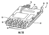
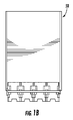
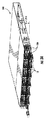
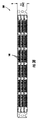
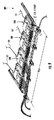
図1Aは、BASE‐8光ファイバモジュール10(以下、モジュール10という)を示し、図2Aおよび図2Bは、モジュール10を用いた機器トレー100(以下、トレーという)を示している。図1Bおよび図1Cは、それぞれ、トレー内に同一のポートを用いた本明細書において開示するトレーおよびシャーシ内にも利用できるBASE‐8・4ポートMTPパネル組立体50およびBASE‐8LCパネル組立体60を示しており、それにより1/3Uトレー内に24ポートMPO密度を実施可能にしまたはトレー内にLC‐LC接続性を実施可能にする。
1A shows a BASE-8 optical fiber module 10 (hereinafter referred to as module 10), and FIGS. 2A and 2B show an equipment tray 100 (hereinafter referred to as tray) using the
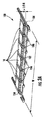
図3A〜図3Dは、トレーを受け入れて支持するシャーシ300を示している。トレーおよび他の機器の使用が1‐Uスペースシャーシに関して示されているが、技術的思想は、これよりも大きなシャーシ、例えば2‐U、4‐Uなどに利用できる。図4および図5は、開示するBASE‐8機器がまた、シャーシ、例えばシャーシ300′の既存の取り付けベースと下位(後方)互換性を有することを示している。図6および図7は、光ファイバパネル組立体をトレー100′内に受けるその使用と一緒に示している。図8〜図10は、幹線ケーブルコネクタのための2つの互いに異なる接続場所を提供することによってデュプレックス伝送からパラレル伝送への移行のためのハイブリッド光ファイバモジュールをトレーおよびシャーシ内におけるその使用と一緒に示している。
3A-3D illustrate a
図1Aは、8個の光接続部を支持したBASE‐8モジュール10を示している。モジュール10は、前端部12および後端部14を有し、光ファイバアダプタ18の直線アレイが前端部12のところに設けられている。これらアダプタは、BASE‐8形態をなして前側部内に幅方向に配置されている。アダプタ18は、LCアダプタであるのが良く、かかるアダプタは、モジュール10内に光ハーネス(見えない)相互間の光接続部を支持している。この実施形態は、全部で8個のLCのための4個のデュプレックスLCアダプタを有するが、これらアダプタは、他の変形例、例えば4個のLCまたは8個のLC内に集団化されるのが良い。
FIG. 1A shows a BASE-8
モジュール10は、内部キャビティを備えたエンクロージャ(符号は付与されていない)を有する。ハーネスは、光ファイバアダプタ18の直線アレイと光ファイバ組立体の後側部との間に光学接続された複数の光ファイバを有する。例えば、MPOアダプタ16が幹線ケーブルの端コネクタとの接続に適した後端部14のところに配置されている。しかしながら、モジュール10の他の変形例、例えば図7にモジュール10′で示されている光接続のために後端部14から延びている例えばピグテールが可能である。
モジュール10は、モジュールを以下に説明するようにトレーに取り付けるためのレール22を更に有する。モジュールは、オプションとして、選択的にモジュールをトレーから取り出したりモジュールをトレーに固定したりするためのレバー24を更に有するのが良い。例えば、レバー24を内方に押してラッチ(符号は付与されていない)をトレーの支持レールから解除することによってラッチ(符号は付与されていない)を外す。レバー24を内方に押すのを容易にするために、指フック(符号は付与されていない)がレバー24に隣接してまたはこの近くに設けられ、従って、レバー24を容易に引くことができ、そしてレバー24を指フックに向かって引き寄せ、それによりラッチをトレーの支持レールと関連した対応の固定機構体に対して側方に変位させてモジュールをトレーから摺動可能に外すことができるようにする。
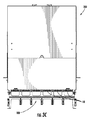
図2Aおよび図2Bは、光ファイバ機器を取り付けるトレー100を示している。トレー100は、開示したようなシャーシ内にまたは他の適当な機器内に取り付けられるのが良い。本明細書で用いられる「取り付け」という用語は、トレー100をシャーシに永続的に、半永続的に、一時的にかつ/あるいは取り外し可能に結合するのに適した任意のコンポーネントまたはコンポーネントの部分を指している。一実施形態では、「取り付け」は、永続的なまたは半永続的な締結具、例えばリベット、ボルト、ねじまたは一構造体を別の構造体に締結するための任意他の適当な機構体(またはこれらの組み合わせ)を用いてトレー100をシャーシに固定することによって実施されるのが良い。代替的にまたは追加的に、「取り付け」は、トレー100をシャーシに固定するための一時的なまたは非永続的な技術を含みまたは具体化しても良い。例えば、ある特定の例示の実施形態では、取り付けは、クリップ、プルタブ、取り外し可能なリベット、プレスクリップ、クリスマスツリー型クリップ、プッシュナット締結具、またはトレー100をシャーシに取り外し可能に結合するのに適した任意他の形式の締結具を用いて実施できる。「取り付け」はまた、トレー100をシャーシに摺動可能に結合するのに適した任意のコンポーネントまたはコンポーネントの組み合わせを含みまたは具体化しても良い。例えば、トレー100は、シャーシに結合された案内レールによりシャーシに取り付けられても良く、案内レールは、トレー100の対応のレールコンポーネントに結合されると、トレー100を支持すると共に案内し、それによりシャーシに対するトレー100の前後方向並進を可能にする。
2A and 2B show a
トレー100は、複数のBASE‐8光ファイバ機器を支持するベース102を有する。例えば、トレーは、モジュール10および/またはパネル組立体400(図6)を有するのが良い。トレーは、トレー100をシャーシ内に可動的に取り付けるためのベース102の1本または2本以上の支持レール104を有する。トレーは、複数のBASE‐8光ファイバ機器をトレー100に可動的に取り付けるためのベースの複数の機器支持レール106を更に有する。支持レールおよび/または機器支持レールは、モジュラーコンポーネントであっても良く、あるいは、所望に応じてトレーのベースと一体に形成されても良い。
The
ベース102は、少なくとも5個のBASE‐8光ファイバ機器を幅W方向に支持するよう構成されている。トレー100は、1/3U‐スペース以下の高さHを有する。トレーは、BASE‐8形態で1/3U‐スペース当たり32個を超える光ファイバ接続部、少なくとも40個の光ファイバ接続部、および48個の光ファイバ接続部の接続部密度を支持することができる。
The
図2Aおよび図2Bに示されているように、トレーは、幅W方向に少なくとも6個のBASE‐8光ファイバ機器を支持するよう構成されている。かくして、モジュール10は、トレー幅Wの1/6以下を用いてトレー100内に取り付けられるよう構成されている。開示するトレーは、例えば図5に示されているシャーシの既存の据え付けられたベース内に据え付け可能であるよう設計されているのが良く、それによりBASE‐8光ファイバ機器を支持する第1のトレーおよびBASE‐12光ファイバ機器を支持する第2のトレーを有するハイブリッドシャーシが形成される。
As shown in FIGS. 2A and 2B, the tray is configured to support at least six BASE-8 fiber optic equipment in the width W direction. Thus, the
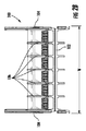
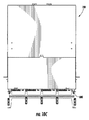
図3A〜図3Dは、複数のトレーを受け入れると共に支持する光ファイバ機器シャーシ300(以下、シャーシという)を示している。図示のように、シャーシ300は、シャーシ内に取り付けられた複数のトレー100を有する。複数のトレーが収納されているシャーシは、一U‐スペース当たり96個を超える光ファイバ接続部、一U‐スペース当たり少なくとも120個の光ファイバ接続部、または一U‐スペース当たり少なくとも144個の光ファイバ接続部の接続部密度を支持することができる。トレー100は、これらトレーを別個独立に動かすことができるような仕方でシャーシ300内に可動的に取り付けられている。さらに、これらモジュールは、トレーのベースに対して別個独立に動くことができるのが良い。シャーシ300は、トレー100の支持レール104を受け入れる支持体を有する。米国特許第8,452,148号明細書は、別個独立に並進可能なモジュールおよびトレーを開示し、米国特許第8,538,226号明細書は、静止位置を有する機器案内およびレールを開示しており、これら米国特許の各々を参照により引用し、その開示内容全体を本明細書の一部とする。
3A-3D illustrate a fiber optic equipment chassis 300 (hereinafter referred to as a chassis) that receives and supports a plurality of trays. As shown, the
一実施形態によれば、シャーシ300は、機器ラックのための1‐Uスペースの標準高さを有するのが良く、かかるシャーシは、このシャーシをラックに固定する取り付け構造体を有する。他の実施形態によれば、シャーシは、機器ラックについて異なるサイズ、例えば2‐Uまたは4‐Uスペース内に取り付けられるのに適した高さを有するのが良い。シャーシ300は、個々のトレー100のための1/3U‐スペースを有する。図3Aに示されているように、底部トレー100は、シャーシ300から延び、頂部の2つのトレー100は、貯蔵位置にある。シャーシが2‐Uスペースシャーシである場合、このシャーシは、6個のトレーを支持し、シャーシが4‐Uスペースシャーシである場合、このシャーシは、12個のトレーを支持する。その結果、3つのトレー100は各々、全部で18個のBASE‐8光ファイバ機器について最大6個までのBASE‐8光ファイバ機器を支持することができる。図3B〜図3Dは、シャーシ300の他の図である。
According to one embodiment, the
BASE‐8モジュールにより、同一のLCデュプレックス密度をBASE‐12トレーおよびシャーシとして達成することができるが、有利には、パネルおよびMPOジャンパを用いた場合、デュプレックス伝送から8心パラレル伝送への移行を可能にするよう100%ファイバ利用率を可能にするよう8心MPOを利用することができる。 The BASE-8 module allows the same LC duplex density to be achieved as a BASE-12 tray and chassis, but advantageously the transition from duplex transmission to 8-core parallel transmission when using panels and MPO jumpers. An 8-core MPO can be utilized to enable 100% fiber utilization to enable.
今日市場に出ている当業界の技術は、大抵8個のファイバ増分まで広く配備されたBASE‐12およびBASE‐24ファイバ技術を利用する変化モジュールを必要とするか、ファイバの全てを利用することができるとは限らないMPO貫通パネルの使用を必要とするかのいずれかである。本明細書において開示する実施形態および技術的思想は、既存の構造化ケーブル布設技術とBASE‐12形態のファイバ心線数のミスマッチを解決すると共にトランシーバとの協働を可能にするマッチしたファイバ心線数を提供する。かくして、本明細書において開示する実施形態および技術的思想は、低減衰率技術と一緒に高密度の容易な変移を可能にする。 The industry technologies on the market today require a change module that utilizes BASE-12 and BASE-24 fiber technology, which is widely deployed, usually up to 8 fiber increments, or utilize all of the fiber It may either require the use of an MPO penetration panel that is not always possible. The embodiments and technical ideas disclosed herein are a matched fiber core that resolves the mismatch between the number of fiber cores in the existing structured cable laying technology and the BASE-12 configuration and enables cooperation with the transceiver. Provides the number of lines. Thus, the embodiments and technical ideas disclosed herein allow for high density easy transitions along with low attenuation techniques.
図4は、モジュール10およびトレー100と従来型BASE‐12光ファイバモジュール1およびBASE‐12機器トレー3の比較結果を示している。図示のように、BASE‐12光ファイバモジュールは、12本のファイバの接続を必要とし、しかも12個のLCポートを支持するアダプタを有する。トレー3は、図示のように4個のBASE‐12光ファイバモジュール1を支持しているのに過ぎない。幾つかの実施形態では、トレー100は、トレー3と類似しており、従って、トレー100は、BASE‐8トレーおよびBASE‐12トレーのハイブリッド形態を支持した共通のシャーシ内に据え付け可能である。
FIG. 4 shows a comparison result between the
図5は、1‐Uスペースシャーシ内に設けられたBASE‐8トレー100とBASE‐12機器トレー3の組み合わせを支持したハイブリッドシャーシ300′を示している。ハイブリッドシャーシ300′は、所望に応じて移動、追加、および変更を伝送プロトコルにもたらすために光ネットワーク内にネットワークオペレータ融通性を提供する一方で、データセンタについてこじんまりとしていてかつ整然としたケーブル配備および引き回しを維持している。
FIG. 5 shows a
開示する技術的思想は、光ネットワークを改造すると共に伝送プロトコルの移行を行うための融通性および可能性をネットワークオペレータに提供するためにトレー内で使用できる他のBASE‐8光ファイバ機器を含む。図6および図7は、融通性をネットワークオペレータに提供するためにトレー内で使用可能な他のBASE‐8光ファイバ機器を示している。図6は、少なくとも1つの前側多心アダプタ418およびパネル組立体400の前端部402を含む光ファイバ組立体400(以下、パネル組立体という)を示している。各多心アダプタは、前側部および後側部を有する。アダプタの各側部は、BASE‐8コネクタを受け入れる。パネル組立体400は、少なくとも1本の光多心ケーブルを挿通状態で受け入れるように構成された少なくとも1つの貫通チャネル410を含む。パネル組立体400は、BASE‐8トレー内で使用でき、このパネル組立体は、トレー幅の1/6以下を用いてトレー内に取り付け可能であるが、パネル組立体はまた、所望ならばBASE‐12トレー3内に嵌まり込むよう寸法決め可能である。さらに、パネル組立体は、シャーシの一部であっても良く、このパネル組立体は、一U‐スペースの1/12以下を占め、例えば、パネル組立体は、シャーシの一部をなすのが良く、このパネル組立体は、一U‐スペースの1/18以下を占める。
The disclosed technical idea includes other BASE-8 fiber optic equipment that can be used in a tray to provide the network operator with the flexibility and potential to modify the optical network and make transmission protocol transitions. FIGS. 6 and 7 illustrate other BASE-8 fiber optic equipment that can be used in the tray to provide network operators with flexibility. FIG. 6 shows an optical fiber assembly 400 (hereinafter referred to as a panel assembly) that includes at least one
パネル組立体400は、BASE‐8コネクタをアダプタ418に据え付けるためにパネル組立体400の下への接近を可能にするパネルに設けられている他の特徴、例えば指接近切欠き420を含むのが良い。貫通チャネル410は、ケーブルを上側からパネル組立体400中に配置することができるよう切欠き411を有するのが良い。さらに、貫通チャネル410は、パネル組立体の前端部402まで延びるのが良く、この貫通チャネルは、ケーブルを上側からパネル組立体400中に配置するための第2の切欠き411を有するのが良い。パネル組立体400は、構造的支持体のためのリブ、トレー内への取り付けのためのパネルレール422、レバー424または他の適当な構造体または特徴部を更に含むのが良い。パネル組立体は、単一のパネルとして構成されても良く、あるいは、パネル組立体は、図示のようにパネル組立体400の前側パネル412と後端部404との間に延びるハウジング401を有しても良い。ハウジング401は、モジュールを形成するよう所望ならばエンクロージャを有することが可能である。
The
パネル組立体400は、少なくとも1つの前側パネル412を有し、少なくとも1つの前側の多心アダプタ418が前側パネル内に設けられる。図6に示されている実施形態では、パネル組立体は、2つの多心アダプタ418のためのそれぞれの2つの前側パネル412を含む。他の実施形態では、パネル組立体400は、少なくとも3つの光ファイバアダプタ418を含むのが良い。
The
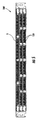
図7は、ピグテールを備えたモジュール10およびモジュール10′と一緒にパネル組立体400を支持した機器トレー100′を示している。トレー100′は、トレー100に似ているが、このトレーにはネットワークオペレータに形態の融通性を提供するための互いに異なるBASE‐8機器が装填されている。トレー100′およびシャーシの前側部に存在するMPO接続性を提供するために単一のトレー内にモジュール10,10′の使用とパネル組立体400の使用を組み合わせている。かくして、トレー100′は、1/3‐Uスペース内に使用できる貫通部と組み合わされたモジュール/パネル組立体を備えたハイブリッドトレーであり、このハイブリッドトレーは、ノースカロライナ州ヒッコリー所在のコーニング・オプティカル・コミュニケーションズ・エルエルシー(Corning Optical Communications LLC)から入手できる既存のEDGEハウジングに使用できるよう下位(後方)互換性がある。
FIG. 7 shows
幹線ケーブル101からのMPOは、図示のようにそれぞれのアダプタ418のところでパネル組立体400の後側部に接続されている。これにより、MTPがハウジングを8心リンクに利用できるようにするようハウジングの前側平面内に提供されるようになる。しかしながら、コネクタがLC接続性中にブレークアウトすることが望ましい場合、モジュール10′のピグテールをMTPパネルの中心に通してパネルの前側部にプラグ接続し、それにより光ネットワーク内においてパラレル伝送からデュプレックス伝送への移行を可能にする。同一の接続性は、MPOジャンパケーブルと共にモジュール10を用いて達成でき、MPOジャンパケーブルは、それぞれの光ファイバアダプタの前側部およびモジュール10の後側部に取り付けられる。
The MPO from the
使用にあたり、少なくとも1つの前側多心アダプタの後側部は、パネル組立体400の後端部404から前端部402に向かって延びる第1の多心光ケーブルに光学結合されるよう構成されており、少なくとも1つの前側多心アダプタの前側部は、パネル組立体400の後端部404から前端部402に向かって延びて、例えばモジュール10を用いたトレー100′の右側に示されている少なくとも1つの貫通チャネル410を通過する第2の多心光ケーブルに光学結合されるよう構成されている。
In use, the rear side of the at least one front multi-fiber adapter is configured to be optically coupled to a first multi-fiber optical cable extending from the
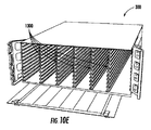
BASE‐8形態に有用である他の光ファイバ機器もまた開示される。図8〜図10Cは、ハイブリッド光ファイバモジュール500(以下、ハイブリッドモジュールという)をトレー組立体600内におけるその使用と一緒に示しており、トレー組立体600は、シャーシ700内に据え付けられて支持されるのが良い。図示のように、ハイブリッドモジュール500は、光ファイバ機器のための4個のスロットを備えた既存のBASE‐12トレー内に嵌まり込み、このトレーは、これがハイブリッドモジュール500を有している点を除き、図4の上側部分に示されているトレーとほぼ同じである。
Other fiber optic equipment useful in the BASE-8 configuration is also disclosed. 8-10C illustrate a hybrid fiber optic module 500 (hereinafter referred to as a hybrid module) along with its use in a
ハイブリッドモジュール500は、BASE‐8MPOアダプタ418を有するハイブリッドモジュールの左側部および他の側部に代表的に示されているデュプレックス伝送のためのMPO/LCブレークアウト部分を両方とも有している。ハイブリッドモジュール500は、前端部502および後端部504を有している。単心コネクタ用アダプタ418の直線アレイが前端部502のところで幅WH方向に配置され、単心アダプタの各々は、前側部および後側部を有している。前側多心アダプタ518が前端部502のところに設けられ、前側多心アダプタは、前側部518Fおよび後側部518Rを有している。後側多心アダプタ516がモジュールの後端部504のところに設けられ、このアダプタ516は、前側部(見えない)および後側部516Rを有している。アダプタ516の前側部は、ハイブリッドモジュール500のエンクロージャの内部キャビティ内に設けられている。複数の光ファイバが単心アダプタのアレイの各々の後側部と後側多心アダプタの前側部との間に光学的に結合されている。幹線ケーブル101の多心コネクタが前側多心コネクタの前側部518Fに接続された多心コネクタとの光結合を可能にするよう多心アダプタ518の後側部518Rか単心コネクタ用アダプタの直線アレイに接続された複数の単心コネクタとの光結合を可能にするよう後側多心アダプタ516の後側部516Rかのいずれかに接続されるのが良い。図示のように、ハイブリッドモジュール500は、複数の光ファイバを内部キャビティ内に包囲すると共にこれらを保護するエンクロージャ(符号が付与されていない)を有する。図示のように、前側多心コネクタ518がエンクロージャの外部に設けられている。かくして、ハイブリッドモジュールは、ジャンパ接続部が容易な接近を可能にするためにトレーまたはシャーシの前側部のところに位置した状態でデュプレックスおよびパラレル伝送を支持し、移行が必要な場合、幹線ケーブルの多心コネクタは、単に、ハイブリッドモジュールの他のアダプタ位置に動かされる。
The
ハイブリッドモジュール500は、8心コネクタとして構成されている単心アダプタ18の直線アレイを支持している。図示のように、アダプタ18は、LCポートとして構成されているが、他のコネクタポートを備えた形態が本発明の技術的思想を用いて可能である。ハイブリッドモジュール500は、ハウジング501を有し、ハウジング501は、前端部502と後端部502との間に部分的に延び、このハウジングは、取り付け構造体を有する。例えば、ハイブリッドモジュール500は、オプションとして、モジュール10と同様にレール522を有するのが良い。同様に、ハイブリッドモジュールは、オプションとして、本明細書において説明するレバー24とほぼ同じレバー524を有するのが良い。
The
ハイブリッドモジュール500は、前側多心アダプタ518の後側部518Rからハイブリッドモジュールの後端部504まで延びる少なくとも1つの貫通チャネル510を更に有する。ハイブリッドモジュール500は、オプションとして、少なくとも1つの貫通チャネル510の近くに位置する少なくとも1つのケーブル管理特徴部、光ケーブルをチャネル内に保持するよう構成された少なくとも1つのケーブル管理特徴部を更に有するのが良い。ハイブリッドモジュール500は、前側多心アダプタの後側部518Rのための指接近切欠き520を更に有するのが良い。ハイブリッドモジュール500は、図示のようにトレー幅W12の1/4以下を用いてトレー600内に取り付けられるよう構成されている。
The
図10A〜図10Cは、ハイブリッドモジュール500がシャーシ700内に据え付けられると共に支持されたトレー組立体を示している。図示のように、シャーシ700は、シャーシ300と同様に1/3‐Uトレースロットを用いて3つのトレーを収容する1‐Uスペースとして高さHを有している。図10Bは、トレー600が装填されたシャーシ700の正面図である。シャーシ300と同様、シャーシ700のトレー600は、別個独立に並進可能である。しかしながら、各トレー600は、4つのハイブリッドモジュール500しか支持していない。かくして、1‐Uスペースを備えたシャーシは、12個のハイブリッドモジュール500を収容するに過ぎないが、100%ファイバ利用率でデュプレックス伝送とパラレル伝送との間の容易な移行経路を提供し、挿入損失予算を増大させない。
10A-10C show a tray assembly in which the
図10Dおよび図10Eは、ある特定の開示した実施形態と一致して互いに異なる4‐Uシャーシ具体化例のそれぞれの前から見た斜視図である。例えば、図10Dは、12個の1/3(またはそれ以下)U‐高さトレーを備えた4‐Uシャーシ具体化例を示しており、各トレーは、6個の別個独立に並進可能なモジュールを保持するよう構成されている。図10Eは、シャーシの頂部からシャーシの底部まで垂直に位置決めされた1つまたは2つ以上の仕切り部材を有する4‐Uシャーシ具体化例を示している。図10Eに示されているように、仕切り部材は、個々のモジュールに摺動可能に係合するよう構成されるのが良く、それによりトレーの必要性がなくなっている。仕切り部材の各々は、レールをモジュールの側部上に支持する複数の案内レールを含みまたは具体化するのが良い。 10D and 10E are perspective views from the front of each of the different 4-U chassis embodiments consistent with certain disclosed embodiments. For example, FIG. 10D shows a 4-U chassis embodiment with twelve 1/3 (or less) U-height trays, each tray being six independently translatable. Configured to hold modules. FIG. 10E illustrates a 4-U chassis embodiment having one or more partition members positioned vertically from the top of the chassis to the bottom of the chassis. As shown in FIG. 10E, the partition member may be configured to slidably engage the individual modules, thereby eliminating the need for a tray. Each of the partition members may include or embody a plurality of guide rails that support the rails on the sides of the module.
図11Aおよび図11Bは、それぞれ、ある特定の開示した実施形態と一致したBASE‐8光ファイバモジュール10の変形実施形態の後部の斜視図およびBASE‐8光ファイバパネル400の変形実施形態の前部の斜視図である。図11Aに示されているように、図1Aと同様、モジュール10は、前端部および後端部を有するのが良く、光ファイバアダプタ18の直線アレイが前端部12のところに設けられている。アダプタは、BASE‐8形態で前側部内に幅方向に配置されている。アダプタ18は、LCアダプタであるのが良く、これらアダプタは、モジュール10内の光ハーネス(見えない)相互間の光結合を支持する。図11Aに示されている実施形態は、全部で8個のLCのための4個のデュプレックスACアダプタを有するが、アダプタは、他の変形例、例えば4個のLCまたは8個のLC内に集団化されても良い。
FIGS. 11A and 11B are perspective views of the rear of a modified embodiment of a BASE-8
モジュール10は、内部キャビティを備えたエンクロージャ(符号は付与されていない)を更に有するのが良い。ハーネスは、光ファイバアダプタ18の直線アレイと光ファイバ組立体の後側部との間に光結合された複数の光ファイバを有する。例えば、MPOアダプタ16は、幹線ケーブルの8心コネクタとの接続に適した後端部14のところに設けられている。しかしながら、モジュール10の他の変形例、例えば光結合を可能にするために後端部14から延びるピグテールが採用可能である。
The
モジュール10は、このモジュールを以下に説明するようにトレーに取り付けるためのレール22を更に有する。モジュール10は、選択的にモジュールをトレーから取り出したりモジュールをトレーに固定したりするためのレバー24を更に有するのが良い。例えば、レバー24を内方に押してラッチ(符号は付与されていない)をトレーの支持レールから解除することによってラッチ(符号は付与されていない)を外す。レバー24の作動を容易にするため、指タブ1112がモジュール10の後部に設けられるのが良く、この指タブは、レバー24から横に所定の距離離れたところに位置決めされるのが良い。図11Aに示された例示の実施形態によれば、指タブ1112は、レバー24から見てモジュールの互いに反対側の側部にかつファイバアダプタ16の外部に位置決めされるのが良く、それによりアダプタ10のための追加の遮蔽および保護作用を提供する。一実施形態によれば、図11Aに示されているように、アダプタ16(MTPアダプタとして示されている)は、内部光ファイバハーネスの好都合の引き回しを可能にするようモジュール10の縁部寄りに位置決めされるのが良い。他の実施形態では、アダプタ16は、特定のモジュールの所望の引き回し形態に応じて、モジュール10の後部に沿って巧妙に位置決めされるのが良い。
レバー24の作動の際、レバー24と指タブ1112を互いに向かい合って押し、レバー24を指タブ1112に引き寄せ、それによりラッチをトレーの支持レールと関連した対応の固定機構体に対して側方に変位させてモジュールをトレーから摺動可能に取り外すことができる。幾つかの実施形態によれば、モジュール10は、レバー24の側方変位を制限してレバー24に加えられる過剰の力を制限しまたは減少させる機構体を提供するようレバー24に隣接してまたはこの近くに位置決めされた停止タブ1110を更に有するのが良い。幾つかの実施形態では、レバー24、指タブ1112または停止タブ1110のうちの1つまたは2つ以上は、1つまたは2つ以上の表面上に「ギザギザ」付きであるのがよく、それにより作動中における良好なグリップを提供する。
Upon actuation of the
図11Bは、例示の光ファイバパネル440を示している。図11Bから理解できるように、パネル組立体400は、少なくとも1つの光多心ケーブルを挿通状態で受け入れるよう構成された少なくとも1つの貫通チャネルを含む。パネル組立体400は、BASE‐8トレー内に使用できると共にトレー幅の1/6以下を用いてトレー内に取り付け可能であるが、このパネル組立体はまた、所望ならばBASE‐12トレー3内に嵌まり込むよう寸法決め可能である。さらに、パネル組立体はシャーシの一部であっても良く、このパネルは、一U‐スペースの1/12以下を占めるのが良く、例えば、パネル組立体は、一U‐スペースの1/18以下を占めることができる。
FIG. 11B shows an exemplary fiber optic panel 440. As can be appreciated from FIG. 11B, the
パネル組立体400は、パネルに設けられていてBASE‐8コネクタをアダプタ418に据え付けるためにパネル組立体400の下への接近を可能にする他の特徴部、例えば指接近切欠き(図11Bに明示的には示されていない)を有するのが良い。貫通チャネルは、ケーブルをパネル組立体400内に上側から配置することができるよう切欠きを有するのが良い。さらに、貫通チャネルは、パネル組立体の前端部まで延びるのが良く、この貫通チャネルは、ケーブルをパネル組立体400内に上側から配置するための第2の切欠きを有するのが良い。パネル組立体400は、構造的支持のためのリブ、トレー内への取り付けのためのパネルレール422、レバー424、停止タブ1110、および/または指タブ1112または他の適当な構造体もしくは特徴部を更に含むのが良い。レバー424、停止タブ1110、および指タブ1112は、図11Aを参照して上述したのと同様に機能する。パネル組立体は、単一パネルとして構成されても良く、あるいは、図示のようにパネル組立体400の前側パネルと後端部との間に延びるハウジングを有しても良い。ハウジングは、モジュールを形成するよう所望ならばエンクロージャを有することが可能である。
The
パネル組立体400は、少なくとも1つの前側パネルを有するのが良く、少なくとも1つの前側多心アダプタ418が前側パネル内に設けられる。図11Bに示された実施形態では、パネル組立体は、4つの多心アダプタ418についてそれぞれ4つの前側パネルを有する。他の実施形態では、パネル組立体400は、3枚以下または5枚以上のパネルを含むのが良い。
The
図12は、ある特定の開示した実施形態に従ってトレー100で用いられる例示の取り付けレール106の斜視図である。図13は、ある特定の開示した実施形態に一致して図12の例示の取り付けレール106を備えた例示のトレー100の斜視図である。図12の実施形態に示されているように、取り付けレール106の垂直ビームの下面で取り付けレール106の前のところの左側縁部と右側縁部との両方上に設けられた溝1220および面取り部1230を有するのが良い。一実施形態によれば、溝1220は、取り付けレール106の幅全体を横切る単一の溝を具体化している。代替的にまたは追加的に、取り付けレール106は、多数の溝1220(例えば、2つ)を有するのが良く、これら溝のうちの1つは、所定の長さ(例えば、垂直ビームの全幅の1/2未満)にわたり、垂直ビームの右外側縁部から垂直ビームの中心に向かって側方に延び、また、これら溝のうちの1つは、所定の長さ(例えば、垂直ビームの全幅の1/2未満)にわたり、垂直ビームの左外側縁部から垂直ビームの中心に向かって側方に延びている。面取り部1230は、トレー100の前からのモジュールおよびパネルの容易な案内および装填を可能にするのが良く、モジュールまたはパネルの片手の装填作業を可能にする。
FIG. 12 is a perspective view of an exemplary mounting
図13は、モジュール10、パネル400、およびこれらの組み合わせのうちの1つまたは2つ以上を載せる図12の多数の取り付けレール106を備えたトレー100の前から見た拡大斜視図である。図13に示されているように、トレー100は、1つまたは2つ以上の接近穴1320を有するのが良い。一実施形態によれば、接近穴1320は、トレーの底部に設けられる長方形の開口部を含むのが良くまたは具体化するのが良い。ある特定の実施形態では、接近穴1320は、下に位置するトレーからのモジュール10への指による接近を可能にすると共にパネル400に設けられているシャッターが90°を超えて回転して開くのに十分幅が広いように作られるのが良い。接近穴1320は、BASE‐8モジュール10およびパネル400のフットプリントに対応するよう寸法決めされているが、ハイブリッドパネルかBASE‐12パネルおよびBASE‐8(またはこれらの任意の組み合わせ)の両方かのいずれかの幅をとるよう寸法決めされても良い。図13に示されているように、トレー100は、複数のケーブル引き回し案内1310を更に有するのが良く、これらケーブル引き回し案内の各々は、トレー100のそれぞれの引き回し案内支持フィンガ(別々には符号が付与されていない)の頂部に取り付けられる。
13 is an enlarged perspective view from the front of the
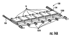
図14A〜図14Cは、光ファイバ機器を取り付けるための例示のトレー100の前から見た斜視図、平面図、および拡大図である。トレー100は、開示したようなシャーシ内にまたは他の適当な機器内に取り付けられるのが良い。本明細書で用いられる「取り付け」という用語は、トレー100をシャーシに永続的に、半永続的に、一時的にかつ/あるいは取り外し可能に結合するのに適した任意のコンポーネントまたはコンポーネントの部分を指している。一実施形態では、「取り付け」は、永続的なまたは半永続的な締結具、例えばリベット、ボルト、ねじまたは一構造体を別の構造体に締結するための任意他の適当な機構体(またはこれらの組み合わせ)を用いてトレー100をシャーシに固定することによって実施されるのが良い。代替的にまたは追加的に、「取り付け」は、トレー100をシャーシに固定するための一時的なまたは非永続的な技術を含みまたは具体化しても良い。例えば、ある特定の例示の実施形態では、取り付けは、クリップ、プルタブ、取り外し可能なリベット、プレスクリップ、クリスマスツリー型クリップ、プッシュナット締結具、またはトレー100をシャーシに取り外し可能に結合するのに適した任意他の形式の締結具を用いて実施できる。「取り付け」はまた、トレー100をシャーシに摺動可能に結合するのに適した任意のコンポーネントまたはコンポーネントの組み合わせを含みまたは具体化しても良い。例えば、トレー100は、シャーシに結合された案内レールによりシャーシに取り付けられても良く、案内レールは、トレー100の対応のレールコンポーネントに結合されると、トレー100を支持すると共に案内し、それによりシャーシに対するトレー100の前後方向並進を可能にする。
14A-14C are a perspective view, a plan view, and an enlarged view, as seen from the front, of an
トレー100は、複数のBASE‐8光ファイバ機器を支持するベースを有する。例えば、トレーは、モジュール10および/またはパネル組立体400(図11B)を有するのが良い。トレーは、トレー100をシャーシ内に可動的に取り付けるためのベース102の1本または2本以上の支持レール104を有する。トレーは、複数のBASE‐8光ファイバ機器をトレー100に可動的に取り付けるためのベースの複数の機器支持レール106を更に有する。支持レールおよび/または機器支持レールは、モジュラーコンポーネントであっても良く、あるいは、所望に応じてトレーのベースと一体に形成されても良い。
The
ベース102は、少なくとも5個のBASE‐8光ファイバ機器を幅W方向に支持するよう構成されている。トレー100は、1/3U‐スペース以下の高さHを有する。トレーは、BASE‐8形態で1/3U‐スペース当たり32個を超える光ファイバ接続部、少なくとも40個の光ファイバ接続部、および48個の光ファイバ接続部の接続部密度を支持することができる。
The
図14A〜図14Cに示されているように、トレー100は、幅W方向に少なくとも6個のBASE‐8光ファイバ機器を支持するよう構成されている。かくして、モジュール10は、トレー幅Wの1/6以下を用いてトレー100内に取り付けられるよう構成されている。開示するトレーは、例えば図5に示されているシャーシの既存の据え付けられたベース内に据え付け可能であるよう設計されているのが良く、それによりBASE‐8光ファイバ機器を支持する第1のトレーおよびBASE‐12光ファイバ機器を支持する第2のトレーを有するハイブリッドシャーシが形成される。
As shown in FIGS. 14A-14C, the
図15は、ある特定の開示した実施形態と一致して伸長(「引き出し」)位置にある下側トレーおよび完全引っ込み(「収納」)位置にある下側トレーを含む例示のシャーシ組立体の平面図である。図15に示されているように、トレー100は、複数の対向可能なトレープルタブ(符号が付与されていない)を有するのが良く、これらプルタブの各々は、トレー100のそれぞれの前側横のコーナー部から突き出ている。隙間がトレーのレール上のモジュール解除レバーへの下からの指の接近を可能にするよう構成されており、他方、指によりプルタブ中へ深いところまで接近できる。一実施形態によれば、標的指/親指‐先端部隙間は、約13mmである。
FIG. 15 is a plan view of an exemplary chassis assembly that includes a lower tray in an extended (“drawer”) position and a lower tray in a fully retracted (“storage”) position, consistent with certain disclosed embodiments. FIG. As shown in FIG. 15, the
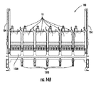
図16Aおよび図16Bは、ある特定の開示した実施形態に従って機器トレーのそれぞれの具体化例で用いられる金属製の支持構造体の変形実施形態の平面図である。図16Aおよび図16Bに示されているように、トレー100は、ケーブル引き回し案内1310を支持するためにトレー100の前に向かって外方に突き出た複数の引き回し案内支持フィンガ(別々には符号が付与されていない)を有するのが良い。引き回し案内支持フィンガに対応したトレー100の金属製支持構造体は、モジュール10、パネル400またはシャーシと関連した他の機器への最適な手および指による接近を可能にする厚さおよび長さのものである。同様に、トレー100の互いに反対側の側縁からトレー100の後部に向かって延びるトレー100のトレーレール取り付け支持体(別々には符号が付与されていない)もまた、親指解除左後側位置および指タブ右後側位置への接近を可能にする厚さおよび長さのものである。
16A and 16B are plan views of alternative embodiments of a metal support structure used in each embodiment of an equipment tray in accordance with certain disclosed embodiments. As shown in FIGS. 16A and 16B, the
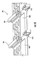
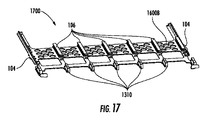
図17は、ある特定の開示した実施形態と一致してレール案内およびジャンパ引き回し案内を有する例示の機器トレーの前から見た等角斜視図である。図18は、ある特定の開示した実施形態による例示のジャンパ引き回し案内の横から見た斜視図である。 FIG. 17 is an isometric view from the front of an exemplary equipment tray having rail guidance and jumper routing guidance consistent with certain disclosed embodiments. FIG. 18 is a side perspective view of an exemplary jumper routing guide according to certain disclosed embodiments.
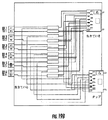
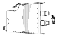
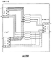
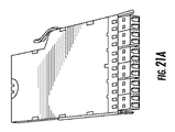
図19A、図19Bおよび図19Cは、それぞれ、MTPポート「タップ」機能を備えた例示のLC‐MTPモジュールの正面から見た斜視図(BASE‐12に関する)、概略配線図(BASE‐12について)および概略配線図(BASE‐8について)である。図20Aおよび図20Bは、それぞれ、MTPポート「タップ」機能を備えた例示のBASE‐12およびBASE‐8MTP‐MTPモジュールの正面から見た斜視図および概略配線図である。図21A、図21Bおよび図21Cは、例示のLC‐LCポート「タップ」機能の正面から見た斜視図(BASE‐12について)、概略配線図(BASE‐12について)および概略配線図(BASE‐8について)である。 19A, 19B, and 19C are perspective views (with respect to BASE-12) and schematic wiring diagrams (with respect to BASE-12), respectively, of an exemplary LC-MTP module with an MTP port “tap” function. And a schematic wiring diagram (for BASE-8). 20A and 20B are a perspective view and a schematic wiring diagram, respectively, as seen from the front of an exemplary BASE-12 and BASE-8MTP-MTP module with MTP port “tap” functionality. 21A, 21B and 21C are perspective views (for BASE-12), schematic wiring diagram (for BASE-12) and schematic wiring diagram (BASE-) for the exemplary LC-LC port “tap” function as viewed from the front. 8).
注目されるべきこととして、ある特定の実施形態は、各トレー100がシャーシの幅全体を占めた状態で図示されると共に説明されているが、本明細書において説明する実施形態は、複数のトレーを用いてシャーシの幅を占めるために用いられる実施形態を想定していることが考えられる。例えば、各々が1‐Uシャーシの幅(またはそれ以下)および高さの1/3(またはそれ以下)を占めるよう設計された3個のトレーを有するのではなく、シャーシは、各々が1‐Uシャーシの幅の1/2(またはそれ以下)および高さの1/3(またはそれ以下)を占めるよう設計された6個のトレーを備えた形態を支持するよう設計されるのが良い。これら実施形態では、シャーシは、シャーシの頂部からシャーシのほぼ水平の中点のところに位置するシャーシの底部まで垂直に位置決めされた1つまたは2つ以上の仕切り部材を有するのが良く、仕切り部材は、トレーの側部上にレールを支持する複数の案内レールを有する。かかる設計例は、同じ列に属する互いに異なるサイズのBASEモジュールを支持するための融通性を提供する。例えば、この列の一方の半部は、3つのBASE‐8モジュールを支持するよう構成されるのが良く、列の他方の半部は、2つのBASE‐12モジュールを収容するよう構成されるのが良く、それにより大きなカスタマイズの度合いの実現が可能である。
It should be noted that although certain embodiments are illustrated and described with each
開示した技術的思想および光ファイバ機器は、ネットワークオペレータが要望に応じてデュプレックス伝送とパラレル伝送との間で移行するよう必要に応じて光ネットワークアーキテクチャを改造するための融通性を提供する。さらに、トレーおよび組立体は、ネットワークオペレータがすでに用いている場合がある据え付け状態のシャーシベース内に嵌まり込むよう下位(後方)互換性があるのが良い。 The disclosed technical ideas and fiber optic equipment provide the flexibility for network operators to adapt the optical network architecture as needed to transition between duplex and parallel transmission as desired. In addition, the tray and assembly should be backward (backward) compatible to fit within an installed chassis base that may already be used by the network operator.
別段の指定がなければ、本明細書において記載した方法は、このステップが特定の順序で実施されることを必要とするものと解することは意図されていない。したがって、方法クレームがそのステップの辿るべき順序を実際に記載していない場合またはステップが特定の順序に限定されるべきことが特許請求の範囲の記載または本明細書において具体的に記載されていない場合、任意特定の順序を推定することは意図されていない。 Unless otherwise specified, the methods described herein are not intended to be interpreted as requiring that the steps be performed in a particular order. Thus, it is not specifically stated in the claims or herein that a method claim does not actually describe the order in which the steps should be followed or that the steps should be limited to a particular order. In any case, it is not intended to estimate any particular order.
当業者であれば理解されるように、開示した実施形態の精神および範囲から逸脱することなく種々の改造および変形を行うことができる。実施形態の精神および実質を組み込んだ開示した実施形態の改造例、コンビネーション、サブコンビネーションおよび変形例は、当業者に想到できるので、解した実施形態は、特許請求の範囲に記載された本発明の範囲およびその均等範囲内に含まれるあらゆる形態を含むものと解されるべきである。 It will be appreciated by those skilled in the art that various modifications and variations can be made without departing from the spirit and scope of the disclosed embodiments. Modifications, combinations, sub-combinations and variations of the disclosed embodiments incorporating the spirit and substance of the embodiments will occur to those skilled in the art, and thus understood embodiments of the present invention are described in the claims. It should be construed to include all forms included within a range and its equivalents.
Claims (21)
複数のBASE‐8型光ファイバ機器を支持するベースと、
前記トレーを光ファイバ機器シャーシ内に可動的に設置するための前記ベースの1本または2本以上の支持レールと、
前記複数のBASE‐8型光ファイバ機器を前記トレーに可動的に取り付けるための前記ベースの複数の機器支持レールとを有する、トレー。 A tray for mounting fiber optic equipment, the tray being
A base supporting a plurality of BASE-8 type optical fiber devices;
One or more support rails of the base for movably installing the tray in a fiber optic equipment chassis;
A tray having a plurality of base support rails for movably attaching the plurality of BASE-8 type fiber optic equipment to the tray.
前記光ファイバ組立体の前端部のところに設けられた前側パネルと、
BASE‐8形態で前記前側パネル内に幅方向に配置された光ファイバアダプタの直線アレイとを含み、前記光ファイバアダプタは、前記複数の光ファイバアダプタと前記光ファイバ組立体の後端部との間に光学的に結合された複数の光ファイバを支持するよう構成され、
前記光ファイバ組立体は、トレー内に設置されて前記トレーの幅の1/6以下を占めるよう構成されている、光ファイバ組立体。 An optical fiber assembly comprising:
A front panel provided at a front end of the optical fiber assembly;
A linear array of optical fiber adapters arranged in the width direction in the front panel in a BASE-8 configuration, wherein the optical fiber adapter includes a plurality of optical fiber adapters and a rear end of the optical fiber assembly. Configured to support a plurality of optical fibers optically coupled therebetween,
The optical fiber assembly is configured to be installed in a tray and occupy 1/6 or less of the width of the tray.
前側部を備えたハウジングと、
BASE‐8形態で前記前側部内に幅方向に配置された光ファイバアダプタの直線アレイとを含み、前記光ファイバアダプタは、前記光ファイバアダプタと前記光ファイバ組立体の後側部との間に光学的に結合された複数の光ファイバを支持するよう構成され、
前記光ファイバモジュールは、前記トレーの幅の1/6以下を用いてトレー中に設置されるよう構成されている、光ファイバモジュール。 An optical fiber module,
A housing with a front side;
A linear array of fiber optic adapters arranged in a width direction within the front side in a BASE-8 configuration, wherein the fiber optic adapter is optically coupled between the fiber optic adapter and a rear side of the fiber optic assembly. Configured to support a plurality of optically coupled optical fibers,
The optical fiber module is configured to be installed in a tray using 1/6 or less of the width of the tray.
Applications Claiming Priority (9)
| Application Number | Priority Date | Filing Date | Title |
|---|---|---|---|
| US201462043797P | 2014-08-29 | 2014-08-29 | |
| US201462043794P | 2014-08-29 | 2014-08-29 | |
| US201462043802P | 2014-08-29 | 2014-08-29 | |
| US62/043,794 | 2014-08-29 | ||
| US62/043,797 | 2014-08-29 | ||
| US62/043,802 | 2014-08-29 | ||
| US201562132872P | 2015-03-13 | 2015-03-13 | |
| US62/132,872 | 2015-03-13 | ||
| PCT/US2015/047661 WO2016033577A1 (en) | 2014-08-29 | 2015-08-31 | Fiber optic solutions for migration between duplex and parallel multi-fiber solutions |
Publications (1)
| Publication Number | Publication Date |
|---|---|
| JP2017529566A true JP2017529566A (en) | 2017-10-05 |
Family
ID=54140663
Family Applications (4)
| Application Number | Title | Priority Date | Filing Date |
|---|---|---|---|
| JP2017511834A Pending JP2017526012A (en) | 2014-08-29 | 2015-08-31 | Optical fiber technology that can be transferred between duplex multi-core technology and parallel multi-core technology |
| JP2016546073A Pending JP2017529548A (en) | 2014-08-29 | 2015-08-31 | Optical fiber technology that can be transferred between duplex multi-core technology and parallel multi-core technology |
| JP2017511849A Pending JP2017526013A (en) | 2014-08-29 | 2015-08-31 | Optical fiber technology that can be transferred between duplex multi-core technology and parallel multi-core technology |
| JP2017511838A Pending JP2017529566A (en) | 2014-08-29 | 2015-08-31 | Optical fiber technology that can be transferred between duplex multi-core technology and parallel multi-core technology |
Family Applications Before (3)
| Application Number | Title | Priority Date | Filing Date |
|---|---|---|---|
| JP2017511834A Pending JP2017526012A (en) | 2014-08-29 | 2015-08-31 | Optical fiber technology that can be transferred between duplex multi-core technology and parallel multi-core technology |
| JP2016546073A Pending JP2017529548A (en) | 2014-08-29 | 2015-08-31 | Optical fiber technology that can be transferred between duplex multi-core technology and parallel multi-core technology |
| JP2017511849A Pending JP2017526013A (en) | 2014-08-29 | 2015-08-31 | Optical fiber technology that can be transferred between duplex multi-core technology and parallel multi-core technology |
Country Status (10)
| Country | Link |
|---|---|
| US (5) | US20160062055A1 (en) |
| EP (4) | EP3186671A1 (en) |
| JP (4) | JP2017526012A (en) |
| KR (1) | KR20170048241A (en) |
| CN (4) | CN107076935A (en) |
| AU (3) | AU2015308577A1 (en) |
| BR (3) | BR112017004090A2 (en) |
| CA (4) | CA2959509A1 (en) |
| IL (2) | IL245175A0 (en) |
| WO (4) | WO2016033577A1 (en) |
Cited By (1)
| Publication number | Priority date | Publication date | Assignee | Title |
|---|---|---|---|---|
| US10481331B2 (en) | 2018-02-13 | 2019-11-19 | Fujikura Ltd. | Reinforcement sleeve |
Families Citing this family (37)
| Publication number | Priority date | Publication date | Assignee | Title |
|---|---|---|---|---|
| US9690065B2 (en) | 2014-09-12 | 2017-06-27 | Panduit Corp. | High density fiber enclosure and method |
| USD901390S1 (en) * | 2015-03-16 | 2020-11-10 | Optiworks, Inc. | High-density optical module system |
| US9500833B1 (en) * | 2015-05-07 | 2016-11-22 | Alliance Fiber Optic Products, Inc. | Optical fiber module rack system |
| DE102015118338A1 (en) | 2015-10-27 | 2017-04-27 | Reichle & De-Massari Ag | Patch panel device and modular system for producing a patch panel device |
| US20170153399A1 (en) * | 2015-11-30 | 2017-06-01 | Corning Optical Communications LLC | Modular interface converter for fiber optic cassettes and modules |
| US10215944B2 (en) * | 2016-06-30 | 2019-02-26 | Panduit Corp. | Modular fiber optic tray |
| WO2018089359A1 (en) | 2016-11-08 | 2018-05-17 | Telect, Inc. | Fiber cassette |
| US10670822B2 (en) | 2017-06-28 | 2020-06-02 | Afl Telecommunications Llc | High density patch panel with modular cassettes |
| US10359577B2 (en) | 2017-06-28 | 2019-07-23 | Corning Research & Development Corporation | Multiports and optical connectors with rotationally discrete locking and keying features |
| US11668890B2 (en) | 2017-06-28 | 2023-06-06 | Corning Research & Development Corporation | Multiports and other devices having optical connection ports with securing features and methods of making the same |
| AU2017421285B2 (en) | 2017-06-28 | 2024-03-28 | Corning Research & Development Corporation | Compact fiber optic connectors, cable assemblies and methods of making the same |
| CA3221590C (en) | 2017-10-03 | 2024-03-19 | Belden Canada Ulc | Modular fiber optic cassette, system and method |
| JP6576411B2 (en) * | 2017-11-08 | 2019-09-18 | 株式会社フジクラ | Optical wiring unit |
| CA3030399A1 (en) * | 2018-01-16 | 2019-07-16 | Belden Canada Inc. | Fiber optic cassette system with reversible cassettes |
| US10416406B1 (en) * | 2018-03-01 | 2019-09-17 | Afl Telecommunications Llc | Communications module housing |
| US10641967B1 (en) * | 2018-11-16 | 2020-05-05 | Corning Research & Development Corporation | Multiport assemblies including a modular adapter support array |
| DK3660564T3 (en) * | 2018-11-28 | 2023-04-24 | Reichle & De Massari Fa | CABLE MANAGEMENT SYSTEM |
| EP3660565A1 (en) * | 2018-11-28 | 2020-06-03 | Reichle & De-Massari AG | Cable management system |
| CN109541759A (en) * | 2019-01-15 | 2019-03-29 | 南京普天天纪楼宇智能有限公司 | A kind of optic module insert box that high density is easy to plug |
| US10969554B2 (en) | 2019-04-01 | 2021-04-06 | Afl Telecommunications Llc | Fiber optic tray systems |
| EP4236343A3 (en) | 2019-04-17 | 2023-10-18 | Afl Ig Llc | Patch panel with lifting cassette removal |
| CN111142202A (en) * | 2019-05-17 | 2020-05-12 | 深圳市飞博康光通讯技术有限公司 | High-density optical fiber distribution tray |
| CN110673282A (en) * | 2019-09-25 | 2020-01-10 | 深圳长飞智连技术有限公司 | Ultrahigh-density modular optical fiber distribution frame system |
| US11487073B2 (en) | 2019-09-30 | 2022-11-01 | Corning Research & Development Corporation | Cable input devices having an integrated locking feature and assemblies using the cable input devices |
| EP3805827A1 (en) | 2019-10-07 | 2021-04-14 | Corning Research & Development Corporation | Fiber optic terminals and fiber optic networks having variable ratio couplers |
| US11036020B2 (en) | 2019-10-10 | 2021-06-15 | Telect, Inc. | Outside plant data communication systems |
| US11184688B2 (en) * | 2019-11-04 | 2021-11-23 | Cisco Technology, Inc. | Minimal touch post for multi-layer cable routing |
| WO2021091970A1 (en) | 2019-11-07 | 2021-05-14 | Panduit Corp. | 12 fiber mpo to 16 fiber mpo conversion module |
| US11650388B2 (en) | 2019-11-14 | 2023-05-16 | Corning Research & Development Corporation | Fiber optic networks having a self-supporting optical terminal and methods of installing the optical terminal |
| US11536921B2 (en) | 2020-02-11 | 2022-12-27 | Corning Research & Development Corporation | Fiber optic terminals having one or more loopback assemblies |
| CN113885138A (en) * | 2020-07-01 | 2022-01-04 | 罗森伯格高频技术有限及两合公司 | Optical fiber module, optical fiber module kit and optical distribution frame |
| EP4214081A1 (en) | 2020-09-18 | 2023-07-26 | Nubis Communications, Inc. | Data processing systems including optical communication modules |
| CA3198375A1 (en) | 2020-10-07 | 2022-04-14 | Nubis Communications, Inc. | Data processing systems including optical communication modules |
| US20230018654A1 (en) * | 2021-06-17 | 2023-01-19 | Nubis Communications, Inc. | Communication systems having pluggable modules |
| US20230324638A1 (en) * | 2022-04-12 | 2023-10-12 | Telect, Inc. | Cable routing storage assemblies for data communication systems |
| JP2024005898A (en) | 2022-06-30 | 2024-01-17 | 三和テクノロジーズ株式会社 | Optical connector adapter integrated cassette case |
| CN116520519B (en) * | 2023-04-07 | 2024-03-19 | 合肥比洋通信科技有限公司 | OXC all-optical backboard |
Family Cites Families (22)
| Publication number | Priority date | Publication date | Assignee | Title |
|---|---|---|---|---|
| US6932514B2 (en) * | 2003-01-21 | 2005-08-23 | Furukawa Electric North America, Inc. | High density modular backplane connector for fiber optics |
| US7636506B2 (en) * | 2003-05-13 | 2009-12-22 | Alcatel-Lucent Usa Inc. | Optical fiber management in a chassis-based network system |
| US7218827B2 (en) * | 2004-06-18 | 2007-05-15 | Adc Telecommunications, Inc. | Multi-position fiber optic connector holder and method |
| US7412147B2 (en) * | 2005-03-15 | 2008-08-12 | Adc Telecommunications, Inc. | Normal through optical panel |
| ES2533966T3 (en) * | 2007-09-06 | 2015-04-16 | Prysmian S.P.A. | Modular system and procedures for connecting an external communication network with a building user network |
| US7945135B2 (en) * | 2008-08-29 | 2011-05-17 | Corning Cable Systems Llc | Telescoping fiber optic module and related equipment |
| US8452148B2 (en) | 2008-08-29 | 2013-05-28 | Corning Cable Systems Llc | Independently translatable modules and fiber optic equipment trays in fiber optic equipment |
| WO2010059623A1 (en) * | 2008-11-21 | 2010-05-27 | Adc Telecommunications, Inc. | Fiber optic telecommunications module |
| US20100129030A1 (en) * | 2008-11-24 | 2010-05-27 | Giraud William J | Universal Optical Splitter Modules and Related Mounting Brackets, Assemblies and Methods |
| US8538226B2 (en) | 2009-05-21 | 2013-09-17 | Corning Cable Systems Llc | Fiber optic equipment guides and rails configured with stopping position(s), and related equipment and methods |
| US8712206B2 (en) * | 2009-06-19 | 2014-04-29 | Corning Cable Systems Llc | High-density fiber optic modules and module housings and related equipment |
| US7945136B2 (en) * | 2009-06-19 | 2011-05-17 | Corning Cable Systems Llc | Mounting of fiber optic cable assemblies within fiber optic shelf assemblies |
| CA2765835A1 (en) * | 2009-06-22 | 2011-01-13 | Corning Cable Systems Llc | Fiber optic cable parking device |
| US8406597B2 (en) * | 2010-02-16 | 2013-03-26 | Commscope, Inc. Of North Carolina | Intelligent fiber optic adapter mounting structures that receive and correctly position multiple types of fiber optic adapters and related adapter collars and bulkheads |
| CA2737716A1 (en) * | 2010-04-30 | 2011-10-30 | Corning Cable Systems Llc | Module with adapter side entry opening |
| US9279951B2 (en) * | 2010-10-27 | 2016-03-08 | Corning Cable Systems Llc | Fiber optic module for limited space applications having a partially sealed module sub-assembly |
| US9116324B2 (en) * | 2010-10-29 | 2015-08-25 | Corning Cable Systems Llc | Stacked fiber optic modules and fiber optic equipment configured to support stacked fiber optic modules |
| US9057859B2 (en) * | 2011-10-07 | 2015-06-16 | Adc Telecommunications, Inc. | Slidable fiber optic connection module with cable slack management |
| US8676022B2 (en) * | 2012-04-13 | 2014-03-18 | Corning Cable Systems Llc | Adapter for fiber optic connectors |
| US9250409B2 (en) * | 2012-07-02 | 2016-02-02 | Corning Cable Systems Llc | Fiber-optic-module trays and drawers for fiber-optic equipment |
| US20140140660A1 (en) * | 2012-11-19 | 2014-05-22 | Scott Eaker Buff | Polarity scheme for parallel-optics data transmission |
| US20150162982A1 (en) * | 2013-12-06 | 2015-06-11 | Corning Cable Systems Llc | Fiber optic assemblies for tapping live optical fibers in fiber optic networks employing parallel optics |
-
2015
- 2015-08-31 EP EP15766275.0A patent/EP3186671A1/en not_active Withdrawn
- 2015-08-31 CN CN201580003045.7A patent/CN107076935A/en active Pending
- 2015-08-31 JP JP2017511834A patent/JP2017526012A/en active Pending
- 2015-08-31 CN CN201580051498.7A patent/CN107076936A/en active Pending
- 2015-08-31 BR BR112017004090A patent/BR112017004090A2/en not_active Application Discontinuation
- 2015-08-31 CN CN201580051571.0A patent/CN106716206A/en active Pending
- 2015-08-31 AU AU2015308577A patent/AU2015308577A1/en not_active Abandoned
- 2015-08-31 WO PCT/US2015/047661 patent/WO2016033577A1/en active Application Filing
- 2015-08-31 JP JP2016546073A patent/JP2017529548A/en active Pending
- 2015-08-31 JP JP2017511849A patent/JP2017526013A/en active Pending
- 2015-08-31 US US14/840,313 patent/US20160062055A1/en not_active Abandoned
- 2015-08-31 AU AU2015308575A patent/AU2015308575A1/en not_active Abandoned
- 2015-08-31 EP EP15763708.3A patent/EP3186670A1/en not_active Withdrawn
- 2015-08-31 WO PCT/US2015/047669 patent/WO2016033580A1/en active Application Filing
- 2015-08-31 AU AU2015308576A patent/AU2015308576A1/en not_active Abandoned
- 2015-08-31 EP EP15763706.7A patent/EP3186668A1/en not_active Withdrawn
- 2015-08-31 BR BR112017004091A patent/BR112017004091A2/en not_active Application Discontinuation
- 2015-08-31 JP JP2017511838A patent/JP2017529566A/en active Pending
- 2015-08-31 US US14/840,329 patent/US20160062058A1/en not_active Abandoned
- 2015-08-31 EP EP15763707.5A patent/EP3186669A1/en not_active Withdrawn
- 2015-08-31 CA CA2959509A patent/CA2959509A1/en not_active Abandoned
- 2015-08-31 CA CA2928026A patent/CA2928026A1/en not_active Abandoned
- 2015-08-31 BR BR112017004092A patent/BR112017004092A2/en not_active Application Discontinuation
- 2015-08-31 WO PCT/US2015/047665 patent/WO2016033579A1/en active Application Filing
- 2015-08-31 US US14/840,301 patent/US20160062050A1/en not_active Abandoned
- 2015-08-31 US US14/840,294 patent/US20160062068A1/en not_active Abandoned
- 2015-08-31 WO PCT/US2015/047664 patent/WO2016033578A1/en active Application Filing
- 2015-08-31 CA CA2959513A patent/CA2959513A1/en not_active Abandoned
- 2015-08-31 CA CA2959620A patent/CA2959620A1/en not_active Abandoned
- 2015-08-31 CN CN201580051542.4A patent/CN106716205A/en active Pending
- 2015-08-31 KR KR1020167012825A patent/KR20170048241A/en unknown
-
2016
- 2016-04-18 IL IL245175A patent/IL245175A0/en unknown
-
2017
- 2017-02-28 US US15/445,115 patent/US20170192191A1/en not_active Abandoned
- 2017-02-28 IL IL250837A patent/IL250837A0/en unknown
Cited By (1)
| Publication number | Priority date | Publication date | Assignee | Title |
|---|---|---|---|---|
| US10481331B2 (en) | 2018-02-13 | 2019-11-19 | Fujikura Ltd. | Reinforcement sleeve |
Also Published As
Similar Documents
| Publication | Publication Date | Title |
|---|---|---|
| JP2017529566A (en) | Optical fiber technology that can be transferred between duplex multi-core technology and parallel multi-core technology | |
| US7474828B2 (en) | Slack limiting fiber management system for an optic fiber distribution hub | |
| US7428363B2 (en) | Distribution module for an optic fiber distribution hub | |
| US7194181B2 (en) | Adapter block including connector storage | |
| US7526174B2 (en) | Universal splitter module holder for an optic fiber distribution hub | |
| JP5746691B2 (en) | High density optical fiber module, module housing and related equipment | |
| US20080080825A1 (en) | Optic fiber distribution hub | |
| US20100322582A1 (en) | High Capacity Fiber Optic Connection Infrastructure Apparatus | |
| JP2012530955A (en) | Optical fiber cable parking device | |
| US20170153406A1 (en) | Modular equipment rail and cable guide systems for fiber optic equipment | |
| AU2015203582A1 (en) | High capacity fiber optic connection infrastructure apparatus |
Legal Events
| Date | Code | Title | Description |
|---|---|---|---|
| A521 | Request for written amendment filed |
Free format text: JAPANESE INTERMEDIATE CODE: A523 Effective date: 20170502 |
|
| A621 | Written request for application examination |
Free format text: JAPANESE INTERMEDIATE CODE: A621 Effective date: 20180820 |
|
| A977 | Report on retrieval |
Free format text: JAPANESE INTERMEDIATE CODE: A971007 Effective date: 20190607 |
|
| A131 | Notification of reasons for refusal |
Free format text: JAPANESE INTERMEDIATE CODE: A131 Effective date: 20190617 |
|
| A02 | Decision of refusal |
Free format text: JAPANESE INTERMEDIATE CODE: A02 Effective date: 20200127 |