JP2017524456A - Fluid transfer device and method of use - Google Patents
Fluid transfer device and method of use Download PDFInfo
- Publication number
- JP2017524456A JP2017524456A JP2017502131A JP2017502131A JP2017524456A JP 2017524456 A JP2017524456 A JP 2017524456A JP 2017502131 A JP2017502131 A JP 2017502131A JP 2017502131 A JP2017502131 A JP 2017502131A JP 2017524456 A JP2017524456 A JP 2017524456A
- Authority
- JP
- Japan
- Prior art keywords
- fluid
- syringe
- connector
- container
- flow path
- Prior art date
- Legal status (The legal status is an assumption and is not a legal conclusion. Google has not performed a legal analysis and makes no representation as to the accuracy of the status listed.)
- Pending
Links
- 238000012546 transfer Methods 0.000 title claims abstract description 73
- 239000012530 fluid Substances 0.000 title claims description 232
- 238000000034 method Methods 0.000 title claims description 27
- 238000004891 communication Methods 0.000 claims description 9
- 230000007246 mechanism Effects 0.000 claims description 8
- 239000003570 air Substances 0.000 description 15
- 239000000463 material Substances 0.000 description 11
- 229940079593 drug Drugs 0.000 description 10
- 239000003814 drug Substances 0.000 description 10
- 230000008878 coupling Effects 0.000 description 5
- 238000010168 coupling process Methods 0.000 description 5
- 238000005859 coupling reaction Methods 0.000 description 5
- 230000000153 supplemental effect Effects 0.000 description 5
- 239000000203 mixture Substances 0.000 description 4
- 238000010586 diagram Methods 0.000 description 3
- 239000007788 liquid Substances 0.000 description 3
- 230000008569 process Effects 0.000 description 3
- XLYOFNOQVPJJNP-UHFFFAOYSA-N water Substances O XLYOFNOQVPJJNP-UHFFFAOYSA-N 0.000 description 3
- FAPWRFPIFSIZLT-UHFFFAOYSA-M Sodium chloride Chemical compound [Na+].[Cl-] FAPWRFPIFSIZLT-UHFFFAOYSA-M 0.000 description 2
- 239000012080 ambient air Substances 0.000 description 2
- 239000002246 antineoplastic agent Substances 0.000 description 2
- 229940044683 chemotherapy drug Drugs 0.000 description 2
- 230000006378 damage Effects 0.000 description 2
- 239000011780 sodium chloride Substances 0.000 description 2
- 125000003003 spiro group Chemical group 0.000 description 2
- 239000002699 waste material Substances 0.000 description 2
- WQZGKKKJIJFFOK-GASJEMHNSA-N Glucose Natural products OC[C@H]1OC(O)[C@H](O)[C@@H](O)[C@@H]1O WQZGKKKJIJFFOK-GASJEMHNSA-N 0.000 description 1
- 208000027418 Wounds and injury Diseases 0.000 description 1
- 230000000151 anti-reflux effect Effects 0.000 description 1
- 230000008901 benefit Effects 0.000 description 1
- WQZGKKKJIJFFOK-VFUOTHLCSA-N beta-D-glucose Chemical compound OC[C@H]1O[C@@H](O)[C@H](O)[C@@H](O)[C@@H]1O WQZGKKKJIJFFOK-VFUOTHLCSA-N 0.000 description 1
- 230000015572 biosynthetic process Effects 0.000 description 1
- 238000006243 chemical reaction Methods 0.000 description 1
- 230000001010 compromised effect Effects 0.000 description 1
- 239000000356 contaminant Substances 0.000 description 1
- 239000003085 diluting agent Substances 0.000 description 1
- 229920001971 elastomer Polymers 0.000 description 1
- 239000000806 elastomer Substances 0.000 description 1
- 238000001704 evaporation Methods 0.000 description 1
- 239000006260 foam Substances 0.000 description 1
- 239000008103 glucose Substances 0.000 description 1
- 230000005484 gravity Effects 0.000 description 1
- 231100001261 hazardous Toxicity 0.000 description 1
- 230000002209 hydrophobic effect Effects 0.000 description 1
- 238000010348 incorporation Methods 0.000 description 1
- 208000014674 injury Diseases 0.000 description 1
- 229910052500 inorganic mineral Inorganic materials 0.000 description 1
- 150000002632 lipids Chemical class 0.000 description 1
- 230000013011 mating Effects 0.000 description 1
- 239000012528 membrane Substances 0.000 description 1
- 239000011707 mineral Substances 0.000 description 1
- 238000011022 operating instruction Methods 0.000 description 1
- 239000004033 plastic Substances 0.000 description 1
- 239000004417 polycarbonate Substances 0.000 description 1
- 229920000515 polycarbonate Polymers 0.000 description 1
- 239000002861 polymer material Substances 0.000 description 1
- 230000002265 prevention Effects 0.000 description 1
- 230000037452 priming Effects 0.000 description 1
- 238000012545 processing Methods 0.000 description 1
- 238000010926 purge Methods 0.000 description 1
- 230000009467 reduction Effects 0.000 description 1
- 230000000717 retained effect Effects 0.000 description 1
- 230000002194 synthesizing effect Effects 0.000 description 1
- 239000011782 vitamin Substances 0.000 description 1
- 229940088594 vitamin Drugs 0.000 description 1
- 229930003231 vitamin Natural products 0.000 description 1
- 235000013343 vitamin Nutrition 0.000 description 1
- 238000003466 welding Methods 0.000 description 1
Images


Classifications
-
- B—PERFORMING OPERATIONS; TRANSPORTING
- B67—OPENING, CLOSING OR CLEANING BOTTLES, JARS OR SIMILAR CONTAINERS; LIQUID HANDLING
- B67D—DISPENSING, DELIVERING OR TRANSFERRING LIQUIDS, NOT OTHERWISE PROVIDED FOR
- B67D7/00—Apparatus or devices for transferring liquids from bulk storage containers or reservoirs into vehicles or into portable containers, e.g. for retail sale purposes
- B67D7/02—Apparatus or devices for transferring liquids from bulk storage containers or reservoirs into vehicles or into portable containers, e.g. for retail sale purposes for transferring liquids other than fuel or lubricants
- B67D7/0288—Container connection means
- B67D7/0294—Combined with valves
-
- A—HUMAN NECESSITIES
- A61—MEDICAL OR VETERINARY SCIENCE; HYGIENE
- A61J—CONTAINERS SPECIALLY ADAPTED FOR MEDICAL OR PHARMACEUTICAL PURPOSES; DEVICES OR METHODS SPECIALLY ADAPTED FOR BRINGING PHARMACEUTICAL PRODUCTS INTO PARTICULAR PHYSICAL OR ADMINISTERING FORMS; DEVICES FOR ADMINISTERING FOOD OR MEDICINES ORALLY; BABY COMFORTERS; DEVICES FOR RECEIVING SPITTLE
- A61J1/00—Containers specially adapted for medical or pharmaceutical purposes
- A61J1/05—Containers specially adapted for medical or pharmaceutical purposes for collecting, storing or administering blood, plasma or medical fluids ; Infusion or perfusion containers
- A61J1/10—Bag-type containers
-
- A—HUMAN NECESSITIES
- A61—MEDICAL OR VETERINARY SCIENCE; HYGIENE
- A61J—CONTAINERS SPECIALLY ADAPTED FOR MEDICAL OR PHARMACEUTICAL PURPOSES; DEVICES OR METHODS SPECIALLY ADAPTED FOR BRINGING PHARMACEUTICAL PRODUCTS INTO PARTICULAR PHYSICAL OR ADMINISTERING FORMS; DEVICES FOR ADMINISTERING FOOD OR MEDICINES ORALLY; BABY COMFORTERS; DEVICES FOR RECEIVING SPITTLE
- A61J1/00—Containers specially adapted for medical or pharmaceutical purposes
- A61J1/14—Details; Accessories therefor
- A61J1/20—Arrangements for transferring or mixing fluids, e.g. from vial to syringe
- A61J1/2003—Accessories used in combination with means for transfer or mixing of fluids, e.g. for activating fluid flow, separating fluids, filtering fluid or venting
- A61J1/2006—Piercing means
- A61J1/201—Piercing means having one piercing end
-
- A—HUMAN NECESSITIES
- A61—MEDICAL OR VETERINARY SCIENCE; HYGIENE
- A61J—CONTAINERS SPECIALLY ADAPTED FOR MEDICAL OR PHARMACEUTICAL PURPOSES; DEVICES OR METHODS SPECIALLY ADAPTED FOR BRINGING PHARMACEUTICAL PRODUCTS INTO PARTICULAR PHYSICAL OR ADMINISTERING FORMS; DEVICES FOR ADMINISTERING FOOD OR MEDICINES ORALLY; BABY COMFORTERS; DEVICES FOR RECEIVING SPITTLE
- A61J1/00—Containers specially adapted for medical or pharmaceutical purposes
- A61J1/14—Details; Accessories therefor
- A61J1/20—Arrangements for transferring or mixing fluids, e.g. from vial to syringe
- A61J1/2003—Accessories used in combination with means for transfer or mixing of fluids, e.g. for activating fluid flow, separating fluids, filtering fluid or venting
- A61J1/2048—Connecting means
- A61J1/2051—Connecting means having tap means, e.g. tap means activated by sliding
-
- A—HUMAN NECESSITIES
- A61—MEDICAL OR VETERINARY SCIENCE; HYGIENE
- A61J—CONTAINERS SPECIALLY ADAPTED FOR MEDICAL OR PHARMACEUTICAL PURPOSES; DEVICES OR METHODS SPECIALLY ADAPTED FOR BRINGING PHARMACEUTICAL PRODUCTS INTO PARTICULAR PHYSICAL OR ADMINISTERING FORMS; DEVICES FOR ADMINISTERING FOOD OR MEDICINES ORALLY; BABY COMFORTERS; DEVICES FOR RECEIVING SPITTLE
- A61J1/00—Containers specially adapted for medical or pharmaceutical purposes
- A61J1/14—Details; Accessories therefor
- A61J1/20—Arrangements for transferring or mixing fluids, e.g. from vial to syringe
- A61J1/2003—Accessories used in combination with means for transfer or mixing of fluids, e.g. for activating fluid flow, separating fluids, filtering fluid or venting
- A61J1/2048—Connecting means
- A61J1/2055—Connecting means having gripping means
-
- A—HUMAN NECESSITIES
- A61—MEDICAL OR VETERINARY SCIENCE; HYGIENE
- A61J—CONTAINERS SPECIALLY ADAPTED FOR MEDICAL OR PHARMACEUTICAL PURPOSES; DEVICES OR METHODS SPECIALLY ADAPTED FOR BRINGING PHARMACEUTICAL PRODUCTS INTO PARTICULAR PHYSICAL OR ADMINISTERING FORMS; DEVICES FOR ADMINISTERING FOOD OR MEDICINES ORALLY; BABY COMFORTERS; DEVICES FOR RECEIVING SPITTLE
- A61J1/00—Containers specially adapted for medical or pharmaceutical purposes
- A61J1/14—Details; Accessories therefor
- A61J1/20—Arrangements for transferring or mixing fluids, e.g. from vial to syringe
- A61J1/2003—Accessories used in combination with means for transfer or mixing of fluids, e.g. for activating fluid flow, separating fluids, filtering fluid or venting
- A61J1/2048—Connecting means
- A61J1/2058—Connecting means having multiple connecting ports
- A61J1/2062—Connecting means having multiple connecting ports with directional valves
-
- A—HUMAN NECESSITIES
- A61—MEDICAL OR VETERINARY SCIENCE; HYGIENE
- A61J—CONTAINERS SPECIALLY ADAPTED FOR MEDICAL OR PHARMACEUTICAL PURPOSES; DEVICES OR METHODS SPECIALLY ADAPTED FOR BRINGING PHARMACEUTICAL PRODUCTS INTO PARTICULAR PHYSICAL OR ADMINISTERING FORMS; DEVICES FOR ADMINISTERING FOOD OR MEDICINES ORALLY; BABY COMFORTERS; DEVICES FOR RECEIVING SPITTLE
- A61J1/00—Containers specially adapted for medical or pharmaceutical purposes
- A61J1/14—Details; Accessories therefor
- A61J1/20—Arrangements for transferring or mixing fluids, e.g. from vial to syringe
- A61J1/2003—Accessories used in combination with means for transfer or mixing of fluids, e.g. for activating fluid flow, separating fluids, filtering fluid or venting
- A61J1/2048—Connecting means
- A61J1/2065—Connecting means having aligning and guiding means
-
- A—HUMAN NECESSITIES
- A61—MEDICAL OR VETERINARY SCIENCE; HYGIENE
- A61J—CONTAINERS SPECIALLY ADAPTED FOR MEDICAL OR PHARMACEUTICAL PURPOSES; DEVICES OR METHODS SPECIALLY ADAPTED FOR BRINGING PHARMACEUTICAL PRODUCTS INTO PARTICULAR PHYSICAL OR ADMINISTERING FORMS; DEVICES FOR ADMINISTERING FOOD OR MEDICINES ORALLY; BABY COMFORTERS; DEVICES FOR RECEIVING SPITTLE
- A61J1/00—Containers specially adapted for medical or pharmaceutical purposes
- A61J1/14—Details; Accessories therefor
- A61J1/20—Arrangements for transferring or mixing fluids, e.g. from vial to syringe
- A61J1/2003—Accessories used in combination with means for transfer or mixing of fluids, e.g. for activating fluid flow, separating fluids, filtering fluid or venting
- A61J1/2068—Venting means
- A61J1/2072—Venting means for internal venting
-
- A—HUMAN NECESSITIES
- A61—MEDICAL OR VETERINARY SCIENCE; HYGIENE
- A61J—CONTAINERS SPECIALLY ADAPTED FOR MEDICAL OR PHARMACEUTICAL PURPOSES; DEVICES OR METHODS SPECIALLY ADAPTED FOR BRINGING PHARMACEUTICAL PRODUCTS INTO PARTICULAR PHYSICAL OR ADMINISTERING FORMS; DEVICES FOR ADMINISTERING FOOD OR MEDICINES ORALLY; BABY COMFORTERS; DEVICES FOR RECEIVING SPITTLE
- A61J1/00—Containers specially adapted for medical or pharmaceutical purposes
- A61J1/14—Details; Accessories therefor
- A61J1/20—Arrangements for transferring or mixing fluids, e.g. from vial to syringe
- A61J1/2089—Containers or vials which are to be joined to each other in order to mix their contents
-
- A—HUMAN NECESSITIES
- A61—MEDICAL OR VETERINARY SCIENCE; HYGIENE
- A61J—CONTAINERS SPECIALLY ADAPTED FOR MEDICAL OR PHARMACEUTICAL PURPOSES; DEVICES OR METHODS SPECIALLY ADAPTED FOR BRINGING PHARMACEUTICAL PRODUCTS INTO PARTICULAR PHYSICAL OR ADMINISTERING FORMS; DEVICES FOR ADMINISTERING FOOD OR MEDICINES ORALLY; BABY COMFORTERS; DEVICES FOR RECEIVING SPITTLE
- A61J1/00—Containers specially adapted for medical or pharmaceutical purposes
- A61J1/14—Details; Accessories therefor
- A61J1/20—Arrangements for transferring or mixing fluids, e.g. from vial to syringe
- A61J1/2096—Combination of a vial and a syringe for transferring or mixing their contents
-
- B—PERFORMING OPERATIONS; TRANSPORTING
- B67—OPENING, CLOSING OR CLEANING BOTTLES, JARS OR SIMILAR CONTAINERS; LIQUID HANDLING
- B67D—DISPENSING, DELIVERING OR TRANSFERRING LIQUIDS, NOT OTHERWISE PROVIDED FOR
- B67D7/00—Apparatus or devices for transferring liquids from bulk storage containers or reservoirs into vehicles or into portable containers, e.g. for retail sale purposes
- B67D7/06—Details or accessories
- B67D7/76—Arrangements of devices for purifying liquids to be transferred, e.g. of filters, of air or water separators
- B67D7/763—Arrangements of devices for purifying liquids to be transferred, e.g. of filters, of air or water separators of air separators
-
- G—PHYSICS
- G01—MEASURING; TESTING
- G01F—MEASURING VOLUME, VOLUME FLOW, MASS FLOW OR LIQUID LEVEL; METERING BY VOLUME
- G01F15/00—Details of, or accessories for, apparatus of groups G01F1/00 - G01F13/00 insofar as such details or appliances are not adapted to particular types of such apparatus
- G01F15/005—Valves
-
- G—PHYSICS
- G01—MEASURING; TESTING
- G01F—MEASURING VOLUME, VOLUME FLOW, MASS FLOW OR LIQUID LEVEL; METERING BY VOLUME
- G01F15/00—Details of, or accessories for, apparatus of groups G01F1/00 - G01F13/00 insofar as such details or appliances are not adapted to particular types of such apparatus
- G01F15/08—Air or gas separators in combination with liquid meters; Liquid separators in combination with gas-meters
-
- A—HUMAN NECESSITIES
- A61—MEDICAL OR VETERINARY SCIENCE; HYGIENE
- A61J—CONTAINERS SPECIALLY ADAPTED FOR MEDICAL OR PHARMACEUTICAL PURPOSES; DEVICES OR METHODS SPECIALLY ADAPTED FOR BRINGING PHARMACEUTICAL PRODUCTS INTO PARTICULAR PHYSICAL OR ADMINISTERING FORMS; DEVICES FOR ADMINISTERING FOOD OR MEDICINES ORALLY; BABY COMFORTERS; DEVICES FOR RECEIVING SPITTLE
- A61J1/00—Containers specially adapted for medical or pharmaceutical purposes
- A61J1/14—Details; Accessories therefor
- A61J1/1462—Containers with provisions for hanging, e.g. integral adaptations of the container
-
- A—HUMAN NECESSITIES
- A61—MEDICAL OR VETERINARY SCIENCE; HYGIENE
- A61J—CONTAINERS SPECIALLY ADAPTED FOR MEDICAL OR PHARMACEUTICAL PURPOSES; DEVICES OR METHODS SPECIALLY ADAPTED FOR BRINGING PHARMACEUTICAL PRODUCTS INTO PARTICULAR PHYSICAL OR ADMINISTERING FORMS; DEVICES FOR ADMINISTERING FOOD OR MEDICINES ORALLY; BABY COMFORTERS; DEVICES FOR RECEIVING SPITTLE
- A61J1/00—Containers specially adapted for medical or pharmaceutical purposes
- A61J1/14—Details; Accessories therefor
- A61J1/1475—Inlet or outlet ports
- A61J1/1481—Inlet or outlet ports with connection retaining means, e.g. thread or snap-fit
-
- A—HUMAN NECESSITIES
- A61—MEDICAL OR VETERINARY SCIENCE; HYGIENE
- A61J—CONTAINERS SPECIALLY ADAPTED FOR MEDICAL OR PHARMACEUTICAL PURPOSES; DEVICES OR METHODS SPECIALLY ADAPTED FOR BRINGING PHARMACEUTICAL PRODUCTS INTO PARTICULAR PHYSICAL OR ADMINISTERING FORMS; DEVICES FOR ADMINISTERING FOOD OR MEDICINES ORALLY; BABY COMFORTERS; DEVICES FOR RECEIVING SPITTLE
- A61J1/00—Containers specially adapted for medical or pharmaceutical purposes
- A61J1/14—Details; Accessories therefor
- A61J1/16—Holders for containers
-
- A—HUMAN NECESSITIES
- A61—MEDICAL OR VETERINARY SCIENCE; HYGIENE
- A61J—CONTAINERS SPECIALLY ADAPTED FOR MEDICAL OR PHARMACEUTICAL PURPOSES; DEVICES OR METHODS SPECIALLY ADAPTED FOR BRINGING PHARMACEUTICAL PRODUCTS INTO PARTICULAR PHYSICAL OR ADMINISTERING FORMS; DEVICES FOR ADMINISTERING FOOD OR MEDICINES ORALLY; BABY COMFORTERS; DEVICES FOR RECEIVING SPITTLE
- A61J1/00—Containers specially adapted for medical or pharmaceutical purposes
- A61J1/14—Details; Accessories therefor
- A61J1/20—Arrangements for transferring or mixing fluids, e.g. from vial to syringe
- A61J1/22—Arrangements for transferring or mixing fluids, e.g. from vial to syringe with means for metering the amount of fluid
-
- A—HUMAN NECESSITIES
- A61—MEDICAL OR VETERINARY SCIENCE; HYGIENE
- A61J—CONTAINERS SPECIALLY ADAPTED FOR MEDICAL OR PHARMACEUTICAL PURPOSES; DEVICES OR METHODS SPECIALLY ADAPTED FOR BRINGING PHARMACEUTICAL PRODUCTS INTO PARTICULAR PHYSICAL OR ADMINISTERING FORMS; DEVICES FOR ADMINISTERING FOOD OR MEDICINES ORALLY; BABY COMFORTERS; DEVICES FOR RECEIVING SPITTLE
- A61J2200/00—General characteristics or adaptations
- A61J2200/70—Device provided with specific sensor or indicating means
- A61J2200/74—Device provided with specific sensor or indicating means for weight
-
- A—HUMAN NECESSITIES
- A61—MEDICAL OR VETERINARY SCIENCE; HYGIENE
- A61J—CONTAINERS SPECIALLY ADAPTED FOR MEDICAL OR PHARMACEUTICAL PURPOSES; DEVICES OR METHODS SPECIALLY ADAPTED FOR BRINGING PHARMACEUTICAL PRODUCTS INTO PARTICULAR PHYSICAL OR ADMINISTERING FORMS; DEVICES FOR ADMINISTERING FOOD OR MEDICINES ORALLY; BABY COMFORTERS; DEVICES FOR RECEIVING SPITTLE
- A61J2200/00—General characteristics or adaptations
- A61J2200/70—Device provided with specific sensor or indicating means
- A61J2200/76—Device provided with specific sensor or indicating means for fluid level
Landscapes
- Health & Medical Sciences (AREA)
- General Health & Medical Sciences (AREA)
- Veterinary Medicine (AREA)
- Pharmacology & Pharmacy (AREA)
- Life Sciences & Earth Sciences (AREA)
- Animal Behavior & Ethology (AREA)
- Public Health (AREA)
- Physics & Mathematics (AREA)
- Fluid Mechanics (AREA)
- Engineering & Computer Science (AREA)
- Mechanical Engineering (AREA)
- General Physics & Mathematics (AREA)
- Hematology (AREA)
- Medical Preparation Storing Or Oral Administration Devices (AREA)
- Infusion, Injection, And Reservoir Apparatuses (AREA)
Abstract
本明細書で開示されている一部の実施形態は、軸方向に位置合わせされている先端を伴う注射器における流路を、注射器の外側の縁へと方向転換できる流路インサートを提供する。他の構成要素と直列に連結される場合、空気がシステムに捕らえられる可能性がある。注射器は概して水平に位置付けられ、気泡が注射器の本体内に配置され得る。気泡は注射器の上部または最上部へと上昇する。流路インサートは、注射器内に配置された気泡を、流路インサートによって定められた流路から移送することを容易にできる。本明細書で開示されている一部の実施形態は、流体工学システムの構成要素を連結するための回転式ルアーコネクタを提供する。Some embodiments disclosed herein provide a flow path insert that can redirect a flow path in a syringe with a tip that is axially aligned to the outer edge of the syringe. When connected in series with other components, air can be trapped in the system. The syringe is generally positioned horizontally and air bubbles can be placed in the body of the syringe. Bubbles rise to the top or top of the syringe. The flow path insert can facilitate the transfer of air bubbles placed in the syringe from the flow path defined by the flow path insert. Some embodiments disclosed herein provide a rotary luer connector for connecting components of a fluidics system.
Description
関連出願
本出願は、2014年7月14日に出願された「Fluid Transfer Devices and Methods Of Use」という名称の米国仮特許出願第62/024,247号の便益を主張し、その出願の全体が、本明細書において参照により組み込まれており、その出願が開示するすべてについて、本明細書の一部とされている。
This application claims the benefit of US Provisional Patent Application No. 62 / 024,247, filed July 14, 2014, entitled "Fluid Transfer Devices and Methods Of Use," All of the disclosures of that application are incorporated herein by reference and made a part of this specification.
参照による組み込み
米国特許出願第12/845,548号として2010年7月28日に出願され、2011年3月17日に公開された「FLUID TRANSFER DEVICES AND METHODS OF USE」という名称の米国特許出願公開第2011/0062703号(「'703公開」)は、本明細書により、その全体において参照により組み込まれており、その公開が開示するすべてについて、本明細書の一部とされている。
INCORPORATION BY REFERENCE US Patent Application Publication No. 2011, filed July 28, 2010 as U.S. Patent Application No. 12 / 845,548 and published on March 17, 2011, entitled "FLUID TRANSFER DEVICES AND METHODS OF USE". No./0062703 (“the '703 publication”) is hereby incorporated by reference in its entirety and is hereby incorporated by reference in its entirety.
米国特許出願第08/334,846号として1994年11月4日に出願され、1997年11月11日に付与された「MEDICAL VALVE AND METHOD OF USE」という名称の米国特許第5,685,866号(「'866特許」)は、本明細書により、その全体において参照により組み込まれており、その特許が開示するすべてについて、本明細書の一部とされている。 U.S. Patent Application No. 08 / 334,846, filed on November 4, 1994 and granted on November 11, 1997 to US Patent No. 5,685,866 (`` '866 patent' 'entitled `` MEDICAL VALVE AND METHOD OF USE' ' ]) Is hereby incorporated by reference in its entirety and is hereby incorporated by reference in its entirety.
米国特許出願第12/117,568号として2008年5月8日に出願され、2008年11月20日に公開された「MEDICAL CONNECTOR WITH CLOSEABLE MALE LUER」という名称の米国特許出願公開第2008/0287920号(「'920公開」)は、その全体において参照により組み込まれており、その公開が開示するすべてについて、本明細書の一部とされている。 U.S. Patent Application Publication No. 2008/0287920 filed May 8, 2008 as U.S. Patent Application No. 12 / 117,568 and published on November 20, 2008, entitled `` MEDICAL CONNECTOR WITH CLOSEABLE MALE LUER '' “'920 publication”) is incorporated by reference in its entirety and is hereby incorporated by reference in its entirety.
米国特許出願第12/543,776号として2009年8月19日に出願され、2010年2月25日に公開された「ANTI-REFLUX VIAL ADAPTORS」という名称の米国特許出願公開第2010/0049157号(「'157公開」)は、本明細書により、その全体において参照により組み込まれており、その公開が開示するすべてについて、本明細書の一部とされている。 U.S. Patent Application Publication No. 2010/0049157 (`` ANTI-REFLUX VIAL ADAPTORS '' filed on August 19, 2009 and published February 25, 2010 as U.S. Patent Application No. 12 / 543,776. '157 publication') is hereby incorporated by reference in its entirety, and is hereby incorporated by reference in its entirety.
2012年9月7日に出願された「MEDICAL CONNECTORS WITH FLUID-RESISTANT MATING INTERFACES」という名称のPCT特許出願PCT/US2012/054289は、本明細書により、その全体において参照により組み込まれており、その特許出願が開示するすべてについて、本明細書の一部とされている。 PCT patent application PCT / US2012 / 054289 entitled "MEDICAL CONNECTORS WITH FLUID-RESISTANT MATING INTERFACES", filed on September 7, 2012, is hereby incorporated by reference in its entirety. All of the disclosures of the application are made part of this specification.
米国特許出願第13/106,781号として2011年5月12日に出願され、2011年11月17日に公開された「MEDICAL CONNECTORS AND METHODS OF USE」という名称の米国特許出願公開第2011/0282082号(「'302公開」)は、本明細書により、その全体において参照により組み込まれており、その公開が開示するすべてについて、本明細書の一部とされている。 U.S. Patent Application Publication No. 2011/0282082 filed May 12, 2011 as U.S. Patent Application No. 13 / 106,781 and published on November 17, 2011, entitled `` MEDICAL CONNECTORS AND METHODS OF USE '' “'302 publication”) is hereby incorporated by reference in its entirety and is hereby incorporated by reference in its entirety.
2012年12月21日に出願された「FLUID TRANSFER DEVICES AND METHODS OF USE」という名称のPCT特許出願PCT/US2012/071493は、本明細書により、その全体において参照により組み込まれており、その特許出願が開示するすべてについて、本明細書の一部とされている。 PCT patent application PCT / US2012 / 071493 entitled “FLUID TRANSFER DEVICES AND METHODS OF USE” filed on December 21, 2012 is hereby incorporated by reference in its entirety. Is disclosed as a part of this specification.
本発明の一部の実施形態は、概して、流体を移送するためのデバイスおよび方法に関し、具体的には、医療用流体を移送するためのデバイスおよび方法に関する。 Some embodiments of the invention generally relate to devices and methods for transferring fluids, and in particular to devices and methods for transferring medical fluids.
ある状況において、1つまたは複数の流体を容器同士の間で移送することが望ましい可能性がある。医療分野では、流体を正確な量で分配すること、および、残りを保管することが、特には潜在的に危険な流体を取り扱う場合に場合しばしば望まれる。医療分野における現在の流体移送のデバイスおよび方法は、システムの構成要素を連結することの難しさ、および、空気を容器から排出することの難しさを含め、様々な欠点に悩まされている。 In certain situations, it may be desirable to transfer one or more fluids between containers. In the medical field, it is often desirable to dispense fluid in the correct amount and store the remainder, especially when dealing with potentially dangerous fluids. Current fluid transfer devices and methods in the medical field suffer from various drawbacks, including the difficulty of connecting the components of the system and the difficulty of exhausting air from the container.
本明細書において開示されている一部の実施形態は、これらの欠点のうちの1つまたは複数を克服する。一実施形態では、注射器が、流体を収容するように構成される空洞を定める管状本体壁と、空洞内に少なくとも部分的に位置付けられるプランジャとを備える。プランジャは、空洞内で注射器の中心軸に沿って軸方向に移動するように構成され、プランジャの移動は空洞の容積を変える。注射器は、注射器本体から軸方向に延び、注射器の中心軸に中心付けられる先端を備え、導通路が先端を通じて軸方向に延びる。注射器は、導通路と空洞との間に位置付けられる流路インサートも備え、流路インサートは、空洞と導通路との間の流体通路を定め、流体通路は、導通路から管状本体壁まで延びる。 Some embodiments disclosed herein overcome one or more of these disadvantages. In one embodiment, the syringe comprises a tubular body wall defining a cavity configured to contain fluid and a plunger positioned at least partially within the cavity. The plunger is configured to move axially within the cavity along the central axis of the syringe, and movement of the plunger changes the volume of the cavity. The syringe includes a tip extending axially from the syringe body and centered on the central axis of the syringe, and a conducting path extends axially through the tip. The syringe also includes a flow path insert positioned between the conduction path and the cavity, the flow path insert defining a fluid path between the cavity and the conduction path, the fluid path extending from the conduction path to the tubular body wall.
流路インサートの一部の実施形態では、流体通路は、流路インサートの面における、流路インサートの中心から管状本体壁へと径方向に延びる溝である。流路インサートは、導通路と空洞との間に、導通路と空洞との間での流体通路への流体の流れを制限する流体密閉シールを形成できる。流体通路は、流路インサートに形成される楔形の溝であり得る。流体通路は、管状本体壁と流路インサートとの間に隙間を形成できる。流路インサートは、空洞と導通路との間に複数の流体通路を定める。流路インサートは、円形、長円形、または他の形とできる。注射器は、注射器本体の外部に、注射器の所望の配向を指示する印を備えることができる。 In some embodiments of the flow path insert, the fluid passage is a groove that extends radially from the center of the flow path insert to the tubular body wall in the face of the flow path insert. The flow path insert may form a fluid tight seal between the conduit and the cavity that restricts fluid flow to the fluid passage between the conduit and the cavity. The fluid passage may be a wedge-shaped groove formed in the flow path insert. The fluid passage can form a gap between the tubular body wall and the flow path insert. The flow path insert defines a plurality of fluid passages between the cavity and the conduction path. The channel insert can be circular, oval, or other shapes. The syringe can be provided on the exterior of the syringe body with indicia indicating the desired orientation of the syringe.
流体工学システムのためのコネクタの一実施形態は、外側筐体と内側筐体とを備える。外側筐体は、基礎部と、注射器係合部と、外側筐体を通じて延びる第1の導通路とを備える。注射器係合部は、注射器における合致するネジ山と係合するように構成される複数のネジ山を有する。基礎部は、保持要素のうちの1つまたは複数を有する。内側筐体はコネクタ部と管部とを備える。内側筐体は外側筐体の第1の導通路内に位置付けられる。第2の導通路は内側筐体を通って軸方向に延び、管部は、第2の導通路内で注射器の先端を受け入れるように構成される。1つまたは複数の保持要素は、内側筐体を第1の導通路内に位置付けるように構成され、外側筐体は、注射器における合致するネジ山と係合するために、内側筐体の周りに回転するように構成される。 One embodiment of a connector for a fluidics system comprises an outer housing and an inner housing. The outer housing includes a base portion, a syringe engaging portion, and a first conduction path extending through the outer housing. The syringe engagement portion has a plurality of threads that are configured to engage with matching threads in the syringe. The base has one or more of the holding elements. The inner housing includes a connector part and a pipe part. The inner housing is positioned in the first conduction path of the outer housing. The second conduit extends axially through the inner housing and the tube is configured to receive the tip of the syringe within the second conduit. One or more retaining elements are configured to position the inner housing within the first conduit and the outer housing is disposed about the inner housing to engage a matching thread in the syringe. Configured to rotate.
コネクタの一部の実施形態では、管部は、注射器の先端と内側筐体との間に流体シールを形成するように構成される、第2の導通路内に配置される内面を備える。管部は、注射器の先端を受け入れるように構成される先細りの壁を備えてもよい。1つまたは複数の保持要素は、第1の導通路へと軸方向に延び、内側筐体の外面に接する保持クリップである。コネクタ部は、内側筐体の位置が固定されるように、流体工学システムに結合されてもよい。第2の導通路は流体工学システムと流体連通していてもよい。注射器係合部は、外側筐体に対する注射器の位置を制御するように構成される環状部を備えてもよい。 In some embodiments of the connector, the tube includes an inner surface disposed within the second conduit that is configured to form a fluid seal between the tip of the syringe and the inner housing. The tube may comprise a tapered wall configured to receive the tip of the syringe. The one or more retaining elements are retaining clips that extend axially into the first conducting path and contact the outer surface of the inner housing. The connector portion may be coupled to the fluidics system such that the position of the inner housing is fixed. The second conduit may be in fluid communication with the fluidics system. The syringe engaging portion may comprise an annular portion configured to control the position of the syringe relative to the outer housing.
注射器を流体工学システムに結合するための方法の一実施形態は、注射器をコネクタの外側筐体に対して配向するステップを含む。コネクタの位置は固定され、注射器の先端は、コネクタの軸方向導通路と位置合わせされる。方法は、コネクタの外側筐体をコネクタの固定された内側筐体の周りに回転させることで、コネクタの外側筐体を注射器と結合するステップをさらに含む。外側筐体は、注射器における合致するネジ山と係合するように構成される複数の外ネジ山を備える。方法は、先端が内側筐体の軸方向導通路と係合されるまで外側筐体を回転させることによって、内側筐体と注射器の先端との間にシールを形成するステップをさらに含む。注射器の導通路が内側筐体の導通路と流体連通している。一部の実施形態では、内側筐体は流体工学システムに固定される。注射器は、流体工学システムの配向を操作することなく、コネクタに結合できる。注射器は、注射器における印に基づいて配向できる。 One embodiment of a method for coupling a syringe to a fluidics system includes orienting the syringe relative to the outer housing of the connector. The position of the connector is fixed and the tip of the syringe is aligned with the connector axial passage. The method further includes coupling the outer housing of the connector with the syringe by rotating the outer housing of the connector around the fixed inner housing of the connector. The outer housing includes a plurality of outer threads configured to engage with matching threads on the syringe. The method further includes forming a seal between the inner housing and the tip of the syringe by rotating the outer housing until the tip is engaged with the axial passage of the inner housing. The conduction path of the syringe is in fluid communication with the conduction path of the inner housing. In some embodiments, the inner housing is secured to the fluidics system. The syringe can be coupled to the connector without manipulating the orientation of the fluidics system. The syringe can be oriented based on the markings on the syringe.
ここで、以下の詳細な記載は、本開示の例示の実施形態に対するものである。この記載では、図面が参照され、それら図面では、同様の部品は、記載および図面を通じて同様の符号で指示されている。 The following detailed description is now with respect to exemplary embodiments of the present disclosure. In this description, reference is made to the drawings, wherein like parts are designated with like numerals throughout the description and drawings.
多くの状況において、流体は、供給源容器から目標容器へと移送される。一部の場合では、薬物など、正確な量の流体を目標容器へと移送することが望ましい可能性がある。例えば、一部の実施形態では、薬物はバイアルまたは他の容器に保管され、正確な投与量の薬物が抽出され、投与量が患者へと送達できるように目標デバイスへと移送され得る。一部の実施形態では、複数の供給源容器からの流体が単一の目標容器へと混合または合成され得る。例えば、一部の実施形態では、薬物の混合物が目標容器で作り出され得る、または、濃縮された薬物が目標容器で希釈液と混合され得る。流体の所望の性質を達成するために、目標容器へと移送される流体の量を正確に測定することが望ましい可能性がある。また、供給源容器から目標容器へと移送される流体の量を正確に測定することは、無駄にされる流体の量を低減できる(例えば、必要より多くの流体が供給源容器から引き抜かれる場合)。無駄の低減は、移送される流体が高価な可能性があるため、望ましい。 In many situations, fluid is transferred from a source container to a target container. In some cases, it may be desirable to transfer an accurate amount of fluid, such as a drug, to the target container. For example, in some embodiments, the drug can be stored in a vial or other container and the correct dose of drug can be extracted and transferred to the target device so that the dose can be delivered to the patient. In some embodiments, fluids from multiple source containers can be mixed or combined into a single target container. For example, in some embodiments, a mixture of drugs can be created in a target container, or a concentrated drug can be mixed with a diluent in a target container. In order to achieve the desired properties of the fluid, it may be desirable to accurately measure the amount of fluid transferred to the target container. Also, accurately measuring the amount of fluid transferred from the source container to the target container can reduce the amount of wasted fluid (for example, when more fluid is withdrawn from the source container than necessary) ). Reduction of waste is desirable because the fluid being transferred can be expensive.
一部の実施形態では、シールされたシステムを使用して流体を供給源容器から目標容器へと移送することが望ましい可能性がある。流体を周囲空気へと曝露することは、汚染物質を流体に入らせてしまう可能性がある、または、流体との望ましくない反応を引き起こす可能性がある。一部の薬物(例えば、化学療法薬)は、意図されていない受容者にとって害がある可能性がある。そのため、周囲空気または流体移送システムの外側の領域へと移送される流体の曝露を防止または低減することは、望ましい可能性がある。流体移送システムの外側の領域への流体の曝露を防止または低減する流体移送システムは、他の高価な機器(例えば、クリーンルーム)を不要とし、それによって、流体を移送することに関連付けられるコストを低減できる。 In some embodiments, it may be desirable to transfer fluid from the source container to the target container using a sealed system. Exposure of the fluid to ambient air can cause contaminants to enter the fluid or can cause undesirable reactions with the fluid. Some drugs (eg, chemotherapeutic drugs) can be harmful to unintended recipients. As such, it may be desirable to prevent or reduce exposure of fluid being transferred to ambient air or areas outside the fluid transfer system. A fluid transfer system that prevents or reduces exposure of fluids to areas outside the fluid transfer system eliminates the need for other expensive equipment (eg, a clean room), thereby reducing the costs associated with transferring the fluid. it can.
本明細書で開示されている一部の実施形態は、供給源容器から目標容器への流体の移送を容易にする注射器などの中間容器を提供する。他の構成要素と直列に連結される場合、空気がシステムに捕らえられる可能性がある。注射器は概して水平に位置付けられ、気泡が注射器の本体内に配置され得る。気泡は注射器の上部または最上部へと上昇する。注射器が流体を目標容器へと移送する場合、注射器を出る中央に位置する流路と本体に閉じ込められた気泡との間に断絶があるため、流体が注射器から放出された後であっても、注射器内に配置される気泡が残る可能性がある。一部の場合では、注射器に残っている気泡は、流体の移送に影響を与えない可能性があるが、医療用流体を注射器から目標容器へと移送する医療施術者を当惑させる可能性がある。 Some embodiments disclosed herein provide an intermediate container, such as a syringe, that facilitates the transfer of fluid from a source container to a target container. When connected in series with other components, air can be trapped in the system. The syringe is generally positioned horizontally and air bubbles can be placed in the body of the syringe. Bubbles rise to the top or top of the syringe. When the syringe transfers fluid to the target container, there is a break between the central channel exiting the syringe and the bubbles trapped in the body, so even after the fluid has been released from the syringe, Bubbles placed in the syringe may remain. In some cases, air bubbles remaining in the syringe may not affect the fluid transfer, but may embarrass the medical practitioner transferring medical fluid from the syringe to the target container. .
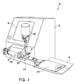
図1は、流体移送システム50の実施形態を示している。システム50は、制御装置と記憶装置とを包囲する筐体52を備え得る。システム50はユーザインターフェース54も備え得る。ユーザインターフェース54は、例えば、ディスプレイ、キーパッド、および/またはタッチスクリーンディスプレイを備え得る。ユーザインターフェース54は、例えば、移送される流体の量、および、移送される流体の種類に関して、使用者から命令を受けるように構成され得る。ユーザインターフェースは、エラーメッセージ、警告、または命令(例えば、空のバイアルを交換するために)など、使用者に情報を提供するようにも構成され得る。
FIG. 1 illustrates an embodiment of a fluid transfer system 50. The system 50 may include a housing 52 that encloses the control device and the storage device. System 50 may also include a
流体移送システム50は流体移送ステーションを備えている。一部の実施形態では、システム50は、システムが取り扱うように設計される異なる流体の種類の数、および、移送される流体の量に依存して、2つ、3つ、4つ、5つ、6つ、7つ、8つ、またはそれ以上の移送ステーションなど、複数の移送ステーションを備えることができる。各々の移送ステーションは、例えば、医療用バイアル、または、バッグ、ボトル、もしくはバットなどの他の適切な容器であり得る流体供給源容器460を備えることができる。本明細書で開示されている実施形態が、バイアルを供給源容器として使用することを詳述しているが、具体的に言及されていない場合であっても、他の容器が使用できることは理解されるものである。流体移送ステーションは、正確な量の流体を、供給源容器460から、例えばIVバッグであり得る目標容器470へと移送するように構成され得る。本明細書に記載されている様々な実施形態では、具体的に言及されていない場合であっても、異なる種類の目標容器または目的先容器がIVバッグの代わりに使用され得ることは(例えば、注射器、ボトル、バイアル、エラストマポンプなど)、理解されるものである。流体移送ステーションは、目標容器470のためのトレーなど、支持体56を備え得る。支持体56は、目標容器に移送された流体の量を決定するための重量センサなどの目的先センサを備え得る。流体は、正確な量の流体が測定できるように、供給源容器460から中間容器200へと先ず移送され得る。中間容器200は、例えば注射器であり得る。測定された後、流体は、中間容器200から目標容器470へと移送され得る。
The fluid transfer system 50 includes a fluid transfer station. In some embodiments, the system 50 is 2, 3, 4, 5 depending on the number of different fluid types that the system is designed to handle and the amount of fluid being transferred. Multiple transfer stations, such as 6, 7, 8, or more transfer stations. Each transfer station can include a
流体移送システム50は、目標容器470を分けるために、または、複数の供給源容器460から共通の目標容器470へと流体を移送および混合するために、供給源容器460から個別の流体を移送するように使用され得る。一部の実施形態では、システム50は、流体の混合物を合成するために使用され得る。例えば、システム50は、複数の薬物を一緒に混合するために、または、給餌流体(例えば、水、ブドウ糖、脂質、ビタミン、無機物)を混合するために、使用され得る。システム50は、薬物または他の流体を所望の濃度の度合いへと希釈するために使用されることもある。一部の実施形態では、単一のシステムが、流体の混合物を合成することと、単一の供給源容器から単一の目標容器へと個別の流体を移送することとの両方のために構成され得る。
Fluid transfer system 50 transfers individual fluids from
一部の実施形態では、システム50は、移送ステーションを筐体52に搭載するための搭載モジュール58を備え得る。例えば、一部の実施形態では、搭載モジュール58は、移送ステーションを筐体52へと固定するために、図1に示しているように、中間容器200を受け入れるように構成され得る。搭載モジュール58は、流体移送ステーション50のコネクタまたは他の部分と係合することもできる。システム50はモータを備えることもでき、モータは、例えば、筐体52内に収容され得る。モータは、流体を容器へと(供給源容器460から)引き込むために、および、流体を容器から(目標容器470へと)一掃するために、中間容器200を作動させるように構成され得る。モータは、供給源容器460と中間容器200と目標容器470との間のコネクタ410の流体の流れを制御するために、流れ制御機構60を作動させるように構成され得る。代替で、コネクタ410は、流れを交互に行うように手動で調節され得る。モータは、制御装置と通信していてもよく、制御装置からの作動命令を受信できる。例えば、中間容器200は、流体を注射器へと引き込むために注射器に対してプランジャを作動させるように一部の実施形態では構成されるモータで、正確な量の流体を移送するために、正確な注射器ポンプとして動作できる。モータおよび自動システム50は、手作業による注射器ポンプを使用するよりも素早くて一貫した速さで、流体の正確な移送を可能にする。例えば、大きい注射器(例えば、50mlまたは100ml)は、特には繰り返し行われる場合に手作業での実施が難しい可能性のあるプランジャの操作のために、相当の労力を必要とする可能性がある。モータおよび自動システム50は、流体移送の正確性、一貫性、および速さを向上できる。
In some embodiments, the system 50 may include a mounting module 58 for mounting the transfer station to the housing 52. For example, in some embodiments, the mounting module 58 can be configured to receive an
一部の実施形態では、システムは、流体の通過を選択的に許容するために互いに取り付けられるように構成された雄の流体コネクタと雌の流体コネクタとの1つまたは複数の対を備える。コネクタは、例えば、流体が移送されると目標容器470が取り外しできるように、取り外しまたは連結解除できる。一部の実施形態では、コネクタは、対応するコネクタから連結解除される場合に自動的に閉じ、それによって、コネクタが取り外される場合に流体が漏れるのを防止するように構成されてもよい。したがって、流体移送システム50は、流体のすべてをシステム内に実質全体的または全体的に保持する間に流体を移送するために使用でき、流体移送を、実質全体的または全体的に閉じられたシステムで行わせることができる。それによって、流体移送システム50は、流体移送システム50の構成要素を連結および連結解除する場合、液体または蒸気の漏れによって引き起こされる怪我、無駄、または損傷の危険性を低減または排除できる。
In some embodiments, the system comprises one or more pairs of male and female fluid connectors configured to be attached to each other to selectively allow passage of fluid. The connector can be removed or disconnected, for example, so that the
システム50は、注射器200を流体工学システムの他の構成要素と結合するように構成されているコネクタ300を備え得る。コネクタ300は、他の流体工学構成要素を係合解除することなく、または、他の流体工学構成要素の配向を変えることなく、注射器との流体密閉の係合を形成するように構成されている回転式ルアーコネクタであり得る。回転式コネクタ300は、搭載モジュール58内に注射器を適切に配向するために使用されてもよい。コネクタ300は、後でより詳細に説明される。
System 50 may include a
一部の実施形態では、システム50は、様々な大きさの注射器(例えば、10ml、20ml、50ml、および100ml)と適合できるように構成され得る。例えば、より大きい容積の注射器が、より大きい体積の流体を、より短い時間において移送するために、使用できる。より小さい容積の注射器は、どれだけの量の流体が移送され得るかの精度および正確性を向上させるために、使用できる。 In some embodiments, the system 50 can be configured to be compatible with various sized syringes (eg, 10 ml, 20 ml, 50 ml, and 100 ml). For example, a larger volume syringe can be used to transfer a larger volume of fluid in a shorter time. Smaller volume syringes can be used to improve the accuracy and accuracy of how much fluid can be transferred.
流体移送システム50は多くの方法で変更できる。例えば、前述したように、システム50は異なる数の移送ステーションを有することができる。また、一部の実施形態では、図1に示した特定の特徴は、移送ステーションの一部または全部について変更または省略できる。例えば、一部の実施形態では、危険でない、高価でない、または大気に敏感でない流体(例えば、生理食塩水または水)の移送に専用とされている流体移送ステーションは、危険である、高価である、または大気に敏感である流体の移送に専用とされた流体移送ステーションより、漏れ防止の特徴を少なくすることができる。 The fluid transfer system 50 can be modified in many ways. For example, as described above, the system 50 can have a different number of transfer stations. Also, in some embodiments, certain features shown in FIG. 1 can be altered or omitted for some or all of the transfer stations. For example, in some embodiments, fluid transfer stations that are dedicated to the transfer of non-hazardous, less expensive, or air-insensitive fluids (eg, saline or water) are dangerous and expensive. Or less leakage prevention features than fluid transfer stations dedicated to the transfer of fluids that are sensitive to the atmosphere.
図2〜図5は、注射器200のための流体流路インサート100の実施形態を示している。流路インサート100は、流路インサート100によって定められた流体流路に沿って流体の流れを方向転換させるように構成されている。注射器が概して水平に位置付けられる場合、注射器は、定められた流路が注射器内の上部または最も高い位置に、または、その近くに位置付けられるように配向され得る。重力は、注射器内に閉じ込められた気泡を、注射器内の上部の位置へと上昇させる。流体の流れを、注射器内の上部位置を通じて、または、上部位置の近くに流すように方向転換させることで、気泡は、流体と共に注射器から押し出され得る。
2-5 illustrate an embodiment of a fluid flow path insert 100 for the
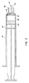
図2は、注射器200内に位置付けられた流路インサート100の実施形態を示している。注射器200は、本体202と、プランジャ204と、空洞206と、シュラウド208と、先端210とを備え得る。先端210は、注射器200の空洞206へのアクセスを提供できる、先端210を通じて軸方向に延びる導通路212を備えている。シュラウド208は、コネクタ300などのコネクタを固定するために、内面に、ルアーネジ山などの内側のネジ山を有し得る。係合は、注射器200とコネクタとの間に、ルアーロックなどの液密な連結を形成できる。一部の実施形態では、先端はネジ山を有し得る。
FIG. 2 illustrates an embodiment of the flow path insert 100 positioned within the
図3は、注射器200から取り外された流路インサート100の斜視図である。図4は流路インサート100の正面図である。図5は、線5−5に沿って切り取られた流路インサート100の断面図を示している。流路インサート100は、前面とも称される第1の面102と、後面とも称される第2の面104と、外壁106と、通路108とを有する概して円形の本体を有している。通路108は、第1の面102の中心から外壁106へと径方向に延びており、第1の面102および第2の面104を貫いて延びている。通路108は、切り欠きまたは溝としてなど、流路インサート100から材料を取り除くことで形成できる。通路108は、空洞206から導通路212まで流体導通路を定めるように構成されている。通路108は、導通路212を通じて移動する前または後に、注射器200を通じて移動する流体を、注射器200の内壁の部分へと方向転換させるように構成されている。通路108は、注射器200が流路インサート100のない場合と同じ流量を実質的に有するように、大きさおよび形が定められ得る。通路108の大きさおよび形は、なおも同じ機能性を提供する一方で、示した実施形態から相当に変わってもよい。
FIG. 3 is a perspective view of the flow path insert 100 removed from the
流路インサート100は、注射器200の空洞206内に位置付けられるような大きさおよび形とされている。流路インサート100は、流路インサートが注射器200の前壁と実質的に面一となるように、注射器200の前壁の曲率および/または角度と合致するように構成され得る。この実施形態では、インサート100の外面106が、注射器の内壁と面一となるように構成されている。この実施形態では、インサートの湾曲は、インサート100の中心から外壁106へと径方向に延びており、第1の面102および第2の面104は同じ曲率を有している。第2の面104の曲率はプランジャ204の曲率および/または角度と合致できる。一部の実施形態では、流路インサートは注射器200の前壁と実質的に面一ではない。例えば、流路インサート100の第1の面102は、流路インサートにおける1つまたは複数の突起によって、前壁からずらすことができる。流路インサート100は、外壁106と注射器200の内壁との間に液密なシールを形成し、それによって流体が注射器200の空洞206と導通路212との間で通路108だけを通って流れるように構成できる。
The flow path insert 100 is sized and shaped to be positioned within the
流路インサート100は、異なる大きさおよび種類の注射器のために構成できる。インサートは、通路インサート100と注射器200との間の液密の形成を容易にするのを助けるために、柔軟な材料または圧縮可能な材料から製作できる。一部の実施形態では、インサート100は、より硬い材料から形成できる。
The flow path insert 100 can be configured for syringes of different sizes and types. The insert can be fabricated from a flexible material or a compressible material to help facilitate the formation of a fluid tight between the
流路インサート100は、注射器の空洞206の間に流体流路を定めるように構成されている。通路108は、流体を注射器200の空洞206から先端210へと案内することができる。注射器が適切に配向される場合、通路108は、流体の流れを注射器空洞の上部に沿って案内する。空洞の上部分に沿って流体を案内することで、流体の流れは、プランジャ204が前方へと移動される場合、注射器200の空洞206内に包囲されている気泡を注射器から押し出すことができる。注射器200は、流路インサート100を注射器200内で正確に位置付けるために注射器200の配向を指示する矢印などのマークを備え得る。代替で、インサート100を設置する一部の方法は、外面106を貫く通路108を注射器200における数字と位置合わせするステップを含む。
The flow path insert 100 is configured to define a fluid flow path between the
流路インサート100は、中心に位置合わせされた流路を有する既存の注射器200を変更するために使用できる。注射器200を変更する方法は、流路インサート100を注射器200の空洞206と位置合わせするステップを含み得る。流路インサート100は、注射器200にあるマークと、流路インサートにおける通路108の位置とに従って、位置合わせされ得る。例えば、注射器は、注射器内における通路108の適切な配向を指示する数字、文字、またはマークを備え得る。流路インサート100は、機械自動化された工程など、自動化された工程を用いて、注射器内に挿入され得る。一部の実施形態では、流路インサート100は作業者によって手動で挿入され得る。
The
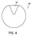
図6は、流路インサート120の別の実施形態を示している。この実施形態では、流路インサート120は楔形の通路122を有している。楔形の通路122は、注射器200内に位置付けられる流路インサート120についてより大きい領域を提供し、注射器200は、注射器200内での流路インサート120の位置付け、および/または、システム50における注射器の不正確な配置において、誤りを補償するのを助けることができる。通路122は、流体で注射器から気泡を押し出すのに十分な流体流量となるように構成され得る。
FIG. 6 illustrates another embodiment of the flow path insert 120. In this embodiment, the
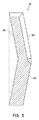
図7は、流路インサート130の別の実施形態を示している。この実施形態では、流路インサート130から径方向外向きに延びている複数の突起132がある。突起は、注射器の内壁に接し、流体を注射器200の壁に沿って強制的に案内するように構成されている。この実施形態では、流路インサート130は、注射器内においてほとんどいずれの配向で位置付けられてもよく、それでもなお、泡が生じ得る注射器200の高い位置に位置付けられる流路を提供する。
FIG. 7 illustrates another embodiment of the flow path insert 130. In this embodiment, there are a plurality of
図3〜図7は流路インサートのいくつかの実施形態を示しており、多くの異なる変形が存在し、検討される。一部の実施形態では、通路の形は、図6に示しているようなものなど、変更できる。一部の実施形態では、流路インサートの形は、図7に示している実施形態など、変更できる。図2〜図7に示した実施形態では、流路インサートは概して円形である。一部の実施形態では、流路インサートは円形ではない。例えば、流路インサートは、丸められた外壁ではなく、長円形、すなわち、切り取られた平らな部分を伴う円であり得る。流路インサートおよび通路は、注射器の中心から外壁へと流体の流れを方向転換させるために、様々な方法で形作られ得る。 3-7 illustrate several embodiments of flow path inserts, many different variations exist and are contemplated. In some embodiments, the shape of the passageway can be changed, such as that shown in FIG. In some embodiments, the shape of the channel insert can be varied, such as the embodiment shown in FIG. In the embodiment shown in FIGS. 2-7, the flow path insert is generally circular. In some embodiments, the flow path insert is not circular. For example, the channel insert may be an oval, i.e. a circle with a cut flat part, rather than a rounded outer wall. The flow path inserts and passages can be shaped in various ways to redirect fluid flow from the center of the syringe to the outer wall.
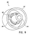
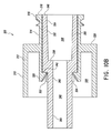
図8〜図11はコネクタ300の実施形態を示している。図8はコネクタ300の斜視図を示している。図9はコネクタ300の異なる斜視図を示している。図10Aはコネクタ300の斜視断面図を示している。図10Bはコネクタ300の同じ断面の異なる斜視図を示している。図11はコネクタ300の分解図を示している。
8 to 11 show an embodiment of the
コネクタ300は外側筐体310と内側筐体330とを備え得る。外側筐体310は、概して形が管状であり、筐体310を通じて軸方向に延びる導通路を有している。外側筐体310は、基礎部312とも称されるより大きい直径部と、注射器係合部314とも称されるより小さい直径部とを備えている。注射器係合部314は外ネジ山316と外面318とを有している。より大きい直径部は空洞326を有している。多数を含む1つまたは複数の保持クリップ320と、多数を含む1つまたは複数の突起324とが、内側筐体330のための空洞の周りに位置付けられている。1つまたは複数の保持クリップ320は、軸方向内向きに延びるクリップ部322を有している。1つまたは複数の突起324は長手方向に延びている。内側筐体330は外側筐体310内に位置付けられるように構成される。
The
内側筐体330は、先端係合部とも称される管部332と、コネクタ部340とを有している。管部332はコネクタ部340より大きい直径を有している。内側筐体330は、外面342と、内面336と、コネクタ部340の遠端から内面336へと軸方向に延びる導通路346とを有している。管部332は、面348において開口しているより大きい直径から、内面336において開口しているより小さい直径まで先細りである先細り内壁334を有している。
The
内側筐体は、内側筐体330が外側筐体310内で回転できるように外側筐体310内に位置決めされている。内側筐体の外面342は、保持クリップ320に隣接して位置付けられている。外側筐体310および内側筐体330は、内側筐体330が外側筐体310内に位置付けられる場合、内側筐体の面348と外側筐体の面318とが実質的に同一平面となるように構成され得る。内側筐体330は動かないままであるように構成されており、外側筐体310は内側筐体330の周りに回転するように構成されている。空洞338が、注射器の先端210を受け入れ、内面336と注射器の先端210との間にシールを形成するように構成されてもよく、これは、注射器200と内側筐体330との間に流体密閉の連結を作り出すことができる。
The inner housing is positioned within the
一部の実施形態では、内側筐体330のコネクタ部340は、図12に示しているような流体工学システムの止め栓などのコネクタに結合されるように構成されている。外側筐体310は注射器と係合するように構成されている。例えば、ネジ山316は、注射器200のシュラウド208の内壁におけるネジ山と係合でき、これは、注射器200の先端210を内側筐体330の空洞338内に位置付ける。内側筐体330は動かないままであり、外側筐体310は内側筐体330の周りに回転するように構成されている。外側筐体310が回転して注射器200と係合するにつれて、保持クリップ320は、シールが注射器と内側筐体330との間に形成され得るように、外側筐体310内における内側筐体330の位置を維持する。保持クリップ320は、好ましくは、外側筐体310を内側筐体330の周りに回転させることができる一方で、それら筐体の相対的な長手方向の位置を維持する。
In some embodiments, the
保持クリップ320によって、内側筐体330のコネクタ部340がコネクタ410などの別のコネクタに固定された後、コネクタ300を組み立てることができるようになる。外側筐体310は、外側筐体310を内側筐体330の管部332へと押すことによって、内側筐体330に位置決めされ得る。保持クリップ320は、外側筐体310が所定位置へと移動されていくにつれて管部332のより大きい直径を受け入れるように、外向きに押され得る。外側筐体310が内側筐体330に適切に位置付けられる場合、保持クリップは、図10Bに示しているように、内側筐体330の外面342に接する位置へと移動できる。
After the
代替の実施形態(図示せず)では、保持クリップ320と長手方向の突起324とは、クリップ部322などの軸方向内向きに延びる保持部で置き換えられてもよい。保持部は、一定の直径を持つオリフィスを形成し、内側筐体330の外面342に接するように構成される連続面を有し得る。このような実施形態では、コネクタ300は、内側筐体330を別のコネクタに結合する前に組み立てられる。
In an alternative embodiment (not shown), the retaining
コネクタ300は、ポリカーボネートまたは他のポリマー材料など、様々な材料から構築できる。コネクタ300は、剛体のプラスチック材料または他の剛体のポリマー材料から構築できる。一部の実施形態では、内側筐体は、外側筐体と異なる材料から構築されてもよい。例えば、外側筐体は剛体の材料から構築され得、内側筐体はより柔軟な材料から形成できる。柔軟な材料は、注射器と内側筐体330との間にシールを形成するのを助けることができる。
The
図12は、注射器200とコネクタ300とを連結するための工程を示している。コネクタ300の注射器接合部314は、注射器200のシュラウド208の内ネジ山と係合するように構成されている。コネクタの外側筐体310は、シュラウドと係合するために回転するように構成されており、一方、注射器200の先端210は、内側筐体330内に位置付けられる。外側筐体310が内側筐体330の周りに回転するにつれて、先端210は、内側筐体330の空洞338内に位置決めされる。コネクタ300は、注射器接合部が注射器と係合される場合、注射器200と内側筐体330との間に流体密閉の連結を形成するように構成されている。コネクタ300の外側筐体310を操作することで、注射器は、流路が正確な配向で(例えば、流路が注射器200の最も上方の部分に位置付けられている状態で)位置付けられる所望の配向を維持しつつ、コネクタ300と係合され得る。一部の実施形態では、注射器200は、注射器200の正確な配向を指示するマークを注射器の外側に有してもよい。
FIG. 12 shows a process for connecting the
一部の実施形態では、注射器接合部314は、係合される場合にコネクタ300に対する注射器200の位置を制御するように構成される内側筐体330の面336などの停止機構を備えてもよい。注射器200がコネクタ300の注射器接合部314と係合する場合、コネクタ300は、注射器200が所望の位置へと係合されると注射器200の先端210がコネクタ300の内面336に接するように、構成され得る。内面336は、先端210が所望の係合位置を越えて過度に挿入されるのを防止できる。他の停止機構が使用されてもよい。例えば、コネクタ300は、注射器200が所望の係合位置に到達した場合に注射器200のシュラウド208が接するように注射器接合部314に形成された環状部328を備えてもよい。
In some embodiments, the syringe joint 314 may comprise a stop mechanism, such as the
停止機構(例えば、面336)は、流体の正確な移送を容易にすることができる。例えば、注射器200が所望の位置を越えて過度に挿入された場合、プランジャが後へと引かれる場合に過剰な流体の量が注射器200へと引き込まれ、それにより、特には複数回の注射器の充填を必要とする体積を伴う流体移送について、流体移送の精度を妥協する可能性がある。また、流体工学システムの内部容積は、注射器が過度に挿入される場合、予期されている内部容量より少量だけ小さくなり得るため、流体工学的な呼び水が、早い段階でIVバッグへと流体を押し込む結果をもたらす可能性がある。
A stop mechanism (eg, surface 336) can facilitate accurate transfer of fluid. For example, if the
図13Aは、図1に示した実施形態などの流体移送ステーションと共に使用できる流体工学アセンブリ400の斜視図である。図13Bは、バイアル460などの供給源容器と、図13Aのアセンブリ400に結合されたIVバッグアセンブリ470などの目標容器とを伴う流体工学アセンブリ400の図である。流体工学アセンブリ400は、注射器200などの中間容器を介して供給源容器から目標容器へと正確な量の流体を移送するために使用され得る。流体工学アセンブリ400は、バイアル460と、バイアル460内に収容された流体(例えば、化学療法薬または他の薬物)との流体連通を提供するように構成されたバイアルアダプタ450と、注射器200と、IVバッグアセンブリ470と、流体をバイアルアダプタ450から注射器200へと、および、注射器200からIVバッグアセンブリ470に向かって案内するためのコネクタ410とを備えている。一部の実施形態では、流体工学アセンブリ400は、コネクタ410または注射器200を交換することなく、(例えば、バイアルに流体がなくなった場合)バイアル460および/またはバイアルアダプタ450を交換することができるように構成され得る。一部の実施形態では、バイアルアダプタ450は、それを介してバイアル460に空気を入れ、それによって、流体が引き込まれるにつれてバイアル460における圧力を実質的に等しくするように構成され得る。
FIG. 13A is a perspective view of a
バイアルアダプタ450の上方部は、バイアル460の蓋における隔膜を穿孔するように構成された、図13Aに示しているような棘部と、バイアル460をバイアルアダプタ450において保持するように構成された腕部とを備え得る。上方部の反対において、バイアルアダプタは、例えば雌コネクタ440であり得るコネクタ440を備え得る。コネクタ440は、例えば、San Clemente, CaliforniaのICU Medical, Inc.,によって製造されているClave(登録商標)コネクタの型式であり得る。この種類のコネクタの様々な実施形態が’866特許に記載されている。雌コネクタ440は、雄コネクタが雌コネクタ440に取り付けられるまで、流体がバイアルアダプタ450から漏れないように、バイアルアダプタ450の端を封止できる。本明細書で詳述されている多くの実施形態では、雄コネクタと雌コネクタとが入れ替えられ得ることは、理解されるべきである。例えば、バイアルアダプタ450は、コネクタ410における雌コネクタと合致するように構成された雄コネクタを備えてもよい。
The upper portion of the vial adapter 450 includes a barb as shown in FIG. 13A configured to pierce the septum in the lid of the
バイアルアダプタ450は、バイアル460から除去された流体を補償して圧力差を低減するために、空気をバイアル460へと案内するように構成された空気吸入路を備え得る。空気吸入路は、バイアル460に向けて空気を通過させる一方で流体が通過するのを防止するように構成されたフィルタを備えることができる。例えば、フィルタは、空気浸透性であるが流体不浸透性の膜を備えることができる。フィルタは疎水性フィルタであり得る。一部の実施形態では、バイアルアダプタ450は、フィルタに代わって、または、フィルタに加えて、逆止弁を備え得る。逆止弁は、ダックビル弁、スリット弁、滑りボール弁、または任意の他の適切な種類の逆止弁とすることができる。バイアルアダプタ450は、’157公開に記載されている実施形態と同様に、投入空気がバイアル460の内部の流体と接触するのを防止する一方で容積が増加するように構成されるバッグを有してもよい。
The vial adapter 450 may include an air suction path configured to guide air into the
IVバッグアセンブリ470は、IVバッグ472と、ある長さの管476と、雌コネクタ474とを備え得る。雌コネクタ474は、管476に取り外し可能または取り外し不可能に取り付けられ得る。雌コネクタ474は、雄コネクタがコネクタ474に取り付けられる場合を除いて、流体がIVバッグ472から漏れないようにIVバッグアセンブリ470を封止するように構成され得る。一部の実施形態では、IVバッグアセンブリ470は、IVバッグ472へのアクセスも提供するために、補足的な配管478を備え得る。補足配管478は、第2の流体(主配管476を通じて移送される流体と異なる可能性がある)をIVバッグ472へと移送するために使用されてもよい。例えば、管476は、濃縮された液体(例えば、薬物)をIVバッグ472へと移送するために使用でき、補足管478は、濃縮された流体を所望の度合いの濃度へと希釈するために希釈液(例えば、生理食塩水または水)をIVバッグ472へと移送するために使用できる。一部の実施形態では、補足的な配管478は、流体配管を補足配管478に取り外し可能に取り付けることができるように、コネクタ474と同様であり得る蓋またはコネクタ(図示せず)を有し得る。一部の実施形態では、複数の流体が(例えば、異なる流体移送ステーションから)IVバッグ472へと単一の流体配管(例えば、管476)を通じて案内され得るように、複数の流体配管が(例えば、Y字またはT字の連結において)組み合わされてもよい。一部の実施形態では、コネクタ474はバッグ472と、それらの間に相当の長さの管476を用いることなく、直接的に結合されてもよい。
The
コネクタ410は、止め栓など、複数の流体路に沿って流体を案内することができるコネクタであり得る。一部の実施形態では、コネクタ410は、コネクタ410におけるレバー412によってなど、手動で操作できる。一部の実施形態では、コネクタ410は、流体移送ステーション50と併用してなど、システムの一部として自動的に制御され得る。例えば、流体移送ステーション50は、複数の流体通路の間で切り替わるために、弁、スイッチ、レバーなどを制御する機構60を有することができる。第1の雄コネクタ420はコネクタ410の雌端部414に取り付けられ得る。第2の雄コネクタ430はコネクタ410の雌端部416に取り付けられ得る。
The
雄コネクタ420、430は、対応する雌コネクタと係合されていない場合、流体がコネクタから漏れる、または、流体がコネクタへと入るのを防止するが、対応する雌コネクタ440、474と係合される場合、流体が流れるのを許容するように構成されている閉止可能な雄のルアーコネクタであり得る。図示した実施形態では、コネクタ420、430は、San Clemente, CaliforniaのICU Medical, Inc.,によって製造されているSpiros(登録商標)の閉止可能な雄コネクタの型式であり得る。一部の実施形態では、対応する自動的に閉止可能な雄および雌コネクタを、流体移送システム50内の様々な(または、すべての)連結位置に設け、それによって、動かない流体を、連結解除において流体供給源、流体モジュール、および流体目標のそれぞれの内部に全体として実質的に留めさせることと、概してシステムの外部への漏洩または蒸発をさせないこととによって、少なくとも一部において、実質全体的または全体的に閉じられたシステムが達成できる。例えば、一部の実施形態では、自動的に閉じるコネクタ(例えば、雄および雌コネクタ)の対応する対は、流体供給源とコネクタ410との間の接合部、および/または、コネクタ410と目標容器との間の接合部に、設けられ得る。この種類のコネクタの様々な実施形態が’920公開に記載されている。
The
この実施形態、および、本明細書に記載されている他の実施形態では、システムは、雄コネクタまたは雌コネクタを備えるとして記載されており、雌コネクタが、記載された雄コネクタの代わりに使用されることと、雄コネクタが、記載された雌コネクタの代わりに使用されることとが、可能であり得る。例えば、コネクタ420および430の一方または両方は、雌コネクタ(例えば、San Clemente, CaliforniaのICU Medical, Inc.,によって製造されているClave(登録商標)コネクタ)とすることができ、バイアルアダプタ450のコネクタ440およびIVバッグ472のコネクタ474は、雄コネクタ(例えば、San Clemente, CaliforniaのICU Medical, Inc.,によって製造されているSpiros(登録商標)の閉止可能な雄コネクタ)とすることができる。
In this embodiment, and in other embodiments described herein, the system is described as comprising a male connector or a female connector, and a female connector is used in place of the described male connector. And that a male connector can be used in place of the described female connector. For example, one or both of
コネクタ300はコネクタ410の雌端部418に取り付けられ得る。コネクタの内側筐体330は、回転できないように、コネクタの雌端部418に固定または固着される。内側筐体330は、音波溶接、スナップ留め構造(図示せず)、圧力もしくは摩擦の嵌め込み、または他の適切な連結の種類によって、コネクタ410の雌端部418に固定され得る。外側筐体310は内側筐体330の周りに自由に回転できる。コネクタ300は、外側筐体310を内側筐体330の周りに回転させることで、注射器200と係合できる。外側筐体310は、流体工学アセンブリ400から独立して回転できる。それによって、コネクタ300の外側筐体310は、移動すること、回転すること、操作すること、または、内側筐体330に連結されている流体工学アセンブリ400の配向に影響を与えることなく、注射器200に係合できる。
一部の実施形態では、コネクタ410は、図1に示しているものなど、コネクタを流体移送ステーションに固定するように構成されている機械的な構成および特徴を有し得る。多くの変形が可能である。
In some embodiments, the
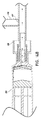
図14Aは注射器200の断面図であり、コネクタ300およびコネクタ410は、コネクタ410およびコネクタ300を通じてバイアル460から注射器200へと流れる流体を示している。注射器200のプランジャが引き抜かれるにつれて、流体は、注射器のインサート100によって定められる流路に沿って、注射器200へと引き込まれる。この実施形態では、コネクタ410は、流体がバイアル460から注射器200へと流れるのを許容されるように位置付けられる弁411を有するコネクタである。一部の実施形態では、弁411は、レバー412の手動の操作によって位置付けられ得る。一部の実施形態では、弁411は、弁411の作動を制御するように構成された自動機構によって位置付けられ得る。弁411が図示した位置にある状態で、注射器200へと引き込まれる流体は、バイアル460から引き込まれるが、IVバッグ472からは引き込まれない。流体がバイアル460から引き込まれるにつれて、前述したように、空気が空気吸入路を通じてバイアル460に入ることができる。
14A is a cross-sectional view of
図14Bは注射器200の断面図であり、コネクタ300およびコネクタ410は、コネクタ300およびコネクタ410を通じて注射器200からIVバッグアセンブリ370に向かって流れる流体を示している。この例では、弁411は、注射器200のプランジャが前進されるにつれて流体が注射器200から駆り出されるように、位置付けられる。流体は、注射器200からIVバッグアセンブリ470に向かって流れるように許容される。気泡は、注射器内に集まる可能性があり、注射器200の最も高い部分へと上昇する。図示した実施形態では、注射器は実質的に水平に位置付けられる。概して、流路インサート100のない場合、流体は注射器の中心軸に沿って流路から流れ出し、気泡は概して注射器200内に留まることになる。流路インサート100は、流体を注射器200の上部または上部の近くから強制的に流し出すために、流体の流れを方向転換させるように構成されており、それによって、気泡を、流体と共に、流路インサート100によって定められた流路に沿って注射器200から押し出す。注射器200は、コネクタ300の外側筐体310を操作することによって、流路が正しい配向(例えば、流路が注射器200の最も上方の部分に位置付けられる)で位置付けられるように、配向され得る。一部の実施形態では、注射器200は、注射器200の正確な配向を指示するマークを注射器の外側に有してもよい。弁が図示した位置にある状態で、注射器200から駆り出される流体および気泡は、IVバッグ470へと案内され、バイアル460へと案内されない。
FIG. 14B is a cross-sectional view of
以下の列記は、本開示の範囲内にある例示の実施形態を有している。列記されている例示の実施形態は、実施形態の範囲を限定するとして決して解釈されるべきではない。列記されている例示の実施形態の様々な特徴は、本開示の一部である追加の実施形態を形成するために、除外、追加、または組み合わされてもよい。
1.流体を収容するように構成される空洞を定める管状本体壁と、
空洞内に少なくとも部分的に位置付けられ、空洞内で注射器の中心軸に沿って軸方向に移動するように構成されるプランジャであって、プランジャの移動が空洞の容積を変える、プランジャと、
注射器本体から軸方向に延び、注射器の中心軸に中心付けられる先端であって、導通路が先端を通じて軸方向に延びる、先端と、
導通路と空洞との間に位置付けられる流路インサートであって、流路インサートが、空洞と導通路との間の流体通路を定め、流体通路が、導通路から管状本体壁まで延びる、流路インサートと
を備える注射器。
2.流体通路は、流路インサートの面における、流路インサートの中心から管状本体壁へと径方向に延びる溝である、実施形態1の注射器。
3.流路インサートは、導通路と空洞との間に、導通路と空洞との間での流体通路への流体の流れを制限する流体密閉シールを形成する、実施形態2の注射器。
4.流体通路は、流路インサートに形成される楔形の溝である、実施形態1の注射器。
5.流体通路は、管状本体壁と流路インサートとの間に隙間を形成する、実施形態1の注射器。
6.流路インサートは、空洞と導通路との間に複数の流体通路を定める、実施形態1の注射器。
7.流路インサートは円形である、実施形態1の注射器。
8.流路インサートは長円形である、実施形態1の注射器。
9.注射器は、注射器本体の外部に、注射器の所望の配向を指示する印を備える、実施形態1の注射器。
10.基礎部および注射器係合部を備える外側筐体であって、第1の導通路が外側筐体を通じて延び、注射器係合部は、注射器における合致するネジ山と係合するように構成される複数のネジ山を有し、基礎部は1つまたは複数の保持要素を有する、外側筐体と、
コネクタ部および管部を備え、外側筐体の第1の導通路内に位置付けられる内側筐体であって、第2の導通路は内側筐体を通って軸方向に延び、管部は、第2の導通路内で注射器の先端を受け入れるように構成される、内側筐体と
を備え、
1つまたは複数の保持要素は、内側筐体を第1の導通路内に位置付けるように構成され、外側筐体は、注射器における合致するネジ山と係合するために、内側筐体の周りに回転するように構成される、装置。
11.管部は、第2の導通路内に配置される内面をさらに備え、内面は、注射器の先端と内側筐体との間に流体シールを形成するように構成される、実施形態10の装置。
12.管部は、注射器の先端を受け入れるように構成される先細りの壁を備える、実施形態10の装置。
13.複数の保持要素は、第1の導通路へと軸方向に延び、内側筐体の外面に接する保持クリップである、実施形態10の装置。
14.コネクタ部は、内側筐体の位置が固定されるように、流体工学システムに結合される、実施形態10の装置。
15.第2の導通路は流体工学システムと流体連通している、実施形態14の装置。
16.注射器係合部は、外側筐体に対する注射器の位置を制御するように構成される環状部をさらに備える、実施形態10の装置。
17.注射器をコネクタの外側筐体に対して配向するステップであって、コネクタの位置は固定され、注射器の先端は、コネクタの軸方向導通路と位置合わせされる、ステップと、
コネクタの外側筐体をコネクタの固定された内側筐体の周りに回転させることで、コネクタの外側筐体を注射器と結合するステップであって、外側筐体は、注射器における合致するネジ山と係合するように構成される複数の外ネジ山を備える、ステップと、
先端が内側筐体の軸方向導通路と係合されるまで外側筐体を回転させることによって、内側筐体と注射器の先端との間にシールを形成するステップであって、注射器の導通路が内側筐体の導通路と流体連通している、ステップと
を含む方法。
18.内側筐体は流体工学システムに固定される、実施形態17の方法。
19.注射器は、流体工学システムの配向を操作することなく、コネクタに結合される、実施形態18の方法。
20.注射器を配向するステップは、注射器における印に基づいて注射器を配向するステップを含む、実施形態17の方法。
The following list has exemplary embodiments that are within the scope of the present disclosure. The listed exemplary embodiments should in no way be construed as limiting the scope of the embodiments. Various features of the listed exemplary embodiments may be excluded, added, or combined to form additional embodiments that are part of this disclosure.
1. A tubular body wall defining a cavity configured to contain a fluid;
A plunger positioned at least partially within the cavity and configured to move axially along the central axis of the syringe within the cavity, wherein movement of the plunger changes the volume of the cavity;
A tip extending axially from the syringe body and centered on a central axis of the syringe, the tip having a conduction path extending axially through the tip;
A flow path insert positioned between a conduction path and a cavity, the flow path insert defining a fluid path between the cavity and the conduction path, wherein the fluid path extends from the conduction path to the tubular body wall A syringe comprising an insert.
2. The syringe of embodiment 1, wherein the fluid passage is a groove in the face of the flow path insert that extends radially from the center of the flow path insert to the tubular body wall.
3. The syringe of embodiment 2, wherein the flow path insert forms a fluid tight seal between the conduit and the cavity that restricts fluid flow to the fluid passage between the conduit and the cavity.
4). The syringe of embodiment 1, wherein the fluid passage is a wedge-shaped groove formed in the flow path insert.
5. The syringe of embodiment 1, wherein the fluid passage forms a gap between the tubular body wall and the flow path insert.
6). The syringe of embodiment 1, wherein the flow path insert defines a plurality of fluid passages between the cavity and the conducting path.
7). The syringe of embodiment 1, wherein the flow path insert is circular.
8). The syringe of embodiment 1, wherein the flow path insert is oval.
9. The syringe of embodiment 1, wherein the syringe comprises a mark on the exterior of the syringe body that indicates the desired orientation of the syringe.
10. A plurality of outer housings comprising a base and a syringe engaging portion, wherein the first conducting path extends through the outer housing and the syringe engaging portion is configured to engage a matching thread in the syringe. An outer housing having a thread and a foundation having one or more retaining elements;
An inner housing having a connector portion and a tube portion and positioned in the first conduction path of the outer housing, wherein the second conduction path extends in the axial direction through the inner housing; An inner housing configured to receive the tip of the syringe in the two conduction paths;
One or more retaining elements are configured to position the inner housing within the first conduit and the outer housing is disposed about the inner housing to engage a matching thread in the syringe. A device that is configured to rotate.
11. The apparatus of embodiment 10, wherein the tube further comprises an inner surface disposed within the second conduit, the inner surface configured to form a fluid seal between the tip of the syringe and the inner housing.
12 The apparatus of embodiment 10, wherein the tube comprises a tapered wall configured to receive a tip of a syringe.
13. The apparatus of embodiment 10, wherein the plurality of retaining elements are retaining clips that extend axially into the first conducting path and contact the outer surface of the inner housing.
14 The apparatus of embodiment 10, wherein the connector portion is coupled to the fluidics system such that the position of the inner housing is fixed.
15. The apparatus of embodiment 14, wherein the second conduit is in fluid communication with the fluidics system.
16. The apparatus of embodiment 10, wherein the syringe engagement portion further comprises an annulus configured to control the position of the syringe relative to the outer housing.
17. Orienting the syringe relative to the outer housing of the connector, wherein the position of the connector is fixed and the tip of the syringe is aligned with the axial passage of the connector;
Rotating the outer housing of the connector around the fixed inner housing of the connector to couple the outer housing of the connector with the syringe, the outer housing being associated with a matching thread in the syringe. Comprising a plurality of external threads configured to mate, and
Forming a seal between the inner housing and the tip of the syringe by rotating the outer housing until the tip engages with the axial passage of the inner housing, A step in fluid communication with a conduction path of the inner housing.
18. Embodiment 18. The method of embodiment 17, wherein the inner housing is secured to the fluidics system.
19. The method of embodiment 18, wherein the syringe is coupled to the connector without manipulating the orientation of the fluidics system.
20. The method of embodiment 17, wherein orienting the syringe comprises orienting the syringe based on the indicia on the syringe.
実施形態は、添付の図面との関連で記載されてきた。しかしながら、前述の実施形態が、本明細書で記載したデバイス、システムなどを当業者が製作して使用することができるように、詳細な度合いで記載されていることは、理解されるべきである。幅広い様々な変形が可能である。構成要素、要素、および/またはステップは、変更、追加、除去、または再配置され得る。また、処理ステップが、追加、除去、または順序変更されてもよい。特定の実施形態が明示的に記載されてきたが、他の実施形態も、この開示に基づいて、当業者には明らかなものである。 Embodiments have been described in connection with the accompanying drawings. However, it should be understood that the foregoing embodiments are described in sufficient detail to enable those skilled in the art to make and use the devices, systems, etc. described herein. . A wide variety of variations are possible. Components, elements, and / or steps may be changed, added, removed, or rearranged. Also, processing steps may be added, removed, or reordered. While specific embodiments have been explicitly described, other embodiments will be apparent to those skilled in the art based on this disclosure.
本明細書に記載されているシステムおよび方法の一部の態様は、例えば、コンピュータソフトウェア、ハードウェア、ファームウェア、または、ソフトウェア、ハードウェア、およびファームウェアの組み合わせを用いて、有利に実施され得る。ソフトウェアは、本明細書に記載されている機能を実施するためのコンピュータ実行可能なコードを含み得る。一部の実施形態では、コンピュータ実行可能なコードは、1つまたは複数の汎用コンピュータによって実行される。しかしながら、当業者は、汎用コンピュータにおいて実行されるソフトウェアを用いて実施され得る任意のモジュールが、ソフトウェア、ハードウェア、またはファームウェアの異なる組み合わせを用いて実施されてもよいことを、この開示を考慮して理解するものである。例えば、このようなモジュールは、集積回路の組み合わせを用いるハードウェアで完全に実施され得る。代替または追加で、このようなモジュールは、汎用コンピュータによってではなく、本明細書において記載されている特定の機能を実施するように設計された特化したコンピュータを全体的または部分的に用いて実施される。 Some aspects of the systems and methods described herein may be advantageously implemented using, for example, computer software, hardware, firmware, or a combination of software, hardware, and firmware. The software may include computer-executable code for performing the functions described herein. In some embodiments, the computer-executable code is executed by one or more general purpose computers. However, those skilled in the art will consider this disclosure that any module that can be implemented using software running on a general purpose computer may be implemented using different combinations of software, hardware, or firmware. To understand. For example, such a module may be fully implemented in hardware using a combination of integrated circuits. Alternatively or additionally, such modules may be implemented in whole or in part using specialized computers designed to perform the specific functions described herein, rather than by general purpose computers. Is done.
特定の実施形態が明示的に記載されてきたが、他の実施形態が、この開示に基づいて、当業者には明らかになるものである。そのため、本発明の範囲は、1つもしくは複数の公報において最終的に公開されるような請求項、または、1つもしくは複数の特許において発行されるような請求項への参照によって、明示的に記載されている実施形態に関してだけではなく定められるように意図されている。 While specific embodiments have been explicitly described, other embodiments will become apparent to those skilled in the art based on this disclosure. As such, the scope of the present invention is explicitly set forth by reference to the claims as ultimately published in one or more publications or the claims as issued in one or more patents. It is intended to be defined not only with respect to the described embodiments.
50 流体移送システム、流体移送ステーション、モータおよび自動システム
52 筐体
54 ユーザインターフェース
56 支持体
58 搭載モジュール
60 流れ制御機構
100 流路インサート
102 第1の面
104 第2の面
106 外壁、外面
108 通路
120 流路インサート
122 楔形の通路
130 流路インサート
132 突起
200 中間容器、注射器
202 本体
204 プランジャ
206 空洞
208 シュラウド
210 先端
212 導通路
300 コネクタ
310 外側筐体
312 基礎部
314 注射器係合部、注射器接合部
316 外ネジ山
318 外面
320 保持クリップ
322 クリップ部
324 突起
326 空洞
328 環状部
330 内側筐体
332 管部
334 先細り内壁
336 内面
338 空洞
340 コネクタ部
342 外面
346 導通路
348 面
370 IVバッグアセンブリ
400 流体工学アセンブリ
410 コネクタ
411 弁
414 雌端部
416 雌端部
418 雌端部
420 第1の雄コネクタ
430 第2の雄コネクタ
440 コネクタ
450 バイアルアダプタ
460 供給源容器、バイアル
470 目標容器、IVバッグアセンブリ
472 IVバッグ
474 コネクタ
476 主配管
478 補足配管
DESCRIPTION OF SYMBOLS 50 Fluid transfer system, fluid transfer station, motor and automatic system 52
Claims (20)
雄または雌の流体コネクタを備え、流体供給源容器と流体連通して取り付け可能であるように構成された第1の流体コネクタと、
雄または雌の流体コネクタを備え、流体目標容器と流体連通して取り付け可能であるように構成された第2の流体コネクタと、
中間容器と、
複数の流体通路の間で切り替わるように構成された弁を有するコネクタであって、前記複数の流体通路は、前記流体供給源容器から前記中間容器へと流れるように構成された第1の流体通路、および前記中間容器から前記流体目標容器へと流れるように構成された第2の流体通路を含む、コネクタと
を備え、
前記コネクタが前記自動システムに固定されるように構成され、前記弁が、医療用流体を移送するための前記自動システムの自動機構によって、前記複数の流体通路の間に位置付けられるように構成されている、流体工学アセンブリ。 A fluidics assembly configured for use with an automated system for transporting medical fluids, comprising:
A first fluid connector comprising a male or female fluid connector and configured to be attachable in fluid communication with a fluid source container;
A second fluid connector comprising a male or female fluid connector and configured to be attachable in fluid communication with the fluid target container;
An intermediate container;
A connector having a valve configured to switch between a plurality of fluid passages, wherein the plurality of fluid passages are configured to flow from the fluid source container to the intermediate container. And a connector including a second fluid passage configured to flow from the intermediate container to the fluid target container, and
The connector is configured to be secured to the automated system, and the valve is configured to be positioned between the plurality of fluid passages by an automated mechanism of the automated system for transferring medical fluid. Is a fluid engineering assembly.
前記流体移送ステーションに固定されるように構成され、複数の雄または雌コネクタ、注射器、および、弁を有するコネクタを備える流体工学アセンブリと
を備える医療流体システムであって、
前記流体移送ステーションは、前記弁を有する前記コネクタを、供給源容器から注射器への通路と、前記注射器から目的先容器に向かう通路との間で切り替えるように自動的に制御するように構成されている、医療用流体移送システム。 A fluid transfer station comprising a display and a keypad;
A fluidics assembly configured to be secured to the fluid transfer station and comprising a plurality of male or female connectors, a syringe, and a connector having a valve, comprising:
The fluid transfer station is configured to automatically control the connector having the valve to switch between a path from a source container to a syringe and a path from the syringe to a destination container. A medical fluid transfer system.
ディスプレイおよびキーパッドを伴う流体移送ステーションを提供するステップと、
前記流体移送ステーションに固定されるように構成され、弁を備えるコネクタに取り付けられる第1および第2の雄または雌コネクタを備える流体工学アセンブリを提供するステップと
を含み、
前記流体移送ステーションは、前記弁を有する前記コネクタを、複数の通路の間で切り替えるように自動的に制御するように構成されている、方法。 A method for enabling the transfer of medical fluid comprising:
Providing a fluid transfer station with a display and a keypad;
Providing a fluidics assembly comprising first and second male or female connectors configured to be secured to the fluid transfer station and attached to a connector comprising a valve;
The fluid transfer station is configured to automatically control the connector having the valve to switch between a plurality of passages.
Applications Claiming Priority (3)
| Application Number | Priority Date | Filing Date | Title |
|---|---|---|---|
| US201462024247P | 2014-07-14 | 2014-07-14 | |
| US62/024,247 | 2014-07-14 | ||
| PCT/US2015/040174 WO2016010909A2 (en) | 2014-07-14 | 2015-07-13 | Fluid transfer devices and methods of use |
Publications (2)
| Publication Number | Publication Date |
|---|---|
| JP2017524456A true JP2017524456A (en) | 2017-08-31 |
| JP2017524456A5 JP2017524456A5 (en) | 2018-08-23 |
Family
ID=55079154
Family Applications (1)
| Application Number | Title | Priority Date | Filing Date |
|---|---|---|---|
| JP2017502131A Pending JP2017524456A (en) | 2014-07-14 | 2015-07-13 | Fluid transfer device and method of use |
Country Status (6)
| Country | Link |
|---|---|
| US (1) | US20170129763A1 (en) |
| EP (1) | EP3169925A4 (en) |
| JP (1) | JP2017524456A (en) |
| AU (1) | AU2015289952A1 (en) |
| CA (1) | CA2951967A1 (en) |
| WO (1) | WO2016010909A2 (en) |
Families Citing this family (13)
| Publication number | Priority date | Publication date | Assignee | Title |
|---|---|---|---|---|
| WO2011014525A2 (en) | 2009-07-29 | 2011-02-03 | Icu Medical, Inc. | Fluid transfer devices and methods of use |
| KR102481494B1 (en) | 2011-12-22 | 2022-12-26 | 아이씨유 메디칼 인코퍼레이티드 | A medical fluid transfer system, a fluid transfer method, an electronic medical fluid transfer system, and a method of using an electronic medical fluid transfer system |
| AU2014353184B2 (en) | 2013-11-25 | 2017-08-17 | Icu Medical, Inc. | Methods and system for filling IV bags with therapeutic fluid |
| WO2017096072A1 (en) | 2015-12-04 | 2017-06-08 | Icu Medical, Inc. | Systems methods and components for transferring medical fluids |
| USD851745S1 (en) | 2016-07-19 | 2019-06-18 | Icu Medical, Inc. | Medical fluid transfer system |
| WO2018022640A1 (en) | 2016-07-25 | 2018-02-01 | Icu Medical, Inc. | Systems, methods, and components for trapping air bubbles in medical fluid transfer modules and systems |
| US10926025B2 (en) * | 2016-09-15 | 2021-02-23 | Tandem Diabetes Care, Inc. | Vial supporter for medicament pump |
| US11324664B2 (en) * | 2017-03-24 | 2022-05-10 | Carefusion 303, Inc. | Dry disconnect cartridge and dual lumen needle for automatic drug compounder |
| EP3431121A1 (en) * | 2017-07-20 | 2019-01-23 | Epsilon Elektronik Sanayi ve Ticaret A.S. | A medical fluid transfer system and method of use |
| EP3659573B1 (en) * | 2017-07-25 | 2023-10-04 | JMS Co., Ltd. | Liquid medicine preparation apparatus |
| CA3136125A1 (en) | 2019-04-17 | 2020-10-22 | Icu Medical, Inc. | System for onboard electronic encoding of the contents and administration parameters of iv containers and the secure use and disposal thereof |
| US11590057B2 (en) | 2020-04-03 | 2023-02-28 | Icu Medical, Inc. | Systems, methods, and components for transferring medical fluids |
| WO2023170680A1 (en) | 2022-03-08 | 2023-09-14 | Equashield Medical Ltd | Fluid transfer station in a robotic pharmaceutical preparation system |
Citations (5)
| Publication number | Priority date | Publication date | Assignee | Title |
|---|---|---|---|---|
| JPS55156750U (en) * | 1979-04-27 | 1980-11-11 | ||
| JP2003199823A (en) * | 2001-11-05 | 2003-07-15 | Suugan Kk | Flow channel changeover device and contrast medium injection tube used therein |
| US20090145509A1 (en) * | 2004-09-02 | 2009-06-11 | Baker James W | System for dispensing biological fluids |
| JP2013500774A (en) * | 2009-07-29 | 2013-01-10 | アイシーユー・メディカル・インコーポレーテッド | Fluid transfer device and method of use thereof |
| WO2013096911A1 (en) * | 2011-12-22 | 2013-06-27 | Icu Medical, Inc. | Fluid transfer devices and methods of use |
Family Cites Families (7)
| Publication number | Priority date | Publication date | Assignee | Title |
|---|---|---|---|---|
| US5423791A (en) * | 1992-03-31 | 1995-06-13 | Bartlett; J. Mark | Valve device for medical fluid transfer |
| AU2945495A (en) * | 1994-06-24 | 1996-01-19 | Icu Medical, Inc. | Fluid transfer device and method of use |
| US7343943B2 (en) * | 2004-05-13 | 2008-03-18 | Forhealth Technologies, Inc. | Medication dose underfill detection system and application in an automated syringe preparing system |
| WO2005123162A1 (en) * | 2004-06-18 | 2005-12-29 | Synthes Gmbh | Device for the filling of a plurality of syringes |
| ITUD20070093A1 (en) * | 2007-05-30 | 2008-11-30 | Cadel Daniele | EQUIPMENT FOR THE AUTOMATIC PREPARATION OF A DRUG AND ITS PROCEDURE FOR PREPARATION |
| US8225824B2 (en) * | 2007-11-16 | 2012-07-24 | Intelligent Hospital Systems, Ltd. | Method and apparatus for automated fluid transfer operations |
| AU2014353184B2 (en) * | 2013-11-25 | 2017-08-17 | Icu Medical, Inc. | Methods and system for filling IV bags with therapeutic fluid |
-
2015
- 2015-07-13 JP JP2017502131A patent/JP2017524456A/en active Pending
- 2015-07-13 CA CA2951967A patent/CA2951967A1/en not_active Abandoned
- 2015-07-13 WO PCT/US2015/040174 patent/WO2016010909A2/en active Application Filing
- 2015-07-13 EP EP15821534.3A patent/EP3169925A4/en not_active Withdrawn
- 2015-07-13 AU AU2015289952A patent/AU2015289952A1/en not_active Abandoned
-
2017
- 2017-01-13 US US15/405,722 patent/US20170129763A1/en not_active Abandoned
Patent Citations (5)
| Publication number | Priority date | Publication date | Assignee | Title |
|---|---|---|---|---|
| JPS55156750U (en) * | 1979-04-27 | 1980-11-11 | ||
| JP2003199823A (en) * | 2001-11-05 | 2003-07-15 | Suugan Kk | Flow channel changeover device and contrast medium injection tube used therein |
| US20090145509A1 (en) * | 2004-09-02 | 2009-06-11 | Baker James W | System for dispensing biological fluids |
| JP2013500774A (en) * | 2009-07-29 | 2013-01-10 | アイシーユー・メディカル・インコーポレーテッド | Fluid transfer device and method of use thereof |
| WO2013096911A1 (en) * | 2011-12-22 | 2013-06-27 | Icu Medical, Inc. | Fluid transfer devices and methods of use |
Also Published As
| Publication number | Publication date |
|---|---|
| WO2016010909A3 (en) | 2016-04-07 |
| EP3169925A2 (en) | 2017-05-24 |
| WO2016010909A2 (en) | 2016-01-21 |
| US20170129763A1 (en) | 2017-05-11 |
| AU2015289952A1 (en) | 2017-01-12 |
| CA2951967A1 (en) | 2016-01-21 |
| EP3169925A4 (en) | 2018-01-31 |
Similar Documents
| Publication | Publication Date | Title |
|---|---|---|
| JP2017524456A (en) | Fluid transfer device and method of use | |
| US11759394B2 (en) | Septum holders for use in syringe connectors | |
| JP6392325B2 (en) | Needle valve and connector used for liquid transfer device | |
| JP7356487B2 (en) | Storage device for single or multiple containers | |
| US10398627B2 (en) | Needle valve and connectors for use in liquid transfer apparatuses | |
| EP2635228B1 (en) | Asceptic dispenser | |
| CN102784058B (en) | Method and apparatus for contamination-free transfer of a hazardous drug | |
| EP2298387A1 (en) | Connector and infusion tube set |
Legal Events
| Date | Code | Title | Description |
|---|---|---|---|
| A521 | Request for written amendment filed |
Free format text: JAPANESE INTERMEDIATE CODE: A523 Effective date: 20180713 |
|
| A621 | Written request for application examination |
Free format text: JAPANESE INTERMEDIATE CODE: A621 Effective date: 20180713 |
|
| A977 | Report on retrieval |
Free format text: JAPANESE INTERMEDIATE CODE: A971007 Effective date: 20190510 |
|
| A131 | Notification of reasons for refusal |
Free format text: JAPANESE INTERMEDIATE CODE: A131 Effective date: 20190520 |
|
| A02 | Decision of refusal |
Free format text: JAPANESE INTERMEDIATE CODE: A02 Effective date: 20191223 |