JP2017513720A - Mechanical wrist joint with improved range of motion, associated apparatus and method - Google Patents
Mechanical wrist joint with improved range of motion, associated apparatus and method Download PDFInfo
- Publication number
- JP2017513720A JP2017513720A JP2016552999A JP2016552999A JP2017513720A JP 2017513720 A JP2017513720 A JP 2017513720A JP 2016552999 A JP2016552999 A JP 2016552999A JP 2016552999 A JP2016552999 A JP 2016552999A JP 2017513720 A JP2017513720 A JP 2017513720A
- Authority
- JP
- Japan
- Prior art keywords
- disk
- pins
- teeth
- joint
- bearing surface
- Prior art date
- Legal status (The legal status is an assumption and is not a legal conclusion. Google has not performed a legal analysis and makes no representation as to the accuracy of the status listed.)
- Pending
Links
Images


Classifications
-
- B—PERFORMING OPERATIONS; TRANSPORTING
- B25—HAND TOOLS; PORTABLE POWER-DRIVEN TOOLS; MANIPULATORS
- B25J—MANIPULATORS; CHAMBERS PROVIDED WITH MANIPULATION DEVICES
- B25J17/00—Joints
- B25J17/02—Wrist joints
- B25J17/0241—One-dimensional joints
-
- A—HUMAN NECESSITIES
- A61—MEDICAL OR VETERINARY SCIENCE; HYGIENE
- A61B—DIAGNOSIS; SURGERY; IDENTIFICATION
- A61B34/00—Computer-aided surgery; Manipulators or robots specially adapted for use in surgery
- A61B34/30—Surgical robots
-
- A—HUMAN NECESSITIES
- A61—MEDICAL OR VETERINARY SCIENCE; HYGIENE
- A61B—DIAGNOSIS; SURGERY; IDENTIFICATION
- A61B34/00—Computer-aided surgery; Manipulators or robots specially adapted for use in surgery
- A61B34/30—Surgical robots
- A61B34/35—Surgical robots for telesurgery
-
- A—HUMAN NECESSITIES
- A61—MEDICAL OR VETERINARY SCIENCE; HYGIENE
- A61B—DIAGNOSIS; SURGERY; IDENTIFICATION
- A61B34/00—Computer-aided surgery; Manipulators or robots specially adapted for use in surgery
- A61B34/30—Surgical robots
- A61B34/37—Master-slave robots
-
- A—HUMAN NECESSITIES
- A61—MEDICAL OR VETERINARY SCIENCE; HYGIENE
- A61B—DIAGNOSIS; SURGERY; IDENTIFICATION
- A61B34/00—Computer-aided surgery; Manipulators or robots specially adapted for use in surgery
- A61B34/70—Manipulators specially adapted for use in surgery
- A61B34/71—Manipulators operated by drive cable mechanisms
-
- A—HUMAN NECESSITIES
- A61—MEDICAL OR VETERINARY SCIENCE; HYGIENE
- A61B—DIAGNOSIS; SURGERY; IDENTIFICATION
- A61B50/00—Containers, covers, furniture or holders specially adapted for surgical or diagnostic appliances or instruments, e.g. sterile covers
- A61B50/10—Furniture specially adapted for surgical or diagnostic appliances or instruments
- A61B50/13—Trolleys, e.g. carts
-
- A—HUMAN NECESSITIES
- A61—MEDICAL OR VETERINARY SCIENCE; HYGIENE
- A61B—DIAGNOSIS; SURGERY; IDENTIFICATION
- A61B90/00—Instruments, implements or accessories specially adapted for surgery or diagnosis and not covered by any of the groups A61B1/00 - A61B50/00, e.g. for luxation treatment or for protecting wound edges
- A61B90/36—Image-producing devices or illumination devices not otherwise provided for
- A61B90/361—Image-producing devices, e.g. surgical cameras
-
- B—PERFORMING OPERATIONS; TRANSPORTING
- B25—HAND TOOLS; PORTABLE POWER-DRIVEN TOOLS; MANIPULATORS
- B25J—MANIPULATORS; CHAMBERS PROVIDED WITH MANIPULATION DEVICES
- B25J9/00—Programme-controlled manipulators
- B25J9/10—Programme-controlled manipulators characterised by positioning means for manipulator elements
- B25J9/104—Programme-controlled manipulators characterised by positioning means for manipulator elements with cables, chains or ribbons
-
- A—HUMAN NECESSITIES
- A61—MEDICAL OR VETERINARY SCIENCE; HYGIENE
- A61B—DIAGNOSIS; SURGERY; IDENTIFICATION
- A61B17/00—Surgical instruments, devices or methods, e.g. tourniquets
- A61B17/00234—Surgical instruments, devices or methods, e.g. tourniquets for minimally invasive surgery
- A61B2017/00292—Surgical instruments, devices or methods, e.g. tourniquets for minimally invasive surgery mounted on or guided by flexible, e.g. catheter-like, means
- A61B2017/003—Steerable
- A61B2017/00305—Constructional details of the flexible means
- A61B2017/00314—Separate linked members
-
- A—HUMAN NECESSITIES
- A61—MEDICAL OR VETERINARY SCIENCE; HYGIENE
- A61B—DIAGNOSIS; SURGERY; IDENTIFICATION
- A61B17/00—Surgical instruments, devices or methods, e.g. tourniquets
- A61B17/28—Surgical forceps
- A61B17/29—Forceps for use in minimally invasive surgery
- A61B2017/2901—Details of shaft
- A61B2017/2908—Multiple segments connected by articulations
-
- A—HUMAN NECESSITIES
- A61—MEDICAL OR VETERINARY SCIENCE; HYGIENE
- A61B—DIAGNOSIS; SURGERY; IDENTIFICATION
- A61B34/00—Computer-aided surgery; Manipulators or robots specially adapted for use in surgery
- A61B34/30—Surgical robots
- A61B2034/305—Details of wrist mechanisms at distal ends of robotic arms
- A61B2034/306—Wrists with multiple vertebrae
-
- Y—GENERAL TAGGING OF NEW TECHNOLOGICAL DEVELOPMENTS; GENERAL TAGGING OF CROSS-SECTIONAL TECHNOLOGIES SPANNING OVER SEVERAL SECTIONS OF THE IPC; TECHNICAL SUBJECTS COVERED BY FORMER USPC CROSS-REFERENCE ART COLLECTIONS [XRACs] AND DIGESTS
- Y10—TECHNICAL SUBJECTS COVERED BY FORMER USPC
- Y10S—TECHNICAL SUBJECTS COVERED BY FORMER USPC CROSS-REFERENCE ART COLLECTIONS [XRACs] AND DIGESTS
- Y10S901/00—Robots
- Y10S901/27—Arm part
- Y10S901/28—Joint
- Y10S901/29—Wrist
Landscapes
- Health & Medical Sciences (AREA)
- Engineering & Computer Science (AREA)
- Surgery (AREA)
- Life Sciences & Earth Sciences (AREA)
- Robotics (AREA)
- Public Health (AREA)
- Medical Informatics (AREA)
- General Health & Medical Sciences (AREA)
- Heart & Thoracic Surgery (AREA)
- Veterinary Medicine (AREA)
- Molecular Biology (AREA)
- Animal Behavior & Ethology (AREA)
- Nuclear Medicine, Radiotherapy & Molecular Imaging (AREA)
- Biomedical Technology (AREA)
- Mechanical Engineering (AREA)
- Oral & Maxillofacial Surgery (AREA)
- Pathology (AREA)
- Manipulator (AREA)
- Surgical Instruments (AREA)
- Gears, Cams (AREA)
- Transmission Devices (AREA)
- Dental Tools And Instruments Or Auxiliary Dental Instruments (AREA)
Abstract
手術器具等のためのリストジョイントは、第1ディスク、第1ディスクに隣接する第2ディスク、並びに、第1ディスク及び第2ディスクを通って延びる駆動テンドンを含んでいてもよい。第1ディスク及び第2ディスクはそれぞれ、互いにかみ合う対向するジョイント特徴を含んでいてもよい。第1ディスク及び第2ディスクは、ジョイント特徴とは別の、対向する荷重負担面を更に含んでいてもよい。駆動テンドンは、第1ディスクと第2ディスクとの間で相対回転をもたらすために、第1ディスク及び第2ディスクのうちの少なくとも1つに力を及ぼしてもよい。第1ディスク及び第2ディスクは、互いに対して±45度程度よりも大きな最大回転可動域を有していてもよい。A wrist joint for a surgical instrument or the like may include a first disk, a second disk adjacent to the first disk, and a drive tendon extending through the first disk and the second disk. Each of the first and second disks may include opposing joint features that engage each other. The first disk and the second disk may further include opposing load bearing surfaces separate from the joint feature. The drive tendon may exert a force on at least one of the first disk and the second disk to provide relative rotation between the first disk and the second disk. The first disk and the second disk may have a maximum range of rotation greater than about ± 45 degrees relative to each other.
Description
この出願は、参照によりその全部が本書で援用される2014年2月21日に出願された米国仮特許出願第61/943068号の利益を主張する。 This application claims the benefit of US Provisional Patent Application No. 61/943068, filed February 21, 2014, which is hereby incorporated by reference in its entirety.
本開示の態様は、関節運動可能なリストジョイントに関し、また、そのようなリストジョイントを利用する手術器具、関連システム、及び方法に関する。 Aspects of the present disclosure relate to articulatable wrist joints and to surgical instruments, related systems, and methods that utilize such wrist joints.
遠隔制御される手術器具(遠隔操作手術器具とも称される)は、低侵襲医療処置でしばしば用いられる。手術器具は、所望の位置に手術器具を位置付けるためのジョイントを含んでいてもよい。個別のジョイントの可動域は限られたものとなり得るため、個別のジョイントの可動域を超える所望の可動域をもたらすために、同一の或いは同様の動きをする複数のジョイントが必要な場合がある。 Remotely controlled surgical instruments (also called teleoperated surgical instruments) are often used in minimally invasive medical procedures. The surgical instrument may include a joint for positioning the surgical instrument at a desired location. Since the range of motion of the individual joints can be limited, multiple joints with the same or similar movement may be required to provide the desired range of motion beyond the range of motion of the individual joints.
しかしながら、複数のジョイントの使用は、追加的なジョイントを制御し且つ支持するための追加的な構成要素を必要とする。そして、動きの複雑さ、全体のサイズ、及び器具の製造の困難さを増大させ得る。 However, the use of multiple joints requires additional components to control and support additional joints. And it can increase the complexity of movement, the overall size, and the difficulty of manufacturing the instrument.
本開示の典型的な実施例は、上述の問題の1つ又は複数を解決でき、且つ/或いは、上述の望ましい特徴の1つ又は複数を明らかにし得る。他の特徴及び/又は利点は、以下の説明から明らかとなり得る。 Exemplary embodiments of the present disclosure may solve one or more of the problems described above and / or may reveal one or more of the desirable features described above. Other features and / or advantages may be apparent from the description below.
少なくとも1つの典型的な実施例によると、リストジョイントは、第1ディスク、第1ディスクに隣接する第2ディスク、並びに、第1ディスク及び第2ディスクを通って延びる駆動テンドンを含む。第1ディスク及び第2ディスクはそれぞれ、互いにかみ合う対向するジョイント特徴を含んでいてもよい。第1ディスク及び第2ディスクは、ジョイント特徴とは別の、対向する荷重負担面を更に含んでいてもよい。駆動テンドンは、第1ディスクと第2ディスクの間で相対回転をもたらすために第1ディスク及び第2ディスクのうちの少なくとも1つに力を及ぼすように構成されてもよい。第1ディスク及び第2ディスクは、互いに対して±45度程度よりも大きい最大回転可動域を有していてもよい。 According to at least one exemplary embodiment, the wrist joint includes a first disk, a second disk adjacent to the first disk, and a drive tendon extending through the first disk and the second disk. Each of the first and second disks may include opposing joint features that engage each other. The first disk and the second disk may further include opposing load bearing surfaces separate from the joint feature. The drive tendon may be configured to exert a force on at least one of the first disk and the second disk to provide relative rotation between the first disk and the second disk. The first disk and the second disk may have a maximum range of rotation greater than about ± 45 degrees relative to each other.
少なくとも1つの典型的な実施例によると、手術器具は、シャフト、シャフトの第1端に結合されるエンドエフェクタ、伝達機構、及び、リストジョイントを含む。伝達機構は、第1端の反対にあるシャフトの第2端に配置されていてもよい。伝達機構は、エンドエフェクタを作動させるために、作動要素を通じて駆動力を伝えてもよい。リストジョイントは、エンドエフェクタをシャフトに結合してもよい。リストジョイントは、一緒に結合され且つ±45度程度よりも大きい最大可動域を有する隣接する一対のディスクを含んでいてもよい。 According to at least one exemplary embodiment, the surgical instrument includes a shaft, an end effector coupled to the first end of the shaft, a transmission mechanism, and a wrist joint. The transmission mechanism may be disposed at the second end of the shaft opposite the first end. The transmission mechanism may transmit a driving force through the operating element to operate the end effector. The wrist joint may couple the end effector to the shaft. The wrist joint may include a pair of adjacent disks coupled together and having a maximum range of motion greater than about ± 45 degrees.
少なくとも1つの典型的な実施例によると、手術器具は、シャフト、シャフトの第1端に結合されるエンドエフェクタ、伝達機構、関節運動可能なリスト(手首)とを含む。伝達機構は、第1端の反対にあるシャフトの第2端に配置されてもよい。伝達機構は、エンドエフェクタを作動させるために、作動要素を通じて駆動力を伝達してもよい。関節運動可能なリストは、エンドエフェクタをシャフトに結合してもよい。関節運動可能なリストは、第1ディスクと第2ディスクを含んでいてもよい。第1ディスクは、複数の歯と、複数の歯から分離している第1荷重負担面を有していてもよい。第2ディスクは、歯とかみ合うように構成された複数のピンと、複数のピンから分離している第2荷重負担面とを有していてもよい。更に、第1荷重負担面と第2荷重負担面は、リストの圧縮力を受けるために、互いにかみ合うようにしてもよい。 According to at least one exemplary embodiment, a surgical instrument includes a shaft, an end effector coupled to the first end of the shaft, a transmission mechanism, and an articulatable wrist (wrist). The transmission mechanism may be disposed at the second end of the shaft opposite the first end. The transmission mechanism may transmit a driving force through the operating element to operate the end effector. The articulatable wrist may couple the end effector to the shaft. The articulatable list may include a first disk and a second disk. The first disk may have a plurality of teeth and a first load bearing surface separated from the plurality of teeth. The second disk may have a plurality of pins configured to engage with teeth and a second load bearing surface separated from the plurality of pins. Further, the first load bearing surface and the second load bearing surface may be engaged with each other in order to receive the compressive force of the wrist.
少なくとも1つの典型的な実施例によると、リストジョイントを関節接合する方法は、リストジョイントの第1ディスク及び第2ディスクのうちの少なくとも1つに結合される駆動テンドンに力を適用すること、並びに、第1ディスク及び第2ディスクを互いに関して回転させることを含む。第1ディスクと第2ディスクの回転の際、それらディスクが互いに関して±45度程度よりも大きく回転させられたときに、第1ディスク及び第2ディスクの一方における複数の歯の少なくとも1つは、第1ディスク及び第2ディスクの他方における複数のピンの少なくとも1つとかみ合ったままであり、且つ、第1ディスクの荷重負担面と第2ディスクの荷重負担面は互いに接触したままとなる。更に、第1ディスクの荷重負担面と第2ディスクの荷重負担面は、歯とピンから半径方向に間隔を空けられている。 According to at least one exemplary embodiment, a method of articulating a wrist joint applies a force to a drive tendon coupled to at least one of a first disk and a second disk of the wrist joint; and Rotating the first disk and the second disk with respect to each other. When rotating the first disk and the second disk, when the disks are rotated more than about ± 45 degrees with respect to each other, at least one of the plurality of teeth in one of the first disk and the second disk is It remains engaged with at least one of the plurality of pins on the other of the first disk and the second disk, and the load bearing surface of the first disk and the load bearing surface of the second disk remain in contact with each other. Further, the load bearing surface of the first disk and the load bearing surface of the second disk are spaced from the teeth and pins in the radial direction.
少なくとも1つの典型的な実施例によると、リストジョイントを製造する方法は、複数の歯と複数の歯から分離している第1荷重負担面とを有する第1ディスクを構成することを含む。その方法は、複数のピンと複数のピンから分離している第2荷重負担面とを有する第2ディスクを構成することを更に含んでいてもよい。駆動テンドンは、第1ディスク及び第2ディスクを通って延ばされてもよい。その方法は、第1ジョイント特徴と第2ジョイント特徴がかみ合い且つ第1荷重負担面と第2荷重負担面が互いに接触するように第1ディスクと第2ディスクを互いに結合することを更に含んでいてもよい。更に、第1ディスク及び第2ディスクは、互いに関して±45度程度よりも大きい最大回転可動域を有していてもよい。 According to at least one exemplary embodiment, a method of manufacturing a wrist joint includes constructing a first disk having a plurality of teeth and a first load bearing surface that is separated from the plurality of teeth. The method may further include configuring a second disk having a plurality of pins and a second load bearing surface separated from the plurality of pins. The drive tendon may extend through the first disk and the second disk. The method further includes coupling the first disk and the second disk together such that the first joint feature and the second joint feature are engaged and the first load bearing surface and the second load bearing surface are in contact with each other. Also good. Furthermore, the first disk and the second disk may have a maximum rotational range of motion greater than about ± 45 degrees with respect to each other.
追加的な目的、特徴、及び/又は利点は、以下の詳細な説明で部分的に説明され、また、その説明から部分的に明らかとなり、或いは、本開示及び/又は請求項の実施によって理解され得る。それらの目的及び利点の少なくともいくつかは、添付の請求項で特に指摘された要素及び組み合わせによって実現され且つ獲得され得る。 Additional objects, features, and / or advantages will be set forth in part in the following detailed description, and in part will be apparent from the description, or may be learned by practice of the disclosure and / or the claims. obtain. At least some of these objects and advantages may be realized and obtained by means of the elements and combinations particularly pointed out in the appended claims.
以上の概要と以下の詳細な説明の双方が単なる例示的且つ説明的なものであり、請求項を制限するものではなく、むしろ、請求項は、均等物を含め、その範囲の最大限までの権利を有していることが理解されるべきである。 Both the foregoing summary and the following detailed description are exemplary and explanatory only and are not restrictive of the claims, but rather the claims, including equivalents, to the fullest extent of their scope. It should be understood that it has rights.
本開示は、以下の詳細な説明単独で、或いは、添付図面と一緒になって、以下の詳細な説明から理解され得る。図面は、本開示の更なる理解をもたらすために含まれ、また、この明細書の一部に統合され且つその一部を構成する。図面は、本開示における1又は複数の典型的な実施例を説明し、詳細な説明と一緒になって、いくつかの原理及び動作を説明する働きをする。 The present disclosure can be understood from the following detailed description, either alone or in conjunction with the accompanying drawings. The drawings are included to provide a further understanding of the present disclosure, and are incorporated in and constitute a part of this specification. The drawings illustrate one or more exemplary embodiments of the disclosure and, together with the detailed description, serve to explain some principles and operations.
この明細書と典型的な実施例を示す添付図面は限定的なものとして解釈されてはならない。均等物を含むこの明細書及び請求項の範囲から逸脱することなく、種々の機械的、合成的、構造的、電気的、及び動作的な変更が行われてもよい。いくつかの例では、よく知られた構造及び技術は、開示内容を曖昧にしないよう、詳細には図示されておらず或いは説明されていない。2以上の図面における同様の番号は、同一の或いは同様の要素を表す。更に、一実施例を参照して詳細に説明された要素及びそれらに関連する特徴は、現実的であればいつでも、それらが具体的には図示されておらず或いは説明されていない他の実施例に含まれていてもよい。例えば、ある要素が一実施例を参照して詳細に説明されており且つ第2の実施例を参照しては説明されていない場合、それでもなお、その要素は、その第2の実施例に含まれるものとして主張され得る。 This specification and the accompanying drawings, which illustrate exemplary embodiments, should not be construed as limiting. Various mechanical, synthetic, structural, electrical, and operational changes may be made without departing from the scope of this specification and the claims, including equivalents. In some instances, well-known structures and techniques have not been shown or described in detail so as not to obscure the disclosure. Like numbers in more than one drawing represent the same or similar elements. Further, elements described in detail with reference to one embodiment and features associated therewith are described in other embodiments where they are not specifically illustrated or described whenever practical. May be included. For example, if an element is described in detail with reference to one embodiment and not described with reference to the second embodiment, the element is nevertheless included in the second embodiment. Can be claimed.
この明細書及び添付の請求項のため、別段の指示がない限り、明細書及び請求項で用いられる数量、割合、又は比率を表す全ての数字、及び他の数値は、それらが用語“約”によってまだ修飾されていない場合には、全ての例において用語“約”によって修飾されているものと理解されるべきである。したがって、反対の意味が示されていない限り、以下の明細書及び添付の請求項で説明される数値パラメータは、得ようとしている望ましい特性に応じて変化し得る近似値である。少なくとも、請求項の範囲に対する均等論の適用を制限するための試みではなく、数値パラメータのそれぞれは、少なくとも、報告された有効数字の数を考慮して且つ通常の丸め技術を適用することによって解釈されるべきである。 For the purposes of this specification and the appended claims, unless otherwise indicated, all numbers, percentages, or other numerical values used in the specification and claims are expressed in the term “about”. Should be understood as being modified by the term “about” in all examples. Accordingly, unless indicated to the contrary, the numerical parameters set forth in the following specification and appended claims are approximations that may vary depending upon the desired properties sought to be obtained. At least not an attempt to limit the application of the doctrine of equivalents to the scope of the claims, but each of the numeric parameters is interpreted at least by taking into account the number of significant figures reported and applying normal rounding techniques. It should be.
この明細書及び添付の請求項で用いられているように、単数形の冠詞、及び、何れの単語の単数としての何れの使用も、明示的に且つ明白に単一の指示対象に限定されていない限り、複数の指示対象を含む点に留意すべきである。本書で用いられているように、用語“含む”及びその文法上の変種は、非限定的であることが意図されており、リストにおける項目の列挙は、代用され得る或いは列挙された項目に追加され得る他の同様の項目を除外するものではない。 As used in this specification and the appended claims, any use of the singular article and any word as a singular is explicitly and explicitly limited to a single referent. It should be noted that as long as there is no indication, it includes multiple indication objects. As used herein, the term “including” and grammatical variations thereof are intended to be non-limiting, and the list of items in a list can be substituted or added to the listed items. It does not exclude other similar items that may be made.
更に、この明細書における専門用語は発明を限定することを目的としていない。例えば、“真下の”、“下の”、“より下の”、“上の”、“より上の”、“近位の”、“遠位の”、“時計回りの”、“反時計回りの”等のような空間的に相対的な語は、図面で示すような、1つの要素又は特徴の別の要素又は特徴との関係を説明するために用いられてもよい。これらの空間的に相対的な語の使用は、図面で示された位置(すなわち場所)及び向き(すなわち回転配置)に加え、使用中又は動作中の装置の別の位置及び向きを包含することを目的としている。例えば、別の要素又は特徴の“下に”或いは“真下に”あると説明されていた要素は、図面における装置がひっくり返された後では、その別の要素又は特徴の“上に”或いは“真上に”あることとなるであろう。このように、典型的な用語“下に”は、“上に”及び“下に”の双方の位置及び向きを包含し得る。装置は、別の方法で方向付けられてもよく(90度又は他の方向に回転させられてもよく)、本書で用いられる空間的に相対的な記述は状況に応じて適切に解釈されてもよい。 Furthermore, the terminology in this specification is not intended to limit the invention. For example, “below”, “below”, “below”, “above”, “above”, “proximal”, “distal”, “clockwise”, “counterclockwise” Spatial relative terms such as "around" may be used to describe the relationship of one element or feature to another element or feature, as shown in the drawings. The use of these spatially relative terms encompasses other positions and orientations of the device in use or in operation, in addition to the position (ie, location) and orientation (ie, rotational orientation) shown in the drawings. It is an object. For example, an element described as being “under” or “below” another element or feature may be “above” or “true” after the device in the drawing is turned over. It will be “on top”. Thus, the typical term “down” may encompass both “up” and “down” positions and orientations. The device may be oriented in other ways (may be rotated 90 degrees or other directions), and the spatially relative descriptions used in this document are interpreted appropriately depending on the situation. Also good.
種々の典型的な実施例にしたがって、本開示は、比較的大きな可動域を実現できるジョイントを含む手術器具を検討する。例えば、ジョイントは、ジョイントのディスクが互いに対して±45度より大きく回転できるようにする最大可動域を有していてもよい。一例では、ジョイントは、反復可能な動きをするように、互いにかみ合う複数の歯と複数のピンを含んでいてもよい。ディスクは、別のディスクの歯を受け入れるように1又は複数の凹部を含んでいてもよい。凹部は、例えば、トロコイド形状を有していてもよい。別の例では、ジョイントは、ピンと係合するための複数の歯と別個の荷重負担面とを有していてもよい。荷重負担面は、ディスクの歯又はピンよりもディスクの中央開口部に近い位置のように、半径方向内側に位置付けられていてもよく、或いは、荷重負担面は、ディスクの歯又はピンよりもディスクの中央開口部から遠い位置のように、半径方向外側に位置付けられていてもよい。荷重負担面は、部分円筒形状、サイクロイド形状、ピン形状、又は他の形状を有していてもよい。別の例では、ディスクのピンの位置は、荷重負担面のようなディスク間の接触面を表し得る円弧、及び、ピンとギアの間の接触点を通る理論的な円弧に関して変更されてもよい。部分円筒形状の荷重負担面を有するディスクに関し、その円弧は、その荷重負担面の面と同じ形状を有していてもよい。その円弧に関する1又は複数のピンの位置を変更することによって、ディスクの製造し易さ、及び、ディスクの動きの滑らかさは影響され得る。例えば、ディスクのピンの全てがその円弧上に位置付けられていてもよく、ピンの全てがその円弧からオフセットされていてもよく、或いは、少なくとも1つのピンがその円弧からオフセットされ且つ少なくとも1つのピンがその円弧上に位置付けられていてもよい。また、その円弧から互いに異なる距離だけオフセットされている複数のピンがあってもよい。 In accordance with various exemplary embodiments, the present disclosure contemplates a surgical instrument that includes a joint that can provide a relatively large range of motion. For example, the joint may have a maximum range of motion that allows the disks of the joint to rotate more than ± 45 degrees relative to each other. In one example, the joint may include a plurality of teeth and a plurality of pins that mesh with each other for repeatable movement. The disc may include one or more recesses to receive the teeth of another disc. The recess may have, for example, a trochoid shape. In another example, the joint may have a plurality of teeth for engaging the pin and a separate load bearing surface. The load bearing surface may be positioned radially inward, such as closer to the center opening of the disk than the disk teeth or pins, or the load bearing surface may be more discreet than the disk teeth or pins. It may be located radially outward, such as at a position far from the central opening. The load bearing surface may have a partial cylindrical shape, a cycloid shape, a pin shape, or other shapes. In another example, the position of the pins of the disk may be changed with respect to an arc that may represent a contact surface between the disks, such as a load bearing surface, and a theoretical arc that passes through the contact point between the pin and the gear. For a disc having a partially cylindrical load bearing surface, the arc may have the same shape as the surface of the load bearing surface. By changing the position of one or more pins relative to the arc, the ease of manufacturing the disk and the smoothness of the disk movement can be affected. For example, all of the pins of the disk may be positioned on the arc, all of the pins may be offset from the arc, or at least one pin is offset from the arc and at least one pin May be positioned on the arc. There may also be a plurality of pins that are offset from the arc by different distances.
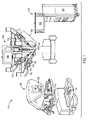
図1を見ると、本明細書に記載された実施例にしたがった手術器具を採用できる遠隔操作手術システム100の例が示されている。例えば、Intuitive Surgical社から市販されているDa Vinci(登録商標) Surgical Systemであってもよいシステム100は、複数の手術器具140を有する患者側カート102を含む。複数の手術器具140のそれぞれは、ロボットアーム110のドッキングポートに取り付けられる。手術器具140は取り換え可能であってもよい。所要の臨床的機能をもたらすべく、アーム110に取り付けられた手術器具140が特定の医療処置のために選択され、或いは、医療処置中に変更され得るようにするためである。この分野でよく知られているように、手術器具140は、例えば、鉗子(forceps)若しくは補足器具(graspers)、持針器(needle drivers)、外科用メス(scalpels)、はさみ(scissors)、焼灼器具(cauterizing tools)、及びステープラー(staplers)を含むがそれらには限定されない多くの機能を実現させ得る。
Turning to FIG. 1, an example of a remotely operated
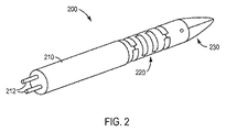
器具140のそれぞれは、概して、伝達・バックエンド機構150、伝達機構150から延びるメインシャフト160、メインシャフト160の遠位端におけるオプションのリスト機構(図1では図示せず。)、及び、リスト機構から或いはシャフト160から直接的に延びるエンドエフェクタ180を含む。図2は、シャフト210、シャフト210の遠位端におけるリスト220、及び、リスト220から延びるエンドエフェクタ230を含む手術器具の遠位端200を示す。
Each of the
図2に示すように、例えばプル/プル式テンドン(tendon)若しくはプッシュ/プル式ロッド、並びに、器具のリスト機構220及び/若しくはエンドエフェクタ230に接続される導体のような作動要素212は、器具のシャフト210を通じて延び得る。更に、作動要素は、メインシャフト160を通じて延び、伝達機構150につながっていてもよい。伝達機構150は、典型的には、患者側カート102における駆動モータへの駆動テンドンの機械的結合をもたらす。例えば、伝達機構150は、患者側カート102のアーム110の患者側マニピュレータ112につながるように構成されてもよい。
As shown in FIG. 2, the
作動インタフェースは、概して、手術器具140の作動のための機械力をもたらす駆動モータを含んでいてもよい。このようにして、システム100は、リスト機構を動かし或いは位置決めしてエンドエフェクタ180を作動させるために、必要に応じて、テンドンの動き及び張力を制御できる。患者側カート102のアーム110は、医療処置を受けている患者の小切開におけるカニューレを通じて手術器具140の端部を挿入するために、且つ、患者の体内の作業場で器具140のリスト機構及び/又はエンドエフェクタ180を作動させるために用いられてもよい。
The actuation interface may generally include a drive motor that provides mechanical force for actuation of the
同様に、カメラ器具104は、カート102のアームに取り付けられてもよく、またオプションで、作業場の観察及び患者の体内での手術器具140の動きの観察のためのカメラシステム104の遠位端を位置決めするためにシステム100が作動させるリスト機構を有していてもよい。立体的若しくは3次元的であってもよいカメラシステム104からの表示は、制御コンソール(図示せず)で見ることができ、また、画像はモニタ106に表示されてもよい。このようにして、システム100の処理システムは、医師又は他の医療関係者がカメラシステム104及び器具140を見て操作できるようにするユーザインタフェースを提供できる。例えば、手術器具140と同様に、アーム110は、医療処置を受けている患者の小切開におけるカニューレを通じてカメラ器具104の端部を挿入するために、且つ、患者の体内の作業場でリスト機構及び/又はエンドエフェクタ180を作動させるために用いられてもよい。
Similarly, the camera instrument 104 may be attached to the arm of the
手術器具140に関するメインシャフト160、リスト機構、及びエンドエフェクタ180の径若しくは径群、並びに、カメラ器具104の径は、大抵、その器具と共に用いられるカニューレのサイズに応じて選択される。典型的な実施例では、カメラ器具104の径、並びに、リスト機構及びメインシャフト160の径は、約3mmから約13mmの範囲であってもよい。例えば、その径は、いくつかの既存のカニューレシステムのサイズに合うように、約4mmであってもよく、約5mmであってもよく、或いは、約8mmであってもよい。
The diameter or group of diameters of the
図1の概略図に示すように、遠隔操作手術システム100は、医者コンソール120及び補助的な制御/観察カート130を更に含んでいてもよい。概して、医者コンソール120は、例えば外科医であるユーザからの入力を、グリップ機構122及び足踏みペダル124を含むがそれらに限定されない種々の入力装置で受け、且つ、手術器具140の所望の動きを実行するために、患者側カート102に取り付けられた器具140が応答するマスタコントローラとしての機能を果たし、且つ、それに応じて所望の医療処置を実行する。例えば、グリップ機構122は、限定的ではないものの、手術器具140及び/又はカメラ器具104を制御できる“マスタ”装置としての機能を果たしてもよい。手術器具140及び/又はカメラ器具104は、ロボットアーム110において、対応する“スレーブ”装置としての機能を果たしてもよい。例えば、グリップ機構122は、当業者がよく知っているように、手術器具140のエンドエフェクタ180及び/又はリストを制御してもよい。更に、足踏みペダル124は、限定的ではないものの、例えば単極又は双極の電気外科的エネルギをもたらすために踏み込まれてもよく、或いは、器具140の他の様々な機能(例えば、吸引、潅注、及び/又は、他の様々なフラックス供給モード)を作動させるために踏み込まれてもよい。言い換えると、例えば医者コンソール120のところにある入力装置に供給されたコマンドに基づいて、患者側カート102は、アーム110のところにある患者側マニピュレータ112を用いて所望の医療処置を実行するために器具140、104を位置決めして作動させることができる。このようにして、患者側カート102の器具140、104は、医者コンソール120でユーザによって入力されたコマンドにしたがって遠く離れて遠隔操作され得る。医者コンソール120は、例えば外科的処置の際に、例えば患者側カート102のところにあるカメラ器具104を用いて手術部位の3次元画像を医者が見られるようにするディスプレイを更に含んでいてもよい。
As shown in the schematic diagram of FIG. 1, the teleoperated
遠隔操作手術システムの非限定的な典型的な実施例では、制御/観察カート130は、コアプロセッサ134等の“コア”処理装置、及び/又は、制御/観察カート130に組み込まれ或いは制御/観察カート130のところで物理的に支持され得る他の補助的な処理装置を含む。制御/観察カート130は、手術システムを作動させるための他のコントロールを含んでいてもよい。典型的な実施例では、医者コンソール120から発せられた信号又は入力は、制御/観察カート130のところにある1又は複数のプロセッサに伝達され得る。制御/観察カート130は、1若しくは複数の手術器具140及び/又は患者側カート102で手術器具140が結合されるところであるアーム110の操作をもたらすために、その入力を解読し、且つ、患者側カート102に伝達されるコマンド又は出力を生成できる。図1のシステム構成要素は特別な位置決めで示されているわけではなく、患者の手術に影響を与えるべく患者に関連して患者側カート102が配置されるようにしながら、要望通りに配置されてもよい点に留意すべきである。
In a non-limiting exemplary embodiment of a teleoperated surgical system, the control /
リストジョイントのような手術器具ジョイントは、そのジョイントを含む手術器具又はカメラ器具に動きをもたらすべく、1又は複数の自由度にしたがって動いてもよい。例えば、ジョイントは、(例えばピッチ及び/又はヨーとして任意に定められる)1又は複数の自由度で互いに対して動き得る複数の部材を含んでいてもよい。手術器具又はカメラ器具のジョイントは、様々な数の部材を含んでいてもよい。例えば、手術器具又はカメラ器具のジョイントは、1ピースのジョイントであってもよく、2ピースのジョイントであってもよく、3ピースのジョイントであってもよく、或いは、より大きな数のピースを含むジョイントであってもよい。1ピースのジョイントは、例えばそのピースに備えられた構造的に柔軟な部分のために、1又は複数の方向に曲がるように設計された単一ピースのものである。2ピースのジョイントは、例えば、互いに直接的に接続される、椎骨とも呼ばれ得る2つのディスクである。3ピースのジョイントは、例えば、2つのディスクとそれら2つのディスクを接続する3番目のピースである。 A surgical instrument joint, such as a wrist joint, may move according to one or more degrees of freedom to provide movement to a surgical instrument or camera instrument that includes the joint. For example, a joint may include a plurality of members that can move relative to each other in one or more degrees of freedom (eg, arbitrarily defined as pitch and / or yaw). A surgical instrument or camera instrument joint may include a variable number of members. For example, a surgical instrument or camera instrument joint may be a one-piece joint, a two-piece joint, a three-piece joint, or include a larger number of pieces. It may be a joint. A one-piece joint is a single piece designed to bend in one or more directions, for example because of the structurally flexible portion provided on the piece. A two-piece joint is, for example, two discs, also called vertebrae, that are directly connected to each other. The three-piece joint is, for example, two disks and a third piece that connects the two disks.
以下の説明は、手術器具での適用という状況におけるジョイントの構成を説明するが、そのジョイントの構成はカメラ器具にも適用され得ることを当業者は理解するであろう。更に、以下の説明は、2ピースのジョイントであるジョイントの構成を説明するが、その説明の概念は、3ピースのジョイント又はより大きな数のピースを含むジョイントのような、より多くの数のピースを含むジョイントにも適用され得る。 Although the following description describes a joint configuration in the context of application with a surgical instrument, those skilled in the art will appreciate that the joint configuration can also be applied to a camera instrument. In addition, the following description describes a joint configuration that is a two-piece joint, but the concept of the description is a larger number of pieces, such as a three-piece joint or a joint that includes a larger number of pieces. It can also be applied to joints containing.
本書に記載される典型的な実施例のジョイント部材は、例えば、参照によりその全部が本書に援用されるWilliams氏の米国特許出願公開第2011/0152879号に記載されるようなサイクロイドの表面形状を有する特徴を含んでいてもよい。サイクロイド形状を有するジョイント部材は、例えば複数のジョイント部材が一緒に圧縮された場合に、より一般的なインボリュート形状を有するジョイント部材と比べ、詰まり(jamming)を起こしにくい。また、米国特許出願公開第2011/0152879号の図3に示された外サイクロイド310及び内サイクロイド320は、凹状及び凸状の接触域を含み、外サイクロイド310と内サイクロイド320の間で力を分散するための比較的大きな接触域をもたらす。結果として、サイクロイド面間の圧力(stress)は与えられた荷重に対して低減され、それらサイクロイド面は低減された荷重変形を受け得る。 Exemplary embodiment joint members described herein may have, for example, a cycloidal surface shape as described in Williams U.S. Patent Application Publication No. 2011/0152879, which is incorporated herein by reference in its entirety. It may include features that it has. A joint member having a cycloid shape is less likely to jam when compared to a joint member having a more general involute shape, for example, when a plurality of joint members are compressed together. In addition, the outer cycloid 310 and the inner cycloid 320 shown in FIG. 3 of US Patent Application Publication No. 2011/0152879 include concave and convex contact areas, and the force is distributed between the outer cycloid 310 and the inner cycloid 320. Resulting in a relatively large contact area. As a result, the stress between the cycloid surfaces is reduced for a given load and the cycloid surfaces can undergo reduced load deformation.
Williams氏の米国特許出願公開第2011/0152879号で説明されるように、リスト機構におけるギア動作は、リスト機構における2つの部材が固定関係又はギア比に応じて変化する相対角度方向を有する場合に生じる。米国特許出願公開第2011/0152879号の図1A及び図1Bに示すように、リストジョイント100の部材110、120は、それぞれ、円形の負担面112、122を有し、部材110、120が互いに対して回転するときのギア動作の際に面112、122が互いに転がることができるようにする。部材110は、例えば部材110と部材120との間の並進運動によるスリップを防止するために、部材120の開口部(凹部)124の壁と係合可能な歯114を含んでいてもよい。歯114と開口部124の壁との組み合わせは、ピン・ギアと呼ばれてもよい。それ故に、ジョイントは、複数のジョイント部材の互いに対する並進を最小限に抑え或いは排除するための特徴を含んでいてもよい。手術器具のリストのような手術器具は、このようにして曲がる複数のジョイントを含んでいてもよい。例えば、手術器具は、例えばピッチ方向及びヨー方向に曲がることで手術器具の動きに関する複数の自由度をもたらすために、互いに対して方向を定められる複数のジョイントを含んでいてもよい。
As described in Williams U.S. Patent Application Publication No. 2011/0152879, the gear motion in the wrist mechanism is when the two members in the wrist mechanism have a relative angular orientation that varies depending on the fixed relationship or gear ratio. Arise. As shown in FIGS. 1A and 1B of US Patent Application Publication No. 2011/0152879, the
典型的な実施例によると、ジョイント部材間の並進を最小限に抑え或いは排除するために用いられるジョイント部材の特徴は、ジョイント部材の繰り返し運動も改善できる。例えば、米国特許出願公開第2011/0152879号の図1A及び図1Bで示すように、例えば手術器具のリストを曲げるために部材110、120が互いに対して回転させられた後で、ユーザは、例えば部材110、120の回転を逆転させることによってそのリストを真っ直ぐにしたいかもしれない。横方向及び/又は手術器具の長手軸に沿った方向における部材110、120の互いに対する実質的な変位を何れかの回転がもたらした場合、部材110、120の互いに対するその後の運動は、円滑さに劣るものとなり得る。更に、部材110と部材120との間の実質的な変位は、部材110と部材120との間の動きの制御に影響を与える場合があり、ユーザは、その変位を観察するかもしれない。部材110、120のそれぞれに歯114及び開口部124を備えることで、部材110、120の繰り返し運動は、最小限の並進で実現され得る。このようにして、ジョイント部材は、実質的に反復可能な運動を有するように構成され得る。ジョイント部材を実質的に元の位置に戻すことで運動を繰り返すというジョイント部材のこの能力は、ジョイントのタイミング(timing)と呼ばれてもよい。例えば、部材110の歯114と部材120の開口部124とは、米国特許出願公開第2011/0152879号の図1Aにおける典型的な実施例で示す中立状態のような元の位置に部材110、120を実質的に戻すタイミングをもたらすための構造としての機能を果たしてもよい。
According to an exemplary embodiment, the features of the joint members used to minimize or eliminate translation between the joint members can also improve the repetitive movement of the joint members. For example, as shown in FIGS. 1A and 1B of US Patent Application Publication No. 2011/0152879, after
米国特許出願公開第2011/0152879号における部材110の歯114と部材120の開口部124とによってもたらされるピン・ギアのようなジョイントディスクのピン・ギアでは、ピン・ギアを含む隣接するディスク間で許容される最大回転量は、例えば、ジョイントの長手軸に関して±45度程度に限定されてもよい。例えば±90度程度までである最大可動域は、ピン・ギアを含む2セットのディスクジョイントを用いることによって、手術器具のリストの総体的運動に関して実現され得る。ディスクジョイントの各セットは、ジョイントの長手軸に関して±45度の最大回転をもたらす。しかしながら、2セットのディスクジョイントの使用は、追加的な製造コストを課し、且つ、1つの手術器具のために、バックエンドの構成要素における複数の制御ケーブルと複数のモータといった、他の追加的な部品を必要とする。これらの検討に鑑み、例えば±45度程度よりも大きい比較的大きな最大可動域を有するリストジョイントを提供することが望ましいこととなり得る。それ故に、そのようなリストジョイントでは、±45度程度以上の制御された関節運動をもたらすことができる。また、円滑な動きが可能で且つ“タイミング”を実現するリストを提供することが望ましい。
In a pin gear of a joint disk such as a pin gear provided by the teeth 114 of the
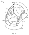
図3を見ると、手術器具のリストのためのジョイント400の典型的な実施例が示されている。ジョイント400は、図3に示すように、第1ディスク410と第2ディスク420とを含む。このように、典型的な実施例によると、ジョイント400は、第1ディスク410と第2ディスク420とが互いに直接的に接触する2ピースのジョイントであってもよい。例えば、ディスク410、420は、ディスク410とディスク420との間に置かれる追加的なジョイント構成要素の存在無しに直接的に接触し得る。用語“ディスク”は、椎骨状の構造を表現するときに頻繁に用いられるように広い意味で用いられる。当業者は、ジョイントのディスク構成要素が円形断面又は円環形状に限定されない様々な形状及び構成を有し得ることを理解するであろう。
Turning to FIG. 3, an exemplary embodiment of a joint 400 for a list of surgical instruments is shown. As shown in FIG. 3, the joint 400 includes a
米国特許出願公開第2011/0152879号の部材110、120のような単一の歯とそれに対応する開口部のみを含むジョイント部材とは対照的に、ジョイント400は、互いにかみ合うジョイント特徴411、421をそれぞれ有するディスク410、420を含んでいてもよい。例えば、第1ディスク410のジョイント特徴411は、図3の典型的な実施例で示すように、第1歯412及び第2歯414を含んでいてもよい。但し、例えば3つ、4つ、或いはそれ以上の数の歯といった、他の数の歯が用いられてもよい。第2ディスク420のジョイント特徴421は、図3に示すように、歯412、414とかみ合うように構成される第1ピン422、第2ピン424、及び第3ピン426を含んでいてもよい。但し、例えば4つ、5つ、或いはそれ以上の数のピンといった、他の数のピンが用いられてもよい。典型的な実施例によれば、ピン422、424、426はそれぞれ一定の曲率半径を有していてもよい。ピンの曲率半径は、ディスクの隣接部分とは異なるものであってもよい。結果として、ピンは互いに径が異なるものであってもよい。
In contrast to a joint member that includes only a single tooth and its corresponding opening, such as
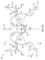
ピンの曲率半径は、図11Aの典型的な実施例で示されている。図11Aは、ピン中心923、925、927に関して曲率半径960、962、964を有するピン922、924、926を含むディスク920を示す。図11Aの典型的な実施例で示すように、ピン922、926に隣接するディスク部分970、972は、異なる曲率半径を有し、それ故に、ピン922、926とは異なる形状を有する。同様に、ピン924に隣接するステム943は、異なる曲率半径を有し、それ故にピン924とは異なる形状を有する。更に、ピン922、924、926のそれぞれは同じ曲率半径960、962、964を有するが、半径960、962、964は互いに異なるものであってもよい。例えば、半径960、962、964のそれぞれは異なるものであってもよく、或いは、半径960、962、964のうちの少なくとも1つは他とは異なるものであってもよい。一例では、半径960と半径964は同じであってもよいが、半径962とは異なるものであってもよい。
The radius of curvature of the pin is shown in the exemplary embodiment of FIG. 11A. FIG. 11A shows a
典型的な実施例によれば、歯とピンは、参照により本書に援用された米国特許出願公開第2011/0152879号に記載されているサイクロイド形状を有していてもよい。図16を見ると、サイクロイド形状の歯1412を有するディスク1410と、サイクロイド形状のピン1422、1424を有するディスク1420とを含むジョイント1400の典型的な実施例が示されている。しかしながら、ジョイントのディスクは、単一の歯と2つのピンに限定されるものではなく、その代わりに、サイクロイド形状を有する2つ、3つ、或いはそれ以上の数の歯と、サイクロイド形状を有する3つ、4つ、或いはそれ以上の数のピンとを含んでいてもよい。例えば、図17の典型的な実施例は、サイクロイド形状の2つの歯1512、1514を有するディスク1510と、サイクロイド形状のピン1522、1524、1526を含むディスク1520とを含むジョイント1500を示す。
According to an exemplary embodiment, the teeth and pins may have a cycloid shape as described in US Patent Application Publication No. 2011/0152879, which is incorporated herein by reference. Turning to FIG. 16, an exemplary embodiment of a joint 1400 is shown that includes a
典型的な実施例によると、ディスク410は、図3に示すように、近位−遠位方向470に関するディスク410の端部のそれぞれに複数の歯を含んでいてもよい。同様に、ディスク420は、近位−遠位方向470に関するディスク420の端部のそれぞれに複数のピンを含んでいてもよい。種々の典型的な実施例では、その端部のそれぞれにおける複数の歯若しくは複数のピン、又は、一端における複数の歯と他端における複数のピンであってもよいジョイント特徴をディスクが含む場合、図3の典型的な実施例で示すように、その反対端にある歯又はピンは、約90度だけ周方向に互いにオフセットされていてもよい。
According to an exemplary embodiment, the
ジョイント400は、複数の歯を有する少なくとも1つのディスクを含むため、ジョイント400は、第1ディスク410と第2ディスク420との間に改善された可動域をもたらす。例えば、ジョイント400は、図4に示すように、例えば任意のピッチ又はヨー運動等のために、例えばディスク410、420が方向430において互いに対して回転させられたときに、第1ディスク410と第2ディスク420との間で±45度より大きい(ロール角リミットまでの)最大可動域をもたらし得る。別の実施例によると、ジョイント400は、第1ディスク410と第2ディスク420との間で±45度程度よりも大きく±75度程度までの最大可動域をもたらし得る。別の実施例によると、ジョイント400は、第1ディスク410と第2ディスク420との間で±45度よりも大きく±80度程度までの最大可動域をもたらし得る。別の実施例によると、ジョイント400は、第1ディスク410と第2ディスク420との間で±75度よりも大きく±90度程度までの最大可動域をもたらし得る。別の実施例によると、ジョイント400は、第1ディスク410と第2ディスク420との間で±60度程度から±80度程度の最大可動域をもたらし得る。ジョイント400は、第1ディスク410と第2ディスク420との間で±45度より大きく±90度程度までの最大可動域(ローク角リミット)、又は、第1ディスク410と第2ディスク420との間で±60度程度から±90度程度の最大可動域といった、第1ディスク410と第2ディスク420との間での更に大きな可動域をもたらし得る。しかしながら、第1ディスク410と第2ディスク420との間で更に大きな可動域(ロール角リミット)が実現されてもよい。
Since joint 400 includes at least one disk having a plurality of teeth, joint 400 provides an improved range of motion between
ジョイント400によってもたらされる改善された可動域のため、ジョイント400を含むリストは、より少ない部品によるより効率的な方法で、ピッチ又はヨー方向における±90度といった、所望の大きさの運動をもたらし得る。約45度の最大ロール角に各ジョイントが制限されている以前のリスト構造では、直列に接続されたいくつかのそのようなジョイントが、リスト機構全体の比較的大きなロール角のために必要とされる。しかし、本発明の態様によると、構造の全体的な可動域よりも限られた可動域を各ジョイントが有する構造で比較的大きな可動域を実現するために、ジョイント(及びディスク)が少なくて済む。そして、図示されるように、単一のジョイントが最大で90度のロール角リミットをもたらすことができる。同じロール角を実現するためには45度のロール角リミットを有する2つのジョイントが必要とされる。また、単一ジョイントの実施形態は、小さな手術部位におけるエンドエフェクタのより良いアクセスを可能にする、より短いエンドエフェクタのスロー距離(throw distance)を有する。エンドエフェクタのスロー距離は、器具のシャフトの中心線からエンドエフェクタの先端までの距離である。結果として、所望の関節制御を実現しながらも、1又は複数のジョイント400を含むリストの製造コスト及び複雑さが低減され得る。また、ジョイント400のディスク410、420に含まれる複数の歯とそれに対応する複数のピンは、例えば、中立位置にディスクを戻すこと(例えば、ゼロ角ロールアライメント)を含め、ディスク410、420を正確に位置決めすることを支援するための、且つ、例えばディスク410、420が方向430において互いに回転させられたときのディスク410とディスク420の間の動きの滑らかさを改善するための、改善されたタイミングをもたらすことができる。また、単一ジョイントの実施形態は、器具のシャフトの中心線からエンドエフェクタの先端までのエンドエフェクタのスロー距離がより短く、小さな手術部位でのエンドエフェクタのより良いアクセスを可能にする。典型的な実施例によると、リストは、例えば、ピッチ又はヨー方向における±180度までの可動域を有するリストのように、(ロールリミット角までの)より大きな可動域を実現するために、複数のジョイント400を含んでいてもよい。図15の典型的な実施例に示すように、リスト1300は、より大きな可動域を実現するために、第1ディスク1310及び第2ディスク1320を含む第1ジョイント1302と、第3ディスク1330及び第4ディスク1340を含む第2ジョイント1304とを含んでいてもよい。
Because of the improved range of motion provided by the joint 400, the list including the joint 400 can provide a desired amount of motion, such as ± 90 degrees in the pitch or yaw direction, in a more efficient manner with fewer parts. . In previous wrist structures where each joint is limited to a maximum roll angle of about 45 degrees, several such joints connected in series are required for a relatively large roll angle of the entire wrist mechanism. The However, according to an aspect of the present invention, fewer joints (and disks) are required to achieve a relatively large range of motion in a structure in which each joint has a range of motion limited than the overall range of motion of the structure. . And as shown, a single joint can provide a roll angle limit of up to 90 degrees. To achieve the same roll angle, two joints with a 45 degree roll angle limit are required. The single joint embodiment also has a shorter end effector throw distance that allows better access of the end effector at a small surgical site. The end effector throw distance is the distance from the centerline of the instrument shaft to the tip of the end effector. As a result, the manufacturing cost and complexity of a list including one or
また、ジョイント特徴は、ジョイントの歯とピンが互いにかみ合うのを支援するための他の構成を含んでいてもよい。典型的な実施例によると、図3及び図4に示すように、ディスク410の歯412と歯414との間に凹部416が備えられてもよい。凹部416は、ディスク420の中央ピン424を受け入れるように形成されている。更に、ディスク420のジョイント特徴421は、歯412、414を受け入れるための凹部を含んでいてもよい。例えば、図3及び図4に示すように、凹部423は、歯412を受け入れるために、ピン422とピン424の間に位置付けられてもよく、凹部425は、歯414を受け入れるために、ピン424とピン426の間に位置付けられてもよい。ピン424を受け入れるための凹部416と、歯412、414を受け入れるための凹部423、425を備えることは、例えば、歯412、414とピン422、424、426とが互いの間でより遠くに延びるようにすることができるといった、歯412、414とピン422、424、426とのより緊密な結合を可能にする。結果として、ディスク410とディスク412との間の動きは更に滑らかなものとされ、ジョイント400のタイミングは改善され得る。例えば、図4の典型的な実施例で示すようにディスク410、412が互いに回転させられた後で、図3の典型的な実施例で示す真っ直ぐな形態に実質的に戻るためのディスク410、412の能力は改善され得る。これは、例えば複数のサイクルにわたって実質的に同じ態様で図4に示す回転を繰り返すジョイント400を含むリストの能力を改善し得る。
The joint features may also include other configurations to assist in engaging the teeth and pins of the joint. According to an exemplary embodiment, a
典型的な実施例によると、図3及び図4に示すように、ピン凹部413、415が、歯412、414の横にある位置、すなわちディスク410、412の外側にある位置に設けられてもよい。ピン凹部413、415は、ディスク410、412が互いに対して回転させられたときにピン422、426を受け入れるように構成され得る(図4では凹部415がピン426を受け入れている。)。結果として、ピン凹部413、415は、例えば±75度程度まで或いはそれ以上といった比較的大きな可動域でディスク410、412が互いに対して回転させられたときでさえも、歯412、414とピン422、424、426との間のかみ合いの改善を支援し得る(言い換えれば、図4に示すように、ピン426とピン424との間の凹部内に歯414を維持する。)。
According to an exemplary embodiment, as shown in FIGS. 3 and 4, pin recesses 413, 415 may be provided at positions next to
典型的な実施例によると、複数の歯を含むジョイント部材は、ジョイントの関節接合の際に、対応するピンとのかみ合いが解除される歯を少なくとも1つ有していてもよい。歯及びピンのようなジョイント特徴を説明するときに本書で用いられる、かみ合い(intermesh)及び係合(engage)は、ジョイント特徴が接触していることを必ずしも意味しない。以下で説明するように、歯及びピンといったジョイント特徴は、標準状態では互いに間隔を空けられていて接触していなくてもよく、或いは、ジョイント特徴は、例えば圧縮荷重を受ける面を提供するために、標準状態で互いに接触していてもよい。例えば、歯とピンは、かみ合わせられ或いは係合させられたときは、標準状態の際には通常は接触しておらず、例えば横力及び/又はトルクがディスクを互いに対して横方向にシフトさせた場合等、後で歯とピンが互いに接触するようにしてもよい。また、歯とピンは、特にディスクが互いに対して既に回転させられているときに、ディスクが長手方向に沿って互いに対してシフトしたときに、互いに接触してもよい。これが生じた場合、少なくとも1つの歯と1又は複数のピンとの間のギャップが閉じ、かみ合わされた歯と1又は複数のピンとを互いに接触させ、ディスク間の更なる横運動及びジョイントの潜在的な脱臼を実質的に防止する。結果として、ディスクの相対位置は維持される。そして、かみ合わされた或いは係合されたジョイント特徴が通常時に互いに接触しない場合でさえ、ディスクを含むジョイントのタイミング、及び、横方向におけるディスクの動きに関する自由度の極小化又は排除を改善する。別の例では、かみ合わされた或いは係合された歯とピンは、例えば歯とピンのそれら自体が荷重負担面としての機能を果たす場合では、通常時に互いに接触していてもよい。例えば、図16及び図17の典型的な実施例では、歯1412、1512、1514とピン1422、1424、1522、1524、1526は、それら自体が、追加的な荷重負担突起なしで、荷重負担面としての機能を果たし得る。
According to an exemplary embodiment, a joint member including a plurality of teeth may have at least one tooth that is disengaged from a corresponding pin when the joint is articulated. Intermesh and engagement used herein when describing joint features such as teeth and pins does not necessarily mean that the joint features are in contact. As described below, joint features such as teeth and pins may be spaced apart and not in contact with each other in the standard state, or the joint features may provide surfaces that are subject to compressive loads, for example. They may be in contact with each other in the standard state. For example, when teeth and pins are engaged or engaged, they are not normally in contact under normal conditions, for example, lateral forces and / or torques cause the disks to shift laterally relative to each other. For example, the teeth and pins may come into contact with each other later. The teeth and pins may also contact each other when the disc is shifted relative to each other along the longitudinal direction, particularly when the disc is already rotated relative to each other. When this occurs, the gap between the at least one tooth and the one or more pins closes, bringing the meshed teeth and the one or more pins into contact with each other, further lateral movement between the disks and the potential of the joint Substantially prevent dislocation. As a result, the relative position of the disc is maintained. It also improves the timing of the joints that contain the disk and the minimization or elimination of freedom with respect to the movement of the disk in the lateral direction, even if the engaged or engaged joint features do not normally contact each other. In another example, meshed or engaged teeth and pins may be in contact with each other at normal times, for example when the teeth and pins themselves serve as load bearing surfaces. For example, in the exemplary embodiment of FIGS. 16 and 17, the
図3は、ジョイント400の中立状態でかみ合わされている歯とピンの典型的な実施例を示し、歯412がピン422及びピン424とかみ合い、歯414がピン424及びピン426とかみ合っている。更に、ピン424は、ピン凹部416に受け入れられてもよく、歯412、414は、それぞれ、歯凹部423、425に少なくとも部分的に受け入れられ且つそれらの外端に位置付けられていてもよい。図4の典型的な実施例で示すように、ディスク410、420が方向430に回転させられると、その回転は、対応するピン422、424から解放され且つ歯凹部423から外された歯412をもたらし得る。しかしながら、図4の姿勢では、ディスクの相対的な回転によって少なくとも1つの歯が解放されたときに、歯とピンがディスク410、420の位置決め及びタイミングに影響を与え続けるように、別の歯が、対応するピンとかみ合ったままとなり得る。例えば、方向430においてディスク410、420が互いに対して回転させられたときに、歯414はピン424及びピン426とかみ合ったままとなっていてもよい。更に、図4に示すように、歯414の大部分は、歯凹部425内に受け入れられている。
FIG. 3 shows an exemplary embodiment of teeth and pins that are engaged in the neutral state of joint 400, with
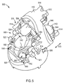
上述のように、ディスク410、420を含むジョイント400は、図2の典型的な実施例におけるリスト220のような手術器具のリストに備えられていてもよい。手術器具のリストで用いられる場合、ディスク410、420は、駆動テンドン(図示せず)によって一緒に引っ張られてもよい。そして、図1の典型的な実施例に関して説明したように、ジョイント400の動きを制御するために用いられてもよく、また、当業者がよく知っているように、リストの構成要素を一緒に保持するようにディスク410、420を互いに対して押し付けるために用いられてもよい。典型的な実施例によると、ディスク510は、図5に示すように、ディスク510を通過する1又は複数のテンドンを収容するために、対応する数のテンドン通路554を含んでいてもよい。同様に、ディスク520は、1又は複数のテンドン通路550を含んでいてもよい。典型的な実施例によると、ディスクは、例えばディスクの別々の部分がテンドンの意図された経路内に存在する場合等では、テンドン毎に2つ以上の通路を含んでいてもよい。例えば、ディスク520は、テンドン通路550と、ディスク520の別の部分における同じテンドンのための別のテンドン通路552とを含んでいてもよい。典型的な実施例によると、通路550、552は、ジョイント500の長手軸に実質的に平行に延びる方向に沿って互いに一直線になっていない。図5の典型的な実施例におけるテンドン通路550、552、554は、典型的な実施例にしたがってディスク510、520が互いに対して回転させられたときに、それら通路内でテンドンが前後に動けるように、テンドンの径より大きな径を有していてもよい。典型的な実施例によると、ディスクは、(例えばプッシュ/プル式作動部材が用いられるときのように)2つのテンドン通路を含んでいてもよく、3つのテンドン通路を含んでいてもよく、4つのテンドン通路を含んでいてもよく、或いは、より多くのテンドン通路を含んでいてもよい。
As described above, the joint 400 including the
テンドンがジョイントのディスクを一緒に保持する構成の重要性は、圧縮荷重がディスク間に適用される点にある。これらの圧縮荷重に対処するために、典型的なジョイント部材は、圧縮荷重を受けるための荷重負担面を含む1又は複数のジョイント特徴を含んでいてもよい。図5は、図3及び図4の典型的な実施例と同様の要素を有するが追加的なジョイント特徴も有するジョイントの別の典型的な実施例を示す。例えば、ディスク510は、圧縮荷重のような荷重を受けるように構成された荷重負担面546を有する1又は複数の負担突起544を含んでいてもよく、ディスク520は、図5に示すように、例えば突起544の面546とかみ合うことによって圧縮荷重を受けるように構成された荷重負担面542を有する1又は複数の負担突起540を含んでいてもよい。典型的な実施例によると、ディスク510とディスク520との間に圧縮荷重が適用される限り、ディスク510、520の互いに対する動きの間中ずっと、面542、546は、互いに接触したままとなるように構成されてもよい。
The importance of the configuration in which tendons hold the joint disks together is that compressive loads are applied between the disks. In order to address these compressive loads, a typical joint member may include one or more joint features that include a load bearing surface for receiving the compressive load. FIG. 5 shows another exemplary embodiment of a joint having elements similar to the exemplary embodiment of FIGS. 3 and 4 but also having additional joint features. For example, the
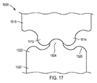
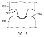
図5の典型的な実施例に示すように、負担突起540、544の面542、546は、部分円筒形状を有していてもよい。しかしながら、本書で説明された典型的な実施例の負担突起の面は、部分円筒に限定されず、その代わりに他の形状を有していてもよい。典型的な実施例によると、負担突起は、米国特許出願公開第2011/0152879号に記載されるようなサイクロイド形状の面を有していてもよい。例えば、米国特許出願公開第2011/0152879号に記載されるように、第1負担突起1610は、サイクロイド形状の面1612を有していてもよく、第2負担突起1620は、サイクロイド形状の面1622を有していてもよい。別の典型的な実施例によると、参照によりその全部が本書で援用される2004年11月16日に公開された米国特許第6817974号の典型的な実施例に記載されるように、負担突起は、支柱(strut)によってもたらされてもよい。支柱は、米国特許第6817974号に記載されるように、2つの隣接するディスクを繋ぐ別個のピースであり、それ故に、3ピース・ジョイントをもたらす別個のピースとして提供されてもよい。例えば、図19の典型的な実施例に示すように、ジョイント1700は、第1ディスク1710及び第2ディスク1720(それぞれが図19に概略的に示されている)と、ディスク1710とディスク1720の間に接続され且つそれらの間の荷重を受けるように構成された支柱1730とを含んでいてもよい。図19の典型的な実施例に示すように、支柱1730は、複数の突起1732と、複数の突起1732を繋ぐリング1734とを含んでいてもよい。ディスク1710及びディスク1720のそれぞれは、例えばディスク1720における複数の溝1722のような、支柱1730を介してディスク1710とディスク1720を接続すべく突起1732をかみ合わせるための特徴を含んでいてもよい。
As shown in the exemplary embodiment of FIG. 5, the
典型的な実施例によると、ディスク510は、図5に示す近位−遠位方向570に関するディスク510の各端部に負担突起544を含んでいてもよい。同様に、ディスク520は、ディスク520の各端部に負担突起540を含んでいてもよい。ディスクがその端部のそれぞれに負担突起を含む場合、両端にあるそれら突起は、図5の典型的な実施例に示すように、周方向において約90度だけ互いからオフセットされていてもよい。しかしながら、負担突起は、図5に示す構成に限定されず、その代わりに、例えばディスクを含むリストの可動域を増大させるために、互いからオフセットされる代わりにディスクの長手軸に沿って実質的に一直線となる配置を有していてもよい。
According to an exemplary embodiment, the
典型的な実施例によると、負担突起540及び負担突起544はそれぞれ、歯512、514とピン522、524、526を含むジョイント特徴511、512から分離されていてもよい。例えば、負担突起540は、図5に示すように、ピン522、524、526とは異なる、物理的に分離された部材であってもよい。突起540の面542は、ピン522、524、526によってもたらされる面とは異なる別個の面であってもよい。また、負担突起544及び負担面546は、図5に示すように、歯512、514とは異なる物理的に分離された部材であってもよく、また、突起544の面546は、歯512、514によってもたらされる面とは異なる別個の面であってもよい。典型的な実施例によると、突起540、544は、種々の制御テンドン、ロッド、及び他の器具構成要素が通過し得るディスク520の中央開口部560に関して、ピン522、524、526及び歯512、514とは異なる半径位置に位置付けられてもよい。典型的な実施例によると、図5に示すように、ピン522、524、526を含んでいてもよいジョイント特徴521よりもディスク520の中央開口部560に近いところに負担突起540が位置付けられるように、負担突起540は半径方向内側に位置付けられてもよい。同様に、歯512、514を含んでいてもよいジョイント特徴511よりもディスク510の中央開口部(図示せず)に近いところに負担突起544が位置付けられるように、負担突起544は半径方向内側に位置付けられてもよい。
According to an exemplary embodiment, the
歯512、514及びピン522、524、526及び負担突起540、544は、ディスク510、520の一部であってもよいが(すなわち、ディスク510、520と共に1ピース構造を有していてもよいが)、歯512、514及びピン522、524、526及び負担突起540、544は、そのような構成に限定されない。その代わりに、例えば、歯512、514、及び/又は、ピン522、524、526、及び/又は、負担突起540、544は、ディスク510、520に接続される別個のピースとして提供されてもよい。
上述のように、ディスクの歯及びピンは、図5の典型的な実施例で示すように歯512、514がピン522、524、526とかみ合わされているときであっても、標準状態の際に互いに間隔を空けて配置されてもよい。例えばジョイント500が横力及び/又はトルクを受けていないときのような標準状態において、例えば約0.0001インチのギャップが、歯512、514と、対応するピン522、524、526との間に提供されていてもよい。そのような構成では、突起540、544は、ディスク510とディスク520との間の圧縮荷重を受けるために用いられてもよい。歯512、514とピン522、524、526は、圧縮荷重を受けるように接触していなくてもよいためである。別の実施例によると、図3のジョイント400の歯412、414とピン422、424、426は、歯412、414とピン422、424、426がかみ合わされたときに、互いに接触していてもよい。結果として、歯412、414とピン422、424、426は、圧縮荷重のための負担面としての機能を果たしてもよい。歯とピンが負担面としての機能を果たす構成では、典型的な実施例にしたがって、荷重負担面としての負担突起は省略されてもよい。歯とピンが荷重負担面としての機能を果たすためである。上述のように、図16及び図17の典型的な実施例における歯1412、1512、1514とピン1422、1424、1522、1524、1526は、追加的な荷重負担突起無しで、それら自体が荷重負担面としての機能を果たしてもよい。
As described above, the disc teeth and pins are in a normal state, even when the
ジョイント部材は、上述の典型的な実施例で説明されたもの以外の種々の他の設計特徴を含んでいてもよい。例えば、図3及び図4を参照すると、図3及び図4の典型的な実施例で示すように、ディスク420のジョイント特徴421は、ディスク420のボディ472に関連する肩部462を形成してもよく、ディスク410のジョイント特徴411は、ディスク410のボディ474に関連する肩部466を形成する突起468を含んでいてもよい。例えば、ジョイント特徴421は、ディスク420のボディ472に関連する肩部462を形成する突起464に位置付けられてもよく、また、ジョイント特徴411は、ディスク410のボディ474に関連する肩部466を形成する突起468に位置付けられてもよい。肩部462、466は、ボディ472、474に対してほぼ直角を形成してもよい。ディスク410、420のボディ472、474はそれぞれ、図3及び図4に示すように、ディスク410とディスク420との間の可動域の限界までディスク420、410が互いに回転させられたときに互いに係合可能な傾斜面473、475を含んでいてもよい。このようにして、傾斜面473、475は、ディスク410とディスク420との間の回転を制限する制止部としての機能を果たすことができる。
The joint member may include various other design features other than those described in the exemplary embodiment above. For example, referring to FIGS. 3 and 4, as shown in the exemplary embodiment of FIGS. 3 and 4, the
また、歯及び/又は歯凹部は、比較的大きなものとなり、且つ、かみ合わされたときに大きな表面接触度をもたらすように構成されてもよい。横荷重によってより容易に係合が解除され得る、より多くの小さな歯の使用とは異なり、この大きな表面接触は、例えば比較的大きな横荷重の際等で、ディスク間のずれを最小限に抑えるのを支援できる。また、大きな表面接触は、ジョイントの長手軸回りの回転のような(ロールとは異なる)ディスク間の回転をも最小限に抑える。このように、ディスクの負担面間のずれ、及び、ディスクの相対的な軸回転を最小限に抑えることによって、リストは、手術中に受ける荷重の下で2つのディスクが互いに係合解除されることなく、(例えば、個々の構成のロール角リミットによって決まる45度より大きい90度までの)大きな角度で使用され得る。 Also, the teeth and / or tooth recesses may be relatively large and configured to provide a large degree of surface contact when engaged. Unlike the use of many smaller teeth, which can be more easily disengaged by a lateral load, this large surface contact minimizes disc-to-disk misalignment, for example, during relatively large lateral loads. Can help. Large surface contact also minimizes rotation between disks (as opposed to rolls), such as rotation about the longitudinal axis of the joint. In this way, by minimizing disc displacement between the bearing surfaces of the disc and the relative axial rotation of the disc, the wrist will disengage the two discs from each other under the load experienced during the operation. Without, it can be used at large angles (e.g. up to 90 degrees greater than 45 degrees as determined by the roll angle limit of the individual configuration).
別の典型的な実施例によると、ジョイント600は、図6に示すように、肩部又は肩部を形成するディスクボディからの突起を有しないディスク610、620を含んでいてもよい。ディスク610は、肩部の代わりに、ディスク610の側部にある傾斜面632から延びる歯612、614を含んでいてもよい。同様に、ディスク620は、ディスク620の側部にある傾斜面630から延びるピン622、624、626を含んでいてもよい。例えば、歯612、614は、傾斜面632から直接延びてもよく、また、ピン622、624、626は、傾斜面630から直接延びてもよい。ディスク610、620は、図3及び図5の典型的な実施例のディスク410、420に関して説明した、突起540、544及び凹部413、415、416、423、425のような他の特徴を含んでいてもよい。
According to another exemplary embodiment, the joint 600 may include
図5の典型的な実施例を参照して図示し且つ説明したように、ディスク520、510の負担突起540、544はそれぞれ、半径方向に沿ってピン522、524、526及び歯512、514よりも中央開口部560に近いところに位置付けられてもよい。そのような構成は、図5に示すように、ディスク510、520が互いに対して回転させられたときに、歯512、514とピン522、524、526との間に隙間553をもたらし得る。ディスク510、520が周囲環境にさらされるところである手術器具のリスト又は他の構成要素でジョイント500が用いられる場合、ディスク510、520の比較的大きな回転を考慮に入れたとしても、歯512、514とピン522、524、526との間の隙間を最小限に抑え或いは排除するようにディスク510、520を設計することが望ましいこととなり得る。例えば、歯とピンの間の隙間553は、周囲環境からの物質が隙間553に入るのを可能にする。それは、ジョイントの関節接合を潜在的に妨げる可能性がある。
As shown and described with reference to the exemplary embodiment of FIG. 5, the bearing
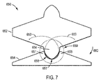
図7を見ると、第1ディスク652及び第2ディスク654を含むジョイント650の典型的な実施例が示されている。ディスク652は歯656を含んでいてもよく、ディスク654はピン651、655を含んでいてもよい。典型的な実施例によると、歯656を受け入れるように構成されたディスク654の凹部658は、歯とピンの間の隙間を最小限に抑え或いは排除するためにトロコイド形状を有していてもよい。図7の典型的な実施例で示すように、歯656の先端657は、第1ディスク652及び第2ディスク654が互いに対して回転させられたときに曲線653を描き得る。曲線653の端は、曲線653の形状がよりはっきりするようディスク652とディスク654の間の物理的な可動域の限界を超えて延ばされている。ジョイント650におけるトロコイド形状を有する凹部658を用いることによって、歯656と凹部658の間の隙間は、特にジョイント650が単一の歯656を含む場合に、最小限に抑えられ或いは除去され得る。例えば図3−図5の典型的な実施例等で示すようにジョイントが複数の歯を含む場合には、特にジョイントが大きな可動域まで作動させられたときに、歯とピンの間にギャップ又は他の外れ(misalignment)が生じる場合がまだある。
Turning to FIG. 7, an exemplary embodiment of a joint 650 that includes a
図8を見ると、図7における方向660に最大限にディスク652、654が互いに対して回転させられた後の領域659の拡大図が示され、歯656は、凹部658の表面にかみ合ったままとなっている。例えば、歯656の先端657は、図8に示すように、特にジョイント650が小さい数の歯を含む場合に、凹部658内に受け入れられたままとなり得る。更に、歯656とピン651、655の間(及び、歯656と凹部658の表面との間)のギャップは、(例えば、横力及び/又はトルクがジョイント650に適用されない場合の)標準状態で歯656とピン651、655が互いに接触しない場合等に、小さいままとなり得る。それ故に、ディスク652、654が中立位置に向かって逆向きに回転するときに、周囲環境からの物質が入る可能性がある歯656とピン651、655の間の隙間を最小限に抑え或いは排除できる。
Turning to FIG. 8, an enlarged view of the
歯とピンの間の隙間に対処する別の方法は、歯とピンとの間の隙間の周囲環境に対する露出を減らすことである。図5の典型的な実施例では、ディスク520、510の負担突起540、544はそれぞれ、中央開口部560に関し、ピン522、524、526及び歯512、514の半径方向の内側にあってもよい。結果として、歯512、514及びピン522、524、526は、ディスク510、520の外周に位置付けられ、且つ、歯512、514とピン522、524、526の間の隙間553は、例えばディスク510、520が互いに対して回転させられた場合等に、周囲環境にさらされ得る。別の典型的な実施例では、歯又はピンよりも中央突起からの半径方向距離が大きいところに負担突起が位置付けられていてもよい。
Another way to deal with the gap between the tooth and the pin is to reduce the exposure of the gap between the tooth and the pin to the surrounding environment. In the exemplary embodiment of FIG. 5, the bearing
図9を見ると、第1ディスク710及び第2ディスク720を含むジョイント700の典型的な実施例が示されている。ディスク710は、図5の典型的な実施例に関して説明したように、歯712、714及び負担突起744を含んでいてもよい。しかし、負担突起744は、歯712、714に対して外側の位置にある。例えば、負担突起744は、中央開口部761からの半径方向距離が歯712、714よりも大きいところに位置付けられてもよい。ディスク720は、図5の典型的な実施例に関して説明したように、ピン722、724、726と負担突起740を含んでいてもよい。しかし、負担突起740は、ピン722、724、726に対して外側の位置に位置付けられている。例えば、負担突起740は、ディスク720の中央開口部762からの半径方向距離がピン722、724、726よりも大きいところに位置付けられてもよい。結果として、歯712、714とピン722、724、726は、ディスク710、720の外周に位置付けられることはなく、負担突起740、744は、図5の典型的な実施例に比べ、歯712、714とピン722、724、726の間の隙間が周囲環境にさらされにくくなるよう、歯712、714とピン722、724、726をある程度は保護できる。
Turning to FIG. 9, an exemplary embodiment of a joint 700 that includes a
典型的な実施例によると、ディスク710、720の突起740、744は、図5の典型的な実施例で示したテンドン通路550、552、554のような、テンドンがディスク710、720を貫通できるようにするテンドン通路を含んでいてもよい。図10を見ると、図9の典型的な実施例にしたがって構成されてもよいディスク810、820を含むジョイント800の典型的な実施例が示されている。ディスク810、820はそれぞれ、負担突起812、822を含んでいてもよい。負担突起812、822が中央開口部814、824に対して外側位置に位置付けられているため(負担突起812、822が半径方向外側で且つディスク810、820の外面に近いところに位置付けられていてもよい)、負担突起812、822における通路を通って延びる駆動テンドン830もまた、外側位置に位置付けられている。駆動テンドン830がディスク810、820の外周に位置付けられ且つディスク810とディスク820の間に延びるため、テンドン830は、周囲環境からの物質に対する障壁を提供し且つそのような物質がディスク810、820の歯とピンの間の隙間に入るのを抑制し或いは排除することができる。
According to an exemplary embodiment, the
荷重面をもたらす負担突起に対して半径方向内側の位置に位置付けられた歯とピンを含むディスクの実施例に関する検討事項の1つは、ディスクの製造し易さである。例えば、負担突起の半径方向内側に歯とピンを位置付けることは、例えばディスクを成形し或いは機械加工する場合等で、負担突起に関して半径方向外側の位置に歯とピンが位置付けられるディスクの実施例に比べ、製造上の課題をもたらし得る。この検討事項に鑑み、種々の典型的な実施例は、例えば突起及び中央開口部に対して半径方向内側の位置に歯又はピンを含むディスクを含めた、ディスクの製造を容易にするように構成されたジョイントのためのディスクを検討している。 One of the considerations for the disk embodiment that includes teeth and pins positioned radially inward relative to the load projections that provide the load surface is the ease of manufacturing the disk. For example, positioning the teeth and pins radially inward of the burden protrusion is an example of a disk in which the teeth and pins are positioned radially outward with respect to the burden protrusion, for example, when the disk is molded or machined. In comparison, it can pose manufacturing challenges. In view of this consideration, various exemplary embodiments are configured to facilitate the manufacture of disks, including, for example, disks that include teeth or pins at locations radially inward of the protrusions and central opening. Discs for the joints made.
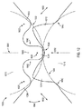
図11Aに示すように、ジョイント900は、典型的な実施例にしたがって、歯912、914を有する第1ディスク910とピン922、924、926を有する第2ディスク920とを含む。図11Aの典型的な実施例で示す構成は、図3−図6、図9、及び図10の典型的な実施例で使用されてもよい。歯912、914とピン922、924、926は、ジョイント900が図11Aに示す中立位置にあるときに且つディスク910、920が互いに対して転がるときに、互いにかみ合うように構成されている。(破線で表された)円弧930、932は、ディスク910とディスク920との間の接触面(負担面)を表す。円弧930、932は、ディスクの運動の転がり面を表し、ピンとギアの間の接触点を通る理論的な円弧に対応する。それ故に、円弧930、932は、ディスク910とディスク920の間の接触面(負担面)に対応し得る。例えば、図5の典型的な実施例の負担突起540、544のような負担突起をディスク910、920が含み、且つ、負担突起が部分円筒形状を有する場合、円弧930、932は、円筒負担面に対応する。円弧930、932は、例えば、図5及び図9の典型的な実施例に関連して説明した負担突起540、544、740、744の、ピン922、924、926の平面への投影面であってもよい。ピン922、924、926の平面は、例えば、図11Aのページの平面であってもよい。例えば、円弧930、932は、負担突起の荷重負担面の輪郭を辿り、荷重負担面に対する(例えば荷重負担面に隣接する)ピン922、924、926の位置を示すものであってもよい。このように、円弧930、932は、各ディスクの負担突起の荷重負担面を描くものであってもよい。言い換えれば、ピン922、924、926は、図5及び図9の典型低な実施例で示すように、ジョイント900の半径方向において負担突起からオフセットされていてもよいが、ピン922、924、926の中心923、925、927は、ディスク920の負担突起と実質的に同じ程度まで方向952に延びてもよい。結果として、ディスク910、920は、あたかもディスク910、920が互いに対して転がる(円弧930、932で表される)2つの円としての機能を果たすように、方向940で互いに対して回転し得る。特に、ピン922、924、926の中心923、925、927のそれぞれは円弧932の上にある。例えば、図11Aに示す中立位置において(例えばゼロ角ロールアライメントにおいて)、ジョイント900は、長手軸901がディスク910、920の双方の中心を通るように真っ直ぐとなっている。更に、方向940でディスク910、920が互いに対して回転させられたとき、ピン922、924、926の中心923、925、927は、円弧932の上に留まり得る。ピン中心923、925、927と円弧932の間の距離は実質的に変化しないためである。
As shown in FIG. 11A, joint 900 includes a
図11A−図11Eに示すように、歯912、914、歯の間の凹部/凹み944、及び、各歯912、914の反対側にある側部切り欠き/凹部950は、第1ディスク上の機械的タイミング特徴としての機能を果たす。同様に、ピン/突起924、側部ピン/突起922、926は、ピン/突起922、924とピン/突起924、926との間の凹部/凹みと共に、第2ディスク上の機械的タイミング特徴としての機能を果たす。開示された実施例との関連において、“タイミング”は、リスト又は同様の構造の構成要素である2つのディスクの間の運動の機械的指標付けを参照し、それら2つの構成要素の間のロール角度関係が正確に制御され且つロール角度関係を所望の値に変更するための制御入力が行われた後でそのロール角度関係が検知されるようにする。このように、そのようなタイミング特徴の様々な実施例が開示される。
As shown in FIGS. 11A-11E, the
典型的な実施例によると、ジョイントは、ジョイント900の可動域の半分を有するように構成されてもよい。例えば、ジョイントは、図11Aの典型的な実施例におけるジョイント900と同様に構成されるが、例えば長手軸901の左側又は長手軸901の右側の構造のみといった、ジョイント900の構造の半分のみを有していてもよい。それ故に、ジョイントが図11Aにおける長手軸901の左側の構造のみを有する場合、そのジョイントは、方向940に沿って長手軸901の左側に回転し得る。ジョイントは、ジョイント900の可動域の半分を有するので、ジョイントが(図11Aにおけるディスク910、902のように)真っ直ぐになると動きが止まる。同様に、ジョイントが図11Aにおける長手軸901の右側の構造のみを有する場合、そのジョイントは、方向940に沿って長手軸901の右側に回転し得る。ジョイントが真っ直ぐになると動きが止まる。
According to an exemplary embodiment, the joint may be configured to have half the range of motion of joint 900. For example, the joint is configured similarly to the joint 900 in the exemplary embodiment of FIG. 11A, but has only half of the structure of the joint 900, eg, the structure on the left side of the
ジョイント900のタイミングとジョイント900の動きの滑らかさを改善すべく、例えばディスク910、920を互いに対して回転させることによってジョイント900が関節接合させられたときに歯912、914とピン922、924、926が大きくかみ合い且つ係合するように、歯912、914とピン922、924、926は、半径方向952に沿って延びてもよい。結果として、図11Aに示すように、歯912、914とピン922、924、926が互いに大きくかみ合い且つ係合できるように、ピン924は、歯912と歯914との間にある凹部944内に延びる。歯912、914とピン922、924、926の間の大きなかみ合い及び係合をもたらすそのような実施例におけるディスク910とディスク920の間の大きな(回転)可動域の実現を容易にするために、図11Aに示すように、ピン924が接続されるところのステム943の両側に切り欠き942が提供されてもよい。結果として、ディスク910、920が方向940に沿って互いに対して回転させられ且つピン924と歯912又は歯914の1つとが互いに向かって動いたときに、歯912、914のそれぞれの側部913、915の1つは、ジョイント900の大きな可動域をもたらすために、ピン924の切り欠き942内に受け入れられ得る。更に、ディスク910、920が互いに対して回転させられたときに大きな可動域でピン922、926を受け入れるべく、例えば歯912、914の基部に隣接するように歯912、914の横に切り欠き950が位置付けられてもよい。ディスク910の肩部951は、以下で説明されるように、例えばピン922又はピン926の一部といったディスク920の一部とかみ合い、機械的制止部としての機能を果たしてもよい。
To improve the timing of the joint 900 and the smoothness of movement of the joint 900, for example when the joint 900 is articulated by rotating the
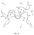
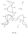
図3及び図4の典型的な実施例に関して説明したように、ジョイント900の作動は、対応するピン間の歯凹部から外されるように、対応するピンから解放される歯をもたらし得る。図11Bは、例えば矢印940の反時計回り方向に沿ったディスク910、920の互いに対する回転によるジョイント900の動作の際のジョイント900を示す。図11B−図11Eで示す可動域は反時計回りのものであるが、当業者は、説明される動きが矢印940の時計回り方向における動きにも適用されることを理解するであろう。このように、図11A及び説明された他の種々の実施例に示された対称形状において、可動域は、リスト構造の長手軸に関するプラス/マイナス(時計回り/半時計回り)の範囲を含む。しかしながら、リストジョイントは、長手軸に対して1方向のみに動くように構成されてもよく、それ故に、ジョイント構造の半分のみ(例えば、図11Aに示す軸901の左側又は右側の何れか)が提供されてもよい。
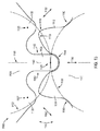
As described with respect to the exemplary embodiment of FIGS. 3 and 4, actuation of joint 900 may result in a tooth being released from the corresponding pin as it is disengaged from the tooth recess between the corresponding pins. FIG. 11B shows the joint 900 during operation of the joint 900 by rotation of the
図11Bに示すように、図示されたように回転するためのジョイント900の作動は、ディスク910、920が互いに対して回転させられるにつれて、ピン926とピン924の間にあるディスク920の凹部982内に歯914が更に及ぶようにさせる。反対に、歯912は、凹部980から引き抜かれてピン922及びピン924から解放され始める。ピン922とピン924の間の凹部980からの歯912の解放は、図11C及び図11Dに示すようにジョイント900が回転し続けるにつれて進行する。図11C及び図11Dは、凹部980から完全に外され、ピン922及びピン924から解放された歯912を示す。図11Eに示すように、ジョイント900がその最大可動域(ロールリミット角)に達するとジョイント900の関節運動は止まる。その時点において、歯912はピン922とピン924の間の凹部から完全に外され、歯914の少なくとも一部(図11の実施例ではその大部分)はピン926とピン924の間の凹部982内に留まり、且つ、ピン926はディスク910の肩部951とかみ合う。肩部951は、ジョイント900の可動域の最も端の位置でジョイント900の関節運動を停止させ且つジョイント900の姿勢を支持することを支援する機械的制止部としての機能を果たす。
As shown in FIG. 11B, the operation of the joint 900 to rotate as shown is within the
図11Aに関して説明したように、ディスク910、920は、ディスク910とディスク920の間の大きな(回転)可動域の実現を容易にするために、切り欠き942、950を含んでいてもよい。しかしながら、切り欠き942、950は、製造が困難な場合がある。特にディスク920が成形プロセスによって製造される場合、特に図5の典型的な実施例におけるように歯912、914とピン922、924、926が負担突起の半径方向内側に位置付けられる場合、ディスク910、920の隣接する構成要素に関する切り欠き942、950の形状が原因で、金型表面で切り欠き942、950を形成しその後に切り欠き942、950から金型表面を引き抜くことが困難なためである。また、図9の典型的な実施例におけるように歯912、914とピン922、924、926が半径方向内側に位置付けられる場合、その内側配置は、歯912、914とピン922、924、926の機械加工を挑戦的なものとする。
As described with respect to FIG. 11A, the
ジョイントディスクの製造し易さを改善するため、ジョイントディスクは、より少ない切り欠きを有する形状、又は、切り欠きのない形状で設計されてもよい。図12を見ると、典型的な実施例にしたがって、歯1012、1014を備えた第1ディスク1010と、ピン1022、1024、1026を備えた第2ディスク1020を含むジョイント1000の側面図が示されている。(破線で表された)円弧1030、1032は、ディスク1010とディスク1020の間の接触面を表す。例えば、円弧1030、1032は、図5及び図9の典型的な実施例に関して説明された円弧930、932と同様に、負担突起540、544、740、744の面の投影であってもよい。それ故に、ディスク1010、1020は、あたかもディスク1010、1020が互いに対して転がる(円弧1030、1032で表される)2つの円としての機能を果たすように、方向1040において互いに対して回転し得る。
In order to improve the manufacturability of the joint disc, the joint disc may be designed with a shape with fewer or no cutouts. Turning to FIG. 12, a side view of a joint 1000 including a
図12の典型的な実施例において、歯1012、1014とピン1022、1024、1026は、図11Aの典型的な実施例のものよりも小さい程度で半径方向1052に沿って延びるように形成されている。結果として、ピン中心1023、1025、1027は、円弧1032からオフセットされている。例えば、図12に示す中立位置では、長手軸1001がディスク1010、1020の双方の中心を通過するように、ジョイント1000は真っ直ぐとなっている。ピン中心1023、1025、1027は、例えば、円弧1032によって表される負担突起よりも小さい程度で(円弧1032の中心に向かう半径方向であってもよい)半径方向1052に沿ってディスク1010の方に延びることによって円弧1032からオフセットされていてもよい。ピン1022、1024、1026の中心1023、1025、1027は、ジョイント1000が関節運動させられたときに円弧1032上に留まっていてもよい。それ故に、ディスク1010、1020が方向1040に互いに対して回転させられたときに、ピン1022、1024、1026の中心1023、1025、1027は、円弧1032上に留まっていてもよい。ピン中心1023、1025、1027と円弧1032の間の距離が実質的に変化しないためである。歯1012、1014とピン1022、1024、1026は半径方向1052に沿ってより小さい程度で延びているため、ステム1043の側部1042は切り欠きがなく実質的に真っ直ぐとなり得る。また、歯1012、1014の横にある位置1050も、図11Aの典型的な実施例における切り欠き950のような切り欠きを欠いていてもよい。それ故に、ディスク1010、1020は、より少ない切り欠きのため、或いは、切り欠きがないため、互いにかみ合う表面に起因するような金型表面の引き抜きを妨げる表面輪郭を最小限に抑え或いは排除することができ、製造がより容易となり得る。
In the exemplary embodiment of FIG. 12,
しかしながら、歯1012、1014とピン1022、1024、1026は、半径方向1052に沿ってより小さい程度で延びるため、歯1012、1014とピン1022、1024、1026は、例えば図11Aの典型的な実施例に比べ、より小さい程度でかみ合い且つ係合する。結果として、ジョイント1000の関節運動は、例えばディスク1010、1020が方向1040において互いに対して回転させられたとき等に、あまり滑らかではないものとなり得る。更に、歯1012、1014とピン1022、1024、1026によってもたらされるタイミングの程度は、図11Aの典型的な実施例におけるような、歯とピンの間のより大きなかみ合いを有するジョイントと比べ、悪化し得る。
However, since the
これらの検討に鑑み、ジョイントの製造し易さと、ジョイントにおける歯とピンの間のかみ合いとのバランスをもたらすジョイントを提供することが望ましいこととなり得る。図13を見ると、歯1112、1114を有する第1ディスク1110と、ピン1122、1124、1126を有する第2ディスク1120を含むジョイント1100の典型的な実施例の側面図が示されている。(破線で表された)円弧1130、1132は、ディスク1110とディスク1120の間の接触面を表す。例えば、円弧1130、1132は、図5及び図9の典型的な実施例に関して説明された円弧930、932と同様に、負担突起540、544、740、744の面の投影であってもよい。それ故に、ディスク1110、1120は、あたかもディスク1110、1120が互いに対して転がる(円弧1130、1132で表される)2つの円としての機能を果たすように、方向1140において互いに対して回転し得る。
In view of these considerations, it may be desirable to provide a joint that provides a balance between the ease of manufacture of the joint and the engagement between the teeth and pins in the joint. Turning to FIG. 13, a side view of an exemplary embodiment of a joint 1100 including a
図13の典型的な実施例では、ピン1122、1126は、ピン1122、1126が円弧1132からオフセットされるべく、半径方向1152に沿ってより小さい程度で延びるように構成される。しかし、ピン1124は、半径方向1152に沿ってピン1122、1126よりも大きく延びる。このため、ピン1122、1126のそれぞれの中心1123、1127は、半径方向1152に沿って円弧1132から半径方向にオフセットされる。しかし、ピン1124の中心1125は、円弧1132上に位置付けられる。図13に示す中立位置では、例えば、長手軸1101がディスク1110、1120の双方の中心を通るように、ジョイント1100は真っ直ぐとなっている。更に、方向1140においてディスク1110、1120が互いに対して回転させられた場合、ピン1124の中心1125は、円弧1132上に留まり得る。ピン中心1123、1125、1127と円弧1132の間の距離が実質的に変化しないためである。また、ピン1124は、歯1112と歯1114の間に位置付けられた凹部1144内に受け入れられるように延びてもよい。結果として、歯1112、1114とピン1122、1124、1126は、図12の典型的な実施例におけるよりも大きい程度で互いにかみ合い且つ係合し、図12の典型的な実施例に比べ、より滑らかな動きと改善されたタイミングをもたらし得る。また、ステム1143の側部1142は、切り下げを欠いていてもよい。ピン1124はステム1143から延びる。また、歯1112、1114の横にある位置1150も切り下げを欠いていてもよい。ディスク1110、1120の製造を容易にするためである。このように、ジョイント1100における対の一方のディスク1120と対の他方のディスク1110との間の接触面を表す円弧1132から軸方向にオフセットされている少なくとも1つのピンと、円弧1132からオフセットされていない少なくとも1つのピンとを含むディスク1120を提供することによって、製造の容易さと、歯とピンの間のかみ合いとのバランスがもたらされ得る。そして、ジョイントの動きとジョイントの“タイミング”の滑らかさに影響を与える。図13の典型的な実施例では、ピン1124は円弧1132からオフセットされておらず、ピン1122、1126は円弧1132からオフセットされているが、他の構成が用いられてもよい。例えば、4つのピンを含むディスクは、ディスクの接触面を表す円弧からオフセットされた2つの端部ピンを有し、一方で、中央の2つのピンは、その円弧からオフセットされていなくてもよい。
In the exemplary embodiment of FIG. 13, pins 1122, 1126 are configured to extend to a lesser extent along
例えば図11A−図11Eのジョイントの動きに関して説明したように、図12及び図13の典型的な実施例における歯も、ジョイント1000、1100の関節運動の際に、ディスクの回転方向に応じて、凹部のそれぞれから外され/引き抜かれることが理解されるべきである。更に、図11B−図11Eに関して説明したように、ジョイント1000、1100の歯は、ジョイント1000、1100の関節運動の際に、対応するピンとの係合から解放されてもよい。図11Aから図11Eの一連の図は、位置合わせされた(ゼロ角の)幾何学的配置から一例としての約90度のロールリミット角まで2つのディスクが回転するときの、接触負担面とその接触負担面に隣接するタイミング構造を含む2つのディスクの間のロール運動を示す。2つの負担面は互いに対して転がるので、ロール角リミット制止部として機能すべく、ピン926の側部が肩部951に引っ掛かり且つ歯914の外面がピン924の外面に引っ掛かるまで、歯の外面と対応凹部の外面は互いにスライドする。引っ掛かっているこれらのロール角リミット制止部の何れか1つは、実施例によっては排除されてもよく、別の機械的ロール角リミット制止部が用いられる他の実施例ではそれらの双方が排除されてもよい。更に別の実施例では、機械的ロール角リミット制止部が用いられず、2つのディスクの間の角度関係は、予期された荷重の下でジョイントの係合を解除させ得る定められた角度をその角度が超えないように制御される。
For example, as described with respect to the joint movement of FIGS. 11A-11E, the teeth in the exemplary embodiment of FIGS. 12 and 13 also depend on the rotational direction of the disk during articulation of the
また、図11A−図13の典型的な実施例におけるジョイント900、1000、1100は、図5及び図9の典型的な実施例で説明されたような、圧縮荷重を受けるための負担突起(図示せず。)を含んでいてもよい。上述のように、負担突起は、円弧930、932、1030、1032、1130、1132によって表される面を提供してもよい。それらの負担突起は、ジョイント900、1000、1100の歯とピンが互いに間隔を空けられたままとなるのを可能にし得る。例えば、図12の典型的な実施例におけるジョイント1000に含まれる負担突起は、図12の典型的な実施例で示されたように、通常の状況の際(例えば横力及び/又はトルクがジョイント1000に適用されていない場合)に、歯1012、1014とピン1022、1024、1026が互いに間隔を空けて配置されるのを可能にし得る。或いは、図11A−図13の典型的な実施例におけるジョイントは、ジョイントの歯とピンが圧縮荷重を受けることで、負担突起を欠いていてもよい。特に、図11Aのジョイント900は、ジョイント900の歯912、914とピン922、924、926で圧縮荷重を受けるため、また、図13のジョイント1100は、図13の典型的な実施例に示す姿勢をディスク1110、1120がとる場合にジョイント1100のピン1124と共に、凹部1144と歯1112、1114で圧縮荷重を受けるため、突起を欠いていてもよい。
Also, the
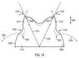
1又は複数のピンが円弧からオフセットされる構成を利用することで、ピンと歯の形状は変更され得る。例えば、歯1112、1114は、(ピン中心923、925、927が円弧932上にある)図11Aの典型的な実施例における歯912、914よりも非対称となるように形成されてもよく、歯1112の第1側部1113は、歯1112の第2側部1115とは異なる曲率を辿ってもよい。非対称に形成された歯は、切り欠きの低減又は排除と同様に、歯とピンとの間のかみ合いに影響を与え得る。図14を見ると、ディスク1210の典型的な実施例が示されている。線1220は、図12の典型的な実施例におけるように、対応するピン(図示せず。)が円弧からオフセットされているときの歯1212、1214の形状の外形を描く。対照的に、線1230は、図11Aの典型的な実施例におけるように、対応するピン(図示せず。)が円弧からオフセットされていないときの歯1212、1214の形状を表す。図13の典型的な実施例におけるように、いくつかのピンがオフセットされ且ついくつかのピンがオフセットされていない場合、歯1212、1214は、線1220と線1230の合成(hybrid)である形状を有していてもよい。線1233、1235は、図14に示すように、歯1212、1214の長手軸であってもよく、また、歯1212、1214の先端1234を通って延びてもよい。線1220と線1230との比較は、線1230が、線1220よりも、歯1212、1214に関して対称的な形状をもたらすことを示す。更に、線1220は、低減或いは排除されなければ横位置1222に位置付けられていたであろう(線1230で示される)切り欠き1232を低減させ或いは排除している。また、線1220は、線1230によってもたらされる歯の先端1234に比べ、歯の先端1224が方向1250に沿って延びる大きさの低減をもたらし得る。
By utilizing a configuration in which one or more pins are offset from the arc, the shape of the pins and teeth can be changed. For example,
本書で説明された典型的な実施例及び方法は、遠隔操作手術システムための手術器具又は他の器具で用いられるものとして説明された。しかしながら、本書で説明された典型的な実施例及び方法は、関節運動を用いる腹腔鏡器具及び他の手持ち式器具のような他のタイプの装置で用いられてもよい。 The exemplary embodiments and methods described herein have been described for use with surgical instruments or other instruments for teleoperated surgical systems. However, the exemplary embodiments and methods described herein may be used with other types of devices, such as laparoscopic instruments using articulation and other handheld instruments.
本書の開示内容を考慮することで更なる変形例及び代替の実施例が当業者にとって明白となるであろう。例えば、それらのシステム及び方法は、動作を明確にするために図及び説明文から省略された追加的な構成要素又はステップを含んでいてもよい。したがって、ここでの記載は、単なる説明的なものとして解釈されるべきであり、本教示を実行する際の一般的な方法を当業者に教示することを目的とするものである。本書で示され且つ説明された種々の実施例は、例示的なものとして解釈されるべきであることが理解されるべきである。要素及び物質、並びに、それらの要素及び物質の配置は、本書で図示され且つ説明されたものの代わりのものが用いられてもよく、部品及び処理は反転されてもよく、また、本教示のある特徴は独立して用いられてもよく、全てが本書の説明の助けを借りた後で当業者にとって明白となるであろう。本教示及び請求項の精神及び範囲から逸脱することなく、本書で説明された要素に変更が加えられてもよい。 Further variations and alternative embodiments will be apparent to those skilled in the art from consideration of the disclosure herein. For example, the systems and methods may include additional components or steps that are omitted from the figures and legends for clarity of operation. Accordingly, this description is to be construed as illustrative only and is for the purpose of teaching those skilled in the art the general manner of carrying out the present teachings. It should be understood that the various embodiments shown and described herein are to be construed as illustrative. Elements and materials, and arrangements of those elements and materials may be used in place of those shown and described herein, parts and processes may be reversed, and the present teachings The features may be used independently and will all become apparent to those skilled in the art after the aid of the description in this document. Changes may be made in the elements described herein without departing from the spirit and scope of the present teachings and claims.
本書で説明された特定の例及び実施例は非限定的であり、本教示の範囲から逸脱することなく、構造、寸法、材料、及び方法に対する改良が行われてもよいことは理解されるべきである。 It should be understood that the specific examples and embodiments described herein are non-limiting and that modifications to the structure, dimensions, materials, and methods may be made without departing from the scope of the present teachings. It is.
本開示にしたがった他の実施例は、明細書の検討及び本書で開示された発明の実施から当業者にとって明白となるであろう。明細書及び例は単なる説明として検討され、真の範囲及び精神が請求項によって示されることが意図されている。 Other embodiments in accordance with the present disclosure will be apparent to those skilled in the art from consideration of the specification and practice of the invention disclosed herein. It is intended that the specification and examples be considered as exemplary only, with a true scope and spirit being indicated by the claims.
Claims (40)
第1ディスク;
前記第1ディスクに隣接する第2ディスク;及び
前記第1ディスク及び前記第2ディスクを通って延びる駆動テンドンであり、
前記第1ディスク及び前記第2ディスクのそれぞれが互いにかみ合う対向するジョイント特徴を含み、
前記第1ディスク及び前記第2ディスクが前記ジョイント特徴とは別の対向する荷重負担面を含む、駆動テンドン;を含み、
前記駆動テンドンは、前記第1ディスクと前記第2ディスクとの間の相対回転をもたらすために、前記第1ディスク及び前記第2ディスクの少なくとも一方に力を及ぼすように構成され、
前記第1ディスク及び前記第2ディスクは、互いに関して±45度程度よりも大きい最大回転可動域を有する、
リストジョイント。 Wrist joint:
First disc;
A second disk adjacent to the first disk; and a drive tendon extending through the first disk and the second disk;
Each of the first and second disks includes opposing joint features that engage each other;
A drive tendon, wherein the first disk and the second disk include opposing load bearing surfaces separate from the joint feature;
The drive tendon is configured to exert a force on at least one of the first disk and the second disk to provide relative rotation between the first disk and the second disk;
The first disk and the second disk have a maximum rotational range of motion greater than about ± 45 degrees relative to each other;
Wrist joint.
請求項1のリストジョイント。 The load bearing surface is positioned radially inward of each joint feature in each of the first disk and the second disk.
The wrist joint according to claim 1.
請求項1のリストジョイント。 The load bearing surface is positioned radially outward of each joint feature in each of the first disk and the second disk.
The wrist joint according to claim 1.
請求項1のリストジョイント。 The joint feature of one of the first disc and the second disc includes a plurality of teeth, and the joint feature of the other of the first disc and the second disc includes a plurality of pins;
The wrist joint according to claim 1.
請求項4のリストジョイント。 The pin and the tooth have a cycloid-shaped surface,
The wrist joint according to claim 4.
請求項4のリストジョイント。 The other of the first disk and the second disk including the plurality of pins includes a trochoid shape and includes at least one recess configured to receive one of the plurality of teeth;
The wrist joint according to claim 4.
前記投影は、前記複数のピンの平面上への投影である、
請求項4のリストジョイント。 The center of each of the plurality of pins is positioned on an arc that is a projection of the load bearing surface of a disk including the plurality of pins,
The projection is a projection onto a plane of the plurality of pins.
The wrist joint according to claim 4.
前記投影は、前記複数のピンの平面上への投影である、
請求項4のリストジョイント。 The center of each of the plurality of pins is radially offset from an arc that is a projection of the load bearing surface of the disk including the plurality of pins,
The projection is a projection onto a plane of the plurality of pins.
The wrist joint according to claim 4.
前記ピンの少なくとも1つの中心は、前記円弧の上に位置付けられ、
前記投影は、前記複数のピンの平面上への投影である、
請求項4のリストジョイント。 At least one center of the pin is offset from an arc that is a projection of the load bearing surface of the disk including the plurality of pins;
At least one center of the pin is positioned on the arc;
The projection is a projection onto a plane of the plurality of pins.
The wrist joint according to claim 4.
前記投影は、前記複数のピンの平面上への投影である、
請求項4のリストジョイント。 The centers of the plurality of pins are radially offset by different distances from an arc that is a projection of the load bearing surface of a disk including the plurality of pins,
The projection is a projection onto a plane of the plurality of pins.
The wrist joint according to claim 4.
請求項4のリストジョイント。 The pin has a constant radius of curvature;
The wrist joint according to claim 4.
請求項4のリストジョイント。 The pins have different diameters,
The wrist joint according to claim 4.
請求項4のリストジョイント。 At least one of the teeth is a separate part from the one of the first disk and the second disk;
The wrist joint according to claim 4.
請求項4のリストジョイント。 At least one of the pins is a part different from the other of the first disk and the second disk.
The wrist joint according to claim 4.
請求項1のリストジョイント。 The load bearing surface has a partial cylindrical shape,
The wrist joint according to claim 1.
請求項1のリストジョイント。 The load bearing surface has a cycloid shape,
The wrist joint according to claim 1.
前記荷重負担面は、前記支柱の上にある、
請求項1のリストジョイント。 Further comprising a support,
The load bearing surface is on the support;
The wrist joint according to claim 1.
請求項1のリストジョイント。 The wrist joint has a diameter of about 3 mm to about 13 mm;
The wrist joint according to claim 1.
請求項1のリストジョイント。 The wrist joint is a two-piece joint.
The wrist joint according to claim 1.
請求項1のリストジョイント。 The joint features of the first disk and the second disk are configured to rotate with respect to each other in a pin gear motion;
The wrist joint according to claim 1.
シャフト;
前記シャフトの第1端に結合されるエンドエフェクタ;
前記第1端の反対にある前記シャフトの第2端に配置される伝達機構であり、前記エンドエフェクタを作動させるために前記伝達機構が作動要素を通じて駆動力を伝達する、伝達機構;及び
前記エンドエフェクタを前記シャフトに結合するリストジョイント;を含み、
前記リストジョイントは、一緒に結合される隣接する一対のディスクを含み、
前記リストジョイントは、±45度より大きい最大可動域を有する、
手術器具。 Surgical instruments:
shaft;
An end effector coupled to the first end of the shaft;
A transmission mechanism disposed at a second end of the shaft opposite the first end, wherein the transmission mechanism transmits a driving force through an actuating element to actuate the end effector; and the end A wrist joint for coupling an effector to the shaft;
The wrist joint includes a pair of adjacent disks coupled together;
The wrist joint has a maximum range of motion greater than ± 45 degrees;
Surgical instruments.
前記ディスクの他方は複数のピンを含み、
前記複数の歯及び前記複数のピンの少なくともいくつかは、関節運動の際に、互いにかみ合う、
請求項21の手術器具。 One of the disks includes a plurality of teeth;
The other of the disks includes a plurality of pins;
At least some of the plurality of teeth and the plurality of pins mesh with each other during articulation;
The surgical instrument of claim 21.
前記荷重負担面は、第1ディスク及び第2ディスクのそれぞれの各ジョイント特徴の半径方向内側に位置付けられる、
請求項21の手術器具。 The disc further includes a joint feature and a load bearing surface,
The load bearing surface is positioned radially inward of each joint feature of each of the first and second disks;
The surgical instrument of claim 21.
前記荷重負担面は、第1ディスク及び第2ディスクのそれぞれの各ジョイント特徴の半径方向外側に位置付けられる、
請求項21の手術器具。 The disc further includes a joint feature and a load bearing surface,
The load bearing surface is positioned radially outward of each joint feature of each of the first disk and the second disk.
The surgical instrument of claim 21.
請求項21の手術器具。 The maximum range of motion is in the range of about ± 75 degrees to about ± 90 degrees.
The surgical instrument of claim 21.
請求項21の手術器具。 The wrist joint is a two-piece joint.
The surgical instrument of claim 21.
請求項21の手術器具。 The transmission mechanism is configured to engage a patient side manipulator of a teleoperated surgical system to receive a driving force to actuate the surgical instrument.
The surgical instrument of claim 21.
シャフト;
前記シャフトの第1端に結合されるエンドエフェクタ;
前記第1端の反対にある前記シャフトの第2端に配置される伝達機構であり、前記エンドエフェクタを作動させるために前記伝達機構が作動要素を通じて駆動力を伝達する、伝達機構;及び
前記エンドエフェクタを前記シャフトに結合する関節運動可能なリスト;を含み、
前記リストは:
複数の歯と、前記複数の歯とは別の第1荷重負担面とを有する第1ディスク;及び
前記歯とかみ合うように構成された複数のピンと、前記複数のピンとは別の第2荷重負担面とを有する第2ディスク;を含み、
前記第1荷重負担面と前記第2荷重負担面とは、前記リストの圧縮力を受けるために互いに係合する、
手術器具。 Surgical instruments:
shaft;
An end effector coupled to the first end of the shaft;
A transmission mechanism disposed at a second end of the shaft opposite the first end, wherein the transmission mechanism transmits a driving force through an actuating element to actuate the end effector; and the end An articulatable list coupling an effector to the shaft;
The list is:
A first disk having a plurality of teeth and a first load bearing surface separate from the plurality of teeth; and a plurality of pins configured to engage with the teeth; and a second load bearing separate from the plurality of pins A second disk having a surface;
The first load bearing surface and the second load bearing surface engage each other to receive the compressive force of the wrist;
Surgical instruments.
前記第2荷重負担面は前記ピンの半径方向内側に位置付けられる、
請求項28の手術器具。 The first load bearing surface is positioned radially inward of the teeth;
The second load bearing surface is positioned radially inward of the pin;
30. The surgical instrument of claim 28.
前記第2荷重負担面は前記ピンの半径方向外側に位置付けられる、
請求項28の手術器具。 The first load bearing surface is positioned radially outward of the teeth;
The second load bearing surface is positioned radially outward of the pin;
30. The surgical instrument of claim 28.
請求項28の手術器具。 All the centers of the pins of the second disk are positioned on an arc that is a projection of the second load bearing surface onto the plane of the pins;
30. The surgical instrument of claim 28.
請求項28の手術器具。 The center of each of the pins of the second disk is offset from an arc that is a projection of the second load bearing surface onto the plane of the pin;
30. The surgical instrument of claim 28.
前記ピンの少なくとも1つの中心は、前記円弧の上に位置付けられる、
請求項28の手術器具。 At least one center of the pin of the second disk is offset from an arc that is a projection of the second load bearing surface onto the plane of the pin;
At least one center of the pin is positioned on the arc;
30. The surgical instrument of claim 28.
前記リストジョイントの第1ディスク及び第2ディスクの少なくとも1つに結合される駆動テンドンに力を適用し、前記第1ディスク及び前記第2ディスクを互いに関して回転させ;
前記第1ディスク及び前記第2ディスクの回転の際に、前記第1ディスク及び前記第2ディスクが互いに関して±45度程度よりも大きく回転させられたときに、前記第1ディスク及び前記第2ディスクの一方における複数の歯の少なくとも1つが、前記第1ディスク及び前記第2ディスクの他方における複数のピンの少なくとも1つとかみ合ったままとなり、且つ、前記第1ディスクの荷重負担面及び前記第2ディスクの荷重負担面が互いに接触したままとなり、
前記第1ディスクの前記荷重負担面及び前記第2ディスクの前記荷重負担面は、前記歯及び前記ピンから半径方向に間隔を空けられている、
方法。 A method of articulating a wrist joint:
Applying a force to a driving tendon coupled to at least one of the first and second disks of the wrist joint, causing the first and second disks to rotate with respect to each other;
When the first disk and the second disk are rotated more than about ± 45 degrees with respect to each other during the rotation of the first disk and the second disk, the first disk and the second disk At least one of the plurality of teeth in one of the first disk and the second disk remains engaged with at least one of the plurality of pins, and the load bearing surface of the first disk and the second disk Load-bearing surfaces of each other remain in contact with each other,
The load bearing surface of the first disk and the load bearing surface of the second disk are spaced radially from the teeth and the pin;
Method.
複数の歯と、前記複数の歯とは別の第1荷重負担面とで第1ディスクを構成し;
複数のピンと、前記複数のピンとは別の第2荷重負担面とで第2ディスクを構成し;
前記第1ディスク及び前記第2ディスクを通って駆動テンドンを延ばし;且つ
第1ジョイント特徴と第2ジョイント特徴とがかみ合い且つ前記第1荷重負担面と前記第2荷重負担面とが互いに接触するように前記第1ディスク及び前記第2ディスクを互いに結合し;
前記第1ディスク及び前記第2ディスクは、互いに関して±45度程度より大きい最大回転可動域を有する、
方法。 A method of manufacturing a wrist joint comprising:
A first disk is composed of a plurality of teeth and a first load bearing surface different from the plurality of teeth;
Forming a second disk with a plurality of pins and a second load bearing surface separate from the plurality of pins;
Extending the drive tendon through the first disk and the second disk; and the first joint feature and the second joint feature are engaged, and the first load bearing surface and the second load bearing surface are in contact with each other. Connecting the first disk and the second disk to each other;
The first disk and the second disk have a maximum range of rotation greater than about ± 45 degrees relative to each other;
Method.
第1ギアインタフェースと第1円筒負担面を含む第1リスト構成要素であり、前記第1ギアインタフェースが第1歯及び第2歯を含む、第1リスト構成要素;
前記第1リスト構成要素に可動的に結合される第2リスト構成要素であり、
前記第1歯及び前記第2歯とそれぞれかみ合うように構成された第1凹面及び第2凹面を含む第2ギアインタフェースと、
前記第1円筒負担面によって支持される第2円筒負担面と、
を含む第2リスト構成要素;を含み、
前記第2リスト構成要素は、45度より大きい角度可動域を通じて、前記第1リスト構成要素に関して可動であり、その際に、前記第2ギアインタフェースと前記第1ギアインタフェースとがかみ合い、且つ、前記第2円筒負担面が前記第1円筒負担面に沿って転がり、
前記第1歯の一部の少なくとも1つが前記第1凹面内に受け入れられ且つ前記第1凹面に関して動き、且つ、前記第2歯の一部の少なくとも1つが前記第2凹面に受け入れられ且つ前記第2凹面に関して動くように、前記第1ギアインタフェースと前記第2ギアインタフェースとがかみ合う、
医療機器。 Medical device:
A first list component including a first gear interface and a first cylindrical bearing surface, wherein the first gear interface includes a first tooth and a second tooth;
A second list component movably coupled to the first list component;
A second gear interface including a first concave surface and a second concave surface configured to mesh with the first tooth and the second tooth, respectively;
A second cylindrical bearing surface supported by the first cylindrical bearing surface;
A second list component comprising:
The second wrist component is movable with respect to the first wrist component through an angular range of motion greater than 45 degrees, wherein the second gear interface and the first gear interface are engaged, and the A second cylindrical bearing surface rolls along the first cylindrical bearing surface;
At least one portion of the first tooth is received in the first concave surface and moves with respect to the first concave surface, and at least one portion of the second tooth is received in the second concave surface and the first The first gear interface and the second gear interface mesh to move with respect to two concave surfaces;
Medical equipment.
第1負担面と第1タイミング特徴とを含む第1リスト構成要素であり、
前記第1タイミング特徴が前記第1負担面に隣接し、
前記第1タイミング特徴が第1側歯、第2側歯、及び、前記第1側歯と前記第2側歯との間の中央凹部を含み、
前記第1側歯は外面を有し、
前記第2側歯は外面を有する、第1リスト構成要素;並びに
第2負担面と第2タイミング特徴とを含む第2リスト構成要素であり、
前記第2タイミング特徴が前記第2負担面に隣接し、
前記第2タイミング特徴が、第1側部と反対側の第2側部とを有する中央ピン、前記中央ピンの前記第1側部に隣接する第1側凹部、及び、前記中央ピンの前記第2側部に隣接する第2側凹部を含む、第2リスト構成要素;を含み、
前記第1負担面と前記第2負担面とは転がり接触し、
前記第1リスト構成要素と前記第2リスト構成要素との間のゼロ角ロールアライメントから遠ざかる第1回転可動域で前記第2負担面に対して前記第1負担面が転がるときに、前記第1側歯の前記外面が前記第1側凹部の表面に沿って滑り接触し、且つ、前記第2側歯が前記第2側凹部から引き抜かれ、
前記第1リスト構成要素と前記第2リスト構成要素との間の前記ゼロ角ロールアライメントから遠ざかる第2回転可動域で前記第2負担面に対して前記第1負担面が転がるときに、前記第2側歯の前記外面が前記第2側凹部の表面に沿って滑り接触し、且つ、前記第1側歯が前記第1側凹部から引き抜かれ、
前記第2回転可動域は、前記第1回転可動域の反対の方向にある、
医療機器。 Medical device:
A first list component including a first burden surface and a first timing feature;
The first timing feature is adjacent to the first bearing surface;
The first timing feature includes a first side tooth, a second side tooth, and a central recess between the first side tooth and the second side tooth;
The first side teeth have outer surfaces;
The second side tooth has an outer surface, a first list component; and a second list component including a second bearing surface and a second timing feature;
The second timing feature is adjacent to the second bearing surface;
The second timing feature includes a center pin having a first side and a second side opposite the first side, a first side recess adjacent to the first side of the center pin, and the first of the center pin. A second wrist component including a second side recess adjacent to the two sides;
The first load surface and the second load surface are in rolling contact,
When the first load surface rolls relative to the second load surface in a first range of rotation away from zero angle roll alignment between the first list component and the second list component, the first The outer surfaces of the side teeth are slidingly contacted along the surface of the first side recess, and the second side teeth are pulled out from the second side recess;
When the first load surface rolls with respect to the second load surface in a second rotation movable range away from the zero angle roll alignment between the first list component and the second list component, The outer surface of the two-side teeth is in sliding contact along the surface of the second-side recess, and the first-side teeth are extracted from the first-side recess;
The second rotation movable range is in a direction opposite to the first rotation movable range;
Medical equipment.
請求項37の医療機器。 The outer surface of the first side tooth is engaged with the first side portion of the central pin at a roll limit angle of the first rotation movable range.
38. The medical device of claim 37.
前記第2タイミング特徴は、前記中央ピンの向かい側にある前記第1側凹部に隣接する第1側ピンを含み、
前記第1リスト構成要素と前記第2リスト構成要素との間の前記ゼロ角ロールアライメントのところで、前記中央ピンは前記中央凹部内にあり、且つ、前記第1側ピンは前記第1側凹部の外にあり、
前記第1回転可動域のロールリミット角のところで、前記中央ピンは前記中央凹部の外にあり、且つ、前記第1側ピンは前記第1側凹部内にある、
請求項37の医療機器。 The first timing feature includes a first side recess adjacent to the first side tooth opposite the central recess;
The second timing feature includes a first side pin adjacent to the first side recess opposite the central pin;
At the zero angle roll alignment between the first list component and the second list component, the center pin is in the center recess, and the first side pin is in the first side recess. Outside,
At the roll limit angle of the first rotation movable range, the center pin is outside the center recess, and the first side pin is in the first recess.
38. The medical device of claim 37.
請求項37の医療機器。 The roll limit angle of the range of rotation is greater than ± 45 degrees.
38. The medical device of claim 37.
Priority Applications (1)
| Application Number | Priority Date | Filing Date | Title |
|---|---|---|---|
| JP2020000167A JP6961733B2 (en) | 2014-02-21 | 2020-01-06 | Mechanical wrist joints, related devices, and methods with improved range of motion |
Applications Claiming Priority (3)
| Application Number | Priority Date | Filing Date | Title |
|---|---|---|---|
| US201461943068P | 2014-02-21 | 2014-02-21 | |
| US61/943,068 | 2014-02-21 | ||
| PCT/US2015/016879 WO2015127250A1 (en) | 2014-02-21 | 2015-02-20 | Mechanical wrist joints with enhanced range of motion, and related devices and methods |
Related Child Applications (1)
| Application Number | Title | Priority Date | Filing Date |
|---|---|---|---|
| JP2020000167A Division JP6961733B2 (en) | 2014-02-21 | 2020-01-06 | Mechanical wrist joints, related devices, and methods with improved range of motion |
Publications (2)
| Publication Number | Publication Date |
|---|---|
| JP2017513720A true JP2017513720A (en) | 2017-06-01 |
| JP2017513720A5 JP2017513720A5 (en) | 2018-03-29 |
Family
ID=53879043
Family Applications (3)
| Application Number | Title | Priority Date | Filing Date |
|---|---|---|---|
| JP2016552999A Pending JP2017513720A (en) | 2014-02-21 | 2015-02-20 | Mechanical wrist joint with improved range of motion, associated apparatus and method |
| JP2020000167A Active JP6961733B2 (en) | 2014-02-21 | 2020-01-06 | Mechanical wrist joints, related devices, and methods with improved range of motion |
| JP2021168142A Pending JP2022002759A (en) | 2014-02-21 | 2021-10-13 | Mechanical wrist joint with improved movable range, and related devices and methods |
Family Applications After (2)
| Application Number | Title | Priority Date | Filing Date |
|---|---|---|---|
| JP2020000167A Active JP6961733B2 (en) | 2014-02-21 | 2020-01-06 | Mechanical wrist joints, related devices, and methods with improved range of motion |
| JP2021168142A Pending JP2022002759A (en) | 2014-02-21 | 2021-10-13 | Mechanical wrist joint with improved movable range, and related devices and methods |
Country Status (6)
| Country | Link |
|---|---|
| US (3) | US10639805B2 (en) |
| EP (2) | EP4059461A1 (en) |
| JP (3) | JP2017513720A (en) |
| KR (2) | KR102366672B1 (en) |
| CN (2) | CN106061425B (en) |
| WO (1) | WO2015127250A1 (en) |
Cited By (1)
| Publication number | Priority date | Publication date | Assignee | Title |
|---|---|---|---|---|
| US11518048B2 (en) | 2014-02-21 | 2022-12-06 | Intuitive Surgical Operations, Inc. | Mechanical wrist joints with enhanced range of motion, and related devices and methods |
Families Citing this family (33)
| Publication number | Priority date | Publication date | Assignee | Title |
|---|---|---|---|---|
| CN106028995B (en) | 2014-02-21 | 2020-06-30 | 直观外科手术操作公司 | Mechanical joints and related systems and methods |
| US11357483B2 (en) | 2014-09-26 | 2022-06-14 | Intuitive Surgical Operations, Inc. | Surgical instrument with flexible shaft and actuation element guide |
| DE102014221456A1 (en) * | 2014-10-22 | 2016-04-28 | Zf Friedrichshafen Ag | Gear pairing of a gearbox |
| ITUB20154977A1 (en) | 2015-10-16 | 2017-04-16 | Medical Microinstruments S R L | Medical instrument and method of manufacture of said medical instrument |
| ITUB20155057A1 (en) * | 2015-10-16 | 2017-04-16 | Medical Microinstruments S R L | Robotic surgery set |
| US20210106393A1 (en) * | 2015-10-16 | 2021-04-15 | Medical Microinstruments S.p.A. | Surgical tool for robotic surgery and robotic surgical assembly |
| BR112018009251A2 (en) * | 2016-02-05 | 2019-04-09 | Board Of Regents Of The University Of Texas System | surgical apparatus and customized main controller for a surgical apparatus |
| WO2017136729A1 (en) | 2016-02-05 | 2017-08-10 | Board Of Regents Of The University Of Texas System | Steerable intra-luminal medical device |
| JP6989594B2 (en) | 2016-09-09 | 2022-01-05 | インテュイティブ サージカル オペレーションズ, インコーポレイテッド | Wrist structure |
| KR20240052889A (en) | 2016-09-09 | 2024-04-23 | 인튜어티브 서지컬 오퍼레이션즈 인코포레이티드 | Stapler beam architecture |
| WO2018216204A1 (en) * | 2017-05-26 | 2018-11-29 | オリンパス株式会社 | Master-slave manipulator and method for controlling same |
| CN111356413B (en) | 2017-12-14 | 2024-04-12 | 直观外科手术操作公司 | Medical tool with tension band |
| US11439376B2 (en) | 2018-03-07 | 2022-09-13 | Intuitive Surgical Operations, Inc. | Low-friction, small profile medical tools having easy-to-assemble components |
| US11992286B2 (en) | 2018-03-07 | 2024-05-28 | Intuitive Surgical Operations, Inc. | Low-friction medical tools having roller-assisted tension members |
| CN111970985A (en) | 2018-03-07 | 2020-11-20 | 直观外科手术操作公司 | Low friction small medical tool with easily assembled components |
| CN109199592A (en) * | 2018-11-07 | 2019-01-15 | 哈尔滨理工大学 | A kind of micro-wound operation robot of high flexibility |
| EP3870075A4 (en) | 2018-12-20 | 2022-08-03 | Auris Health, Inc. | Shielding for wristed instruments |
| KR102159813B1 (en) * | 2018-12-27 | 2020-09-24 | 재단법인대구경북과학기술원 | Compliant joint |
| US11607217B2 (en) | 2018-12-31 | 2023-03-21 | Cilag Gmbh International | Surgical stapler shaft formed of segments of different materials |
| DE102019103493A1 (en) | 2019-02-12 | 2020-08-13 | Karl Storz Se & Co. Kg | Medical instrument |
| KR102245962B1 (en) | 2019-05-15 | 2021-04-29 | 한국과학기술연구원 | Articulating structure using rolling joint and projection member, and Tube insert device haivng the same |
| US20210177500A1 (en) | 2019-12-12 | 2021-06-17 | Intuitive Surgical Operations, Inc. | Surgical instruments having non-linear cam slots |
| CN111012504B (en) * | 2019-12-23 | 2023-09-15 | 山东中科先进技术有限公司 | Rope-driven joint decoupling mechanism |
| KR102237568B1 (en) | 2019-12-26 | 2021-04-06 | 한양대학교 에리카산학협력단 | Roll Joint |
| CN115426966A (en) | 2020-02-13 | 2022-12-02 | 直观外科手术操作公司 | Apparatus and method for coupling a cable to a medical device |
| US20230172680A1 (en) | 2020-05-04 | 2023-06-08 | Intuitive Surgical Operations, Inc. | Medical instrument having single input for driving multiple cables |
| CN112809732B (en) * | 2021-01-28 | 2022-03-11 | 清华大学 | Rigid-flexible coupling joint based on complex rolling contact curved surface |
| DE202021000992U1 (en) | 2021-03-05 | 2021-06-21 | lNTUITIVE SURGICAL OPERATIONS,INC. | Electrosurgical instruments for sealing and dissection |
| WO2023022913A1 (en) | 2021-08-17 | 2023-02-23 | Intuitive Surgical Operations, Inc. | Surgical instrument cable control and routing structures |
| CN117835925A (en) | 2021-08-18 | 2024-04-05 | 直观外科手术操作公司 | Surgical instrument cutter |
| CN114271938A (en) * | 2021-12-29 | 2022-04-05 | 深圳市罗伯医疗科技有限公司 | Flexible mechanical arm |
| WO2023177565A1 (en) | 2022-03-15 | 2023-09-21 | Intuitive Surgical Operations, Inc. | Medical device wrist |
| CN117072631B (en) * | 2023-10-16 | 2024-01-12 | 深圳康诺思腾科技有限公司 | Fluted disc pair and surgical instrument |
Citations (2)
| Publication number | Priority date | Publication date | Assignee | Title |
|---|---|---|---|---|
| JP2013514861A (en) * | 2009-12-22 | 2013-05-02 | インテュイティブ サージカル オペレーションズ, インコーポレイテッド | Equipment wrist with cycloid surface |
| WO2014016337A1 (en) * | 2012-07-24 | 2014-01-30 | Richard Wolf Gmbh | Shaft for medical instruments, comprising movable sections |
Family Cites Families (10)
| Publication number | Priority date | Publication date | Assignee | Title |
|---|---|---|---|---|
| EP0677276B1 (en) | 1994-04-15 | 2000-06-14 | Smith & Nephew, Inc. | Curved surgical instrument with segmented inner member |
| US6817974B2 (en) | 2001-06-29 | 2004-11-16 | Intuitive Surgical, Inc. | Surgical tool having positively positionable tendon-actuated multi-disk wrist joint |
| US7090637B2 (en) | 2003-05-23 | 2006-08-15 | Novare Surgical Systems, Inc. | Articulating mechanism for remote manipulation of a surgical or diagnostic tool |
| US7828808B2 (en) | 2004-06-07 | 2010-11-09 | Novare Surgical Systems, Inc. | Link systems and articulation mechanisms for remote manipulation of surgical or diagnostic tools |
| KR101016102B1 (en) * | 2008-05-30 | 2011-02-17 | 정창욱 | Tool for Minimally Invasive Surgery |
| US9259275B2 (en) * | 2009-11-13 | 2016-02-16 | Intuitive Surgical Operations, Inc. | Wrist articulation by linked tension members |
| US9339341B2 (en) | 2010-02-08 | 2016-05-17 | Intuitive Surgical Operations, Inc. | Direct pull surgical gripper |
| KR101405087B1 (en) | 2012-04-27 | 2014-06-10 | 한양대학교 에리카산학협력단 | An articulation for surgical instrument |
| KR102046373B1 (en) * | 2013-03-11 | 2019-11-20 | 삼성전자주식회사 | Laparoscopic surgery device having wire reducer |
| CN106061425B (en) | 2014-02-21 | 2020-07-24 | 直观外科手术操作公司 | Mechanical wrist joints with enhanced range of motion and related devices and methods |
-
2015
- 2015-02-20 CN CN201580009730.0A patent/CN106061425B/en active Active
- 2015-02-20 US US15/119,192 patent/US10639805B2/en active Active
- 2015-02-20 WO PCT/US2015/016879 patent/WO2015127250A1/en active Application Filing
- 2015-02-20 CN CN202010595737.8A patent/CN111938812A/en active Pending
- 2015-02-20 KR KR1020167024391A patent/KR102366672B1/en active IP Right Grant
- 2015-02-20 EP EP22171814.1A patent/EP4059461A1/en active Pending
- 2015-02-20 KR KR1020227005573A patent/KR102499270B1/en active IP Right Grant
- 2015-02-20 EP EP15752516.3A patent/EP3107697B1/en active Active
- 2015-02-20 JP JP2016552999A patent/JP2017513720A/en active Pending
-
2020
- 2020-01-06 JP JP2020000167A patent/JP6961733B2/en active Active
- 2020-03-30 US US16/834,447 patent/US11518048B2/en active Active
-
2021
- 2021-10-13 JP JP2021168142A patent/JP2022002759A/en active Pending
-
2022
- 2022-11-11 US US18/054,692 patent/US20230173692A1/en active Pending
Patent Citations (2)
| Publication number | Priority date | Publication date | Assignee | Title |
|---|---|---|---|---|
| JP2013514861A (en) * | 2009-12-22 | 2013-05-02 | インテュイティブ サージカル オペレーションズ, インコーポレイテッド | Equipment wrist with cycloid surface |
| WO2014016337A1 (en) * | 2012-07-24 | 2014-01-30 | Richard Wolf Gmbh | Shaft for medical instruments, comprising movable sections |
Cited By (1)
| Publication number | Priority date | Publication date | Assignee | Title |
|---|---|---|---|---|
| US11518048B2 (en) | 2014-02-21 | 2022-12-06 | Intuitive Surgical Operations, Inc. | Mechanical wrist joints with enhanced range of motion, and related devices and methods |
Also Published As
| Publication number | Publication date |
|---|---|
| CN111938812A (en) | 2020-11-17 |
| US11518048B2 (en) | 2022-12-06 |
| CN106061425B (en) | 2020-07-24 |
| EP3107697B1 (en) | 2022-05-11 |
| WO2015127250A1 (en) | 2015-08-27 |
| EP3107697A1 (en) | 2016-12-28 |
| US10639805B2 (en) | 2020-05-05 |
| JP6961733B2 (en) | 2021-11-05 |
| KR102499270B1 (en) | 2023-02-13 |
| KR20160124789A (en) | 2016-10-28 |
| US20200290215A1 (en) | 2020-09-17 |
| CN106061425A (en) | 2016-10-26 |
| US20230173692A1 (en) | 2023-06-08 |
| JP2020078867A (en) | 2020-05-28 |
| JP2022002759A (en) | 2022-01-11 |
| EP3107697A4 (en) | 2017-11-22 |
| KR20220029754A (en) | 2022-03-08 |
| US20170120457A1 (en) | 2017-05-04 |
| KR102366672B1 (en) | 2022-02-23 |
| EP4059461A1 (en) | 2022-09-21 |
Similar Documents
| Publication | Publication Date | Title |
|---|---|---|
| JP6961733B2 (en) | Mechanical wrist joints, related devices, and methods with improved range of motion | |
| US11944398B2 (en) | Surgical instrument actuation mechanisms | |
| JP6563053B2 (en) | Surgical tool with a small list | |
| US20190298464A1 (en) | Teleoperated surgical instruments | |
| KR102077004B1 (en) | End effector with redundant closing mechanisms | |
| EP1408846B1 (en) | Platform link wrist mechanism | |
| Arkenbout et al. | A state of the art review and categorization of multi-branched instruments for NOTES and SILS | |
| US20210077213A1 (en) | Teleoperated surgical instruments | |
| CN108371550B (en) | Surgical fastener device with geometric tube | |
| US11896334B2 (en) | Computer-assisted teleoperated surgery systems and methods | |
| Francis et al. | Concentric tube instrument for the Da vinci platform | |
| US20220346890A1 (en) | Selectable jaw closure of a robotic surgical system | |
| Chin et al. | Articulated mechanism design and kinematics for natural orifice translumenal endoscopic surgery robot |
Legal Events
| Date | Code | Title | Description |
|---|---|---|---|
| A521 | Request for written amendment filed |
Free format text: JAPANESE INTERMEDIATE CODE: A523 Effective date: 20180214 |
|
| A621 | Written request for application examination |
Free format text: JAPANESE INTERMEDIATE CODE: A621 Effective date: 20180214 |
|
| A131 | Notification of reasons for refusal |
Free format text: JAPANESE INTERMEDIATE CODE: A131 Effective date: 20190205 |
|
| A601 | Written request for extension of time |
Free format text: JAPANESE INTERMEDIATE CODE: A601 Effective date: 20190507 |
|
| A521 | Request for written amendment filed |
Free format text: JAPANESE INTERMEDIATE CODE: A523 Effective date: 20190517 |
|
| A02 | Decision of refusal |
Free format text: JAPANESE INTERMEDIATE CODE: A02 Effective date: 20190903 |