JP2017511633A - Handheld electronic device having a rough surface - Google Patents
Handheld electronic device having a rough surface Download PDFInfo
- Publication number
- JP2017511633A JP2017511633A JP2016554889A JP2016554889A JP2017511633A JP 2017511633 A JP2017511633 A JP 2017511633A JP 2016554889 A JP2016554889 A JP 2016554889A JP 2016554889 A JP2016554889 A JP 2016554889A JP 2017511633 A JP2017511633 A JP 2017511633A
- Authority
- JP
- Japan
- Prior art keywords
- electronic device
- handheld electronic
- recess
- surface structure
- gripping surface
- Prior art date
- Legal status (The legal status is an assumption and is not a legal conclusion. Google has not performed a legal analysis and makes no representation as to the accuracy of the status listed.)
- Pending
Links
Images


Classifications
-
- H—ELECTRICITY
- H04—ELECTRIC COMMUNICATION TECHNIQUE
- H04M—TELEPHONIC COMMUNICATION
- H04M1/00—Substation equipment, e.g. for use by subscribers
- H04M1/02—Constructional features of telephone sets
- H04M1/0202—Portable telephone sets, e.g. cordless phones, mobile phones or bar type handsets
-
- G—PHYSICS
- G03—PHOTOGRAPHY; CINEMATOGRAPHY; ANALOGOUS TECHNIQUES USING WAVES OTHER THAN OPTICAL WAVES; ELECTROGRAPHY; HOLOGRAPHY
- G03B—APPARATUS OR ARRANGEMENTS FOR TAKING PHOTOGRAPHS OR FOR PROJECTING OR VIEWING THEM; APPARATUS OR ARRANGEMENTS EMPLOYING ANALOGOUS TECHNIQUES USING WAVES OTHER THAN OPTICAL WAVES; ACCESSORIES THEREFOR
- G03B15/00—Special procedures for taking photographs; Apparatus therefor
- G03B15/02—Illuminating scene
- G03B15/03—Combinations of cameras with lighting apparatus; Flash units
-
- G—PHYSICS
- G06—COMPUTING; CALCULATING OR COUNTING
- G06F—ELECTRIC DIGITAL DATA PROCESSING
- G06F1/00—Details not covered by groups G06F3/00 - G06F13/00 and G06F21/00
- G06F1/16—Constructional details or arrangements
- G06F1/1613—Constructional details or arrangements for portable computers
- G06F1/1626—Constructional details or arrangements for portable computers with a single-body enclosure integrating a flat display, e.g. Personal Digital Assistants [PDAs]
-
- G—PHYSICS
- G06—COMPUTING; CALCULATING OR COUNTING
- G06F—ELECTRIC DIGITAL DATA PROCESSING
- G06F1/00—Details not covered by groups G06F3/00 - G06F13/00 and G06F21/00
- G06F1/16—Constructional details or arrangements
- G06F1/1613—Constructional details or arrangements for portable computers
- G06F1/1633—Constructional details or arrangements of portable computers not specific to the type of enclosures covered by groups G06F1/1615 - G06F1/1626
- G06F1/1684—Constructional details or arrangements related to integrated I/O peripherals not covered by groups G06F1/1635 - G06F1/1675
- G06F1/1686—Constructional details or arrangements related to integrated I/O peripherals not covered by groups G06F1/1635 - G06F1/1675 the I/O peripheral being an integrated camera
-
- H—ELECTRICITY
- H04—ELECTRIC COMMUNICATION TECHNIQUE
- H04B—TRANSMISSION
- H04B1/00—Details of transmission systems, not covered by a single one of groups H04B3/00 - H04B13/00; Details of transmission systems not characterised by the medium used for transmission
- H04B1/38—Transceivers, i.e. devices in which transmitter and receiver form a structural unit and in which at least one part is used for functions of transmitting and receiving
- H04B1/3827—Portable transceivers
- H04B1/3888—Arrangements for carrying or protecting transceivers
-
- H—ELECTRICITY
- H04—ELECTRIC COMMUNICATION TECHNIQUE
- H04M—TELEPHONIC COMMUNICATION
- H04M1/00—Substation equipment, e.g. for use by subscribers
- H04M1/02—Constructional features of telephone sets
- H04M1/0202—Portable telephone sets, e.g. cordless phones, mobile phones or bar type handsets
- H04M1/026—Details of the structure or mounting of specific components
- H04M1/0264—Details of the structure or mounting of specific components for a camera module assembly
-
- H—ELECTRICITY
- H04—ELECTRIC COMMUNICATION TECHNIQUE
- H04M—TELEPHONIC COMMUNICATION
- H04M1/00—Substation equipment, e.g. for use by subscribers
- H04M1/02—Constructional features of telephone sets
- H04M1/0202—Portable telephone sets, e.g. cordless phones, mobile phones or bar type handsets
- H04M1/0279—Improving the user comfort or ergonomics
-
- G—PHYSICS
- G03—PHOTOGRAPHY; CINEMATOGRAPHY; ANALOGOUS TECHNIQUES USING WAVES OTHER THAN OPTICAL WAVES; ELECTROGRAPHY; HOLOGRAPHY
- G03B—APPARATUS OR ARRANGEMENTS FOR TAKING PHOTOGRAPHS OR FOR PROJECTING OR VIEWING THEM; APPARATUS OR ARRANGEMENTS EMPLOYING ANALOGOUS TECHNIQUES USING WAVES OTHER THAN OPTICAL WAVES; ACCESSORIES THEREFOR
- G03B15/00—Special procedures for taking photographs; Apparatus therefor
- G03B15/02—Illuminating scene
- G03B15/03—Combinations of cameras with lighting apparatus; Flash units
- G03B15/05—Combinations of cameras with electronic flash apparatus; Electronic flash units
-
- H—ELECTRICITY
- H04—ELECTRIC COMMUNICATION TECHNIQUE
- H04M—TELEPHONIC COMMUNICATION
- H04M2250/00—Details of telephonic subscriber devices
- H04M2250/22—Details of telephonic subscriber devices including a touch pad, a touch sensor or a touch detector
Abstract
携帯電話またはデジタルカメラなどの携帯用ハンドヘルド電子デバイスのためのハウジングが開示される。デバイスは、左側部および右側部を有するハウジングを有する。左側部および右側部のうちの少なくとも一方は、好ましくは、電話の長さ全体に沿って、またはデバイスの約上半分または3分の1以内に、電子デバイスの把持を強化する一体の表面特性または表面構造を設けられる。【選択図】図7DA housing for a portable handheld electronic device such as a cell phone or digital camera is disclosed. The device has a housing having a left side and a right side. At least one of the left side and the right side is preferably an integral surface feature that enhances gripping of the electronic device, preferably along the entire length of the phone or within about the upper half or one third of the device. A surface structure can be provided. [Selection] Figure 7D
Description
[背景技術]
ハンドヘルド電子デバイスの能力が進歩し続けている。例えば、携帯電話は能力が向上し、今ではいわゆるスマートフォンに進化した。これら移動電話は、モバイルコンピューティングプラットフォームに構築され、典型的な携帯電話より進歩したコンピューティング能力および接続性を有する。最初のスマートフォンは、携帯情報端末(PDA:personal digital assistant)の機能と移動電話またはカメラの機能とを組み合わせたデバイスであった。最近のモデルの移動電話および他のハンドヘルド電子デバイスは、携帯用メディアプレーヤ、デジタルのスチルカメラおよび動画ビデオカメラ、GPSナビゲーションユニットおよび追加の電子的な能力の機能を組み込む。
[Background technology]
The capabilities of handheld electronic devices continue to advance. For example, mobile phones have improved capabilities and now have evolved into so-called smartphones. These mobile phones are built on mobile computing platforms and have advanced computing capabilities and connectivity over typical mobile phones. The first smartphone was a device that combined the function of a personal digital assistant (PDA) with the function of a mobile phone or camera. Recent models of mobile phones and other handheld electronic devices incorporate features of portable media players, digital still and motion video cameras, GPS navigation units and additional electronic capabilities.
現代のスマートフォンはまた、典型的には、高解像度タッチスクリーンと、標準的なウェブページにアクセスしそれらを適切に表示できるウェブブラウザと、Wi−Fiおよびモバイルブロードバンドリンクを介した高速データアクセスとを含む。スマートフォン上のアプリケーションプログラミングインタフェース(API:application programming interface)により、サードパーティのアプリケーションが電話のオペレーティングシステムおよびハードウェアとより良好に統合することができ、携帯電話はより一般に独自のファームウェア上で動作する。様々なオペレーティングシステムが、Android(商標)、iOS(商標)およびWindows(登録商標)の電話(Android(商標)はGoogle Inc.の商標であり、iOS(商標)は、許可を得てApple Inc.によって使用されるCisco Systemsの商標であり、Windows(登録商標)はMicrosoft Corporationの商標である)を含む従来のスマートフォンを動作させる。消費者電子デバイスと能力との合流が続く。このような能力は、電話能力を備えないタブレットおよび他のハンドヘルドデバイスにも見つけることができる。 Modern smartphones also typically have a high-resolution touch screen, a web browser that can access and properly display standard web pages, and high-speed data access via Wi-Fi and mobile broadband links. Including. Application programming interfaces (APIs) on smartphones allow third party applications to better integrate with the phone operating system and hardware, and mobile phones more generally run on their own firmware. Various operating systems are Android (TM), iOS (TM) and Windows (TM) phones (Android (TM) is a trademark of Google Inc.) with permission, Apple Inc. is a trademark of Apple Inc. Operates conventional smartphones, including the Cisco Systems trademark, and Windows® is a trademark of Microsoft Corporation. The merger of consumer electronic devices and capabilities continues. Such capabilities can also be found in tablets and other handheld devices that do not have telephone capabilities.
ハンドヘルド電子デバイスの大幅な進歩にもかかわらず、これらデバイスの物理的な形態はほとんど進化を見なかった。ほとんどが、多かれ少なかれ、滑らかなブロックのような形状であり、前面、背面および側面がますます滑らかになる。この構成は、ユーザの手から簡単に滑り、電話に損傷を与えて貴重なデータならびにハードウェアを失うリスクを与える可能性がある。一部のアフターマーケットの着脱可能なカバーが提案されたが、このようなカバーにより嵩および重量が増え、そうでなければ洗練された解決策を提供しそこなう。 Despite significant advances in handheld electronic devices, the physical form of these devices has seen little evolution. Most are more or less smooth block-like shapes with increasingly smooth front, back and sides. This configuration can easily slip out of the user's hand and risk damaging the phone and losing valuable data as well as hardware. Some aftermarket removable covers have been proposed, but such covers add bulk and weight, otherwise they do not provide a sophisticated solution.
本明細書に開示される本発明の一部は、静止摩擦を強化しユーザの手の中でハウジングが滑ることに抵抗するために、隆起または起伏を有する修正された表面を有する、携帯電話などのハンドヘルドモバイル電子デバイスのためのハウジングを提供する。 Some of the inventions disclosed herein include mobile phones, etc. that have a modified surface with ridges or undulations to enhance static friction and resist sliding of the housing in the user's hand A housing for a handheld mobile electronic device.
本明細書に開示される本発明のうちの少なくとも1つの一態様によれば、強化された把持表面構造を有する携帯電話などのハンドヘルド電子デバイスが提供される。電子デバイスは、左側部、右側部、ディスプレイを有する前面、および後面を有する本体を含む。右側部および左側部のうちの少なくとも一方は、凹所を間に画定する横向きに突出する拡張部を少なくとも2つ備える、強化された把持表面構造を設けられる。 According to at least one aspect of the invention disclosed herein, a handheld electronic device, such as a mobile phone, having an enhanced gripping surface structure is provided. The electronic device includes a body having a left side, a right side, a front surface having a display, and a rear surface. At least one of the right side and the left side is provided with an enhanced gripping surface structure comprising at least two laterally projecting extensions that define a recess therebetween.
本体の左側部にも右側部にも強化された把持表面構造を設けることができる。本体の左側部および右側部のそれぞれに少なくとも2つの凹所を設けることができる。本発明の一部の実装形態では、突出部は、電子デバイス本体に一体になるように取り付けられる。第1の数の凹所を左側部に設け、第2の異なる数の凹所を右側部に設けることができる。 An enhanced gripping surface structure can be provided on both the left and right sides of the body. At least two recesses may be provided in each of the left and right sides of the body. In some implementations of the invention, the protrusion is attached to be integral with the electronic device body. A first number of recesses may be provided on the left side and a second different number of recesses may be provided on the right side.
少なくとも1つの凹所は、少なくとも約2mmの深さおよび/または少なくとも約0.5インチの幅を有する。 The at least one recess has a depth of at least about 2 mm and / or a width of at least about 0.5 inches.
一部の実装形態では、少なくとも1つの凹所は、前面上でなく、後面上に内側に延びる起伏を画定する。さらに、一部の実装形態では、内側に延びる起伏は、前面上ではなく、後面上ならびに右側部および左側部のうちの一方で延びる。 In some implementations, the at least one recess defines an undulation that extends inwardly on the back surface rather than on the front surface. Further, in some implementations, the inwardly extending reliefs extend on the rear surface and one of the right and left sides, rather than on the front surface.
本明細書に開示される本発明のうちの少なくとも1つの、別の態様によれば、携帯電話ハウジングまたはデジタルカメラハウジングなどのハンドヘルド電子デバイスハウジングを製造する方法が提供される。その方法は、左側部、右側部、ならびに前方を向く面および後方を向く面を有するハウジングを製造するステップを含む。左側部および右側部のうちの少なくとも一方は、電子デバイスに強化された把持表面構造を提供するために、凹所を間に画定する少なくとも2つの横向きに延びる突出部が電子デバイスの最後の組み立ての後に電子デバイスの横面上で露出されたままになるように、凹所を間に画定する横向きに延びる突出部を少なくとも2つ含む。 According to another aspect of at least one of the inventions disclosed herein, there is provided a method of manufacturing a handheld electronic device housing, such as a cell phone housing or a digital camera housing. The method includes manufacturing a housing having a left side, a right side, and a front side and a back side. At least one of the left side and the right side has at least two laterally extending protrusions defining a recess therebetween to provide an enhanced gripping surface structure for the electronic device. At least two laterally extending protrusions that define a recess therebetween so as to remain exposed on the lateral surface of the electronic device later.
強化された把持表面構造は、本体の左側部にも右側部にも設けることができ、本体の左側部および右側部のそれぞれに少なくとも2つの凹所を備えることができる。 The reinforced gripping surface structure can be provided on both the left and right sides of the body, and can include at least two recesses on each of the left and right sides of the body.
突出部は、機械加工プロセス、成形プロセスによって、またはスタンピング、圧印加工、曲げ加工によって、または他の変形プロセスによって、製造することができる。突出部は、表面の少なくとも2つの領域を押し込んでそれらの間に突出部を残すことによって形成することができる。あるいは、突出部は、別個の構成要素として設けられ、ハウジング上に装着することができる。 The protrusions can be manufactured by a machining process, a molding process, or by stamping, coining, bending, or other deformation processes. The protrusions can be formed by pushing in at least two areas of the surface leaving a protrusion between them. Alternatively, the protrusion can be provided as a separate component and mounted on the housing.
本製造方法は、第1の数の凹所を左側部に設け、第2の異なる数の凹所を右側部に設けるステップを含むことができる。 The manufacturing method may include providing a first number of recesses on the left side and a second different number of recesses on the right side.
本方法は、少なくとも約2mmの深さを有する凹所を形成するステップ、および/または少なくとも約0.5インチの幅を有する凹所を形成するステップを含むことができる。 The method can include forming a recess having a depth of at least about 2 mm and / or forming a recess having a width of at least about 0.5 inches.
本明細書に開示される本発明のうちの少なくとも1つの、別の態様は、一部には、より良好な照明解決策をスマートフォンまたは携帯電話などの個人用電子デバイスに利用できる低電力の小型LED照明が広範にわたって利用できることよって、写真用照明のための電力要件が近年十分に低下したことの認識を含む。例えば、典型的にはスマートフォンおよび携帯電話に含まれる、通常「カメラフラッシュ」と称される、低電力の写真用照明の解決策であると当技術分野で認識される照明が、全ての写真の用途に関して写真用に最適な照明を提供するわけではない。例えば、現在入手可能な携帯電話および他のハンドヘルド電子デバイスにおいて典型的な光の点が単一のタイプのフラッシュデバイスは、縁部がシャープなコントラストの高い影を生み出すことがあり、これは一部の用途には望ましくない場合がある。 Another aspect of at least one of the inventions disclosed herein, in part, is a low power miniaturization that allows better lighting solutions to be utilized in personal electronic devices such as smartphones or cell phones. With the widespread availability of LED lighting, this includes the recognition that the power requirements for photographic lighting have been sufficiently reduced in recent years. For example, lighting recognized in the art as a low-power photographic lighting solution, typically referred to as “camera flash”, typically included in smartphones and mobile phones, It does not provide optimal illumination for photography in terms of application. For example, a single-point-of-light type flash device typical of currently available cell phones and other handheld electronic devices may produce high-contrast shadows with sharp edges. May not be desirable for some applications.
このように、一部の実施形態によれば、携帯電話などのハンドヘルドモバイル電子デバイスが、それに一体になった写真用の照明デバイスを含むことができ、その写真用の照明デバイスは、携帯電話または他のデバイスのカメラレンズに関する少なくとも複数の光源を含む。例えば、一部の実施形態では、照明デバイスは、カメラレンズの周囲に沿って延びることができる。任意選択により、一部の実施形態では、照明デバイスは、ハンドヘルド電子デバイスのうちのカメラレンズに隣接する別の部分の周囲に沿って延びることができる。ハンドヘルド電子デバイスに給電するために使用される電源によって直接的に照明デバイスに給電することができる。したがって、携帯電話は、照明に給電するための追加の電力供給装置を必要とせずに、強化された写真用照明から利益を享受することができる。 Thus, according to some embodiments, a handheld mobile electronic device, such as a mobile phone, can include a photographic lighting device integrated therewith, wherein the photographic lighting device is a mobile phone or Including at least a plurality of light sources for camera lenses of other devices. For example, in some embodiments, the lighting device can extend along the periphery of the camera lens. Optionally, in some embodiments, the lighting device can extend around the periphery of another portion of the handheld electronic device adjacent to the camera lens. The lighting device can be directly powered by the power source used to power the handheld electronic device. Thus, the mobile phone can benefit from enhanced photographic lighting without the need for an additional power supply to power the lighting.
本明細書に開示される本発明のうちの少なくとも1つの、別の態様によれば、強化された写真用照明を有するハンドヘルド電子デバイスが提供される。電子デバイスは、少なくとも1つの外面を有する本体を含む。電子デバイスは照明デバイスを含み、照明デバイスは、一部の実装形態では、カメラレンズから離間し互いに離間する、少なくとも複数の発光デバイスを備える。 According to another aspect of at least one of the inventions disclosed herein, a handheld electronic device having enhanced photographic lighting is provided. The electronic device includes a body having at least one outer surface. The electronic device includes a lighting device, which in some implementations comprises at least a plurality of light emitting devices spaced from the camera lens and spaced from each other.
照明デバイスは、一部の実施形態では、カメラレンズの周囲に沿って延びる。一部の実施形態では、照明デバイスは本体の周囲に沿って延びる。 The lighting device extends along the periphery of the camera lens in some embodiments. In some embodiments, the lighting device extends along the periphery of the body.
本明細書に開示される本発明のうちの少なくとも1つのさらに別の態様によれば、強化された把持表面構造を有する携帯電話などのハンドヘルド電子デバイスが提供される。電子デバイスは、左側部、右側部、上部、下部、ディスプレイを有する前面、および後面を有する本体を含む。右側部および左側部は、左を向く凹所および右を向く凹所を画定するように、左に突出する少なくとも2つの拡張部および右に突出する少なくとも2つの拡張部を備えることができる、強化された把持表面構造を設けられる。凹所は、約1.0から約2.0インチの範囲内の最もうまく収まる曲率半径を有することができ、本体の上半分以内に位置決めすることができる。 According to yet another aspect of at least one of the inventions disclosed herein, a handheld electronic device, such as a cellular phone, having an enhanced gripping surface structure is provided. The electronic device includes a body having a left side, a right side, an upper portion, a lower portion, a front surface having a display, and a rear surface. The right side and the left side may comprise at least two extensions projecting to the left and at least two extensions projecting to the right so as to define a left-facing recess and a right-facing recess. Provided with a gripping surface structure. The recess can have a radius of curvature that best fits within the range of about 1.0 to about 2.0 inches and can be positioned within the upper half of the body.
本体の長さに沿って対称的に離間できる左側部および右側部のそれぞれに、少なくとも2つの凹所を含むことができる。突出部は、一部の実装形態では、本体の一体部品である。本体の下半分に沿って、滑らかな外側の側壁を含むことができる。 Each of the left and right sides that can be symmetrically spaced along the length of the body can include at least two recesses. The protrusion is an integral part of the body in some implementations. A smooth outer side wall may be included along the lower half of the body.
様々な実装形態では、凹所は、少なくとも約0.0625インチの深さおよび/または少なくとも約1.0インチの幅を有する。 In various implementations, the recess has a depth of at least about 0.0625 inches and / or a width of at least about 1.0 inches.
実施形態に応じて、上記で説明したハンドヘルド電子デバイスはいずれも、より一般的に言えば、本開示全体を通して説明されるデバイスはいずれも、携帯電話とすることができ、または、その代わりに、タブレットまたはデジタルカメラなど異なるタイプのハンドヘルド電子デバイスとすることができる。例えば、実施形態に応じて、ハンドヘルド電子デバイスは、限定するものではないが、以下のうちの1つまたは複数の任意の組み合わせを含むことができる:スチル撮影および/または動画撮影をできるデジタルカメラ、電話能力(例えば、マイクロフォン、スピーカ、ならびに適切なハードウェアおよびソフトウェア)、視聴画面、視聴画面とすることもできるタッチスクリーンなどのユーザインタフェース、無線能力(例えば、無線ローカルエリアネットワーク[WLAN]インターフェース)、およびウェブブラウジング能力。 Depending on the embodiment, any of the handheld electronic devices described above, more generally, any of the devices described throughout this disclosure can be mobile phones, or alternatively, It can be different types of handheld electronic devices such as tablets or digital cameras. For example, depending on the embodiment, a handheld electronic device can include, but is not limited to, any combination of one or more of the following: a digital camera capable of still and / or video recording, Telephone capabilities (eg, microphones, speakers, and appropriate hardware and software), viewing screens, user interfaces such as touch screens that can be viewing screens, wireless capabilities (eg, wireless local area network [WLAN] interfaces), And web browsing ability.
添付の図面および特許請求の範囲を併せて考察すると以下の好ましい実施形態の詳細な説明から、本発明のさらなる特性および利点が明らかになるであろう。 Additional features and advantages of the present invention will become apparent from the following detailed description of the preferred embodiments, when considered in conjunction with the accompanying drawings and claims.
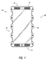
図1を参照すると、携帯電話10などのハンドヘルド電子デバイスが示されている。本明細書では主として携帯電話という文脈で説明されるが、本明細書では本発明は、携帯電話機能の有無にかかわらず、デジタルのスチルカメラおよび動画カメラ、小型ナビゲーション装置、モバイルインターネット機器、ハンドヘルドゲーム機、または以下で図8に関連して論じられる機能のいずれかもしくは組み合わせを有するデバイスを含む、様々なハンドヘルド電子デバイスのいずれにも利用可能である。
Referring to FIG. 1, a handheld electronic device such as a
携帯電話または他のハンドヘルド電子デバイスは、上縁部14および下縁部16を有するハウジング12を含むことができる。その通常使用する際の向きで電話を見ると、携帯電話10は左側部18、右側部20およびディスプレイ22を含む。ディスプレイ22は、当技術分野で理解されるように様々なアプリケーション、機能および情報を表示する。ディスプレイ22は、当技術分野で理解されるようにタッチスクリーン制御機構を組み込むこともできる。
A cell phone or other handheld electronic device can include a
ハウジング12の寸法は電話の製造業者および機能に応じて大きく異なることがある。例えば、HTCのスマートフォンは、高さ約104mm、幅約55mm、厚さ約12.8mmである。Samsung Galaxy S5は、高さ約142mm、幅約72.5mm、厚さ約8.1mmである。LG G2は、高さ約138.5mm、幅約70.9mm、厚さ約8.9mmである。Apple iPhone S5は、高さ約123.8mm、幅約58.6mm、厚さ約7.6mmである。本明細書に開示される本発明のいずれかを組み込む携帯電話および他のハンドヘルド電子デバイスが、上記に列挙される最小限から最大限の範囲内にあるか、または所望に応じてその範囲を超えるかもしくは下回ることができる。上述の市販の製品の全てにおいて、左側部18および右側部20は本質的に完璧に直線状である。対照的に、本明細書に開示される本発明のうちの少なくとも1つの態様による携帯電話または他の電子デバイスの左側部18および右側部20のうちの少なくとも一方は、把持を容易にするように曲がりくねった規則的な起伏のある表面を設けられる。
The dimensions of the
起伏のある表面または縁部は、滑りおよび落下の可能性の低下した、締まり嵌めもしくは摩擦を強化する表面構造またはデバイスの把持を容易にする構成を備えることができる。それらは、以下に論じられるものを含む様々な形態で設けることができる。一般に、表面構造は、好ましくは、アフターマーケットで入手できるような着脱可能な携帯電話保護ケースとは異なり、携帯電話のハウジングに恒久的に取り付けられる。強化された把持表面は、機械加工、射出成形または他の作業などによってハウジングと一体形成することができる。あるいは、その表面は、オーバーモールド、粘着剤による接合もしくは取り付けによって、ネジもしくは他の留め具を用いるような様々な技法のうちのいずれかによって、またははんだ付け、溶接、ろう付け、圧入干渉インターロック構造もしくは当技術分野で知られる他の取り付け技法などによって、製造または組み立ての時点で施すことができる。強化された把持表面は、好ましくは、意図される普通の使用の過程でユーザによる着脱が不能であり、顧客による着脱は破壊行為を必要とするか、またはデバイスの保証を無効にすることになる。このように、起伏のある表面は、一部の実施形態では、好ましくは、携帯電話または他のハンドヘルド電子デバイスの元々のハウジングの一部である。 The undulating surface or edge may be provided with a surface structure or configuration that facilitates gripping of the device that enhances an interference fit or friction with reduced likelihood of slipping and dropping. They can be provided in a variety of forms, including those discussed below. In general, the surface structure is preferably permanently attached to the cell phone housing, unlike removable cell phone protective cases such as those available in the aftermarket. The enhanced gripping surface can be integrally formed with the housing, such as by machining, injection molding or other operations. Alternatively, the surface can be overmolded, adhesive bonded or attached, by any of a variety of techniques such as using screws or other fasteners, or by soldering, welding, brazing, press interference interference It can be applied at the time of manufacture or assembly, such as by structure or other attachment techniques known in the art. The enhanced gripping surface is preferably non-detachable by the user in the course of normal use intended, and removal by the customer will require vandalism or will void the device warranty . Thus, the undulating surface is preferably part of the original housing of a cell phone or other handheld electronic device in some embodiments.
用語、凹所および突出部は、本明細書で用いられる通り、横向き外側を向く凹所が、凹所の側部を画定するように横向きに同じ方向に延びる2つの突出部間に画定されるように、横方向に平面状態から逸脱することを指すのに好都合な用語である。このように、用語、凹所および突出部は、別段の指定がない限り、相対的な空間の感覚で用いられ、それらが形成される様式を伝えるものではない。概略的には、基材の元々の右側表面に材料を追加することによって、またはここで突出部になる領域の両側にある基材の元々の右側表面から材料を除去することによって、または対応する右を向く突出部を形成するように基材の左側部を窪ませることによって、横を向く複数の突出部および凹所を生み出すためにジグザグ構成などになるように基材を曲げることによって、右への突出部を形成することができる。 The terms recess and protrusion, as used herein, are defined between two protrusions that extend laterally outward in the same direction to define a side of the recess. Thus, it is a convenient term to refer to deviating from the plane state in the lateral direction. As such, the terms, recesses and protrusions are used in the sense of relative space, unless otherwise specified, and do not convey the manner in which they are formed. In general, by adding material to the original right side surface of the substrate, or by removing material from the original right side surface of the substrate on either side of the region that now becomes the protrusion, or correspondingly Right by bending the substrate to form a zigzag configuration, etc. to create multiple protrusions and recesses facing sideways by recessing the left side of the substrate to form a right-facing protrusion Protrusions can be formed.
このように、横向きに延びる構造は、それを構築するための開始表面への突出部の追加または取り付けなどによって形成される、従来の意味の突出部とすることができるが、開始構成要素の元々の2つの部分の間にへこみまたは窪みが形成され、それにより、元々の表面が両側のへこみにより相対的な突出部を形成することを含むこともできる。このように、様々な製造技法のうちのいずれかを利用して、材料および所望の製造技法に応じて、本明細書に開示される本発明の1つまたは複数の態様による、携帯電話本体の滑らかでない横面の突出部およびへこみを設けることができる。突出部は、特にポリマー製ハウジングの場合は、射出成形または他の成形技法によって形成することができる。突出部は、基材の第1の側の圧痕および基材の反対側の対応する突出部を設けるように、スタンピング、圧印加工、または他の圧縮ステップもしくは曲げステップによって形成することができる。この例では基材は、ハウジングの横表面を形成するように後でフレームに取り付けられる材料のストリップ(例えば、ステンレス鋼、チタン、アルミニウムまたは他の金属)の形態とすることができる。あるいは、突出部は、粘着剤による接合、はんだ付け、ろう付け、溶接もしくは他の接合技法による、または締まり嵌め構造などの機械的嵌合による、またはネジ、リベットもしくは圧入構造などの留め具の使用による、基材への別個の構成要素の取り付けによって形成することができる。あるいは、本明細書の本開示に鑑みて、当業者によって理解されるように、突出部(および対応する、介在する凹所)は、研削、切削、EDM、レーザエッチングまたは他の機械加工もしくは除去技法などによって凹所を形成するように基材から材料を除去することによって形成することができる。 Thus, the laterally extending structure can be a conventional meaning protrusion, such as formed by the addition or attachment of a protrusion to the starting surface for constructing it, but originally from the starting component It is also possible that a dent or depression is formed between the two parts of the first surface, whereby the original surface forms relative protrusions with the dents on both sides. In this way, any of a variety of manufacturing techniques may be utilized, depending on the material and the desired manufacturing technique, of the mobile phone body according to one or more aspects of the invention disclosed herein. Non-smooth lateral projections and dents can be provided. The protrusions can be formed by injection molding or other molding techniques, particularly in the case of polymer housings. The protrusions can be formed by stamping, coining, or other compression or bending steps to provide indentations on the first side of the substrate and corresponding protrusions on the opposite side of the substrate. In this example, the substrate can be in the form of a strip of material (eg, stainless steel, titanium, aluminum or other metal) that is later attached to the frame to form the lateral surface of the housing. Alternatively, the protrusions may be joined by adhesives, soldering, brazing, welding or other joining techniques, or by mechanical fitting such as an interference fit structure, or by using fasteners such as screws, rivets or press fit structures Can be formed by attachment of separate components to the substrate. Alternatively, in view of the present disclosure herein, the protrusions (and corresponding intervening recesses) can be ground, cut, EDM, laser etched or other machined or removed, as will be appreciated by those skilled in the art. It can be formed by removing material from the substrate to form a recess, such as by a technique.
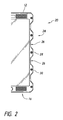
図2を参照すると、ハウジング12の右側部20の概略拡大図が示されている。左側部は右側部の鏡像であっても鏡像でなくてもよい。右側部20は、第1の突出部28と第2の突出部30との間に位置決めされる少なくとも1つの凹所26を有する起伏のある壁24を設けられる。少なくとも1つの凹所26、および概して少なくとも約2、3、4、5以上を右側部20上に設けることができる。図1に示される実施形態では、凹所26は4つ示されている。
Referring to FIG. 2, a schematic enlarged view of the
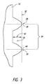
単一の凹所26の追加の詳細を図3に関連して見ることができる。外側の境界32とは、第1の突出部28および第2の突出部30のそれぞれの頂点に接触する想像線である。突出部が湾曲した表面を備える実施形態では、その外側の境界32は、第1の突出部28および第2の突出部30に対する接線を描くことになる。凹所26の幅34は、図3に示される実装形態では、接点38と40との間で測定することができる。突出部が図1に示されるような平坦な表面である実施形態では、凹所の幅34は、凹所の壁が外側の境界32から離れて凹所の中央の方向に入る点の間で測定される。
Additional details of the
凹所は、外側の境界32と凹所26の最も深い点との間で測定される深さ42を有すると考えることもできる。
The recess can also be considered to have a
凹所の幅34は、概して、外側の境界線32の方向に沿って測定されるハウジング12の高さ全体の、少なくとも約2%、多くの場合に少なくとも約4%または6%であり、一部の実施形態では、その10%以上にもなる。一部の実装形態では、幅34は、所望の性能に応じて、ハウジング12の高さの少なくとも約30%、一部の実装形態では、少なくとも約50%とすることができる。概して、各凹所26の幅34は、少なくとも約0.25インチ、多くの場合に少なくとも約0.5インチである。
The
最も深い点で測定される凹所26の深さ42は、典型的には、約1mm超であり、多くの場合に、少なくとも約2mmもしくは3mmまたはそれを超える。一部の実施形態では、深さ42は約4もしくは5mm、またはそれを超える。
The
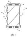
図1に示されるハウジングは線対称である。しかし、以下に説明するように非対称の構成が望ましいことがある。図4を参照すると、左側部18および右側部20を有する図1にあるような携帯電話ハウジングが示されている。しかし、左側部および右側部は、左側部18上に存在するより右側部上の凹所26が少ないことによって線対称でない。本明細書に開示される非対称の構成のいずれの鏡像も企図される。
The housing shown in FIG. 1 is axisymmetric. However, an asymmetric configuration may be desirable as described below. Referring to FIG. 4, a cell phone housing as in FIG. 1 having a
図示の実施形態では、第1の突出部28と第2の突出部30との間に単一の右側部凹所26が画定される。単一の凹所26は幅34が、電話の高さ全体の、少なくとも約30%、一部の実装形態では、少なくとも約50%、少なくとも約75%もしくは85%、またはそれを超える。この構成は、右手で操作するには最適な電話であると考えられることになる。当技術分野で理解されるように、手の構造は、親指の付け根に、母指球として知られる大きい丸みのあるこぶを含む。これは、短母指外転筋によって盛り上がるひとまとまりの筋肉の結果である。幅が少なくとも約1インチ、一部の実施形態では、少なくとも約1.5インチもしくは2インチもしくは2.5インチまたはそれを超える凹所26を設けることにより、母指球のためのクレードルを提供し、ハウジングの左側部18上の複数の別々の凹所26は、個々の指のための個々のクレードルを提供する。凹所26は電話ハウジングの高さの中間点を中心に線対称であるように図4に示されるが、凹所26の中間点は、上縁部14より下縁部16に近くなるように下方向にずらすことができる。このようにして、携帯電話のためのハウジングは、ユーザの手によりぴったりと沿うことができ、本明細書に開示される本発明のうちの少なくとも1つの、1つまたは複数の態様による携帯電話形状因子は、ユーザによってしっかりと掴むことができる起伏のある把持部の形態をとることができる。
In the illustrated embodiment, a single
図5を参照すると、携帯電話ハウジングの凹所の実施形態により、ユーザが携帯電話を掴んでいるときに指のそれぞれのための予測可能な着地点を提供できることが理解される。従って、凹所26の1つまたは複数に、電話または他のデバイスの様々な機能を制御する指用のボタンを配置することができる。ボタンまたは他の制御機構は、ボタンを作動させることなく通常の使用状況でユーザが携帯電話を掴むことができるように十分に高い作動力閾値を設けられ得る。しかし、電話を掴むために通常用いられるよりも大きい圧縮力を加える際に、ユーザは、所望に応じて選択的にボタンを作動させて電話の様々な機能を制御することができる。
Referring to FIG. 5, it will be appreciated that the recessed embodiment of the cell phone housing can provide a predictable landing point for each of the fingers when the user is holding the cell phone. Thus, one or more of the
このように、図5を参照すると、第1の凹所26は、人差し指によって作動させるようにボタン50などユーザが作動させる制御機構を設けられ得る。この例では、図示の携帯電話は、ユーザの右手によって操作するように構成される。第2の凹所26は、ユーザの中指によって作動させる第2の制御機構52を設けられ得る。ユーザの薬指および小指用の追加のボタン(図示せず)を設けることができる。
Thus, referring to FIG. 5, the
さらに、電話の右側部上の凹所26は、ユーザの親指によって作動させるボタンまたは他の制御機構54を設けられ得る。親指制御機構54は、約2インチ未満、好ましくは、約1インチ未満離間する第1の突出部28と第2の突出部30との間に画定される凹所26内に位置決めすることができる。母指球用のクレードルを設けるために、先に説明したようなより大きい凹所26が設けられる。
Further, the
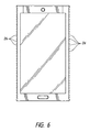
比較的短い幅の凹所26の実施形態が、図6に示されるような波形のまたは隆起のある表面を有するように見え始めることができる。本実装形態では、電話の側壁に沿って実際の幅1インチあたり少なくとも約5、少なくとも約10、一部の実装形態では、少なくとも約15またはそれを超える凹所26が存在することができる。ハウジングのプロフィルの追加の例が、実質的に一定の曲率半径を有する複数の凹所を示す図7Aに示される。
An embodiment of a relatively
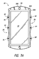
図7Aおよび図7Cを参照すると、上縁部14、下縁部16、左側部18および右側部20を有する携帯電話などのハンドヘルドデバイスが示されている。左側部18および右側部20はそれぞれ、本明細書においてほかの箇所でさらに詳細に論じられる、実質的に一様の複数の凹所またはうねりを設けられる。図示の実施形態は線対称であり、第1の左突出部62が第1の右突出部60の反対側に配設される。突出部62および突出部60は一緒に、電話の長手方向軸を横断する線上に方向付けられる反対向きの突出部の対を画定する。好ましくは、第1の突出部の対は、電話の上半分の位置に配置され、概して、電話の全体の高さの上部1/3または上部25%以内にある。
Referring to FIGS. 7A and 7C, a handheld device such as a mobile phone having an upper edge 14, a
第2の右突出部64を第2の左突出部66の反対側に設けることができる。右突出部60および64は一緒に、それらの間を延びる凹所26の範囲を画定する。第2の右突出部64および第2の左突出部66は一緒に第2の突出部の対を形成し、その対は、電話の上半分または3分の1以内に位置決めされる、左および右の凹所26を画定する。第2の右突出部64および第2の左突出部66の頂点は、電話の長手方向軸を横断する線を画定することができ、その線は、電話の長手方向の中間点から、電話の全長の約±30%からの範囲内、一部の実施形態では、約±15%からの範囲内、一部の実施形態では、約±5%以内の点で、電話の長手方向軸を横切ることができる。
A second
図示の実施形態では、第3の右突出部68が、第2対の凹所26を画定するように第3の左突出部70の反対側に配設される。第4の右突出部および第4の左突出部、ならびに第5の右突出部および第5の左突出部を、電話の所望の機能に応じて設けることができる。
In the illustrated embodiment, a third
図示の実施形態では、突出部の対は、電話の長手方向の中央線を中心に対称的に離間する。長手方向の長さが約6.25インチの実施形態では、第2の右突出部64および第2の左突出部66は、上縁部14または下側縁部16から約3.125インチの位置で電話の中間点を横切る線上にある。本実施形態では、各凹所26は実質的に一定の曲率半径を有し、その曲率半径は、概して、約0.5インチから約2.5インチの範囲内、多くの場合に、約1.0インチから約2.0インチの範囲内にあり、一実装形態では、その半径は約1.3インチから約1.8インチの範囲内にある。各凹所26内の表面の曲率は、表面の曲線が円の表面の一部分に実質的に一致するように実質的に一定とすることができる。或いは、凹所26の曲率は、楕円または円環の表面の一部分に一致する表面など、非円形とすることもできる。本明細書で用いられる通り、半径とは、半径が一定の曲線の半径、ならびに凹所26の一定でない半径曲率に最もうまく収まる半径が一定の曲線の半径を指す。
In the illustrated embodiment, the pairs of protrusions are spaced symmetrically about the longitudinal centerline of the phone. In an embodiment having a longitudinal length of about 6.25 inches, the second
隣接する突出部の頂点から凹所26の曲線の表面に沿って測定される弧の長さは、概して、約0.5インチから約2.5インチの範囲内、多くの場合に、約1.0インチと2.0インチとの間、または約1.2インチおよび約1.8インチ以内にある。
The length of the arc measured along the curved surface of the
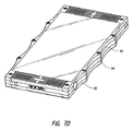
線72が、電話の長手方向軸に平行に測定される、上側縁部14および下側縁部16の電話の幅を図示する。図示の実施形態の線72は、突出部を含まない電話を囲繞する、最もうまく収まる矩形の辺である。線74は、隣接する突出部の頂点から頂点への接線に沿って引かれる、電話の最も外側の幅の境界を図示する。このように、凹所26は、電話の外周を囲繞する、最もうまく収まる矩形の領域に対して、電話の壁から除去される材料の領域を表すことができる。
基準線72と基準線74との間の直線距離は、概して、少なくとも約0.050インチ、多くの場合に、少なくとも約0.0625インチ、好ましくは、少なくとも約0.125インチである。
The linear distance between the
電話の前面プレートと背面プレートとを互いに連結するための第1のネジまたは他の留め具76を複数設けることができる。突出部内で右側部20および左側部18に沿って、少なくとも2箇所の、好ましくは、少なくとも4箇所または6箇所の留め具76を好都合に位置決めすることができ、したがって、電話全体の大きさに対して電話の視聴面の幅を最大にできるように、留め具76を「ボードの外にある」状態で運ぶことが可能になる。
There may be a plurality of first screws or
第2組の留め具78を、2箇所の留め具が視聴画面の上方に配置され、2箇所の留め具が視聴画面の下方に配置されるように設けることができる。したがって、それら留め具は、視聴画面を犠牲にすることなく、電話の中間線に向かって放射状に挿入することができる。カメラレンズ84と同様に、視聴画面の上方に左上のスピーカ80および右上のスピーカ82を設けることができる。左下のスピーカ83および右下のスピーカ86を設けることができると共に、視聴画面の下方など電話上に少なくとも1つのマイクロフォンを設けることができる。
The second set of
図7Dを参照すると、図7Cに示される実施形態の斜視図が示されている。図示の実施形態では、前面プレート90および後面プレート92が、電話の電子部品を封入するようにサンドイッチ構成になるように中間フレーム94によって離間する。封入された電子部品チャンバを設けるために、前面プレート90と後面プレート92とを複数の留め具が互いに締結する。
Referring to FIG. 7D, a perspective view of the embodiment shown in FIG. 7C is shown. In the illustrated embodiment, the
好ましくは、カメラは、デバイス10で使用される画像センサのサイズおよび支持電子部品の容量に応じて、様々なおよび/または調整可能な解像度ならびにアスペクト比で、例えば、限定されるものではないが、6144×3160画素またはそれを超える画素、2:1、2.4:1、16:9などのアスペクト比で、静止画像を取り込む能力と、限定されるものではないが、例えば、6K(2:1、2.4:1)、5K(フルフレーム、2:1、2.4:1およびアナモルフィック2:1)、4.5K(2.4:1)、4K(16:9、HD、2:1およびアナモルフィック2:1)、3K(16:9、2:1およびアナモルフィック2:1)、2K(16:9、2:1およびアナモルフィック2:1)、1080p RGB(16:9)、720p RGB(16:9)ならびに他の解像度およびフォーマット含む、最大約「6K」またはそれを超える解像度で動画像を取り込む能力とを含む。さらに、デバイス10は、圧縮ローモザイク画像センサデータ、十分にレンダリングされた圧縮ビデオデータ、および非圧縮ビデオデータを含む、いくつかの圧縮オプションを含むように構成することができる。オンボードメモリが、好ましくは、少なくとも約64GB、一実装形態では、少なくとも約128GBの容量を備える。電話は、少なくとも1つ、好ましくは、電話が2つ以上の電話番号を受け付けることが可能になるように2つ以上のSIMカードを受け入れるスロットまたは空所を含む。カメラが2つ設けられ、1つは電話の前面から外側を向き、1つは電話の後面から外側を向く。
Preferably, the camera is of various and / or adjustable resolutions and aspect ratios depending on the size of the image sensor used in the
続けて図7Aおよび図7Bを参照すると、デバイス10は、任意選択で個人用の照明(例えば、懐中電灯)または写真のために使用できる、照明を1つまたは複数含むことができる。例えば、上記に記載するように、デバイス10はカメラレンズ84を含むことができる。任意選択では、デバイス10は、レンズ84と同じ方向を向くデバイス10の前面に配設される照明デバイス200を含むことができる。照明デバイス200は、任意のタイプの照明デバイスとすることができ、一部の実施形態では、「フラッシュ撮影」に使用されるような「フラッシュ」出力の強度が高くなるように構成される。さらに、一部の実施形態では、照明デバイス200は、ユーザの所望に応じて照明を供給するように、懐中電灯モードなどで連続的に動作するように構成することもできる。同様に、照明デバイス200は、動画ビデオを記録するためのカメラレンズ84の使用中に連続的に動作するように構成することができる。一部の実施形態では、照明デバイス200は1つまたは複数のLEDの形態とすることができる。LEDに基づいた設計を含むこのタイプの照明デバイスの設計および動作は、当技術分野でよく知られている。
With continued reference to FIGS. 7A and 7B, the
任意選択では、図7Aに示されるように、照明デバイス200は、図8を参照しながら以下に説明する第1のカメラ151に関連してカメラレンズ84の周囲に沿って延びることができる。したがって、照明デバイス200は、「リングライト」または「リングフラッシュ」として知られる照明デバイスによってもたらされるのと同様の効果をもたらすことができる。一部の実施形態では、照明デバイス200は、LEDなど2つ以上の発光デバイスおよびつや消し表面を施した透明の材料などの光拡散器を用いて構築することができる。さらに、照明デバイス200は、そこから放射される光の色または温度に関して調節可能になるように構成される発光デバイスを含むことができる。例えば、照明デバイス200内に含まれる発光デバイスは、典型的には写真に使用される「温度」の異なる白色光を放射するように構成することができる。さらに、照明デバイス200は、例えば、「RGB」LED発光デバイスを用いて、広範囲の異なる色の光を放射するように構成することができる。このようなLEDデバイスは、その動作制御と同様に、広く知られており、市販されている。
Optionally, as shown in FIG. 7A, the
一部の実装形態では、デバイス10は、照明デバイス202を含むことができる。図7Aに示される実施形態に示すように、照明デバイス202は、外周に沿って延びる構成を含むことができる。例えば、照明デバイス202は、ディスプレイ22の周りを延びることができる。照明デバイス200と同様にまたは同じく、照明デバイス202は、LEDなど複数の発光デバイスを用いて構築することができ、それら発光デバイスは、白色温度のある範囲内で調節可能な白色または「RGB」LED照明デバイスなどの広範囲の色とすることができる。さらに、照明デバイス202は、所望に応じて動画ビデオを記録するなどの個人的な照明の用途のための連続的なまたは実質的に連続的な出力のために、懐中電灯モードまたは他のモードで写真のための「フラッシュ」モードを制御するように構成することができる。さらに、デバイス10は、デバイス10からの音声出力と同期されても同期されなくてもよい光変更スキームなどのさらなる娯楽目的で照明デバイス202を動作させるためのプログラミングを含むことができる。このような制御オプションおよび技法は当技術分野でよく知られている。
In some implementations, the
照明デバイス200、202の代替案としてまたは照明デバイス200、202と組み合わせて、デバイス10は照明デバイス204を含むこともできる。図7Aに示すように、照明デバイス204は、デバイス10の周囲の縁部に沿って配設することができる。図示の実施形態では、照明デバイス204は、デバイス10の外周の形状に沿ってたどり、凹所26の一部を含むかまたは画定する。さらに、照明デバイス202と同様に、照明デバイス204は、光画像デバイスによって放射される光を拡散するように半透明のカバーで覆われるLEDなど複数の発光デバイスを含むことができる。他の実施形態では、照明デバイス200、202、204のいずれかの代替案としてまたはそれらと組み合わせて、デバイス10は、上記で説明したネジ76のうちの1つまたは複数の頂部に配置される光画像デバイスを含むことができる。
As an alternative to or in combination with
図7Bを参照すると、デバイス10の背面は、図8を参照しながら以下に説明する、例えば、第2のカメラ152と一緒に使用するためのカメラレンズ85を含むことができる。照明デバイス200と同様のまたは同一の構成を用いて、デバイス10は、レンズ85の周囲の一部にまたは全体に配設される光照明デバイス206を含むこともできる。さらに、照明デバイス206の代替案としてまたはそれを組み合わせて、デバイス10は、デバイス10の背面の周囲に沿って延びる照明デバイス208を含むことができる。照明デバイス208は、照明デバイス200、202、すなわち、上記で言及した4つのうちの2つと同様にまたは同一になるように構築することができる。
Referring to FIG. 7B, the back surface of the
リング形状の照明デバイス200、206、もしくは矩形の照明デバイス202、204、208、またはさらにカメラレンズ84、85などのカメラレンズに対して複数の点に配設される複数の照明デバイスの使用によってもたらされるようなより拡散される光の放射特徴を照明デバイスに与えることによって、異なる照明の美しさを実現することができる。一部の写真のための技法では、より拡散される照明の使用は、例えば、よりソフトな縁部および/または他の効果を有する影を発生させることによって、改善される結果および/またはより望ましい結果をもたらすことができる。
Produced by the use of multiple illumination devices disposed at multiple points relative to a camera lens, such as a ring-shaped
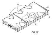
図7Eを参照すると、一部の実装形態では、デバイス10は、デバイス10の前面に延びない凹所27を含むことができる。例えば、図7Eは、凹所26が、デバイス10の背面ならびに側部18、20のうちの一方または両方に画定される凹所27の形態にある代替の実施形態を示す。図7Eは、デバイス10の背面および左側部18上に部分的に画定される凹所27を複数示す。しかし、デバイス10の前面の左側部18の間の縁部29が、概してまっすぐな線に沿って延びる。これは、図示の実施形態では、凹所27が縁部29を越えてまたはデバイス10の前面に延びることがないからである。このように、図7Eに示されるデバイス10の実施形態は、上面図では矩形になるように見え、言い換えると、凹所27は前面の上面図(図7Aに対応する図)では概して見えないことになる。
Referring to FIG. 7E, in some implementations, the
一部の実装形態では、凹所27は、デバイス10の厚さの約75%の最大深さ31を有することができるが、他の深さを用いることもできる。さらに、凹所27は、深さ31の大きさより小さいか、深さ31の大きさとほぼ同じか、または深さ31の大きさの最大2から3倍の長さ33を有することができる。しかし、凹所27の他の構成を用いることもできる。図7Eの実施形態の文脈では、凹所27に隣接する一段高い領域が、間に凹所27を画定する突出部35を左側部18に形成するものと解釈することができる。
In some implementations, the
図8は、本開示の実施形態によるデバイスの様々な追加の電子面および特性を示すブロック図である。上記で説明した実施形態のハウジングは、様々な特性のいずれかを有する電子デバイスと共に利用することができ、以下は単なる例示であり、本発明を限定するものではない。可能性のある電子面の追加の詳細は、例えば、2014年2月27日公開の米国特許出願公開第2014/0055394号に見ることができ、その内容はその全体が本明細書に援用される。 FIG. 8 is a block diagram illustrating various additional electronic surfaces and characteristics of a device according to an embodiment of the present disclosure. The housings of the embodiments described above can be used with electronic devices having any of a variety of characteristics, the following are merely examples and do not limit the invention. Additional details of possible electronic surfaces can be found, for example, in US Patent Application Publication No. 2014/0055394, published February 27, 2014, the contents of which are incorporated herein in their entirety. .
図8を参照すると、実施形態による携帯電話などの電子デバイス100は、下位通信モジュール130、コネクタ165およびイヤホン接続ジャック167などの外部接続デバイスを用いることによって、外部デバイスと接続することができる。「外部デバイス(external device)」は、電子デバイスから着脱可能でありケーブルを介して電子デバイスに接続される、イヤホン、外部スピーカ、ユニバーサルシリアルバス(USB:Universal Serial Bus)メモリ、充電器、クレードル/ドック、デジタルマルチメディア放送(DMB:Digital Multimedia broadcasting)アンテナ、支払関連の電子デバイス、ヘルスケアデバイス(例えば、血糖試験器)、ゲーム機、車両ナビゲーションなどの様々なデバイスを含むことができる。「外部デバイス」は、BLUETOOTH、つまり、BLUETOOTH SPECIAL INTEREST GROUP, INC.から市販される2.4GHz帯域の近距離無線通信技術、近距離場通信(NFC:Near Field Communication)などの近距離通信によって、電子デバイス100に無線接続できる近距離通信デバイスと、WI−FI DIRECT、つまり、WI−FI ALLIANCEから市販されるコンピュータネットワーク上のデータ交換のための無線技術、無線アクセスポイント(AP:Access Point)などを用いる通信デバイスも含むこともできる。さらに、外部デバイスは、携帯電話、スマートフォン、タブレットPC、デスクトップPC、サーバなど任意の他のデバイスを含むことができる。
Referring to FIG. 8, the
図8を参照すると、電子デバイス100は、ディスプレイユニット190およびディスプレイコントローラ195を含む。電子デバイス100は、コントローラ110、移動通信モジュール120、下位通信モジュール130、マルチメディアモジュール140、カメラモジュール150、全地球測位システム(GPS:Global Positioning System)モジュール155、入力/出力モジュール160、センサモジュール170、記憶装置175および電力供給装置180も含む。下位通信モジュール130は、無線ローカルエリアネットワーク(WLAN:Wireless Local Area Network)131および近距離通信モジュール132のうちの少なくとも1つを含み、マルチメディアモジュール140は、放送通信モジュール141、音声再生モジュール142および動画再生モジュール143のうちの少なくとも1つを含む。カメラモジュール150は、第1のカメラ151、第2のカメラ152、第3のカメラ153のうちの少なくとも1つを含み、入力/出力モジュール160は、ボタン161、マイクロフォン162、スピーカ163、振動モータ164、コネクタ165、およびキーパッド166のうちの少なくとも1つを含む。一部の実装形態では、第2のカメラ152および第3のカメラ153は、両方とも、3‐Dのスチル写真撮影または動画ビデオを含む様々なタイプの写真用ツールならびに他のタイプの部材を収容するようにデバイス10の背面に配設することができる。さらに、電子デバイス100は照明を1つまたは複数含むことができ、例えば、上記で説明した照明200、202、204は「第1の照明」として概略的に図示される。さらに、照明デバイス206、208は「第2の照明」として概略的に図示される。
Referring to FIG. 8, the
コントローラ110は、中央処理装置(CPU:Central Processing Unit)111、電子デバイス100を制御するためにオペレーティングシステム(OS:Operating System)などの制御プログラムを格納するリードオンリーメモリ(ROM:Read Only Memory)112、外部供給源から入力される信号もしくはデータを格納するための、または電子デバイス100内の作業結果のメモリ空間として使用されるためのランダムアクセスメモリ(RAM:Random Access Memory)113を含むことができる。CPU111は、シングルコア、デュアルコア、トリプルコアまたはクアッドコアを含むことができる。CPU111、ROM112、およびRAM113は内部バスを介して互いに接続することができる。
The
コントローラ110は、移動通信モジュール120、下位通信モジュール130、マルチメディアモジュール140、カメラモジュール150、GPSモジュール155、入力/出力モジュール160、センサモジュール170、記憶装置175、電力供給装置180、ディスプレイユニット190およびディスプレイコントローラ195を制御することができる。
The
移動通信モジュール120は、コントローラ110の制御下で、少なくとも1対1型アンテナまたは1対多型アンテナを用いる移動通信によって電子デバイス100を外部デバイスに接続する。移動通信モジュール120は、電子デバイス100に入力された電話番号を有する電話で、音声通話、テレビ電話会議、ショートメッセージサービス(SMS:Short Message Service)メッセージ、またはマルチメディアメッセージサービス(MMS:Multimedia Message Service)メッセージのための無線信号を、携帯電話、スマートフォン、タブレットPC、または別のデバイスに送信/から受信する。
The
下位通信モジュール130は、WLANモジュール131および近距離通信モジュール132のうちの少なくとも1つを含むことができる。例えば、下位通信モジュール130は、WLANモジュール131もしくは近距離通信モジュール132のいずれか、または両方を含むことができる。
The
WLANモジュール131は、コントローラ110の制御下で無線アクセスポイント(AP)がある場所でInternetに接続することができる。WLANモジュール131は、WLANアメリカ電気電子通信学会(IEEE:Institute of Electrical and Electronics Engineers)802.11x規格をサポートする。近距離通信モジュール132は、コントローラ110の制御下で電子デバイス100と画像レンダリングデバイスとの間の近距離通信を実行することができる。近距離通信は、BLUETOOTH、つまり、BLUETOOTH SPECIAL INTEREST GROUP, INC.から市販される2.4GHz帯域の近距離無線通信技術、赤外線通信協会(IrDA:Infrared Data Association)、WI−FI DIRECT、WI−FI ALLIANCEから市販されるコンピュータネットワーク上のデータ交換のための無線技術、NFCなどと互換性のある通信を含むことができる。
The
電子デバイス100は、電子デバイス100の性能要件に基づいて、移動通信モジュール120、WLANモジュール131および近距離通信モジュール132のうちの少なくとも1つを含むことができる。例えば、電子デバイス100は、電子デバイス100の性能要件に基づいて、移動通信モジュール120、WLANモジュール131および近距離通信モジュール132の組み合わせを含むことができる。
The
マルチメディアモジュール140は、放送通信モジュール141、音声再生モジュール142または動画再生モジュール143を含むことができる。放送通信モジュール141は、コントローラ110の制御下で、放送通信アンテナを通して放送局から送信される放送信号(例えば、テレビジョン放送信号、ラジオ放送信号またはデータ放送信号)および追加の放送情報(例えば、電子番組ガイド(EPG:Electric Program Guide)または電子サービスガイド(ESG:Electric Service Guide)を受信することができる。音声再生モジュール142は、コントローラ110の制御下で格納または受信されるデジタルオーディオファイル(例えば、mp3、wma、oggまたはwav(way)などの拡張子を有するファイル)を再生することができる。動画再生モジュール143は、コントローラ110の制御下で格納または受信されるデジタルビデオファイル(例えば、mpeg、mpg、mp4、avi、mov(move)またはmkvなどの拡張子を有するファイル)を再生することができる。動画再生モジュール143はデジタルオーディオファイルを再生することもできる。
The
マルチメディアモジュール140は、放送通信モジュール141を除いて、音声再生モジュール142および動画再生モジュール143を含むことができる。マルチメディアモジュール140の音声再生モジュール142または動画再生モジュール143をコントローラ110に含むことができる。
The
カメラモジュール150は、コントローラ110の制御下で、静止画像またはビデオ画像を取り込む第1のカメラ151および第2のカメラ152のうちの少なくとも1つを含むことができる。さらに、第1のカメラ151または第2のカメラ152は、画像を取り込むためのある量の光を供給する補助光源(例えば、フラッシュ)をそれぞれ含むことができる。第1のカメラ151は電子デバイス100の前面に配置することができ、第2のカメラ152は電子デバイス100の背面に配置することができる。あるいは、第1のカメラ151および第2のカメラ152は、3次元(3D)静止画像または3Dビデオ画像を取り込むように、互いに隣接するようにそれぞれ配置される(例えば、第1のカメラ151と第2のカメラ152との間の距離はそれぞれ1cmから8cmの範囲とすることができる)。
The
GPSモジュール155は、地球周回軌道の複数のGPS衛星から無線信号を受信し、GPS衛星から電子デバイス100への到着時間を用いることによって電子デバイス100の位置を算定することができる。
The
入力/出力モジュール160は、複数のボタン161、マイクロフォン162、スピーカ163、振動モータ164、コネクタ165およびキーパッド166のうちの少なくとも1つを含むことができる。
The input /
ボタン161のうちの少なくとも1つは、電子デバイス100のハウジングの前面、側面または背面に配置することができ、電源/ロックボタン、音量ボタン、メニューボタン、ホームボタン、戻るボタンおよび検索ボタンのうちの少なくとも1つを含むことができる。
At least one of the
マイクロフォン162は、コントローラ110の制御下で、声または音を受信することによって電気信号を発生させる。
The
スピーカ163は、コントローラ110の制御下で、移動通信モジュール120、下位通信モジュール130、マルチメディアモジュール140またはカメラモジュール150からの様々な信号(例えば、無線信号、放送信号、デジタルオーディオファイル、デジタルビデオファイルまたは写真撮影信号)に対応する音を外部に出力することができる。スピーカ163は、電子デバイス100によって行われる機能に対応する音(例えば、ボタン押し音または呼び出し音)を出力することができる。電子デバイス100のハウジング上またはハウジング内の少なくとも1つの位置に1つまたは複数のスピーカ163を配置することができる。
The
振動モータ164は、コントローラ110の制御下で、電気信号を機械振動に変換することができる。例えば、振動モードの電子デバイス100は、別のデバイスから音声呼び出しを受けるときに振動モータ164を動作させる。電子デバイス100のハウジングの内側に少なくとも1つの振動モータ164があってよい。振動モータ164は、ディスプレイユニット190上のユーザのタッチ行為または連続するタッチに応答して動作することができる。
The
コネクタ165は、電子デバイス100を外部のデバイスまたは電源に接続するインターフェースとして用いることができる。コントローラ110の制御下で、電子デバイス100は、コネクタ165に接続されるケーブルを介して、電子デバイス100の記憶装置175に格納されるデータを外部デバイスに送信するか、または外部デバイスからデータを受信することができる。さらに、電子デバイス100は、コネクタ165に接続されるケーブルを介して電源から電力を受けることができるか、または電源を用いてバッテリを充電することができる。
The
キーパッド166は、電子デバイス100を制御するためにユーザからキー入力を受信することができる。キーパッド166は、電子デバイス100上に形成される機械キーパッドまたはディスプレイユニット190上に表示される仮想キーパッドを含む。電子デバイス100に形成される機械キーパッドは、任意選択で、電子デバイス100の性能要件または構造に応じて電子デバイス100の実装形態から省略することができる。
The
イヤホン接続ジャック167にイヤホンを挿入することができ、したがって、そのイヤホンを電子デバイス100に接続することができる。
An earphone can be inserted into the
電子デバイス100にスタイラスペン168を挿入し、着脱可能なように保持することができ、そのスタイラスペン168を電子デバイス100から抜き出し、取り外すことができる。
The
スタイラスペン168の取り付けおよび取り外しに応答して動作するペン着脱認識スイッチ 169が、電子デバイス100内のうちスタイラスペン168が着脱可能なように保持される領域に設けられ、スタイラスペン168の取り付けまたは取り外しに対応する信号をコントローラ100に送る。ペン着脱認識スイッチ169は、スタイラスペン168がその領域に挿入されると、スタイラスペン168と直接的または間接的な接触を有することができる。ペン着脱認識スイッチ169は、直接的または間接的な接触に基づいてスタイラスペン168の取り付けまたは取り外しに対応する信号を発生させ、その信号をコントローラ110に供給する。
A pen attachment /
センサモジュール170は、電子デバイス100の状態を検出するセンサを少なくとも1つ含む。例えば、センサモジュール170は、電子デバイス100へのユーザの接近を検出する近接センサと、電子デバイス100の周辺光の量を検出する照明センサと、電子デバイス100のモーション(例えば、電子デバイス100の回転、電子デバイス100に加えられる加速または振動)を検出するモーションセンサと、地球磁場を用いてコンパスの先を検出する地磁気センサと、重力の方向を検出する重力センサと、大気圧を測定することによって高度を検出する高度計とを含むことができる。少なくとも1つのセンサが、状態を検出し、対応する信号を発生させて、コントローラ110に送信することができる。センサモジュール170のセンサは、電子デバイス100の電子デバイス100の性能要件に応じて追加または着脱することができる。
The
記憶装置175は、コントローラ110の制御下で、移動通信モジュール120、下位通信モジュール130、マルチメディアモジュール140、カメラモジュール150、GPSモジュール、入力/出力モジュール160、センサモジュール170、ディスプレイユニット190によって入力/出力される信号またはデータを格納することができる。記憶装置175は、電子デバイス100またはコントローラ110を制御するための制御プログラムおよびアプリケーションを格納することができる。
The storage device 175 is input / output by the
用語「記憶装置(storage)」は、記憶装置175を指し、コントローラ110のROM112、RAM113、または電子デバイス100にインストールされるメモリカード(例えば、セキュアデジタル(SD:Secure Digital)カード、メモリスティックなど)も指す。記憶装置は、不揮発性メモリ、揮発性メモリ、ハードディスクドライブ(HDD:Hard Disc Drive)、半導体ドライブ(SSD:Solid State Drive)などを含むこともできる。
The term “storage device” refers to the storage device 175, and is a memory card (eg, a secure digital (SD) card, a memory stick, etc.) installed in the
電力供給装置180は、コントローラ110の制御下で、電子デバイス100のハウジング内に配置される少なくとも1つのバッテリに電力を供給することができる。少なくとも1つのバッテリは電子デバイス100に電力供給する。電力供給装置180は、コネクタ165に接続されるケーブルを介して外部電源から入力される電力を電子デバイス100に供給することができる。電力供給装置180は、無線充電技術を用いて外部電源から無線電力を電子デバイス100に供給することもできる。
The
ディスプレイコントローラ195は、コントローラ110によって処理される情報(例えば、電話、データ伝送、放送または撮影を行うために生み出される情報)を受信し、その情報をディスプレイユニット190上に表示されるデータに変換し、そのデータをディスプレイユニット190に供給する。ディスプレイユニット190は、ディスプレイコントローラ195から受信されるデータを表示する。例えば、通話モードでは、ディスプレイユニット190は、呼び出しに対するユーザインタフェース(UI:User Interface)またはグラフィックユーザインターフェース(GUI:Graphic User Interface)を表示することができる。ディスプレイユニット190は、液晶ディスプレイ、薄膜トランジスタ液晶ディスプレイ、有機発光ダイオード、フレキシブルディスプレイ、3Dディスプレイ、電気泳動ディスプレイなどのうちの少なくとも1つを含むことができる。
The
ディスプレイユニット190は、出力デバイスとして、さらに入力デバイスとしても使用することができ、後者の場合、タッチスクリーンとして動作するようにタッチスクリーンパネルを有することができる。ディスプレイユニット190は、UIまたはGUIへの少なくとも1つのタッチに対応するアナログ信号を、ディスプレイコントローラ195に送ることができる。ディスプレイユニット190は、ユーザの身体的接触による(例えば、親指を含む指による)、またはタッチ可能な入力デバイス(例えば、スタイラスペン)による少なくとも1つのタッチを検出することができる。ディスプレイユニット190は、少なくとも1つのタッチの中のタッチのドラッギングの動きを受信し、ドラッギングの動きに対応するアナログ信号をディスプレイコントローラ195へ送信することができる。ディスプレイユニット190は、例えば、抵抗法、容量法、赤外線法、音波法などで少なくとも1つのタッチを検出するように実装することができる。
The
用語「タッチ(touch)」は、ユーザの身体的な接触またはタッチ可能な入力デバイスを用いた接触による物理的なタッチに限定されるものではなく、タッチしない近接を含むこともできる(例えば、ディスプレイユニット190とユーザの身体またはタッチ可能な入力デバイスとの間で検出可能な距離を1mm未満に維持する)。ディスプレイユニット190から検出可能な距離は、電子デバイス100の性能要件または電子デバイス100の構造に応じて変更することができ、より具体的には、ディスプレイユニット190は、タッチ事象がユーザの身体またはタッチ可能な入力デバイスとの接触と、接触なしの入力(例えば、ホバリング事象)とによって起きたことを区別して検出するように、タッチ検出およびホバリング検出のための異なる値(例えば、電流値)を出力することができる。さらに、ディスプレイユニット190は、ホバリング事象が起きる位置からの距離に対してホバリング検出について異なる値(例えば、電流値)を出力することができる。
The term “touch” is not limited to physical touch by a user's physical contact or touch using a touchable input device, but can also include non-touch proximity (eg, display Maintain a detectable distance of less than 1 mm between the
ディスプレイコントローラ195は、ディスプレイユニット190から受信するアナログ信号をデジタル信号(例えば、タッチパネルまたはディスプレイスクリーン上のXY座標)に変換し、そのデジタル信号をコントローラ110に送信する。コントローラ110は、ディスプレイコントローラ195から受信するデジタル信号を使用することによってディスプレイユニット190を制御することができる。例えば、タッチ事象またはホバリング事象に応答して、コントローラ110は、ディスプレイユニット190上に表示されるショートカットアイコンを選択可能または実行可能にすることができる。ディスプレイコントローラ195は、コントローラ110に組み込むこともできる。
The
さらに、ディスプレイコントローラ195は、ディスプレイユニット190を通して出力される値(例えば、電流値)を検出することによってホバリング事象が起きる位置とディスプレイユニット190との間の距離を判定し、判定された(例えば、Z座標による)距離をデジタル信号変換し、そのデジタル信号をコントローラ110に供給することができる。
Further, the
さらに、実装形態に応じて、電子デバイス100はディスプレイユニットを2つ以上有することができる。
Furthermore, depending on the implementation, the
ディスプレイユニット190は、ユーザの身体またはタッチ可能な入力デバイスによってタッチスクリーンパネルへのタッチまたは近接を検出して、ユーザの身体またはタッチ可能な入力デバイスによる入力を両方同時に受信するように、タッチスクリーンパネルを少なくとも2つ含むことができる。少なくとも2つのタッチスクリーンパネルは、ディスプレイコントローラ195に異なる出力値を供給し、ディスプレイコントローラ195は、少なくとも2つのタッチスクリーンパネルから入力される値を異なるように認識することによって、タッチスクリーンを通したユーザの身体による入力とタッチ可能な入力デバイスによる入力を見分けることができる。
The
図1〜図7Eに関連して説明されるものを含む、本明細書に記載されるハンドヘルド電子デバイスはいずれも、図8に関連して図示および説明される構成要素のうちの一部または全部ならびに対応する機能を組み込むことができる。さらに、本明細書に図示および説明される一定の電子デバイスは携帯電話であるが、他のハンドヘルド電子デバイスの実施形態は携帯電話ではなく、電話能力を含まない。例えば、一部の実施形態は、図1〜図7Eのいずれかに関連して図示および説明されるデバイスと同じかまたは同様の外装を有するが、タブレットコンピュータデバイスまたはデジタルカメラの場合などでは電話能力は含まない。それでも、このような実施形態は、コントローラ110、タッチスクリーン190およびタッチスクリーンコントローラ195、カメラモジュール150マルチメディアモジュール140、下位通信モジュール130、第1の照明200、202、204、第2の照明206、208、GPSモジュール155、I/Oモジュール160、およびメモリ176のうちの1つまたは複数またはそれらの一部など、図8に関連して説明される電話でない構成要素および機能のどの組み合わせも含むことができる。
Any of the handheld electronic devices described herein, including those described in connection with FIGS. 1-7E, may include some or all of the components shown and described in connection with FIG. As well as corresponding functions. Further, while certain electronic devices shown and described herein are mobile phones, other handheld electronic device embodiments are not mobile phones and do not include telephone capabilities. For example, some embodiments have the same or similar exterior as the device shown and described in connection with any of FIGS. 1-7E, but in the case of a tablet computer device or digital camera, etc., telephone capabilities Is not included. Nevertheless, such an embodiment includes the
本明細書で用いられる通り、項目リストのうちの「〜のうちの少なくとも1つ(at least one of)」に言及する句は単一の部材を含むそれら項目のどの組み合わせも指す。一例として、「a、bまたはcのうちの少なくとも1つ(at least one of:a、b, or c)」は、a、b、c、a−b、a−c、b−cおよびa−b−cを包含するものとする。 As used herein, the phrase referring to “at least one of” in a list of items refers to any combination of those items including a single member. By way of example, “at least one of a, b or c” is a, b, c, ab, ac, bc and a. -B-c shall be included.
本明細書に開示される実装形態に関連して説明される様々な例示的な論理、論理ブロック、モジュール、回路およびアルゴリズムステップは、電子ハードウェア、コンピュータソフトウェアまたはそれらの組み合わせとして実装することができる。ハードウェアとソフトウェアとの互換性を機能面から概略的に説明し、上記で説明した様々な例示的な構成要素、ブロック、モジュール、回路およびステップにおいて図示した。このような機能がハードウェアに実装されるかソフトウェアに実装されるかは、システム全体に課される特定のアプリケーションおよび設計の制約に応じて変わる。 Various exemplary logic, logic blocks, modules, circuits, and algorithm steps described in connection with the implementations disclosed herein can be implemented as electronic hardware, computer software, or a combination thereof. . Hardware and software compatibility is schematically described in terms of functionality and illustrated in the various exemplary components, blocks, modules, circuits, and steps described above. Whether such functionality is implemented in hardware or software depends on the particular application and design constraints imposed on the overall system.
本明細書に開示される態様に関連して説明される様々な例示的な論理、論理ブロック、モジュールおよび回路を実装するために使用されるハードウェアおよびデータ処理装置は、本明細書に説明される機能を実行するように設計されるシングルチッププロセッサもしくはマルチチッププロセッサ、デジタル信号プロセッサ(DSP:digital signal processor)、特定用途向け集積回路(ASIC:application specific integrated circuit)、フィールドプログラマブルゲートアレイ(FPGA:field programmable gate array)もしくは他のプログラム可能な論理デバイス、ディスクリートゲートもしくはトランジスタ論理、ディスクリートハードウェアコンポーネント、またはそれらの任意の組み合わせを用いて実装または実行することができる。プロセッサは、マイクロプロセッサでもよく、任意のプロセッサ、コントローラ、マイクロコントローラまたは状態機械でもよい。DSPおよびマイクロプロセッサ、複数のマイクロプロセッサ、DSPコアと関連する1つまたは複数のマイクロプロセッサ、または任意の他のこのような構成の組み合わせなど、電子デバイスの組み合わせとして、プロセッサを実装することもできる。一部の実装形態では、特定のステップおよび方法は、所与の機能に特有の回路によって行うことができる。 The hardware and data processing apparatus used to implement the various exemplary logic, logic blocks, modules and circuits described in connection with aspects disclosed herein are described herein. Single-chip or multi-chip processors, digital signal processors (DSPs), application specific integrated circuits (ASICs), field programmable gate arrays (FPGAs) that are designed to perform these functions field programmable gate array) or other programmable logic device, discrete gate or transistor logic, discrete Hardware components, or any combination thereof, can be implemented or implemented. The processor may be a microprocessor or any processor, controller, microcontroller or state machine. The processor may also be implemented as a combination of electronic devices, such as a DSP and a microprocessor, a plurality of microprocessors, one or more microprocessors associated with a DSP core, or any other combination of such configurations. In some implementations, certain steps and methods can be performed by circuitry that is specific to a given function.
1つまたは複数の態様では、説明される機能は、本明細書に開示される構造もしくはそれらの等価物含む、ハードウェア、デジタル電子回路、コンピュータソフトウェア、ファームウェアに、またはそれらの任意の組み合わせに実装することができる。本明細書に説明される主題の実装形態は、1つまたは複数のコンピュータプログラム、例えば、データ処理装置によって実行されるようにまたはその動作を制御するために、コンピュータ記憶装置メディア上でコード化されるコンピュータプログラム命令の1つまたは複数のモジュールとして、実装することができる。 In one or more aspects, the functions described may be implemented in hardware, digital electronic circuitry, computer software, firmware, or any combination thereof, including the structures disclosed herein or their equivalents. can do. Implementations of the subject matter described herein are encoded on a computer storage medium to be executed by or to control the operation of one or more computer programs, eg, data processing devices. Can be implemented as one or more modules of computer program instructions.
ソフトウェアに実装される場合は、それら機能は、コンピュータ可読媒体上の1つまたは複数の命令またはコードに格納するかまたはそれらを介して送信することができる。本明細書に開示される方法のステップまたはアルゴリズムは、コンピュータ可読媒体に常駐できる、プロセッサが実行可能なソフトウェアモジュールに実装することができる。コンピュータ可読媒体は、コンピュータ記憶装置媒体も、コンピュータプログラムをある場所から別の場所に送信することを可能にできる任意の媒体を含む通信媒体も含む。記憶装置媒体は、コンピュータによってアクセスできる入手可能な、どの媒体でもよい。限定ではなく一例として、このようなコンピュータ可読媒体は、RAM、ROM、EEPROM、CD−ROMもしくは他の光ディスク記憶装置、磁気ディスク記憶装置もしくは他の磁気記憶デバイス、または命令もしくはデータ構造の形態で所望のプログラムコードを格納するために使用でき、コンピュータによってアクセスできる、任意の他の媒体を含むことができる。上記のものの組み合わせはコンピュータ可読媒体の範囲内に含むことができる。さらに、方法またはアルゴリズムの動作は、コンピュータプログラム製品に組み込むことができる機械可読媒体およびコンピュータ可読媒体上に、1つの、または任意の組み合わせの、または1組のコードおよび命令として常駐することができる。 If implemented in software, the functions may be stored on or transmitted over as one or more instructions or code on a computer-readable medium. The method steps or algorithms disclosed herein may be implemented in a processor-executable software module that may reside on a computer-readable medium. Computer-readable media includes both computer storage media and communication media including any medium that can allow a computer program to be transmitted from one place to another. A storage media may be any available media that can be accessed by a computer. By way of example, and not limitation, such computer-readable media is desired in the form of RAM, ROM, EEPROM, CD-ROM or other optical disk storage, magnetic disk storage or other magnetic storage device, or instructions or data structures. Any other medium that can be used to store the program code and that can be accessed by a computer can be included. Combinations of the above can be included within the scope of computer-readable media. Further, the operations of the method or algorithm may reside as one or any combination or set of code and instructions on machine-readable and computer-readable media that may be incorporated into a computer program product.
本開示で説明される実装形態の様々な修正形態は当業者なら容易に理解することができ、本明細書で定義される包括的な原理は、本開示の精神または範囲から逸脱することなく他の実装形態に利用することができる。したがって、特許請求の範囲は、本明細書に示される実装形態に限定されるものではなく、本明細書に開示される本開示、原理および新規の特性と合う最も広い範囲に合致すべきである。 Various modifications to the implementations described in this disclosure will be readily apparent to those skilled in the art, and the generic principles defined herein may be used without departing from the spirit or scope of this disclosure. It can be used for the mounting form. Accordingly, the claims are not limited to the implementations shown herein but should be accorded the widest scope consistent with the disclosure, principles, and novel features disclosed herein. .
本明細書で別々の実装形態の文脈で説明されるある一定の特性を、単一の実装形態に組み合わせて実装することもできる。逆に、単一の実装形態の文脈で説明される様々な特性を、複数の実装形態で別々にまたは任意の適切な下位の組み合わせで実装することもできる。さらに、各特性は、ある一定の組み合わせで作用するように上記で説明し、さらに最初にそのように特許請求されるが、場合によっては、特許請求される組み合わせによる1つまたは複数の特性をその組み合わせから削除することができ、特許請求される組み合わせは下位の組み合わせまたは下位の組み合わせの改変形態を対象とすることが可能である。 Certain features that are described in this specification in the context of separate implementations can also be implemented in combination in a single implementation. Conversely, various features that are described in the context of a single implementation can also be implemented in multiple implementations separately or in any suitable subcombination. Further, each characteristic is described above as acting in a certain combination and is initially so claimed, but in some cases, one or more characteristics from the claimed combination may be A combination can be deleted from the combination, and the claimed combination can be a sub-combination or a modification of the sub-combination.
文脈上異なる解釈を明白に要する場合を除き、本明細書および特許請求の範囲全体を通して、文言「備える(comprise)」「備える(comprising)」などは、排他的または網羅的な意味とは対照的な;すなわち、「含むが、限定されない(including but not limited to)」の意味で、包含的な意味に解釈すべきである。文言「結合される(coupled)」は、本明細書で一般に用いられるように、直接的に結合できるか、または1つまたは複数の中間の要素によって結合できる、2つ以上の要素を指す。同様に、文言「接続される(connected)」は、本明細書で一般に用いられるように、直接的に接続できるか、または1つまたは複数の中間の要素によって接続できる2つ以上の要素を指す。さらに、文言「本明細書で(herein)」「上記(above)」「以下(below)」および同様の趣旨の文言は、本願で用いられるときは、本願の特定の部分ではなく、本願を全体的に指すものとする。分脈上可能な場合、単数または複数を用いる上記の発明を実施するための形態における文言は、それぞれ複数または単数を含むこともできる。2つ以上の項目のリストに関して文言「または(or)」は、その文言の以下の解釈の全てをカバーする:リスト中の項目のいずれか、リスト中の項目の全て、およびリスト中の項目の任意の組み合わせ。 Throughout the specification and claims, the words “comprise”, “comprising” and the like are in contrast to exclusive or exhaustive meanings, unless the context clearly requires otherwise. I.e. it should be interpreted in an inclusive sense in the sense of "including but not limited to". The phrase “coupled” refers to two or more elements that can be coupled directly or by one or more intermediate elements, as generally used herein. Similarly, the phrase “connected” refers to two or more elements that can be directly connected or connected by one or more intermediate elements, as generally used herein. . Further, the words “here”, “above”, “below” and like language when used in this application are not intended to refer to the entire application, but to the specific parts of this application. Shall be pointed to. When possible, the wording in the form for carrying out the above invention using the singular or plural may include plural or singular. The word “or” for a list of two or more items covers all of the following interpretations of that word: any of the items in the list, all of the items in the list, and the items in the list. Any combination.
さらに、とりわけ「できる(can)」「可能性がある(could)」「場合がある(might)」「有り得る(can)」「例えば(e.g.,)」「例えば(for example)」「など(such as)」または同様の文言など、本明細書で用いられる条件の文言は、特に別段の言明がない限りまたはそうでなければ使用される通りに文脈内で理解されない限り、概して、ある一定の実施形態はある一定の特性、要素および/または状態を含むが、他の実施形態はそれらを含まないことを伝えるものである。したがって、このような条件の文言は、概して、特性、要素および/もしくは状態が1つもしくは複数の実施形態に多少なりとも必要とされること、または、著者の入力もしくは促進の有無にかかわらず、これら特性、要素および/もしくは状態が任意の特定の実施形態に含まれるかもしくはそれら実施形態で行われるかを決定するロジックを1つもしくは複数の実施形態が必ず含むことを示唆するものではない。 Furthermore, among others, “can”, “could”, “might”, “can”, “for example (eg, eg),” “for example”, “for example” Terms used in this specification, such as "such as" or similar language, are generally unless specifically stated otherwise or otherwise understood in context. Certain embodiments include certain features, elements, and / or states, while other embodiments communicate that they do not. Accordingly, the terminology of such a condition generally refers to whether properties, elements and / or conditions are more or less required for one or more embodiments, or with or without author input or promotion. It is not implied that one or more embodiments necessarily include logic to determine whether these properties, elements and / or states are included in or performed in any particular embodiment.
上記に詳述した実施形態の説明は、排他的なものでもなく、上記で開示された厳密な形態に限定するものでもない。特定の実施形態および例を例示の目的で上記に説明したが、様々な等価な修正形態が、当業者が認識するように本明細書で説明される本発明の範囲内で可能である。例えば、プロセスまたはブロックが所与の順序で提示されるが、代替の実施形態が、異なる順序で、各ステップを有するルーチンを行ってもよく、各ブロックを有するシステムを採用してもよく、一部のプロセスまたはブロックを削除、移動、追加、細分、組み合わせかつ/または修正することができる。これらプロセスまたはブロックのそれぞれは、様々な異なる形で実装することができる。さらに、プロセスまたはブロックが場合によっては順次行われるように示されるが、その代わりに、これらプロセスまたはブロックは並行して行うこともでき、それぞれ異なる時間に行うこともできる。 The descriptions of the embodiments detailed above are not exclusive and are not limited to the precise forms disclosed above. While specific embodiments and examples have been described above for purposes of illustration, various equivalent modifications are possible within the scope of the invention described herein as those skilled in the art will recognize. For example, processes or blocks are presented in a given order, but alternative embodiments may perform routines with each step in a different order, employ a system with each block, Some processes or blocks can be deleted, moved, added, subdivided, combined and / or modified. Each of these processes or blocks can be implemented in a variety of different ways. Further, although the processes or blocks are shown as being performed in some cases, alternatively, the processes or blocks can be performed in parallel or at different times.
本明細書で提示される教示は、上記で説明したシステムだけでなく、他のシステムにも利用することができる。上記で説明した様々な実施形態の要素および作用は、さらなる実施形態を提供するために組み合わせることができる。 The teachings presented herein can be used for other systems as well as the systems described above. The elements and acts of the various embodiments described above can be combined to provide further embodiments.
本発明のある一定の実施形態が説明されたが、これら実施形態は、単なる一例として提示されており、本開示の範囲を限定するものではない。実際に、本明細書に説明される新規の方法およびシステムを様々な他の形態で実施することができ;さらに、本明細書に説明される方法およびシステムの形態に様々な省略、代用および変更を本開示の精神から逸脱することなく行うことができる。添付の特許請求の範囲およびそれらの等価物は、本開示の範囲および精神の範囲内に包含されるそのような形態または修正形態を包含するものである。
While certain embodiments of the invention have been described, these embodiments are presented by way of example only and are not intended to limit the scope of the present disclosure. Indeed, the novel methods and systems described herein can be implemented in a variety of other forms; and further, various omissions, substitutions, and modifications to the method and system forms described herein. Can be made without departing from the spirit of the present disclosure. The appended claims and their equivalents are intended to encompass such forms or modifications as fall within the scope and spirit of this disclosure.
Claims (27)
を含む、強化された把持表面構造を有するハンドヘルド電子デバイス。 A body having a left side, a right side, a front side having a display, and a rear side, wherein at least one of the right side and the left side includes at least two protrusions defining a recess therebetween A body comprising a gripping surface structure,
A handheld electronic device having an enhanced gripping surface structure.
前記本体の前記外面上に露出される、カメラレンズと、
前記カメラレンズから離間し、かつ互いに離間する、少なくとも複数の発光デバイスを含む、照明デバイスと、
を含む、強化された写真用照明を有するハンドヘルド電子デバイス。 A body having at least one outer surface;
A camera lens exposed on the outer surface of the body;
A lighting device including at least a plurality of light emitting devices spaced from the camera lens and spaced from each other;
A handheld electronic device having enhanced photographic lighting.
左側部、右側部、ならびに前方を向く面および後方を向く面を有するハウジングを製造するステップであって、前記左側部および前記右側部の少なくとも一方は、前記電子デバイスに強化された把持表面構造を提供するために、凹所を間に画定する少なくとも2つの横向きの突出部が前記電子デバイスの最後の組み立ての後に前記電子デバイスの横面上で露出されたままになるように、前記凹所を間に画定する前記突出部を少なくとも2つ含む、前記ハウジングを製造するステップ、
を含む、方法。 A method of manufacturing a handheld electronic device housing, comprising:
Manufacturing a housing having a left side, a right side, and a front side and a back side, wherein at least one of the left side and the right side has a gripping surface structure reinforced to the electronic device. To provide, the recess is such that at least two lateral protrusions defining a recess therebetween remain exposed on the lateral surface of the electronic device after final assembly of the electronic device. Manufacturing the housing, comprising at least two protrusions defined therebetween;
Including the method.
27. A handheld electronic device having an enhanced gripping surface structure according to any one of claims 21 to 26, wherein the recess has a width of at least about 1.0 inch.
Applications Claiming Priority (5)
| Application Number | Priority Date | Filing Date | Title |
|---|---|---|---|
| US201461947889P | 2014-03-04 | 2014-03-04 | |
| US61/947,889 | 2014-03-04 | ||
| US14/247,160 US9621690B2 (en) | 2014-03-04 | 2014-04-07 | Cellphone with contoured surfaces |
| US14/247,160 | 2014-04-07 | ||
| PCT/US2015/018125 WO2015134329A1 (en) | 2014-03-04 | 2015-02-27 | Handheld electronic device with contoured surfaces |
Related Child Applications (1)
| Application Number | Title | Priority Date | Filing Date |
|---|---|---|---|
| JP2018162662A Division JP2018201244A (en) | 2014-03-04 | 2018-08-31 | Handheld electronic device with contoured surfaces |
Publications (2)
| Publication Number | Publication Date |
|---|---|
| JP2017511633A true JP2017511633A (en) | 2017-04-20 |
| JP2017511633A5 JP2017511633A5 (en) | 2018-04-12 |
Family
ID=54018642
Family Applications (2)
| Application Number | Title | Priority Date | Filing Date |
|---|---|---|---|
| JP2016554889A Pending JP2017511633A (en) | 2014-03-04 | 2015-02-27 | Handheld electronic device having a rough surface |
| JP2018162662A Pending JP2018201244A (en) | 2014-03-04 | 2018-08-31 | Handheld electronic device with contoured surfaces |
Family Applications After (1)
| Application Number | Title | Priority Date | Filing Date |
|---|---|---|---|
| JP2018162662A Pending JP2018201244A (en) | 2014-03-04 | 2018-08-31 | Handheld electronic device with contoured surfaces |
Country Status (9)
| Country | Link |
|---|---|
| US (2) | US9621690B2 (en) |
| EP (1) | EP3114824B1 (en) |
| JP (2) | JP2017511633A (en) |
| KR (1) | KR20160129892A (en) |
| CN (1) | CN106133633A (en) |
| CA (1) | CA2940816A1 (en) |
| MX (1) | MX367189B (en) |
| TW (2) | TW201541928A (en) |
| WO (1) | WO2015134329A1 (en) |
Cited By (3)
| Publication number | Priority date | Publication date | Assignee | Title |
|---|---|---|---|---|
| JP2019122000A (en) * | 2018-01-11 | 2019-07-22 | 株式会社東海理化電機製作所 | Portable device |
| JP2020042635A (en) * | 2018-09-12 | 2020-03-19 | ファナック株式会社 | Frame member to be attached to mobile terminal, operation device of machine having frame member, and computer program of mobile terminal |
| JP7313330B2 (en) | 2017-07-05 | 2023-07-24 | レッド.コム,エルエルシー | Video image data processing in electronics |
Families Citing this family (24)
| Publication number | Priority date | Publication date | Assignee | Title |
|---|---|---|---|---|
| US9621690B2 (en) * | 2014-03-04 | 2017-04-11 | Houdinix Llc | Cellphone with contoured surfaces |
| US9917935B2 (en) * | 2014-03-04 | 2018-03-13 | Houdinix Llc | Multi-layer handheld electronic device |
| USD763250S1 (en) | 2014-04-04 | 2016-08-09 | Houdinix Llc | Electronic device |
| US9857570B1 (en) * | 2014-07-24 | 2018-01-02 | Hoyos Integrity Corporation | Full flat mirror guiding reflections to aperture of panoramic optical device |
| CN104197299A (en) * | 2014-08-21 | 2014-12-10 | 浙江生辉照明有限公司 | Illuminating device and voice broadcasting system and method based on device |
| TWD172866S (en) * | 2014-08-27 | 2016-01-01 | 鴻海精密工業股份有限公司 | Portion of protective cover for mobile phone |
| CN105578821A (en) * | 2014-10-13 | 2016-05-11 | 联想(北京)有限公司 | Electronic equipment and housing preparation method thereof |
| US10116776B2 (en) | 2015-12-14 | 2018-10-30 | Red.Com, Llc | Modular digital camera and cellular phone |
| US10551598B2 (en) * | 2016-01-06 | 2020-02-04 | Panavision International, L.P. | Anamorphic photography for digital imagers |
| CN105446058B (en) | 2016-01-07 | 2019-03-22 | 林璧光 | A kind of straight illuminated and the disposable LED illumination lamp for shooting of sheen formula |
| KR101809962B1 (en) | 2016-03-30 | 2017-12-18 | 엘지전자 주식회사 | Mobile terminal and manufacturing method thereof |
| CN105847483A (en) * | 2016-05-27 | 2016-08-10 | 广东欧珀移动通信有限公司 | Mobile terminal |
| DE102016113269A1 (en) * | 2016-07-19 | 2018-01-25 | Osram Opto Semiconductors Gmbh | LIGHTING DEVICE FOR A MOBILE TERMINAL |
| USD825571S1 (en) * | 2016-11-16 | 2018-08-14 | BobjGear, LLC | Electronic device cover with fingerswipe indentation |
| USD886088S1 (en) | 2017-06-30 | 2020-06-02 | Red.Com, Llc. | Electronic device |
| US10539764B2 (en) | 2017-07-05 | 2020-01-21 | Panavision International, L.P. | Anamorphic photography and squeeze ratios for digital imagers |
| USD838195S1 (en) * | 2017-08-24 | 2019-01-15 | Shenzhen Foxwell Technology Co., Ltd. | Diagnostic code reader |
| USD881884S1 (en) * | 2018-03-21 | 2020-04-21 | Yehuda Goltche | Control pad |
| USD873785S1 (en) | 2018-05-18 | 2020-01-28 | Red Hydrogen Llc | Electronic device |
| KR20200094950A (en) * | 2019-01-31 | 2020-08-10 | 삼성전자주식회사 | An electronic device comprising a housing comprising a metallic materials |
| USD915397S1 (en) * | 2019-07-05 | 2021-04-06 | Ultra Electronics Limited | Computer |
| USD901480S1 (en) * | 2019-07-26 | 2020-11-10 | Catalyst Medium Four, Inc. | Case for a mobile communications device |
| USD901479S1 (en) * | 2019-07-26 | 2020-11-10 | Catalyst Medium Four, Inc. | Case for a mobile communications device |
| USD954694S1 (en) * | 2020-12-11 | 2022-06-14 | Randall Barfield | Phone grip accessory |
Citations (13)
| Publication number | Priority date | Publication date | Assignee | Title |
|---|---|---|---|---|
| JPH05227078A (en) * | 1992-02-14 | 1993-09-03 | Hitachi Ltd | Portable radio telephone set |
| US5925873A (en) * | 1993-07-23 | 1999-07-20 | Khyber Technologies Corporation | Grip held and grip operable data entry device |
| JP2000148359A (en) * | 1998-11-11 | 2000-05-26 | Nec Corp | Keyboard device |
| US6164853A (en) * | 1999-09-09 | 2000-12-26 | Foote; Lisa L. | Ergonomic housing for a handheld device |
| JP2001336965A (en) * | 2000-05-29 | 2001-12-07 | Kao Corp | Measuring spoon for detergent |
| JP2002222036A (en) * | 2001-01-25 | 2002-08-09 | Mitsubishi Electric Corp | Portable information terminal |
| JP2002353640A (en) * | 2001-05-29 | 2002-12-06 | Sony Corp | Holding apparatus |
| US20030083020A1 (en) * | 2001-10-30 | 2003-05-01 | Fred Langford | Telephone handset with thumb-operated tactile keypad |
| WO2003052944A2 (en) * | 2002-01-29 | 2003-06-26 | Yuri Borisovich Pilipishin | Palmar device for controlling an electronic instrument (variants) |
| US20030137802A1 (en) * | 2001-12-18 | 2003-07-24 | William Von Novak | Handheld devices |
| JP2005112383A (en) * | 2003-10-06 | 2005-04-28 | Toyo Seikan Kaisha Ltd | Container |
| US20110032666A1 (en) * | 2009-08-05 | 2011-02-10 | Hendrik Gideonse | Media player and peripheral devices therefore |
| US20130307769A1 (en) * | 2011-09-30 | 2013-11-21 | Sangita Sharma | Mobile device activation by user grasp |
Family Cites Families (80)
| Publication number | Priority date | Publication date | Assignee | Title |
|---|---|---|---|---|
| USD244209S (en) | 1975-09-16 | 1977-05-03 | Bliven Robert P | Telephone |
| USD270061S (en) | 1980-11-08 | 1983-08-09 | Licinvest Ag | Picture viewer |
| USD274674S (en) | 1981-11-18 | 1984-07-17 | `Totes`, Incorporated | Umbrella handle |
| USD279673S (en) | 1983-02-28 | 1985-07-16 | Marvin Glass & Associates | Telephone |
| USD319059S (en) | 1988-03-22 | 1991-08-13 | Rainsinger Enterprises, Inc. | Combined radio and umbrella handle |
| US5805474A (en) * | 1989-06-08 | 1998-09-08 | Norand Corporation | Portable work station type-data collection system having an improved handgrip and an optical reader to be directed thereby |
| USD316409S (en) | 1989-11-16 | 1991-04-23 | PhoneMate | Cordless handset telephone |
| USD316410S (en) | 1990-02-21 | 1991-04-23 | Oki Electric Industry Co., Ltd. | Portable radio telephone |
| US5371790A (en) | 1992-07-31 | 1994-12-06 | Canetti Nicolai | Telephone with resilient housing |
| USD357918S (en) | 1992-12-28 | 1995-05-02 | Daniels S.R.L. | Protective rim for remote controls |
| USD357256S (en) | 1993-08-11 | 1995-04-11 | Jardine John A | Combined stereo converter and remote control |
| USD352936S (en) | 1993-10-07 | 1994-11-29 | Psc, Inc. | Optical scanner |
| USD358177S (en) | 1994-06-17 | 1995-05-09 | International Business Machines Corporation | Display panel |
| US5805256A (en) | 1995-02-27 | 1998-09-08 | Miller; William | Remote control with a thumbswitch for controlling equipment that handles video or audio signals |
| USD375950S (en) | 1995-11-16 | 1996-11-26 | Elcom Technologies Corporation | Electronic transceiver |
| USD380449S (en) | 1996-04-18 | 1997-07-01 | Dennis Palatov | Remote control unit with thumb-operated pointer |
| USD407396S (en) | 1997-05-30 | 1999-03-30 | Sony Corporation | Wireless telephone |
| USD418132S (en) | 1997-09-26 | 1999-12-28 | Harris Corporation | Telecommunications test set |
| JP2000299725A (en) * | 1999-04-13 | 2000-10-24 | Matsushita Electric Ind Co Ltd | Portable telephone |
| USD427983S (en) | 1999-07-09 | 2000-07-11 | Matsushita Electric Industrial Co., Ltd. | Mobile phone |
| USD427172S (en) | 1999-08-19 | 2000-06-27 | Bequir Kevin A | Portable telephone |
| JP2001251400A (en) * | 2000-03-03 | 2001-09-14 | Matsushita Electric Ind Co Ltd | Mobile phone |
| USD460059S1 (en) | 2000-06-20 | 2002-07-09 | Vtech Communications, Ltd. | Telephone handset |
| USD459712S1 (en) | 2001-11-14 | 2002-07-02 | Fred Langford | Cell phone |
| USD480375S1 (en) | 2002-06-20 | 2003-10-07 | Motorola, Inc. | Portable communication device |
| CA102844S (en) | 2002-10-31 | 2004-08-25 | Nokia Corp | Handset |
| USD487440S1 (en) | 2003-02-27 | 2004-03-09 | Fred Langford | Cell phone |
| USD487442S1 (en) | 2003-04-30 | 2004-03-09 | Quanta Computer, Inc. | Cellular phone |
| USD496635S1 (en) | 2003-07-09 | 2004-09-28 | Motorola, Inc. | Communication device |
| US7023700B2 (en) | 2003-12-24 | 2006-04-04 | Super Talent Electronics, Inc. | Heat sink riveted to memory module with upper slots and open bottom edge for air flow |
| USD511773S1 (en) | 2004-04-05 | 2005-11-22 | Matsushita Electic Industrial Co., Ltd. | Personal digital assistant |
| USD528110S1 (en) | 2004-09-28 | 2006-09-12 | Steven Paul Cohn | Set of grips for a cell phone |
| US7418761B2 (en) | 2004-10-15 | 2008-09-02 | Armaly Jr John W | Grille cleaning sponge |
| KR100546965B1 (en) | 2005-01-31 | 2006-01-26 | (주)블루버드 소프트 | Mobile terminal |
| USD524281S1 (en) | 2005-03-03 | 2006-07-04 | General Instrument Corporation | Telephone headset |
| USD529466S1 (en) | 2005-06-01 | 2006-10-03 | Research In Motion Limited | Handset |
| USD537814S1 (en) | 2005-08-23 | 2007-03-06 | Matsushita Electric Industrial Co., Ltd. | Remote controller for LCD video projector |
| USD535636S1 (en) | 2005-09-01 | 2007-01-23 | Cooper Accronetta R | Cell phone |
| USD587416S1 (en) | 2005-10-12 | 2009-02-24 | The Procter & Gamble Company | Foam cleaning implement |
| USD578718S1 (en) | 2007-08-28 | 2008-10-14 | Cesar Luiz Bettanin | Abrasive pad |
| JP2009061730A (en) * | 2007-09-07 | 2009-03-26 | Fujitsu Component Ltd | Decorated box body and its manufacturing process |
| USD602665S1 (en) | 2008-03-10 | 2009-10-20 | 3M Innovative Properties Company | Sponge |
| KR101506488B1 (en) | 2008-04-04 | 2015-03-27 | 엘지전자 주식회사 | Mobile terminal using proximity sensor and control method thereof |
| JP2009267985A (en) | 2008-04-28 | 2009-11-12 | Fujitsu Ltd | Mobile terminal device |
| USD624601S1 (en) | 2008-05-02 | 2010-09-28 | 5381 Partners LLC | Remote cover |
| USD591018S1 (en) | 2008-07-09 | 2009-04-21 | The Procter & Gamble Company | Foam cleaning implement |
| USD612823S1 (en) | 2008-11-26 | 2010-03-30 | Anthony W. Mazzeo | Handset |
| US8180411B2 (en) * | 2009-02-08 | 2012-05-15 | Sony Ericsson Mobile Communications Ab | Injection molded solid mobile phone, machine, and method |
| USD606527S1 (en) | 2009-02-13 | 2009-12-22 | King Slide Works Co., Ltd. | Front housing for a mobile device |
| USD615973S1 (en) | 2009-03-02 | 2010-05-18 | Hon Hai Precision Industry Co., Ltd. | Portable device |
| US8155692B1 (en) | 2009-06-01 | 2012-04-10 | Sprint Communications Company L.P. | Mobile communications device with rotating keyboards |
| USD616851S1 (en) | 2009-06-01 | 2010-06-01 | Sprint Communications Company L.P. | Circular mobile phone |
| KR101649636B1 (en) * | 2009-11-17 | 2016-08-19 | 엘지전자 주식회사 | Portable terminal |
| USD660295S1 (en) | 2010-02-10 | 2012-05-22 | Vtech Electronics Ltd. | Housing for a reading device |
| USD647517S1 (en) | 2010-03-01 | 2011-10-25 | Incipio Technologies, Inc. | Case |
| USD639260S1 (en) | 2010-04-27 | 2011-06-07 | Jlt Group, Inc. | Hand-held mobile communication device |
| US8457701B2 (en) | 2010-06-16 | 2013-06-04 | Incase Designs Corp. | Case for portable electronic device |
| TW201216666A (en) | 2010-10-15 | 2012-04-16 | Altek Corp | Smart phone with lens |
| USD657514S1 (en) | 2010-12-27 | 2012-04-10 | 3M Innovative Properties Company | Sponge |
| USD663724S1 (en) | 2011-03-10 | 2012-07-17 | Lg Electronics Inc. | Cellular phone |
| USD641735S1 (en) | 2011-03-10 | 2011-07-19 | Contec, Llc | Remote control |
| USD662925S1 (en) | 2011-03-10 | 2012-07-03 | Magpul Industries Corporation | Case for a smart phone |
| US8671498B2 (en) | 2011-03-17 | 2014-03-18 | Frank J. Ferlito | Cleaning device |
| US8279544B1 (en) | 2011-03-18 | 2012-10-02 | Premier Systems USA, Inc | Selectively attachable and removable lenses for communication devices |
| CN202103723U (en) * | 2011-06-09 | 2012-01-04 | 徐炼 | Handset apparatus for special populations |
| CN102238255A (en) * | 2011-07-26 | 2011-11-09 | 董守增 | Anti-slip shell for mobile phone |
| USD688233S1 (en) | 2011-09-01 | 2013-08-20 | Valor Communication, Inc. | Cell phone dual protector case |
| USD667187S1 (en) | 2011-09-21 | 2012-09-11 | The Libman Company | Cleaning device |
| USD695478S1 (en) | 2012-05-25 | 2013-12-10 | Emile Nölting GmbH & Co. KG | Cleaning sponge |
| KR101915064B1 (en) | 2012-08-23 | 2018-11-05 | 삼성전자주식회사 | Flexible device and operating methods thereof |
| JP2014078783A (en) | 2012-10-09 | 2014-05-01 | Fujitsu Ltd | Electronic apparatus and manufacturing method thereof |
| US20140128132A1 (en) | 2012-10-12 | 2014-05-08 | James L. Cox, III | Case with interchangeable back plates |
| CN203261364U (en) * | 2012-11-30 | 2013-10-30 | 金电实业(深圳)有限公司 | Novel waterproof mobile phone cover |
| USD740281S1 (en) | 2013-02-22 | 2015-10-06 | Samsung Electronics Co., Ltd. | Portable terminal |
| CN203261368U (en) * | 2013-04-12 | 2013-10-30 | 西可通信技术设备(河源)有限公司 | Cellphone for the elderly |
| US9583285B1 (en) | 2013-11-23 | 2017-02-28 | Apple Inc. | Device housing having improved tolerances |
| US9288295B2 (en) * | 2013-12-03 | 2016-03-15 | Vladimir Ivanovski | Modular mobile device case |
| US9917935B2 (en) | 2014-03-04 | 2018-03-13 | Houdinix Llc | Multi-layer handheld electronic device |
| US9621690B2 (en) * | 2014-03-04 | 2017-04-11 | Houdinix Llc | Cellphone with contoured surfaces |
| USD763250S1 (en) | 2014-04-04 | 2016-08-09 | Houdinix Llc | Electronic device |
-
2014
- 2014-04-07 US US14/247,160 patent/US9621690B2/en active Active
-
2015
- 2015-02-27 CN CN201580011566.7A patent/CN106133633A/en active Pending
- 2015-02-27 CA CA2940816A patent/CA2940816A1/en not_active Abandoned
- 2015-02-27 MX MX2016011309A patent/MX367189B/en active IP Right Grant
- 2015-02-27 EP EP15710047.0A patent/EP3114824B1/en active Active
- 2015-02-27 KR KR1020167027522A patent/KR20160129892A/en unknown
- 2015-02-27 JP JP2016554889A patent/JP2017511633A/en active Pending
- 2015-02-27 WO PCT/US2015/018125 patent/WO2015134329A1/en active Application Filing
- 2015-03-04 TW TW104106753A patent/TW201541928A/en unknown
- 2015-03-04 TW TW107124968A patent/TWI670962B/en not_active IP Right Cessation
-
2017
- 2017-04-07 US US15/482,269 patent/US9871900B2/en active Active
-
2018
- 2018-08-31 JP JP2018162662A patent/JP2018201244A/en active Pending
Patent Citations (13)
| Publication number | Priority date | Publication date | Assignee | Title |
|---|---|---|---|---|
| JPH05227078A (en) * | 1992-02-14 | 1993-09-03 | Hitachi Ltd | Portable radio telephone set |
| US5925873A (en) * | 1993-07-23 | 1999-07-20 | Khyber Technologies Corporation | Grip held and grip operable data entry device |
| JP2000148359A (en) * | 1998-11-11 | 2000-05-26 | Nec Corp | Keyboard device |
| US6164853A (en) * | 1999-09-09 | 2000-12-26 | Foote; Lisa L. | Ergonomic housing for a handheld device |
| JP2001336965A (en) * | 2000-05-29 | 2001-12-07 | Kao Corp | Measuring spoon for detergent |
| JP2002222036A (en) * | 2001-01-25 | 2002-08-09 | Mitsubishi Electric Corp | Portable information terminal |
| JP2002353640A (en) * | 2001-05-29 | 2002-12-06 | Sony Corp | Holding apparatus |
| US20030083020A1 (en) * | 2001-10-30 | 2003-05-01 | Fred Langford | Telephone handset with thumb-operated tactile keypad |
| US20030137802A1 (en) * | 2001-12-18 | 2003-07-24 | William Von Novak | Handheld devices |
| WO2003052944A2 (en) * | 2002-01-29 | 2003-06-26 | Yuri Borisovich Pilipishin | Palmar device for controlling an electronic instrument (variants) |
| JP2005112383A (en) * | 2003-10-06 | 2005-04-28 | Toyo Seikan Kaisha Ltd | Container |
| US20110032666A1 (en) * | 2009-08-05 | 2011-02-10 | Hendrik Gideonse | Media player and peripheral devices therefore |
| US20130307769A1 (en) * | 2011-09-30 | 2013-11-21 | Sangita Sharma | Mobile device activation by user grasp |
Cited By (4)
| Publication number | Priority date | Publication date | Assignee | Title |
|---|---|---|---|---|
| JP7313330B2 (en) | 2017-07-05 | 2023-07-24 | レッド.コム,エルエルシー | Video image data processing in electronics |
| JP2019122000A (en) * | 2018-01-11 | 2019-07-22 | 株式会社東海理化電機製作所 | Portable device |
| JP2020042635A (en) * | 2018-09-12 | 2020-03-19 | ファナック株式会社 | Frame member to be attached to mobile terminal, operation device of machine having frame member, and computer program of mobile terminal |
| US10932389B2 (en) | 2018-09-12 | 2021-02-23 | Fanuc Corporation | Frame member attached to mobile terminal, operation device for machine including frame member, and computer program for mobile terminal |
Also Published As
| Publication number | Publication date |
|---|---|
| MX2016011309A (en) | 2017-05-01 |
| TW201541928A (en) | 2015-11-01 |
| EP3114824A1 (en) | 2017-01-11 |
| EP3114824B1 (en) | 2020-02-12 |
| CN106133633A (en) | 2016-11-16 |
| US9621690B2 (en) | 2017-04-11 |
| CA2940816A1 (en) | 2015-09-11 |
| KR20160129892A (en) | 2016-11-09 |
| TW201836340A (en) | 2018-10-01 |
| MX367189B (en) | 2019-08-07 |
| JP2018201244A (en) | 2018-12-20 |
| US9871900B2 (en) | 2018-01-16 |
| WO2015134329A1 (en) | 2015-09-11 |
| US20170214777A1 (en) | 2017-07-27 |
| US20150256655A1 (en) | 2015-09-10 |
| TWI670962B (en) | 2019-09-01 |
Similar Documents
| Publication | Publication Date | Title |
|---|---|---|
| JP2018201244A (en) | Handheld electronic device with contoured surfaces | |
| US10582032B2 (en) | Multi-layer handheld electronic device | |
| US10712938B2 (en) | Portable device and screen display method of portable device | |
| US10230256B2 (en) | Wireless charging accessory apparatus of mobile device capable of charging devices placed upon | |
| KR102212212B1 (en) | Portable apparatus and method for controlling a location information | |
| KR101987098B1 (en) | Method for processing touch input, machine-readable storage medium and portable terminal | |
| US9788350B2 (en) | Wireless connection method, machine-readable storage medium and electronic device using out-of band channel | |
| US10375227B2 (en) | Mobile terminal | |
| US10019219B2 (en) | Display device for displaying multiple screens and method for controlling the same | |
| US20140055395A1 (en) | Method and apparatus for controlling scrolling | |
| KR20160033605A (en) | Apparatus and method for displying content | |
| US20170177213A1 (en) | Mobile terminal and communication system thereof | |
| CN103955279A (en) | Viewing angle feedback method and terminal | |
| US10146342B2 (en) | Apparatus and method for controlling operation of an electronic device | |
| EP3338167B1 (en) | Electronic device and control method thereof | |
| WO2018176412A1 (en) | Terminal | |
| EP3817088B1 (en) | Battery adhesive structure and electronic device comprising same | |
| EP3668066B1 (en) | Casing assembly and terminal | |
| KR20160125647A (en) | Mobile terminal and method for controlling the same | |
| KR20220079332A (en) | Electronic device having flexible display and method for detecting state thereof | |
| US20150067493A1 (en) | Method of modifying text input from user and electronic device therefor | |
| WO2017035739A1 (en) | Method for selecting text | |
| KR20140123848A (en) | Method and apparatus for detecting input position on display unit |
Legal Events
| Date | Code | Title | Description |
|---|---|---|---|
| A521 | Request for written amendment filed |
Free format text: JAPANESE INTERMEDIATE CODE: A523 Effective date: 20170322 |
|
| A521 | Request for written amendment filed |
Free format text: JAPANESE INTERMEDIATE CODE: A821 Effective date: 20170322 |
|
| A521 | Request for written amendment filed |
Free format text: JAPANESE INTERMEDIATE CODE: A523 Effective date: 20180227 |
|
| A621 | Written request for application examination |
Free format text: JAPANESE INTERMEDIATE CODE: A621 Effective date: 20180227 |
|
| A871 | Explanation of circumstances concerning accelerated examination |
Free format text: JAPANESE INTERMEDIATE CODE: A871 Effective date: 20180402 |
|
| A975 | Report on accelerated examination |
Free format text: JAPANESE INTERMEDIATE CODE: A971005 Effective date: 20180409 |
|
| A131 | Notification of reasons for refusal |
Free format text: JAPANESE INTERMEDIATE CODE: A131 Effective date: 20180612 |
|
| A521 | Request for written amendment filed |
Free format text: JAPANESE INTERMEDIATE CODE: A523 Effective date: 20180831 |
|
| A02 | Decision of refusal |
Free format text: JAPANESE INTERMEDIATE CODE: A02 Effective date: 20181023 |
|
| A521 | Request for written amendment filed |
Free format text: JAPANESE INTERMEDIATE CODE: A523 Effective date: 20190218 |
|
| C60 | Trial request (containing other claim documents, opposition documents) |
Free format text: JAPANESE INTERMEDIATE CODE: C60 Effective date: 20190218 |
|
| C11 | Written invitation by the commissioner to file amendments |
Free format text: JAPANESE INTERMEDIATE CODE: C11 Effective date: 20190226 |
|
| A911 | Transfer to examiner for re-examination before appeal (zenchi) |
Free format text: JAPANESE INTERMEDIATE CODE: A911 Effective date: 20190404 |
|
| C21 | Notice of transfer of a case for reconsideration by examiners before appeal proceedings |
Free format text: JAPANESE INTERMEDIATE CODE: C21 Effective date: 20190409 |
|
| A912 | Re-examination (zenchi) completed and case transferred to appeal board |
Free format text: JAPANESE INTERMEDIATE CODE: A912 Effective date: 20190531 |
|
| C211 | Notice of termination of reconsideration by examiners before appeal proceedings |
Free format text: JAPANESE INTERMEDIATE CODE: C211 Effective date: 20190604 |
|
| C22 | Notice of designation (change) of administrative judge |
Free format text: JAPANESE INTERMEDIATE CODE: C22 Effective date: 20190924 |
|
| C22 | Notice of designation (change) of administrative judge |
Free format text: JAPANESE INTERMEDIATE CODE: C22 Effective date: 20191210 |
|
| C13 | Notice of reasons for refusal |
Free format text: JAPANESE INTERMEDIATE CODE: C13 Effective date: 20200114 |
|
| C23 | Notice of termination of proceedings |
Free format text: JAPANESE INTERMEDIATE CODE: C23 Effective date: 20200602 |
|
| C03 | Trial/appeal decision taken |
Free format text: JAPANESE INTERMEDIATE CODE: C03 Effective date: 20200714 |
|
| C30A | Notification sent |
Free format text: JAPANESE INTERMEDIATE CODE: C3012 Effective date: 20200714 |