JP2017511187A - Device, system, and method using steerable stylet and flexible needle - Google Patents
Device, system, and method using steerable stylet and flexible needle Download PDFInfo
- Publication number
- JP2017511187A JP2017511187A JP2016560463A JP2016560463A JP2017511187A JP 2017511187 A JP2017511187 A JP 2017511187A JP 2016560463 A JP2016560463 A JP 2016560463A JP 2016560463 A JP2016560463 A JP 2016560463A JP 2017511187 A JP2017511187 A JP 2017511187A
- Authority
- JP
- Japan
- Prior art keywords
- stylet
- needle
- minimally invasive
- invasive system
- actuation
- Prior art date
- Legal status (The legal status is an assumption and is not a legal conclusion. Google has not performed a legal analysis and makes no representation as to the accuracy of the status listed.)
- Granted
Links
- 238000000034 method Methods 0.000 title claims description 56
- 238000005452 bending Methods 0.000 claims description 23
- 238000001574 biopsy Methods 0.000 claims description 18
- 238000005520 cutting process Methods 0.000 claims description 3
- 210000003484 anatomy Anatomy 0.000 description 19
- 238000003384 imaging method Methods 0.000 description 13
- 230000033001 locomotion Effects 0.000 description 13
- 230000000670 limiting effect Effects 0.000 description 11
- 238000003466 welding Methods 0.000 description 11
- 239000000523 sample Substances 0.000 description 10
- 238000010586 diagram Methods 0.000 description 9
- 239000000463 material Substances 0.000 description 9
- 239000003550 marker Substances 0.000 description 8
- 238000003780 insertion Methods 0.000 description 7
- 230000037431 insertion Effects 0.000 description 7
- 230000004044 response Effects 0.000 description 7
- 230000006835 compression Effects 0.000 description 6
- 238000007906 compression Methods 0.000 description 6
- 230000007246 mechanism Effects 0.000 description 6
- 239000013307 optical fiber Substances 0.000 description 6
- 238000003860 storage Methods 0.000 description 6
- 238000004026 adhesive bonding Methods 0.000 description 5
- 238000005259 measurement Methods 0.000 description 5
- 238000012545 processing Methods 0.000 description 5
- 238000001356 surgical procedure Methods 0.000 description 5
- 238000011282 treatment Methods 0.000 description 5
- 238000002591 computed tomography Methods 0.000 description 4
- 239000000835 fiber Substances 0.000 description 4
- 210000004072 lung Anatomy 0.000 description 4
- 238000012544 monitoring process Methods 0.000 description 4
- 238000012014 optical coherence tomography Methods 0.000 description 4
- 210000000056 organ Anatomy 0.000 description 4
- RVTZCBVAJQQJTK-UHFFFAOYSA-N oxygen(2-);zirconium(4+) Chemical compound [O-2].[O-2].[Zr+4] RVTZCBVAJQQJTK-UHFFFAOYSA-N 0.000 description 4
- 230000036961 partial effect Effects 0.000 description 4
- 230000036544 posture Effects 0.000 description 4
- 238000001931 thermography Methods 0.000 description 4
- 230000008859 change Effects 0.000 description 3
- 238000004891 communication Methods 0.000 description 3
- 239000002131 composite material Substances 0.000 description 3
- 238000002405 diagnostic procedure Methods 0.000 description 3
- 238000002594 fluoroscopy Methods 0.000 description 3
- 230000002496 gastric effect Effects 0.000 description 3
- HLXZNVUGXRDIFK-UHFFFAOYSA-N nickel titanium Chemical compound [Ti].[Ti].[Ti].[Ti].[Ti].[Ti].[Ti].[Ti].[Ti].[Ti].[Ti].[Ni].[Ni].[Ni].[Ni].[Ni].[Ni].[Ni].[Ni].[Ni].[Ni].[Ni].[Ni].[Ni].[Ni] HLXZNVUGXRDIFK-UHFFFAOYSA-N 0.000 description 3
- 229910001000 nickel titanium Inorganic materials 0.000 description 3
- 230000008569 process Effects 0.000 description 3
- 239000004065 semiconductor Substances 0.000 description 3
- 0 CC(C)C12NC1*2 Chemical compound CC(C)C12NC1*2 0.000 description 2
- 238000002679 ablation Methods 0.000 description 2
- 239000000560 biocompatible material Substances 0.000 description 2
- 210000001072 colon Anatomy 0.000 description 2
- 230000000295 complement effect Effects 0.000 description 2
- 238000003745 diagnosis Methods 0.000 description 2
- 230000000694 effects Effects 0.000 description 2
- 230000005684 electric field Effects 0.000 description 2
- 210000002216 heart Anatomy 0.000 description 2
- 210000000936 intestine Anatomy 0.000 description 2
- 210000003734 kidney Anatomy 0.000 description 2
- 239000000314 lubricant Substances 0.000 description 2
- 238000002595 magnetic resonance imaging Methods 0.000 description 2
- 238000002324 minimally invasive surgery Methods 0.000 description 2
- 238000012986 modification Methods 0.000 description 2
- 230000004048 modification Effects 0.000 description 2
- 239000002071 nanotube Substances 0.000 description 2
- 230000003287 optical effect Effects 0.000 description 2
- 230000000149 penetrating effect Effects 0.000 description 2
- 230000035515 penetration Effects 0.000 description 2
- 230000008447 perception Effects 0.000 description 2
- 239000004033 plastic Substances 0.000 description 2
- 229920003023 plastic Polymers 0.000 description 2
- 229920000642 polymer Polymers 0.000 description 2
- 238000001454 recorded image Methods 0.000 description 2
- 239000012781 shape memory material Substances 0.000 description 2
- 239000007787 solid Substances 0.000 description 2
- 229910001220 stainless steel Inorganic materials 0.000 description 2
- 239000010935 stainless steel Substances 0.000 description 2
- 230000001225 therapeutic effect Effects 0.000 description 2
- 238000002560 therapeutic procedure Methods 0.000 description 2
- 238000002604 ultrasonography Methods 0.000 description 2
- 238000012800 visualization Methods 0.000 description 2
- 239000011165 3D composite Substances 0.000 description 1
- 238000001069 Raman spectroscopy Methods 0.000 description 1
- 208000002847 Surgical Wound Diseases 0.000 description 1
- 206010052428 Wound Diseases 0.000 description 1
- 208000027418 Wounds and injury Diseases 0.000 description 1
- 230000001133 acceleration Effects 0.000 description 1
- 230000002411 adverse Effects 0.000 description 1
- 238000002399 angioplasty Methods 0.000 description 1
- 230000000712 assembly Effects 0.000 description 1
- 238000000429 assembly Methods 0.000 description 1
- 230000006399 behavior Effects 0.000 description 1
- 230000000903 blocking effect Effects 0.000 description 1
- 210000004556 brain Anatomy 0.000 description 1
- 238000004140 cleaning Methods 0.000 description 1
- 238000012937 correction Methods 0.000 description 1
- 230000008878 coupling Effects 0.000 description 1
- 238000010168 coupling process Methods 0.000 description 1
- 238000005859 coupling reaction Methods 0.000 description 1
- 230000003247 decreasing effect Effects 0.000 description 1
- 230000007812 deficiency Effects 0.000 description 1
- 238000011161 development Methods 0.000 description 1
- 239000012636 effector Substances 0.000 description 1
- 238000001839 endoscopy Methods 0.000 description 1
- 230000007613 environmental effect Effects 0.000 description 1
- 230000006870 function Effects 0.000 description 1
- 238000010438 heat treatment Methods 0.000 description 1
- 238000002675 image-guided surgery Methods 0.000 description 1
- 238000007373 indentation Methods 0.000 description 1
- 230000006698 induction Effects 0.000 description 1
- 230000001939 inductive effect Effects 0.000 description 1
- 230000003993 interaction Effects 0.000 description 1
- 210000004185 liver Anatomy 0.000 description 1
- 230000004807 localization Effects 0.000 description 1
- 230000001737 promoting effect Effects 0.000 description 1
- 230000002285 radioactive effect Effects 0.000 description 1
- 238000011084 recovery Methods 0.000 description 1
- 230000002829 reductive effect Effects 0.000 description 1
- 238000007493 shaping process Methods 0.000 description 1
- 230000003068 static effect Effects 0.000 description 1
- 239000000725 suspension Substances 0.000 description 1
- 238000012546 transfer Methods 0.000 description 1
- 238000013519 translation Methods 0.000 description 1
- 230000002792 vascular Effects 0.000 description 1
- 210000001835 viscera Anatomy 0.000 description 1
- 230000000007 visual effect Effects 0.000 description 1
- 210000000707 wrist Anatomy 0.000 description 1
Images


Classifications
-
- A—HUMAN NECESSITIES
- A61—MEDICAL OR VETERINARY SCIENCE; HYGIENE
- A61B—DIAGNOSIS; SURGERY; IDENTIFICATION
- A61B17/00—Surgical instruments, devices or methods, e.g. tourniquets
- A61B17/00234—Surgical instruments, devices or methods, e.g. tourniquets for minimally invasive surgery
-
- A—HUMAN NECESSITIES
- A61—MEDICAL OR VETERINARY SCIENCE; HYGIENE
- A61B—DIAGNOSIS; SURGERY; IDENTIFICATION
- A61B10/00—Other methods or instruments for diagnosis, e.g. instruments for taking a cell sample, for biopsy, for vaccination diagnosis; Sex determination; Ovulation-period determination; Throat striking implements
- A61B10/02—Instruments for taking cell samples or for biopsy
- A61B10/0233—Pointed or sharp biopsy instruments
-
- A—HUMAN NECESSITIES
- A61—MEDICAL OR VETERINARY SCIENCE; HYGIENE
- A61B—DIAGNOSIS; SURGERY; IDENTIFICATION
- A61B1/00—Instruments for performing medical examinations of the interior of cavities or tubes of the body by visual or photographical inspection, e.g. endoscopes; Illuminating arrangements therefor
- A61B1/005—Flexible endoscopes
- A61B1/01—Guiding arrangements therefore
-
- A—HUMAN NECESSITIES
- A61—MEDICAL OR VETERINARY SCIENCE; HYGIENE
- A61B—DIAGNOSIS; SURGERY; IDENTIFICATION
- A61B10/00—Other methods or instruments for diagnosis, e.g. instruments for taking a cell sample, for biopsy, for vaccination diagnosis; Sex determination; Ovulation-period determination; Throat striking implements
- A61B10/02—Instruments for taking cell samples or for biopsy
- A61B10/04—Endoscopic instruments
-
- A—HUMAN NECESSITIES
- A61—MEDICAL OR VETERINARY SCIENCE; HYGIENE
- A61B—DIAGNOSIS; SURGERY; IDENTIFICATION
- A61B17/00—Surgical instruments, devices or methods, e.g. tourniquets
-
- A—HUMAN NECESSITIES
- A61—MEDICAL OR VETERINARY SCIENCE; HYGIENE
- A61B—DIAGNOSIS; SURGERY; IDENTIFICATION
- A61B17/00—Surgical instruments, devices or methods, e.g. tourniquets
- A61B17/34—Trocars; Puncturing needles
- A61B17/3478—Endoscopic needles, e.g. for infusion
-
- A—HUMAN NECESSITIES
- A61—MEDICAL OR VETERINARY SCIENCE; HYGIENE
- A61B—DIAGNOSIS; SURGERY; IDENTIFICATION
- A61B34/00—Computer-aided surgery; Manipulators or robots specially adapted for use in surgery
- A61B34/20—Surgical navigation systems; Devices for tracking or guiding surgical instruments, e.g. for frameless stereotaxis
-
- A—HUMAN NECESSITIES
- A61—MEDICAL OR VETERINARY SCIENCE; HYGIENE
- A61B—DIAGNOSIS; SURGERY; IDENTIFICATION
- A61B34/00—Computer-aided surgery; Manipulators or robots specially adapted for use in surgery
- A61B34/30—Surgical robots
-
- A—HUMAN NECESSITIES
- A61—MEDICAL OR VETERINARY SCIENCE; HYGIENE
- A61B—DIAGNOSIS; SURGERY; IDENTIFICATION
- A61B34/00—Computer-aided surgery; Manipulators or robots specially adapted for use in surgery
- A61B34/30—Surgical robots
- A61B34/35—Surgical robots for telesurgery
-
- A—HUMAN NECESSITIES
- A61—MEDICAL OR VETERINARY SCIENCE; HYGIENE
- A61B—DIAGNOSIS; SURGERY; IDENTIFICATION
- A61B34/00—Computer-aided surgery; Manipulators or robots specially adapted for use in surgery
- A61B34/70—Manipulators specially adapted for use in surgery
- A61B34/71—Manipulators operated by drive cable mechanisms
-
- A—HUMAN NECESSITIES
- A61—MEDICAL OR VETERINARY SCIENCE; HYGIENE
- A61B—DIAGNOSIS; SURGERY; IDENTIFICATION
- A61B1/00—Instruments for performing medical examinations of the interior of cavities or tubes of the body by visual or photographical inspection, e.g. endoscopes; Illuminating arrangements therefor
- A61B1/267—Instruments for performing medical examinations of the interior of cavities or tubes of the body by visual or photographical inspection, e.g. endoscopes; Illuminating arrangements therefor for the respiratory tract, e.g. laryngoscopes, bronchoscopes
- A61B1/2676—Bronchoscopes
-
- A—HUMAN NECESSITIES
- A61—MEDICAL OR VETERINARY SCIENCE; HYGIENE
- A61B—DIAGNOSIS; SURGERY; IDENTIFICATION
- A61B10/00—Other methods or instruments for diagnosis, e.g. instruments for taking a cell sample, for biopsy, for vaccination diagnosis; Sex determination; Ovulation-period determination; Throat striking implements
- A61B10/02—Instruments for taking cell samples or for biopsy
- A61B2010/0208—Biopsy devices with actuators, e.g. with triggered spring mechanisms
-
- A—HUMAN NECESSITIES
- A61—MEDICAL OR VETERINARY SCIENCE; HYGIENE
- A61B—DIAGNOSIS; SURGERY; IDENTIFICATION
- A61B10/00—Other methods or instruments for diagnosis, e.g. instruments for taking a cell sample, for biopsy, for vaccination diagnosis; Sex determination; Ovulation-period determination; Throat striking implements
- A61B10/02—Instruments for taking cell samples or for biopsy
- A61B10/04—Endoscopic instruments
- A61B2010/045—Needles
-
- A—HUMAN NECESSITIES
- A61—MEDICAL OR VETERINARY SCIENCE; HYGIENE
- A61B—DIAGNOSIS; SURGERY; IDENTIFICATION
- A61B17/00—Surgical instruments, devices or methods, e.g. tourniquets
- A61B17/00234—Surgical instruments, devices or methods, e.g. tourniquets for minimally invasive surgery
- A61B2017/00292—Surgical instruments, devices or methods, e.g. tourniquets for minimally invasive surgery mounted on or guided by flexible, e.g. catheter-like, means
- A61B2017/003—Steerable
-
- A—HUMAN NECESSITIES
- A61—MEDICAL OR VETERINARY SCIENCE; HYGIENE
- A61B—DIAGNOSIS; SURGERY; IDENTIFICATION
- A61B34/00—Computer-aided surgery; Manipulators or robots specially adapted for use in surgery
- A61B34/20—Surgical navigation systems; Devices for tracking or guiding surgical instruments, e.g. for frameless stereotaxis
- A61B2034/2046—Tracking techniques
- A61B2034/2051—Electromagnetic tracking systems
-
- A—HUMAN NECESSITIES
- A61—MEDICAL OR VETERINARY SCIENCE; HYGIENE
- A61B—DIAGNOSIS; SURGERY; IDENTIFICATION
- A61B34/00—Computer-aided surgery; Manipulators or robots specially adapted for use in surgery
- A61B34/20—Surgical navigation systems; Devices for tracking or guiding surgical instruments, e.g. for frameless stereotaxis
- A61B2034/2046—Tracking techniques
- A61B2034/2061—Tracking techniques using shape-sensors, e.g. fiber shape sensors with Bragg gratings
-
- A—HUMAN NECESSITIES
- A61—MEDICAL OR VETERINARY SCIENCE; HYGIENE
- A61B—DIAGNOSIS; SURGERY; IDENTIFICATION
- A61B34/00—Computer-aided surgery; Manipulators or robots specially adapted for use in surgery
- A61B34/20—Surgical navigation systems; Devices for tracking or guiding surgical instruments, e.g. for frameless stereotaxis
- A61B2034/2046—Tracking techniques
- A61B2034/2065—Tracking using image or pattern recognition
-
- A—HUMAN NECESSITIES
- A61—MEDICAL OR VETERINARY SCIENCE; HYGIENE
- A61B—DIAGNOSIS; SURGERY; IDENTIFICATION
- A61B34/00—Computer-aided surgery; Manipulators or robots specially adapted for use in surgery
- A61B34/30—Surgical robots
- A61B2034/301—Surgical robots for introducing or steering flexible instruments inserted into the body, e.g. catheters or endoscopes
Landscapes
- Health & Medical Sciences (AREA)
- Life Sciences & Earth Sciences (AREA)
- Surgery (AREA)
- Engineering & Computer Science (AREA)
- Veterinary Medicine (AREA)
- Heart & Thoracic Surgery (AREA)
- Medical Informatics (AREA)
- Molecular Biology (AREA)
- Biomedical Technology (AREA)
- Animal Behavior & Ethology (AREA)
- General Health & Medical Sciences (AREA)
- Public Health (AREA)
- Nuclear Medicine, Radiotherapy & Molecular Imaging (AREA)
- Pathology (AREA)
- Robotics (AREA)
- Radiology & Medical Imaging (AREA)
- Physics & Mathematics (AREA)
- Biophysics (AREA)
- Optics & Photonics (AREA)
- Surgical Instruments (AREA)
- Pulmonology (AREA)
- Endoscopes (AREA)
- Otolaryngology (AREA)
- Physiology (AREA)
- Media Introduction/Drainage Providing Device (AREA)
Abstract
記載されているのは、細長い器具と、細長い器具の管腔内にスライド可能に配置されるスタイレットとを含む、最小侵襲的なシステムである。器具は、剛的な遠位部分に固定的に連結されるフレキシブルな近位部分と、フレキシブルな近位部分及び剛的な遠位部分を通じて近位端から遠位端まで延び且つ器具の長手軸を定める管腔とを含む。スタイレットは、操縦可能な部分に固定的に連結されるフレキシブルな本体と、フレキシブルな本体を通じて延びるセンサ要素とを含む。スタイレットは、操縦可能な部分が器具内に引っ込められる引込状態と、操縦可能な部分が器具の剛的な遠位部分から少なくとも部分的に延出する延出構成との間で、器具内で移動可能である。Described is a minimally invasive system that includes an elongated instrument and a stylet that is slidably disposed within the lumen of the elongated instrument. The instrument includes a flexible proximal portion fixedly coupled to the rigid distal portion, extending from the proximal end to the distal end through the flexible proximal portion and the rigid distal portion, and the longitudinal axis of the instrument And a lumen defining the same. The stylet includes a flexible body that is fixedly coupled to the steerable portion and a sensor element that extends through the flexible body. The stylet is within the instrument between a retracted state in which the steerable portion is retracted into the instrument and an extended configuration in which the steerable part extends at least partially from the rigid distal portion of the instrument. It is movable.
Description
(関連出願の参照)
この特許出願は、2014年4月2日に出願された「Devices, Systems, and Methods Using a Steerable Stylet and Flexible Needle」という名称の米国仮特許出願第61/974,113号の優先権及び出願日の利益を主張し、その全文をここに参照として援用する。
(Refer to related applications)
This patent application is the priority and filing date of US Provisional Patent Application No. 61 / 974,113, filed April 2, 2014, entitled “Devices, Systems, and Methods Using a Steerable Stylet and Flexible Needle”. All of which are hereby incorporated by reference.
本開示は、最小侵襲的処置を行うために患者解剖学的構造をナビゲートする(navigate)システム及び方法に向けられており、より具体的には、低プロファイルのフレキシブルな操縦可能なスタイレット及び針アセンブリを用いて標的組織の生検(バイオプシー)を得る装置及び方法に向けられている。 The present disclosure is directed to a system and method for navigating a patient anatomy for performing minimally invasive procedures, and more specifically, a low profile flexible steerable stylet and The present invention is directed to an apparatus and method for obtaining a biopsy of a target tissue using a needle assembly.
最小侵襲的な医療技法は、医療処置中に損傷させられる組織の量を減らし、それにより、患者回復時間、不快感、及び有害な副作用を減らすことを意図する。そのような最小侵襲的な医療技法は、患者解剖学的構造にある自然開口部を通じて或いは1つ又はそれよりも多くの外科切開部を通じて行われることがある。臨床医はこれらの自然開口部又は切開部を通じて医療ツールを挿入し、標的組織場所に達することがある。医療ツールは、治療器具、診断器具、及び手術器具のような、器具を含む。標的組織場所に達するために、最小侵襲的な医療ツールは、肺、結腸、腸、腎臓、心臓、循環系、又は同等器官のような、解剖学的系統内の自然の又は外科的に創られる通路を進む(navigate)ことがある。 Minimally invasive medical techniques are intended to reduce the amount of tissue that is damaged during a medical procedure, thereby reducing patient recovery time, discomfort, and adverse side effects. Such minimally invasive medical techniques may be performed through natural openings in the patient anatomy or through one or more surgical incisions. The clinician may insert a medical tool through these natural openings or incisions to reach the target tissue location. Medical tools include instruments such as therapeutic instruments, diagnostic instruments, and surgical instruments. To reach the target tissue location, minimally invasive medical tools are created naturally or surgically within an anatomical system such as the lung, colon, intestine, kidney, heart, circulatory system, or equivalent organ May navigate through the aisle.
最小侵襲的な医療処置は、典型的には、標的組織場所への適切なアクセス及び標的組織場所での適切な挙動を保証するために、ある種の器具位置モニタリング(監視)に依存する。従来的な最小侵襲的な医療器具は、一般的には、概ね剛性の細長い要素(例えば、腹腔鏡システム又はロボットシステム)又は所定の解剖学的経路に従うように設計される極めてフレキシブルなシステム(例えば、血管形成術バルーンカテーテル)のいずれかで形成される。いずれの場合においても、位置モニタリングは、典型的には、器具の別個の(離散的な)部分(例えば、カテーテルの遠位先端)の局所化されたトラッキング(追跡)を包含する。残余のガイドワイヤ/カテーテル長さは、残余の長さが先端前進の蛍光透視的な視覚化中に示される限りの偶発的な意味合いを除き、積極的にモニタリングされない。 Minimally invasive medical procedures typically rely on some form of instrument position monitoring to ensure proper access to the target tissue location and proper behavior at the target tissue location. Conventional minimally invasive medical instruments are typically generally rigid elongated elements (eg, laparoscopic or robotic systems) or highly flexible systems (eg, designed to follow a predetermined anatomical path) Angioplasty balloon catheter). In either case, position monitoring typically includes localized tracking of a separate (discrete) portion of the instrument (eg, the distal tip of the catheter). The remaining guidewire / catheter length is not actively monitored except for the incidental implications as long as the remaining length is shown during fluoroscopic visualization of tip advancement.
しかしながら、ますますより複雑な最小侵襲的な手術システムは、安全且つ効果的な使用のために、強化された器具位置モニタリングを必要とし得る。例えば、フレキシブルな操縦可能な針の開発は、(例えば如何なる介在する解剖学的構造を穿刺するのも望ましくない状況において)直線経路を介してアクセスするのが問題である内部場所で、生検のような処置及び/又は切除処置若しくは放射性シード配置のような治療処置の機会をもたらす。例えば、肝臓又は他の内部器官についての経皮的な生検針の場合におけるように、組織内への直接的な貫入によって、フレキシブルな操縦可能な針を標的部位に給送し得る。他の場合には、例えば、経腔的な肺又は胃生検の場合におけるように、内視鏡又はカテーテルの管腔を通じて、フレキシブルな操縦可能な針を標的部位に給送し得る。 However, increasingly more complex minimally invasive surgical systems may require enhanced instrument position monitoring for safe and effective use. For example, the development of a flexible steerable needle may be a biopsy at an internal location where access through a straight path is a problem (eg in situations where it is not desirable to puncture any intervening anatomy). And / or therapeutic treatment opportunities such as ablation or radioactive seed placement. For example, as in the case of a percutaneous biopsy needle for the liver or other internal organ, a flexible steerable needle may be delivered to the target site by direct penetration into the tissue. In other cases, a flexible steerable needle may be delivered to the target site through the lumen of the endoscope or catheter, for example, as in the case of transluminal lung or gastric biopsy.
最小侵襲的な仕方におけるフレキシブルな針の使用及び位置トラッキングは、従来的なロボット処置又は腹腔鏡処置よりも有意に複雑であり得る。操縦可能な針の実際の形状における可変性(variability)が、剛性要素のリンケージの可変性よりもずっと大きいのみならず、針の可撓性(フレキシビリティ)及び先端の幾何学的構成は、組織特性の変動(variation)に起因する標的軌跡からの逸脱(deviation)の影響の受け易さを大いに増大させ得る(例えば、傷のある組織又はその他の理由により予期されるよりも密集した組織は、フレキシブルな針の予期されるよりも大きい曲率を招くことがある)。具体的には、組織を通じる挿入中、フレキシブルな針は、しばしば非対称的な又は傾斜した針先端に対する組織によって適用される横方向の力の故に、組織を通じて受動的に操縦させられ得る。フレキシブルな針シャフトは先端の後を追従するので、針先端及び針シャフトの両方が意図される進路から偏向させられることがある。よって、フレキシブルな針の位置を正確に誘導し且つトラッキングすることは、特異な困難を提示する。 The use of flexible needles and position tracking in a minimally invasive manner can be significantly more complex than conventional robotic or laparoscopic procedures. Not only is the variability in the actual shape of the steerable needle much greater than the variability in the linkage of the rigid elements, but also the flexibility of the needle and the geometry of the tip Can greatly increase the susceptibility to deviations from the target trajectory due to variations in properties (e.g., tissue that is more dense than expected due to wounded tissue or other reasons, May lead to greater curvature than expected of a flexible needle). Specifically, during insertion through tissue, a flexible needle can be driven passively through tissue, often due to the lateral force applied by the tissue against an asymmetric or tilted needle tip. Because the flexible needle shaft follows the tip, both the needle tip and the needle shaft may be deflected from the intended path. Thus, accurately guiding and tracking the position of the flexible needle presents unique difficulties.
加えて、多くの操縦可能な針は、特定の用途において望ましいことがあるものよりも大きな外径を有する。特に腔内針については、スコープ通路を通じる滑らかな通過を保証するために、小さな外径が望ましい。 In addition, many steerable needles have a larger outer diameter than may be desirable in certain applications. Particularly for intraluminal needles, a small outer diameter is desirable to ensure smooth passage through the scope passage.
従って、最小侵襲的な医療処置中に効果的に誘導し且つトラッキングし得る操縦可能なフレキシブルな針システムを提供するのが望ましい。ここに開示するデバイス、システム、及び方法は、従来技術の欠陥のうちの1つ又はそれよりも多くを克服する。 Accordingly, it would be desirable to provide a steerable flexible needle system that can be effectively guided and tracked during minimally invasive medical procedures. The devices, systems, and methods disclosed herein overcome one or more of the deficiencies of the prior art.
本発明の実施態様は、本記述に続く請求項によって要約される。 Embodiments of the invention are summarized by the claims that follow this description.
1つの実施態様において、本開示は、細長い器具と、細長い器具の管腔内にスライド可能に配置されるスタイレット(stylet)とを含む、最小侵襲的システムを記載する。細長い器具は、近位端から遠位端に延びる。1つの特徴において、器具は、フレキシブルな近位部分と、剛的な遠位部分とを含む。1つの特徴において、フレキシブルな近位部分は、剛的な遠位部分に固定的に連結される。1つの特徴において、管腔がフレキシブルな近位部分及び剛的な遠位部分を通じて近位端から遠位端まで延びて、管腔の長手軸を定める。1つの特徴において、スタイレットは、操縦可能な部分に固定的に連結されるフレキシブルな本体と、フレキシブルな本体を通じて延びるセンサ要素とを含む。1つの特徴において、スタイレットは、操縦可能な部分が細長い器具内に引っ込められる引込状態(retracted condition)と操縦可能な部分が細長い器具の剛的な遠位部分から少なくとも部分的に延びる延出構成(extended configuration)との間で、細長い器具内で移動可能である。 In one embodiment, the present disclosure describes a minimally invasive system that includes an elongated instrument and a stylet that is slidably disposed within the lumen of the elongated instrument. The elongate instrument extends from the proximal end to the distal end. In one feature, the instrument includes a flexible proximal portion and a rigid distal portion. In one feature, the flexible proximal portion is fixedly coupled to the rigid distal portion. In one feature, the lumen extends from the proximal end to the distal end through a flexible proximal portion and a rigid distal portion to define a longitudinal axis of the lumen. In one feature, the stylet includes a flexible body that is fixedly coupled to the steerable portion and a sensor element that extends through the flexible body. In one aspect, the stylet has a retracted condition in which the steerable portion is retracted into the elongated instrument and an extended configuration in which the steerable portion extends at least partially from the rigid distal portion of the elongated instrument. (extended configuration) can be moved in an elongated instrument.
他の実施態様において、本開示は、アクチュエータと、針と、スタイレットと、複数の作動ケーブルとを含む、最小侵襲的システムを記載する。針は、近位端から遠位端に延び且つ器具の長手軸を定める管腔を含む。スタイレットを細長い器具の管腔内に位置付け得る。1つの特徴において、スタイレットは、近位のフレキシブルな本体と、遠位の操縦可能な部分と、フレキシブルな本体を通じて延びるセンサ要素とを含む。1つの特徴において、遠位の操縦可能な部分は、曲げに抗する先端を含む。1つの特徴において、スタイレットは、操縦可能な部分が針の管腔内に引っ込められる引込状態と、医療器具の操縦可能な部分が針の遠位端から少なくとも部分的に延出する延出構成との間で、針内で移動可能である。1つの特徴において、複数の作動ケーブルは、スタイレットのフレキシブルな本体を通じて延び、スタイレットの操縦可能な部分内で終端する。 In other embodiments, the present disclosure describes a minimally invasive system that includes an actuator, a needle, a stylet, and a plurality of actuation cables. The needle includes a lumen extending from the proximal end to the distal end and defining the longitudinal axis of the instrument. The stylet can be positioned within the lumen of the elongated instrument. In one feature, the stylet includes a proximal flexible body, a distal steerable portion, and a sensor element that extends through the flexible body. In one feature, the distal steerable portion includes a tip that resists bending. In one aspect, the stylet is in a retracted state in which the steerable portion is retracted into the lumen of the needle, and an extended configuration in which the steerable portion of the medical device extends at least partially from the distal end of the needle. Can be moved within the needle. In one feature, the plurality of actuation cables extend through the stylet's flexible body and terminate in the steerable portion of the stylet.
1つの実施態様において、本開示は、患者内の標的領域を評価する方法を記載する。1つの特徴において、方法は、針システムを標的領域に向かって患者内で前進させることを含む。1つの特徴において、針システムは、細長い医療器具の管腔内にスライド可能に位置付けられるスタイレットを含み、スタイレットは、フレキシブルな本体と、遠位の操縦可能な部分と、スタイレットの特性を検出するように構成されるセンサ要素とを含む。1つの特徴において、方法は、スタイレットの操縦可能な部分を細長い医療器具の遠位端に対して遠位に前進させること、及び、スタイレットが標的領域に向かって前進するときに、センサ要素からスタイレットの特性を取得することを含む。1つの特徴において、方法は、取得する特性に基づき標的領域に対するスタイレット及び細長い医療器具の位置を決定することを含む。1つの特徴において、方法は、決定する位置に基づきスタイレットの操縦可能な部分を標的領域に向かって進めること、及び、細長い医療器具をスタイレットの上で標的領域内に前進させることを含む。 In one embodiment, the present disclosure describes a method for assessing a target area within a patient. In one feature, the method includes advancing the needle system within the patient toward the target area. In one aspect, the needle system includes a stylet that is slidably positioned within the lumen of an elongated medical device, the stylet having a flexible body, a distal steerable portion, and a stylet characteristic. And a sensor element configured to detect. In one feature, the method advances the steerable portion of the stylet distally with respect to the distal end of the elongated medical device, and when the stylet is advanced toward the target region. To get the stylet properties from. In one feature, the method includes determining the position of the stylet and elongate medical device relative to the target region based on the acquired characteristic. In one aspect, the method includes advancing the steerable portion of the stylet toward the target area based on the determined position and advancing the elongated medical device over the stylet into the target area.
本開示の追加的な特徴、構成、及び利点は、以下の詳細な記述から明らかになるであろう。 Additional features, configurations and advantages of the present disclosure will become apparent from the following detailed description.
本開示の特徴は、添付の図面と共に読まれるときに、以下の詳細な記述から最良に理解される。業界における標準的な慣行に従って様々な構成を原寸通り描写していないことを強調する。実際には、様々な構成の寸法は、議論の明瞭性のために、任意に増大させられ或いは減少させられてよい。加えて、本開示は、様々な実施例において参照番号及び/又は参照文字を反復することがある。この反復は、単純性及び明瞭性の目的のためであり、それ自体は、議論する様々な実施態様及び/又は構成の間の関係を決定しない。 The features of this disclosure are best understood from the following detailed description when read in conjunction with the accompanying drawings. Emphasize that the various configurations are not drawn to scale in accordance with standard industry practice. In practice, the dimensions of the various configurations may be arbitrarily increased or decreased for clarity of discussion. In addition, the present disclosure may repeat reference numbers and / or reference characters in various embodiments. This iteration is for the purpose of simplicity and clarity and as such does not determine the relationship between the various embodiments and / or configurations discussed.
本開示の原理の理解を促進させる目的のために、図面中に例示される実施態様を今や参照し、それらを記載するために特定の言語を用いる。それにも拘わらず、本開示の範囲の限定は意図されていないことが理解されるであろう。本発明の特徴の以下の詳細な記述では、開示の実施態様の網羅的な理解をもたらすために、様々な具体的な詳細を示す。しかしながら、この開示の実施態様はこれらの具体的な詳細がなくても実施される場合があることが当業者に明らかであろう。他の場合には、本発明の実施態様の特徴を不要に曖昧にしないよう、周知の方法、手順、構成部品、及び回路を詳細に記載しない。 For the purposes of promoting an understanding of the principles of the disclosure, reference will now be made to the embodiments illustrated in the drawings and specific language will be used to describe them. It will nevertheless be understood that no limitation of the scope of the disclosure is intended. In the following detailed description of features of the present invention, various specific details are set forth in order to provide a thorough understanding of the disclosed embodiments. However, it will be apparent to those skilled in the art that the disclosed embodiments may be practiced without these specific details. In other instances, well known methods, procedures, components, and circuits have not been described in detail as not to unnecessarily obscure the features of the embodiments of the present invention.
記載するデバイス、器具、方法に対するあらゆる変更及び更なる修正、並びに、本開示の原理のあらゆる更なる適用は、本開示が関連する当業者の心に普通に思い浮かぶように完全に想定される。具体的には、1つの実施態様に関して記載する構成、構成部品、及び/又はステップは、本開示の他の実施態様に関して記載する構成、構成部品、及び/又はステップと組み合わせられてよいことが完全に想定される。加えて、ここにおいて提供する寸法は、特定の実施例のためであり、本開示の着想を実施するために異なる大きさ、寸法、及び/又は比率を利用してよいことが想定される。不要な記述の反復を避けるために、1つの例示的な実施態様に従って記載する1つ又はそれよりも多くの構成部品又は行為を、他の例示的な実施態様から適用可能なものとして使用し或いは省略し得る。簡潔性のために、これらの組み合わせの数多くの反復を別個に記載しない。単純性のために、幾つかの場合には、図面を通じて同じ参照番号を用いて同じ又は同等の部品を示す。 Any changes and further modifications to the described devices, instruments, methods, and any further applications of the principles of the present disclosure are fully envisioned as would normally occur to those skilled in the art to which the present disclosure pertains. Specifically, the configurations, components, and / or steps described with respect to one embodiment may be combined with the configurations, components, and / or steps described with respect to other embodiments of the present disclosure. Assumed. In addition, the dimensions provided herein are for a specific example, and it is envisioned that different sizes, dimensions, and / or ratios may be utilized to implement the concepts of the present disclosure. To avoid unnecessary repetition of descriptions, use one or more components or acts described according to one exemplary embodiment as applicable from other exemplary embodiments, or Can be omitted. For simplicity, many iterations of these combinations are not described separately. For simplicity, in some cases, the same reference numbers are used throughout the drawings to indicate the same or equivalent parts.
以下の実施態様は、様々な器具及び器具の部分を、三次元空間内のそれらの状態に関して記載する。ここにおいて用いるとき、「位置」(“position”)という用語は、三次元空間内(例えば、デカルトX,Y,Z座標に沿う3つの並進自由度における)の物体の又は物体の部分の場所を指す。ここにおいて用いるとき、「向き」(「配向」)(“orientation”)という用語は、物体又は物体の部分の回転的な配置(3つの回転自由度−例えば、ロール、ピッチ、及びヨー)を指す。ここにおいて用いるとき、「姿勢」(“pose”)という用語は、少なくとも1つの並進自由度における物体又は物体の部分の位置及び少なくとも1つの回転自由度におけるその物体の又はその物体の部分の回転自由度(最大で全部で6つの自由度)を指す。ここにおいて用いるとき、「形状」(“shape”)という用語は、細長い物体に沿って測定される一連の姿勢、位置、又は向きを指す。 The following embodiments describe various instruments and instrument parts with respect to their state in three-dimensional space. As used herein, the term “position” refers to the location of an object or part of an object in three-dimensional space (eg, in three translational degrees of freedom along Cartesian X, Y, Z coordinates). Point to. As used herein, the term “orientation” refers to the rotational arrangement (three rotational degrees of freedom—eg, roll, pitch, and yaw) of an object or portion of an object. . As used herein, the term “pose” refers to the position of an object or part of an object in at least one degree of freedom of translation and the freedom of rotation of that object or part of that object in at least one degree of freedom of rotation. Degrees (up to a total of 6 degrees of freedom). As used herein, the term “shape” refers to a series of postures, positions, or orientations measured along an elongated object.
「近位」(“proximal”)及び「遠位」(“distal”)という用語は臨床医から手術部位に延びる器具の端を操作する臨床医を基準として用いられることが理解されるであろう。「近位」という用語は、臨床医により近い器具の部分を指し、「遠位」という用語は、臨床医からより離れ且つ手術部位により近い器具の部分を指す。簡潔性及び明確性のために、ここでは、「水平」(“horizontal”)、「垂直」(“vertical”)、「上」(“above”)、及び「下」(“below”)のような、空間的な用語が、図面に関して用いられることがある。しかしながら、手術器具は、多くの向き及び位置で用いられ、これらの用語は、限定的及び絶対的であることを意図しない。 It will be appreciated that the terms “proximal” and “distal” are used with reference to the clinician manipulating the end of the instrument extending from the clinician to the surgical site. . The term “proximal” refers to the portion of the instrument that is closer to the clinician, and the term “distal” refers to the portion of the instrument that is further away from the clinician and closer to the surgical site. For brevity and clarity, here we use “horizontal”, “vertical”, “above”, and “below”. Spatial terms may be used in connection with the drawings. However, surgical instruments are used in many orientations and positions, and these terms are not intended to be limiting and absolute.
本開示は、一般的には、非限定的に、診断処置、手術処置、及び/又は治療処置を含む、最小侵襲的な医療処置において用いられる、操縦可能な(steerable)フレキシブルな(flexible)針システムに関し、幾つかの場合において、本開示の実施態様は、遠隔操作システムの部分であるように構成される。当業者は、ここに開示する操縦可能な、フレキシブルな、針システムが、操縦可能なフレキシブルな針システムを必要とする類似の(例えば、非遠隔操作)用途において利用されてよいことを認識するであろう。 The present disclosure generally provides a steerable flexible needle for use in minimally invasive medical procedures, including, but not limited to, diagnostic procedures, surgical procedures, and / or therapeutic procedures. With respect to the system, in some cases, embodiments of the present disclosure are configured to be part of a remote control system. Those skilled in the art will recognize that the steerable, flexible, needle system disclosed herein may be utilized in similar (eg, non-remote control) applications that require a steerable flexible needle system. I will.
ここに開示する針システムは、非限定的な一例としてフレキシブルな針のような、フレキシブルな医療器具を誘導するよう構成される、能動的に操縦可能なスタイレット(stylet)を含む。ここに開示するフレキシブルな器具及び操縦可能なスタイレットは、スタイレットが組織内に前進するときに或いは前進した後に、器具がスタイレットを越えて遠位に前進するのを可能にするよう、入れ子式に配置される。能動的に操縦可能なスタイレットは、フレキシブルな器具が解剖学的組織を通じて進むときに、フレキシブルな器具の内側ガイドとして作用し得る。1つの特徴において、ここに開示する針システムは、スタイレットの長さに沿って軸方向に延び且つスタイレット先端で又は近傍で終端する、位置/形状センサを含むように構成される。ここに開示するスタイレットは、センサ上での曲げひずみを最小にするように、並びに解剖学的組織を通じる挿入及び前進中に針を支持し且つ案内するように、構成されてよい。ここに開示する針システムのこれらの特徴は、最小侵襲的な処置における挿入中の針の精度、操縦性、安定性、及び距離/軌跡制御を強化することがある。よって、ここに開示する針システムは、フレキシブルな針の性能を向上させることがあり、フレキシブルな針(そして、特に、フレキシブルな内視鏡検査針)のための適切な用途の範囲を増大させることがある。例えば、一例において、ここに開示するフレキシブルな針システムは、使用者が標的生検場所により正確に到達してサンプリング(試料採取)し、重要な構造の周りをより容易にナビゲートし(navigate)、且つ不正確な生検の可能性を減少させるのを可能にすることがある。 The needle system disclosed herein includes an actively steerable stylet configured to guide a flexible medical device, such as, but not limited to, a flexible needle. The flexible instrument and steerable stylet disclosed herein is nested to allow the instrument to be advanced distally beyond the stylet as the stylet is advanced into the tissue or after it has been advanced. Placed in the formula. The actively steerable stylet can act as an inner guide for the flexible instrument as it travels through the anatomy. In one aspect, the needle system disclosed herein is configured to include a position / shape sensor that extends axially along the length of the stylet and terminates at or near the stylet tip. The stylets disclosed herein may be configured to minimize bending strain on the sensor and to support and guide the needle during insertion and advancement through the anatomy. These features of the needle system disclosed herein may enhance needle accuracy, maneuverability, stability, and distance / trajectory control during insertion in a minimally invasive procedure. Thus, the needle system disclosed herein may improve the performance of flexible needles and increase the range of suitable applications for flexible needles (and in particular, flexible endoscopy needles). There is. For example, in one example, the flexible needle system disclosed herein allows the user to more accurately reach and sample the target biopsy location and navigate around important structures more easily. And may allow the possibility of inaccurate biopsy to be reduced.
様々な実施態様によれば、生検処置のような、医療処置は、器具給送を誘導する遠隔操作システムを用いて遂行されてよい。図面のうちの図1を参照すると、例えば、診断処置、治療処置、手術処置を含む、医療処置における使用のための、遠隔操作医療システムが、参照番号100によって概ね示されている。記載するように、この開示の遠隔操作医療システムは、外科医の遠隔操作制御の下にある。代替的な実施態様において、遠隔操作医療システムは、処置(procedure)又は下位処置(sub-procedure)を遂行するようプログラムされるコンピュータの部分的な制御の下にあってよい。更に代替的な実施態様では、処置又は下位処置を遂行するようプログラムされるコンピュータの完全な制御の下の、完全に自動化された医療システムが、処置又は下位処置を遂行するために用いられてよい。図1に示すように、遠隔操作医療システム100は、患者Pが位置付けられる手術台Oに又はその付近に取り付けられる、遠隔操作アセンブリ102を概ね含む。医療器具システム104が、遠隔操作アセンブリ102に動作可能に連結される。操作者入力システム106は、外科医又は他の種類の臨床医Sが、手術部位の又は手術部位を表す画像を見て、医療器具システム104の動作を制御するのを可能にする。
According to various embodiments, a medical procedure, such as a biopsy procedure, may be performed using a remote control system that guides instrument delivery. Referring to FIG. 1 of the drawings, a teleoperated medical system is generally indicated by
操作者入力システム106は、外科医コンソールに配置されてよく、外科医コンソールは、手術台Oと同じ部屋内に配置されるのが普通である。しかしながら、外科医Sは患者Pと異なる部屋内に又は完全に異なる建物内に位置し得ることが理解されなければならない。操作者入力システム106、一般的には、医療器具システム104を制御するための1つ又はそれよりも多くの制御デバイスを含む。(複数の)制御デバイスは、握り、ジョイスティック、トラックボール、データグローブ、トリガーガン、手動コントローラ、音声認識デバイス、タッチスクリーン、身体動作又は存在センサ、及び同等物のような、あらゆる数の様々な入力デバイスのうちの1つ又はそれよりも多くを含んでよい。幾つかの実施態様において、(複数の)制御デバイスは、遠隔操作アセンブリの医療器具と同じ自由度を備えて、外科医に、テレプレゼンス、外科医が恰も手術部位に存在しているかのように器具を直接的に制御しているという強い感覚を有するよう、(複数の)制御デバイスが器具と一体的であるという知覚をもたらす。他の実施態様において、(複数の)制御デバイスは、関連付けられる医療器具よりも多い又は少ない自由度を有して、外科医に依然としてテレプレゼンスをもたらしてよい。幾つかの実施態様において、(複数の)制御デバイスは、6つの自由度で動く手動入力デバイスであり、手動入力デバイスは、器具(例えば、把持ジョーを閉じるための、電極に電位を印可するための、医療処置を施すための、及び同等のことのための)器具を作動させるための、作動可能なハンドルを含んでもよい。
The
遠隔操作アセンブリ102は、医療器具システム104を支持し、1つ又はそれよりも多くの非サーボ制御リンク(例えば、一般的にセットアップ構造と呼ぶ、手動で所定の場所に位置付けられ且つ係止されてよい1つ又はそれよりも多くのリンク)の運動学的構造と、遠隔操作マニピュレータとを含んでよい。遠隔操作アセンブリ102は、医療器具システム104上の入力を駆動させる複数のモータを含む。これらのモータは、医療器具システム104に連結されるときに、医療器具を自然の又は外科的に創られる解剖学的な開口部内に前進させてよい、駆動システムを含む。他の電動駆動システムが、医療器具の遠位端を多数の自由度において動かしてよく、多数の自由度は、3つの自由度の線形運動(例えば、X,Y,Zデカルト軸に沿う線形運動)及び3つの自由度の回転運動(例えば、Y,X,Zデカルト軸についての回転)を含んでよい。加えて、生検デバイス又は同等物のジョー内で組織を把持する器具の関節作動可能なエンドエフェクタを作動させるためにモータを用い得る。
遠隔操作医療システム100は、遠隔操作アセンブリの器具についての情報を受信する1つ又はそれよりも多くのサブシステムを備えるセンサシステム108も含む。そのようなサブシステムは、位置センサシステム(例えば、電磁(EM)センサシステム)、器具システム104のフレキシブルな本体に沿う1つ又はそれよりも多くのセグメントの及び/又はカテーテル先端の位置、向き、速さ、速度、姿勢、及び/又は形状を決定する形状センサシステム、並びに/或いは、カテーテルシステムの遠位端から画像をキャプチャする(取り込む)ための視覚化システムを含んでよい。
Teleoperated
遠隔操作医療システム100は、センサシステム108のサブシステムによって生成される(複数の)医療器具システム及び手術部位の画像又はそれらの表現を表示する、ディスプレイシステム110を含んでもよい。ディスプレイシステム110及び操作者入力システム106は、操作者が医療器具システム104及び遠隔操作医療システム106をテレプレゼンスの知覚を伴って制御し得るよう、方向付けられてよい。
Teleoperated
代替的に又は追加的に、ディスプレイシステム110は、コンピュータ断層撮影法(CT)、磁気共鳴映像法(MRI)、栄光透視法、サーモグラフィ、超音波、光コヒーレンストモグラフィ(OCT)、熱映像法、インピーダンス映像法、レーザ映像法、ナノチューブX線映像法、及び同等物のような、撮像技術を用いて、術前に又は術中に記録され且つ/或いは撮像される、手術部位の画像を提示してよい。提示される術前又は術中の画像は、二次元の、三次元の又は(例えば、時間ベース又は速度ベースの情報を含む)四次元の画像及びそれらの画像を再現するための関連付けられる画像セットを含んでよい。
Alternatively or additionally, the
幾つかの実施態様において、ディスプレイシステム110は、仮想視覚化画像を表示してよく、その場合、医療器具の実際の場所は、医療器具の遠位端の場所での内部手術部位の仮想画像を外科医に提示するよう、術前の又は同時発生の画像と位置合わせされる(例えば、動的に関係付けられる)。
In some embodiments, the
他の実施態様において、ディスプレイシステム110は、仮想視覚化画像を表示してよく、その場合、医療器具の実際の場所は、手術部位での医療器具の仮想画像を外科医に提示するよう、(術前に記録される画像を含む)従前の画像又は同時発生の画像と位置合わせされる。医療器具システム104の部分の画像が仮想画像上で重ね合わされて、外科医が医療器具を制御するのを助ける。
In other embodiments, the
遠隔操作医療システム100は、制御システム112も含む。制御システム112は、少なくとも1つのメモリ及び少なくとも1つのプロセッサ(図示せず)を含み、典型的には、医療器具システム104、操作者入力システム106、センサシステム108、及びディスプレイシステム110の間の制御をもたらす、複数のプロセッサを含む。制御システム112は、ここに開示する特徴に従って記載される方法の一部又は全部を実施するようプログラムされる指令(例えば、指令を格納するコンピュータ可読媒体)も含む。制御システム112は、図1の簡略図において単一のブロックとして示されているが、制御システム112は、1つ又はそれよりも多くののデータ処理回路を含んでよく、処理の1つの部分は、遠隔操作アセンブリ102上で又は遠隔操作アセンブリ102に隣接して任意的に行われ、処理の他の部分は、操作者入力システム106で行われ、且つ同等のことが行われる。多種多様な集中型又は分散型のデータ処置アーキテクチャのうちのいずれかが利用されてよい。同様に、プログラムされる指令は、多数の別個のプログラム又はサブルーチンとして実施されてよく、或いは、それらは、ここにおいて記載する遠隔操作システムの多数の他の特徴に統合されてよい。1つの実施態様において、制御システム112は、Bluetooth(登録商標)、IrDA、HomeRF、IEEE 802.11、DECT、及びWireless Telemetryのような、無線通信プロトコルをサポートする。
Teleoperated
幾つかの実施態様において、制御システム112は、医療器具システム104から力及び/又はトルクフィードバックを受け取る、1つ又はそれよりも多くのサーボコントローラを含んでよい。フィードバックに応答して、サーボコントローラは、操作者入力システム106に信号を送信する。(複数の)サーボコントローラは、遠隔操作アセンブリ102に指令して、体にある開口を介して患者の体内の内部手術部位に延びる(複数の)医療器具システムを移動させる、信号を送信してもよい。如何なる適切な従来的な又は特殊化したサーボコントローラが用いられてもよい。サーボコントローラは、遠隔操作アセンブリ102と別個であってよく、或いは一体的であってよい。幾つかの実施態様において、サーボコントローラ及び遠隔操作アセンブリは、患者の体に隣接して位置付けられる遠隔操作アームカートの部分として提供される。
In some implementations, the
制御システム112は、(複数の)医療器具システム104にナビゲーション支援をもたらす仮想視覚化システムを更に含んでよい。仮想視覚化システムを用いる仮想ナビゲーションは、解剖学的通路の三次元構造と関連付けられる取得データセットの参照に基づく、より具体的には、仮想視覚化システムは、コンピュータ断層撮影法(CT)、磁気共鳴映像法(MRI)、栄光透視法、サーモグラフィ、超音波、光コヒーレンストモグラフィ(OCT)、熱映像法、インピーダンス映像法、レーザ映像法、ナノチューブX線映像法、及び同等物のような、撮像技法を用いて撮像される、手術部位の画像を処理する。ソフトウェアを用いて、記録される画像を部分的な又は全体的な解剖学的器官又は解剖学的領域の二次元又は三次元の合成表現(composite representation)に変換する。画像データセットは、合成表現と関連付けられる。合成表現及び画像データセットは、通路の様々な場所及び形状並びにそれらの接続性を記述する。合成表現を生成するのに用いられる画像は、臨床処置の間に術前に又は術中に記録されてよい。代替的な実施態様において、仮想視覚化システムは、標準的な表現(即ち、患者特異でない表現)又は標準的な表現と患者特異データとの混成物(hybrid)を用いてよい。合成表現及び合成表現によって生成されるあらゆる仮想画像は、運動の1つ又はそれよりも多くの段階の間の(例えば、肺の吸気/呼気の間の)変形可能な解剖学的領域の静止的な姿勢を表すことがある。
The
仮想ナビゲーション処置中、センサシステム108は、患者解剖学的構造に対する器具の近似的な場所を計算するために用いられてよい。その場所を用いて、患者解剖学的構造のマクロレベルトラッキング画像及び患者解剖学的構造の仮想内部画像の両方を生成し得る。仮想視覚化システムからの手術画像のような術前に記録される手術画像と共に医療器具を位置合わせし且つ表示するために光ファイバセンサを用いる様々なシステムが知られている。例えば、ここに参照としてその全文を援用する、(「Medical System Providing Dynamic Registration of a Model of an Anatomical Structure for Image-Guided Surgery」を開示する)(2011年5月13日に出願された)米国特許出願第13/107,562号は、1つのそのようなシステムを開示している。
During the virtual navigation procedure, the
遠隔操作医療システム100は、照明システム、操縦制御システム、洗浄システム、及び/又は吸引システムのような、任意的動作及びサポートシステム(図示せず)を更に含んでよい。代替的な実施態様において、遠隔操作システムは、1つよりも多くの遠隔操作アセンブリ及び/又は1つよりも多くの操作者入力システムを含んでよい。マニピュレータアセンブリの正確な数は、他の要因の中でも、外科処置及び手術室内の空間制約に依存する。操作者入力システムは並置されてよく、或いはそれらは別個の場所に位置付けられてよい。多数の操作者入力システムは、1人よりも多くの操作者が1つ又はそれよりも多くのマニピュレータを様々な組み合わせにおいて制御するのを可能にする。
Teleoperated
図2は、例示的な針システム205と、アクチュエータ210と、センサシステム108とを含む、医療器具システム200を例示している。針システム205は、遠隔操作医療システム100の医療器具システム104と同じであってよい。図示する実施態様において、針システム205は、アクチュエータ210によって操作される(例えば、機械的に関節作動させられ或いはその他の方法において動かされる)。幾つかの実施態様において、アクチュエータ210は、遠隔操作プラットフォーム215によって制御されてよい(例えば、プラットフォーム215は、アクチュエータ210に制御信号を送信してよい)。遠隔操作プラットフォーム215は、図1に示す遠隔操作医療システム102を含んでよい。処置中、遠隔操作プラットフォーム215は、針システム205に加えて、一例として、組織グラスパ、電気外科焼灼プローブ、開創器、ステープラ、血管シーラ、内視鏡、メス、超音波剪断器、及び吸引/洗浄器具のような、様々な医療器具の機械的な関節作動及び制御を可能にしてよい。
FIG. 2 illustrates a
図示する実施態様において、医療器具システム200は、フレキシブルなシース225を含む。フレキシブルなシース225は中空の導管形状であり、針システム205をスライド可能(滑動可能)に受け入れるように構成される。幾つかの実施態様において、フレキシブルなシース225は、針システムを患者の体内の標的場所に給送するように構成される給送器具である。それに関して、フレキシブルなシャフト225は、近位端232から遠位端234に延びる管腔230を含む。幾つかの実施態様において、フレキシブルなシース225は、肺の検査、診断、生検、又は治療における使用のための気管支鏡又は気管支カテーテルのような、フレキシブルな気管支器具を含んでよい。幾つかの実施態様において、フレキシブルなシース225は、胃腸器官の検査、診断、生検、又は治療における使用のための内視鏡のような、フレキシブルな胃腸器具を含んでよい。医療器具システム200は、結腸、腸、腎臓、脳、心臓、循環系、又は同等器官を含む、様々な解剖学系の何れかにおける、自然の又は外科的に創られる接続された通路を介した、他の組織のナビゲーション及び治療にも適する。
In the illustrated embodiment, the
幾つかの実施態様において、医療器具システム200は、非遠隔操作診処置のために或いは内視鏡のような従来的な手動操作医療器具を包含する処置において用いられてよい。そのような場合、アクチュエータ210は、任意的な手動コントローラ220によって手動で制御されてよい。幾つかの実施態様において、任意的な手動コントローラ220は、アクチュエータ210自体(例えば、針を回転させるためのノブ、ハンドル、又はグリップ)である。他の実施態様において、任意的な手動コントローラ220は、(複数の)ハンドル、(複数の)トリガ、(複数の)レバー、(複数の)グリップ、又はアクチュエータ210に制御入力をもたらす任意の他のユーザーインターフェースであり得る。任意的な手動コントローラ220は、直接的な機械的リンケージにおいて及び/又は電子制御を介してアクチュエータ210に接続されてよく、有線及び/又は無線式にアクチュエータ210と通信してよい。
In some embodiments, the
針システム205は、フレキシブルな部分238(flexible portion)と、剛的な部分240(rigid portion)とを含む、細長い器具235を含む。図示する実施態様において、細長い器具235は、(図3に関して以下に更に詳述する)剛的な部分240に鋭利な針先端245を含む、操縦可能なフレキシブルな針を含む。針235は、近位端248から遠位端249に延びる(図4に示す)管腔246を含む。他の実施態様において、針システム205は、針の代わりに、他の種類の細長い器具を含む。
針システム205は、操縦可能なスタイレット260を含む。図示する実施態様において、スタイレット260は、針235の管腔246を通じて延びて示されている。針235の管腔246は、スタイレット260をスライド可能に受け入れるように形作られ且つ構成される。スタイレット260と針235との間の構造的な関係を、図5に関して以下に更に記載する。スタイレット260は、近位端262から遠位端264に延びる。スタイレットは、細長いフレキシブルな本体266と、操縦可能な部分268とを含む。センサ要素270が、本体266の長手軸LAに沿って軸方向に延びる。図示する実施態様において、センサ要素270は、操縦可能な部分268内に延びる。他の実施態様において、センサ要素270は、操縦可能な部分268に対して近位に終端する。
アクチュエータ210によって針システム205を操作し得る。具体的には、アクチュエータ210によってスタイレット260を操作し得る。1つの実施例において、アクチュエータ210は、患者内の標的場所に対する所望の手術軌跡に沿ってスタイレット260の操縦可能な部分268を操縦し、操縦可能な部分268の形状を変更し、且つ/或いは操縦可能な部分268の向きを変更することによって、スタイレット260(そして、それにより、針235)を操作し得る。スタイレット260の操縦可能な部分268を、図4及び5を参照して以下に更に詳細に記載する。
Actuator 210 may operate
針システム205は、ケーブル、リンケージ、又はスタイレット260の操縦可能な部分268を制御可能に曲げ且つ回転させるようアクチュエータ210とスタイレット260との間に延びる他の操縦制御装置(図2に示していない)を収容してもよい。幾つかの実施態様において、針235は、他の医療器具、ケーブル、リンケージ、及び/又は他の操縦制御装置が延びてよい、1つ又はそれよりも多くの追加的な管腔を定め得る。
器具システム200が遠隔操作アセンブリによって作動させられる実施態様において、アクチュエータ210は、遠隔操作アセンブリの自動化された駆動要素に連結する駆動入力を含んでよい。器具システム200が手動で操作される実施態様において、アクチュエータ210は、把持構成、手動アクチュエータ、及び器具システムの動きを手動で制御するための他の構成部品を含んでよい。
In embodiments where the
様々な実施態様において、針システム205は、(追加的な針のために必要とされるあらゆる専用又は共用の作動、制御、感知、及び/又は処理要素と共に)任意的な針280及び任意的なスタイレット282によって示されるように、如何なる数の操縦可能なフレキシブルな針及びそれぞれのスタイレットをも含み得る。
In various embodiments, the
ここにおいて用いるとき、針は、ベース(即ち、患者の体の外側)に制御入力及び/又はポートと標的組織を穿孔し或いは穿刺することを意図する遠位領域を備える、広い範疇のフレキシブルな針を指す。針の形状及び機械的特性に依存して、針と患者解剖学的構造(即ち、標的組織及び/又は手術進入地点と標的組織との間のあらゆる介在解剖学的構造)との間の相互作用力は、針のベースに回転を単に加えることによって操縦をもたらし得るように、針を偏向(deflect)させる。代替的に又は追加的に、スタイレット260によって針235を操作して、成形(shaping)及び方向性(directionality)をもたらし得る。操縦可能な針は、一般的には、それらが、低い軸方向剛性(axial stiffness)を有し且つ穿刺し或いは貫通するのに適さないカテーテル型デバイスに比べて、最小の軸方向圧縮で組織を穿刺し或いは貫通するのを可能にするよう、十分に高い軸方向剛性及び先端形状を有する。
As used herein, a needle is a broad category of flexible needles comprising a control input and / or a port and a distal region intended to puncture or puncture the target tissue on the base (ie, outside the patient's body). Point to. Depending on the shape and mechanical properties of the needle, the interaction between the needle and the patient anatomy (ie the target tissue and / or any intervening anatomy between the surgical entry point and the target tissue) The force deflects the needle so that it can result in steering by simply applying rotation to the base of the needle. Alternatively or additionally,
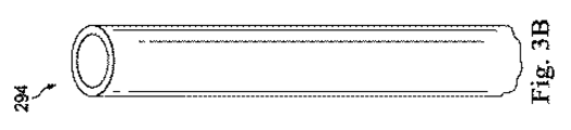
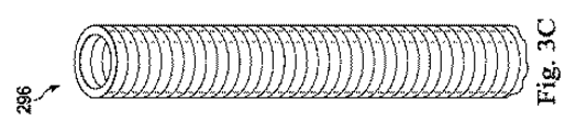
針235と関連する「フレキシブル」(“flexible”)という用語は、広く解釈されるべきである。本質的には、それは危害なく針を曲げ得ることを意味する。図3Aに示すような幾つかの実施態様において、フレキシブルな針290は、蛇のような構成における「椎骨」(“vertebrae”)に類似する一連の密接に離間する構成部品291を含んでよい。例えば、それらの両方の全文をここに参照として援用する、米国特許第6,817,974号及び米国特許出願公開第2013/0046317号を参照のこと。そのような構成において、各構成部品291は、運動学的連鎖内の短いリンクであり、各リンク間の可動な機械的拘束(例えば、ピンヒンジ、カップ及びボール、及び同等物)は、リンク間の相対的な動きの1つ(例えば、ピッチ)又は2つ(例えば、ピッチ及びヨー)の自由度(DOF)を許容することがある。他の実施態様において、針290は、図3Bに示すような閉塞した弾性的な(elastomeric)曲げられるチューブ294(例えば、ニチノール、ポリマ、及び同等物)又は図3Cに示すような開放した曲げられるチューブ296(例えば、切口切断チューブ(kerf-cut tube)、螺旋コイル、及び同等物)のように、連続的である。図3Cに示す実施態様において、チューブ296は、弾性的に(resiliently)フレキシブルなチューブ本体を形成するよう螺旋状の又はコイル状の構造に巻回されたフレキシブルな長さの材料を含む。例えば、チューブ296は、その全文をここに参照として援用する米国特許出願公開第2012/0123395号に記載するものに類似する構成を含んでよい。
The term “flexible” associated with the
フレキシブルな針290は、必須の引張特性及び曲げ特性をもたらす任意の適切な生体適合性材料で作られてよい。適切な材料は、非限定的な一例として、ニチノールのような形状記憶材料、ステンレス鋼、及びプラスチックを含んでよい。幾つかの実施態様において、フレキシブルな針290は、隅から隅まで同じ材料で作られる。他の実施態様において、フレキシブルな針290は、2つ又はそれよりも多くの異なる材料で作られてよい。幾つかの実施態様において、フレキシブルな針290は、生体適合性潤滑剤で被覆されてよい。
The
図4は、針235の遠位部分300を例示している。図2に関連して上述したように、針235は、フレキシブルな部分238と、剛的な部分240とを含む。フレキシブルな部分238は、剛的な部分240に対して近位にある。図示する実施態様において、フレキシブルな部分238は、管腔246を定める中空の連続的なフレキシブルなチューブを含む。上述のように、フレキシブルな部分238は、(図3Cに示すように)所望のコラム強さ(column strength)及び最小の軸方向圧縮との組み合わせにおいて針235に最大の可撓性(flexibility)を与えるコイル状の構造を含んでよい。管腔246は、針235の遠位端249で終端する。図示する実施態様において、フレキシブルな部分238は、受動的なフレキシブルであり、外力又は内力に応答して曲がるように構成される。他の実施態様において、フレキシブルな部分238は、能動的に操縦可能(例えば、図2に示すアクチュエータ210によって制御可能)であってよい。
FIG. 4 illustrates the
図示する実施態様において、剛的な部分240は、遠位先端245を含み、遠位先端245は、針235の切断要素245又はブレード245を含む。遠位先端245は、組織を通じる予測可能な湾曲経路及び針操縦を可能にしながら、組織を貫通し且つサンプリング(採取)するように構成される。図示する実施態様において、遠位先端245は、環状の非傾斜の部分的に円錐形のブレードを含む。傾斜ブレードと異なり、対称的な円錐形のブレードは、相対的な直線経路を維持しながら、組織を通じて芯除去(core)し得る。針235が組織を通じて前進させられると、組織は遠位端249にある孔302を通じて管腔246に進入し得る。
In the illustrated embodiment, the
剛的な部分240及びフレキシブルな部分238は、非限定的な一例として、接着、溶接(例えば、レーザ溶接)、及び/又は機械的締結具を含む、様々な既知の方法のいずれかによって、互いに固定的に取り付けられる。例えば、図示する実施態様において、フレキシブルな部分238の遠位端305は、接着剤接着によって剛的な部分240の近位端310に取り付けられる。しかしながら、幾つかの実施態様において、剛的な部分240は、フレキシブルな部分238に亘って延びて、近位部分238の長さに沿うより近位な場所で、フレキシブルな部分238に取り付けられ得る。幾つかの実施態様において、剛的な部分240は、フレキシブルな部分238の一体的な延長である。
図示する実施態様において、針235は、マーカ320a,320bを含む。マーカ320aは、遠位先端245に位置付けられ、マーカ320bは、剛的な部分240で遠位先端245に対して近位に位置付けられる。マーカ320a,320bは、挿入距離又は位置インジケータ(表示器)として機能し得る。幾つかの実施態様において、マーカ320a,320bは、放射線不透過性(例えば、蛍光透視マーカ)であってよい。マーカ320aは、リングマーカを含み、マーカ320bは、バンドマーカを含む。他の実施態様は、任意の数、種類及び構成の位置マーカを含んでよい。
In the illustrated embodiment, the
遠位先端245を含む剛的な部分240は、約1mm〜10mmに及ぶ長さL1を有する。例えば、1つの実施態様において、剛的な部分240は、約8mmの長さL1を有する。剛的な部分240の他の長さL1は、より長くてよく、或いはより短くてよい。遠位先端245は、約1〜8mmに及ぶ長さL2を有する。例えば、1つの実施態様において、剛的な部分240は、約4mmの長さL2を有する。遠位先端245の他の長さL2は、より長くてよく、或いはより短くてよい。上記寸法は例示的な目的のために提供されているに過ぎず、限定的であることを意図しない。他の寸法が想定される。
The
針235は、約1mm〜2.5mmに及ぶ外径D1を有する。例えば、1つの実施態様において、針235は、約1.5mmの外径を有する。他の針外径は、より長くてよく、或いはより短くてよい。幾つかの実施態様において、外径D1は、針235の(図2に示す)近位端248から遠位端249に先細り、近位端248での針外径D1は、遠位端249での針外径D1よりも大きい。幾つかの実施態様において、針外径D1は、針235の長さを通じて実質的に不変である。代替的な実施態様では、近位部分のより大きな外径D1と遠位部分300のより小さな外径との間に針235の急激な変化又は停止部(stop)があり得る。上記寸法は例示的な目的のために提供されているに過ぎず、限定的であることを意図しない。他の寸法が想定される。
針235は、約0.8mm〜1.4mmに及ぶ管腔内径D2を有する。内径D2は、組織の通過及び管腔246を通じる流れを可能にする大きさとされる。例えば、1つの実施態様において、針235は、約1mmの内径D2を有する。他の針内径は、より大きくてよく、或いはより小さくてよい。幾つかの実施態様において、内径D2は、針235の(図2に示す)近位端248から遠位端249に先細り、近位端248での内径D2は、遠位端249での内径よりも大きい。幾つかの実施態様において、内径D2は、針235の長さを通じて実質的に不変である。代替的な実施態様では、近位部分のより大きな内径D2と遠位部分300のより小さな内径との間に針235の急激な変化又は停止部があり得る。上記寸法は例示的な目的のために提供されているに過ぎず、限定的であることを意図しない。他の寸法が想定される。
図5は、図2に示す操縦可能なスタイレット260の斜視図を例示している。具体的には、図5は、スタイレット260の遠位部分360を例示している。図2を参照して上述するように、スタイレット260は、細長いフレキシブルな本体266と、操縦可能な部分268とを含む。図示する実施態様において、本体266はフレキシブルな本体に対して作用する力に応答して受動的に偏向するように構成され、操縦可能な部分268は、遠隔操作アセンブリ及び/又は(図2に示す)アクチュエータ210からの制御信号に応答して能動的に関節作動するように構成される。本体266は、作動ケーブル(例えば、作動ケーブル360)を操縦可能な部分268に運び且つ経路制御するように構成される。図示する実施態様において、本体266は、作動ケーブル360を操縦可能な部分268に誘導するよう1つに束ねられる多数の作動導管355を含む。図5及び6に示すように、本体266は、束ねられる導管355を取り囲む中実な壁を欠く。他の実施態様において、本体266は、導管355の束を取り囲むシースを含んでよい。
FIG. 5 illustrates a perspective view of the
スタイレット260は、0.8mm〜1.4mmに及ぶ外径D3を有する。例えば、1つの実施態様において、スタイレット260は、約1.0mmの外径を有する。他のスタイレット外径は、より多くてよく、或いはより小さくてよい。図示する実施態様において、(図2に示す)近位端での外径は、遠位端264での外径よりも大きい。幾つかの実施態様において、スタイレット260の外径D3は、針235の遠位先端245がスタイレット260の操縦可能な部分268をぴったり受けるように構成されるように、針235の遠位先端245の(図4に示す)内径に緊密に近似する。幾つかの実施態様において、内径D4は、内径D2と略等しい。幾つかの実施態様において、スタイレット260の外径D3は、スタイレット260が針235の管腔246内に受け入れられるときに、センサ要素270が(図4に示す)針235の長手軸NAと実質的に整列させられるように、針235の内径D2と緊密に近似する。幾つかの実施態様において、スタイレット260の外径D3は、スタイレット260が管腔246内に受け入れられるときに、スタイレット260が針235の管腔246を遮断するように、針235の内径D2と緊密に近似する。
The
具体的には、外径D3は、本体266の長さを通じて一定のままであり、操縦可能な部分268の長さL3の少なくとも部分に沿って遠位に先細る。代替的な実施態様において、スタイレット外径D3は、スタイレット260の長さに沿って異なる。代替的な実施態様では、スタイレット260の近位部分のより大きな外径と遠位部分350のより小さな外径との間にスタイレット260の急激な変化又は停止部があり得る。操縦可能な部分268の長さL3は、約2〜6mmに及び得る。例えば、1つの実施態様において、操縦可能な部分268は、約5mmの長さL3を有する。操縦可能な部分268の他の長さL3は、より大きくてよく、或いはより小さくてよい。上記寸法は例示的な目的のために提供されているに過ぎず、限定的であることを意図しない。他の寸法が想定される。
Specifically, the outer diameter D3 remains constant throughout the length of the
図6は、スタイレット260の本体266の斜視図及び部分断面図を例示している。図6に示すように、本体266の各導管355は、作動ケーブル360をスライド可能に受け入れるように構成されるフレキシブルなチューブを含む。図示する実施態様において、各導管355は、フレキシブルなマイクロコイル構造を含む。他の実施態様において、各導管355は、作動ケーブル360をスライド可能に受け入れるような大きさ及び構成とされる、あらゆる適切な種類の中空のフレキシブルな生体適合性チューブを含んでよい。図示する実施態様において、本体266は、センサ要素270を支持するように構成されるセンサ導管362の周りに円周状に配置される8つの導管355を含む。図示する実施態様において、各導管355は、導管355の間に(例えば、径方向に)間隙を残さないよう、隣接する導管355に直接隣接するセンサ導管362の周りに位置付けられる。1つの特徴において、センサ導管362は、センサ要素270の軸方向位置を(スタイレット260の長手軸LAに対して)1mmの範囲内に維持するような大きさ及び構成とされる。導管355及びセンサ導管362は、非限定的な一例として、接着、溶接(例えば、レーザ溶接)、及び/又は機械的締結具を含む、様々な既知の方法のうちの何れかによって、互いに固定的に取り付けられる。例えば、図示する実施態様において、導管355は、レーザ溶接によって、互いに並びにセンサ導管360に連結される。この構成はスタイレット260に所望の程度の軸方向剛性を与えることができ、小さなピッチを備え、軸方向圧縮は皆無であるか或いは僅かである。本体266は、所望の数の作動ケーブル360を操縦可能な部分268に正確に経路制御するように構成される、如何なる数及び配置の導管355を含んでもよい。例えば、図示する実施態様では、操縦可能な部分268は8つの作動ケーブル360を受け入れるように構成されるので、本体266は、各導管355が個々の作動ケーブル360を受け入れるように構成される、8つの導管355を含む。そのような実施態様において、作動ケーブルの牽引(pulling)又は作動は、スタイレット先端(即ち、操縦可能な部分268)の曲げに大いに寄与し、それはデバイス形状、位置、及び前進方向の制御性を向上させることがある。幾つかの他の実施態様は、作動ケーブルを収容する導管を欠いてよい。そのような実施態様において、作動ケーブルに張力をかける或いは引っ張ることは、スタイレット260全体に沿う分散される曲げをもたらすことがある。
FIG. 6 illustrates a perspective view and a partial cross-sectional view of the
図5及び6に示すように、本体266及び操縦可能な部分268は、非限定的な一例として、接着、溶接(例えば、レーザ溶接)、及び/又は機械的締結具を含む、様々な既知の方法のいずれかによって、互いに固定的に取り付けられる。例えば、図示する実施態様において、本体266の遠位端365は、レーザ溶接によって、操縦可能な部分268の近位端370に連結される。しかしながら、幾つかの実施態様において、近位端370は、本体266の遠位端355を越えて延びて、本体の長さに沿うより近位の場所で本体266に付着し得る。そのような実施態様において、本体266は、操縦可能な部分268内に小さな距離だけ延びてよい。幾つかの実施態様において、操縦可能な部分268は、本体266の一体的な延長である。
As shown in FIGS. 5 and 6, the
図2及び6に示すように、センサ要素270は、本体266の長手軸LAに沿って軸方向に延びる。図6に図示する実施態様において、センサ要素270は、センサ導管362内で本体266の中心を通じて延びる。他の実施態様では、センサ導管362を導管355に対して中心から外れた位置に位置付け得る。図示する実施態様において、センサ要素270は、スタイレット260の操縦可能な部分268内に少なくとも部分的に延びる。代替的な実施態様において、センサ要素270は、操縦可能な部分268に対して近位に、本体266で終端する。
As shown in FIGS. 2 and 6, the
針システム205が図1に示す遠隔操作医療システム100の医療器具システム104であるならば、センサ要素270はセンサシステム108の構成部品であってよい。針システム205が手動で操作されるならば或いは非ロボット処置のためにその他の方法において用いられるならば、センサ要素270は、センサ要素270に呼び掛け(interrogate)且つ受信するデータ(例えば、形状センサ要素からの形状データ)を処理するトラッキングシステムに連結されてよい。スタイレット260の具体的な操縦機構に拘わらず、針システム205の有用性は、センサ要素270を含むことによって強化される。センサ要素270が操縦可能な部分268内にどれぐらい遠く延びるかに依存して、センサ要素270は、スタイレット260の操縦可能な部分268の並びに/或いは針235及び/又はスタイレット本体266に沿う1つ又はそれよりも多くの別個の(離散的な)セグメントの位置、向き、速さ、姿勢、及び/又は形状を決定し得る。センサ要素270によって読まれるデータを、図1に示す制御システム112及び/又はセンサシステム108によって、使用可能な形状及び/又は位置情報に変換し得る。次に、形状及び/又は位置情報を用いて、スタイレット260(そして、結果的に、針235)の更なる操作を誘導し得る。
If the
図示する実施態様において、センサ要素270は、スタイレット260(及びスタイレット260が針235内に位置付けられるときには針235)の形状及び/又は位置測定値をもたらすセンサである。図示する実施態様において、センサ要素270は、地点局所化(即ち、位置/向き測定値)のために用い得るEMセンサシステムを含んでよい。幾つかの実施態様において、センサ要素270は、任意の所与の時間地点でスタイレット260の形状を決定するよう様々な時間間隔で累積的に測定される単一のEMセンサ又は多数のEMセンサを含む。EMセンサ要素270は、外的に生成される電場に晒されることがある1つ又はそれよりも多くの導電性コイルを含んでよい。その場合、EMセンサ要素270の各コイルは、外的に生成される電場に対するコイルの位置及び向きに依存する特性を有する誘導電気信号を生成する。1つの実施態様において、EMセンサシステムは、6つの自由度(「6DOF」)、例えば、3つの位置座標X、Y,Z、並びにベース地点のピッチ、ヨー、及びロールを示す3つの向き角度を測定するように、構成され且つ位置付けられてよい。代替的な実施態様において、EMセンサシステムは、5つの自由度(「5DOF」)、例えば、3つの位置座標X,Y,Z、並びにベース地点の2つの向きを測定するように、構成され且つ位置付けられてよい。例えば、幾つかの実施態様において、センサ要素270は、(例えば、使用者が、針235がスタイレット260と一緒に延ばされるときに、針先端249が患者内にある場所を認識するのを可能にするために)、スタイレット266の本体266に関する位置及び/又は向きデータを提供するように構成される5DOFのEMセンサを含む。EMセンサシステムの更なる記述は、その全文をここに参照として援用する、「Six-Degree of Freedom Tracking System Having a Passive Transponder on the Object Being Tracked」を開示する、1999年8月11日に出願された米国特許第6,380,732号に提供されている。
In the illustrated embodiment,
幾つかの実施態様において、センサ要素270は、スタイレット260と整列させられる光ファイバを含んでよい(例えば、光ファイバは、図6に示すように、センサ導管362内に設けられてよい)。センサ要素270の光ファイバは、針システム205の少なくとも部分の形状を決定するために光ファイバ曲げセンサを形成してよい。三次元内の光ファイバの相対的位置及び形状をモニタリングする様々なシステム及び方法が、それらの全文をここに参照として援用する、「Fiber optic position and shape sensing device and method relating thereto」を開示する2005年7月13日に出願された米国特許出願第11/180,389号、「Fiber-optic shape and relative position sensing」を開示する2004年7月16日に出願された米国仮特許出願第60/588,336号、「Optical Fiber Bend Sensor」を開示する1998年6月17日に出願された米国特許第6,389,187号に記載されている。他の代替では、レイリー散乱、ラマン散乱、ブリユアン散乱、及び蛍光散乱のような、他のひずみ感知技法を利用するセンサが、適切であることがある。他の代替的な実施態様では、針システム205の形状は、他の技法を用いて決定されてよい。
In some embodiments,
より具体的には、光ファイバを通じて進む光は、スタイレット260及び/又は針システム205の形状を検出するよう、並びに、その情報を利用して医療処置を支援するために、処理される。センサシステム(例えば、センサシステム108又は図2に記載するような他の種類のトラッキングシステム)は、スタイレット260の形状を決定するために用いられる光を生成し且つ検出する呼掛けシステム(interrogation system)を含んでよい。次いで、この情報を用いて、医療器具の部品の速度及び加速度のような、他の関連する変数を決定し得る。
More specifically, light traveling through the optical fiber is processed to detect the shape of the
上述のように、センサ要素270は、スタイレット260の長さに沿う形状測定値を提供する細長い光ファイバ形状センサを含んでよい。センサ要素270は、センサの長さ亘る単一の連続的な感知領域又はセンサの長さに沿って分散される多数の感知領域を含んでよい。別個の(離散的な)(discrete)位置センサと対照的に、細長いセンサは、単一のセンサを用いたスタイレット260の長さに沿う形状測定を可能にする。単一の細長い形状センサの統合的な性質は、スタイレット260のより正確な形状測定をもたらすことがあり、それはより精密な制御及び/又は強化された誤差補正を可能にして、スタイレット260(及び針235)が所望の手術軌跡を正確に横断するのを保証する。
As described above,
センサ要素270は例示的な目的のために単一の細長いセンサとして描写され且つ記載されているが、他の実施態様において、センサ要素270は、多数の別個の(離散的な)形状センサを含み得る。1つのそのような実施態様において、各形状センサは、スタイレット260の全長の連続的な部分の形状を測定することがある。多数の形状センサは、より大きな形状モデル化精度をもたらすことがあり、或いはセンサに影響を及ぼし得る環境要因(例えば、スタイレット260の長さに沿う温度変動)を補償するのに有用なことがある。
Although
図7A及び7Bは、本開示の1つの実施態様に従ったスタイレット260の操縦可能な部分268を例示している。スタイレット260は、低い軸方向剛性を有し且つ貫通し或いは穿刺するのに適さないカテーテル型デバイスと比べて、最小の軸方向圧縮又は座屈(buckling)で組織を貫通し或いは穿刺するのを可能にする、高い軸方向剛性及び先端形状(即ち、操縦可能な部分268の形状)を概ね有する。図7Aに描写する図示の実施態様において、操縦可能な部分268は、遠位端264に向かって先細るフレキシブルな関節付き構造を含む。操縦可能な部分268は、近位端400から遠位端264に延びる。図示の実施態様において、操縦可能な部分268は、近位の曲げられる区画410と、遠位の曲げに抗する区画415とを含む。図示の実施態様において、曲げられる区画410は、複数の関節作動可能なセグメント、即ち、近位セグメント417、中間セグメント418、及び遠位セグメント419を含む、連続的な関節付き構造を含む。近位関節ピボット420(近位関節枢軸)が、近位セグメント417及び中間セグメント418を分離し、遠位関節ピボット425(遠位関節枢軸)が、中間セグメント418及び遠位セグメント419を分離する。図7に示す曲げられる区画410は、例示的であるに過ぎず、限定的であることを意図しない。この開示に鑑みれば、曲げられる区画410は、作動ケーブル360を収容し且つ作動ケーブル360の作動後に多数の方向において曲がるように構成される、あらゆる種類の操縦可能な、概ね管状の構造を含んでよい。換言すれば、スタイレット260の操縦可能な部分268は、操縦可能なスタイレット260の所要の機能性をもたらすために必要とされる、任意の数のセグメントを有する少なくとも1つの曲げられる区画から如何なる数の曲げられる区画まで含んでよい。幾つかの場合には、スタイレット260の操縦可能な部分268は、2004年9月24日に出願された「Articulating mechanism with flex-hinged links」という名称の米国特許出願公開第2005/0273085号、及び/又は2011年8月15日に出願された「Medical instrument with flexible wrist mechanism」という名称の米国特許出願公開第2013/0046317号に開示される構成部品又は構成と類似の構成部品又は構成を含み、それらの両方の全文をここに参照として援用する。
7A and 7B illustrate the
操縦可能な部分268は、所要の引張特性及び曲げ特性をもたらす、いずれの適切な生体適合性材料で作られてもよい。適切な材料は、非限定的な一例として、ポリマ、ニチノールのような形状記憶材料、ステンレス鋼、及びプラスチックを含んでよい。幾つかの実施態様において、操縦可能な部分268は、隅から隅まで同じ材料で作られる。他の実施態様において、操縦可能な部分268は、2つ又はそれよりも多くの異なる材料で作られてよい。例えば、幾つかの実施態様において、曲げに抗する区画415は、曲げられる区画410よりも剛的な材料で形成されてよい。幾つかの実施態様において、操縦可能な部分268は、生体適合性潤滑剤で被覆されてよい。
The
曲げられる区画410及び曲げに抗する区画415は、非限定的な一例として、接着、溶接(例えば、レーザ溶接)、及び/又は機械的締結具を含む、様々な既知の方法のいずれかによって、互いに固定的に取り付けられる。例えば、図示する実施態様において、曲げられる区画410の遠位セグメント419及び曲げに抗する区画415は、レーザ溶接によって互いに連結される。他の実施態様において、曲げられる区画410と曲げに抗する区画415は、単一の一体の細長いチューブ又は中実な部材で形成されてよく、それらは、本発明に従って切られて、3つのセグメント417,418,419、近位関節ピボット420、並びに曲げられる区画410及び曲げに抗する区画415の近位関節ピボット420及び遠位関節ピボット420を形成してよい。
The
曲げに抗する区画415は、スタイレット260の遠位先端を形成し、最小の軸方向圧縮を伴って組織を貫通するように形作られ且つ構成される。図示する実施態様において、曲げに抗する区画415は、円錐形の鋭利な先端を形成する。他の実施態様において、曲げに抗する区画415は、それが最小の軸方向圧縮を伴って組織を貫通するのを可能にする、如何なる形状を有してもよい。曲げに抗する区画415は、作動ケーブル360を受け且つ固定する(anchor)ように構成される。図示する実施態様において、曲げに抗する区画415は、作動ケーブル360の遠位端435を受け且つ/或いは固定する溝又は圧痕430(indentations)を含む。図示する実施態様において、スタイレット260は、8つの作動ワイヤ360を含み、曲げに抗する区画415は、作動ワイヤ360の各々を受ける8つの相補的な溝430を含む。他の実施態様において、曲げに抗する区画415は、スタイレット260に含められる作動ワイヤ360の数に適合する、あらゆる数の溝430を含んでよい。図示する実施態様において、溝430は、曲げに抗する区画415の周りに対称的に及び円周状に配置される。他の実施態様において、溝430は、スタイレット260の所望の操縦性を可能にする、あらゆる仕方において、曲げに抗する区画415について配置されてよい。
The bend
上述のように、操縦可能な部分268(そして、具体的には、曲げられる区画410)は、遠隔操作アセンブリ及び/又は(図2に示す)作動アクチュエータ210からの制御信号に応答する個々の作動ケーブル360の選択的な作動後に能動的に関節作動するように構成される。図7Aに示すように、各作動ケーブル360は、溝430内で終端する前に、フレキシブルな部分266から操縦可能な部分268にある個々の通路440内に並びに操縦可能な部分268にある個々の通路440を通じて延びる。図示する実施態様では、4つの作動ケーブル360a,360b,360c,360dが示されている。例えば、図示する実施態様は、4つの相補的な溝内に固定された、作動ワイヤ360a,360b,360c,360dの遠位端435a,435b,435c,435dをそれぞれ示している。
As described above, the steerable portion 268 (and, in particular, the
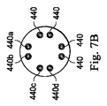
図示する実施態様において、作動ケーブル360は、スタイレット260の長手軸LAについてペア(対)で配置されている。具体的には、図7Aに示すように、作動ケーブル360a及び作動ケーブル360bは、通路440a及び440bを通じて延びるペアを形成する。1つの実施態様において、作動ケーブル360a及び360bは、同じ連続的なケーブルの2つの枝であり、2つの枝360a,360bは、近位端で一緒に作動させられる。図7Bは、(図2に示すような)操縦可能な部分268のセグメント217の断面図を例示している。図7Bに示すように、通路440は、操縦可能な部分268の長手軸LAについて対称的に配置される、4つのペアにグループ分けされる。例えば、通路440aは、通路440bとペアにされ、通路440cは、通路440dとペアにされる。よって、作動ケーブル360aは、作動ケーブル360bとペアにされ、作動ケーブル360cは、作動ケーブル360dとペアにされる。他の実施態様において、通路440(そして、結果的に、作動ケーブル360)は、スタイレット260の所望の操縦性を可能にする、あらゆる仕方において、曲げられる区画410について配置されてよい。
In the illustrated embodiment, the
張力及び/又は伸張力を加えて、スタイレット260の操縦可能な部分268の所望の曲げを引き起こし得る。機械的テンショナ、モータアクチュエータ、又は(例えば、スタイレット260に連結される)いずれかの他の機構を介して、作動ケーブル360を制御し得る。例えば、幾つかの実施態様において、作動ケーブル360は、(Dunlop et al.による「A Nitinol Wire Actuated Stewart Platform」(その全文をここに参照として援用するProc. 2002 Australasian Conference on Robotics and Automation, Nov. 27-29, 2002)に記載されるような)電流誘導加熱に応答して縮むように構成される(複数の)ニチノールワイヤのような、温度変化に応答する材料を含み得る。様々な他の操縦機構が直ちに明らかである。例えば、幾つかの実施態様において、各作動ケーブル360は、複数の作動導管のうちの1つを通じて通路440内に延び、そして、複数の作動導管のうちの他のものを通じて戻ってよい。
Tension and / or stretching forces can be applied to cause the desired bending of the
図7Aにおいて、操縦可能な部分268は、例示的なx軸と平行に整列する長手軸LAを備える直線的な又は曲げられていない状態において示されている。図8A及び8Bは、曲げられた状態における操縦可能な部分268を例示している。図8Aでは、作動ケーブル360c及び360dは、張力をかけられた状態にあるので、操縦可能な部分268は、近位関節ピボット420で、例示的なx−z平面において通路440c及び440dの方向に向かって(例えば、ピッチ運動において)曲がる。具体的には、近位関節ピボット420に対して遠位の操縦可能な部分268の部分(即ち、セグメント418、セグメント419、及び曲げに抗する区画415)は、張力をかけられるケーブル360c及び360dをそれぞれ支持する通路440c及び440dの方向において曲がり或いは関節作動する。図18Bでは、作動ケーブル360a及び360bも(即ち、作動ケーブル360c及び360dに加えて)張力をかけられた状態にあるので、操縦可能な部分268は、遠位関節ピボット425でも、例示的なx−y平面において通路440a及び440bの方向に向かって曲がる。具体的には、遠位関節ピボット425に対して遠位の操縦可能な部分268の部分(即ち、セグメント419及び曲げに抗する区画415)は、張力をかけられるケーブル360a及び360bをそれぞれ支持する通路440a及び440bの方向において曲がり或いは関節作動する。
In FIG. 7A,
図9は、本開示の1つの実施態様に従った針システム500の斜視図を例示している。針システム500は、図2に示す針システム205と類似してよい。具体的には、図9は、本開示に従った図4に示す例示的な針内に位置付けられ且つ針から延びる、図5に示す例示的なセンサスタイレットを例示している。針システム500は、針235の管腔246内にスライド可能に位置付けられるスタイレット260を含む。スタイレット260及び針235は、互いに入れ子式に配置される。よって、スタイレット260は、針235の管腔246内に完全に引っ込むことができ、図9に示すように、(即ち、針235が静止的なままである間に)針235から遠位に延びることもできる。
FIG. 9 illustrates a perspective view of a
図9に図示するように、スタイレット260は、針235の内側に受け入れられるような形状及び大きさにされる。具体的には、スタイレット260の操縦可能な部分268は、針235の剛的な部分240の内側にぴったり受け入れられるような形状及び大きさにされる。図示する実施態様において、針235の内径D2は、スタイレット260の外径D3よりも僅かに大きいだけの大きさにされ、それにより、スタイレット260が針235から出現するときに、スタイレット260が針235の剛的な部分240内に確実に支持されるのを可能にする。
As shown in FIG. 9, the
幾つかの実施態様において、図1に示す遠隔操作医療システム100は、スタイレット260の操縦可能な部分268の動き又は関節作動を制御するように構成される。具体的には、懸隔操作システム100は、作動ケーブル360の作動を制御することができ、それにより、スタイレット260の操縦可能な部分268の動き又は曲げを制御することができる。操縦可能な部分268が操縦され或いは動かされるときに、操縦可能な部分268が(図9に示すように)針235内に位置付けられるならば、針235は、(例えば、針235がスタイレット260の可動部分を覆い且つ取り囲むので)、操縦可能な部分268の動きを真似て、操縦可能な部分268と一致して動く。幾つかの実施態様において、遠隔操作システム100及び針システム500は、操縦可能な部分268を所定のセット(組)の形状又は曲げ角度にシフトさせるように構成される。例えば、幾つかの実施態様において、操縦可能な部分268は、単一の命令を遠隔操作システム100に入力することによって、図8Aに示すように近位関節ピボット420で事前設定角度α1を有する、「左向き曲げ」を備える、所定の第1の位置を有してよい。他の実施態様において、操縦可能な部分268は操作され且つ動かされて、ある範囲の曲げ角度を有する1つ又はそれよりも多くの関節ピボットを包含する様々な曲げ形状になってよい。
In some embodiments, the teleoperated
図11−12は、本開示の1つの実施態様に従って生検サンプルを得るために患者解剖学的構造Pを進んでいる、図9に示す例示的な針システム500の概略図を例示している。図10は、本開示の実施態様に従って針235内に引っ込められた或いは覆われた状態におけるスタイレット260を備える、曲がりくねった経路510(即ち、患者解剖学的構造内の通路)を進んでいる針システム500の概略図である。図示する実施態様において、針システム500は、標的領域515に向かってフレキシブルなシース520を通じて前進して示されている。フレキシブルなシース520は、図2に関して上述したフレキシブルなシース225と同じであってよい。図示する実施態様において、針235は、フレキシブルなシース520内にスライド可能に受け入れられ、スタイレット260は、針235内にスライド可能に受け入れられている。針235はフレキシブルなシース520を通じて前進させられるが、スタイレット260は、針235の管腔246内で引っ込められた或いは非延出の状態にある。具体的には、スタイレット260の遠位端264は、針235の遠位端249に対して近位に位置付けられている。フレキシブルなシース520を通じる針システム500の前進中、使用者は、スタイレット260を備えるセンサ要素270を利用する必要はないが、使用者は、フレキシブルなシース520を通じる針システム500の正確な進行を確認するために、そうしてよい。
FIGS. 11-12 illustrate a schematic diagram of the
図11は、本開示の実施態様に従った標的領域515に向かって進む針システム500の概略図を例示している。具体的には、図11は、標的領域515の方向において組織を貫通するよう針235から出現しているスタイレット260を例示している。使用者が、処置を通じて、針235をフレキシブルなシース520から前進させると、使用者は、放射線不透過性マーカ320a(又は、図示しない、他の放射線不透過性マーカ)と協働して蛍光透視法又は他の映像法を利用して、(例えば、標的領域515に対する)患者解剖学的構造内の針235の位置をトラッキング(追跡)してよい。針235及びスタイレット260をフレキシブルなシース520から前進させた後に(即ち、スタイレット260が針235内に位置付けられた状態で)、使用者は、スタイレット260を針235から前進させて、(例えば、組織を芯除去(コアイング)(coring)せずに、そして、針235の管腔246が組織を受け入れるのを遮断しながら)針235の前方にある組織を貫通することができる。センサスタイレット260が前進させられると、使用者はセンサ要素270から受信するデータを利用して、スタイレット260の位置、向き、及び進行を評価し且つトラッキングしてよい。
FIG. 11 illustrates a schematic diagram of a
センサ要素270から得られる情報を様々な方法において用い得る。例えば、測定される形状から、組織内への全挿入深さ並びに先端位置及び向き(例えば、スタイレット260の遠位端264)を決定し得る。制御入力に対する近位挿入量及び回転量のみを測定して、先端への完全な移動(perfect transfer)を推定する代わりに、これらの変数をサーボループにおいて用いて、スタイレット260及び針235の挿入及び向きを精密に制御し得るし、センサ要素270を用いて、針235又はスタイレット260のねじれ及び軸方向可撓性(torsional and axial flexibility)並びに針235又はスタイレット260と組織との間の摩擦及び法線力の影響と無関係に、遠位挿入及び回転を直接的に測定し得る。他の実施態様では、現在のスタイレット位置から標的領域515への実現可能な経路を計算するアルゴリズムを計画することにおいて、(形状情報から計算されるような)測定される先端位置及び向きを用い得る。センサ要素270を用いて、(潜在的に不正確な)撮像技法の代わりに或いはそれらに加えて、センサスタイレット姿勢及び針姿勢を測定し得る。
Information obtained from
他の実施態様では、術前データに対する針235及び/又はスタイレット260の位置合わせ(registration)を向上させるために、撮像技法と共にセンサ要素270を用い得る。例えば、撮像可能な基準構成をセンサ要素270の部分に取り付けることによって、或いはセンサ要素270上の固定的な基準地点を患者にある視覚的な基準構成に結合させることによって、センサスタイレット270及び/又はセンサ要素270のベース或いは何らかの他の部分を画像座標空間と位置合わせし得る。術中撮像は、組織運動又は変形に応答してスタイレット及び針軌跡を適合させる手段をもたらす。解剖学的標的に対するその位置/向きを測定し得るように、スタイレット260及び/又は針235の測定される形状を用いて、術中画像内でスタイレット260及び/又は針235を検出し且つ局所化するのを支援し得る。
In other embodiments,
スタイレット260のセンサ要素270からの感知データ及び引き続きの判定に基づき、使用者及び/又は遠隔操作システム100は、(例えば、図5に示す特定の作動ケーブル360に選択的に張力をかけ或いは特定の作動ケーブル360を選択的に緩めて、図8A及び8Bに示すように、操縦可能な部分268の特定の区画を曲げることによって)、スタイレット260の操縦可能な部分268を標的領域515に向かって選択的に操縦し得る。具体的には、スタイレット260のセンサ要素270を駆動機構と共に用いて、医療処置中にスタイレット260の操縦可能な部分268を操縦するアクチュエータを(例えば、使用者によって)手動で或いは(例えば、遠隔操作システム100によって)自動的に制御するための入力をもたらし得る。
Based on the sensing data from the
使用者がスタイレット260を組織内に前進させるときに或いは前進させた後で、使用者は針235を遠位に前進させて、針235をスタイレット260の上にスライドさせてよい。図12は、スタイレット260の操縦可能な部分268の上に延びて、(そして、スタイレット260の曲率に従って)、(例えば、標的領域515から生検サンプルを得る或いは吸引するために)標的領域515を貫通する、針2356の剛的な部分240を例示している。スタイレット260が標的領域515に(或いはより大きな標的領域515内の別個の(離散的な)関心の領域にさえ)精密に進められると、スタイレット260は、針235の僅かに前方に前進させられて、針235が組織を通じてスタイレット260の上を前進するときに針235の軌跡を誘導する。
When or after the user advances
使用者が(例えば、センサ要素270からのX線写真データ及び/又は感知データを用いて)標的領域内の針235の正確な位置付けを確認した後に、使用者は、図13に示すように、スタイレット260を近位に引き、標的領域515を通じる吸引及び/又は芯除去を開始して、組織サンプル(例えば、生検サンプル)を得てよい。幾つかの実施態様において、針システム500は、標的領域515の生検サンプルを針管腔246内に吸引する。他の実施態様において、針システム500は、標的領域515の生検サンプルを針235の剛的な部分内に芯除去する。
After the user confirms the correct positioning of the
図14は、スタイレット260を用いる或いは制御する方法の1つの実施態様をフローチャート600において例示している。ステップ605で、針システム500(例えば、スタイレット260及び針235)は、図10に示すように、関心の領域又は標的組織(例えば、図10に示す標的領域515)の方向において、患者解剖学的構造(例えば、図10に示す患者解剖学的構造P)内に一緒に前進させられてよい。幾つかの実施態様において、スタイレット260及び針235は、給送デバイス(例えば、図10に示すフレキシブルなシース520)内で前進させられてよい。スタイレット260及び針235が関心の領域に向かって前進させられるとき、スタイレット260は針235内に入れ子式に覆われてよい。
FIG. 14 illustrates one embodiment of a method of using or controlling
ステップ610で、関心の領域に向かう針システム500の前進中、スタイレット260のセンサ要素270が利用される必要はないが、制御システム(例えば、制御システム112のプロセッサ)は、センサ要素270によって供給される形状及び/又は位置データを解析して、患者解剖学的構造を通じる針システム500の正確な進行を確認してよい。
At
ステップ615で、針システム500が関心の領域の近傍に位置付けられた後に、スタイレット260は(例えば、針235の遠位端249を越えて)針235の前方に前進させられて、図11に示すように、組織を貫通してよい。スタイレット260は、組織を芯除去せずに組織を貫通して、組織を通じる針235の後の進行を容易化してよい。
After the
ステップ620で、センサ要素270は、センサ要素270が組織内に前進させられるときに、スタイレット260の現在の形状/位置を取得し或いは検出することができ、制御システム112は、センサ要素270によって供給される形状及び/又は位置データを解析して、関心の領域に対する針システム500の位置を決定してよい。
At
ステップ625で、制御システム112は、センサ要素270によって供給される形状及び/又は位置データに基づき、スタイレット260を関心の領域に向かって操縦してよい。
At
ステップ630で、制御システム112は、図12に示すように、針235をスタイレット260の上に或いは関心の領域内に前進させてよい。
At
ステップ635で、スタイレット260は、図13に示すように、針235を通じて引かれてよい。
At
ステップ640で、針235は、関心の領域内に更に前進させられて、組織を通じて芯除去し且つ生検サンプルを得てよい。
At
本発明の実施態様における1つ又はそれよりも多くの要素は、制御システム112のようなコンピュータシステムのプロセッサ上で実行するソフトウェア内で実施されてよい。ソフトウェア内で実施されるとき、本発明の実施態様の要素は、本質的には、必要なタスクを遂行するコードセグメントである。通信媒体又は通信リンクを通じて搬送波において具現されるコンピュータデータ信号によってダウンロードされてよいプログラム又はコードセグメントをプロセッサ可読記憶媒体又はデバイス内に格納し得る。プロセッサ可読記憶デバイスは、光媒体、半導体媒体、及び磁気媒体を含む、情報を格納し得る、あらゆる媒体を含んでよい。プロセッサ可読格納デバイスの実施例は、電子回路、半導体デバイス、半導体メモリデバイス、読出し専用記憶装置、フラッシュメモリ、消去可能なプログラム可能読取り専用記憶装置(EPROM)、フロッピーディスケット、CD−ROM、光ディスク、ハードディスク、又は他の記憶デバイスを含む。コードセグメントは、インターネット、イントラネット等のような、ネットワークを介してダウンロードされてよい。
One or more elements in an embodiment of the present invention may be implemented in software executing on a processor of a computer system, such as
提示するプロセス及び表示は、本来的に、如何なる特定のコンピュータ又は他の装置にも関連付けられないことに留意のこと。様々なこれらのシステムのための所要の構造は、請求項中に要素として現れる。加えて、本発明の実施態様は、如何なる特定のプログラミング言語をも参照して記載されていない。様々なプログラミング言語は、ここに記載するような本発明の教示を実施するために用いられてよいことが理解されるであろう。 Note that the process and display presented are not inherently associated with any particular computer or other device. The required structure for a variety of these systems will appear as elements in the claims. In addition, embodiments of the present invention are not described with reference to any particular programming language. It will be appreciated that a variety of programming languages may be used to implement the teachings of the invention as described herein.
本発明の特定の例示的な実施態様を記載し且つ添付の図面中に示したが、そのような実施態様は例示的であるに過ぎず、広い発明を限定しないこと、並びに、本発明の実施態様は、図示し且つ記載する特定の構造及び配置に限定されないことが理解されるべきである。何故ならば、様々な他の変更が当業者の心に思い浮かぶことがあるからである。 While specific exemplary embodiments of the invention have been described and illustrated in the accompanying drawings, such embodiments are merely exemplary and are not intended to limit the broad invention and to practice the invention. It is to be understood that the embodiments are not limited to the specific structures and arrangements shown and described. This is because various other modifications may occur to those skilled in the art.
Claims (33)
フレキシブルな近位部分と、
剛的な遠位部分と、
前記フレキシブルな部分及び前記剛的な遠位部分を通じて前記近位端から前記遠位端に延び且つ前記器具の長手軸を定める管腔とを含み、
前記フレキシブルな部分は、前記剛的な遠位部分に固定的に連結される、
細長い器具と、
前記細長い器具の前記管腔内にスライド可能に配置されるスタイレットであって、
操縦可能な部分に固定的に連結されるフレキシブルな本体と、該フレキシブルな本体を通じて延びるセンサ要素とを含み、前記操縦可能な部分が前記細長い器具内に引っ込められる引込状態と、前記操縦可能な部分が前記細長い器具の前記剛的な遠位部分から少なくとも部分的に延出する延出構成との間で、前記細長い器具内で移動可能である、
スタイレットとを含む、
最小侵襲的システム。 An elongated instrument extending from the proximal end to the distal end,
A flexible proximal portion;
A rigid distal portion;
A lumen extending from the proximal end to the distal end through the flexible portion and the rigid distal portion and defining a longitudinal axis of the instrument;
The flexible portion is fixedly coupled to the rigid distal portion;
An elongated instrument,
A stylet slidably disposed within the lumen of the elongated instrument,
A retractable state wherein the steerable portion includes a flexible body fixedly coupled to the steerable portion and a sensor element extending through the flexible body, the steerable portion being retracted into the elongated instrument; Is movable within the elongate instrument between an extended configuration extending at least partially from the rigid distal portion of the elongate instrument;
Including stylets,
Minimally invasive system.
近位端から遠位端に延び且つ前記器具の長手軸を定める管腔を含む針と、
前記細長い器具の前記管腔内にスライド可能に配置されるスタイレットであって、近位のフレキシブルな本体と、曲げに抗する先端を含む遠位の操縦可能な部分と、前記フレキシブルな本体を通じて延びるセンサ要素とを含み、前記操縦可能な部分が前記針の前記管腔内に引っ込められる引込状態と、前記医療器具の前記操縦可能な部分が前記針の前記遠位端から少なくとも部分的に延出する延出構成との間で、前記針内で移動可能である、スタイレットと、
前記アクチュエータから前記スタイレットの前記フレキシブルな本体を通じて延び且つ前記スタイレットの前記操縦可能な部分内で終端する複数の作動ケーブルとを含む、
最小侵襲的システム。 An actuator,
A needle including a lumen extending from a proximal end to a distal end and defining a longitudinal axis of the instrument;
A stylet slidably disposed within the lumen of the elongate instrument, wherein the proximal flexible body, a distal steerable portion including a bending resistant tip, and through the flexible body A retractable state in which the steerable portion is retracted into the lumen of the needle, and the steerable portion of the medical device extends at least partially from the distal end of the needle. A stylet that is movable within the needle between an extending configuration to exit;
A plurality of actuation cables extending from the actuator through the flexible body of the stylet and terminating in the steerable portion of the stylet;
Minimally invasive system.
針システムを患者内で標的領域に向かって前進させるステップであって、前記針システムは、細長い医療器具の管腔内にスライド可能に位置付けられるスタイレットを含み、該スタイレットは、フレキシブルな本体と、遠位の操縦可能な部分と、該スタイレットの特性を検出するように構成されるセンサ要素とを含む、ステップと、
前記スタイレットの前記操縦可能な部分を前記細長い医療器具の遠位端に対して遠位に前進させるステップと、
前記スタイレットが前記標的領域に向かって前進するときに前記センサ要素から前記スタイレットの特性を取得するステップと、
該取得する特性に基づき前記標的領域に対する前記スタイレット及び前記細長い医療器具の位置を決定するステップと、
該決定する位置に基づき前記スタイレットの前記操縦可能な部分を前記標的領域に向かって進めるステップと、
前記細長い医療器具を前記スタイレットの上で前記標的内に進めるステップとを含む、
方法。 A method for assessing a target area in a patient comprising:
Advancing a needle system in a patient toward a target region, the needle system including a stylet slidably positioned within the lumen of an elongated medical device, the stylet comprising a flexible body and Including a distal steerable portion and a sensor element configured to detect a property of the stylet;
Advancing the steerable portion of the stylet distally with respect to the distal end of the elongated medical device;
Obtaining a property of the stylet from the sensor element as the stylet advances toward the target area;
Determining the position of the stylet and the elongate medical device relative to the target area based on the acquired characteristics;
Advancing the steerable portion of the stylet toward the target area based on the determined position;
Advancing the elongate medical device over the stylet and into the target;
Method.
前記標的領域から前記細長い器具の前記管腔内に生検を得るステップとを更に含む、
請求項30に記載の方法。 Pulling the stylet from the lumen of the elongated medical device;
Obtaining a biopsy from the target area into the lumen of the elongated instrument;
The method of claim 30.
Applications Claiming Priority (3)
| Application Number | Priority Date | Filing Date | Title |
|---|---|---|---|
| US201461974113P | 2014-04-02 | 2014-04-02 | |
| US61/974,113 | 2014-04-02 | ||
| PCT/US2015/022006 WO2015153174A1 (en) | 2014-04-02 | 2015-03-23 | Devices, systems, and methods using a steerable stylet and flexible needle |
Related Child Applications (1)
| Application Number | Title | Priority Date | Filing Date |
|---|---|---|---|
| JP2019219607A Division JP6816243B2 (en) | 2014-04-02 | 2019-12-04 | Stylet and minimally invasive system |
Publications (3)
| Publication Number | Publication Date |
|---|---|
| JP2017511187A true JP2017511187A (en) | 2017-04-20 |
| JP2017511187A5 JP2017511187A5 (en) | 2018-04-26 |
| JP6629230B2 JP6629230B2 (en) | 2020-01-15 |
Family
ID=54241106
Family Applications (2)
| Application Number | Title | Priority Date | Filing Date |
|---|---|---|---|
| JP2016560463A Active JP6629230B2 (en) | 2014-04-02 | 2015-03-23 | Minimal invasive system |
| JP2019219607A Active JP6816243B2 (en) | 2014-04-02 | 2019-12-04 | Stylet and minimally invasive system |
Family Applications After (1)
| Application Number | Title | Priority Date | Filing Date |
|---|---|---|---|
| JP2019219607A Active JP6816243B2 (en) | 2014-04-02 | 2019-12-04 | Stylet and minimally invasive system |
Country Status (6)
| Country | Link |
|---|---|
| US (2) | US10779803B2 (en) |
| EP (1) | EP3125983B1 (en) |
| JP (2) | JP6629230B2 (en) |
| KR (1) | KR102337419B1 (en) |
| CN (2) | CN110833382B (en) |
| WO (1) | WO2015153174A1 (en) |
Cited By (2)
| Publication number | Priority date | Publication date | Assignee | Title |
|---|---|---|---|---|
| WO2019163906A1 (en) * | 2018-02-21 | 2019-08-29 | オリンパス株式会社 | Medical system and operation method of medical system |
| JP7404356B2 (en) | 2018-10-04 | 2023-12-25 | バイオセンス・ウエブスター・(イスラエル)・リミテッド | Ductile suction device |
Families Citing this family (76)
| Publication number | Priority date | Publication date | Assignee | Title |
|---|---|---|---|---|
| US9232959B2 (en) | 2007-01-02 | 2016-01-12 | Aquabeam, Llc | Multi fluid tissue resection methods and devices |
| US8814921B2 (en) | 2008-03-06 | 2014-08-26 | Aquabeam Llc | Tissue ablation and cautery with optical energy carried in fluid stream |
| US20120191086A1 (en) | 2011-01-20 | 2012-07-26 | Hansen Medical, Inc. | System and method for endoluminal and translumenal therapy |
| CN108606773B (en) | 2012-02-29 | 2020-08-11 | 普罗赛普特生物机器人公司 | Automated image-guided tissue ablation and treatment |
| US10231867B2 (en) | 2013-01-18 | 2019-03-19 | Auris Health, Inc. | Method, apparatus and system for a water jet |
| US10744035B2 (en) | 2013-06-11 | 2020-08-18 | Auris Health, Inc. | Methods for robotic assisted cataract surgery |
| US10426661B2 (en) | 2013-08-13 | 2019-10-01 | Auris Health, Inc. | Method and apparatus for laser assisted cataract surgery |
| CN110833382B (en) * | 2014-04-02 | 2023-05-30 | 直观外科手术操作公司 | Devices, systems, and methods using steerable stylet and flexible needle |
| US20160287279A1 (en) | 2015-04-01 | 2016-10-06 | Auris Surgical Robotics, Inc. | Microsurgical tool for robotic applications |
| WO2016187056A1 (en) * | 2015-05-15 | 2016-11-24 | The Johns Hopkins University | Manipulator device and therapeutic and diagnostic methods |
| JP6476293B2 (en) * | 2015-06-12 | 2019-02-27 | オリンパス株式会社 | Flexible tube insertion device |
| EP3326764A4 (en) * | 2015-07-17 | 2019-03-13 | Olympus Corporation | Manipulator |
| US10575754B2 (en) | 2015-09-23 | 2020-03-03 | Covidien Lp | Catheter having a sensor and an extended working channel |
| US9955986B2 (en) | 2015-10-30 | 2018-05-01 | Auris Surgical Robotics, Inc. | Basket apparatus |
| US10639108B2 (en) | 2015-10-30 | 2020-05-05 | Auris Health, Inc. | Process for percutaneous operations |
| US9949749B2 (en) | 2015-10-30 | 2018-04-24 | Auris Surgical Robotics, Inc. | Object capture with a basket |
| DE112016005402T5 (en) * | 2015-11-25 | 2018-08-09 | Spiration, Inc. | SLEEVES FOR NEEDLE INTRODUCTION |
| EP3216415A1 (en) * | 2016-03-07 | 2017-09-13 | Deutsches Krebsforschungszentrum Stiftung des Öffentlichen Rechts | A system for navigated punction, biopsy or ablation comprising a needle-like instrument and a removable sensor carrier |
| US10825177B2 (en) * | 2016-05-16 | 2020-11-03 | TrackX Technology, LLC | Imaging system and method for image localization of effecters during a medical procedure |
| AU2017268213B2 (en) * | 2016-05-16 | 2021-03-04 | TrackX Technology, LLC | System and method for image localization of effecters during a medical procedure |
| KR102598706B1 (en) * | 2016-05-31 | 2023-11-07 | 인튜어티브 서지컬 오퍼레이션즈 인코포레이티드 | Flexible biopsy needle system |
| US11344376B2 (en) | 2016-07-01 | 2022-05-31 | Intuitive Surgical Operations, Inc. | Systems and methods for flexible computer-assisted instrument control |
| US10682192B2 (en) * | 2016-09-30 | 2020-06-16 | Intuitive Surgical Operations, Inc. | Variable-length guide apparatus for delivery of a flexible instrument and methods of use |
| CN110177507A (en) * | 2016-10-05 | 2019-08-27 | 宾夕法尼亚大学理事会 | That sharply turns turns to needle |
| EP3525696A4 (en) * | 2016-10-12 | 2020-04-08 | Intuitive Surgical Operations Inc. | Surgical puncture device insertion systems and related methods |
| US11529190B2 (en) | 2017-01-30 | 2022-12-20 | Covidien Lp | Enhanced ablation and visualization techniques for percutaneous surgical procedures |
| EP3528710A1 (en) * | 2017-02-28 | 2019-08-28 | Boston Scientific Scimed, Inc. | Articulating needles |
| JP2020512169A (en) * | 2017-03-24 | 2020-04-23 | ロバート ジェイ.コットーネRobert J. COTTONE | System and method for tissue displacement |
| US10792466B2 (en) | 2017-03-28 | 2020-10-06 | Auris Health, Inc. | Shaft actuating handle |
| WO2018187244A2 (en) * | 2017-04-03 | 2018-10-11 | Broncus Medical Inc. | Electrosurgical access sheath |
| EP4032459A1 (en) | 2017-04-07 | 2022-07-27 | Auris Health, Inc. | Patient introducer alignment |
| US10285574B2 (en) | 2017-04-07 | 2019-05-14 | Auris Health, Inc. | Superelastic medical instrument |
| IT201700042116A1 (en) * | 2017-04-14 | 2018-10-14 | Medical Microinstruments Spa | ROBOTIC ASSEMBLY FOR SURGERY |
| CN106943183B (en) * | 2017-04-26 | 2023-09-08 | 郑明辉 | Minimally invasive flexible puncture tube and minimally invasive channel puncture assembly |
| EP3651695B1 (en) * | 2017-07-13 | 2023-04-19 | Tendyne Holdings, Inc. | Prosthetic heart valves and apparatus for delivery of same |
| EP3672491B1 (en) * | 2017-08-22 | 2020-11-11 | Koninklijke Philips N.V. | Adjustable flexibility/stiffness intraluminal device |
| US11179203B2 (en) * | 2017-10-26 | 2021-11-23 | Biosense Webster (Israel) Ltd. | Position-tracking-enabling connector for an ear-nose-throat (ENT) tool |
| JP2021505263A (en) * | 2017-12-08 | 2021-02-18 | コーニンクレッカ フィリップス エヌ ヴェKoninklijke Philips N.V. | Retractable flexible substrate with integrated window for intracavitary ultrasound imaging |
| US10872449B2 (en) | 2018-05-02 | 2020-12-22 | Covidien Lp | System and method for constructing virtual radial ultrasound images from CT data and performing a surgical navigation procedure using virtual ultrasound images |
| KR102579505B1 (en) | 2018-06-07 | 2023-09-20 | 아우리스 헬스, 인코포레이티드 | Robotic medical system with high-power instruments |
| MX2020013783A (en) | 2018-06-28 | 2021-03-02 | Auris Health Inc | Medical systems incorporating pulley sharing. |
| US11071591B2 (en) | 2018-07-26 | 2021-07-27 | Covidien Lp | Modeling a collapsed lung using CT data |
| US10828118B2 (en) | 2018-08-15 | 2020-11-10 | Auris Health, Inc. | Medical instruments for tissue cauterization |
| US10639114B2 (en) | 2018-08-17 | 2020-05-05 | Auris Health, Inc. | Bipolar medical instrument |
| EP3813716A4 (en) | 2018-09-26 | 2022-07-13 | Auris Health, Inc. | Systems and instruments for suction and irrigation |
| US11576738B2 (en) | 2018-10-08 | 2023-02-14 | Auris Health, Inc. | Systems and instruments for tissue sealing |
| CN109431606B (en) * | 2018-10-09 | 2021-03-09 | 北京术锐技术有限公司 | Vascular intervention operation robot combination system and use method thereof |
| CN109316654A (en) * | 2018-10-23 | 2019-02-12 | 中国福利会国际和平妇幼保健院 | Speech recognition intelligence tracheal catheter |
| EP3870075A4 (en) | 2018-12-20 | 2022-08-03 | Auris Health, Inc. | Shielding for wristed instruments |
| CN113347938A (en) | 2019-01-25 | 2021-09-03 | 奥瑞斯健康公司 | Vascular sealer with heating and cooling capabilities |
| US11534248B2 (en) | 2019-03-25 | 2022-12-27 | Auris Health, Inc. | Systems and methods for medical stapling |
| US11975157B2 (en) | 2019-04-12 | 2024-05-07 | Covidien Lp | Method of manufacturing an elongated catheter having multiple sensors for three-dimensional location of the catheter |
| JP2022530071A (en) * | 2019-05-02 | 2022-06-27 | インターセクト エント インターナショナル ゲーエムベーハー | Sensor carrier |
| US11369386B2 (en) | 2019-06-27 | 2022-06-28 | Auris Health, Inc. | Systems and methods for a medical clip applier |
| WO2020263949A1 (en) | 2019-06-28 | 2020-12-30 | Auris Health, Inc. | Medical instruments including wrists with hybrid redirect surfaces |
| US11896330B2 (en) | 2019-08-15 | 2024-02-13 | Auris Health, Inc. | Robotic medical system having multiple medical instruments |
| EP4034349A1 (en) | 2019-09-26 | 2022-08-03 | Auris Health, Inc. | Systems and methods for collision detection and avoidance |
| WO2021064536A1 (en) | 2019-09-30 | 2021-04-08 | Auris Health, Inc. | Medical instrument with capstan |
| US11737835B2 (en) | 2019-10-29 | 2023-08-29 | Auris Health, Inc. | Braid-reinforced insulation sheath |
| CN114901188A (en) | 2019-12-31 | 2022-08-12 | 奥瑞斯健康公司 | Dynamic pulley system |
| US11439419B2 (en) | 2019-12-31 | 2022-09-13 | Auris Health, Inc. | Advanced basket drive mode |
| US11701492B2 (en) | 2020-06-04 | 2023-07-18 | Covidien Lp | Active distal tip drive |
| CA3183162A1 (en) | 2020-06-19 | 2021-12-23 | Jake Anthony Sganga | Systems and methods for guidance of intraluminal devices within the vasculature |
| WO2022003485A1 (en) | 2020-06-29 | 2022-01-06 | Auris Health, Inc. | Systems and methods for detecting contact between a link and an external object |
| US20230248441A1 (en) * | 2020-06-29 | 2023-08-10 | Regents Of The University Of Minnesota | Extended-reality visualization of endovascular navigation |
| US11357586B2 (en) | 2020-06-30 | 2022-06-14 | Auris Health, Inc. | Systems and methods for saturated robotic movement |
| US11931901B2 (en) | 2020-06-30 | 2024-03-19 | Auris Health, Inc. | Robotic medical system with collision proximity indicators |
| US11020099B1 (en) * | 2020-07-01 | 2021-06-01 | Verix Health, Inc. | Lung access device |
| US20220016394A1 (en) * | 2020-07-16 | 2022-01-20 | Canon U.S.A., Inc. | Medical Apparatus and Method of Use Thereof |
| CN112370125B (en) * | 2020-11-13 | 2022-08-05 | 哈尔滨理工大学 | Winding type flexible needle puncture mechanism |
| EP4271279A1 (en) * | 2021-01-06 | 2023-11-08 | Bard Access Systems, Inc. | Needle guidance using fiber optic shape sensing |
| AU2022305235A1 (en) | 2021-07-01 | 2024-01-18 | Remedy Robotics, Inc. | Vision-based position and orientation determination for endovascular tools |
| US11707332B2 (en) | 2021-07-01 | 2023-07-25 | Remedy Robotics, Inc. | Image space control for endovascular tools |
| FR3129601A1 (en) | 2021-12-01 | 2023-06-02 | Universite De Lille | Device for loading and pushing radioactive grains |
| CN114795411A (en) * | 2022-04-15 | 2022-07-29 | 哈尔滨理工大学 | Flexible needle puncture mechanism with slotting support |
| CN117017453B (en) * | 2023-09-12 | 2024-05-10 | 哈尔滨工业大学 | Steerable flexible needle for medical detection and treatment |
Citations (8)
| Publication number | Priority date | Publication date | Assignee | Title |
|---|---|---|---|---|
| JPH09276413A (en) * | 1995-12-07 | 1997-10-28 | Sarcos Inc | Hollow guiding wire of catheter |
| US20040133168A1 (en) * | 2002-12-23 | 2004-07-08 | Salcudean Septimiu E. | Steerable needle |
| JP2005528159A (en) * | 2002-06-04 | 2005-09-22 | オフィス オブ テクノロジー ライセンシング スタンフォード ユニバーシティ | Apparatus and method for rapidly aspirating and collecting body tissue from within encapsulated body space |
| JP2008501477A (en) * | 2004-06-07 | 2008-01-24 | ノバレ サージカル システムズ, インコーポレイテッド | Articulation mechanism with links connected by flexible hinges |
| JP2009056054A (en) * | 2007-08-31 | 2009-03-19 | Hoya Corp | Endoscope guiding tube device |
| JP2009136684A (en) * | 2001-06-29 | 2009-06-25 | Intuitive Surgical Inc | Surgical implement having tendon driving multi-disk wrist joint allowing positive location |
| WO2013116140A1 (en) * | 2012-02-03 | 2013-08-08 | Intuitive Surgical Operations, Inc. | Steerable flexible needle with embedded shape sensing |
| WO2015089372A1 (en) * | 2013-12-13 | 2015-06-18 | Intuitive Surgical Operations, Inc. | Telescoping biopsy needle |
Family Cites Families (14)
| Publication number | Priority date | Publication date | Assignee | Title |
|---|---|---|---|---|
| US6123699A (en) * | 1997-09-05 | 2000-09-26 | Cordis Webster, Inc. | Omni-directional steerable catheter |
| US6858005B2 (en) | 2000-04-03 | 2005-02-22 | Neo Guide Systems, Inc. | Tendon-driven endoscope and methods of insertion |
| US6616628B2 (en) | 2001-11-16 | 2003-09-09 | Cardiac Pacemakers, Inc. | Steerable catheter with a longitudinally adjustable curved core |
| CA2587857C (en) * | 2004-11-23 | 2017-10-10 | Pneumrx, Inc. | Steerable device for accessing a target site and methods |
| US8945148B2 (en) * | 2007-06-13 | 2015-02-03 | Intuitive Surgical Operations, Inc. | Surgical system instrument manipulator |
| US8166967B2 (en) * | 2007-08-15 | 2012-05-01 | Chunyuan Qiu | Systems and methods for intubation |
| US20090062606A1 (en) * | 2007-08-31 | 2009-03-05 | Hoya Corporation | Endoscope guiding tube device |
| US8649847B1 (en) * | 2009-05-04 | 2014-02-11 | Intelligent Fiber Optic Systems, Inc. | Steerable shape sensing biopsy needle and catheter |
| US9055960B2 (en) | 2010-11-15 | 2015-06-16 | Intuitive Surgical Operations, Inc. | Flexible surgical devices |
| WO2012088167A2 (en) * | 2010-12-20 | 2012-06-28 | Spine View, Inc. | Articulating tissue removal systems and methods |
| US20130225996A1 (en) * | 2012-02-28 | 2013-08-29 | Spiration, Inc. | Lung biopsy needle |
| JP6279555B2 (en) * | 2012-05-23 | 2018-02-14 | ヴェリトラクト,インコーポレイテッド | Elongated medical device with a sheath |
| US9011429B2 (en) * | 2012-06-07 | 2015-04-21 | Smith & Nephew, Inc. | Flexible probe with adjustable tip |
| CN110833382B (en) | 2014-04-02 | 2023-05-30 | 直观外科手术操作公司 | Devices, systems, and methods using steerable stylet and flexible needle |
-
2015
- 2015-03-23 CN CN201911219102.1A patent/CN110833382B/en active Active
- 2015-03-23 CN CN201580021691.6A patent/CN106456935B/en active Active
- 2015-03-23 KR KR1020167030254A patent/KR102337419B1/en active IP Right Grant
- 2015-03-23 WO PCT/US2015/022006 patent/WO2015153174A1/en active Application Filing
- 2015-03-23 US US15/127,811 patent/US10779803B2/en active Active
- 2015-03-23 JP JP2016560463A patent/JP6629230B2/en active Active
- 2015-03-23 EP EP15774456.6A patent/EP3125983B1/en active Active
-
2019
- 2019-12-04 JP JP2019219607A patent/JP6816243B2/en active Active
-
2020
- 2020-08-13 US US16/992,866 patent/US20210015470A1/en active Pending
Patent Citations (8)
| Publication number | Priority date | Publication date | Assignee | Title |
|---|---|---|---|---|
| JPH09276413A (en) * | 1995-12-07 | 1997-10-28 | Sarcos Inc | Hollow guiding wire of catheter |
| JP2009136684A (en) * | 2001-06-29 | 2009-06-25 | Intuitive Surgical Inc | Surgical implement having tendon driving multi-disk wrist joint allowing positive location |
| JP2005528159A (en) * | 2002-06-04 | 2005-09-22 | オフィス オブ テクノロジー ライセンシング スタンフォード ユニバーシティ | Apparatus and method for rapidly aspirating and collecting body tissue from within encapsulated body space |
| US20040133168A1 (en) * | 2002-12-23 | 2004-07-08 | Salcudean Septimiu E. | Steerable needle |
| JP2008501477A (en) * | 2004-06-07 | 2008-01-24 | ノバレ サージカル システムズ, インコーポレイテッド | Articulation mechanism with links connected by flexible hinges |
| JP2009056054A (en) * | 2007-08-31 | 2009-03-19 | Hoya Corp | Endoscope guiding tube device |
| WO2013116140A1 (en) * | 2012-02-03 | 2013-08-08 | Intuitive Surgical Operations, Inc. | Steerable flexible needle with embedded shape sensing |
| WO2015089372A1 (en) * | 2013-12-13 | 2015-06-18 | Intuitive Surgical Operations, Inc. | Telescoping biopsy needle |
Cited By (4)
| Publication number | Priority date | Publication date | Assignee | Title |
|---|---|---|---|---|
| WO2019163906A1 (en) * | 2018-02-21 | 2019-08-29 | オリンパス株式会社 | Medical system and operation method of medical system |
| US20200367733A1 (en) | 2018-02-21 | 2020-11-26 | Olympus Corporation | Medical system and medical system operating method |
| US11800966B2 (en) | 2018-02-21 | 2023-10-31 | Olympus Corporation | Medical system and medical system operating method |
| JP7404356B2 (en) | 2018-10-04 | 2023-12-25 | バイオセンス・ウエブスター・(イスラエル)・リミテッド | Ductile suction device |
Also Published As
| Publication number | Publication date |
|---|---|
| KR20160140840A (en) | 2016-12-07 |
| US20170095234A1 (en) | 2017-04-06 |
| JP2020032277A (en) | 2020-03-05 |
| US20210015470A1 (en) | 2021-01-21 |
| EP3125983A4 (en) | 2018-03-21 |
| US20180214138A9 (en) | 2018-08-02 |
| EP3125983B1 (en) | 2021-05-05 |
| KR102337419B1 (en) | 2021-12-13 |
| JP6816243B2 (en) | 2021-01-20 |
| EP3125983A1 (en) | 2017-02-08 |
| WO2015153174A1 (en) | 2015-10-08 |
| CN106456935A (en) | 2017-02-22 |
| CN110833382B (en) | 2023-05-30 |
| CN110833382A (en) | 2020-02-25 |
| JP6629230B2 (en) | 2020-01-15 |
| CN106456935B (en) | 2019-12-24 |
| US10779803B2 (en) | 2020-09-22 |
Similar Documents
| Publication | Publication Date | Title |
|---|---|---|
| JP6816243B2 (en) | Stylet and minimally invasive system | |
| US20210204920A1 (en) | Telescoping biopsy needle | |
| US20200345436A1 (en) | Flexible instrument with grooved steerable tube | |
| JP7167035B2 (en) | Systems and methods for instrument buckling detection | |
| US20210212783A1 (en) | Flexible instrument with embedded actuation conduits | |
| CN109954196B (en) | Graphical user interface for catheter positioning and insertion | |
| WO2015088961A1 (en) | Sensor stylet |
Legal Events
| Date | Code | Title | Description |
|---|---|---|---|
| A521 | Request for written amendment filed |
Free format text: JAPANESE INTERMEDIATE CODE: A523 Effective date: 20161107 |
|
| A521 | Request for written amendment filed |
Free format text: JAPANESE INTERMEDIATE CODE: A523 Effective date: 20170228 |
|
| A521 | Request for written amendment filed |
Free format text: JAPANESE INTERMEDIATE CODE: A523 Effective date: 20180315 |
|
| A621 | Written request for application examination |
Free format text: JAPANESE INTERMEDIATE CODE: A621 Effective date: 20180315 |
|
| A131 | Notification of reasons for refusal |
Free format text: JAPANESE INTERMEDIATE CODE: A131 Effective date: 20190319 |
|
| A521 | Request for written amendment filed |
Free format text: JAPANESE INTERMEDIATE CODE: A523 Effective date: 20190614 |
|
| TRDD | Decision of grant or rejection written | ||
| A01 | Written decision to grant a patent or to grant a registration (utility model) |
Free format text: JAPANESE INTERMEDIATE CODE: A01 Effective date: 20191105 |
|
| A61 | First payment of annual fees (during grant procedure) |
Free format text: JAPANESE INTERMEDIATE CODE: A61 Effective date: 20191204 |
|
| R150 | Certificate of patent or registration of utility model |
Ref document number: 6629230 Country of ref document: JP Free format text: JAPANESE INTERMEDIATE CODE: R150 |
|
| R250 | Receipt of annual fees |
Free format text: JAPANESE INTERMEDIATE CODE: R250 |
|
| R250 | Receipt of annual fees |
Free format text: JAPANESE INTERMEDIATE CODE: R250 |