JP2017509956A - Method for converting values to spikes - Google Patents
Method for converting values to spikes Download PDFInfo
- Publication number
- JP2017509956A JP2017509956A JP2016548147A JP2016548147A JP2017509956A JP 2017509956 A JP2017509956 A JP 2017509956A JP 2016548147 A JP2016548147 A JP 2016548147A JP 2016548147 A JP2016548147 A JP 2016548147A JP 2017509956 A JP2017509956 A JP 2017509956A
- Authority
- JP
- Japan
- Prior art keywords
- spike
- neuron
- value
- encoding
- processor
- Prior art date
- Legal status (The legal status is an assumption and is not a legal conclusion. Google has not performed a legal analysis and makes no representation as to the accuracy of the status listed.)
- Pending
Links
Images


Classifications
-
- G—PHYSICS
- G06—COMPUTING; CALCULATING OR COUNTING
- G06N—COMPUTING ARRANGEMENTS BASED ON SPECIFIC COMPUTATIONAL MODELS
- G06N3/00—Computing arrangements based on biological models
- G06N3/02—Neural networks
- G06N3/08—Learning methods
-
- G—PHYSICS
- G06—COMPUTING; CALCULATING OR COUNTING
- G06N—COMPUTING ARRANGEMENTS BASED ON SPECIFIC COMPUTATIONAL MODELS
- G06N3/00—Computing arrangements based on biological models
- G06N3/02—Neural networks
- G06N3/04—Architecture, e.g. interconnection topology
- G06N3/049—Temporal neural networks, e.g. delay elements, oscillating neurons or pulsed inputs
Landscapes
- Engineering & Computer Science (AREA)
- Theoretical Computer Science (AREA)
- Physics & Mathematics (AREA)
- Data Mining & Analysis (AREA)
- General Health & Medical Sciences (AREA)
- Biomedical Technology (AREA)
- Biophysics (AREA)
- Computational Linguistics (AREA)
- Life Sciences & Earth Sciences (AREA)
- Evolutionary Computation (AREA)
- Artificial Intelligence (AREA)
- Molecular Biology (AREA)
- Computing Systems (AREA)
- General Engineering & Computer Science (AREA)
- General Physics & Mathematics (AREA)
- Mathematical Physics (AREA)
- Software Systems (AREA)
- Health & Medical Sciences (AREA)
- Image Analysis (AREA)
Abstract
ニューラルネットワーク内で値を送信するための方法は、パラメータ値を取得することを含む。本方法はまた、ニューロンによって使用される少なくとも1つの値に基づいてパラメータ値を符号化することを含む。符号化することは、スパイクチャネルを介して送信されることになるスパイクに基づく。A method for transmitting a value in a neural network includes obtaining a parameter value. The method also includes encoding the parameter value based on at least one value used by the neuron. The encoding is based on spikes that will be transmitted over the spike channel.
Description
[0001]本開示の態様は、一般にニューラルシステムエンジニアリングに関し、より詳細には、ニューラルネットワーク内での送信のために値をスパイクに変換するためのシステムおよび方法に関する。 [0001] Aspects of the present disclosure relate generally to neural system engineering, and more particularly to systems and methods for converting values into spikes for transmission within a neural network.
[0002]人工ニューロン(すなわち、ニューロンモデル)の相互結合されたグループを備え得る人工ニューラルネットワークは、計算デバイスであるか、または計算デバイスによって実行される方法を表す。人工ニューラルネットワークは、生物学的ニューラルネットワークにおける対応する構造および/または機能を有し得る。しかしながら、人工ニューラルネットワークは、従来の計算技法が厄介、実行不可能または不適切であるいくつかの適用例に革新的で有用な計算技法を提供することができる。人工ニューラルネットワークは観測から関数を推測することができるので、そのようなネットワークは、タスクまたはデータの複雑さが従来の技法による関数の設計を煩わしくする用途において、特に有用である。 [0002] An artificial neural network that may comprise interconnected groups of artificial neurons (ie, neuron models) is a computing device or represents a method performed by a computing device. An artificial neural network may have a corresponding structure and / or function in a biological neural network. However, artificial neural networks can provide innovative and useful computational techniques for some applications where traditional computational techniques are cumbersome, infeasible or inappropriate. Since artificial neural networks can infer functions from observations, such networks are particularly useful in applications where task or data complexity complicates function design by conventional techniques.
[0003]大規模なニューラルモデルの実行は、複数のニューラルプロセッサにわたる場合がある。ニューラルプロセッサ間で共有される情報は、ニューラルスパイクに限定され得る。依然として、モデルは、非スパイク値(たとえば、ニューロモジュレータ)の使用について、および、適切な実行のために複数のニューラルプロセッサにわたって同期されることになるそれらの値について明記し得る。したがって、ニューラルネットワークのニューラルプロセッサにわたって値を同期化するニューロモルフィック機構を提供することが望ましい。 [0003] Large scale neural model execution may span multiple neural processors. Information shared between neural processors can be limited to neural spikes. Still, the model may specify for the use of non-spike values (eg, neuromodulators) and for those values that will be synchronized across multiple neural processors for proper execution. Therefore, it would be desirable to provide a neuromorphic mechanism that synchronizes values across neural processors of a neural network.
[0004]本開示のある態様では、ニューラルネットワーク内で値を送信するための方法が開示される。本方法は、パラメータ値を取得することと、ニューロンによって使用される少なくとも1つの値に基づいてパラメータ値を符号化することとを含む。符号化することは、スパイクチャネルを介して送信されることになるスパイクに基づく。 [0004] In certain aspects of the present disclosure, a method for transmitting values in a neural network is disclosed. The method includes obtaining a parameter value and encoding the parameter value based on at least one value used by the neuron. The encoding is based on spikes that will be transmitted over the spike channel.
[0005]本開示の別の態様では、ニューラルネットワーク内でパラメータ値を受信するための方法が開示される。本方法は、符号化された値を表すスパイクをどのニューロンが受信するかを決定することを含む。本方法はまた、ニューロンによって使用されるパラメータ値を決定するためにスパイクを復号することを含む。 [0005] In another aspect of the present disclosure, a method for receiving parameter values in a neural network is disclosed. The method includes determining which neurons receive a spike that represents the encoded value. The method also includes decoding the spikes to determine parameter values used by the neuron.
[0006]本開示の別の態様では、ニューラルネットワーク内で値を送信するための装置が開示される。本装置は、メモリと、メモリに結合されたプロセッサとを含む。本プロセッサは、パラメータ値を取得するように構成される。本プロセッサはまた、ニューロンによって使用される値に基づいてパラメータ値を符号化するように構成される。パラメータ値を符号化することは、スパイクチャネルを介して送信されることになるスパイクに基づく。 [0006] In another aspect of the present disclosure, an apparatus for transmitting values in a neural network is disclosed. The apparatus includes a memory and a processor coupled to the memory. The processor is configured to obtain a parameter value. The processor is also configured to encode the parameter value based on the value used by the neuron. Encoding the parameter value is based on the spike that will be transmitted over the spike channel.
[0007]本開示の別の態様では、ニューラルネットワーク内でパラメータ値を受信するための装置が開示される。本装置は、メモリと、メモリに結合されたプロセッサとを含む。本プロセッサは、符号化された値を表すスパイクをどのニューロンが受信するかを決定するように構成される。本プロセッサは、ニューロンによって使用されるパラメータ値を決定するために少なくとも1つのスパイクを復号するようにさらに構成される。 [0007] In another aspect of the present disclosure, an apparatus for receiving parameter values in a neural network is disclosed. The apparatus includes a memory and a processor coupled to the memory. The processor is configured to determine which neuron receives a spike representing the encoded value. The processor is further configured to decode at least one spike to determine a parameter value used by the neuron.
[0008]本開示の別の態様では、ニューラルネットワーク内で値を送信するための装置が開示される。本装置は、パラメータ値を取得するための手段を含む。本装置はまた、ニューロンによって使用される少なくとも1つの値に基づいてパラメータ値を符号化するための手段を含む。符号化することは、スパイクチャネルを介して送信されることになるスパイクに基づく。 [0008] In another aspect of the present disclosure, an apparatus for transmitting values in a neural network is disclosed. The apparatus includes means for obtaining a parameter value. The apparatus also includes means for encoding the parameter value based on at least one value used by the neuron. The encoding is based on spikes that will be transmitted over the spike channel.
[0009]本開示のさらなる態様では、ニューラルネットワーク内でパラメータ値を受信するための装置が開示される。本装置は、符号化された値を表すスパイクをどのニューロンが受信するかを決定するための手段を含む。本装置はまた、ニューロンによって使用されるパラメータ値を決定するためにスパイクを復号するための手段を含む。 [0009] In a further aspect of the present disclosure, an apparatus for receiving parameter values in a neural network is disclosed. The apparatus includes means for determining which neurons receive a spike that represents the encoded value. The apparatus also includes means for decoding the spikes to determine parameter values used by the neuron.
[0010]本開示のある態様では、ニューラルネットワーク内で値を送信するためのコンピュータプログラム製品が開示される。本コンピュータプログラム製品は、プログラムコードを符号化した非一時的コンピュータ可読媒体を含む。本プログラムコードは、パラメータ値を取得するためのプログラムコードと、ニューロンによって使用される少なくとも1つの値に基づいてパラメータ値を符号化するためのプログラムコードとを含む。符号化することは、スパイクチャネルを介して送信されることになるスパイクに基づく。 [0010] In one aspect of the present disclosure, a computer program product for transmitting values in a neural network is disclosed. The computer program product includes a non-transitory computer readable medium encoded with program code. The program code includes program code for obtaining a parameter value and program code for encoding the parameter value based on at least one value used by the neuron. The encoding is based on spikes that will be transmitted over the spike channel.
[0011]別の態様では、ニューラルネットワーク内でパラメータ値を受信するためのコンピュータプログラム製品が開示される。本コンピュータプログラム製品は、プログラムコードを符号化した非一時的コンピュータ可読媒体を含む。本プログラムコードは、符号化された値を表すスパイクをどのニューロンが受信するかを決定するためのプログラムコードを含む。本プログラムコードはまた、ニューロンによって使用されるパラメータ値を決定するためにスパイクを復号するためのプログラムコードを含む。 [0011] In another aspect, a computer program product for receiving parameter values in a neural network is disclosed. The computer program product includes a non-transitory computer readable medium encoded with program code. The program code includes program code for determining which neurons receive spikes representing encoded values. The program code also includes program code for decoding spikes to determine parameter values used by the neuron.
[0012]これは、以下の詳細な説明がより良く理解され得るために、本開示の特徴および技術的利点をかなり広く概説した。本開示の追加の特徴および利点は、以下で説明される。この開示は、本開示と同じ目的を実行するための他の構造を修正または設計するための基礎として容易に変更され得ることが、当業者によって理解されるべきである。また、添付の特許請求の範囲に記載されるように、そのような等価な構成は本開示の教示から逸脱しないことが、当業者によって理解されるべきである。本開示の特徴と考えられる新規な特徴は、その構成と動作の方法との両方に関して、さらなる目的および利点とともに、添付の図面と関連して考慮されるとき以下の説明からより良く理解されるであろう。しかしながら、図面の各々は単に例示および説明の目的のために提供されているにすぎず、本開示の制限の定義として意図されていないことが、明確には理解されるべきである。 [0012] This has outlined, rather broadly, the features and technical advantages of the present disclosure in order that the detailed description that follows may be better understood. Additional features and advantages of the present disclosure are described below. It should be understood by those skilled in the art that this disclosure can be readily varied as a basis for modifying or designing other structures for carrying out the same purposes as the present disclosure. It should also be understood by those skilled in the art that such equivalent constructions do not depart from the teachings of the disclosure as set forth in the appended claims. The novel features believed to be features of the present disclosure, together with further objects and advantages, both in terms of their construction and method of operation, will be better understood from the following description when considered in conjunction with the accompanying drawings. I will. However, it should be clearly understood that each of the drawings is provided for purposes of illustration and description only and is not intended as a definition of the limitations of the present disclosure.
[0013]本開示の特徴、性質、および利点は、同様の参照文字が全体を通して相応して識別する図面を考慮した場合、以下に示される詳細な説明から、より明らかになるだろう。 [0013] The features, nature, and advantages of the present disclosure will become more apparent from the detailed description set forth below when taken in conjunction with the drawings in which like reference characters identify correspondingly throughout.
[0028]添付の図面に関連して以下に示される詳細な説明は、様々な構成の説明として意図されたものであり、本明細書において説明される概念が実現され得る唯一の構成を表すことを意図されるものではない。詳細な説明は、様々な概念の完全な理解を提供する目的で、具体的な詳細を含む。しかしながら、これらの概念がこれらの具体的な詳細なしで実施され得ることは、当業者にとっては明らかであろう。いくつかの事例では、よく知られている構造および構成要素が、そのような概念を曖昧にするのを避けるために、ブロック図形式で示される。 [0028] The detailed description set forth below in connection with the appended drawings is intended as a description of various configurations and represents the only configuration in which the concepts described herein may be implemented. Is not intended. The detailed description includes specific details for the purpose of providing a thorough understanding of various concepts. However, it will be apparent to those skilled in the art that these concepts may be practiced without these specific details. In some instances, well-known structures and components are shown in block diagram form in order to avoid obscuring such concepts.
[0029]本教示に基づいて、本開示の範囲は、本開示の任意の他の態様とは無関係に実装されるにせよ、本開示の任意の他の態様と組み合わされるにせよ、本開示のいかなる態様をもカバーするものであることを、当業者なら諒解されたい。たとえば、記載される態様をいくつ使用しても、装置は実装され得、または方法は実施され得る。さらに、本開示の範囲は、記載される本開示の様々な態様に加えてまたはそれらの態様以外に、他の構造、機能、または構造および機能を使用して実施されるそのような装置または方法をカバーするものとする。開示する本開示のいずれの態様も、請求項の1つまたは複数の要素によって実施され得ることを理解されたい。 [0029] Based on the present teachings, the scope of the present disclosure may be implemented independently of any other aspect of the present disclosure, or in combination with any other aspect of the present disclosure. Those skilled in the art should appreciate that they cover any aspect. For example, an apparatus can be implemented or a method can be implemented using any number of the described aspects. Further, the scope of the present disclosure is that such apparatus or methods implemented using other structures, functions, or structures and functions in addition to or in addition to the various aspects of the present disclosure as described. Shall be covered. It should be understood that any aspect of the disclosure disclosed may be practiced by one or more elements of a claim.
[0030]「例示的」という単語は、本明細書では「例、事例、または例示の働きをすること」を意味するために使用される。「例示的」として本明細書で説明するいかなる態様も、必ずしも他の態様よりも好ましいまたは有利であると解釈されるべきであるとは限らない。 [0030] The word "exemplary" is used herein to mean "serving as an example, instance, or illustration." Any aspect described herein as "exemplary" is not necessarily to be construed as preferred or advantageous over other aspects.
[0031]本明細書では特定の態様について説明するが、これらの態様の多くの変形および置換は本開示の範囲内に入る。好ましい態様のいくつかの利益および利点が説明されるが、本開示の範囲は特定の利益、使用、または目的に限定されるものではない。むしろ、本開示の態様は、様々な技術、システム構成、ネットワーク、およびプロトコルに広く適用可能であるものとし、そのうちのいくつかを例として図および好ましい態様についての以下の説明で示す。発明を実施するための形態および図面は、本開示を限定するものではなく説明するものにすぎず、本開示の範囲は添付の特許請求の範囲およびそれの均等物によって定義される。 [0031] Although particular aspects are described herein, many variations and permutations of these aspects fall within the scope of the disclosure. While some benefits and advantages of the preferred aspects are described, the scope of the disclosure is not limited to particular benefits, uses, or objectives. Rather, the aspects of the present disclosure shall be broadly applicable to various technologies, system configurations, networks, and protocols, some of which are illustrated by way of example in the drawings and the following description of preferred embodiments. The detailed description and drawings are merely illustrative of the disclosure rather than limiting, the scope of the disclosure being defined by the appended claims and equivalents thereof.
(例示的なニューラルシステム、トレーニングおよび動作)
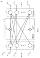
[0032]図1は、本開示のいくつかの態様による、複数のレベルのニューロンをもつ例示的な人工ニューラルシステム100を示す。ニューラルシステム100は、シナプス結合のネットワーク104(すなわち、フィードフォワード結合)を介してニューロンの別のレベル106に結合されたニューロンのあるレベル102を有し得る。簡単のために、図1には2つのレベルのニューロンのみが示されているが、ニューラルシステムには、より少ないまたはより多くのレベルのニューロンが存在し得る。ニューロンのいくつかは、ラテラル結合を介して同じ層の他のニューロンに結合し得ることに留意されたい。さらに、ニューロンのいくつかは、フィードバック結合を介して前の層のニューロンに戻る形で結合し得る。
(Exemplary neural system, training and operation)
[0032] FIG. 1 illustrates an exemplary artificial
[0033]図1に示すように、レベル102における各ニューロンは、前のレベル(図1に図示せず)のニューロンによって生成され得る入力信号108を受信し得る。信号108は、レベル102のニューロンの入力電流を表し得る。この電流は、膜電位を充電するためにニューロン膜上に蓄積され得る。膜電位がそれのしきい値に達すると、ニューロンは、発火し、ニューロンの次のレベル(たとえば、レベル106)に転送されるべき出力スパイクを生成し得る。いくつかのモデリング手法では、ニューロンは、信号をニューロンの次のレベルに継続的に転送し得る。この信号は、典型的には膜電位の関数である。そのような挙動は、以下で説明するものなどのアナログおよびデジタル実装形態を含むハードウェアおよび/またはソフトウェアでエミュレートまたはシミュレートされ得る。
[0033] As shown in FIG. 1, each neuron at
[0034]生物学的ニューロンでは、ニューロンが発火するときに生成される出力スパイクは、活動電位と呼ばれる。電気信号は、約100mVの振幅と約1msの持続時間とを有する比較的急速で、一時的な神経インパルスである。一連の結合されたニューロンを有するニューラルシステムの特定の実施形態(たとえば、図1におけるあるレベルのニューロンから別のレベルのニューロンへのスパイクの転送)では、あらゆる活動電位が基本的に同じ振幅と持続時間とを有するので、信号における情報は、振幅によってではなく、スパイクの周波数および数、またはスパイクの時間によってのみ表され得る。活動電位によって搬送される情報は、スパイク、スパイクしたニューロン、および他の1つまたは複数のスパイクに対するスパイクの時間によって決定され得る。以下で説明するように、スパイクの重要性は、ニューロン間の接続に適用される重みによって決定され得る。 [0034] In biological neurons, the output spike that is generated when a neuron fires is called the action potential. The electrical signal is a relatively rapid, transient nerve impulse having an amplitude of about 100 mV and a duration of about 1 ms. In certain embodiments of a neural system with a series of coupled neurons (eg, the transfer of spikes from one level of neurons to another in FIG. 1), all action potentials are essentially the same amplitude and duration. Information in the signal can be represented only by the frequency and number of spikes, or by the time of the spikes, not by the amplitude. The information carried by the action potential can be determined by the time of the spike relative to the spike, the spiked neuron, and one or more other spikes. As explained below, the importance of spikes can be determined by the weights applied to connections between neurons.
[0035]図1に示されるように、ニューロンのあるレベルから別のレベルへのスパイクの移動は、シナプス結合(または、単純に「シナプス」)104のネットワークを介して達成され得る。シナプス104に関して、レベル102のニューロンはシナプス前ニューロンと考えられ得、レベル106のニューロンはシナプス後ニューロンと考えられ得る。シナプス104は、レベル102のニューロンから出力信号(すなわち、スパイク)を受信して、調整可能なシナプスの重み

[0036]生物学的シナプスは、シナプス後ニューロンにおける興奮性活動または抑制性(過分極化)活動のいずれかを調停することができ、ニューロン信号を増幅する役目を果たすことができる。興奮性信号は、膜電位を脱分極する(すなわち、静止電位に対して膜電位を増加させる)。しきい値を超えて膜電位を脱分極するために十分な興奮性信号が一定の時間期間内に受信された場合、シナプス後ニューロンに活動電位が生じる。対照的に、抑制性信号は一般に、膜電位を過分極する(すなわち、低下させる)。抑制性信号は、十分に強い場合、興奮性信号のすべてを相殺し、膜電位がしきい値に達するのを防止することができる。シナプス興奮を相殺することに加えて、シナプス抑制は、自然に活発なニューロンに対して強力な制御を行うことができる。自然に活発なニューロンは、たとえば、それのダイナミクスまたはフィードバックに起因するさらなる入力なしにスパイクするニューロンを指す。これらのニューロンにおける活動電位の自然な生成を抑圧することによって、シナプス抑制は、一般にスカルプチャリングと呼ばれる、ニューロンの発火のパターンを形成することができる。様々なシナプス104は、望まれる挙動に応じて、興奮性シナプスまたは抑制性シナプスの任意の組合せとして働き得る。
[0036] Biological synapses can mediate either excitatory or inhibitory (hyperpolarized) activity in post-synaptic neurons and can serve to amplify neuronal signals. The excitatory signal depolarizes the membrane potential (ie increases the membrane potential relative to the resting potential). If a sufficient excitatory signal is received within a certain time period to depolarize the membrane potential beyond the threshold, an action potential is generated in the post-synaptic neuron. In contrast, inhibitory signals generally hyperpolarize (ie, reduce) membrane potential. If the inhibitory signal is strong enough, it can cancel all of the excitatory signal and prevent the membrane potential from reaching the threshold. In addition to offsetting synaptic excitement, synaptic inhibition can provide powerful control over naturally active neurons. A naturally active neuron refers to a neuron that spikes without further input due to, for example, its dynamics or feedback. By suppressing the natural generation of action potentials in these neurons, synaptic inhibition can form a pattern of neuronal firing, commonly referred to as sculpting. The
[0037]ニューラルシステム100は、汎用プロセッサ、デジタル信号プロセッサ(DSP)、特定用途向け集積回路(ASIC)、フィールドプログラマブルゲートアレイ(FPGA)もしくは他のプログラマブル論理デバイス(PLD)、個別ゲートもしくはトランジスタ論理、個別ハードウェア構成要素、プロセッサによって実行されるソフトウェアモジュール、またはそれらの任意の組合せによってエミュレートされ得る。ニューラルシステム100は、たとえば画像およびパターン認識、機械学習、モータ制御、および似ているなど、かなりの適用範囲において利用され得る。ニューラルシステム100における各ニューロンは、ニューロン回路として実装され得る。出力スパイクを開始するしきい値まで充電されるニューロン膜は、たとえば、そこを通って流れる電流を積分するキャパシタとして実装され得る。
[0037] The
[0038]一態様では、キャパシタは、ニューロン回路の電流積分デバイスとして除去され得、その代わりにより小さいメモリスタ(memristor)要素が使用され得る。この手法は、ニューロン回路において、ならびにかさばるキャパシタが電流積分器として利用される様々な他の適用例において適用され得る。さらに、シナプス104の各々は、メモリスタ要素に基づいて実装され得、シナプス重みの変化は、メモリスタ抵抗の変化に関係し得る。ナノメートルの特徴サイズのメモリスタを用いると、ニューロン回路およびシナプスの面積が大幅に低減され得、それによって、大規模なニューラルシステムハードウェア実装形態の実装がより実用的になり得る。
[0038] In one aspect, the capacitor may be removed as a current integrating device of a neuron circuit, and a smaller memristor element may be used instead. This approach can be applied in neuron circuits as well as in various other applications where bulky capacitors are utilized as current integrators. Further, each of the
[0039]ニューラルシステム100をエミュレートするニューラルプロセッサの機能は、ニューロン間の結合の強さを制御し得る、シナプス結合の重みに依存し得る。シナプス重みは、パワーダウン後にプロセッサの機能を維持するために、不揮発性メモリに記憶され得る。一態様では、シナプス重みメモリは、主たるニューラルプロセッサチップとは別個の外部チップ上に実装され得る。シナプス重みメモリは、交換可能メモリカードとしてニューラルプロセッサチップとは別個にパッケージ化され得る。これは、ニューラルプロセッサに多様な機能を提供することができ、特定の機能は、ニューラルプロセッサに現在取り付けられているメモリカードに記憶されたシナプス重みに基づき得る。
[0039] The ability of the neural processor to emulate the
[0040]図2は、本開示のいくつかの態様による、計算ネットワーク(たとえば、ニューラルシステムまたはニューラルネットワーク)の処理ユニット(たとえば、ニューロンまたはニューロン回路)202の一例200を示す。たとえば、ニューロン202は、図1のレベル102のニューロンおよび106のニューロンのうちのいずれかに対応し得る。ニューロン202は、ニューラルシステムの外部にある信号、または同じニューラルシステムの他のニューロンによって生成された信号、またはその両方であり得る、複数の入力信号2041〜204N(X1〜XN)を受信し得る。入力信号は、実数値または複素数値の、電流、コンダクタンス、または電圧であり得る。入力信号は、固定小数点表現または浮動小数点表現をもつ数値を備え得る。これらの入力信号は、調整可能なシナプス重み2061〜206N(w1〜wN)に従って信号をスケーリングするシナプス結合を通してニューロン202に伝えられ得、Nはニューロン202の入力接続の総数であり得る。
[0040] FIG. 2 illustrates an example 200 of a processing unit (eg, a neuron or neuron circuit) 202 of a computational network (eg, a neural system or neural network) according to some aspects of the present disclosure. For example,
[0041]ニューロン202は、スケーリングされた入力信号を合成し、合成された、スケーリングされた入力を使用して、出力信号208(すなわち、信号y)を生成し得る。出力信号208は、実数値または複素数値の、電流、コンダクタンス、または電圧であり得る。出力信号は、固定小数点表現または浮動小数点表現をもつ数値であり得る。出力信号208は、次いで、同じニューラルシステムの他のニューロンへの入力信号として、または同じニューロン202への入力信号として、またはニューラルシステムの出力として伝達され得る。
[0041]
[0042]処理ユニット(ニューロン)202は電気回路によってエミュレートされ得、それの入力接続および出力接続は、シナプス回路をもつ電気接続によってエミュレートされ得る。処理ユニット202ならびにそれの入力接続および出力接続はまた、ソフトウェアコードによってエミュレートされ得る。処理ユニット202はまた、電気回路によってエミュレートされ得るが、それの入力接続および出力接続はソフトウェアコードによってエミュレートされ得る。一態様では、計算ネットワーク中の処理ユニット202はアナログ電気回路であり得る。別の態様では、処理ユニット202はデジタル電気回路であり得る。さらに別の態様では、処理ユニット202は、アナログ構成要素とデジタル構成要素の両方をもつ混合信号電気回路であり得る。計算ネットワークは、上述の形態のいずれかにおける処理ユニットを含み得る。そのような処理ユニットを使用した計算ネットワーク(ニューラルシステムまたはニューラルネットワーク)は、たとえば画像およびパターン認識、機械学習、モータ制御など、かなりの適用範囲において利用され得る。
[0042] The processing unit (neuron) 202 may be emulated by an electrical circuit, and its input and output connections may be emulated by an electrical connection with a synaptic circuit. The
[0043]ニューラルネットワークをトレーニングする過程で、シナプス重み(たとえば、図1の重み
(シナプスタイプ)
[0044]ニューラルネットワークのハードウェアおよびソフトウェアモデルでは、シナプス関係機能の処理がシナプスタイプに基づき得る。シナプスタイプは、非塑性シナプス(non-plastic synapse)(重みおよび遅延の変化がない)、可塑性シナプス(重みが変化し得る)、構造遅延可塑性シナプス(重みおよび遅延が変化し得る)、完全可塑性シナプス(重み、遅延および結合性が変化し得る)、およびそれの変形(たとえば、遅延は変化し得るが、重みまたは結合性の変化はない)を備え得る。これの利点は、処理が再分割され得ることである。たとえば、非塑性シナプスは、可塑性機能を実行する(またはそのような機能が完了するのを待つ)必要がない場合がある。同様に、遅延および重み可塑性は、一緒にまたは別々に、順にまたは並列に動作し得る動作に再分割され得る。異なるタイプのシナプスは、適用される異なる可塑性タイプの各々の異なるルックアップテーブルまたは式およびパラメータを有し得る。したがって、本方法は、シナプスのタイプについての関連する表、式、またはパラメータにアクセスする。
(Synaptic type)
[0044] In neural network hardware and software models, the processing of synapse-related functions may be based on synapse types. Synapse types are: non-plastic synapse (no change in weight and delay), plastic synapse (weight can change), structural delay plastic synapse (weight and delay can change), fully plastic synapse (The weight, delay and connectivity may change), and variations thereof (eg, the delay may change, but the weight or connectivity does not change). The advantage of this is that the process can be subdivided. For example, a non-plastic synapse may not need to perform a plastic function (or wait for such function to complete). Similarly, delay and weight plasticity can be subdivided into operations that can operate together or separately, in sequence or in parallel. Different types of synapses may have different look-up tables or formulas and parameters for each of the different plasticity types that are applied. Thus, the method accesses an associated table, formula or parameter for the type of synapse.
[0045]スパイクタイミング依存構造可塑性がシナプス可塑性とは無関係に実行され得るという事実のさらなる含意がある。構造可塑性(すなわち、遅延量の変化)は前後スパイク時間差(pre-post spike time difference)の直接関数であり得るので、構造可塑性が重みの大きさに変化がない場合(たとえば、重みが最小値または最大値に達したか、あるいはそれが何らかの他の理由により変更されない場合)でも実行され得る。代替的に、構造可塑性は、重み変化量に応じて、または重みもしくは重み変化の限界に関係する条件に基づいて設定され得る。たとえば、重み変化が生じたとき、または重みが最大値に達するのではなく、重みがゼロに達した場合のみ、シナプス遅延が変化し得る。しかしながら、これらのプロセスが並列化され、メモリアクセスの数および重複を低減し得るように、独立した機能を有することが有利であり得る。 [0045] There is a further implication of the fact that spike timing dependent structural plasticity can be performed independently of synaptic plasticity. Structural plasticity (ie, the change in delay) can be a direct function of the pre-post spike time difference, so if the structural plasticity does not change in the weight magnitude (for example, the weight is the minimum or Even if the maximum value has been reached or it has not been changed for some other reason). Alternatively, the structural plasticity can be set according to the amount of weight change or based on conditions related to the weight or limit of weight change. For example, the synaptic delay can change only when a weight change occurs or when the weight reaches zero instead of reaching the maximum value. However, it may be advantageous to have independent functions so that these processes can be parallelized to reduce the number and overlap of memory accesses.
(シナプス可塑性の決定)
[0046]神経可塑性(または単に「可塑性」)は、脳内のニューロンおよびニューラルネットワークがそれらのシナプス結合と挙動とを新しい情報、感覚上の刺激、発展、損傷または機能不全に応答して変える能力である。可塑性は、生物学における学習および記憶にとって、また計算論的神経科学およびニューラルネットワークにとって重要である。(たとえば、Hebb則理論による)シナプス可塑性、スパイクタイミング依存可塑性(STDP)、非シナプス可塑性、活性依存可塑性、構造可塑性および恒常的可塑性など、様々な形の可塑性が研究されている。
(Determining synaptic plasticity)
[0046] Neuroplasticity (or simply “plasticity”) is the ability of neurons and neural networks in the brain to change their synaptic connections and behavior in response to new information, sensory stimuli, development, injury or dysfunction It is. Plasticity is important for learning and memory in biology and for computational neuroscience and neural networks. Various forms of plasticity have been studied, including synaptic plasticity (eg, according to Hebb's law theory), spike timing dependent plasticity (STDP), non-synaptic plasticity, activity dependent plasticity, structural plasticity and permanent plasticity.
[0047]STDPは、ニューロン間のシナプス結合の強さを調整する学習プロセスである。結合強度は、特定のニューロンの出力スパイクおよび受信入力スパイク(すなわち、活動電位)の相対的タイミングに基づいて調整される。STDPプロセスの下で、あるニューロンに対する入力スパイクが、平均して、そのニューロンの出力スパイクの直前に生じる傾向がある場合、長期増強(LTP)が生じ得る。その場合、その特定の入力はいくらか強くなる。一方、入力スパイクが、平均して、出力スパイクの直後に生じる傾向がある場合、長期抑圧(LTD)が生じ得る。その場合、その特定の入力はいくらか弱くなるので、「スパイクタイミング依存可塑性」と呼ばれる。したがって、シナプス後ニューロンの興奮の原因であり得る入力は、将来的に寄与する可能性がさらに高くなる一方、シナプス後スパイクの原因ではない入力は、将来的に寄与する可能性が低くなる。結合の初期セットのサブセットが残る一方で、その他の部分の影響がわずかなレベルまで低減されるまで、このプロセスは続く。 [0047] STDP is a learning process that adjusts the strength of synaptic connections between neurons. The bond strength is adjusted based on the relative timing of the output spike and receive input spike (ie, action potential) of a particular neuron. Under the STDP process, long-term potentiation (LTP) can occur if, on average, an input spike for a neuron tends to occur on average just before that neuron's output spike. In that case, that particular input will be somewhat stronger. On the other hand, long term suppression (LTD) can occur if the input spikes tend to occur on average immediately after the output spike. In that case, that particular input is somewhat weaker and is called "spike timing dependent plasticity". Thus, inputs that may be responsible for the excitement of post-synaptic neurons are more likely to contribute in the future, while inputs that are not the cause of post-synaptic spikes are less likely to contribute in the future. This process continues until the subset of the initial set of joins remains, while the influence of the other parts is reduced to a slight level.
[0048]ニューロンは一般に出力スパイクを、当該ニューロンの入力の多くが短い期間内に生じる、すなわち、出力をもたらすのに十分な累積があるときに生成するので、通常残っている入力のサブセットは、時間的に相関する傾向のあった入力を含む。さらに、出力スパイクの前に生じる入力は強化されるので、最も早い十分に累積的な相関指示を提供する入力が結局、ニューロンへの最終入力となる。 [0048] Since neurons generally generate output spikes when many of the neuron's inputs occur within a short period of time, ie, there is sufficient accumulation to produce an output, the subset of inputs that typically remain is Includes inputs that tend to be correlated in time. Furthermore, since the input that occurs before the output spike is enhanced, the input that provides the earliest fully cumulative correlation indication is ultimately the final input to the neuron.
[0049]STDP学習ルールは、シナプス前ニューロンのスパイク時間tpreとシナプス後ニューロンのスパイク時間tpostとの間の時間差(すなわち、t=tpost−tpre)に応じて、シナプス前ニューロンをシナプス後ニューロンに結合するシナプスのシナプス重みを効果的に適合させ得る。STDPの通常の公式化は、時間差が正である(シナプス前ニューロンがシナプス後ニューロンの前に発火する)場合にシナプス重みを増加させ(すなわち、シナプスを増強し)、時間差が負である(シナプス後ニューロンがシナプス前ニューロンの前に発火する)場合にシナプス重みを減少させる(すなわち、シナプスを抑制する)ことである。 [0049] The STDP learning rule synchronizes presynaptic neurons according to the time difference between the presynaptic neuron spike time t pre and the post synaptic neuron spike time t post (ie, t = t post −t pre ). Synaptic weights of synapses that connect to post-neurons can be effectively adapted. The usual formulation of STDP is to increase the synaptic weight when the time difference is positive (the presynaptic neuron fires before the post-synaptic neuron) (ie, enhances the synapse) and the time difference is negative (post-synaptic). Reducing synaptic weights (ie, suppressing synapses) when neurons fire before presynaptic neurons).
[0050]STDPプロセスでは、経時的なシナプス重みの変化は通常、以下の式によって与えられるように、指数関数的減衰を使用して達成され得る。
[0051]図3は、STDPによる、シナプス前スパイクおよびシナプス後スパイクの相対的タイミングに応じたシナプス重み変化の例示的なグラフ図300を示す。シナプス前ニューロンがシナプス後ニューロンの前に発火する場合、グラフ300の部分302に示すように、対応するシナプス重みは増加し得る。この重み増加は、シナプスのLTPと呼ばれ得る。グラフ部分302から、シナプス前スパイク時間とシナプス後スパイク時間との間の時間差に応じて、LTPの量がほぼ指数関数的に減少し得ることが観測され得る。グラフ300の部分304に示すように、発火の逆の順序は、シナプス重みを減少させ、シナプスのLTDをもたらし得る。
[0051] FIG. 3 shows an exemplary graphical diagram 300 of synaptic weight changes as a function of the relative timing of pre- and post-synaptic spikes according to STDP. If a pre-synaptic neuron fires before a post-synaptic neuron, the corresponding synaptic weight may increase as shown in
[0052]図3のグラフ300に示すように、STDPグラフのLTP(原因)部分302に負のオフセットμが適用され得る。x軸の交差306のポイント(y=0)は、層i−1からの原因入力の相関を考慮して、最大タイムラグと一致するように構成され得る。フレームベースの入力(すなわち、スパイクまたはパルスを備える特定の持続時間のフレームの形態である入力)の場合、オフセット値μは、フレーム境界を反映するように計算され得る。直接的にシナプス後電位によってモデル化されるように、またはニューラル状態に対する影響の点で、フレームにおける第1の入力スパイク(パルス)が経時的に減衰することが考慮され得る。フレームにおける第2の入力スパイク(パルス)が特定の時間フレームの相関したまたは関連したものと考えられる場合、フレームの前および後の関連する時間は、その時間フレーム境界で分離され、関連する時間の値が異なり得る(たとえば、1つのフレームよりも大きい場合は負、1つのフレームよりも小さい場合は正)ように、STDP曲線の1つまたは複数の部分をオフセットすることによって、可塑性の点で別様に扱われ得る。たとえば、曲線が、フレーム時間よりも大きい前後の時間で実際にゼロよりも下になり、結果的にLTPの代わりにLTDの一部であるようにLTPをオフセットするために負のオフセットμが設定され得る。
[0052] As shown in
(ニューロンモデルおよび演算)
[0053]有用なスパイキングニューロンモデルを設計するための一般的原理がいくつかある。良いニューロンモデルは、2つの計算レジーム、すなわち、一致検出および関数計算の点で豊かな潜在的挙動を有し得る。その上、良いニューロンモデルは、テンポラルコーディングを可能にするための2つの要素を有する必要がある:入力の到着時間は出力時間に影響を与え、一致検出は狭い時間ウィンドウを有し得る。最終的に、計算上魅力的であるために、良いニューロンモデルは、連続時間に閉形式解と、ニアアトラクター(near attractor)と鞍点とを含む安定した挙動とを有し得る。言い換えれば、有用なニューロンモデルは、実用的なニューロンモデルであり、豊かで、現実的で、生物学的に一貫した挙動をモデル化するために使用され得、神経回路のエンジニアリングとリバースエンジニアリングの両方を行うために使用され得るニューロンモデルである。
(Neuron model and calculation)
[0053] There are several general principles for designing useful spiking neuron models. A good neuron model may have rich potential behavior in terms of two computational regimes: coincidence detection and functional computation. Moreover, a good neuron model needs to have two elements to enable temporal coding: input arrival time affects output time, and coincidence detection can have a narrow time window. Finally, to be computationally attractive, a good neuron model can have a closed-form solution in continuous time, and a stable behavior that includes near attractors and saddle points. In other words, a useful neuron model is a practical neuron model that can be used to model rich, realistic and biologically consistent behavior, both in neural circuit engineering and reverse engineering A neuron model that can be used to perform
[0054]ニューロンモデルは事象、たとえば入力の到着、出力スパイク、または内部的であるか外部的であるかを問わず他の事象に依存し得る。豊かな挙動レパートリーを実現するために、複雑な挙動を示すことができる状態機械が望まれ得る。入力寄与(ある場合)とは別個の事象の発生自体が状態機械に影響を与え、事象の後のダイナミクスを制限し得る場合、システムの将来の状態は、単なる状態および入力の関数ではなく、むしろ状態、事象および入力の関数である。 [0054] The neuron model may depend on events, such as input arrivals, output spikes, or other events, whether internal or external. In order to achieve a rich behavioral repertoire, a state machine that can exhibit complex behavior may be desired. If the occurrence of an event separate from the input contribution (if any) affects the state machine itself and can limit the dynamics after the event, the future state of the system is not just a function of state and input, but rather It is a function of state, event and input.
[0055]一態様では、ニューロンnは、下記のダイナミクスによって決定される膜電圧vn(t)によるスパイキングリーキー積分発火ニューロンとしてモデル化され得る。
[0056]シナプス後ニューロンへの十分な入力が達成された時間からシナプス後ニューロンが実際に発火する時間までの遅延があることに留意されたい。イジケヴィッチの単純モデルなど、動的スパイキングニューロンモデルでは、脱分極しきい値vtとピークスパイク電圧vpeakとの間に差がある場合、時間遅延が生じ得る。たとえば、単純モデルでは、電圧および復元のための1対の微分方程式、すなわち、
(Hunzinger Coldモデル)
[0057]Hunzinger Coldニューロンモデルは、豊かな様々な神経挙動を再生し得る最小二重レジームスパイキング線形動的モデルである。モデルの1次元または2次元の線形ダイナミクスは2つのレジームを有することができ、時定数(および結合)はレジームに依存し得る。しきい値下レジームでは、時定数は、慣例により負であり、一般に生物学的に一貫した線形方式で静止状態に細胞を戻す役目を果たすリーキーチャネルダイナミクスを表す。しきい値上レジームにおける時定数は、慣例により正であり、一般にスパイク生成のレイテンシを生じさせる一方でスパイク状態に細胞を駆り立てる反リーキーチャネルダイナミクスを反映する。
(Hunzinger Cold model)
[0057] The Hunsinger Cold neuron model is a minimal double-regime spiking linear dynamic model that can reproduce a rich variety of neural behaviors. The one-dimensional or two-dimensional linear dynamics of the model can have two regimes, and the time constant (and combination) can depend on the regime. In the subthreshold regime, the time constant is negative by convention and generally represents leaky channel dynamics that serve to return cells to a quiescent state in a biologically consistent linear fashion. The time constant in the over-threshold regime is positive by convention and generally reflects anti-leaky channel dynamics that cause spike generation latencies while driving the cells to the spike state.
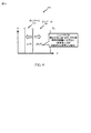
[0058]図4に示すように、モデルのダイナミクスは2つの(またはそれよりも多くの)レジームに分割され得る。これらのレジームは、負のレジーム(negative regime)402(leaky−integrate−and−fire(LIF)ニューロンモデルと混同されないように、交換可能にLIFレジームとも呼ばれる)、および正のレジーム(positive regime)404(anti−leaky−integrate−and−fire(ALIF)ニューロンモデルと混同されないように、交換可能にALIFレジームとも呼ばれる)と呼ばれ得る。負レジーム402では、状態は将来の事象の時点における静止(v-)の傾向がある。この負レジームでは、モデルは一般に、時間的入力検出特性と他のしきい値下挙動とを示す。正レジーム404では、状態はスパイキング事象(vs)の傾向がある。この正レジームでは、モデルは、後続の入力事象に応じてスパイクにレイテンシを生じさせるなどの計算特性を示す。事象の点からのダイナミクスの公式化およびこれら2つのレジームへのダイナミクスの分離は、モデルの基本的特性である。
[0058] As shown in FIG. 4, the dynamics of the model may be divided into two (or more) regimes. These regimes are negative regime 402 (also referred to interchangeably as LIF regime, so as not to be confused with the leaky-integrate-and-fire (LIF) neuron model), and
[0059]線形二重レジーム2次元ダイナミクス(状態vおよびuの場合)は、慣例により次のように定義され得る。
[0060]シンボルρは、ダイナミクスレジームを示すためにここで使用され、特定のレジームの関係を論述または表現するときに、それぞれ負レジームおよび正レジームについて符号「−」または「+」にシンボルρを置き換える慣例がある。 [0060] The symbol ρ is used here to indicate a dynamics regime, and when discussing or expressing the relationship of a particular regime, the symbol ρ is labeled with a symbol “−” or “+” for a negative regime and a positive regime, respectively. There are conventions to replace.
[0061]モデル状態は、膜電位(電圧)vおよび復元電流uによって定義される。基本形態では、レジームは基本的にモデル状態によって決定される。正確で一般的な定義の微妙だが重要な側面があるが、差し当たり、モデルが、電圧vがしきい値(v+)を上回る場合に正レジーム404にあり、そうでない場合に負レジーム402にあると考える。
[0061] The model state is defined by the membrane potential (voltage) v and the restoring current u. In the basic form, the regime is basically determined by the model state. There is a subtle but important aspect of the exact general definition, but for the time being the model is in the
[0062]レジーム依存時定数は、負レジーム時定数であるτ-と正レジーム時定数であるτ+とを含む。復元電流時定数τuは通常、レジームから独立している。便宜上、τuと同様に、指数およびτ+が一般に正となる正レジームに対して、電圧発展(voltage evolution)と同じ表現が使用され得るように、減衰を反映するために負の量として負レジーム時定数τ-が一般に指定される。 [0062] The regime dependent time constant includes a negative regime time constant τ − and a positive regime time constant τ + . The restoration current time constant τ u is usually independent of the regime. For convenience, as with τ u , for positive regimes where the exponent and τ + are generally positive, a negative amount is used to reflect the attenuation so that the same representation as voltage evolution can be used. A regime time constant τ − is generally specified.
[0063]2つの状態要素のダイナミクスは、事象において、ヌルクラインから状態をオフセットする変換によって結合され得、ここで変換変数は、
![]()
![]()
[0064]vおよびuのためのヌルクラインは、それぞれ変換変数qρおよびrの負によって与えられる。パラメータδは,uヌルクラインの傾きを制御するスケール係数である。パラメータεは通常、−v-に等しく設定される。パラメータβは、両方のレジームにおいてvヌルクラインの傾きを制御する抵抗値である。τρ時定数パラメータは、指数関数的減衰だけでなく、各レジームにおいて別個にヌルクラインの傾きを制御する。 [0064] The null Klein for v and u are given by the negative of the transformation variables q ρ and r, respectively. The parameter δ is a scale factor for controlling the slope of the u null line. The parameter ε is usually set equal to −v − . The parameter β is a resistance value that controls the slope of the v null null in both regimes. The τ ρ time constant parameter controls not only the exponential decay but also the null Klein slope separately in each regime.
[0065]モデルは、電圧vが値vsに達したときにスパイクするように定義され得る。続いて、状態は(スパイク事象と同じ1つのものであり得る)リセット事象でリセットされ得る。
![]()
![]()
[0066]瞬時結合の原理によって、状態について(また、単一の指数項による)だけではなく、特定の状態に到達するための時間についても、閉形式解が可能である。閉形式状態解は、次のとおりである。
[0067]したがって、モデル状態は、入力(シナプス前スパイク)または出力(シナプス後スパイク)に伴うなどの事象に伴ってのみ更新され得る。また、演算が(入力または出力があるかどうかを問わず)任意の特定の時間に実行され得る。 [0067] Thus, the model state can only be updated with events, such as with input (pre-synaptic spike) or output (post-synaptic spike). Also, operations can be performed at any particular time (whether there are inputs or outputs).
[0068]その上、瞬時結合原理によって、反復的技法または数値解法(たとえば、オイラー数値解法)なしに、特定の状態に到達する時間が事前に決定され得るように、シナプス後スパイクの時間が予想され得る。前の電圧状態v0を踏まえ、電圧状態vfに到達するまでの時間遅延は、次の式によって与えられる。
[0069]スパイクが、電圧状態vがvsに到達する時間に生じると定義される場合、電圧が所与の状態vにある時間から測定されたスパイクが生じるまでの時間量、または相対的遅延に関する閉形式解は、次のとおりである。
![]()
![]()
[0070]モデルダイナミクスの上記の定義は、モデルが正レジームにあるか、それとも負レジームにあるかに依存する。上述のように、結合およびレジームρは、事象に伴って計算され得る。状態の伝搬のために、レジームおよび結合(変換)変数は、最後の(前の)事象の時間における状態に基づいて定義され得る。続いてスパイク出力時間を予想するために、レジームおよび結合変数は、次の(最新の)事象の時間における状態に基づいて定義され得る。 [0070] The above definition of model dynamics depends on whether the model is in the positive or negative regime. As described above, the binding and regime ρ can be calculated with the event. For state propagation, regimes and binding (transformation) variables can be defined based on the state at the time of the last (previous) event. In order to subsequently predict the spike output time, the regime and binding variables can be defined based on the state at the time of the next (latest) event.
[0071]Coldモデルの、適時にシミュレーション、エミュレーションまたはモデルを実行するいくつかの可能な実装形態がある。これは、たとえば、事象更新モード、ステップ事象更新モード、およびステップ更新モードを含む。事象更新は、(特定の瞬間における)事象または「事象更新」に基づいて状態が更新される更新である。ステップ更新は、間隔(たとえば、1ms)をおいてモデルが更新される更新である。これは必ずしも、反復的技法または数値解法を必要とするとは限らない。また、事象がステップもしくはステップ間で生じる場合または「ステップ事象」更新によってモデルを更新するのみによって、ステップベースのシミュレータにおいて限られた時間分解能で事象ベースの実装形態が可能である。 [0071] There are several possible implementations of the Cold model to perform simulation, emulation or model in a timely manner. This includes, for example, an event update mode, a step event update mode, and a step update mode. An event update is an update whose state is updated based on an event (at a particular moment) or “event update”. The step update is an update in which the model is updated at intervals (for example, 1 ms). This does not necessarily require iterative techniques or numerical solutions. Also, an event-based implementation is possible with limited time resolution in a step-based simulator if events occur between steps or between steps or only by updating the model with “step event” updates.
(ニューラルプロセッサにわたる値同期)
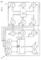
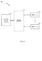
[0072]本開示の態様は、スパイクインターフェースを介してニューラルネットワーク内で値を同期することを対象とする。図5は、ニューラルネットワーク内のニューラルプロセッサ間で値を同期するための例示的なシステムアーキテクチャを示す高レベルブロック図である。システムアーキテクチャ500は、ニューラルシステムをエミュレートするために単独で、または組み合わせて利用され得るニューラルプロセッサ502と522を備える。さらに、ニューラルプロセッサ502と522は、同じ処理チップ内に含まれてもよく、別個の処理チップに提供されてもよい。図示および説明を簡単にするために、システムアーキテクチャ500は、2つのニューラルプロセッサ(502および522)を含むものとして示されている。しかしながら、これは単なる例示であり、ニューラルネットワーク内の処理のために、追加のニューラルプロセッサまたは処理ブロックがシステムアーキテクチャに含まれ得る。
(Value synchronization across neural processors)
[0072] Aspects of the present disclosure are directed to synchronizing values within a neural network via a spike interface. FIG. 5 is a high-level block diagram illustrating an exemplary system architecture for synchronizing values between neural processors in a neural network. System architecture 500 includes
ニューラルプロセッサ502は、値生成器(VG)504を備え得る。値生成器504は、ニューロンダイナミクスをモデル化するためにシステム内のニューロンと共有されることになる値を生成するように構成され得る。いくつかの態様では、値は、ニューロンパラメータ、シナプス重みまたは遅延値、あるいはニューラルシステムをエミュレートする際に使用するための他の値または属性であり得る。たとえば、値は、ニューラルネットワークにわたってニューロンに適用されることになる一般的なドーパミン値などのニューロモジュレータ値に対応し得る。別の例では、値は、発火した1つまたは複数のニューロン(たとえば、508)の識別情報に対応し得る。いくつかの態様では、値は、たとえば、特定のニューロンが発火する時間(τ)、あるいは値がニューロンによって適用または消費されることになるタイミングを示すために、タイミング情報をさらに含み得る。処理ブロック502、522ごとに1つの値生成器504、524があってもよく(図示されるように)、処理ブロック502、522ごとに複数の値生成器504、524があってもよい。たとえば、ニューロン508、528ごとに1つの値生成器504、524、あるいは、各処理ブロック502、522内のニューロンタイプまたはニューロンクラスタごとに1つの値生成器504、524さえもあり得る。
[0073]値生成器504は、たとえば、スパイクまたは他の属性(たとえば、シナプス重み、および/または遅延)などのニューラル特性に基づいて値を生成するために、値計算を実行するように構成され得る。いくつかの態様では、ニューロン508は、値計算に影響を与えるためにスパイクを値生成器504に送信し得る。さらに、ニューラルシステム内の遠隔プロセッサ(たとえば、522)のニューロンもまた、値計算に影響を与えるためにスパイクを値生成器504に送信し得る。さらに、図5は処理ブロック内に1つだけの値生成器を示すが、これは単なる例示であり、ニューラルプロセッサ502(ならびにニューラルプロセッサ522)は追加の値生成器と共に構成され得る。たとえば、ニューラルプロセッサ502、522は、ニューロンまたはニューロンタイプごとの値生成器と共に構成され得る。
[0073] The
[0074]ニューラルプロセッサ502はまた、値ニューロン(VN)506a、506b、506c(集合的に、値ニューロン506)を含み得る。値ニューロン506は、スパイクを生成するように構成され得る。スパイクは、バイナリ値に類似している。すなわち、スパイクはオンまたはオフのどちらかである。いくつかの態様では、値ニューロン506は、値生成器504によって生成された値に対応するスパイクを生成する。すなわち、値ニューロン506は、スパイクプロトコルに基づいて、値生成器504によって生成された値を符号化した出力スパイクを生成し得る。たとえば、値ニューロン506は、スパイク間隔(ISI)、バイナリ符号化、またはスパイクを生成するための他のプロトコルを使用してスパイクを符号化し得る。
[0074] The
[0075]いくつかの態様では、値ニューロン506の1つまたは複数は、ニューラルネットワーク内の他のニューロンと共有されることになる値を管理するために使用され得る。たとえば、値ニューロン506の1つまたは複数は、ニューロン508によって使用される値(たとえば、一般的なドーパミン値)を監視し得る。値に調整が行われると、値ニューロン506は、他のニューロン(たとえば、528)を更新して変化に対する値を利用するために使用され得る。 [0075] In some aspects, one or more of value neurons 506 may be used to manage values that will be shared with other neurons in the neural network. For example, one or more of the value neurons 506 may monitor the values used by the neurons 508 (eg, general dopamine values). As adjustments are made to values, value neurons 506 can be used to update other neurons (eg, 528) to take advantage of values for changes.
[0076]ニューラルプロセッサ502は、1つまたは複数のニューロン508a、508b(集合的に、ニューロン508と呼ばれ得る)をさらに備え得る。ニューロン508は、スパイク入力を受信して、ニューラルネットワーク内のニューロン挙動またはダイナミクスの態様をモデル化するために値を消費し得る。次に、ニューロン508は、ニューラルネットワーク内の他のニューロンに影響を与えるためにスパイクを出力し得る。いくつかの態様では、ニューロン508はまた、値生成器504を調整するために、スパイクを値ニューロン506に送信し得る。たとえば、ニューロン508は、値生成に影響を与える(たとえば、遅延させる)ために、スパイクを値ニューロン506に送信し得る。図5に示されるニューロン508はまた、個々のニューロンではなく、ニューロンタイプを表し得る。
[0076] The
[0077]ニューラルプロセッサ502は、インターフェース(図示せず)を介してニューラルネットワーク内の遠隔ニューラルプロセッサ(たとえば、522)に情報を送信して、そこから情報を受信するように構成され得る。いくつかの構成では、インターフェースは、図1に示されるようなシナプスのネットワークを備え得る。いくつかの態様では、インターフェースはスパイクだけを送受信するように構成され得る。そのような構成では、値生成器504によって生成されるスカラー値は、遠隔ニューラルプロセッサ(たとえば、522)に直接送信され得ない。しかしながら、スパイクはインターフェースを介して送信され得るので、値生成器504によって生成される値に関する情報は、値ニューロン506によって生成されるスパイクの形式で遠隔プロセッサに伝達され得る。すなわち、ニューラルプロセッサ502は、値ニューロン506を使用して値をスパイクに符号化して、スパイクを遠隔ニューラルプロセッサ522に送信することによって、値生成器504によって生成される値を遠隔ニューラルプロセッサ(たとえば、522)と共有し得る。
[0077]
[0078]ニューラルプロセッサ502から送信されたスパイクを受信するために、ニューラルプロセッサ522は、プロキシニューロン(P)526a、526b、および526c(集合的に、プロキシニューロン526と呼ばれる)を備え得る。プロキシニューロン526は、値ニューロン(たとえば、506)からスパイクを受信するように構成され得る。プロキシニューロン526は、スパイクおよび/または他の特性(たとえば、ニューロン状態)を値生成器524に提供し得る。そうする際に、プロキシニューロン526は、いくつかの態様では、受信されたスパイクに基づいて遠隔ニューラルプロセッサ522上で値を生成するために、値生成器524を駆動し得る。
[0078] To receive spikes transmitted from the
[0079]次に、値生成器524は、受信されたスパイクおよび/または他の特性に基づいて値を生成するために値計算を実行し得る。いくつかの態様では、値生成器524は、値が値生成器504によって生成された第1の値と同期されるように、値を生成するために値計算を実行するように構成され得る。さらに、いくつかの態様では、値生成器524は、値生成器504によって生成された値と同じ値を生成するように構成され得る。
[0079] The
[0080]ニューロン528a、528b、528c(集合的に、ニューロン528と呼ばれ得る)の1つまたは複数は、ニューラルネットワーク内のニューロン挙動またはダイナミクスの態様をさらにモデル化するために、値生成器524によって生成された値を消費し得る。
[0080] One or more of
[0081]いくつかの態様では、ニューラルプロセッサ522は、値生成器524によって生成された値のルーティングを決定するために、接続性ルックアップテーブルにアクセスし得る。接続性ルックアップテーブルは、生成された値のソース情報および宛先情報を提供し得る。すなわち、接続性ルックアップテーブルは、特定の値を消費することになるニューロンを識別し得る。
[0081] In some aspects, the
[0082]いくつかの態様では、接続性ルックアップテーブルは、値生成器(たとえば、504、524)を介して生成された値のルーティングを決定するために使用され得る。接続性ルックアップテーブルは、ソース情報および宛先情報を含み得、どのニューロン(たとえば、508、528)が生成された値を受信することになるかを決定するために使用され得る。たとえば、値生成器524によって生成された値が、発火したシナプス前ニューロンを識別する場合、接続性ルックアップテーブルは、発火したシナプス前ニューロンから貢献を受ける(receive contribution)ニューロン528を決定するために使用され得る。別の例では、値生成器524によって生成された値が、共有されたニューロモジュレータ値(たとえば、一般的なドーパミン値)に対応する場合、接続性テーブルは、生成された値を消費するニューロン528を示し得る。
[0082] In some aspects, a connectivity lookup table may be used to determine the routing of values generated via a value generator (eg, 504, 524). The connectivity lookup table may include source information and destination information and may be used to determine which neurons (eg, 508, 528) will receive the generated value. For example, if the value generated by the
[0083]さらに、場合によっては、ニューロン508と528は、値生成器(504)によって生成された値を調整するために、スパイクを値ニューロン(506)に送信し得る。他の場合では、ニューロン508と528は、値生成器524によって生成された値を調整するために、スパイクをプロキシニューロン526に送信し得る。
[0083] Further, in some cases, neurons 508 and 528 may send spikes to value neurons (506) to adjust the values generated by value generator (504). In other cases, neurons 508 and 528 may send spikes to proxy neuron 526 to adjust the value generated by
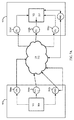
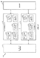
[0084]図6は、ニューラルネットワーク内のニューラルプロセッサ間で値を同期するための例示的なシステムアーキテクチャを示す高レベルブロック図である。図6に示すように、ニューラルプロセッサ502は、追加のプロキシニューロン616a、616b、および616c(集合的に、プロキシニューロン616と呼ばれる)で構成され得る。プロキシニューロン616は、第1のニューラルプロセッサ502の値ニューロン(506)と値生成器(504)との間で定義され得る。いくつかの態様では、プロキシニューロン616は、第1のニューラルプロセッサ502から第2のニューラルプロセッサ522にスパイクを送信する際に生成された遅延を複製するために利用され得る。
[0084] FIG. 6 is a high-level block diagram illustrating an exemplary system architecture for synchronizing values between neural processors in a neural network. As shown in FIG. 6, the
[0085]さらに、ニューラルプロセッサ502は、遅延生成器626と共に構成され得る。図6に示すように、遅延生成器626はニューラルプロセッサ502内で定義され得る。しかしながら、これは単なる例示であり、遅延生成器626はニューラルプロセッサ502の他の構成要素内に含まれてもよく、別個の構成要素として提供されてもよい。いくつかの態様では、遅延生成器626は、ニューラルプロセッサ502から第2のニューラルプロセッサ522にスパイクを送信する際に生成された遅延を複製するために使用され得る。遅延は、プロセッサ502、522間の遅延を近似してもよく、近似された遅延が実際の遅延よりも長くなるようにいくつかのパディングを含んでもよい。いくつかの構成では、ニューラルプロセッサ522はまた、ニューラルプロセッサ522からニューラルプロセッサ502にスパイクを送信する際に生成された遅延を複製する遅延生成器と共に構成され得る。
[0085] Further, the
[0086]さらに、いくつかの構成では、第1のニューラルプロセッサ502の値ニューロン506は、第2のニューラルプロセッサ522をリセットするために、スパイクの特定のシーケンスを送信し得る。
[0086] Further, in some configurations, the value neuron 506 of the first
[0087]遠隔ニューラルプロセッサ522上のニューロンは、第1のニューラルプロセッサ502から提供された値にアクセスし得る。したがって、ニューラルプロセッサ502内で生成された値は、遠隔ニューラルプロセッサ522内で生成された値と同期されたと見なされ得る。
[0087] Neurons on the remote
[0088]図7Aは、スパイクを符号化および復号化するための例示的なシステムを示す高レベルブロック図である。上述のように、値ニューロン506は、ニューラルネットワークにわたってニューロンと共有されることになる値V1を監視または管理し得る。いくつかの態様では、値V1は、特定の時間にスパイクしたニューロンの表示を提供し得る。値V1はまた、ニューロモジュレータ値(たとえば、一般的なドーパミン値)などの、ニューラルネットワークにわたってニューロンによって共有されることになる値であり得る。 [0088] FIG. 7A is a high-level block diagram illustrating an exemplary system for encoding and decoding spikes. As described above, the value neuron 506 may monitor or manage the value V1 that will be shared with the neuron across the neural network. In some aspects, the value V1 may provide an indication of neurons spiked at a particular time. The value V1 can also be a value that will be shared by neurons across a neural network, such as a neuromodulator value (eg, a general dopamine value).
[0089]図7Aの例では、値ニューロン506が値V1を管理する。値V1がニューラルネットワークにわたってニューロンと共有されることになる場合、値ニューロン506は、値V1を、ブロック間インターフェースを横切る送信のためのスパイクに変換するために使用され得る。いくつかの態様では、ブロック間インターフェース712は、スパイクだけがインターフェースを介して伝達され得るように構成され得、たとえばシナプスのネットワークであり得る。さらに、ブロック間インターフェース712は、ニューラルプロセッサ間のスパイクチャネルとして動作するように構成され得る。
[0089] In the example of FIG. 7A, value neuron 506 manages value V1. If value V1 will be shared with neurons across the neural network, value neuron 506 may be used to convert value V1 into a spike for transmission across the block-to-block interface. In some aspects, the
[0090]いくつかの態様では、値は1つまたは複数の構成要素部分に分割され得る。たとえば、値V1は、その最上位ビットと最下位ビットとに分割され得る。別の例では、値V1は、あらかじめ定められた数の部分(たとえば、ビットの1/2、ビットの1/3等)に分割され得る。 [0090] In some aspects, the value may be divided into one or more component parts. For example, the value V1 may be divided into its most significant bit and least significant bit. In another example, the value V1 may be divided into a predetermined number of parts (eg, 1/2 bit, 1/3 bit, etc.).
[0091]値ニューロン506は、スパイクプロトコルに基づいて値V1を符号化したスパイクを生成し得る。スパイクプロトコルは、たとえば、絶対レイテンシコーディング、相対レイテンシコーディング、レートコーディング、ISI(スパイク間隔)コーディング、バイナリコーディングなどの符号化方式を採用し得る。 [0091] The value neuron 506 may generate a spike that encodes the value V1 based on a spike protocol. The spike protocol may employ, for example, an encoding scheme such as absolute latency coding, relative latency coding, rate coding, ISI (spike interval) coding, and binary coding.
[0092]絶対レイテンシコーディングでは、値は、特定のニューロンまたはニューロンのセットのスパイク事象間の時間に基づいて符号化され得る。たとえば、8の値を符号化するために、ニューロンのスパイク事象間に8ミリ秒の遅延が含まれ得る。いくつかの態様では、値はまた、符号化された値を生成するためにスケーリングされ得る。さらに、いくつかの態様では、符号化された値は絶対レイテンシ値の関数であり得る。 [0092] In absolute latency coding, a value may be encoded based on the time between spike events of a particular neuron or set of neurons. For example, to encode a value of 8, an 8 millisecond delay may be included between neuronal spike events. In some aspects, the value can also be scaled to produce an encoded value. Further, in some aspects, the encoded value may be a function of the absolute latency value.
[0093]相対レイテンシコーディングでは、値は、複数のニューロンのスパイク間の間隔に従って符号化され得る。たとえば、ニューロンN1が時間t1でスパイクして、ニューロンN2が時間t2でスパイクする場合、値は時間差t2−t1として表され得る。 [0093] In relative latency coding, values may be encoded according to the spacing between spikes of multiple neurons. For example, if neuron N 1 spikes at time t 1 and neuron N 2 spikes at time t 2 , the value may be expressed as a time difference t 2 −t 1 .
[0094]レートコーディングでは、値は、特定の間隔内で発生するスパイクの数に従って表され得る。たとえば、スパイクは10ミリ秒間隔でサンプリングされ得、符号化された値は10ミリ秒の期間中に発生したスパイクの数に対応する。いくつかの態様では、値は1つのニューロンのスパイクレートに基づいて符号化されてもよく、複数のニューロンのスパイクレートに基づいて符号化されてもよい。 [0094] In rate coding, values may be represented according to the number of spikes that occur within a particular interval. For example, spikes can be sampled at 10 millisecond intervals, and the encoded value corresponds to the number of spikes that occurred during the 10 millisecond period. In some aspects, the value may be encoded based on the spike rate of one neuron, or may be encoded based on the spike rate of multiple neurons.
[0095]上述の符号化方式は単なる例示であり、いくつかの態様では、スパイクプロトコルはスパイク間隔(ISI)コーティング、バイナリコーディング、または値V1を符号化したスパイクを生成するための他の符号化方式を採用し得る。 [0095] The encoding scheme described above is merely exemplary, and in some aspects, the spike protocol may be spike interval (ISI) coating, binary coding, or other encoding to generate a spike encoded value V1. A scheme can be adopted.
[0096]スパイクした特定のニューロンまたは複数のニューロンを示す接続性情報はまた、値ニューロンを介して送信されたスパイクに含まれ得る。接続性情報は、符号化されて、スパイクとして遠隔ニューラルプロセッサ(たとえば、522)内のニューロンに送信された値をルーティングするために使用され得る。いくつかの態様では、接続性情報は、スパイクした1つまたは複数のニューロン(すなわち、ソースニューロン)を識別するインデックスを含み得る。接続性情報は、スパイクしたニューロンに基づいて貢献を受けることになる1つまたは複数のニューロンを識別する宛先情報をさらに含み得る。 [0096] Connectivity information indicating the particular neuron or neurons that were spiked may also be included in spikes transmitted via value neurons. The connectivity information can be encoded and used to route values sent as spikes to neurons in a remote neural processor (eg, 522). In some aspects, the connectivity information may include an index that identifies the spiked one or more neurons (ie, source neurons). The connectivity information may further include destination information that identifies one or more neurons that will receive a contribution based on the spiked neurons.
[0097]プロキシニューロン526は、処理ブロック502から送信されたスパイクを受信する。いくつかの態様では、スパイクは、スパイク送信問題(たとえば、スパイク損失)から回復するための冗長性を提供する追加の受信ニューロンによって受信され得る。たとえば、いくつかの態様では、値ニューロン506aを介して送信されたスパイク列は、複数のプロキシニューロン(たとえば、(526a、526b、および/または526c)を介して受信され得る。さらなる例では、スパイク列は、ニューラルプロセッサ522のプロキシニューロン526およびニューロン528を介して受信した。
[0097] The proxy neuron 526 receives the spike transmitted from the
[0098]次いで、プロキシニューロン526は、第1の値またはその構成要素に対応するスパイクを、スパイクを復号して第2の値V2を生成する値生成器524に提供する。いくつかの態様では、値生成器524は、値ニューロン506によって採用されたスパイクプロトコルに基づいて符号化されたスパイクを復号するように構成され得る。スパイクはタイミング情報が符号化され得るので、第2の値V2は、第2の値V2が第1の値V1と同期されるように生成され得る。いくつかの態様では、第2の値V2は、第1の値V1と同じであるか、等しい。
[0098] The proxy neuron 526 then provides a spike corresponding to the first value or component thereof to a
[0099]いくつかの態様では、接続性ルックアップテーブルは、生成された値のルーティングを決定するために使用され得る。接続性ルックアップテーブルは、ソース情報および宛先情報を含み得、ニューラルプロセッサ522のどのニューロンが、値生成器524によって生成された値を受信することになるかを決定するために使用され得る。たとえば、値生成器524によって生成された値が、発火したシナプス前ニューロンまたは複数のニューロンを識別するインデックスを含む場合、接続性ルックアップテーブルは、発火したシナプス前ニューロンから貢献を受けるニューロン528(図5および図6)を決定するために使用され得る。別の例では、値生成器524によって生成された値が共有されたニューロモジュレータ値(たとえば、一般的なドーパミン値)に対応する場合、接続性テーブルは、生成された値を消費することになるニューロン528を示し得る。
[0099] In some aspects, a connectivity lookup table may be used to determine the routing of generated values. The connectivity lookup table can include source information and destination information and can be used to determine which neurons of the
[00100]図7Bは、本開示の態様による、例示的な符号化技法を示す一対のグラフ750と760を示す。図7Bを参照すると、グラフ750は、スパイク間隔に基づく値の符号化の例を示す。すなわち、スパイク列は、ニューロンのスパイク事象間の時間ステップの数に従って値情報を表すように構成され得る。グラフ750に示すように、トレース755は、時間ステップの期間にわたってニューロンN1のスパイク758間の間隔に基づく値に対応するように提供される。いくつかの態様では、符号化された値は、スパイク事象なしに時間ステップごとに増加する。たとえば、グラフ755では、ニューロンN1の第1のスパイク事象の前に2つの時間期間があり、したがって、N1のために示されるスパイク列は、第1の時間ステップで1の値を、および第2の時間ステップで2の値を表し得る。第3、第4、第5の時間ステップで、遅延が増加し、値も増加する。第6の時間ステップで、およびその後で、ニューロンN1のスパイク間の遅延は1つの時間期間であり、したがって符号化された値が1に戻る。
[00100] FIG. 7B shows a pair of
[00101]一方、グラフ760は、値765が、スパイク事象が発生したか否かに基づいて各時間ステップで表され得るバイナリ符号化手法を示す。たとえば、N0は1を表し、N1は2を表し、N3は4を表し、N3は8を表す。したがって、第1の時間ステップで、13(8+4+1)の値が符号化される。次の時間ステップで、7(4+2+1)の値が符号化され、以下同様である。
[00101] On the other hand,
[00102]図8は、本開示のいくつかの態様による、汎用プロセッサ802を使用して、ニューラルネットワーク内で値をスパイクに変換するための上述の方法の例示的な実装形態800を示す。計算ネットワーク(ニューラルネットワーク)に関連付けられる、変数(ニューラル信号)、シナプス重み、およびシステムパラメータは、メモリブロック804に記憶され得、汎用プロセッサ802で実行される命令はプログラムメモリ806からロードされ得る。本開示のある態様では、汎用プロセッサ802にロードされた命令は、ニューラルネットワーク内で値をスパイクに変換するためのコードを備え得る。たとえば、いくつかの構成では、汎用プロセッサ802は、パラメータ値を取得するためのコードを備え得る。さらに、例示的な構成では、汎用プロセッサ802は、ニューロンによって使用される値に少なくとも部分的に基づいて、パラメータ値を符号化するためのコードをさらに備え得る。
[00102] FIG. 8 illustrates an
[00103]別の例示的な構成では、汎用プロセッサ802は、符号化された値を表すスパイクを受信するニューロンを決定するためのコードを備え得る。さらに、この例示的な構成では、汎用プロセッサ802は、ニューロンによって使用されることになるパラメータ値を決定するために、スパイクを復号するためのコードをさらに備え得る。
[00103] In another example configuration, the
[00104]図9は、本開示のいくつかの態様による、メモリ902が相互接続ネットワーク904を介して計算ネットワーク(ニューラルネットワーク)の個々の(分散型)処理ユニット(ニューラルプロセッサ)9061...906Nとインターフェースされ得る、値をニューラルネットワーク内での送信のためのスパイクに変換するための上述の方法の例示的な実装形態900を示す。計算ネットワーク(ニューラルネットワーク)に関連付けられる、変数(ニューラル信号)、シナプス重み、およびシステムパラメータはメモリ902に記憶され得、相互接続ネットワーク904の接続を介してメモリ902から各処理ユニット(ニューラルプロセッサ)906にロードされ得る。いくつかの態様では、接続性情報だけでなく、処理ブロックを介して生成された値もメモリ902に記憶されて、さらなる処理のためにそこからロードされ得る。本開示のある態様では、処理ユニット906は、値をスパイクに変換するように構成され得る。たとえば、いくつかの構成では、処理ユニット906は、パラメータ値を取得するように構成され得る。さらに、例示的な構成の処理ユニット906は、ニューロンによって使用される値に少なくとも部分的に基づいて、パラメータ値を符号化するようにさらに構成され得る。
[00104] FIG. 9 illustrates that an individual (distributed) processing unit (neural processor) 9061.., A
[00105]別の例示的な構成では、処理ユニット906は、符号化された値を表すスパイクを受信するニューロンを決定するように構成され得る。さらに、この例示的な構成では、処理ユニット906は、ニューロンによって使用されることになるパラメータ値を決定するために、スパイクを復号するようにさらに構成され得る。
[00105] In another exemplary configuration, the
[00106]図10は、値をニューラルネットワーク内での送信のためのスパイクに変換するための上述の方法の例示的な実装形態1000を示す。図10に示されるように、1つのメモリバンク1002は、計算ネットワーク(ニューラルネットワーク)の1つの処理ユニット1004に直接インターフェースされ得る。各メモリバンク1002は、対応する処理ユニット(ニューラルプロセッサ)1004に関連付けられる変数(ニューラル信号)、シナプス重み、およびシナプスパラメータを記憶し得る。いくつかの態様では、処理ブロックを介して生成された値はまた、メモリ1002に記憶されて、さらなる処理のためにそこからロードされ得る。さらに、いくつかの態様では、接続性情報はメモリ1002に記憶され得る。本開示のある態様では、処理ユニット1004は、値をスパイクに変換するように構成され得る。
[00106] FIG. 10 shows an
[00107]図11は、本開示のいくつかの態様による、値をニューラルネットワーク内での送信のためのスパイクに変換するための方法を示す。ブロック1102で、ニューロンモデルはパラメータ値を取得する。さらに、ブロック1104で、ニューロンモデルは、ニューロンによって使用される値に少なくとも部分的に基づいてパラメータ値を符号化する。
[00107] FIG. 11 illustrates a method for converting a value into a spike for transmission within a neural network, according to some aspects of the present disclosure. At
[00108]図12は、本開示のいくつかの態様による、ニューラルネットワーク内でパラメータ値を受信するための方法を示す。ブロック1202で、ニューロンモデルは、符号化された値を表すスパイクを受信するニューロンを決定する。さらに、ブロック1204で、ニューロンモデルは、ニューロンによって使用されることになるパラメータ値を決定するためにスパイクを復号する。
[00108] FIG. 12 illustrates a method for receiving parameter values in a neural network according to some aspects of the present disclosure. At
[0109]図13は、本開示のいくつかの態様による、ニューラルネットワーク1300の例示的な実装形態を示す。図13に示すように、ニューラルネットワーク1300は、上述のような、様々な動作を実行し得る複数のローカル処理ユニット1302を有することができる。各処理ユニット1302は、ニューラルネットワークのパラメータを記憶する、ローカルステートメモリ1304およびローカルパラメータメモリ1306を備え得る。また、処理ユニット1302は、ローカル(ニューロン)モデルプログラムをもつメモリ1308、ローカル学習プログラムをもつメモリ1310、およびローカル接続メモリ1312を有し得る。さらに、図13に示すように、各ローカル処理ユニット1302は、ローカル処理ユニットのローカルメモリのための構成を提供し得る構成処理のためにユニット1314との間で、および、ローカル処理ユニット1302間のルーティングを提供するルーティング接続処理要素1316との間でインターフェースされ得る。
[0109] FIG. 13 illustrates an exemplary implementation of a
[00110]一構成では、ニューロンモデルは、値をニューラルネットワーク内での送信のためのスパイクに変換するように構成される。一態様では、モデルは、取得手段および/または符号化手段を含み、取得手段および/または符号化手段は、記載された機能を実行するように構成された、汎用プロセッサ802、プログラムメモリ806、メモリブロック804、メモリ902、相互接続ネットワーク904、処理ユニット906、処理ユニット1004、ローカル処理ユニット1302、およびまたはルーティング接続処理要素1316であり得る。一態様では、上述の手段は、上記の手段によって記載された機能を実行するように構成された任意のモジュールまたは任意の装置であり得る。
[00110] In one configuration, the neuron model is configured to convert the values into spikes for transmission within the neural network. In one aspect, the model includes acquisition means and / or encoding means, the acquisition means and / or encoding means configured to perform the described functions, a
[00111]別の構成では、ニューロンモデルは、パラメータ値を受信するように構成される。一態様では、モデルは、記載の機能を実行するように構成された、汎用プロセッサ802、プログラムメモリ806、メモリブロック804、メモリ902、相互接続ネットワーク904、処理ユニット906、処理ユニット1004、ローカル処理ユニット1302、およびまたはルーティング接続処理要素1316であり得る、決定手段および/または復号手段を含む。一態様では、上述の手段は、上記の手段によって記載された機能を実行するように構成された任意のモジュールまたは任意の装置であり得る。
[00111] In another configuration, the neuron model is configured to receive parameter values. In one aspect, the model is a
[00112]本開示のいくつかの態様によれば、各ローカル処理ユニット1302は、ニューラルネットワークの所望の1つまたは複数の機能特徴に基づいて、ニューラルネットワークのパラメータを決定して、決定されたパラメータがさらに適応、調整、および更新されるにつれて、所望の機能的特徴に向けて1つまたは複数の機能特徴を開発するように構成され得る。
[00112] According to some aspects of the present disclosure, each
[00113]上述した方法の様々な動作は、対応する機能を実行することが可能な任意の好適な手段によって実行され得る。それらの手段は、限定はしないが、回路、特定用途向け集積回路(ASIC)、またはプロセッサを含む、様々なハードウェアおよび/またはソフトウェア構成要素および/またはモジュールを含み得る。概して、図に示されている動作がある場合、それらの動作は、同様の番号をもつ対応するカウンターパートのミーンズプラスファンクション構成要素を有し得る。 [00113] The various operations of the methods described above may be performed by any suitable means capable of performing the corresponding function. Such means may include various hardware and / or software components and / or modules including, but not limited to, circuits, application specific integrated circuits (ASICs), or processors. In general, if there are operations shown in the figures, they may have corresponding counterpart means-plus-function components with similar numbers.
[00114]本明細書で使用する「決定」という用語は、多種多様なアクションを包含する。たとえば、「決定」は、計算すること、算出すること、処理すること、導出すること、調査すること、ルックアップすること(たとえば、テーブル、データベースまたは別のデータ構造においてルックアップすること)、確認することなどを含み得る。また、「決定」は、受信すること(たとえば、情報を受信すること)、アクセスすること(たとえば、メモリ中のデータにアクセスすること)などを含み得る。また、「決定」は、解決すること、選択すること、選定すること、確立することなどを含み得る。 [00114] As used herein, the term "decision" encompasses a wide variety of actions. For example, “determining” is calculating, calculating, processing, deriving, examining, looking up (eg, looking up in a table, database or another data structure), confirmation And so on. Also, “determining” can include receiving (eg, receiving information), accessing (eg, accessing data in a memory) and the like. Also, “determining” can include resolving, selecting, selecting, establishing and the like.
[00115]本明細書で使用する、項目のリスト「のうちの少なくとも1つ」を指す句は、単一のメンバーを含む、それらの項目の任意の組合せを指す。一例として、「a、b、またはcのうちの少なくとも1つ」は、a、b、c、a−b、a−c、b−c、およびa−b−cを包含するものとする。 [00115] As used herein, a phrase referring to "at least one of" a list of items refers to any combination of those items including a single member. By way of example, “at least one of a, b, or c” is intended to include a, b, c, ab, ac, bc, and abc.
[00116]本開示に関連して説明した様々な例示的な論理ブロック、モジュール、および回路は、汎用プロセッサ、デジタル信号プロセッサ(DSP)、特定用途向け集積回路(ASIC)、フィールドプログラマブルゲートアレイ信号(FPGA)または他のプログラマブル論理デバイス(PLD)、個別ゲートまたはトランジスタ論理、個別ハードウェア構成要素、あるいは本明細書で説明した機能を実行するように設計されたそれらの任意の組合せを用いて実装または実行され得る。汎用プロセッサはマイクロプロセッサであり得るが、代替として、プロセッサは、任意の市販のプロセッサ、コントローラ、マイクロコントローラまたは状態機械であり得る。プロセッサはまた、コンピューティングデバイスの組合せ、たとえば、DSPとマイクロプロセッサとの組合せ、複数のマイクロプロセッサ、DSPコアと連携する1つまたは複数のマイクロプロセッサ、あるいは任意の他のそのような構成として実装され得る。 [00116] Various exemplary logic blocks, modules, and circuits described in connection with this disclosure include general purpose processors, digital signal processors (DSPs), application specific integrated circuits (ASICs), field programmable gate array signals ( FPGA or other programmable logic device (PLD), discrete gate or transistor logic, discrete hardware components, or any combination thereof designed to perform the functions described herein or Can be executed. A general purpose processor may be a microprocessor, but in the alternative, the processor may be any commercially available processor, controller, microcontroller or state machine. The processor is also implemented as a combination of computing devices, eg, a combination of a DSP and a microprocessor, a plurality of microprocessors, one or more microprocessors associated with a DSP core, or any other such configuration. obtain.
[00117]本開示に関連して説明した方法またはアルゴリズムのステップは、ハードウェアで直接実施されるか、プロセッサによって実行されるソフトウェアモジュールで実施されるか、またはその2つの組合せで実施され得る。ソフトウェアモジュールは、当技術分野で知られている任意の形式の記憶媒体で存在し得る。使用され得る記憶媒体のいくつかの例は、ランダムアクセスメモリ(RAM)、読出し専用メモリ(ROM)、フラッシュメモリ、EPROMメモリ、EEPROM(登録商標)メモリ、レジスタ、ハードディスク、リムーバブルディスク、CD−ROMなどを含む。ソフトウェアモジュールは、単一の命令、または多数の命令を備えることができ、いくつかの異なるコードセグメント上で、異なるプログラム間で、複数の記憶媒体にわたって分散され得る。記憶媒体は、プロセッサがその記憶媒体から情報を読み取ることができ、その記憶媒体に情報を書き込むことができるように、プロセッサに結合され得る。代替として、記憶媒体はプロセッサと一体化され得る。 [00117] The method or algorithm steps described in connection with the present disclosure may be implemented directly in hardware, implemented in software modules executed by a processor, or a combination of the two. A software module may reside in any form of storage medium that is known in the art. Some examples of storage media that may be used include random access memory (RAM), read only memory (ROM), flash memory, EPROM memory, EEPROM® memory, registers, hard disk, removable disk, CD-ROM, etc. including. A software module may comprise a single instruction or multiple instructions and may be distributed across multiple storage media between different programs on several different code segments. A storage medium may be coupled to the processor such that the processor can read information from, and write information to, the storage medium. In the alternative, the storage medium may be integral to the processor.
[00118]本明細書で開示する方法は、説明した方法を達成するための1つまたは複数のステップまたはアクションを備える。本方法のステップおよび/またはアクションは、特許請求の範囲から逸脱することなく互いに交換され得る。言い換えれば、ステップまたはアクションの特定の順序が指定されない限り、特定のステップおよび/またはアクションの順序および/または使用は、特許請求の範囲から逸脱することなく変更され得る。 [00118] The methods disclosed herein comprise one or more steps or actions for achieving the described method. The method steps and / or actions may be interchanged with one another without departing from the scope of the claims. In other words, unless a specific order of steps or actions is specified, the order and / or use of specific steps and / or actions may be changed without departing from the scope of the claims.
[00119]説明した機能は、ハードウェア、ソフトウェア、ファームウェア、またはそれらの任意の組合せで実装され得る。ハードウェアで実装される場合、例示的なハードウェア構成はデバイス中に処理システムを備え得る。処理システムは、バスアーキテクチャを用いて実装され得る。バスは、処理システムの特定の適用例および全体的な設計制約に応じて、任意の数の相互接続バスとブリッジとを含み得る。バスは、プロセッサと、機械可読媒体と、バスインターフェースとを含む様々な回路を互いにリンクし得る。バスインターフェースは、ネットワークアダプタを、特に、バスを介して処理システムに接続するために使用され得る。ネットワークアダプタは、信号処理機能を実装するために使用され得る。いくつかの態様では、ユーザインターフェース(たとえば、キーパッド、ディスプレイ、マウス、ジョイスティックなど)もバスに接続され得る。バスはまた、タイミングソース、周辺機器、電圧調整器、電力管理回路などの様々な他の回路にリンクし得るが、それらは当技術分野でよく知られており、したがってこれ以上は説明されない。 [00119] The described functionality may be implemented in hardware, software, firmware, or any combination thereof. When implemented in hardware, an exemplary hardware configuration may comprise a processing system in the device. The processing system can be implemented using a bus architecture. The bus may include any number of interconnect buses and bridges depending on the specific application of the processing system and the overall design constraints. The bus may link various circuits including a processor, a machine readable medium, and a bus interface to each other. The bus interface can be used to connect the network adapter, in particular, to the processing system via the bus. Network adapters can be used to implement signal processing functions. In some aspects, a user interface (eg, keypad, display, mouse, joystick, etc.) may also be connected to the bus. The bus may also be linked to various other circuits such as timing sources, peripherals, voltage regulators, power management circuits, etc., which are well known in the art and are therefore not described further.
[00120]プロセッサは、機械可読媒体に記憶されたソフトウェアの実行を含む、バスおよび一般的な処理を管理することを担当し得る。プロセッサは、1つまたは複数の汎用および/または専用プロセッサを用いて実装され得る。例としては、マイクロプロセッサ、マイクロコントローラ、DSPプロセッサ、およびソフトウェアを実行し得る他の回路を含む。ソフトウェアは、ソフトウェア、ファームウェア、ミドルウェア、マイクロコード、ハードウェア記述言語などの名称にかかわらず、命令、データ、またはそれらの任意の組合せを意味すると広く解釈されたい。機械可読媒体は、一例として、RAM(ランダムアクセスメモリ)、フラッシュメモリ、ROM(読出し専用メモリ)、PROM(プログラマブル読出し専用メモリ)、EPROM(消去可能プログラマブル読出し専用メモリ)、EEPROM(電気的消去可能プログラマブル読出し専用メモリ)、レジスタ、磁気ディスク、光ディスク、ハードドライブ、または他の任意の適切な記憶媒体、あるいはそれらの任意の組合せを含み得る。機械可読媒体はコンピュータプログラム製品において実施され得る。コンピュータプログラム製品はパッケージング材料を備え得る。 [00120] The processor may be responsible for managing buses and general processing, including execution of software stored on machine-readable media. The processor may be implemented using one or more general purpose and / or dedicated processors. Examples include microprocessors, microcontrollers, DSP processors, and other circuits that can execute software. Software should be broadly interpreted to mean instructions, data, or any combination thereof, regardless of names such as software, firmware, middleware, microcode, hardware description language, and the like. Machine-readable media include, for example, RAM (random access memory), flash memory, ROM (read only memory), PROM (programmable read only memory), EPROM (erasable programmable read only memory), EEPROM (electrically erasable programmable). Read-only memory), registers, magnetic disks, optical disks, hard drives, or any other suitable storage medium, or any combination thereof. A machine-readable medium may be implemented in a computer program product. The computer program product may comprise packaging material.
[00121]ハードウェア実装形態では、機械可読媒体は、プロセッサとは別個の処理システムの一部であり得る。しかしながら、当業者なら容易に理解するように、機械可読媒体またはその任意の部分は処理システムの外部にあり得る。例として、機械可読媒体は、すべてバスインターフェースを介してプロセッサによってアクセスされ得る、伝送線路、データによって変調された搬送波、および/またはデバイスとは別個のコンピュータ製品を含み得る。代替的に、または追加で、機械可読媒体またはその任意の部分は、キャッシュおよび/または汎用レジスタファイルがそうであり得るように、プロセッサに統合され得る。 [00121] In a hardware implementation, the machine-readable medium may be part of a processing system that is separate from the processor. However, as those skilled in the art will readily appreciate, the machine-readable medium or any portion thereof may be external to the processing system. By way of illustration, a machine-readable medium may include a transmission line, a data modulated carrier wave, and / or a computer product separate from the device, all of which may be accessed by a processor via a bus interface. Alternatively or additionally, the machine-readable medium or any portion thereof may be integrated into the processor, as may the cache and / or general purpose register file.
[00122]処理システムは、すべて外部バスアーキテクチャを介して他のサポート回路と互いにリンクされる、プロセッサ機能を提供する1つまたは複数のマイクロプロセッサと、機械可読媒体の少なくとも一部分を提供する外部メモリとをもつ汎用処理システムとして構成され得る。あるいは、処理システムは、本明細書に記載のニューロンモデルとニューラルシステムのモデルとを実装するための1つまたは複数のニューロモルフィックプロセッサを備え得る。別の代替として、処理システムは、プロセッサを有するASIC(特定用途向け集積回路)と、バスインターフェースと、ユーザインターフェースと、サポート回路と、単一のチップに統合された機械可読媒体の少なくとも一部とを用いて、あるいは1つまたは複数のFPGA(フィールドプログラマブルゲートアレイ)、PLD(プログラマブル論理デバイス)、コントローラ、状態機械、ゲート論理、個別ハードウェア構成要素、または他の任意の適切な回路、あるいは本開示全体を通じて説明した様々な機能を実行し得る回路の任意の組合せを用いて実装され得る。当業者なら、特定の適用例と、全体的なシステムに課される全体的な設計制約とに応じて、どのようにしたら処理システムについて説明した機能を最も良く実装し得るかを理解されよう。 [00122] The processing system includes one or more microprocessors that provide processor functionality, all linked together with other support circuitry via an external bus architecture, and external memory that provides at least a portion of the machine-readable medium. Can be configured as a general-purpose processing system. Alternatively, the processing system may comprise one or more neuromorphic processors for implementing the neuron model and neural system model described herein. As another alternative, the processing system includes an ASIC (application specific integrated circuit) having a processor, a bus interface, a user interface, support circuitry, and at least a portion of a machine-readable medium integrated on a single chip Or one or more FPGAs (Field Programmable Gate Arrays), PLDs (Programmable Logic Devices), controllers, state machines, gate logic, discrete hardware components, or any other suitable circuit, or book It can be implemented using any combination of circuits that can perform the various functions described throughout the disclosure. Those skilled in the art will understand how best to implement the described functionality for a processing system, depending on the particular application and the overall design constraints imposed on the overall system.
[00123]機械可読媒体はいくつかのソフトウェアモジュールを備え得る。ソフトウェアモジュールは、プロセッサによって実行されたときに、処理システムに様々な機能を実行させる命令を含む。ソフトウェアモジュールは、送信モジュールと受信モジュールとを含み得る。各ソフトウェアモジュールは、単一の記憶デバイス中に常駐するか、または複数の記憶デバイスにわたって分散され得る。例として、トリガイベントが発生したとき、ソフトウェアモジュールがハードドライブからRAMにロードされ得る。ソフトウェアモジュールの実行中、プロセッサは、アクセス速度を高めるために、命令のいくつかをキャッシュにロードし得る。次いで、1つまたは複数のキャッシュラインが、プロセッサによる実行のために汎用レジスタファイルにロードされ得る。以下でソフトウェアモジュールの機能に言及する場合、そのような機能は、そのソフトウェアモジュールからの命令を実行したときにプロセッサによって実装されることが理解されよう。 [00123] A machine-readable medium may comprise a number of software modules. A software module includes instructions that, when executed by a processor, cause the processing system to perform various functions. The software module may include a transmission module and a reception module. Each software module can reside in a single storage device or can be distributed across multiple storage devices. As an example, a software module can be loaded from a hard drive into RAM when a trigger event occurs. During execution of the software module, the processor may load some of the instructions into the cache to increase access speed. One or more cache lines can then be loaded into a general purpose register file for execution by the processor. When referring to the functionality of a software module below, it will be understood that such functionality is implemented by a processor when executing instructions from that software module.
[00124]ソフトウェアで実装される場合、機能は、1つまたは複数の命令またはコードとしてコンピュータ可読媒体上に記憶されるか、あるいはコンピュータ可読媒体を介して送信され得る。コンピュータ可読媒体は、ある場所から別の場所へのコンピュータプログラムの転送を可能にする任意の媒体を含む、コンピュータ記憶媒体と通信媒体の両方を含む。記憶媒体は、コンピュータによってアクセスされ得る任意の利用可能な媒体であり得る。限定ではなく例として、そのようなコンピュータ可読媒体は、RAM、ROM、EEPROM、CD−ROMまたは他の光ディスクストレージ、磁気ディスクストレージまたは他の磁気記憶デバイス、あるいは命令またはデータ構造の形態の所望のプログラムコードを搬送または記憶するために使用され得、コンピュータによってアクセスされ得る、任意の他の媒体を備えることができる。さらに、いかなる接続もコンピュータ可読媒体を適切に名づけられる。たとえば、ソフトウェアが、同軸ケーブル、光ファイバーケーブル、ツイストペア、デジタル加入者回線(DSL)、または赤外線(IR)、無線、およびマイクロ波などのワイヤレス技術を使用して、ウェブサイト、サーバ、または他のリモートソースから送信される場合、同軸ケーブル、光ファイバーケーブル、ツイストペア、DSL、または赤外線、無線、およびマイクロ波などのワイヤレス技術は、媒体の定義に含まれる。本明細書で使用するディスク(disk)およびディスク(disc)は、コンパクトディスク(disc)(CD)、レーザーディスク(登録商標)(disc)、光ディスク(disc)、デジタル多用途ディスク(disc)(DVD)、フロッピー(登録商標)ディスク(disk)、およびBlu−ray(登録商標)ディスク(disc)を含み、ディスク(disk)は、通常、データを磁気的に再生し、ディスク(disc)は、データをレーザーで光学的に再生する。したがって、いくつかの態様では、コンピュータ可読媒体は非一時的コンピュータ可読媒体(たとえば、有形媒体)を備え得る。さらに、他の態様では、コンピュータ可読媒体は一時的コンピュータ可読媒体(たとえば、信号)を備え得る。上記の組合せもコンピュータ可読媒体の範囲内に含まれるべきである。 [00124] When implemented in software, the functions may be stored on or transmitted over as one or more instructions or code on a computer-readable medium. Computer-readable media includes both computer storage media and communication media including any medium that enables transfer of a computer program from one place to another. A storage media may be any available media that can be accessed by a computer. By way of example, and not limitation, such computer readable media can be RAM, ROM, EEPROM, CD-ROM or other optical disk storage, magnetic disk storage or other magnetic storage device, or desired program in the form of instructions or data structures. Any other medium that can be used to carry or store the code and that can be accessed by a computer can be provided. In addition, any connection is properly named a computer-readable medium. For example, the software may use a website, server, or other remote, using coaxial technology, fiber optic cable, twisted pair, digital subscriber line (DSL), or wireless technologies such as infrared (IR), wireless, and microwave. When transmitted from a source, coaxial cable, fiber optic cable, twisted pair, DSL, or wireless technologies such as infrared, radio, and microwave are included in the definition of the medium. As used herein, a disk and a disc are a compact disc (CD), a laser disc (registered trademark) (disc), an optical disc (disc), a digital versatile disc (DVD). ), Floppy (R) disk, and Blu-ray (R) disc, the disk normally reproducing data magnetically, and the disc is data Is optically reproduced with a laser. Thus, in some aspects computer readable media may comprise non-transitory computer readable media (eg, tangible media). In addition, in other aspects computer readable media may comprise transitory computer readable media (eg, signals). Combinations of the above should also be included within the scope of computer-readable media.
[00125]したがって、いくつかの態様は、本明細書で提示する動作を実行するためのコンピュータプログラム製品を備え得る。たとえば、そのようなコンピュータプログラム製品は、本明細書で説明する動作を実行するために1つまたは複数のプロセッサによって実行可能である命令を記憶した(および/または符号化した)コンピュータ可読媒体を備え得る。いくつかの態様では、コンピュータプログラム製品はパッケージング材料を含み得る。 [00125] Accordingly, some aspects may comprise a computer program product for performing the operations presented herein. For example, such a computer program product comprises a computer-readable medium that stores (and / or encodes) instructions that are executable by one or more processors to perform the operations described herein. obtain. In some aspects, the computer program product may include packaging material.
[00126]さらに、本明細書で説明した方法および技法を実行するためのモジュールおよび/または他の適切な手段は、適用可能な場合にユーザ端末および/または基地局によってダウンロードされ、および/または他の方法で取得され得ることを諒解されたい。たとえば、そのようなデバイスは、本明細書で説明した方法を実施するための手段の転送を可能にするためにサーバに結合され得る。代替的に、本明細書で説明した様々な方法は、ユーザ端末および/または基地局が記憶手段をデバイスに結合または提供すると様々な方法を得ることができるように、記憶手段(たとえば、RAM、ROM、コンパクトディスク(CD)またはフロッピーディスクなどの物理記憶媒体など)によって提供され得る。その上、本明細書で説明した方法および技法をデバイスに与えるための任意の他の好適な技法が利用され得る。 [00126] Further, modules and / or other suitable means for performing the methods and techniques described herein may be downloaded by user terminals and / or base stations and / or other when applicable. Please understand that it can be obtained in the way. For example, such a device may be coupled to a server to allow transfer of means for performing the methods described herein. Alternatively, the various methods described herein may be stored in a storage means (e.g., RAM, so that the user terminal and / or base station can obtain various methods when the storage means is coupled or provided to the device). ROM, a physical storage medium such as a compact disk (CD) or a floppy disk, etc.). Moreover, any other suitable technique for providing a device with the methods and techniques described herein may be utilized.
[00127]特許請求の範囲は、上記で示した厳密な構成および構成要素に限定されないことを理解されたい。上記で説明した方法および装置の構成、動作および詳細において、特許請求の範囲から逸脱することなく、様々な改変、変更および変形が行われ得る。 [00127] It is to be understood that the claims are not limited to the precise configuration and components illustrated above. Various modifications, changes and variations may be made in the arrangement, operation and details of the methods and apparatus described above without departing from the scope of the claims.
[00127]特許請求の範囲は、上記で示した厳密な構成および構成要素に限定されないことを理解されたい。上記で説明した方法および装置の構成、動作および詳細において、特許請求の範囲から逸脱することなく、様々な改変、変更および変形が行われ得る。
以下に、本願の出願当初の特許請求の範囲に記載された発明が付記される。
[C1]ニューラルネットワーク内で値を送信するための方法であって、パラメータ値を取得することと、ニューロンによって使用される少なくとも1つの値に少なくとも部分的に基づいて前記パラメータ値を符号化することと、を備え、前記符号化することは、スパイクチャネルを介して送信されることになる少なくとも1つのスパイクに少なくとも部分的に基づく、方法。
[C2]絶対レイテンシコード、および/または、相対レイテンシコードに少なくとも部分的に基づいて符号化することをさらに備える、C1に記載の方法。
[C3]レートコード、スパイク間隔符号化、または、バイナリ符号化に少なくとも部分的に基づいて符号化することをさらに備える、C1に記載の方法。
[C4]前記パラメータ値を複数の構成要素に分割することをさらに備え、各構成要素が少なくとも1つのニューロンによって符号化されることになる、C1に記載の方法。
[C5]ニューラルネットワーク内でパラメータ値を受信するための方法であって、符号化された値を表すスパイクをどのニューロンが受信することになるかを決定することと、前記ニューロンによって使用されるパラメータ値を決定するために少なくとも1つのスパイクを復号することとを備える、方法。
[C6]接続性情報に少なくとも部分的に基づいて、前記スパイクをルーティングすることをさらに備える、C5に記載の方法。
[C7]前記接続性情報は、ソースニューロンのインデックスを含む、C6に記載の方法。
[C8]前記接続性情報は、複数のソースニューロンのインデックスを含む、C6に記載の方法。
[C9]前記符号化された値は、複数のスパイクによって表され、それぞれのスパイクは、前記符号化された値のサブ構成要素に対応し、前記パラメータ値を決定するために復号される、C5に記載の方法。
[C10]スパイク損失から回復するために、冗長受信ニューロンを介して前記スパイクを受信することをさらに備える、C5に記載の方法。
[C11]ニューラルネットワーク内で値を送信するための装置であって、メモリと、前記メモリに結合された少なくとも1つのプロセッサとを備え、前記少なくとも1つのプロセッサが、パラメータ値を取得して、ニューロンによって使用される少なくとも1つの値に少なくとも部分的に基づいて前記パラメータ値を符号化する、ように構成され、前記符号化することは、スパイクチャネルを介して送信されることになる少なくとも1つのスパイクに少なくとも部分的に基づく、装置。
[C12]前記少なくとも1つのプロセッサは、絶対レイテンシコード、および/または、相対レイテンシコードに少なくとも部分的に基づいて前記パラメータ値を符号化するようにさらに構成される、C11に記載の装置。
[C13]前記少なくとも1つのプロセッサは、レートコード、スパイク間隔符号化、または、バイナリ符号化に少なくとも部分的に基づいて前記パラメータ値を符号化するようにさらに構成される、C11に記載の装置。
[C14]前記少なくとも1つのプロセッサは、前記パラメータ値を複数の構成要素に分割するようにさらに構成され、各構成要素は、少なくとも1つのニューロンによって符号化されることになる、C11に記載の装置。
[C15]ニューラルネットワーク内でパラメータ値を受信するための装置であって、メモリと、前記メモリに結合された少なくとも1つのプロセッサとを備え、前記少なくとも1つのプロセッサが、符号化された値を表すスパイクをどのニューロンが受信することになるかを決定し、前記ニューロンによって使用されるパラメータ値を決定するために少なくとも1つのスパイクを復号する、ように構成される、装置。
[C16]前記少なくとも1つのプロセッサは、接続性情報に少なくとも部分的に基づいて、前記スパイクをルーティングするようにさらに構成される、C15に記載の装置。
[C17]前記接続性情報は、ソースニューロンのインデックスを含む、C16に記載の装置。
[C18]前記接続性情報は、複数のソースニューロンのインデックスを含む、C16に記載の装置。
[C19]前記符号化された値は、複数のスパイクによって表され、それぞれのスパイクは、前記符号化された値のサブ構成要素に対応し、前記パラメータ値を決定するために復号される、C15に記載の装置。
[C20]前記少なくとも1つのプロセッサが、スパイク損失から回復するために、冗長受信ニューロンを介して前記スパイクを受信するようにさらに構成される、C15に記載の装置。
[C21]ニューラルネットワーク内で値を送信するための装置であって、パラメータ値を取得するための手段と、ニューロンによって使用される少なくとも1つの値に少なくとも部分的に基づいて前記パラメータ値を符号化するための手段とを備え、前記符号化することは、スパイクチャネルを介して送信されることになる少なくとも1つのスパイクに少なくとも部分的に基づく、装置。
[C22]ニューラルネットワーク内でパラメータ値を受信するための装置であって、符号化された値を表すスパイクをどのニューロンが受信することになるかを決定するための手段と、前記ニューロンによって使用されるパラメータ値を決定するために少なくとも1つのスパイクを復号するための手段とを備える、装置。
[C23]ニューラルネットワーク内で値を送信するためのコンピュータプログラム製品であって、プログラムコードを符号化した非一時的コンピュータ可読媒体を備え、前記プログラムコードは、パラメータ値を取得するためのプログラムコードと、ニューロンによって使用される少なくとも1つの値に少なくとも部分的に基づいて前記パラメータ値を符号化するためのプログラムコードと、を備え、前記符号化することは、スパイクチャネルを介して送信されることになる少なくとも1つのスパイクに少なくとも部分的に基づく、コンピュータプログラム製品。
[C24]ニューラルネットワーク内でパラメータ値を受信するためのコンピュータプログラム製品であって、プログラムコードを符号化した非一時的コンピュータ可読媒体を備え、前記プログラムコードは、符号化された値を表すスパイクをどのニューロンが受信することになるかを決定するためのプログラムコードと、前記ニューロンによって使用されるパラメータ値を決定するために少なくとも1つのスパイクを復号するためのプログラムコードとを備える、コンピュータプログラム製品。
[00127] It is to be understood that the claims are not limited to the precise configuration and components illustrated above. Various modifications, changes and variations may be made in the arrangement, operation and details of the methods and apparatus described above without departing from the scope of the claims.
Below, the invention described in the scope of claims at the beginning of the application of the present application is appended.
[C1] A method for transmitting a value in a neural network, obtaining a parameter value and encoding the parameter value based at least in part on at least one value used by a neuron And wherein said encoding is based at least in part on at least one spike to be transmitted over a spike channel.
[C2] The method of C1, further comprising encoding based at least in part on an absolute latency code and / or a relative latency code.
[C3] The method of C1, further comprising encoding based at least in part on rate code, spike interval encoding, or binary encoding.
[C4] The method of C1, further comprising dividing the parameter value into a plurality of components, wherein each component will be encoded by at least one neuron.
[C5] A method for receiving parameter values in a neural network, determining which neuron will receive a spike representing an encoded value, and parameters used by said neuron Decoding at least one spike to determine a value.
[C6] The method of C5, further comprising routing the spike based at least in part on connectivity information.
[C7] The method of C6, wherein the connectivity information includes an index of a source neuron.
[C8] The method of C6, wherein the connectivity information includes an index of a plurality of source neurons.
[C9] The encoded value is represented by a plurality of spikes, each spike corresponding to a sub-component of the encoded value and decoded to determine the parameter value, C5 The method described in 1.
[C10] The method of C5, further comprising receiving the spike via a redundant receiving neuron to recover from spike loss.
[C11] A device for transmitting a value in a neural network, comprising a memory and at least one processor coupled to the memory, wherein the at least one processor obtains a parameter value to obtain a neuron Is configured to encode the parameter value based at least in part on at least one value used by the encoding, wherein the encoding is to be transmitted over a spike channel Based at least in part on the device.
[C12] The apparatus of C11, wherein the at least one processor is further configured to encode the parameter value based at least in part on an absolute latency code and / or a relative latency code.
[C13] The apparatus of C11, wherein the at least one processor is further configured to encode the parameter value based at least in part on rate code, spike interval encoding, or binary encoding.
[C14] The apparatus of C11, wherein the at least one processor is further configured to divide the parameter value into a plurality of components, each component being encoded by at least one neuron. .
[C15] An apparatus for receiving parameter values in a neural network, comprising a memory and at least one processor coupled to the memory, wherein the at least one processor represents an encoded value An apparatus configured to determine which neurons will receive the spike and decode at least one spike to determine a parameter value used by the neuron.
[C16] The apparatus of C15, wherein the at least one processor is further configured to route the spike based at least in part on connectivity information.
[C17] The apparatus of C16, wherein the connectivity information includes an index of a source neuron.
[C18] The apparatus of C16, wherein the connectivity information includes an index of a plurality of source neurons.
[C19] The encoded value is represented by a plurality of spikes, each spike corresponding to a sub-component of the encoded value and decoded to determine the parameter value, C15 The device described in 1.
[C20] The apparatus of C15, wherein the at least one processor is further configured to receive the spike via a redundant receiving neuron to recover from spike loss.
[C21] an apparatus for transmitting a value in a neural network, the means for obtaining a parameter value and encoding said parameter value based at least in part on at least one value used by a neuron And the encoding is based at least in part on at least one spike to be transmitted via a spike channel.
[C22] an apparatus for receiving parameter values in a neural network, means for determining which neurons will receive spikes representing the encoded values, and used by said neurons Means for decoding at least one spike to determine a parameter value.
[C23] A computer program product for transmitting a value in a neural network, comprising a non-transitory computer readable medium encoded with a program code, the program code including a program code for obtaining a parameter value; Program code for encoding the parameter value based at least in part on at least one value used by the neuron, wherein the encoding is transmitted via a spike channel A computer program product based at least in part on at least one spike.
[C24] A computer program product for receiving parameter values in a neural network, comprising a non-transitory computer readable medium encoded with program code, wherein the program code includes a spike representing the encoded value. A computer program product comprising program code for determining which neuron will receive and program code for decoding at least one spike to determine a parameter value used by said neuron.
Claims (24)
パラメータ値を取得することと、
ニューロンによって使用される少なくとも1つの値に少なくとも部分的に基づいて前記パラメータ値を符号化することと、
を備え、
前記符号化することは、スパイクチャネルを介して送信されることになる少なくとも1つのスパイクに少なくとも部分的に基づく、
方法。 A method for transmitting a value in a neural network,
Getting the parameter value;
Encoding the parameter value based at least in part on at least one value used by the neuron;
With
The encoding is based at least in part on at least one spike to be transmitted over the spike channel;
Method.
各構成要素が少なくとも1つのニューロンによって符号化されることになる、
請求項1に記載の方法。 Further comprising dividing the parameter value into a plurality of components;
Each component will be encoded by at least one neuron,
The method of claim 1.
符号化された値を表すスパイクをどのニューロンが受信することになるかを決定することと、
前記ニューロンによって使用されるパラメータ値を決定するために少なくとも1つのスパイクを復号することと
を備える、方法。 A method for receiving parameter values in a neural network,
Determining which neuron will receive the spike representing the encoded value;
Decoding at least one spike to determine a parameter value to be used by the neuron.
それぞれのスパイクは、前記符号化された値のサブ構成要素に対応し、前記パラメータ値を決定するために復号される、
請求項5に記載の方法。 The encoded value is represented by a plurality of spikes;
Each spike corresponds to a subcomponent of the encoded value and is decoded to determine the parameter value;
The method of claim 5.
メモリと、
前記メモリに結合された少なくとも1つのプロセッサと
を備え、
前記少なくとも1つのプロセッサが、
パラメータ値を取得して、
ニューロンによって使用される少なくとも1つの値に少なくとも部分的に基づいて前記パラメータ値を符号化する、
ように構成され、
前記符号化することは、スパイクチャネルを介して送信されることになる少なくとも1つのスパイクに少なくとも部分的に基づく、
装置。 A device for transmitting values within a neural network,
Memory,
And at least one processor coupled to the memory,
The at least one processor comprises:
Get the parameter value
Encoding the parameter value based at least in part on at least one value used by the neuron;
Configured as
The encoding is based at least in part on at least one spike to be transmitted over the spike channel;
apparatus.
各構成要素は、少なくとも1つのニューロンによって符号化されることになる、
請求項11に記載の装置。 The at least one processor is further configured to divide the parameter value into a plurality of components;
Each component will be encoded by at least one neuron,
The apparatus of claim 11.
メモリと、
前記メモリに結合された少なくとも1つのプロセッサと
を備え、
前記少なくとも1つのプロセッサが、
符号化された値を表すスパイクをどのニューロンが受信することになるかを決定し、
前記ニューロンによって使用されるパラメータ値を決定するために少なくとも1つのスパイクを復号する、
ように構成される、
装置。 A device for receiving parameter values in a neural network,
Memory,
And at least one processor coupled to the memory,
The at least one processor comprises:
Determine which neuron will receive the spike representing the encoded value,
Decoding at least one spike to determine a parameter value used by the neuron;
Configured as
apparatus.
それぞれのスパイクは、前記符号化された値のサブ構成要素に対応し、前記パラメータ値を決定するために復号される、
請求項15に記載の装置。 The encoded value is represented by a plurality of spikes;
Each spike corresponds to a subcomponent of the encoded value and is decoded to determine the parameter value;
The apparatus according to claim 15.
パラメータ値を取得するための手段と、
ニューロンによって使用される少なくとも1つの値に少なくとも部分的に基づいて前記パラメータ値を符号化するための手段と
を備え、
前記符号化することは、スパイクチャネルを介して送信されることになる少なくとも1つのスパイクに少なくとも部分的に基づく、
装置。 A device for transmitting values within a neural network,
Means for obtaining parameter values;
Means for encoding the parameter value based at least in part on at least one value used by the neuron;
The encoding is based at least in part on at least one spike to be transmitted over the spike channel;
apparatus.
符号化された値を表すスパイクをどのニューロンが受信することになるかを決定するための手段と、
前記ニューロンによって使用されるパラメータ値を決定するために少なくとも1つのスパイクを復号するための手段と
を備える、装置。 A device for receiving parameter values in a neural network,
Means for determining which neuron will receive the spike representing the encoded value;
Means for decoding at least one spike to determine a parameter value used by the neuron.
プログラムコードを符号化した非一時的コンピュータ可読媒体を備え、
前記プログラムコードは、
パラメータ値を取得するためのプログラムコードと、
ニューロンによって使用される少なくとも1つの値に少なくとも部分的に基づいて前記パラメータ値を符号化するためのプログラムコードと、
を備え、
前記符号化することは、スパイクチャネルを介して送信されることになる少なくとも1つのスパイクに少なくとも部分的に基づく、
コンピュータプログラム製品。 A computer program product for transmitting values in a neural network,
Comprising a non-transitory computer readable medium encoded with program code;
The program code is
Program code to get parameter values;
Program code for encoding the parameter value based at least in part on at least one value used by the neuron;
With
The encoding is based at least in part on at least one spike to be transmitted over the spike channel;
Computer program product.
プログラムコードを符号化した非一時的コンピュータ可読媒体を備え、
前記プログラムコードは、
符号化された値を表すスパイクをどのニューロンが受信することになるかを決定するためのプログラムコードと、
前記ニューロンによって使用されるパラメータ値を決定するために少なくとも1つのスパイクを復号するためのプログラムコードと
を備える、コンピュータプログラム製品。 A computer program product for receiving parameter values in a neural network,
Comprising a non-transitory computer readable medium encoded with program code;
The program code is
Program code to determine which neuron will receive the spike representing the encoded value;
And a program code for decoding at least one spike to determine a parameter value to be used by the neuron.
Applications Claiming Priority (3)
| Application Number | Priority Date | Filing Date | Title |
|---|---|---|---|
| US14/163,921 | 2014-01-24 | ||
| US14/163,921 US20150213356A1 (en) | 2014-01-24 | 2014-01-24 | Method for converting values into spikes |
| PCT/US2015/012464 WO2015112718A1 (en) | 2014-01-24 | 2015-01-22 | Method for converting values into spikes |
Publications (2)
| Publication Number | Publication Date |
|---|---|
| JP2017509956A true JP2017509956A (en) | 2017-04-06 |
| JP2017509956A5 JP2017509956A5 (en) | 2018-02-15 |
Family
ID=52544559
Family Applications (1)
| Application Number | Title | Priority Date | Filing Date |
|---|---|---|---|
| JP2016548147A Pending JP2017509956A (en) | 2014-01-24 | 2015-01-22 | Method for converting values to spikes |
Country Status (5)
| Country | Link |
|---|---|
| US (1) | US20150213356A1 (en) |
| EP (1) | EP3097518A1 (en) |
| JP (1) | JP2017509956A (en) |
| CN (1) | CN105981054A (en) |
| WO (1) | WO2015112718A1 (en) |
Families Citing this family (3)
| Publication number | Priority date | Publication date | Assignee | Title |
|---|---|---|---|---|
| US10423879B2 (en) | 2016-01-13 | 2019-09-24 | International Business Machines Corporation | Efficient generation of stochastic spike patterns in core-based neuromorphic systems |
| US11200484B2 (en) * | 2018-09-06 | 2021-12-14 | International Business Machines Corporation | Probability propagation over factor graphs |
| KR20210063721A (en) | 2019-11-25 | 2021-06-02 | 삼성전자주식회사 | Neuromorphic device and neuromorphic system including the same |
Citations (2)
| Publication number | Priority date | Publication date | Assignee | Title |
|---|---|---|---|---|
| JPH10500240A (en) * | 1994-10-05 | 1998-01-06 | ユナイテッド パーセル サービス オブ アメリカ,インコーポレイテッド | Method and apparatus for segmenting foreground and background information for optical character recognition of labels using a single-layer recurrent neural network |
| US20120303091A1 (en) * | 2010-03-26 | 2012-11-29 | Izhikevich Eugene M | Apparatus and methods for polychronous encoding and multiplexing in neuronal prosthetic devices |
Family Cites Families (5)
| Publication number | Priority date | Publication date | Assignee | Title |
|---|---|---|---|---|
| US5216752A (en) * | 1990-12-19 | 1993-06-01 | Baylor College Of Medicine | Interspike interval decoding neural network |
| US8818923B1 (en) * | 2011-06-27 | 2014-08-26 | Hrl Laboratories, Llc | Neural network device with engineered delays for pattern storage and matching |
| US8315305B2 (en) * | 2010-03-26 | 2012-11-20 | Brain Corporation | Systems and methods for invariant pulse latency coding |
| US20120117012A1 (en) * | 2010-04-08 | 2012-05-10 | Neurosciences Research Foundation, Inc. | Spike-timing computer modeling of working memory |
| US8756183B1 (en) * | 2010-06-14 | 2014-06-17 | Hrl Laboratories, Llc | System for representing, storing, and reconstructing an input signal |
-
2014
- 2014-01-24 US US14/163,921 patent/US20150213356A1/en not_active Abandoned
-
2015
- 2015-01-22 WO PCT/US2015/012464 patent/WO2015112718A1/en active Application Filing
- 2015-01-22 EP EP15705732.4A patent/EP3097518A1/en not_active Withdrawn
- 2015-01-22 CN CN201580005586.3A patent/CN105981054A/en active Pending
- 2015-01-22 JP JP2016548147A patent/JP2017509956A/en active Pending
Patent Citations (2)
| Publication number | Priority date | Publication date | Assignee | Title |
|---|---|---|---|---|
| JPH10500240A (en) * | 1994-10-05 | 1998-01-06 | ユナイテッド パーセル サービス オブ アメリカ,インコーポレイテッド | Method and apparatus for segmenting foreground and background information for optical character recognition of labels using a single-layer recurrent neural network |
| US20120303091A1 (en) * | 2010-03-26 | 2012-11-29 | Izhikevich Eugene M | Apparatus and methods for polychronous encoding and multiplexing in neuronal prosthetic devices |
Non-Patent Citations (3)
| Title |
|---|
| SIMON THORPE ET.AL: "SPIKE-BASED STRATEGIES FOR RAPID PROCESSING", NEURAL NETWORKS, vol. Vol.14 Issue6-7, JPN5017000343, 9 July 2001 (2001-07-09), GB, pages pages:715-725 * |
| 堀本 成俊 他: "「多彩なスパイク信号を呈するデジタル力学系解析のための基本特徴量について」", 電子情報通信学会技術研究報告, vol. 112, no. 390, JPN6019000848, 17 January 2013 (2013-01-17), JP, pages 第169頁-第173頁 * |
| 茂野 聡登志 他: "「Sw・Hw混載システムを用いたパルスニューラルネットワークのハードウェア化」", 電子情報通信学会研究報告, vol. 103, no. 732, JPN6019000846, 10 March 2004 (2004-03-10), JP, pages 第135頁-第140頁 * |
Also Published As
| Publication number | Publication date |
|---|---|
| CN105981054A (en) | 2016-09-28 |
| WO2015112718A1 (en) | 2015-07-30 |
| EP3097518A1 (en) | 2016-11-30 |
| US20150213356A1 (en) | 2015-07-30 |
Similar Documents
| Publication | Publication Date | Title |
|---|---|---|
| JP6130056B2 (en) | Efficient hardware implementation of spiking network | |
| JP6275868B2 (en) | Neural watchdog | |
| JP2017509951A (en) | Construct a sparse neural network | |
| JP2017509982A (en) | In-situ neural network coprocessing | |
| US20150212861A1 (en) | Value synchronization across neural processors | |
| JP2017529592A (en) | Artificial and spiking neurons using asynchronous pulse modulation | |
| JP2017516192A (en) | Differential coding in neural networks. | |
| JP2017509952A (en) | Monitoring a neural network with a shadow network | |
| JP2016536679A (en) | Shared memory architecture for neural simulator | |
| JP2017513127A (en) | Training, recognition, and generation in a spiking deep belief network (DBN) | |
| JP2016539407A (en) | Causal saliency time inference | |
| JP2017519268A (en) | Modulating plasticity by global scalar values in spiking neural networks | |
| JP2016538632A (en) | Method and apparatus for tagging a class using supervised learning | |
| JP2017525038A (en) | Decomposition of convolution operations in neural networks | |
| JP2017511936A (en) | Adapting neural networks to current computational resources | |
| JP2017515205A (en) | Cold neuron spike timing back propagation | |
| JP2017514215A (en) | Invariant object representation of images using spiking neural networks | |
| JP2016539414A (en) | Implementing synaptic learning using replays in spiking neural networks | |
| JP2016536657A (en) | Method and apparatus for group tag implementation for neural models | |
| JP2017510890A (en) | Method and apparatus for efficient implementation of a general neuron model | |
| JP2017509980A (en) | Dynamic spatial target selection | |
| JP2017513108A (en) | Analog signal reconstruction and recognition via subthreshold modulation | |
| JP6193509B2 (en) | Plastic synapse management | |
| JP2016538633A (en) | Evaluation of systems containing subsystems separable across multidimensional ranges | |
| JP6219509B2 (en) | Assigning and examining synaptic delays dynamically |
Legal Events
| Date | Code | Title | Description |
|---|---|---|---|
| A521 | Request for written amendment filed |
Free format text: JAPANESE INTERMEDIATE CODE: A523 Effective date: 20161004 |
|
| A521 | Request for written amendment filed |
Free format text: JAPANESE INTERMEDIATE CODE: A523 Effective date: 20171226 |
|
| A621 | Written request for application examination |
Free format text: JAPANESE INTERMEDIATE CODE: A621 Effective date: 20171226 |
|
| A977 | Report on retrieval |
Free format text: JAPANESE INTERMEDIATE CODE: A971007 Effective date: 20181228 |
|
| A131 | Notification of reasons for refusal |
Free format text: JAPANESE INTERMEDIATE CODE: A131 Effective date: 20190122 |
|
| A02 | Decision of refusal |
Free format text: JAPANESE INTERMEDIATE CODE: A02 Effective date: 20190820 |