JP2017508514A - Automatic injection device - Google Patents
Automatic injection device Download PDFInfo
- Publication number
- JP2017508514A JP2017508514A JP2016551707A JP2016551707A JP2017508514A JP 2017508514 A JP2017508514 A JP 2017508514A JP 2016551707 A JP2016551707 A JP 2016551707A JP 2016551707 A JP2016551707 A JP 2016551707A JP 2017508514 A JP2017508514 A JP 2017508514A
- Authority
- JP
- Japan
- Prior art keywords
- drug delivery
- delivery device
- shelf
- drug
- plunger rod
- Prior art date
- Legal status (The legal status is an assumption and is not a legal conclusion. Google has not performed a legal analysis and makes no representation as to the accuracy of the status listed.)
- Granted
Links
Images


Classifications
-
- A—HUMAN NECESSITIES
- A61—MEDICAL OR VETERINARY SCIENCE; HYGIENE
- A61M—DEVICES FOR INTRODUCING MEDIA INTO, OR ONTO, THE BODY; DEVICES FOR TRANSDUCING BODY MEDIA OR FOR TAKING MEDIA FROM THE BODY; DEVICES FOR PRODUCING OR ENDING SLEEP OR STUPOR
- A61M5/00—Devices for bringing media into the body in a subcutaneous, intra-vascular or intramuscular way; Accessories therefor, e.g. filling or cleaning devices, arm-rests
- A61M5/178—Syringes
- A61M5/20—Automatic syringes, e.g. with automatically actuated piston rod, with automatic needle injection, filling automatically
- A61M5/2033—Spring-loaded one-shot injectors with or without automatic needle insertion
-
- A—HUMAN NECESSITIES
- A61—MEDICAL OR VETERINARY SCIENCE; HYGIENE
- A61M—DEVICES FOR INTRODUCING MEDIA INTO, OR ONTO, THE BODY; DEVICES FOR TRANSDUCING BODY MEDIA OR FOR TAKING MEDIA FROM THE BODY; DEVICES FOR PRODUCING OR ENDING SLEEP OR STUPOR
- A61M5/00—Devices for bringing media into the body in a subcutaneous, intra-vascular or intramuscular way; Accessories therefor, e.g. filling or cleaning devices, arm-rests
- A61M5/178—Syringes
- A61M5/20—Automatic syringes, e.g. with automatically actuated piston rod, with automatic needle injection, filling automatically
-
- A—HUMAN NECESSITIES
- A61—MEDICAL OR VETERINARY SCIENCE; HYGIENE
- A61M—DEVICES FOR INTRODUCING MEDIA INTO, OR ONTO, THE BODY; DEVICES FOR TRANSDUCING BODY MEDIA OR FOR TAKING MEDIA FROM THE BODY; DEVICES FOR PRODUCING OR ENDING SLEEP OR STUPOR
- A61M5/00—Devices for bringing media into the body in a subcutaneous, intra-vascular or intramuscular way; Accessories therefor, e.g. filling or cleaning devices, arm-rests
- A61M5/178—Syringes
- A61M5/31—Details
- A61M5/315—Pistons; Piston-rods; Guiding, blocking or restricting the movement of the rod or piston; Appliances on the rod for facilitating dosing ; Dosing mechanisms
- A61M5/31501—Means for blocking or restricting the movement of the rod or piston
-
- A—HUMAN NECESSITIES
- A61—MEDICAL OR VETERINARY SCIENCE; HYGIENE
- A61M—DEVICES FOR INTRODUCING MEDIA INTO, OR ONTO, THE BODY; DEVICES FOR TRANSDUCING BODY MEDIA OR FOR TAKING MEDIA FROM THE BODY; DEVICES FOR PRODUCING OR ENDING SLEEP OR STUPOR
- A61M5/00—Devices for bringing media into the body in a subcutaneous, intra-vascular or intramuscular way; Accessories therefor, e.g. filling or cleaning devices, arm-rests
- A61M5/178—Syringes
- A61M5/31—Details
- A61M5/315—Pistons; Piston-rods; Guiding, blocking or restricting the movement of the rod or piston; Appliances on the rod for facilitating dosing ; Dosing mechanisms
- A61M5/31511—Piston or piston-rod constructions, e.g. connection of piston with piston-rod
-
- A—HUMAN NECESSITIES
- A61—MEDICAL OR VETERINARY SCIENCE; HYGIENE
- A61M—DEVICES FOR INTRODUCING MEDIA INTO, OR ONTO, THE BODY; DEVICES FOR TRANSDUCING BODY MEDIA OR FOR TAKING MEDIA FROM THE BODY; DEVICES FOR PRODUCING OR ENDING SLEEP OR STUPOR
- A61M5/00—Devices for bringing media into the body in a subcutaneous, intra-vascular or intramuscular way; Accessories therefor, e.g. filling or cleaning devices, arm-rests
- A61M5/178—Syringes
- A61M5/31—Details
- A61M5/315—Pistons; Piston-rods; Guiding, blocking or restricting the movement of the rod or piston; Appliances on the rod for facilitating dosing ; Dosing mechanisms
- A61M5/31533—Dosing mechanisms, i.e. setting a dose
- A61M5/31535—Means improving security or handling thereof, e.g. blocking means, means preventing insufficient dosing, means allowing correction of overset dose
- A61M5/31536—Blocking means to immobilize a selected dose, e.g. to administer equal doses
-
- A—HUMAN NECESSITIES
- A61—MEDICAL OR VETERINARY SCIENCE; HYGIENE
- A61M—DEVICES FOR INTRODUCING MEDIA INTO, OR ONTO, THE BODY; DEVICES FOR TRANSDUCING BODY MEDIA OR FOR TAKING MEDIA FROM THE BODY; DEVICES FOR PRODUCING OR ENDING SLEEP OR STUPOR
- A61M5/00—Devices for bringing media into the body in a subcutaneous, intra-vascular or intramuscular way; Accessories therefor, e.g. filling or cleaning devices, arm-rests
- A61M5/178—Syringes
- A61M5/31—Details
- A61M5/315—Pistons; Piston-rods; Guiding, blocking or restricting the movement of the rod or piston; Appliances on the rod for facilitating dosing ; Dosing mechanisms
- A61M5/31533—Dosing mechanisms, i.e. setting a dose
- A61M5/31545—Setting modes for dosing
- A61M5/31548—Mechanically operated dose setting member
- A61M5/3155—Mechanically operated dose setting member by rotational movement of dose setting member, e.g. during setting or filling of a syringe
- A61M5/31551—Mechanically operated dose setting member by rotational movement of dose setting member, e.g. during setting or filling of a syringe including axial movement of dose setting member
-
- A—HUMAN NECESSITIES
- A61—MEDICAL OR VETERINARY SCIENCE; HYGIENE
- A61M—DEVICES FOR INTRODUCING MEDIA INTO, OR ONTO, THE BODY; DEVICES FOR TRANSDUCING BODY MEDIA OR FOR TAKING MEDIA FROM THE BODY; DEVICES FOR PRODUCING OR ENDING SLEEP OR STUPOR
- A61M5/00—Devices for bringing media into the body in a subcutaneous, intra-vascular or intramuscular way; Accessories therefor, e.g. filling or cleaning devices, arm-rests
- A61M5/178—Syringes
- A61M5/31—Details
- A61M5/315—Pistons; Piston-rods; Guiding, blocking or restricting the movement of the rod or piston; Appliances on the rod for facilitating dosing ; Dosing mechanisms
- A61M5/31565—Administration mechanisms, i.e. constructional features, modes of administering a dose
- A61M5/31576—Constructional features or modes of drive mechanisms for piston rods
- A61M5/31578—Constructional features or modes of drive mechanisms for piston rods based on axial translation, i.e. components directly operatively associated and axially moved with plunger rod
- A61M5/3158—Constructional features or modes of drive mechanisms for piston rods based on axial translation, i.e. components directly operatively associated and axially moved with plunger rod performed by axially moving actuator operated by user, e.g. an injection button
-
- A—HUMAN NECESSITIES
- A61—MEDICAL OR VETERINARY SCIENCE; HYGIENE
- A61M—DEVICES FOR INTRODUCING MEDIA INTO, OR ONTO, THE BODY; DEVICES FOR TRANSDUCING BODY MEDIA OR FOR TAKING MEDIA FROM THE BODY; DEVICES FOR PRODUCING OR ENDING SLEEP OR STUPOR
- A61M5/00—Devices for bringing media into the body in a subcutaneous, intra-vascular or intramuscular way; Accessories therefor, e.g. filling or cleaning devices, arm-rests
- A61M5/178—Syringes
- A61M5/31—Details
- A61M5/315—Pistons; Piston-rods; Guiding, blocking or restricting the movement of the rod or piston; Appliances on the rod for facilitating dosing ; Dosing mechanisms
- A61M5/31565—Administration mechanisms, i.e. constructional features, modes of administering a dose
- A61M5/3159—Dose expelling manners
- A61M5/31591—Single dose, i.e. individually set dose administered only once from the same medicament reservoir, e.g. including single stroke limiting means
-
- A—HUMAN NECESSITIES
- A61—MEDICAL OR VETERINARY SCIENCE; HYGIENE
- A61M—DEVICES FOR INTRODUCING MEDIA INTO, OR ONTO, THE BODY; DEVICES FOR TRANSDUCING BODY MEDIA OR FOR TAKING MEDIA FROM THE BODY; DEVICES FOR PRODUCING OR ENDING SLEEP OR STUPOR
- A61M5/00—Devices for bringing media into the body in a subcutaneous, intra-vascular or intramuscular way; Accessories therefor, e.g. filling or cleaning devices, arm-rests
- A61M5/178—Syringes
- A61M5/31—Details
- A61M5/32—Needles; Details of needles pertaining to their connection with syringe or hub; Accessories for bringing the needle into, or holding the needle on, the body; Devices for protection of needles
- A61M5/3202—Devices for protection of the needle before use, e.g. caps
- A61M5/3204—Needle cap remover, i.e. devices to dislodge protection cover from needle or needle hub, e.g. deshielding devices
-
- A—HUMAN NECESSITIES
- A61—MEDICAL OR VETERINARY SCIENCE; HYGIENE
- A61M—DEVICES FOR INTRODUCING MEDIA INTO, OR ONTO, THE BODY; DEVICES FOR TRANSDUCING BODY MEDIA OR FOR TAKING MEDIA FROM THE BODY; DEVICES FOR PRODUCING OR ENDING SLEEP OR STUPOR
- A61M5/00—Devices for bringing media into the body in a subcutaneous, intra-vascular or intramuscular way; Accessories therefor, e.g. filling or cleaning devices, arm-rests
- A61M5/178—Syringes
- A61M5/20—Automatic syringes, e.g. with automatically actuated piston rod, with automatic needle injection, filling automatically
- A61M2005/2006—Having specific accessories
-
- A—HUMAN NECESSITIES
- A61—MEDICAL OR VETERINARY SCIENCE; HYGIENE
- A61M—DEVICES FOR INTRODUCING MEDIA INTO, OR ONTO, THE BODY; DEVICES FOR TRANSDUCING BODY MEDIA OR FOR TAKING MEDIA FROM THE BODY; DEVICES FOR PRODUCING OR ENDING SLEEP OR STUPOR
- A61M5/00—Devices for bringing media into the body in a subcutaneous, intra-vascular or intramuscular way; Accessories therefor, e.g. filling or cleaning devices, arm-rests
- A61M5/178—Syringes
- A61M5/20—Automatic syringes, e.g. with automatically actuated piston rod, with automatic needle injection, filling automatically
- A61M2005/2026—Semi-automatic, e.g. user activated piston is assisted by additional source of energy
-
- A—HUMAN NECESSITIES
- A61—MEDICAL OR VETERINARY SCIENCE; HYGIENE
- A61M—DEVICES FOR INTRODUCING MEDIA INTO, OR ONTO, THE BODY; DEVICES FOR TRANSDUCING BODY MEDIA OR FOR TAKING MEDIA FROM THE BODY; DEVICES FOR PRODUCING OR ENDING SLEEP OR STUPOR
- A61M5/00—Devices for bringing media into the body in a subcutaneous, intra-vascular or intramuscular way; Accessories therefor, e.g. filling or cleaning devices, arm-rests
- A61M5/178—Syringes
- A61M5/20—Automatic syringes, e.g. with automatically actuated piston rod, with automatic needle injection, filling automatically
- A61M2005/206—With automatic needle insertion
-
- A—HUMAN NECESSITIES
- A61—MEDICAL OR VETERINARY SCIENCE; HYGIENE
- A61M—DEVICES FOR INTRODUCING MEDIA INTO, OR ONTO, THE BODY; DEVICES FOR TRANSDUCING BODY MEDIA OR FOR TAKING MEDIA FROM THE BODY; DEVICES FOR PRODUCING OR ENDING SLEEP OR STUPOR
- A61M5/00—Devices for bringing media into the body in a subcutaneous, intra-vascular or intramuscular way; Accessories therefor, e.g. filling or cleaning devices, arm-rests
- A61M5/178—Syringes
- A61M5/20—Automatic syringes, e.g. with automatically actuated piston rod, with automatic needle injection, filling automatically
- A61M2005/2073—Automatic syringes, e.g. with automatically actuated piston rod, with automatic needle injection, filling automatically preventing premature release, e.g. by making use of a safety lock
- A61M2005/208—Release is possible only when device is pushed against the skin, e.g. using a trigger which is blocked or inactive when the device is not pushed against the skin
-
- A—HUMAN NECESSITIES
- A61—MEDICAL OR VETERINARY SCIENCE; HYGIENE
- A61M—DEVICES FOR INTRODUCING MEDIA INTO, OR ONTO, THE BODY; DEVICES FOR TRANSDUCING BODY MEDIA OR FOR TAKING MEDIA FROM THE BODY; DEVICES FOR PRODUCING OR ENDING SLEEP OR STUPOR
- A61M5/00—Devices for bringing media into the body in a subcutaneous, intra-vascular or intramuscular way; Accessories therefor, e.g. filling or cleaning devices, arm-rests
- A61M5/178—Syringes
- A61M5/31—Details
- A61M5/315—Pistons; Piston-rods; Guiding, blocking or restricting the movement of the rod or piston; Appliances on the rod for facilitating dosing ; Dosing mechanisms
- A61M5/31501—Means for blocking or restricting the movement of the rod or piston
- A61M2005/31508—Means for blocking or restricting the movement of the rod or piston provided on the piston-rod
-
- A—HUMAN NECESSITIES
- A61—MEDICAL OR VETERINARY SCIENCE; HYGIENE
- A61M—DEVICES FOR INTRODUCING MEDIA INTO, OR ONTO, THE BODY; DEVICES FOR TRANSDUCING BODY MEDIA OR FOR TAKING MEDIA FROM THE BODY; DEVICES FOR PRODUCING OR ENDING SLEEP OR STUPOR
- A61M2207/00—Methods of manufacture, assembly or production
Landscapes
- Health & Medical Sciences (AREA)
- Vascular Medicine (AREA)
- Engineering & Computer Science (AREA)
- Anesthesiology (AREA)
- Biomedical Technology (AREA)
- Heart & Thoracic Surgery (AREA)
- Hematology (AREA)
- Life Sciences & Earth Sciences (AREA)
- Animal Behavior & Ethology (AREA)
- General Health & Medical Sciences (AREA)
- Public Health (AREA)
- Veterinary Medicine (AREA)
- Infusion, Injection, And Reservoir Apparatuses (AREA)
Abstract
提示される発明は、医薬品送達装置に関し、医薬品送達装置は、ハウジング(10、12)を備え、ハウジング(10、12)は、医薬品容器(20)を収容するように配置され、医薬品容器(20)は、医薬品送達部材(134)を備え、医薬品送達装置はさらに、ハウジングに相互作用的に接続される動力部(74)を備え、動力部は、付勢要素(82)および、医薬品の用量を医薬品送達部材(134)を通して排出するために、発動されると、近位方向に直線的に移動するように配置され医薬品容器(20)に作用するプランジャロッド(76)を備え、医薬品送達装置はさらに、容器ホルダーおよび動力部に接続される保持部材(56)を備える。発明は、プランジャロッドが、少なくとも1つの第1の案内係止要素を備え、第1の案内係止要素が、医薬品の排出中にプランジャロッド(76)の移動することができる直線距離を制限するように、保持部材上の少なくとも1つの第2の案内係止要素に相互作用するように構成され、距離は、ドーズ量に対応することを特徴とする、薬剤送達装置。The presented invention relates to a pharmaceutical delivery device, the pharmaceutical delivery device comprising a housing (10, 12), wherein the housing (10, 12) is arranged to receive a pharmaceutical container (20) and the pharmaceutical container (20 ) Comprises a drug delivery member (134), the drug delivery device further comprising a power part (74) interactively connected to the housing, the power part comprising a biasing element (82) and a dose of the drug A drug delivery device comprising a plunger rod (76) arranged to move linearly in a proximal direction and acting on the drug container (20) when activated to expel the drug through the drug delivery member (134) Further comprises a holding member (56) connected to the container holder and the power section. The invention provides that the plunger rod comprises at least one first guide locking element, the first guide locking element limiting the linear distance that the plunger rod (76) can move during discharge of the medicament. Thus, the drug delivery device is configured to interact with at least one second guiding locking element on the retaining member, the distance corresponding to the dose.
Description
技術分野
提示される発明は医薬品送達装置に関し、ある大きさの医薬品容器を収容するように配置され、医薬品の用量を排出するための医薬品容器に操作可能に作用する動力パックを設けられた医薬品送達装置に関する。
TECHNICAL FIELD The present invention relates to a drug delivery device, which is arranged to accommodate a drug container of a certain size and is provided with a power pack operably acting on the drug container for discharging a dose of the drug Relates to the device.
発明の背景
いくつかの機能を備えるいくつかの医薬品送達装置が特許されおよび/または市場に出回っている。特定の医薬品装置は、しばしばあるドーズ量を有するある処方された医薬品容器を扱うように設計される。
BACKGROUND OF THE INVENTION Several pharmaceutical delivery devices with several functions have been patented and / or marketed. Certain pharmaceutical devices are often designed to handle certain prescribed pharmaceutical containers having a certain dosage.
多くの場合、装置が使用されたとき、全体の体積は空にされる、すなわち具体的には、医薬品送達部材を通しての医薬品の送達のうちに、管状の医薬品容器内部に配置されるストッパが、近位端位置へと移動する。このことは、医薬品容器が、患者の治療のために処方された医薬品のある体積を含むよう設計されることを意味する。多くの場合、しかしながら、処方された体積または用量は、患者および医薬品によって治癒されるべき病気の状態に応じて著しく異なり得る。たとえば、小児は、成人よりもかなり少ない用量の量を要する。 In many cases, when the device is used, the entire volume is emptied, i.e., a stopper placed inside the tubular drug container, specifically during the delivery of the drug through the drug delivery member, Move to the proximal end position. This means that the drug container is designed to contain a volume of drug prescribed for patient treatment. In many cases, however, the prescribed volume or dose can vary significantly depending on the patient and the condition of the disease to be cured by the medication. For example, children require much lower doses than adults.
そしてこの状況を取り扱うために通常2つの方法がある。医薬品送達装置が、ある容器サイズを扱うように設計される場合は、容器は、患者の要件に係る医薬品の異なる体積で充填されなければならない。このことは、ストッパが容器の内部の異なる場所に位置付けられるだろうことを示唆する。このことが成立するために、医薬品を送達しているときに、ストッパに作用する駆動機構が、ストッパの異なる開始位置を扱うことができるように装置は変形されなければならない。 And there are usually two ways to handle this situation. If the drug delivery device is designed to handle a certain container size, the container must be filled with different volumes of drug according to patient requirements. This suggests that the stopper will be positioned at different locations inside the container. In order for this to be true, the device must be modified so that the drive mechanism acting on the stopper can handle the different starting positions of the stopper when delivering the medicament.
代替的に、何らかの用量の設定機構を有することで、異なる用量の送達を扱うことができ、ユーザまたは医師は、送達されるべき特定の用量を設定ことができる。この種類の用量の設定機能を示す複数の装置がある。この解決策の欠点は、用量の設定機能が、相互作用するように設計されるいくつかの追加的な部品を必要とすることであり、装置を製造のためにより複雑かつより高価にする。 Alternatively, having some dose setting mechanism can handle the delivery of different doses and the user or physician can set the specific dose to be delivered. There are several devices that exhibit this type of dose setting function. The disadvantage of this solution is that the dose setting function requires several additional parts that are designed to interact, making the device more complex and more expensive to manufacture.
異なる用量のサイズを扱うためのさらなる方法は、医薬品送達装置を特定の医薬品容器サイズ扱うように設計することである。このことは、特定の設計が各用量のサイズに対して生成されることを意味する。この後者のオプションは、しかしながら非常に費用がかさみ多くの薬に対して正当化されない。この理由から、この後者の解決策は、まったく開発されていない。 A further way to handle different dose sizes is to design the drug delivery device to handle specific drug container sizes. This means that a specific design is generated for each dose size. This latter option, however, is very expensive and is not justified for many drugs. For this reason, this latter solution has not been developed at all.
このため、医薬品送達装置を用いて送達されるべき異なるドーズ量の医薬品を扱うこの技術分野は、向上の余地がある。 Thus, there is room for improvement in this technical field that deals with different doses of pharmaceuticals to be delivered using a pharmaceutical delivery device.
発明の簡単な説明
提示される出願では、「遠位部分/端部」という用語が使用されるときには、これは、装置の部分/端部、またはその部材の部分(複数可)/端部(複数可)ということを意味し、装置使用の下では、患者の医薬品送達部位から最も遠く位置する。対応して、「近位部分/端部」という用語が使用されるときに、これは装置の部分/端部、またはその部材の部分(複数可)/端部(複数可)ということを意味し、装置使用の下では、患者の医薬品送達部位から最も近く位置する。
BRIEF DESCRIPTION OF THE INVENTION In the presented application, when the term “distal part / end” is used, this means that the part / end of the device, or part (s) / end of the member ( Multiple)), and is farthest from the patient's drug delivery site under device use. Correspondingly, when the term “proximal part / end” is used, this means part / end of the device, or part (s) / end (s) of the member. However, under device use, it is closest to the patient's drug delivery site.
提示される発明の目的は、医薬品送達装置が異なる患者に送達されるべき異なる医薬品体積を扱うときに従来技術の欠点を治癒することである。 The purpose of the presented invention is to cure the disadvantages of the prior art when the drug delivery device handles different drug volumes to be delivered to different patients.
この目的は、独立特許請求項の特徴に医薬品送達装置で得られる。発明の好ましい実施形態は、従属特許請求項の主題を形成する。 This object is obtained with a pharmaceutical delivery device in the features of the independent claims. Preferred embodiments of the invention form the subject of the dependent patent claims.
医薬品送達装置は、好ましくは医薬品の用量が送達されるべきときに、ユーザによって握られることができるハウジングを備えてもよい。ハウジングは、適している方法で互いに相互接続可能である、いくつかのハウジング部分を備えてもよい。ハウジングは、医薬品送達部材を備える医薬品容器を有する容器ホルダーを収容するように配置される。医薬品送達部材は、シリンジといった容器の一体部分であってもよく、または、カートリッジに接続することができる別個の注射針のように、容器に取り付け可能に配置されてもよい。 The drug delivery device may preferably comprise a housing that can be grasped by the user when a drug dose is to be delivered. The housing may comprise several housing parts that can be interconnected with each other in a suitable manner. The housing is arranged to receive a container holder having a pharmaceutical container with a pharmaceutical delivery member. The drug delivery member may be an integral part of the container, such as a syringe, or it may be mounted attachable to the container, such as a separate needle that can be connected to the cartridge.
ハウジングは、以下に説明されるように、1つの態様では、医薬品容器のあるサイズを収容するように配置されてもよい。装置は好ましくは、ハウジングに相互作用的に接続されかつ付勢要素およびプランジャロッドを備える動力部とともに配置される。付勢要素は、発動されたときに力を印加することができる、いずれの適した要素であってもよい。このため付勢要素は、いくつか挙げると、圧縮ばね、ねじりばね、ガスばね、弾性要素といった、異なる種類のばねであってもよい。印加される力は好ましくは直線的であってもよい。 The housing may be arranged to accommodate a certain size of the pharmaceutical container in one aspect, as described below. The device is preferably arranged with a power unit interactively connected to the housing and comprising a biasing element and a plunger rod. The biasing element may be any suitable element that can apply a force when activated. For this reason, the biasing elements may be different types of springs such as a compression spring, a torsion spring, a gas spring, and an elastic element, to name a few. The applied force may preferably be linear.
付勢要素は、プランジャロッドに配置され、作用するように設計される。プランジャロッドは、次いで、発動されたときに、付勢要素からの直線力によって近位方向に直線移動するように設計され、配置される。プランジャロッドの直線移動は、そしてそれが、医薬品送達部材を通して医薬品の用量を排出するために医薬品容器に作用することを引き起こすだろう。 The biasing element is arranged on the plunger rod and is designed to act. The plunger rod is then designed and arranged to move linearly in the proximal direction by a linear force from the biasing element when activated. The linear movement of the plunger rod and it will cause it to act on the drug container to drain the drug dose through the drug delivery member.
装置は、上記動力部および上記容器ホルダーに接続される保持部材をさらに備える。
1つの有利な機能によれば、医薬品の排出中にプランジャロッドが移動することができる直線距離を制限するために、プランジャロッドは、上記保持部材上の少なくとも1つの第2の案内係止要素と相互作用するように構成される少なくとも1つの第1の案内係止要素を備え、距離はドーズ量に対応する。この解決策の利点は、プランジャロッドが移動することができる直線距離を選択することによって、ある総体積を有する医薬品容器に作用するときに、体積が決定されることができ、かつまた変更されることができるということである。
The apparatus further includes a holding member connected to the power unit and the container holder.
According to one advantageous function, in order to limit the linear distance that the plunger rod can move during the discharge of the medicament, the plunger rod is connected with at least one second guiding locking element on the holding member. With at least one first guiding locking element configured to interact, the distance corresponds to the dose. The advantage of this solution is that the volume can be determined and also changed when acting on a pharmaceutical container having a certain total volume by selecting the linear distance that the plunger rod can travel Is that you can.
1つの実施可能な解決策によれば、少なくとも1つの第1の案内係止要素は、近位に向けられた抑え表面を有する長手方向に延びる溝であり、少なくとも1つの第2の案内係止要素は、抑え表面を有する遠位に向けられた抑え突出部を有する、径方向内向きに位置付けられる抑え突出部である。抑え表面は、そして必要とされるドーズ量を送達するために、異なるドーズ量とは異なって位置付けられてもよい。 According to one possible solution, the at least one first guide locking element is a longitudinally extending groove having a restraining surface directed proximally, and at least one second guide locking element. The element is a radially inwardly positioned restraining protrusion having a distally directed restraining protrusion having a restraining surface. The restraining surface may then be positioned differently from the different doses to deliver the required dose.
1つの実施可能な解決策によれば、上記プランジャロッド上の少なくとも1つの近位に向けられた抑え表面は、上記プランジャロッド上に配置される少なくとも1つの長手方向に延びる溝の側表面に備えられてもよい。これは、送達されるべきドーズ量を変更するために溝の長さを変更する可能性を提供する。このため、異なる溝長さを有するプランジャロッドを使用することは、異なるドーズ量を送達する医薬品送達装置を組み立てるときに簡単なタスクである。医薬品容器を含む医薬品送達装置の残りの部分は、変更されないままである。 According to one possible solution, at least one proximally directed restraining surface on the plunger rod comprises a side surface of at least one longitudinally extending groove disposed on the plunger rod. May be. This offers the possibility of changing the length of the groove to change the dose to be delivered. Thus, using plunger rods with different groove lengths is a simple task when assembling pharmaceutical delivery devices that deliver different doses. The remaining portion of the drug delivery device, including the drug container, remains unchanged.
さらなる態様によれば、上記少なくとも1つの遠位に向けられた抑え突出部は、上記少なくとも1つの長手方向に延びる溝に配置される。遠位に向けられた抑え突出部はそして用量の送達中に溝に摺動してもよく、溝の端部位置、すなわち抑え表面が逢着する場所で止まり、これにより用量の送達シーケンスが終了されるだろう。 According to a further aspect, the at least one distally directed restraining protrusion is disposed in the at least one longitudinally extending groove. The distally directed restraining protrusion may then slide into the groove during dose delivery and stops at the end position of the groove, i.e. where the restraining surface is seated, thus ending the dose delivery sequence. It will be.
容器ホルダーは上記ハウジングに対して摺動可能に配置され、このためそれは、発動のときに、上記医薬品送達部材の穿通が実行されるように上記動力部に動作可能に接続されるので、容器ホルダーが、保持部材に接続されることは、有利である。このため、注射シーケンスといった送達シーケンスをさらに提供するために、医薬品送達装置はまた発動されたときに穿通シーケンス提供する。 The container holder is slidably arranged with respect to the housing, so that when activated, it is operably connected to the power unit so that penetration of the drug delivery member is performed, so that the container holder However, it is advantageous to be connected to the holding member. Thus, in order to further provide a delivery sequence, such as an injection sequence, the drug delivery device also provides a penetration sequence when activated.
医薬品送達装置の機能をさらに強化するために、それは、たとえば注射などの送達完了後の注射針といった、送達後の医薬品送達部材のシールド位置にそれが動くことができるように動力部に動作可能に接続される、上記ハウジングに対して摺動可能に配置される医薬品送達部材カバーを備えてもよい。この機能は、装置が使用された後に、事故で針が刺さるリスクを小さくする。さらに安全の態様を向上させるために、それは上記医薬品送達部材カバーをシールド位置にロックすることができる医薬品送達部材カバーロック機構を備えてもよい。 In order to further enhance the function of the drug delivery device, it can be operated on the power part so that it can move to the shield position of the drug delivery member after delivery, for example a needle after completion of delivery such as injection. A pharmaceutical delivery member cover may be provided that is slidably disposed relative to the housing. This feature reduces the risk of an accidental needle stick after the device has been used. In order to further improve safety aspects, it may comprise a drug delivery member cover locking mechanism that can lock the drug delivery member cover in a shielded position.
さらなる態様によれば、保持部材は、その周の周りに配置される環状棚部を有するリングの形をした本体と、リングの形をした本体から突出する少なくとも2つの遠位に向けられた部材と、2つの遠位に向けられた部材間に配置される棚部とを備える。環状棚部は、保持部材を容器ホルダーに接続するために、内向きに容器ホルダーの遠位に向けられた舌部上の傾いた舌部と相互作用するように構成される。さらに、保持部材を動力部に接続するために保持部材の棚部はプランジャロッドの周辺の溝内に収まる形にされ配置される。 According to a further aspect, the retaining member comprises a ring-shaped body having an annular shelf disposed about its circumference and at least two distally-oriented members projecting from the ring-shaped body And a shelf disposed between the two distally oriented members. The annular shelf is configured to interact with a tilted tongue on a tongue directed inwardly distal of the container holder to connect the retaining member to the container holder. Further, in order to connect the holding member to the power unit, the shelf of the holding member is arranged and arranged in a groove around the plunger rod.
他の態様によれば、動力部は、プランジャロッドを部分的に取り囲むアクチュエータと、アクチュエータ上に同軸方向にかつ摺動可能に配置されるアクチュエータスリーブと、アクチュエータスリーブとハウジングとの間に配置される圧縮ばねと、またアクチュエータに接続される押しボタンとをさらに備え、アクチュエータは、拡大された直径を有するバンドの形をした部分に逢着する傾いた遷移表面を有する可撓性の舌部と、保持部材の棚部とともにプランジャロッドの周辺の溝に収まる、環状に内向きに向けられた棚部と、その外側の表面から径方向外側に向けられた少なくとも1つの抑え棚部と、押しボタンための取付ポストとを備えており、アクチュエータスリーブは、その外側の表面上で棚部で終端する円錐状の部分を有する前方端部と、第1の環状リングと、第2の環状リングと、抑え棚部を収容するように構成される2つの対向して配置される切欠き部とを備える。 According to another aspect, the power unit is disposed between the actuator sleeve partially surrounding the plunger rod, the actuator sleeve coaxially and slidably disposed on the actuator, and between the actuator sleeve and the housing. A compression spring and also a push button connected to the actuator, the actuator having a flexible tongue with a slanted transition surface attached to a band-shaped part having an enlarged diameter; An annular inwardly oriented shelf that fits in a groove around the plunger rod with the shelf of the member, at least one restraining shelf directed radially outward from its outer surface, and for a push button The actuator sleeve has a conical portion that terminates in a shelf on its outer surface. Comprising an end portion, a first annular ring, a second annular ring, suppress the notch portion disposed two oppositely configured to accommodate shelf.
さらに他の態様によれば、医薬品送達部材カバーは、アクチュエータスリーブの環状棚部を通過する、可撓性の舌部を通して上記動力部に動作可能に接続される。 According to yet another aspect, the drug delivery member cover is operably connected to the power section through a flexible tongue that passes through the annular shelf of the actuator sleeve.
さらなる態様によれば、容器ホルダーは医薬品送達部材カバーの内部かつ同軸方向に配置される。 According to a further aspect, the container holder is disposed within and coaxially with the drug delivery member cover.
提示される発明のこれらのおよび他の態様ならびに利点は、以下の発明の詳細な説明および添付図面から明らかになるだろう。
図面の簡単な説明
以下に詳細に説明される発明の説明では、添付図面への参照が行われるだろう。
These and other aspects and advantages of the presented invention will become apparent from the following detailed description of the invention and the accompanying drawings.
BRIEF DESCRIPTION OF THE DRAWINGS In the description of the invention described in detail below, reference will be made to the accompanying drawings.
発明の詳細な説明
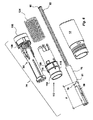
図面に示される実施形態は、ハウジング、より具体的には図1の一般的に管状の近位ハウジング部分10と、一般的に管状の遠位ハウジング部分12とを備える。ハウジング部分は、ハウジング部分を互いに接続するための取付要素とともに配置される。示される実施形態では取付要素は、図2の、遠位ハウジング部分12の近位領域の外側の表面上の周辺の畝部16と相互接続する、近位ハウジング部分10の遠位領域の内面上の、周辺の溝14を備える。しかしながら、いくつか例を挙げるとスレッド、バヨネットコネクタ、スナップインコネクタといった他の種類の取付要素もまた使用されてもよい。
DETAILED DESCRIPTION OF THE INVENTION The embodiment shown in the drawings comprises a housing, more specifically the generally tubular
近位ハウジング部分10は、図2の医薬品容器20を見るための、開口部または窓部18とともに配置され、幾分狭い近位端を有する。医薬品容器は、一般的に管状であり、好ましくはガラスまたはクリアプラスチックといった透過性の材料から作られる。図5のストッパ21は医薬品容器本体内部に移動可能に配置される。図2、図3の近位ハウジング部分10の内側に、医薬品送達部材カバー22は、摺動可能に配置される。医薬品送達部材カバー22は、ある直径を有する第1の近位部分24と近位部分のものより大きい直径を有する第2の遠位部分26とを設けられた一般的には管状であり、これらの部分は、図3の中間円錐状の部分28によって接合される。2つの細長い開口部または窓部30は、医薬品送達部材カバー22の対向する側上に、また医薬品容器20を見るために、医薬品送達部材カバー22に沿って配置される。図3の円錐状の部分28の内面上に、遠位に向けられた棚部32が配置される。図3の医薬品送達部材カバー22の遠位端で、2つの開口部34は、互いに対向して配置され、各開口部は幾分内向きに突出している、可撓性の、舌部36とともに配置される。
The
さらに、図3および図5の容器ホルダー38は、一般的に管状の本体の形態で、医薬品送達部材カバー22の内部かつ同軸方向に配置される。容器ホルダー38の近位部分は、より小さな直径の首部分40とともに配置される。首部分40に隣接して、切欠き部42は、横方向に向けられたガイド表面44および近位に向けられた抑え表面45を形成するために、いずれかの側に形成される。これらのガイド表面44は、医薬品送達部材カバー22の窓部30の側表面46と協働し、容器ホルダー38に対する医薬品送達部材カバー22の長手方向の移動を認めながら、回転ロックを2つの部品間に作成する。容器ホルダー38の遠位端は、2つの遠位に向けられた舌部48とともに配置され、各舌部48は開口部50および各開口部50の遠位エッジ上の内向きに傾いた舌部52とともに配置される。容器ホルダー38はさらに、容器ホルダーの内側の壁と容器ホルダー38内部に配置されるべき医薬品容器20との間の空間を得るために、その内面上に図2の径方向に向けられたフランジ54とともに配置される。
In addition, the
図2および図6の動力部74は、ハウジングに相互作用的に接続される、上記動力部は、付勢要素82と、発動すると直線的に近位方向に移動するように配置され、上記医薬品送達部材134を通して医薬品の用量を排出するために上記医薬品容器20に作用するプランジャロッド76とを備える。
The
さらに、図4a、図4bおよび図5の動力部と容器ホルダーとに接続される保持部材56が設けられる。
Furthermore, a holding
プランジャロッド76は、医薬品の排出中にプランジャロッドが移動することができる直線距離を制限するために、上記保持部材上の少なくとも1つの第2の案内係止要素と相互作用するように構成される少なくとも1つの第1の案内係止要素を備え、距離はドーズ量に対応する。
少なくとも1つの第1の案内係止要素は、近位に向けられた抑え表面81を有する長手方向に延びる溝80であり、少なくとも1つの第2の案内係止要素は、図4bの抑え表面を有する遠位に向けられた抑え突出部67を有する図4aの径方向内向きに位置付けられる抑え突出部66であり、これらの機能は以下に説明されるだろう。
The at least one first guiding locking element is a
長手方向に延びる溝80は、プランジャロッドの外側の表面上に配置され、プランジャロッドの近位端から遠位方向にある長さXを延び、近位に向けられた抑え表面81で終端する。保持部材56の抑え表面を有する遠位に向けられた抑え突出部67を有する抑え棚部66は、これらの溝80に収まるように設計され、配置される。
A
図4aおよび図4bの実施形態に示されるように、保持部材56はさらに、その周の周りに配置される環状棚部60を有するリングの形をした本体58と、リングの形をした本体58から突出して、2つの遠位に向けられた部材62の対/組を形成する4つの遠位に向けられた部材62とを備え、各対は、円セグメントの形をした棚部64によって相互接続される。保持部材56は、医薬品容器を固定位置に保持するために容器ホルダー38と協働することを意図される。図5に示されるように、医薬品容器20が容器ホルダー38の遠位端からそれを挿入することによって容器ホルダー38の内部に配置されるとき、医薬品容器20の近位に向けられたショルダー68は、容器ホルダー38の幾分傾いた環状支持表面70に対して静置される。保持部材56は、そして環状棚部60が傾いた舌部52を通過し、保持部材56を遠位方向にロックするように、保持部材56の遠位端内へと押され、図4aの保持部材の近位表面72は、医薬品容器20の遠位に向けられた端部表面73に対して静置される。医薬品容器20は今や、支持表面70と近位表面72との間の長手方向の方向Lでしっかり保持される。
As shown in the embodiment of FIGS. 4 a and 4 b, the retaining
さらに、プランジャロッド76は、使用されるべき医薬品容器本体の内側の直径よりも幾分か小さい外側の直径を有する管として形成される。プランジャロッド76は、ある幅を有する周辺の溝78を有するように配置され、保持部材56の棚部64は、溝78内に配置され収まる形とされる。
Furthermore, the
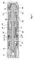
動力部はさらに、図6および図7の主に管状の形状を有し、かつ部分的にプランジャロッドを取り囲むアクチュエータ88と、アクチュエータ88上に同軸方向かつ摺動可能に配置されるアクチュエータスリーブ112と、アクチュエータスリーブとハウジングとの間に配置される圧縮ばね124と、アクチュエータに接続される押しボタン106とを備える。
The power unit further includes an
1つの実施形態によれば、プランジャロッド76の内部に、図8のプランジャロッド76の近位端壁84とアクチュエータ88の近位に向けられた端部壁86との間に螺旋状の圧縮ばね82が配置され、このことは、以下に詳細に説明される。ばね82の内側にばねガイド90が、配置される。
According to one embodiment, a helical compression spring is located within the
図7の、いくつかの長手方向に向けられた切欠き部98は、可撓性の舌部100を形成するために、アクチュエータ88の近位部分に配置される。その近位端において、各可撓性の舌部100は傾いた遷移表面92を備え、これは拡大された直径を有するバンドの形をした部分94と、図8に見られるように保持部材の棚部64とともにプランジャロッドの周辺の溝78に内に収まる環状の内向きに向けられた棚部96とをもたらす。アクチュエータ88はさらに、2つの抑え棚部102を設けられ、これらは、両側上の外側の表面から径方向外側に向けられる。アクチュエータ88の遠位端は、図6の押しボタン106ための、取付ポスト104とともにに配置される。押しボタン106は、図6および図8の近位に向けられた舌部108とともに配置され、そこでは舌部は、図1の遠位ハウジング部分12の内向きに配置される棚部110と相互作用する。
Several longitudinally oriented
アクチュエータ88の同軸方向に外側に、図6および図8のアクチュエータスリーブ112が、摺動可能に配置され、また一般的に管状の形態である。それは、その外側の表面上の棚部116で終端する円錐状の部分114を有する前方端部を備える。棚部116からある距離で、第1の環状リング118は、外側の表面上に配置される。第2の環状リング120はまた、棚部116からさらなる距離で配置される。アクチュエータスリーブ112の遠位端は一般的に長方形の形状の2つの対向して配置される切欠き部122とともに配置され、そこでは幅はアクチュエータ88の抑え棚部102の幅に対応する。医薬品送達部材カバーロック機構内に備えられる図8の長手方向に延びるリブ123は、アクチュエータスリーブ112の内面上に配置され、その機能は、以下に説明されるだろう。圧縮ばね124は、以下で医薬品送達部材カバーばねとも称され、図8に示されるようにアクチュエータ88を取り囲む。
The
近位ハウジング部分10の近位端で、図2および図9の針保護キャップグラバー126は、一般的に管状の形状を有して配置される。それは、医薬品送達部材カバー22の近位部分内に挿入され、そこで摩擦によって保持される。キャップグラバー126の内側に、図9の金属リング12が、近位端に向かって幾分内向きに向けられ鋭くとがった舌部130を有して配置され、図5の医薬品送達部材シース132内に把持することを、意図して設計され、医薬品容器20の注射針134といった医薬品送達部材134を取り囲み保護している。
At the proximal end of the
装置は、以下のように機能するように設計される。装置が、意図されるユーザにそれを送達する前に準備されるときに、装置の近位部分は、医薬品容器20を有して組み立てられる。医薬品容器はこのため、その遠位端から容器ホルダー38内に配置され、容器ホルダー38は好ましくは、医薬品容器20の近位に向けられたショルダー68が医薬品容器の支持表面70に接するまで医薬品容器が容器ホルダー内に摺動するように保持される。容器ホルダー38は次いで、そのガイド表面44が、医薬品送達部材カバー22の切欠き部30の側表面46に接する医薬品送達部材カバー22内に配置される。そして、このアセンブリは、近位ハウジング部分10内に遠位方向から配置される。
The device is designed to function as follows. When the device is prepared before delivering it to the intended user, the proximal portion of the device is assembled with the
動力部74は、近位部分から別々に組み立てられる。圧縮ばね82は、アクチュエータ88の舌部100の内向きに向けられた棚部96が、図8のプランジャロッド76の溝78内に位置するまで、プランジャロッド76が、アクチュエータ88内に遠位方向に押される点で、張力をかけられる。プランジャロッド76を有するアクチュエータ88は、そしてアクチュエータスリーブ112内に遠位方向に押され、このことは舌部100が外側に移動することを防止する。さらに、保持部材56の棚部64はまた、図8に示されるように溝78内に配置される。組み立てられた部品は、そして遠位ハウジング部分12内に近位方向から押される。そして押しボタン106は、アクチュエータ88の取付ポスト104に接続される。
The
動力部74は今や、上述のようにその組み立てられた部品を有する近位ハウジング部分の遠位端に接続される。これは保持部材56の環状棚部60が容器ホルダーの内向きに向けられた舌部52を通過することを引き起こし、医薬品容器は今や、しっかりとロックされる。さらに、医薬品送達部材カバー22の可撓性の舌部36は、アクチュエータスリーブ112の環状棚部116を通過し、図8の2つの部品をともにロックする。最後に、近位ハウジング部分10上の溝14は、図8の遠位ハウジング部分12の畝部16と係合し、2つのハウジング部分をともにロックするだろう。医薬品送達部材保護キャップグラバー126は、装置の近位端内に挿入される。装置は、今や使用する準備ができている。
The
たとえば注射などの送達が実行されるべきとき、医薬品送達部材保護キャップグラバー126は、装置の近位端から離れて近位方向に引っ張られる。これは鋭くとがった舌部130がゴム医薬品送達部材シース132内に押され、それを医薬品送達部材134から除去することを引き起こす。装置の近位端は、そして送達部位に対して押されることができ、医薬品送達部材カバー22の幾分突出している近位端は、アクチュエータスリーブ112の第2の環状リング120と遠位ハウジング部分12の内部に固定された支持表面との間で働く医薬品送達部材カバーばね124の力に反して、図10aのようにハウジング内に押される。医薬品送達部材カバー22の遠位に向けられた端部表面は、アクチュエータスリーブ112の第1の環状リング118と接し、医薬品送達部材カバー22の遠位方向内の移動は、アクチュエータスリーブ112が遠位方向に移動することを引き起こし、バンドの形をした部分94の一部は、図10bに示されるようにアクチュエータスリーブ112の円錐状の部分114の外側に配置されるだろう。
When delivery, such as injection, is to be performed, the pharmaceutical delivery member
たとえば注射などの穿通および送達が発動するとき、ユーザは、単に図11aの押しボタン106を押すにすぎない。押しボタン106の近位に向けられた舌部108はそして内面の棚部110に対して働き、ボタンの初期抵抗を作成し、そしてこれは、ボタンが遠位ハウジング部分内部に移動されながら舌部108が内向きに曲がるときに克服される。これはアクチュエータ88が近位方向に移動されることを引き起こし、バンドの形をした部分94は、完全に図11bのアクチュエータスリーブ112から外へ移動される。アクチュエータ88の舌部100の弾力のある特性は、棚部96がプランジャロッド76の溝78から移動することを引き起こし、そしてそれは、ばね82が原因で自由に移動する。
When penetration and delivery, such as injection, is triggered, the user simply presses the
圧縮ばね82の力は、プランジャロッド76に医薬品容器20のストッパ21上を押させる。しかしストッパ21と容器壁との間の摩擦と、医薬品容器内の液体の非圧縮性および医薬品送達部材134を通る非常に小さな流路とが原因で、力は医薬品容器20を前に向かって容器ホルダー38および保持部材56とともに押し、これにより図12aのたとえば針といった医薬品送達部材134は患者の皮膚を穿孔するだろう。さらに、アクチュエータの舌部100が外側に曲げられるので、アクチュエータスリーブ112は、図12bに示されるように、バンドの形をした部分94によって長手方向の位置に保持される。
棚部96が今やプランジャロッド76の外側の表面に接するために、舌部100は内向きに曲がることができない。
The force of the
Because the
穿通は、容器ホルダー38の切欠き部42の近位に向けられた抑え表面45が医薬品送達部材カバー22の内面上の棚部32に当接するときに止まり、容器ホルダー38と医薬品容器20と保持部材56との移動が停止する。圧縮ばね82からの力は、今やプランジャロッド76を動かし、これにより医薬品容器20の内部の近位方向のストッパ21および液体医薬品は、患者内に送達される。
The penetration stops when the restraining
プランジャロッド76の移動はまた、保持部材56の遠位に向けられた抑え突出部67をプランジャロッド76の溝80内に摺動させることを引き起こす。送達はそして遠位に向けられた抑え突出部67の抑え表面が溝80の近位に向けられた抑え表面81に到達するときに停止し、図13および図14のプランジャロッド76の移動を有効に停止させる。図13aに示されるように、プランジャロッドは、ストッパ21が医薬品容器本体の近位端に到達する前に良好に停止する。このため説明された長さXは、患者内に送達されるべき医薬品の意図される量に応じて変更されてもよいということが理解される。装置はこのため、送達されるべき医薬品の体積を変更するために溝の異なる長さを有する異なるプランジャロッドを使用することができる。残りの部品はそして、体積を変更するために変更または変形されなくてもよい。
The movement of the
プランジャロッド76がこの距離を動かされたときに、その遠位端はアクチュエータの棚部96を通過しており、舌部100は、今や図15の内向きに自由に移動することができる。これはまたアクチュエータスリーブ112を解放し、医薬品送達部材カバーばね124が、アクチュエータスリーブ112に作用しているので、それは、近位方向に促される。装置が送達部位から除去されるとき、医薬品送達部材カバーばね124の力は、アクチュエータスリーブ112を押す。このため、医薬品送達部材カバー22はそれに近位方向で接続され、医薬品送達部材カバー22は、装置の近位端外に押され、医薬品送達部材134を囲む。アクチュエータスリーブ112の移動は、アクチュエータ88のバンドの形をした部分94が、図15のアクチュエータスリーブ112の内面上のリブ123を通過することを引き起こす。リブ123がアクチュエータ88のバンドの形をした部分94の前方端部に当接するだろうために、これらのリブ123は、医薬品送達部材カバー22を装置内に押し戻すためのいずれの試みをも防ぐ。医薬品送達部材カバー22は、このためロックされ、意図せずに針が刺さることを防止する。
When the
これは、上述しかつ図面に示した実施例が単に本発明の非限定的な例であり、それは特許請求の範囲内で多くの方法で変形することができるとみなされるべきであることを理解すべきである。 It is understood that the embodiments described above and shown in the drawings are merely non-limiting examples of the invention and that it should be considered that it can be modified in many ways within the scope of the claims. Should.
Claims (11)
前記ハウジングに相互作用的に接続される動力部(74)を備え、前記動力部(74)は、付勢要素(82)と、医薬品の用量を前記医薬品送達部材(134)を通して排出するために、発動されると、近位方向に直線的に移動するように配置され、かつ前記医薬品容器(20)に作用するプランジャロッド(76)とを備え、前記薬剤送達装置はさらに、
前記動力部および前記容器ホルダーに対して接続される保持部材(56)とを備え、
前記プランジャロッドは、少なくとも1つの第1の案内係止要素を備え、前記第1の案内係止要素は、医薬品の排出中に前記プランジャロッド(76)が移動することができる前記直線距離を制限するために、前記保持部材上の少なくとも1つの第2の案内係止要素に相互作用するように構成され、前記距離は、ドーズ量に対応することを特徴とする、薬剤送達装置。 A drug delivery device comprising a housing (10, 12), the housing (10, 12) being arranged to receive a container holder (38) having a pharmaceutical container (20); The drug container (20) comprises a drug delivery member (134), the drug delivery device further comprising:
A power portion (74) interactively connected to the housing, the power portion (74) for urging the drug dose through the biasing element (82) and the drug delivery member (134); A plunger rod (76) that, when activated, is arranged to move linearly in a proximal direction and acts on the drug container (20), the drug delivery device further comprising:
A holding member (56) connected to the power unit and the container holder,
The plunger rod comprises at least one first guide locking element, the first guide locking element limiting the linear distance that the plunger rod (76) can move during the discharge of a medicament. In order to do so, the drug delivery device is configured to interact with at least one second guide locking element on the holding member, the distance corresponding to a dose.
Applications Claiming Priority (3)
| Application Number | Priority Date | Filing Date | Title |
|---|---|---|---|
| SE1450171 | 2014-02-14 | ||
| SE1450171-2 | 2014-02-14 | ||
| PCT/EP2015/051889 WO2015121080A1 (en) | 2014-02-14 | 2015-01-30 | Automatic injection device |
Publications (2)
| Publication Number | Publication Date |
|---|---|
| JP2017508514A true JP2017508514A (en) | 2017-03-30 |
| JP6774877B2 JP6774877B2 (en) | 2020-10-28 |
Family
ID=20299208
Family Applications (1)
| Application Number | Title | Priority Date | Filing Date |
|---|---|---|---|
| JP2016551707A Active JP6774877B2 (en) | 2014-02-14 | 2015-01-30 | Automatic injection device |
Country Status (11)
| Country | Link |
|---|---|
| US (1) | US10398839B2 (en) |
| EP (1) | EP3104909B1 (en) |
| JP (1) | JP6774877B2 (en) |
| KR (1) | KR101892834B1 (en) |
| CN (1) | CN106061529A (en) |
| AU (1) | AU2015217924B2 (en) |
| CA (1) | CA2937812C (en) |
| DK (1) | DK3104909T3 (en) |
| ES (1) | ES2759239T3 (en) |
| TW (1) | TWI569842B (en) |
| WO (1) | WO2015121080A1 (en) |
Families Citing this family (18)
| Publication number | Priority date | Publication date | Assignee | Title |
|---|---|---|---|---|
| US10398839B2 (en) | 2014-02-14 | 2019-09-03 | Shl Medical Ag | Automatic injection device |
| TW201703802A (en) * | 2015-06-03 | 2017-02-01 | 賽諾菲阿凡提斯德意志有限公司 | Syringe support and autoinjector |
| WO2018002314A1 (en) * | 2016-07-01 | 2018-01-04 | Sanofi | Drug delivery device |
| EP3323448A1 (en) * | 2016-11-18 | 2018-05-23 | Carebay Europe Ltd. | Medicament delivery device |
| WO2018166985A1 (en) | 2017-03-13 | 2018-09-20 | Sanofi-Aventis Deutschland Gmbh | Drug delivery device |
| JP1629608S (en) * | 2017-10-25 | 2019-04-15 | ||
| EP3703796A1 (en) | 2017-11-03 | 2020-09-09 | Sanofi | Plunger and drug delivery device |
| JP6959452B2 (en) * | 2018-01-09 | 2021-11-02 | エスエイチエル・メディカル・アーゲー | Support structure |
| CH713129A2 (en) * | 2018-02-15 | 2018-05-15 | Tecpharma Licensing Ag | Connection mechanism for additional module. |
| CN111867659A (en) * | 2018-03-26 | 2020-10-30 | 艾斯曲尔医疗公司 | Medicament container holder |
| US20210338933A1 (en) * | 2018-07-20 | 2021-11-04 | Novo Nordisk A/S | Autoinjection device having dose logging |
| CN110801302B (en) * | 2019-10-23 | 2021-06-22 | 徐州生物工程职业技术学院 | Automatic livestock injector |
| USD988507S1 (en) * | 2019-12-23 | 2023-06-06 | Sanofi | Medical injection device |
| KR102154125B1 (en) * | 2020-03-27 | 2020-09-09 | (주)딥셀라이트 | Ampoule syringe |
| CN116897062A (en) * | 2021-03-01 | 2023-10-17 | 艾斯曲尔医疗公司 | Power unit subassembly |
| WO2023272716A1 (en) * | 2021-07-02 | 2023-01-05 | 嘉兴森迈医疗科技有限公司 | Autoinjector and actuating assembly thereof |
| CN117615806A (en) * | 2021-08-09 | 2024-02-27 | 艾斯曲尔医疗公司 | Method of manufacturing a sub-assembly of a drug delivery device |
| EP4173653A1 (en) * | 2021-10-27 | 2023-05-03 | medmix Switzerland AG | Release mechanism of autoinjector |
Citations (3)
| Publication number | Priority date | Publication date | Assignee | Title |
|---|---|---|---|---|
| US20050101919A1 (en) * | 2003-11-07 | 2005-05-12 | Lennart Brunnberg | Device for an injector |
| WO2012125133A1 (en) * | 2011-03-17 | 2012-09-20 | Becton, Dickinson And Company | Medical injector with ratcheting plunger |
| US20130102971A1 (en) * | 2010-06-24 | 2013-04-25 | Shl Group Ab | Medicament Delivery Device with Braking Means |
Family Cites Families (14)
| Publication number | Priority date | Publication date | Assignee | Title |
|---|---|---|---|---|
| US2648334A (en) * | 1949-10-28 | 1953-08-11 | Turnbull | Hypodermic injection assembly |
| GB1583157A (en) * | 1976-05-07 | 1981-01-21 | Kenova Ab | Syringes |
| GB9219849D0 (en) | 1992-09-19 | 1992-10-28 | Hypoguard Uk Ltd | Device |
| US6083201A (en) * | 1999-01-07 | 2000-07-04 | Mckinley Medical, Llp | Multi-dose infusion pump |
| SE9901366D0 (en) * | 1999-04-16 | 1999-04-16 | Pharmacia & Upjohn Ab | Injector device and method for its operation |
| US7449012B2 (en) * | 2004-08-06 | 2008-11-11 | Meridian Medical Technologies, Inc. | Automatic injector |
| NZ554828A (en) * | 2004-12-06 | 2010-07-30 | Washington Biotech Corp | Medicine injection devices and methods |
| EP1683537A1 (en) | 2005-01-25 | 2006-07-26 | Pfizer Health AB | Injection device for administering a medication liquid |
| PL2445552T3 (en) | 2009-06-24 | 2016-03-31 | Tecpharma Licensing Ag | Administering device having a priming function |
| TWI393578B (en) * | 2009-07-07 | 2013-04-21 | Shl Group Ab | Injection device |
| DK3192548T3 (en) * | 2009-12-07 | 2021-04-19 | Sanofi Aventis Deutschland | DRIVE DEVICE FOR A MEDICINE ADMINISTRATIVE DEVICE AND MEDICINE ADMINISTRATIVE DEVICE |
| TWI421107B (en) | 2011-07-25 | 2014-01-01 | Shl Group Ab | Medicament delivery device |
| US10022506B2 (en) * | 2012-04-11 | 2018-07-17 | Thomas Jefferson University | Hypodermic injection device incorporated in a case for a portable electronic device |
| US10398839B2 (en) | 2014-02-14 | 2019-09-03 | Shl Medical Ag | Automatic injection device |
-
2015
- 2015-01-30 US US15/118,429 patent/US10398839B2/en active Active
- 2015-01-30 EP EP15708124.1A patent/EP3104909B1/en active Active
- 2015-01-30 DK DK15708124T patent/DK3104909T3/en active
- 2015-01-30 CA CA2937812A patent/CA2937812C/en active Active
- 2015-01-30 JP JP2016551707A patent/JP6774877B2/en active Active
- 2015-01-30 CN CN201580008651.8A patent/CN106061529A/en active Pending
- 2015-01-30 AU AU2015217924A patent/AU2015217924B2/en active Active
- 2015-01-30 KR KR1020167022054A patent/KR101892834B1/en active IP Right Grant
- 2015-01-30 WO PCT/EP2015/051889 patent/WO2015121080A1/en active Application Filing
- 2015-01-30 ES ES15708124T patent/ES2759239T3/en active Active
- 2015-02-09 TW TW104104266A patent/TWI569842B/en active
Patent Citations (3)
| Publication number | Priority date | Publication date | Assignee | Title |
|---|---|---|---|---|
| US20050101919A1 (en) * | 2003-11-07 | 2005-05-12 | Lennart Brunnberg | Device for an injector |
| US20130102971A1 (en) * | 2010-06-24 | 2013-04-25 | Shl Group Ab | Medicament Delivery Device with Braking Means |
| WO2012125133A1 (en) * | 2011-03-17 | 2012-09-20 | Becton, Dickinson And Company | Medical injector with ratcheting plunger |
Also Published As
| Publication number | Publication date |
|---|---|
| US10398839B2 (en) | 2019-09-03 |
| ES2759239T3 (en) | 2020-05-08 |
| AU2015217924B2 (en) | 2017-10-26 |
| EP3104909A1 (en) | 2016-12-21 |
| JP6774877B2 (en) | 2020-10-28 |
| EP3104909B1 (en) | 2019-10-09 |
| CA2937812C (en) | 2018-09-11 |
| CN106061529A (en) | 2016-10-26 |
| US20170173264A1 (en) | 2017-06-22 |
| KR20160111418A (en) | 2016-09-26 |
| DK3104909T3 (en) | 2019-10-28 |
| WO2015121080A1 (en) | 2015-08-20 |
| KR101892834B1 (en) | 2018-08-28 |
| TWI569842B (en) | 2017-02-11 |
| TW201600135A (en) | 2016-01-01 |
| AU2015217924A1 (en) | 2016-07-28 |
| CA2937812A1 (en) | 2015-08-20 |
Similar Documents
| Publication | Publication Date | Title |
|---|---|---|
| JP6774877B2 (en) | Automatic injection device | |
| US11484667B2 (en) | Medicament delivery device | |
| US11141536B2 (en) | Injection device with dosing control means | |
| US9220847B2 (en) | Medicament delivery device | |
| US9925336B2 (en) | Cassette for a hidden injection needle | |
| JP6426399B2 (en) | Safe prefilled pen needle | |
| JP6138129B2 (en) | Injection device | |
| JP2020501675A (en) | Safety needle device | |
| JP2019500991A (en) | Automatic syringe with cartridge retention system | |
| JP2007510501A (en) | Safety shield system for syringes | |
| JP6567687B2 (en) | Automatic syringe drive mechanism | |
| JP2016500321A (en) | Drug delivery device | |
| JP2018537251A (en) | Drug delivery device | |
| JP2019535411A (en) | Drug delivery device suitable for long-term storage | |
| JP2022549268A (en) | Needle assembly with needle shield and plug |
Legal Events
| Date | Code | Title | Description |
|---|---|---|---|
| A621 | Written request for application examination |
Free format text: JAPANESE INTERMEDIATE CODE: A621 Effective date: 20161011 |
|
| A977 | Report on retrieval |
Free format text: JAPANESE INTERMEDIATE CODE: A971007 Effective date: 20170721 |
|
| A131 | Notification of reasons for refusal |
Free format text: JAPANESE INTERMEDIATE CODE: A131 Effective date: 20170801 |
|
| A131 | Notification of reasons for refusal |
Free format text: JAPANESE INTERMEDIATE CODE: A131 Effective date: 20180410 |
|
| A02 | Decision of refusal |
Free format text: JAPANESE INTERMEDIATE CODE: A02 Effective date: 20181127 |
|
| A521 | Request for written amendment filed |
Free format text: JAPANESE INTERMEDIATE CODE: A523 Effective date: 20190326 |
|
| A911 | Transfer to examiner for re-examination before appeal (zenchi) |
Free format text: JAPANESE INTERMEDIATE CODE: A911 Effective date: 20190405 |
|
| A711 | Notification of change in applicant |
Free format text: JAPANESE INTERMEDIATE CODE: A711 Effective date: 20190419 |
|
| A521 | Request for written amendment filed |
Free format text: JAPANESE INTERMEDIATE CODE: A821 Effective date: 20190419 |
|
| A912 | Re-examination (zenchi) completed and case transferred to appeal board |
Free format text: JAPANESE INTERMEDIATE CODE: A912 Effective date: 20190607 |
|
| A521 | Request for written amendment filed |
Free format text: JAPANESE INTERMEDIATE CODE: A523 Effective date: 20200611 |
|
| A521 | Request for written amendment filed |
Free format text: JAPANESE INTERMEDIATE CODE: A523 Effective date: 20200714 |
|
| A61 | First payment of annual fees (during grant procedure) |
Free format text: JAPANESE INTERMEDIATE CODE: A61 Effective date: 20201005 |
|
| R150 | Certificate of patent or registration of utility model |
Ref document number: 6774877 Country of ref document: JP Free format text: JAPANESE INTERMEDIATE CODE: R150 |
|
| R250 | Receipt of annual fees |
Free format text: JAPANESE INTERMEDIATE CODE: R250 |