JP2017507803A - Multilayer composite article - Google Patents
Multilayer composite article Download PDFInfo
- Publication number
- JP2017507803A JP2017507803A JP2016541307A JP2016541307A JP2017507803A JP 2017507803 A JP2017507803 A JP 2017507803A JP 2016541307 A JP2016541307 A JP 2016541307A JP 2016541307 A JP2016541307 A JP 2016541307A JP 2017507803 A JP2017507803 A JP 2017507803A
- Authority
- JP
- Japan
- Prior art keywords
- group
- substrate
- monomer unit
- divalent
- polymer
- Prior art date
- Legal status (The legal status is an assumption and is not a legal conclusion. Google has not performed a legal analysis and makes no representation as to the accuracy of the status listed.)
- Pending
Links
- 239000002131 composite material Substances 0.000 title claims abstract description 64
- 239000000758 substrate Substances 0.000 claims abstract description 82
- 239000000178 monomer Substances 0.000 claims abstract description 79
- 238000000576 coating method Methods 0.000 claims abstract description 51
- 239000002105 nanoparticle Substances 0.000 claims abstract description 49
- 239000011248 coating agent Substances 0.000 claims abstract description 48
- 230000003667 anti-reflective effect Effects 0.000 claims abstract description 46
- 125000004432 carbon atom Chemical group C* 0.000 claims abstract description 38
- 229920000642 polymer Polymers 0.000 claims abstract description 37
- XPBBUZJBQWWFFJ-UHFFFAOYSA-N fluorosilane Chemical compound [SiH3]F XPBBUZJBQWWFFJ-UHFFFAOYSA-N 0.000 claims abstract description 32
- 125000002496 methyl group Chemical group [H]C([H])([H])* 0.000 claims abstract description 27
- 229910052809 inorganic oxide Inorganic materials 0.000 claims abstract description 16
- 125000001931 aliphatic group Chemical group 0.000 claims abstract description 14
- 229920005596 polymer binder Polymers 0.000 claims abstract description 14
- 239000002491 polymer binding agent Substances 0.000 claims abstract description 14
- 125000002023 trifluoromethyl group Chemical group FC(F)(F)* 0.000 claims abstract description 13
- 125000001183 hydrocarbyl group Chemical group 0.000 claims abstract description 12
- 125000005010 perfluoroalkyl group Chemical group 0.000 claims abstract description 12
- 239000000203 mixture Substances 0.000 claims description 40
- VYPSYNLAJGMNEJ-UHFFFAOYSA-N Silicium dioxide Chemical compound O=[Si]=O VYPSYNLAJGMNEJ-UHFFFAOYSA-N 0.000 claims description 36
- 238000005299 abrasion Methods 0.000 claims description 25
- 238000004519 manufacturing process Methods 0.000 claims description 24
- 238000000034 method Methods 0.000 claims description 24
- MCMNRKCIXSYSNV-UHFFFAOYSA-N Zirconium dioxide Chemical compound O=[Zr]=O MCMNRKCIXSYSNV-UHFFFAOYSA-N 0.000 claims description 17
- 239000000377 silicon dioxide Substances 0.000 claims description 15
- 229910052731 fluorine Inorganic materials 0.000 claims description 10
- 150000001336 alkenes Chemical class 0.000 claims description 9
- 229920000058 polyacrylate Polymers 0.000 claims description 9
- 239000002985 plastic film Substances 0.000 claims description 5
- 229920006255 plastic film Polymers 0.000 claims description 5
- 125000001453 quaternary ammonium group Chemical group 0.000 claims description 5
- 230000008569 process Effects 0.000 claims description 3
- 230000001012 protector Effects 0.000 claims description 3
- 239000000463 material Substances 0.000 abstract description 13
- 239000010410 layer Substances 0.000 description 91
- 239000000243 solution Substances 0.000 description 23
- 239000002245 particle Substances 0.000 description 22
- 238000012360 testing method Methods 0.000 description 21
- 230000000052 comparative effect Effects 0.000 description 16
- 239000000523 sample Substances 0.000 description 16
- 230000003746 surface roughness Effects 0.000 description 15
- ARXJGSRGQADJSQ-UHFFFAOYSA-N 1-methoxypropan-2-ol Chemical compound COCC(C)O ARXJGSRGQADJSQ-UHFFFAOYSA-N 0.000 description 14
- 239000008199 coating composition Substances 0.000 description 12
- -1 acryl Chemical group 0.000 description 11
- XLYOFNOQVPJJNP-UHFFFAOYSA-N water Substances O XLYOFNOQVPJJNP-UHFFFAOYSA-N 0.000 description 11
- 239000011230 binding agent Substances 0.000 description 10
- 239000011247 coating layer Substances 0.000 description 10
- 230000003287 optical effect Effects 0.000 description 10
- 230000003068 static effect Effects 0.000 description 9
- 239000006117 anti-reflective coating Substances 0.000 description 8
- 238000002156 mixing Methods 0.000 description 8
- 239000010954 inorganic particle Substances 0.000 description 7
- 239000007787 solid Substances 0.000 description 7
- IJGRMHOSHXDMSA-UHFFFAOYSA-N Atomic nitrogen Chemical compound N#N IJGRMHOSHXDMSA-UHFFFAOYSA-N 0.000 description 6
- 238000001723 curing Methods 0.000 description 6
- 230000005611 electricity Effects 0.000 description 6
- 238000005259 measurement Methods 0.000 description 6
- 238000010998 test method Methods 0.000 description 6
- KFZMGEQAYNKOFK-UHFFFAOYSA-N Isopropanol Chemical compound CC(C)O KFZMGEQAYNKOFK-UHFFFAOYSA-N 0.000 description 5
- 125000003545 alkoxy group Chemical group 0.000 description 5
- 230000005540 biological transmission Effects 0.000 description 5
- 238000006243 chemical reaction Methods 0.000 description 5
- 239000003431 cross linking reagent Substances 0.000 description 5
- 238000003618 dip coating Methods 0.000 description 5
- 125000000524 functional group Chemical group 0.000 description 5
- 239000002904 solvent Substances 0.000 description 5
- 238000012876 topography Methods 0.000 description 5
- NIXOWILDQLNWCW-UHFFFAOYSA-M Acrylate Chemical compound [O-]C(=O)C=C NIXOWILDQLNWCW-UHFFFAOYSA-M 0.000 description 4
- 125000004423 acyloxy group Chemical group 0.000 description 4
- 238000006482 condensation reaction Methods 0.000 description 4
- 238000004132 cross linking Methods 0.000 description 4
- 238000009826 distribution Methods 0.000 description 4
- 125000002887 hydroxy group Chemical group [H]O* 0.000 description 4
- 239000003607 modifier Substances 0.000 description 4
- 239000011164 primary particle Substances 0.000 description 4
- 150000003254 radicals Chemical class 0.000 description 4
- 238000001228 spectrum Methods 0.000 description 4
- 239000000126 substance Substances 0.000 description 4
- 125000000391 vinyl group Chemical group [H]C([*])=C([H])[H] 0.000 description 4
- ZWEHNKRNPOVVGH-UHFFFAOYSA-N 2-Butanone Chemical compound CCC(C)=O ZWEHNKRNPOVVGH-UHFFFAOYSA-N 0.000 description 3
- CSCPPACGZOOCGX-UHFFFAOYSA-N Acetone Chemical compound CC(C)=O CSCPPACGZOOCGX-UHFFFAOYSA-N 0.000 description 3
- UHOVQNZJYSORNB-UHFFFAOYSA-N Benzene Chemical compound C1=CC=CC=C1 UHOVQNZJYSORNB-UHFFFAOYSA-N 0.000 description 3
- OKTJSMMVPCPJKN-UHFFFAOYSA-N Carbon Chemical compound [C] OKTJSMMVPCPJKN-UHFFFAOYSA-N 0.000 description 3
- RTZKZFJDLAIYFH-UHFFFAOYSA-N Diethyl ether Chemical compound CCOCC RTZKZFJDLAIYFH-UHFFFAOYSA-N 0.000 description 3
- LFQSCWFLJHTTHZ-UHFFFAOYSA-N Ethanol Chemical compound CCO LFQSCWFLJHTTHZ-UHFFFAOYSA-N 0.000 description 3
- XEKOWRVHYACXOJ-UHFFFAOYSA-N Ethyl acetate Chemical compound CCOC(C)=O XEKOWRVHYACXOJ-UHFFFAOYSA-N 0.000 description 3
- ZMXDDKWLCZADIW-UHFFFAOYSA-N N,N-Dimethylformamide Chemical compound CN(C)C=O ZMXDDKWLCZADIW-UHFFFAOYSA-N 0.000 description 3
- YXFVVABEGXRONW-UHFFFAOYSA-N Toluene Chemical compound CC1=CC=CC=C1 YXFVVABEGXRONW-UHFFFAOYSA-N 0.000 description 3
- 150000001252 acrylic acid derivatives Chemical class 0.000 description 3
- 125000000217 alkyl group Chemical group 0.000 description 3
- 125000003118 aryl group Chemical group 0.000 description 3
- 229910052799 carbon Inorganic materials 0.000 description 3
- 230000000694 effects Effects 0.000 description 3
- VLKZOEOYAKHREP-UHFFFAOYSA-N n-Hexane Chemical compound CCCCCC VLKZOEOYAKHREP-UHFFFAOYSA-N 0.000 description 3
- 229910052757 nitrogen Inorganic materials 0.000 description 3
- 229920001187 thermosetting polymer Polymers 0.000 description 3
- BPSIOYPQMFLKFR-UHFFFAOYSA-N trimethoxy-[3-(oxiran-2-ylmethoxy)propyl]silane Chemical compound CO[Si](OC)(OC)CCCOCC1CO1 BPSIOYPQMFLKFR-UHFFFAOYSA-N 0.000 description 3
- 229920002554 vinyl polymer Polymers 0.000 description 3
- GETTZEONDQJALK-UHFFFAOYSA-N (trifluoromethyl)benzene Chemical compound FC(F)(F)C1=CC=CC=C1 GETTZEONDQJALK-UHFFFAOYSA-N 0.000 description 2
- OSXPVFSMSBQPBU-UHFFFAOYSA-N 2-(2-carboxyethoxycarbonyl)benzoic acid Chemical compound OC(=O)CCOC(=O)C1=CC=CC=C1C(O)=O OSXPVFSMSBQPBU-UHFFFAOYSA-N 0.000 description 2
- KWOLFJPFCHCOCG-UHFFFAOYSA-N Acetophenone Chemical compound CC(=O)C1=CC=CC=C1 KWOLFJPFCHCOCG-UHFFFAOYSA-N 0.000 description 2
- IAZDPXIOMUYVGZ-UHFFFAOYSA-N Dimethylsulphoxide Chemical compound CS(C)=O IAZDPXIOMUYVGZ-UHFFFAOYSA-N 0.000 description 2
- VEXZGXHMUGYJMC-UHFFFAOYSA-N Hydrochloric acid Chemical compound Cl VEXZGXHMUGYJMC-UHFFFAOYSA-N 0.000 description 2
- IMNFDUFMRHMDMM-UHFFFAOYSA-N N-Heptane Chemical compound CCCCCCC IMNFDUFMRHMDMM-UHFFFAOYSA-N 0.000 description 2
- GWEVSGVZZGPLCZ-UHFFFAOYSA-N Titan oxide Chemical compound O=[Ti]=O GWEVSGVZZGPLCZ-UHFFFAOYSA-N 0.000 description 2
- 238000004458 analytical method Methods 0.000 description 2
- 230000003373 anti-fouling effect Effects 0.000 description 2
- QVGXLLKOCUKJST-UHFFFAOYSA-N atomic oxygen Chemical compound [O] QVGXLLKOCUKJST-UHFFFAOYSA-N 0.000 description 2
- 230000015572 biosynthetic process Effects 0.000 description 2
- 229920006217 cellulose acetate butyrate Polymers 0.000 description 2
- 150000001875 compounds Chemical class 0.000 description 2
- 238000010276 construction Methods 0.000 description 2
- 238000007766 curtain coating Methods 0.000 description 2
- 125000004122 cyclic group Chemical group 0.000 description 2
- 238000007607 die coating method Methods 0.000 description 2
- 230000003670 easy-to-clean Effects 0.000 description 2
- 239000011521 glass Substances 0.000 description 2
- 125000004435 hydrogen atom Chemical group [H]* 0.000 description 2
- 238000003384 imaging method Methods 0.000 description 2
- 238000002347 injection Methods 0.000 description 2
- 239000007924 injection Substances 0.000 description 2
- 239000003550 marker Substances 0.000 description 2
- 238000000691 measurement method Methods 0.000 description 2
- JDSHMPZPIAZGSV-UHFFFAOYSA-N melamine Chemical compound NC1=NC(N)=NC(N)=N1 JDSHMPZPIAZGSV-UHFFFAOYSA-N 0.000 description 2
- 239000002184 metal Substances 0.000 description 2
- 238000012986 modification Methods 0.000 description 2
- 230000004048 modification Effects 0.000 description 2
- 229910052760 oxygen Inorganic materials 0.000 description 2
- 239000001301 oxygen Substances 0.000 description 2
- XNLICIUVMPYHGG-UHFFFAOYSA-N pentan-2-one Chemical compound CCCC(C)=O XNLICIUVMPYHGG-UHFFFAOYSA-N 0.000 description 2
- 229920003023 plastic Polymers 0.000 description 2
- 239000004033 plastic Substances 0.000 description 2
- 229920000515 polycarbonate Polymers 0.000 description 2
- 239000004417 polycarbonate Substances 0.000 description 2
- 229920006289 polycarbonate film Polymers 0.000 description 2
- 229920000139 polyethylene terephthalate Polymers 0.000 description 2
- 239000005020 polyethylene terephthalate Substances 0.000 description 2
- 230000000379 polymerizing effect Effects 0.000 description 2
- 239000004814 polyurethane Substances 0.000 description 2
- 229920002635 polyurethane Polymers 0.000 description 2
- 239000000047 product Substances 0.000 description 2
- 239000011541 reaction mixture Substances 0.000 description 2
- 238000002310 reflectometry Methods 0.000 description 2
- 238000007151 ring opening polymerisation reaction Methods 0.000 description 2
- 238000010079 rubber tapping Methods 0.000 description 2
- 150000004756 silanes Chemical class 0.000 description 2
- 238000005245 sintering Methods 0.000 description 2
- 239000008247 solid mixture Substances 0.000 description 2
- 238000004528 spin coating Methods 0.000 description 2
- 238000003786 synthesis reaction Methods 0.000 description 2
- PSGCQDPCAWOCSH-UHFFFAOYSA-N (4,7,7-trimethyl-3-bicyclo[2.2.1]heptanyl) prop-2-enoate Chemical compound C1CC2(C)C(OC(=O)C=C)CC1C2(C)C PSGCQDPCAWOCSH-UHFFFAOYSA-N 0.000 description 1
- FFWDBWLGIPNATR-UHFFFAOYSA-N (4-acetylphenyl) prop-2-enoate Chemical compound CC(=O)C1=CC=C(OC(=O)C=C)C=C1 FFWDBWLGIPNATR-UHFFFAOYSA-N 0.000 description 1
- LTYBJDPMCPTGEE-UHFFFAOYSA-N (4-benzoylphenyl) prop-2-enoate Chemical compound C1=CC(OC(=O)C=C)=CC=C1C(=O)C1=CC=CC=C1 LTYBJDPMCPTGEE-UHFFFAOYSA-N 0.000 description 1
- AVGQTJUPLKNPQP-UHFFFAOYSA-N 1,1,1-trichloropropane Chemical compound CCC(Cl)(Cl)Cl AVGQTJUPLKNPQP-UHFFFAOYSA-N 0.000 description 1
- WSLDOOZREJYCGB-UHFFFAOYSA-N 1,2-Dichloroethane Chemical group ClCCCl WSLDOOZREJYCGB-UHFFFAOYSA-N 0.000 description 1
- QBDUXCMCGRDEAN-UHFFFAOYSA-N 2-(4-benzoylphenoxy)ethyl prop-2-enoate Chemical compound C1=CC(OCCOC(=O)C=C)=CC=C1C(=O)C1=CC=CC=C1 QBDUXCMCGRDEAN-UHFFFAOYSA-N 0.000 description 1
- XDLMVUHYZWKMMD-UHFFFAOYSA-N 3-trimethoxysilylpropyl 2-methylprop-2-enoate Chemical compound CO[Si](OC)(OC)CCCOC(=O)C(C)=C XDLMVUHYZWKMMD-UHFFFAOYSA-N 0.000 description 1
- 101150106709 ARC1 gene Proteins 0.000 description 1
- 239000005047 Allyltrichlorosilane Substances 0.000 description 1
- 101100013575 Arabidopsis thaliana FTSHI1 gene Proteins 0.000 description 1
- 101100077113 Arabidopsis thaliana MIND1 gene Proteins 0.000 description 1
- 238000012935 Averaging Methods 0.000 description 1
- DKPFZGUDAPQIHT-UHFFFAOYSA-N Butyl acetate Natural products CCCCOC(C)=O DKPFZGUDAPQIHT-UHFFFAOYSA-N 0.000 description 1
- 239000004971 Cross linker Substances 0.000 description 1
- XDTMQSROBMDMFD-UHFFFAOYSA-N Cyclohexane Chemical compound C1CCCCC1 XDTMQSROBMDMFD-UHFFFAOYSA-N 0.000 description 1
- 229920003270 Cymel® Polymers 0.000 description 1
- RWSOTUBLDIXVET-UHFFFAOYSA-N Dihydrogen sulfide Chemical class S RWSOTUBLDIXVET-UHFFFAOYSA-N 0.000 description 1
- ZAFNJMIOTHYJRJ-UHFFFAOYSA-N Diisopropyl ether Chemical compound CC(C)OC(C)C ZAFNJMIOTHYJRJ-UHFFFAOYSA-N 0.000 description 1
- XTHFKEDIFFGKHM-UHFFFAOYSA-N Dimethoxyethane Chemical compound COCCOC XTHFKEDIFFGKHM-UHFFFAOYSA-N 0.000 description 1
- 239000004593 Epoxy Substances 0.000 description 1
- 229920000877 Melamine resin Polymers 0.000 description 1
- LSDPWZHWYPCBBB-UHFFFAOYSA-N Methanethiol Chemical compound SC LSDPWZHWYPCBBB-UHFFFAOYSA-N 0.000 description 1
- NTIZESTWPVYFNL-UHFFFAOYSA-N Methyl isobutyl ketone Chemical compound CC(C)CC(C)=O NTIZESTWPVYFNL-UHFFFAOYSA-N 0.000 description 1
- UIHCLUNTQKBZGK-UHFFFAOYSA-N Methyl isobutyl ketone Natural products CCC(C)C(C)=O UIHCLUNTQKBZGK-UHFFFAOYSA-N 0.000 description 1
- 229920001410 Microfiber Polymers 0.000 description 1
- 101000984025 Mus musculus Cadherin-1 Proteins 0.000 description 1
- FXHOOIRPVKKKFG-UHFFFAOYSA-N N,N-Dimethylacetamide Chemical compound CN(C)C(C)=O FXHOOIRPVKKKFG-UHFFFAOYSA-N 0.000 description 1
- CTQNGGLPUBDAKN-UHFFFAOYSA-N O-Xylene Chemical compound CC1=CC=CC=C1C CTQNGGLPUBDAKN-UHFFFAOYSA-N 0.000 description 1
- 239000004952 Polyamide Substances 0.000 description 1
- 239000004642 Polyimide Substances 0.000 description 1
- BLRPTPMANUNPDV-UHFFFAOYSA-N Silane Chemical compound [SiH4] BLRPTPMANUNPDV-UHFFFAOYSA-N 0.000 description 1
- XUIMIQQOPSSXEZ-UHFFFAOYSA-N Silicon Chemical group [Si] XUIMIQQOPSSXEZ-UHFFFAOYSA-N 0.000 description 1
- 229910002808 Si–O–Si Inorganic materials 0.000 description 1
- NINIDFKCEFEMDL-UHFFFAOYSA-N Sulfur Chemical compound [S] NINIDFKCEFEMDL-UHFFFAOYSA-N 0.000 description 1
- 229910010413 TiO 2 Inorganic materials 0.000 description 1
- 238000003848 UV Light-Curing Methods 0.000 description 1
- QYKIQEUNHZKYBP-UHFFFAOYSA-N Vinyl ether Chemical class C=COC=C QYKIQEUNHZKYBP-UHFFFAOYSA-N 0.000 description 1
- NOZAQBYNLKNDRT-UHFFFAOYSA-N [diacetyloxy(ethenyl)silyl] acetate Chemical compound CC(=O)O[Si](OC(C)=O)(OC(C)=O)C=C NOZAQBYNLKNDRT-UHFFFAOYSA-N 0.000 description 1
- 239000006096 absorbing agent Substances 0.000 description 1
- 230000002378 acidificating effect Effects 0.000 description 1
- 239000004676 acrylonitrile butadiene styrene Substances 0.000 description 1
- 239000012790 adhesive layer Substances 0.000 description 1
- 239000002671 adjuvant Substances 0.000 description 1
- 238000004220 aggregation Methods 0.000 description 1
- 230000002776 aggregation Effects 0.000 description 1
- 150000001298 alcohols Chemical class 0.000 description 1
- 150000001338 aliphatic hydrocarbons Chemical class 0.000 description 1
- 125000002947 alkylene group Chemical group 0.000 description 1
- HSFWRNGVRCDJHI-UHFFFAOYSA-N alpha-acetylene Natural products C#C HSFWRNGVRCDJHI-UHFFFAOYSA-N 0.000 description 1
- PNEYBMLMFCGWSK-UHFFFAOYSA-N aluminium oxide Inorganic materials [O-2].[O-2].[O-2].[Al+3].[Al+3] PNEYBMLMFCGWSK-UHFFFAOYSA-N 0.000 description 1
- 150000001408 amides Chemical class 0.000 description 1
- PYKYMHQGRFAEBM-UHFFFAOYSA-N anthraquinone Natural products CCC(=O)c1c(O)c2C(=O)C3C(C=CC=C3O)C(=O)c2cc1CC(=O)OC PYKYMHQGRFAEBM-UHFFFAOYSA-N 0.000 description 1
- 150000004056 anthraquinones Chemical class 0.000 description 1
- 239000002518 antifoaming agent Substances 0.000 description 1
- 229910000410 antimony oxide Inorganic materials 0.000 description 1
- 239000003963 antioxidant agent Substances 0.000 description 1
- 239000002216 antistatic agent Substances 0.000 description 1
- 238000013459 approach Methods 0.000 description 1
- 239000003849 aromatic solvent Substances 0.000 description 1
- 239000012298 atmosphere Substances 0.000 description 1
- 239000003139 biocide Substances 0.000 description 1
- 230000001680 brushing effect Effects 0.000 description 1
- CQEYYJKEWSMYFG-UHFFFAOYSA-N butyl acrylate Chemical compound CCCCOC(=O)C=C CQEYYJKEWSMYFG-UHFFFAOYSA-N 0.000 description 1
- 150000001718 carbodiimides Chemical class 0.000 description 1
- 239000003054 catalyst Substances 0.000 description 1
- 239000012986 chain transfer agent Substances 0.000 description 1
- 230000008859 change Effects 0.000 description 1
- 239000007795 chemical reaction product Substances 0.000 description 1
- 239000003795 chemical substances by application Substances 0.000 description 1
- 238000005229 chemical vapour deposition Methods 0.000 description 1
- DMZWVCJEOLBQCZ-UHFFFAOYSA-N chloro(ethenyl)silane Chemical compound Cl[SiH2]C=C DMZWVCJEOLBQCZ-UHFFFAOYSA-N 0.000 description 1
- 238000001246 colloidal dispersion Methods 0.000 description 1
- 239000008119 colloidal silica Substances 0.000 description 1
- 238000009833 condensation Methods 0.000 description 1
- 230000005494 condensation Effects 0.000 description 1
- 229920001940 conductive polymer Polymers 0.000 description 1
- 238000007796 conventional method Methods 0.000 description 1
- 125000000113 cyclohexyl group Chemical group [H]C1([H])C([H])([H])C([H])([H])C([H])(*)C([H])([H])C1([H])[H] 0.000 description 1
- 230000007547 defect Effects 0.000 description 1
- 239000008367 deionised water Substances 0.000 description 1
- 229910021641 deionized water Inorganic materials 0.000 description 1
- 238000009792 diffusion process Methods 0.000 description 1
- SBZXBUIDTXKZTM-UHFFFAOYSA-N diglyme Chemical compound COCCOCCOC SBZXBUIDTXKZTM-UHFFFAOYSA-N 0.000 description 1
- 238000007598 dipping method Methods 0.000 description 1
- 150000002118 epoxides Chemical class 0.000 description 1
- 150000002148 esters Chemical class 0.000 description 1
- FALCQDAWENTNHF-UHFFFAOYSA-N ethenyl(2-methoxyethoxy)silane Chemical compound COCCO[SiH2]C=C FALCQDAWENTNHF-UHFFFAOYSA-N 0.000 description 1
- FWDBOZPQNFPOLF-UHFFFAOYSA-N ethenyl(triethoxy)silane Chemical compound CCO[Si](OCC)(OCC)C=C FWDBOZPQNFPOLF-UHFFFAOYSA-N 0.000 description 1
- NKSJNEHGWDZZQF-UHFFFAOYSA-N ethenyl(trimethoxy)silane Chemical compound CO[Si](OC)(OC)C=C NKSJNEHGWDZZQF-UHFFFAOYSA-N 0.000 description 1
- FEHYCIQPPPQNMI-UHFFFAOYSA-N ethenyl(triphenoxy)silane Chemical compound C=1C=CC=CC=1O[Si](OC=1C=CC=CC=1)(C=C)OC1=CC=CC=C1 FEHYCIQPPPQNMI-UHFFFAOYSA-N 0.000 description 1
- IRTACFOVZDBFEX-UHFFFAOYSA-N ethenyl-diethoxy-ethylsilane Chemical compound CCO[Si](CC)(C=C)OCC IRTACFOVZDBFEX-UHFFFAOYSA-N 0.000 description 1
- MBGQQKKTDDNCSG-UHFFFAOYSA-N ethenyl-diethoxy-methylsilane Chemical compound CCO[Si](C)(C=C)OCC MBGQQKKTDDNCSG-UHFFFAOYSA-N 0.000 description 1
- ZLNAFSPCNATQPQ-UHFFFAOYSA-N ethenyl-dimethoxy-methylsilane Chemical compound CO[Si](C)(OC)C=C ZLNAFSPCNATQPQ-UHFFFAOYSA-N 0.000 description 1
- JEWCZPTVOYXPGG-UHFFFAOYSA-N ethenyl-ethoxy-dimethylsilane Chemical compound CCO[Si](C)(C)C=C JEWCZPTVOYXPGG-UHFFFAOYSA-N 0.000 description 1
- NUFVQEIPPHHQCK-UHFFFAOYSA-N ethenyl-methoxy-dimethylsilane Chemical compound CO[Si](C)(C)C=C NUFVQEIPPHHQCK-UHFFFAOYSA-N 0.000 description 1
- MABAWBWRUSBLKQ-UHFFFAOYSA-N ethenyl-tri(propan-2-yloxy)silane Chemical compound CC(C)O[Si](OC(C)C)(OC(C)C)C=C MABAWBWRUSBLKQ-UHFFFAOYSA-N 0.000 description 1
- XSUJDDNOLKLDLF-UHFFFAOYSA-N ethenyl-tris(3-methoxypropoxy)silane Chemical compound COCCCO[Si](OCCCOC)(OCCCOC)C=C XSUJDDNOLKLDLF-UHFFFAOYSA-N 0.000 description 1
- GBFVZTUQONJGSL-UHFFFAOYSA-N ethenyl-tris(prop-1-en-2-yloxy)silane Chemical compound CC(=C)O[Si](OC(C)=C)(OC(C)=C)C=C GBFVZTUQONJGSL-UHFFFAOYSA-N 0.000 description 1
- BQRPSOKLSZSNAR-UHFFFAOYSA-N ethenyl-tris[(2-methylpropan-2-yl)oxy]silane Chemical compound CC(C)(C)O[Si](OC(C)(C)C)(OC(C)(C)C)C=C BQRPSOKLSZSNAR-UHFFFAOYSA-N 0.000 description 1
- 150000002170 ethers Chemical class 0.000 description 1
- 125000005677 ethinylene group Chemical group [*:2]C#C[*:1] 0.000 description 1
- 125000001495 ethyl group Chemical group [H]C([H])([H])C([H])([H])* 0.000 description 1
- ITAHRPSKCCPKOK-UHFFFAOYSA-N ethyl trimethyl silicate Chemical group CCO[Si](OC)(OC)OC ITAHRPSKCCPKOK-UHFFFAOYSA-N 0.000 description 1
- 230000008020 evaporation Effects 0.000 description 1
- 238000001704 evaporation Methods 0.000 description 1
- 238000007765 extrusion coating Methods 0.000 description 1
- 238000001914 filtration Methods 0.000 description 1
- 239000012467 final product Substances 0.000 description 1
- 239000012530 fluid Substances 0.000 description 1
- 125000001153 fluoro group Chemical group F* 0.000 description 1
- 229910021485 fumed silica Inorganic materials 0.000 description 1
- 238000001879 gelation Methods 0.000 description 1
- VOZRXNHHFUQHIL-UHFFFAOYSA-N glycidyl methacrylate Chemical compound CC(=C)C(=O)OCC1CO1 VOZRXNHHFUQHIL-UHFFFAOYSA-N 0.000 description 1
- 238000000227 grinding Methods 0.000 description 1
- 125000005843 halogen group Chemical group 0.000 description 1
- 238000010438 heat treatment Methods 0.000 description 1
- 125000005842 heteroatom Chemical group 0.000 description 1
- NEXSMEBSBIABKL-UHFFFAOYSA-N hexamethyldisilane Chemical compound C[Si](C)(C)[Si](C)(C)C NEXSMEBSBIABKL-UHFFFAOYSA-N 0.000 description 1
- FUZZWVXGSFPDMH-UHFFFAOYSA-N hexanoic acid Chemical compound CCCCCC(O)=O FUZZWVXGSFPDMH-UHFFFAOYSA-N 0.000 description 1
- 230000007062 hydrolysis Effects 0.000 description 1
- 238000006460 hydrolysis reaction Methods 0.000 description 1
- 238000006459 hydrosilylation reaction Methods 0.000 description 1
- 239000004615 ingredient Substances 0.000 description 1
- 229910010272 inorganic material Inorganic materials 0.000 description 1
- 239000011147 inorganic material Substances 0.000 description 1
- 238000007689 inspection Methods 0.000 description 1
- 230000003993 interaction Effects 0.000 description 1
- 239000011229 interlayer Substances 0.000 description 1
- 125000000959 isobutyl group Chemical group [H]C([H])([H])C([H])(C([H])([H])[H])C([H])([H])* 0.000 description 1
- 239000012948 isocyanate Substances 0.000 description 1
- 150000002576 ketones Chemical class 0.000 description 1
- 239000007788 liquid Substances 0.000 description 1
- 239000000314 lubricant Substances 0.000 description 1
- 230000014759 maintenance of location Effects 0.000 description 1
- 230000001404 mediated effect Effects 0.000 description 1
- 125000005641 methacryl group Chemical group 0.000 description 1
- CERQOIWHTDAKMF-UHFFFAOYSA-M methacrylate group Chemical group C(C(=C)C)(=O)[O-] CERQOIWHTDAKMF-UHFFFAOYSA-M 0.000 description 1
- 239000004005 microsphere Substances 0.000 description 1
- 229910003455 mixed metal oxide Inorganic materials 0.000 description 1
- 239000002991 molded plastic Substances 0.000 description 1
- 125000005246 nonafluorobutyl group Chemical group FC(F)(F)C(F)(F)C(F)(F)C(F)(F)* 0.000 description 1
- 125000000962 organic group Chemical group 0.000 description 1
- 239000011368 organic material Substances 0.000 description 1
- 229920000620 organic polymer Polymers 0.000 description 1
- VTRUBDSFZJNXHI-UHFFFAOYSA-N oxoantimony Chemical compound [Sb]=O VTRUBDSFZJNXHI-UHFFFAOYSA-N 0.000 description 1
- 125000001820 oxy group Chemical group [*:1]O[*:2] 0.000 description 1
- 125000006340 pentafluoro ethyl group Chemical group FC(F)(F)C(F)(F)* 0.000 description 1
- 125000001147 pentyl group Chemical group C(CCCC)* 0.000 description 1
- 125000005005 perfluorohexyl group Chemical group FC(F)(F)C(F)(F)C(F)(F)C(F)(F)C(F)(F)C(F)(F)* 0.000 description 1
- 125000005008 perfluoropentyl group Chemical group FC(C(C(C(C(F)(F)F)(F)F)(F)F)(F)F)(F)* 0.000 description 1
- 125000000951 phenoxy group Chemical group [H]C1=C([H])C([H])=C(O*)C([H])=C1[H] 0.000 description 1
- 125000001997 phenyl group Chemical group [H]C1=C([H])C([H])=C(*)C([H])=C1[H] 0.000 description 1
- 239000003504 photosensitizing agent Substances 0.000 description 1
- 229920002647 polyamide Polymers 0.000 description 1
- 229920001721 polyimide Polymers 0.000 description 1
- 229920001228 polyisocyanate Polymers 0.000 description 1
- 239000005056 polyisocyanate Substances 0.000 description 1
- 238000006116 polymerization reaction Methods 0.000 description 1
- 239000004800 polyvinyl chloride Substances 0.000 description 1
- 238000001556 precipitation Methods 0.000 description 1
- 238000002360 preparation method Methods 0.000 description 1
- 239000003755 preservative agent Substances 0.000 description 1
- 239000013615 primer Substances 0.000 description 1
- 239000002987 primer (paints) Substances 0.000 description 1
- 238000012545 processing Methods 0.000 description 1
- 125000001436 propyl group Chemical group [H]C([*])([H])C([H])([H])C([H])([H])[H] 0.000 description 1
- 229920005989 resin Polymers 0.000 description 1
- 239000011347 resin Substances 0.000 description 1
- 238000004439 roughness measurement Methods 0.000 description 1
- 229910000077 silane Inorganic materials 0.000 description 1
- 229910052710 silicon Inorganic materials 0.000 description 1
- 239000002356 single layer Substances 0.000 description 1
- 238000007767 slide coating Methods 0.000 description 1
- 238000005507 spraying Methods 0.000 description 1
- 239000003381 stabilizer Substances 0.000 description 1
- 150000003462 sulfoxides Chemical class 0.000 description 1
- 229910052717 sulfur Inorganic materials 0.000 description 1
- 239000011593 sulfur Substances 0.000 description 1
- 239000004094 surface-active agent Substances 0.000 description 1
- 239000000375 suspending agent Substances 0.000 description 1
- 239000006188 syrup Substances 0.000 description 1
- 235000020357 syrup Nutrition 0.000 description 1
- 238000010345 tape casting Methods 0.000 description 1
- XOLBLPGZBRYERU-UHFFFAOYSA-N tin dioxide Chemical compound O=[Sn]=O XOLBLPGZBRYERU-UHFFFAOYSA-N 0.000 description 1
- 229910001887 tin oxide Inorganic materials 0.000 description 1
- 238000002834 transmittance Methods 0.000 description 1
- GQIUQDDJKHLHTB-UHFFFAOYSA-N trichloro(ethenyl)silane Chemical compound Cl[Si](Cl)(Cl)C=C GQIUQDDJKHLHTB-UHFFFAOYSA-N 0.000 description 1
- HKFSBKQQYCMCKO-UHFFFAOYSA-N trichloro(prop-2-enyl)silane Chemical compound Cl[Si](Cl)(Cl)CC=C HKFSBKQQYCMCKO-UHFFFAOYSA-N 0.000 description 1
- UMFJXASDGBJDEB-UHFFFAOYSA-N triethoxy(prop-2-enyl)silane Chemical compound CCO[Si](CC=C)(OCC)OCC UMFJXASDGBJDEB-UHFFFAOYSA-N 0.000 description 1
- QQQSFSZALRVCSZ-UHFFFAOYSA-N triethoxysilane Chemical compound CCO[SiH](OCC)OCC QQQSFSZALRVCSZ-UHFFFAOYSA-N 0.000 description 1
- LFRDHGNFBLIJIY-UHFFFAOYSA-N trimethoxy(prop-2-enyl)silane Chemical compound CO[Si](OC)(OC)CC=C LFRDHGNFBLIJIY-UHFFFAOYSA-N 0.000 description 1
- 239000005050 vinyl trichlorosilane Substances 0.000 description 1
- 239000008096 xylene Substances 0.000 description 1
Images

Classifications
-
- B—PERFORMING OPERATIONS; TRANSPORTING
- B32—LAYERED PRODUCTS
- B32B—LAYERED PRODUCTS, i.e. PRODUCTS BUILT-UP OF STRATA OF FLAT OR NON-FLAT, e.g. CELLULAR OR HONEYCOMB, FORM
- B32B27/00—Layered products comprising a layer of synthetic resin
- B32B27/06—Layered products comprising a layer of synthetic resin as the main or only constituent of a layer, which is next to another layer of the same or of a different material
- B32B27/08—Layered products comprising a layer of synthetic resin as the main or only constituent of a layer, which is next to another layer of the same or of a different material of synthetic resin
-
- B—PERFORMING OPERATIONS; TRANSPORTING
- B32—LAYERED PRODUCTS
- B32B—LAYERED PRODUCTS, i.e. PRODUCTS BUILT-UP OF STRATA OF FLAT OR NON-FLAT, e.g. CELLULAR OR HONEYCOMB, FORM
- B32B1/00—Layered products having a non-planar shape
-
- B—PERFORMING OPERATIONS; TRANSPORTING
- B32—LAYERED PRODUCTS
- B32B—LAYERED PRODUCTS, i.e. PRODUCTS BUILT-UP OF STRATA OF FLAT OR NON-FLAT, e.g. CELLULAR OR HONEYCOMB, FORM
- B32B27/00—Layered products comprising a layer of synthetic resin
- B32B27/28—Layered products comprising a layer of synthetic resin comprising synthetic resins not wholly covered by any one of the sub-groups B32B27/30 - B32B27/42
-
- B—PERFORMING OPERATIONS; TRANSPORTING
- B32—LAYERED PRODUCTS
- B32B—LAYERED PRODUCTS, i.e. PRODUCTS BUILT-UP OF STRATA OF FLAT OR NON-FLAT, e.g. CELLULAR OR HONEYCOMB, FORM
- B32B27/00—Layered products comprising a layer of synthetic resin
- B32B27/30—Layered products comprising a layer of synthetic resin comprising vinyl (co)polymers; comprising acrylic (co)polymers
- B32B27/308—Layered products comprising a layer of synthetic resin comprising vinyl (co)polymers; comprising acrylic (co)polymers comprising acrylic (co)polymers
-
- B—PERFORMING OPERATIONS; TRANSPORTING
- B32—LAYERED PRODUCTS
- B32B—LAYERED PRODUCTS, i.e. PRODUCTS BUILT-UP OF STRATA OF FLAT OR NON-FLAT, e.g. CELLULAR OR HONEYCOMB, FORM
- B32B27/00—Layered products comprising a layer of synthetic resin
- B32B27/36—Layered products comprising a layer of synthetic resin comprising polyesters
- B32B27/365—Layered products comprising a layer of synthetic resin comprising polyesters comprising polycarbonates
-
- B—PERFORMING OPERATIONS; TRANSPORTING
- B32—LAYERED PRODUCTS
- B32B—LAYERED PRODUCTS, i.e. PRODUCTS BUILT-UP OF STRATA OF FLAT OR NON-FLAT, e.g. CELLULAR OR HONEYCOMB, FORM
- B32B37/00—Methods or apparatus for laminating, e.g. by curing or by ultrasonic bonding
- B32B37/14—Methods or apparatus for laminating, e.g. by curing or by ultrasonic bonding characterised by the properties of the layers
-
- C—CHEMISTRY; METALLURGY
- C09—DYES; PAINTS; POLISHES; NATURAL RESINS; ADHESIVES; COMPOSITIONS NOT OTHERWISE PROVIDED FOR; APPLICATIONS OF MATERIALS NOT OTHERWISE PROVIDED FOR
- C09D—COATING COMPOSITIONS, e.g. PAINTS, VARNISHES OR LACQUERS; FILLING PASTES; CHEMICAL PAINT OR INK REMOVERS; INKS; CORRECTING FLUIDS; WOODSTAINS; PASTES OR SOLIDS FOR COLOURING OR PRINTING; USE OF MATERIALS THEREFOR
- C09D127/00—Coating compositions based on homopolymers or copolymers of compounds having one or more unsaturated aliphatic radicals, each having only one carbon-to-carbon double bond, and at least one being terminated by a halogen; Coating compositions based on derivatives of such polymers
- C09D127/02—Coating compositions based on homopolymers or copolymers of compounds having one or more unsaturated aliphatic radicals, each having only one carbon-to-carbon double bond, and at least one being terminated by a halogen; Coating compositions based on derivatives of such polymers not modified by chemical after-treatment
- C09D127/12—Coating compositions based on homopolymers or copolymers of compounds having one or more unsaturated aliphatic radicals, each having only one carbon-to-carbon double bond, and at least one being terminated by a halogen; Coating compositions based on derivatives of such polymers not modified by chemical after-treatment containing fluorine atoms
-
- C—CHEMISTRY; METALLURGY
- C09—DYES; PAINTS; POLISHES; NATURAL RESINS; ADHESIVES; COMPOSITIONS NOT OTHERWISE PROVIDED FOR; APPLICATIONS OF MATERIALS NOT OTHERWISE PROVIDED FOR
- C09D—COATING COMPOSITIONS, e.g. PAINTS, VARNISHES OR LACQUERS; FILLING PASTES; CHEMICAL PAINT OR INK REMOVERS; INKS; CORRECTING FLUIDS; WOODSTAINS; PASTES OR SOLIDS FOR COLOURING OR PRINTING; USE OF MATERIALS THEREFOR
- C09D133/00—Coating compositions based on homopolymers or copolymers of compounds having one or more unsaturated aliphatic radicals, each having only one carbon-to-carbon double bond, and at least one being terminated by only one carboxyl radical, or of salts, anhydrides, esters, amides, imides, or nitriles thereof; Coating compositions based on derivatives of such polymers
- C09D133/04—Homopolymers or copolymers of esters
- C09D133/06—Homopolymers or copolymers of esters of esters containing only carbon, hydrogen and oxygen, the oxygen atom being present only as part of the carboxyl radical
- C09D133/10—Homopolymers or copolymers of methacrylic acid esters
-
- C—CHEMISTRY; METALLURGY
- C09—DYES; PAINTS; POLISHES; NATURAL RESINS; ADHESIVES; COMPOSITIONS NOT OTHERWISE PROVIDED FOR; APPLICATIONS OF MATERIALS NOT OTHERWISE PROVIDED FOR
- C09D—COATING COMPOSITIONS, e.g. PAINTS, VARNISHES OR LACQUERS; FILLING PASTES; CHEMICAL PAINT OR INK REMOVERS; INKS; CORRECTING FLUIDS; WOODSTAINS; PASTES OR SOLIDS FOR COLOURING OR PRINTING; USE OF MATERIALS THEREFOR
- C09D143/00—Coating compositions based on homopolymers or copolymers of compounds having one or more unsaturated aliphatic radicals, each having only one carbon-to-carbon double bond, and containing boron, silicon, phosphorus, selenium, tellurium, or a metal; Coating compositions based on derivatives of such polymers
- C09D143/04—Homopolymers or copolymers of monomers containing silicon
-
- C—CHEMISTRY; METALLURGY
- C09—DYES; PAINTS; POLISHES; NATURAL RESINS; ADHESIVES; COMPOSITIONS NOT OTHERWISE PROVIDED FOR; APPLICATIONS OF MATERIALS NOT OTHERWISE PROVIDED FOR
- C09D—COATING COMPOSITIONS, e.g. PAINTS, VARNISHES OR LACQUERS; FILLING PASTES; CHEMICAL PAINT OR INK REMOVERS; INKS; CORRECTING FLUIDS; WOODSTAINS; PASTES OR SOLIDS FOR COLOURING OR PRINTING; USE OF MATERIALS THEREFOR
- C09D7/00—Features of coating compositions, not provided for in group C09D5/00; Processes for incorporating ingredients in coating compositions
- C09D7/40—Additives
- C09D7/60—Additives non-macromolecular
- C09D7/61—Additives non-macromolecular inorganic
-
- B—PERFORMING OPERATIONS; TRANSPORTING
- B32—LAYERED PRODUCTS
- B32B—LAYERED PRODUCTS, i.e. PRODUCTS BUILT-UP OF STRATA OF FLAT OR NON-FLAT, e.g. CELLULAR OR HONEYCOMB, FORM
- B32B2255/00—Coating on the layer surface
- B32B2255/10—Coating on the layer surface on synthetic resin layer or on natural or synthetic rubber layer
-
- B—PERFORMING OPERATIONS; TRANSPORTING
- B32—LAYERED PRODUCTS
- B32B—LAYERED PRODUCTS, i.e. PRODUCTS BUILT-UP OF STRATA OF FLAT OR NON-FLAT, e.g. CELLULAR OR HONEYCOMB, FORM
- B32B2255/00—Coating on the layer surface
- B32B2255/20—Inorganic coating
-
- B—PERFORMING OPERATIONS; TRANSPORTING
- B32—LAYERED PRODUCTS
- B32B—LAYERED PRODUCTS, i.e. PRODUCTS BUILT-UP OF STRATA OF FLAT OR NON-FLAT, e.g. CELLULAR OR HONEYCOMB, FORM
- B32B2255/00—Coating on the layer surface
- B32B2255/24—Organic non-macromolecular coating
-
- B—PERFORMING OPERATIONS; TRANSPORTING
- B32—LAYERED PRODUCTS
- B32B—LAYERED PRODUCTS, i.e. PRODUCTS BUILT-UP OF STRATA OF FLAT OR NON-FLAT, e.g. CELLULAR OR HONEYCOMB, FORM
- B32B2255/00—Coating on the layer surface
- B32B2255/28—Multiple coating on one surface
-
- B—PERFORMING OPERATIONS; TRANSPORTING
- B32—LAYERED PRODUCTS
- B32B—LAYERED PRODUCTS, i.e. PRODUCTS BUILT-UP OF STRATA OF FLAT OR NON-FLAT, e.g. CELLULAR OR HONEYCOMB, FORM
- B32B2264/00—Composition or properties of particles which form a particulate layer or are present as additives
- B32B2264/10—Inorganic particles
- B32B2264/102—Oxide or hydroxide
-
- B—PERFORMING OPERATIONS; TRANSPORTING
- B32—LAYERED PRODUCTS
- B32B—LAYERED PRODUCTS, i.e. PRODUCTS BUILT-UP OF STRATA OF FLAT OR NON-FLAT, e.g. CELLULAR OR HONEYCOMB, FORM
- B32B2307/00—Properties of the layers or laminate
- B32B2307/50—Properties of the layers or laminate having particular mechanical properties
- B32B2307/554—Wear resistance
-
- B—PERFORMING OPERATIONS; TRANSPORTING
- B32—LAYERED PRODUCTS
- B32B—LAYERED PRODUCTS, i.e. PRODUCTS BUILT-UP OF STRATA OF FLAT OR NON-FLAT, e.g. CELLULAR OR HONEYCOMB, FORM
- B32B2457/00—Electrical equipment
- B32B2457/20—Displays, e.g. liquid crystal displays, plasma displays
-
- B—PERFORMING OPERATIONS; TRANSPORTING
- B32—LAYERED PRODUCTS
- B32B—LAYERED PRODUCTS, i.e. PRODUCTS BUILT-UP OF STRATA OF FLAT OR NON-FLAT, e.g. CELLULAR OR HONEYCOMB, FORM
- B32B2551/00—Optical elements
-
- C—CHEMISTRY; METALLURGY
- C08—ORGANIC MACROMOLECULAR COMPOUNDS; THEIR PREPARATION OR CHEMICAL WORKING-UP; COMPOSITIONS BASED THEREON
- C08K—Use of inorganic or non-macromolecular organic substances as compounding ingredients
- C08K3/00—Use of inorganic substances as compounding ingredients
- C08K3/18—Oxygen-containing compounds, e.g. metal carbonyls
- C08K3/20—Oxides; Hydroxides
- C08K3/22—Oxides; Hydroxides of metals
Landscapes
- Chemical & Material Sciences (AREA)
- Engineering & Computer Science (AREA)
- Life Sciences & Earth Sciences (AREA)
- Materials Engineering (AREA)
- Wood Science & Technology (AREA)
- Organic Chemistry (AREA)
- Inorganic Chemistry (AREA)
- Mechanical Engineering (AREA)
- Laminated Bodies (AREA)
- Surface Treatment Of Optical Elements (AREA)
- Eyeglasses (AREA)
- Paints Or Removers (AREA)
Abstract
本明細書では、基材と、前記基材の少なくとも1つの面の上に設けられている多層コーティングとを含む複合材料物品が記述されている。この多層コーティングは、(i)基材に隣接する耐磨耗層であって、無機酸化物ナノ粒子及びポリマーバインダーを含む、耐磨耗層と、(ii)耐磨耗層に隣接し、基材とは反対側の反射防止層であって、フルオロシランポリマーを含む、反射防止層と、を含み、このフルオロシランポリマーは、式(I)(式中、R1は、H又はメチルを表し、L1は、共有結合、又は1〜10個の炭素原子を有する2価の脂肪族基を表し、各Y1は独立して、1〜6個の炭素原子を有するヒドロカルビル基を表し、各Y2は独立して、加水分解性基を表し、gは0、1又は2である)で表される少なくとも1つのモノマー単位A、及び、式(I)(式中、R2、R3、及びR4は、H、メチル、トリフルオロメチル、又はFを表し、R2、R3、及びR4のうちの少なくとも1つはFであり、Rf1は共有結合又は−(CF2O)a−、−(CF2CF2O)b−、−(CF2CF2CF2O)c−、−(CF2CF2CF2CF2O)d−、−(CF2CF(CF3)O)e−及びこれらの組み合わせからなる群から選択される2価の基を表し、式中、a、b、c、d、及びeは、0〜130の範囲の整数を表し、1≦a+b+c+d+e≦130であり、Rf2は、ペルフルオロアルキル基である)で表される少なくとも1つの2価のモノマー単位Bを含む。【選択図】図2Described herein is a composite article comprising a substrate and a multilayer coating provided on at least one surface of the substrate. The multilayer coating comprises (i) a wear-resistant layer adjacent to the substrate, the wear-resistant layer comprising inorganic oxide nanoparticles and a polymer binder, and (ii) adjacent to the wear-resistant layer, An antireflective layer opposite the material, comprising an antireflective layer comprising a fluorosilane polymer, wherein the fluorosilane polymer has the formula (I) wherein R1 represents H or methyl; L1 represents a covalent bond or a divalent aliphatic group having 1 to 10 carbon atoms, each Y1 independently represents a hydrocarbyl group having 1 to 6 carbon atoms, and each Y2 is independently And at least one monomer unit A represented by a hydrolyzable group and g is 0, 1 or 2, and the formula (I) (wherein R2, R3 and R4 are H , Methyl, trifluoromethyl, or F, R2, R3, and R4 At least one of them is F, and Rf1 is a covalent bond or-(CF2CF2O) b-,-(CF2CF2CF2O) c-,-(CF2CF2CF2CF2O) d-,-(CF2CF (CF3) O ) Represents a divalent group selected from the group consisting of e- and combinations thereof, wherein a, b, c, d, and e represent integers in the range of 0 to 130, 1 ≦ a + b + c + d + e ≦. 130, and Rf2 is a perfluoroalkyl group) and includes at least one divalent monomer unit B. [Selection] Figure 2
Description
[技術分野]
優れた磨耗耐性と優れた反射防止特性を有する多層複合材料物品について記載する。
[Technical field]
A multilayer composite article having excellent wear resistance and excellent anti-reflective properties is described.
[概要]
複雑に湾曲した基材を含む、広い範囲の形状の基材に適用できるコーティング組成物を開発する需要がある。また、コスト効果が高くかつ/又は比較的低温で硬化するコーティング組成物を見つけることも望ましい。これらのコーティング組成物は、例えば、ディップコーティング、フローコーティング、スピンコーティング、ロール・トゥ・ロールコーティングなどの適用によって、広い範囲の基材に塗布できることが理想的である。また、反射防止、耐磨耗、帯電防止、及び/又はクリーニングしやすい特性を有している物品を見出すことも望まれている。
[Overview]
There is a need to develop coating compositions that can be applied to a wide range of shapes of substrates, including intricately curved substrates. It is also desirable to find a coating composition that is cost effective and / or cures at relatively low temperatures. Ideally, these coating compositions can be applied to a wide range of substrates by, for example, dip coating, flow coating, spin coating, roll-to-roll coating, and the like. It is also desirable to find articles that have antireflective, antiwear, antistatic, and / or easy to clean properties.
1つの実施形態においては、複合材料物品について記載される。この複合材料物品は、基材を備え、この基材の少なくとも1つの面に多層コーティングが設けられており、この多層コーティングは、(i)基材に隣接する耐磨耗層であって、1.55を超える屈折率を有し、無機酸化物ナノ粒子及びポリマーバインダーを含む、耐磨耗層と、(ii)耐磨耗層に隣接し、基材とは反対側の反射防止層であって、1.48未満の屈折率を有し、フルオロシランポリマーを含む、反射防止層とを含み、このフルオロシランポリマーは、
式
In one embodiment, a composite material article is described. The composite article comprises a substrate, and a multilayer coating is provided on at least one surface of the substrate, the multilayer coating being (i) a wear resistant layer adjacent to the substrate, A wear resistant layer having a refractive index greater than .55 and comprising inorganic oxide nanoparticles and a polymer binder; and (ii) an antireflective layer adjacent to and opposite the wear resistant layer. An antireflective layer having a refractive index of less than 1.48 and comprising a fluorosilane polymer, the fluorosilane polymer comprising:
formula

(式中、
R1は、H又はメチルを表し、
L1は、共有結合、又は1〜10個の炭素原子を有する2価の脂肪族基を表し、
各Y1は独立して、1〜6個の炭素原子を有するヒドロカルビル基を表し、
各Y2は独立して、加水分解性基を表し、
gは0、1又は2である)で表される少なくとも1つのモノマー単位A、及び、
式
(Where
R 1 represents H or methyl;
L 1 represents a covalent bond or a divalent aliphatic group having 1 to 10 carbon atoms,
Each Y 1 independently represents a hydrocarbyl group having from 1 to 6 carbon atoms;
Each Y 2 independently represents a hydrolyzable group;
g is 0, 1 or 2) and at least one monomer unit A
formula
(式中、
R2、R3、及びR4は、H、メチル、トリフルオロメチル、又はFを表し、R2、R3、及びR4のうちの少なくとも1つはFであり、
Rf 1は共有結合又は−(CF2O)a−、−(CF2CF2O)b−、−(CF2CF2CF2O)c−、
−(CF2CF2CF2CF2O)d−、−(CF2CF(CF3)O)e−及びこれらの組み合わせからなる群から選択される2価の基を表し、式中、a、b、c、d、及びeは、0〜130の範囲の整数を表し、1≦a+b+c+d+e≦130であり、
Rf 2は、ペルフルオロアルキル基である)で表される少なくとも1つの2価のモノマー単位Bを含む。
(Where
R 2 , R 3 , and R 4 represent H, methyl, trifluoromethyl, or F, at least one of R 2 , R 3 , and R 4 is F;
R f 1 is a covalent bond or - (CF 2 O) a - , - (CF 2 CF 2 O) b -, - (CF 2 CF 2 CF 2 O) c -,
Represents a divalent group selected from the group consisting of — (CF 2 CF 2 CF 2 CF 2 O) d —, — (CF 2 CF (CF 3 ) O) e —, and combinations thereof, , B, c, d, and e represent integers in the range of 0 to 130, 1 ≦ a + b + c + d + e ≦ 130,
R f 2 is a perfluoroalkyl group) and includes at least one divalent monomer unit B.
別の実施形態では、複合材料物品を作製する方法が提供される。この方法は、
基材を準備する工程と、
1.55を超える屈折率を有し、無機酸化物ナノ粒子及びポリマーバインダーを含む耐磨耗層を、基材の少なくとも一部分に設ける工程と、
1.48未満の屈折率を有し、フルオロシランポリマーを含む反射防止層を、基材とは反対側の耐磨耗層の少なくとも一部分に設ける工程と、を含み、このフルオロシランポリマーは、
式
In another embodiment, a method of making a composite article is provided. This method
Preparing a substrate;
Providing a wear resistant layer on at least a portion of the substrate having a refractive index greater than 1.55 and comprising inorganic oxide nanoparticles and a polymer binder;
Providing an antireflective layer having a refractive index of less than 1.48 and comprising a fluorosilane polymer on at least a portion of the wear resistant layer opposite the substrate, the fluorosilane polymer comprising:
formula
(式中、
R1は、H又はメチルを表し、
L1は、共有結合、又は1〜10個の炭素原子を有する2価の脂肪族基を表し、
各Y1は独立して、1〜6個の炭素原子を有するヒドロカルビル基を表し、
各Y2は独立して、加水分解性基を表し、
gは0、1又は2である)で表される少なくとも1つのモノマー単位A、及び、
式
(Where
R 1 represents H or methyl;
L 1 represents a covalent bond or a divalent aliphatic group having 1 to 10 carbon atoms,
Each Y 1 independently represents a hydrocarbyl group having from 1 to 6 carbon atoms;
Each Y 2 independently represents a hydrolyzable group;
g is 0, 1 or 2) and at least one monomer unit A
formula
(式中、
R2、R3、及びR4は、H、メチル、トリフルオロメチル、又はFを表し、R2、R3、及びR4のうちの少なくとも1つはFであり、
Rf 1は共有結合又は−(CF2O)a−、−(CF2CF2O)b−、−(CF2CF2CF2O)c−、
−(CF2CF2CF2CF2O)d−、−(CF2CF(CF3)O)e−及びこれらの組み合わせからなる群から選択される2価の基を表し、式中、a、b、c、d、及びeは、0〜130の範囲の整数を表し、1≦a+b+c+d+e≦130であり、
Rf 2は、ペルフルオロアルキル基である)で表される少なくとも1つの2価のモノマー単位Bを含む。
(Where
R 2 , R 3 , and R 4 represent H, methyl, trifluoromethyl, or F, at least one of R 2 , R 3 , and R 4 is F;
R f 1 is a covalent bond or - (CF 2 O) a - , - (CF 2 CF 2 O) b -, - (CF 2 CF 2 CF 2 O) c -,
Represents a divalent group selected from the group consisting of — (CF 2 CF 2 CF 2 CF 2 O) d —, — (CF 2 CF (CF 3 ) O) e —, and combinations thereof, , B, c, d, and e represent integers in the range of 0 to 130, 1 ≦ a + b + c + d + e ≦ 130,
R f 2 is a perfluoroalkyl group) and includes at least one divalent monomer unit B.
また、別の実施形態では、組成物について記述される。この組成物は、
a)
式
In another embodiment, the composition is described. This composition is
a)
formula
(式中、
R1は、H又はメチルを表し、
L1は、共有結合、又は1〜10個の炭素原子を有する2価の脂肪族基を表し、
各Y1は独立して、1〜6個の炭素原子を有するヒドロカルビル基を表し、
各Y2は独立して、加水分解性基を表し、
gは0、1又は2である)で表される少なくとも1つのモノマー単位A、及び、
式
(Where
R 1 represents H or methyl;
L 1 represents a covalent bond or a divalent aliphatic group having 1 to 10 carbon atoms,
Each Y 1 independently represents a hydrocarbyl group having from 1 to 6 carbon atoms;
Each Y 2 independently represents a hydrolyzable group;
g is 0, 1 or 2) and at least one monomer unit A
formula
(式中、
R2、R3、及びR4は、H、メチル、トリフルオロメチル、又はFを表し、R2、R3、及びR4のうちの少なくとも1つはFであり、
Rf 1は共有結合又は−(CF2O)a−、−(CF2CF2O)b−、−(CF2CF2CF2O)c−、−(CF2CF2CF2CF2O)d−、−(CF2CF(CF3)O)e−及びこれらの組み合わせからなる群から選択される2価の基を表し、式中、a、b、c、d、及びeは、0〜130の範囲の整数を表し、1≦a+b+c+d+e≦130であり、
Rf 2は、ペルフルオロアルキル基である)で表される少なくとも1つの2価のモノマー単位Bを含む、フルオロシランポリマーと、
b)無機ナノ粒子と、を含む。
(Where
R 2 , R 3 , and R 4 represent H, methyl, trifluoromethyl, or F, at least one of R 2 , R 3 , and R 4 is F;
R f 1 is a covalent bond or-(CF 2 O) a -,-(CF 2 CF 2 O) b -,-(CF 2 CF 2 CF 2 O) c -,-(CF 2 CF 2 CF 2 CF 2 O) d -,-(CF 2 CF (CF 3 ) O) e -and a divalent group selected from the group consisting of these, wherein a, b, c, d and e are Represents an integer in the range of 0 to 130, 1 ≦ a + b + c + d + e ≦ 130,
A fluorosilane polymer comprising at least one divalent monomer unit B represented by: R f 2 is a perfluoroalkyl group;
b) inorganic nanoparticles.
前述の概要は、各実施形態を記述することを意図するものではない。本発明の1つ以上の実施形態の詳細はまた、以下の説明に記載される。他の特徴、目的及び利点は、説明並びに特許請求の範囲から明らかとなるであろう。 The above summary is not intended to describe each embodiment. The details of one or more embodiments of the invention are also set forth in the description below. Other features, objects, and advantages will be apparent from the description and from the claims.
本開示の原理の範囲及び趣旨に含まれる他の多くの改変形態及び実施形態が当業者によって考案され得る点を理解されたい。図面は、縮尺どおりに描かれていない場合がある。 It should be understood that many other modifications and embodiments within the scope and spirit of the present disclosure may be devised by those skilled in the art. The drawings may not be drawn to scale.
[詳細な説明]
本明細書で使用する場合、用語
「a」、「an」、及び「the」は、互換的に使用され、1つ又は2つ以上を意味する。
「脂肪族」という用語は、芳香族部分を含まないいずれかの有機基又は有機分子を指す。
「アルケン」という用語は、炭素原子と水素原子とからなるエチレン性不飽和化合物を指す。
「フッ素化アルケン」という用語は、1つ以上の水素原子がフッ素原子(単一又は複数)によって置換されたアルケンを指す。
「(メタ)アクリル」という接頭辞は、「アクリル」及び/又は「メタクリル」を意味する。
「及び/又は」は、生じ得る記載事例の一方又は両方を指すために用いられ、例えば、A及び/又はBは、(A及びB)と(A又はB)との両方を含む。
[Detailed description]
As used herein, the terms “a”, “an”, and “the” are used interchangeably and mean one or more.
The term “aliphatic” refers to any organic group or molecule that does not contain an aromatic moiety.
The term “alkene” refers to an ethylenically unsaturated compound consisting of carbon and hydrogen atoms.
The term “fluorinated alkene” refers to an alkene in which one or more hydrogen atoms are replaced by fluorine atom (s).
The prefix “(meth) acryl” means “acryl” and / or “methacryl”.
“And / or” is used to refer to one or both of the possible description cases, eg, A and / or B includes both (A and B) and (A or B).
また、本明細書において、端点による範囲の説明は、その範囲内に包含されるすべての数を含む(例えば、1〜10は1.4、1.9、2.33、5.75、9.98などを含む)。 Also, in this specification, the description of ranges by endpoints includes all numbers encompassed within the range (eg 1 to 10 is 1.4, 1.9, 2.33, 5.75, 9 .98 etc.).
また、本明細書において、「少なくとも1つの」の説明は、1及びそれより大きいすべての数(例えば、少なくとも2つ、少なくとも4つ、少なくとも6つ、少なくとも8つ、少なくとも10、少なくとも25、少なくとも50、少なくとも100など)を含む。 Also, in this specification, the description of “at least one” means any number greater than 1 (eg, at least 2, at least 4, at least 6, at least 8, at least 10, at least 25, at least 50, at least 100, etc.).
反射防止コーティングは、反射を低減したり、及び/又は光の透過を向上させたりするために、光学デバイス(例えば、レンズ、ディスプレイ)などの物品に適用される。従来は、低屈折率の組成物の薄層を基材と空気との境界に適用して、コスト効果の高い、単層の反射防止性能を得ていた。典型的には、反射防止コーティングはUV硬化(例えば、米国特許出願公開第2006/0147723号に開示されている)を必要とするが、これは、複雑な湾曲体のような非平面基材、又はUVに対して安定しないサンプルに対しては理想的な方法ではない。あるいは、高温焼結プロセスを用いて反射防止コーティングを硬化させることができるが、プラスチックは焼結温度で溶解し得るため、このプロセスはプラスチック基材には理想的ではない。他の方法として、米国特許第6816310号に開示されているように、化学蒸着法を用いて基材に反射防止層を適用できるが、この方法はコストがかかる。複雑な形状をした物体、特に有機ポリマーでできている物体をコーティングする際のように、ディップコーティングを必要とする応用の場合には、比較的低温の熱硬化性組成物を必要とする。 Anti-reflective coatings are applied to articles such as optical devices (eg, lenses, displays) to reduce reflection and / or improve light transmission. Conventionally, a thin layer of a low refractive index composition was applied to the boundary between the substrate and air to obtain a cost-effective single-layer antireflection performance. Typically, anti-reflective coatings require UV curing (e.g., disclosed in US 2006/0147723), which is a non-planar substrate such as a complex curved body, Or it is not an ideal method for samples that are not stable to UV. Alternatively, the anti-reflective coating can be cured using a high temperature sintering process, but this process is not ideal for plastic substrates because the plastic can melt at the sintering temperature. Alternatively, an antireflective layer can be applied to the substrate using chemical vapor deposition, as disclosed in US Pat. No. 6,816,310, but this method is costly. For applications that require dip coating, such as when coating complex shaped objects, particularly those made of organic polymers, a relatively low temperature thermosetting composition is required.
本開示は、基材に適用された少なくとも2種類の熱硬化性コーティング層を含む、多層複合材料物品を目的とする。基材に隣接した第1コーティング層は、比較的高い屈折率を有する耐磨耗性の組成物であり、第2のコーティング層は、比較的低い屈折率を有する反射防止の組成物である。第1の層は基材に優れた接着、及び/又は耐久性の向上を提供し、第2の層はフルオロシランポリマーを含み、反射防止性能と防汚性、低表面エネルギーのコーティングを提供する。 The present disclosure is directed to a multilayer composite article comprising at least two thermosetting coating layers applied to a substrate. The first coating layer adjacent to the substrate is an abrasion resistant composition having a relatively high refractive index, and the second coating layer is an antireflective composition having a relatively low refractive index. The first layer provides excellent adhesion to the substrate and / or improved durability, and the second layer includes a fluorosilane polymer to provide an anti-reflective and anti-fouling, low surface energy coating. .
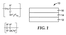
本開示の例示的な複合材料物品が、図1に示される。複合材料物品10は基材12、そして1つの面に、耐磨耗層14及び反射防止層16を含む多層コーティングを備える。反射防止層16は大気に曝露されるように設けられ、耐磨耗層14は、基材12と反射防止層16との間に設けられる。図1では、基材の一方の面にしか多層コーティングが備えられていないが、基材の他方の面にも多層コーティングを備えていてもよい。
An exemplary composite article of the present disclosure is shown in FIG. The
図示されていないが、反射防止層と耐磨耗層以外の層が複合材料物品に組み込まれていてもよく、これには、他の硬コーティング層、接着剤層、プライマー層、光拡散コーティング、回折グレーティング、及び他の微細構造などが含まれるが、その限りではない。反射防止層は耐磨耗層に結合していることが好ましい。 Although not shown, layers other than the antireflective layer and the abrasion resistant layer may be incorporated into the composite article, including other hard coating layers, adhesive layers, primer layers, light diffusion coatings, This includes, but is not limited to, diffraction gratings and other microstructures. The antireflective layer is preferably bonded to the wear resistant layer.
基材
本発明の基材は有機材料基材、すなわち炭素原子を含む基材であってもよいし、無機材料基材であってもよい。例示的な基材として、ポリカーボネート、ポリエチレンテレフタレート(PET)、アクリロニトリルブタジエンスチレン(ABS)、ポリ塩化ビニル(PVC)、酢酸セルロースブチラート(CAB)、ガラス、及びこれらの組み合わせが挙げられる。
Base Material The base material of the present invention may be an organic material base material, that is, a base material containing carbon atoms, or an inorganic material base material. Exemplary substrates include polycarbonate, polyethylene terephthalate (PET), acrylonitrile butadiene styrene (ABS), polyvinyl chloride (PVC), cellulose acetate butyrate (CAB), glass, and combinations thereof.
基材は、平面形状、湾曲形状、又は複雑な湾曲形状であり得る。本発明で開示される構成体は、非平面形状の基材、例えば複数の曲線を有する射出成型された基材に特に有用である。 The substrate can be a planar shape, a curved shape, or a complex curved shape. The constructs disclosed in the present invention are particularly useful for non-planar shaped substrates, such as injection molded substrates having multiple curves.
多層コーティングが設けられ得る基材としては、例えば、プラスチックフィルム、成形プラスチック部品、塗装された及び/又はクリアコートされた自動車のボディパネル、海洋で使用される表面(例えば胴やトリム)、オートバイ部品、タッチスクリーン、光学ディスプレイが挙げられる。 Substrates that can be provided with multilayer coatings include, for example, plastic films, molded plastic parts, painted and / or clear-coated automobile body panels, surfaces used in the ocean (eg torso and trim), motorcycle parts , Touch screen, optical display.
耐磨耗層
耐磨耗層は、高い屈折率の層であり、その屈折率は1.55、1.58又は更に1.60よりも大きい。耐磨耗層の最大屈折率の最大値は、通常1.80以下である。
Wear-resistant layer The wear-resistant layer is a high refractive index layer, whose refractive index is greater than 1.55, 1.58 or even 1.60. The maximum value of the maximum refractive index of the wear resistant layer is usually 1.80 or less.
耐磨耗層はポリマーバインダーを含む。そのようなポリマーバインダーは、単数又は複数のアクリレート架橋システムを有する従来の炭素系ポリマー組成物、ポリウレタン、及びポリアミドを含む。例示的なポリマーバインダーとして、アクリルポリマー、ポリウレタン、ポリイミドが挙げられる。1つの実施形態では、アクリルポリマーは四級アンモニウム基を含む。 The abrasion resistant layer includes a polymer binder. Such polymeric binders include conventional carbon-based polymer compositions, polyurethanes, and polyamides having one or more acrylate crosslinking systems. Exemplary polymer binders include acrylic polymers, polyurethanes, and polyimides. In one embodiment, the acrylic polymer comprises quaternary ammonium groups.
1つの実施形態では、架橋剤を使用してもよい。例示的な架橋剤としては、Nisshinbo Industries,Inc.Japanから商品名「V−04」として入手可能なカルボジイミド架橋剤;Stahl USAより商品名「XR−9174」、CYTEC Surface Specialities,Inc.より商品名「CYMEL 327」として入手可能なメラミン架橋剤が挙げられる。好ましい架橋剤としては、Bayer Materials Scienceから商品名「DESMODUR」(Desmodur L−75及びDesmodur XP2838を含む)で入手可能な脂肪族及び芳香族のポリイソシアネートが挙げられる。架橋剤の混合物もまた有用である。 In one embodiment, a cross-linking agent may be used. Exemplary cross-linking agents include Nishishin Industries, Inc. Carbodiimide crosslinker available from Japan under the trade name “V-04”; trade name “XR-9174” from Stahl USA, CYTEC Surface Specialties, Inc. And a melamine cross-linking agent available under the trade name “CYMEL 327”. Preferred cross-linking agents include aliphatic and aromatic polyisocyanates available from Bayer Materials Science under the trade name “DESMODUR” (including Desmodur L-75 and Desmodur XP2838). Mixtures of crosslinking agents are also useful.
耐磨耗層は、例えば好ましい波長で動作するHバルブや他のランプを用いて紫外線に曝露する方法、対流炉で加熱する方法、又は赤外線に曝露する方法など、従来知られている方法で架橋してもよい。 The wear-resistant layer is crosslinked by a conventionally known method such as a method of exposing to ultraviolet rays using an H bulb or other lamp operating at a preferred wavelength, a method of heating in a convection furnace, or a method of exposing to infrared rays. May be.
1つの実施形態では、耐磨耗層は透明であり、これは可視光(400〜700nm)透過率が少なくとも85%、又は更に90%であることを意味する。 In one embodiment, the abrasion resistant layer is transparent, meaning that the visible light (400-700 nm) transmission is at least 85%, or even 90%.
1つの実施形態では、耐磨耗層は、帯電防止性があり、これは、静電気消失時間が60秒未満であること、又は以下に記述する帯電効率測定法に記された摩擦試験の後の静電気保持が−200V〜+200Vであることを意味する。 In one embodiment, the wear resistant layer is antistatic, which has a static dissipation time of less than 60 seconds, or after a friction test as described in the charging efficiency measurement method described below. It means that the static electricity holding is -200V to + 200V.
好ましい1つの実施形態においては、耐磨耗層の機械的耐久性を無機粒子、特に高屈折率の粒子を導入することによって増強することができる。 In one preferred embodiment, the mechanical durability of the abrasion resistant layer can be enhanced by introducing inorganic particles, particularly high refractive index particles.
様々な高屈折率粒子、例えば、単独又は組み合わせで、ジルコニア(「ZrO2」)、チタニア(「TiO2」)、酸化アンチモン、アルミナ、酸化スズなどが知られている。混合金属酸化物を用いてもよい。高屈折率粒子の屈折率は、少なくとも1.60、1.65、1.70、1.75、1.80、1.85、1.90、1.95、又は2.00である。 Various high refractive index particles, for example, zirconia (“ZrO 2 ”), titania (“TiO 2 ”), antimony oxide, alumina, tin oxide, etc. are known alone or in combination. Mixed metal oxides may be used. The refractive index of the high refractive index particles is at least 1.60, 1.65, 1.70, 1.75, 1.80, 1.85, 1.90, 1.95, or 2.00.
一実施形態では、無機粒子はジルコニアである。耐磨耗層内で用いられるジルコニアは、Nalco Chemical Co.から「Nalco OOSSOO8」という商品名で、及びBuhler AG Uzwil,Switzerlandから「BYHLER ZIRCONIA Z−WO SOL」という商品名で入手可能である。ジルコニアナノ粒子はまた、米国特許第7,241,437号及び同第6,376,590号に記載されているように調製されてもよい。 In one embodiment, the inorganic particles are zirconia. Zirconia used in the wear resistant layer is available from Nalco Chemical Co. Under the trade name “Nalco OOSSOOO8” and from Buhler AG Uzwil, Switzerland under the trade name “BYHLER ZIRCONIA Z-WO SOL”. Zirconia nanoparticles may also be prepared as described in US Pat. Nos. 7,241,437 and 6,376,590.
一実施形態において、無機粒子の表面は、改質されている。粒子の表面を、ポリマーバインダーに対する反応性官能基を有する、アルキル基又はフッ素化アルキル基及びそれらの混合物を有するように企図されたポリマーコーティングで改質してもよい。そのような官能基としては、メルカプタン、ビニル、アクリレート及び、特にクロロ、ブロモ、イオド又はアルコキシシランの硬化サイトモノマーを含むポリマーバインダーと無機粒子の相互作用を増大すると考えられている他のものを含む。本発明によって想到されている表面改質剤の具体的なものとして、3−メタクリルオキシプロピルトリメトキシシラン(A174,OSI Specialties Chemical)、トリメトキシ及びトリエトキシシラン、並びにヘキサメチルジシランなどのビニルトリアルコキシシラン(Aldrich Coから入手可能)が挙げられるが、この限りではない。 In one embodiment, the surface of the inorganic particles is modified. The surface of the particles may be modified with a polymer coating intended to have alkyl groups or fluorinated alkyl groups and mixtures thereof having reactive functional groups for the polymer binder. Such functional groups include mercaptans, vinyls, acrylates, and others that are believed to increase the interaction of inorganic particles with polymer binders, particularly including cure site monomers of chloro, bromo, iodo or alkoxysilanes. . Specific examples of surface modifiers envisioned by the present invention include 3-methacryloxypropyltrimethoxysilane (A174, OSI Specialties Chemical), trimethoxy and triethoxysilane, and vinyltrialkoxysilanes such as hexamethyldisilane. (Available from Aldrich Co), but is not limited to this.
表面改質剤の混合物が有用であり、その場合、表面改質剤の少なくとも1つには、硬化性樹脂と共重合可能な官能基が含まれている。表面改質剤の混合物によって、より低い粘度を得ることができる。例えば、重合化基は、エチレン不飽和であるか、又は開環重合を起こす環式官能基であり得る。エチレン不飽和重合化基は、例えば、アクリレート基若しくはメタクリレート基、又はビニル基であり得る。開環重合を受ける環式官能基は、一般的に、酸素、イオウ又は窒素のようなヘテロ原子を含有し、好ましくはエポキシドのように酸素を含有する3員環である。 Mixtures of surface modifiers are useful, in which case at least one of the surface modifiers contains a functional group copolymerizable with the curable resin. Lower viscosities can be obtained with a mixture of surface modifiers. For example, the polymerizing group can be an ethylenically unsaturated or cyclic functional group that undergoes ring opening polymerization. The ethylenically unsaturated polymerizing group can be, for example, an acrylate group or a methacrylate group, or a vinyl group. The cyclic functional group undergoing ring-opening polymerization generally contains a heteroatom such as oxygen, sulfur or nitrogen, and is preferably a three-membered ring containing oxygen such as epoxide.
粒子の表面改質は、様々な既知の方法、例えば米国特許第7,241,437号及び米国特許第6,376,590号に記載されている方法で実現させることができる。同出願は参照により本明細書に援用される。 The surface modification of the particles can be accomplished by various known methods, such as those described in US Pat. No. 7,241,437 and US Pat. No. 6,376,590. This application is incorporated herein by reference.
無機粒子には、実質的に単分散の粒径分布、又は実質的に単分散の分布の2つ以上を混ぜ合わせることによって得られるポリモーダル分布を持たせるのが好ましい。あるいは、無機粒子は、粒子を所望の粒径範囲に粉砕することによって得られる様々な粒径を持たせるように組み込むことができる。無機酸化物粒子は、凝集によって無機酸化物粒子の光学散乱(ヘイズ)若しくは沈殿又はゲル化が生じる可能性があるため、典型的には非凝集体(実質的に分離体)である。無機酸化物粒子は典型的にはコロイドの大きさであり、5ナノメートル〜100ナノメートルの平均粒子直径を有する。十分な透明度を有するように、表面改質無機粒子の粒径は約50nm未満であるのが好ましい。無機酸化物粒子の平均粒径は、透過型電子顕微鏡を使用して、所与の直径の無機酸化物粒子を計数して測定できる。透明性の観点から、モノモーダルな粒子分布が好ましい。 The inorganic particles preferably have a substantially monodispersed particle size distribution or a polymodal distribution obtained by mixing two or more of the substantially monodispersed distributions. Alternatively, the inorganic particles can be incorporated to have various particle sizes obtained by grinding the particles to a desired particle size range. Inorganic oxide particles are typically non-aggregated (substantially separated) because aggregation can cause optical scattering (haze) or precipitation or gelation of the inorganic oxide particles. Inorganic oxide particles are typically colloidal in size and have an average particle diameter of 5 nanometers to 100 nanometers. The surface modified inorganic particles preferably have a particle size of less than about 50 nm so as to have sufficient transparency. The average particle diameter of the inorganic oxide particles can be measured by counting inorganic oxide particles having a given diameter using a transmission electron microscope. From the viewpoint of transparency, a monomodal particle distribution is preferable.
無機ナノ粒子の濃度は、典型的には、乾燥コーティングの固形で80重量%以下である。いくつかの実施形態では、耐磨耗層中に固体で35〜70重量%の無機ナノ粒子が含まれるのが好ましい。 The concentration of inorganic nanoparticles is typically no more than 80% by weight of the dry coating solids. In some embodiments, it is preferred that the wear resistant layer includes 35 to 70 wt% inorganic nanoparticles that are solid.
1つの実施形態では、耐磨耗層の厚みが全構成体の10%未満、1%未満、又は更には0.5%未満である。1つの実施形態では、典型的には耐磨耗層の厚みは少なくとも0.5マイクロメートル、1マイクロメートル、又は更には2マイクロメートルであり、典型的には10マイクロメートル以下である。 In one embodiment, the wear-resistant layer has a thickness of less than 10%, less than 1%, or even less than 0.5% of the total construction. In one embodiment, the wear-resistant layer typically has a thickness of at least 0.5 micrometers, 1 micrometer, or even 2 micrometers, typically no more than 10 micrometers.
反射防止層
反射防止層は、低屈折率の層であり、その屈折率は1.48未満、1.46未満、1.44未満又は更に1.40未満である。反射防止層の最小屈折率は一般には少なくとも約1.35である。耐磨耗層と反射防止層との屈折率の差は、一般的には少なくとも0.05、更には0.1である。
Antireflective layer The antireflective layer is a low refractive index layer with a refractive index of less than 1.48, less than 1.46, less than 1.44 or even less than 1.40. The minimum refractive index of the antireflective layer is generally at least about 1.35. The difference in refractive index between the wear resistant layer and the antireflective layer is generally at least 0.05, and even 0.1.
反射防止層はフルオロシランポリマーを含み、このフルオロシランポリマーは、少なくとも1つの2価のモノマー単位A及び少なくとも1つの2価のモノマー単位Bを含む。 The antireflective layer comprises a fluorosilane polymer, the fluorosilane polymer comprising at least one divalent monomer unit A and at least one divalent monomer unit B.
モノマー単位Aは、式 Monomer unit A has the formula
で表され、式中、R1は、H又はメチルを表す。
In the formula, R 1 represents H or methyl.
L1は、共有結合(すなわち、炭素とケイ素原子との間の共有結合)、又は1〜10個の炭素原子を有する2価の脂肪族基を表す。好適な2価の脂肪族基の例として、2価のアルキレン基(例えば、メチレン、エチレン、1,2−プロピレン、1,3−プロピレン、1,4−ブチレン、1,6−へキシレン、1,8−オクチレン、1,9−ノニレン及び1,10−デシレン)、及び−C(=O)O(CH2)v−(式中、vは2、3、4、又は5)、−及びO(CH2)p−(式中、pは2、3、4、5又は6)が挙げられる。いくつかの実施形態においては、L1は、共有結合であるのが好ましい。 L 1 represents a covalent bond (that is, a covalent bond between a carbon and a silicon atom) or a divalent aliphatic group having 1 to 10 carbon atoms. Examples of suitable divalent aliphatic groups include divalent alkylene groups such as methylene, ethylene, 1,2-propylene, 1,3-propylene, 1,4-butylene, 1,6-hexylene, , 8-octylene, 1,9-nonylene and 1,10-decylene), and —C (═O) O (CH 2 ) v — (where v is 2, 3, 4, or 5), — and O (CH 2 ) p — (wherein p is 2, 3, 4, 5 or 6). In some embodiments, L 1 is preferably a covalent bond.
各Y1は独立して、1〜6個の炭素原子を有するヒドロカルビル基、1〜6個の炭素原子を有するヒドロカルビル基(概して非加水分解性である)を表す。Y1の例としては、メチル、エチル、プロピル、イソブチル、ペンチル、シクロヘキシル、及びフェニルが挙げられる。 Each Y 1 independently represents a hydrocarbyl group having 1 to 6 carbon atoms, a hydrocarbyl group having 1 to 6 carbon atoms (generally non-hydrolyzable). Examples of Y 1 include methyl, ethyl, propyl, isobutyl, pentyl, cyclohexyl, and phenyl.
各Y2は独立して、加水分解性基を表す。本発明との関連における「加水分解性基」という用語は、典型的な縮合反応条件下で直接縮合反応できるか、又は典型的な縮合反応条件で加水分解でき、それにより、縮合反応できる化合物をもたらす基を指す。加水分解性基の例としては、ハロ基(例えば、クロロ、ブロモ、ヨード)、アルコキシ基(例えば、1〜4個の炭素原子、好ましくは1又は2個の炭素原子を有するアルコキシ基)、アリールオキシ基(例えばフェノキシ基)、ヒドロキシル基、及び2〜4個の炭素原子を有するアルカノイルオキシ基(例えば、アセトキシ、プロパノイルオキシ、ブタノイルオキシ)が挙げられる。典型的な縮合反応条件には、酸性条件又は塩基性条件が含まれる。 Each Y 2 independently represents a hydrolyzable group. The term “hydrolyzable group” in the context of the present invention refers to a compound that can be condensed directly under typical condensation reaction conditions or hydrolyzed under typical condensation reaction conditions, thereby allowing the condensation reaction to occur. Refers to the resulting group. Examples of hydrolyzable groups include halo groups (eg chloro, bromo, iodo), alkoxy groups (eg alkoxy groups having 1 to 4 carbon atoms, preferably 1 or 2 carbon atoms), aryl Examples include an oxy group (for example, phenoxy group), a hydroxyl group, and an alkanoyloxy group having 2 to 4 carbon atoms (for example, acetoxy, propanoyloxy, butanoyloxy). Typical condensation reaction conditions include acidic conditions or basic conditions.
gは、0、1、又は2であり、好ましくは0である。 g is 0, 1, or 2, preferably 0.
そのようなモノマー単位はエチレン性不飽和加水分解性シランなどのモノマーから誘導されてもよく、それらを作製する方法は、国際公開第98/28307 A1号(Ceskaら)に記載されている。モノマー単位はまた、フリーラジカル的に重合可能な加水分解性シランなどの市販されているモノマーから誘導されてもよい。このフリーラジカル的に重合可能な加水分解性シランとしては、アリルトリクロロシラン、アリルトリエトキシシラン、アリルトリメトキシシラン、ビニルトリ−t−ブトキシシラン、ビニルトリアセトキシシラン、ビニルトリクロロシラン、ビニルトリエトキシシラン、ビニルトリイソプロペノキシシラン、ビニルトリイソプロポキシシラン、ビニルトリメトキシシラン、ビニルトリフェノキシシラン、ビニルトリス(1−メトキシ−2−プロポキシ)シラン、及びビニル(2−メトキシエトキシ)シランなどが含まれ、これらはすべてGelest,Inc.,Morrisville,Pennsylvaniaより入手可能である。その他の好適なモノマーとしては、ビニルジメチルメトキシシラン、ビニルジメチルエトキシシラン、ビニルメチルジメトキシシラン、ビニルメチルジエトキシシラン、ビニルエチルジエトキシシランが挙げられる。 Such monomer units may be derived from monomers such as ethylenically unsaturated hydrolyzable silanes and methods for making them are described in WO 98/28307 A1 (Ceska et al.). Monomer units may also be derived from commercially available monomers such as free radically polymerizable hydrolyzable silanes. This free radically polymerizable hydrolyzable silane includes allyltrichlorosilane, allyltriethoxysilane, allyltrimethoxysilane, vinyltri-t-butoxysilane, vinyltriacetoxysilane, vinyltrichlorosilane, vinyltriethoxysilane, Includes vinyl triisopropenoxy silane, vinyl triisopropoxy silane, vinyl trimethoxy silane, vinyl triphenoxy silane, vinyl tris (1-methoxy-2-propoxy) silane, vinyl (2-methoxyethoxy) silane, etc. Are all in Gelest, Inc. , Morrisville, Pennsylvania. Other suitable monomers include vinyldimethylmethoxysilane, vinyldimethylethoxysilane, vinylmethyldimethoxysilane, vinylmethyldiethoxysilane, and vinylethyldiethoxysilane.
また、好適なモノマー単位は、アルコキシシランとアセチレンの触媒を介在したヒドロシリル化反応によって調製される、ビニルアルコキシシランより誘導してもよい。別のアプローチは、ビニルクロロシランをアルコールと反応させることを含む。調製の方法は、米国特許第2,637,738号(Wagner)、同第4,579,965号(Kennerら)及び同第5,041,595号(Yangら)に記載されている。ビニルアルコキシシランもまた、例えばSigma−Aldrich Co.及びGelest Inc.から市販されている。 Suitable monomer units may also be derived from vinyl alkoxysilanes prepared by hydrosilylation reactions mediated by alkoxysilane and acetylene catalysts. Another approach involves reacting vinyl chlorosilane with an alcohol. Methods of preparation are described in US Pat. Nos. 2,637,738 (Wagner), 4,579,965 (Kenner et al.) And 5,041,595 (Yang et al.). Vinyl alkoxysilanes are also described, for example, by Sigma-Aldrich Co. And Gelest Inc. Commercially available.
モノマー単位Bは、式 Monomer unit B has the formula
で表される。R2、R3、及びR4はH、メチル、トリフルオロメチル、又はFを表し、ここでR2、R3、及びR4の少なくとも1つはFである。いくつかの実施形態では、R2、R3、及びR4の少なくとも2つはFである。いくつかの実施形態ではR2及びR3はFであり、R4はトリフルオロメチルである。 It is represented by R 2 , R 3 , and R 4 represent H, methyl, trifluoromethyl, or F, wherein at least one of R 2 , R 3 , and R 4 is F. In some embodiments, at least two of R 2 , R 3 , and R 4 are F. In some embodiments, R 2 and R 3 are F and R 4 is trifluoromethyl.
Rf 1は、共有結合又は−(CF2O)a−、−(CF2CF2O)b−、−(CF2CF2CF2O)c−、−(CF2CF2CF2CF2O)d−、−(CF2CF(CF3)O)e−、及びこれらの組み合わせからなる群から選択される2価の基を表し、式中、a、b、c、d、及びeは、0〜130の範囲の整数を表す。 R f 1 is a covalent bond or — (CF 2 O) a —, — (CF 2 CF 2 O) b —, — (CF 2 CF 2 CF 2 O) c —, — (CF 2 CF 2 CF 2 CF 2 O) d -,-(CF 2 CF (CF 3 ) O) e- , and a divalent group selected from the group consisting of these, wherein a, b, c, d, and e represents an integer ranging from 0 to 130.
いくつかの実施形態においては、1≦a+b+c+d+e≦130である。いくつかの実施形態においては、2≦a+b+c+d+e≦130である。いくつかの実施形態においては、a、b、c、d、又はeのうちの少なくとも1つは、1又は2〜130、好ましくは1又は2〜80、より好ましくは1又は2〜50、より好ましくは1又は2〜40の範囲の整数を表す。いくつかの実施形態においては、a、b、c、d、又はeのうちの少なくとも1つは、1又は2〜10、好ましくは1又は2〜5の範囲の整数を表す。いくつかの実施形態においては、1≦a+b+c+d+e≦50である。いくつかの実施形態においては、2≦a+b+c+d+e≦50である。いくつかの実施形態においては、10≦a+b+c+d+e≦130である。いくつかの実施形態においては、10≦a+b+c+d+e≦50である。いくつかの実施形態においては、30≦a+b+c+d+e≦60である。いくつかの実施形態においては、4≦a+b+c+d+e≦130、好ましくは4≦a+b+c+d+e≦80、より好ましくは4≦a+b+c+d+e≦50、より好ましくは4≦a+b+c+d+e≦40、更に好ましくは4≦a+b+c+d+e≦40である。 In some embodiments, 1 ≦ a + b + c + d + e ≦ 130. In some embodiments, 2 ≦ a + b + c + d + e ≦ 130. In some embodiments, at least one of a, b, c, d, or e is 1 or 2-130, preferably 1 or 2-80, more preferably 1 or 2-50, and more. Preferably it represents an integer in the range of 1 or 2-40. In some embodiments, at least one of a, b, c, d, or e represents an integer in the range of 1 or 2-10, preferably 1 or 2-5. In some embodiments, 1 ≦ a + b + c + d + e ≦ 50. In some embodiments, 2 ≦ a + b + c + d + e ≦ 50. In some embodiments, 10 ≦ a + b + c + d + e ≦ 130. In some embodiments, 10 ≦ a + b + c + d + e ≦ 50. In some embodiments, 30 ≦ a + b + c + d + e ≦ 60. In some embodiments, 4 ≦ a + b + c + d + e ≦ 130, preferably 4 ≦ a + b + c + d + e ≦ 80, more preferably 4 ≦ a + b + c + d + e ≦ 50, more preferably 4 ≦ a + b + c + d + e ≦ 40, more preferably 4 ≦ a + b + c + d + e ≦ 40. .
Rf 1のいくつかの例として、−(CF2O)20〜30−、−(CF2CF2O)30〜40−、
−(CF2CF2CF2O)40〜50−、−(CF2CF2CF2CF2O)20〜30−、−(CF2CF(CF3)O)4〜8−、
−(CF2CF(CF3)O)30〜40−、−(CF2CF2O)30〜40(CF2CF(CF3)O)30〜40−、及び
−(CF2O)20〜30(CF2CF2O)85〜100−が挙げられる。組み合わせとして存在している場合には、単位−(CF2O)−、
−(CF2CF2O)−、−(CF2CF2CF2O)−、−(CF2CF2CF2CF2O)−、及び−(CF2CF(CF3)O)−は、ランダム又は擬似ランダムな順序で、及び/又はブロック内で存在していてもよい。
Some examples of R f 1 include — (CF 2 O) 20-30 −, — (CF 2 CF 2 O) 30-40 −,
- (CF 2 CF 2 CF 2 O) 40~50 -, - (CF 2 CF 2 CF 2 CF 2 O) 20~30 -, - (CF 2 CF (CF 3) O) 4~8 -,
- (CF 2 CF (CF 3 ) O) 30~40 -, - (CF 2 CF 2 O) 30~40 (CF 2 CF (CF 3) O) 30~40 -, and - (CF 2 O) 20 ~30 (CF 2 CF 2 O) 85~100 - and the like. When present as a combination, the unit — (CF 2 O) —,
- (CF 2 CF 2 O) -, - (CF 2 CF 2 CF 2 O) -, - (CF 2 CF 2 CF 2 CF 2 O) -, and - (CF 2 CF (CF 3 ) O) - is May be present in a random or pseudo-random order and / or within a block.
Rf 2は、ペルフルオロアルキル基である。Rf 2は、1〜6個の炭素原子を有するのが好ましい。好適なペルフルオロアルキル基の例としては、トリフルオロメチル、ペンタフルオロエチル、ノナフルオロブチル、ノナフルオロイソブチル、ペルフルオロペンチル、及びペルフルオロヘキシルが挙げられる。 R f 2 is a perfluoroalkyl group. R f 2 preferably has 1 to 6 carbon atoms. Examples of suitable perfluoroalkyl groups include trifluoromethyl, pentafluoroethyl, nonafluorobutyl, nonafluoroisobutyl, perfluoropentyl, and perfluorohexyl.
モノマー単位Bのモノマー単位として好適なものは、フッ素化ビニルエーテルから誘導されたものが、例えば、当該技術分野で従来よく知られた方法、例えば、米国特許番号第6,255,536 B1号(Wormら)に記載されていように調製できる。 Suitable monomer units for monomer unit B are those derived from fluorinated vinyl ethers, for example, methods well known in the art, such as US Pat. No. 6,255,536 B1 (Worm). Et al.).
いくつかの実施形態においては、単一又は複数のモノマー単位Aの単一又は複数のモノマー単位Bに対する平均モル比は、少なくとも1(例えば少なくとも10、少なくとも40、少なくとも80、少なくとも100、少なくとも125、又更には少なくとも150)である。いくつかの実施形態においては、単一又は複数のモノマー単位Bの単一又は複数のモノマー単位Aに対する重量比は、少なくとも0.8(例えば少なくとも5、少なくとも10、少なくとも20、少なくとも25、又更には少なくとも30)である。 In some embodiments, the average molar ratio of single or multiple monomer units A to single or multiple monomer units B is at least 1 (eg, at least 10, at least 40, at least 80, at least 100, at least 125, Still further, at least 150). In some embodiments, the weight ratio of single or multiple monomer units B to single or multiple monomer units A is at least 0.8 (eg, at least 5, at least 10, at least 20, at least 25, or even Is at least 30).
1つの実施形態では、フルオロシランポリマーは、式 In one embodiment, the fluorosilane polymer has the formula
(式中、R5はH又はメチルを表し、pは正の整数である)で表されるp個のモノマー単位Cを更に含む。
(Wherein R 5 represents H or methyl, and p is a positive integer), and further includes p monomer units C.
このようなモノマー単位Cが存在する場合、モノマー単位Cは、その個々の量又は組み合わせた量が、存在するモノマーの総重量に対して、好ましくは20重量パーセント未満、より好ましくは10重量パーセント未満、より好ましくは2重量パーセント未満で存在する。 When such monomer units C are present, the monomer units C are preferably less than 20 weight percent, more preferably less than 10 weight percent, in individual or combined amounts, based on the total weight of monomers present. More preferably less than 2 weight percent.
モノマー単位Cは、米国特許第4,737,559号(Kellenら)に記載されているもの等、光架橋可能な基を含む光架橋性基を含むフリーラジカル重合性モノマーから誘導されてもよい。具体例としては、p−アクリルオキシベンゾフェノン、p−アクリルオキシエトキシベンゾフェノン、p−N−(メチルアクリルオキシエチル)カルバモイルエトキシベンゾフェノン、p−アクリルオキシアセトフェノン、o−アクリルアミドアセトフェノン、及びアクリル化アントラキノンが挙げられる。 Monomer unit C may be derived from a free radical polymerizable monomer containing a photocrosslinkable group containing a photocrosslinkable group, such as those described in US Pat. No. 4,737,559 (Kellen et al.). . Specific examples include p-acryloxybenzophenone, p-acryloxyethoxybenzophenone, pN- (methylacryloxyethyl) carbamoylethoxybenzophenone, p-acryloxyacetophenone, o-acrylamide acetophenone, and acrylated anthraquinone. .
いくつかの実施形態においては、モノマー単位Cは、4〜22個の炭素原子を有するアルキル(メタ)アクリレート(例えばブチルアクリレート、イソボルニルアクリレート)、4〜22個の炭素原子を有するアルコキシアルキルメタクリレート、6〜22個の炭素原子を有するエポキシアクリレート(例えばグリシジルメタクリレート)、6〜22個の炭素原子を有するイソシアナートアルキル(メタ)アクリレート(例えば3−イソシアナートプロピル(メタ)アクリレート))、及びこれらの組み合わせのモノマーから誘導されてもよい。 In some embodiments, the monomer unit C is an alkyl (meth) acrylate having 4 to 22 carbon atoms (eg, butyl acrylate, isobornyl acrylate), an alkoxyalkyl methacrylate having 4 to 22 carbon atoms. Epoxy acrylates having 6 to 22 carbon atoms (eg glycidyl methacrylate), isocyanate alkyl (meth) acrylates having 6 to 22 carbon atoms (eg 3-isocyanatopropyl (meth) acrylate)), and these May be derived from a combination of monomers.
このモノマー単位Cを生成するのに使用される追加のモノマーは、架橋を引き起こす複数のフリーラジカル重合性基を含まないのが好ましいが、例えば、シロップをもたらすごく少量の架橋は許容可能である。 The additional monomer used to produce this monomer unit C preferably does not contain a plurality of free radical polymerizable groups that cause crosslinking, but, for example, very small amounts of crosslinking resulting in syrup are acceptable.
いくつかの実施形態においては、フルオロシランポリマー中のフリーラジカル重合性モノマーをすべて合わせた合計は、フッ素化アルケンの0.49重量パーセント以下(好ましくは0.3重量パーセント未満、より好ましくは0.1重量パーセント未満)である。いくつかの実施形態においては、フルオロシランポリマーに使用されるフリーラジカル重合性モノマーをすべて合わせたものは全体として、フッ素化アルケンを含まない。 In some embodiments, the sum of all free radical polymerizable monomers in the fluorosilane polymer is 0.49 weight percent or less (preferably less than 0.3 weight percent, more preferably less than 0.3 weight percent) of the fluorinated alkene. Less than 1 weight percent). In some embodiments, the combined free radical polymerizable monomers used in the fluorosilane polymer as a whole do not include fluorinated alkenes.
フルオロシランポリマーの数平均及び/又は重量平均分子量は典型的には、少なくとも10000g/モル、少なくとも20000g/モル、少なくとも50000g/モル、少なくとも150000g/モル、及び/又は更には少なくとも200000g/モルであるが、これは必須要件ではない。高い分子量を得るために、重合は、連鎖移動剤(例えばメルカプタン)を加えずに行うのが好ましい。 The number average and / or weight average molecular weight of the fluorosilane polymer is typically at least 10,000 g / mol, at least 20000 g / mol, at least 50000 g / mol, at least 150,000 g / mol, and / or even at least 200000 g / mol. This is not a requirement. In order to obtain a high molecular weight, the polymerization is preferably carried out without the addition of a chain transfer agent (eg mercaptan).
かかる組成物は米国特許出願公開第61/839122号(2013年6月25日出願)に開示されており、その開示は本明細書に参照により組み込まれる。 Such compositions are disclosed in U.S. Patent Application Publication No. 61/839122 (filed June 25, 2013), the disclosure of which is hereby incorporated by reference.
1つの実施形態では、反射防止層は透明であり、これは可視光(400〜700nm)透過率が少なくとも85%、又は90%でさえあることを意味する。 In one embodiment, the antireflective layer is transparent, meaning that the visible light (400-700 nm) transmission is at least 85%, or even 90%.
1つの実施形態では、反射防止層は、関心のある波長のおよそ4分の1波長の光学的厚みを有する。このような厚みは典型的には1マイクロメートル未満、より典型的には約0.5マイクロメートル未満であり、約90nm〜200nmである場合が多い。例えば、1つの実施形態では、反射防止層は可視光の波長(400〜700nm)又はその倍数の約4分の1の光学厚みを有する。そのような厚みとは、典型的には約90nm〜180nmであり、125nm前後が好ましい。1つの実施形態では、反射防止層は、赤外線の波長(700nm〜1mm)又はその倍数の約4分の1の光学厚みを有し、例えば、そのような厚みは約170〜500nmである。 In one embodiment, the antireflective layer has an optical thickness of approximately a quarter wavelength of the wavelength of interest. Such thickness is typically less than 1 micrometer, more typically less than about 0.5 micrometers, and often is between about 90 nm and 200 nm. For example, in one embodiment, the antireflective layer has an optical thickness of about one quarter of the wavelength of visible light (400-700 nm) or multiples thereof. Such thickness is typically about 90 nm to 180 nm, preferably around 125 nm. In one embodiment, the antireflective layer has an optical thickness of about one quarter of the infrared wavelength (700 nm to 1 mm) or multiples thereof, for example, such thickness is about 170 to 500 nm.
反射防止層の屈折率及び反射防止層の厚みに加え、反射防止層の表面粗さも得られるコーティングされた物品の光反射特性に影響を与える。より高い反射防止性能のためには、空間周波数がより高い表面粗さを有するほうが好ましい。低周波粗さは、光を散乱し、反射を低減しない。完全に滑らかな表面はFresnel式に従って光を反射する。高空間周波数の粗さを加えることは、反射防止性能を付与する可能性がある。1つの実施形態においては、反射防止層はナノ構造であり、すなわち粗い表面を有している。 In addition to the refractive index of the antireflective layer and the thickness of the antireflective layer, the surface roughness of the antireflective layer also affects the light reflective properties of the resulting coated article. For higher antireflection performance, it is preferable that the spatial frequency has a higher surface roughness. Low frequency roughness scatters light and does not reduce reflection. A perfectly smooth surface reflects light according to the Fresnel equation. Adding high spatial frequency roughness may impart antireflection performance. In one embodiment, the antireflective layer is nanostructured, i.e. has a rough surface.
表面粗さは表面の粗さの尺度である。表面粗さは、ナノメートルの範囲(例えば、少なくとも1〜100nm、又は更には5〜50nm)の形状を解像できる原子間力顕微鏡(AFM)などの方法を用いて測定する。表面粗さを表す場合には、平均粗さ(Ra)又はRMS粗さ(Rq)が使用可能である。Image Rqはイメージデータ平均面からの高さの偏差の二乗平均平方根であり、 Surface roughness is a measure of surface roughness. The surface roughness is measured using a method such as an atomic force microscope (AFM) that can resolve shapes in the nanometer range (eg, at least 1-100 nm, or even 5-50 nm). When expressing surface roughness, average roughness (Ra) or RMS roughness (Rq) can be used. Image Rq is the root mean square of the deviation in height from the image data average plane,
(式中、Nは点の総数、Zはそれぞれの点における高さ(平均高さに対する相対値)である)で表される。
(Where N is the total number of points, and Z is the height at each point (relative value to the average height)).
Image Raは平均面から測定した表面高さ偏差の絶対値の算術平均であり、 Image Ra is the arithmetic average of the absolute value of the surface height deviation measured from the average surface,
(式中、Nは点の総数、Zはそれぞれの点における高さ(平均高さに対する相対値)である)で表される。
(Where N is the total number of points, and Z is the height at each point (relative value to the average height)).
生データのフーリエ分析によって、粗さを異なる形状サイズや空間周波数で検証することができる。高空間周波数フィルターを使用してナノスケールの形状の粗さへの寄与を判定することができる。あるいは、ローパス空間周波数フィルターを用いて、光を反射しやすい大きい形状(例えば、ミクロスケール以上の形状)からの粗さへの寄与を判定することも可能である。ローパス空間周波数フィルターを使用する際に、ローパスフィルターと共にハイパス空間周波数フィルターを使用してサンプル表面のうねり(waviness)を取り除いてもよい(すなわち、バンドパスフィルター)。矩形フーリエフィルターウィンドウを使用してもよいが、リンギングアーティファクトがフィルタリング後のデータに観察された場合には、当該技術分野で従来知られているように、ガウシアン・フーリエフィルターウィンドウを代わりに使用してもよい。例えば、ASME standard B46.1−2009:「Surface Texture:Surface Roughness,Waviness,and Lay」を参照のこと。当該技術分野において通常の技術を有する者であれば理解されることであるが、表面粗さの測定は、意味のある測定とするためには、サンプルにおいてデブリや欠陥(例えば、意図していない泡、凹み、擦り傷等)がない領域で実施する必要がある。Bruker Corp.,Santa Barbara,CAより入手可能な、商品名「VISION」等のソフトウェアプログラムを使用してもよい。また、MathWorks,Natick,MAより入手可能な商品名「MATLAB」等のデータ処理ソフトウェアを使用してもよい。 Roughness can be verified at different shape sizes and spatial frequencies by Fourier analysis of the raw data. A high spatial frequency filter can be used to determine the contribution of the nanoscale shape to roughness. Alternatively, it is also possible to determine the contribution to roughness from a large shape that easily reflects light (for example, a shape larger than a microscale) using a low-pass spatial frequency filter. When using a low-pass spatial frequency filter, the sample surface waviness may be removed using a high-pass spatial frequency filter along with the low-pass filter (ie, a band-pass filter). A rectangular Fourier filter window may be used, but if ringing artifacts are observed in the filtered data, use a Gaussian Fourier filter window instead, as is conventionally known in the art. Also good. See, for example, ASME standard B46.1-2009: “Surface Texture: Surface Roughness, Wineness, and Ray”. As will be appreciated by those having ordinary skill in the art, the measurement of surface roughness should be debris and defects (eg unintentional) in the sample in order to make a meaningful measurement. It is necessary to carry out in an area free from bubbles, dents, scratches and the like. Bruker Corp. Software programs such as “VISION”, trade name available from Santa Barbara, Calif. May be used. Alternatively, data processing software such as “MATLAB”, a trade name available from MathWorks, Natick, MA may be used.
高空間周波数のフィルターとしては、好ましい光(例えば、可視光)の空間周波数よりも大きいが、サンプリングされたデータの解像限界限よりも低い周波数を選択するのがよい。1つの実施形態では、高空間周波数フィルターが5000mm−1であるとき、反射防止層のRq値は、0.4、0.5、1、2、4又は更に6nm超である。1つの実施形態では、高空間周波数フィルターが10000mm−1であるとき、反射防止層のRq値は、0.3、0.4、0.5、1、2又は更に2.5nm超である。 As the high spatial frequency filter, it is preferable to select a frequency that is higher than the spatial frequency of preferable light (for example, visible light) but lower than the resolution limit of the sampled data. In one embodiment, when the high spatial frequency filter is 5000 mm −1 , the Rq value of the antireflection layer is 0.4, 0.5, 1 , 2, 4, or even greater than 6 nm. In one embodiment, when the high spatial frequency filter is 10000 mm −1 , the Rq value of the antireflection layer is 0.3, 0.4, 0.5, 1, 2 or even greater than 2.5 nm.
1つの実施形態では、低空間周波数バンドパスフィルターが200mm−1〜2000mm−1であるとき、反射防止層のRq値は、30、25、20、15、10、7又は更に5nm未満である。 In one embodiment, when the low spatial frequency band-pass filter is 200mm -1 ~2000mm -1, Rq value of the antireflection layer is less than 30,25,20,15,10,7 or even 5 nm.
1つの実施形態において、反射防止層は更にシリカナノ粒子を含む。 In one embodiment, the antireflective layer further comprises silica nanoparticles.
シリカナノ粒子は、使用された無機ナノ粒子に依存して、少なくとも25nm、20nm、15nm、10nm、5nm、又は更には3nmの一次粒子の平均直径を有し、最大で約200nm、100nm、50nm、30nm、20nm、又は更に10nmの一次粒子の平均直径を有する。反射防止層で用いられる無機ナノ粒子は、典型的に、凝集していない。無機ナノ粒子が一次粒子の凝集体である場合、凝集ナノ粒子の最大断面寸法は、約3nm〜約100nm、約3nm〜約50nm、約3nm〜約20nm、又は更には約3nm〜約10nmの範囲内である。 Silica nanoparticles have an average primary particle diameter of at least 25 nm, 20 nm, 15 nm, 10 nm, 5 nm, or even 3 nm, depending on the inorganic nanoparticles used, up to about 200 nm, 100 nm, 50 nm, 30 nm. , 20 nm, or even 10 nm. Inorganic nanoparticles used in the antireflective layer are typically not agglomerated. When the inorganic nanoparticles are aggregates of primary particles, the maximum cross-sectional dimensions of the aggregated nanoparticles range from about 3 nm to about 100 nm, from about 3 nm to about 50 nm, from about 3 nm to about 20 nm, or even from about 3 nm to about 10 nm. Is within.
反射防止層の無機ナノ粒子は、ヒュームドシリカ、発熱性シリカ、沈殿シリカ等の材料とは区別することができる。このようなシリカ材料は、高剪断混合の非存在下において凝集体の形態で本質的に不可逆的に互いに結合している一次粒子で構成されていることが当業者には公知である。これらシリカ材料は、100nm超(例えば、典型的に少なくとも200ナノメートル)の平均粒径を有し、これらから個々の一次粒子を直接抽出することは不可能である。 The inorganic nanoparticles of the antireflection layer can be distinguished from materials such as fumed silica, exothermic silica, and precipitated silica. It is known to those skilled in the art that such silica materials are composed of primary particles that are essentially irreversibly bound together in the form of aggregates in the absence of high shear mixing. These silica materials have an average particle size greater than 100 nm (eg, typically at least 200 nanometers), from which it is impossible to extract individual primary particles directly.
これらの無機ナノ粒子は、コロイド状分散液の形態であってよい。有用な市販の非修飾シリカナノ粒子の例としては、商品名「NALCO COLLOIDAL SILICAS」としてNalco Chemical Co.(Naperville,IL)から入手可能な市販のコロイド状シリカゾルが挙げられる。例えば、このようなシリカとしては、NALCOの製品1040、1042、1050、1060、2327及び2329が挙げられる。使用可能な市販のシリカナノ粒子の他の例として、Nissan Chemicals(Houston,TX)より入手可能な商品名「ORGANOSILICASOL」(例えば「ORGANOSILICASOL IPA−ST」及び「ORGANOSILICASOL IPA−ST−L」)で販売されているものが挙げられる。1つの実施形態では、無機ナノ粒子は異方性ナノ粒子(例えば、細長いナノ粒子)を含む。細長いシリカナノ粒子の例として、Nissan Chemicals(Houston,TX)より入手可能な商品名「ORGANOSILICASOL」(例えば「ORGANOSILICASOL IPA−ST−UP」)で販売されているものが挙げられる。無機ナノ粒子は、上記の化学反応を用いて表面改質されていてもよいし、されていなくてもよい。 These inorganic nanoparticles may be in the form of a colloidal dispersion. Examples of useful commercially available unmodified silica nanoparticles include Nalco Chemical Co. under the trade name “NALCO COLORIDAL SILICAS”. Commercially available colloidal silica sols available from (Naperville, IL). For example, such silicas include NALCO products 1040, 1042, 1050, 1060, 2327, and 2329. Other examples of commercially available silica nanoparticles that can be used are sold under the trade names “ORGANOSILICASOL” (eg “ORGANOSILICASOL IPA-ST” and “ORGANOSILICASOL IPA-ST-L”) available from Nissan Chemicals (Houston, TX). Are listed. In one embodiment, the inorganic nanoparticles include anisotropic nanoparticles (eg, elongated nanoparticles). Examples of elongated silica nanoparticles include those sold under the trade name “ORGANOSILICASOL” (eg “ORGANOSILICASOL IPA-ST-UP”) available from Nissan Chemicals (Houston, TX). The inorganic nanoparticles may or may not be surface-modified using the above chemical reaction.
1つの実施形態では、反射防止層に使用されるシリカナノ粒子は実質的に球状である。「真球度」とは、粒子がどれくらい球形かを指す。粒子の真球度の程度は、設定された体積の球体の表面積の、同じ体積の粒子の表面積に対する比である。実質的に球状とは、完全球体の理論上の真球度1.0に対して、複数の微小球の真球度の平均が少なくとも0.75、0.8、0.85、0.9、0.95又は0.99である。 In one embodiment, the silica nanoparticles used in the antireflection layer are substantially spherical. “Sphericality” refers to how spherical a particle is. The degree of sphericity of a particle is the ratio of the surface area of a set volume of spheres to the surface area of the same volume of particles. Substantially spherical means that the average sphericity of a plurality of microspheres is at least 0.75, 0.8, 0.85, 0.9 relative to the theoretical sphericity of 1.0 for a perfect sphere. 0.95 or 0.99.
当業者は、上記に開示された耐磨耗層及び/又は反射防止層は他の補助剤、例えば、界面活性剤、帯電防止剤(例えば、導電ポリマー)、殺生物剤、防腐剤、レベリング剤、感光剤、紫外線(「UV」)吸収剤、安定化剤、消泡剤、酸化防止剤、潤滑剤、懸濁化剤等を含有していてもよいことを認識する。 Those skilled in the art will recognize that the anti-wear and / or anti-reflective layers disclosed above are other adjuvants such as surfactants, antistatic agents (eg, conductive polymers), biocides, preservatives, leveling agents. Recognizes that it may contain photosensitizers, ultraviolet ("UV") absorbers, stabilizers, antifoaming agents, antioxidants, lubricants, suspending agents and the like.
耐磨耗層及び反射防止層は、スプレー、スピンコーティング、ブラッシング、ディッピング、フローコーティング、ダイ・コーティング等を含む従来の方法によって塗布され得るが、典型的には、ディップコーティングによって塗布される。ダイ・コーティング機としては、とりわけ、ナイフコーティング機、スロットコーティング機、スライドコーティング機、フルイドベアリングコーティング機、スライドカーテンコーティング機、ドロップダイカーテンコーティング機、及び、押出コーティング機が挙げられる。コーティング操作は、当該技術分野で周知のように、単一工程は複数工程のコーティング手順によって行うことができる。 The abrasion resistant and antireflective layers can be applied by conventional methods including spraying, spin coating, brushing, dipping, flow coating, die coating, etc., but are typically applied by dip coating. Examples of die coating machines include knife coating machines, slot coating machines, slide coating machines, fluid bearing coating machines, slide curtain coating machines, drop die curtain coating machines, and extrusion coating machines. The coating operation can be performed in a single step by a multi-step coating procedure, as is well known in the art.
本明細書において開示されているコーティング組成物はディップコーティング法によって有利に適用される。そのようなコーティング法は、例えば1つ以上の曲面を持つ射出成型基材などの非平面物体に特に適している。 The coating compositions disclosed herein are advantageously applied by a dip coating method. Such coating methods are particularly suitable for non-planar objects such as injection molded substrates having one or more curved surfaces.
1つの実施形態においては、基材を第1のコーティング組成物と接触させて、耐磨耗コーティング層を形成する。1つの実施形態においては、耐磨耗コーティング層は、室温〜200℃、約90〜140℃の温度で、数分から数時間で熱硬化して耐磨耗層を形成する。そして、コーティングされた物体を第2のコーティング組成物と接触させて、反射防止コーティング層を形成する。反射防止コーティング層は、室温〜200℃、約90〜140℃の温度で、数分から数時間で熱硬化して反射防止層を形成する。一般的には、硬化に使用する温度が高いほど硬化時間は短くなる。典型的な硬化時間は、約30分から3時間までの範囲であり得る。 In one embodiment, the substrate is contacted with the first coating composition to form an abrasion resistant coating layer. In one embodiment, the wear resistant coating layer is thermoset at a temperature between room temperature and 200 ° C. and about 90-140 ° C. in minutes to hours to form the wear resistant layer. The coated object is then contacted with a second coating composition to form an antireflective coating layer. The antireflection coating layer is thermally cured at a temperature of room temperature to 200 ° C. and about 90 to 140 ° C. for several minutes to several hours to form an antireflection layer. In general, the higher the temperature used for curing, the shorter the curing time. Typical cure times can range from about 30 minutes to 3 hours.
また他の実施形態では、耐磨耗コーティング層を基材上に適用した後、基材を、溶媒がほとんど蒸発するまで高温で乾燥してもよい。そして、反射防止コーティング層をこの部分的に硬化した耐磨耗層の上に適用し、その後両方の層を同時に、室温〜200℃、約90〜140℃の温度で数分から数時間にわたって熱硬化させてもよい。このコーティング及び硬化法は、2つのコーティング層の間の層間接着を向上させるのに有利である。更に、この実施形態は最終製品の製造時間を短縮する。 In yet another embodiment, after applying the abrasion resistant coating layer on the substrate, the substrate may be dried at an elevated temperature until the solvent is almost evaporated. An anti-reflective coating layer is then applied over this partially cured wear-resistant layer, after which both layers are thermally cured at room temperature to 200 ° C., at a temperature of about 90-140 ° C. for several minutes to several hours. You may let them. This coating and curing method is advantageous for improving the interlayer adhesion between the two coating layers. Furthermore, this embodiment reduces the production time of the final product.
コーティング及び/又は取扱いを容易にするため、第1及び/又は第2のコーティング組成物は、例えば望ましい固形分及び/又は粘度を達成するために、溶媒で希釈されていてもよい。好適な溶媒の例として、水、脂肪族炭化水素(例えば、ヘキサン、ヘプタン、シクロヘキサン)、芳香族溶媒(例えば、ベンゼン、トルエン、キシレン)、エーテル(例えば、ジエチルエーテル、グリム、ジグリム、ジイソプロピルエーテル)、エステル(例えば、酢酸エチル、酢酸ブチル)、アルコール(例えば、エタノール、イソプロピルアルコール)、ケトン(例えば、アセトン、メチルエチルケトン、メチルイソブチルケトン)、スルホキシド(例えば、ジメチルスルホキシド)、アミド(例えば、N,N−ジメチルホルムアミド、N,N−ジメチルアセトアミド)、ハロゲン化溶媒(例えば、エチルクロロホルム、ジクロロエチレン、トリフルオロトルエン)、及びこれらの組み合わせを挙げることができる。 To facilitate coating and / or handling, the first and / or second coating composition may be diluted with a solvent, for example, to achieve a desired solids and / or viscosity. Examples of suitable solvents are water, aliphatic hydrocarbons (eg hexane, heptane, cyclohexane), aromatic solvents (eg benzene, toluene, xylene), ethers (eg diethyl ether, glyme, diglyme, diisopropyl ether) , Esters (eg, ethyl acetate, butyl acetate), alcohols (eg, ethanol, isopropyl alcohol), ketones (eg, acetone, methyl ethyl ketone, methyl isobutyl ketone), sulfoxides (eg, dimethyl sulfoxide), amides (eg, N, N -Dimethylformamide, N, N-dimethylacetamide), halogenated solvents (eg ethyl chloroform, dichloroethylene, trifluorotoluene), and combinations thereof.
本発明の第1及び/又は第2のコーティング組成物の硬化(例えば少なくとも部分硬化)は概して、コーティング組成物の加水分解と縮合によって行われ、典型的には、空気(例えば水蒸気を含む空気)中での静置及び/又はコーティングの溶媒の蒸発時に自然発生的に行われて、(例えばSi−O−Si結合による)架橋反応生成物を形成させる。熱及び/又は蒸気(例えば過熱蒸気)を用いて、コーティング組成物の硬化を加速及び/又は進行させてよい。 Curing (eg, at least partial curing) of the first and / or second coating compositions of the present invention is generally performed by hydrolysis and condensation of the coating composition, typically air (eg, air containing water vapor). It occurs spontaneously upon standing in and / or evaporation of the solvent of the coating to form a crosslinking reaction product (for example by Si—O—Si bonds). Heat and / or steam (eg, superheated steam) may be used to accelerate and / or advance the curing of the coating composition.
耐磨耗層は、基材の一方の面、又は両側の面に配置されてもよい。反射防止層は、複合材料物品の一方の面、又は両側の面に配置されてもよい。 The wear resistant layer may be disposed on one side of the substrate or on both sides. The antireflective layer may be disposed on one side or both sides of the composite article.
反射防止層はフッ素化された構成要素を含むため、反射防止層は低い表面エネルギーを呈し得る。反射防止層の表面エネルギーは、様々な方法、例えば動的接触角度(すなわち、進行角及び退行角)及びインク撥液性によって特徴付けることができる。硬化した低屈折率層の水との進行接触角は、典型的に少なくとも90°である。より好ましくは、接触角は少なくとも100°、最も好ましくは少なくとも110°である。低表面エネルギーは、防汚特性及びインク又は染み撥液特性に適しているだけでなく、露出面は洗浄しやすい傾向にある。 Since the antireflective layer includes fluorinated components, the antireflective layer can exhibit low surface energy. The surface energy of the antireflective layer can be characterized by various methods, such as dynamic contact angles (ie, advance and retraction angles) and ink repellency. The advancing contact angle of the cured low refractive index layer with water is typically at least 90 °. More preferably, the contact angle is at least 100 °, most preferably at least 110 °. Low surface energy is not only suitable for antifouling properties and ink or stain repellency properties, but exposed surfaces tend to be easy to clean.
本明細書に開示されている多層構成体は様々な物品に使用でき、例えば、カメラレンズ、眼鏡レンズ、双眼鏡レンズ、鏡、再帰反射性シート、自動車用ウィンドウ、建築用ウィンドウ、列車用ウィンドウ、船舶用ウィンドウ、飛行機用ウィンドウ、自動車ヘッドライト及びテールライト、ディスプレイケース、眼鏡、OHP、ステレオ用キャビネットドア、ステレオカバー、時計カバー、PDA、LCD TV(直下型及びエッジ型)、携帯電話(PDA/携帯電話の組み合わせも含む)、タッチセンサースクリーン、腕時計、カーナビシステム、GPS、深度計測器、計算機、電子リーダー、CD及びDVDプレーヤー、プロジェクション型TVスクリーン、コンピューターモニター、ノート型コンピューターディスプレイ、計器ゲージ、計器パネルカバー、グラフィックディスプレイ等の表示、更に光学及び磁気光学記録ディスク等に使用できる。 The multilayer construction disclosed herein can be used in a variety of articles, such as camera lenses, spectacle lenses, binocular lenses, mirrors, retroreflective sheets, automotive windows, architectural windows, train windows, ships Window, airplane window, automobile headlight and taillight, display case, glasses, OHP, stereo cabinet door, stereo cover, watch cover, PDA, LCD TV (directly and edge type), mobile phone (PDA / mobile) (Including telephone combinations), touch sensor screen, wristwatch, car navigation system, GPS, depth meter, calculator, electronic reader, CD and DVD player, projection TV screen, computer monitor, notebook computer display, instrument gauge, Instrument panel cover, display such as graphic display, further can be used in optical and magneto-optical recording disk.
本開示の種々の例示的な実施形態を以下に記載する。
実施形態1.基材を備え、この基材の少なくとも1つの面の上に多層コーティングが設けられており、この多層コーティングは、(i)基材に隣接する耐磨耗層であって、1.55を超える屈折率を有し、無機酸化物ナノ粒子及びポリマーバインダーを含む、耐磨耗層と、(ii)耐磨耗層に隣接し、基材とは反対側の反射防止層であって、1.48未満の屈折率を有し、フルオロシランポリマーを含む、反射防止層とを含み、このフルオロシランポリマーは、
式
Various exemplary embodiments of the present disclosure are described below.
Embodiment 1. FIG. Comprising a substrate, wherein a multilayer coating is provided on at least one side of the substrate, the multilayer coating being (i) a wear-resistant layer adjacent to the substrate, greater than 1.55 A wear resistant layer having a refractive index and comprising inorganic oxide nanoparticles and a polymer binder; and (ii) an antireflective layer adjacent to the wear resistant layer and opposite the substrate, An antireflective layer having a refractive index of less than 48 and comprising a fluorosilane polymer, the fluorosilane polymer comprising:
formula
(式中、
R1は、H又はメチルを表し、
L1は、共有結合、又は1〜10個の炭素原子を有する2価の脂肪族基を表し、
各Y1は独立して、1〜6個の炭素原子を有するヒドロカルビル基を表し、
各Y2は独立して、加水分解性基を表し、
gは0、1又は2である)で表される少なくとも1つのモノマー単位A、及び、
式
(Where
R 1 represents H or methyl;
L 1 represents a covalent bond or a divalent aliphatic group having 1 to 10 carbon atoms,
Each Y 1 independently represents a hydrocarbyl group having from 1 to 6 carbon atoms;
Each Y 2 independently represents a hydrolyzable group;
g is 0, 1 or 2) and at least one monomer unit A
formula
(式中、
R2、R3、及びR4は、H、メチル、トリフルオロメチル、又はFを表し、R2、R3、及びR4のうちの少なくとも1つはFであり、
Rf 1は共有結合又は−(CF2O)a−、−(CF2CF2O)b−、−(CF2CF2CF2O)c−、
−(CF2CF2CF2CF2O)d−、−(CF2CF(CF3)O)e−、及びこれらの組み合わせからなる群から選択される2価の基を表し、式中、a、b、c、d、及びeは、0〜130の範囲の整数を表し、1≦a+b+c+d+e≦130であり、
Rf 2は、ペルフルオロアルキル基である)で表される少なくとも1つの2価のモノマー単位Bを含む、複合材料物品。
(Where
R 2 , R 3 , and R 4 represent H, methyl, trifluoromethyl, or F, at least one of R 2 , R 3 , and R 4 is F;
R f 1 is a covalent bond or - (CF 2 O) a - , - (CF 2 CF 2 O) b -, - (CF 2 CF 2 CF 2 O) c -,
Represents a divalent group selected from the group consisting of — (CF 2 CF 2 CF 2 CF 2 O) d —, — (CF 2 CF (CF 3 ) O) e —, and combinations thereof, a, b, c, d, and e represent integers in the range of 0 to 130, 1 ≦ a + b + c + d + e ≦ 130,
A composite article comprising at least one divalent monomer unit B represented by: R f 2 is a perfluoroalkyl group.
実施形態2.フルオロシランポリマーが、0.49重量パーセント以下のフッ素化アルケンを含む、実施形態1に記載の複合材料物品。 Embodiment 2. FIG. The composite article of embodiment 1, wherein the fluorosilane polymer comprises 0.49 weight percent or less of the fluorinated alkene.
実施形態3.Rf 1が、共有結合又は−(CF2O)a−、−(CF2CF2O)b−、−(CF2CF2CF2O)c−、−(CF2CF2CF2CF2O)d−、−(CF2CF(CF3)O)e−、及びこれらの組み合わせからなる群から選択される2価の基を表し、式中、a、b、c、d、及びeは、0〜130の範囲の整数を表し、2≦a+b+c+d+e≦130である、実施形態1及び2のいずれかに記載の複合材料物品。 Embodiment 3. FIG. R f 1 is a covalent bond or-(CF 2 O) a -,-(CF 2 CF 2 O) b -,-(CF 2 CF 2 CF 2 O) c -,-(CF 2 CF 2 CF 2 CF 2 O) d -,-(CF 2 CF (CF 3 ) O) e- , and a divalent group selected from the group consisting of these, wherein a, b, c, d, and e represents the integer of the range of 0-130, The composite material article in any one of Embodiment 1 and 2 which is 2 <= a + b + c + d + e <= 130.
実施形態4.少なくとも1つのモノマー単位Bの少なくとも1つのモノマー単位Aに対する重量比が少なくとも0.8である、実施形態1〜3のいずれか一項に記載の複合材料物品。 Embodiment 4 FIG. Embodiment 4. The composite article of any one of embodiments 1-3, wherein the weight ratio of at least one monomer unit B to at least one monomer unit A is at least 0.8.
実施形態5.無機酸化物ナノ粒子がジルコニアナノ粒子を含む、実施形態1〜4のいずれか一項に記載の複合材料物品。 Embodiment 5. FIG. The composite article according to any one of embodiments 1-4, wherein the inorganic oxide nanoparticles comprise zirconia nanoparticles.
実施形態6.無機酸化物ナノ粒子が表面改質ジルコニアナノ粒子を含む、実施形態1〜4のいずれか一項に記載の複合材料物品。 Embodiment 6. FIG. Embodiment 5. The composite article according to any one of embodiments 1-4, wherein the inorganic oxide nanoparticles comprise surface modified zirconia nanoparticles.
実施形態7.フルオロシランポリマーが、
式
Embodiment 7. FIG. Fluorosilane polymer
formula
(式中、R5はH又はメチルを表し、pは正の整数である)で表されるp個のモノマー単位Cを含む、実施形態1〜6のいずれか一項に記載の複合材料物品。
Embodiment 7 A composite article according to any one of Embodiments 1 to 6, comprising p monomer units C represented by: wherein R 5 represents H or methyl and p is a positive integer. .
実施形態8.少なくとも1つのモノマー単位Aの少なくとも1つのモノマー単位Bに対する平均モル比が少なくとも1である、実施形態1〜7のいずれか一項に記載の複合材料物品。 Embodiment 8. FIG. Embodiment 8. The composite article of any one of embodiments 1 to 7, wherein the average molar ratio of at least one monomer unit A to at least one monomer unit B is at least 1.
実施形態9.基材が湾曲したフィルム又は複雑な湾曲体である、実施形態1〜8のいずれか一項に記載の複合材料物品。 Embodiment 9. FIG. The composite material article according to any one of Embodiments 1 to 8, wherein the substrate is a curved film or a complex curved body.
実施形態10.基材が、プラスチックフィルム、眼鏡レンズ、眼鏡保護材及び安全シールドのうちの少なくとも1つを含む、実施形態1〜9のいずれか一項に記載の複合材料物品。
実施形態11.反射防止層が無機ナノ粒子を更に含む、実施形態1〜10のいずれか一項に記載の複合材料物品。 Embodiment 11. FIG. The composite material article according to any one of Embodiments 1 to 10, wherein the antireflection layer further comprises inorganic nanoparticles.
実施形態12.無機ナノ粒子が更に異方性シリカナノ粒子を含む、実施形態11に記載の複合材料物品。
実施形態13.ポリマーバインダーが、アクリルポリマーを含み、このアクリルポリマーが任意に四級アンモニウム基を含む、実施形態1〜12のいずれか一項に記載の複合材料物品。 Embodiment 13 FIG. Embodiment 13. The composite article of any one of embodiments 1-12, wherein the polymer binder comprises an acrylic polymer, and the acrylic polymer optionally comprises quaternary ammonium groups.
実施形態14.反射防止層の表面トポグラフィのRq値が、フーリエ空間フィルターでハイパスカットオフ周波数10000mm−1を適用したのち0.3nmより大きい、実施形態1〜13のいずれか一項に記載の複合材料物品。
実施形態15.反射防止層の表面トポグラフィのRq値が、フーリエ空間バンドパスフィルターでローパスカットオフ周波数200mm−1及びハイパスカットオフ周波数2000mm−1を適用したのち30nm未満である、実施形態1〜14のいずれか一項に記載の複合材料物品。 Embodiment 15. FIG. Any one of Embodiments 1-14, wherein the Rq value of the surface topography of the antireflection layer is less than 30 nm after applying a low pass cutoff frequency of 200 mm −1 and a high pass cutoff frequency of 2000 mm −1 with a Fourier space bandpass filter. The composite material article according to Item.
実施形態16.Y2が、1〜4個の炭素原子を有するアルコキシ基、2〜4個の炭素原子を有するアルカノイルオキシ基、ヒドロキシル基、及びClからなる群から選択される、実施形態1〜15のいずれか一項に記載の複合材料物品。
実施形態17.R2、R3及びR4がFを表す、実施形態1〜16いずれか一項に記載の複合材料物品。 Embodiment 17. FIG. Embodiment 17 Composite article according to any one of the embodiments 1-16, wherein R 2 , R 3 and R 4 represent F.
実施形態18.少なくとも1つの2価のモノマー単位Bのa+b+c+d+eの和の平均が30〜40の範囲である、実施形態1〜17のいずれか一項に記載の複合材料物品。 Embodiment 18. FIG. Embodiment 18. The composite article of any one of embodiments 1-17, wherein the average sum of a + b + c + d + e of at least one divalent monomer unit B is in the range of 30-40.
実施形態19.少なくとも1つの2価のモノマー単位Bのa+b+c+d+eの和の平均が4〜8の範囲である、実施形態1〜17のいずれか一項に記載の複合材料物品。 Embodiment 19. FIG. Embodiment 18. The composite article of any one of embodiments 1 to 17, wherein the average sum of a + b + c + d + e of at least one divalent monomer unit B is in the range of 4-8.
実施形態20.複合材料物品を作製する方法であって、基材を準備する工程と、1.55を超える屈折率を有し、無機酸化物ナノ粒子及びポリマーバインダーを含む耐磨耗層を、基材の少なくとも一部分に設ける工程と、1.48未満の屈折率を有し、フルオロシランポリマーを含む反射防止層を、基材とは反対側の耐磨耗層の少なくとも一部分に設ける工程と、を含み、このフルオロシランポリマーは、
式
Embodiment 20. FIG. A method of making a composite article, comprising: preparing a substrate; and having an abrasion resistant layer having a refractive index greater than 1.55 and comprising inorganic oxide nanoparticles and a polymer binder at least on the substrate. Providing a portion and providing an antireflective layer having a refractive index of less than 1.48 and comprising a fluorosilane polymer on at least a portion of the wear resistant layer opposite the substrate, The fluorosilane polymer is
formula
(式中、
R1は、H又はメチルを表し、
L1は、共有結合、又は1〜10個の炭素原子を有する2価の脂肪族基を表し、
各Y1は独立して、1〜6個の炭素原子を有するヒドロカルビル基を表し、
各Y2は独立して、加水分解性基を表し、
gは0、1又は2である)で表される少なくとも1つのモノマー単位A、及び、
式
(Where
R 1 represents H or methyl;
L 1 represents a covalent bond or a divalent aliphatic group having 1 to 10 carbon atoms,
Each Y 1 independently represents a hydrocarbyl group having from 1 to 6 carbon atoms;
Each Y 2 independently represents a hydrolyzable group;
g is 0, 1 or 2) and at least one monomer unit A
formula
(式中、
R2、R3、及びR4は、H、メチル、トリフルオロメチル、又はFを表し、R2、R3、及びR4のうちの少なくとも1つはFであり、
Rf 1は共有結合又は−(CF2O)a−、−(CF2CF2O)b−、−(CF2CF2CF2O)c−、
−(CF2CF2CF2CF2O)d−、−(CF2CF(CF3)O)e−、及びこれらの組み合わせからなる群から選択される2価の基を表し、式中、a、b、c、d、及びeは、0〜130の範囲の整数を表し、1≦a+b+c+d+e≦130であり、
Rf 2は、ペルフルオロアルキル基である)で表される少なくとも1つの2価のモノマー単位Bを含む、方法。
(Where
R 2 , R 3 , and R 4 represent H, methyl, trifluoromethyl, or F, at least one of R 2 , R 3 , and R 4 is F;
R f 1 is a covalent bond or - (CF 2 O) a - , - (CF 2 CF 2 O) b -, - (CF 2 CF 2 CF 2 O) c -,
Represents a divalent group selected from the group consisting of — (CF 2 CF 2 CF 2 CF 2 O) d —, — (CF 2 CF (CF 3 ) O) e —, and combinations thereof, a, b, c, d, and e represent integers in the range of 0 to 130, 1 ≦ a + b + c + d + e ≦ 130,
Wherein R f 2 is a perfluoroalkyl group).
実施形態21.少なくとも1つのモノマー単位Bの少なくとも1つのモノマー単位Aに対する重量比が少なくとも0.8である、実施形態20に記載の複合材料物品の作製方法。 Embodiment 21. FIG. Embodiment 21. The method of making a composite article of embodiment 20, wherein the weight ratio of at least one monomer unit B to at least one monomer unit A is at least 0.8.
実施形態22.フルオロシランポリマーが、
式
formula
(式中、R5はH又はメチルを表し、pは正の整数である)で表されるp個のモノマー単位Cを更に含む、実施形態20又は21に記載の複合材料物品の作製方法。
The method for producing a composite material article according to embodiment 20 or 21, further comprising p monomer units C represented by the formula: wherein R 5 represents H or methyl and p is a positive integer.
実施形態23.無機酸化物ナノ粒子が酸化ジルコニアナノ粒子を含む、実施形態20〜22のいずれか一項に記載の複合材料物品の作製方法。 Embodiment 23. FIG. 23. The method for producing a composite material article according to any one of embodiments 20 to 22, wherein the inorganic oxide nanoparticles include zirconia oxide nanoparticles.
実施形態24.相対モルで、フルオロシランポリマーが、モノマー単位Aを9〜11モル、モノマー単位Bを8〜10モル、及びモノマー単位Cを0.5〜1.5モル含む、実施形態20〜23のいずれか一項に記載の複合材料物品の作製方法。 Embodiment 24. FIG. Any of Embodiments 20-23, wherein, in relative moles, the fluorosilane polymer comprises 9-11 moles of monomer units A, 8-10 moles of monomer units B, and 0.5-1.5 moles of monomer units C. A method for manufacturing a composite material article according to one item.
実施形態25.フルオロシランポリマーが、0.49重量パーセント以下のフッ素化アルケンを含む、実施形態20〜24のいずれか一項に記載の複合材料物品の作製方法。 Embodiment 25. FIG. Embodiment 25. The method of making a composite article according to any one of embodiments 20-24, wherein the fluorosilane polymer comprises 0.49 weight percent or less of the fluorinated alkene.
実施形態26.基材が、プラスチックフィルム、眼鏡レンズ、及び安全シールドのうち少なくとも1つを含む、実施形態20〜25のいずれか一項に記載の複合材料物品の作製方法。 Embodiment 26. FIG. 26. The method of making a composite material article according to any one of embodiments 20-25, wherein the substrate comprises at least one of a plastic film, a spectacle lens, and a safety shield.
実施形態27.反射防止層が更にシリカナノ粒子を含む、実施形態20〜26のいずれか一項に記載の複合材料物品の作製方法。 Embodiment 27. FIG. 27. The method for producing a composite material article according to any one of embodiments 20 to 26, wherein the antireflection layer further comprises silica nanoparticles.
実施形態28.シリカナノ粒子が異方性シリカナノ粒子を含む、実施形態27に記載の複合材料物品の作製方法。 Embodiment 28. FIG. 28. The method of making a composite article according to embodiment 27, wherein the silica nanoparticles comprise anisotropic silica nanoparticles.
実施形態29.反射防止層がアクリルポリマーを更に含む、実施形態20〜28のいずれか一項に記載の複合材料物品の作製方法。 Embodiment 29. FIG. The method of making a composite material article according to any one of embodiments 20 to 28, wherein the antireflective layer further comprises an acrylic polymer.
実施形態30.アクリルポリマーが四級アンモニウム基を含む、実施形態29に記載の複合材料(composition)物品の作製方法。 Embodiment 30. FIG. 30. The method of making a composite article according to embodiment 29, wherein the acrylic polymer comprises quaternary ammonium groups.
実施形態31.反射防止層が2〜20nmの表面粗さRaを有する、実施形態20〜30のいずれか一項に記載の複合材料物品の作製方法。 Embodiment 31. FIG. The method for producing a composite material article according to any one of Embodiments 20 to 30, wherein the antireflection layer has a surface roughness Ra of 2 to 20 nm.
実施形態32.Rf 1が、共有結合又は−(CF2O)a−、−(CF2CF2O)b−、−(CF2CF2CF2O)c−、−(CF2CF2CF2CF2O)d−、−(CF2CF(CF3)O)e−、及びこれらの組み合わせからなる群から選択される2価の基を表し、式中、a、b、c、d、及びeは、0〜130の範囲の整数を表し、2≦a+b+c+d+e≦130である、実施形態20〜31のいずれか一項に記載の複合材料物品の作製方法。 Embodiment 32. FIG. R f 1 is a covalent bond or-(CF 2 O) a -,-(CF 2 CF 2 O) b -,-(CF 2 CF 2 CF 2 O) c -,-(CF 2 CF 2 CF 2 CF 2 O) d -,-(CF 2 CF (CF 3 ) O) e- , and a divalent group selected from the group consisting of these, wherein a, b, c, d, and e represents the integer of the range of 0-130, The manufacturing method of the composite material article as described in any one of Embodiment 20-31 which is 2 <= a + b + c + d + e <= 130.
実施形態33.少なくとも1つのモノマー単位Aの少なくとも1つのモノマー単位Bに対する平均モル比が少なくとも1である、実施形態20〜32のいずれか一項に記載の複合材料物品の作製方法。 Embodiment 33. FIG. Embodiment 33. A method of making a composite article according to any one of embodiments 20 to 32, wherein the average molar ratio of at least one monomer unit A to at least one monomer unit B is at least 1.
実施形態34.基材が湾曲したフィルム又は複雑な湾曲体である、実施形態20〜33のいずれか一項に記載の複合材料物品の作製方法。 Embodiment 34. FIG. 34. The method for producing a composite material article according to any one of Embodiments 20 to 33, wherein the substrate is a curved film or a complex curved body.
実施形態35.ポリマーバインダーがアクリルポリマーを含む、実施形態20〜34のいずれか一項に記載の複合材料物品の作製方法。 Embodiment 35. FIG. 35. The method of making a composite article according to any one of embodiments 20 to 34, wherein the polymer binder comprises an acrylic polymer.
実施形態36.アクリルポリマーが四級アンモニウム基を含む、実施形態35に記載の複合材料物品の作製方法。 Embodiment 36. FIG. 36. A method of making a composite article according to embodiment 35, wherein the acrylic polymer comprises quaternary ammonium groups.
実施形態37.Y2が、1〜4個の炭素原子を有するアルコキシ基、2〜4個の炭素原子を有するアルカノイルオキシ基、ヒドロキシル基、及びClからなる群から選択される、実施形態20〜36のいずれか一項に記載の複合材料物品の作製方法。 Embodiment 37. FIG. Embodiments 20 to 36, wherein Y 2 is selected from the group consisting of an alkoxy group having 1 to 4 carbon atoms, an alkanoyloxy group having 2 to 4 carbon atoms, a hydroxyl group, and Cl. A method for manufacturing a composite material article according to one item.
実施形態38.R2、R3及びR4がFを表す、実施形態20〜37いずれか一項に記載の複合材料物品の作製方法。 Embodiment 38. FIG. R 2, R 3 and R 4 represent F, a method for manufacturing a composite article as claimed in any one embodiments 20 to 37.
実施形態39.少なくとも1つの2価のモノマー単位Bのa+b+c+d+eの和の平均が30〜40の範囲である、実施形態20〜38のいずれか一項に記載の複合材料物品の作製方法。 Embodiment 39. FIG. The method for producing a composite material article according to any one of Embodiments 20 to 38, wherein the average of the sum of a + b + c + d + e of at least one divalent monomer unit B is in the range of 30-40.
実施形態40.少なくとも1つの2価のモノマー単位Bのa+b+c+d+eの和の平均が4〜8の範囲である、実施形態20〜38のいずれか一項に記載の複合材料物品の作製方法。 Embodiment 40. FIG. 39. The method for producing a composite material article according to any one of embodiments 20 to 38, wherein the average sum of a + b + c + d + e of at least one divalent monomer unit B is in the range of 4-8.
実施形態41.
a)
式
Embodiment 41. FIG.
a)
formula
(式中、
R1は、H又はメチルを表し、
L1は、共有結合、又は1〜10個の炭素原子を有する2価の脂肪族基を表し、
各Y1は独立して、1〜6個の炭素原子を有するヒドロカルビル基を表し、
各Y2は独立して、加水分解性基を表し、
gは0、1又は2である)で表される少なくとも1つのモノマー単位A、及び、
式
(Where
R 1 represents H or methyl;
L 1 represents a covalent bond or a divalent aliphatic group having 1 to 10 carbon atoms,
Each Y 1 independently represents a hydrocarbyl group having from 1 to 6 carbon atoms;
Each Y 2 independently represents a hydrolyzable group;
g is 0, 1 or 2) and at least one monomer unit A
formula
(式中、
R2、R3、及びR4は、H、メチル、トリフルオロメチル、又はFを表し、R2、R3、及びR4のうちの少なくとも1つはFであり、
Rf 1は共有結合又は−(CF2O)a−、−(CF2CF2O)b−、−(CF2CF2CF2O)c−、
−(CF2CF2CF2CF2O)d−、−(CF2CF(CF3)O)e−、及びこれらの組み合わせからなる群から選択される2価の基を表し、式中、a、b、c、d、及びeは、0〜130の範囲の整数を表し、1≦a+b+c+d+e≦130であり、
Rf 2は、ペルフルオロアルキル基である)で表される少なくとも1つの2価のモノマー単位Bを含む、フルオロシランポリマーと、
b)無機ナノ粒子と、を含む、組成物。
(Where
R 2 , R 3 , and R 4 represent H, methyl, trifluoromethyl, or F, at least one of R 2 , R 3 , and R 4 is F;
R f 1 is a covalent bond or - (CF 2 O) a - , - (CF 2 CF 2 O) b -, - (CF 2 CF 2 CF 2 O) c -,
Represents a divalent group selected from the group consisting of — (CF 2 CF 2 CF 2 CF 2 O) d —, — (CF 2 CF (CF 3 ) O) e —, and combinations thereof, a, b, c, d, and e represent integers in the range of 0 to 130, 1 ≦ a + b + c + d + e ≦ 130,
A fluorosilane polymer comprising at least one divalent monomer unit B represented by: R f 2 is a perfluoroalkyl group;
b) A composition comprising inorganic nanoparticles.
実施形態42.無機ナノ粒子がシリカである、実施形態41に記載の組成物。 Embodiment 42. FIG. 42. The composition of embodiment 41, wherein the inorganic nanoparticles are silica.
実施形態43.無機ナノ粒子が異方性ナノ粒子を含む、実施形態41又は42に記載の組成物。 Embodiment 43. FIG. The composition according to embodiment 41 or 42, wherein the inorganic nanoparticles comprise anisotropic nanoparticles.
実施形態44.少なくとも1つのモノマー単位Bの少なくとも1つのモノマー単位Aに対する重量比が少なくとも0.8である、実施形態41〜43のいずれか一項に記載の組成物。 Embodiment 44. FIG. 44. The composition of any one of embodiments 41 to 43, wherein the weight ratio of at least one monomer unit B to at least one monomer unit A is at least 0.8.
実施形態45.フルオロシランポリマーが、0.49重量パーセント以下のフッ素化アルケンを含む、実施形態41〜44のいずれか一項に記載の組成物。 Embodiment 45. FIG. The composition according to any one of embodiments 41-44, wherein the fluorosilane polymer comprises 0.49 weight percent or less of the fluorinated alkene.
実施形態46.Rf 1が、共有結合又は−(CF2O)a−、−(CF2CF2O)b−、−(CF2CF2CF2O)c−、−(CF2CF2CF2CF2O)d−、−(CF2CF(CF3)O)e−、及びこれらの組み合わせからなる群から選択される2価の基を表し、式中、a、b、c、d、及びeは、0〜130の範囲の整数を表し、2≦a+b+c+d+e≦130である、実施形態41〜45のいずれか一項に記載の組成物。 Embodiment 46. FIG. R f 1 is a covalent bond or-(CF 2 O) a -,-(CF 2 CF 2 O) b -,-(CF 2 CF 2 CF 2 O) c -,-(CF 2 CF 2 CF 2 CF 2 O) d -,-(CF 2 CF (CF 3 ) O) e- , and a divalent group selected from the group consisting of these, wherein a, b, c, d, and 46. The composition according to any one of Embodiments 41 to 45, wherein e represents an integer in the range of 0 to 130 and 2 ≦ a + b + c + d + e ≦ 130.
実施形態47.フルオロシランポリマーが、
式
Embodiment 47. Fluorosilane polymer
formula
(式中、R5はH又はメチルを表し、pは正の整数である)で表されるp個のモノマー単位Cを更に含む、実施形態41〜46のいずれか一項に記載の複合材料物品の組成物。
47. The composite material according to any one of embodiments 41 to 46, further comprising p monomer units C represented by: wherein R 5 represents H or methyl and p is a positive integer. Article composition.
実施形態48.少なくとも1つのモノマー単位Aの少なくとも1つのモノマー単位Bに対する平均モル比が少なくとも1である、実施形態41〜47のいずれか一項に記載の組成物。 Embodiment 48. FIG. 48. The composition of any one of embodiments 41 to 47, wherein the average molar ratio of at least one monomer unit A to at least one monomer unit B is at least 1.
実施形態49.Y2が、1〜4個の炭素原子を有するアルコキシ基、2〜4個の炭素原子を有するアルカノイルオキシ基、ヒドロキシル基、及びClからなる群から選択される、実施形態38〜45のいずれか一項に記載の組成物。 Embodiment 49. Embodiment 38. Any of Embodiments 38 through 45 wherein Y 2 is selected from the group consisting of an alkoxy group having 1 to 4 carbon atoms, an alkanoyloxy group having 2 to 4 carbon atoms, a hydroxyl group, and Cl. The composition according to one item.
実施形態50.R2、R3及びR4がFを表す、実施形態41〜49いずれか一項に記載の組成物。 Embodiment 50. FIG. Embodiment 50. The composition according to any one of Embodiments 41 to 49, wherein R 2 , R 3 and R 4 represent F.
実施形態51.少なくとも1つの2価のモノマー単位Bのa+b+c+d+eの和の平均が30〜40の範囲である、実施形態41〜50のいずれか一項に記載の組成物。 Embodiment 51. FIG. The composition according to any one of embodiments 41-50, wherein the average of the sum of a + b + c + d + e of at least one divalent monomer unit B is in the range of 30-40.
実施形態52.少なくとも1つの2価のモノマー単位Bのa+b+c+d+eの和の平均が4〜8の範囲である、実施形態41〜50のいずれか一項に記載の組成物。 Embodiment 52. FIG. Embodiment 51. The composition according to any one of embodiments 41 to 50, wherein the average sum of a + b + c + d + e of at least one divalent monomer unit B is in the range of 4-8.
実施形態53.請求項41〜52のいずれか一項に記載の硬化組成物を含む物品。 Embodiment 53. FIG. 53. An article comprising the cured composition according to any one of claims 41 to 52.
実施形態54.反射防止層の表面トポグラフィのRq値が、フーリエ空間フィルターでハイパスカットオフ周波数10000mm−1を適用したのち0.3nmより大きい、実施形態53に記載の物品。 Embodiment 54. FIG. 54. The article of embodiment 53, wherein the surface topography Rq value of the antireflective layer is greater than 0.3 nm after applying a high pass cutoff frequency of 10,000 mm −1 with a Fourier spatial filter.
実施形態55.反射防止層の表面トポグラフィのRq値が、フーリエ空間バンドパスフィルターでローパスカットオフ周波数200mm−1及びハイパスカットオフ周波数2000mm−1を適用したのち30nm未満である、実施形態53〜54のいずれか一項に記載の物品。 Embodiment 55. FIG. Any of Embodiments 53-54, wherein the surface topography Rq value of the antireflection layer is less than 30 nm after applying a low pass cutoff frequency of 200 mm −1 and a high pass cutoff frequency of 2000 mm −1 with a Fourier spatial bandpass filter. Article according to item.
実施形態56、物品が、プラスチックフィルム、眼鏡レンズ、眼鏡保護材又は安全シールドである、実施形態53〜55のいずれか一項に記載の物品。 Embodiment 56 The article according to any one of embodiments 53 to 55, wherein the article is a plastic film, a spectacle lens, a spectacle protector or a safety shield.
本開示の利点及び実施形態を以降の実施例によって更に説明するが、これら実施例において列挙される特定の材料及びそれらの量、並びに他の条件及び詳細は、本発明を不当に制限するものと解釈されるべきではない。これらの実施例では、すべての百分率、割合、及び比率は、特に指示しない限り重量による。 The advantages and embodiments of the present disclosure are further illustrated by the following examples, although the specific materials and their amounts listed in these examples, as well as other conditions and details, should unduly limit the present invention. Should not be interpreted. In these examples, all percentages, ratios and ratios are by weight unless otherwise indicated.
特に記載するか又は明らかでない限り、すべての材料は市販(例えばSigma−Aldrich Chemical Company Milwaukee,WIから)されているか、又は当業者に既知である。 Unless otherwise stated or apparent, all materials are either commercially available (eg, from Sigma-Aldrich Chemical Company Milwaukee, WI) or known to those skilled in the art.
以下の実施例では、次の略字が使用されている:g(グラム)、cm(センチメートル)、kV(キロボルト)、mm(ミリメートル)、nm(ナノメートル)、min(分)、mL(ミリリットル)、L(リットル)、V(ボルト)、S(秒)、%(パーセント)及びwt(重量)。 In the examples below, the following abbreviations are used: g (grams), cm (centimeters), kV (kilovolts), mm (millimeters), nm (nanometers), min (minutes), mL (milliliters). ), L (liter), V (volt), S (second),% (percent) and wt (weight).
試験法
接触角試験
接触角は、水(濾過システム(Millipore Corporation,Billerica,Massachusettsから入手したもの)で濾過した脱イオン水)について、ビデオ式接触角分析計(Kruss GmbH,Humburg,5 Germanyから、製品番号DSA 100Eとして入手可能)を用いて測定した。報告されている値は、液滴の右側と左側で測定した、少なくとも3滴の測定値の平均である。液滴体積は、前進接触角と後退接触角の測定において、1〜5マイクロリットルであった。
Test Method Contact Angle Test The contact angle was measured on water (deionized water filtered through a filtration system (obtained from Millipore Corporation, Billerica, Massachusetts)) from a video contact angle analyzer (from Kruss GmbH, Hamburg, 5 Germany, Product number DSA 100E). The reported value is an average of at least 3 drops measured on the right and left sides of the drop. The drop volume was 1-5 microliters in the measurement of advancing and receding contact angles.
インク撥液性試験
黒のマーカー(商品名「SHARPIE」でSanford,Bellwood,Illinoisより入手可能)を使用して、表面を横断して線を引いた。サンプルは目視で外観を判断して、マーカーを撥液する能力を以下のように採点した。1:インクは個々の半球状の液滴に分離した。2:インクは個々の伸ばされた液滴に分離し、インクの線は不連続であった。3:インクの線は極めて細いが、まだ連続的である。4:インクの線が連続していて、細くならなかった。
Ink Liquid Repellency Test A black marker (available from Sanford, Bellwood, Illinois under the trade name “SHARPIE”) was used to draw a line across the surface. The appearance of the sample was visually judged, and the ability to repel the marker was scored as follows. 1: The ink separated into individual hemispherical droplets. 2: The ink separated into individual stretched droplets and the ink lines were discontinuous. 3: The ink lines are very thin but still continuous. 4: The ink lines were continuous and did not become thin.
クロスハッチ接着試験
かみそりの刃を用いて、5個のクロスハッチパターンの正方形を作り、その上に商品名「3M SCOTCH 810」(3M Co.,St.Paul,MN)として入手可能なテープを貼った。テープを素早く引っ張って、クロスハッチパターンの正方形から剥がされたコーティングの量によって、接着力を定量化した。例えば、「可」は、どの正方形内にもコーティングの剥がれが観察されない場合であり、「不可」は少なくとも1つの正方形のコーティングが剥がれている場合を示す。
Cross-hatch adhesion test Using a razor blade, make a square with 5 cross-hatch patterns, and put a tape available under the trade name "3M SCOTCH 810" (3M Co., St. Paul, MN) on it. It was. Adhesion was quantified by the amount of coating peeled off the square of the cross hatch pattern by quickly pulling the tape. For example, “Yes” indicates that no coating peeling is observed in any square, and “No” indicates the case where at least one square coating is peeled off.
テーバー磨耗試験
磨耗耐性を測定するためのテーバー磨耗試験は、MCEP Purchase Description GL−PD 10〜12 April 16,2010に従って改変し、磨耗用消しゴムと追加荷重750グラムを用いた。指示された基材上で、消しゴムを40回(往復20サイクル)擦った。指示された基材上で擦った領域と擦っていない領域のヘイズの差を、Haze−Gardで測定した。オリフィスは、MCEP Purchase Description GL−PD 10〜12 April 16,2010に記載されている通り小さくした(直径1/4”(0.64センチメートル))。ヘイズの変化を%として、結果を報告した。
Taber abrasion test The Taber abrasion test for measuring abrasion resistance was modified according to MCEP Purchase Description GL-PD 10-12 April 16, 2010 and used an abrasion eraser and an additional load of 750 grams. The eraser was rubbed 40 times (reciprocating 20 cycles) on the indicated substrate. The difference in haze between the rubbed area and the non-rubbed area on the indicated substrate was measured with Haze-Gard. Orifices were reduced as described in MCEP Purchase Description GL-PD 10-12 April 16, 2010 (diameter 1/4 "(0.64 centimeters)). Results were reported as% change in haze. .
静電気防止効果測定
Electro−Tech Systems,Inc.のModel 406C(Glenside,Pa.)電荷減衰測定器を使用して、サンプルを+5kVに充電し、静電荷がその初期値の10%まで減衰するのに必要な期間を測定することにより、静電荷減衰期間を測定した。一辺が約13センチメートル(5インチ)のフィルムサンプルを切り出し、マグネットを使用して計測器の電極間に取り付けた。測定は、実験室で、周囲湿度30〜40%、22℃の温度で実施した。
Measurement of antistatic effect Electro-Tech Systems, Inc. Using the Model 406C (Glenside, Pa.) Charge decay meter, the sample was charged to +5 kV and the period required for the static charge to decay to 10% of its initial value was measured. The decay period was measured. A film sample having a side of about 13 centimeters (5 inches) was cut out and attached between the electrodes of the measuring instrument using a magnet. The measurement was carried out in a laboratory at an ambient humidity of 30-40% and a temperature of 22 ° C.
静電気の保持は以下のようにして測定した。サンプルは、開始時に静電気除去装置で中和し、それから乾燥したマイクロファイバークロスで20回擦った。サンプル表面の静電気は、15分後に静電気測定器(Model 300B,ACL,Chicago,IL)を用いて測定した。センサープローブとコーティング表面の距離は1.3センチメートル(0.5インチ)であった。 Static electricity retention was measured as follows. Samples were neutralized at the beginning with a static eliminator and then rubbed 20 times with a dry microfiber cloth. Static electricity on the surface of the sample was measured after 15 minutes using a static electricity measuring device (Model 300B, ACL, Chicago, IL). The distance between the sensor probe and the coating surface was 1.3 centimeters (0.5 inches).
光学特性試験
全透過率(T%)とヘイズ(H%)は、Haze−Gard Plusヘイズメーター(BYK−Gardner,Columbia,Maryland,USA)を用いて測定した。ASTM D1003に記載されている手順に従い、太陽光昼光波長範囲(CIE D65標準光源)の平均を測定した。
Optical Property Test Total transmittance (T%) and haze (H%) were measured using a Haze-Gard Plus haze meter (BYK-Gardner, Columbia, Maryland, USA). According to the procedure described in ASTM D1003, the average of the sunlight daylight wavelength range (CIE D65 standard light source) was measured.
透過光スペクトル試験
光透過スペクトルは400〜800nmについて、Lamda 950(Perkin−Elmer)スペクトロメーターを用いて2nmの間隔で得た。
Transmitted light spectrum test Light transmitted spectra were obtained at intervals of 2 nm using a Lamda 950 (Perkin-Elmer) spectrometer for 400-800 nm.
反射率試験
反射率(R%)はBYK Color−Guide Sphere and Glossを用いて10nmの間隔で得られた400〜700nmの反射スペクトルの反射率を平均したものを算出した。反射率と標準偏差の報告値は、サンプルの3箇所の異なる位置での測定の平均である。
Reflectance Test The reflectance (R%) was calculated by averaging the reflectances of the reflection spectra of 400 to 700 nm obtained at intervals of 10 nm using BYK Color-Guide Sphere and Gloss. The reported values for reflectance and standard deviation are the average of measurements at three different locations on the sample.
表面粗さ試験
AFMトポグラフィイメージングは、Dimension ICONシステムで、「PeakForce Tapping」及び「ScanAsyst」イメージング法(登録商標)(Bruker Corporation,Santa Barbara,CA)を用いて実施した。「PeakForce Tapping」モードの表面スキャン中、チップはその共振ピークよりもはるかに低い周波数にて振動するように駆動した(z−位置は1〜2kHzで変調した)。10マイクロメートル×10マイクロメートルのサイズで512×512データ点のトポグラフィ像を、この一連のサンプルについて取得した。
Surface Roughness Test AFM topography imaging was performed on a Dimension ICON system using “PeakForce Tapping” and “ScanAssist” imaging methods (registered trademark) (Bruker Corporation, Santa Barbara, Calif.). During a surface scan in “PeakForce Tapping” mode, the chip was driven to oscillate at a frequency much lower than its resonant peak (z-position modulated at 1-2 kHz). A topographic image of 512 x 512 data points in a size of 10 micrometers x 10 micrometers was acquired for this series of samples.
表面粗さの測定
1次平面フィッティング法(平面フィットモードXY)を用いて、サンプルの傾きを除去し、0次平坦化でスキャン線を除去するか、あるいはz−オフセットを用いてそれぞれの線を個々に中央値にフィットさせた。Bruker Nanoscope Analysis 1.40を用いて、データ処理を行った。それから、データ分析ソフトウェア(商品名「VISION」 version 4.20、現在はBruker Corporation,Santa Barbara,CAより入手可能)を用いて、データに対してフーリエフィルターを適用した。高周波領域表面粗さと低周波領域表面粗さについて算出した。サンプルについては、5000mm−1及び10,000mm−1の高周波空間フィルターをガウシアン・フーリエフィルターウィンドウで使用した。低周波空間フィルターは、ガウシアン・フーリエフィルターウィンドウで、ローパスカットオフを200mm−1、ハイパスカットオフを2000mm−1としてバンドパスフーリエフィルターを使用した。
Surface Roughness Measurement Using the first order plane fitting method (plane fit mode XY), remove the tilt of the sample and remove the scan line by zero order flattening, or use z-offset for each line. Each was fitted to the median. Data processing was performed using a Bruker Nanoscope Analysis 1.40. A Fourier filter was then applied to the data using data analysis software (trade name “VISION” version 4.20, now available from Bruker Corporation, Santa Barbara, Calif.). The high frequency region surface roughness and the low frequency region surface roughness were calculated. For the samples, high frequency spatial filters of 5000 mm −1 and 10,000 mm −1 were used in the Gaussian Fourier filter window. The low-frequency spatial filter was a Gaussian Fourier filter window, and a band-pass Fourier filter was used with a low-pass cutoff of 200 mm −1 and a high-pass cutoff of 2000 mm −1 .
基材Aは7mil(178マイクロメートル)厚みのポリカーボネートフィルムで、両面が光沢面であった。このようなポリカーボネートフィルムは、Bayer Material Science LLC,Pittsburg,PAより商品名「MAKROFOL」として入手可能である。 The substrate A was a polycarbonate film having a thickness of 7 mil (178 micrometers), and both surfaces were glossy surfaces. Such a polycarbonate film is available from Bayer Material Science LLC, Pittsburg, PA under the trade name “MAKROFOL”.
基材Bはポリカーボネート製の湾曲した眼鏡用レンズであった。 The substrate B was a curved spectacle lens made of polycarbonate.
反射防止層
総固形分3重量%の反射防止組成物1〜11(ARC1〜ARC11)は、下記表1A及び1Bに示すような構成要素を混合して調製した。
Antireflective layer Antireflective compositions 1 to 11 (ARC1 to ARC11) having a total solid content of 3% by weight were prepared by mixing components as shown in Tables 1A and 1B below.
上記の反射防止組成物をそれぞれ、メイヤーバー#4を用いて、基材Aの片面にコーティングした。コーティングされたサンプルを130℃で30分間オーブンで乾燥した。それぞれのサンプルのコーティングされた表面を、上記の反射率試験、水への接触角試験、インク撥液性試験の方法に従って試験した。結果を表2に掲載する。表2にはまた、コーティングされていない基材A(基材A)の結果も掲載する。また、コーティングされたそれぞれのサンプル及びコーティングされていない基材A(基材A)について、上記の試験法を用いて表面粗さ試験もまた実施し、表面粗さを求めた。各サンプルについて、AFMによって各サンプルの2箇所を分析し、報告されたRq値はこれら2箇所の平均値であった。結果を表3に掲載する。 Each of the above antireflection compositions was coated on one side of the substrate A using a Mayer bar # 4. The coated sample was dried in an oven at 130 ° C. for 30 minutes. The coated surface of each sample was tested according to the methods of reflectance test, water contact angle test, and ink repellency test described above. The results are listed in Table 2. Table 2 also lists the results for uncoated substrate A (substrate A). In addition, for each coated sample and uncoated substrate A (substrate A), a surface roughness test was also performed using the above test method to determine the surface roughness. For each sample, two locations on each sample were analyzed by AFM and the reported Rq value was the average of these two locations. The results are listed in Table 3.
ARC−6でコーティングされた基材Aのコーティングされた表面、ARC−11でコーティングされた基材Aのコーティングされた表面、及びコーティングされていない基材Aについて、上記の透過光スペクトル試験の方法に従って試験した。この結果は図2に示す。Aは基材A、BはARC−6でコーティングされた基材A、及びCはARC−11でコーティングされた基材Aである。 The above transmitted light spectrum test method for coated surface of substrate A coated with ARC-6, coated surface of substrate A coated with ARC-11, and uncoated substrate A Tested according to The result is shown in FIG. A is substrate A, B is substrate A coated with ARC-6, and C is substrate A coated with ARC-11.
N/Aは、「該当なし」を意味する
N / A means “not applicable”
反射防止組成物12〜54(ARC−12〜ARC−54)は、表4に示すように、固形分の総重量%(コーティング厚みに影響を及ぼす)、使用したナノ粒子のタイプ、及びポリマーAのナノ粒子に対する重量比を変化させた以外は、ARC−1〜ARC−11と同様に調製した。上記の反射防止組成物をそれぞれ、メイヤーバー#4を用いて、基材Aの片面にコーティングした。コーティングされたサンプルを130℃で30分間オーブンで乾燥した。それぞれのサンプルのコーティングされた表面を、上記の反射率試験の方法に従って試験した。少なくとも3つの独立にコーティングされたサンプルの平均と標準偏差の結果を表4に掲載した。また、コーティングされていない基材Aの結果も表4に掲載した。 Antireflective compositions 12-54 (ARC-12-ARC-54) were prepared as shown in Table 4, with the total weight percent solids (influencing coating thickness), the type of nanoparticles used, and polymer A It was prepared in the same manner as ARC-1 to ARC-11, except that the weight ratio of to was changed. Each of the above antireflection compositions was coated on one side of the substrate A using a Mayer bar # 4. The coated sample was dried in an oven at 130 ° C. for 30 minutes. The coated surface of each sample was tested according to the reflectance test method described above. The average and standard deviation results of at least three independently coated samples are listed in Table 4. The results for uncoated substrate A are also listed in Table 4.
耐磨耗層
耐磨耗層コーティング組成物用バインダーの合成:表5に示された成分を容器に入れ、混合物を窒素で数分間パージした。容器を密封し、65℃に予め加熱した水浴中に入れ、定常的に混合した。反応混合物を65℃で17時間加熱した。粘性反応混合物の%固体を分析した。残留するモノマーの反応を>99.5%完了まで進めるため、更に0.1部のVazo−67を混合物に追加し、この溶液を窒素でパージして密封した。容器65℃の水浴中に置き、混合しつつ更に8時間加熱した。%固体計算により明白なように、(>99.5%)のモノマー類の変換が達成された。混合物の固体の理論組成は25%であった。
Wear Resistant Layer Synthesis of Binder for Abrasion Resistant Coating Composition: The ingredients shown in Table 5 were placed in a container and the mixture was purged with nitrogen for several minutes. The vessel was sealed and placed in a water bath preheated to 65 ° C. and mixed constantly. The reaction mixture was heated at 65 ° C. for 17 hours. The% solids of the viscous reaction mixture were analyzed. In order to drive the remaining monomer reaction to> 99.5% completion, an additional 0.1 part of Vazo-67 was added to the mixture and the solution was purged with nitrogen and sealed. The vessel was placed in a 65 ° C. water bath and heated with mixing for an additional 8 hours. Conversion of monomers (> 99.5%) was achieved, as evidenced by% solids calculations. The theoretical solid composition of the mixture was 25%.
耐磨耗層コーティング組成物用Zr−GPSの合成:50部のZr−sol(水中で45%)、15部の3−グリシドキシプロピルトリメトキシシラン(GPS)、22.6部の1−メトキシ−2−プロパノール、及び22.6部のイソプロパノールを反応瓶に投入した。この反応瓶を密封し、launder−o−meterで70℃に17時間加熱した。混合物の固体の理論組成は34%であった。 Synthesis of Zr-GPS for abrasion resistant coating composition: 50 parts Zr-sol (45% in water), 15 parts 3-glycidoxypropyltrimethoxysilane (GPS), 22.6 parts 1- Methoxy-2-propanol and 22.6 parts isopropanol were charged to the reaction bottle. The reaction bottle was sealed and heated to 70 ° C. for 17 hours with a launder-o-meter. The theoretical solid composition of the mixture was 34%.
比較例A
コーティングされていない基材A。
Comparative Example A
Uncoated substrate A.
比較例B
2.0gのZr−GPSを、メイヤーバー#14を用いて基材Aの片面にコーティングし、130℃で30分間オーブンで乾燥した。このZr−GPSコーティング層を検査したところ、コーティングは触ると柔らかく、完全に硬化していないことがわかった。
Comparative Example B
2.0 g of Zr-GPS was coated on one side of the substrate A using a
比較例C
2.0gのZr−GPS、0.22gのバインダー1、及び0.80gの1−メトキシ−2−プロパノールを使用して耐磨耗コーティング溶液を調製した。バインダーをまず1−メトキシ−2−プロパノールと配合し、良く混ざるまで混合する。それから、Zr−GPSを添加し、良く混合する。この耐磨耗コーティング溶液をまず基材Aの片面にメイヤーバー#14でコーティングし、130℃で30分間オーブンで乾燥する。耐磨耗コーティングを検査したところ、良好な品質であることがわかった。
Comparative Example C
A wear resistant coating solution was prepared using 2.0 g Zr-GPS, 0.22 g Binder 1 and 0.80 g 1-methoxy-2-propanol. The binder is first blended with 1-methoxy-2-propanol and mixed until well mixed. Then add Zr-GPS and mix well. The wear-resistant coating solution is first coated on one side of the substrate A with a
比較例A、並びに比較例B及びCのコーティングされた面について、上記の静電気防止効果測定の方法に従って試験を行った。比較例A及び比較例Bは静電気の減衰時間が無限であったが、比較例Cは静電気の減衰時間が13.4秒であった。 The coated surfaces of Comparative Example A and Comparative Examples B and C were tested according to the method for measuring the antistatic effect described above. In Comparative Example A and Comparative Example B, the static electricity decay time was infinite, while in Comparative Example C, the static electricity decay time was 13.4 seconds.
(実施例1)
比較例Cに記載された耐磨耗コーティング溶液を調製し、基材Aの片面にメイヤーバー#14でコーティングして、130℃で30分間オーブンで乾燥した。そして、ARC−6溶液をこの耐磨耗コーティングの上にメイヤーバー#4でコーティングし、130℃で30分間オーブンで乾燥した。
Example 1
A wear resistant coating solution as described in Comparative Example C was prepared, coated on one side of Substrate A with
比較例Aと実施例1のコーティングされた面について、上記の反射率試験、光学特性試験、クロスハッチ接着試験、テーバー磨耗試験及び静電気防止効果測定の方法に従って試験を実施した。結果を表6に示す。 The coated surfaces of Comparative Example A and Example 1 were tested according to the reflectivity test, optical property test, crosshatch adhesion test, Taber abrasion test and antistatic effect measurement method described above. The results are shown in Table 6.
N/A=該当なし
N / A = not applicable
(実施例2)
比較例2に記載されているように、1gのバインダー1、9gのZr−GPS、及び3gの1−メトキシ−2−プロパノールを使用して耐磨耗コーティング溶液を調製した。耐磨耗コーティング溶液は均質であった。耐磨耗コーティング溶液をまず基材Aの片面にメイヤーバー#14でコーティングして、130℃で30分間オーブンで乾燥した。そして、ARC−6溶液をこの耐磨耗コーティングの上にメイヤーバー#4でコーティングし、130℃で30分間オーブンで乾燥した。
(Example 2)
As described in Comparative Example 2, an abrasion resistant coating solution was prepared using 1 g binder 1, 9 g Zr-GPS, and 3 g 1-methoxy-2-propanol. The wear resistant coating solution was homogeneous. A wear-resistant coating solution was first coated on one side of substrate A with
比較例D
バインダー1の代わりにバインダー2を使用した以外は、実施例2において述べたようにして耐磨耗コーティング溶液を調製した。この耐磨耗コーティング溶液は沈殿し、よって溶液はコーティングができなかった。
Comparative Example D
A wear resistant coating solution was prepared as described in Example 2, except that binder 2 was used in place of binder 1. This wear resistant coating solution precipitated and therefore the solution could not be coated.
比較例E
耐磨耗コーティング溶液において、バインダー1の代わりにバインダー3を用いた以外は実施例2に記載されたようにサンプルを作製した。耐磨耗コーティング溶液は均質であった。
Comparative Example E
Samples were prepared as described in Example 2 except that binder 3 was used in place of binder 1 in the abrasion resistant coating solution. The wear resistant coating solution was homogeneous.
比較例E及び実施例2のそれぞれのコーティングされた表面について、上記の反射率試験、及びクロスハッチ接着試験の方法に従って試験を実施した。結果を表7に示す。 Each coated surface of Comparative Example E and Example 2 was tested according to the reflectivity test and crosshatch adhesion test methods described above. The results are shown in Table 7.
N/Aは該当なしを意味する。
N / A means not applicable.
(実施例3)
ディップコーティング法を用いて、基材Bにコーティング溶液を適用した。金属製のクリップを使用して基材BをVelmax(Bloomfield,NY)Unislide A2ディップコーターの金属バーに取り付け、基材Bの底部が実験台に平行になるようにした。基材Bを指示したコーティング溶液に浸漬し、指示した速度でゆっくりと引き上げた。
(Example 3)
The coating solution was applied to substrate B using the dip coating method. A base clip B was attached to a metal bar of a Velmax (Bloomfield, NY) Unislide A2 dip coater using a metal clip so that the bottom of the base B was parallel to the lab bench. Substrate B was immersed in the indicated coating solution and slowly pulled up at the indicated speed.
耐磨耗コーティング溶液は、23.1gのバインダー1、69.2gの1−メトキシ−2−プロパノールを混合した後、207.7gのZr−GPSを添加して、良く混ざるまで混合して調製した。 The abrasion resistant coating solution was prepared by mixing 23.1 g of binder 1 and 69.2 g of 1-methoxy-2-propanol, and then adding 207.7 g of Zr-GPS and mixing until well mixed. .
反射防止コーティング溶液組成物は、6.22gのポリマーA、4.97gの5重量% HCl/水溶液、374.95gの1−メトキシ−2−プロパノール、403.77gの4−ヒドロキシ−4−メチル−2−ペンタノン及び38.85gのナノ粒子Aを混合して調製した。 The antireflective coating solution composition was 6.22 g of Polymer A, 4.97 g of 5 wt% HCl / water solution, 374.95 g of 1-methoxy-2-propanol, 403.77 g of 4-hydroxy-4-methyl- It was prepared by mixing 2-pentanone and 38.85 g of nanoparticles A.
基材Bをまず耐磨耗コーティング溶液組成物にディップコートして、237mm/分の速度で引き上げ、130℃で30分間オーブンで乾燥した。そして、このコーティングされた物品を反射防止コーティング溶液組成物にディップコートして、186mm/分の速度で引き上げ、130℃で3時間オーブンで乾燥した。 Substrate B was first dip coated on the wear resistant coating solution composition, pulled up at a rate of 237 mm / min, and dried in an oven at 130 ° C. for 30 minutes. The coated article was then dip coated on the antireflective coating solution composition, pulled up at a rate of 186 mm / min, and dried in an oven at 130 ° C. for 3 hours.
(実施例4)
使用した反射防止コーティング溶液組成物を、16.67gのポリマーA、26.67gの5重量% HCl/水溶液、381.67gの1−メトキシ−2−プロパノール、及び405.00gの4−ヒドロキシ−4−メチル−2−ペンタノンを混合して調製した以外は、実施例3と同様にして、実施例4を調製した。
Example 4
The antireflective coating solution composition used was 16.67 g of Polymer A, 26.67 g of 5 wt% HCl / water solution, 381.67 g of 1-methoxy-2-propanol, and 405.00 g of 4-hydroxy-4. Example 4 was prepared in the same manner as Example 3 except that it was prepared by mixing -methyl-2-pentanone.
比較例F
コーティングされていない基材B
比較例F及び実施例3〜4のそれぞれのコーティングされた表面について、上記の光学特性試験、クロスハッチ接着試験、及びテーバー磨耗試験の方法に従って試験を実施した。結果を表8に示す。
Comparative Example F
Uncoated substrate B
Each coated surface of Comparative Example F and Examples 3-4 was tested according to the optical property test, crosshatch adhesion test, and Taber abrasion test methods described above. The results are shown in Table 8.
N/Aは該当なしを意味する。
N / A means not applicable.
特許証のための上記の出願において引用された参照文献、特許、又は特許出願はいずれも、一貫性を有するようにそれらの全容を参照により本明細書に援用する。援用された参照文献の一部と本願の一部との間に不一致又は矛盾が存在する場合、上記の説明文の情報が優先されるものとする。上記の説明は、当業者をして特許請求された開示内容の実施を可能ならしめるために与えられたものであり、本開示の範囲を限定するものとして解釈されるべきではなく、本開示の範囲は特許請求の範囲及びそのすべての均等物によって定義される。 Any references, patents, or patent applications cited in the above applications for patent certificates are hereby incorporated by reference in their entirety for consistency. If there is a discrepancy or contradiction between some of the incorporated references and some of the present application, the information in the above description shall prevail. The above description is provided to enable any person skilled in the art to practice the claimed disclosure and should not be construed as limiting the scope of the present disclosure. The scope is defined by the claims and all equivalents thereof.
Claims (13)
(i)前記基材に隣接する耐磨耗層であって、1.55を超える屈折率を有し、無機酸化物ナノ粒子及びポリマーバインダーを含む、耐磨耗層と、
(ii)前記耐磨耗層に隣接し、前記基材とは反対側の反射防止層であって、1.48未満の屈折率を有し、フルオロシランポリマーを含む、反射防止層とを含み、前記フルオロシランポリマーは、
式
(式中、R1は、H又はメチルを表し、
L1は、共有結合、又は1〜10個の炭素原子を有する2価の脂肪族基を表し、
各Y1は独立して、1〜6個の炭素原子を有するヒドロカルビル基を表し、
各Y2は独立して、加水分解性基を表し、
gは0、1又は2である)
で表される少なくとも1つのモノマー単位A、及び、
式
(式中、R2、R3、及びR4は、H、メチル、トリフルオロメチル、又はFを表し、R2、R3、及びR4のうちの少なくとも1つはFであり、
Rf 1は共有結合又は−(CF2O)a−、−(CF2CF2O)b−、−(CF2CF2CF2O)c−、
−(CF2CF2CF2CF2O)d−、−(CF2CF(CF3)O)e−、及びこれらの組み合わせからなる群から選択される2価の基を表し、式中、a、b、c、d、及びeは、0〜130の範囲の整数を表し、1≦a+b+c+d+e≦130であり、
Rf 2は、ペルフルオロアルキル基である)
で表される少なくとも1つの2価のモノマー単位Bを含む、複合材料物品。 Comprising a substrate, wherein a multilayer coating is provided on at least one side of the substrate, the multilayer coating comprising:
(I) an abrasion resistant layer adjacent to the substrate, the abrasion resistant layer having a refractive index greater than 1.55 and comprising inorganic oxide nanoparticles and a polymer binder;
(Ii) an antireflective layer adjacent to the wear resistant layer and opposite the substrate, the antireflective layer having a refractive index of less than 1.48 and comprising a fluorosilane polymer. The fluorosilane polymer is
formula
(Wherein R 1 represents H or methyl;
L 1 represents a covalent bond or a divalent aliphatic group having 1 to 10 carbon atoms,
Each Y 1 independently represents a hydrocarbyl group having from 1 to 6 carbon atoms;
Each Y 2 independently represents a hydrolyzable group;
g is 0, 1 or 2)
At least one monomer unit A represented by:
formula
Wherein R 2 , R 3 , and R 4 represent H, methyl, trifluoromethyl, or F, and at least one of R 2 , R 3 , and R 4 is F;
R f 1 is a covalent bond or - (CF 2 O) a - , - (CF 2 CF 2 O) b -, - (CF 2 CF 2 CF 2 O) c -,
Represents a divalent group selected from the group consisting of — (CF 2 CF 2 CF 2 CF 2 O) d —, — (CF 2 CF (CF 3 ) O) e —, and combinations thereof, a, b, c, d, and e represent integers in the range of 0 to 130, 1 ≦ a + b + c + d + e ≦ 130,
R f 2 is a perfluoroalkyl group)
A composite article comprising at least one divalent monomer unit B represented by:
基材を準備する工程と、
1.55を超える屈折率を有し、無機酸化物ナノ粒子及びポリマーバインダーを含む耐磨耗層を、前記基材の少なくとも一部分に設ける工程と、
1.48未満の屈折率を有し、フルオロシランポリマーを含む反射防止層を、基材とは反対側の前記耐磨耗層の少なくとも一部分に設ける工程と、を含み、前記フルオロシランポリマーは、
式
(式中、
R1は、H又はメチルを表し、
L1は、共有結合、又は1〜10個の炭素原子を有する2価の脂肪族基を表し、
各Y1は独立して、1〜6個の炭素原子を有するヒドロカルビル基を表し、
各Y2は独立して、加水分解性基を表し、
gは0、1又は2である)
で表される少なくとも1つのモノマー単位A、及び、
式
(式中、
R2、R3、及びR4は、H、メチル、トリフルオロメチル、又はFを表し、R2、R3、及びR4のうちの少なくとも1つはFであり、
Rf 1は共有結合又は−(CF2O)a−、−(CF2CF2O)b−、−(CF2CF2CF2O)c−、
−(CF2CF2CF2CF2O)d−、−(CF2CF(CF3)O)e−、及びこれらの組み合わせからなる群から選択される2価の基を表し、式中、a、b、c、d、及びeは、0〜130の範囲の整数を表し、1≦a+b+c+d+e≦130であり、
Rf 2は、ペルフルオロアルキル基である)
で表される少なくとも1つの2価のモノマー単位Bを含む、方法。 A method of making a composite article comprising:
Preparing a substrate;
Providing at least a portion of the substrate with a wear-resistant layer having a refractive index greater than 1.55 and comprising inorganic oxide nanoparticles and a polymer binder;
Providing an antireflective layer having a refractive index of less than 1.48 and comprising a fluorosilane polymer on at least a portion of the wear resistant layer opposite the substrate, the fluorosilane polymer comprising:
formula
(Where
R 1 represents H or methyl;
L 1 represents a covalent bond or a divalent aliphatic group having 1 to 10 carbon atoms,
Each Y 1 independently represents a hydrocarbyl group having from 1 to 6 carbon atoms;
Each Y 2 independently represents a hydrolyzable group;
g is 0, 1 or 2)
At least one monomer unit A represented by:
formula
(Where
R 2 , R 3 , and R 4 represent H, methyl, trifluoromethyl, or F, at least one of R 2 , R 3 , and R 4 is F;
R f 1 is a covalent bond or - (CF 2 O) a - , - (CF 2 CF 2 O) b -, - (CF 2 CF 2 CF 2 O) c -,
Represents a divalent group selected from the group consisting of — (CF 2 CF 2 CF 2 CF 2 O) d —, — (CF 2 CF (CF 3 ) O) e —, and combinations thereof, a, b, c, d, and e represent integers in the range of 0 to 130, 1 ≦ a + b + c + d + e ≦ 130,
R f 2 is a perfluoroalkyl group)
A process comprising at least one divalent monomer unit B represented by:
(式中、R1は、H又はメチルを表し、
L1は、共有結合、又は1〜10個の炭素原子を有する2価の脂肪族基を表し、
各Y1は独立して、1〜6個の炭素原子を有するヒドロカルビル基を表し、
各Y2は独立して、加水分解性基を表し、
gは0、1又は2である)
で表される少なくとも1つのモノマー単位A、及び、
式
(式中、R2、R3、及びR4は、H、メチル、トリフルオロメチル、又はFを表し、R2、R3、及びR4のうちの少なくとも1つはFであり、
Rf 1は共有結合又は−(CF2O)a−、−(CF2CF2O)b−、−(CF2CF2CF2O)c−、−(CF2CF2CF2CF2O)d−、−(CF2CF(CF3)O)e−、及びこれらの組み合わせからなる群から選択される2価の基を表し、式中、a、b、c、d、及びeは、0〜130の範囲の整数を表し、1≦a+b+c+d+e≦130であり、
Rf 2は、ペルフルオロアルキル基である)
で表される少なくとも1つの2価のモノマー単位Bを含む、フルオロシランポリマーと、
b)無機ナノ粒子と、を含む、組成物。 a) Formula
(Wherein R 1 represents H or methyl;
L 1 represents a covalent bond or a divalent aliphatic group having 1 to 10 carbon atoms,
Each Y 1 independently represents a hydrocarbyl group having from 1 to 6 carbon atoms;
Each Y 2 independently represents a hydrolyzable group;
g is 0, 1 or 2)
At least one monomer unit A represented by:
formula
Wherein R 2 , R 3 , and R 4 represent H, methyl, trifluoromethyl, or F, and at least one of R 2 , R 3 , and R 4 is F;
R f 1 is a covalent bond or-(CF 2 O) a -,-(CF 2 CF 2 O) b -,-(CF 2 CF 2 CF 2 O) c -,-(CF 2 CF 2 CF 2 CF 2 O) d -,-(CF 2 CF (CF 3 ) O) e- , and a divalent group selected from the group consisting of these, wherein a, b, c, d, and e Represents an integer in the range of 0 to 130, 1 ≦ a + b + c + d + e ≦ 130,
R f 2 is a perfluoroalkyl group)
A fluorosilane polymer comprising at least one divalent monomer unit B represented by:
b) A composition comprising inorganic nanoparticles.
Applications Claiming Priority (3)
| Application Number | Priority Date | Filing Date | Title |
|---|---|---|---|
| US201361918093P | 2013-12-19 | 2013-12-19 | |
| US61/918,093 | 2013-12-19 | ||
| PCT/US2014/070492 WO2015095123A1 (en) | 2013-12-19 | 2014-12-16 | Multilayer composite article |
Publications (2)
| Publication Number | Publication Date |
|---|---|
| JP2017507803A true JP2017507803A (en) | 2017-03-23 |
| JP2017507803A5 JP2017507803A5 (en) | 2017-04-27 |
Family
ID=53403587
Family Applications (1)
| Application Number | Title | Priority Date | Filing Date |
|---|---|---|---|
| JP2016541307A Pending JP2017507803A (en) | 2013-12-19 | 2014-12-16 | Multilayer composite article |
Country Status (5)
| Country | Link |
|---|---|
| US (1) | US10213993B2 (en) |
| EP (1) | EP3083234B1 (en) |
| JP (1) | JP2017507803A (en) |
| CN (2) | CN105916675B (en) |
| WO (1) | WO2015095123A1 (en) |
Cited By (2)
| Publication number | Priority date | Publication date | Assignee | Title |
|---|---|---|---|---|
| JP2021103114A (en) * | 2019-12-25 | 2021-07-15 | シチズン時計株式会社 | Windshield for timepiece, method of manufacturing windshield for timepiece, and timepiece |
| JP2021103113A (en) * | 2019-12-25 | 2021-07-15 | シチズン時計株式会社 | Timepiece |
Families Citing this family (5)
| Publication number | Priority date | Publication date | Assignee | Title |
|---|---|---|---|---|
| WO2015200003A1 (en) | 2014-06-23 | 2015-12-30 | 3M Innovative Properties Company | Silicon-containing polymer and method of making a silicon-containing polymer |
| JP6828907B2 (en) * | 2016-09-29 | 2021-02-10 | 株式会社グローバルアイ | Method for improving transmittance of organic substrate and coating film for improving transmittance |
| JP2018141847A (en) * | 2017-02-27 | 2018-09-13 | 東海光学株式会社 | Plastic spectacle lenses and spectacles |
| CN113905883B (en) * | 2019-05-22 | 2024-01-05 | 大金工业株式会社 | Antifouling substrate |
| CN113031427A (en) * | 2019-12-25 | 2021-06-25 | 西铁城时计株式会社 | Timepiece and method for manufacturing windshield of timepiece |
Citations (10)
| Publication number | Priority date | Publication date | Assignee | Title |
|---|---|---|---|---|
| US4886862A (en) * | 1985-10-09 | 1989-12-12 | Dainippon Ink And Chemicals, Inc. | Resin composition |
| JPH08134143A (en) * | 1994-11-16 | 1996-05-28 | Tokuyama Corp | Fluorine-containing vinyl ether copolymer |
| JPH11199860A (en) * | 1998-01-08 | 1999-07-27 | Nissan Motor Co Ltd | Antifogging coating liquid and its production |
| JP2001139885A (en) * | 1999-11-11 | 2001-05-22 | Jsr Corp | Coating composition and cured item |
| JP2002022905A (en) * | 2000-07-04 | 2002-01-23 | Jsr Corp | Anttreflection film, laminate including the same, and method for producing the antireflection film |
| JP2009120700A (en) * | 2007-11-14 | 2009-06-04 | Niigata Univ | Functional fine particle, method for producing the same, and coating composition formed by blending the same |
| JP2010222199A (en) * | 2009-03-25 | 2010-10-07 | Kagawa Univ | Water-repelling and oil-repelling antifouling glass, process of production thereof and glass window, solar energy utilization device, and optical equipment using the glass |
| US20110136999A1 (en) * | 2009-12-08 | 2011-06-09 | Dupont Performance Elastomers L.L.C. | Process for preparation of fluorosilicon polymer |
| JP2012512944A (en) * | 2008-12-18 | 2012-06-07 | スリーエム イノベイティブ プロパティズ カンパニー | Coating composition |
| JP2016530352A (en) * | 2013-06-25 | 2016-09-29 | スリーエム イノベイティブ プロパティズ カンパニー | Moisture curable compositions, methods of use, and composite articles |
Family Cites Families (79)
| Publication number | Priority date | Publication date | Assignee | Title |
|---|---|---|---|---|
| US2637738A (en) | 1949-09-17 | 1953-05-05 | Union Carbide & Carbon Corp | Reaction of silanes with aliphatic unsaturated compounds |
| JPS53111336A (en) | 1977-03-11 | 1978-09-28 | Toray Ind Inc | Coating composition |
| JPS6064843A (en) | 1983-09-19 | 1985-04-13 | 株式会社豊田中央研究所 | Heat-wave shielding laminate |
| US4579965A (en) | 1985-01-24 | 1986-04-01 | Union Carbide Corporation | Process for preparing vinyl-tri-(tertiary substituted) alkoxysilanes |
| US4737559A (en) | 1986-05-19 | 1988-04-12 | Minnesota Mining And Manufacturing Co. | Pressure-sensitive adhesive crosslinked by copolymerizable aromatic ketone monomers |
| US4966812A (en) | 1988-01-26 | 1990-10-30 | The United States Of America As Represented By The Department Of Energy | Sol-gel antireflective coating on plastics |
| US4929278A (en) | 1988-01-26 | 1990-05-29 | United States Department Of Energy | Sol-gel antireflective coating on plastics |
| US5041595A (en) | 1990-09-26 | 1991-08-20 | Union Carbide Chemicals And Plastics Technology Corporation | Method for manufacturing vinylalkoxysilanes |
| US5873931A (en) | 1992-10-06 | 1999-02-23 | Minnesota Mining And Manufacturing Company | Coating composition having anti-reflective and anti-fogging properties |
| US5909314A (en) | 1994-02-15 | 1999-06-01 | Dai Nippon Printing Co., Ltd. | Optical functional materials and process for producing the same |
| TW376408B (en) | 1995-12-01 | 1999-12-11 | Nissan Chemical Ind Ltd | Coating film having water repellency and low refractive index |
| WO1998028307A1 (en) | 1996-12-23 | 1998-07-02 | Sartomer Company, Inc. | Free radically polymerizable silane monomers and oligomers and the method for making them |
| US6210858B1 (en) * | 1997-04-04 | 2001-04-03 | Fuji Photo Film Co., Ltd. | Anti-reflection film and display device using the same |
| US6277485B1 (en) | 1998-01-27 | 2001-08-21 | 3M Innovative Properties Company | Antisoiling coatings for antireflective surfaces and methods of preparation |
| US6589650B1 (en) | 2000-08-07 | 2003-07-08 | 3M Innovative Properties Company | Microscope cover slip materials |
| US6464822B1 (en) | 1998-02-19 | 2002-10-15 | 3M Innovative Properties Company | Antireflection film |
| US7351470B2 (en) | 1998-02-19 | 2008-04-01 | 3M Innovative Properties Company | Removable antireflection film |
| US6245428B1 (en) | 1998-06-10 | 2001-06-12 | Cpfilms Inc. | Low reflective films |
| DE19829172A1 (en) | 1998-06-30 | 2000-01-05 | Univ Konstanz | Process for the production of anti-reflective coatings |
| US6376060B1 (en) | 1998-09-25 | 2002-04-23 | Dai Nippon Printing Co., Ltd. | Hardcoat film |
| TW536639B (en) | 1998-10-14 | 2003-06-11 | Tomoegawa Paper Co Ltd | Anti-reflection material and polarized film using the same |
| US6261700B1 (en) | 1998-12-30 | 2001-07-17 | 3M Innovative Properties Co | Ceramer containing a brominated polymer and inorganic oxide particles |
| US6238798B1 (en) | 1999-02-22 | 2001-05-29 | 3M Innovative Properties Company | Ceramer composition and composite comprising free radically curable fluorochemical component |
| EP1190277B1 (en) | 1999-06-10 | 2009-10-07 | AlliedSignal Inc. | Semiconductor having spin-on-glass anti-reflective coatings for photolithography |
| JP2001040211A (en) * | 1999-07-28 | 2001-02-13 | Jsr Corp | Building material and coating composition therefor |
| US6791649B1 (en) | 1999-09-28 | 2004-09-14 | Fuji Photo Film Co., Ltd. | Anti-reflection film, polarizing plate comprising the same, and image display device using the anti-reflection film or the polarizing plate |
| US6376590B2 (en) | 1999-10-28 | 2002-04-23 | 3M Innovative Properties Company | Zirconia sol, process of making and composite material |
| US6542302B2 (en) | 1999-12-01 | 2003-04-01 | Bushnell Corporation | Lens coating to reduce external fogging of scope lenses |
| US6255536B1 (en) | 1999-12-22 | 2001-07-03 | Dyneon Llc | Fluorine containing vinyl ethers |
| US6416178B1 (en) | 2000-05-23 | 2002-07-09 | Eyecity.Com, Inc. | Color translucent eyewear lenses applied with antireflective (AR) coatings |
| JP4062392B2 (en) | 2000-08-04 | 2008-03-19 | 信越化学工業株式会社 | Silicone resin for coating composition, method for producing the same, coating composition and article having this cured film |
| WO2002012404A2 (en) | 2000-08-07 | 2002-02-14 | 3M Innovative Properties Company | Antisoiling hardcoat |
| JP2002122820A (en) | 2000-10-12 | 2002-04-26 | Seiko Epson Corp | Ophthalmic lens having hard coating layer and antireflection film |
| JP3953922B2 (en) | 2001-10-18 | 2007-08-08 | 日東電工株式会社 | Antireflection film, optical element and display device |
| US7138185B2 (en) | 2002-07-05 | 2006-11-21 | Fuji Photo Film Co., Ltd. | Anti-reflection film, polarizing plate and display device |
| US7151532B2 (en) * | 2002-08-09 | 2006-12-19 | 3M Innovative Properties Company | Multifunctional multilayer optical film |
| EP1418448A1 (en) | 2002-11-06 | 2004-05-12 | Koninklijke DSM N.V. | Preparation of a mechanically durable single layer coating with anti-reflective properties |
| JP3879657B2 (en) | 2002-11-20 | 2007-02-14 | 日東電工株式会社 | Curable resin composition for antireflection layer, antireflection layer, antireflection film, optical element and image display device |
| JP2004264327A (en) | 2003-01-22 | 2004-09-24 | Fuji Photo Film Co Ltd | Antireflection film, polarizing plate, and display device |
| US20060204655A1 (en) | 2003-02-06 | 2006-09-14 | Koji Takahashi | Method for producing article having been subjected to low reflection treatment, solution for forming low reflection layer and article having been subjected to low reflection treatment |
| FR2858420B1 (en) | 2003-07-29 | 2005-11-25 | Essilor Int | OPTICAL ARTICLE COMPRISING A MULTILAYER ANTI-REFLECTING STACK AND METHOD FOR PREPARING THE SAME |
| US7703456B2 (en) | 2003-12-18 | 2010-04-27 | Kimberly-Clark Worldwide, Inc. | Facemasks containing an anti-fog / anti-glare composition |
| JP4347886B2 (en) * | 2004-04-14 | 2009-10-21 | エルジー・ケム・リミテッド | Coating antireflection coating composition and coating film excellent in stain resistance |
| US7323514B2 (en) | 2004-12-30 | 2008-01-29 | 3M Innovative Properties Company | Low refractive index fluoropolymer coating compositions for use in antireflective polymer films |
| US7374812B2 (en) | 2004-12-30 | 2008-05-20 | 3M Innovative Properties Company | Low refractive index coating composition for use in antireflection polymer film coatings and manufacturing method |
| US7241437B2 (en) | 2004-12-30 | 2007-07-10 | 3M Innovative Properties Company | Zirconia particles |
| US20060148996A1 (en) | 2004-12-30 | 2006-07-06 | Coggio William D | Low refractive index fluoropolymer compositions having improved coating and durability properties |
| US7297810B2 (en) | 2004-12-30 | 2007-11-20 | 3M Innovative Properties Company | High refractive index monomers for optical applications |
| US7264872B2 (en) | 2004-12-30 | 2007-09-04 | 3M Innovative Properties Company | Durable high index nanocomposites for AR coatings |
| US7491441B2 (en) | 2004-12-30 | 2009-02-17 | 3M Innovative Properties Company | High refractive index, durable hard coats |
| US8241740B2 (en) | 2005-03-07 | 2012-08-14 | Fujifilm Corporation | Antireflective film, method of manufacturing antireflective film, polarizing plate and image display device using the same |
| WO2006098424A1 (en) * | 2005-03-14 | 2006-09-21 | Fujifilm Corporation | Antireflection film, production method thereof, polarizing plate using the antireflection film and image display device using the antireflection film or polarizing plate |
| US7783125B2 (en) | 2005-07-05 | 2010-08-24 | Hewlett-Packard Development Company, L.P. | Multi-resolution processing of digital signals |
| JP4946163B2 (en) * | 2005-07-21 | 2012-06-06 | ソニー株式会社 | Method for producing metal oxide nanoparticles |
| WO2007053772A1 (en) | 2005-11-05 | 2007-05-10 | 3M Innovative Properties Company | Optical films comprising high refractive index and antireflective coatings |
| TW200732691A (en) | 2005-12-22 | 2007-09-01 | Fujifilm Corp | Antireflection film, front plate for plasma display panel using the same, plasma display panel-display device, and image display device |
| WO2007142142A1 (en) * | 2006-06-02 | 2007-12-13 | Dai Nippon Printing Co., Ltd. | Optical laminate, polarizing plate, and image display device |
| US7537828B2 (en) | 2006-06-13 | 2009-05-26 | 3M Innovative Properties Company | Low refractive index composition comprising fluoropolyether urethane compound |
| US8343624B2 (en) | 2006-06-13 | 2013-01-01 | 3M Innovative Properties Company | Durable antireflective film |
| US7615283B2 (en) * | 2006-06-13 | 2009-11-10 | 3M Innovative Properties Company | Fluoro(meth)acrylate polymer composition suitable for low index layer of antireflective film |
| US7553514B2 (en) * | 2006-08-28 | 2009-06-30 | 3M Innovative Properties Company | Antireflective article |
| JP4997147B2 (en) | 2007-03-08 | 2012-08-08 | 富士フイルム株式会社 | Antireflection laminate, polarizing plate and image display device |
| US20080274352A1 (en) | 2007-05-04 | 2008-11-06 | 3M Innovative Properties Company | Optical film comprising antistatic primer and antistatic compositions |
| JP2009024116A (en) * | 2007-07-23 | 2009-02-05 | Sony Corp | Curable resin material-fine particle composite material, producing method thereof, optical material and light emitting device |
| WO2009035874A1 (en) | 2007-09-07 | 2009-03-19 | 3M Innovative Properties Company | Self-assembling antireflective coating comprising surface modified high refractive index nanoparticles |
| FR2927005B1 (en) | 2008-02-05 | 2011-12-23 | Commissariat Energie Atomique | ORGANIC-INORGANIC HYBRID MATERIAL, OPTICAL THIN LAYER OF THE MATERIAL, OPTICAL MATERIAL COMPRISING THE SAME, AND METHOD FOR MANUFACTURING SAME |
| US20100035039A1 (en) | 2008-08-07 | 2010-02-11 | 3M Innovative Properties Company | Acicular silica coating for enhanced hydrophilicity/transmittivity |
| WO2010078071A1 (en) | 2008-12-30 | 2010-07-08 | 3M Innovative Properties Company | Antireflective articles and methods of making the same |
| US8163357B2 (en) | 2009-03-26 | 2012-04-24 | Signet Armorlite, Inc. | Scratch-resistant coatings with improved adhesion to inorganic thin film coatings |
| JP5656431B2 (en) * | 2009-03-31 | 2015-01-21 | 富士フイルム株式会社 | Antireflection film, polarizing plate, image display device, and coating composition for forming low refractive index layer |
| US8099877B2 (en) | 2009-11-06 | 2012-01-24 | Hexagon Metrology Ab | Enhanced position detection for a CMM |
| CN102206299B (en) * | 2010-03-30 | 2014-03-12 | 大金工业株式会社 | Aqueous dispersoid of fluorine-containing seed polymer particles and aqueous coating combination |
| US20120040190A1 (en) | 2010-08-16 | 2012-02-16 | Honeywell International, Inc. | Epoxy/acrylate hybrid coatings for opthalmic lenes |
| EP2625227A4 (en) | 2010-10-06 | 2017-12-27 | 3M Innovative Properties Company | Coating composition and method of making and using the same |
| EP2638107A1 (en) * | 2010-11-10 | 2013-09-18 | 3M Innovative Properties Company | Hydrophobic fluorinated coatings |
| CN103313935A (en) * | 2010-12-14 | 2013-09-18 | 思迪隆欧洲有限公司 | Improved elastomer formulations |
| WO2012106507A1 (en) | 2011-02-03 | 2012-08-09 | 3M Innovative Properties Company | Hardcoat |
| US20130034653A1 (en) | 2011-08-01 | 2013-02-07 | Intermolecular, Inc. | Antireflective silica coatings based on sol-gel technique with controllable pore size, density, and distribution by manipulation of inter-particle interactions using pre-functionalized particles and additives |
| WO2015200003A1 (en) | 2014-06-23 | 2015-12-30 | 3M Innovative Properties Company | Silicon-containing polymer and method of making a silicon-containing polymer |
-
2014
- 2014-12-16 WO PCT/US2014/070492 patent/WO2015095123A1/en active Application Filing
- 2014-12-16 JP JP2016541307A patent/JP2017507803A/en active Pending
- 2014-12-16 EP EP14872237.4A patent/EP3083234B1/en not_active Not-in-force
- 2014-12-16 CN CN201480069238.8A patent/CN105916675B/en not_active Expired - Fee Related
- 2014-12-16 CN CN201811109942.8A patent/CN109263151B/en not_active Expired - Fee Related
- 2014-12-16 US US15/105,913 patent/US10213993B2/en active Active
Patent Citations (10)
| Publication number | Priority date | Publication date | Assignee | Title |
|---|---|---|---|---|
| US4886862A (en) * | 1985-10-09 | 1989-12-12 | Dainippon Ink And Chemicals, Inc. | Resin composition |
| JPH08134143A (en) * | 1994-11-16 | 1996-05-28 | Tokuyama Corp | Fluorine-containing vinyl ether copolymer |
| JPH11199860A (en) * | 1998-01-08 | 1999-07-27 | Nissan Motor Co Ltd | Antifogging coating liquid and its production |
| JP2001139885A (en) * | 1999-11-11 | 2001-05-22 | Jsr Corp | Coating composition and cured item |
| JP2002022905A (en) * | 2000-07-04 | 2002-01-23 | Jsr Corp | Anttreflection film, laminate including the same, and method for producing the antireflection film |
| JP2009120700A (en) * | 2007-11-14 | 2009-06-04 | Niigata Univ | Functional fine particle, method for producing the same, and coating composition formed by blending the same |
| JP2012512944A (en) * | 2008-12-18 | 2012-06-07 | スリーエム イノベイティブ プロパティズ カンパニー | Coating composition |
| JP2010222199A (en) * | 2009-03-25 | 2010-10-07 | Kagawa Univ | Water-repelling and oil-repelling antifouling glass, process of production thereof and glass window, solar energy utilization device, and optical equipment using the glass |
| US20110136999A1 (en) * | 2009-12-08 | 2011-06-09 | Dupont Performance Elastomers L.L.C. | Process for preparation of fluorosilicon polymer |
| JP2016530352A (en) * | 2013-06-25 | 2016-09-29 | スリーエム イノベイティブ プロパティズ カンパニー | Moisture curable compositions, methods of use, and composite articles |
Cited By (4)
| Publication number | Priority date | Publication date | Assignee | Title |
|---|---|---|---|---|
| JP2021103114A (en) * | 2019-12-25 | 2021-07-15 | シチズン時計株式会社 | Windshield for timepiece, method of manufacturing windshield for timepiece, and timepiece |
| JP2021103113A (en) * | 2019-12-25 | 2021-07-15 | シチズン時計株式会社 | Timepiece |
| JP7265472B2 (en) | 2019-12-25 | 2023-04-26 | シチズン時計株式会社 | Windshield for watch, method for manufacturing windshield for watch, and watch |
| JP7265471B2 (en) | 2019-12-25 | 2023-04-26 | シチズン時計株式会社 | clock |
Also Published As
| Publication number | Publication date |
|---|---|
| CN109263151B (en) | 2021-02-05 |
| US20160318287A1 (en) | 2016-11-03 |
| CN109263151A (en) | 2019-01-25 |
| CN105916675A (en) | 2016-08-31 |
| US10213993B2 (en) | 2019-02-26 |
| EP3083234A1 (en) | 2016-10-26 |
| CN105916675B (en) | 2019-02-19 |
| EP3083234B1 (en) | 2018-11-14 |
| WO2015095123A1 (en) | 2015-06-25 |
| EP3083234A4 (en) | 2017-08-23 |
Similar Documents
| Publication | Publication Date | Title |
|---|---|---|
| JP2017507803A (en) | Multilayer composite article | |
| TWI707932B (en) | Hardcoat and related compositions, methods, and articles | |
| JP6189547B2 (en) | Hard-coated and surface-treated nanoparticles comprising alkoxylated multi (meth) acrylate monomers | |
| KR101529355B1 (en) | Hardcoats comprising perfluoropolyether polymers with poly(alkylene oxide) repeat units | |
| CN101095064B (en) | Low refractive index fluoropolymer coating compositions for use in antireflective polymer films | |
| CN102239222B (en) | Silica coating for enhanced hydrophilicity | |
| EP1051448B1 (en) | Antisoiling coatings for antireflective surfaces and methods of preparation | |
| KR101773874B1 (en) | Reflection prevention member and manufacture method for the same | |
| AU2009335979B2 (en) | Coating composition | |
| US20130216820A1 (en) | Hydrophobic fluorinated coatings | |
| JPWO2004070436A1 (en) | Method for producing low reflection processed article, solution for forming low reflection layer, and low reflection processed article | |
| CN104837908A (en) | Nanostructured materials and methods of making same | |
| CN101120024A (en) | Fluoropolymer coating compositions with olefinic silanes for anti-reflective polymer films | |
| CN104797641A (en) | Use of an lldpe composition in health care applications | |
| JPWO2008072707A1 (en) | Articles having a water repellent surface | |
| JPWO2008038714A1 (en) | Optical function film | |
| US20220145084A1 (en) | Improvements relating to superhydrophobic surfaces | |
| CN105246985A (en) | Crosslinked poly(vinyl alcohol) and silica nanoparticle multilayer coatings and methods | |
| Shi et al. | Preparation of a transparent coating with superamphiphobic and antifouling properties | |
| Lim et al. | Highly durable, thermally stable, semi-transparent superhydrophobic surfaces for easy-cleaning of contaminants | |
| WO2017112459A2 (en) | Ultraviolet absorbing hardcoat | |
| WO2017155336A1 (en) | Antireflective film | |
| JP2022017640A (en) | Liquid composition for forming water- and oil-repellent film and method for producing the same |
Legal Events
| Date | Code | Title | Description |
|---|---|---|---|
| RD03 | Notification of appointment of power of attorney |
Free format text: JAPANESE INTERMEDIATE CODE: A7423 Effective date: 20170203 |
|
| A521 | Request for written amendment filed |
Free format text: JAPANESE INTERMEDIATE CODE: A523 Effective date: 20170215 |
|
| A621 | Written request for application examination |
Free format text: JAPANESE INTERMEDIATE CODE: A621 Effective date: 20170215 |
|
| RD04 | Notification of resignation of power of attorney |
Free format text: JAPANESE INTERMEDIATE CODE: A7424 Effective date: 20170206 |
|
| A521 | Request for written amendment filed |
Free format text: JAPANESE INTERMEDIATE CODE: A523 Effective date: 20170310 |
|
| A131 | Notification of reasons for refusal |
Free format text: JAPANESE INTERMEDIATE CODE: A131 Effective date: 20170905 |
|
| A601 | Written request for extension of time |
Free format text: JAPANESE INTERMEDIATE CODE: A601 Effective date: 20171204 |
|
| A601 | Written request for extension of time |
Free format text: JAPANESE INTERMEDIATE CODE: A601 Effective date: 20180202 |
|
| A521 | Request for written amendment filed |
Free format text: JAPANESE INTERMEDIATE CODE: A523 Effective date: 20180305 |
|
| A131 | Notification of reasons for refusal |
Free format text: JAPANESE INTERMEDIATE CODE: A131 Effective date: 20180828 |
|
| A02 | Decision of refusal |
Free format text: JAPANESE INTERMEDIATE CODE: A02 Effective date: 20190319 |