JP2017506969A - Tactile feedback system and method for transesophageal echocardiographic ultrasound transducer probe - Google Patents
Tactile feedback system and method for transesophageal echocardiographic ultrasound transducer probe Download PDFInfo
- Publication number
- JP2017506969A JP2017506969A JP2016555318A JP2016555318A JP2017506969A JP 2017506969 A JP2017506969 A JP 2017506969A JP 2016555318 A JP2016555318 A JP 2016555318A JP 2016555318 A JP2016555318 A JP 2016555318A JP 2017506969 A JP2017506969 A JP 2017506969A
- Authority
- JP
- Japan
- Prior art keywords
- contact force
- transducer probe
- tee
- force
- distal tip
- Prior art date
- Legal status (The legal status is an assumption and is not a legal conclusion. Google has not performed a legal analysis and makes no representation as to the accuracy of the status listed.)
- Pending
Links
Images


Classifications
-
- A—HUMAN NECESSITIES
- A61—MEDICAL OR VETERINARY SCIENCE; HYGIENE
- A61B—DIAGNOSIS; SURGERY; IDENTIFICATION
- A61B8/00—Diagnosis using ultrasonic, sonic or infrasonic waves
- A61B8/08—Detecting organic movements or changes, e.g. tumours, cysts, swellings
- A61B8/0883—Detecting organic movements or changes, e.g. tumours, cysts, swellings for diagnosis of the heart
-
- A—HUMAN NECESSITIES
- A61—MEDICAL OR VETERINARY SCIENCE; HYGIENE
- A61B—DIAGNOSIS; SURGERY; IDENTIFICATION
- A61B8/00—Diagnosis using ultrasonic, sonic or infrasonic waves
- A61B8/12—Diagnosis using ultrasonic, sonic or infrasonic waves in body cavities or body tracts, e.g. by using catheters
-
- A—HUMAN NECESSITIES
- A61—MEDICAL OR VETERINARY SCIENCE; HYGIENE
- A61B—DIAGNOSIS; SURGERY; IDENTIFICATION
- A61B8/00—Diagnosis using ultrasonic, sonic or infrasonic waves
- A61B8/13—Tomography
- A61B8/14—Echo-tomography
-
- A—HUMAN NECESSITIES
- A61—MEDICAL OR VETERINARY SCIENCE; HYGIENE
- A61B—DIAGNOSIS; SURGERY; IDENTIFICATION
- A61B8/00—Diagnosis using ultrasonic, sonic or infrasonic waves
- A61B8/42—Details of probe positioning or probe attachment to the patient
- A61B8/4272—Details of probe positioning or probe attachment to the patient involving the acoustic interface between the transducer and the tissue
- A61B8/429—Details of probe positioning or probe attachment to the patient involving the acoustic interface between the transducer and the tissue characterised by determining or monitoring the contact between the transducer and the tissue
-
- A—HUMAN NECESSITIES
- A61—MEDICAL OR VETERINARY SCIENCE; HYGIENE
- A61B—DIAGNOSIS; SURGERY; IDENTIFICATION
- A61B8/00—Diagnosis using ultrasonic, sonic or infrasonic waves
- A61B8/44—Constructional features of the ultrasonic, sonic or infrasonic diagnostic device
- A61B8/4483—Constructional features of the ultrasonic, sonic or infrasonic diagnostic device characterised by features of the ultrasound transducer
-
- A—HUMAN NECESSITIES
- A61—MEDICAL OR VETERINARY SCIENCE; HYGIENE
- A61B—DIAGNOSIS; SURGERY; IDENTIFICATION
- A61B8/00—Diagnosis using ultrasonic, sonic or infrasonic waves
- A61B8/46—Ultrasonic, sonic or infrasonic diagnostic devices with special arrangements for interfacing with the operator or the patient
- A61B8/461—Displaying means of special interest
-
- A—HUMAN NECESSITIES
- A61—MEDICAL OR VETERINARY SCIENCE; HYGIENE
- A61B—DIAGNOSIS; SURGERY; IDENTIFICATION
- A61B8/00—Diagnosis using ultrasonic, sonic or infrasonic waves
- A61B8/54—Control of the diagnostic device
-
- G—PHYSICS
- G01—MEASURING; TESTING
- G01L—MEASURING FORCE, STRESS, TORQUE, WORK, MECHANICAL POWER, MECHANICAL EFFICIENCY, OR FLUID PRESSURE
- G01L1/00—Measuring force or stress, in general
- G01L1/20—Measuring force or stress, in general by measuring variations in ohmic resistance of solid materials or of electrically-conductive fluids; by making use of electrokinetic cells, i.e. liquid-containing cells wherein an electrical potential is produced or varied upon the application of stress
- G01L1/22—Measuring force or stress, in general by measuring variations in ohmic resistance of solid materials or of electrically-conductive fluids; by making use of electrokinetic cells, i.e. liquid-containing cells wherein an electrical potential is produced or varied upon the application of stress using resistance strain gauges
- G01L1/225—Measuring circuits therefor
- G01L1/2262—Measuring circuits therefor involving simple electrical bridges
-
- G—PHYSICS
- G01—MEASURING; TESTING
- G01L—MEASURING FORCE, STRESS, TORQUE, WORK, MECHANICAL POWER, MECHANICAL EFFICIENCY, OR FLUID PRESSURE
- G01L5/00—Apparatus for, or methods of, measuring force, work, mechanical power, or torque, specially adapted for specific purposes
- G01L5/0028—Force sensors associated with force applying means
- G01L5/0038—Force sensors associated with force applying means applying a pushing force
-
- G—PHYSICS
- G01—MEASURING; TESTING
- G01L—MEASURING FORCE, STRESS, TORQUE, WORK, MECHANICAL POWER, MECHANICAL EFFICIENCY, OR FLUID PRESSURE
- G01L5/00—Apparatus for, or methods of, measuring force, work, mechanical power, or torque, specially adapted for specific purposes
- G01L5/16—Apparatus for, or methods of, measuring force, work, mechanical power, or torque, specially adapted for specific purposes for measuring several components of force
- G01L5/161—Apparatus for, or methods of, measuring force, work, mechanical power, or torque, specially adapted for specific purposes for measuring several components of force using variations in ohmic resistance
- G01L5/1627—Apparatus for, or methods of, measuring force, work, mechanical power, or torque, specially adapted for specific purposes for measuring several components of force using variations in ohmic resistance of strain gauges
-
- A—HUMAN NECESSITIES
- A61—MEDICAL OR VETERINARY SCIENCE; HYGIENE
- A61B—DIAGNOSIS; SURGERY; IDENTIFICATION
- A61B8/00—Diagnosis using ultrasonic, sonic or infrasonic waves
- A61B8/48—Diagnostic techniques
- A61B8/483—Diagnostic techniques involving the acquisition of a 3D volume of data
-
- A—HUMAN NECESSITIES
- A61—MEDICAL OR VETERINARY SCIENCE; HYGIENE
- A61B—DIAGNOSIS; SURGERY; IDENTIFICATION
- A61B8/00—Diagnosis using ultrasonic, sonic or infrasonic waves
- A61B8/58—Testing, adjusting or calibrating the diagnostic device
Abstract
システム及び方法は、患者に配置される経食道心エコー(TEE)超音波トランスデューサプローブの遠位端における遠位先端を操作することに関して、触覚フィードバックを提供する。音響イメージングシステムが、TEE超音波トランスデューサプローブに接続され、TEE超音波トランスデューサプローブからの1又は複数の信号に応じて音響画像を生成する。制御装置が、患者に対しTEE超音波トランスデューサプローブの遠位先端を操作するために提供される。接触力検知装置は、TEE超音波トランスデューサプローブの遠位先端と患者との間の接触力を検知し、フィードバック機構は、TEE超音波トランスデューサプローブの遠位先端と患者との間の接触力が閾値力を越える場合に触覚、オーディオ及び/又は視覚フィードバックを提供する。The system and method provide tactile feedback with respect to manipulating the distal tip at the distal end of a transesophageal echocardiogram (TEE) ultrasound transducer probe placed on a patient. An acoustic imaging system is connected to the TEE ultrasound transducer probe and generates an acoustic image in response to one or more signals from the TEE ultrasound transducer probe. A controller is provided for manipulating the distal tip of the TEE ultrasound transducer probe relative to the patient. The contact force detection device detects a contact force between the distal tip of the TEE ultrasonic transducer probe and the patient, and the feedback mechanism has a threshold value of the contact force between the distal tip of the TEE ultrasonic transducer probe and the patient. Provide tactile, audio and / or visual feedback when force is exceeded.
Description
本発明は、経食道心エコー(TEE)超音波トランスデューサプローブに関し、特に、TEE超音波トランスデューサプローブのオペレータに触覚フィードバックを伝達するシステム及び方法に関する。 The present invention relates to transesophageal echocardiography (TEE) ultrasound transducer probes and, more particularly, to a system and method for delivering haptic feedback to an operator of a TEE ultrasound transducer probe.
超音波システムは、さまざまな状況においてますます用いられるようになっている。例えば、超音波イメージングは、最小侵襲性の外科手術の状況においてますます用いられるようになっている。 Ultrasound systems are increasingly being used in a variety of situations. For example, ultrasound imaging is increasingly being used in minimally invasive surgical situations.
特に、経食道心エコー(TEE)超音波トランスデューサプローブは、外科プロシージャの前又は最中にライブの3次元心臓イメージングを提供するために用いられることができる。イメージング能力が、TEE超音波トランスデューサプローブの遠位先端において実現され、遠位先端は、超音波を生成し、超音波に応答して生成される超音波エコーを検出するためのコンポーネントを有する。心臓に対する消化管の近さは、消化管を、超音波送信のための最適な管路にする。TEE超音波トランスデューサプローブが食道又は胃の中に位置付けられると、オペレータは、手動制御部を用いてプローブ挿入の深さ及び遠位先端ポジショニングを操作することにより、イメージングのためにTEE超音波トランスデューサプローブの配置を最適化することができる。 In particular, transesophageal echocardiography (TEE) ultrasound transducer probes can be used to provide live three-dimensional cardiac imaging before or during a surgical procedure. Imaging capabilities are realized at the distal tip of the TEE ultrasound transducer probe, which has components for generating ultrasound and detecting ultrasound echoes generated in response to the ultrasound. The proximity of the gastrointestinal tract to the heart makes it an optimal conduit for ultrasound transmission. Once the TEE ultrasound transducer probe is positioned in the esophagus or stomach, the operator uses the manual control to manipulate the depth of the probe insertion and distal tip positioning for imaging by the TEE ultrasound transducer probe. Can be optimized.
TEE超音波トランスデューサプローブを動作させる間、オペレータは、許容できる物理的制限を越えてTEE超音波トランスデューサプローブの遠位先端を不注意に操作し又は関節運動させることがあり、それにより、患者の食道又は胃に外傷又は損傷をもたらす可能性がある。手動制御器は、遠位先端が固有の関節運動の物理的制限に近づくにつれて、調節するのがこわばり又は硬くなることによって、直接的な触覚フィードバックをオペレータに提供することができる。 While operating the TEE ultrasound transducer probe, an operator may inadvertently manipulate or articulate the distal tip of the TEE ultrasound transducer probe beyond acceptable physical limits, thereby allowing the patient's esophagus to move. Or it may cause trauma or damage to the stomach. The manual controller can provide direct tactile feedback to the operator by becoming more rigid or stiff to adjust as the distal tip approaches the inherent articulation physical limits.
しかしながら、発明者は、患者に対する食道又は胃の外傷又は損傷を防ぐようにTEE超音波トランスデューサプローブの遠位先端の接触力が安全限度を越えること防ぐためには、触覚フィードバックのこの洗練されていない形の感受性が状況によっては不適当でありうることが分かった。これは特に、オペレータに対する触覚フィードバックが欠如しているロボット制御されるTEE超音波トランスデューサプローブが開発され展開される場合に当てはまることがある。 However, the inventor has found that this unsophisticated form of haptic feedback is to prevent the contact force of the distal tip of the TEE ultrasound transducer probe from exceeding a safe limit so as to prevent traumatic or gastric trauma or damage to the patient It was found that the sensitivity of may be inappropriate in some situations. This may be especially true when a robot controlled TEE ultrasonic transducer probe is developed and deployed that lacks tactile feedback to the operator.
従って、特に、TEE超音波トランスデューサプローブの遠位先端と患者の間の接触力が患者の食道又は胃の外傷又は損傷を防ぐための安全限度に達する又は越える場合に、オペレータにアドバイスするために、TEE超音波トランスデューサプローブのオペレータに対し、センシティブでありロバストであり応答の早い触覚フィードバックを供給するシステム及び方法を提供することが望ましい。 Therefore, to advise the operator especially when the contact force between the distal tip of the TEE ultrasound transducer probe and the patient reaches or exceeds a safe limit to prevent trauma or damage to the patient's esophagus or stomach. It would be desirable to provide a system and method for providing sensitive, robust and responsive tactile feedback to an operator of a TEE ultrasonic transducer probe.
本発明の1つの見地において、システムは、その遠位端に遠位先端を有する経食道心エコー(TEE)超音波トランスデューサプローブと、TEE超音波トランスデューサプローブに接続され、TEE超音波トランスデューサプローブからの1又は複数の信号に応じて音響画像を生成するように構成される音響イメージングシステムと、患者に対してTEE超音波トランスデューサプローブの遠位先端を操作する制御装置と、TEE超音波トランスデューサプローブの遠位先端と患者との間の接触力を検知する接触力検知装置と、TEE超音波トランスデューサプローブの遠位先端と患者との間の接触力が閾値力を越える場合に、触覚、オーディオ及び視覚フィードバックの少なくとも1つを提供するフィードバック機構と、を有する。 In one aspect of the invention, a system includes a transesophageal echocardiogram (TEE) ultrasound transducer probe having a distal tip at its distal end, and a TEE ultrasound transducer probe connected to and from the TEE ultrasound transducer probe. An acoustic imaging system configured to generate an acoustic image in response to the one or more signals, a controller for manipulating a distal tip of the TEE ultrasound transducer probe relative to a patient, and a remote of the TEE ultrasound transducer probe Tactile sense, audio and visual feedback when the contact force between the distal tip of the TEE ultrasonic transducer probe and the patient exceeds a threshold force A feedback mechanism that provides at least one of the following:
ある実施形態において、制御装置は、少なくとも1つの制御機構を有し、フィードバック機構は、制御機構を通じて触覚フィードバックを提供する。 In certain embodiments, the controller has at least one control mechanism, and the feedback mechanism provides haptic feedback through the control mechanism.
ある実施形態において、触覚フィードバックは、TEE超音波トランスデューサプローブの遠位先端と患者との間の接触力が閾値力を越える場合に少なくとも1方向における制御機構の更なる移動に対する抵抗を増大させることを含む。 In certain embodiments, the haptic feedback increases resistance to further movement of the control mechanism in at least one direction when the contact force between the distal tip of the TEE ultrasound transducer probe and the patient exceeds a threshold force. Including.
ある実施形態において、触覚フィードバックは、TEE超音波トランスデューサプローブの遠位先端と患者との間の接触力が閾値力を越える場合に、制御機構による、少なくとも1方向におけるTEE超音波トランスデューサプローブの阻止される関節運動を含む。 In certain embodiments, tactile feedback is prevented by the control mechanism of the TEE ultrasonic transducer probe in at least one direction when the contact force between the distal tip of the TEE ultrasonic transducer probe and the patient exceeds a threshold force. Including articulation.
ある実施形態において、フィードバック機構は、接触力が閾値力を越えることを示す少なくとも1つの光生成素子による視覚標示と、接触力が閾値力を越えることを示す可聴音とのうち少なくとも1つを提供するユーザインタフェースを有する。 In some embodiments, the feedback mechanism provides at least one of a visual indication by at least one light generating element indicating that the contact force exceeds a threshold force and an audible sound indicating that the contact force exceeds the threshold force. A user interface.
ある実施形態において、接触力検知装置は、TEE超音波トランスデューサプローブの遠位端に配置される複数の力感受性抵抗器を有し、力感受性抵抗器の少なくとも1つの抵抗は、接触力の関数である。 In certain embodiments, the contact force sensing device has a plurality of force sensitive resistors disposed at the distal end of the TEE ultrasonic transducer probe, wherein at least one resistance of the force sensitive resistor is a function of the contact force. is there.
これらの実施形態の変形例において、システムは更に、力感受性抵抗器の少なくとも1つに接続されるとともに接触力の関数である出力信号を生成するように構成される処理装置を有する。 In variations of these embodiments, the system further includes a processing device connected to at least one of the force sensitive resistors and configured to generate an output signal that is a function of the contact force.
これらの実施形態のある変形例において、処理装置は、力感受性抵抗器の少なくとも1つに接続されるホイートストンブリッジと、ホイートストンブリッジの出力に接続される増幅器とを有する。 In certain variations of these embodiments, the processing apparatus has a Wheatstone bridge connected to at least one of the force sensitive resistors and an amplifier connected to the output of the Wheatstone bridge.
ある実施形態において、制御装置は、少なくとも1つの制御機構と、制御機構が遠位先端を操作することができるように、制御機構と遠位先端との間に接続される少なくとも1つの関節運動ケーブルとを有し、接触力検知装置が、関節運動ケーブルと制御機構との間のトルクを検知し、それに応じて、接触力の関数である出力信号を生成するように構成されるトルクセンサを有する。 In certain embodiments, the control device includes at least one control mechanism and at least one articulation cable connected between the control mechanism and the distal tip such that the control mechanism can manipulate the distal tip. And the contact force sensing device has a torque sensor configured to sense torque between the articulation cable and the control mechanism and generate an output signal that is a function of the contact force accordingly. .
これらの実施形態のある変形例において、制御機構はギア装置を有し、トルクセンサが、ギア装置に少なくとも1つのトルク測定ギアを有する。 In certain variations of these embodiments, the control mechanism has a gear device and the torque sensor has at least one torque measuring gear on the gear device.
ある実施形態において、システムは、接触力が閾値力を越えない場合に、接触力と閾値力との間の関係を示すように構成されるユーザインタフェースを有する。 In certain embodiments, the system has a user interface configured to show a relationship between the contact force and the threshold force when the contact force does not exceed the threshold force.
本発明の別の見地において、方法は、患者に対して経食道心エコー(TEE)超音波トランスデューサプローブの遠位端において遠位先端を操作すること、TEE超音波トランスデューサプローブの遠位先端と患者との間の接触力を検知すること、及び接触力が閾値を越えるときを示すフィードバック信号を提供することを有する。 In another aspect of the invention, the method manipulates the distal tip at the distal end of a transesophageal echocardiogram (TEE) ultrasound transducer probe relative to the patient, the distal tip of the TEE ultrasound transducer probe and the patient. Detecting a contact force between and a feedback signal indicating when the contact force exceeds a threshold.
ある実施形態において、フィードバック信号は、TEE超音波トランスデューサプローブの遠位先端を操作するために使用される制御機構によって、少なくとも1方向の更なる移動に対する増大される抵抗を生じさせる。 In certain embodiments, the feedback signal causes an increased resistance to further movement in at least one direction by a control mechanism used to manipulate the distal tip of the TEE ultrasound transducer probe.
ある実施形態において、フィードバック信号は、接触力が閾値を越える場合に可聴アラート及び視覚アラートの一方をトリガする。 In certain embodiments, the feedback signal triggers one of an audible alert and a visual alert if the contact force exceeds a threshold.
ある実施形態において、フィードバック信号は更に、接触力が閾値力を越えない場合に接触力と閾値力との間の関係を示す。 In some embodiments, the feedback signal further indicates a relationship between the contact force and the threshold force if the contact force does not exceed the threshold force.
ある実施形態において、TEE超音波トランスデューサプローブの遠位先端と患者との間の接触力を検知することは、TEE超音波トランスデューサプローブの遠位端に配置された複数の力感受性抵抗器を通じて接触力を検知することを含む。 In certain embodiments, sensing the contact force between the distal tip of the TEE ultrasound transducer probe and the patient can be achieved through a plurality of force sensitive resistors located at the distal end of the TEE ultrasound transducer probe. Including detecting.
これらの実施形態のある変形例において、処理装置は、力感受性抵抗器の少なくとも1つに接続され、力感受性抵抗器の抵抗の関数である出力信号を生成し、かかる抵抗の関数は、接触力の関数である。 In certain variations of these embodiments, the processing device is connected to at least one of the force sensitive resistors and generates an output signal that is a function of the resistance of the force sensitive resistor, the function of the resistance being a contact force. Is a function of
ある実施形態において、TEE超音波トランスデューサプローブの遠位先端と患者との間の接触力を検知することは、ギア装置と少なくとも1つの関節ケーブルとの間のトルクを検知することを含み、かかる関節運動ケーブルは、ギア装置が患者に対し遠位先端を操作することができるように、ギア装置と遠位先端のとの間に接続される。 In certain embodiments, sensing the contact force between the distal tip of the TEE ultrasound transducer probe and the patient includes sensing torque between the gear device and the at least one articulated cable, such joints. The motion cable is connected between the gear device and the distal tip so that the gear device can manipulate the distal tip relative to the patient.
これらの実施形態のある変形例において、トルクは、ギア装置における少なくとも1つのトルク測定ギアによって検知される。 In certain variations of these embodiments, the torque is sensed by at least one torque measuring gear in the gear device.
ある実施形態において、方法は更に、接触力が閾値を更に越えることになるTEE超音波トランスデューサプローブの遠位先端の更なる関節運動を阻止することを含む。 In certain embodiments, the method further includes preventing further articulation of the distal tip of the TEE ultrasound transducer probe that will cause the contact force to further exceed the threshold.
本発明は、本発明の好適な実施形態が示されている添付の図面を参照してより詳しく記述される。しかしながら、本発明は、さまざまな異なる形態で具体化されることができ、ここに示される実施形態に制限されるものとして解釈されるべきでない。むしろ、これらの実施形態は、本発明の例を示すものとして提供される。 The invention will be described in more detail with reference to the accompanying drawings, in which preferred embodiments of the invention are shown. However, the invention can be embodied in a variety of different forms and should not be construed as limited to the embodiments set forth herein. Rather, these embodiments are provided as illustrative of the invention.
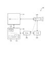
図1は、音響イメージングシステム110及び関連する経食道心エコー(TEE)超音波トランスデューサプローブ120を有するシステム100の1つの例示の実施形態を示す。音響イメージングシステムは、例えば静脈内で実施される最小侵襲性の外科手術のような外科手術の前又は最中に用いられることができる3次元心臓イメージングのような超音波イメージングを提供するために、TEE超音波トランスデューサプローブ120とインタフェースする任意の適切なシステムでありうる。TEE超音波トランスデューサプローブ120は、その遠位端の遠位先端に配置される、例えば1又は2次元音響トランスデューサアレイのような音響トランスデューサを有し、音響トランスデューサは、患者の食道又は胃の中に位置付けられることができる。TEE超音波トランスデューサプローブ120は、関心領域に超音波を送信するために、電子的にステアリングされるマイクロビームフォーミング技術を利用することができる。
FIG. 1 illustrates one exemplary embodiment of a
制御装置130を通じて、オペレータは、TEE超音波トランスデューサプローブ120により生成されるイメージングを最適化するように遠位先端を手動で操作することができる。
Through the
ある実施形態において、制御装置130は、オペレータが1又は複数のケーブルを通じてTEE超音波トランスデューサプローブ120の遠位先端を操作することを可能にする1又は複数の制御ノブを有するハンドルを有することができ、ケーブルは、挿入管を通り、TEE超音波トランスデューサプローブ120の遠位先端から制御ノブまで接続される。ケーブルは、ハンドルの外側に取り付けられる制御ノブを回転させてTEE超音波トランスデューサプローブ120の遠位先端を操作することによって、操作されることができる。
In certain embodiments, the
ある実施形態において、制御装置130は、遠位先端の4方向(2平面)の関節運動及び患者に対する先端の改善された接触を与えることができる。
In certain embodiments, the
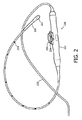
図2は、図1のTEEプローブ120及び制御装置130にそれぞれ対応しうるTEE超音波トランスデューサプローブ220及び関連する制御装置230の1つの例示の実施形態を示す。TEE超音波トランスデューサプローブ220は、その遠位端に配置される遠位先端222を有し、その近位端において制御装置230に接続される。制御装置230は、プローブハンドル232及び1又は複数の制御機構(例えばノブ)234を有する。ある実施形態において、プローブハンドル232の中に、ラック及びピニオンシステムが、その遠位先端222の関節運動を駆動するために、TEE超音波トランスデューサプローブ220のシース内に配置された1つの関節運動ケーブル(プルケーブルとも呼ばれる)に取り付けられることができる。制御ノブ234は、ユーザが制御ノブ234を操作することによって遠位先端222を操作し又は関節運動することを可能にするように、このラック及びピニオンシステムに関連付けられることができる。
FIG. 2 illustrates one exemplary embodiment of a TEE
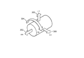
図3は、制御装置230によって提供されることができる、TEE超音波トランスデューサプローブ120の遠位先端を操作するための4つの自由度−前後(surge)302、回転(roll)304、上下(heave)306及び左右(sway)308−を示す。
FIG. 3 illustrates four degrees of freedom for manipulating the distal tip of the TEE
上述したように、場合によって、オペレータは、許容できる物理的制限を越えてTEE超音波トランスデューサプローブ120の遠位先端を不注意に操作することがあり、それにより、患者の食道又は胃に外傷又は損傷をもたらす可能性がある。
As noted above, in some cases, an operator may inadvertently manipulate the distal tip of the TEE
従って、システム100は、患者に配置されるTEE超音波トランスデューサプローブ120の遠位端における遠位先端を操作することに関して、オペレータに触覚フィードバックを提供する。このために、システム100は、処理装置150、ユーザインタフェース140、及びTEE超音波トランスデューサプローブ120の遠位先端と患者との間の接触力に応答する少なくとも1つの接触力応答装置又は手段を有する。ある実施形態において、システム100は、TEE超音波トランスデューサプローブ120の遠位先端に配置される1又は複数の接触力センサ、及び/又は制御装置130に関連付けられる1又は複数の接触力センサを有し、接触力センサは、TEE超音波トランスデューサプローブ120の近位端に配置されることができる。このような接触力応答装置又は手段の例示の実施形態は、以下に更に詳しく記述される。
Accordingly, the
図1の破線は、ある実施形態において、TEE超音波トランスデューサプローブ120の遠位先端に設けられる1又は複数の接触力センサが、処理装置150と通信し、他の実施形態において、制御装置130に関連付けられて提供される1又は複数の接触力センサが、処理装置150と通信することを示している。ある実施形態において、1又は複数の接触力センサは、TEE超音波トランスデューサプローブ120の遠位先端に設けられるとともに制御装置130に関連付けられることができ、これらの接触力センサの各々は、処理装置150と通信する。
The dashed lines in FIG. 1 indicate that in one embodiment, one or more contact force sensors provided at the distal tip of the TEE
処理装置150は、TEE超音波トランスデューサプローブ120の遠位先端に提供され及び/又は制御装置130に関連付けられる1又は複数の接触力センサから、患者と超音波トランスデューサプローブ120の遠位先端との間の接触力に応じた出力信号を生成する。
The
ある実施形態において、処理装置150は、比較器を有することができ、比較器は、患者とTEE超音波トランスデューサプローブ120の遠位先端との間の接触力に応じた出力信号を、閾値と比較し、患者とTEE超音波トランスデューサプローブ120の遠位先端との間の接触力が閾値を越えるときを示すフィードバック信号を生成する。ある実施形態において、閾値は、患者の食道又は胃の外傷又は損傷の予防を確実にするためにTEE超音波トランスデューサプローブ120の遠位先端によって患者に印加されるべきである最大安全接触力を表現することができる。ある実施形態において、閾値は、TEE超音波トランスデューサプローブ120及び/又はシステム100に関する較正プロシージャの間に決定されることができ、それはその部位で実施されることができる。
In some embodiments, the
ある実施形態において、フィードバック信号は更に、接触力が閾値力を越えない場合に接触力と閾値力との間で関係を示すことができる。例えば、ある実施形態において、フィードバック信号は、接触力が閾値力を越えない場合に接触力の相対レベル(例えば閾値力のパーセンテージ)を示すことができ、それにより、閾値接触力が到達されそうか否かをオペレータが評価し判断することを可能にするように、フィードバックがオペレータに提供されることができる。 In certain embodiments, the feedback signal can further indicate a relationship between the contact force and the threshold force if the contact force does not exceed the threshold force. For example, in certain embodiments, the feedback signal can indicate a relative level of contact force (eg, a percentage of the threshold force) if the contact force does not exceed a threshold force, so that the threshold contact force is likely to be reached. Feedback can be provided to the operator to allow the operator to evaluate and determine whether or not.
ある実施形態において、処理装置150は、マイクロプロセッサ、メモリ、及びアナログ−デジタル変換器のような付加の回路を有することができ、これらは、システム100の1又は複数の接触力センサから得られる情報を利用してフィードバック信号を生成するために、用いられることができる。例えば、ある実施形態において、システム100の1又は複数の接触力センサから導き出される1又は複数のアナログ信号は、デジタル信号に変換され、マイクロプロセッサに供給されることができ、メモリに記憶されることができる例えば最大閾値を含む接触力レベルに関する1又は複数の較正された値と比較される。
In certain embodiments, the
ある実施形態において、このような値は、システム100及び/又はTEE超音波トランスデューサプローブ120のための較正プロシージャの間に得られることができる。
In certain embodiments, such values can be obtained during a calibration procedure for
ある実施形態において、処理装置150からのフィードバック信号は、遠位先端と患者との間の接触力が閾値を越える場合にTEE超音波トランスデューサプローブ120の遠位先端の更なる関節運動を阻止し又は防ぐために、制御装置130に提供されることができる。その場合、制御装置130は、触覚フィードバックをユーザ又はオペレータに供給することができ、これは、ユーザが受け取ることができるフィードバックに似ている。例えば、ある実施形態では、TEE超音波トランスデューサプローブの遠位先端と患者との間の接触力が閾値力を越える場合、処理装置150からのフィードバック信号は、制御装置130のサーボモータに、1又は複数の方向における1又は複数の制御機構の更なる移動に対してオペレータが経験する抵抗を増大させるように、提供されることができる。ある実施形態において、TEE超音波トランスデューサプローブの遠位先端と患者との間の接触力が閾値力を越える場合、処理装置150からのフィードバック信号は、制御装置130に、1又は複数の方向における1又は複数の制御機構の更なる移動を阻止又は防止させることができる。
In certain embodiments, the feedback signal from the
ある実施形態において、処理装置150からのフィードバック信号は、接触力が過剰であると考えられ、オペレータによって低減されるべきであるときをオペレータに警告するためにユーザインタフェース140に供給されることができる。ある実施形態において、ユーザインタフェース140は、接触力が閾値力を越えない場合に接触力の相対レベルを示すことができ、それにより、オペレータは、閾値接触力が到達されそうか否かを評価し判断することができる。
In certain embodiments, a feedback signal from the
ある実施形態において、ユーザインタフェース140は、LED142のような1又は複数の照明装置を有することができ、照明装置は、接触力が閾値を越える場合に可視フィードバックをシステム100のオペレータに提供するために、照明され又は点滅する。ある実施形態において、ユーザインタフェースは、異なる色に着色された複数のLEDを有することができ、接触力が閾値を越えるとき、照明されるLEDの色が変わる(例えば、1又は複数の緑色LEDを照明することから1又は複数の赤色LEDを照明することに変わる)。ある実施形態において、ユーザインタフェース140は、複数のLED(例えば5個)を有することができ、照明されるLEDの数は、TEE超音波トランスデューサプローブ120と患者との間の相対接触力に対応する。例えば、接触力が低い場合、ゼロ又は1のLEDが照明されることができ、他方、接触力が閾値を越える場合、LEDの全てが照明されることができる。
In some embodiments, the
ある実施形態において、ユーザインタフェース140は、LCDディスプレイのような表示装置144を有することができる。その場合、ある実施形態において、例えば警告テキストメッセージ(例えば「プローブによって適用される力の量を低減してください」)又はアイコンのような、過剰な接触力の視覚的警告が、LCDディスプレイに供給されることができる。このような視覚的警告は、適当な色を使用して(例えば赤で)表示されることができ、及び/又はオペレータにとってそれらをより目立つようにするためにディスプレイ上で点滅することができる。
In some embodiments, the
ある実施形態において、ユーザインタフェース140は更に、音響イメージングシステム110からの音響画像用の表示装置に組み込まれることができる。その場合、過剰な接触力の視覚的警告は、音響画像を表示するのと同じ表示装置に提供されることができる。
In certain embodiments, the
ある実施形態において、ユーザインタフェース140は、システム100のオペレータに可聴フィードバックを提供するために、ベル、ブザー又はスピーカのようなサウンド生成装置146を有することができる。その場合、TEE超音波トランスデューサプローブ120と患者との間の接触力が閾値を越えるときはいつも、可聴のアラートが提供されることができる。ある実施形態において、TEE超音波トランスデューサプローブ120と患者との間の相対接触力を示す可聴のフィードバック信号が生成されることができる。例えば、可聴信号のボリューム及び/又はピッチは、接触力が増大するにつれて増大されることができる。ある実施形態において、上述の可聴フィードバック装置の1又は複数、及び可視フィードバック装置の1又は複数が一緒に使用されることができ、又はユーザ選択可能でありうる。ユーザインタフェース140を通じたオペレータに対するフィードバックのさまざまな他の形態が企図される。
In certain embodiments, the
フィードバックの上述の形態の一部又は全部が、システム100及びTEE超音波トランスデューサプローブ120のさまざまな実施形態において提供されることができる。
Some or all of the above forms of feedback can be provided in various embodiments of the
図4は、TEE超音波トランスデューサプローブ120と患者との間の接触力が閾値を越える場合にオペレータにフィードバックを提供するプロセス400の1つの例示の実施形態を示す。
FIG. 4 illustrates one exemplary embodiment of a
プロセスは、処理410で始まる。
The process begins at
処理420において、TEE超音波トランスデューサプローブ120の遠位先端を操作するためのオペレータの入力が受け取られるか否かが判定される。
In
処理420において、オペレータの入力が受け取られていないと判定される場合、ステータスが維持され、オペレータに提供されている現在の接触力レベルを示す現在フィードバックは、不変のままであり、動作430において、オペレータに提供されることが続けられる。
If it is determined at
「現在フィードバック」は、アクティブな信号を含まなくてもよく、例えば、現在フィードバックは、現在接触力が閾値より小さい場合にアラームがオフにされる等であってもよいことが理解されるべきである。その場合、例えば、警告ブザー又はLEDは、オフにされることができる等である。 It should be understood that “current feedback” may not include an active signal, for example, current feedback may be that an alarm is turned off, etc., if the current contact force is less than a threshold. is there. In that case, for example, a warning buzzer or LED can be turned off, and so on.
処理420において、オペレータの入力が受け取られると判定される場合、システム100の1又は複数の接触力センサが、処理440においてチェックされる。
If it is determined at
処理450において、オペレータの入力によって接触力圧力が接触力閾値を越えることになるか否かが、接触センサから判定される。上述したように、閾値は、TEE超音波トランスデューサプローブ120及び/又はシステム100のための較正プロシージャの間に決定されることができ、これは、その部位で実施されることができる。
In the
処理450において、オペレータの入力によって接触力圧力が閾値を越えることになると判定される場合、次に処理430において、上述したように、閾値接触力を越えることを示すフィードバックがユーザに供給される。プロセスは、処理420に戻る。
If at
処理450において、オペレータの入力によって接触力圧力が閾値を越えることにならないと判定される場合、処理460において、モータ又は他の駆動手段が、前の処理420においてユーザ入力によって示されるように、TEE超音波トランスデューサプローブ120の遠位先端を操作するためにアクティブにされる。プロセスは、処理420に戻る。
If at
上述のプロセスの多くの変更例が当然ながら可能である。 Many variations of the above process are of course possible.
接触力センサの例示の実施形態が以下に記述される。 Exemplary embodiments of contact force sensors are described below.
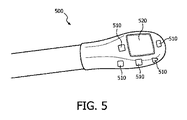
図5は、その遠位端に配置される複数の力感受性抵抗器510及び超音波トランスデューサ520を有するTEE超音波トランスデューサプローブ500の1つの例示の実施形態の一部を示す。TEE超音波トランスデューサプローブ500は、システム300のTEE超音波トランスデューサプローブ120の一実施形態でありうる。
FIG. 5 shows a portion of one exemplary embodiment of a TEE
TEE超音波トランスデューサプローブ500において、力感受性抵抗器510は、TEE超音波トランスデューサプローブ500の遠位先端と患者との間の接触力を直接測定することができる。有利には、力感受性抵抗器510は、患者接触を経験する見込みが最も高いと考えられる遠位先端のロケーションに配置される。図5は、4つの力感受性抵抗器510を有する実施形態を示しているが、原則として、任意の数の力感受性抵抗器510が含まれることができる。より多くの力感受性抵抗器510が配置される場合、遠位先端の任意の部分の過剰な接触力を検出する見込みが増大されることができるが、これは、増大されるシステムの複雑さの代償として得られる。
In the TEE
力感受性抵抗器510の各々の抵抗は、それが経験する接触力の結果として、パッドに対する変形又はひずみに応じて変化する。ある実施形態において、力感受性抵抗器510は、それらに及ぼされる力に基づいてそれらの抵抗を変えるために、特別な設計を利用することができる。この設計は、空気の小さい間隙を層間に有してサンドイッチされる離間された3層を組み込むことができる。その場合、力が、2つの外側の層のいずれかに印加されるとき、外側の層が、内側の層と接触し、それにより、抵抗を低下させる。抵抗のこの低下は、力感受性抵抗器510に及ぼされている力に相関付けられる。印加される力がない場合、力感受性抵抗器510は、ほぼ無限の抵抗を有することができる。
The resistance of each of the force
図6は、力感受性抵抗器の例示の実施形態に関する接触力対抵抗をプロットする。 FIG. 6 plots contact force versus resistance for an exemplary embodiment of a force sensitive resistor.
図6の例示の実施形態において、力感受性抵抗器510の抵抗は、力の値の広いレンジにわたってほぼ直線的に変化することが分かる。ある実施形態において、この線形のレンジにわたって力感受性抵抗器510を動作させることが有利でありえ、又は特に、閾値接触力値が力感受性抵抗器510のこの線形のレンジの範囲内にある力感受性抵抗器510を提供することが有利でありうる。
In the exemplary embodiment of FIG. 6, it can be seen that the resistance of the force
各々の力感受性抵抗器510の抵抗値は、TEE超音波トランスデューサプローブ500の遠位先端と患者との間の接触力が閾値を越えるか否か判定するために、及び/又はある実施形態において、TEE超音波トランスデューサプローブ500の遠位先端と患者との間の相対接触力を(例えば閾値のパーセンテージとして)決定するために、検出されるべきである。
The resistance value of each force
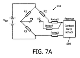
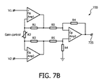
図7A及び図7Bは、力感受性抵抗器510のような接触力センサによって検知される接触力の関数である出力信号を生成するプロセッサの一実施形態の部分を示す。
7A and 7B illustrate portions of one embodiment of a processor that generates an output signal that is a function of contact force sensed by a contact force sensor, such as force
図7Aは、例えば力感受性抵抗器510のような接触力センサの抵抗の関数である信号を生成するために使用されるホイートストンブリッジ710を示す。図7Aにおいて、力感受性抵抗器510は、DC電圧源に電気的に接続され、ホイートストンブリッジ710の中で作動される。力感受性抵抗器510の変形の際、抵抗の変化が回路内で検出される。力感受性抵抗器510の電気抵抗が接触力によって直線的に変わる場合(上述の図6を参照)、ホイートストンブリッジ710から結果として得られる信号の大きさが、増幅され、触覚力測定に容易に相関付けられることができる。図7Bは、このような増幅器720の一実施形態を示す。
FIG. 7A shows a
ある実施形態において、増幅器720は、出力信号725を生成し、出力信号は、遠位先端TEE超音波トランスデューサプローブ500の最大安全接触圧力に対応する閾値電圧と比較されることができる。閾値電圧は、TEE超音波トランスデューサプローブ220、500又はシステム100に関する較正プロシージャを通じて決定されることができる。増幅器720は、閾値電圧との比較のために適切なレンジ内で出力信号を配置するように調整されることができるゲイン制御を有する。
In certain embodiments, the
ある実施形態において、出力信号725は、比較器によって閾値電圧と比較されることができる。ある実施形態において、出力信号725はアナログ−デジタル変換器を通じてデジタル値に変換されることができ、デジタル値は、マイクロプロセッサによって閾値電圧と比較されることができる。他の構成が企図される。
In some embodiments, the
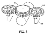
図8は、例えばTEE超音波トランスデューサプローブ120のようなTEE超音波トランスデューサプローブの遠位先端を操作するためのトルク測定ギア機構800の1つの例示の実施形態を示す。この装置において、1又は複数のサーボモータ802が、関連するトルク測定ギア810を作動させるために用いられることができる。トルク測定ギア機構800は、ユーザ又はオペレータが制御ノブとして用いるために提供されることができ、又はより人間工学的観点で親しみやすい制御ノブ構造が、ユーザが制御機構を動作することを可能にするように、トルク測定ギア機構800に提供されることができる。
FIG. 8 illustrates one exemplary embodiment of a torque
図9は、トルク測定ギア810の1つの例示の実施形態を示す。トルク測定ギア810は、内側リング902、外側リング904及び複数のスポーク906を有する。ひずみゲージ910が、スポーク906の1又は複数に設けられる。ひずみゲージ910の1つの一般的なタイプは、金属フォイルパターンを支持する絶縁可撓性バッキングを有する。ゲージは、適切な接着剤によって対象に取り付けられる。トルク測定ギア810が変形されるとき、フォイルが変形され、それにより、その電気抵抗を変化させる。この抵抗変化は、ホイートストンブリッジ(図6Aを参照)を使用して測定されることができ、ゲージ係数として知られる量によりひずみに関連付けられる。
FIG. 9 shows one exemplary embodiment of the
上述したように、ある実施形態において、プローブハンドル内に、ラック及びピニオンシステムが、遠位先端の関節運動を駆動するためにプルケーブル又は関節運動ケーブルに取り付けられることができる。関節運動の物理的制限に近づくとき、ベンディングネック内のこれらのケーブルを囲む圧縮シースが、ケーブル間に引っ張り及び摩擦を生じさせるように大きく収縮することができる。ハンドル上の制御ノブは、回転させるのがますます困難になりうる。トルク測定ギア機構800の1又は複数のトルク測定ギア810の1又は複数のスポーク906は、ハンドルのプルケーブルから伝達されるひずみを経験することができる。トルク測定ギア810上に戦略的に配置されるひずみゲージ910は、上述したように、TEE超音波トランスデューサプローブの遠位先端と患者との間の接触力に関連するフィードバックのために、この機械的変形を電気信号に変換するために使用されることができる。
As described above, in certain embodiments, within the probe handle, a rack and pinion system can be attached to the pull cable or articulation cable to drive articulation of the distal tip. As the physical limits of articulation are approached, the compression sheath that surrounds these cables in the bending neck can shrink significantly to create tension and friction between the cables. The control knob on the handle can become increasingly difficult to rotate. One or
ある実施形態において、関節運動又はプルケーブルによって生成される摩擦力は、システムの使用中に、オープンループフィードバックプロセスを通じて取得され、記憶され、特徴付けられることができる。このデータは、真の触覚力測定を決定するために、ひずみゲージ910によって生成される信号から減算されることができる。図7A及び図7Bに示されるものと同様の検出回路が、TEE超音波トランスデューサプローブ120と患者との間で接触力が閾値を越える場合にオペレータに警告するためのフィードバック信号を生成するために、ひずみゲージ910と共に用いられることができる。
In certain embodiments, frictional forces generated by articulation or pull cables can be acquired, stored and characterized through an open loop feedback process during use of the system. This data can be subtracted from the signal generated by the
好適な実施形態がここに詳しく開示されているが、本発明の概念及び範囲内にある多くの変更例が可能である。このような変更例は、本願の明細書、図面及び請求項の検討の後に当業者に明らかになる。従って、本発明は、添付の請求項の範囲内であること以外に制限されない。 While preferred embodiments are disclosed in detail herein, many variations are possible which are within the concept and scope of the invention. Such modifications will become apparent to those skilled in the art after a review of the specification, drawings, and claims of this application. Accordingly, the invention is not limited except as within the scope of the appended claims.
Claims (20)
前記TEE超音波トランスデューサプローブに接続され、前記TEE超音波トランスデューサプローブからの1又は複数の信号に応じて音響画像を生成する音響イメージングシステムと、
患者に対し前記TEE超音波トランスデューサプローブの前記遠位先端を操作する制御装置と、
前記TEE超音波トランスデューサプローブの前記遠位先端と患者との間の接触力を検知する接触力検知装置と、
前記TEE超音波トランスデューサプローブの前記遠位先端と患者との間の接触力が閾値力を越える場合に、触覚、オーディオ及び視覚フィードバックのうち少なくとも1つを提供するフィードバック機構と、
を有するシステム。 A transesophageal echocardiography (TEE) ultrasound transducer probe having a distal tip at its distal end;
An acoustic imaging system connected to the TEE ultrasonic transducer probe and generating an acoustic image in response to one or more signals from the TEE ultrasonic transducer probe;
A controller for manipulating the distal tip of the TEE ultrasound transducer probe for a patient;
A contact force detection device for detecting a contact force between the distal tip of the TEE ultrasonic transducer probe and a patient;
A feedback mechanism that provides at least one of haptic, audio and visual feedback when the contact force between the distal tip of the TEE ultrasonic transducer probe and a patient exceeds a threshold force;
Having a system.
前記力感受性抵抗器の少なくとも1つに接続されるホイートストンブリッジと、
前記ホイートストンブリッジの出力に接続され、前記出力信号を生成する増幅器と、
を有する、請求項7に記載のシステム。 The processing device is
A Wheatstone bridge connected to at least one of the force sensitive resistors;
An amplifier connected to the output of the Wheatstone bridge for generating the output signal;
8. The system of claim 7, comprising:
少なくとも1つの制御機構と、
前記制御機構が前記遠位先端を操作することができるように、前記制御機構と前記遠位先端との間に接続される少なくとも1つの関節運動ケーブルと、
を有し、前記接触力検知装置が、前記関節運動ケーブルと前記制御機構との間のトルクを検知し、検知されるトルクに応じて前記接触力の関数である出力信号を生成するトルクセンサを有する、請求項1に記載のシステム。 The control device is
At least one control mechanism;
At least one articulation cable connected between the control mechanism and the distal tip so that the control mechanism can manipulate the distal tip;
A torque sensor that detects a torque between the articulation cable and the control mechanism and generates an output signal that is a function of the contact force in accordance with the detected torque. The system of claim 1, comprising:
前記TEE超音波トランスデューサプローブの前記遠位先端と患者との間の接触力を検知するステップと、
前記接触力が閾値を越える場合にフィードバック信号を供給するステップと、
を有する方法。 Manipulating a distal tip at the distal end of a transesophageal echocardiography (TEE) ultrasound transducer probe for a patient;
Sensing a contact force between the distal tip of the TEE ultrasonic transducer probe and a patient;
Providing a feedback signal when the contact force exceeds a threshold;
Having a method.
Applications Claiming Priority (3)
| Application Number | Priority Date | Filing Date | Title |
|---|---|---|---|
| US201461951717P | 2014-03-12 | 2014-03-12 | |
| US61/951,717 | 2014-03-12 | ||
| PCT/IB2015/051507 WO2015136402A1 (en) | 2014-03-12 | 2015-03-02 | System and method of haptic feedback for transesophageal echocardiogram ultrasound transducer probe |
Publications (2)
| Publication Number | Publication Date |
|---|---|
| JP2017506969A true JP2017506969A (en) | 2017-03-16 |
| JP2017506969A5 JP2017506969A5 (en) | 2018-04-12 |
Family
ID=52630448
Family Applications (1)
| Application Number | Title | Priority Date | Filing Date |
|---|---|---|---|
| JP2016555318A Pending JP2017506969A (en) | 2014-03-12 | 2015-03-02 | Tactile feedback system and method for transesophageal echocardiographic ultrasound transducer probe |
Country Status (6)
| Country | Link |
|---|---|
| US (1) | US20170007202A1 (en) |
| EP (1) | EP3116406A1 (en) |
| JP (1) | JP2017506969A (en) |
| CN (1) | CN106102592B (en) |
| RU (1) | RU2016139689A (en) |
| WO (1) | WO2015136402A1 (en) |
Cited By (1)
| Publication number | Priority date | Publication date | Assignee | Title |
|---|---|---|---|---|
| JP2019501728A (en) * | 2016-01-15 | 2019-01-24 | コーニンクレッカ フィリップス エヌ ヴェKoninklijke Philips N.V. | Automated probe steering for clinical views using annotations of a fusion image guidance system |
Families Citing this family (10)
| Publication number | Priority date | Publication date | Assignee | Title |
|---|---|---|---|---|
| US10674997B2 (en) * | 2015-08-10 | 2020-06-09 | Shaohua Hu | Ultrasonic tracking probe and the method |
| KR20180034117A (en) * | 2016-09-27 | 2018-04-04 | 삼성메디슨 주식회사 | Ultrasound diagnostic apparatus and operating method for the same |
| CN109288540A (en) * | 2017-07-24 | 2019-02-01 | 云南师范大学 | A kind of long-distance ultrasonic diagnosis system with touch feedback |
| CN108992086A (en) * | 2017-10-20 | 2018-12-14 | 深圳华大智造科技有限公司 | Supersonic detection device, trolley and ultrasonic system |
| EP3749214B1 (en) * | 2018-02-08 | 2021-09-22 | Koninklijke Philips N.V. | Devices, systems, and methods for transesophageal echocardiography |
| EP3669787A1 (en) * | 2018-12-19 | 2020-06-24 | Koninklijke Philips N.V. | Ultrasound transducer unit with friction guiding function |
| WO2021115905A1 (en) * | 2019-12-12 | 2021-06-17 | Koninklijke Philips N.V. | Intuitive control interface for a robotic tee probe using a hybrid imaging-elastography controller |
| JP2023061910A (en) * | 2021-10-20 | 2023-05-02 | キヤノンメディカルシステムズ株式会社 | Ultrasonic diagnostic apparatus, information processing method, and program |
| EP4248877A1 (en) * | 2022-03-23 | 2023-09-27 | Koninklijke Philips N.V. | Transesophageal transducer to increase patient safety |
| WO2023209093A1 (en) * | 2022-04-27 | 2023-11-02 | Medtecton Gmbh | Ultrasonic rod probe |
Citations (8)
| Publication number | Priority date | Publication date | Assignee | Title |
|---|---|---|---|---|
| JPH06142114A (en) * | 1992-10-30 | 1994-05-24 | Olympus Optical Co Ltd | In-celom treating device |
| JP2006102152A (en) * | 2004-10-05 | 2006-04-20 | National Institute Of Advanced Industrial & Technology | Tactile sensor and tactile sensor device |
| JP2008183097A (en) * | 2007-01-29 | 2008-08-14 | Aloka Co Ltd | Transesophageal probe and ultrasonic diagnostic equipment provided with the same |
| JP2008220530A (en) * | 2007-03-09 | 2008-09-25 | Aloka Co Ltd | Intracavitary probe |
| JP2010187936A (en) * | 2009-02-18 | 2010-09-02 | Fujifilm Corp | Endoscope |
| JP2012513813A (en) * | 2008-12-29 | 2012-06-21 | コーニンクレッカ フィリップス エレクトロニクス エヌ ヴィ | Ultrasonic imaging system with remote control and operation method thereof |
| US20120172731A1 (en) * | 2009-09-15 | 2012-07-05 | St. Jude Medical Systems Ab | Rapid exchange guide unit |
| WO2012153703A1 (en) * | 2011-05-09 | 2012-11-15 | 国立大学法人鳥取大学 | Pressure sensor, endoscope and endoscope device |
Family Cites Families (13)
| Publication number | Priority date | Publication date | Assignee | Title |
|---|---|---|---|---|
| DE60026019T2 (en) * | 1999-05-20 | 2006-08-10 | Eleksen Ltd., Iver Heath | INPUT DEVICE WITH EVALUATION OF MECHANICAL INTERACTIONS |
| GB0407366D0 (en) * | 2004-03-31 | 2004-05-05 | Koninkl Philips Electronics Nv | Textile form touch sensor |
| US8043216B2 (en) * | 2004-06-09 | 2011-10-25 | Hitachi Medical Corporation | Method of displaying elastic image and diagnostic ultrasound system |
| US7839780B2 (en) * | 2006-03-30 | 2010-11-23 | Telcordia Technologies, Inc. | Dynamic traffic rearrangement to enforce policy changes in MPLS networks |
| US8048063B2 (en) * | 2006-06-09 | 2011-11-01 | Endosense Sa | Catheter having tri-axial force sensor |
| JP2008229267A (en) * | 2007-03-23 | 2008-10-02 | Aloka Co Ltd | Ultrasonic diagnostic system, and body cavity probe |
| US8142363B1 (en) * | 2007-07-11 | 2012-03-27 | Pacesetter, Inc. | Cardiac rhythm management lead with omni-directional pressure sensing |
| US8535308B2 (en) * | 2007-10-08 | 2013-09-17 | Biosense Webster (Israel), Ltd. | High-sensitivity pressure-sensing probe |
| US8864757B2 (en) * | 2008-12-31 | 2014-10-21 | St. Jude Medical, Atrial Fibrillation Division, Inc. | System and method for measuring force and torque applied to a catheter electrode tip |
| US8753278B2 (en) * | 2010-09-30 | 2014-06-17 | Siemens Medical Solutions Usa, Inc. | Pressure control in medical diagnostic ultrasound imaging |
| US8532738B2 (en) * | 2010-11-04 | 2013-09-10 | Biosense Webster (Israel), Ltd. | Visualization of catheter-tissue contact by map distortion |
| RU2617809C2 (en) * | 2011-12-08 | 2017-04-26 | Конинклейке Филипс Н.В. | Survey system with multiple ultrasonic transducers |
| US9460029B2 (en) * | 2012-03-02 | 2016-10-04 | Microsoft Technology Licensing, Llc | Pressure sensitive keys |
-
2015
- 2015-03-02 RU RU2016139689A patent/RU2016139689A/en not_active Application Discontinuation
- 2015-03-02 US US15/119,146 patent/US20170007202A1/en not_active Abandoned
- 2015-03-02 JP JP2016555318A patent/JP2017506969A/en active Pending
- 2015-03-02 CN CN201580013329.4A patent/CN106102592B/en active Active
- 2015-03-02 EP EP15708609.1A patent/EP3116406A1/en not_active Withdrawn
- 2015-03-02 WO PCT/IB2015/051507 patent/WO2015136402A1/en active Application Filing
Patent Citations (8)
| Publication number | Priority date | Publication date | Assignee | Title |
|---|---|---|---|---|
| JPH06142114A (en) * | 1992-10-30 | 1994-05-24 | Olympus Optical Co Ltd | In-celom treating device |
| JP2006102152A (en) * | 2004-10-05 | 2006-04-20 | National Institute Of Advanced Industrial & Technology | Tactile sensor and tactile sensor device |
| JP2008183097A (en) * | 2007-01-29 | 2008-08-14 | Aloka Co Ltd | Transesophageal probe and ultrasonic diagnostic equipment provided with the same |
| JP2008220530A (en) * | 2007-03-09 | 2008-09-25 | Aloka Co Ltd | Intracavitary probe |
| JP2012513813A (en) * | 2008-12-29 | 2012-06-21 | コーニンクレッカ フィリップス エレクトロニクス エヌ ヴィ | Ultrasonic imaging system with remote control and operation method thereof |
| JP2010187936A (en) * | 2009-02-18 | 2010-09-02 | Fujifilm Corp | Endoscope |
| US20120172731A1 (en) * | 2009-09-15 | 2012-07-05 | St. Jude Medical Systems Ab | Rapid exchange guide unit |
| WO2012153703A1 (en) * | 2011-05-09 | 2012-11-15 | 国立大学法人鳥取大学 | Pressure sensor, endoscope and endoscope device |
Cited By (1)
| Publication number | Priority date | Publication date | Assignee | Title |
|---|---|---|---|---|
| JP2019501728A (en) * | 2016-01-15 | 2019-01-24 | コーニンクレッカ フィリップス エヌ ヴェKoninklijke Philips N.V. | Automated probe steering for clinical views using annotations of a fusion image guidance system |
Also Published As
| Publication number | Publication date |
|---|---|
| CN106102592B (en) | 2021-01-22 |
| RU2016139689A (en) | 2018-04-12 |
| EP3116406A1 (en) | 2017-01-18 |
| RU2016139689A3 (en) | 2018-10-15 |
| US20170007202A1 (en) | 2017-01-12 |
| CN106102592A (en) | 2016-11-09 |
| WO2015136402A1 (en) | 2015-09-17 |
Similar Documents
| Publication | Publication Date | Title |
|---|---|---|
| JP2017506969A (en) | Tactile feedback system and method for transesophageal echocardiographic ultrasound transducer probe | |
| JP6980065B2 (en) | Robotic surgical system Torque conversion detection | |
| US5351677A (en) | Medical system having object information reproduction means for palpation | |
| JP2017506969A5 (en) | ||
| EP2135635B1 (en) | Linear object driving device | |
| US20070074584A1 (en) | Gentle touch surgical instrument and method of using same | |
| WO2015118773A1 (en) | Insertion device | |
| JP2014501557A5 (en) | ||
| JP3872210B2 (en) | Catheter operation simulator and simulation method using the same | |
| JP6109470B2 (en) | Catheter tangle indication | |
| JPH06154154A (en) | Insertion device in duct | |
| US20190076092A1 (en) | Advanced control features for steering devices for intravascular devices and associated systems and methods | |
| KR101031501B1 (en) | Connection confirmation device for probe of ultrasound diagnosis apparatus | |
| JPH11178932A (en) | Device for inserting into organism | |
| JP2011019550A (en) | Endoscope apparatus, endoscope system, and method of controlling endoscope apparatus | |
| US20190239945A1 (en) | Catheter handle with ring color indicators | |
| JP3312904B2 (en) | Diagnostic system | |
| JP6675678B2 (en) | Forceps instrument and pressure sensor | |
| WO2017170777A1 (en) | Endoscopic shape ascertainment system | |
| JP7267754B2 (en) | Biological information monitor and biological information measuring system | |
| Vajpeyi et al. | A Novel, Flexible, Full-Length, Pressure-Sensing Sleeve for Colonoscopes | |
| WO2021199901A1 (en) | Medical device for acquiring image, and medical system | |
| WO2023026316A1 (en) | Ultrasonic diagnostic device and program therefor | |
| JPH0352739B2 (en) | ||
| JPWO2015037036A1 (en) | Diagnostic imaging apparatus and control method thereof |
Legal Events
| Date | Code | Title | Description |
|---|---|---|---|
| RD04 | Notification of resignation of power of attorney |
Free format text: JAPANESE INTERMEDIATE CODE: A7424 Effective date: 20170214 |
|
| A521 | Request for written amendment filed |
Free format text: JAPANESE INTERMEDIATE CODE: A523 Effective date: 20180301 |
|
| A621 | Written request for application examination |
Free format text: JAPANESE INTERMEDIATE CODE: A621 Effective date: 20180301 |
|
| A977 | Report on retrieval |
Free format text: JAPANESE INTERMEDIATE CODE: A971007 Effective date: 20181010 |
|
| A131 | Notification of reasons for refusal |
Free format text: JAPANESE INTERMEDIATE CODE: A131 Effective date: 20181023 |
|
| A601 | Written request for extension of time |
Free format text: JAPANESE INTERMEDIATE CODE: A601 Effective date: 20190117 |
|
| A521 | Request for written amendment filed |
Free format text: JAPANESE INTERMEDIATE CODE: A523 Effective date: 20190419 |
|
| A02 | Decision of refusal |
Free format text: JAPANESE INTERMEDIATE CODE: A02 Effective date: 20190903 |
|
| A521 | Request for written amendment filed |
Free format text: JAPANESE INTERMEDIATE CODE: A523 Effective date: 20191220 |
|
| C60 | Trial request (containing other claim documents, opposition documents) |
Free format text: JAPANESE INTERMEDIATE CODE: C60 Effective date: 20191220 |
|
| C11 | Written invitation by the commissioner to file amendments |
Free format text: JAPANESE INTERMEDIATE CODE: C11 Effective date: 20200107 |
|
| A911 | Transfer to examiner for re-examination before appeal (zenchi) |
Free format text: JAPANESE INTERMEDIATE CODE: A911 Effective date: 20200203 |
|
| C21 | Notice of transfer of a case for reconsideration by examiners before appeal proceedings |
Free format text: JAPANESE INTERMEDIATE CODE: C21 Effective date: 20200204 |
|
| A912 | Re-examination (zenchi) completed and case transferred to appeal board |
Free format text: JAPANESE INTERMEDIATE CODE: A912 Effective date: 20200221 |
|
| C211 | Notice of termination of reconsideration by examiners before appeal proceedings |
Free format text: JAPANESE INTERMEDIATE CODE: C211 Effective date: 20200227 |
|
| C22 | Notice of designation (change) of administrative judge |
Free format text: JAPANESE INTERMEDIATE CODE: C22 Effective date: 20200402 |
|
| C23 | Notice of termination of proceedings |
Free format text: JAPANESE INTERMEDIATE CODE: C23 Effective date: 20200721 |
|
| C03 | Trial/appeal decision taken |
Free format text: JAPANESE INTERMEDIATE CODE: C03 Effective date: 20200818 |
|
| C30A | Notification sent |
Free format text: JAPANESE INTERMEDIATE CODE: C3012 Effective date: 20200818 |