JP2017503951A - Liquid drain device for aircraft engines - Google Patents
Liquid drain device for aircraft engines Download PDFInfo
- Publication number
- JP2017503951A JP2017503951A JP2016539936A JP2016539936A JP2017503951A JP 2017503951 A JP2017503951 A JP 2017503951A JP 2016539936 A JP2016539936 A JP 2016539936A JP 2016539936 A JP2016539936 A JP 2016539936A JP 2017503951 A JP2017503951 A JP 2017503951A
- Authority
- JP
- Japan
- Prior art keywords
- liquid
- collector
- engine
- line
- drain
- Prior art date
- Legal status (The legal status is an assumption and is not a legal conclusion. Google has not performed a legal analysis and makes no representation as to the accuracy of the status listed.)
- Pending
Links
- 239000007788 liquid Substances 0.000 title claims abstract description 100
- 238000005086 pumping Methods 0.000 claims abstract description 40
- 238000012544 monitoring process Methods 0.000 claims abstract description 28
- 230000002159 abnormal effect Effects 0.000 claims abstract description 11
- 238000007599 discharging Methods 0.000 claims abstract description 6
- 239000007789 gas Substances 0.000 claims description 42
- 238000002347 injection Methods 0.000 claims description 18
- 239000007924 injection Substances 0.000 claims description 18
- 238000000034 method Methods 0.000 claims description 6
- 230000000007 visual effect Effects 0.000 claims description 6
- 239000000567 combustion gas Substances 0.000 claims description 2
- 230000001419 dependent effect Effects 0.000 claims 1
- 239000000446 fuel Substances 0.000 description 10
- 238000012423 maintenance Methods 0.000 description 8
- 239000012530 fluid Substances 0.000 description 6
- 239000000243 solution Substances 0.000 description 5
- 238000002485 combustion reaction Methods 0.000 description 3
- 238000000605 extraction Methods 0.000 description 2
- 238000007689 inspection Methods 0.000 description 2
- 239000007921 spray Substances 0.000 description 2
- 230000004913 activation Effects 0.000 description 1
- 238000004891 communication Methods 0.000 description 1
- 230000006835 compression Effects 0.000 description 1
- 238000007906 compression Methods 0.000 description 1
- 238000012790 confirmation Methods 0.000 description 1
- 238000011109 contamination Methods 0.000 description 1
- 230000007547 defect Effects 0.000 description 1
- 230000002950 deficient Effects 0.000 description 1
- 239000002828 fuel tank Substances 0.000 description 1
- 239000012535 impurity Substances 0.000 description 1
- 230000002452 interceptive effect Effects 0.000 description 1
- 230000007257 malfunction Effects 0.000 description 1
- 238000012806 monitoring device Methods 0.000 description 1
- 239000003973 paint Substances 0.000 description 1
- 230000000737 periodic effect Effects 0.000 description 1
- 230000002028 premature Effects 0.000 description 1
- 238000012545 processing Methods 0.000 description 1
- 238000010926 purge Methods 0.000 description 1
- 238000011084 recovery Methods 0.000 description 1
- 239000000779 smoke Substances 0.000 description 1
- 238000011144 upstream manufacturing Methods 0.000 description 1
- XLYOFNOQVPJJNP-UHFFFAOYSA-N water Substances O XLYOFNOQVPJJNP-UHFFFAOYSA-N 0.000 description 1
Images


Classifications
-
- F—MECHANICAL ENGINEERING; LIGHTING; HEATING; WEAPONS; BLASTING
- F02—COMBUSTION ENGINES; HOT-GAS OR COMBUSTION-PRODUCT ENGINE PLANTS
- F02C—GAS-TURBINE PLANTS; AIR INTAKES FOR JET-PROPULSION PLANTS; CONTROLLING FUEL SUPPLY IN AIR-BREATHING JET-PROPULSION PLANTS
- F02C7/00—Features, components parts, details or accessories, not provided for in, or of interest apart form groups F02C1/00 - F02C6/00; Air intakes for jet-propulsion plants
- F02C7/22—Fuel supply systems
- F02C7/232—Fuel valves; Draining valves or systems
-
- B—PERFORMING OPERATIONS; TRANSPORTING
- B64—AIRCRAFT; AVIATION; COSMONAUTICS
- B64C—AEROPLANES; HELICOPTERS
- B64C1/00—Fuselages; Constructional features common to fuselages, wings, stabilising surfaces or the like
- B64C1/14—Windows; Doors; Hatch covers or access panels; Surrounding frame structures; Canopies; Windscreens accessories therefor, e.g. pressure sensors, water deflectors, hinges, seals, handles, latches, windscreen wipers
- B64C1/1407—Doors; surrounding frames
- B64C1/1453—Drain masts
-
- B—PERFORMING OPERATIONS; TRANSPORTING
- B64—AIRCRAFT; AVIATION; COSMONAUTICS
- B64D—EQUIPMENT FOR FITTING IN OR TO AIRCRAFT; FLIGHT SUITS; PARACHUTES; ARRANGEMENTS OR MOUNTING OF POWER PLANTS OR PROPULSION TRANSMISSIONS IN AIRCRAFT
- B64D45/00—Aircraft indicators or protectors not otherwise provided for
-
- F—MECHANICAL ENGINEERING; LIGHTING; HEATING; WEAPONS; BLASTING
- F01—MACHINES OR ENGINES IN GENERAL; ENGINE PLANTS IN GENERAL; STEAM ENGINES
- F01M—LUBRICATING OF MACHINES OR ENGINES IN GENERAL; LUBRICATING INTERNAL COMBUSTION ENGINES; CRANKCASE VENTILATING
- F01M11/00—Component parts, details or accessories, not provided for in, or of interest apart from, groups F01M1/00 - F01M9/00
- F01M11/04—Filling or draining lubricant of or from machines or engines
- F01M11/0458—Lubricant filling and draining
-
- F—MECHANICAL ENGINEERING; LIGHTING; HEATING; WEAPONS; BLASTING
- F02—COMBUSTION ENGINES; HOT-GAS OR COMBUSTION-PRODUCT ENGINE PLANTS
- F02C—GAS-TURBINE PLANTS; AIR INTAKES FOR JET-PROPULSION PLANTS; CONTROLLING FUEL SUPPLY IN AIR-BREATHING JET-PROPULSION PLANTS
- F02C9/00—Controlling gas-turbine plants; Controlling fuel supply in air- breathing jet-propulsion plants
- F02C9/26—Control of fuel supply
-
- B—PERFORMING OPERATIONS; TRANSPORTING
- B64—AIRCRAFT; AVIATION; COSMONAUTICS
- B64D—EQUIPMENT FOR FITTING IN OR TO AIRCRAFT; FLIGHT SUITS; PARACHUTES; ARRANGEMENTS OR MOUNTING OF POWER PLANTS OR PROPULSION TRANSMISSIONS IN AIRCRAFT
- B64D37/00—Arrangements in connection with fuel supply for power plant
- B64D37/02—Tanks
- B64D37/14—Filling or emptying
- B64D37/20—Emptying systems
- B64D37/26—Jettisoning of fuel
-
- F—MECHANICAL ENGINEERING; LIGHTING; HEATING; WEAPONS; BLASTING
- F05—INDEXING SCHEMES RELATING TO ENGINES OR PUMPS IN VARIOUS SUBCLASSES OF CLASSES F01-F04
- F05D—INDEXING SCHEME FOR ASPECTS RELATING TO NON-POSITIVE-DISPLACEMENT MACHINES OR ENGINES, GAS-TURBINES OR JET-PROPULSION PLANTS
- F05D2220/00—Application
- F05D2220/30—Application in turbines
- F05D2220/32—Application in turbines in gas turbines
- F05D2220/329—Application in turbines in gas turbines in helicopters
-
- F—MECHANICAL ENGINEERING; LIGHTING; HEATING; WEAPONS; BLASTING
- F05—INDEXING SCHEMES RELATING TO ENGINES OR PUMPS IN VARIOUS SUBCLASSES OF CLASSES F01-F04
- F05D—INDEXING SCHEME FOR ASPECTS RELATING TO NON-POSITIVE-DISPLACEMENT MACHINES OR ENGINES, GAS-TURBINES OR JET-PROPULSION PLANTS
- F05D2260/00—Function
- F05D2260/60—Fluid transfer
- F05D2260/601—Fluid transfer using an ejector or a jet pump
-
- F—MECHANICAL ENGINEERING; LIGHTING; HEATING; WEAPONS; BLASTING
- F05—INDEXING SCHEMES RELATING TO ENGINES OR PUMPS IN VARIOUS SUBCLASSES OF CLASSES F01-F04
- F05D—INDEXING SCHEME FOR ASPECTS RELATING TO NON-POSITIVE-DISPLACEMENT MACHINES OR ENGINES, GAS-TURBINES OR JET-PROPULSION PLANTS
- F05D2260/00—Function
- F05D2260/60—Fluid transfer
- F05D2260/602—Drainage
-
- F—MECHANICAL ENGINEERING; LIGHTING; HEATING; WEAPONS; BLASTING
- F05—INDEXING SCHEMES RELATING TO ENGINES OR PUMPS IN VARIOUS SUBCLASSES OF CLASSES F01-F04
- F05D—INDEXING SCHEME FOR ASPECTS RELATING TO NON-POSITIVE-DISPLACEMENT MACHINES OR ENGINES, GAS-TURBINES OR JET-PROPULSION PLANTS
- F05D2270/00—Control
- F05D2270/80—Devices generating input signals, e.g. transducers, sensors, cameras or strain gauges
Abstract
エンジンからドレイン液体を収集するように設計された収集器(11)を備える、航空エンジン(1)用の液体ドレイン装置(10)であって、前記装置は、収集器内に保持された液体をポンピングする、前記液体を排出する手段(13、19)と、異常な様態で液体が収集器によって収集されるとそれを表示するように設計された監視手段(14)とを備え、前記監視手段は、収集される液体の流量がポンピング手段の送達量よりも大きくなると作動されるように設計されることを特徴とする、液体ドレイン装置(10)。A liquid drain device (10) for an aircraft engine (1) comprising a collector (11) designed to collect drain liquid from the engine, said device holding the liquid held in the collector Means for pumping and discharging said liquid (13, 19) and monitoring means (14) designed to indicate when liquid is collected by the collector in an abnormal manner, said monitoring means The liquid drain device (10), characterized in that it is designed to be activated when the flow rate of the collected liquid is greater than the delivered amount of the pumping means.
Description
本発明は、航空機エンジン用の液体ドレイン装置と、そのような装置を備える航空機エンジンと、前記エンジンを検査する方法とに関する。 The present invention relates to a liquid drain device for an aircraft engine, an aircraft engine comprising such a device, and a method for inspecting said engine.
ヘリコプタなどの航空機用エンジンではしばしば、様々なタイプの液体、例えば燃料または油を、前記液体が蓄積し、前記エンジンの作動を妨げるのを防止するために、排出することが必要である。例えば、一部のエンジンはパージ動作を必要とするが、これは液体(燃料、油など)の損失を生じ、液体は回収および処理されなければならない。 In aircraft engines such as helicopters, it is often necessary to discharge various types of liquids, such as fuel or oil, to prevent the liquid from accumulating and interfering with the operation of the engine. For example, some engines require a purge operation, which results in loss of liquid (fuel, oil, etc.) and the liquid must be recovered and processed.
現在の技術状況では、前記液体を回収するために帰還タンクが設けられる。即ち、液体を航空機の燃料タンクに搬送するために少なくとも1本のダクトが設けられる。しかしながら、この技術はいくつかの欠点を有する。実際、航空機の製造業者は、エンジンからドレインされた様々な液体を回収するのに使用される前記帰還タンクを設けることを強いられている。この技術的制約は、前記液体の流量および温度が高い場合があるという事実によって悪化される。「潜在的」欠陥から漏れが発生する可能性もある。さらに、回収された油がタンク内に保管された燃料を汚染する。したがって、これらの潜在的な漏れに対処しなければならないということは、航空機製造業者に大きな制限を課し、帰還タンクを持たないエンジンを航空機上に組み込む助けとならない。 In the current state of the art, a return tank is provided to collect the liquid. That is, at least one duct is provided for transporting liquid to the aircraft fuel tank. However, this technique has several drawbacks. In fact, aircraft manufacturers are forced to provide the return tank that is used to collect various liquids drained from the engine. This technical constraint is exacerbated by the fact that the liquid flow rate and temperature may be high. Leakage can also occur from “potential” defects. Furthermore, the recovered oil contaminates the fuel stored in the tank. Therefore, having to deal with these potential leaks places significant limitations on aircraft manufacturers and does not help to incorporate engines on the aircraft that do not have a return tank.
加えて、欠陥のあるシールを有する一部の部品の結果としてエンジン内で油または燃料漏れが起こる可能性があるが、これはまだ前記部品の作動に実際に影響を及ぼさない場合がある。現在の技術状況では、このタイプの漏れを検出すると直ちにメンテナンス作業が実施される。これはエンジン上に悪い影響を有さないが、これらの作業の頻度と航空機エンジンの総メンテナンス費用とを増加させる。このことは、特に、外部の漏れを動的シールが生じさせる可能性があるHMU油圧機械式システムで特に当てはまる。駆動部のドレイン領域内の燃料漏れが、ポンプユニット/HMUが取り外される主な理由であるが、それでも前記漏れがエンジンの作動に顕著な影響を有することはない。したがって、動的シールが完全ではなくとも、HMU油圧機械式システムを維持することが可能であれば望ましい。 In addition, oil or fuel leaks may occur in the engine as a result of some parts having defective seals, which may not actually affect the operation of the parts yet. In the current state of the art, maintenance work is performed as soon as this type of leak is detected. This has no negative impact on the engine, but increases the frequency of these operations and the total maintenance cost of the aircraft engine. This is especially true in HMU hydromechanical systems where dynamic seals can cause external leaks. Although fuel leaks in the drain region of the drive are the main reason that the pump unit / HMU is removed, the leaks still do not have a significant impact on engine operation. It is therefore desirable if it is possible to maintain an HMU hydromechanical system even if the dynamic seal is not perfect.
航空機エンジンからドレイン液体を排出するためにいくつかの解決策が知られているが、それらには、上に明記された問題および必須要件に効果的かつ充分に取り組んでいるものはない。例えば、1つの解決策として、ドレイン液体をエンジンデッキの排水口に排出することがある。この解決策は、液体が大気中または滑走路上へ投棄されることにつながり、これが益々許容されなくなってきていることから、満足のゆくものとは言えない。他の解決策として、液体をドレインする処理装置を設けることがあり、前記装置はエンジンからドレイン液体を収集するように設計された収集器を備える。この収集器は、ドレイン液が収集器からそれらが燃焼される噴射ノズルに搬送およびポンピングされるように、ダクトによってエンジンの排出ノズルに連結されることが可能である。この場合、噴射ノズルの出口に炎および煙が現れる場合があり、これは、特にエンジンが始動されるとき見るのに心地の良いものではない。 Several solutions are known for draining drain liquids from aircraft engines, but none effectively and fully address the problems and requirements specified above. For example, one solution is to drain the drain liquid to the engine deck drain. This solution is not satisfactory as it leads to liquid being dumped into the atmosphere or on the runway, which is becoming increasingly unacceptable. Another solution is to provide a processing device for draining liquid, said device comprising a collector designed to collect drain liquid from the engine. This collector can be connected by a duct to the exhaust nozzle of the engine so that the drain liquid is transported and pumped from the collector to the injection nozzle where they are combusted. In this case, flames and smoke may appear at the outlet of the injection nozzle, which is not particularly comfortable to see when the engine is started.
本発明の目的は、上に明記された問題および必須要件に対する解決策を見出すことである。 The object of the present invention is to find a solution to the problems and essential requirements specified above.
本発明は、エンジンから排出される液体を収集するように設計された収集器を備える航空機エンジン用の液体ドレイン装置に関する。 The present invention relates to a liquid drain device for an aircraft engine comprising a collector designed to collect liquid discharged from the engine.
本発明によれば、前記ドレイン装置は、収集器内に保持された液体をポンピングする、および前記液体を排出する手段と、異常な様態で液体が収集器によって収集されるとそれを知らせるように設計された監視手段とを備え、前記監視手段は、収集された液体の流量がポンピング手段の送達量よりも大きくなると作動されるように設計されることを特徴とする。 According to the present invention, the drain device is adapted to pump the liquid held in the collector and to discharge the liquid and to inform when liquid is collected by the collector in an abnormal manner. Designed monitoring means, said monitoring means being designed to be activated when the flow rate of the collected liquid is greater than the delivered amount of the pumping means.
従来技術のように、収集器はエンジンから様々な液体(油、燃料など)を回収する。ポンピングおよび排出手段は、液体を排出するためにそれらが収集器からポンピングされることを可能にする。最後に、監視手段は収集される液体の流量が監視されることを可能にし、この流量が異常であるとそれを検出することを可能にする。前記流量は、それがポンピング手段の送達量よりも大きいとき、異常である。 As in the prior art, the collector collects various liquids (oil, fuel, etc.) from the engine. The pumping and draining means allow them to be pumped from the collector to drain the liquid. Finally, the monitoring means makes it possible to monitor the flow rate of the collected liquid and to detect if this flow rate is abnormal. The flow rate is abnormal when it is greater than the delivery amount of the pumping means.
したがって、ポンピングの送達量は、エンジンの正常な作動、即ち、生じる場合のある液体の損失および漏れがエンジンの作動に影響を及ぼさない作動に対応する閾値(例えば凡そ毎時数リットル)に設定されることが好ましい(即ち、エンジンの故障が発生している場合を除いて)。言い換えれば、正常動作中、ポンピング手段は、前記ポンピング手段が作動中であるとき収集器内に収集された液体を全て排出する。他方、誤動作および大量の液漏れの際には、即ちエンジンの故障が発生しているとき、ポンピング手段の送達量は、収集器内に収集された液体を排出するのにもはや充分ではない。このように監視手段は作動され、このようにこの異常な状態を検出するように設計される。エンジン上でメンテナンス作業が実施されることが可能である。このように、本発明による装置の監視手段は、メンテナンス作業を、ドレイン液体の大量の漏れが検出されるときのそうした場合に限定することを可能にし、このことは、殊にエンジンのメンテナンス費用の点で特に有利である。このように監視手段は、エンジンの部品が時期尚早に取り外されるのを防止し、従来技術の定期検査を最小限に抑える。 Thus, the pumping delivery volume is set to a threshold (eg, approximately a few liters per hour) that corresponds to normal operation of the engine, ie, any loss of fluid that may occur and leakage that does not affect engine operation. (Ie, unless an engine failure has occurred). In other words, during normal operation, the pumping means drains all of the liquid collected in the collector when the pumping means is in operation. On the other hand, in the event of a malfunction and a large amount of liquid leakage, i.e. when an engine failure has occurred, the delivery volume of the pumping means is no longer sufficient to drain the liquid collected in the collector. Thus, the monitoring means is activated and is thus designed to detect this abnormal condition. Maintenance work can be performed on the engine. In this way, the monitoring means of the device according to the invention makes it possible to limit the maintenance work to such a case when a large leak of drain liquid is detected, which in particular reduces the maintenance costs of the engine. This is particularly advantageous. Thus, the monitoring means prevents premature removal of engine parts and minimizes prior art periodic inspections.
本発明によるドレイン装置は、航空機製造業者との接触を最小限に抑え、帰還タンクを有することを不必要にする。有利なことに、ドレイン装置はこのように帰還タンクを有さない。 The drain device according to the present invention minimizes contact with aircraft manufacturers and makes it unnecessary to have a return tank. Advantageously, the drain device thus does not have a return tank.
本発明の特定の実施形態によると、ポンピング手段は電気、機械、または気体ポンプを備える。 According to a particular embodiment of the invention, the pumping means comprises an electric, mechanical or gas pump.
変化形態では、ポンピング手段は、噴射ポンプエジェクタを備えることが可能である。このエジェクタは、収集器内に保持された液体用の入口を一方端部が形成し、液体を排出する出口を他方端部が形成する第1ラインと、加圧ガスを霧化する第2ラインにおいて、第1ラインの周りまたは内側に延在し、前記第2ラインを出てゆく霧化ガスが液体に対して第1ラインの出口を通って排出されることを強制するように設計された第2ラインとを備えることが可能である。 In a variant, the pumping means can comprise an injection pump ejector. This ejector has a first line in which one end forms an inlet for liquid held in the collector and a second line forms an outlet for discharging liquid, and a second line for atomizing pressurized gas. In which the atomizing gas extending around or inward of the first line and exiting the second line is designed to force the liquid to be discharged through the outlet of the first line A second line.
第1ラインは、弁、例えばフラップ弁に連結されることが可能である。一実施形態では、この弁は電気的または機械的に制御される。変化形態では、前記弁は加圧流体によって制御されることが可能であり、弁は、流体圧力が特定の閾値未満であると閉鎖され、前記圧力がこの閾値を超えると開く。このように弁は、第1ライン内のドレイン液体の流れを制御することを可能にする。このことは、例えばエンジンが点火される際にドレイン液体が排出されないように、それらが排出される時間を精確に制御することを可能にすることが可能である。 The first line can be connected to a valve, such as a flap valve. In one embodiment, the valve is controlled electrically or mechanically. In a variation, the valve can be controlled by pressurized fluid, and the valve is closed when the fluid pressure is below a certain threshold and opens when the pressure exceeds this threshold. The valve thus makes it possible to control the flow of drain liquid in the first line. This can make it possible to precisely control the time that they are drained, for example so that drain liquid is not drained when the engine is ignited.
エジェクタの第2ラインは、例えばエンジンの圧縮機から加圧ガスを抽気する手段に連結されたガス入口を備えることが可能である。エジェクタの第2ラインのガス入口は、弁、例えばフラップ弁、または流れ断面積を絞る手段によって抽気手段に連結されることが可能である。この弁は電気、機械、または気体(加圧流体によって制御される)によることが可能である。弁は抽かれた加圧ガスによって制御されることが可能である。この場合、上で説明されたように、前記弁は、ガス圧力が特定の閾値未満であると閉鎖され、前記圧力がこの閾値を超えると開く。このことは、フラップ弁が自律的に作動することから特に有利であり、加圧ガスは、それらの圧力がフラップ弁を開けるのに充分であると、エジェクタの第2ラインにガス供給する。フラップ弁は、例えば、航空機が飛行中であり、エンジンが巡航モードにあると開くように設計されることが可能である。 The second line of the ejector may comprise a gas inlet connected to a means for extracting pressurized gas from the compressor of the engine, for example. The gas inlet of the second line of the ejector can be connected to the bleed means by a valve, such as a flap valve, or a means for reducing the flow cross-sectional area. This valve can be electric, mechanical, or gas (controlled by pressurized fluid). The valve can be controlled by the extracted pressurized gas. In this case, as explained above, the valve is closed when the gas pressure is below a certain threshold and opens when the pressure exceeds this threshold. This is particularly advantageous since the flap valves operate autonomously, and the pressurized gases gas the second line of the ejector if their pressure is sufficient to open the flap valves. The flap valve can be designed, for example, to open when the aircraft is in flight and the engine is in cruise mode.
一実施形態によると、ポンピング手段は収集器内に組み込まれる。言い換えれば、ポンピング手段は収集器内または収集器上に取り付けられ、それによって装置のサイズを縮小する。ポンピング手段が上述のタイプのエジェクタを備える場合、前記エジェクタの第2ラインは収集器内に前記収集器からドレイン液体用出口の領域内で取り付けられることが可能であり、このようにその出口はエジェクタの第1ラインを形成する。変化形態では、ポンピング手段は収集器から間隔を置いて位置付けられ、導管によってその液体出口に連結される。 According to one embodiment, the pumping means are incorporated in the collector. In other words, the pumping means is mounted in or on the collector, thereby reducing the size of the device. If the pumping means comprises an ejector of the type described above, the second line of the ejector can be installed in the collector in the region of the outlet for the drain liquid from the collector, so that the outlet is ejector. Forming the first line. In a variant, the pumping means is positioned at a distance from the collector and is connected to its liquid outlet by a conduit.
監視手段は、収集器を検査する操作者に見えるよう、または航空機のコックピットに向けられた信号を発するように設計された視覚および/または電気警報器を備えることが好ましい。警報器は、収集器を満たしている流量がポンピング手段の送達量よりも大きくなると起動される。前記警報器は、上で説明されたようにエンジン内の異常な漏れが知らされることを可能にする。変化形態では、監視手段は収集器内に設けられた検査用穴または窓を備えることが可能である。このように操作者は収集器内の液体の高さまたは量を確認し、メンテナンス作業を実施するか否かを決定することが可能である。いくつかの流量の閾値を監視して、故障の進み具合を観察し、確認の予定を組むことも可能である。 The monitoring means preferably comprises a visual and / or electrical alarm designed to be visible to an operator inspecting the collector or to emit a signal directed to the aircraft cockpit. The alarm is activated when the flow rate filling the collector is greater than the delivered amount of the pumping means. The alarm allows an abnormal leak in the engine to be informed as explained above. In a variant, the monitoring means may comprise an inspection hole or window provided in the collector. In this way, the operator can check the height or amount of liquid in the collector and decide whether or not to perform maintenance work. It is also possible to monitor several flow thresholds, observe the progress of the failure and schedule a confirmation.
有利なことに、収集器の監視手段は、収集された液体の流量がポンピング手段の送達量よりも大きくなると、液体を収集器から逃がすように設計されたオーバーフロー部を備える。このように、故障の場合とは別に油または燃料の外側への流れが防止される。このような流れが発生すると仮定した場合、操作者は、例えばオーバーフロー部のドリップマークによって、大き過ぎる流量の液体を収集器が受け取っていることを容易に確定することが可能となる。そうすると前記操作者は、メンテナンス作業を実施するか否かを決定することが可能となる。 Advantageously, the monitoring means of the collector comprises an overflow designed to allow liquid to escape from the collector when the flow rate of the collected liquid is greater than the delivered amount of the pumping means. In this way, the flow of oil or fuel to the outside is prevented separately from the case of failure. Assuming that such a flow occurs, the operator can easily determine that the collector is receiving a flow of liquid that is too large, for example by a drip mark in the overflow section. Then, the operator can determine whether or not to perform maintenance work.
本発明は、燃焼ガス用の排出ノズルを備える航空機エンジンにも関する。このエンジンは、本発明による少なくとも1つのドレイン装置を備え、ポンピング手段の出口は直接または導管によって噴射ノズルの中へ通じることを特徴とする。 The invention also relates to an aircraft engine comprising an exhaust nozzle for combustion gases. This engine comprises at least one drain device according to the invention, characterized in that the outlet of the pumping means leads directly or via a conduit into the injection nozzle.
このように、収集器から排出されたドレイン液体は、それらが燃焼されるエンジンの排出ノズルに搬送される。上で説明されたように、ドレイン液体が排出される時間は、例えばポンピング手段を形成する噴射ポンプエジェクタの第1または第2ラインに連結されたフラップ弁によって前もって決定されることが可能である。このように、航空機が飛行中であるとき、外部への汚染を最小限に抑えるように、ドレイン液体を噴射ノズルの中のみへ排出することも考えられる。 In this way, the drain liquid discharged from the collector is conveyed to the discharge nozzle of the engine where it is burned. As explained above, the time at which the drain liquid is drained can be determined in advance, for example by a flap valve connected to the first or second line of the injection pump ejector forming the pumping means. Thus, it is conceivable to drain the drain liquid only into the injection nozzle so as to minimize external contamination when the aircraft is in flight.
有利なことに、ポンピング手段は、圧縮機、あるいはエンジンからガスを除去するシステムのいずれかから、ガスを抽気する手段に連結される。 Advantageously, the pumping means is coupled to means for extracting gas from either the compressor or a system for removing gas from the engine.
本発明は、本発明によるドレイン装置を有する航空機にも関する。 The invention also relates to an aircraft having a drain device according to the invention.
本発明は、装置の監視手段が作動された後にエンジンをメンテナンスするステップを備える、エンジンを検査する方法にも関する。 The invention also relates to a method for inspecting an engine comprising the step of maintaining the engine after the monitoring means of the device have been activated.
非制限的な例としてここに与えられる、添付図面を参照した以下の説明を読めば、本発明がより充分に理解され、本発明のさらなる詳細、特色、および利点が明らかになる。 The invention will be more fully understood and further details, features, and advantages of the invention will become apparent when reading the following description, given herein by way of non-limiting example and with reference to the accompanying drawings, in which:
図1の側面図を参照して、航空機エンジン1(この場合はヘリコプタのエンジン)が、圧縮機3、燃焼室4、およびタービン5によって形成された、フリータービン6に連結されたガス発生機2を備える(切断図で見られている)。フリータービン6は、パワーシャフト7によってギアボックス(図示されず)を介して主ロータ(図示されず)を駆動する。燃焼から出たガスは排出ノズル9の中へ吐出される。
Referring to the side view of FIG. 1, an aircraft engine 1 (in this case a helicopter engine) is formed by a compressor 3, a
エンジンを清浄にするために、エンジン1には、エンジンから到来する残留液体(燃料、油、凝縮水、不純物など)を収集することを目的としたドレイン装置10が設けられる。
In order to clean the engine, the engine 1 is provided with a
一般的に、ドレイン装置10は、エンジンの様々な部品に由来するドレイン液体用の収集器11およびライン12を備え、それらのラインの出口は収集器11の中へ通じる。
In general, the
本発明による液体ドレイン装置は、収集器11内に保持された液体をポンピングして前記液体を排出する手段と、異常な様態で液体が収集器11によって収集されるとそれを知らせるように設計された監視手段とをさらに備える。
The liquid drain device according to the present invention is designed to pump the liquid held in the
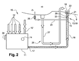
図2は、本発明によるドレイン装置10の第1実施形態を示し、ポンピングおよび排出手段と監視手段とはそれぞれ参照符号13および14によって示される。
FIG. 2 shows a first embodiment of the
ここに示された実施例では、ポンピングおよび排出手段13は、導管16によって収集器11の液体出口17に連結された入口15と、エンジン1の排出ノズル9の中へ通じる出口18とを備える。収集器11は、ライン12からのドレイン液を受け取り(概略が矢印によって示される)、これには好ましくは、液体が受け取られる収集器の内部空洞を通気する通気口12’が設けられる。
In the embodiment shown here, the pumping and discharge means 13 comprises an
この場合、ポンピングおよび排出手段13は、ドレイン液体が流れる第1ライン20が設けられた噴射ポンプエジェクタ19を備え、その一方(上流)端部は上述の入口15を形成し、その他方(下流)端部は上述の出口18を形成する。図1で概略が示されるように、前記出口18は、拡散器を下流に確定するようにその流れ断面内で絞り部を備えることが可能である。
In this case, the pumping and discharging means 13 comprises an injection pump ejector 19 provided with a
ポンピングおよび排出手段13は、加圧ガスを霧化する第2ライン21も備え、それはこの場合第1ライン20の内側に延在し、前記第2ライン21を出てゆく霧化ガスが、ライン20内を流れる液体に対してその出口18に向かって噴射ノズル9の中へ排出されることを強制するように設計される。この加圧ガスは上述の拡散器内で拡張することを目的とし、このことは、負の圧力を作り出し、ドレイン液体がはるか噴射ノズル9の中へ流れることを強制する。
The pumping and discharging means 13 also comprises a
このように、第2ライン21は第1ライン20の出口18の領域内に位置付けられた加圧ガス出口22を備える。第2ラインの入口23は、導管24によって、エンジン1から加圧ガスを抽気する手段(図示されず)に連結される。加圧ガスは、例えば平面P25またはP3の領域内で(平面P25は2つのインペラの間に位置付けられ、平面P3はこれらのインペラの下流に位置付けられる)、エンジンの圧縮機3から抽かれることが可能である。
Thus, the
ポンピングの作動と液体が噴射ノズル9の中へ排出される時間との両方を制御するために、導管24にフラップ弁25が設けられる。フラップ弁25は、このガスの圧力が所定の閾値以上になると開き、抽気された加圧ガスを導管の中へはるかエジェクタ19まで通らせることを目的としている。この場合、フラップ弁25は、抽気手段のガス出口を取り囲む着座に対して圧縮バネで付勢された可動球によって示される。このように、フラップ弁25は加圧ガスによって作動される。上述のガス圧力の閾値は、とりわけ上述の実施例ではバネのバネ定数に依存するが、好ましくはドレイン液体が排出される時間を正確に制御するために、特にエンジンが点火されるが否や前記排出が起こらないように、決定される。
A
この場合、収集器11を監視する手段14は単一のオーバーフロー部34によって示される。本発明によると、前記監視手段14は、収集器11によって受け取られる液体の流量がポンピング手段13(エジェクタ19)の送達量よりも大きくなると作動されるように設計される。このように、監視手段14は、異常な様態で液体が収集器11によって収集されているとそれを知らせること、特にエンジンの正常動作中の通常の量と比較して大き過ぎるドレイン液体の量を知らせることを可能にする。
In this case, the
収集される液の流量がポンピング手段13の送達量よりも大きいと、監視手段14は、視覚および/または電気警報であることができる信号を発するように設計されることが可能である。 When the flow rate of the collected liquid is greater than the delivered amount of the pumping means 13, the monitoring means 14 can be designed to emit a signal that can be a visual and / or electrical alarm.
ポンピングの送達量をエンジンの正常な作動、即ち出現する場合のある液体損失および漏れがエンジンの作動に影響を及ぼさない作動に対応する閾値に設定することによって、収集される液体の流量がポンピングの送達量よりも大きくなるが否や、ポンピング手段13が収集液体を排出する必要はもはやなくなる。収集器によって許容される場合、収集器11内の液体の高さは、エンジンの故障がある場合このように増大する。
By setting the pumping delivery rate to a threshold value that corresponds to normal operation of the engine, i.e., liquid loss and leakage that may appear does not affect engine operation, the collected fluid flow rate will be reduced. As soon as it is greater than the delivered amount, it is no longer necessary for the pumping means 13 to drain the collected liquid. If allowed by the collector, the height of the liquid in the
収集器11が、操作者が液体の高さを見ることが可能な窓を備える場合、そのように操作者に警告を発すること(視覚警報)を目的としたこの窓は、監視手段14に含まれる。
If the
変化形態では、または追加の特色として、特に、収集された液体の量が収集器11内の液体保管量よりも大きいとき、液体を収集器11から逃がすことを目的としたオーバーフロー部34を収集器11が備えることが可能である。警報手段の代わりまたはそれに加えて、エンジンの故障がある場合、操作者は、液体がオーバーフロー部34の高さを超過すると作り出されるドリップマークを見ることが可能であり、オーバーフロー部34はこのように他のタイプの視覚警報を形成する。オーバーフロー部34は、管によってエンジンデッキの排水口または補助的な回収容器に連結されることが可能である。
In a variation, or as an additional feature, the collector may include an
電気および視覚警報として、監視手段14は、収集器11内の液体の高さを検出して航空機のコックピットに向けられた信号を発することを目的としたセンサを備えることが可能である。その信号は、例えば警告灯によってパイロットに見られることが可能である。
As an electrical and visual alarm, the monitoring means 14 may comprise sensors intended to detect the height of the liquid in the
このように、監視手段14は、操作者または航空機パイロットに警告を発するのに充分迅速に、液体の大量の異常な漏れを検出することを可能にする。警報の作動は、エンジンの故障が発生していること、メンテナンス作業が実施されるべきであることを知らせる。 In this way, the monitoring means 14 makes it possible to detect a large amount of abnormal leakage of liquid quickly enough to alert the operator or aircraft pilot. The activation of the alarm informs that an engine failure has occurred and that maintenance work should be performed.
本発明の一部を形成するわけではないが、図2に部分図で示されるエンジンは、この場合には、燃焼室4で燃焼されていない燃料を収集し、前記燃料を導管27によって噴射ノズル9に向けて排出するのに使用される他のドレイン手段26を備え、その出口は噴射ノズルの中へ通じる。本発明によるドレイン装置10は、ポンピング手段も監視手段も設けられないこれらのドレイン手段26とは別である。
Although not forming part of the present invention, the engine shown in partial view in FIG. 2 collects unburned fuel in the
図3から図10は本発明の代替的実施形態を示し、それらの中で上記の要素は同じ参照符号で示される。 3 to 10 show alternative embodiments of the present invention, in which the above elements are designated with the same reference numerals.
図3の変化形態では、ポンピング手段13(エジェクタ19)は収集器11内に組み込まれる。第1ライン20は収集器11の液体出口17に直接取り付けられ、導管16の一方端部に連結され、その他方端部はノズル9の中へ通じる。エジェクタ19の第2ライン21は第1ライン20の内側に延在し、その入口23は、フラップ弁25が設けられることが可能な導管24によって、エンジン1から加圧ガスを抽気する手段に連結される。
In the variant of FIG. 3, the pumping means 13 (ejector 19) is integrated in the
図3のドレイン装置も同様に上記のタイプの監視手段14を備える。 The drain device of FIG. 3 also comprises monitoring means 14 of the type described above.
この装置は図2と同様に機能する。 This device functions similarly to FIG.
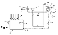
図4の実施形態では、ポンピング手段13はエジェクタ19を備え、その第1ライン20はノズルを形成するように第2ライン21の内側に取り付けられる。第1ライン20の入口は、導管16によって収集器11の液体出口17に連結される。第2ライン21の入口は導管24によって抽気手段に連結され、その出口は第1ライン20の出口の周りに延在し、噴射ジェット9の中へ通じる。
In the embodiment of FIG. 4, the pumping means 13 comprises an ejector 19, the
この場合、エジェクタ19は排出ノズルのように塗料吹付けガンの方式で機能する。これは、第1ライン20の出口18の周りで加圧ガスを放出することによって動作して、液体を収集器11から噴射ノズル9に向けて吹き付ける。
In this case, the ejector 19 functions like a paint spray gun like a discharge nozzle. This operates by releasing pressurized gas around the
加えて、エジェクタの第2ライン21を抽気手段に連結する導管24に、その流れ断面内で絞り部28が設けられる(図2のフラップ弁25の代わりに)。この絞り部28は、液体の排出を、エンジンが始動される際にそれが起こらないように遅らせることを可能にする。始動中、圧力はこのようにエジェクタの第2ライン21内で僅かに上昇し、所定の圧力閾値に対して超過が起こると液体は噴射ノズル9の中へ排出される。
In addition, the
ドレイン装置も同様に上述のタイプの監視手段14を備える。 The drain device likewise comprises monitoring means 14 of the type described above.
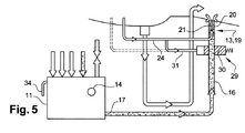
図5の代替的実施形態は、主に導管24にフラップ弁も絞り部も設けられないという点で図2の実施形態とは異なる。その代わりに、弁29、例えば滑り弁が、収集器11の出口17をエジェクタ19の第1ライン20の入口に連結する導管16上に取り付けられる。
The alternative embodiment of FIG. 5 differs from the embodiment of FIG. 2 primarily in that the
弁29は、導管16の一部位によって収集器11の出口17に連結される入口と、導管16の他の部位によってエジェクタ19の第1ライン20の入口に連結される出口とを備える。弁29は内部部材30をさらに備え、これは弁29の上述の出口および/または入口の閉鎖位置と、弁29の入口と出口が流体連結している位置との間を移動することが可能である。部材30はバネによって弁29の閉鎖位置へと偏らされる。この部材30の移動は加圧ガスによって制御され、この場合にはそれはエンジンから上述の抽気手段によって抽気された加圧ガスの一部分である。そのようにするために、抽気手段をエジェクタ19に連結する導管24は、部材が移動可能に取り付けられた弁29内の空洞に連結されるバイパス31を備えることが可能である。弁29は、抽気されたガスが所定の閾値以上になると開くことを目的とする。所定の閾値は、上述の実施例では特にバネのバネ定数に依存し、ドレイン液体が排出される時間を、特にエンジンが点火されるや否や前記排出が起こらないように精確に制御するように決定されることが好ましい。
The
代替方法として、図5の点線で示されるように、導管31は、弁の反対側のその端部によってエンジンの圧縮機から抽気する手段に連結されることが可能である。
Alternatively, as shown by the dotted line in FIG. 5, the
図6の代替的実施形態は、主に、導管24が、エンジンの圧縮機からでなく、エンジンからガスを除去するシステム(図示されず)から加圧ガスを抽気する手段に連結されるという点で、図2の実施形態とは異なる。このように、液体はエンジンからガスを除去するシステムによって噴射ノズル9の中へ排出される。
The alternative embodiment of FIG. 6 is primarily that the
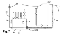
図7の代替的実施形態は、主に、エジェクタの第2ライン21を抽気手段に連結する導管24にその流れ断面内で絞り部28が設けられる(図3のフラップ弁25の代わりに)という点で、図3の実施形態とは異なる。この絞り部28は図4を参照して述べられた絞り部と同じ機能を有する。
In the alternative embodiment of FIG. 7, the
図8の代替的実施形態は、主に、エジェクタの第2ライン21を抽気手段に連結する導管24にその流れ断面内で絞り部28が設けられる(図2のフラップ弁25の代わりに)という点で、図2の実施形態とは異なる。この絞り部28は図4を参照して述べられた絞り部と同じ機能を有する。
In the alternative embodiment of FIG. 8, the
図9の代替的実施形態は、主に、エジェクタ19の第2ライン21を抽気手段に連結する導管24に電気制御弁32が設けられる(図3のフラップ弁25の代わりに)という点で、図3の実施形態とは異なる。この弁32は、例えば前記弁がエンジンコンピュータによって送信されたコマンドによって作動されると、抽気された加圧ガスを通過させるべく開くことを目的としている。
The alternative embodiment of FIG. 9 is mainly in that an
図10の代替的実施形態では、ドレイン装置のポンピング手段13は、導管16上に取り付けられた電気または機械ポンプ33を備え、その一方端部は収集器11の出口17に連結され、反対端部は噴射ノズル9の中へ通じる。作動されると、このポンプ33は液体を収集器11から噴射ノズル9へ搬送する。このポンプの送達量も、送達量の閾値を設定するように目盛り調整される。閾値を超えると監視装置がエンジンの異常な作動を知らせる。この変化形態は弁も、絞り部も、空気が抽気されることも必要としない。ドレイン装置は同様に上記のタイプの監視手段14を備える。
In the alternative embodiment of FIG. 10, the pumping means 13 of the drain device comprises an electric or mechanical pump 33 mounted on the
Claims (10)
Applications Claiming Priority (3)
| Application Number | Priority Date | Filing Date | Title |
|---|---|---|---|
| FR1363087 | 2013-12-19 | ||
| FR1363087A FR3015567B1 (en) | 2013-12-19 | 2013-12-19 | DEVICE FOR DRAINING FLUIDS FOR AN AIRCRAFT ENGINE |
| PCT/FR2014/053333 WO2015092243A1 (en) | 2013-12-19 | 2014-12-15 | Fluid-draining device for an aircraft engine |
Publications (2)
| Publication Number | Publication Date |
|---|---|
| JP2017503951A true JP2017503951A (en) | 2017-02-02 |
| JP2017503951A5 JP2017503951A5 (en) | 2018-01-18 |
Family
ID=50289992
Family Applications (1)
| Application Number | Title | Priority Date | Filing Date |
|---|---|---|---|
| JP2016539936A Pending JP2017503951A (en) | 2013-12-19 | 2014-12-15 | Liquid drain device for aircraft engines |
Country Status (10)
| Country | Link |
|---|---|
| US (1) | US10539077B2 (en) |
| EP (1) | EP3084187B1 (en) |
| JP (1) | JP2017503951A (en) |
| KR (1) | KR20160094990A (en) |
| CN (1) | CN105829681B (en) |
| CA (1) | CA2933531C (en) |
| FR (1) | FR3015567B1 (en) |
| PL (1) | PL3084187T3 (en) |
| RU (1) | RU2666719C1 (en) |
| WO (1) | WO2015092243A1 (en) |
Families Citing this family (10)
| Publication number | Priority date | Publication date | Assignee | Title |
|---|---|---|---|---|
| US11512811B2 (en) | 2016-07-12 | 2022-11-29 | Sikorsky Aircraft Corporation | System and method for detecting a lubricant-out condition in an aircraft gearbox |
| NO343014B1 (en) * | 2017-03-24 | 2018-10-01 | Karmoey Winch As | A pumping system and method |
| FR3082560B1 (en) * | 2018-06-14 | 2020-08-28 | Safran Aircraft Engines | ON-BOARD SYSTEM AND METHOD FOR DRAINING AN AIRCRAFT ENGINE |
| FR3082507B1 (en) * | 2018-06-14 | 2022-01-28 | Safran Aircraft Engines | DEVICE AND METHOD FOR DRAINING AND MONITORING DRAINED FLUID FROM AN AIRCRAFT ENGINE |
| FR3082508B1 (en) * | 2018-06-14 | 2021-12-03 | Safran Aircraft Engines | ON-BOARD DRAINAGE TANK OF AN AIRCRAFT ENGINE |
| CN109319159B (en) * | 2018-11-28 | 2024-03-15 | 江西荣力航空工业有限公司 | Residual oil collecting and discharging device of helicopter engine |
| CN111980803B (en) * | 2019-05-24 | 2022-03-15 | 中国航发商用航空发动机有限责任公司 | Aircraft engine |
| EP3798113B1 (en) * | 2019-09-30 | 2023-03-29 | Rohr, Inc. | Fluid drainage system for an aircraft propulsion system |
| FR3114128B1 (en) * | 2020-09-14 | 2022-11-04 | Airbus Helicopters | Drainage system of an aircraft combustion engine and associated aircraft |
| FR3137408A1 (en) | 2022-06-29 | 2024-01-05 | Safran Helicopter Engines | Drained assembly of an aircraft turbomachine |
Citations (7)
| Publication number | Priority date | Publication date | Assignee | Title |
|---|---|---|---|---|
| US3556444A (en) * | 1968-02-02 | 1971-01-19 | Entwicklungsring Sued Gmbh | Apparatus for the disposal of aircraft engine leakage fluids |
| JPS4851112A (en) * | 1971-10-28 | 1973-07-18 | ||
| JPS61123787A (en) * | 1984-11-16 | 1986-06-11 | Mitsubishi Heavy Ind Ltd | Abnormality monitoring device for hydraulic equipment |
| JPH0796897A (en) * | 1993-09-29 | 1995-04-11 | Kokusai Electric Co Ltd | Flight-data recorder incorporating alarm function |
| JP2006242083A (en) * | 2005-03-02 | 2006-09-14 | Toshiba Corp | Reheat system for power generation plant |
| US20120287960A1 (en) * | 2011-05-12 | 2012-11-15 | Thompson William W | Leak detection apparatus for aircraft bleed air systems |
| US20130201023A1 (en) * | 2012-02-08 | 2013-08-08 | Eurocopter | Drainage circuit for draining liquid coming from a power plant of a rotorcraft, the circuit incorporating an appliance for monitoring an excessive flow of the liquid |
Family Cites Families (11)
| Publication number | Priority date | Publication date | Assignee | Title |
|---|---|---|---|---|
| US3623053A (en) * | 1969-10-23 | 1971-11-23 | Gen Electric | Leak-detecting apparatus |
| US5285636A (en) * | 1992-10-28 | 1994-02-15 | General Electric Company | Diagnostic drain mast for a gas turbine engine |
| FR2726603B1 (en) * | 1994-11-09 | 1996-12-13 | Snecma | DEVICE FOR ACTIVE CONTROL OF THE COMBUSTION AND DECOKEFACTION INSTABILITIES OF A FUEL INJECTOR |
| IT1318110B1 (en) * | 2000-07-03 | 2003-07-23 | Nuovo Pignone Spa | DISCHARGE AND REFRIGERATION SYSTEM FOR THE CUSHIONS OF AN AGAS TURBINE |
| US6578361B1 (en) * | 2001-08-30 | 2003-06-17 | General Electric Co. | Methods and apparatus for determining engine cavity leakage |
| US6571562B2 (en) * | 2001-10-08 | 2003-06-03 | Honeywell International Inc. | Witness drain valve |
| FR2913250B1 (en) * | 2007-03-02 | 2009-05-29 | Turbomeca Sa | METHOD FOR STARTING A GAS TURBINE HELICOPTER ENGINE, FUEL SUPPLY CIRCUIT FOR SUCH AN ENGINE, AND MOTOR HAVING SUCH A CIRCUIT |
| EP2052792A3 (en) * | 2007-10-09 | 2011-06-22 | Gas Turbine Efficiency Sweden AB | Drain valve, washing system and sensing of rinse and wash completion |
| JP5571805B2 (en) * | 2010-02-17 | 2014-08-13 | フスクバルナ アクティエボラーグ | Power tools |
| US20130327059A1 (en) * | 2011-03-01 | 2013-12-12 | Short Brothers Plc | Draining device |
| US20150000749A1 (en) * | 2013-06-27 | 2015-01-01 | Mag Aerospace Industries, Llc | Water management system |
-
2013
- 2013-12-19 FR FR1363087A patent/FR3015567B1/en active Active
-
2014
- 2014-12-15 JP JP2016539936A patent/JP2017503951A/en active Pending
- 2014-12-15 KR KR1020167016369A patent/KR20160094990A/en not_active Application Discontinuation
- 2014-12-15 WO PCT/FR2014/053333 patent/WO2015092243A1/en active Application Filing
- 2014-12-15 CA CA2933531A patent/CA2933531C/en active Active
- 2014-12-15 EP EP14827837.7A patent/EP3084187B1/en active Active
- 2014-12-15 PL PL14827837T patent/PL3084187T3/en unknown
- 2014-12-15 RU RU2016125764A patent/RU2666719C1/en active
- 2014-12-15 CN CN201480068556.2A patent/CN105829681B/en active Active
- 2014-12-15 US US15/104,462 patent/US10539077B2/en active Active
Patent Citations (7)
| Publication number | Priority date | Publication date | Assignee | Title |
|---|---|---|---|---|
| US3556444A (en) * | 1968-02-02 | 1971-01-19 | Entwicklungsring Sued Gmbh | Apparatus for the disposal of aircraft engine leakage fluids |
| JPS4851112A (en) * | 1971-10-28 | 1973-07-18 | ||
| JPS61123787A (en) * | 1984-11-16 | 1986-06-11 | Mitsubishi Heavy Ind Ltd | Abnormality monitoring device for hydraulic equipment |
| JPH0796897A (en) * | 1993-09-29 | 1995-04-11 | Kokusai Electric Co Ltd | Flight-data recorder incorporating alarm function |
| JP2006242083A (en) * | 2005-03-02 | 2006-09-14 | Toshiba Corp | Reheat system for power generation plant |
| US20120287960A1 (en) * | 2011-05-12 | 2012-11-15 | Thompson William W | Leak detection apparatus for aircraft bleed air systems |
| US20130201023A1 (en) * | 2012-02-08 | 2013-08-08 | Eurocopter | Drainage circuit for draining liquid coming from a power plant of a rotorcraft, the circuit incorporating an appliance for monitoring an excessive flow of the liquid |
Also Published As
| Publication number | Publication date |
|---|---|
| EP3084187B1 (en) | 2020-02-26 |
| CA2933531A1 (en) | 2015-06-25 |
| WO2015092243A1 (en) | 2015-06-25 |
| CN105829681A (en) | 2016-08-03 |
| RU2666719C1 (en) | 2018-09-11 |
| RU2016125764A (en) | 2018-01-24 |
| US10539077B2 (en) | 2020-01-21 |
| PL3084187T3 (en) | 2020-06-29 |
| EP3084187A1 (en) | 2016-10-26 |
| KR20160094990A (en) | 2016-08-10 |
| FR3015567B1 (en) | 2015-12-25 |
| FR3015567A1 (en) | 2015-06-26 |
| CN105829681B (en) | 2018-07-10 |
| US20160312707A1 (en) | 2016-10-27 |
| CA2933531C (en) | 2022-03-22 |
Similar Documents
| Publication | Publication Date | Title |
|---|---|---|
| JP2017503951A (en) | Liquid drain device for aircraft engines | |
| US10415692B2 (en) | Emergency lubrication device of simplified architecture for a power transmission main gearbox of an aircraft | |
| CN109661504B (en) | Control system for gas turbine engine | |
| JP6408812B2 (en) | Anti-icing system for gas turbine | |
| CN110735739B (en) | Internal combustion engine with a venturi nozzle arranged in a fluid-conducting component | |
| EP3141724B1 (en) | Detection of high stage valve leakage by pressure lockup | |
| JP2005024093A (en) | Device and method for lubrication | |
| GB2266964A (en) | Device for detecting a fuel leak in an oil-fuel heat exchanger mounted in an engine lubrication circuit. | |
| EP2762408B1 (en) | Aircraft engine nacelle with bi-directional ventilation system and related methods | |
| CN103389191B (en) | By the device of the transmission case sealing of suction monitoring rotocraft | |
| FR3052747A1 (en) | METHOD FOR MONITORING THE ENGINES OF AN AIRCRAFT | |
| JP2008208832A (en) | Device and method for standby lubrication of engine | |
| EP2971702B1 (en) | Bleed valve assembly | |
| US20220026020A1 (en) | Method for monitoring a fluid system lubricating a mechanical system | |
| US10513988B2 (en) | Fuel circuit comprising means for controlling a pump | |
| US20210052999A1 (en) | Method and system for monitoring a fluid system configured to operate with a filter | |
| US20130247538A1 (en) | Oil discharge device and turbomachine comprising such a device | |
| US11585272B2 (en) | System and method for detection of excessive flow in a fluid system | |
| CA3106652A1 (en) | Aircraft pneumatic system | |
| KR20170061132A (en) | Device and method for testing the integrity of a helicopter turbine engine rapid restart system | |
| US10487749B2 (en) | Method for detecting a fault, fault detection system and gas turbine engine | |
| EP3798113B1 (en) | Fluid drainage system for an aircraft propulsion system | |
| CN105863846A (en) | Method for removing air plug of lubricating oil pump of engine | |
| US10054002B2 (en) | Method for assisting with the detection of damage to a turbojet duct | |
| Wang et al. | Estimation of APU Compartment Drainage Capability |
Legal Events
| Date | Code | Title | Description |
|---|---|---|---|
| A521 | Request for written amendment filed |
Free format text: JAPANESE INTERMEDIATE CODE: A523 Effective date: 20171201 |
|
| A621 | Written request for application examination |
Free format text: JAPANESE INTERMEDIATE CODE: A621 Effective date: 20171201 |
|
| A131 | Notification of reasons for refusal |
Free format text: JAPANESE INTERMEDIATE CODE: A131 Effective date: 20180911 |
|
| A977 | Report on retrieval |
Free format text: JAPANESE INTERMEDIATE CODE: A971007 Effective date: 20180913 |
|
| A521 | Request for written amendment filed |
Free format text: JAPANESE INTERMEDIATE CODE: A523 Effective date: 20181114 |
|
| A131 | Notification of reasons for refusal |
Free format text: JAPANESE INTERMEDIATE CODE: A131 Effective date: 20190416 |
|
| A601 | Written request for extension of time |
Free format text: JAPANESE INTERMEDIATE CODE: A601 Effective date: 20190710 |
|
| A521 | Request for written amendment filed |
Free format text: JAPANESE INTERMEDIATE CODE: A523 Effective date: 20190911 |
|
| A02 | Decision of refusal |
Free format text: JAPANESE INTERMEDIATE CODE: A02 Effective date: 20200212 |
|
| C60 | Trial request (containing other claim documents, opposition documents) |
Free format text: JAPANESE INTERMEDIATE CODE: C60 Effective date: 20200609 |
|
| C22 | Notice of designation (change) of administrative judge |
Free format text: JAPANESE INTERMEDIATE CODE: C22 Effective date: 20201027 |
|
| C13 | Notice of reasons for refusal |
Free format text: JAPANESE INTERMEDIATE CODE: C13 Effective date: 20201222 |
|
| A601 | Written request for extension of time |
Free format text: JAPANESE INTERMEDIATE CODE: A601 Effective date: 20210318 |
|
| C22 | Notice of designation (change) of administrative judge |
Free format text: JAPANESE INTERMEDIATE CODE: C22 Effective date: 20210413 |
|
| C22 | Notice of designation (change) of administrative judge |
Free format text: JAPANESE INTERMEDIATE CODE: C22 Effective date: 20210810 |
|
| C23 | Notice of termination of proceedings |
Free format text: JAPANESE INTERMEDIATE CODE: C23 Effective date: 20210824 |
|
| C03 | Trial/appeal decision taken |
Free format text: JAPANESE INTERMEDIATE CODE: C03 Effective date: 20210928 |
|
| C30A | Notification sent |
Free format text: JAPANESE INTERMEDIATE CODE: C3012 Effective date: 20210928 |