JP2017502193A - Predicting maintenance work to be done on aircraft engines - Google Patents
Predicting maintenance work to be done on aircraft engines Download PDFInfo
- Publication number
- JP2017502193A JP2017502193A JP2016536978A JP2016536978A JP2017502193A JP 2017502193 A JP2017502193 A JP 2017502193A JP 2016536978 A JP2016536978 A JP 2016536978A JP 2016536978 A JP2016536978 A JP 2016536978A JP 2017502193 A JP2017502193 A JP 2017502193A
- Authority
- JP
- Japan
- Prior art keywords
- damage
- maintenance
- mission
- consumption
- missions
- Prior art date
- Legal status (The legal status is an assumption and is not a legal conclusion. Google has not performed a legal analysis and makes no representation as to the accuracy of the status listed.)
- Granted
Links
Images


Classifications
-
- G—PHYSICS
- G05—CONTROLLING; REGULATING
- G05B—CONTROL OR REGULATING SYSTEMS IN GENERAL; FUNCTIONAL ELEMENTS OF SUCH SYSTEMS; MONITORING OR TESTING ARRANGEMENTS FOR SUCH SYSTEMS OR ELEMENTS
- G05B23/00—Testing or monitoring of control systems or parts thereof
- G05B23/02—Electric testing or monitoring
- G05B23/0205—Electric testing or monitoring by means of a monitoring system capable of detecting and responding to faults
- G05B23/0259—Electric testing or monitoring by means of a monitoring system capable of detecting and responding to faults characterized by the response to fault detection
- G05B23/0283—Predictive maintenance, e.g. involving the monitoring of a system and, based on the monitoring results, taking decisions on the maintenance schedule of the monitored system; Estimating remaining useful life [RUL]
-
- G—PHYSICS
- G06—COMPUTING; CALCULATING OR COUNTING
- G06Q—INFORMATION AND COMMUNICATION TECHNOLOGY [ICT] SPECIALLY ADAPTED FOR ADMINISTRATIVE, COMMERCIAL, FINANCIAL, MANAGERIAL OR SUPERVISORY PURPOSES; SYSTEMS OR METHODS SPECIALLY ADAPTED FOR ADMINISTRATIVE, COMMERCIAL, FINANCIAL, MANAGERIAL OR SUPERVISORY PURPOSES, NOT OTHERWISE PROVIDED FOR
- G06Q10/00—Administration; Management
- G06Q10/20—Administration of product repair or maintenance
Landscapes
- Engineering & Computer Science (AREA)
- Business, Economics & Management (AREA)
- Physics & Mathematics (AREA)
- General Physics & Mathematics (AREA)
- Human Resources & Organizations (AREA)
- Automation & Control Theory (AREA)
- Marketing (AREA)
- Entrepreneurship & Innovation (AREA)
- Economics (AREA)
- Operations Research (AREA)
- Quality & Reliability (AREA)
- Strategic Management (AREA)
- Tourism & Hospitality (AREA)
- General Business, Economics & Management (AREA)
- Theoretical Computer Science (AREA)
- Management, Administration, Business Operations System, And Electronic Commerce (AREA)
- Testing Of Engines (AREA)
- Testing Of Devices, Machine Parts, Or Other Structures Thereof (AREA)
Abstract
本発明は、複数のダメージカウンタにより監視される複数のコンポーネントを備えた航空機エンジンに実行されるメンテナンス作業を予測するための方法及びシステムに関連している。前記複数のダメージカウンタの各々は、対応するダメージ上限により制限される。当該システムは、経験ミッションを含む学習データベース(31)から一連のシミュレーションミッションを繰り返し抽出することにより、前記ダメージカウンタ(C1〜Cm)の消費をシミュレートするように構成された処理手段(7)と、現在のシミュレーションミッションに関連する少なくとも1つのダメージカウンタが前記ダメージカウンタに関連するダメージ上限に達するまで、前記複数のダメージカウンタの各々の累積消費を繰り返しごとに測定するように構成された処理手段(7)と、前記現在のシミュレーションミッションにメンテナンス戦略を適用することで、前記航空機エンジンに対して実行されるメンテナンス作業を示すメンテナンスインジケータを決定するように構成された処理手段(7)と、を備える。The present invention relates to a method and system for predicting maintenance work performed on an aircraft engine with multiple components monitored by multiple damage counters. Each of the plurality of damage counters is limited by a corresponding damage upper limit. The system includes processing means (7) configured to simulate consumption of the damage counters (C1 to Cm) by repeatedly extracting a series of simulation missions from a learning database (31) including experience missions. A processing means configured to measure each cumulative consumption of each of the plurality of damage counters repeatedly until at least one damage counter associated with the current simulation mission reaches a damage limit associated with the damage counter; 7) and processing means (7) configured to determine a maintenance indicator indicative of a maintenance operation performed on the aircraft engine by applying a maintenance strategy to the current simulation mission. .
Description
本発明は、航空機エンジンのメンテナンスの分野に関する。詳細には、本発明は、航空機エンジンに行われるべきメンテナンス作業を予測するための方法及びシステムに関する。 The present invention relates to the field of aircraft engine maintenance. In particular, the present invention relates to a method and system for predicting maintenance work to be performed on an aircraft engine.
航空機エンジンに行われるメンテナンス作業の予測は、エンジンの様々な要素の推定される損傷(ダメージ)又は磨耗の関数として決定される。 The prediction of maintenance work performed on an aircraft engine is determined as a function of estimated damage or wear of various elements of the engine.
しかし、1つの飛行任務と別の飛行任務とで変化し得る条件下で(例えば軍用機の場合)航空機エンジンを使用すると、エンジンへのダメージを直接予測することは不可能である。この場合、評価は、飛行パラメータの記録から各飛行任務に関して算出されたダメージカウンタに基づいて行われる。 However, if an aircraft engine is used under conditions that can vary from one flight mission to another (eg in the case of military aircraft), it is impossible to directly predict damage to the engine. In this case, the evaluation is performed based on a damage counter calculated for each flight mission from the flight parameter record.
航空機エンジンは、様々なコンポーネントを各々が含む複数のモジュールから構成されている。各コンポーネントは、監視されるべき複数のゾーン又は要素を含み得、これらがコンポーネントの寿命を左右する。本明細書以下、簡略化のために、単にコンポーネントに関して論じる。ダメージカウンタが各コンポーネントに関連付けられ、コンポーネントにより消費された実際のサイクルの数をカウントする。また、各々のダメージカウンタは、少なくとも1つのダメージ上限にも関連付けられている。1以上の上限に達したときに、様々なメンテナンスアクションをなし得る。これらのメンテナンスアクションはメンテナンスプランに記載されており、取り外しをしない検査とは異なり、損傷部品を交換することであり、取り外しを必要とする検査を含む。メンテナンス管理作業の目的は、部品又はコンポーネントの動作可能使用期間を最大限引き延ばすようにジャストインタイムのメンテナンス作業を行うことである。 Aircraft engines are composed of a plurality of modules, each containing various components. Each component can include multiple zones or elements to be monitored, which affect the lifetime of the component. Hereinafter, for simplicity, only the components will be discussed. A damage counter is associated with each component and counts the actual number of cycles consumed by the component. Each damage counter is also associated with at least one damage upper limit. Various maintenance actions can be taken when one or more limits are reached. These maintenance actions are described in the maintenance plan and, unlike inspections that do not remove, replace damaged parts and include inspections that require removal. The purpose of the maintenance management work is to perform a just-in-time maintenance work so as to maximize the operable use period of the part or component.
しかし、ダメージカウンタの消費、及び、これらの消費速度は、1つのミッションと別のミッションとで、特にミッションタイプにより著しく異なる。従って、ダメージカウンタがそれらの上限に、異なる速度で、従って、異なる飛行で達する場合がある。そして、ダメージカウンタにより定義されるメンテナンスが、非常に頻繁な取り外しを必要とする場合がある。ダメージカウンタがそれらの上限に達する時点が異なり得ることが、しばしば頻繁な取り外しを生じる。これらの様々な取り外しが、航空機の規則的な利用可能性に影響する場合がある。 However, the consumption of the damage counter and the consumption speed thereof are significantly different between one mission and another mission, particularly depending on the mission type. Thus, damage counters may reach their upper limit at different speeds and, therefore, different flights. And the maintenance defined by the damage counter may require very frequent removal. It can often result in frequent removals when the damage counter can reach their upper limit. These various removals can affect the regular availability of the aircraft.
従って、本発明の目的は、全ての安全要求条件及び制約を尊重しつつ、航空機の利用可能性を向上させるために航空機エンジンへのメンテナンス作業を最適化することである。 Accordingly, it is an object of the present invention to optimize maintenance operations on aircraft engines to improve aircraft availability while respecting all safety requirements and constraints.
本発明は、複数のダメージカウンタにより監視される複数のコンポーネントを備えた航空機エンジン又は航空機エンジンの一部に行われるべきメンテナンス作業を予測する方法に関する。前記複数のダメージカウンタの各々は、対応するダメージ上限により制限されている。この方法は、
学習データベースから一連のシミュレーションミッションを繰り返し抽出することにより、前記ダメージカウンタの消費をシミュレートするステップと、
現在のシミュレーションミッションに関連する少なくとも1つのダメージカウンタが前記ダメージカウンタに関連するダメージ上限により制限された所定の値に達するまで、前記複数のダメージカウンタの各々の累積消費を繰り返しごとに測定するステップと、
前記現在のシミュレーションミッションにメンテナンス戦略を適用することで、前記航空機エンジンに対して計画されるメンテナンス作業を示すメンテナンスインジケータを決定するステップと、
を含む。
The present invention relates to a method for predicting maintenance work to be performed on an aircraft engine or part of an aircraft engine with a plurality of components monitored by a plurality of damage counters. Each of the plurality of damage counters is limited by a corresponding damage upper limit. This method
Simulating consumption of the damage counter by repeatedly extracting a series of simulation missions from a learning database;
Measuring the cumulative consumption of each of the plurality of damage counters repeatedly until at least one damage counter associated with a current simulation mission reaches a predetermined value limited by a damage limit associated with the damage counter; ,
Determining a maintenance indicator indicative of a maintenance operation planned for the aircraft engine by applying a maintenance strategy to the current simulation mission;
including.
センサの消費を一連のミッションの単純な抽出によりシミュレートすることにより、メンテナンスアクションの回数及びタイプを、実装されたメンテナンス戦略に従って予測できる。メンテナンス戦略は、前記ダメージ上限に関連する所定の値により定義されている。このシミュレーション原理は、計算ステップのための非常に高い融通性を、低コストで、また、統計学の特別な知識を必要とせずに可能にする。 By simulating sensor consumption by simple extraction of a series of missions, the number and type of maintenance actions can be predicted according to the implemented maintenance strategy. The maintenance strategy is defined by a predetermined value related to the damage upper limit. This simulation principle allows very high flexibility for the computational steps at low cost and without the need for special knowledge of statistics.
有利には、前記方法は、
現在の戦略の適用ごとに、当該現在の戦略に関連するコストインジケータと有効性インジケータの決定と、前記コストインジケータ及び有効性インジケータの関数としての妥協インジケータの決定とを含む、一連の様々なメンテナンス戦略を適用するステップと、
様々な戦略のための妥協インジケータを比較して最適なメンテナンス戦略を選択するステップと、を含む。
Advantageously, the method comprises
For each application of the current strategy, a series of different maintenance strategies, including the determination of cost and validity indicators associated with the current strategy, and the determination of compromise indicators as a function of the cost and effectiveness indicators. Applying steps,
Comparing compromise indicators for various strategies and selecting an optimal maintenance strategy.
これは、ダメージカウンタの可変性を考慮すること、及び、適用されるべき最良の戦略を効率的に見出すことにより、メンテナンス戦略の良好な利用を可能にする。 This allows for good utilization of the maintenance strategy by taking into account the variability of the damage counter and efficiently finding the best strategy to be applied.
第1の実施形態によれば、メンテナンス戦略の適用は、
各ダメージカウンタの前記累積消費を決められた回数の飛行まで推定するステップと、
ダメージ上限に達したダメージカウンタに関連するメンテナンス作業をグループ化するステップと、を含む。
According to the first embodiment, the application of the maintenance strategy is
Estimating the cumulative consumption of each damage counter up to a predetermined number of flights;
Grouping maintenance operations related to damage counters that have reached the damage limit.
メンテナンス作業のグループ化は、エンジン有効性向上の手段をもたらす。例えば、メンテナンス作業のグループ化と同時に、次の50回又は100回の飛行中にトリガーされるアクションの予測により2000回飛行のホライズンをシミュレートできる。 Maintenance work grouping provides a means of improving engine effectiveness. For example, a 2000 flight horizon can be simulated by predicting actions triggered during the next 50 or 100 flights simultaneously with the grouping of maintenance operations.
第2の実施形態によれば、メンテナンス戦略の適用は、
前記現在のシミュレーションミッションのダメージカウンタの消費を、中間閾値又はダメージ上限より下の上限と比較するステップと、
前記中間上限に達したダメージカウンタに関連するメンテナンス作業をグループ化するステップと、を含む。
According to the second embodiment, the application of the maintenance strategy is
Comparing the consumption of the current simulation mission damage counter with an intermediate threshold or an upper limit below the damage upper limit;
Grouping maintenance work related to the damage counter that has reached the intermediate upper limit.
有利には、前記方法は、
前記シミュレートされたダメージカウンタの消費を複数回繰り返すことで、各メンテナンスインジケータに関連する一連の消費値を決定するステップと、
各メンテナンスインジケータに関連する前記消費値の平均を算出するステップと、
を含む。
Advantageously, the method comprises
Determining a series of consumption values associated with each maintenance indicator by repeating the consumption of the simulated damage counter multiple times;
Calculating an average of the consumption values associated with each maintenance indicator;
including.
これによれば、メンテナンス作業をより現実的に予測し、且つ統計的情報を得る手段を提供する。 According to this, a means for predicting maintenance work more realistically and obtaining statistical information is provided.
前記学習データベースは、
一連の経験ミッションと、前記経験ミッションの各々に関連するポテンシャルセンサの消費と、
ポテンシャルセンサに関連するダメージ上限と、対応するメンテナンスアクションを含む所定のメンテナンスプランと、
を含む。
The learning database is
A series of experience missions and the consumption of potential sensors associated with each of the experience missions;
A predetermined maintenance plan that includes the damage limit associated with the potential sensor and the corresponding maintenance action;
including.
有利には、前記学習データベースは、ミッションインジケータをさらに含み、
前記ミッションインジケータは、ミッション毎の重大性インジケータと、ミッション毎の飛行期間インジケータと、ミッションタイプインジケータとを含むことを特徴とする、請求項6に
Advantageously, the learning database further comprises a mission indicator;
7. The mission indicator of claim 6, wherein the mission indicator includes a mission criticality indicator, a mission duration indicator, and a mission type indicator.
これは、データベースを充実させ、また、ミッションを、重大性、タイプ又は期間の関数として分類できる。こうして、ミッションは、ランダムにより現実的に行われるように関連的に分類される。 This enriches the database and also allows missions to be classified as a function of severity, type or duration. In this way, missions are categorized in relation to be performed more realistically at random.
有利には、前記一連のシミュレーションミッションは、経験ミッションのサブセットからランダムに抽出される。 Advantageously, the series of simulation missions is randomly extracted from a subset of experience missions.
この結果、前記シミュレーションが、航空機ベース、フリート又は特定のミッションタイプに特異的に行われうる。こうして、メンテナンスプランが航空機の利用方法に適合可能となる。 As a result, the simulation can be performed specifically for aircraft-based, fleet or specific mission types. In this way, the maintenance plan can be adapted to the method of using the aircraft.
有利には、前記方法はデータベースの更新を含む。 Advantageously, the method comprises a database update.
これは、将来の及び乗客に応じた適合ミッションを代表するデータベースを有する手段を提供する。 This provides a means of having a database representative of future and passenger-specific adaptation missions.
また、本発明は、上記の特徴に従うメンテナンス作業予測方法を各航空機エンジンに適用することにより航空機エンジンフリートに用いられるメンテナンス予測ツールも対象とする。 The present invention is also directed to a maintenance prediction tool used for an aircraft engine fleet by applying the maintenance operation prediction method according to the above-described feature to each aircraft engine.
また、本発明は、複数のダメージカウンタにより監視される複数のコンポーネントを備えた航空機エンジンに行われるべきメンテナンス作業を予測するシステムである。各ダメージカウンタは、対応するダメージ上限により制限され、
前記システムは、
経験ミッションを含む学習データベースから一連のシミュレーションミッションを繰り返し抽出することにより、前記ダメージカウンタの消費をシミュレートするように構成された処理手段と、
現在のシミュレーションミッションに関連する少なくとも1つのダメージカウンタが前記ダメージカウンタに関連するダメージ上限に達するまで、前記複数のダメージカウンタの各々の累積消費を繰り返しごとに測定するように構成された処理手段と、
前記現在のシミュレーションミッションにメンテナンス戦略を適用することで、前記航空機エンジンに対して実行されるメンテナンス作業を示すメンテナンスインジケータを決定するように構成された処理手段と、
を備える。
The present invention is also a system for predicting a maintenance operation to be performed on an aircraft engine having a plurality of components monitored by a plurality of damage counters. Each damage counter is limited by the corresponding damage limit,
The system
Processing means configured to simulate consumption of the damage counter by repeatedly extracting a series of simulation missions from a learning database including experience missions;
Processing means configured to repeatedly measure the cumulative consumption of each of the plurality of damage counters until at least one damage counter associated with a current simulation mission reaches a damage limit associated with the damage counter;
Processing means configured to determine a maintenance indicator indicative of a maintenance operation performed on the aircraft engine by applying a maintenance strategy to the current simulation mission;
Is provided.
本発明による装置及び方法のその他の具体的な特徴及び利点は、情報として提供されているが限定的ではない以下の説明を、添付図面を参照しつつ読むことで明らかになろう。 Other specific features and advantages of the apparatus and method according to the present invention will become apparent upon reading the following description, given by way of information but not limitation, with reference to the accompanying drawings, in which:
本発明の概略的原理は、航空機エンジンのダメージカウンタの消費を、ミッションデータベースから開始して予測すること、及び、この予測を利用して、前記エンジンのエンジン有効性及びメンテナンスコストを最適化するためにメンテナンス戦略の適用を最適化することである。 The general principle of the present invention is to predict the consumption of aircraft engine damage counters starting from a mission database and to use this prediction to optimize engine efficiency and maintenance costs of the engine. To optimize the application of maintenance strategies.
図1は、本発明による、航空機エンジンに行われるべきメンテナンス作業を予測するためのシステムを概略的に示す。 FIG. 1 schematically illustrates a system for predicting maintenance work to be performed on an aircraft engine according to the present invention.
有利には、予測システム1は、地上ステーションでインストールされ、コンピュータシステム3を含む。コンピュータシステム3は、通常、入力手段5と、処理手段7と、記憶手段9と、出力手段11とを含む。記憶手段9は、本発明に係る予測方法の実行に適合されたコード命令を含むコンピュータプログラムを含み得ることに留意されたい。このコンピュータプログラムは、記憶手段9並びに入力手段5及び出力手段11に関連した処理手段7により実行され得る。
Advantageously, the
各飛行任務に関し、航空機13は、その搭載コンピュータ15に飛行パラメータを収集し、記録する。これらのデータは、定期的に(例えば、各飛行任務後に)ダウンロードされて、予測システム1により読み出され得る。これらのデータの幾つかが地上ステーションにリアルタイムで送信され得ることが理解されよう。
For each flight mission, the
予測システム1により読み出されたデータは、ダメージカウンタ17の消費を測定するために(すなわち、モジュールに生じた又はモジュールにより消費された真のサイクル数をカウントするために)使用されることで、航空機エンジンの様々なモジュールの磨耗又は損傷が推定される。
The data read by the
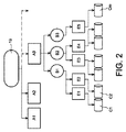
図2は、航空機エンジン用のダメージカウンタの構造を概略的に示す。 FIG. 2 schematically shows the structure of a damage counter for an aircraft engine.
航空機エンジン19は、モジュールのセットA1,A2,A3から構成され、各モジュールが、異なるコンポーネントB1,B2,B3を含む。各コンポーネントは、コンポーネントの寿命を測定するために使用できる複数のゾーン又は要素E1〜E5を含み得る。そして、少なくとも1つのダメージカウンタC1〜Cmが各要素E1〜E5に関連付けられて、この要素により消費されるサイクルの実数をカウントする。各ダメージカウンタの消費は、ダメージカウンタにより監視されているコンポーネントの、寿命(故障前)を特定する少なくとも1つのダメージ上限により制限されている。
The
そして、1又は複数のダメージ上限に達したとき、テーブル又はメンテナンスプラン(図4Bを参照)に記載されているメンテナンスアクションが想定されなければならない。 And when one or more damage upper limits are reached, the maintenance actions described in the table or maintenance plan (see FIG. 4B) must be assumed.
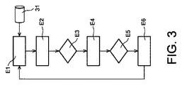
図3は、本発明に係る航空機エンジンへのメンテナンス作業を予測する方法を概略的示すフローチャートである。 FIG. 3 is a flow chart schematically illustrating a method for predicting maintenance work on an aircraft engine according to the present invention.
ステップE1において、処理手段7は、ダメージカウンタC1〜Cmの消費をシミュレートするように構成され、これは、一連のシミュレーションミッションを学習データベース31(例えば、記憶手段9に収容されている)から繰り返し抽出することにより行われる。学習データベース31は、一連の経験ミッションと、所定のメンテナンスプランを収容している。経験ミッションは、実際の飛行中に収集されたデータを含み、作業フィードバックを提供する。
In step E1, the processing means 7 is configured to simulate the consumption of the damage counters C1 to Cm, which repeats a series of simulation missions from the learning database 31 (for example, stored in the storage means 9). This is done by extracting. The
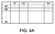
図4Aは、一連の経験ミッションと、関連するポテンシャルセンサとを含むテーブルを概略的に示す。 FIG. 4A schematically shows a table containing a series of experience missions and associated potential sensors.
第1の縦列は、様々なミッションM1〜Mnのためのコード又は番号を含む。その他の縦列は、エンジンの様々な要素に関連した様々なダメージカウンタC1〜Cmを示す。また、各ミッション中の各カウンタの消費を示す。各カウンタにより示されるサイクル又は消費の数値は、例えば、エンジンの対応するコンポーネントの磨耗又は損傷の測定値であり得る。 The first column contains codes or numbers for the various missions M1-Mn. The other columns show various damage counters C1-Cm associated with various elements of the engine. It also shows the consumption of each counter during each mission. The number of cycles or consumption indicated by each counter can be, for example, a measure of wear or damage to the corresponding component of the engine.
図4Bは、航空機エンジンのメンテナンスプランを記載したテーブルを概略的に示す。
である。
FIG. 4B schematically shows a table describing an aircraft engine maintenance plan.
It is.
第1の縦列は、エンジンの一連のモジュールA1〜Anを示す。各モジュールの様々なコンポーネントB1〜B3は、第2の縦列に示されている。第3の縦列は、各コンポーネントの様々な場所又は様々な要素E1〜E5を示す。第4の縦列は、エンジンの様々な要素に関連するダメージカウンタC1〜Cmを示す。第5の縦列は、様々なダメージカウンタC1〜Cmに関連するダメージ上限S1〜Smを示し、第6の縦列は、交換される前に複数回検査され得る要素の検査間の間隔I1〜Imを示すであろう。最後に、第7の縦列は、ダメージ上限に達したときに各要素又はコンポーネントに行われるべきメンテナンス作業OP1〜OPmを示す。 The first column shows a series of modules A1-An of the engine. The various components B1-B3 of each module are shown in the second column. The third column shows various locations or various elements E1-E5 of each component. The fourth column shows damage counters C1-Cm associated with various elements of the engine. The fifth column shows the damage limits S1-Sm associated with the various damage counters C1-Cm, and the sixth column shows the intervals I1-Im between the inspections of the elements that can be inspected multiple times before being replaced. Will show. Finally, the seventh column shows maintenance operations OP1 to OPm to be performed on each element or component when the damage upper limit is reached.
有利には、学習データベース31は、様々なミッションを定義付けるインジケータにより充実され得る。各ミッションM1〜Mnは、例えば、重大性インジケータと、飛行期間インジケータと、ミッションタイプインジケータとにより定義され得る。重大性インジケータは、ミッション中の広域ダメージを示す。例えば、広域ダメージは、ダメージカウンタの最大値、平均値、又は最小値であり得る。
Advantageously, the
こうして、ステップE1は、ダメージカウンタC1−Cmの消費をシミュレートする。これは、様々なミッションの連続的シミュレーション(過去に学習データベース31に収容されたデータから引き出したデータから開始)により行われる。各ミッションはランダム(無作為)に抽出され、ダメージカウンタの消費が、抽出されたミッションから推定される。 Thus, step E1 simulates the consumption of damage counters C1-Cm. This is performed by continuous simulation of various missions (starting with data extracted from data previously stored in the learning database 31). Each mission is extracted randomly (randomly) and the consumption of the damage counter is estimated from the extracted missions.
第1の変型例によれば、このような抽出は、将来のミッションに関する表示を何も有さずに、エンジン又はエンジンフリートの経年変化をモデル化するために完全にランダムに行われる。 According to a first variant, such extraction is done completely randomly in order to model the aging of the engine or engine fleet without having any indication about future missions.
第2の変型例によれば、シミュレーションは、学習データベースをフィルタリングし、そして、選択されたフィルタに従ってランダムに抽出することにより指向的に行われる。この場合、シミュレーションは、典型的に、将来のミッションに関する情報(ミッションのタイプ、重大性、飛行時間)の予測を考慮することで特定される。例えば、一連のシミュレーションミッションが、経験ミッションのサブセット(ミッション重大性インジケータ、並びに/又はミッション飛行時間、及び/若しくはミッションタイプの関数として選択されることができる)からランダムに抽出され得る。 According to a second variant, the simulation is directed by filtering the learning database and extracting randomly according to the selected filter. In this case, the simulation is typically identified by taking into account the prediction of information about future missions (mission type, severity, time of flight). For example, a series of simulated missions can be randomly extracted from a subset of experience missions (which can be selected as a function of mission severity indicators and / or mission flight times and / or mission types).
ステップE2及びE3において、処理手段7は、各ダメージカウンタC1〜Cmの繰り返しごとの累積消費を測定するように構成されている。この反復は、現在のシミュレーションミッションに関する少なくとも1つのダメージカウンタが、ダメージカウンタに関連するダメージ上限により限定された所定の値に達するまで行われる。従って、所定の値は、対応するダメージ上限以下である。例えば、所定の値は、ミッションの個数及びダメージ上限値の関数として決定される。 In steps E2 and E3, the processing means 7 is configured to measure the cumulative consumption for each repetition of the damage counters C1 to Cm. This iteration is performed until at least one damage counter for the current simulation mission reaches a predetermined value limited by the damage limit associated with the damage counter. Therefore, the predetermined value is less than or equal to the corresponding damage upper limit. For example, the predetermined value is determined as a function of the number of missions and the damage upper limit value.
より詳細には、処理手段7は、ステップE2において、ステップE1により得られた現在の各シミュレーションミッションに関してダメージカウンタC1〜Cmの各々の累積消費を算出する。ステップE3は、現在のシミュレーションミッションに関して、ダメージ上限に関連する所定の値に既に達した少なくとも1つのダメージカウンタがあるかどうかをチェックするためのテストである。テストの結果、このようなダメージ上限値が見つからなければ、ステップE1は、新しい現在のミッションを抽出するために再び開始される。反対に、少なくとも1つのダメージカウンタが、所定の値に達していた場合には、以下のステップE4〜E6が実行される。 More specifically, in step E2, the processing means 7 calculates the cumulative consumption of each of the damage counters C1 to Cm for each current simulation mission obtained in step E1. Step E3 is a test for checking whether there is at least one damage counter that has already reached a predetermined value related to the damage limit for the current simulation mission. As a result of the test, if no such damage limit is found, step E1 is started again to extract a new current mission. On the other hand, when at least one damage counter has reached a predetermined value, the following steps E4 to E6 are executed.
ステップE4〜E6において、処理手段7は、現在のシミュレーションミッションにメンテナンス戦略を適用するように構成されており、航空機エンジン19に行われるべきメンテナンス作業と、これらの作業を示すメンテナンスインジケータとを決定する。
In steps E4 to E6, the processing means 7 is configured to apply a maintenance strategy to the current simulation mission, and determines maintenance operations to be performed on the
具体的には、ステップE4において、ダメージカウンタCiが達したダメージ上限Siに対応するメンテナンスアクションが決定される。 Specifically, in step E4, a maintenance action corresponding to the damage upper limit Si reached by the damage counter Ci is determined.
ステップE5において、メンテナンス戦略がステップE4のメンテナンスアクションに適用可能かどうかがチェックされる。もし適用可能であればステップE6が実行され、そうでなければ、再びステップE1が開始される。 In step E5, it is checked whether the maintenance strategy is applicable to the maintenance action in step E4. If applicable, step E6 is executed, otherwise step E1 is started again.
最後に、ステップE6においてメンテナンス戦略が適用され、メンテナンスインジケータが決定される。有利には、これらのインジケータは、取り外しの個数及びタイプを含む。 Finally, in step E6, the maintenance strategy is applied and the maintenance indicator is determined. Advantageously, these indicators include the number and type of removal.
このように、この方法を用いることで、抽出された一連のミッションに対して実行される戦略の関数としてのメンテナンスアクションの個数及びタイプを予測できる。 Thus, by using this method, the number and type of maintenance actions as a function of the strategy to be executed for a series of extracted missions can be predicted.
有利には、ダメージカウンタの消費のシミュレーションは、各メンテナンスインジケータに関連している一連の消費値を決定するために複数回繰り返される。また、処理手段7は、各メンテナンスインジケータに関連付けられた消費値の平均を算出するように構成されている。こうして、図2におけるステップの多数回の繰り返しにより、メンテナンスインジケータの平均値を正確に推定し、また、これらの値から統計的情報も、例えばモンテカルロ法により抽出する手段が提供される。 Advantageously, the damage counter consumption simulation is repeated multiple times to determine a series of consumption values associated with each maintenance indicator. Further, the processing means 7 is configured to calculate an average of consumption values associated with each maintenance indicator. Thus, a number of iterations of the steps in FIG. 2 provides a means for accurately estimating the average value of the maintenance indicator and for extracting statistical information from these values, for example, by the Monte Carlo method.
図5は、本発明の好ましい実施形態による、メンテナンス作業を予測する方法を示すブロック図である。この方法は、図1の予測システムを用いて有利に行われる。 FIG. 5 is a block diagram illustrating a method for predicting maintenance work according to a preferred embodiment of the present invention. This method is advantageously performed using the prediction system of FIG.
このブロック図は、メンテナンスプランのシミュレーションに関する第1の部分P1、及び、メンテナンス戦略の最適化に関する第2の部分P2を含む。 This block diagram includes a first part P1 relating to the maintenance plan simulation and a second part P2 relating to the optimization of the maintenance strategy.
第1の部分P1において、ブロックB11,B12,B13及びB14は、ダメージカウンタC1〜Cmの消費を予測するために用いられる入力データであり、これらのデータは過去から得られ、計画された将来のミッションの関数としてフィルタリングされ得る。過去から得られたデータを用いることが学習データベース31を完全にする。予測データを用いることで予測を精緻化でき、これは、ミッションのタイプ、期間及び重大性に関する情報を提供することにより行われて、学習データベース31の使用を精緻化する。
In the first part P1, the blocks B 11 , B 12 , B 13 and B 14 are input data used to predict the consumption of the damage counters C1 to Cm, and these data are obtained from the past and are planned. Can be filtered as a function of future missions made. Using data obtained from the past completes the
より詳細には、ブロックB11は、重大性データに関する。これらのデータは、ミッションM1〜Mnを、ダメージカウンタC1〜Cmの消費に関するそれらの重大性の関数として分類するために用いられる。重大性データは以前のデータであってよく、ミッションの分布の関数として、例えばフリートのプロファイルタイプに依存して選択され得る。 More specifically, the block B 11 is directed to severity data. These data are used to classify missions M1-Mn as a function of their severity with respect to consumption of damage counters C1-Cm. The severity data may be previous data and may be selected as a function of mission distribution, for example depending on the fleet profile type.
ブロックB12は、ミッションM1〜Mnの期間に関する。これは各ミッションの飛行時間であり、又は、おそらく、詳細な情報(例えば、離陸時刻、アイドリング時間など)であり得る。 Block B 12 relates to the period of the mission M1~Mn. This is the flight time for each mission, or perhaps detailed information (eg, takeoff time, idling time, etc.).
ブロックB13は、ミッションM1〜Mnをそれらのタイプの関数としてソートするためのデータに関する。これらのデータは、航空機ミッションの表記(例えば「訓練」又は「妨害」又は「燃料供給」タイプのミッションなど)に対応している。これらのデータは、以前のデータであっても、或いは、将来のミッションのための予測であってもよい。 Block B 13 is directed to data for sorting the mission M1~Mn as a function of their type. These data correspond to aircraft mission notations (eg, “training” or “jamming” or “fueling” type missions, etc.). These data may be previous data or predictions for future missions.
ブロックB14は、ダメージカウンタC1〜Cmの現在の状態に関する。これらのデータは、同一エンジン上の各ダメージカウンタにおける現在及び以前の消費である。 Block B 14 is, about the current state of the damage counter C1~Cm. These data are the current and previous consumption at each damage counter on the same engine.
ブロックB2は、処理手段7により実行され得るポテンシャルセンサC1〜Cmの消費シミュレータである。消費シミュレータB2は、入力としてデータB11,B12,B13及びB14を有し、これらのデータは、ミッションの重大性、期間及びタイプ、並びに、カウンタC1〜Cmの現在の状態が知られているミッションのリストに対応している。消費シミュレータB2は、学習データベース31にてランダムドロー(無作為抽出)を行って、入力データに適合するか又は最も類似のミッションを抽出する。こうして、一連のミッションが、特定のミッションクラスに属する経験ミッションのサブセットから抽出される。例えば、消費シミュレータB2は、フィルタを用いて、所定のミッション重大性、及び/若しくは、所定のミッションタイプ、並びに/又は、特定の期間周辺に属したミッションを抽出する。
Block B 2 is a consumption simulator of
ブロックB3は、消費シミュレータB2からの出力データを示し、このデータは、各飛行に関するダメージカウンタC1〜Cmの予測消費を含む。こうして、各ダメージカウンタの累積消費を各ミッション後に入手できる。 Block B 3 shows the output data from the consumption simulator B 2, the data includes a predicted consumed damage counter C1~Cm for each flight. Thus, the cumulative consumption of each damage counter can be obtained after each mission.
ブロックB4は、処理手段7により用いられるメンテナンスシミュレータであり、ダメージカウンタC1〜Cmの累積消費を、メンテナンスプラン(図4B)で定義されたダメージ上限S1〜Smに関連する所定の値と比較する。ダメージカウンタのいずれもが、この上限に関連する所定の値に達していない場合、カウンタの現在の状態(ブロックB14)が更新データにより、コンポーネントの経年変化を考慮して更新され(ブロックB5)、そして、ダメージカウンタの消費をシミュレートするステップが再び開始される。 Block B 4 is a maintenance simulator used by the processing means 7 and compares the cumulative consumption of the damage counters C1 to Cm with a predetermined value related to the damage upper limit S1 to Sm defined in the maintenance plan (FIG. 4B). . If none of the damage counters has reached a predetermined value related to this upper limit, the current state of the counter (block B 14 ) is updated with updated data taking into account component aging (block B 5 ) And the step of simulating the consumption of the damage counter is started again.
一方、ダメージカウンタの少なくとも1つが、所定の値に達した場合には、メンテナンス戦略(ブロックB6)が適用される。例えば、予測戦略を、決められた「50回飛行予測」タイプのタイムホライズンに適用して、50回飛行におけるダメージカウンタの値を推定することによりエンジン有効性を改善できる。次いで、消費シミュレーションステップが、決められたホライズンに対して再び実行され、その他のダメージカウンタが、それらに関連する所定の値に達していた場合、関連するメンテナンスアクションをグループ化でき、また、取り外しの個数及びタイプを決定できる。 On the other hand, when at least one of the damage counters reaches a predetermined value, the maintenance strategy (block B 6 ) is applied. For example, a prediction strategy can be applied to a predetermined “50 flight prediction” type time horizon to improve engine effectiveness by estimating the value of a damage counter in a 50 flight. A consumption simulation step is then performed again for the determined horizon, and if the other damage counters have reached their pre-determined value, the related maintenance actions can be grouped and the removal The number and type can be determined.
有利には、決められたホライズンに対するシミュレーションが、メンテナンスインジケータ(取り外しの個数及びタイプ)の平均を高精度で推定するために多数回(例えば数万回)行われる。 Advantageously, a simulation for a given horizon is performed many times (eg tens of thousands) to estimate the average of maintenance indicators (number and type of removals) with high accuracy.
第1の部分P1(メンテナンスシミュレーション)の終了後、メンテナンスインジケータに加え、最適化インジケータが得られる。最適化インジケータは特に、2つのインジケータ、すなわち、モジュール又はエンジンの有効性インジケータ(ブロックB61)、及び、メンテナンスに関連するコストインジケータ(ブロックB62)を含む。これらの最適化インジケータをブロック図の第2部分P2により使用することで、適用されるべき最良のメンテナンス戦略を見出せる。 After the end of the first part P1 (maintenance simulation), an optimization indicator is obtained in addition to the maintenance indicator. The optimization indicators in particular include two indicators: a module or engine effectiveness indicator (block B 61 ) and a maintenance related cost indicator (block B 62 ). These optimization indicators can be used by the second part P2 of the block diagram to find the best maintenance strategy to be applied.
コストインジケータは、関連するメンテナンス戦略に依存する単一出力又は多出力関数であり、部分Pの消費、及び、取り外しコストCを含む。例えば所定の重みw1及び重みw2により加重されたコスト関数Jが、以下の式を有する、

また、有効性インジケータは、モジュール(又はエンジン)の動作時間の、取り外し回数に対する比率として定義される関数である。有利には、有効性インジケータは、実際の動作時間を、実際の動作時間と、モジュールをメンテナンスしていた時間に費やされていただろう作業時間との合計で割った商とみなされ得る。 The validity indicator is a function defined as the ratio of the module (or engine) operating time to the number of removals. Advantageously, the validity indicator may be viewed as the quotient of actual operating time divided by the actual operating time plus the work time that would have been spent on the time the module was being maintained.
ブロックB7において、処理手段7は、コストと有効性との妥協インジケータを決定するように構成される。妥協インジケータは、コストパラメータ及び有効性デザイアビリティパラメータの関数として定義できる。
In block B 7, the
例えば、個々のコスト又は有効性デザイアビリティdDS(符号Yで示す)を、決められた各目的又はターゲットTのために以下のように定義できる。
有利には、コストインジケータと有効性インジケータとは、グローバルデザイアビリティDを、以下のように、個々のコストデザイアビリティ及び個々の有効性デザイアビリティの関数として定義することにより組み合わされる。
グローバルデザイアビリティDは、単一目標の従来型最適化を得るために用いられる。 Global designability D is used to obtain a single target conventional optimization.
ブロックB8において、処理手段7は、単一出力又は多出力を有する最適化アルゴリズムを実行するように構成される。
In block B 8, the
一般に、遺伝的アルゴリズムは、選択ステップと、混合ステップと、変異ステップとで用いられる。有利には、個々のパラメータの局所最適化を、特に戦略パラメータの最適化のために、シミュレートされたアニーリングにより加えることができる。 In general, genetic algorithms are used in the selection step, the mixing step, and the mutation step. Advantageously, local optimization of the individual parameters can be applied by simulated annealing, in particular for the optimization of the strategy parameters.
ブロックB9において、処理手段7は、所定の戦略のセットの中から新しいメンテナンス戦略を選択するように構成されている。
In block B 9, the
例えば、一連の所定のメンテナンス戦略は、決められたホライズンを有する戦略、及び、中間上限を有する戦略を含む。 For example, a set of predetermined maintenance strategies includes a strategy having a determined horizon and a strategy having an intermediate upper limit.
決められたホライズンを有する戦略では、1つのダメージカウンタに関する計画された取り外しのときの、所定の飛行回数までの他の全てのダメージカウンタの累積消費が推定される。そして、所定の値(例えばダメージ上限に等しい)に達したダメージカウンタに関連するメンテナンス作業がグループ化される。 In a strategy with a fixed horizon, the cumulative consumption of all other damage counters up to a predetermined number of flights at the time of planned removal for one damage counter is estimated. The maintenance work related to the damage counter that has reached a predetermined value (for example, equal to the damage upper limit) is grouped.
中間上限戦略は、ダメージ上限値よりも低い所定の値(中間上限と称する)を選択することから成る。従って、計画された取り外しが、現在のシミュレーションミッションのダメージカウンタに関連している場合、現在のシミュレーションミッションにおけるその他のダメージカウンタの消費が、対応する中間上限と比較される。次いで、中間上限に達したダメージカウンタに関連するメンテナンス作業がグループ化される。ダメージカウンタの中間上限は、カウンタに関連するダメージ上限の所与の割合として定義され得る。 The middle upper limit strategy consists of selecting a predetermined value (referred to as the middle upper limit) lower than the damage upper limit value. Thus, if the planned removal is related to the damage counter of the current simulation mission, the consumption of other damage counters in the current simulation mission is compared with the corresponding intermediate upper limit. Then, maintenance operations related to the damage counter that has reached the intermediate upper limit are grouped. The intermediate upper limit of the damage counter may be defined as a given percentage of the damage upper limit associated with the counter.
従って、メンテナンス戦略は、構造及び決められたパラメータにより定義された、良好な実践のためのルールである。最適化の目的は、これらのパラメータに関する最良の戦略又は戦略の組合せを探すことである。 Maintenance strategies are therefore rules for good practice, defined by structure and determined parameters. The goal of optimization is to look for the best strategy or combination of strategies for these parameters.
各新しい戦略の各々は、ブロックB6にループバックすることによりテストでき、そしてメンテナンスシミュレータ(ブロックB4)により適用される。次いで、最適化ステップが再開される。 Each new strategy can be tested by looping back to block B 6 and applied by the maintenance simulator (block B 4 ). The optimization step is then resumed.
こうして、一連の様々なメンテナンス戦略が適用される。現在の戦略に関連する、コストインジケータ及び有効性インジケータが、各適用のために決定される。次のステップは、これらのコストインジケータ及び有効性インジケータの関数としての妥協インジケータを決定することである。様々な戦略のための妥協インジケータが、最適なメンテナンス戦略を選択するために互いに比較される。 Thus, a series of different maintenance strategies are applied. A cost indicator and a validity indicator associated with the current strategy are determined for each application. The next step is to determine a compromise indicator as a function of these cost and validity indicators. Compromise indicators for various strategies are compared with each other to select the optimal maintenance strategy.
有利には、学習データベースは、特定の航空機エンジンフリートの通常の及び/又は将来のミッションに適応するために更新される。こうして、最初にデータベースに記録された経験ミッションを、航空機の各グループのために実行されるミッションを示すデータに置換えできる。 Advantageously, the learning database is updated to accommodate the normal and / or future missions of a particular aircraft engine fleet. In this way, the first experience mission recorded in the database can be replaced with data indicating the mission to be performed for each group of aircraft.
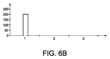
図6A〜図6Dは、本発明による方法の2つの適用例を概略的に示す。2つの例の各々において、新しいエンジンのためのモジュールの一連の累積消費が、1400回の飛行のホライズンを予測するためにシミュレートされている。スタート時には、全てのダメージカウンタはゼロに等しい。また、選択されたホライズンでのシミュレーションが、結果の精度を高めるために少なくとも1000回行われる。 6A-6D schematically show two application examples of the method according to the invention. In each of the two examples, a series of cumulative consumptions of modules for the new engine is simulated to predict a horizon of 1400 flights. At the start, all damage counters are equal to zero. Also, simulation with the selected horizon is performed at least 1000 times to increase the accuracy of the results.
より詳細には、図6A〜図6Bは第1のシナリオを示し、このシナリオにおいて、メンテナンス作業が、それらのトリガー時に個々に実行される。図6Aは、対応するダメージカウンタにより識別されたメンテナンス作業の分布を示す。取り外しの時間間隔が時々非常に短くなり得ることに気づかれよう。また、図6Bは、取り外しごとの検査数の分布を示し、個々の取り外しが200であることを示す。 More specifically, FIGS. 6A-6B illustrate a first scenario, in which maintenance operations are performed individually upon their triggering. FIG. 6A shows the distribution of maintenance work identified by the corresponding damage counter. You will notice that the removal time interval can sometimes be very short. FIG. 6B also shows the distribution of the number of inspections for each removal, indicating that each removal is 200.
図6C〜図6Dは第2のシナリオを示し、このシナリオにおいては、短い間隔でのメンテナンス作業がグループ化されている。従って、メンテナンスアクションをトリガーしなければならないとき、次の50回飛行の範囲でトリガーされるだろう全てのアクションが予測される。図6Dは、50個の取り外しを含む140個の取り外しの分布を示す。複数のメンテナンス作業がグループ化されており、これが、航空機の利用可能性を第1のシナリオよりも良好にしている。 6C to 6D show a second scenario, in which maintenance operations at short intervals are grouped. Thus, when a maintenance action has to be triggered, all actions that will be triggered in the next 50 flight range are predicted. FIG. 6D shows a distribution of 140 removals including 50 removals. Multiple maintenance operations are grouped, which makes the aircraft availability better than the first scenario.
最後に、本発明が、メンテナンス戦略の事前実行、或いは、エンジン又はエンジンフリートの現在の状態に依存した実行のためのツールであることが留意されよう。すなわち、このツールは、フリートの現在状態を無視する(すなわち推測する)か、又は、フリートの現在状態をリアルタイムで考慮して最良の戦略を選択するために使用できる。 Finally, it should be noted that the present invention is a tool for pre-execution of maintenance strategies or execution depending on the current state of the engine or engine fleet. That is, the tool can be used to ignore (ie, infer) the current state of the fleet or to select the best strategy considering the current state of the fleet in real time.
1 システム
3 コンピュータシステム
5 入力手段
7 処理手段
9 記憶手段
11 出力手段
17 ダメージカウンタ
19 航空機エンジン
31 学習データベース
A モジュール
B コンポーネント
C ダメージカウンタ
E 要素
M ミッション
OP オペレーション作業
S ダメージ上限
T ターゲット
P1 メンテナンスプラン
P2 メンテナンス戦略最適化
1
Claims (11)
前記方法は、
学習データベース(31)から一連のシミュレーションミッションを繰り返し抽出することにより、前記ダメージカウンタ(C1〜Cm)の消費をシミュレートするステップと、
現在のシミュレーションミッションに関連する少なくとも1つのダメージカウンタが前記ダメージカウンタに関連するダメージ上限により制限された所定の値に達するまで、前記複数のダメージカウンタの各々の累積消費を繰り返しごとに測定するステップと、
前記現在のシミュレーションミッションにメンテナンス戦略を適用することで、前記航空機エンジン(19)に対して計画されるメンテナンス作業を示すメンテナンスインジケータを決定するステップと、
を含むことを特徴とする、方法。 A method of predicting maintenance work to be performed on an aircraft engine with multiple components monitored by multiple damage counters, each damage counter being limited by a corresponding damage limit,
The method
Simulating consumption of the damage counters (C1-Cm) by repeatedly extracting a series of simulation missions from the learning database (31);
Measuring the cumulative consumption of each of the plurality of damage counters repeatedly until at least one damage counter associated with a current simulation mission reaches a predetermined value limited by a damage limit associated with the damage counter; ,
Determining a maintenance indicator indicative of a maintenance operation planned for the aircraft engine (19) by applying a maintenance strategy to the current simulation mission;
A method comprising the steps of:
様々な戦略のための妥協インジケータを比較して最適なメンテナンス戦略を選択するステップと、
を含むことを特徴とする、請求項1に記載の方法。 For each application of the current strategy, a series of different maintenance strategies, including the determination of cost and validity indicators associated with the current strategy, and the determination of compromise indicators as a function of the cost and effectiveness indicators. Applying steps,
Comparing compromise indicators for different strategies and selecting the best maintenance strategy;
The method of claim 1, comprising:
各ダメージカウンタの前記累積消費を決められた回数の飛行まで推定するステップと、
ダメージ上限に達したダメージカウンタに関連するメンテナンス作業をグループ化するステップと、
を含むことを特徴とする、請求項1又は2に記載の方法。 Applying a maintenance strategy
Estimating the cumulative consumption of each damage counter up to a predetermined number of flights;
Grouping maintenance work related to damage counters that have reached the damage limit;
The method according to claim 1, wherein the method comprises:
前記現在のシミュレーションミッションのダメージカウンタの消費を、中間閾値又はダメージ上限より下の上限と比較するステップと、
前記中間上限に達したダメージカウンタに関連するメンテナンス作業をグループ化するステップと、
を含むことを特徴とする、請求項1又は2に記載の方法。 Applying a maintenance strategy
Comparing the consumption of the current simulation mission damage counter with an intermediate threshold or an upper limit below the damage upper limit;
Grouping maintenance work related to damage counters that have reached the intermediate upper limit;
The method according to claim 1, wherein the method comprises:
各メンテナンスインジケータに関連する前記消費値の平均を算出するステップと、
を含むことを特徴とする、請求項1〜4のうちいずれか一項に記載の方法。 Determining a series of consumption values associated with each maintenance indicator by repeating the consumption of the simulated damage counter multiple times;
Calculating an average of the consumption values associated with each maintenance indicator;
The method according to claim 1, comprising:
一連の経験ミッションと、前記経験ミッションの各々に関連するポテンシャルセンサの消費と、
ポテンシャルセンサに関連するダメージ上限と、対応するメンテナンスアクションを含む所定のメンテナンスプランと、
を含むことを特徴とする、請求項1〜5のうちいずれか一項に記載の方法。 The learning database is
A series of experience missions and the consumption of potential sensors associated with each of the experience missions;
A predetermined maintenance plan that includes the damage limit associated with the potential sensor and the corresponding maintenance action;
The method according to claim 1, comprising:
前記ミッションインジケータは、ミッション毎の重大性インジケータと、ミッション毎の飛行期間インジケータと、ミッションタイプインジケータとを含むことを特徴とする、請求項6に記載の方法。 The learning database further includes a mission indicator,
The method of claim 6, wherein the mission indicators include a mission criticality indicator, a mission duration flight indicator, and a mission type indicator.
前記システムは、
経験ミッションを含む学習データベース(31)から一連のシミュレーションミッションを繰り返し抽出することにより、前記ダメージカウンタ(C1〜Cm)の消費をシミュレートするように構成された処理手段(7)と、
現在のシミュレーションミッションに関連する少なくとも1つのダメージカウンタが前記ダメージカウンタに関連するダメージ上限に達するまで、前記複数のダメージカウンタの各々の累積消費を繰り返しごとに測定するように構成された処理手段(7)と、
前記現在のシミュレーションミッションにメンテナンス戦略を適用することで、前記航空機エンジンに対して実行されるメンテナンス作業を示すメンテナンスインジケータを決定するように構成された処理手段(7)と、
を備える、システム。 A system for predicting maintenance work to be performed on aircraft engines with multiple components monitored by multiple damage counters, each damage counter being limited by a corresponding damage limit,
The system
Processing means (7) configured to simulate consumption of the damage counters (C1-Cm) by repeatedly extracting a series of simulation missions from a learning database (31) including experience missions;
Processing means (7) configured to measure each cumulative consumption of each of the plurality of damage counters repeatedly until at least one damage counter associated with the current simulation mission reaches a damage limit associated with the damage counter. )When,
Processing means (7) configured to determine a maintenance indicator indicative of a maintenance operation performed on the aircraft engine by applying a maintenance strategy to the current simulation mission;
A system comprising:
Applications Claiming Priority (3)
| Application Number | Priority Date | Filing Date | Title |
|---|---|---|---|
| FR1362549A FR3014952B1 (en) | 2013-12-13 | 2013-12-13 | PREDICTION OF MAINTENANCE OPERATIONS TO BE APPLIED TO A MOTOR |
| FR1362549 | 2013-12-13 | ||
| PCT/FR2014/053148 WO2015086957A2 (en) | 2013-12-13 | 2014-12-03 | Forecasting maintenance operations to be applied to an engine |
Publications (2)
| Publication Number | Publication Date |
|---|---|
| JP2017502193A true JP2017502193A (en) | 2017-01-19 |
| JP6552500B2 JP6552500B2 (en) | 2019-07-31 |
Family
ID=50933205
Family Applications (1)
| Application Number | Title | Priority Date | Filing Date |
|---|---|---|---|
| JP2016536978A Active JP6552500B2 (en) | 2013-12-13 | 2014-12-03 | Predicting maintenance work to be done on aircraft engines |
Country Status (9)
| Country | Link |
|---|---|
| US (1) | US11243525B2 (en) |
| EP (1) | EP3080670A2 (en) |
| JP (1) | JP6552500B2 (en) |
| CN (1) | CN105829982B (en) |
| BR (1) | BR112016012131B1 (en) |
| CA (1) | CA2932933C (en) |
| FR (1) | FR3014952B1 (en) |
| RU (1) | RU2670937C9 (en) |
| WO (1) | WO2015086957A2 (en) |
Cited By (1)
| Publication number | Priority date | Publication date | Assignee | Title |
|---|---|---|---|---|
| WO2018155529A1 (en) * | 2017-02-27 | 2018-08-30 | 三菱重工業株式会社 | Aircraft management device, method, and program |
Families Citing this family (9)
| Publication number | Priority date | Publication date | Assignee | Title |
|---|---|---|---|---|
| GB201608047D0 (en) | 2016-05-09 | 2016-06-22 | Rolls Royce Plc | Component lifing |
| US10234359B2 (en) * | 2016-05-23 | 2019-03-19 | United Technologies Corporation | Gas turbine engine with lifing calculations based upon actual usage |
| US10384808B2 (en) * | 2016-12-02 | 2019-08-20 | General Electric Company | Control system and method |
| US11180265B2 (en) | 2016-12-02 | 2021-11-23 | General Electric Company | Control system and method |
| US10589300B2 (en) | 2016-12-02 | 2020-03-17 | General Electric Company | Coating system and method |
| US11067002B2 (en) | 2016-12-06 | 2021-07-20 | General Electric Company | Gas turbine engine maintenance tool |
| FR3087888B1 (en) * | 2018-10-31 | 2020-10-09 | Safran Aircraft Engines | DEVICE AND METHOD FOR MONITORING THE LIFETIME OF A HYDRAULIC EQUIPMENT OF AN AIRCRAFT |
| US11226358B2 (en) * | 2019-02-27 | 2022-01-18 | Caterpillar Inc. | Power system damage analysis and control system |
| CN110057590B (en) * | 2019-04-15 | 2021-05-07 | 中国航发湖南动力机械研究所 | Aircraft engine outfield data management system and method facing machine group |
Citations (3)
| Publication number | Priority date | Publication date | Assignee | Title |
|---|---|---|---|---|
| JPH0844421A (en) * | 1994-07-29 | 1996-02-16 | Toshiba Corp | Device for supporting maintenance and management of equipment |
| JP2006146928A (en) * | 2004-11-19 | 2006-06-08 | United Technol Corp <Utc> | Maintenance planning method and computer support system |
| JP2007183929A (en) * | 2005-12-07 | 2007-07-19 | Mitsubishi Heavy Ind Ltd | Method for making equipment maintenance plan of plant facility |
Family Cites Families (49)
| Publication number | Priority date | Publication date | Assignee | Title |
|---|---|---|---|---|
| US4926362A (en) * | 1988-04-07 | 1990-05-15 | The United States Of America As Represented By The Secretary Of The Air Force | Airbase sortie generation analysis model (ABSGAM) |
| CN1238848A (en) * | 1996-11-27 | 1999-12-15 | 森德斯特兰德公司 | Method of maintaining components suject to fatigue failure |
| US6408258B1 (en) * | 1999-12-20 | 2002-06-18 | Pratt & Whitney Canada Corp. | Engine monitoring display for maintenance management |
| US7283932B2 (en) * | 2000-07-20 | 2007-10-16 | Albihns Goteborg Ab | Method for estimating damage to an object, and method and system for controlling the use of the object |
| US6980959B1 (en) * | 2000-10-17 | 2005-12-27 | Accenture Llp | Configuring mechanical equipment |
| US6968293B2 (en) * | 2000-12-07 | 2005-11-22 | Juisclan Holding Gmbh | Method and apparatus for optimizing equipment maintenance |
| US20030078708A1 (en) * | 2001-10-18 | 2003-04-24 | Harper David J. | Productivity and reliability enhancement program |
| US8073653B2 (en) * | 2002-12-23 | 2011-12-06 | Caterpillar Inc. | Component life indicator |
| US7627459B2 (en) * | 2004-01-08 | 2009-12-01 | Georgia Tech Research Corporation | Systems and methods for reliability and performability assessment |
| US7487029B2 (en) * | 2004-05-21 | 2009-02-03 | Pratt & Whitney Canada | Method of monitoring gas turbine engine operation |
| US20080172268A1 (en) * | 2005-01-13 | 2008-07-17 | Standard Aero (San Antonio), Inc. | System and method of enhancing cost performance of mechanical systems including life-limited parts |
| US20060190280A1 (en) * | 2005-02-22 | 2006-08-24 | Lockheed Martin Corporation | Method and apparatus for management for use in fleet service and logistics |
| US20070118502A1 (en) * | 2005-11-18 | 2007-05-24 | Aragones James K | Methods and systems for managing a fleet of assets |
| US10248914B2 (en) * | 2005-11-29 | 2019-04-02 | The Boeing Company | Sustaining a fleet of configuration-controlled assets |
| US20100262442A1 (en) * | 2006-07-20 | 2010-10-14 | Standard Aero, Inc. | System and method of projecting aircraft maintenance costs |
| US7702436B2 (en) * | 2006-09-29 | 2010-04-20 | Standard Aero (San Antonio), Inc. | System and method of troubleshooting aircraft system failures |
| US8620714B2 (en) * | 2006-11-28 | 2013-12-31 | The Boeing Company | Prognostic condition assessment decision aid |
| US8560376B2 (en) * | 2007-05-31 | 2013-10-15 | Airbus Operations S.A.S. | Method, system, and computer program product for a maintenance optimization model |
| FR2917715B1 (en) * | 2007-06-20 | 2009-12-25 | Eurocopter France | METHOD AND DEVICE FOR MONITORING AND CONTROLLING A GYRANE TURBOMOTOR |
| US20100250448A1 (en) * | 2007-10-09 | 2010-09-30 | Towe Eric S | Logistics, maintenance, and operations data visualization system and method |
| US8112368B2 (en) * | 2008-03-10 | 2012-02-07 | The Boeing Company | Method, apparatus and computer program product for predicting a fault utilizing multi-resolution classifier fusion |
| FR2934397A1 (en) * | 2008-07-28 | 2010-01-29 | Eurocopter France | IMPROVED METHOD FOR ORGANIZING AIRCRAFT MAINTENANCE |
| FR2935186B1 (en) * | 2008-08-20 | 2010-09-17 | Airbus France | METHOD AND DEVICE FOR AIDING THE DIAGNOSIS AND DECISION TO OPERATE AN AIRCRAFT |
| US20100063933A1 (en) * | 2008-09-09 | 2010-03-11 | Eurocopter | Method of optimizing the availability of an aircraft or of a fleet of aircraft |
| US8117007B2 (en) * | 2008-09-12 | 2012-02-14 | The Boeing Company | Statistical analysis for maintenance optimization |
| DE102008049170C5 (en) * | 2008-09-26 | 2020-04-09 | MTU Aero Engines AG | Device and method for monitoring the service life |
| US8165826B2 (en) * | 2008-09-30 | 2012-04-24 | The Boeing Company | Data driven method and system for predicting operational states of mechanical systems |
| US20100217638A1 (en) * | 2009-02-23 | 2010-08-26 | Bae Systems Information And Electronic Systems Integration, Inc. | In service support center and method of operation |
| US20160005242A1 (en) * | 2009-03-05 | 2016-01-07 | United States Government As Represented By The Secretary Of The Navy | Predictive Automated Maintenance System (PAMS) |
| US8340948B1 (en) * | 2009-09-29 | 2012-12-25 | The Boeing Company | Fleet performance optimization tool for aircraft health management |
| GB0917527D0 (en) * | 2009-10-07 | 2009-11-25 | Optimized Systems And Solution | Asset management system |
| US8868284B2 (en) * | 2009-11-12 | 2014-10-21 | Sikorsky Aircraft Corporation | Virtual monitoring of aircraft fleet loads |
| JP2011165047A (en) * | 2010-02-12 | 2011-08-25 | Mitsubishi Heavy Ind Ltd | Maintenance planning system, maintenance planning apparatus, control method, and program |
| US8355830B2 (en) * | 2010-03-30 | 2013-01-15 | Aurora Flight Sciences Corporation | Aircraft health monitoring and design for condition |
| US9167339B2 (en) * | 2010-07-07 | 2015-10-20 | Iii Holdings 4, Llc | Hearing damage limiting headphones |
| FR2970358B1 (en) * | 2011-01-06 | 2019-04-12 | Airbus Helicopters | PROGNOSTIC OF DURATION BEFORE MAINTENANCE BY FUSION BETWEEN MODELING AND SIMULATION, FOR ELECTRONIC EQUIPMENTS ON BOARD IN AN AIRCRAFT |
| FR2971595B1 (en) * | 2011-02-15 | 2013-03-22 | Snecma | MONITORING AN AIRCRAFT ENGINE TO ANTICIPATE MAINTENANCE OPERATIONS |
| FR2972025B1 (en) * | 2011-02-25 | 2016-03-04 | Snecma | PREDICTION OF MAINTENANCE OPERATIONS ON AN AIRCRAFT ENGINE |
| US8781982B1 (en) * | 2011-09-23 | 2014-07-15 | Lockheed Martin Corporation | System and method for estimating remaining useful life |
| US8560368B1 (en) * | 2011-11-18 | 2013-10-15 | Lockheed Martin Corporation | Automated constraint-based scheduling using condition-based maintenance |
| US8782467B2 (en) * | 2012-02-01 | 2014-07-15 | Honeywell International Inc. | Systems and methods for creating a near optimal maintenance plan |
| US8959065B2 (en) * | 2012-04-09 | 2015-02-17 | Mitek Analytics, LLC | System and method for monitoring distributed asset data |
| FR2991788B1 (en) | 2012-06-08 | 2023-03-24 | Snecma | FORECAST OF MAINTENANCE OPERATIONS TO BE APPLIED ON AN ENGINE |
| US20140089029A1 (en) * | 2012-09-21 | 2014-03-27 | Enphase Energy, Inc. | Method and apparatus for scheduling maintenance of alternative energy systems |
| CN103020422A (en) * | 2012-11-12 | 2013-04-03 | 中航沈飞民用飞机有限责任公司 | Method for calculating maintenance time interval of civil aircraft system |
| US20140244328A1 (en) * | 2013-02-22 | 2014-08-28 | Vestas Wind Systems A/S | Wind turbine maintenance optimizer |
| CN103399994B (en) * | 2013-07-23 | 2016-09-28 | 中国人民解放军海军航空工程学院 | Military aircraft regular inspection flow optimization method based on probabilistic network scheduling technology |
| WO2015195184A2 (en) * | 2014-04-02 | 2015-12-23 | Sikorsky Aircraft Corporation | System and method for health assessment of aircraft structure |
| EP3173762B1 (en) * | 2015-11-25 | 2020-03-18 | Sikorsky Aircraft Corporation | Systems and methods for fatigue monitoring |
-
2013
- 2013-12-13 FR FR1362549A patent/FR3014952B1/en active Active
-
2014
- 2014-12-03 EP EP14821787.0A patent/EP3080670A2/en active Pending
- 2014-12-03 US US15/102,455 patent/US11243525B2/en active Active
- 2014-12-03 JP JP2016536978A patent/JP6552500B2/en active Active
- 2014-12-03 WO PCT/FR2014/053148 patent/WO2015086957A2/en active Application Filing
- 2014-12-03 CN CN201480067272.1A patent/CN105829982B/en active Active
- 2014-12-03 BR BR112016012131-7A patent/BR112016012131B1/en active IP Right Grant
- 2014-12-03 CA CA2932933A patent/CA2932933C/en active Active
- 2014-12-03 RU RU2016126807A patent/RU2670937C9/en active
Patent Citations (3)
| Publication number | Priority date | Publication date | Assignee | Title |
|---|---|---|---|---|
| JPH0844421A (en) * | 1994-07-29 | 1996-02-16 | Toshiba Corp | Device for supporting maintenance and management of equipment |
| JP2006146928A (en) * | 2004-11-19 | 2006-06-08 | United Technol Corp <Utc> | Maintenance planning method and computer support system |
| JP2007183929A (en) * | 2005-12-07 | 2007-07-19 | Mitsubishi Heavy Ind Ltd | Method for making equipment maintenance plan of plant facility |
Cited By (3)
| Publication number | Priority date | Publication date | Assignee | Title |
|---|---|---|---|---|
| WO2018155529A1 (en) * | 2017-02-27 | 2018-08-30 | 三菱重工業株式会社 | Aircraft management device, method, and program |
| JP2018142106A (en) * | 2017-02-27 | 2018-09-13 | 三菱重工業株式会社 | Aircraft management device and method, and program |
| US11325725B2 (en) | 2017-02-27 | 2022-05-10 | Mitsubishi Heavy Industries, Ltd. | Aircraft management device, method, and program |
Also Published As
| Publication number | Publication date |
|---|---|
| WO2015086957A2 (en) | 2015-06-18 |
| WO2015086957A3 (en) | 2016-06-02 |
| RU2670937C9 (en) | 2018-11-21 |
| EP3080670A2 (en) | 2016-10-19 |
| BR112016012131B1 (en) | 2022-06-21 |
| BR112016012131A2 (en) | 2017-08-08 |
| FR3014952A1 (en) | 2015-06-19 |
| JP6552500B2 (en) | 2019-07-31 |
| US20160313728A1 (en) | 2016-10-27 |
| FR3014952B1 (en) | 2016-01-22 |
| RU2670937C1 (en) | 2018-10-25 |
| US11243525B2 (en) | 2022-02-08 |
| CA2932933C (en) | 2023-06-27 |
| CN105829982A (en) | 2016-08-03 |
| CN105829982B (en) | 2019-08-09 |
| CA2932933A1 (en) | 2015-06-18 |
Similar Documents
| Publication | Publication Date | Title |
|---|---|---|
| JP6552500B2 (en) | Predicting maintenance work to be done on aircraft engines | |
| US8868287B2 (en) | Prediction of maintenance operations on an aircraft engine | |
| US10318664B2 (en) | Determining life consumption of a mechanical part | |
| Wang et al. | A multi-objective optimization of imperfect preventive maintenance policy for dependent competing risk systems with hidden failure | |
| JP6023882B2 (en) | Reliable prediction of machine part life consumption | |
| RU2005116169A (en) | METHOD AND SYSTEM OF ANALYSIS AND ASSESSMENT OF SAFETY OF A TECHNOLOGICAL PROCESS | |
| CN107545095A (en) | Forecasting Methodology and system for the structure repair during aircraft overhaul | |
| US11416007B2 (en) | Computer-implemented method and system for evaluating uncertainty in trajectory prediction | |
| CN111415027A (en) | Method and device for constructing component prediction model | |
| JP5993273B2 (en) | Decision support system and method | |
| Landowski | Example of applying markov decision process o model vehicle maintenance process | |
| CN104657614A (en) | Product site failure rate calculation method | |
| Kumar et al. | Model-free approach and methodology for data anomaly detection for real time diagnostic solution | |
| Pokorádi et al. | Markovian Model-based Sensitivity Analysis of Maintenance System | |
| Tajiani et al. | Optimizing the Maintenance Threshold in Presence of Shocks: A Numerical framework for Systems with Non-monotonic Degradation | |
| Tian et al. | Data partition based reliability modeling | |
| Awadid et al. | AI Systems Trustworthiness Assessment: State of the Art | |
| Antonov et al. | Mathematical model of the residual lifetime of NPP equipment calculation based on operational information specific type | |
| Qiuzhuang | Development of Intelligent Maintenance Decision Support Systems for Asset Management | |
| Jung et al. | A Classification and Selection of Reliability Growth Models | |
| Brown | Reliability analysis for systems with stochastic and spatial dependence | |
| Baker | A methodology for sensitivity analysis of maintenance and reliability models | |
| Kumar et al. | Empirical analysis of software reliability growth model for three-tier client-server system |
Legal Events
| Date | Code | Title | Description |
|---|---|---|---|
| A621 | Written request for application examination |
Free format text: JAPANESE INTERMEDIATE CODE: A621 Effective date: 20171114 |
|
| A977 | Report on retrieval |
Free format text: JAPANESE INTERMEDIATE CODE: A971007 Effective date: 20180904 |
|
| A131 | Notification of reasons for refusal |
Free format text: JAPANESE INTERMEDIATE CODE: A131 Effective date: 20180918 |
|
| A601 | Written request for extension of time |
Free format text: JAPANESE INTERMEDIATE CODE: A601 Effective date: 20181218 |
|
| A521 | Request for written amendment filed |
Free format text: JAPANESE INTERMEDIATE CODE: A523 Effective date: 20190207 |
|
| TRDD | Decision of grant or rejection written | ||
| A01 | Written decision to grant a patent or to grant a registration (utility model) |
Free format text: JAPANESE INTERMEDIATE CODE: A01 Effective date: 20190604 |
|
| A61 | First payment of annual fees (during grant procedure) |
Free format text: JAPANESE INTERMEDIATE CODE: A61 Effective date: 20190702 |
|
| R150 | Certificate of patent or registration of utility model |
Ref document number: 6552500 Country of ref document: JP Free format text: JAPANESE INTERMEDIATE CODE: R150 |
|
| R250 | Receipt of annual fees |
Free format text: JAPANESE INTERMEDIATE CODE: R250 |
|
| R250 | Receipt of annual fees |
Free format text: JAPANESE INTERMEDIATE CODE: R250 |