JP2017501544A - Membrane electrode assembly and manufacturing method thereof - Google Patents
Membrane electrode assembly and manufacturing method thereof Download PDFInfo
- Publication number
- JP2017501544A JP2017501544A JP2016541357A JP2016541357A JP2017501544A JP 2017501544 A JP2017501544 A JP 2017501544A JP 2016541357 A JP2016541357 A JP 2016541357A JP 2016541357 A JP2016541357 A JP 2016541357A JP 2017501544 A JP2017501544 A JP 2017501544A
- Authority
- JP
- Japan
- Prior art keywords
- gas diffusion
- diffusion layer
- catalyst
- microporous
- layer
- Prior art date
- Legal status (The legal status is an assumption and is not a legal conclusion. Google has not performed a legal analysis and makes no representation as to the accuracy of the status listed.)
- Ceased
Links
Images

Classifications
-
- H—ELECTRICITY
- H01—ELECTRIC ELEMENTS
- H01M—PROCESSES OR MEANS, e.g. BATTERIES, FOR THE DIRECT CONVERSION OF CHEMICAL ENERGY INTO ELECTRICAL ENERGY
- H01M8/00—Fuel cells; Manufacture thereof
- H01M8/02—Details
- H01M8/0271—Sealing or supporting means around electrodes, matrices or membranes
-
- H—ELECTRICITY
- H01—ELECTRIC ELEMENTS
- H01M—PROCESSES OR MEANS, e.g. BATTERIES, FOR THE DIRECT CONVERSION OF CHEMICAL ENERGY INTO ELECTRICAL ENERGY
- H01M8/00—Fuel cells; Manufacture thereof
- H01M8/10—Fuel cells with solid electrolytes
- H01M8/1004—Fuel cells with solid electrolytes characterised by membrane-electrode assemblies [MEA]
-
- H—ELECTRICITY
- H01—ELECTRIC ELEMENTS
- H01M—PROCESSES OR MEANS, e.g. BATTERIES, FOR THE DIRECT CONVERSION OF CHEMICAL ENERGY INTO ELECTRICAL ENERGY
- H01M4/00—Electrodes
- H01M4/86—Inert electrodes with catalytic activity, e.g. for fuel cells
- H01M4/88—Processes of manufacture
- H01M4/8803—Supports for the deposition of the catalytic active composition
- H01M4/881—Electrolytic membranes
-
- H—ELECTRICITY
- H01—ELECTRIC ELEMENTS
- H01M—PROCESSES OR MEANS, e.g. BATTERIES, FOR THE DIRECT CONVERSION OF CHEMICAL ENERGY INTO ELECTRICAL ENERGY
- H01M8/00—Fuel cells; Manufacture thereof
- H01M8/02—Details
- H01M8/0202—Collectors; Separators, e.g. bipolar separators; Interconnectors
- H01M8/023—Porous and characterised by the material
- H01M8/0234—Carbonaceous material
-
- H—ELECTRICITY
- H01—ELECTRIC ELEMENTS
- H01M—PROCESSES OR MEANS, e.g. BATTERIES, FOR THE DIRECT CONVERSION OF CHEMICAL ENERGY INTO ELECTRICAL ENERGY
- H01M8/00—Fuel cells; Manufacture thereof
- H01M8/02—Details
- H01M8/0202—Collectors; Separators, e.g. bipolar separators; Interconnectors
- H01M8/0247—Collectors; Separators, e.g. bipolar separators; Interconnectors characterised by the form
-
- H—ELECTRICITY
- H01—ELECTRIC ELEMENTS
- H01M—PROCESSES OR MEANS, e.g. BATTERIES, FOR THE DIRECT CONVERSION OF CHEMICAL ENERGY INTO ELECTRICAL ENERGY
- H01M8/00—Fuel cells; Manufacture thereof
- H01M8/02—Details
- H01M8/0202—Collectors; Separators, e.g. bipolar separators; Interconnectors
- H01M8/0258—Collectors; Separators, e.g. bipolar separators; Interconnectors characterised by the configuration of channels, e.g. by the flow field of the reactant or coolant
-
- Y—GENERAL TAGGING OF NEW TECHNOLOGICAL DEVELOPMENTS; GENERAL TAGGING OF CROSS-SECTIONAL TECHNOLOGIES SPANNING OVER SEVERAL SECTIONS OF THE IPC; TECHNICAL SUBJECTS COVERED BY FORMER USPC CROSS-REFERENCE ART COLLECTIONS [XRACs] AND DIGESTS
- Y02—TECHNOLOGIES OR APPLICATIONS FOR MITIGATION OR ADAPTATION AGAINST CLIMATE CHANGE
- Y02E—REDUCTION OF GREENHOUSE GAS [GHG] EMISSIONS, RELATED TO ENERGY GENERATION, TRANSMISSION OR DISTRIBUTION
- Y02E60/00—Enabling technologies; Technologies with a potential or indirect contribution to GHG emissions mitigation
- Y02E60/30—Hydrogen technology
- Y02E60/50—Fuel cells
Landscapes
- Engineering & Computer Science (AREA)
- Manufacturing & Machinery (AREA)
- Chemical & Material Sciences (AREA)
- Chemical Kinetics & Catalysis (AREA)
- Electrochemistry (AREA)
- General Chemical & Material Sciences (AREA)
- Life Sciences & Earth Sciences (AREA)
- Sustainable Development (AREA)
- Sustainable Energy (AREA)
- Inert Electrodes (AREA)
- Fuel Cell (AREA)
Abstract
膜電極接合体であって、その主表面上に第1の微多孔層を有する第1のガス拡散層を含み、前記第1の微多孔層が主表面を有し、前記第1の微多孔層の主表面が、微多孔性物質を実質的に含まない不連続な領域を内部に有し、及び、前記第1の不連続な領域の少なくとも一部が内部に接着剤を有する、膜電極接合体、及びその製造方法。本明細書に記載する膜電極接合体は、例えば、燃料電池において有用である。A membrane electrode assembly comprising a first gas diffusion layer having a first microporous layer on a main surface thereof, the first microporous layer having a main surface, and the first microporous layer A membrane electrode in which the main surface of the layer has a discontinuous region substantially free of microporous material therein, and at least a portion of the first discontinuous region has an adhesive therein Bonded body and manufacturing method thereof. The membrane electrode assembly described in the present specification is useful, for example, in a fuel cell.
Description
(関連出願の相互参照)
本出願は、2013年12月17日に出願された米国特許仮出願第61/917135号の利益を主張するものであり、その開示内容全体が参照により本明細書に組み込まれる。
(Cross-reference of related applications)
This application claims the benefit of US Provisional Application No. 61/917135, filed December 17, 2013, the entire disclosure of which is incorporated herein by reference.
燃料電池膜電極接合体(MEA)は通常、アノード触媒及びカソード触媒並びに膜層に、結合した、コーティングされた又は積層された、カーボン紙ガス拡散層(GDL)を含む。前記5層構造はいくつかの方法で作成することができるが、多くの場合触媒が膜に結合して、触媒被覆膜(CCM)を形成する。次に微多孔層(MPL)を備えるガス拡散層が触媒被覆膜に結合して、膜電極接合体を形成する。 Fuel cell membrane electrode assemblies (MEA) typically include a carbon paper gas diffusion layer (GDL) bonded, coated or laminated to the anode and cathode catalysts and the membrane layer. The five-layer structure can be made in several ways, but in many cases, the catalyst binds to the membrane to form a catalyst coated membrane (CCM). Next, a gas diffusion layer having a microporous layer (MPL) is bonded to the catalyst-coated membrane to form a membrane electrode assembly.
多くの場合、ガス拡散層の触媒と微多孔層面の間の結合は、望ましくはガス拡散層と触媒被覆膜を一緒に固着する観点から、構造の弱い所である。更に、微多孔層と触媒の間の結合が比較的強い場合でも、微多孔層とガス拡散層繊維の間の結合が構成要素を合わせて保持するのに十分でないこともあり得る。したがって、接着剤がガス拡散層炭素繊維に接触して、強い結合を作成するようなやり方で、ガス拡散層を触媒被覆膜に接着結合することが、有利であり得る。 In many cases, the bond between the catalyst of the gas diffusion layer and the surface of the microporous layer is desirably a weak structure from the viewpoint of fixing the gas diffusion layer and the catalyst-coated membrane together. Furthermore, even if the bond between the microporous layer and the catalyst is relatively strong, the bond between the microporous layer and the gas diffusion layer fibers may not be sufficient to hold the components together. Thus, it may be advantageous to adhesively bond the gas diffusion layer to the catalyst coated membrane in such a way that the adhesive contacts the gas diffusion layer carbon fibers to create a strong bond.
一態様では、本開示は、膜電極接合体であって、膜電極接合体の主表面上に第1の微多孔層を有する第1のガス拡散層を含み、第1の微多孔層が主表面を有し、第1の微多孔層の主表面が、内部に微多孔性物質を実質的に含まない不連続な領域を有し、第1の不連続な領域の少なくとも一部が内部に接着剤を有する、膜電極接合体を説明する。本明細書で使用する場合、「微多孔性物質を実質的に含まない」とは、不連続な領域の少なくとも一部が、ガス拡散層の該当する主表面上に微多孔性物質を有しないことを意味する。 In one aspect, the present disclosure is a membrane electrode assembly including a first gas diffusion layer having a first microporous layer on a main surface of the membrane electrode assembly, the first microporous layer being a main layer. And the main surface of the first microporous layer has a discontinuous region that does not substantially contain a microporous material therein, and at least a part of the first discontinuous region is inside. A membrane electrode assembly having an adhesive will be described. As used herein, “substantially free of microporous material” means that at least some of the discontinuous regions do not have microporous material on the relevant major surface of the gas diffusion layer. Means that.
別の態様において、本開示は、膜電極接合体の第1の製造方法を説明しており、前記方法は、
膜電極接合体の主表面上に第1の微多孔層を有する第1のガス拡散層を提供することであって、第1の微多孔層が主表面領域を有する、ことと、
第1のガス拡散層から第1の微多孔層の一部を除去して、第1の微多孔性物質を実質的に含まない第1のガス拡散層の主表面上に少なくとも第1の領域を提供することと、
第1及び第2の概して対向する主表面を有する触媒被覆膜を提供することであって、第1主表面がアノード触媒を含み、第2主表面がカソード触媒を含む、ことと、
第1のガス拡散層を触媒被覆膜のアノード触媒に固着することであって、第1のガス拡散層と触媒被覆膜とが共に結合するのを少なくとも部分的に助ける、第1の微多孔性物質を実質的に含まない、第1のガス拡散層の第1の領域の少なくとも一部に配設された第1の接着剤がある、ことと、
第2のガス拡散層を触媒被覆膜のカソード触媒に固着して、
膜電極接合体を提供することと、を含む方法である。
In another aspect, the present disclosure describes a first method of manufacturing a membrane electrode assembly, the method comprising:
Providing a first gas diffusion layer having a first microporous layer on a main surface of a membrane electrode assembly, the first microporous layer having a main surface region;
A part of the first microporous layer is removed from the first gas diffusion layer, and at least the first region on the main surface of the first gas diffusion layer substantially free of the first microporous material Providing
Providing a catalyst coated membrane having first and second generally opposing major surfaces, wherein the first major surface comprises an anode catalyst and the second major surface comprises a cathode catalyst;
Fixing a first gas diffusion layer to the anode catalyst of the catalyst-coated membrane, wherein the first fine diffusion layer and the catalyst-coated membrane help at least partially bond together. There is a first adhesive disposed in at least a portion of the first region of the first gas diffusion layer that is substantially free of porous material;
Fixing the second gas diffusion layer to the cathode catalyst of the catalyst-coated membrane;
Providing a membrane electrode assembly.
別の態様において、本開示は、膜電極接合体の第2の製造方法を説明しており、前記方法は、
少なくとも1つのマスクを用いて、その主表面上の第1のガス拡散層上へ微多孔層をコーティングして、その主表面上に第1の微多孔層を有する第1のガス拡散層を形成することであって、第1の微多孔層が主表面を有し、第1の微多孔層の主表面がその内部に第1の微多孔性物質を実質的に含まない不連続領域を有し、少なくとも1つの不連続な領域の一部が第1のガス拡散層の作用面積にある、ことと、
第1及び第2の概して対向する主表面を有する触媒被覆膜を提供することであって、第1主表面がアノード触媒を含み、第2主表面がカソード触媒を含む、ことと、
第1のガス拡散層を触媒被覆膜のアノード触媒に固着することであって、第1のガス拡散層と触媒被覆膜とが共に結合するのを少なくとも部分的に助ける、第1の微多孔性物質を実質的に含まない、第1のガス拡散層の第1の領域の少なくとも一部に配設された第1の接着剤がある、ことと、
第2のガス拡散層を触媒被覆膜のカソード触媒に固着して、
膜電極接合体を提供することと、を含む方法である。
In another aspect, the present disclosure describes a second method of manufacturing a membrane electrode assembly, the method comprising:
Coating the microporous layer on the first gas diffusion layer on the main surface using at least one mask to form a first gas diffusion layer having the first microporous layer on the main surface The first microporous layer has a main surface, and the main surface of the first microporous layer has a discontinuous region substantially free of the first microporous material therein. A portion of the at least one discontinuous region is in the active area of the first gas diffusion layer;
Providing a catalyst coated membrane having first and second generally opposing major surfaces, wherein the first major surface comprises an anode catalyst and the second major surface comprises a cathode catalyst;
Fixing a first gas diffusion layer to the anode catalyst of the catalyst-coated membrane, wherein the first fine diffusion layer and the catalyst-coated membrane help at least partially bond together. There is a first adhesive disposed in at least a portion of the first region of the first gas diffusion layer that is substantially free of porous material;
Fixing the second gas diffusion layer to the cathode catalyst of the catalyst-coated membrane;
Providing a membrane electrode assembly.
本明細書に記載する膜電極接合体は、例えば、燃料電池において有用である。本明細書に記載される膜電極接合体の実施形態の利点は、良好な取り扱い性を含み、その結果、構成要素は概して、十分に合わせて保持されて、別途、燃料電池スタックに組み立てられる必要がない。ガス拡散層を接着結合することは、作用面積へのガス拡散層の配列を改善できると共に、スタック内でこの配列を保持するのに役立つ。スタック製造者が、スタック製造速度のため、個々の要素とは対照的に、完全に一体化された膜電極接合体を供給されることでも有利である。 The membrane electrode assembly described in the present specification is useful, for example, in a fuel cell. The advantages of the membrane electrode assembly embodiments described herein include good handling, so that the components generally need to be held together and assembled separately into a fuel cell stack. There is no. Adhesive bonding of the gas diffusion layers can improve the alignment of the gas diffusion layers to the active area and help maintain this alignment in the stack. It is also advantageous for the stack manufacturer to be supplied with a fully integrated membrane electrode assembly, as opposed to individual elements, due to the stack manufacturing speed.
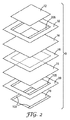
図1を参照すると、燃料電池10は、本明細書に記載される例示の膜電極接合体9を含む。膜電極接合体9は、アノード14に隣接する、第1のガス拡散層(GDL)12を含む。電解質膜16が、アノード14に隣接する。カソード18は電解質膜16に隣接し、第2のガス拡散層19はカソード18に隣接する。GDL 12及び19は、拡散集電体(DCC)又は流体輸送層(FTL)と呼ばれることもある。動作中、水素燃料が燃料電池10のアノード部分に導入され、第1のガス拡散層12を通過し、アノード14を通過する。アノード14において、水素燃料は、水素イオン(H+)と電子(e−)に分離される。
Referring to FIG. 1, a
電解質膜16は、水素イオン、つまりプロトンのみ電解質膜16を通過させて、燃料電池10のカソード部分に到達させる。電子は、電解質膜16を通過することはできないが、その代わりに電流の形で外部電気回路を通じて流れることができる。この電流は、例えば、電動モータなどの電気負荷17に電力を供給することができ、又は蓄電池などのエネルギ貯蔵装置に向けることができる。
The
第2のガス拡散層19を介して燃料電池10のカソード側に酸素が流れ込む。酸素がカソード18を通過するとき、酸素、プロトン及び電子が結合して、水及び熱が発生する。
Oxygen flows into the cathode side of the
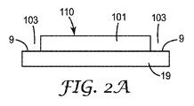
図2は、本明細書に記載される例示の膜電極接合体9の詳細を提供する。本明細書に記載される膜電極接合体9は、その主表面99に第1の微多孔層101を有する第1のガス拡散層9を含む。第1の微多孔層101は、主表面110を有する。第1の微多孔層9の主表面99は、その内部に微多孔性物質を実質的に含まない不連続な領域103を有する。第1の不連続な領域103の少なくとも一部は、内部に接着剤105を有する。いくつかの実施形態では、例えば、ここで図示するように、少なくとも1つの不連続な領域103の少なくとも一部は、作用面積内にある。任意に、第2の微多孔層201を有する第2のガス拡散層19は、その内部に微多孔性物質を実質的に含まない不連続な領域203を有する。いくつかの実施形態では、例えば、ここで図示するように、第1の不連続な領域203の少なくとも一部は、内部に接着剤205を有する。いくつかの実施形態では、例えば、ここで図示するように、少なくとも1つの不連続な領域203の少なくとも一部は、作用面積内にある。本明細書で使用する場合、「作用面積」とは、電気化学的燃料電池反応を起こすのに利用可能な、ガス拡散層表面の主表面が触媒表面と隣接する場合の、ガス拡散層の面積を意味する。
FIG. 2 provides details of the exemplary
図2は、触媒被覆膜のアノード触媒に固着して、内部に連続な領域を有する例示の拡散層、及び、触媒被覆膜のカソード触媒に固着して、内部に不連続な領域を有する又は有さないガス拡散層を示している。しかし、本明細書に記載される膜電極接合体の他の例示の実施形態は、触媒被覆膜のカソード触媒に固着して、内部に不連続な領域を有する拡散層、及び、触媒被覆膜のアノード触媒に固着して、内部に不連続な領域を有する又は有さないガス拡散層を含む。 FIG. 2 shows an exemplary diffusion layer fixed to the anode catalyst of the catalyst-coated membrane and having a continuous region inside, and a non-continuous region fixed to the cathode catalyst of the catalyst-coated membrane and inside. Or the gas diffusion layer which does not have is shown. However, other exemplary embodiments of the membrane electrode assembly described herein include a diffusion layer that adheres to the cathode catalyst of the catalyst coated membrane and has a discontinuous region therein, and a catalyst coating. It includes a gas diffusion layer fixed to the anode catalyst of the membrane and having or not having a discontinuous region therein.
いくつかの実施形態では、ガス拡散層の不連続な領域とは、複数のチャネルである。いくつかの実施形態では、微多孔性物質を実質的に含まない不連続な領域の少なくとも一部は、複数の非接続チャネルである。いくつかの実施形態では、微多孔性物質を実質的に含まない不連続な領域の少なくとも一部は、複数の接続チャネルである。いくつかの実施形態では、不連続な領域の少なくとも一部は、パターンの形態である。 In some embodiments, the discontinuous region of the gas diffusion layer is a plurality of channels. In some embodiments, at least some of the discontinuous regions that are substantially free of microporous material are a plurality of unconnected channels. In some embodiments, at least some of the discontinuous regions that are substantially free of microporous material are a plurality of connecting channels. In some embodiments, at least some of the discontinuous regions are in the form of a pattern.
いくつかの実施形態では、不連続な領域の少なくともいくつかは、1mm〜10mmの範囲(いくつかの実施形態では、2mm〜6mm、又は3mm〜5mmの範囲)の幅を有する。 In some embodiments, at least some of the discontinuous regions have a width in the range of 1 mm to 10 mm (in some embodiments, in the range of 2 mm to 6 mm, or 3 mm to 5 mm).
いくつかの実施形態では、微多孔層と関連する微多孔性物質を実質的に含まない第1の不連続な領域は、合計で、微多孔層の主表面の2%〜40%(いくつかの実施形態では、4%〜20%、又は6%〜15%)の範囲である。 In some embodiments, the first discontinuous regions that are substantially free of microporous material associated with the microporous layer total 2% to 40% of the major surface of the microporous layer (some In the embodiment, the range is 4% to 20%, or 6% to 15%).
好適なガス拡散層及び/若しくは前記層の製造方法は、当技術分野において既知である、又は、本明細書に記載される膜電極接合体を製造するために、本明細書に記載されているように修正され得る。通常は、ガス拡散層は、炭素繊維を含むシート材料からなる。通常は、ガス拡散層は、織り又は不織炭素繊維の形態の炭素繊維である。代表的な炭素繊維は、例えば、東レ株式会社(日本国、中央区)製「Toray Carbon Paper」、Zoltek Corporation(St.Louis、MO)製「ZoltekCarbon Cloth Panex 30」及びFreudenberg FCCT Se & Co.Kg.(Weinheim、Germany)製「Freudenberg Gas Diffusion Layers」の商標名で、市販品として入手可能である。任意に、ガス拡散層を、炭素粒子コーティング、親水化処理及び疎水化処理(例えば、ポリテトラフルオロエチレン(PTFE)でのコーティング)を含む、種々の材料でコーティング又は含浸してよい。 Suitable gas diffusion layers and / or methods for making the layers are known in the art or are described herein for making membrane electrode assemblies as described herein. Can be modified as follows. Usually, the gas diffusion layer is made of a sheet material containing carbon fibers. Typically, the gas diffusion layer is carbon fiber in the form of woven or non-woven carbon fiber. Representative carbon fibers include, for example, “Toray Carbon Paper” manufactured by Toray Industries, Inc. (Chuo-ku, Japan), “Zoltek Carbon Cross Panex 30” manufactured by Zoltek Corporation (St. Louis, Mo.), and Fredenberg FCCT Se & Co. Kg. (Weinheim, Germany) “Freudenberg Gas Diffusion Layers” is a trade name and is commercially available. Optionally, the gas diffusion layer may be coated or impregnated with a variety of materials, including carbon particle coating, hydrophilization treatment and hydrophobization treatment (eg, coating with polytetrafluoroethylene (PTFE)).
多孔性ミクロ層は通常、炭素粒子及びポリマー組成物を含む。好適な炭素粒子は、当該技術分野で周知である。代表的な炭素粒子は、一次粒子(約1ナノメートル(nm)〜約100nmの範囲の平均サイズ)、一次粒子子の一次凝集体(約0.01マイクロメートル〜約1マイクロメートルの範囲の平均サイズ)、一次凝集体の二次凝集体(0.1マイクロメートル〜約10マイクロメートルの範囲の平均サイズ)、凝集体の集塊物(約10マイクロメートル超の平均サイズ)及びこれらの組み合わせを含む。いくつかの実施形態では、炭素粒子は、一次粒子、一次凝集体及びこれらの組み合わせを含む。 The porous microlayer typically includes carbon particles and a polymer composition. Suitable carbon particles are well known in the art. Typical carbon particles are primary particles (average size in the range of about 1 nanometer (nm) to about 100 nm), primary aggregates of primary particles (average in the range of about 0.01 micrometer to about 1 micrometer). Size), secondary aggregates of primary aggregates (average size ranging from 0.1 micrometer to about 10 micrometers), aggregates of aggregates (average size greater than about 10 micrometers) and combinations thereof Including. In some embodiments, the carbon particles include primary particles, primary aggregates, and combinations thereof.
好適な炭素粒子は、当技術分野において既知であり、カーボンブラック(例えば、Cabot Corporation(Billerica、MA)製「VULCAN XC−72カーボンブラック」の商標名で市販品として入手可能)を含む。黒鉛化炭素粒子も、それらは概して良好な対酸化安定性を示すので、望ましい。 Suitable carbon particles are known in the art and include carbon black (eg, commercially available under the trademark “VULCAN XC-72 Carbon Black” from Cabot Corporation, Billerica, Mass.). Graphitized carbon particles are also desirable because they generally exhibit good oxidative stability.
多孔性ミクロ層用の代表的なポリマー組成物は、当技術分野において既知であり、非融解加工可能な高度フッ素化ポリマー及び融解加工可能な高度フッ素化ポリマーの組み合わせを含む。いくつかの実施形態では、非融解加工可能なポリマー及び融解加工可能なポリマーは、それぞれパーフルオロポリマーである。 Exemplary polymer compositions for porous microlayers are known in the art and include a combination of a non-melt processable highly fluorinated polymer and a melt processable highly fluorinated polymer. In some embodiments, the non-melt processable polymer and the melt-processable polymer are each perfluoropolymer.
代表的な非融解加工可能なポリマーは、約0.5グラム/10分未満のメルトフローインデックスを示す、高度フッ素化ポリマー(例えば、テトラフルオロエチレン(TFE)のホモポリマー、TFEと他のモノマーのコポリマー及びこれらの組み合わせ)を含む。TFEとパーフルオロアルキルビニルエーテルのコポリマーは通常、「変性PTFE」又は「TFM」(例えば、Dyneon、LLC(Oakdale、MN)製「DYNEON TFM」の商標名で市販)と呼ばれる。コポリマーのTFE用として好適なモノマーの例として、ペルフルオロプロピルビニルエーテルが挙げられる。 A typical non-melt processable polymer is a highly fluorinated polymer (eg, a homopolymer of tetrafluoroethylene (TFE), TFE and other monomers) that exhibits a melt flow index of less than about 0.5 grams / 10 minutes. Copolymers and combinations thereof). Copolymers of TFE and perfluoroalkyl vinyl ether are commonly referred to as “modified PTFE” or “TFM” (eg, commercially available under the trade name “DYNEON TFM” from Dyneon, LLC (Oakdale, Minn.)). Examples of suitable monomers for the TFE of the copolymer include perfluoropropyl vinyl ether.
代表的な融解加工可能なポリマーは、少なくとも約1グラム/10分のメルトフローインデックスを示す、高度フッ素化ポリマー(例えば、高度フッ素化ポリマーは、パーフルオロアルコキシアルカン(PFA)(例えば、TFEとパーフルオロアルコキシビニルエーテルのコポリマー)、フッ素化エチレンプロピレン(FEP)、パーフルオロアルキルアクリレート、ヘキサフルオロプロピレンコポリマー、テトラフルオロエチレン/ヘキサフルオロプロピレン/フッ化ビニリデン(THV)のターポリマー、TFEとエチレンのコポリマー(ETFE)、これらのパーフルオロポリマー及びこれらの組み合わせを含む)を含む。 Exemplary melt-processable polymers are highly fluorinated polymers (eg, highly fluorinated polymers are perfluoroalkoxyalkanes (PFAs) (eg, TFE and perfluoropolymer) that exhibit a melt flow index of at least about 1 gram / 10 minutes. Copolymer of fluoroalkoxy vinyl ether), fluorinated ethylene propylene (FEP), perfluoroalkyl acrylate, hexafluoropropylene copolymer, terpolymer of tetrafluoroethylene / hexafluoropropylene / vinylidene fluoride (THV), copolymer of TFE and ethylene (ETFE) ), Including these perfluoropolymers and combinations thereof.
多孔性ミクロ層は、ガス拡散層の主表面に水性懸濁液をコーティングすることを含む、当該技術分野において既知の技術を使用して、ガス拡散層に塗布され得る。好適な水性懸濁剤は、当技術分野において既知であり、キャリア、界面活性剤、炭素粒子及びポリマー組成物を通常含む。代表的キャリアは、水、アルコール及びこれらの組み合わせを含む。代表的な界面活性剤には、キャリアに炭素粒子及びポリマー組成物を実質的に分散させる又は懸濁させることができる、界面活性剤が含まれる。いくつかの実施形態では、水性懸濁液は、増粘剤、消泡剤、乳化剤及び安定剤などの他の物質を含むこともできる。 The porous microlayer can be applied to the gas diffusion layer using techniques known in the art including coating an aqueous suspension on the major surface of the gas diffusion layer. Suitable aqueous suspensions are known in the art and typically include carriers, surfactants, carbon particles and polymer compositions. Exemplary carriers include water, alcohol and combinations thereof. Exemplary surfactants include surfactants that can substantially disperse or suspend the carbon particles and the polymer composition in a carrier. In some embodiments, the aqueous suspension may also contain other materials such as thickeners, antifoams, emulsifiers and stabilizers.
キャリア、界面活性剤、炭素粒子及びポリマー組成物の濃度は、選択される構成成分に応じて変化し得る。水性懸濁液の好適な組成濃度の例は、水性懸濁液の総重量を基準として、約0.1%〜約15%の範囲の界面活性剤、約1%〜約50%の範囲の炭素粒子、及び約0.1%〜約15%の範囲のポリマー組成物を含む。好適なキャリアの濃度は同様に、水性懸濁液と上述の構成成分の合計の間の濃度の差である。 The concentration of the carrier, surfactant, carbon particles and polymer composition can vary depending on the components selected. Examples of suitable composition concentrations for aqueous suspensions include surfactants in the range of about 0.1% to about 15%, in the range of about 1% to about 50%, based on the total weight of the aqueous suspension. Carbon particles and a polymer composition in the range of about 0.1% to about 15%. Suitable carrier concentrations are likewise the difference in concentration between the aqueous suspension and the sum of the above-mentioned components.
水性懸濁液は、手動方法、機械方法、ハンドブラッシング、ノッチバーコーティング、巻線ロッドコーティング、流体ベアリングコーティング、スロット供給ナイフコーティング、及び3ロールコーティングを含む、当該技術分野において既知の種々の方法を使用してコーティングされ得る。コーティングは、1つの通過、又は複数の通過で達成し得る。 Aqueous suspensions can be prepared by various methods known in the art, including manual methods, mechanical methods, hand brushing, notch bar coating, wound rod coating, fluid bearing coating, slot feed knife coating, and three roll coating. Can be coated using. Coating can be accomplished in one pass or multiple passes.
水性懸濁液がコーティングされた後、ガス拡散層は最初に、十分な温度及び持続期間まで加熱されて、キャリア、界面活性剤及び界面活性剤の分解生成物を実質的に除去できる。最初の加熱の後、水性懸濁液に提供されているように、ミクロ層は、炭素粒子とポリマー組成物の相対濃度を実質的に保持する。ミクロ層の例示な組成濃度(最初の加熱の後)は、所与のミクロ層の総重量を基準として、約50%〜約90%(いくつかの実施形態では約75%〜約85%)の範囲の炭素粒子、及び、約10%〜約50%(いくつかの実施形態では約15%〜約25%)の範囲のポリマー組成物を含む。 After the aqueous suspension is coated, the gas diffusion layer can be first heated to a sufficient temperature and duration to substantially remove the carrier, surfactant and surfactant degradation products. After initial heating, as provided in the aqueous suspension, the microlayer substantially retains the relative concentration of the carbon particles and the polymer composition. An exemplary composition concentration of the microlayer (after initial heating) is about 50% to about 90% (in some embodiments, about 75% to about 85%), based on the total weight of a given microlayer. Carbon particles in the range of from about 10% to about 50% (in some embodiments from about 15% to about 25%).
最初の加熱の後、次に第2の加熱工程は、ポリマー組成物を焼結するために用いることができる。好適な焼結温度及び持続期間の例は、非融解加工可能なポリマー及び融解加工可能なポリマーを焼結できる温度及び期間を含む(例えば、PTFEでは約330℃)。 After the initial heating, a second heating step can then be used to sinter the polymer composition. Examples of suitable sintering temperatures and durations include temperatures and durations at which non-melt processable polymers and melt processable polymers can be sintered (eg, about 330 ° C. for PTFE).
本明細書に記載される第2の方法において、微多孔層をコーティングする(キャスティングを含む)とき、ガス拡散層上の不連続な領域(複数の不連続な領域(例えば、第2領域;第2領域及び第3の領域;第2領域、第3領域及び第4の領域;など)を含む)を有する、ガス拡散層はマスクを用いて作成され得る。ガス拡散層の所望の部分(例えば、ガス拡散層の外部周辺縁部)が微多孔層物質でコーティングされるのを防止するために、マスクを用いることができる。通常、マスクは、ガス拡散層の周辺縁部に、コーティングしてない微多孔層の領域に対して、4%〜12%(いくつかの実施形態では6%〜10%)の範囲で残る。より一般的には、それは、周囲縁部を非コーティング状態にする。 In the second method described herein, when coating the microporous layer (including casting), discontinuous regions on the gas diffusion layer (a plurality of discontinuous regions (eg, second regions; The gas diffusion layer can be made using a mask, including two regions and a third region; second region, third region, and fourth region; A mask can be used to prevent the desired portion of the gas diffusion layer (eg, the outer peripheral edge of the gas diffusion layer) from being coated with the microporous layer material. Typically, the mask remains in the peripheral edge of the gas diffusion layer in the range of 4% to 12% (in some embodiments 6% to 10%) relative to the area of the uncoated microporous layer. More generally, it leaves the peripheral edge uncoated.
本明細書に記載される第1の方法において、ガス拡散層上の微多孔層の一部は、例えば、機械的除去(例えば、機械加工除去及び接着剤除去)又はレーザーアブレーションのうちの少なくとも1つで除去され得る。レーザーアブレーションは、微多孔層を除去してガス拡散層繊維にするのに十分な強さのエネルギを集中することによって行われる。通常、アブレーションは、微多孔層の主表面の2%〜40%(いくつかの実施形態では4%〜20%、又は6%〜15%)だけ、微多孔層で覆われている領域を減らして、微多孔層を周辺縁部の繊維へ移すことができる。接着剤による微多孔層の除去も、実行することができる。この場合、接着剤又は接着テープをガス拡散層の周辺端部に適用すること、そして接着剤又は接着テープを取り外すことによって、微多孔層の主表面の2%〜40%(いくつかの実施形態では4%〜20%、又は6%〜15%)だけ、微多孔層で覆われている領域を減らして、微多孔層を周辺縁部の繊維へ移すことができる。好適な接着剤は、3M Company(St.Paul、MN)製「SCOTCH ATG接着剤転写テープ#924」の商標名にて入手可能なものなどの、感圧性接着剤である。いくつかの実施形態では、微小層物質は、ガス拡散層の主表面上の少なくとも1つの追加の領域(例えば、第2領域;第2領域及び第3領域;第2領域、第3領域及び第4の領域;など)から除去される。 In the first method described herein, a portion of the microporous layer on the gas diffusion layer is at least one of, for example, mechanical removal (eg, machining removal and adhesive removal) or laser ablation. Can be removed with one. Laser ablation is performed by concentrating enough energy to remove the microporous layer into gas diffusion layer fibers. Typically, ablation reduces the area covered by the microporous layer by 2% to 40% (in some embodiments, 4% to 20%, or 6% to 15%) of the major surface of the microporous layer. Thus, the microporous layer can be transferred to the peripheral edge fibers. Removal of the microporous layer with an adhesive can also be performed. In this case, 2% to 40% of the main surface of the microporous layer by applying an adhesive or adhesive tape to the peripheral edge of the gas diffusion layer and removing the adhesive or adhesive tape (some embodiments) 4% to 20%, or 6% to 15%), the area covered by the microporous layer can be reduced and the microporous layer can be transferred to the fibers at the peripheral edge. Suitable adhesives are pressure sensitive adhesives such as those available under the trade name “SCOTCH ATG Adhesive Transfer Tape # 924” from 3M Company (St. Paul, MN). In some embodiments, the microlayer material includes at least one additional region (eg, second region; second region and third region; second region, third region, and second region) on the major surface of the gas diffusion layer. 4 region; etc.).
アノード触媒層及びカソード触媒層並びにポリマー電解質膜(PEM)を含む、ポリマー電解質膜上に触媒である、好適な触媒被覆膜(CCM)は、積層、ロール結合、スクリーン印刷、プレスを含む、当技術分野において既知の技術を用いて作成することが可能である。 Suitable catalyst coated membranes (CCM) that are catalysts on polymer electrolyte membranes, including anode and cathode catalyst layers and polymer electrolyte membranes (PEM), include lamination, roll bonding, screen printing, and pressing. It can be created using a technique known in the technical field.
好適なポリマー電解質膜は、当技術分野において既知であり、共通主鎖に結合するアニオン性官能基を含有するポリマー電解質を通常含み、これは通常、スルホン酸基であるが、カルボン酸基、イミド基、アミド基又は他の酸性官能基も含んでもよい。いくつかの実施形態では、ポリマー電解質は、高度にフッ素化される(例えば、パーフルオロ化)。いくつかの実施形態では、ポリマー電解質は、テトラフルオロエチレンと少なくとも1つのフッ素化酸官能性コモノマーのコポリマーである。ポリマー電解質は、例えば、DuPont Chemicals(Wilmington、DE)製「Nafion」及び、旭硝子株式会社(日本国、東京)製「Flemion」の商標名で、市販品として入手可能である。いくつかの実施形態では、ポリマー電解質は、例えば、米国特許第6,624,328号(Guerra)及び同第7,348,088号(Hamrockら)、並びに2004年12月17日公開の米国特許公開第2004−0116742 A1号に記載されているように、テトラフルオロエチレン(TFE)とFSO2−CF2CF2CF2CF2−O−CF=CF2のコポリマーであり、これらの開示は本明細書に参照により組み込まれる。通常ポリマーは、1200以下(いくつかの実施形態では、1100以下、1000以下、900以下、又は800以下)の当量(EW)を有する。 Suitable polymer electrolyte membranes are known in the art and typically include a polymer electrolyte containing an anionic functional group attached to a common backbone, which is usually a sulfonic acid group, but a carboxylic acid group, an imide Groups, amide groups or other acidic functional groups may also be included. In some embodiments, the polymer electrolyte is highly fluorinated (eg, perfluorinated). In some embodiments, the polymer electrolyte is a copolymer of tetrafluoroethylene and at least one fluorinated acid functional comonomer. Polymer electrolytes are commercially available, for example, under the brand names “Nafion” manufactured by DuPont Chemicals (Wilmington, DE) and “Flemion” manufactured by Asahi Glass Co., Ltd. (Tokyo, Japan). In some embodiments, the polymer electrolyte is, for example, U.S. Pat. Nos. 6,624,328 (Guerra) and 7,348,088 (Hamrock et al.), And U.S. Patent published December 17, 2004. as described in Publication No. 2004-0116742 Patent A1, a copolymer of tetrafluoroethylene (TFE) and FSO 2 -CF 2 CF 2 CF 2 CF 2 -O-CF = CF 2, the disclosures of the present Incorporated herein by reference. Typically the polymer has an equivalent weight (EW) of 1200 or less (in some embodiments, 1100 or less, 1000 or less, 900 or less, or 800 or less).
ポリマーは、懸濁液からのキャスティング(例えば、バーコーティング、スプレーコーティング、スリットコーティング、及びブラシコーティング)を含む、当該技術分野において既知の技術によって膜に形成されることが可能である。ポリマーで膜を形成する他の技術は、ニートポリマーの溶融プロセス(例えば、押出成形を介して)を含む。形成後、膜は、通常少なくとも120℃(いくつかの実施形態では、少なくとも130℃、又は少なくとも150℃)の温度でアニールされ得る。通常、ポリマー電解質膜は、50マイクロメートル以下(いくつかの実施形態では、40マイクロメートル以下、30マイクロメートル以下、又は15マイクロメートル以下)の厚みを有する。 The polymer can be formed into a membrane by techniques known in the art, including casting from suspension (eg, bar coating, spray coating, slit coating, and brush coating). Other techniques for forming films with polymers include neat polymer melting processes (eg, via extrusion). After formation, the film can be annealed at a temperature typically at least 120 ° C. (in some embodiments, at least 130 ° C., or at least 150 ° C.). Typically, the polymer electrolyte membrane has a thickness of 50 micrometers or less (in some embodiments, 40 micrometers or less, 30 micrometers or less, or 15 micrometers or less).
いくつかの実施形態では、ポリマー電解質膜は、膨張したPTFE層などの多孔質支持体を更に含み、多孔質支持体の孔がポリマー電解質を含有する。いくつかの実施形態では、ポリマー電解質膜は、多孔質支持体を含まない。いくつかの実施形態において、ポリマー電解質膜は、架橋ポリマーを更に含む。 In some embodiments, the polymer electrolyte membrane further comprises a porous support, such as an expanded PTFE layer, and the pores of the porous support contain the polymer electrolyte. In some embodiments, the polymer electrolyte membrane does not include a porous support. In some embodiments, the polymer electrolyte membrane further comprises a crosslinked polymer.
好適な触媒被覆膜は、当技術分野において既知である。いくつかの実施形態では、炭素担持触媒粒子が使用される。通常の炭素担持触媒粒子は、50〜90重量%の炭素及び10〜50重量%の触媒金属であり、触媒金属は通常、カソード用にPt、及びアノード用にPtとRuを2:1の重量比で含む。通常、触媒は、触媒インクの形態で、ポリマー電解質膜又はガス拡散層に適用される。あるいは、例えば、触媒インクを転写基材に適用し、乾燥させ、その後にポリマー電解質膜又はガス拡散層にデカールとして適用してもよい。触媒インクは通常、ポリマー電解質材料を含み、それは、ポリマー電解質膜を含むポリマー電解質材料と同種であっても異種であってもよい。触媒インクは通常、ポリマー電解質の分散液中に触媒粒子の分散液を含む。このインクは通常、5〜30%の固体(すなわちポリマー及び触媒)、より一般的には10〜20%の固体を含有する。電解質分散液は通常、水性分散液であり、これは、アルコール並びに多価アルコール(例えば、グリセリン及びエチレングリコール)を更に含有してもよい。水、アルコール、及び多価アルコールの含有量は、インクのレオロジ特性を変更するように調整してよい。いくつかの実施形態では、インクは通常、0〜50%のアルコール及び0〜20%の多価アルコールを含有する。いくつかの実施形態では、インクは、0〜2%の好適な分散剤を含有してよい。インクは、例えば、加熱しながら撹拌して、その後、コーティング可能な稠度に希釈して作ることができる。インクは、例えば、ライナ上に又は膜自体の上に、ハンドブラッシング、ノッチバーコーティング、流体ベアリングダイコーティング、巻線ロッドコーティング、流体ベアリングコーティング、スロット供給ナイフコーティング、3ロールコーティング、又はデカール転写を含む、手動方法及び機械方法の両方によって、コーティングされる。コーティングは、1回の適用又は複数回の適用で行うことができる。 Suitable catalyst coated membranes are known in the art. In some embodiments, carbon supported catalyst particles are used. Conventional carbon-supported catalyst particles are 50-90 wt% carbon and 10-50 wt% catalyst metal, and the catalyst metal typically has a weight of 2: 1 Pt for the cathode and Pt and Ru for the anode. Include in ratio. Typically, the catalyst is applied to the polymer electrolyte membrane or gas diffusion layer in the form of a catalyst ink. Alternatively, for example, the catalyst ink may be applied to the transfer substrate, dried, and then applied as a decal to the polymer electrolyte membrane or gas diffusion layer. The catalyst ink typically includes a polymer electrolyte material, which may be the same as or different from the polymer electrolyte material that includes the polymer electrolyte membrane. The catalyst ink usually contains a dispersion of catalyst particles in a dispersion of polymer electrolyte. The ink typically contains 5-30% solids (ie polymer and catalyst), more typically 10-20% solids. The electrolyte dispersion is typically an aqueous dispersion, which may further contain an alcohol and a polyhydric alcohol (eg, glycerin and ethylene glycol). The content of water, alcohol, and polyhydric alcohol may be adjusted to change the rheological properties of the ink. In some embodiments, the ink typically contains 0-50% alcohol and 0-20% polyhydric alcohol. In some embodiments, the ink may contain 0-2% of a suitable dispersant. The ink can be made, for example, by stirring with heating and then diluting to a coatable consistency. Inks include, for example, hand brushing, notch bar coating, fluid bearing die coating, winding rod coating, fluid bearing coating, slot feed knife coating, three roll coating, or decal transfer on the liner or on the membrane itself Coated by both manual and mechanical methods. The coating can be done in a single application or multiple applications.
膜電極接合体は、当該技術分野において既知の技術を使用して組み立てることができて、それは、接着剤を用いてそれらを接着することによって、ガス拡散層を触媒被覆膜のいずれの面に付着することを含む。 Membrane electrode assemblies can be assembled using techniques known in the art, which attach the gas diffusion layer to either side of the catalyst coated membrane by adhering them using an adhesive. Including adhering.
代表的な接着剤は、燃料電池を汚染しないものを含む(例えば、アクリル酸接着剤又は熱接着剤(例えば、エチレン酢酸ビニル又はエチレンアクリル酸エチル)。 Typical adhesives include those that do not contaminate the fuel cell (eg, acrylic acid adhesives or thermal adhesives (eg, ethylene vinyl acetate or ethylene ethyl acrylate).
ガス拡散層は、例えば、圧力又は圧力と温度の組み合わせによって、ロールアタッチメントのプレス又はニップに取り付けることが可能である。いくつかの実施形態では、第1のガス拡散層が触媒被覆膜に固着される前に、第2のガス拡散層が触媒被覆膜に固着される。 The gas diffusion layer can be attached to a roll attachment press or nip, for example, by pressure or a combination of pressure and temperature. In some embodiments, the second gas diffusion layer is secured to the catalyst coating before the first gas diffusion layer is secured to the catalyst coating.
使用時に、本明細書に記述される膜電極接合体は、通常、分配板として既知の、双極板(BPP)又は単極板としても既知の2つの剛性板の間に挟まれる。ガス拡散層のように、分配板は導電性でなければならない。分配板は通常、炭素複合材、金属又はめっき金属材料から作製される。分配板は、通常、膜電極接合体に面する表面内に刻印、フライス削り、成形又は打ち抜きで作られた、少なくとも1つの流体伝導チャネルを介して、膜電極接合体の電極表面間で反応物質又は生成物質の流体を分配する。これらのチャネルは、流れ場と呼ばれることがある。分配板は、スタック中の2つの連続的な膜電極接合体に及びそれから流体を分配することができ、1つの面は燃料を第1の膜電極接合体のアノードに導き、もう1つの面は酸化剤を次の膜電極接合体のカソードに導き(及び生成水を除去し)、そのため「二極板」と称される。あるいは例えば、分配板は、片面のみにチャネルを有して、その面の膜電極接合体の間のみで流体を分配してもよい。この場合、「単極板」と呼ばれる。当該技術分野において使用される用語「二極板」は、通常、単極板も包含する。通常の燃料電池スタックは、二極板と交互に積み重ねられたいくつかの膜電極接合体を含む。 In use, the membrane electrode assembly described herein is usually sandwiched between two rigid plates, also known as distribution plates, also known as bipolar plates (BPP) or monopolar plates. Like the gas diffusion layer, the distribution plate must be conductive. The distribution plate is usually made from a carbon composite, metal or plated metal material. The distribution plate is usually a reactive material between the electrode surfaces of the membrane electrode assembly via at least one fluid conducting channel made by stamping, milling, molding or stamping in the surface facing the membrane electrode assembly. Or dispense the product fluid. These channels are sometimes called flow fields. The distribution plate can distribute fluid to and from two successive membrane electrode assemblies in the stack, one side directing fuel to the anode of the first membrane electrode assembly and the other side The oxidant is directed to the cathode of the next membrane electrode assembly (and the generated water is removed) and is therefore referred to as a “bipolar plate”. Alternatively, for example, the distribution plate may have a channel only on one side and distribute the fluid only between the membrane electrode assemblies on that side. In this case, it is called a “monopolar plate”. The term “bipolar plate” as used in the art usually includes monopolar plates. A typical fuel cell stack includes several membrane electrode assemblies stacked alternately with bipolar plates.
本明細書に記載する膜電極接合体は、例えば、燃料電池において有用である。 The membrane electrode assembly described in the present specification is useful, for example, in a fuel cell.
例示的実施形態
1A.膜電極接合体であって、膜電極接合体の主表面上に第1の微多孔層を有する第1のガス拡散層を含み、前記第1の微多孔層が主表面を有し、前記第1の微多孔層の主表面が、内部に微多孔性物質を実質的に含まない不連続な領域を有し、前記第1の不連続な領域の少なくとも一部が内部に接着剤を有する、膜電極接合体。
2A.微多孔性物質を実質的に含まない第1の不連続な領域の少なくとも一部が、複数のチャネルである、例示的実施形態1Aに記載の膜電極接合体。
3A.微多孔性物質を実質的に含まない第1の不連続な領域の少なくとも一部が、複数の非接続チャネルである、例示的実施形態1Aに記載の膜電極接合体。
4A.微多孔性物質を実質的に含まない第1の不連続な領域の少なくとも一部が、複数の接続チャネルである、例示的実施形態1Aに記載の膜電極接合体。
5A.微多孔性物質を実質的に含まない第2の不連続な領域の少なくとも一部が、パターンの形態である、例示的実施形態Aのいずれか1つに記載の膜電極接合体。
6A.第1の不連続な領域の少なくともいくつかが、1mm〜10mmの範囲(いくつかの実施形態では、2mm〜6mm、又は3mm〜5mmの範囲)の幅を有する、例示的実施形態Aのいずれか1つに記載の膜電極接合体。
7A.微多孔性物質を実質的に含まない第1の不連続な領域は、合計で、微多孔層の主表面の2%〜40%(いくつかの実施形態では、4%〜20%、又は6%〜15%)の範囲である、例示的実施形態Aのいずれか1つに記載の膜電極接合体。
8A.膜電極接合体の主表面上に第2の微多孔層を有する第2のガス拡散層を更に含み、第2の微多孔層が主表面を有し、第2の微多孔層の主表面が、内部に微多孔性物質を実質的に含まない不連続な領域を有する、例示的実施形態Aのいずれか1つに記載の膜電極接合体。
9A.微多孔性物質を実質的に含まない第2の不連続な領域の少なくとも一部が、複数のチャネルである、例示的実施形態8Aに記載の膜電極接合体。
10A.微多孔性物質を実質的に含まない第2の不連続な領域の少なくとも一部が、複数の非接続チャネルである、例示的実施形態8Aに記載の膜電極接合体。
11A.微多孔性物質を実質的に含まない第2の不連続な領域の少なくとも一部が、複数の接続チャネルである、例示的実施形態8Aに記載の膜電極接合体。
12A.微多孔性物質を実質的に含まない第2の不連続な領域の少なくとも一部が、パターンの形態である、例示的実施形態8A〜11Aのいずれか1つに記載の膜電極接合体。
13A.第2の不連続な領域の少なくともいくつかが、1mm〜10mmの範囲(いくつかの実施形態では、2mm〜6mm、又は3mm〜5mmの範囲)の幅を有する、例示的実施形態7A〜11Aのいずれか1つに記載の膜電極接合体。
14A.微多孔性物質を実質的に含まない第2の不連続な領域は、合計で、微多孔層の主表面の2%〜40%(いくつかの実施形態では、4%〜20%、又は6%〜15%)の範囲である、例示的実施形態7A〜13Aのいずれか1つに記載の膜電極接合体。
1B.膜電極接合体の製造方法であって、前記方法が、
膜電極接合体の主表面上に第1の微多孔層を有する第1のガス拡散層を提供することであって、第1の微多孔層が主表面領域を有する、ことと、
第1のガス拡散層から第1の微多孔層の一部を除去して、第1の微多孔性物質を実質的に含まない第1のガス拡散層の主表面上に少なくとも第1の領域を提供することと、
第1及び第2の概して対向する主表面を有する触媒被覆膜を提供することであって、第1主表面がアノード触媒を含み、第2主表面がカソード触媒を含む、ことと、
第1のガス拡散層を触媒被覆膜のアノード触媒に固着することであって、第1のガス拡散層と触媒被覆膜とが共に結合するのを少なくとも部分的に助ける、第1の微多孔性物質を実質的に含まない、第1のガス拡散層の第1の領域の少なくとも一部に配設された第1の接着剤がある、ことと、
第2のガス拡散層を触媒被覆膜のカソード触媒に固着して、
前記膜電極接合体を提供することと、を含む、方法。
2B.第1のガス拡散層が触媒被覆膜のアノード触媒に固着される前に、第2のガス拡散層が触媒被覆膜のカソード触媒に固着される、例示的実施形態1Bに記載の方法。
3B.第1のガス拡散層から第1の微多孔性物質の一部を除去することが、レーザーアブレーション又は機械的除去のうちの少なくとも1つを介して行われる、例示的実施形態1B又は2Bに記載の方法。
4B.第1のガス拡散層から第1の微多孔性物質の一部を除去することが、レーザーアブレーション又は接着剤転写のうちの少なくとも1つを介して行われる、例示的実施形態1B又は2Bに記載の方法。
5B.第1の微多孔性物質を実質的に含まない第1の領域の少なくとも一部が、複数のチャネルである、例示的実施形態1B〜4Bのいずれか1つに記載の方法。
6B.第1の微多孔性物質を実質的に含まない第1のガス拡散層の主表面上の、第1の領域の少なくとも一部が、複数の接続チャネルである、例示的実施形態1B〜5Bのいずれか1つに記載の方法。
7B.第1のガス拡散層から第1の微多孔性物質の一部を除去して、第1の微多孔性物質を実質的に含まない第1のガス拡散層の主表面上に少なくとも1つの追加の領域(例えば、第2領域;第2領域及び第3領域;第2領域、第3領域及び第4の領域;など)を提供することを更に含む、例示的実施形態1B〜6Bのいずれか1つに記載の方法。
8B.第1の微多孔性物質を実質的に含まない、第1のガス拡散層の主表面の領域の少なくとも一部が、複数の非接続チャネルである、例示的実施形態7Bに記載の方法。
9B.第1の微多孔性物質を実質的に含まない、第1のガス拡散層の主表面の少なくとも一部が、1mm〜10mmの範囲(いくつかの実施形態では、2mm〜6mm、又は3mm〜5mmの範囲)の幅を有する、例示的実施形態1B〜8Bのいずれか1つに記載の方法。
10B.第1の微多孔性物質を実質的に含まない領域は、合計で、微多孔層の主表面の2%〜40%(いくつかの実施形態では、4%〜20%、又は6%〜15%)の範囲である、例示的実施形態1B〜9Bのいずれか1つに記載の方法。
11B.第2のガス拡散層がその主表面上に第2の微多孔層を有しており、第2の微多孔層は主表面領域を有し、第2のガス拡散層は、少なくとも、
前記第2のガス拡散層から前記第2の微多孔層の一部を除去して、第2の微多孔性物質を実質的に含まない前記第2のガス拡散層の主表面上に少なくとも第1の領域を提供することと、
前記第2のガス拡散層を前記触媒被覆膜の前記カソード触媒に固着することであって、前記第2のガス拡散層と前記触媒被覆膜とが共に結合するのを少なくとも部分的に助ける、第2の微多孔性物質を実質的に含まない、前記第2のガス拡散層の第1の領域の少なくとも一部に配設された第2の接着剤がある、ことと、によって、前記触媒被覆膜の前記カソード触媒に固着されている、例示的実施形態1B〜10Bのいずれか1つに記載の方法。
12B.第1のガス拡散層から第1の微多孔性物質の一部を除去することが、レーザーアブレーション又は機械的除去のうちの少なくとも1つを介して行われる、例示的実施形態10Bに記載の方法。
13B.前記第2のガス拡散層から前記第2の微多孔性物質の一部を除去することが、レーザーアブレーション又は接着剤転写のうちの少なくとも1つを介して行われる、例示的実施形態11Bに記載の方法。
14B.第2の微多孔性物質を実質的に含まない第2領域の少なくとも一部が、複数のチャネルである、例示的実施形態11B〜13Bのいずれか1つに記載の方法。
15B.第2の微多孔性物質を実質的に含まない第2のガス拡散層の主表面上の、第2の領域の少なくとも一部が、複数の接続チャネルである、例示的実施形態11B〜13Bのいずれか1つに記載の方法。
16B.第2のガス拡散層から第2の微多孔性物質の一部を除去して、第2の微多孔性物質を実質的に含まない第2のガス拡散層の主表面上に少なくとも1つの追加の領域(例えば、第2領域;第2領域及び第3領域;第2領域、第3領域及び第4の領域;など)を提供することを更に含む、例示的実施形態11B〜15Bのいずれか1つに記載の方法。
17B.第2の微多孔性物質を実質的に含まない、第2のガス拡散層の主表面上の領域の少なくとも一部が、複数の非接続チャネルである、例示的実施形態16Bに記載の方法。
18B.第2の微多孔性物質を実質的に含まない、第2のガス拡散層の主表面の少なくとも一部が、1mm〜10mmの範囲(いくつかの実施形態では、2〜6mm、又は3mm〜5mmの範囲)の幅を有する、例示的実施形態11B〜17Bのいずれか1つに記載の方法。
19B.第2の微多孔性物質を実質的に含まない領域は、合計で、微多孔層の主表面の2%〜40%(いくつかの実施形態では、4%〜20%、又は6%〜15%)の範囲である、例示的実施形態11B〜18Bのいずれか1つに記載の方法。
1C.膜電極接合体の製造方法であって、前記方法が、
少なくとも1つのマスクを用いて、その主表面上の第1のガス拡散層上へ微多孔層をコーティングして、その主表面上に第1の微多孔層を有する第1のガス拡散層を形成することであって、第1の微多孔層が主表面を有し、第1の微多孔層の主表面がその内部に第1の微多孔性物質を実質的に含まない不連続領域を有し、少なくとも1つの不連続な領域の一部が第1のガス拡散層の作用面積にある、ことと、
第1及び第2の概して対向する主表面を有する触媒被覆膜を提供することであって、第1主表面がアノード触媒を含み、第2主表面がカソード触媒を含む、ことと、
第1のガス拡散層を触媒被覆膜のアノード触媒に固着することであって、第1のガス拡散層と触媒被覆膜とが共に結合するのを少なくとも部分的に助ける、第1の微多孔性物質を実質的に含まない、第1のガス拡散層の第1の領域の少なくとも一部に配設された第1の接着剤がある、ことと、
第2のガス拡散層を触媒被覆膜のカソード触媒に固着して、
前記膜電極接合体を提供することと、を含む、方法。
2C.第1のガス拡散層が触媒被覆膜に固着される前に、第2のガス拡散層が触媒被覆膜に固着される、例示的実施形態1Cに記載の方法。
3C.第1のガス拡散層が触媒被覆膜のアノード触媒に固着されており、第2のガス拡散層が触媒被覆膜のカソード触媒に固着されている、例示的実施形態1C又は2Cに記載の方法。
4C.第1のガス拡散層が触媒被覆膜のカソード触媒に固着されており、第2のガス拡散層が触媒被覆膜のアノード触媒に固着されている、例示的実施形態1C又は2Cに記載の方法。
5C.第1の微多孔性物質を実質的に含まない第1の領域の少なくとも一部が、複数のチャネルである、例示的実施形態1C〜4Cのいずれか1つに記載の方法。
6C.第1の微多孔性物質を実質的に含まない第1のガス拡散層の主表面上の、第1の領域の少なくとも一部が、複数の接続チャネルである、例示的実施形態1C〜4Cのいずれか1つに記載の方法。
7C.第1のガス拡散層から第1の微多孔性物質の一部を除去して、第1の微多孔性物質を実質的に含まない第1のガス拡散層の主表面上に少なくとも1つの追加の領域(例えば、第2領域;第2領域及び第3領域;第2領域、第3領域及び第4の領域;など)を提供することを更に含む、例示的実施形態1C〜6Cのいずれか1つに記載の方法。
8C.第1の微多孔性物質を実質的に含まない、第1のガス拡散層の主表面上の領域の少なくとも一部が、複数の非接続チャネルである、例示的実施形態7Cに記載の方法。
9C.第1の微多孔性物質を実質的に含まない、第1のガス拡散層の主表面上の少なくとも1つの領域の少なくとも一部が、1mm〜10mmの範囲(いくつかの実施形態では、2mm〜6mm、又は3mm〜5mmの範囲)の幅を有する、例示的実施形態1C〜8Cのいずれか1つに記載の方法。
10C.第1の微多孔性物質を実質的に含まない領域は、合計で、微多孔層の主表面の2%〜40%(いくつかの実施形態では、4%〜20%、又は6%〜15%)の範囲である、例示的実施形態1C〜9Cのいずれか1つに記載の方法。
Exemplary Embodiments 1A. A membrane electrode assembly comprising a first gas diffusion layer having a first microporous layer on a main surface of the membrane electrode assembly, wherein the first microporous layer has a main surface; A main surface of one microporous layer has a discontinuous region substantially free of a microporous material inside, and at least a part of the first discontinuous region has an adhesive inside; Membrane electrode assembly.
2A. The membrane electrode assembly according to exemplary embodiment 1A, wherein at least part of the first discontinuous region substantially free of microporous material is a plurality of channels.
3A. The membrane electrode assembly according to exemplary embodiment 1A, wherein at least a portion of the first discontinuous region substantially free of microporous material is a plurality of unconnected channels.
4A. The membrane electrode assembly according to exemplary embodiment 1A, wherein at least a portion of the first discontinuous region substantially free of microporous material is a plurality of connection channels.
5A. The membrane electrode assembly according to any one of Exemplary Embodiment A, wherein at least a portion of the second discontinuous region substantially free of microporous material is in the form of a pattern.
6A. Any of Exemplary Embodiment A, wherein at least some of the first discrete regions have a width in the range of 1 mm to 10 mm (in some embodiments, in the range of 2 mm to 6 mm, or 3 mm to 5 mm). The membrane electrode assembly as described in one.
7A. The first discontinuous regions that are substantially free of microporous material total 2% to 40% of the major surface of the microporous layer (in some embodiments, 4% to 20%, or 6%). % To 15%). Membrane electrode assembly according to any one of exemplary embodiments A.
8A. It further includes a second gas diffusion layer having a second microporous layer on the main surface of the membrane electrode assembly, wherein the second microporous layer has a main surface, and the main surface of the second microporous layer is The membrane electrode assembly according to any one of Exemplary Embodiment A, wherein the membrane electrode assembly has a discontinuous region substantially free of a microporous material.
9A. The membrane electrode assembly according to exemplary embodiment 8A, wherein at least a portion of the second discontinuous region substantially free of microporous material is a plurality of channels.
10A. The membrane electrode assembly according to exemplary embodiment 8A, wherein at least a portion of the second discontinuous region substantially free of microporous material is a plurality of unconnected channels.
11A. The membrane electrode assembly according to exemplary embodiment 8A, wherein at least a portion of the second discontinuous region substantially free of microporous material is a plurality of connection channels.
12A. The membrane electrode assembly according to any one of Exemplary Embodiments 8A-11A, wherein at least a portion of the second discontinuous region substantially free of microporous material is in the form of a pattern.
13A. In example embodiments 7A-11A, wherein at least some of the second discrete regions have a width in the range of 1 mm to 10 mm (in some embodiments, in the range of 2 mm to 6 mm, or 3 mm to 5 mm). The membrane electrode assembly according to any one of the above.
14A. The second discontinuous regions that are substantially free of microporous material total 2% to 40% (in some embodiments, 4% to 20%, or 6%) of the major surface of the microporous layer. % To 15%). Membrane electrode assembly according to any one of exemplary embodiments 7A to 13A.
1B. A method for producing a membrane electrode assembly, the method comprising:
Providing a first gas diffusion layer having a first microporous layer on a main surface of a membrane electrode assembly, the first microporous layer having a main surface region;
A part of the first microporous layer is removed from the first gas diffusion layer, and at least the first region on the main surface of the first gas diffusion layer substantially free of the first microporous material Providing
Providing a catalyst coated membrane having first and second generally opposing major surfaces, wherein the first major surface comprises an anode catalyst and the second major surface comprises a cathode catalyst;
Fixing a first gas diffusion layer to the anode catalyst of the catalyst-coated membrane, wherein the first fine diffusion layer and the catalyst-coated membrane help at least partially bond together. There is a first adhesive disposed in at least a portion of the first region of the first gas diffusion layer that is substantially free of porous material;
Fixing the second gas diffusion layer to the cathode catalyst of the catalyst-coated membrane;
Providing the membrane electrode assembly.
2B. The method of exemplary embodiment 1B, wherein the second gas diffusion layer is attached to the cathode catalyst of the catalyst-coated membrane before the first gas diffusion layer is attached to the anode catalyst of the catalyst-coated membrane.
3B. Described in exemplary embodiment 1B or 2B, removing a portion of the first microporous material from the first gas diffusion layer is performed via at least one of laser ablation or mechanical removal. the method of.
4B. Described in exemplary embodiment 1B or 2B, removing a portion of the first microporous material from the first gas diffusion layer is performed via at least one of laser ablation or adhesive transfer. the method of.
5B. The method of any one of Exemplary Embodiments 1B-4B, wherein at least a portion of the first region substantially free of the first microporous material is a plurality of channels.
6B. Exemplary Embodiments 1B-5B, wherein at least a portion of the first region on the major surface of the first gas diffusion layer substantially free of the first microporous material is a plurality of connection channels. The method according to any one of the above.
7B. Removing a portion of the first microporous material from the first gas diffusion layer and at least one additional on the major surface of the first gas diffusion layer substantially free of the first microporous material; Any of Exemplary Embodiments 1B-6B, further comprising providing a plurality of regions (e.g., second region; second region and third region; second region, third region, and fourth region; etc.). The method according to one.
8B. The method of exemplary embodiment 7B, wherein at least a portion of the region of the main surface of the first gas diffusion layer that is substantially free of the first microporous material is a plurality of unconnected channels.
9B. At least a portion of the major surface of the first gas diffusion layer that is substantially free of the first microporous material is in the range of 1 mm to 10 mm (in some embodiments, 2 mm to 6 mm, or 3 mm to 5 mm). The method according to any one of Exemplary Embodiments 1B-8B, having a width of
10B. The total area substantially free of the first microporous material is 2% to 40% (in some embodiments, 4% to 20%, or 6% to 15%) of the major surface of the microporous layer. %). The method of any one of Exemplary Embodiments 1B-9B.
11B. The second gas diffusion layer has a second microporous layer on its main surface, the second microporous layer has a main surface region, and the second gas diffusion layer has at least
A part of the second microporous layer is removed from the second gas diffusion layer, and at least a second surface of the second gas diffusion layer substantially free of the second microporous material is formed. Providing one area,
Securing the second gas diffusion layer to the cathode catalyst of the catalyst coated membrane, at least partially assisting the bonding of the second gas diffusion layer and the catalyst coated membrane together. There is a second adhesive disposed in at least a portion of the first region of the second gas diffusion layer that is substantially free of a second microporous material. The method of any one of exemplary embodiments 1B-10B, wherein the catalyst-coated membrane is affixed to the cathode catalyst.
12B. The method of exemplary embodiment 10B, wherein removing a portion of the first microporous material from the first gas diffusion layer is performed via at least one of laser ablation or mechanical removal. .
13B. The exemplary embodiment 11B, wherein removing a portion of the second microporous material from the second gas diffusion layer is performed via at least one of laser ablation or adhesive transfer. the method of.
14B. The method of any one of Exemplary Embodiments 11B-13B, wherein at least a portion of the second region substantially free of the second microporous material is a plurality of channels.
15B. Exemplary Embodiments 11B-13B, wherein at least a portion of the second region on the major surface of the second gas diffusion layer substantially free of the second microporous material is a plurality of connection channels. The method according to any one of the above.
16B. Removing a portion of the second microporous material from the second gas diffusion layer and adding at least one additional on the major surface of the second gas diffusion layer substantially free of the second microporous material Any of Exemplary Embodiments 11B-15B, further comprising providing a plurality of regions (e.g., second region; second region and third region; second region, third region, and fourth region; etc.). The method according to one.
17B. The method of exemplary embodiment 16B, wherein at least a portion of the region on the major surface of the second gas diffusion layer that is substantially free of the second microporous material is a plurality of unconnected channels.
18B. At least a portion of the major surface of the second gas diffusion layer substantially free of the second microporous material is in the range of 1 mm to 10 mm (in some embodiments, 2-6 mm, or 3 mm to 5 mm). The method according to any one of Exemplary Embodiments 11B-17B, having a width of
19B. The total area substantially free of the second microporous material is 2% to 40% (in some embodiments, 4% to 20%, or 6% to 15%) of the major surface of the microporous layer. %)) According to any one of Exemplary Embodiments 11B-18B.
1C. A method for producing a membrane electrode assembly, the method comprising:
Coating the microporous layer on the first gas diffusion layer on the main surface using at least one mask to form a first gas diffusion layer having the first microporous layer on the main surface The first microporous layer has a main surface, and the main surface of the first microporous layer has a discontinuous region substantially free of the first microporous material therein. A portion of the at least one discontinuous region is in the active area of the first gas diffusion layer;
Providing a catalyst coated membrane having first and second generally opposing major surfaces, wherein the first major surface comprises an anode catalyst and the second major surface comprises a cathode catalyst;
Fixing a first gas diffusion layer to the anode catalyst of the catalyst-coated membrane, wherein the first fine diffusion layer and the catalyst-coated membrane help at least partially bond together. There is a first adhesive disposed in at least a portion of the first region of the first gas diffusion layer that is substantially free of porous material;
Fixing the second gas diffusion layer to the cathode catalyst of the catalyst-coated membrane;
Providing the membrane electrode assembly.
2C. The method of exemplary embodiment 1C, wherein the second gas diffusion layer is secured to the catalyst coating before the first gas diffusion layer is secured to the catalyst coating.
3C. The first gas diffusion layer is affixed to the anode catalyst of the catalyst-coated membrane, and the second gas diffusion layer is affixed to the cathode catalyst of the catalyst-coated membrane, as described in Exemplary Embodiments 1C or 2C. Method.
4C. The first gas diffusion layer is affixed to the cathode catalyst of the catalyst-coated membrane and the second gas diffusion layer is affixed to the anode catalyst of the catalyst-coated membrane, as described in Exemplary Embodiments 1C or 2C. Method.
5C. The method of any one of Exemplary Embodiments 1C-4C, wherein at least a portion of the first region substantially free of the first microporous material is a plurality of channels.
6C. Exemplary Embodiments 1C-4C, wherein at least a portion of the first region on the major surface of the first gas diffusion layer substantially free of the first microporous material is a plurality of connection channels. The method according to any one of the above.
7C. Removing a portion of the first microporous material from the first gas diffusion layer and at least one additional on the major surface of the first gas diffusion layer substantially free of the first microporous material; Any of Exemplary Embodiments 1C-6C, further comprising providing a plurality of regions (e.g., second region; second region and third region; second region, third region, and fourth region; etc.). The method according to one.
8C. The method of exemplary embodiment 7C, wherein at least a portion of the region on the major surface of the first gas diffusion layer that is substantially free of the first microporous material is a plurality of disconnected channels.
9C. At least a portion of at least one region on the major surface of the first gas diffusion layer that is substantially free of the first microporous material is in the range of 1 mm to 10 mm (in some embodiments, 2 mm to The method of any one of Exemplary Embodiments 1C-8C, having a width of 6 mm, or in the range of 3 mm to 5 mm.
10C. The total area substantially free of the first microporous material is 2% to 40% (in some embodiments, 4% to 20%, or 6% to 15%) of the major surface of the microporous layer. %). The method of any one of Exemplary Embodiments 1C-9C.
本発明の利点及び実施形態を以下の実施例によって更に説明するが、これらの実施例において列挙される特定の材料及びそれらの量、並びに他の条件及び詳細は、本発明を不当に制限するものとして解釈すべきではない。すべての部及び比率は、特に断らない限りは重量に基づいたものである。 The advantages and embodiments of the present invention are further illustrated by the following examples, wherein the specific materials and their amounts, as well as other conditions and details listed in these examples, unduly limit the present invention. Should not be interpreted as. All parts and ratios are based on weight unless otherwise specified.
(実施例1)
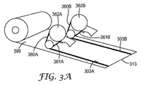
ガス拡散層の微多孔層を除去して、拡散層付着のための接着剤を添加するために、次の工程を用いた。図3Aを参照すると、微多孔層399は、ガス拡散層ロール品399の端の近くで除去される。ガス拡散層313から除去する微多孔層399の一部の除去は、従来のテープディスペンサ362A、362Bを用いた、接着剤転写テープ(3M Company(St.Paul、MN)製「SCOTCH ATG 700接着剤転写テープの商標名で入手可能)を使用して、チャネル303A、303Bを提供するのを容易にした。除去した微多孔層物質は、接着剤転写テープ内の廃棄ライナ361A、361Bの収集体へと巻き取られた。
Example 1
The following steps were used to remove the microporous layer of the gas diffusion layer and add an adhesive for diffusion layer adhesion. Referring to FIG. 3A, the
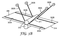
図3Bを参照すると、剥離ライナに25マイクロメートルの厚さでコーティングされている、被覆されたエチレンエチルアクリレートホットメルトフィルム363A、363B(Dow Chemical Co.(Midland、MI)製「DOW EA102」の商標名で入手した樹脂によって作製される)が、チャネル303A、303Bに充填するインプットホットメルト接着テープとして使われた。ホットメルト接着剤(図示せず、ローラ370間)を、ホットニップ371を使用して130℃で積層した。剥離ライナ365A、365Bを剥がした。
Referring to FIG. 3B, a coated ethylene ethyl acrylate hot melt film 363A, 363B ("DOW EA102" trademark from Dow Chemical Co. (Midland, MI) coated on a release liner with a thickness of 25 micrometers. Was used as an input hot melt adhesive tape to fill the
得られたガス拡散層(接着剤303A、303Bを備える)314はダイカットされており、その結果、接着剤303A、303Bの端レーンが触媒被覆膜16(図2を参照)の端に適合する。ガス拡散層14及びガス拡散層18(図2及び図2Aを参照)(ガス拡散層314が使用される)は、その後CCM16(図2を参照)に整列配置されて、従来のプレスで触媒被覆膜16(図2を参照)に熱結合されて、触媒被覆膜16(図2を参照)を形成した。
The resulting gas diffusion layer (comprising
本開示の予測可能な修正及び変更は、本発明の範囲及び趣旨から逸脱することなく、当業者には明らかであろう。本発明は、説明を目的として本出願に記載される実施形態に限定されるものではない。 Predictable modifications and variations of the present disclosure will be apparent to those skilled in the art without departing from the scope and spirit of the invention. The present invention is not limited to the embodiments described in this application for purposes of illustration.
Claims (16)
膜電極接合体の主表面上に第1の微多孔層を有する第1のガス拡散層を提供することであって、前記第1の微多孔層が主表面領域を有する、ことと、
前記第1のガス拡散層から前記第1の微多孔層の一部を除去して、第1の微多孔性物質を実質的に含まない前記第1のガス拡散層の主表面上に少なくとも第1の領域を提供することと、
第1及び第2の概して対向する主表面を有する触媒被覆膜を提供することであって、前記第1主表面がアノード触媒を含み、前記第2主表面がカソード触媒を含む、ことと、
前記第1のガス拡散層を前記触媒被覆膜の前記アノード触媒に固着することであって、前記第1のガス拡散層と前記触媒被覆膜とが共に結合するのを少なくとも部分的に助ける、前記第1の微多孔性物質を実質的に含まない、前記第1のガス拡散層の第1の領域の少なくとも一部に配設された第1の接着剤がある、ことと、
第2のガス拡散層を前記触媒被覆膜の前記カソード触媒に固着して、
前記膜電極接合体を提供することと、を含む、方法。 A method for producing a membrane electrode assembly, the method comprising:
Providing a first gas diffusion layer having a first microporous layer on a main surface of a membrane electrode assembly, wherein the first microporous layer has a main surface region;
A part of the first microporous layer is removed from the first gas diffusion layer, and at least a first surface on the main surface of the first gas diffusion layer substantially free of the first microporous material is removed. Providing one area,
Providing a catalyst-coated membrane having first and second generally opposing major surfaces, wherein the first major surface comprises an anode catalyst and the second major surface comprises a cathode catalyst;
Fixing the first gas diffusion layer to the anode catalyst of the catalyst coated membrane, at least partially helping the first gas diffusion layer and the catalyst coated membrane to bond together. There is a first adhesive disposed in at least a portion of the first region of the first gas diffusion layer that is substantially free of the first microporous material;
Fixing a second gas diffusion layer to the cathode catalyst of the catalyst-coated membrane;
Providing the membrane electrode assembly.
前記第2のガス拡散層から前記第2の微多孔層の一部を除去して、第2の微多孔性物質を実質的に含まない前記第2のガス拡散層の主表面上に少なくとも第1の領域を提供することと、
前記第2のガス拡散層を前記触媒被覆膜の前記カソード触媒に固着することであって、前記第2のガス拡散層と前記触媒被覆膜とが共に結合するのを少なくとも部分的に助ける、第2の微多孔性物質を実質的に含まない、前記第2のガス拡散層の前記第1の領域の少なくとも一部に配設された第2の接着剤がある、ことと、
によって、前記触媒被覆膜の前記カソード触媒に固着されている、請求項6〜10のいずれか一項に記載の方法。 The second gas diffusion layer has a second microporous layer on its main surface, the second microporous layer has a main surface region, and the second gas diffusion layer has at least ,
A part of the second microporous layer is removed from the second gas diffusion layer, and at least a second surface of the second gas diffusion layer substantially free of the second microporous material is formed. Providing one area,
Securing the second gas diffusion layer to the cathode catalyst of the catalyst coated membrane, at least partially assisting the bonding of the second gas diffusion layer and the catalyst coated membrane together. There is a second adhesive disposed in at least a portion of the first region of the second gas diffusion layer that is substantially free of a second microporous material;
The method according to any one of claims 6 to 10, wherein the catalyst-coated membrane is fixed to the cathode catalyst.
少なくとも1つのマスクを用いて、その主表面上の第1のガス拡散層上へ微多孔層をコーティングして、その主表面上に第1の微多孔層を有する第1のガス拡散層を提供することであって、前記第1の微多孔層が主表面を有し、前記第1の微多孔層の前記主表面がその内部に第1の微多孔性物質を実質的に含まない不連続領域を有し、少なくとも1つの不連続な領域の一部が前記第1のガス拡散層の作用面積にある、ことと、
第1及び第2の概して対向する主表面を有する触媒被覆膜を提供することであって、前記第1主表面がアノード触媒を含み、前記第2主表面がカソード触媒を含む、ことと、
前記第1のガス拡散層を前記触媒被覆膜の前記アノード触媒に固着することであって、前記第1のガス拡散層と前記触媒被覆膜とが共に結合するのを少なくとも部分的に助ける、前記第1の微多孔性物質を実質的に含まない、前記第1のガス拡散層の第1の領域の少なくとも一部に配設された第1の接着剤がある、ことと、
第2のガス拡散層を前記触媒被覆膜の前記カソード触媒に固着して、
前記膜電極接合体を提供することと、を含む、方法。 A method for producing a membrane electrode assembly, the method comprising:
Coating the microporous layer on the first gas diffusion layer on the major surface using at least one mask to provide a first gas diffusion layer having the first microporous layer on the major surface The first microporous layer has a main surface, and the main surface of the first microporous layer is discontinuous substantially free of the first microporous material therein. Having a region, and at least a part of the discontinuous region is in the active area of the first gas diffusion layer;
Providing a catalyst-coated membrane having first and second generally opposing major surfaces, wherein the first major surface comprises an anode catalyst and the second major surface comprises a cathode catalyst;
Fixing the first gas diffusion layer to the anode catalyst of the catalyst coated membrane, at least partially helping the first gas diffusion layer and the catalyst coated membrane to bond together. There is a first adhesive disposed in at least a portion of the first region of the first gas diffusion layer that is substantially free of the first microporous material;
Fixing a second gas diffusion layer to the cathode catalyst of the catalyst-coated membrane;
Providing the membrane electrode assembly.
Applications Claiming Priority (3)
| Application Number | Priority Date | Filing Date | Title |
|---|---|---|---|
| US201361917135P | 2013-12-17 | 2013-12-17 | |
| US61/917,135 | 2013-12-17 | ||
| PCT/US2014/069475 WO2015094845A1 (en) | 2013-12-17 | 2014-12-10 | Membrane electrode assembly and methods of making the same |
Publications (2)
| Publication Number | Publication Date |
|---|---|
| JP2017501544A true JP2017501544A (en) | 2017-01-12 |
| JP2017501544A5 JP2017501544A5 (en) | 2018-01-25 |
Family
ID=52293201
Family Applications (1)
| Application Number | Title | Priority Date | Filing Date |
|---|---|---|---|
| JP2016541357A Ceased JP2017501544A (en) | 2013-12-17 | 2014-12-10 | Membrane electrode assembly and manufacturing method thereof |
Country Status (7)
| Country | Link |
|---|---|
| US (1) | US10361441B2 (en) |
| EP (1) | EP3084858A1 (en) |
| JP (1) | JP2017501544A (en) |
| KR (1) | KR20160099598A (en) |
| CN (1) | CN105849934A (en) |
| CA (1) | CA2934256A1 (en) |
| WO (1) | WO2015094845A1 (en) |
Families Citing this family (1)
| Publication number | Priority date | Publication date | Assignee | Title |
|---|---|---|---|---|
| EP3472885A4 (en) * | 2016-06-15 | 2020-06-17 | 3M Innovative Properties Company | Membrane electrode assembly component and method of making an assembly |
Citations (1)
| Publication number | Priority date | Publication date | Assignee | Title |
|---|---|---|---|---|
| JP2007066769A (en) * | 2005-08-31 | 2007-03-15 | Nissan Motor Co Ltd | Electrolyte membrane-electrode assembly and its manufacturing method |
Family Cites Families (24)
| Publication number | Priority date | Publication date | Assignee | Title |
|---|---|---|---|---|
| JP4386740B2 (en) * | 2002-03-27 | 2009-12-16 | ダーレン・ジョーンズ | Cloth accessories |
| US8007949B2 (en) | 2002-10-08 | 2011-08-30 | Bhaskar Sompalli | Edge-protected catalyst-coated diffusion media and membrane electrode assemblies |
| US20040116742A1 (en) | 2002-12-17 | 2004-06-17 | 3M Innovative Properties Company | Selective reaction of hexafluoropropylene oxide with perfluoroacyl fluorides |
| US6624328B1 (en) | 2002-12-17 | 2003-09-23 | 3M Innovative Properties Company | Preparation of perfluorinated vinyl ethers having a sulfonyl fluoride end-group |
| US7348088B2 (en) | 2002-12-19 | 2008-03-25 | 3M Innovative Properties Company | Polymer electrolyte membrane |
| US20060188773A1 (en) | 2003-03-25 | 2006-08-24 | Peter Andrin | Process for joining a gas diffusion layer to a separator plate |
| GB0319780D0 (en) * | 2003-08-22 | 2003-09-24 | Johnson Matthey Plc | Membrane electrode assembly |
| US20050064275A1 (en) | 2003-09-18 | 2005-03-24 | 3M Innovative Properties Company | Fuel cell gas diffusion layer |
| CA2539602C (en) * | 2003-09-20 | 2013-10-29 | Heiko Oschmann | Catalyst-coated membrane with integrated sealing material and membrane-electrode assembly produced therefrom |
| US20060127738A1 (en) | 2004-12-13 | 2006-06-15 | Bhaskar Sompalli | Design, method and process for unitized mea |
| JP5326185B2 (en) * | 2005-09-28 | 2013-10-30 | 日産自動車株式会社 | Gas diffusion electrode material and manufacturing method thereof |
| DE102006004748A1 (en) | 2006-02-02 | 2007-08-16 | Umicore Ag & Co. Kg | Membrane electrode unit with multi-component sealing edge |
| US7413826B2 (en) | 2006-02-16 | 2008-08-19 | Matsushita Electric Industrial Co., Ltd. | Anode electrodes for direct oxidation fuel cells and systems operating with concentrated liquid fuel |
| CN101106264B (en) * | 2006-07-14 | 2010-12-22 | 鸿富锦精密工业(深圳)有限公司 | Waterproof automatic protection device of electronic device |
| CN101553946A (en) * | 2006-10-02 | 2009-10-07 | 巴斯夫欧洲公司 | Method for the production of a membrane electrode unit |
| US9172106B2 (en) * | 2006-11-09 | 2015-10-27 | GM Global Technology Operations LLC | Fuel cell microporous layer with microchannels |
| US8288059B2 (en) | 2006-12-15 | 2012-10-16 | 3M Innovative Properties Company | Processing methods and systems for assembling fuel cell perimeter gaskets |
| TWI334237B (en) | 2007-01-05 | 2010-12-01 | Ind Tech Res Inst | Gas diffusion layer, manufacturing apparatus and manufacturing method thereof |
| US20080206615A1 (en) | 2007-02-22 | 2008-08-28 | Paul Nicotera | Gas diffusion layer with controlled diffusivity over active area |
| GB0718620D0 (en) | 2007-09-25 | 2007-10-31 | Johnson Matthey Plc | Membrane electrode assembly |
| JP2009245848A (en) * | 2008-03-31 | 2009-10-22 | Toshiba Corp | Fuel cell system |
| KR20100004495A (en) | 2008-07-04 | 2010-01-13 | 현대자동차주식회사 | Method for bonding mea and gdl of fuel cell stack |
| JP5614462B2 (en) | 2011-12-26 | 2014-10-29 | 東レ株式会社 | Gas diffusion electrode base material for fuel cell, membrane electrode assembly, and fuel cell |
| WO2015095021A1 (en) | 2013-12-17 | 2015-06-25 | 3M Innovative Properties Company | Membrane electrode assembly and methods of making the same |
-
2014
- 2014-12-10 WO PCT/US2014/069475 patent/WO2015094845A1/en active Application Filing
- 2014-12-10 US US15/105,170 patent/US10361441B2/en not_active Expired - Fee Related
- 2014-12-10 JP JP2016541357A patent/JP2017501544A/en not_active Ceased
- 2014-12-10 KR KR1020167018096A patent/KR20160099598A/en not_active Application Discontinuation
- 2014-12-10 CA CA2934256A patent/CA2934256A1/en not_active Abandoned
- 2014-12-10 CN CN201480069221.2A patent/CN105849934A/en active Pending
- 2014-12-10 EP EP14824639.0A patent/EP3084858A1/en not_active Withdrawn
Patent Citations (1)
| Publication number | Priority date | Publication date | Assignee | Title |
|---|---|---|---|---|
| JP2007066769A (en) * | 2005-08-31 | 2007-03-15 | Nissan Motor Co Ltd | Electrolyte membrane-electrode assembly and its manufacturing method |
Also Published As
| Publication number | Publication date |
|---|---|
| CN105849934A (en) | 2016-08-10 |
| CA2934256A1 (en) | 2015-06-25 |
| US10361441B2 (en) | 2019-07-23 |
| KR20160099598A (en) | 2016-08-22 |
| WO2015094845A1 (en) | 2015-06-25 |
| US20160322651A1 (en) | 2016-11-03 |
| EP3084858A1 (en) | 2016-10-26 |
Similar Documents
| Publication | Publication Date | Title |
|---|---|---|
| JP5107050B2 (en) | Manufacturing method of membrane electrode assembly for polymer electrolyte fuel cell | |
| JP4699763B2 (en) | One-step method for joining and sealing fuel cell membrane electrode assemblies | |
| JP5208773B2 (en) | Method for producing membrane electrode assembly for polymer electrolyte fuel cell and method for producing polymer electrolyte fuel cell | |
| JP5397228B2 (en) | Manufacturing method of membrane electrode assembly for polymer electrolyte fuel cell | |
| US9406940B2 (en) | Conductive porous layer for batteries and fabrication method for same | |
| JP5298469B2 (en) | Gas diffusion electrode for fuel cell | |
| JP4348155B2 (en) | Catalyst membrane for polymer electrolyte fuel cell, production method thereof and fuel cell using the same | |
| JP4301397B2 (en) | Membrane electrode assembly for fuel cell and method for producing the same | |
| JP6911847B2 (en) | Manufacturing method of gas diffusion electrode base material | |
| CN112909291A (en) | Preparation method of membrane electrode, membrane electrode and fuel cell | |
| JP6251737B2 (en) | Base material for gas diffusion electrode | |
| JP2019083113A (en) | Electrode catalyst layer, membrane electrode assembly, and solid polymer fuel cell | |
| JP2017501544A (en) | Membrane electrode assembly and manufacturing method thereof | |
| WO2015095021A1 (en) | Membrane electrode assembly and methods of making the same | |
| JP4348154B2 (en) | Catalyst membrane for polymer electrolyte fuel cell, production method thereof and fuel cell using the same | |
| JP6952543B2 (en) | Membrane electrode assembly, electrochemical cell, stack, fuel cell and vehicle | |
| JP6009252B2 (en) | Moisture management sheet, gas diffusion sheet, membrane-electrode assembly, and polymer electrolyte fuel cell | |
| JP6775346B2 (en) | Membrane-conductive porous sheet joints and polymer electrolyte fuel cells | |
| JP6775316B2 (en) | Membrane-electrode assembly and polymer electrolyte fuel cell | |
| JP2015171668A (en) | gas permeable sheet | |
| JP2008243683A (en) | Porous conductive substrate, gas diffusion electrode, membrane-electrode assembly, and fuel cell | |
| JP2012074319A (en) | Moisture control sheet, gas diffusion sheet, membrane-electrode assembly and solid polymer fuel cell | |
| JP2005166473A (en) | Electrode for fuel cell |
Legal Events
| Date | Code | Title | Description |
|---|---|---|---|
| RD03 | Notification of appointment of power of attorney |
Free format text: JAPANESE INTERMEDIATE CODE: A7423 Effective date: 20170907 |
|
| RD04 | Notification of resignation of power of attorney |
Free format text: JAPANESE INTERMEDIATE CODE: A7424 Effective date: 20170912 |
|
| A521 | Request for written amendment filed |
Free format text: JAPANESE INTERMEDIATE CODE: A523 Effective date: 20171207 |
|
| A621 | Written request for application examination |
Free format text: JAPANESE INTERMEDIATE CODE: A621 Effective date: 20171207 |
|
| A131 | Notification of reasons for refusal |
Free format text: JAPANESE INTERMEDIATE CODE: A131 Effective date: 20190108 |
|
| A601 | Written request for extension of time |
Free format text: JAPANESE INTERMEDIATE CODE: A601 Effective date: 20190405 |
|
| A521 | Request for written amendment filed |
Free format text: JAPANESE INTERMEDIATE CODE: A523 Effective date: 20190607 |
|
| A01 | Written decision to grant a patent or to grant a registration (utility model) |
Free format text: JAPANESE INTERMEDIATE CODE: A01 Effective date: 20191203 |
|
| A045 | Written measure of dismissal of application [lapsed due to lack of payment] |
Free format text: JAPANESE INTERMEDIATE CODE: A045 Effective date: 20200630 |