JP2017500722A - Workpiece transfer and placement device - Google Patents
Workpiece transfer and placement device Download PDFInfo
- Publication number
- JP2017500722A JP2017500722A JP2016553269A JP2016553269A JP2017500722A JP 2017500722 A JP2017500722 A JP 2017500722A JP 2016553269 A JP2016553269 A JP 2016553269A JP 2016553269 A JP2016553269 A JP 2016553269A JP 2017500722 A JP2017500722 A JP 2017500722A
- Authority
- JP
- Japan
- Prior art keywords
- workpiece
- sample
- grid
- holder
- automated
- Prior art date
- Legal status (The legal status is an assumption and is not a legal conclusion. Google has not performed a legal analysis and makes no representation as to the accuracy of the status listed.)
- Pending
Links
Images


Classifications
-
- H—ELECTRICITY
- H01—ELECTRIC ELEMENTS
- H01J—ELECTRIC DISCHARGE TUBES OR DISCHARGE LAMPS
- H01J37/00—Discharge tubes with provision for introducing objects or material to be exposed to the discharge, e.g. for the purpose of examination or processing thereof
- H01J37/02—Details
- H01J37/20—Means for supporting or positioning the objects or the material; Means for adjusting diaphragms or lenses associated with the support
-
- G—PHYSICS
- G01—MEASURING; TESTING
- G01N—INVESTIGATING OR ANALYSING MATERIALS BY DETERMINING THEIR CHEMICAL OR PHYSICAL PROPERTIES
- G01N35/00—Automatic analysis not limited to methods or materials provided for in any single one of groups G01N1/00 - G01N33/00; Handling materials therefor
- G01N35/00584—Control arrangements for automatic analysers
- G01N35/00722—Communications; Identification
- G01N35/00732—Identification of carriers, materials or components in automatic analysers
-
- H—ELECTRICITY
- H01—ELECTRIC ELEMENTS
- H01J—ELECTRIC DISCHARGE TUBES OR DISCHARGE LAMPS
- H01J37/00—Discharge tubes with provision for introducing objects or material to be exposed to the discharge, e.g. for the purpose of examination or processing thereof
- H01J37/02—Details
- H01J37/023—Means for mechanically adjusting components not otherwise provided for
-
- H—ELECTRICITY
- H01—ELECTRIC ELEMENTS
- H01J—ELECTRIC DISCHARGE TUBES OR DISCHARGE LAMPS
- H01J37/00—Discharge tubes with provision for introducing objects or material to be exposed to the discharge, e.g. for the purpose of examination or processing thereof
- H01J37/02—Details
- H01J37/18—Vacuum locks ; Means for obtaining or maintaining the desired pressure within the vessel
- H01J37/185—Means for transferring objects between different enclosures of different pressure or atmosphere
-
- H—ELECTRICITY
- H01—ELECTRIC ELEMENTS
- H01J—ELECTRIC DISCHARGE TUBES OR DISCHARGE LAMPS
- H01J37/00—Discharge tubes with provision for introducing objects or material to be exposed to the discharge, e.g. for the purpose of examination or processing thereof
- H01J37/26—Electron or ion microscopes; Electron or ion diffraction tubes
- H01J37/261—Details
-
- G—PHYSICS
- G01—MEASURING; TESTING
- G01N—INVESTIGATING OR ANALYSING MATERIALS BY DETERMINING THEIR CHEMICAL OR PHYSICAL PROPERTIES
- G01N1/00—Sampling; Preparing specimens for investigation
- G01N1/28—Preparing specimens for investigation including physical details of (bio-)chemical methods covered elsewhere, e.g. G01N33/50, C12Q
- G01N1/32—Polishing; Etching
-
- H—ELECTRICITY
- H01—ELECTRIC ELEMENTS
- H01J—ELECTRIC DISCHARGE TUBES OR DISCHARGE LAMPS
- H01J2237/00—Discharge tubes exposing object to beam, e.g. for analysis treatment, etching, imaging
- H01J2237/20—Positioning, supporting, modifying or maintaining the physical state of objects being observed or treated
- H01J2237/2007—Holding mechanisms
-
- H—ELECTRICITY
- H01—ELECTRIC ELEMENTS
- H01J—ELECTRIC DISCHARGE TUBES OR DISCHARGE LAMPS
- H01J2237/00—Discharge tubes exposing object to beam, e.g. for analysis treatment, etching, imaging
- H01J2237/20—Positioning, supporting, modifying or maintaining the physical state of objects being observed or treated
- H01J2237/201—Positioning, supporting, modifying or maintaining the physical state of objects being observed or treated for mounting multiple objects
-
- H—ELECTRICITY
- H01—ELECTRIC ELEMENTS
- H01J—ELECTRIC DISCHARGE TUBES OR DISCHARGE LAMPS
- H01J2237/00—Discharge tubes exposing object to beam, e.g. for analysis treatment, etching, imaging
- H01J2237/20—Positioning, supporting, modifying or maintaining the physical state of objects being observed or treated
- H01J2237/202—Movement
- H01J2237/20278—Motorised movement
- H01J2237/20285—Motorised movement computer-controlled
-
- H—ELECTRICITY
- H01—ELECTRIC ELEMENTS
- H01J—ELECTRIC DISCHARGE TUBES OR DISCHARGE LAMPS
- H01J2237/00—Discharge tubes exposing object to beam, e.g. for analysis treatment, etching, imaging
- H01J2237/20—Positioning, supporting, modifying or maintaining the physical state of objects being observed or treated
- H01J2237/202—Movement
- H01J2237/20292—Means for position and/or orientation registration
-
- H—ELECTRICITY
- H01—ELECTRIC ELEMENTS
- H01J—ELECTRIC DISCHARGE TUBES OR DISCHARGE LAMPS
- H01J2237/00—Discharge tubes exposing object to beam, e.g. for analysis treatment, etching, imaging
- H01J2237/20—Positioning, supporting, modifying or maintaining the physical state of objects being observed or treated
- H01J2237/204—Means for introducing and/or outputting objects
-
- H—ELECTRICITY
- H01—ELECTRIC ELEMENTS
- H01J—ELECTRIC DISCHARGE TUBES OR DISCHARGE LAMPS
- H01J2237/00—Discharge tubes exposing object to beam, e.g. for analysis treatment, etching, imaging
- H01J2237/26—Electron or ion microscopes
-
- H—ELECTRICITY
- H01—ELECTRIC ELEMENTS
- H01J—ELECTRIC DISCHARGE TUBES OR DISCHARGE LAMPS
- H01J2237/00—Discharge tubes exposing object to beam, e.g. for analysis treatment, etching, imaging
- H01J2237/26—Electron or ion microscopes
- H01J2237/2602—Details
Landscapes
- Chemical & Material Sciences (AREA)
- Analytical Chemistry (AREA)
- Physics & Mathematics (AREA)
- Health & Medical Sciences (AREA)
- Life Sciences & Earth Sciences (AREA)
- Biochemistry (AREA)
- General Health & Medical Sciences (AREA)
- General Physics & Mathematics (AREA)
- Immunology (AREA)
- Pathology (AREA)
- Container, Conveyance, Adherence, Positioning, Of Wafer (AREA)
- Sampling And Sample Adjustment (AREA)
- Analysing Materials By The Use Of Radiation (AREA)
- Engineering & Computer Science (AREA)
- Mechanical Engineering (AREA)
Abstract
自動化ワークピース処理装置は、処理位置でワークピースを処理するように構成される処理モジュールを含む処理セクションと、多段シャトルを含む搬送モジュールであって、多段シャトルは複数の動作自由度を有する第1のシャトルステージと、第1のステージから独立した複数の動作自由度を有する第2のシャトルステージとを有する搬送モジュールと、第1および第2のシャトルステージの少なくとも一方に接続されるエンドエフェクタとを含み、エンドエフェクタは、ワークピースを保持し、処理モジュール内および処理モジュール外へワークピースを搬送するように構成され、またエンドエフェクタは、処理位置でワークピースを配置するために、処理モジュール外部のワークピース保持ステーションから処理モジュール内部の処理位置まで延びる、第1および第2のステージの複数の動作自由度の組み合わせにより定められる動作範囲を有するので、処理モジュールの処理ステージを定める搬送モジュールと、自動化装着および搬送セクションであって、ワークピースが自動化装着および搬送セクション内に装着されるロードポートモジュールを含み、搬送モジュールに連通可能に接続されている自動化装着および搬送セクションとを含む。The automated workpiece processing apparatus includes a processing section including a processing module configured to process a workpiece at a processing position, and a transfer module including a multi-stage shuttle, wherein the multi-stage shuttle has a plurality of degrees of freedom of operation. A transport module having a second shuttle stage having a plurality of degrees of freedom independent of the first stage, and an end effector connected to at least one of the first and second shuttle stages. And the end effector is configured to hold the workpiece and transport the workpiece into and out of the processing module, and the end effector is external to the processing module to place the workpiece in the processing position. Processing inside the processing module from the workpiece holding station A transfer module defining a processing stage of a processing module and an automated mounting and transfer section, having an operating range defined by a combination of a plurality of operating degrees of freedom of the first and second stages extending to a position, Includes a load port module mounted in the automated mounting and transport section, and includes an automated mounting and transport section communicatively connected to the transport module.
Description
[関連出願の相互参照]
本願は、2013年11月11日に出願された米国仮特許出願第61/902,470号明細書の非仮特許出願であり、この出願の利益を主張し、開示内容はその全体を参照することによって本明細書に含まれる。
[Cross-reference of related applications]
This application is a non-provisional patent application of US Provisional Patent Application No. 61 / 902,470, filed on November 11, 2013, and claims the benefit of this application, the disclosure of which is incorporated by reference in its entirety Are included herein.
1.分野
例示的な実施形態は、大まかには自動化ワークピース処理システムに関し、より詳細には、自動化処理システムのための自動装着システムに関する。
1. FIELD Exemplary embodiments relate generally to an automated workpiece processing system, and more particularly to an automatic loading system for an automated processing system.
2.関連する開発の簡単な説明
一般に、自動化ワークピース処理システムは、ワークピース搬送部と処理モジュールとを含む。ワークピース搬送部は、一般に、ワークピースが処理のためにワークピースホルダ上に配置される処理モジュールへ、および処理モジュールから、ワークピースを搬送するために用いられている。ワークピースの処理中、搬送部は処理モジュールから取り外され、処理モジュールは一般には密閉される。
2. BRIEF DESCRIPTION OF RELATED DEVELOPMENT Generally, an automated workpiece processing system includes a workpiece transport and a processing module. The workpiece transport is typically used to transport workpieces to and from a processing module where the workpiece is placed on a workpiece holder for processing. During processing of the workpiece, the transport section is removed from the processing module and the processing module is typically sealed.
処理モジュールのワークピースホルダのいくつかは、処理のためにワークピースを配置するように構成される可動ステージを含む。これらの可動ステージ、ならびにワークピースを処理モジュールに運ぶ搬送部は、処理中にワークピースの望ましくない振動モードが存在しないよう、ワークピースの残りの動作を弱まらせるように、一般にはワークピースの移動の間に整定時間を要する。 Some of the workpiece holders in the processing module include a movable stage configured to place the workpiece for processing. These movable stages, as well as the transport that transports the workpiece to the processing module, are generally workpieces so as to damp the rest of the workpiece movement so that there are no undesirable vibration modes of the workpiece during processing. It takes a settling time between the movements.
ワークピースを処理モジュールに運び、ワークピースの処理中にワークピースを処理モジュール内に配置することができるワークピース搬送部を含む、自動化搬送および配置システムを有することが有利である。 It would be advantageous to have an automated transport and placement system that includes a workpiece transport that can carry the workpiece to the processing module and place the workpiece within the processing module during processing of the workpiece.
一般に、従来のワークピースはサンプル/試料を保持するように構成されている。従来のワークピースは、番号などの単純な識別マーキングを有するが、これらの単純な識別マーキングは範囲が限定され、固有の識別子となる保証はない。このように、従来のワークピースにより保持される多数のサンプルを追跡することは、ひいき目に見ても困難である。 In general, conventional workpieces are configured to hold a sample / specimen. Conventional workpieces have simple identification markings, such as numbers, but these simple identification markings are limited in scope and are not guaranteed to be unique identifiers. Thus, it is difficult to track a large number of samples held by a conventional workpiece, even at the eye.
一般にワークピースはワークピースホルダに保管される。これらのワークピースホルダは一般にはワークピースの保持容量が小さく、また最大の超低温ワークピース処理システムを除いて、ワークピース処理システム内に自動的に装着される機能は提供しない。 In general, the workpiece is stored in a workpiece holder. These workpiece holders generally have a small workpiece holding capacity and do not provide the ability to be automatically loaded into the workpiece processing system, except for the largest cryogenic workpiece processing system.
固有に識別可能で、手動または自動で操作され得るワークピースを有することが有利である。ワークピースにより保持されるサンプルのバッチ処理ならびにサンプルの追跡を可能にするワークピース処理システムへの、手動および/または自動の装着が可能な高容量のワークピース保持システムを有することが有利である。 It is advantageous to have a workpiece that is uniquely identifiable and can be operated manually or automatically. It would be advantageous to have a high capacity workpiece holding system that can be manually and / or automatically loaded into a workpiece processing system that allows batch processing of samples held by the workpiece and tracking of the sample.
また、従来の、電子光線撮像/走査ワークステーションなどのワークピース処理システムは、構造体(複数の試料/サンプルに分割される)の処理中に、その構造体の経過を自動的に追跡する能力を有さない。 Also, conventional workpiece processing systems, such as electron beam imaging / scanning workstations, are capable of automatically tracking the progress of the structure during processing of the structure (divided into multiple specimens / samples). Does not have.
分析されている構造体に関して、処理中に複数の試料を全体として追跡および分析できることが有利である。 With respect to the structure being analyzed, it is advantageous to be able to track and analyze multiple samples as a whole during processing.
開示される実施形態の上述の態様および他の特徴は、添付の図面と関連して以下の記載において説明される。 The foregoing aspects and other features of the disclosed embodiments are described in the following description in conjunction with the accompanying drawings.
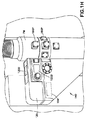
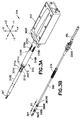
図1は、開示される実施形態の態様による自動化搬送および配置システム100の概略図である。開示される実施形態の態様は、図面に関連して説明されるが、開示される実施形態の態様は、多くの形態で具体化され得ることが理解されるべきである。加えて、任意の適切なサイズ、形状、または種類の、構成要素または材料が使用され得る。また、X、YおよびZ軸が参照されているが、これらの軸への参照は例示的であり、別の態様において軸は、任意の適切な方向識別子を有することに留意する。
FIG. 1 is a schematic diagram of an automated transport and
また、開示される実施形態の態様は、本明細書においては透過型電子顕微鏡(TEM)に関して記載されるが、開示される実施形態の態様は、走査電子顕微鏡(SEM)、デュアル光線集束イオン光線顕微鏡(DB−FIB)、走査透過型顕微鏡(STEM)、他の任意の適切な電子光線走査/撮像装置、または、ワークピースの処理の間、ワークピースがステージまたはエンドエフェクタ(本明細書に記載)のワークピースホルダ上に支持される処理モジュールPMを有する任意の適切なワークピース処理装置に適用され得ることが理解されるべきである。例えば、開示される実施形態の態様は、測定/検査または他の処理の間、ワークピースが開示される実施形態のエンドエフェクタによって保持される任意の適切な測定装置に用いられる。以下に記載するように、一態様において、ステージは自動搬送および配置システム100のワークピース配置ユニット104のエンドエフェクタ101であるが、別の態様においてステージは、処理モジュールPMの既存の配置ステージPSである。
Also, although aspects of the disclosed embodiments are described herein with respect to a transmission electron microscope (TEM), aspects of the disclosed embodiments include a scanning electron microscope (SEM), dual beam focused ion beam During the processing of a workpiece (such as a microscope (DB-FIB), a scanning transmission microscope (STEM), any other suitable electron beam scanning / imaging device, or workpiece processing) It should be understood that it can be applied to any suitable workpiece processing apparatus having a processing module PM supported on a workpiece holder. For example, aspects of the disclosed embodiment may be used with any suitable measurement device where the workpiece is held by the end effector of the disclosed embodiment during measurement / inspection or other processing. As described below, in one aspect, the stage is the
一態様において、TEMに関して、自動化搬送および配置システム100は、一回の交換(例えば、試料の装着)において約500〜約1000の試料(本明細書においてはサンプルともいう)の装着および保管をもたらすが、TEMや他の適切なワークピース処理装置(上述のものなど)に関連付けられる他の態様においては、より多いまたはより少ないワークピースが装着および保管される。一態様において、自動化搬送および配置システム100は、例えば、撮像の間、試料ホルダまたはグリッドをTEM内で配置するTEMにおいて用いられる、従来の配置「ステージ」PSに取って代わる。別の態様において、自動化搬送および配置システム100は、例えば、任意の適切な測定装置または他の処理装置の、任意の適切な装着システムに取って代わる。一態様において、自動化搬送および配置システム100は、撮像または検査中の、ワークピースの完全で高解像度の、高速、高安定の位置制御も提供する。以下に記載するように、開示される実施形態の態様にしたがって、グリッド操作および保管動作、ならびにTEMカラムへの試料の配置は、一態様においては、制御された8自由度を用いてもたらされ、別の態様においては、制御された9自由度を用いてもたらされる。
In one aspect, with respect to TEM, the automated transport and
また以下に記載するように、自動化搬送および配置システム100は、例えば、ワークピースを操作システムに結合させるキャリアまたはアダプタを用いて、または用いずに、グリッド(または他の適切な試料ホルダ)などの任意の適切なワークピース400を実質的に直接操作するように構成されるエンドエフェクタ101を有する搬送および配置ユニット140を含む。一態様においてエンドエフェクタ101のグリッパは、一態様においては8つの制御された自由度の2以上、別の態様においては制御された9自由度の連係動作を通して操作され、これらは組み合わせられると、ワークピースに対してエンドエフェクタの位置を一定に維持したままグリッパを開閉するように作用し、またエンドエフェクタ101の複数の独立した自由度の動作をもたらす。別の態様において、エンドエフェクタのグリッパは、グリッパを駆動する専用の駆動部を用いるなど、任意の適切な方法で操作される。一態様において、エンドエフェクタ101は、電子顕微鏡システムの対物レンズチャンバ(後述)内などの高真空環境において、または非真空や低真空環境などの他の任意の適切な環境において、ワークピースを操作するように構成される。エンドエフェクタ101は、任意の適切なワークピース保持カセット102からの抜き取りの間、個別のワークピースを把持するように構成され、また、ワークピースの回転による位置合わせのためのプリアライナステージ103への、およびプリアライナ103からの、ワークピースの設置および除去のためにも構成される。一態様において、エンドエフェクタ101(およびエンドエフェクタがその一部であるワークピース配置ユニットまたは多段シャトル104)は、グリッドに取り付けられた試料を支持するための精密かつ堅固なインターフェースを提供するように構成され、これは、撮像中にワークピースの望ましくない振動モードを実質的に導くことなく、約100ms未満で、高速な位置の移動(例えば、約8〜約24ミクロンまたは他の任意の適切な距離)および迅速な整定(例えば、約5ナノメータ未満まで)を可能にする。別の態様において、エンドエフェクタ101(およびエンドエフェクタがその一部であるワークピース配置ユニット104)は、撮像中にワークピースの望ましくない振動モードを実質的に導くことなく、約25ms〜約35ms未満で、高速な位置の移動(例えば、約8〜約24ミクロンまたは他の任意の適切な距離)および迅速な整定(例えば、約4ナノメータ未満まで)を実施するように構成され得る。エンドエフェクタ101は、単一のワークピース保持グリッパを有するものとして示されているが、別の態様においてエンドエフェクタは、例えば、隣り合う配置や他の任意の適切な配置で、複数のワークピースを保持するように構成されることに留意する。後述するように、自動化搬送および配置システム100は、これに限定されないが薄片のトモグラフィーを含む、処理モジュール内でのサンプルの任意の適切な処理をもたらすために、複数の自由度(一態様においては少なくとも3自由度)を有する駆動セクションを含む。一態様において、本明細書に記載されるように、自動搬送および配置システム100の駆動セクションの複数の自由度は、互いに対して傾斜される少なくとも2つの軸周りでの、少なくとも1つの線形の軸交差および回転を含む。一態様において、本明細書に記載される自動化搬送および配置システム100の駆動セクションは、エンドエフェクタ101を用いたワークピースの自動の取り出しをもたらすように構成される。一態様において、自動化搬送および配置システム100の駆動セクションは、ミクロンレベルの分解能(例えば、一態様においては約0.5ミクロン、別の態様においては約0.5ミクロンより大きいか、または小さい)でエンドエフェクタの動作をもたらし、別の、例えばトモグラフィー検査位置へと、約100ms未満で再び配置することをもたらす。
As also described below, the automated transport and
以下に記載されるように、一態様においてワークピースの操作(例えば、取り出しおよび配置)は、視覚システムを利用して、または、エンドエフェクタ101内に実質的に直接一体化され、および/または、ワークピースが本明細書に記載するように撮像される他の適切な場所ではエンドエフェクタから外される、1つまたは複数のカメラまたは光学検出器および/または照射ユニットを含む、他の適切な光学および/または無線周波数読み取り器を利用して行われる。一体型の視覚システムまたは他の適切な光学および/または無線周波数読み取り器は、ワークピース操作動作の実質的に継続した監視を提供し、自動化搬送および配置システム100に接続される任意の適切な制御装置199の任意の適切なメモリ199Mに保管される任意の適切な画像分析アルゴリズムを通して、各動作の閉ループ制御を許可する。一態様において、制御装置199は、自動化搬送および配置システム100から遠隔に位置付けられるが、別の態様において制御装置は、自動化搬送および配置システムに一体化される。制御装置199は、本明細書に記載される方法で自動化搬送および配置システムを制御するように適切に構成されることに留意する。一態様において、制御装置199は、検査室または本明細書に記載するような他の設備内の試料サンプルの場所を追跡するために、検査室情報管理システムLIMSに任意の適切な方法で接続されるか、または一体化される。視覚システムは、ワークピースの操作動作中にワークピースの位置合わせをもたらすために、ワークピースの基準(またはグリッドの他の適切な特徴部)の検出を提供する。別の態様において、視覚システムは、ワークピースの識別、追跡、および/または、エンドエフェクタの制御された従動動作をもたらすために提供される。
As described below, in one aspect, manipulation (e.g., removal and placement) of the workpiece is substantially integrated directly into the
一態様において、ワークピースまたはグリッド400は、カセット102などのバッチホルダに保持され、カセット102は、以下に記載されるように自動化搬送および配置システム100内への挿入のために構成される1つまたは複数のマガジン105などのバッチホルダに保持される。マガジン105およびその中のカセット102は、カセット102(および1つまたは複数のワークピース/試料、例えば、中に位置付けられるワークピース/試料のバッチ)の自動の装着および取り外しを提供するために構成される。例えば、マガジン105およびカセット102は、自動化搬送および配置システム100内および自動化搬送および配置システム100外部の自動化操作システムにより、マガジン105およびカセット102の実質的に直接的な操作(例えば、1つの単位として、または個別)を可能にする運動学的機構を含む。一態様において、マガジン105およびカセット102は、真空環境での使用のために構成されるが、別の態様においてマガジン105およびカセット102は、非真空環境での使用のために構成される。一態様において、カセット102およびマガジン105は、超低温環境または任意の適切な温度を有する他の任意の適切な環境での使用のために構成される。
In one aspect, workpiece or
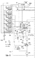
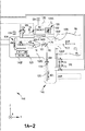
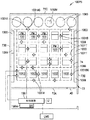
依然として図1Aを参照し、さらに図1B〜1Dを参照すると、自動化搬送および配置システム100は、フレーム140Fと、フレーム140Fに接続される搬送および配置ユニット140と、搬送および配置ユニット140に連通可能に連結される空気圧モジュール130(フレームに接続され得る)と、搬送および配置ユニット140に連通可能に連結される真空モジュール172(フレームに接続され得る)とを含む。一態様において、空気圧モジュール130は、例えば、搬送および配置ユニット140のバルブおよびクロージャ、および/または、本明細書に記載される真空モジュール172を動作させるために、空気源130Sと、任意の適切なバルブV1G、V2G、V3T、V4R、V5R、V6とを含む。真空モジュール172は、例えば、TEMまたは他の適切な処理モジュールPMと連動するために、任意の適切な真空圧で搬送および配置ユニット140の内部チャンバをポンプし、維持する、任意の適切な真空ポンプP1R、P2T、P3IおよびゲージG1R、G2H、G3H、G4Hを含む。一態様において、真空モジュール172は、例えば真空ポンプを、互いから、および/または搬送および配置ユニット140のチャンバから選択的に隔離するために、任意の適切なバルブV3T、V4R、V5R、V6、V7T、V8V、V9Vを含む。
Still referring to FIG. 1A, and with further reference to FIGS. 1B-1D, the automated transport and
一態様においてフレーム140Fは、搬送および配置ユニット140の少なくとも一部を形成するか、または少なくとも一部と一体である(例えば、一体ユニットの構成)。別の態様において、搬送および配置ユニット140は、任意の適切な方法でフレーム140Fに接続される。一態様において搬送および配置ユニット140は、密閉可能なチャンバ120Cを有する自動化装着および搬送セクションまたはロードロック120と、密閉可能な搬送チャンバ125Cを有する搬送モジュールまたはセクション125とを含む。チャンバ120Cは、閉鎖可能な開口またはポート120Pを通してチャンバ125Cに選択的に連通可能に接続される。一態様において、搬送および配置ユニット140は、チャンバ120Cの雰囲気を、チャンバ125Cの雰囲気から密閉あるいは隔離するためにポート120Pを選択的に密閉するように構成される任意の適切なゲートバルブV2Gを含む。ロードロック120は、ロードロック120の装着開口を密閉するように構成される任意の適切なドア120Dを含む。図面においては、単一のドア120Dが、チャンバ120Cの側面に位置付けられるものとして図示されているが、別の態様において、単一のドア120Dはチャンバ125Cの上面に位置付けられ(図1Dを参照、例えば、チャンバにおけるマガジン105の頭上での装着のために、ドアの自動化された開閉を可能にするため)、さらに別の態様においては、2つ以上のドア(例えば、上面および側面上、図1Hを参照)がチャンバ125へのアクセスを提供することが理解されるべきである。一態様においてドアは、ロードロック120にヒンジ接続されているが、別の態様においてドアは、チャンバ120Cへのアクセスを可能にするために、ロードロック120Dから取り外し可能である。一態様においてドア120Dは、手動の閉鎖部を有し、別の態様においてドア120Dは、自動化された閉鎖部を有する。別の態様においてチャンバ120Cは、チャンバ125C内の雰囲気が、例えば、カセットがチャンバ125Cに導入されるときおよびチャンバ125Cから除去されるときに、処理雰囲気と大気圧との間で循環されるように、ドアを含んでいない場合もある。装着開口は、1つまたは2つ以上のワークピースの、チャンバ120Cへの進入、およびチャンバ120Cからの退出を可能にするように構成される。一態様において、以下にさらに記載されるように、ワークピースは、カセット102、すなわちマガジン105により保持されるTEMグリッドである。一態様においてロードロックは、ポジショナーユニット120MSPを含む自動化搬送シャトル120MSを含む。ポジショナーユニット120MSPは、チャンバ120C内での搬送シャトル120MSの動作を可能にするために任意の適切なモータおよび/またはガイドを含み、真空また大気圧環境の1つまたは複数での動作のために構成される。ポジショナーユニット120MSPは、少なくともY軸に沿って搬送シャトル120MSを移動させるために、任意の適切な駆動部またはモータA1Lを含む。一態様においてモータA1Lは、約5μmという配置分解能で搬送シャトル120MSを配置するために、ねじ駆動部を駆動するDCステッパモータである。別の態様においてモータは、ピエゾモータ、ブラシレスモータまたはブラシモータなど、任意の適切な配置分解能を有する任意の適切なモータである。搬送シャトル120MSは、1つまたは複数のマガジン105を保持し、マガジンをXおよびY方向の1つまたは複数に搬送するか、あるいは移動させる(例えば、ポジショナーユニット120MSPを介して)ように構成されるので、所定のカセット102は、以下に記載されるようにチャンバ125C内への搬送のためにポート120Pと位置合わせされる。搬送シャトル120MSは、マガジン105を搬送シャトル120MSに対して配置するために、マガジン105の対応する運動学的機構(後述)と嵌合する任意の適切な運動学的機構を含む。理解され得るように、一態様において、運動学的機構は、マガジン105が1つの所定の向きでのみ搬送シャトル120MS上に配置され得るようにも構成される。別の態様において、搬送シャトル120MSは、任意の適切な向きの数および任意の適切な方法でマガジン105を搬送シャトル120MS上に配置するために、任意の適切な機構を含む。一態様において、マガジン105およびロードロック120は、手動のオペレータによる、ロードロック120へのマガジン105の挿入およびロードロック120からのマガジン105の除去のために構成されるが、別の態様において、マガジン105およびロードロック120は、自動の、ロードロック120へのマガジン105の挿入およびロードロック120からのマガジン105の除去のために構成される。
In one aspect, the
一態様において、搬送モジュール125は、処理モジュールPMのインターフェースまたはポート180Pなどの、対応するインターフェースへ、および対応するインターフェースから、搬送および配置ユニット140を連結および非連結するように構成される処理モジュールインターフェース125Iを含むので、装着ユニットは、1つの単位として、処理モジュールPMへ導入でき、または処理モジュールPMから除去できる。処理モジュールインターフェース125Iは、チャンバ125Cを処理モジュールPMの内部と連通可能に接続する、閉鎖可能な開口またはポート125Pを含む。搬送および配置ユニット140は、処理モジュールPMの内部雰囲気からチャンバ125Cの雰囲気を密閉あるいは隔離するために、ポート125Pを選択的に密閉するように構成される任意の適切なゲートバルブV1Gを含む。
In one aspect, the
一態様において、搬送モジュール125は、チャンバ125Cに連通可能に接続されるカセットシャトルチャンバ126Cを含む。カセットシャトルチャンバ126Cは、ワークピースシャトルポジショナー126Pによって任意の適切な軸に沿って駆動されるワークピースまたはカセットシャトル126を含む。ワークピースシャトルポジショナー126Pは、少なくともZ軸に沿ったカセットシャトルグリッパ126Gの動作を可能にするために、任意の適切な駆動部またはモータA2Lおよび/またはガイドを含む。一態様において、モータA2Lは、配置分解能が約1μm未満の超音波ピエゾモータであるが、別の態様において、モータA2Lは、ステッパモータ、ブラシレスモータ、ブラシモータなど、任意の適切な配置分解能を有する任意の適切なモータである。カセットシャトルグリッパ126Gは、任意の適切な駆動部A9Rにより(例えば、2状態アクチュエータまたは開放/閉鎖アクチュエータなどにより)任意の適切な方法で開閉される。一態様において、ワークピースシャトル126は、チャンバ120Cに位置付けられるマガジン105からカセット102を取り出し/除去し、マガジン105にカセット102を配置/挿入するために、ワークピースシャトル126に取り付けられるカセットグリッパ126Gをある位置(例えば、ポート120Pを通る)に移動させる(ワークピースシャトルポジショナー126Pを介して)ように構成される線形ステージである。ワークピースシャトル126は、ワークピース配置ユニット104のエンドエフェクタ101が、カセット102から、および/または、カセット102へ、ワークピースを除去および/または、挿入できるように、少なくともZ軸に沿って、所定の取り出し/設置位置またはワークピース保持ステーション176へ、カセットグリッパ126Gにより保持されるカセット102を移動させるようにも構成される。一態様において、ワークピースシャトル126は、ワークピース配置ユニット104が、カセット102をマガジン105に戻すことなく処理するためにワークピースを処理モジュールPMに搬送するため、少なくともY軸に沿って移動できるように、カセットグリッパ126Gにより保持されるカセット102を、所定の緩衝位置(以下に記載する)に移動させるようにも構成される。
In one aspect, the
一態様において、ワークピースのプリアライナステージ103は、処理モジュールPMでのワークピースの処理の前後にワークピースを位置合わせするために、カセットシャトル126に取り付けられる(例えば、プリアライナステージおよびカセットシャトル126は、単一の部材として少なくともZ軸に沿って移動する)。別の態様において、プリアライナステージ103は、カセットシャトル126から独立してフレーム140Fに取り付けられるので、プリアライナステージは、Z軸に沿って静止しているか、またはZ軸に沿ってカセットシャトル126からは独立して可動である。プリアライナステージ103は、Z軸周りでのワークピースの回転をもたらすように構成される任意の適切な駆動部A8Rを含む。一態様において、駆動部A8Rは、ブラシレスDCモータ、800:1ギヤボックス(または任意の適切な駆動比率を有する他の任意の適切なギヤボックス)および約0.03度の分解能を提供するエンコーダを含む。別の態様において、駆動部A8Rは、任意の適切なギヤボックスと、任意の適切な分解能度を提供するエンコーダとを有する任意の適切なモータである。動作においては、後述のように、ワークピース配置ユニット104は、カセット102からワークピース400を取り出し(例示のみを目的として、図1Aおよび4Aを参照)、ワークピースの配向のために、ワークピースをプリアライナステージ103の回転チャックへ搬送する。
In one aspect, the workpiece
理解され得るように、例えば、図1Bおよび1Cに図示される、開示される実施形態の態様は、ワークピース400を処理モジュールPMのカラム内へ自動的に搬送するため、および、例えば、電子光線の前にワークピース400を配置してワークピース400に取り付けられる試料サンプルの画像を取得するため、従来のTEM、SEM、DB−FIB、STEMや他の適切な電子光線走査/撮像装置などの処理モジュールに接続されているか、あるいは連結されている自動化搬送および配置システム100を用いて示されている。別の態様においては、処理モジュールPMおよび自動化搬送および配置システム100を含む専用の処理システム100Aが提供される。専用の処理システム100Aは、自動化された電子光線顕微鏡/処理モジュールPMにより、自動化搬送および配置システム100の自動化された搬送および配置機能(本明細書に記載)の統合を改良する。一態様において、専用の処理システム100Aは、必要な顕微鏡部品(例えば、後述の補助システムAUXおよび電源など)、電子光学素子、カメラ/撮像装置および任意の適切な分析ソフトウェア(例えば、試料の処理を追跡および分析するためなど)のみを含む。一態様において、専用のシステムは、電子光線顕微鏡/処理モジュールおよび自動化搬送および配置システムの機能が共通のシステム内に統合された、自動化された低コストの撮像/分析システムを提供するために、例えば、従来の電子光線顕微鏡/処理モジュールに含まれる1つまたは複数の手動で動作される特徴を失っている。
As can be appreciated, aspects of the disclosed embodiment illustrated, for example, in FIGS. 1B and 1C, for automatically transporting the
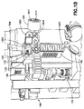
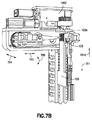
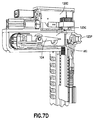
次に図1E〜1Hを参照すると、専用の処理システム100Aは、処理モジュールPM、自動化搬送および配置システム(ATPS)100、電子光線補助システムAUX、ATPS補助システムAUX2、振動制御プラットフォームVBC、および電子光線高電圧電源HVを含む。処理モジュールPMは、一態様においてはTEMとして構成されるが、別の態様において処理モジュールは、SEM、DB−FIB、STEMまたは他の任意の適切な電子光線顕微鏡/走査/撮像装置として構成される。例示のみを目的として、処理モジュールPMは、処理モジュールフレームPMFに接続されるカラムまたはハウジングPMCを含み、その一部が対物レンズチャンバ8CHを画定する。一態様において、自動化搬送および配置システム100の搬送および配置ユニット140は、例えば、電子顕微鏡システムの対物レンズチャンバ8CHと一体のケーシング140Fを有し、一体型のケーシングは、対物レンズチャンバ8CHと共通の雰囲気を有する搬送チャンバ125Cを形成する。カラムPMCは一般に、光学軸OAに沿って配置される任意の適切な電子源1(例えば、電圧源HVを有する)、引出電極2、第1の電極3および少なくとも第2の電極4などの、電子光学素子を含む。引出電極2は、電子源1の下流に位置付けられ、電子源1から電子を引き出すように構成される。第1の電極3は、電源位置に焦点を合わせるように構成され、少なくとも1つの第2の電極4は、電子源1からくる電子を加速するために設けられる(理解され得るように、少なくとも1つの第2の電極4は、電子光線EBの調整可能なエネルギーを可能にする)。
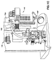
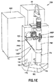
1E-1H, a
光学軸OAの残りの長さには、多段コンデンサCONDが設けられ、これは3つの磁気レンズ(例えば、第1の磁気レンズ5、第2の磁気レンズ6および第3の磁気レンズ7)を含み、これらに対して対物絞り10を備える磁気レンズの形態の対物レンズ8が配置される。上述のように、対物レンズ8および対物絞り10は、対物レンズチャンバ8CHを形成するカラムPMCの部分に配置される。理解され得るように、対物レンズチャンバ8CHは、本明細書においては専用の処理システム100Aに関して記載されているが、TEM、SEM、DB−FIBおよびSTEMなどの他の適切な電子顕微鏡システムも、対物レンズが位置付けられ試料が撮像のために配置される電子顕微鏡カラムの領域によって画定される対物レンズチャンバを含むことが理解されるべきである。調べられる試料サンプルが位置付けられる(本明細書に記載するように)対象面9は、対物レンズ8上に設けられるか、対物レンズ8に隣接して設けられる。補正装置16は、対物レンズ8の下流に設けられ、例えば対物レンズ8の球面収差を補正するように構成される。一態様において補正装置16は、対物レンズ8の後側焦点面を撮像し、対象面9の実中間像14を生成するように構成される第1のトランスファーレンズ11(一態様においては磁気レンズ)を含む。第1の補正システム12(一態様においては多極子)は、第1のトランスファーレンズ11により生成される中間像14の面に設けられる。第2の補正システム13(一態様においては多極子)および第2のトランスファーレンズ13は、第1の補正システム12の下流で接続される。第2のトランスファーレンズ15は、レンズを含むプロジェクタシステム18、19の入力画像面17で、対象面9の中間像14を撮像する。プロジェクタシステム18、19は対象面9に置かれ、プロジェクタシステム18、19の入力画像面17で撮像されるサンプルの画像を(例えば、撮像システムPISの)検出器20上に生成する。ここでも、上述の処理モジュールPMの構成が例示のみを目的としており、別の態様において処理モジュールは、TEM、SEM、DB−FIBまたは他の任意の適切な電子光線走査/撮像装置を形成する任意の適切な構成要素を含むことに留意する。
The remaining length of the optical axis OA is provided with a multistage capacitor COND, which includes three magnetic lenses (for example, a first
カラムPMCは、一態様においては、1つまたは複数のインターフェースポート180Pを含む。一態様において、1つまたは複数のインターフェースポート180Pは、撮像/分析のために任意の適切な方法でカラムPMC内に試料サンプルを挿入するための、モータ付きの絞りを含む。
The column PMC includes, in one aspect, one or
自動化搬送および配置システム100は、本明細書に記載されるように、処理モジュールフレームに連結されるか、処理モジュールフレームと一体形成されるフレーム140Fを含むので、ワークピース配置ユニット104は、例えば対象面9の対物レンズチャンバ8CH内、および電子光線EB(図1Gに図示)内にワークピース400を配置するために、カラムに対して位置付けられ、ワークピース400は、本明細書に記載されるように、トモグラフィー検査または他の任意の適切な撮像工程などのための試料の撮像中、ワークピース配置ユニット400のエンドエフェクタ101上に保持される。一態様において、ワークピース配置ユニットは、カラムPMCのポート180Pを通って延伸する。一態様において、自動化搬送および配置システム100は、例えば、本明細書に記載するような真空モジュール172、空気圧モジュール130および制御装置199を含む補助システムAUX2を含む。一態様において、処理モジュールPMおよび自動化搬送および配置システム100は、任意の適切な振動制御プラットフォームVBC上に取り付けられるか、あるいは支持される。一態様において、振動制御プラットフォームVBCは、システム100A内に生じるあらゆる振動を取り消すように構成される任意の適切なアクチュエータを含むアクティブな振動制御プラットフォームであるが、別の態様において振動制御プラットフォームVBCは、任意の適切な方法でシステム100A内の振動を取り消すように構成されるパッシブな振動制御プラットフォームである。
Since the automated transport and
システム100Aは、一態様においては、処理モジュールPM用の補助システムAUXおよび電源HVも含む。一態様において、補助システムAUXは、処理モジュール用の真空システム、冷却システムおよび制御システム(一態様においては制御部199と接続されるか、または一体化される)を含む。電源HVは、例えば高圧電源など、任意の適切な電源である。理解され得るように、本明細書に記載される専用の処理システム100Aの構成は例示的で例示のみを目的としており、別の態様において専用の処理システム100Aは、本明細書に記載されるようなサンプルを撮像および追跡するために、任意の適切な構成を有する。
The
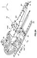
また図2A、2Bおよび2Gを参照すると、搬送モジュール125は、カセット102からワークピースを取り出し/設置し、ワークピースを処理モジュールPMに搬送し、処理モジュールPM内での処理の間ワークピースを支持するように構成される。ワークピース配置ユニット104は、少なくともX、Y軸に沿って、およびピッチ軸PX周りで、エンドエフェクタ101を移動させるように構成される複数の移動自由度を有する第1のシャトルステージ104S1(全体の配置ステージ)を含む。またワークピース配置ユニット104は、第1のステージによって運ばれるが分離しており、第1のステージとはその動作において異なる第2のシャトルステージ104S2(細かい配置ステージ)を含む。第2のシャトルステージ104S2は、少なくともY軸に沿って、および傾動軸TX(例えば、第1の傾動軸)周りでエンドエフェクタ101を移動させるように構成される、第1のシャトルステージ104S1からは独立した、複数の移動自由度を含む。第1および第2のシャトルステージ104S1、104S2の複合動作は、ワークピースを処理位置177に設置するために、処理モジュールPMの外側のワークピース保持ステーション(例えば、上述のような、カセット102の所定の取り出し/設置位置176)から、処理モジュールPM内の処理位置177まで延びる動作範囲をエンドエフェクタ101にもたらすので、エンドエフェクタ101は、処理モジュールPMの処理ステージを定める。
Referring also to FIGS. 2A, 2B, and 2G, the
第1のシャトルステージ104S1は、Y軸駆動部またはモータA3L、X軸駆動部またはモータA4Lおよびピッチ軸PX駆動部またはモータA5Lを含む。第1のシャトルステージ104S1は、フレーム140Fに取り付けられているものとして記載および図示されているが、別の態様において第1のシャトルステージ104S1は、処理モジュールPMの対応する機構と嵌合する、分離した異なる機械的ドッキングまたはロッキングインターフェースにより構成される。一態様において、駆動部A3L、A4L、A5Lのそれぞれ(ならびに本明細書に記載される他の駆動部)はそれぞれ、例えば、光学エンコーダ、レーザ干渉エンコーダ、容量または誘導エンコーダ、または他の任意の適切なエンコーダまたはそれらの組み合わせなど、任意の適切なエンコーダ248、246、247を含むことに留意する。一態様において、本明細書に記載されるエンコーダは、ピコメーターの位置分解能を有するが、別の態様においてエンコーダは、エンコーダが位置データを提供する軸のそれぞれの駆動モータの配置分解能に相応し得る任意の適切な位置分解能を有する。さらに別の態様において、本明細書に記載されるエンコーダは、それぞれの駆動モータの位置分解能よりも大きいか、または小さい配置分解能を有する。別の態様において本明細書に記載される駆動部は、駆動部の、任意の適切な一体型の位置検知能力を用いる。一態様においては、真空環境における駆動部の動作を可能にするために、駆動部A3L、A4LおよびA5Lの任意の適切な部分は、モータなどの部品を隔離するためにチャンバ125Cの雰囲気から密閉されることに留意する。別の態様において、駆動部A3L、A4LおよびA5Lは、任意の適切な方法で真空環境において動作するように構成されるが、さらに別の態様において、駆動部は、大気環境において動作するように構成される。Y軸(または長手方向の)駆動部A3Lは、Y軸に沿ってエンドエフェクタ101を移動させるために、任意の適切なモータと、任意の適切な機械的および/または固体状の電磁(および/または永久磁石)ガイド290を有する線形ステージとを含む。一態様において、モータは、配置分解能が1μm未満の超音波ピエゾモータであるが、別の態様において、モータは、ステッパモータ、ブラシレスモータ、ブラシモータなど、任意の適切な配置分解能を有する任意の適切なモータである。駆動部A3Lは、カセット102からワークピースを取り出すため、およびカセット102にワークピースを配置するため、ならびにY軸に沿ってワークピースを任意の適切な所望の距離だけ搬送するために、カセット102(例えば、カセットシャトル126のカセットグリッパ126Gにより保持される)に向かっておよびそこから離してエンドエフェクタを移動させるように構成される。また駆動部A3Lは、エンドエフェクタ101により保持されるワークピースの処理のために、処理モジュールPM内にエンドエフェクタ101を移動させるように構成される。
The first shuttle stage 104S1 includes a Y-axis drive unit or motor A3L, an X-axis drive unit or motor A4L, and a pitch axis PX drive unit or motor A5L. Although the first shuttle stage 104S1 is described and illustrated as being attached to the
X軸(または横方向の)駆動部A4Lは、X軸に沿ってエンドエフェクタ101を移動させるために、任意の適切なモータと、任意の適切な機械的および/または固体状の電磁(および/または永久磁石)ガイド290を有する線形ステージとを含む。一態様においてモータは、ピコメーター範囲の配置分解能を備えるステッピングピエゾモータであるが、別の態様においてモータは、ステッパモータ、ブラシレスモータ、ブラシモータなど、任意の適切な配置分解能を有する任意の適切なモータである。駆動部A4LおよびA5Lは積み重ねられている(例えば、一方の駆動部は他方の駆動部に取り付けられる)ものとして図示されているが、別の態様において第1のシャトルステージ104S1のXおよびY駆動部は、XおよびY軸の1つまたは複数に沿う動作が可能な磁性的に牽引されるプラテンなど、任意の適切な構成を有する複合された2次元駆動部である。駆動部A4Lは、チャンバ125CにおいてX軸に沿ってエンドエフェクタを横方向に移動させるように構成されるので、カセット102(例えば、カセットシャトル126のカセットグリッパ126Gにより保持される)内の全てのカラム、ならびにプリアライナステージ103は、ワークピースの取り出しおよび配置動作のためにエンドエフェクタ101によりアクセスされる。一態様において、駆動部A4Lは、ワークピースの処理中にワークピースのX方向への動作ももたらすために、処理モジュールPM内のエンドエフェクタ(およびその上に位置付けられるワークピース)をX方向に移動させるようにも構成される。
The X-axis (or lateral) drive A4L may be any suitable motor and any suitable mechanical and / or solid electromagnetic (and / or) to move the
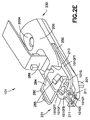
ピッチ軸PX駆動部A5Lは、ピッチ軸PX周りで第2のシャトルステージ104S2を枢動させるために、任意の適切なモータを含む。例えば、第2のシャトルステージ104S2は、第2のシャトルステージがピッチ軸PX周りで回転可能または枢動可能であるように、第1のシャトルステージ104S1に任意の適切な方法で枢動可能に取り付けられ得る。駆動部A5Lは、第1のシャトルステージ104S1および第2のシャトルステージの任意の適切な部分(例えば、第2のシャトルステージのハウジング104H)の両方に、任意の適切な方法で連結され、これにより駆動部A5Lは、ピッチ軸PX周りで第2のシャトルステージ104S2を枢動できる。一態様において、第1のシャトルステージ104S1に取り付けられるなど、任意の適切な場所に任意の適切なダンパーPXDが設けられ、これはハウジング104Hに対して、横方向の支持および緩衝を与えるように構成される。一態様において、ダンパーPXDは、柱268と、ハウジング104H(およびエンドエフェクタ101)の横方向の移動に係合し、抑制するように構成される任意の適切な弾性素子269とを含む。ピッチ軸周りでの第2のシャトルステージ104S2の枢動による移動は、エンドエフェクタ101の、矢印250の方向への移動を引き起こす。ピッチ軸PX周りでの、エンドエフェクタ101の矢印250の方向への移動は、Z軸に沿ってワークピースを移動させるのに役立ち、例えば所定の処理位置(例えば、TEM光線のユーセントリックな位置)でのワークピースの配置に用いられる移動を概算する。一態様において、駆動部A5Lは、カセット102および/またはプリアライナステージ103からのワークピースの取り出し、およびカセット102および/またはプリアライナステージ103へのワークピースの配置中の、小さな(例えば、±約3mm)Z軸動作のためにも利用される。一態様において、駆動部A5Lは、ピコメーターの配置分解能を備えるステッピングピエゾモータであるが、別の態様においてモータは、ステッパモータ、ブラシレスモータ、ブラシモータなど、任意の適切な配置分解能を有する任意の適切なモータである。別の態様において、ワークピース配置ユニット104は、Z軸に沿って第1または第2のシャトルステージ104S1、104S2の1つまたは2つ以上(またはワークピース配置ユニット104の他の任意の適切な部分)を移動させるように構成されるZ軸駆動部を設けられるので、ワークピース配置ユニット104は、例えば、9移動自由度を有する。
Pitch axis PX drive unit A5L includes any suitable motor to pivot second shuttle stage 104S2 about pitch axis PX. For example, the second shuttle stage 104S2 is pivotally attached to the first shuttle stage 104S1 in any suitable manner such that the second shuttle stage is rotatable or pivotable about the pitch axis PX. Can be. The drive A5L is coupled in any suitable manner to both the first shuttle stage 104S1 and any suitable portion of the second shuttle stage (eg, the second
第2のシャトルステージ104S2は、ハウジング104Hを有するアセンブリを含む。一態様においてハウジング104Hは、例えば駆動モータ(および他の任意の適切な構成要素)の動作環境をチャンバ125C内の環境(例えば、真空環境)から隔離するために、密閉されたハウジングである。図面に示されるハウジング104Hの形状は、単に例示的であり、別の態様においてハウジングは、任意の適切な形状を有する。ハウジング104Hは、エンドエフェクタの振動を抑制し、整定時間を減少させる質量および剛性をもたらすように構成される。一態様において、ハウジング104Hは、Y軸に沿ってエンドエフェクタを移動させるように構成されるY軸駆動部A6L(例えば、「速軸」)、および傾動軸TX周りでエンドエフェクタを回転させるように構成される傾動軸駆動部A7Rを収容する。別の態様において、Y軸駆動部A6Lは、Y軸に沿ったエンドエフェクタの移動が駆動部A3Lによりもたらされるように省かれてもよい。Y軸(または長手方向の)駆動部位A6Lは、Y軸に沿ってエンドエフェクタ101を移動させるために、任意の適切なモータと、任意の適切な機械的および/または固体状の電磁(および/または永久磁石)ガイドを有する線形ステージとを含む。一態様においてモータは、ピコメーターの配置分解能を備えるステッピングピエゾモータであるが、別の態様においてモータは、ステッパモータ、ブラシレスモータ、ブラシモータなど、任意の適切な配置分解能を有する任意の適切なモータである。駆動部A6Lは、駆動部A3Lが処理モジュールPM内にエンドエフェクタを配置(例えば、全体の配置)した後の、処理モジュール内のY軸に沿ったエンドエフェクタ(およびその上に保持されるワークピース)の精密性(例えば、細かな配置)および高速な移動をもたらすように構成される。処理モジュールPM内にワークピースを配置することにより、TEM撮像中などに、画像の「列」(例えば、Y軸に沿う異なる地点で取得されたワークピースの一連の画像)を取得するために、ワークピースを渡るときに、最大のスループットを提供する。この態様において、8〜24ミクロンの微小な移動は、駆動部A6Lによって100ms未満に完了され、「完了」とは、ワークピースの動作が約25〜約35msで約4nm未満に整定されることとして規定される。本明細書に開示される実施形態の態様は、2画像/秒よりも速い撮像速度を有する高スループットの走査をもたらす。
The second shuttle stage 104S2 includes an assembly having a
傾動軸駆動部A7Rは、エンドエフェクタ101に複数の移動自由度を与えるために、任意の適切な方法で駆動部A6Lに連結される。一態様において傾動軸駆動部A7Rは、線形軸受け265などの任意の適切な軸受けに取り付けられ、これはエンドエフェクタが駆動部A6Lにより配置されると、駆動部A7Rがエンドエフェクタ101と共にY軸に沿って移動させる。一態様において、接続部材260(後述)の軸方向の遊びを実質的に排除するために、任意の適切な予荷重されたスラスト軸受けアセンブリ267が設けられる。別の態様において、予荷重されたスラスト軸受けは省かれる。理解され得るように、A6L駆動部の位置フィードバックを提供するために、任意の適切な線形エンコーダ245が、A7R駆動部に取り付けられるか、A7R駆動部と一体形成される。別の態様において、線形エンコーダ245(および/または駆動部A7R用の回転エンコーダ)は、1つまたは複数のスケールがエンドエフェクタと駆動部A7Rとの間の任意の地点で接続部材上に置かれるように、接続部材260に組み込まれる。理解され得るように、エンコーダ245は、アブソリュートおよび/またはインクリメンタルエンコーダスケールを含む。一態様において、アブソリュートエンコーダは、軸受け310と駆動部A7Rとの間で接続部材260上に配置される一方で、インクリメンタルエンコーダは、軸受け310とエンドエフェクタとの間に配置される。さらに別の態様においては、アブソリュートエンコーダおよびインクリメンタルエンコーダの両方が、軸受け310とエンドエフェクタとの間、または軸受け310と駆動部A7Rとの間に配置される。さらに別の態様においては、アブソリュートエンコーダおよびインクリメンタルエンコーダ(またはその一部)の一方が駆動部A7Rのハウジング上にあり、他方が接続部材260上に配置される。一態様において線形エンコーダ245は、例えば、光学エンコーダ、レーザ干渉エンコーダ、容量または誘導エンコーダ、または他の任意の適切なエンコーダである(一態様において、駆動部A1L、A2L、A3L、A4L、A5L、A6L、A7R、A8Rはそれぞれ、エンコーダ245と実質的に同様のエンコーダを含むことに留意する)。別の態様において、Y軸駆動部A6Lは、傾動軸駆動部A7Rに取り付けられ、エンドエフェクタが駆動部A7Rにより駆動されると駆動部A6Lがエンドエフェクタ101と回転することを可能にするために、任意の適切な軸受けに取り付けられる。上述のように、傾動軸駆動部A7Rは、ワークピースの操作中、任意の適切な時点でエンドエフェクタ101およびその上に保持されるワークピースを傾動軸TX周りに回転させるように構成される。例えば、駆動部A7Rは、例えばTEM光線のユーセントリックな地点を位置付けるため、およびワークピースの画像が異なる角度のそれぞれで取得されるようにワークピースが異なる角度に傾斜されるトモグラフィー用途のために、ワークピースが処理モジュールPM内にある間、エンドエフェクタ101およびその上に保持されるワークピースを回転させる。一態様において、A7R駆動部は、傾動軸TXに沿った位置フィードバックを提供するために、任意の適切なエンコーダ(上述のものなど)も含むことに留意する。駆動部A6Lは、ピエゾモータ、ステッパモータ、ブラシレスモータ、ブラシモータなどの、任意の適切なモータを含む。
The tilting shaft driving unit A7R is coupled to the driving unit A6L by any appropriate method in order to give the end effector 101 a plurality of degrees of freedom of movement. In one aspect, the tilt axis drive A7R is attached to any suitable bearing, such as a
エンドエフェクタ101は、図3A〜3Dに関して後述されるように、1つまたは複数の適切な軸受け(軸受け390を参照)および/または1つまたは複数のダンパー(ダンパー320、321を参照)などを用いて、任意の適切な方法でハウジング104H内に支持される接続部材または従動部材260によるなど、任意の適切な方法で駆動部A6L、A7Rの1つまたは複数に連結される。一態様において、接続部材は、所定の長さY1および質量を増大させて(例えば、接続部材と駆動部A6Lとの間の駆動部A7Rの配置を介して)構成され、ハウジング104Hは、接続部材260が本明細書に記載される時間内に整定するためのエンドエフェクタ101の移動を可能にしつつ1つまたは複数の軸受け390により支持される(例えば、実質的にダンパーなしに)ように、所定の剛性をもたらすように構成される。別の態様においては、エンドエフェクタ101単独の移動、または接続部材260の構成、ハウジング104Hおよび/または軸受け390の構成とエンドエフェクタ101との複合移動を整定するために、1つまたは複数のダンパー(図示せず)がハウジング104H内に配置される。
The
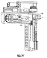
次に図2C〜2Fを参照すると、エンドエフェクタ101は、任意の適切な構成を有する本体200を含む。一態様において本体200は、取り付け部分230と取り付け部分230から延伸するワークピースインターフェース部分231とを有する一体(例えば、一片単位)の部材である。取り付け部分230は、本体の凹部200R内への接続部材260の挿入および任意の適切な化学的または機械的締結具(これは開口200Aを通過し得る)を用いた接続部材260への本体の固定などにより、任意の適切な方法で接続部材260に取り付けられるか、あるいは接続部材260と連動するように構成される。別の態様において、エンドエフェクタ101および接続部材260は、エンドエフェクタが任意の適切な運動学的位置合わせ機構との「スナップ形式の」インターフェースを有するように構成されるので、エンドエフェクタ101は、実質的にツールを用いずに接続部材260に導入され、および/または、接続部材260から取り外され(例えば、ツールなしでの導入)、これはエンドエフェクタの迅速な交換をもたらす。ワークピースインターフェース部分231は、ワークピース検出部材280とワークピースインターフェース部材232とを含む。本体200は、スロット250の一方の側面において略平らな表面250FSを有し、スロットの他方の側面において分岐表面を有するスロット250を含み、分岐表面は、以下にさらに記載される軸受け210を形成する。エンドエフェクタ101は、グリッパ屈曲部101GFとグリッパワークピース支持表面101GSとを有するグリッパ101Gを含む。一態様において、グリッパワークピース支持表面101GSは、ワークピースインターフェース部材232と一体形成される。一態様において、グリッパワークピース支持表面101GSは、グリッパワークピース支持表面101GSに隣接して配置される1つまたは複数の一体型のワークピースバンパー211を含む。バンパー211は、例えば、ワークピースの側端と連動し、ワークピース支持表面101GSとグリッパ屈曲部101GFのグリッパトング101GTに対してワークピースを配置する(例えば、ワークピースの側端とバンパー211との間の実質的な接触を通して)ために任意の適切な形状を有する。一態様においてワークピースインターフェース部材232は、ワークピースがグリッパ101Gにより把持されていないときにグリッパトング101GTが係止するワークピース支持表面101GSの片側に凹部も含むので、屈曲部の弛緩状態は、グリッパ101Gにより保持されるワークピースのポジティブなグリッパ係合をもたらすために、ワークピース支持表面101GSの下に配置される。一態様において、グリッパ屈曲部101GFは、基部101GFB、基部101GFBの一方の面から離れるように延伸する1つまたは複数の屈曲部のツメ101GFT、および屈曲部のツメ101GFTの延伸方向と略反対側の方向で基部101GFBの別の面から延伸する1つまたは複数のグリッパトング101GTを含む。屈曲部のツメ101GFTは、グリッパ屈曲部101GFを本体200に固定するため、およびグリッパ屈曲部をスロット250の略平らな表面に向かって付勢するために、スロット250内に延伸するように構成される。1つまたは複数のグリッパトング101GTは、ワークピース支持表面101GSと並んで延伸するように構成される。ワークピースインターフェース部材232は、レバー部材またはスパー(spar)201が通って延伸する開口235を含む。レバー部材201は、レバー部材201が開口201を通って本体200の外周面を越えて延伸するように、グリッパ屈曲部101GFの基部101GFBに連結される。グリッパ屈曲部101GFは、グリッパを開閉するために、スロットの略平らな表面250FSと軸受け210との間で可動であることに留意する。
2C-2F, the
駆動部A6Lおよび駆動部A3Lは、以下に記載するようにエンドエフェクタ101のグリッパ101Gを作動させるために、Y軸に沿った反対方向への同時動作のために構成される。駆動部A6LおよびA3Lの反対方向への移動は、エンドエフェクタ101と第2のシャトルステージ104S2との間の相対的な移動を引き起こす(例えば、エンドエフェクタ101を所定の位置に維持したまま)ので、エンドエフェクタ101のレバー部材またはスパー201は、ハウジング104Hの一部に接触する。レバー部材201とハウジング104Hとの間の接触は、レバー部材201の移動をもたらすので、レバー部材201は、グリッパ撓み部101GFが矢印220の方向でグリッパワークピース支持表面101GSから離してグリッパトング101GTを移動させるために撓み、ワークピースの取り出しまたは設置のためにグリッパを開放するように、レバー部材201が連結されるグリッパ撓み部101GFを、エンドエフェクタ101の支持部210に係合させる。グリッパは、グリッパを閉鎖するかあるいはワークピースを把持するために、レバー部材201がハウジング104Hから離れるように移動させられ、グリッパ撓み部101GFの付勢力がグリッパワークピース支持表面101GSに向かう矢印220の方向におけるグリッパトング101GTの移動を引き起こすように、実質的に反対の方法で閉鎖される。
The drive unit A6L and the drive unit A3L are configured for simultaneous operation in opposite directions along the Y axis to actuate the
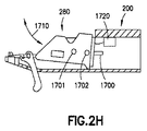
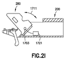
ワークピース検出部材280は、ワークピースの操作前、操作後、および/または操作中に、ワークピースを検出あるいは撮像するために、ワークピースグリッパ101Gに隣接して本体200に機械的に取り付けられる。ワークピース検出部材280と本体200との間の機械的な取り付けは、静的な取り付け(例えば、ワークピース検出部材280は本体200に対して固定される)またはワークピース検出部材280の、例えば本体200またはハウジング104Hの任意の他の適切な部分内への後退をもたらす、動的な取り付け(例えば、ワークピース検出部材280と本体との間の、相対移動、自動化またはモータによる移動、または手動動作が可能である)である。一態様において、ワークピース検出部材280は、エンドエフェクタが処理モジュールPM内に入る前に後退されるが、別の態様においてワークピース検出部材280は、任意の適切な時点で後退される。また図2Hおよび2Iを参照すると、一態様においてワークピース検出部材280(後退位置に示す)は、レール1700と係合するガイド部材1701、1702を含むので、ワークピース検出部材280は、展開位置と後退位置との間で矢印1710の方向に可動である。別の態様において、ワークピース検出部材280(展開位置に示す)は、枢動軸1703を含むので、ワークピース検出部材280は、展開位置と後退位置との間で矢印1711の方向に枢動する。理解され得るように、ワークピース配置ユニット104は、後退位置と展開位置との間で、任意の適切な方法で矢印1710、1711の方向にワークピース検出部材280を移動させるために、任意の適切なアクチュエータ1720、1721を含む。
The
一態様において、ワークピース検出部材280は、任意の適切なセンサ281、任意の適切なレンズ282、任意の適切なレンズ取付け具283、および、センサ281がグリッパ101G上あるいはグリッパ101Gの近くで保持されるワークピースを検出あるいは撮像できるように、任意の適切な角度を有するミラー284(ミラー面284Mを備える透明なプリズム)を含む。一態様において、ミラー284は、より小型な構成を得るためにワークピース検出部材280の光路を折り返すように構成されるが、別の態様においてワークピース検出部材280は鏡を含まなくてもよい。一態様において、ワークピース検出部材280は、センサ281によるワークピースの検出を可能にするために、任意の適切な単一または複数の波長の光を提供するための、1つまたは複数の適切な照射部材285も含む。フレキシブル回路286は、センサ281を任意の適切な制御装置(制御装置199や、制御装置199に接続され、ハウジング104H上など、任意の適切な場所に配置されるワークピース検出部材制御装置280Cなどの任意の中間制御装置など)に連結するので、センサ281は制御装置に信号(例えば、エッジ検出、バーコード読み取り、基準検出、連続した画像が平行の軸により2つの異なる位置から取得される疑似ステレオ位置など)を送り、制御装置は信号に関して任意の適切な画像分析を行うように構成される。
In one aspect, the
別の態様において、ワークピース検出部材280は、グリッパ101Gおよびグリッパに保持されるかグリッパに隣接する任意のワークピースが見られる視野を提供しつつ、上述のような静的な取り付けまたは動的な取り付けで、ハウジング104H(またはチャンバ125C内および/またはワークピース配置ユニット104上の他の任意の適切な場所)に取り付けられる。ワークピース検出部材280をハウジングに取り付けると、エンドエフェクタからフレキシブル回路286を取り除き、これはエンドエフェクタの移動整定時間を減少させることに留意する。ワークピース検出部材280(ハウジングまたはエンドエフェクタに取り付けられる)は、ワークピース配置ユニット104と共に一体アセンブリとして移動することに留意する。
In another aspect, the
一態様においてセンサ281は、カメラまたは他の光学検出器であるが、別の態様においては、電磁スペクトルの広い範囲にわたって高性能の並行データストリームを提供するために、単一の装置、2Dおよび3Dアレイ(ラインスキャン、CCDなど)などの複数の検出器が組み込まれる。図面においては1つのセンサ281のみ(例えば、単眼視)が示されているが、別の態様において、エンドエフェクタ101は、1つまたは複数のセンサ281を有するか、および/または、1つまたは複数のセンサが上述の方法と同様にエンドエフェクタから離れて取り付けられる。例えば、エンドエフェクタは、(例えば、ワークピースに対するグリッパの、または、ワークピース保持ステーションまたは処理位置に対するグリッパにより保持されるワークピースの)真のステレオ位置を可能にする双眼視またはステレオ視能を、共通の焦点であるが異なる光学軸を用いて提供する、2つのセンサを有する。双眼視は自動の特徴認識(ワークピースの空間的位置、バーコード、基準など)およびエンドエフェクタ/ワークピースの配置に有益であり、分離した画像が三次元機能(例えば、眼鏡やヘッドセットを用いる)によりスクリーン上でユーザによって見られ得る、バーチャルリアリティモードを可能にする。複数のセンサ281は、ステレオ顕微鏡画像と同様の画像を生成するために用いられる。一態様において、レンズ282およびレンズ取り付け具283は、モータ付きのフォーカスおよびズーム制御を含む。理解され得るように、ワークピース検出部材280は、ワークピースの有無の検出、ワークピースの識別、ワークピース保持位置でのワークピースに対するグリッパ101Gの位置合わせ、グリッパに保持されるワークピースの、ワークピース保持位置または処理位置に対する配置、プリアラインメントステージ103を用いるワークピースの位置合わせのためのワークピースの撮像、または、ワークピース、グリッパおよび/または任意の適切なワークピース保持位置についての、他の任意の適切な識別および/または位置に関する情報の1つまたは複数を提供するように構成される(制御装置199での適切な画像処理と共に)。
In one aspect, the
理解され得るように、一態様において、視覚システムは、ワークピース400の取り出しおよび配置場所または自動化搬送および配置システム100内の他の任意の適切な場所を見るために、エンドエフェクタおよび/またはハウジングから離れて取り付けられる1つまたは複数のセンサCAM1〜CAM5を含む。一態様において、離れたエンドエフェクタセンサCAM1〜CAM5は、エンドエフェクタ101がセンサ281を含まないか、エンドエフェクタ101上のセンサ281が用いられない場合に用いられるが、別の態様において離れたエンドエフェクタセンサCAM1〜CAM5は、エンドエフェクタのセンサ281と連動して用いられる。上述のように、一態様において、視覚システム(エンドエフェクタから離れて取り付けられるか、および/または、エンドエフェクタ上に取り付けられる1つまたは複数のセンサを含む)から得られた情報は、データベースDS(一態様においては検査室情報管理システムLIMSの一部)を通したワークピースおよびその上の試料の追跡を可能にする。例えば、一態様において、1つまたは複数のセンサCAM1は、例えばカセットシャトル126による、マガジン105への、およびマガジン105からのカセット102の移送を撮像するために、任意の適切な方法でフレーム140Fに取り付けられる。別の態様において、1つまたは複数のセンサCAM2は、所定の取り出し/配置位置またはワークピース保持ステーション176に位置付けられるカセット102への、およびカセット102からの、エンドエフェクタ101(上述のワークピース検出部材280に加えて、または代えて)によるワークピース400の移送を撮像するためにフレームに取り付けられる。さらに別の態様において、1つまたは複数のセンサCAM3は、プリアライナステージ103への、およびプリアライナステージ103からの、ワークピースの取り出しおよび配置を見るために、任意の適切な場所でフレーム140Fに取り付けられる。一態様において1つまたは複数のセンサCAM3は、プリアライナステージ103とZ方向に移動するために、プリアライナステージ103および/またはカセットシャトルに取り付けられるが、別の態様において1つまたは複数のセンサCAM3は、フレーム140Fに対して静止している。一態様において、1つまたは複数のセンサCAM4は、ロードロック120内に配置されるマガジン105および/またはカセット102を撮像するために、ロードロック120内に取り付けられる。一態様において、1つまたは複数のセンサCAM5は、ワークピース400を、例えば処理モジュールの電子光線と位置合わせするために、処理モジュールPM内に取り付けられる。理解され得るように、一態様において、カメラCAM2などの共通のカメラは、例えば、カセット102およびプリアライナステージ103など、複数の場所からのワークピースの取り出しおよび配置を見るように配置および構成される。別の態様においては、共通のカメラが、カセットシャトル126によるカセットの把持、ワークピース保持ステーション176での、カセット120への、およびカセット120からのワークピース400の移送、および、プリアライナステージ103への、およびプリアライナステージ103からのワークピース400の移送を見るように配置および構成される。1つまたは複数のセンサCAM1、CAM2、CAM3、CAM4は、上述のセンサ281と実質的に同様であり、一態様において、1つまたは複数のセンサCAM1、CAM2、CAM3、CAM4は、単眼視カメラであるが、別の態様において1つまたは複数のセンサCAM1、CAM2、CAM3、CAM4は、ステレオカメラである。本明細書に記載のステレオカメラは、各レンズのフィルムフレームに対して分離した画像センサを備える2つ以上のレンズを含むので、三次元の画像(例えば、ステレオ撮影)を捉えるためにカメラにヒトの両眼視力を刺激させることに留意する。一態様において、制御装置199は、ステレオカメラからの1つまたは複数の三次元画像に基づき、本明細書に記載のグリッパ(エンドエフェクタ101およびカセットシャトル126のグリッパなど)と、それぞれの保持領域(例えば、マガジン105、カセット102、プリアライナ103または他の任意の適切なワークピースまたはカセット保持領域)へ、およびそれぞれの保持領域から、ワークピース400および/またはカセット102を取り出し、また配置するときに把持されるワークピース400またはカセット102との間の範囲または距離を決定するように構成される。別の態様において、本明細書に記載のグリッパとそれにより把持されるワークピース400またはカセット102との間の範囲または距離は、任意の適切な方法で決定される。
As can be appreciated, in one aspect, the vision system can be removed from the end effector and / or housing to view the removal and placement location of the
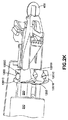
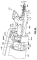
図2J〜2Lを参照すると、ワークピース配置ユニット104およびエンドエフェクタ101は、エンドエフェクタが軸TX(図2A)周りで回転し、エンドエフェクタ101の少なくとも一部が軸TX2(図2J、例えば、第2の傾動軸)周りで回転するように構成される。この態様においてエンドエフェクタ101は、注記する以外は上述のものと実質的に同様である。例えば、本体200は、ベース部分200Mと傾動部分200Tとに分けられ、ベース部分200Mは、接続部材260が傾動軸駆動部A7Rにより回転されるとエンドエフェクタ101が接続部材と一緒に回転するように、接続部材260と係合するように構成される。傾動部分200Tは、軸受け1200などの任意の適切な軸受けによりベース部分200Mに可動に取り付けられるので、傾動部分200Tは、ワークピース400がエンドエフェクタにより保持されるときのワークピース400の回転中心CRと一致する、軸TX2周りで回転する。一態様において軸受け1200は、ベース部分200Mとモノリス単位で一体形成されるが、別の態様において軸受け1200およびベース部分200Mは、任意の適切な方法で結合される。軸受け1200は、内輪1201Cと少なくとも1つの外輪1201A、1201Bとを含み、内輪1201Cと外輪1201A、1201Bのそれぞれとの間には、任意の適切な玉軸受け1202(ケージ1202C内に保持される)が配置される。玉軸受け1202は、セラミックなど任意の適切な材料で構成される。理解され得るように、軸受け1200の内輪1201Cおよび外輪1201A、1201Bは、ゴニオメーターの移動をもたらす適切な弧状の構成を有し、傾動部分200Tは、軸TX2周りで、例えば、軸TXに対して±10°など、任意の適切な距離だけ矢印1210の方向に移動する。別の態様において傾動部分は、±10°よりも多い量または少ない量だけ、矢印1210の方向に可動である。
Referring to FIGS. 2J-2L, the
図2Kおよび2Lに見られるように、外輪1201A、1201Bの少なくとも1つは、ベース部分200Mおよび接続部材260の1つまたは複数の中に少なくとも部分的に配置される少なくとも1つのギヤ1204を係合するように構成されるギヤラック1203を含む。一態様においては、単一の外輪1201A、1201Bのギヤラック1203に係合するために単一のギヤ1204が設けられる。一態様においてギヤ1204は、傾動軸駆動部A15Rを係合するために少なくとも部分的に接続部材260を通って延伸する駆動シャフト1205に取り付けられるか、あるいは連結される、ピニオンギヤなどの任意の適切なギヤである。傾動軸駆動部A15Rは、駆動シャフト1205を駆動させるためにハウジング104H内の任意の適切な場所に配置される。一態様において、傾動軸駆動部A15Rおよび駆動シャフト1205の構成は、傾動軸駆動部A7Rおよび接続部材260の構成と実質的に同様であり、傾動軸駆動部A15Rは軸TX周りで駆動シャフト1205を回転させる。理解され得るように、駆動シャフト1205はエンドエフェクタの整定時間を減少させるために、任意の適切なダンパー(接続部材260に関して記載したものと実質的に同様)を含む。理解され得るように、ギヤ1204は、駆動シャフト1205と一緒に回転するように駆動シャフト1205に連結される。ベース部分200Mは、ギヤ1205が回転されるとエンドエフェクタ101(およびそれにより保持されるワークピース400)の傾動部分200Tが軸TX2周り(例えば、ワークピース400の回転中CR)で矢印1210の方向に回転するように、ギヤ1205およびギヤラック1203が互いに係合するときに通る開口200MAPを含む。
As seen in FIGS. 2K and 2L, at least one of the
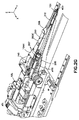
次に図1Bおよび3A〜3Eを参照すると、開示される実施形態の態様によるワークピース配置ユニット304が提供され、ワークピース配置ユニット304は、例えば、TEM内にワークピースを配置するための実質的に全ての必要な自由度を提供するTEM(または、他の態様においては、SEM、DB−FIB、STEMまたは他の適切な電子光線顕微鏡装置)の、例えば、駆動/配置ステージまたは他の任意の適切なユニット181と連動するように構成される。TEMの配置ステージ181の適切な例は、FEI製のCompuStage(商標)である。この態様においてワークピース配置ユニット304は、配置ステージ181によりもたらされる移動速度および整定時間と比較して、長手軸に沿う(例えば、ここで示す例においてはY軸に沿う)ワークピース配置ユニットの移動速度を増加させ、整定時間を減少させるために、Y軸に沿ってエンドエフェクタを移動させるように構成される軸駆動部A6L(例えば、「速軸」)を含む。上述のように、駆動部A6Lを用いて処理モジュールPM内にワークピースを配置することにより、TEM撮像中などに、画像の「列」(例えば、Y軸に沿う異なる地点で取得されたワークピースの一連の画像)を取得するために、ワークピースを渡るときに、最大のスループットを提供する。
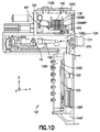
Referring now to FIGS. 1B and 3A-3E, a
一態様において、配置ユニット304は、ハウジングまたはフレーム300、ハウジング300から延びる管状部材310、管状部材を通って延びる接続部材360、線形駆動部A6L(上述)および駆動部エンコーダ330を含む。管状部材310は円筒状の管として図示されているが、別の態様において管状部材は、TEMまたは他の適切な処理モジュールPMの嵌合開口内に挿入されるように構成される任意の適切な形状を有する。一態様において、管状部材310は、一片構成を有するが、別の態様において管状部材310は、締り嵌め、機械的締結具または化学的締結具などを通して、任意の適切な方法で互いに対して連結されるベース部材310Bと延伸部材310Bとを含む(図3D参照)。ハウジング300は、駆動部A6Lおよびエンコーダ330(読み取りヘッド330Hと、例えば、エンコーダ245と実質的に同様に1つがアブソリュートで1つがインクリメンタルなど、1つまたは複数のテープスケール330TSを有するテープスケールユニット330Sとを含む)が取り付けられるチャンバ300Cを形成する。ハウジングおよび/または管状部材は、TEMの光線に対してエンドエフェクタを位置付けるために、配置ステージ181と連動する1つまたは複数の機構を含む。例えば、配置ステージ181は、管状部材310が挿入されるときに通る開口181Pを含む。また配置ステージ181は凹部181Tを含み、ハウジングは凹部181Tに係合するように構成される位置付け部材300Tを含む。一態様において、管状部材360は、開口181P内の対応する軸受け面と係合するように構成される先端軸受け面360TBも含む。管状部材はまた、開口181P内の対応するショルダと係合するショルダ360TSを、管状部材360に沿う任意の適切な位置で含む。管状部材360、先端軸受け面360TB、ショルダ360TSおよび配置部材300Tの1つまたは複数は、TEMの光線のX、Y、Z軸およびピッチ軸にエンドエフェクタを配向するために、配置ステージ181に対してエンドエフェクタを配置する。
In one aspect, the
この態様において駆動部A6Lは、テープスケールユニット330Sを通して接続部材360に連結される。例えば、テープスケールユニット330Sは、任意の適切な線形ガイド部材330Gを通してハウジング300に取り付けられるので、1つまたは複数のテープスケール330TSは、Y軸に沿って線形に可動である。テープスケールユニット330Sは、テープスケールユニット330Sの両側にY軸に沿って配置される連結部301A、301Bを含み、駆動部A6Lは一方の連結部301Bに連結され、接続部材360は他方の連結部301Aに連結される。接続部材360は、連結部301Aから管状部材310を通って延びるので、エンドエフェクタ301は、ハウジング300に対して管状部材310の遠位端DEに隣接して配置されるか、遠位端DEを通り過ぎて延びる(管状部材は、ハウジングに対して管状部材の近位端でハウジングに連結される)。接続部材360は、例えば、任意の適切な軸受けおよび/またはダンパーを用いるなど、任意の適切な方法で管状部材310内に支持される。一態様において管状部材310は、それぞれのダンパー320、321を導入あるいは使用可能にするために、1つまたは複数のダンパーアクセスポート370A〜370D、371A〜371Dを含む。ダンパーアクセスポートは、例えば、管状部材310の内部を外部環境から隔離するために、それぞれのダンパーアクセスポート370A〜370D、371A〜371Dを密閉するように構成される被覆部372、373を含む。一態様においてダンパー320、321は、任意の適切なエラストマー(または他の任意の適切な材料)で構成され、接続部材360が部材310内で線形に移動すること、および/または、接続部材が管状部材310内でスピンまたは傾動する(例えば、図2Aに示す傾動軸TX周りで)ことを可能にするよう構成される。例えば、ダンパー372、373は、ボール形状か、または他の任意の適切な形状および/または構成を有する。ダンパー372、373は、整定時間を減少させるために接続部材360および/またはエンドエフェクタ301の振動を抑制するよう、管状部材310の長さに沿う任意の適切な位置に配置される。例えば、ダンパーは、エンドエフェクタ/接続部材の移動中に駆動部A6Lにより誘発される接続部材360の振動を減少するか実質的に取り除く。一態様においてダンパーは、エンドエフェクタの8〜24ミクロンの移動に対して提供され、実質的に全ての振動が50ms未満に約4nm〜約5nm未満まで抑制または整定され、別の態様においては、約25ms〜約35ms未満に約4nm〜約5nm未満まで整定される。別の態様においてダンパーは、任意の適切な長さの移動および任意の適切な整定時間のために提供される。接続部材360も、軸受け390によって管状部材310の遠位端DEに隣接して管状部材310内に支持される。軸受け390は、接続部材およびエンドエフェクタを移動させるときの軸方向の摩擦を最小限にしつつ、管状部材310内の接続部材360に堅固な横方向の支持をもたらすように構成される。軸受け390は、接続部材360を周方向に取り囲む軸受けスリーブ390Sを含む。スリーブは、玉軸受けなどの任意の適切な転がり素子390REを、互いから所定の距離Y2をあけて配置する1つまたは複数のセパレータまたはケージ390Rを形成する。距離Y2は、接続部材360に剛性を与え、および/または、整定時間を減少させるために接続部材360および/またはエンドエフェクタ301の振動を抑制する、任意の適切な距離である。セパレータ390Rは、図3Bに見られるように、接続部材360の周方向周りに転がり素子390REを周方向に配置するように構成される。また、軸受け390の内輪および外輪は、転がり素子390REが接続部材360および管状部材310の内壁に実質的に直接接触するように、接続部材360(例えば、内輪)および部材310の内側表面(例えば、外輪)により形成されることに留意する。一態様において、転がり素子390REと接続部材360/管状部材310との間には、小さな締り嵌め(例えば、一態様においては約2ミクロン、別の態様においては2ミクロンよりも大きいか、または小さい)が存在する。転がり素子390REは、例えば、セラミック、金属、複合材料などの任意の適切な材料から構成される。
In this aspect, the drive unit A6L is coupled to the
一態様においては、駆動部A6Lおよびハウジング300のチャンバ300Cを、エンドエフェクタが位置付けられる環境から密閉あるいは隔離するために(例えば、配置ユニットのワーク保持領域を処理モジュール外部の大気圧から隔離するために)、管状部材310内に任意の適切なシールが位置付けられる。例えば、チャンバ300Cを密閉あるいは隔離するために、管状部材310内の任意の適切な場所に任意の適切なベローズシール376が設けられるので、ポンプされる量(例えば、真空または別の所定の環境に露出される管状部材内のカラム)は最小限にされる。一態様においてベローズシール376は、ダンパー372、373の間に長手方向に(例えば、接続部材の長手軸に沿って)位置付けられる。別の態様において、管状部材310は、上述のように一緒に連結される個別の片から形成され、ベローズシール376は、片の結合体または連結部に位置付けられるか隣接して位置付けられる(例えば、ベローズシール376の容易な装着を可能にするために、ベース部材310Bが延伸部材310Eに連結される場所に隣接する)。
In one aspect, the drive A6L and the chamber 300C of the
エンドエフェクタ301は、例えば、エンドエフェクタ101に関して上述したものと実質的に同様の方法で、接続部材360に連結される。この態様においてエンドエフェクタ301は、手動で作動されるエンドエフェクタであるが、別の態様においてエンドエフェクタは、上述のものと実質的に同様である。この態様において、エンドエフェクタは、接続部材360を係合するように構成される本体301B(例えば、上述の方法と実質的に同様の方法で)と、本体から延びるワークピース保持位置301Hと、クランプ部材301Cとを含む。クランプ部材301Cは、ばねクランプ(例えば、閉鎖位置に付勢される)または手動で開閉される他の任意の適切なクランプである。別の態様においてクランプ部材は、ワークピース400を把持するために任意の適切な方法で開閉される。別の態様において、上述のワークピース検出部材280は、上述の方法と実質的に同様の方法で、エンドエフェクタ301に取り付けられる。
The
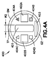
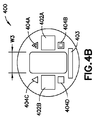
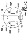
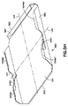
次に図4A〜4Eおよび図4G〜4Jを参照すると、ワークピース400、400A、400A1、400A2、400A3、400A4が示される。ワークピース400、400A、400A1、400A2、400A3、400A4は、任意の適切なワークピースであり、例示のみを目的として、TEMグリッドの試料ホルダとして示される。一態様において、ワークピース400、400Aは、円盤構成を有するが、別の態様においてワークピースは、半月形状(リフトアウトワークピース/グリッドの形態を有するワークピース400A1、400A2、400A3、400A4を参照)などの他の任意の適切な形状を有する。一態様において、ワークピース400、400A1、400A2、400A3、400A4は、単一の一体構成を有する(例えば、モノリス部材として形成される)が、別の態様においてワークピース400Aは、以下により詳細に記載されるように、ベース部材BMAに取り付けられるか、あるいは連結される交換可能または選択可能の薄膜またはウェブ450A〜450Hを有する。一態様において、本明細書に記載されるワークピース400、400A、400A1〜400A4は、ケミカルミーリング、レーザ微細加工、スタンピングの1つまたは複数、または他の任意の適切な方法により形成される。一態様において、ワークピース400は、第1の表面400Tと反対の第2の表面400Bとを備える薄いシート状のベース部材BMを含み、第1の表面は、ワークピース400により保持される試料保持フィルム用の座面および支持面を画定する。一態様において、ベース部材BMは、ベリリウム銅合金から構成されるが、別の態様においてベース部材は、任意の適切な材料から構成される。さらに別の態様において、ベース部材BMは、サブミリメータ幅のシートであるが、別の態様においてベース部材BMは、任意の適切な厚さを有する。
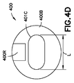
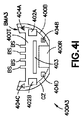
4A-4E and 4G-4J,
ベース部材BMは、サンプル/試料ホルダにより保持される保持フィルムを露出する第2の表面400Bを通る開口またはスロット401(以下にさらに詳細に記載)を含み、また、少なくとも第1の表面400Tの部分上に画定され、エンドエフェクタ101、301のグリッパの係合を受容するように配置されるグリップ係合域GZを含む。一態様において、グリッパ用の、ベース部材BMのグリップ係合域GZは、ベース部材BMの周縁に隣接するか周縁にある、360度の径方向領域である。一態様において、グリップ係合域GZは、ワークピース400の、中央の薄くされた部分TP(グリップ域により囲まれている)よりも広く、ワークピースはモノリスの一体部材である。本明細書に記載されるものと実質的に同様の方法で、ワークピースの中央の薄くされた部分TPは、試料サンプルを支持するために中に形成される、任意の適切なサイズ、形状などを有する任意の適切な数の開口を含む。別の態様において、ベース部材BMは、ワークピース400が手動、自動または他の任意の方法で把持されるような把持表面を提供するために、例えば、第2の表面400B(例えば、表面400Tの反対)上に凹部400Rを含む。以下にさらに詳細に記載されるように、第1または第2の表面400T、400Bの少なくとも一方は、それぞれのワークピース上に保持される試料またはサンプルの物理的な表示であるデータを表すパターンで配置される、上に形成される機械が読み取り可能な構造を含み、試料またはサンプルの物理的な表示は、一態様においては、以下にさらに詳細に記載するようにサンプルホルダの少なくとも1つの所定の特徴を定める。また後述されるように、所定の特徴は、エラー補正特徴を備える、サンプルおよび/またはサンプルホルダの固有の識別マークであってもよい。
The base member BM includes an opening or slot 401 (described in more detail below) through the
上述のように、ワークピース400は、試料が保持されるスロット401を含む。一態様においてスロット401は、任意の適切な所定の長さLと、任意の適切な幅W1、W2、W3とを有する(3つの幅が図示されているが、別の態様においてワークピース400は、任意の適切な幅および/または長さを有するスロット、または任意の適切な幾何学的形状を有する開口を設けられ得る)。この態様においてスロットは、1つまたは複数の試料を保持するために、任意の適切な網の目形状または他の適切な形状を含む。さらに別の態様において、ワークピースはスロットを含んでいなくてもよい。一態様においてスロット401Cの角は、例えば、長方形の試料サンプルに対してより撮像可能な面積を与えるために、丸みを帯びている。
As described above, the
一態様において、上述のように、ワークピース400は、構造体が置かれる少なくとも1つの第1または第2の表面400T、400Bの基準面に対する三次元のトポグラフィを定める1つまたは複数の構造体または識別マーク(例えば、読み取り可能なデータ記憶媒体)を含み、構造体は、構造体が置かれる少なくとも1つの第1または第2の表面400T、400Bと一体形成される。一態様において、構造体は、少なくとも1つの第1または第2の表面400T、400B上に対称に配置され、重複した読み取り場所を提供する一方で、別の態様において、構造体は、互いに対して、および/または、第1または第2の表面400T、400Bに対して、任意の適切な配置を有する。一態様において、構造体は、任意の適切な場所に、任意の適切な方法でワークピース400の第1の表面400T(例えば、試料はこの表面から見られる)上に形成され得る、二次元のデータ行列バーコード402A、402Bなどの識別子である。一態様において、バーコード402A、402Bは、スロット401の反対側の表面上に刻まれるか、または微細加工される。一態様において、各バーコードは、バーコードの全長に沿って(例えば、1−Dバーコード用)またはバーコードの少なくとも片側に沿って(例えば、2−Dバーコード用)少なくとも14のセルを含む一次元または二次元のバーコードであり得る。別の態様においては、バーコードの全長に沿って14よりも少ないか、または多いセルが設けられる。例えば、一態様においてバーコードは、例えば検査室情報管理システムLIMSまたは他の任意の適切なデータベースまたは追跡システムにおいて、本明細書に記載するように試料を固有に識別するために、エラー補正を用いて、3.6×1015の、固有の10文字の英数字の連続番号(一態様においては、受託番号付けと実質的に同様の方法で用いられるか、および/または、到達の番号付けを表すために用いられ、到達の番号付けは、例えば、到達の番号付けが試料サンプルを保持するワークピース400の順序を定めるように、データ構造DS)をコード化するための機能を有する14×14のデータ行列であり得る。別の態様においてバーコード402A、402Bは、任意の適切なサイズを有し、任意の適切な連続番号、または、一態様においては6〜7文字など、10文字よりも多いか少ない文字を有する英数字の連続番号などの、他の情報を提供するように構成される。一態様において、バーコード402A、402Bは、例えば、カセット102および/またはマガジン105上の他の識別子と連動して用いられ、これはどのマガジンおよび/またはカセットにサンプルが位置付けられているかを識別するためである。1つのバーコードが見えなかったり損傷していたりする場合に冗長性をもたらし、バーコードが多くの視野角から読み取られることを可能にするために、複数のバーコード402A、402Bが設けられる。構造体も、オペレータが識別子403を手動で読み取り、ワークピース400上に位置付けられる試料を識別することを可能にする(例えば、バーコード読み取り器を用いずに)ため、第1または第2の表面400T、400B上のヒトが読み取り可能な識別子403を定める。一態様において、識別子403は、10文字の英数字の連続番号(例えば、バーコードの連続番号に合致するか、あるいは対応する)であり得る。一態様において、識別子402A、402B、403は、例えば、本明細書に記載されるカセット102およびマガジン105の識別子とは異なる固有のものである。一態様において、識別子402A、402B、403は、ワークピース400のアレイにおける所定の試料順序(例えば、以下に記載)に関連付けられるか、カセット102のポケット500におけるワークピース400のアレイの所定の配置に対応する(以下に詳細に記載)か、ワークピース400上の試料が作製された原料物質構成を表す(以下に詳細に記載)か、および/または、カセット102のポケット500におけるワークピース400のアレイ、およびワークピース400上に配置される試料に、各ワークピースに関連するワークピース400識別データを備える。一態様において、ワークピース識別子402A、402Bおよび403は、RFIDチップ、Bluetooth(登録商標)送信機、または、例えば自動化搬送および配置システム100内、および/または、ワークピース処理システムまたは設備100PSの任意の適切な部分内に置かれる、任意の適切なスキャナSCRによって読み取られるように構成される他の適切な無線識別子などの、アクティブまたはパッシブな電子チップの形態である(以下により詳細に記載、図11および11Aを参照)。
In one aspect, as described above, the
一態様において、構造体は、試料位置をエンドエフェクタのグリッパまたはホルダ位置に関連付ける1つまたは複数の機械が読み取り可能な基準404A〜404Dを定める。一態様において、少なくとも1つの基準404A〜404Dは、それぞれが試料のホルダに対する相対位置を独立して識別する、2つ以上の固有の基準を含む。また基準404A〜404Dは、エッチング、彫刻または微細加工など、任意の適切な方法で第1の表面400T上に設けられる。これらの基準404A〜404Dは、ワークピースに取り付けられる試料と、ワークピースの物理的境界との間(例えば、スロット401の縁および/またはワークピースの周縁)に、絶対的な物理的基準を提供する。一態様において、ワークピース検出部材280(例えば制御装置199によって行われる、任意の適切な画像処理に伴う)は、ワークピースを取り出すため、ワークピースを配置するためにエンドエフェクタ101により保持されるワークピースをワークピース保持ステーションと位置合わせするため、プリアライナステージ103上での位置合わせ中にワークピースを回転させるため、ワークピースをTEMの光線と位置合わせするため、および/または、他の任意の適切な目的のために、基準404A〜404Dを読み取りか、あるいは検出するように構成される。理解され得るように、バーコードおよび基準は、実質的に補助のない試料装着、配置、検査、品質管理のための、ワークピースの自動化された高スループットの機械に基づく認識および操作、ならびに、高スループットおよび制御環境の用途のための操作をもたらす。
In one aspect, the structure defines one or more machine
一態様において構造体は、第1および/または第2の表面400T、400Bに適合された光学的性質を提供する。例えば、一態様において構造体は、所定の光学的応答をもたらす再帰反射性質を定める。一態様においては、任意の適切な数(例えば、数百、あるいは数千)の小さく調整された「コーナーキューブ」および/または「キャッツアイ」再帰反射性質が、マクロレベルでの最適な光学的応答(コントラスト、場合によっては波長フィルタリング)を提供するために、ワークピース400の表面内にエッチング、彫刻あるいは微細加工される。
In one aspect, the structure provides optical properties adapted to the first and / or
また理解され得るように、スロット401は、エンドエフェクタ101、301のグリッパが試料に接触したり試料を妨げたりしないように、グリップ域GZおよび/または凹部400Rから離れて適切に配置される。一態様において、ワークピース400は、ワークピース400のグリップ域GZに凹部を含まない場合もあることに留意する。スロット401は、図4Cおよび4Dに示すように、凹部400R/グリップ域GZに対して任意の適切な向きを有することに留意する。
As can also be appreciated, the
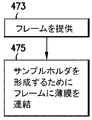
一態様において、図4Eを参照すると、上述のようなワークピース400Aは、自動で(本明細書に記載するように)操作される、自在かつ標準化されたグリッドまたはワークピース構造を提供する一方で、多数の撮像および処理モジュールPMで調べられる試料に必要な薄膜の選択において適応性を提供するように、ベース部材BMAと、複数の交換可能または選択可能な薄膜またはウェブ450A〜450H(例えば、グリッド箔)とを含む。ベース部材BMAは、上述のベース部材BMと実質的に同様であるが、この態様においてベース部材BMAは、堅固な周縁部材BMAPにより囲まれる中心の開口APを有する実質的に堅固な周縁部材BMAPとして提供され、これを形成する(図4F、ブロック473)。一例として、ベース部材BMAは環状を有するものとして図示されているが、別の態様において、ベース部材BMAは任意の適切な幾何学的形状を有することが理解されるべきである。ベース部材BMAおよび薄膜450A〜450Hは、薄膜450A〜450Hのそれぞれが挿入可能であり、例えば、機械的に結合されるかおよび/または化学的に結合されるなど、任意の適切な方法でベース部材BMAに結合されるか、あるいは連結される(図4F、ブロック475)。一態様において、薄膜450A〜450Hは、それぞれのベース部材BMA内に挿入され、薄膜450A〜450H上に圧縮応力を径方向に生じる締り嵌めによってベース部材BMA内に固定される。一態様において、締り嵌めは、薄膜450A〜450Hをベース部材上に適合させる収縮により形成され、逆の場合も同様である。別の態様において、ベース部材および薄膜は一ユニット(例えば、モノリス部材)として形成される。一態様においてベース部材BMAは、以下に記載するものと実質的に同様のリフトアウトワークピース/グリッドを保持するように構成され、リフトアウトワークピース/グリッドは、薄膜450A〜450Hに関して本明細書に記載したものと実質的に同様の方法で、ベース部材BMAに配置される。
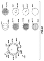
In one aspect, referring to FIG. 4E, a
一態様において、薄膜450A〜450Hは、ベース部材BMAおよび/または開口APの形状に実質的に一致するように成型される(例えば、ベース部材が環状である場合、薄膜は、薄膜がベース部材BMAの開口APに広がるように、円形などを有する)。一態様において、薄膜450A〜450Hは、ベリリウム銅合金またはセラミックから構成されるが、別の態様において薄膜450A〜450Hは、任意の適切な材料から構成される。さらに別の態様において、薄膜450A〜450Hは、サブミリメータ幅のシートであるが、別の態様において薄膜450A〜450Hおよび/またはベース部材BMは、任意の適切な厚さを有する。理解され得るように、薄膜450A〜450Hはそれぞれ、他の薄膜450A〜450Hそれぞれの所定のサンプル保持機構とは別の、異なる所定のサンプル保持機構を有する。例えば、一態様において、所定のサンプル保持機構は、薄膜450A〜450Hに取り付けられる試料サンプル、および/または、試料サンプルに対して行われる撮像処理(例えば、試料サンプルの撮像特徴)に基づく。図4Eに見られるように、所定のサンプル保持機構は、一態様においては、それぞれの薄膜450A〜450Hに形成される1つまたは複数の開口である。例えば、薄膜450A、450Fは、単一の開口401(スロットグリッドを形成するためのスロット開口)、401PE(ホールグリッドを形成するための円形開口)を含んでいるが、薄膜450B〜450Eは、開口のアレイを有する。説明を目的として、薄膜450Bは平行なメッシュグリッドを形成する開口401PAを含み、薄膜450Cは六角形またはハニカムグリッドを形成する開口401PBを含み、薄膜450Dは溝付き/メッシュグリッドを形成する開口401PCを含み、薄膜450Eは正方形のメッシュグリッドを形成する開口401PDを含む。理解され得るように、別の態様において、薄膜450A〜450Eの開口は、試料サンプルを保持および撮像するための任意の適切なグリッドパターンを形成するために、任意の適切な形状を有する。一態様において、薄膜は、例えば、Pioloform(登録商標)、Formvar(登録商標)、Parlodion(登録商標)、および/または、Luxel LUXfilm(登録商標)などの支持フィルムを含む。一態様において、本明細書に記載されるワークピース(400、400A(および薄膜)、400A1〜400A4)は、カーボンなど、有利な電気的または熱的特性を有する任意の適切な被覆により被覆されるが、別の態様において、本明細書に記載されるワークピースは被覆されない。一態様において、薄膜450Gなどの薄膜は、例えば、本明細書に記載される自動化搬送および配置システム100(例えば、ワークピース400が処理され得るように処理モジュールPMに対してエンドエフェクタ101を配置する)の位置合わせまたは設定をもたらすように構成される1つまたは複数の参照基準401PFを含む参照/較正グリッドを形成する。別の態様において、薄膜450Hは、試料サンプルが配置される隙間のない平らな表面(例えば、開口を有さない)。
In one aspect, the
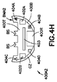
次に図4G〜4Jを参照すると、ワークピース400A1、400A2、400A3、400A4は、上述のワークピース400と実質的に同様であり、上述のワークピース400の特徴を全て含む。この態様において、ワークピース400A1、400A2、400A3、400A4の、それぞれの薄いシート状のベース部材BMA1、BMA2、BMA3、BMA4は、半月形状を有するリフトアウトワークピース/グリッドの形態である。この態様において、各ワークピース400A1、400A2、400A3、400A4は、1つまたは複数のサンプル受容部BSを含み、例えば、半導体の薄板などの試料サンプルや他の適切なサンプルは、ワークピース400A1、400A2、400A3、400A4と一体のユニットを形成するために、結合表面に実質的に直接堅固に結合または取り付けられる(任意の適切な方法で)。
4G-4J, workpieces 400A1, 400A2, 400A3, 400A4 are substantially similar to
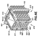
図5A〜5Iを参照すると、開示される実施形態の態様によるカセット102が図示されている。この態様においてカセット102は、長方形形状のカセットフレーム102Fを有するものとして図示されているが、別の態様においてカセット102/カセットフレーム102Fは、他の任意の適切な形状および/または構成を有する。カセットフレーム102Fは、ポケットがカセット102の第1の面102Tからアクセス可能であるようにグリッドに配置される、1つまたは複数のワークピース400保持ステーションまたはポケット500を含む。この態様においてグリッドは、64個の個別のワークピース400を保持するために、8×8列のポケット500を含むが、別の態様においてグリッドは、例えば、128個の個別のワークピースを保持するための8×16列など、任意の適切な数の列および行を有する。一態様において、カセットは、オペレータおよび/または機械が各ポケット500の位置を識別できるように、第1の面102T(または他の任意の適切な場所)に列および行の識別子(例えば、英数字、バーコードなど)も含む。例えば、列は、連続する一連の番号1〜8によって識別され、行は、連続する一連の文字A〜Hによって識別される(逆の場合も同様)が、別の態様においては、任意の適切な識別子が用いられ得る。カセット102は、カセットを識別するための、任意の適切な機械が読み取り可能なおよび/またはヒトが読み取り可能なマークも含む。例えば、カセットは、横辺SL1、SL2および縦辺SL3、SL4を定めるために、縦軸LA1および横軸LA2を有する。一態様において、第1の面102T(そこからワークピースがアクセスされる)は、任意の適切な数のバーコード501Aおよびヒトが読み取り可能なマーク502A(連続番号など)などの、読み取り可能なデータ記憶媒体を含み、これは一態様においては、ワークピース400に関して上述したものと実質的に同様である。理解され得るように、一態様においては、長手方向の表面や縦辺SL4などの他の表面も、カセット102が例えばマガジン105内に位置付けられている間、カセット102が識別されるか識別可能であるように、同様のバーコード502Bおよびヒトが読み取り可能なマーク502Bを含む。理解され得るように、バーコード501Aおよびヒトが読み取り可能なマーク502Aは、カセットおよびカセット上に保持されるワークピース400のアレイを、原料物質構成(原料物質構成は、本明細書にさらに詳細に記載される、例えば、図9参照)に関連付ける、カセット識別データを含む。一態様において、カセット識別子501A、502Aは、RFIDチップ、Bluetooth(登録商標)送信機、または、例えば自動化搬送および配置システム100内、および/または、ワークピース処理システムまたは設備100PSの任意の適切な部分内に置かれる、任意の適切なスキャナSCRによって読み取られるように構成される他の適切な無線識別子などの、アクティブまたはパッシブな電子チップの形態である(以下により詳細に記載、図11および11Aを参照)。
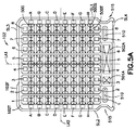
5A-5I, a
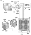
理解され得るように、図9を参照すると、一態様において、ワークピース400〜400nは、所定の順序でカセット102AAのそれぞれのポケット500内に配置されるか、あるいは置かれ、この順序は、例えば、ポケット500のアレイにおけるワークピース400のアレイの所定の配置、ワークピース上のサンプル1070S1〜1070Snが取られた試料/構造体1070の構造体STR、または他の任意の適切な基準の、1つまたは複数に対応する。一態様において、ワークピースの所定の順序(ゆえに、ワークピース上に位置付けられる試料の所定の順序)は、本明細書に記載されるように、カセット120へのワークピースのアレイの各ワークピースの装着と同時に定められる。図9に見られるように、構造体または試料1070は、サンプル1070A〜1070nに分割され、これらのサンプル1070A〜1070nは、それぞれのワークピース400A〜400n上に配置される。これらのワークピース400A〜400nは、例えば、試料1070の構造を表す所定の順序で1つまたは複数のカセット102AAに配置される。また理解され得るように、一態様において、サンプル1070S1〜1070Snまたはワークピース400A〜400n(例えば、サンプルのバッチ)の所定の順序は、1つまたは複数のカセット102がマガジン105AA内に保持されている場合などは、2つ以上のカセット102AA〜102CCにわたり、処理されるべきサンプル1070S1〜1070S2またはワークピース400A〜400nのバッチは、マガジン105AA内にカセット102AA〜102CCの1つまたは複数を含む(例えば、マガジン105AAは1つまたは複数のバッチを保持し、バッチは、ワークピース識別マークおよびカセット識別マークの1つまたは複数により識別され、例えば、共通の構造または試料に該当する)。別の態様において、サンプル1070S1〜1070Snの順序を含むサンプルのバッチは、複数のマガジン105AA〜105BBにわたる。一態様において、バッチ(例えば、バッチに含まれるワークピース/サンプル、および/または、カセット)は、ワークピース識別マークおよび/またはカセット識別マークによってデータ構造DS(以下にさらに詳細に記載)に定められる(例えば、ワークピース/サンプルが属するバッチは、それぞれのワークピース/サンプルの識別マークに含まれる)。一態様において、データ構造は、制御装置199(例えば、検査室情報管理システムLIMSに含むための)のメモリ199M内にあるか、メモリ199M内で具現化され、例えば、XMLデータベース、リレーショナルデータベース、オブジェクトリレーショナルデータベース、または、本明細書に記載されるような情報を記憶するのに適切な他の任意のデータベースまたはデータ構造として実装される。
As can be appreciated, referring to FIG. 9, in one aspect, the workpieces 400-400n are placed or placed in
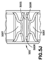
一態様において、カセット102のポケット500は、テーパー面またはガイド部材500Tにより構成される。一態様において面500Tは、ワークピース400を保持スロット500S内に導く。別の態様において、テーパー面またはガイド部材500Tは、ワークピース400を把持するために保持場所内へのグリッパのアクセスを可能にし(図5I参照)、ワークピース検出部材280によってスロット500S内のワークピースを見ることを可能にするように構成される。理解され得るように、一態様において、図5Dおよび5Jも参照すると、ポケット500は、ポケット500の保持スロット500Sおよび/または面500Tの1つまたは複数と分離し離れているか、または一体である、任意の適切なワークピース保持機構または構造500Rを含む。ワークピース保持機構500Rは、ワークピースが、例えば加速、重力または衝撃によりそれぞれのポケット500から落下することを実質的に防ぐ一方で、エンドエフェクタ101、301によるポケット500からの取り出しおよびポケット500への挿入は可能にする(例えば、保持機構500Rは妨害しない)ように構成され得る。ワークピース保持機構500Rの例としては、これらに限定されないが、グリップテープ、感圧接着剤、シート接着剤、供給される液体接着剤(保持機構を形成するために乾燥または硬化する)、弾性部材、静電保持部材、クリップ、静摩擦生成表面(例えば、カセット表面などのベース部材上に形成される、被覆剤またはアップリケ/テープ、表面パターン)、上に摩擦/静摩擦グリッドが形成される滑りにくい表面、または他の任意の適切な保持部材が挙げられる。理解され得るように、保持機構500Rは、ワークピース400上に残る部分が全くないようにワークピース400をそれぞれのポケット500から取り出すために、エンドエフェクタ101または手動で操作されるピンセットがポケット500内に挿入されることを可能にしつつ、任意の方向における、例えば数Gまでの負荷でポケット500にワークピース400を保持する。また理解され得るように、ワークピース保持機構500Rは、ワークピース400がポケット500内に配置されている間、ワークピース400の回転の位置/向きを維持するように構成される。例えば、ワークピースが所定の回転方向でポケット内に挿入されると(任意の適切なアライナ(一態様においては、処理モジュールPMおよび/または自動化搬送および配置システム100の外部にある)により位置合わせされた後などに)、この回転方向は、処理モジュールPMおよび/または自動化搬送および配置システム100内で維持されるので、プリアライナ103を用いたワークピース400の位置合わせは省略でき、処理モジュールPMにおけるスループットを増加させる。別の態様において、ワークピース400がプリアライナ103により位置合わせされる場合、この回転方向は、カセット102内でのワークピースの搬送中、ワークピース保持機構500Rによってポケット500内で維持される。一態様において、ワークピース保持機構500Rは、高真空に適合しており、ここで高真空とは、例えば、10-5トール以下である。理解され得るように、カセット102は、ポケット500(およびその中のワークピース)とエンドエフェクタ101のグリッパとの間の相対的な配置(例えば、位置合わせ)を可能にするために、カセット102の1つまたは複数の表面上に任意の適切な運動学的配置機構を含み得る。例えば、第1の表面または面102Tは、1つまたは複数の運動学的凹部510(または他の適切な機構)を含み、第2表面または面102Bは、マガジン105からおよびマガジン105へのカセット102の自動化された取り出しおよび配置のために、カセットシャトル126(図1D)のグリッパ126Gとインターフェースをとる凹部511(例えば、縦辺SL3、SL4の1つまたは複数に配置するか、それらに隣接する)を含む。一態様において、カセット102は、マガジン105からおよびマガジン105へのカセット102の手動の取り外しおよび挿入を可能にするために、例えば、横辺SL1、SL2上にも凹部515を含む。別の態様においては、カセット102の任意の適切な場所に把持機構515、510、511が位置付けられる。一態様において、カセット102の横辺SL1、SL2は、以下に記載されるように、マガジン105とインターフェースをとるように任意の適切な方法で構成されるので、カセットは、所定の向きでマガジン105内に挿入される。一態様において、横辺SL1、SL2は、マガジン105のテーパー表面600Tを係合するためにテーパー状にされる(図6A〜6E)ので、カセットは、単一の向きでのみマガジン105内に挿入され得る。別の態様において、カセット102は、カバー590(後述)を係合し、カバー590は、カバーおよびカセットの両方が、所定の向きでのマガジン内へのカセット/カバーアセンブリの挿入をもたらす入れ子状の「ポカヨケ(poka-yoke)」または位置決定機構を有するように、マガジンを係合する。一態様において、凹部520は、カセット102の第2の面102B上に位置付けられ、RFIDチップなどの任意の適切な無線識別、または他の無線識別、トランスポンダまたはテレメトリユニットを含む。別の態様において、無線識別は、任意の適切な方法で、任意の適切な場所でカセットに取り付けられる。
In one embodiment, the
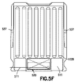
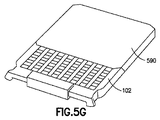
図5Hおよび5Gも参照すると、カセット102は、一態様においては、例えばカセット102の搬送および/または保管中に、ポケット500内部にワークピース400を固定あるいは保持するための、取り外し可能なカバー590を含む。カバー590は、縦辺592、593および横辺594、595を画定するように、縦軸LA3および横軸LA4を有する。カバー590の少なくとも一方の縦辺593は、カバー590がカセット102の上部をスライドできるように開放している。例えば、カバーの辺593は、図5Gに見られるように、カセット102の縦辺SL3からカセットの縦辺SL4に向けてカバー590を移動させることにより、カセット102の上部をスライドされるので、カバー590の保持表面591は、ワークピースをそのそれぞれのポケット500に保持するために、カセット102の第1の面102Tに隣接して配置され、また第1の面102Tに広がる。理解され得るように、カバーの横辺594、595は、カセット102の横辺SL1、SL2の周りに延びるか、包み込む(例えば、マガジン内のカセットを配向するために横面SL1、SL2の角度にしたがう)ので、延伸部材594M1、594M2、595M1、595M2は、カバー590がカセット102から分離することを実質的に防ぐために、第2の表面102Bの部分を越えて延びる。少なくとも1つの延伸部材594M1、594M2、595M1、595M2は、カセット102とカバー590との間の相対的な長手方向の動作を実質的に防ぐために、カセットの第2の面102Bに配置される突出部分537と係合するように構成される弾性部材SPR1、SPR2を含むので、カセット102はカバー590内に保持される。弾性部材SPR1、SPR2の保持力は、本明細書に記載されるように、カセットシャトル126がカバー590、すなわちマガジン105からカセット102を除去および挿入することを可能にしつつ、カセットをカバー内に保持するような保持力である。本明細書に記載されるように、カバー590は、カセット102およびカバー590アセンブリをマガジン105内に保持し、またカセットシャトル126がマガジン105からカセット102を取り外すときには、カバー590をマガジン105内に保持するために、縦辺592の一方にロック部材597も含む。
Referring also to FIGS. 5H and 5G, the
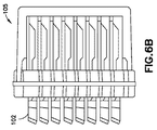
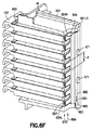
図6A〜6Fを参照すると、開示される実施形態の態様によるマガジン105が示されている。マガジン105は、1つまたは複数のカセット102と一緒に、本明細書に記載されるようにカセット102のポケット500へおよびポケット500からのワークピース400の手動の移送または自動化された移送のために構成される、ワークピース400の保管システムを形成する。マガジン105は、1つのマガジンに1024個のワークピースというワークピース保持機能を可能にするために、例えば8個のカセットなど、少なくとも1つのカセット102を保管するように構成され、この場合カセットは、8×16列のポケットを含む。別の態様においてマガジンは、8個よりも多いかまたは少ないカセットを保持し、カセットと組み合わせた任意の適切なワークピース保持機能を有する。マガジン105は、一体アセンブリとしてカセット102を含み支持するフレーム601を含む。一態様において、フレームは、ドアまたはカバーにより密閉されるように構成され、キャビティの任意の適切な環境(例えば、真空環境、大気環境など)での保管のためにカセットが挿入されるキャビティを形成する。フレーム601は、搬送シャトル120MSに対してマガジンを位置付けるため、および、任意の適切な自動化マガジン搬送部を用いた、例えばチャンバ120C内へのマガジンの自動装着のために、上述のような搬送シャトル120MSの対応する運動学的機構とインターフェースをとる任意の適切な運動学的機構610〜612(および/または、運動学的機構610〜612と既知の関係で配置される自動化された操作機構AF)を含む。一態様において、運動学的機構は、ピンおよび凹部であるが、別の態様において運動学的機構は、任意の適切な位置付け機構である。一態様において、運動学的機構610〜612は、マガジン105が、搬送シャトル120MS上に装着されるときには単一の所定の向きのみを有するようにも構成される。一態様において、フレーム601は、マガジン105の手動または自動の識別のために、任意の適切な識別マーク(例えば、バーコードであるか/バーコードと実質的に同様の読み取り可能なデータ記憶媒体、ヒトが読み取り可能なマーク、RFID、上述のトランスポンダおよびテレメトリ装置)を含む。一態様において、識別マーク620は、マガジンおよびその中に配置される1つまたは複数のカセット上に保持されるワークピース400のアレイを、原料物質構成(原料物質構成は、本明細書にさらに詳細に記載される、例えば、図9参照)に関連付ける、マガジン識別データを含む。一態様において、マガジン識別子620は、RFIDチップ、Bluetooth(登録商標)送信機、または、例えば自動化搬送および配置システム100内、および/または、ワークピース処理システムまたは設備100PSの任意の適切な部分内に置かれる、任意の適切なスキャナSCRによって読み取られるように構成される他の適切な無線識別子などの、アクティブまたはパッシブな電子チップの形態である(以下により詳細に記載、図11および11Aを参照)。
6A-6F, a
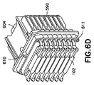
上述のように、マガジン105は、1つまたは複数のカセット保持ステーション600を含む。各カセット保持ステーション600は、カセットおよびカバーアセンブリの断面に適合する側面600Tを含むので、カセットおよびカバーアセンブリは、単一の所定の向きでのみマガジン105内に挿入され得る。また上述のように、各カセット102のカバー590は、マガジン105内にカバー590(およびカセット102)を保持するためにマガジン105の対応するロック機構と係合するロック部材597を含む。例示のみを目的として、フレーム601は、保持またはラッチプレート604が挿入されるトラック670を形成する。トラック670は、フレーム601上に配置されるので、カバーの縦辺592は、カバーおよびカセットアセンブリがそれぞれのカセット保持ステーション600内に挿入されるときには、トラックに隣接して配置される。トラック670は、1つまたは複数の支持面601LSおよび対向する保持部材671を含む。1つまたは複数の支持面601LSおよびそれぞれの保持部材671は離間されているので、保持プレート604は、1つまたは複数の支持面601LSとそれぞれの保持部材671との間に挿入され得る。保持プレート604は、トラック670への保持プレートの挿入およびトラック670からの保持プレートの除去のために、保持プレート604のスライド操作を可能にするよう構成されるハンドル604Hを含む。また保持プレート604は、保持プレート604がトラック670内に挿入されると、カバー590のロック部材597と係合するロック部材604Lを含む。例えば、保持プレート604は、1つまたは複数の支持面601LSとそれぞれの保持部材671との間で、トラック670内へと矢印699の方向にスライドあるいは挿入される。保持プレート604のロック部材601Lは、挿入方向699に向く一方で、カバー590のロック部材597は、挿入方向699とは反対方向に向くので、保持プレート604がトラック内に完全に挿入される(以下に記載)と、ロック部材597は実質的に同時に対向するロック部材601Lと係合する。
As described above, the
一態様において、保持プレート604は、1つまたは複数の弾性部材680を含み、フレーム601は1つまたは複数の戻り止め681およびカム部材682を含む。弾性部材680は、矢印699の方向に移動するとき(例えば、トラックへの保持プレートの挿入中)はカム部材682と係合するように構成されるので、弾性部材680は、弾性部材680が戻り止め681に係合されているときに保持プレート604を閉鎖状態に維持する(例えば、カバーは保持プレートによってしっかりと保持される)ために、戻り止め681と係合するようカム682を通過する。弾性部材は支持面601LSに向かって付勢されるので、弾性部材680は戻り止め681と係合して、実質的にトラック670からの保持プレート604の取り外しを防ぐ。保持プレート604は、トラック670から保持プレート604を取り外すため、および/または、フレームマガジン105からのカバー590の離脱のために、弾性部材680を戻り止め681およびカム部材682を越えて上昇させ、戻り止め681およびカム部材682の上部での弾性部材680の通路を可能にするための、離脱ツール(図示せず)が挿入されるスロットまたはチャネル683を含む。一態様において、フレーム601は別の戻り止め681’およびカム部材682’も含み、保持プレート604は、例えば弾性部材680および戻り止め681が非係合であるときに、保持プレート604が1つのカセットピッチPよりも多く移動することを実質的に防ぐように構成される別の弾性部材680’も含む。理解され得るように、保持プレート604は、保持プレート604を取り外し、保持プレート604がトラック670から完全に取り外されるように、弾性部材680’を戻り止め681’およびカム部材682’を越えて上昇させ、戻り止め681’およびカム部材682’の上部での弾性部材680’の通路を可能にするための、スロットまたはチャネル683と同様の、離脱ツール(図示せず)が挿入され得るスロットまたはチャネル683’を含む。
In one aspect, the
カバー590、カセット102およびマガジン105は、任意の適切な材料から構成される。一態様において、カバー590、カセット102およびマガジン105は、真空環境での使用のために、真空環境に適合した材料から構成される。別の態様において、カバー590、カセット102およびマガジン105は、任意の適切な環境での使用のために構成される。
一態様において、上述の、ワークピース400の1つまたは複数の適切な構造体または識別マークは、それぞれのワークピース400上に保持されるサンプルの物理的な表示である。例えば、適切な構造体または識別マークの1つまたは複数は、一態様においては任意の適切な制御装置199(以下にさらに記載)のメモリ199Mにあるデータ構造DS(図1A、以下にさらに記載)に関連付けられる固有の識別子である。
In one aspect, the one or more suitable structures or identification marks of the
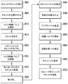
次に図1Aおよび7A〜7Fを参照すると、開示される実施形態の態様にしたがって、自動化搬送および配置システム100の例示的な動作が説明される。チャンバ125Cは、処理モジュールPMの圧力と実質的に等しい圧力までポンプされ、1つまたは複数のカセット102を保持するマガジン105は、ロードロック120の密閉可能なチャンバ120C内に挿入される(図8、ブロック800)。例えば、ドア120Dは開放され、マガジン105は、手動または任意の適切な搬送の自動化など、任意の適切な方法で搬送シャトル120MS上に運動学的に配置される。ドア120Dは、密閉可能なチャンバ120Cを密閉あるいは隔離するために閉鎖される。ロードロックは、チャンバ125C内の圧力と適合するか実質的に等しくなるようにポンプされ、搬送シャトル120MSは、バルブV2Gの上部で所定のカセット102Aを位置合わせするために移動させられる(図8、ブロック805)。バルブV2Gは開放されているので、チャンバ120Cの内部はチャンバ125Cの内部と通じている(図8、ブロック810)。カセットシャトル126は、所定のカセット102Aを運動学的に係合するために、矢印700の方向に移動する(図8、ブロック815)。所定のワークピースがワークピース配置ユニット104の動作範囲内で位置付けられるように、マガジン105(およびそのそれぞれのカバー590)からカセット102Aを取り出すために、カセットシャトル126は矢印701の方向に移動する(図8、ブロック820)。理解され得るように、一態様において、ワークピース配置ユニット104に対するカセット102A(およびその中のワークピース)の配置は、マガジンシャトル120MS上に保持されるマガジン105の1つまたは複数のカセット102上に保持されるワークピースのバッチの、所定のバッチワークピース処理順序(データ構造DSにより、またはデータ構造DSにおいて定められる、図1A参照)に対応する。バルブV2Gは閉鎖される(図8、ブロック825)。
With reference now to FIGS. 1A and 7A-7F, exemplary operations of the automated transport and
ワークピース配置ユニット104は、カセット102からワークピース400を取り出すようにエンドエフェクタ101を配置するため、方向703、704、705(例えば、X方向、Y方向および傾動方向)の1つまたは複数に移動し(図8、ブロック830)、カセット102からワークピースを取り出す(図8、ブロック835)。カセットシャトル126は、カセットを緩衝位置に移動させるために矢印701の方向にさらに移動し(図8、ブロック840)、ワークピース配置ユニット104は、ワークピースを所定の向きに位置合わせするため、プリアライナステージ103上にワークピース400を配置するよう方向702、704、705の1つまたは複数に移動する(図8、ブロック845)。理解され得るように、一態様において、プリアライナステージ103から得られる、ワークピース400の位置合わせについてのデータは、データ構造DSに含めるために任意の適切な方法で制御装置199に伝えられる。一態様において、プリアライナステージ103は、例えばプリアライナステージがカセットシャトル126から独立してフレーム140Fに可動に取り付けられると、矢印701の方向に後退される(図8、ブロック850)。プリアライナステージ103がカセットシャトル126に取り付けられる(すなわち、プリアライナステージおよびカセットシャトルはユニットとして移動する)別の態様においては、カセットシャトルはワークピースの位置合わせの後に後退される。さらに別の態様において、プリアライナステージ103はZ軸に沿って静止しており、後退されなくてもよい(例えば、プリアライナステージは、ワークピース配置ユニット104が処理モジュールPMにアクセスすることを可能にするよう配置される)。バルブV1Gは、ポート125Pを通した処理モジュールPMへのアクセスを可能にするために開放される(図8、ブロック855)。
処理のために処理モジュールPM内にワークピース400を配置し(図6、ブロック860)、一態様においては、ワークピース400はエンドエフェクタ101により保持されており、また別の態様においては、処理モジュールPMの配置ステージPS上にワークピース400を配置するため、ワークピース配置ユニット104は、方向703、704、705(例えば、X方向、Y方向、Z方向および傾動方向であり、傾動方向は、開示内容全体が参照により本明細書に組み込まれる、2014年11月11日に出願された代理人整理番号が1210P015007−US(PAR)の「Workpiece Transport and Positioning Apparatus」と題された米国特許出願に記載の、第1の傾動軸TXおよび第2の傾動軸TX2を含む)の1つまたは複数に移動する。例えば、ワークピース400が配置ステージPS上で処理され、配置ステージPSにより配置される(例えば、処理中に)場合、ワークピース配置ユニット104は、配置ステージPS上にワークピース400を置くので、配置ステージPSが処理のためにワークピースを処理モジュールPM内に配置する。一態様において、ワークピースの処理命令は、例えば処理モジュール内でのワークピースの移動(一態様においては、ワークピースが位置付けられるエンドエフェクタの移動を通した移動、また別の態様においては、ワークピースが位置付けられる配置ステージPSの移動を通した移動)を含む、処理モジュールPMによるワークピース400の処理、および処理モジュールPMによるワークピース400の処理をもたらすために、データ構造DSから制御装置199により処理モジュール(および/または、処理モジュールのオペレータ)に伝えられる。理解され得るように、自動化搬送および配置システム100、特にワークピース配置ユニット104は、対物レンズチャンバ8CH(上述)と共通の大気を共有する、対物レンズチャンバの外部のワークピース/試料取り出し位置を有し、自動化搬送および配置システム100の駆動セクションは、取り出し位置(例えば、ワークピース保持ステーション176)から、例えば、トモグラフィー検査位置(例えば、処理位置177)へのエンドエフェクタの移動をもたらし、独立した複数自由度により、試料のトモグラフィー検査の配置を一度の移動でもたらす。
The
一態様において、ワークピース400の処理中に得られた処理データは、データ構造DSに含むために、処理モジュールPMによって制御装置に伝えられる。ワークピース配置ユニット104は、処理モジュールPMから後退し、バルブV1Gは閉鎖される(図7F)。カセットシャトル126は、カセット102を配置するために矢印701Aの方向に移動するので、ワークピース配置ユニット104は、ワークピースが取り出されたカセット102内のポケット500にワークピース400を戻す(図8、ブロック865)。理解され得るように、一態様においては、カセット102がマガジン105に戻される前に、カセット102により保持される追加のワークピースが、例えば上述の所定のバッチワークピース処理順序で処理される。バルブV2Gは開放され、カセットシャトル126はカセット102をマガジン105に戻し、バルブV2Gは閉鎖され、搬送シャトル120MSはチャンバ120Cからのマガジンの取り外しのために、所定の位置へと移動する(図8、ブロック870)。別の態様において、搬送シャトル120MSは、別のワークピース(または複数のワークピース、例えば、異なるカセットにより保持されるワークピースのバッチ)の処理のため、および/または、2つ以上のカセット102に画定されるワークピースのバッチの処理を継続するため、異なるカセット102をバルブV2Gと位置合わせする。
In one aspect, processing data obtained during processing of the
図9を参照すると、上述のように、制御装置199は、1つまたは複数のワークピース上に位置付けられる試料の追跡および分析をもたらすデータ構造DSを含む。上述のように、制御装置199は、1つまたは複数のワークピース上に位置付けられる試料の追跡および分析をもたらすデータ構造DSを含む。一態様において、制御装置199は、データ構造DSを生成および維持するように構成されるニューラルネットワークおよび/またはステートマシンを含むが、別の態様において制御装置は、データ構造DSを生成および維持するように構成される任意の適切な処理/プロセッサを含む。一態様において、ニューラルネットワークおよび/またはステートマシンは、本明細書に記載されるように、データ構造DS内の情報に基づいて、自動化搬送および配置システム100の動作および処理フロー(例えば、どのワークピースがどの順番でどの処理モジュールに運ばれるかなど、自動化搬送部のルーティング、処理のスケジューリング、および/または、ワークピースの処理順序の制御、など)を制御するように構成される。データ構造は、本明細書に記載されるように、サンプルがワークピース上に置かれた時点からサンプルの最終的な分析結果を得るまで、ワークピース400が、例えば検査室または他の設備(本明細書に記載)のどこにあるかについてのデータ、ならびに、サンプルに行われる処理についてのデータを含む。一態様において制御装置199は、ユーザが、分析結果、または検査室または他の設備内のサンプルの場所を含むデータ構造DS内の他の任意のデータを見ることができるように構成されるユーザインターフェースUIを含む。
Referring to FIG. 9, as described above, the
一態様においてデータ構造DSは、自動化搬送および配置システム100、処理モジュールPM、またはワークピース/試料を保管、搬送および/または分析するように構成される他の任意の適切な検査室装置を通して処理される、ワークピース/試料のバッチに関する情報を含む。理解され得るように、生物学的構造体、金属構造体、半導体構造体など、任意の適切な構造体または試料1070(例えば、原料物質)は、任意の適切な方法でサンプルへと分割され、各サンプルは、任意の適切な方法でそれぞれのワークピース400に取り付けられる。各サンプルはワークピース400と関連付けられ(例えば、試料はワークピースに取り付けられる)、各ワークピースはカセット102と関連付けられ、各カセットはマガジン105と関連付けられ、ワークピース400の各処理ステップでデータ構造DSが更新されるので、データ構造DSは、サンプルの1つまたは複数の所定の特性/物理的属性をワークピース400の固有の識別子に関連付ける。理解され得るように、データ構造DSは、共通の構造体1070から取られた試料をそれぞれに対しても関連付けるので、個別のサンプル(ワークピースに関連付けられる)は全体として追跡および分析され、その結果、構造体1070の特性の自動判定は、構造体1070全体に対してなされる(以下にさらに詳細に記載)。理解され得るように、視覚システム(本明細書に記載のセンサを含む)は、処理全体にわたってワークピース400、カセット102およびマガジン105を識別するので、処理ステップおよび他の集められた情報は、本明細書に記載されるように、データ構造DS(および検査室情報管理システムLIMS)において、対応するワークピース400(およびその上の試料)に関連付けられる。
In one aspect, the data structure DS is processed through the automated transport and
また図1を参照すると、理解され得るように、ワークピース処理システムまたは設備100PSにわたるワークピース400(およびその上の試料サンプル)の移動は、上述の自動化搬送および配置システム100の、駆動軸(例えば、駆動部またはモータ)A1L、A2L、A3L、A4L、A5L、A6L、A7R、A8R、A15Rなど、1つまたは複数の搬送部の1つまたは複数の駆動軸によってもたらされる。駆動軸A1L、A2L、A3L、A4L、A5L、A6L、A7R、A8R、A15Rはそれぞれ、データ構造DSおよび/または検査室情報管理システムLIMS(一態様においてはデータ構造DSを含む)におけるワークピースの状態(例えば、位置状態、処理状態、ワークピースのバッチ内の順序の状態、向きの状態など)を更新するために、ワークピース400(およびその上の試料サンプル)の位置に関するデータを制御装置199に与える。例えば、マガジン105は、任意の適切な方法(自動化搬送または手動)でロードロック120内に置かれ、スキャナCAM4などの任意の適切なスキャナは、マガジン105の識別マークを読み取り(図10、ブロック2000)、ロードロック120内に位置付けられている間のマガジン105内に配置されるワークピース400の状態を更新するために、制御装置199に適切な信号を送る(図10、ブロック2005)。マガジン105内のカセット102を、例えばポート120Pと位置合わせするために、駆動軸A1Lはマガジン105を移動させる(図10、ブロック2010)。一態様において、駆動軸A1Lは、所定のカセット102がポート120Pと位置合わせされたことを示す適切なエンコーダまたは他の位置データを制御装置199に送り、制御装置199は、例えば、密閉可能なチャンバ125C内に装着されるために配置されている、所定のカセット102のワークピース400の状態を更新する(例えば、データ構造DSにおいて)(図10、ブロック2015)。一態様において、スキャナCAM1などの任意の適切なスキャナはカセットの識別マークを読み取り、カセット内のワークピースの状態を更新するために制御装置199に適切な識別データを送る。理解され得るように、一態様において、データ構造DSの更新をもたらすために、駆動軸A1L、A2L、A3L、A4L、A5L、A6L、A7R、A8R、A15Rによって制御装置199に送られたデータ(および/または、センサCAM1〜CAM5によって送られたデータ)は、任意の適切な方法で検査室情報管理システムLIMSにも入力される(例えば、制御装置およびデータ構造は、一態様においては検査室情報管理システムLIMS内に組み込まれているか、有線または無線接続などを通した任意の適切な方法で検査室情報管理システムLIMSに接続される)。
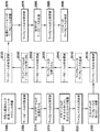
Referring also to FIG. 1, the movement of the workpiece 400 (and the sample sample thereon) across the workpiece processing system or facility 100PS is understood by the drive shaft (eg, the automated transfer and
駆動軸A2Lは、ポート120Pを通してマガジン105から所定のカセット102を取り出し/配置するために、カセットシャトル126を移動させる(図10、ブロック2020)。駆動軸A2L(およびカセットシャトルのグリッパの駆動軸)は、制御装置199に適切なエンコーダまたは他の位置データを送り(例えば、データ構造DSにおいてワークピースの状態を更新するため)、これは所定のカセット102(およびその中に位置付けられるワークピース)がカセットシャトル126によって把持され、所定の位置でZ方向に配置されることを示すので、1つまたは複数のワークピース400はカセット102から取り外され得る(図10、ブロック2025)。一態様において、エンドエフェクタ101上のセンサCAM2および/またはセンサ281などの1つまたは複数のセンサは、カセット102および/またはワークピース400の位置を確認し、および/または、識別をもたらし(例えば、1つまたは複数のワークピースの処理を追跡するため)、および/または、以下に記載されるように、エンドエフェクタの自動の配置およびエンドエフェクタによるワークピースの自動の捕捉をもたらす。駆動軸A3L、A4L、A5L、A6L、A7R、A15Rの1つまたは複数は、カセット102からのワークピース400の取り出し/配置のために、エンドエフェクタ101の移動をもたらす(図10、ブロック2030)。上述の方法と実質的に同様の方法で、エンドエフェクタ101は、駆動軸A3L、A4L、A5L、A6L、A7Rの1つまたは複数により制御装置199に任意の適切なエンコーダまたは他の位置データが送られる(例えば、データ構造DSを更新するため)ように、カセット102のポケット500から所定のワークピースを取り出し/配置するように配置され、これは、所定のワークピース400がカセットから取り出され、またはカセットに置かれたことを示し、また所定のワークピース400の、例えばX、YおよびZ方向の1つまたは複数における位置を示す(図10、ブロック2035)。上述のように、一態様において、エンドエフェクタ281および/または離れたエンドエフェクタセンサCAM2は、少なくとも、カセット102に対する所定のワークピース400の取り出し/配置を確認する。一態様において、センサ281またはセンサCAM2は、データ構造DSにおいてワークピースに関する処理情報を更新するために、ワークピースが取り出されていることを識別する。一態様において、制御装置199は、ワークピース400(およびその上の試料)の電子顕微データを、ワークピース400の識別マークに関連付ける。一態様において、各ワークピース400の識別マークは、処理モジュールPMによりもたらされる、試料の、所定のグリッド/ワークピースのバッチ走査順序に関連付けられ、ワークピースは、カセット102においてワークピースのアレイで配置されている。一態様において、所定のグリッド/ワークピースのバッチ走査順序は、自動化搬送および配置システム100への、カセット102の装着(例えば、ワークピース処理の順序)および/またはマガジン105の装着(例えば、カセット処理の順序および各カセットのワークピース処理の順序)により自動的に決定される。一態様において、ワークピース400の識別マークは、ワークピースのバッチ上の試料が作製された原料物質構成を示す(図9参照)。
The drive shaft A2L moves the
一態様において、エンドエフェクタ101上のセンサ281および/または離れたエンドエフェクタセンサCAM1〜CAM5は、エンドエフェクタ101と所定の標的(例えば、把持されるべきワークピース400、カセット102のポケット500および/またはプリアライナステージ103などの、ワークピース保持位置、処理モジュールPM内のエンドエフェクタ101/ワークピースの位置など)との間の相対的な位置データを制御装置199に与える。制御装置199は、エンドエフェクタ101と標的との間の相対的な位置決定を行うなどして、相対的な配置データに基づくエンドエフェクタ101(例えば、本明細書に記載のような)の移動を導くように構成されるので、エンドエフェクタは、例えばエンドエフェクタ101によるワークピース400の自動の捕捉/解放、および/または、エンドエフェクタ101による所定の位置へのワークピース400の自動の配置をもたらすために、自動的に移動/配置される(例えば、エンドエフェクタと標的との間の相対的な位置を変更する)。理解され得るように、相対的な位置データは、一態様においては、データ構造DSにおけるワークピース400の状態(例えば、処理および/または位置の状態)の変更をもたらす。例えば、センサ281、CAM1〜CAM5の1つまたは複数は、所定のワークピース400を保持するカセット102のポケット500だけでなく、エンドエフェクタ101も見る。制御装置199は、ワークピース400および/またはポケット500とエンドエフェクタとの間の相対的な位置に関して決定し、その相対的な位置に基づいて、制御装置199は、カセット102から所定のワークピースを取り出すため/カセット102に所定のワークピースを配置するため、エンドエフェクタの移動をもたらすように、駆動軸A3L、A4L、A5L、A6L、A7R、A15Rに適切な制御命令を送る。理解され得るように、一態様において、エンドエフェクタとワークピース、ワークピース保持位置または処理位置との間の相対的な位置決定は、本明細書に記載されるようなエンドエフェクタの移動をもたらす一方で、別の態様においてエンドエフェクタの移動は、駆動軸のエンコーダデータを通すなど、任意の適切な方法でもたらされる。
In one aspect, the
カセット102から所定のワークピース400が取り外されると、上述のように、ワークピースは、一態様においては上述の方法と実質的に同様の方法で、エンドエフェクタ101によりプリアライナステージ130上に置かれる(図10、ブロック2040)。ここで駆動軸A3L、A4L、A5L、A6L、A7R、A15Rは、所定のワークピースがプリアライナステージ103上に置かれたことを示す適切なエンコーダまたは他の位置データを制御装置199に送るので、ワークピースの状態はデータ構造DSにおいて更新される(図10、ブロック2045)。プリアライナの駆動軸A8Rは、ワークピースの位置合わせをもたらし(図10、ブロック2050)、所定のワークピースが所定の処理方向に向けられたことを示す適切なエンコーダまたは他の位置データを制御装置199に送り、ワークピース400の状態はデータ構造DSにおいて更新される(図10、ブロック2055)。理解され得るように、センサ281および/またはCAM1〜CAM5などの視覚システムは、一態様においては、ワークピース400の位置を確認し(および/または識別し)、および/または、データ構造DSにおけるワークピースの状態を更新するために、制御装置に位置データ(駆動軸データに替えて、またはそれに加えて)を提供する。制御装置199は、プリアライナステージからのワークピース400の取り出しをもたらすように駆動軸A3L、A4L、A5L、A6L、A7R、A15Rに命令し(図10、ブロック2060)、ワークピースの状態は、駆動軸および/または視覚システムによって提供されるデータに基づき更新される(図10、ブロック2065)。
When a
制御装置199はカセットシャトル126の駆動軸A2Lに、カセット102をZ方向に移動させるよう命令するので、ワークピース配置ユニット104は処理モジュールPMへのアクセスを有する。制御装置199は、ポート125Pの開放を命令し、処理モジュールPM内へのエンドエフェクタ101の自動の配置をもたらすように駆動軸A3L、A4L、A5L、A6L、A7R、A15Rに命令するので、エンドエフェクタ上に保持されるワークピースは、処理モジュールPM内の所定の処理位置に配置される(図10、ブロック2070)。上述の方法と実質的に同様の方法で、駆動軸A3L、A4L、A5L、A6L、A7R、A15Rおよび/または視覚システム(センサ281および/またはCAM1〜CAM5など)は、所定のワークピース400が処理モジュールPM内の所定の位置に位置付けられていることを示す適切なエンコーダまたは他の位置データを制御装置199に送るので、ワークピースの状態はデータ構造DSにおいて更新される(図10、ブロック2075)。
Since the
一態様において、ワークピース配置ユニット104による処理モジュール内へのワークピース400の移動は、上述の方法と実質的に同様の方法で相対的な位置データによって自動的にもたらされるか、および/または、駆動軸A3L、A4L、A5L、A6L、A7R、A15Rから制御装置199に受け取られたデータによって自動的にもたらされる。理解され得るように、ワークピースは、ワークピース上の試料サンプルの撮像をもたらすために任意の適切な方法で処理中に処理モジュール内で移動させられ(図10、ブロック2080)、ワークピースの状態は、その移動に基づきデータ構造DS内で更新される(図10、ブロック2085)。一態様において、ワークピースの状態(例えば、位置および撮像の状態)は、処理の間、実質的に継続して更新される。一態様において、センサ281および/またはセンサCAM5は、データ構造DSにおいてワークピース400の状態を更新するために、処理チャンバにおけるワークピース400の位置を確認(および/または識別)する。処理後、所定のワークピースは、カセット102に戻るように移送されるので、カセット内の他のワークピースが処理される(図10、ブロック2090)。カセットはマガジンに戻され、マガジンはロードポート120から取り外される。理解され得るように、ワークピースの処理の各ステップ(自動化搬送および配置システム100からの、ワークピース400、カセット102およびマガジン105の取り外し、ならびにそれに続く、それぞれのカセットからのワークピースの保管または取り外しを含む)で、データ構造DSにおいてワークピースの1つまたは複数の状態が本明細書に記載の方法で更新される。
In one aspect, movement of the
一態様において、データ構造DSは、例えば、共通の構造体1070に関するサンプルバッチの順序に関連付けられる一連のデータ点(上述の試料分析中に得られた処理/分析データから形成される)を提供する。制御装置199は、一態様においては、各試料のデータ点を分析し、サンプルバッチの順序に関連付けられる構造体1070の分析に関する全体の結果の結論を提供することによって、構造体1070の特性(例えば、化学的構造、物理的構造、生物学的組織の状態または健康状態、構造体の構造的一体性)の自動の決定を提供する。理解され得るように、サンプルの生成およびそれぞれのワークピース400上へのサンプルの配置から、構造体(サンプルからなる)に関する全体的な結果の結論までの、データ構造DSによる構造体1070のサンプルの追跡は、構造体1070の各サンプルの自動化分析の間、全体の構造体1070の一体性を維持する。
In one aspect, the data structure DS provides, for example, a series of data points (formed from the processing / analysis data obtained during the sample analysis described above) that are associated with the order of sample batches for the
図1D、1E、1H、6A〜6E、11および11A〜11Cを参照すると、一態様において、自動化搬送および配置システム100は、ワークピース処理システム100PSの一部であるか、ワークピース処理システム100PSに一体化される。ワークピース処理システムは、一態様においては、例えば、床74および天井/屋根(図示せず)により互いに対して接続される壁73A、73B、73C、73Dを有する任意の適切な設備または容器73内に位置付けられる。任意の適切な理由による容器73内へのオペレータのアクセスを可能にするために、ハウジング73用のアクセスドアADが設けられる。ワークピース処理システムまたは設備100PSは、例示のみを目的として、1つまたは複数のサンプル調製モジュール1000、1つまたは複数のワークピースシーケンサモジュール1099、1つまたは複数の自動化マガジン装着装置1002、1つまたは複数の自動化搬送および配置システム100(およびそれぞれの処理モジュールPM)、1つまたは複数の保管モジュール1069および1つまたは複数の自動化搬送部1001を含み、これらは全て、一態様においては任意の適切な方法で(例えば、有線または無線接続などを通して)制御装置199に接続される。一態様において、1つまたは複数の自動化搬送部1001は、1つまたは複数のワークピースシーケンサモジュール1099へ/から、ワークピース400および/またはカセット102を装着/除去し、1つまたは複数の自動化マガジン装着装置1002へ、カセットおよび/またはマガジン105を装着/除去し、1つまたは複数の自動化搬送および配置システム100へ/から、マガジン105を装着/除去する、前部装着の自動化を形成する。一態様において、設備73、サンプル調製モジュール1000、ワークピースシーケンサモジュール1099、自動化マガジン装着装置1002、自動化搬送および配置システム100(およびそれぞれの処理モジュールPM)、保管モジュール1069および自動化搬送部1001の1つまたは複数は、ワークピース上に保持されるサンプル試料を所定の温度に維持するために、任意の適切な温度制御部を含む。一態様において、試料サンプルは、例えば、極低温に維持されるが、別の態様において試料サンプルは、設備73、サンプル調製モジュール1000、ワークピースシーケンサモジュール1099、自動化マガジン装着装置1002、自動化搬送および配置システム100(およびそれぞれの処理モジュールPM)、保管モジュール1069および自動化搬送部1001の1つまたは複数によって、任意の適切な温度に維持される。理解され得るように、マガジン105およびカセット120も、一態様においては、試料サンプルを所定の温度に維持するように任意の適切な方法で構成される。例えば、カセット102およびマガジン105は、一態様においては、試料サンプルの温度を維持するためにヒートシンクとして構成される。別の態様において、マガジン105および/またはカセット102は、試料サンプル(例えば、ワークピース上)が位置付けられる密閉され、冷却された環境を含む。
Referring to FIGS. 1D, 1E, 1H, 6A-6E, 11 and 11A-11C, in one aspect, the automated transfer and
1つまたは複数の自動化搬送部1001は、共通のトラック1001Tのセットに沿って移動するように構成されるマガジン搬送ユニット1001Aと、カセット搬送ユニット1001Bとを含む。別の態様においては、カセット搬送ユニット1001B用のトラックのセットとは分離し異なる、マガジン搬送ユニット1001A用のトラックのセットが存在する。一態様において、マガジン搬送ユニット1001Aは、マガジン105の自動化操作機構AF(図4A〜4Eを参照)を把持し、自動化マガジン装着装置1002、自動化搬送および配置システム100および保管モジュール1069の間で、(中に位置付けられるカセット102を有するか、または有さない)マガジン105を搬送するための、任意の適切なグリッパ1001AGを含み、マガジンの運動学的機構610〜612は、自動化搬送および配置システム100および保管モジュール1069においてマガジン105を位置付ける。一態様において、自動化搬送および配置システム100の自動化搬送シャトル120MSは、例えば、自動化搬送シャトル120MSをチャンバ125Cの上面に配置されるドア120Dと位置合わせする、頭上の搬送インターフェース位置を有する。上述のように、自動化搬送シャトルは、自動化搬送シャトル120MSに対してマガジン105を運動学的に位置付けるために、マガジン105の運動学的機構610〜612とインターフェースをとる運動学的機構KFF(図1D)を含む。また上述のように、マガジンは、運動学的機構610〜612と既知の関係にある自動化操作機構AFを含む。自動化操作機構AFは、例えば、マガジン搬送ユニット1001Aのグリッパ1001AGとインターフェースをとるように構成される。マガジン搬送ユニット1001Aは、所定の自動化搬送および配置システム100にマガジン105を搬送し、マガジン105を、チャンバ125Cの上面のドア120Dと位置合わせするので、マガジン搬送ユニット1001Aによってマガジン105がドア120Dを通して降下されると、マガジンの運動学的機構610〜612は、搬送シャトル120MSの運動学的機構KFFと実質的に位置合わせされる。
One or more
カセット搬送ユニット1001Bは、カセット102の自動化操作/運動学的機構510、511を把持し(例えば、図3A〜3F参照)、ワークピースシーケンサモジュール1099と自動化マガジン装着装置1002との間でカセット102を搬送するための、任意の適切なグリッパ1001BGを含み、カセット102の運動学的機構510は、ワークピースシーケンサモジュール1099および自動化マガジン装着装置1002にカセット102を位置付けるために、カセットの側面などの基準面に対して配置される。一態様において、共通の自動化搬送ユニットは、ワークピース処理システム100PSの任意の適切な場所間で、マガジン105およびカセット102の一方を搬送するために、マガジン105の自動化操作機構AFと、カセット102のカセット自動化操作/運動学的機構510、511との両方を把持するように構成される。一態様において、1つまたは複数の自動化搬送部1001は、サンプル調製モジュール1000とワークピースシーケンサモジュール1099との間でワークピースを搬送するために、任意の適切な搬送部を含む。一態様において、自動化搬送部1001は、頭上での材料操作システム(例えば、ガントリーシステム)であるが、別の態様において自動化搬送部1001の1つまたは複数は、コンベヤまたは他の任意の適切な機械化された搬送部である。理解され得るように、カセット102およびマガジン105の搬送部は、手動でも行われ得る。
The
サンプル調製モジュール1000は、構造体または試料1070からサンプル1070S1〜1070Sn(概して1070S)を調製し、そのサンプルをワークピース400A〜400n(概して400)上に置くように構成される任意の適切なモジュールである。サンプル調製モジュール1000はそれぞれ、例えば、特定のサンプル1070Sが取り付けられるワークピース400や、本明細書に記載のデータ構造DSの母集団をもたらす他の任意の適切な情報を識別する、適切な識別信号を、制御装置199に送るように構成される任意の適切な視覚システム1000V(一態様においては、本明細書に記載される視覚システム1080Vと同様)を含むことに留意する。別の態様において、試料/ワークピースの関係は、任意の適切な方法で、取得され、データ構造DSに含むために制御装置199に送られる。
ワークピースシーケンサモジュール1099は任意の適切な方法で1つまたは複数のサンプル調製モジュール1000に接続されるので、ワークピース400上に置かれるサンプル1070Sは、その間で移送される。ワークピースシーケンサモジュール1099は、例示としてのみ図11Aに示されているが、ワークピースシーケンサモジュール1099は、任意の適切なサンプル調製モジュール1000から1つまたは複数のカセット102に、上にサンプル1070Sを備えるワークピース400を移送するために、任意の適切な構造、機構および/または構成部品を含み、ワークピース400は、上述のような所定の順序(図9参照)でカセット102に配置されるので、この所定の順序は、試料/構造体1070の構造を表すことが理解されるべきである。例示のみを目的として、ワークピースシーケンサモジュール1099は、フレーム1099Fと、フレームに取り付けられるカセットホルダ1098と、フレーム1099Fに取り付けられる自動化ワークピース搬送部1090とを含む。カセットホルダ1098は、任意の適切な方法で1つまたは複数のカセット102を保持するように構成されるので、自動化搬送部1001(カセット搬送ユニット1001Bなど)は、カセットホルダ1098と、例えば自動化マガジン装着装置1002との間で、1つまたは複数のカセット102を移送する。一態様において、カセット102は任意の適切な方法でカセットホルダ1098に運動学的に位置付けられる(例えば、ワークピース保持ポケット500を位置付けるために、カセットの少なくとも1つの面が基準座面を示し、基準座面は、カセット102の自動化操作/運動学的機構510、511と既知の関係にある)ので、カセットのワークピース保持ポケット500はそれぞれ、例えば自動化ワークピース搬送部1090に対して既知の位置に位置付けられる。
Since the
一態様において、自動化ワークピース搬送部1090は、サンプル調製モジュール1000とカセット102との間でワークピースを取り出し配置するために、少なくとも3自由度(例えば、X軸、Y軸およびZ軸に沿って)を含むが、別の態様において自動化ワークピース搬送部1090は、3自由度より多いか、または少ない自由度を含む。例えば、自動化ワークピース搬送部1090は、少なくともX、YおよびZ方向への移動のためにワークピースホルダ1004が取り付けられる、Y軸ステージ1010、X軸ステージ1011およびZ軸ステージ1012を含む。一態様において、自動化ワークピース搬送部1090は、ワークピースホルダ1004が回転し、複数の平行および/または垂直な平面における任意の適切なワークピース保持ステーション(例えば、サンプル調製モジュール1000、他のカセットホルダなど)からワークピースを取り出し/配置することを可能にする1つまたは複数の回転軸RA1、RA2を含む。ワークピースホルダ1004は、一態様においては上述のエンドエフェクタ101と実質的に同様の、ワークピース400を把持および保持するように構成される任意の適切なエンドエフェクタ1004Eを含む。一態様において、エンドエフェクタ1004Eは、複数のワークピースを保持するエンドエフェクタである。例えば、図11Bおよび11Cを参照すると、エンドエフェクタ104E1、104E2はそれぞれ、2つのワークピース400を、積み重なって上下に、または共通の平面において隣り合って、保持するように構成される。理解され得るように、エンドエフェクタ104E1、104E2は、他の態様においては、任意の適切な数のワークピースを、互いに対する任意の適切な空間的配置で保持するように構成される。また理解され得るように、エンドエフェクタ104E1、104E2上のワークピース間の間隔は、カセット102または他の任意の適切なワークピース保持位置から/への、実質的に同時のワークピースの取り出し/配置を可能にするために、カセット102のポケット500の間隔と実質的に同一である。
In one aspect, the
一態様において、ワークピースシーケンサモジュール1099は、自動化ワークピース搬送部を用いたワークピース400の操作および/またはワークピース400およびその上に保持されるサンプル1070Sの識別(例えば、後述のデータ構造DSに対して)をもたらすために、ワークピース400(例えば、図2A参照)の1つまたは複数の位置付け機構(基準404A〜404Dなど)および固有の識別子(バーコード402A、402B、および/または、識別子403など)を撮像あるいは検出するための、1つまたは複数のセンサ1080を含む任意の適切な視覚システム1080V(例えば、一態様において視覚システムは、他の適切な光学的および/または無線周波数読み取り器を含む)を含む。一態様において、1つまたは複数のセンサ1080は、基準404A〜404D、バーコード402A、402Bおよび/または識別子403を、読み取りまたは認識するように構成されるCCDカメラまたは他の撮像装置である。1つまたは複数のセンサ1080は、例えば、自動化ワークピース搬送部1004、カセット102および/またはサンプル調製モジュール1000に対して任意の適切な位置に配置されるので、例えば自動化ワークピース搬送部1004のエンドエフェクタ1004Eにより保持されるワークピース400を見ると、視覚システム1080Vから制御装置1099へ、適切な識別信号が送られる。
In one aspect, the
上述のように、自動化搬送部1001は、カセットホルダ1098と自動化マガジン装着装置1002との間でカセット102を搬送するように構成される。理解され得るように、自動化搬送部1001は、自動化搬送および配置システム100にカセット102(マガジン105内に位置付けられている)を搬送するようにも構成される。
As described above, the
一態様において、データ構造DSは、ワークピース400の固有の識別子に、記述子、例えば、ワークピース400上に位置付けられるサンプル1070Sの識別、試料/サンプルの種類の1つまたは複数(例えば、試料/サンプルが何か)、サンプルのサイズ、ワークピースおよび/またはワークピースホルダ/グリッパに対するサンプルの位置/向き、サンプルのバッチにおけるサンプル順序(例えば、構造体1070が分析のために複数のサンプルに分割されている場合など)、サンプルのバッチにおけるサンプルの場所、試料/サンプルの源(例えば、試料がどこから、誰から、および/または何から得られたか)、ワークピースのバッチにおけるワークピースに対する、所定のバッチワークピース処理順序、試料を処理するための指示、共通の試料からのサンプル群の、全体としての分析、サンプルの最終目的地、または試料/サンプルの、他の任意の適切な特性/物理的属性を関連付けるデータフィールドを含む。理解され得るように、ワークピース400およびその上のサンプル1070Sが処理されるにつれて(例えば、ワークピース上への試料サンプルの取り付けから、試料の最終的な分析および/または保管まで)、ワークピースに関する処理ステップの1つまたは複数およびイベントログを含む処理ヒストリが、そのサンプルに関するデータ構造DSに保管され、それぞれのワークピース400に対するそれぞれの固有の識別子に関連付けられる。
In one aspect, the data structure DS includes a unique identifier for the
また図1を参照すると、上述のように、制御装置199は、データ構造DSを用いて、ワークピース/サンプルのバッチ(一態様においては連続番号)における各ワークピース400(およびその上のサンプル1070S)を追跡するように構成される。一例として、一態様においては、構造体または試料1070(例えば、原料物質)は、例えばサンプル調製モジュール1000によって、複数のサンプル1070S1〜1070Snに分割される(図12、ブロック900)。ワークピース400は、例えばサンプル調製モジュール1000の、自動化ワークピース搬送部1004Aによって取り出されるか、あるいは回収される。別の態様において、自動化ワークピース搬送部1004は、ワークピース400を取り出し、サンプル調製モジュール1000に配置する。自動化ワークピース搬送部1004、1004Aは、任意の適切な読み取り器(視覚システム1000Vまたは他の無線周波数読み取り器など)に近接してワークピース400を配置し、そのワークピースの識別は、制御装置199に送られる(図12、ブロック902)。サンプル1070Sがそれぞれのワークピース400上に置かれると、ワークピースの状態における変化は、データ構造DSに記録され、サンプル1070Sとワークピース400との間の関連付けが形成され、任意の適切な識別データ信号が制御装置199に送信されるので、ワークピース400上に置かれるサンプル1070Sは、データ構造DSにおける該当するワークピース400に関連付けられる(図12、ブロック904)。一態様において、識別データ信号は、サンプル調製モジュール1000の視覚システム1000V(または他の適切な読み取り器)によって送信されるが、別の態様においてサンプル1070Sをワークピース400に関連付ける識別データ信号は、自動化ワークピース搬送部1004によるワークピース400(上にサンプル1070Sを備える)の搬送中、視覚システム1080V(または他の適切な読み取り器)によって送信される。別の態様においては、サンプル1070Sとワークピース400との間の関連付けを形成するため、適切なデータがスキャナSCRによって制御装置199に送信されるように、(例えば、視覚システムの)任意の適切なスキャナSCRは、ワークピースのパッシブまたはアクティブな媒体(例えば、RFIDチップ、Bluetooth(登録商標)送信機など)を読み取る。理解され得るように、ワークピース400のマークを識別することにより、データ構造DSと共に、サンプル処理全体にわたる順序付けられたサンプルのバッチの各サンプル1070Sの追跡をもたらし、また、マークの識別に基づく順序でのサンプル1070Sの配置をもたらし、各サンプル1070Sに関する処理情報(例えば、ワークピース400へのサンプルの取り付けから、サンプル分析および/または保管の最終結果まで)はデータ構造DSにおいてそれぞれの識別マークにリンクされる。
Referring also to FIG. 1, as described above, the
一態様において、制御装置199は、自動化ワークピース搬送部1004を制御するので、ワークピース(およびその上のサンプル)は、所定の順序で1つまたは複数のカセット102のポケット500内に置かれ、所定の順序およびデータ構造DSにおいてワークピースに関連付けられるデータは、分析されている構造体1070の構造を実体化する。ワークピース400が1つまたは複数のカセット120に置かれる所定の順序は、任意の適切な基準に基づく。例えば、構造体1070から連続して取得されたサンプル1070Sは、例えば、サンプル1070Sが構造体1070から取得された順番に一致する、所定の順番で1つまたは複数のカセット102に置かれる。一態様において、1つまたは複数のサンプルバッチは、例えば、サンプル(例えば、共通の構造体1070などから取得される)間の関係または他の任意の適切な基準に基づき、制御装置199により識別され(図12、ブロック905)、バッチは、制御装置199および/またはデータ構造DSにより識別される所定の順番または順序で処理される。別の態様において、ワークピース400(およびその上のサンプル)は、任意の適切な方法でカセット102のポケット500に置かれる。ワークピース400(およびその上のサンプル)がカセット102にどのように配置されているかにかかわらず、ワークピースのバッチにおける各ワークピース400が本明細書に記載の方法で1つまたは複数のカセット102に装着される(例えば、図3I参照)と(または装着される前に)、ワークピース400とワークピース400が置かれるカセット102との間で関連付けが行われ、1つまたは複数のカセット102の固有の識別子(例えば、図3Aのバーコード501Aを参照)は、データ構造DSにおいてそれぞれのワークピース400の固有の識別子と関連付けられる。例えば、自動化搬送部1004は、サンプル調製モジュール1000から視覚システム1080Vに近接する場所またはワークピースシーケンサモジュールの他の適切な読み取り器に、ワークピース400(上にサンプル1070Sを備える)を移動させるので、ワークピース400(およびその上のサンプル1070S)は、カセット102のポケット500への配置のために識別される(図12、ブロック907)。
In one aspect, the
一態様において、自動化ワークピース搬送部1004は、カセット102のポケットのアレイにおける所定のカセットポケット500の場所に、ワークピース400を置く(図12、ブロック909)。ワークピースの状態は更新されるので、各ワークピース400がそれぞれのポケット500の場所と関連付けられ、それぞれのカセットの運動学的特徴に対する各ワークピースの場所が既知となる(図12、ブロック910)。一態様において、制御装置199は、データ構造DSにおいてワークピース/カセットの関連付けおよびワークピース/ポケットの関連付けを行い、自動化ワークピース搬送部1004に、所定のカセット102の所定のポケット500にワークピース400を置くよう指示するように構成される。別の態様において、視覚システム1080Vは、制御装置199に識別信号を送り、ワークピース400の固有の識別子、ならびにカセット102のカセットおよびポケットの識別子(上述のような)に基づき、ワークピースがどのカセット102のどのポケット500に置かれたかを示す。理解され得るように、制御装置199が、ワークピース400が置かれるべきポケット500を規定する場合、制御装置は、ワークピースを搬送するために自動化ワークピース搬送部1004に任意の適切な搬送プロトコルを送り、カセット102におけるワークピースの場所は、視覚システム1080VやスキャナSCRを用いるなど、任意の適切な方法で確認される(図12、ブロック911)。一態様において、カセット102へのワークピースの配置が確認されると、ワークピース400がカセット102に適切に配置されたことを示すためにデータ構造においてワークピースの状態が更新される。
In one aspect, the
カセット102は、自動化搬送部1001(例えば、カセット搬送ユニット1001B)によるなど、任意の適切な方法でカセットホルダ1098から取り出されるか、あるいは取り外され、カセットは、データ構造におけるワークピース400の状態を更新するために任意の適切な信号がスキャナSCRから制御装置199に送られる(図12、ブロック917)ように、カセットを識別するために任意の適切なスキャナSCRと近接させられる(図12、ブロック915)。一態様において、制御装置199は、所定の自動化マガジン装着装置1002内の所定のカセット105(および一態様においては、カセット105内の所定の場所)にカセット102を搬送するために、自動化搬送部1001Bに信号を送る。一態様においてカセットは、自動化マガジン装着装置1002でカセット102の場所を確認するために自動化マガジン装着装置の任意の適切なスキャナSCRまたは視覚システム1002Vによって搬送され(図12、ブロック918)、カセット102は任意の適切な方法でマガジン105内に装着される(図12、ブロック919)。例えば、マガジン105は自動化マガジン装着装置に運動学的に位置付けられ、カセット搬送ユニット1001Bは、カセット搬送ユニット1001Bにより運ばれるカセット102をマガジン105のそれぞれの保持スロット内に挿入するように構成され、理解され得るように、マガジン内へのカセット102の挿入は、マガジンおよびカセットの運動学的位置付け機構によりもたらされる。理解され得るように、一態様において、カバー590はマガジン105内にあらかじめ備えられ、カセット102はカバー590内に挿入されるので、カセット102はマガジン105において保持される。別の態様においてカバー590は、マガジン105へのカセット102の挿入前に、任意の適切な方法でカセット102上に置かれる(逆の場合も同様)。理解され得るように、マガジン105は自動化マガジン装着装置内に配置されるので、マガジン105の固有の識別子(例えば、図4Cの識別マーク620を参照)は、任意の適切な読み取り器SCRによって読み取られ、カセット102がマガジン105内に置かれると、カセット102内のワークピース400の状態はデータ構造において更新され、マガジン105は中に装着されたワークピース400の固有の識別子と関連付けられる(図12、ブロック920)。このように、データ構造は、少なくとも、どのマガジン105にサンプルが位置付けられているか、どのカセット102(マガジン105内)にサンプルが位置付けられているか、カセット102のどのポケット500にサンプルが位置付けられているか、およびどのワークピース400にサンプルが位置付けられているか、を示すデータを含む。
The
一態様において、各自動化マガジン装着装置1002は、例えば、特定のカセット(すなわち、ワークピース)が位置付けられるマガジン105、マガジン105内のカセット102の位置、またはデータ構造DSの母集団をもたらす他の任意の適切な情報を識別する、適切な識別信号を、制御装置199に送るように構成される適切な視覚システム1002V(一態様においては、本明細書に記載される視覚システム1080Vと同様)を含む。別の態様において、マガジン/カセット/ワークピースの関係を示すデータが取得され、データ構造DSに含むために任意の適切な方法で制御装置199に送信される。例えば、任意の適切なスキャナSCRは、サンプル1070S、ワークピース、カセットおよびマガジンの間で関連付けを形成するために適切なデータがスキャナSCRによって制御装置199に送信されるように、カセットおよびマガジンのパッシブまたはアクティブな媒体(例えば、RFIDチップ、Bluetooth(登録商標)送信機など)を読み取る。
In one aspect, each automated
ワークピースの処理中の場所を更新するために任意の適切なデータが制御装置199に送られる(例えば、自動化搬送部101または自動化マガジン装着装置1002のスキャナSCRまたは視覚システム1002Vによって)ように、マガジン105は自動化マガジン装着装置1002から取り出され、移送される(図12、ブロック925)。上述の方法と実質的に同様の方法で、一態様において制御装置199は、マガジンが搬送される所定の自動化搬送および配置システムを規定する。マガジン105は、自動化搬送および配置システム100内に装着され、マガジンの場所は、例えば、自動化搬送および配置システム100の任意の適切なスキャナSCRまたは視覚システムによって確認され(図12、ブロック926)、マガジン(それゆえその中の試料)の処理中の場所などの状態は、データ構造DSにおいて更新および記録される(例えば、処理中の試料サンプルの場所が更新される)(図12、ブロック928)。一態様において、マガジン搬送ユニット1001Aは、自動化搬送および配置システム100上/内にマガジンを搬送および装着するが、別の態様においてマガジン105は、任意の適切な方法で自動化搬送および配置システム100上/内に搬送および装着される。理解され得るように、マガジン、カセットおよびワークピース(すなわちサンプル)の処理中の場所は、一態様においては、マガジン、カセットおよびワークピース(すなわちサンプル)が設備73(検査室であり得る)、自動化搬送および配置システム100、処理モジュールPMまたは他の任意の適切なワークピース保持位置の周り/中に移動させられると、リアルタイムで更新される。例えば、一態様において、本明細書に記載されるように、サンプル調製モジュール1000、自動化マガジン装着装置1002、ワークピースシーケンサモジュール1099および自動化搬送および配置システム100の1つまたは複数は、制御装置199と通信しており、マガジン、カセットおよび中に位置付けられるワークピースを識別し、それを、データ構造DS内のサンプル処理データの実質的にリアルタイムの更新をもたらすために、例えばサンプルについて行われる処理に関する任意の処理データと共に、制御装置199に送るように構成される。
The magazine so that any suitable data is sent to the
少なくとも1つのカセット102は、例えばカセットシャトル126によってマガジン105から取り外され/取り出され、自動化搬送および配置システムの任意の適切なスキャナSCRまたは視覚システムによって搬送されるので、取り外され、または取り出されているカセット102が識別され、その場所は制御装置によって確認される(図12、ブロック929)。理解され得るように、一態様において制御装置は、カセット識別子およびそのマガジン105内での場所に基づき、どのカセットが取り出されるべきかを特定し、カセット102の識別は、特定のカセットが取り出されたことを確認する。別の態様においてカセット102は、カセット102のワークピースに関する処理/処理順番を特定するために制御装置199がカセットの識別を用いるように取り出され、識別される。マガジン105から取り外されるカセット102の識別は、そのカセット102におけるワークピースの状態の変更/更新(例えば、データ構造DSにおける)ももたらし、状態の変更は、ワークピースの場所の変更、ワークピースの処理中の状態についての変更であるか、またはデータ構造における他の任意の適切なデータが更新される(図12、ブロック930)。
At least one
自動化搬送および配置システム100は、マガジン105のカセット102の1つまたは複数に保持されるワークピースを、例えば所定のバッチワークピース処理順序を通して循環させるために、カセットから1つまたは複数のワークピース400を取り出し、ワークピースはそれぞれ、自動化搬送および配置システム100の任意の適切なスキャナまたは視覚システムに近接して搬送されるので、ワークピース400の場所および識別子が確認される(図12、ブロック932)。ワークピースの場所またはワークピースの処理中のデータの状態は、ワークピースの識別に基づきデータ構造において更新される(図12、ブロック934)。理解され得るように、一態様において、各ワークピースは関連付けられる所定の顕微鏡処理を有し、制御装置199は、ワークピースの特定に基づき所定の顕微鏡処理にしたがうワークピース400の処理をもたらすために、例えば処理モジュールPMに処理データを送る。処理モジュールPMに送られる各サンプルまたはサンプルについて行われる処理に関連付けられる、処理/分析データ(例えば、システム100内のワークピースの場所、試料画像、試料の向き、または他の任意の適切な物理的および/または分析データ)は、上述のようにデータ構造DSに記録される(図12、ブロック936)。処理モジュールPMにおける処理に続いて、ワークピース上に保持されるサンプルは、ワークピース配置ユニット104によってそれぞれのカセット102に戻され、それぞれおのカセット102は、ワークピースまたはカセットシャトル126によってそれぞれのマガジン105に戻され、ワークピースの状態は、自動化搬送および配置システム100の任意の適切なスキャナSCRまたは視覚システムによるワークピースの識別を通して、データ構造DSにおいて更新される。
The automated transport and
マガジン105は、マガジン搬送ユニット1001Aなどにより、任意の適切な方法で自動化搬送および配置システム100から取り外される。一態様において、マガジン105は、マガジン搬送ユニット1001Aによって保管場所1069に置かれ、保管ユニット1069は、保管ユニット1069内のマガジン105の場所を制御装置199に伝えるために、本明細書において上述されたものと同様の、適切な視覚システム1069Vを含む。別の態様において、マガジンはカセット102が取り外されるマガジン装着装置1002に戻され、カセットは、保管ユニット1069内のカセット102の場所が、例えば視覚システム1069Vによって制御装置199に伝えられるように、保管ユニット1069に置かれる。さらに別の態様において、マガジン102は、自動化搬送および配置システム100に戻され、そこでワークピース400はカセット102から取り外され(および一態様においては、保管場所に置かれ)、自動化搬送および配置システム100およびカセット102からのサンプルの取り外しは、任意の適切な方法(適切なセンサ、光学的読み取り器、ユーザインターフェースなどを通して)で制御装置199に伝えられ、サンプルの場所はデータ構造DSにおいて更新される(図12、ブロック940)。
The
理解され得るように、ワークピース処理システムまたは設備100PS全体にわたるワークピース400(およびその上の試料サンプル)の移動は、例えば、自動化搬送部1001、自動化搬送および配置システム100、ワークピースシーケンサモジュール1099、または、例えば、開示内容全体が参照により本明細書に組み込まれる、代理人整理番号が1210P015007−USの、「Workpiece Transport and Positioning Apparatus」と題され2014年11月11日に出願された米国特許出願に記載されるような、他の任意の適切なワークピース搬送部の、1つまたは複数の搬送部の1つまたは複数の駆動軸によってもたらされる。駆動軸はそれぞれ、データ構造DSおよび/または検査室情報管理システムLIMSにおいてワークピースの状態(例えば、位置状態、処理状態、ワークピースのバッチ内の順序の状態、向きの状態など)を更新するために、ワークピース400(およびその上の試料サンプル)の位置に関するデータを制御装置199に与える。
As can be appreciated, the movement of the workpiece 400 (and the sample sample thereon) throughout the workpiece processing system or facility 100PS is, for example, an
一態様において、データ構造は、共通の構造体1070に関するサンプルバッチの順序に関連付けられる一連の、例えばデータ点(上述のサンプル分析中に得られた処理/分析データから形成される)を提供する。制御装置199は、一態様においては、各サンプルのデータ点を分析し、サンプルバッチの順序に関連付けられる構造体1070の分析に関する全体の結果の結論を提供することによって、構造体1070の特性(例えば、化学的構造、物理的構造、生物学的組織の状態または健康状態、構造体の構造的一体性など)の自動の決定を提供する(図12、ブロック945)。理解され得るように、サンプルの生成およびそれぞれのワークピース400上へのサンプルの配置から、構造体(サンプルからなる)に関する全体的な結果の結論までの、データ構造DSによる構造体1070のサンプルの追跡は、構造体1070の各サンプルの自動化分析の間、全体の構造体1070の一体性を維持する。
In one aspect, the data structure provides a series of, eg, data points (formed from the processing / analysis data obtained during the sample analysis described above) that are associated with the order of sample batches for the
次に図13を参照すると、ワークピース400のバッチ保持は、フレーム102Fと、フレーム102Fに受容部(例えば、ポケット500)を保持するグリッドのアレイを有するカセット102を提供することを含み、ポケットはそれぞれ、中に少なくとも1つのワークピース400を保持するように構成される(図13、ブロック1900)。読み取り可能なデータ記憶媒体(上述のような)が提供され、カセットフレーム102Fに接続され、ここで読み取り可能なデータ記憶媒体は、カセットフレームに対応する固有の所定のカセットフレーム特徴(例えば、上述のカセット識別子など)を実現する(図13、ブロック1910)。上述のように、読み取り可能なデータ記憶媒体は、カセット102のポケット500のアレイに保持されるワークピースの、所定のワークピース特徴を表す。また上述のように、所定のワークピース特徴は、グリッドアレイのグリッド試料が作製された原料物質構成の1つまたは複数、ポケットのアレイにおけるマガジンおよびグリッドアレイを原料物質構成に関連付けるホルダ(例えば、カセット)識別データを表すか、および/または、ワークピース上に置かれる各ワークピースおよび試料を関連付けるワークピース識別データである。
Referring now to FIG. 13, batch holding of
開示される実施形態の1つまたは複数の態様によれば、自動化ワークピース処理装置は、
処理位置でワークピースを処理するように構成される処理モジュールを含む処理セクションと、
多段シャトルを含む搬送モジュールと、
ワークピースが自動化装着および搬送セクション内に装着されるロードポートモジュールを含む自動化装着および搬送セクションとを備え、
多段シャトルは、
複数の動作自由度を有する第1のシャトルステージと、
第1のステージから独立した複数の動作自由度を有する第2のシャトルステージと、
第1および第2のシャトルステージの少なくとも一方に接続されるエンドエフェクタであって、エンドエフェクタは、ワークピースを保持し、処理モジュール内および処理モジュール外へワークピースを搬送するように構成され、エンドエフェクタは、第1および第2のステージの複数の動作自由度の組み合わせにより定められる動作範囲を有し、処理位置でワークピースを配置するために、処理モジュール外部のワークピース保持ステーションから処理モジュール内部の処理位置まで延び、処理モジュールの処理ステージを定める、エンドエフェクタと
を有し、
自動化装着および搬送セクションが、搬送モジュールに連通可能に接続されている、
自動化ワークピース処理装置。
According to one or more aspects of the disclosed embodiments an automated workpiece processing apparatus comprises
A processing section including a processing module configured to process a workpiece at a processing position;
A transfer module including a multi-stage shuttle;
An automated mounting and transport section including a load port module in which the workpiece is mounted within the automated mounting and transport section;
Multistage shuttle
A first shuttle stage having a plurality of movement degrees of freedom;
A second shuttle stage having a plurality of degrees of freedom independent of the first stage;
An end effector connected to at least one of the first and second shuttle stages, the end effector configured to hold the workpiece and to convey the workpiece into and out of the processing module The effector has an operation range defined by a combination of a plurality of operation degrees of freedom of the first and second stages, and is arranged from the workpiece holding station outside the processing module to the inside of the processing module to place the workpiece at the processing position. An end effector that extends to a processing position and defines a processing stage of the processing module;
The automated loading and transfer section is connected in communication with the transfer module;
Automated workpiece processing equipment.
開示される実施形態の1つまたは複数の態様によれば、第1および第2のシャトルステージのそれぞれの少なくとも1つの移動自由度は、共通の方向を共有する。 In accordance with one or more aspects of the disclosed embodiment, at least one degree of freedom of movement of each of the first and second shuttle stages share a common direction.
開示される実施形態の1つまたは複数の態様によれば、第1のシャトルステージの少なくとも1つの移動自由度および第2のシャトルステージの少なくとも1つの移動自由度は、エンドエフェクタによりワークピースの捕捉をもたらすために、共通の方向に沿った異なる動作をするために構成される。 In accordance with one or more aspects of the disclosed embodiment, at least one degree of freedom of movement of the first shuttle stage and at least one degree of freedom of movement of the second shuttle stage are determined by the end effector to capture the workpiece. Is configured to perform different movements along a common direction.
開示される実施形態の1つまたは複数の態様によれば、自動化ワークピース処理装置は、多段シャトルから分離した異なる第2の搬送シャトルをさらに含み、第2の搬送シャトルは、自動化装着および搬送セクションの装着ステーションと搬送モジュールとの間でワークピースを搬送するように構成されている。 In accordance with one or more aspects of the disclosed embodiment, the automated workpiece processing apparatus further includes a different second transport shuttle separated from the multi-stage shuttle, the second transport shuttle including an automated loading and transport section. The workpiece is transferred between the mounting station and the transfer module.
開示される実施形態の1つまたは複数の態様によれば、自動化ワークピース処理装置は、多段シャトルおよび第2の搬送シャトルとは異なる第3の搬送シャトルをさらに含み、第3の搬送シャトルは、第2の搬送シャトルと多段シャトルとの間でワークピースを搬送するように構成されている。 According to one or more aspects of the disclosed embodiment the automated workpiece processing apparatus further includes a third transport shuttle that is different from the multi-stage shuttle and the second transport shuttle, the third transport shuttle comprising: The workpiece is transported between the second transport shuttle and the multistage shuttle.
開示される実施形態の1つまたは複数の態様によれば、第1および第2のシャトルステージの少なくとも一方は、傾動軸の移動自由度を含む。 According to one or more aspects of the disclosed embodiments, at least one of the first and second shuttle stages includes a degree of freedom of movement of the tilt axis.
開示される実施形態の1つまたは複数の態様によれば、多段シャトルは、真空環境における動作のために構成される。 According to one or more aspects of the disclosed embodiment the multi-stage shuttle is configured for operation in a vacuum environment.
開示される実施形態の1つまたは複数の態様によれば、多段シャトルは、大気環境における動作のために構成される。 According to one or more aspects of the disclosed embodiment the multi-stage shuttle is configured for operation in an atmospheric environment.
開示される実施形態の1つまたは複数の態様によれば、多段シャトルの動作分解能は0.5ミクロンである。 According to one or more aspects of the disclosed embodiment, the operating resolution of the multistage shuttle is 0.5 microns.
開示される実施形態の1つまたは複数の態様によれば、エンドエフェクタは、ワークピースを撮像するように構成される一体型の撮像センサを含む。 According to one or more aspects of the disclosed embodiment the end effector includes an integrated imaging sensor configured to image the workpiece.
開示される実施形態の1つまたは複数の態様によれば、自動化ワークピース処理装置は、
処理位置でワークピースを処理するように構成される処理モジュールを含む処理セクションと、
多段シャトルを含む搬送モジュールであって、多段シャトルは複数の動作自由度を有する第1のシャトルステージと、第1のステージから独立した複数の動作自由度を有する第2のシャトルステージとを有する搬送モジュールと、第1および第2のシャトルステージの少なくとも一方に接続されるエンドエフェクタとを含み、エンドエフェクタは、ワークピースを保持し、処理モジュール内および処理モジュール外へワークピースを搬送するように構成され、またエンドエフェクタは、処理位置でワークピースを配置するために、処理モジュール外部のワークピース保持ステーションから処理モジュール内部の処理位置まで延びる、第1および第2のステージの複数の動作自由度の組み合わせにより定められる動作範囲を有するので、処理モジュールの処理ステージを定める搬送モジュールと
を含む。
According to one or more aspects of the disclosed embodiments an automated workpiece processing apparatus comprises
A processing section including a processing module configured to process a workpiece at a processing position;
A transport module including a multi-stage shuttle, the multi-stage shuttle having a first shuttle stage having a plurality of degrees of freedom of operation and a second shuttle stage having a plurality of degrees of freedom of operation independent of the first stage. A module and an end effector connected to at least one of the first and second shuttle stages, the end effector configured to hold the workpiece and transport the workpiece into and out of the processing module And the end effector has a plurality of degrees of freedom of movement of the first and second stages extending from a workpiece holding station outside the processing module to a processing position inside the processing module to place the workpiece in the processing position. Since it has an operating range determined by the combination, the processing mode And a transfer module for determining a processing stage Yuru.
開示される実施形態の1つまたは複数の態様によれば、自動化ワークピース処理装置は、搬送モジュールに連通可能に接続されるロードロックモジュールをさらに含み、ロードロックモジュールは、搬送モジュールへのワークピースの装着および搬送モジュールからのワークピースの離脱をもたらすように構成されている。 According to one or more aspects of the disclosed embodiment the automated workpiece processing apparatus further includes a load lock module communicatively connected to the transfer module, the load lock module including the workpiece to the transfer module. And is configured to cause removal of the workpiece from the transfer module.
開示される実施形態の1つまたは複数の態様によれば、ロードロックモジュールは、搬送モジュールの雰囲気と搬送モジュール外部の雰囲気との間で循環するように構成される密閉可能なチャンバを含む。 In accordance with one or more aspects of the disclosed embodiment, the load lock module includes a sealable chamber configured to circulate between an atmosphere of the transfer module and an atmosphere outside the transfer module.
開示される実施形態の1つまたは複数の態様によれば、搬送モジュールの雰囲気は、処理モジュールの雰囲気と実質的に同様である。 According to one or more aspects of the disclosed embodiment, the atmosphere of the transfer module is substantially similar to the atmosphere of the processing module.
開示される実施形態の1つまたは複数の態様によれば、自動化ワークピース処理装置は、多段シャトルから分離し異なる第2の搬送シャトルをさらに含み、第2の搬送シャトルは、ロードロックモジュールの装着ステーションと搬送モジュールとの間でワークピースを搬送するように構成されている。 In accordance with one or more aspects of the disclosed embodiment, the automated workpiece processing apparatus further includes a second transport shuttle that is separate and distinct from the multistage shuttle, the second transport shuttle being mounted with a load lock module. A workpiece is configured to be transferred between the station and the transfer module.
開示される実施形態の1つまたは複数の態様によれば、自動化ワークピース処理装置は、多段シャトルおよび第2の搬送シャトルとは異なる第3の搬送シャトルをさらに含み、第3の搬送シャトルは、第2の搬送シャトルと多段シャトルとの間でワークピースを搬送するように構成されている。 According to one or more aspects of the disclosed embodiment the automated workpiece processing apparatus further includes a third transport shuttle that is different from the multi-stage shuttle and the second transport shuttle, the third transport shuttle comprising: The workpiece is transported between the second transport shuttle and the multistage shuttle.
開示される実施形態の1つまたは複数の態様によれば、第1および第2のシャトルステージのそれぞれの少なくとも1つの移動自由度は、共通の方向を共有する。 In accordance with one or more aspects of the disclosed embodiment, at least one degree of freedom of movement of each of the first and second shuttle stages share a common direction.
開示される実施形態の1つまたは複数の態様によれば、第1のシャトルステージの少なくとも1つの移動自由度および第2のシャトルステージの少なくとも1つの移動自由度は、エンドエフェクタによりワークピースの捕捉をもたらすために、共通の方向に沿った差動のために構成される。 In accordance with one or more aspects of the disclosed embodiment, at least one degree of freedom of movement of the first shuttle stage and at least one degree of freedom of movement of the second shuttle stage are determined by the end effector to capture the workpiece. Is configured for differential along a common direction.
開示される実施形態の1つまたは複数の態様によれば、第1および第2のシャトルステージの少なくとも一方は、傾動軸の移動自由度を含む。 According to one or more aspects of the disclosed embodiments, at least one of the first and second shuttle stages includes a degree of freedom of movement of the tilt axis.
開示される実施形態の1つまたは複数の態様によれば、多段シャトルは、真空環境における動作のために構成される。 According to one or more aspects of the disclosed embodiment the multi-stage shuttle is configured for operation in a vacuum environment.
開示される実施形態の1つまたは複数の態様によれば、多段シャトルは、大気環境における動作のために構成される。 According to one or more aspects of the disclosed embodiment the multi-stage shuttle is configured for operation in an atmospheric environment.
開示される実施形態の1つまたは複数の態様によれば、電子顕微鏡用の自動化装着装置は、
電子顕微鏡のポートに取り外し可能に連結するよう構成されるフレームと、
多段シャトルを含み、フレームに接続される搬送モジュールと、
フレームに接続され、搬送モジュールに連通可能に接続されている自動化装着および搬送セクションとを備え、
多段シャトルは、
複数の動作自由度を有する第1のシャトルステージと、
第1のステージから独立した複数の動作自由度を有する第2のシャトルステージと、
第1および第2のシャトルステージの少なくとも一方に接続されるエンドエフェクタであって、エンドエフェクタは、ワークピースを保持し、ポートを通して電子顕微鏡内および電子顕微鏡外へワークピースを搬送するように構成され、エンドエフェクタは、第1および第2のステージの複数の動作自由度の組み合わせにより定められる動作範囲を有し、処理位置にワークピースを配置するために、電子顕微鏡外部のワークピース保持ステーションから電子顕微鏡内部の処理位置まで延び、処理モジュールの処理ステージを定める、エンドエフェクタと
を有し、
自動化装着および搬送セクションが、ワークピースが自動化装着および搬送セクション内に装着されるときに通るロードポートモジュールを含む。
According to one or more aspects of the disclosed embodiments, an automated mounting device for an electron microscope comprises:
A frame configured to be removably coupled to a port of an electron microscope;
A transport module including a multi-stage shuttle and connected to the frame;
An automated mounting and transport section connected to the frame and connected to the transport module for communication;
Multistage shuttle
A first shuttle stage having a plurality of movement degrees of freedom;
A second shuttle stage having a plurality of degrees of freedom independent of the first stage;
An end effector connected to at least one of the first and second shuttle stages, the end effector configured to hold the workpiece and transport the workpiece into and out of the electron microscope through the port. The end effector has an operating range defined by a combination of a plurality of degrees of freedom of movement of the first and second stages, and is placed from a workpiece holding station external to the electron microscope to place the workpiece at a processing position. An end effector extending to a processing position inside the microscope and defining a processing stage of the processing module;
The automated loading and transfer section includes a load port module that passes when the workpiece is loaded into the automated loading and transfer section.
開示される実施形態の1つまたは複数の態様によれば、第1および第2のシャトルステージのそれぞれの少なくとも1つの移動自由度は、共通の方向を共有する。 In accordance with one or more aspects of the disclosed embodiment, at least one degree of freedom of movement of each of the first and second shuttle stages share a common direction.
開示される実施形態の1つまたは複数の態様によれば、第1のシャトルステージの少なくとも1つの移動自由度および第2のシャトルステージの少なくとも1つの移動自由度は、エンドエフェクタによりワークピースの捕捉をもたらすために、共通の方向に沿った異なる動作をするように構成される。 In accordance with one or more aspects of the disclosed embodiment, at least one degree of freedom of movement of the first shuttle stage and at least one degree of freedom of movement of the second shuttle stage are determined by the end effector. Are configured to perform different actions along a common direction.
開示される実施形態の1つまたは複数の態様によれば、自動化装着装置は、多段シャトルから分離した異なる第2の搬送シャトルを含み、第2の搬送シャトルは、自動化装着および搬送セクションの装着ステーションと搬送モジュールとの間でワークピースを搬送するように構成されている。 In accordance with one or more aspects of the disclosed embodiment, the automated loading device includes a different second transport shuttle separated from the multi-stage shuttle, the second transport shuttle being an automated loading and loading section loading station. The workpiece is transported between the transport module and the transport module.
開示される実施形態の1つまたは複数の態様によれば、第2の搬送シャトルは、1つまたは複数のカセットを保持するように構成されるマガジンを搬送するよう構成され、カセットは1つまたは複数のワークピースを保持するように構成される。 According to one or more aspects of the disclosed embodiments, the second transport shuttle is configured to transport a magazine configured to hold one or more cassettes, the cassette being one or more Configured to hold a plurality of workpieces.
開示される実施形態の1つまたは複数の態様によれば、自動化搬送装置は、多段シャトルおよび第2の搬送シャトルとは異なる第3の搬送シャトルをさらに含み、第3の搬送シャトルは、第2の搬送シャトルと多段シャトルとの間でワークピースを搬送するように構成されている。 According to one or more aspects of the disclosed embodiment the automated transfer device further includes a third transfer shuttle that is different from the multi-stage shuttle and the second transfer shuttle, The workpiece is transported between the transport shuttle and the multistage shuttle.
開示される実施形態の1つまたは複数の態様によれば、第1および第2のシャトルステージの少なくとも一方は、傾動軸の移動自由度を含む。 According to one or more aspects of the disclosed embodiments, at least one of the first and second shuttle stages includes a degree of freedom of movement of the tilt axis.
開示される実施形態の1つまたは複数の態様によれば、多段シャトルは、真空環境における動作のために構成される。 According to one or more aspects of the disclosed embodiment the multi-stage shuttle is configured for operation in a vacuum environment.
開示される実施形態の1つまたは複数の態様によれば、多段シャトルは、大気環境における動作のために構成される。 According to one or more aspects of the disclosed embodiment the multi-stage shuttle is configured for operation in an atmospheric environment.
開示される実施形態の1つまたは複数の態様によれば、多段シャトルの動作分解能は0.5ミクロンである。 According to one or more aspects of the disclosed embodiment, the operating resolution of the multistage shuttle is 0.5 microns.
開示される実施形態の1つまたは複数の態様によれば、エンドエフェクタは、ワークピースを撮像するように構成される一体型の撮像センサを含む。 According to one or more aspects of the disclosed embodiment the end effector includes an integrated imaging sensor configured to image the workpiece.
開示される実施形態の1つまたは複数の態様によれば、ワークピースは試料グリッドを備える。 According to one or more aspects of the disclosed embodiment the workpiece comprises a sample grid.
開示される実施形態の1つまたは複数の態様によれば、自動化ワークピース処理装置は、処理モジュール内の処理位置でのワークピースの処理のために構成される処理モジュールと、
少なくとも1つのワークピース保持位置を有し、開口を通して搬送モジュールから処理モジュールへのワークピースの搬送を可能にする開口により、処理モジュールに接続されている搬送モジュールと、
ワークピースをステージ上に安定して保持するように配置され、配置ステージが、処理の間処理モジュールの処理位置でワークピースを保持するように構成されるワークピースグリッパを備える、ワークピース配置ステージと、
ワークピース配置ステージに動作可能に接続され、配置ステージが、処理位置にワークピースを配置し、開口を通して、処理位置および搬送モジュールの少なくとも1つのワークピース保持位置へ、および処理位置および搬送モジュールの少なくとも1つのワークピース保持位置から、ワークピースを搬送する少なくとも3動作自由度を有するように、ワークピース配置ステージを作動させるように構成される駆動セクションと
を含み、
少なくとも1つのワークピース保持位置は、行および列に配置されるワークピース保持位置の少なくとも二次元アレイであり、駆動セクションは、処理位置で3動作自由度をもたらし、配置動作および搬送のために少なくとも2つの共通の駆動軸を有するアクチュエータを用いてアレイの各ワークピース保持位置へのワークピースの搬送をもたらす。
According to one or more aspects of the disclosed embodiments an automated workpiece processing apparatus includes a processing module configured for processing a workpiece at a processing location within the processing module;
A transfer module having at least one workpiece holding position and connected to the processing module by an opening that enables transfer of the workpiece from the transfer module to the processing module through the opening;
A workpiece placement stage, which is arranged to stably hold the workpiece on the stage, the placement stage comprising a workpiece gripper configured to hold the workpiece in a processing position of the processing module during processing; ,
Operatively connected to a workpiece placement stage, the placement stage places the workpiece in a processing position and through the opening to at least one workpiece holding position of the processing position and the transfer module and at least of the processing position and the transfer module A drive section configured to actuate the workpiece placement stage to have at least three degrees of freedom of movement to transport the workpiece from one workpiece holding position;
The at least one workpiece holding position is at least a two-dimensional array of workpiece holding positions arranged in rows and columns, and the drive section provides three degrees of freedom of movement at the processing position and is at least for placement and transport. An actuator with two common drive axes is used to bring the workpiece to each workpiece holding position of the array.
開示される実施形態の1つまたは複数の態様によれば、各位置は、少なくとも1つのワークピースを保持するように配置される。 According to one or more aspects of the disclosed embodiment, each position is arranged to hold at least one workpiece.
開示される実施形態の1つまたは複数の態様によれば、駆動セクションは、アレイの各ワークピース保持位置にアクセスするために、ワークピース配置ステージを作動させる。 In accordance with one or more aspects of the disclosed embodiment, the drive section activates a workpiece placement stage to access each workpiece holding position of the array.
開示される実施形態の1つまたは複数の態様によれば、自動化ワークピース処理装置は、搬送モジュールの少なくとも1つのワークピース保持位置において、ワークピースのアレイを装着および離脱するように構成される装着装置を含む。 In accordance with one or more aspects of the disclosed embodiment, an automated workpiece processing apparatus is configured to load and unload an array of workpieces in at least one workpiece holding position of a transfer module. Including equipment.
開示される実施形態の1つまたは複数の態様によれば、駆動セクションは装着装置に接続され、ワークピースのアレイを装着および離脱するために装着装置を作動させる。 According to one or more aspects of the disclosed embodiment, the drive section is connected to the mounting device and activates the mounting device to load and unload the array of workpieces.
開示される実施形態の1つまたは複数の態様によれば、駆動セクションは、ワークピースを少なくとも1つのワークピース保持位置に装着し、少なくとも1つのワークピース保持位置においてアレイの各位置でワークピースにアクセスし、ワークピースを処理モジュールに搬送し、6以下の駆動軸を用いて処理位置での3動作自由度を提供する動作範囲をもたらす。 In accordance with one or more aspects of the disclosed embodiment, the drive section attaches the workpiece to at least one workpiece holding position and attaches the workpiece to the workpiece at each position of the array at the at least one workpiece holding position. Access and transport the workpiece to the processing module, providing a range of motion that provides three degrees of freedom of motion at the processing position using 6 or fewer drive shafts.
開示される実施形態の1つまたは複数の態様によれば、少なくとも1つの駆動軸は、全体および細かい配置作動を有する。 According to one or more aspects of the disclosed embodiment, the at least one drive shaft has an overall and fine placement operation.
開示される実施形態の1つまたは複数の態様によれば、ワークピースグリッパは駆動セクションアクチュエータにより作動されるアクティブなグリッパであり、処理位置で3動作自由度の少なくとも1つをもたらす少なくとも1つの駆動軸は、グリッパの作動のために共有される。 In accordance with one or more aspects of the disclosed embodiment, the workpiece gripper is an active gripper that is actuated by a drive section actuator and provides at least one drive that provides at least one of three degrees of freedom in the processing position. The shaft is shared for gripper actuation.
開示される実施形態の1つまたは複数の態様によれば、自動化ワークピース処理装置によりワークピースを処理する方法は、
エンドエフェクタ上に保持されるワークピースを処理モジュール内および処理モジュール外へ搬送することと、
ワークピースが自動化装着および搬送セクション内に装着されるときに通るロードポートを含む自動化装着および搬送セクションを用いて、エンドエフェクタ上にワークピースを自動的に装着することと
を含み、
エンドエフェクタは、複数の動作自由度を有する第1のシャトルステージと、第1のステージから独立した複数の動作自由度を有する第2のシャトルステージとを有する多段シャトルを含む搬送モジュールに接続され、エンドエフェクタは、第1および第2のシャトルステージの少なくとも一方に接続され、またエンドエフェクタは、処理位置でワークピースを配置するために、処理モジュール外部のワークピース保持ステーションから処理モジュール内部の処理位置まで延びる、第1および第2のステージの複数の動作自由度の組み合わせにより定められる動作範囲を有するので、処理モジュールの処理ステージを定め、
自動化装着および搬送セクションは、搬送モジュールに連通可能に接続されている。
According to one or more aspects of the disclosed embodiments, a method of processing a workpiece with an automated workpiece processing apparatus comprises:
Transporting a workpiece held on the end effector into and out of the processing module;
Automatically mounting the workpiece onto the end effector using an automated mounting and transport section that includes a load port through which the workpiece is mounted when mounted within the automated mounting and transport section;
The end effector is connected to a transport module including a multi-stage shuttle having a first shuttle stage having a plurality of degrees of freedom and a second shuttle stage having a plurality of degrees of freedom independent of the first stage; The end effector is connected to at least one of the first and second shuttle stages, and the end effector is disposed at a processing position inside the processing module from a workpiece holding station external to the processing module for placing the workpiece at the processing position. Having a motion range defined by a combination of a plurality of motion degrees of freedom of the first and second stages, defining a processing stage of the processing module,
The automated loading and transport section is connected in communication with the transport module.
開示される実施形態の1つまたは複数の態様によれば、開示される実施形態の1つまたは複数の態様によれば、第1および第2のシャトルステージのそれぞれの少なくとも1つの移動自由度は、共通の方向を共有する。 According to one or more aspects of the disclosed embodiment, according to one or more aspects of the disclosed embodiment, the at least one degree of freedom of movement of each of the first and second shuttle stages is Share a common direction.
開示される実施形態の1つまたは複数の態様によれば、この方法はさらに、共通の方向に沿う、第1のシャトルステージの少なくとも1つの移動自由度および第2のシャトルステージの少なくとも1つの移動自由度の差動による、エンドエフェクタを用いたワークピースの捕捉をもたらすことを含む。 According to one or more aspects of the disclosed embodiments, the method further includes at least one degree of freedom of movement of the first shuttle stage and at least one movement of the second shuttle stage along a common direction. Including providing workpiece capture using an end effector with differential degrees of freedom.
開示される実施形態の1つまたは複数の態様によれば、この方法はさらに、多段シャトルから分離し異なる第2の搬送シャトルを用いて、自動化装着および搬送セクションの装着ステーションと搬送モジュールとの間でワークピースを搬送することを含む。 In accordance with one or more aspects of the disclosed embodiment, the method further includes using a second transport shuttle that is separate from the multi-stage shuttle and between the mounting station and the transport module of the automated mounting and transport section. And transporting the workpiece.
開示される実施形態の1つまたは複数の態様によれば、この方法はさらに、多段シャトルおよび第2の搬送シャトルとは異なる第3の搬送シャトルを用いて、第2の搬送シャトルと多段シャトルとの間でワークピースを搬送することを含む。 In accordance with one or more aspects of the disclosed embodiment, the method further includes using a third transport shuttle different from the multi-stage shuttle and the second transport shuttle, and using the second transport shuttle and the multi-stage shuttle. Conveying workpieces between the two.
開示される実施形態の1つまたは複数の態様によれば、この方法はさらに、第1および第2のシャトルステージの少なくとも一方に傾動軸を設けることを含む。 In accordance with one or more aspects of the disclosed embodiment, the method further includes providing a tilt axis on at least one of the first and second shuttle stages.
開示される実施形態の1つまたは複数の態様によれば、多段シャトルは、真空環境における動作のために構成される。 According to one or more aspects of the disclosed embodiment the multi-stage shuttle is configured for operation in a vacuum environment.
開示される実施形態の1つまたは複数の態様によれば、多段シャトルは、大気環境における動作のために構成される。 According to one or more aspects of the disclosed embodiment the multi-stage shuttle is configured for operation in an atmospheric environment.
開示される実施形態の1つまたは複数の態様によれば、多段シャトルの動作分解能は0.5ミクロンである。 According to one or more aspects of the disclosed embodiment, the operating resolution of the multistage shuttle is 0.5 microns.
開示される実施形態の1つまたは複数の態様によれば、この方法はさらに、エンドエフェクタと一体型の撮像センサを用いて、ワークピースを撮像することを含む。 According to one or more aspects of the disclosed embodiment, the method further includes imaging the workpiece using an imaging sensor integral with the end effector.
開示される実施形態の1つまたは複数の態様によれば、自動化ワークピース処理装置のための方法は、
処理ステージが処理の間、処理モジュールの処理位置でワークピースを保持するように、ワークピースグリッパを用いてワークピース配置ステージ上にワークピースを安定して保持することと、
配置ステージが、ワークピースを処理位置に配置し、処理モジュールを搬送モジュールに接続する開口を通して、処理位置および搬送モジュールの少なくとも1つのワークピース保持位置へ、および処理位置および搬送モジュールの少なくとも1つのワークピース保持位置からワークピースを搬送する少なくとも3動作自由度を有するように、ワークピース配置ステージに動作可能に接続される駆動セクションにより、ワークピース配置ステージを作動させることと
を含み、少なくとも1つのワークピース保持位置は、行列に配置されるワークピース保持位置の少なくとも二次元アレイであり、駆動セクションは、処理位置で3動作自由度をもたらし、配置動作および搬送のために少なくとも2つの共通の駆動軸を有するアクチュエータを用いてアレイの各ワークピース保持位置へのワークピースの搬送をもたらす。
According to one or more aspects of the disclosed embodiments, a method for an automated workpiece processing apparatus comprises:
Stably holding the workpiece on the workpiece placement stage using a workpiece gripper so that the processing stage holds the workpiece in the processing position of the processing module during processing;
A placement stage places the workpiece in the processing position and through an opening connecting the processing module to the transfer module, into the processing position and at least one workpiece holding position of the transfer module, and at least one workpiece of the processing position and transfer module Actuating the workpiece placement stage with a drive section operably connected to the workpiece placement stage so as to have at least three degrees of freedom for transporting the workpiece from the piece holding position, and comprising at least one workpiece The piece holding position is at least a two-dimensional array of workpiece holding positions arranged in a matrix, and the drive section provides three degrees of freedom of movement at the processing position, and at least two common drive axes for placement and transport For actuators with Resulting in transfer of the workpieces to each work piece holding position of the array Te.
開示される実施形態の1つまたは複数の態様によれば、各位置は、少なくとも1つのワークピースを保持するように配置される。 According to one or more aspects of the disclosed embodiment, each position is arranged to hold at least one workpiece.
開示される実施形態の1つまたは複数の態様によれば、この方法はさらに、アレイの各ワークピース保持位置にアクセスするために、駆動セクションによりワークピース配置ステージを作動させることを含む。 In accordance with one or more aspects of the disclosed embodiment, the method further includes actuating a workpiece placement stage with a drive section to access each workpiece holding position of the array.
開示される実施形態の1つまたは複数の態様によれば、この方法はさらに、搬送モジュールの少なくとも1つのワークピース保持位置におけるワークピースのアレイを、装着装置により、装着および離脱することを含む。 In accordance with one or more aspects of the disclosed embodiment, the method further includes loading and unloading the array of workpieces at at least one workpiece holding position of the transfer module with a loading device.
開示される実施形態の1つまたは複数の態様によれば、駆動セクションは装着装置に接続され、この方法は、ワークピースのアレイを装着および離脱するために装着装置を作動させることを含む。 In accordance with one or more aspects of the disclosed embodiment, the drive section is connected to a mounting device and the method includes actuating the mounting device to load and unload the array of workpieces.
開示される実施形態の1つまたは複数の態様によれば、この方法はさらに、
駆動セクションによりワークピースを少なくとも1つのワークピース保持位置に装着し、
少なくとも1つのワークピース保持位置で、アレイの各位置のワークピースにアクセスし、
ワークピースを処理モジュールに搬送し、6以下の駆動軸を用いて処理位置での3動作自由度を提供する動作範囲をもたらす
ことを含む。
According to one or more aspects of the disclosed embodiment the method further comprises:
Mounting the workpiece in at least one workpiece holding position by means of a drive section;
Accessing the workpiece at each position of the array in at least one workpiece holding position;
Transporting the workpiece to the processing module, and using 6 or less drive axes to provide an operating range that provides 3 degrees of freedom in processing position.
開示される実施形態の1つまたは複数の態様によれば、少なくとも1つの駆動軸は、全体および細かい配置作動を有する。 According to one or more aspects of the disclosed embodiment, the at least one drive shaft has an overall and fine placement operation.
開示される実施形態の1つまたは複数の態様によれば、ワークピースグリッパは駆動セクションアクチュエータにより作動されるアクティブなグリッパであり、この方法はさらに、処理位置で3動作自由度の少なくとも1つをもたらす少なくとも1つの駆動軸を共有することによって、グリッパを作動させることを含む。 According to one or more aspects of the disclosed embodiment, the workpiece gripper is an active gripper actuated by a drive section actuator, and the method further includes at least one of three operational degrees of freedom at the processing position. Activating the gripper by sharing at least one resulting drive shaft.
開示される実施形態の1つまたは複数の態様によれば、電子顕微鏡の自動化試料保持ステージは、
密閉され、内部に密閉された雰囲気を保持するように構成される部分を少なくとも有するケーシングと、
試料を係合および保持するエンドエフェクタおよびケーシングからエフェクタを支持する支持部材を有し、少なくとも一部がケーシングの密閉された部分内に配置される、ケーシングに接続される試料ホルダと、
電子顕微鏡走査チャンバ内に位置付けられる試料ホルダのエフェクタにより、密閉された部分が電子顕微鏡走査チャンバと連通するように、ケーシングを電子顕微鏡走査チャンバに連結させるために構成される、ケーシングに接続される連結部と、
密閉された部分の外部に位置付けられ、エフェクタに連結される作動モータを含み、ケーシングに接続され、ケーシングに従属する駆動セクションであって、作動モータは電子顕微鏡走査チャンバにおいてエフェクタを移動させる駆動セクションと
を含む。
According to one or more aspects of the disclosed embodiments, an automated sample holding stage of an electron microscope comprises:
A casing having at least a portion that is sealed and configured to maintain a sealed atmosphere therein;
A sample holder connected to the casing, having an end effector for engaging and holding the sample and a support member for supporting the effector from the casing, and at least a portion disposed within a sealed portion of the casing;
A coupling connected to the casing configured to couple the casing to the electron microscope scanning chamber such that the sealed portion communicates with the electron microscope scanning chamber by an effector of the sample holder positioned within the electron microscope scanning chamber And
A drive section positioned external to the sealed portion and coupled to the effector, connected to the casing and subordinate to the casing, the drive motor moving the effector in the electron microscope scanning chamber; including.
開示される実施形態の1つまたは複数の態様によれば、作動モータは、エフェクタにより保持される試料の電子顕微鏡撮像の間、電子顕微鏡走査チャンバにおいてエフェクタを移動させる。 In accordance with one or more aspects of the disclosed embodiment, the actuation motor moves the effector in the electron microscope scanning chamber during electron microscopic imaging of the sample held by the effector.
開示される実施形態の1つまたは複数の態様によれば、作動モータは、電子顕微鏡の試料配置ステージの少なくとも1自由度をもたらす。 In accordance with one or more aspects of the disclosed embodiment, the actuating motor provides at least one degree of freedom for the sample placement stage of the electron microscope.
開示される実施形態の1つまたは複数の態様によれば、作動モータは、試料保持ステージが電子顕微鏡の試料配置ステージの試料配置を補うように、少なくとも1つの軸に沿ってエフェクタを移動させる。 According to one or more aspects of the disclosed embodiment the actuation motor moves the effector along at least one axis such that the sample holding stage supplements the sample placement of the sample placement stage of the electron microscope.
開示される実施形態の1つまたは複数の態様によれば、試料ホルダは、電子顕微鏡の試料配置ステージと比較して高速なステージであり、高速なステージの作動は、電子顕微鏡による高スループットの走査と整合性があり、またその走査を可能にする。 In accordance with one or more aspects of the disclosed embodiment, the sample holder is a high speed stage compared to the sample placement stage of the electron microscope, and the high speed stage operation is a high throughput scan by the electron microscope. Is consistent with and allows its scanning.
開示される実施形態の1つまたは複数の態様によれば、高スループットの走査は、2画像/秒よりも速い撮像速度を有する。 According to one or more aspects of the disclosed embodiment, the high throughput scan has an imaging speed greater than 2 images / second.
開示される実施形態の1つまたは複数の態様によれば、電子顕微鏡の試料保持ステージはさらに、撮像フレーム速度が2画像/秒を超える電子顕微鏡走査と整合性のある作動モータによって作動されると、エフェクタの整定をもたらす試料ホルダの高速な整定システムを含む。 According to one or more aspects of the disclosed embodiments, the sample holding stage of the electron microscope is further actuated by an actuating motor that is consistent with an electron microscope scan whose imaging frame rate exceeds 2 images / second. , Including a fast settling system for the sample holder to effector settling.
開示される実施形態の1つまたは複数の態様によれば、連結部は、ケーシングを電子顕微鏡走査チャンバの閉鎖可能なポートに接続し、エフェクタは、ポートを通して電子顕微鏡走査チャンバに支持部材によって保持される。 According to one or more aspects of the disclosed embodiments, the coupling connects the casing to the closable port of the electron microscope scanning chamber and the effector is held by the support member to the electron microscope scanning chamber through the port. The
開示される実施形態の1つまたは複数の態様によれば、作動モータは支持部材によりエフェクタに連結され、作動モータおよびエフェクタは、支持部材の実質的に反対側の端部にそれぞれ位置付けられている。 In accordance with one or more aspects of the disclosed embodiment, the actuation motor is coupled to the effector by a support member, and the actuation motor and the effector are each positioned at a substantially opposite end of the support member. .
開示される実施形態の1つまたは複数の態様によれば、支持部材は、エフェクタに近接する支持部材の端部でケーシングを係合する。 According to one or more aspects of the disclosed embodiment the support member engages the casing at the end of the support member proximate to the effector.
開示される実施形態の1つまたは複数の態様によれば、エフェクタおよび支持部材の少なくとも一部がケーシングから外に突出する開口を有し、支持部材およびケーシングは、ケーシングの開口に近接する軸受けによって互いに係合する。 According to one or more aspects of the disclosed embodiment at least a portion of the effector and the support member have an opening that protrudes out of the casing, the support member and the casing being supported by a bearing proximate to the opening of the casing. Engage with each other.
開示される実施形態の1つまたは複数の態様によれば、電子顕微鏡の自動化試料保持ステージはさらに、作動モータの駆動軸と自由度が一致する軸を有し、エフェクタにより、支持部材と支持部材のエフェクタ端部に近接するケーシングとを係合する転がり軸受を含む。 According to one or more aspects of the disclosed embodiments, the automated sample holding stage of the electron microscope further includes an axis having a degree of freedom that matches the drive axis of the actuation motor, and the effector provides a support member and a support member. A rolling bearing that engages a casing proximate to the end of the effector.
開示される実施形態の1つまたは複数の態様によれば、支持部材は、上に置かれる少なくとも1つの振動抑制要素を有する。 According to one or more aspects of the disclosed embodiment the support member has at least one vibration suppression element placed thereon.
開示される実施形態の1つまたは複数の態様によれば、電子顕微鏡の自動化試料保持ステージはさらに、支持部材をケーシングに密閉するベローズを含み、ベローズは、作動モータから支持部材のエフェクタ端部を隔離する。 According to one or more aspects of the disclosed embodiments, the automated sample holding stage of the electron microscope further includes a bellows that seals the support member to the casing, the bellows from the actuation motor to the effector end of the support member. Isolate.
開示される実施形態の1つまたは複数の態様によれば、電子顕微鏡の自動化試料保持ステージは、
試料サンプルホルダを保持するように構成されるエンドエフェクタと、
試料サンプルホルダを検出し、試料サンプルホルダおよびエンドエフェクタの相対的な位置を決定するように構成される撮像システムと、
エンドエフェクタによる、自動の配置および自動の試料サンプルホルダの捕捉をもたらすエンドエフェクタ駆動部と
を含む。
According to one or more aspects of the disclosed embodiments, an automated sample holding stage of an electron microscope comprises:
An end effector configured to hold a sample sample holder;
An imaging system configured to detect a sample sample holder and determine a relative position of the sample sample holder and the end effector;
An end effector drive that provides automatic placement and automatic sample sample holder capture by the end effector.
開示される実施形態の1つまたは複数の態様によれば、自動の配置は、エンドエフェクタおよび試料サンプルホルダの相対的な位置を変更することを含む。 According to one or more aspects of the disclosed embodiment, automatic placement includes changing the relative positions of the end effector and the sample sample holder.
開示される実施形態の1つまたは複数の態様によれば、撮像システムは、エンドエフェクタ上に保持される試料サンプルホルダと、試料サンプルホルダの保持または処理ステーションとの間の相対的な位置を決定するように構成される。 In accordance with one or more aspects of the disclosed embodiment, the imaging system determines a relative position between the sample sample holder held on the end effector and the sample sample holder holding or processing station. Configured to do.
開示される実施形態の1つまたは複数の態様によれば、撮像システムは、試料サンプルホルダの所定の特徴を撮像し、所定の特徴は、試料サンプルホルダおよび試料サンプルホルダ上に保持される試料サンプルを関連付ける。 According to one or more aspects of the disclosed embodiments the imaging system images a predetermined feature of the sample sample holder, the predetermined feature being a sample sample held on the sample sample holder and the sample sample holder Associate.
開示される実施形態の1つまたは複数の態様によれば、所定の特徴は、エラー補正特徴を備える、サンプルおよび/またはサンプルホルダの固有の識別マークである。 According to one or more aspects of the disclosed embodiment, the predetermined feature is a unique identification mark of the sample and / or sample holder that comprises an error correction feature.
開示される実施形態の1つまたは複数の態様によれば、電子顕微鏡は、
フレームと、
フレームに接続される電子顕微鏡カラムと、
フレームに接続される自動化試料搬送および配置システムと
を含み、フレームは電子顕微鏡カラムの対物レンズチャンバを画定し、自動化搬送および配置システムは、
対物レンズチャンバでのトモグラフィー検査のために試料を保持および配置するように構成される、エンドエフェクタを備える試料支持体と、
支持体に動作可能に接続され、エンドエフェクタの独立した複数の動作自由度をもたらすために配置される複数の駆動軸を有する駆動セクションと
を備え、自動化搬送および配置システムは、対物レンズチャンバの外部にあるが対物レンズチャンバと共通の雰囲気を共有する試料取り出し位置を有し、駆動セクションは、独立した複数自由度の、一度の移動での試料のトモグラフィー検査の配置により、取り出し位置から、トモグラフィー検査位置へのエンドエフェクタの移動をもたらす。
According to one or more aspects of the disclosed embodiments, the electron microscope comprises
Frame,
An electron microscope column connected to the frame;
An automated sample transport and placement system connected to the frame, the frame defining an objective lens chamber of the electron microscope column, the automated transport and placement system comprising:
A sample support with an end effector configured to hold and position the sample for tomographic examination in an objective lens chamber;
A drive section operably connected to the support and having a plurality of drive shafts arranged to provide independent multiple degrees of freedom of movement of the end effector, the automated transport and placement system is external to the objective chamber Although the specimen removal position shares a common atmosphere with the objective lens chamber, the drive section can be tomographically examined from the removal position by means of an independent multiple degree of freedom to arrange the specimen tomographic examination in one movement. Provides movement of the end effector to position.
開示される実施形態の1つまたは複数の態様によれば、独立した複数の動作自由度は、少なくとも3自由度を含む。 According to one or more aspects of the disclosed embodiments the independent plurality of degrees of freedom includes at least 3 degrees of freedom.
開示される実施形態の1つまたは複数の態様によれば、独立した複数の動作自由度は、互いに傾斜された少なくとも2つの軸周りでの、少なくとも1つの線形の軸横断および回転を含む。 According to one or more aspects of the disclosed embodiment, the independent plurality of degrees of freedom includes at least one linear axis crossing and rotation about at least two axes that are tilted relative to each other.
開示される実施形態の1つまたは複数の態様によれば、駆動セクションは、エンドエフェクタによる試料の自動の取り出しをもたらすように構成される。 According to one or more aspects of the disclosed embodiment the drive section is configured to provide automatic removal of the sample by the end effector.
開示される実施形態の1つまたは複数の態様によれば、自動化搬送および配置システムは、対物レンズチャンバと一体のケーシングを有し、ケーシングは、対物レンズチャンバと共通の雰囲気を有する搬送部を形成する。 According to one or more aspects of the disclosed embodiments, the automated transport and placement system has a casing integral with the objective lens chamber, the casing forming a transport having a common atmosphere with the objective lens chamber. To do.
開示される実施形態の1つまたは複数の態様によれば、駆動セクションは、ミクロンレベルの分解能でエンドエフェクタの動作をもたらし、約100ミリ秒未満で異なるトモグラフィー検査位置への再配置をもたらす。 According to one or more aspects of the disclosed embodiment, the drive section provides end effector movement with micron level resolution and repositioning to a different tomographic examination position in less than about 100 milliseconds.
開示される実施形態の1つまたは複数の態様によれば、電子顕微鏡は、
試料グリッドを保持するように構成されるエンドエフェクタを有する自動化試料保持ステージと、
試料グリッドを検出し、グリッドに対応する固有の所定の特徴を表すグリッドのフレームに接続される読み取り可能なグリッドデータ記憶媒体であって、グリッドデータ記憶媒体は、グリッドの試料保持受容部に保持される試料の、別の所定の特徴を表すグリッド記憶媒体と、
エンドエフェクタおよび撮像システムに連通可能に接続され、撮像システムにより読み取られるグリッドデータ記憶媒体のデータからグリッドの所定の特徴を登録し、グリッドの別の所定の特徴を定めるグリッドに関するデータを登録するように構成されるプロセッサと
を含む。
According to one or more aspects of the disclosed embodiments, the electron microscope comprises
An automated sample holding stage having an end effector configured to hold a sample grid;
A readable grid data storage medium connected to a frame of a grid that detects a sample grid and represents a specific predetermined characteristic corresponding to the grid, the grid data storage medium being held in a sample holding receptacle of the grid A grid storage medium representing another predetermined characteristic of the sample;
A predetermined characteristic of the grid is registered from data of a grid data storage medium that is connected to the end effector and the imaging system and is read by the imaging system, and data relating to the grid that defines another predetermined characteristic of the grid is registered. And a configured processor.
開示される実施形態の1つまたは複数の態様によれば、電子顕微鏡はさらに、制御装置により、エンドエフェクタを用いた自動の配置および自動の試料グリッドの捕捉をもたらすエンドエフェクタ駆動部を含む。 In accordance with one or more aspects of the disclosed embodiment, the electron microscope further includes an end effector driver that provides automatic placement and automatic sample grid capture by the control device.
開示される実施形態の1つまたは複数の態様によれば、自動の配置は、エンドエフェクタおよび試料サンプルホルダの相対的な位置を変更することを含む。 According to one or more aspects of the disclosed embodiment, automatic placement includes changing the relative positions of the end effector and the sample sample holder.
開示される実施形態の1つまたは複数の態様によれば、撮像システムは、エンドエフェクタ上に保持される試料グリッドおよび試料グリッドの保持または処理ステーションの相対的な位置を決定するように構成される。 In accordance with one or more aspects of the disclosed embodiment, the imaging system is configured to determine the sample grid held on the end effector and the relative position of the sample grid holding or processing station. .
開示される実施形態の1つまたは複数の態様によれば、撮像システムは、試料サンプルホルダの所定の特徴を撮像し、グリッドの別の所定の特徴は、試料グリッドおよび試料グリッド上に保持される試料サンプルを関連付ける。 In accordance with one or more aspects of the disclosed embodiment, the imaging system images a predetermined feature of the sample sample holder, and another predetermined feature of the grid is retained on the sample grid and the sample grid. Associate sample samples.
開示される実施形態の1つまたは複数の態様によれば、所定の特徴は、エラー補正特徴を備える、グリッドの固有の識別マークである。 According to one or more aspects of the disclosed embodiment, the predetermined feature is a unique identification mark of the grid that comprises an error correction feature.
開示される実施形態の1つまたは複数の態様によれば、別の所定の特徴は固有であり、試料グリッドの所定の特徴とは異なる。 According to one or more aspects of the disclosed embodiment, the other predetermined feature is unique and different from the predetermined feature of the sample grid.
開示される実施形態の1つまたは複数の態様によれば、プロセッサは、試料グリッド上の試料の電子顕微鏡データを所定の特徴と関連付ける。 According to one or more aspects of the disclosed embodiment the processor associates electron microscope data of the sample on the sample grid with a predetermined feature.
開示される実施形態の1つまたは複数の態様によれば、別の所定の特徴は、電子顕微鏡によりもたらされる、試料の所定のグリッドのバッチ走査順序に関連付けられる。 According to one or more aspects of the disclosed embodiment, another predetermined feature is associated with a batch scan order of a predetermined grid of samples provided by an electron microscope.
開示される実施形態の1つまたは複数の態様によれば、所定のグリッドのバッチ走査順序は、電子顕微鏡の自動化搬送および配置ユニットへの、グリッドのバッチカセットの装着により自動的に決定される。 In accordance with one or more aspects of the disclosed embodiment, the batch scan order of a given grid is automatically determined by loading the grid batch cassette into the automated transport and placement unit of the electron microscope.
開示される実施形態の1つまたは複数の態様によれば、別の所定の特徴は、試料グリッドのバッチに置かれたグリッド試料が作製された原料物質構成を表す。 According to one or more aspects of the disclosed embodiment, another predetermined feature represents a source material configuration from which a grid sample placed in a batch of sample grids was made.
開示される実施形態の1つまたは複数の態様によれば、自動化ワークピース処理システムは、
少なくとも1つのワークピース処理ユニットと、
ワークピースホルダと、
内部にデータ構造を有するメモリを含む制御装置と
を備えた自動化ワークピース処理システムであって、
ワークピースホルダが、
内部にワークピースのバッチを取り外し可能に保持するように構成され、各ワークピースは、ワークピース識別マークを示し、ワークピース識別マークは、それぞれのワークピース上に保持されるサンプルの物理的な表示であり、
少なくとも1つの自動化ワークピース処理ユニットと相互作用するように構成され、
制御装置が、
ワークピース識別マークを用いて、少なくとも1つの自動化ワークピース処理ユニットを通した、所定のバッチワークピース処理順序のワークピースのバッチにおける各ワークピースのバッチ処理の追跡をもたらす、
自動化ワークピース処理システム。
According to one or more aspects of the disclosed embodiments an automated workpiece processing system comprises:
At least one workpiece processing unit;
A workpiece holder;
An automated workpiece processing system comprising a controller including a memory having a data structure therein,
The workpiece holder is
It is configured to removably hold a batch of workpieces inside, each workpiece showing a workpiece identification mark, which is a physical indication of the sample held on the respective workpiece And
Configured to interact with at least one automated workpiece processing unit;
The control unit
Providing a tracking of the batch processing of each workpiece in a batch of workpieces in a predetermined batch workpiece processing sequence through the at least one automated workpiece processing unit using the workpiece identification mark;
Automated workpiece processing system.
開示される実施形態の1つまたは複数の態様によれば、ワークピース識別マークは、それぞれのワークピース上に保持されるサンプルの少なくとも1つの所定の特徴を具体化し、データ構造はそれぞれのワークピース上に保持されるサンプルの少なくとも1つの所定の特徴を含む。 In accordance with one or more aspects of the disclosed embodiment, the workpiece identification mark embodies at least one predetermined characteristic of the sample held on the respective workpiece, and the data structure is the respective workpiece. Including at least one predetermined characteristic of the sample held thereon.
開示される実施形態の1つまたは複数の態様によれば、少なくとも1つの所定の特徴は、
サンプル分析前のサンプルの処理に関するデータ、および
サンプル分析の結果に関するデータ
の少なくとも1つまたは複数を含む。
According to one or more aspects of the disclosed embodiment at least one predetermined feature is
It includes at least one or more of data relating to sample processing prior to sample analysis and data relating to the results of the sample analysis.
開示される実施形態の1つまたは複数の態様によれば、ワークピースホルダは、それぞれのワークピース上に保持されるサンプルの順序を備え、順序はワークピース識別マークに基づく。 In accordance with one or more aspects of the disclosed embodiment, the workpiece holder comprises an order of samples held on each workpiece, the order being based on a workpiece identification mark.
開示される実施形態の1つまたは複数の態様によれば、ワークピース処理ユニットは、電子顕微鏡およびワークピースホルダの保管場所の1つまたは複数を備える。 According to one or more aspects of the disclosed embodiments, the workpiece processing unit comprises one or more storage locations for an electron microscope and a workpiece holder.
開示される実施形態の1つまたは複数の態様によれば、ワークピースホルダは、少なくとも1つのワークピース処理ユニット内への挿入のために構成される。 In accordance with one or more aspects of the disclosed embodiment, the workpiece holder is configured for insertion into at least one workpiece processing unit.
開示される実施形態の1つまたは複数の態様によれば、ワークピースホルダは、1つまたは複数のワークピース保持カセットを取り外し可能に保持するように構成されるフレームを備え、各ワークピース保持カセットは、ワークピース保持位置のグリッドを含む。 In accordance with one or more aspects of the disclosed embodiment, the workpiece holder comprises a frame configured to removably hold one or more workpiece holding cassettes, each workpiece holding cassette. Includes a grid of workpiece holding positions.
開示される実施形態の1つまたは複数の態様によれば、各ワークピース保持カセットは、ワークピース保持位置のワークピース上に保持されるサンプルの順序を含み、このサンプルの順序は、ワークピース識別マークに基づく。 According to one or more aspects of the disclosed embodiment, each workpiece holding cassette includes an order of samples held on the workpiece in the workpiece holding position, the order of the samples being workpiece identification. Based on the mark.
開示される実施形態の1つまたは複数の態様によれば、各ワークピース保持カセットは、上にカセット識別マークを含み、データ構造は、カセット識別マークを、それぞれのワークピース保持カセットに保持されるワークピースのワークピース識別マークと相関させる。 In accordance with one or more aspects of the disclosed embodiment, each workpiece holding cassette includes a cassette identification mark thereon, and the data structure holds the cassette identification mark in the respective workpiece holding cassette. Correlate with the workpiece identification mark of the workpiece.
開示される実施形態の1つまたは複数の態様によれば、2つ以上のワークピース保持カセットは、ワークピース保持位置のワークピース上に保持されるサンプルの順序を含み、この順序は、ワークピース識別マークおよびカセット識別マークに基づく。 In accordance with one or more aspects of the disclosed embodiment, the two or more workpiece holding cassettes include an order of samples held on the workpiece in the workpiece holding position, the order being a workpiece. Based on identification mark and cassette identification mark.
開示される実施形態の1つまたは複数の態様によれば、各ワークピース保持位置は、ワークピース保持機構を含む。 According to one or more aspects of the disclosed embodiment, each workpiece holding position includes a workpiece holding mechanism.
開示される実施形態の1つまたは複数の態様によれば、各ワークピース保持位置は、それぞれのワークピース保持位置へ、およびそれぞれのワークピース保持位置から、ワークピースが自動または手動で移送されるように構成される。 In accordance with one or more aspects of the disclosed embodiment, each workpiece holding position is automatically or manually transferred to and from the respective workpiece holding position. Configured as follows.
開示される実施形態の1つまたは複数の態様によれば、各ワークピース保持位置は、それぞれの試料保持位置へ、およびそれぞれの試料保持位置から、ワークピース保持カセットが自動または手動で移送されるように構成される。 In accordance with one or more aspects of the disclosed embodiment, each workpiece holding position is automatically or manually transferred to and from the respective sample holding position. Configured as follows.
開示される実施形態の1つまたは複数の態様によれば、各ワークピース保持カセットはカバーを含み、カバーは、
カバーをフレームに取り外し可能に固定し、
それぞれのワークピース保持カセットをフレーム内に取り外し可能に固定する
ように構成される保持機構を含む。
According to one or more aspects of the disclosed embodiment each workpiece holding cassette includes a cover, the cover comprising:
Removably fix the cover to the frame,
A holding mechanism configured to removably secure each workpiece holding cassette within the frame.
開示される実施形態の1つまたは複数の態様によれば、電子顕微鏡のサンプルグリッド用のバッチホルダは、
フレームと、
フレームに置かれ、それぞれが中に少なくとも1つのグリッドを保持するように構成されている、グリッド保持受容部のアレイと、
フレームに接続され、バッチホルダに対応する固有の所定の特徴を実体化する読み取り可能なデータ記憶媒体と
を含み、データ記憶媒体は、バッチホルダのグリッド保持受容部のアレイに保持されるグリッドアレイの、別の所定の特徴を表す。
According to one or more aspects of the disclosed embodiments a batch holder for an electron microscope sample grid comprises:
Frame,
An array of grid holding receptacles that are placed in a frame and each configured to hold at least one grid therein;
A readable data storage medium connected to the frame and embodying a specific predetermined characteristic corresponding to the batch holder, the data storage medium being held in an array of grid holder receptacles of the batch holder , Representing another predetermined feature.
開示される実施形態の1つまたは複数の態様によれば、別の所定の特徴は、固有であり、バッチホルダの所定の特徴とは異なる。 According to one or more aspects of the disclosed embodiment, the other predetermined feature is unique and different from the predetermined feature of the batch holder.
開示される実施形態の1つまたは複数の態様によれば、別の所定の特徴は、グリッドアレイ上の試料の所定の順序に関連付けられる。 According to one or more aspects of the disclosed embodiment, another predetermined feature is associated with a predetermined order of samples on the grid array.
開示される実施形態の1つまたは複数の態様によれば、所定の順序は、バッチホルダへのグリッドアレイの各グリッドの装着と同時に自動的に定められる。 In accordance with one or more aspects of the disclosed embodiment, the predetermined order is determined automatically upon mounting each grid of the grid array to the batch holder.
開示される実施形態の1つまたは複数の態様によれば、所定の順序は、ホルダのグリッド保持受容部のアレイ内の、グリッドアレイの所定の配置に対応する。 According to one or more aspects of the disclosed embodiment, the predetermined order corresponds to a predetermined arrangement of the grid array within the array of grid holding receptacles of the holder.
開示される実施形態の1つまたは複数の態様によれば、別の所定の特徴は、ホルダのグリッド保持受容部のアレイでの、グリッドアレイの所定の配置に対応する。 According to one or more aspects of the disclosed embodiment, another predetermined feature corresponds to a predetermined arrangement of the grid array in the array of grid holding receptacles of the holder.
開示される実施形態の1つまたは複数の態様によれば、別の所定の特徴は、グリッドアレイのグリッド試料が作製された原料物質構成を表す。 According to one or more aspects of the disclosed embodiment, another predetermined feature represents the source material configuration from which the grid sample of the grid array was made.
開示される実施形態の1つまたは複数の態様によれば、所定の特徴は、ホルダ、およびホルダのグリッド保持受容部のアレイにおけるグリッドアレイを、原料物質構成に関連付けるホルダ識別データである。 According to one or more aspects of the disclosed embodiment, the predetermined feature is holder identification data that associates a grid array in a holder and an array of grid holding receptacles of the holder with a source material configuration.
開示される実施形態の1つまたは複数の態様によれば、別の所定の特徴は、グリッド保持受容部のアレイの各グリッド、およびグリッド上に置かれる試料に関するグリッド識別データである。 According to one or more aspects of the disclosed embodiment, another predetermined feature is grid identification data for each grid of the array of grid holding receptacles and a sample placed on the grid.
開示される実施形態の1つまたは複数の態様によれば、上述のバッチホルダ用の自動化ホルダ順序付けステーションは、
バッチホルダを保持するように構成されるホルダ配置ステーションと、
搬送部上にグリッドを保持するように配置されるエンドエフェクタ、および、バッチホルダのグリッド保持受容部にグリッドを搬送および配置するために配置される駆動セクションを有するグリッド搬送部と、
ホルダ配置ステーションにおいてホルダのデータ記憶媒体を読み取るように配置される読み取り器と、
グリッド搬送部および読み取り器に連通可能に接続され、読み取り器により読み取られたデータ記憶媒体のデータから、バッチホルダの所定の特徴を登録し、バッチホルダのグリッド保持受容部のアレイに装着されるグリッドアレイの別の所定の特徴を定めるグリッドに関するデータを登録するように構成されるプロセッサと
を含む。
According to one or more aspects of the disclosed embodiments, the automated holder sequencing station for batch holders described above comprises:
A holder placement station configured to hold a batch holder;
An end effector arranged to hold the grid on the conveying unit, and a grid conveying unit having a drive section arranged to convey and arrange the grid in the grid holding receptacle of the batch holder;
A reader arranged to read the data storage medium of the holder at the holder placement station;
A grid that is connected to a grid transport unit and a reader so as to communicate with each other, registers predetermined characteristics of the batch holder from data stored in the data storage medium read by the reader, and is mounted on the grid holder receiving unit array of the batch holder. And a processor configured to register data relating to a grid defining another predetermined characteristic of the array.
開示される実施形態の1つまたは複数の態様によれば、ワークピースのバッチ処理のための方法は、
それぞれのワークピース上に保持される試料の一部の物理的な表示である、ワークピース識別マークを実体化するワークピースのバッチの各ワークピース上に少なくとも1つの試料の少なくとも一部を配置することと、
ワークピース識別マークに基づき、自動化ワークピース処理ユニットを通して、所定のバッチワークピース処理順序でワークピースのバッチにおける各ワークピースの処理を、制御装置のメモリに設けられたデータ構造を用いて追跡することと
を含む。
According to one or more aspects of the disclosed embodiments, a method for batch processing of workpieces comprises:
Arranging at least a portion of at least one sample on each workpiece of a batch of workpieces that materialize the workpiece identification mark, which is a physical representation of the portion of the sample held on each workpiece. And
Based on the workpiece identification mark, through the automated workpiece processing unit, the processing of each workpiece in a batch of workpieces in a predetermined batch workpiece processing sequence is tracked using a data structure provided in the memory of the controller. Including.
開示される実施形態の1つまたは複数の態様によれば、少なくとも1つのワークピース処理ユニットは、ワークピース保管ユニット、および電子顕微鏡の、1つまたは複数を備える。 According to one or more aspects of the disclosed embodiment, the at least one workpiece processing unit comprises one or more of a workpiece storage unit and an electron microscope.
開示される実施形態の1つまたは複数の態様によれば、各ワークピースの処理は、
ワークピースのバッチへの、各ワークピース上の少なくとも1つのサンプルの一部を配置すること、
少なくとも1つのワークピース保持カセットへ、サンプルのバッチにおける各ワークピースを配置すること、
少なくとも1つのカセット保持マガジンへ、少なくとも1つのワークピース保持カセットを配置すること、
少なくとも1つのワークピース処理ユニットの自動化装着および配置システムへ、少なくとも1つのカセット保持マガジンを配置すること、
1つまたは複数のワークピースを、少なくとも1つのワークピース処理ユニットを通して循環させることにより、少なくとも1つのワークピース処理ユニットを通したワークピースのバッチにおける1つまたは複数のワークピースを処理すること、
少なくとも1つのワークピース処理ユニットの自動化装着および配置システムから、少なくとも1つのカセット保持マガジンを取り外すこと、
少なくとも1つのカセット保持マガジンから、少なくとも1つのワークピース保持カセットを取り外すこと、および
少なくとも1つのサンプルのそれぞれの部分をその上に保持するワークピースを保管すること
の1つまたは複数を含む。
According to one or more aspects of the disclosed embodiments, processing each workpiece includes
Placing a portion of at least one sample on each workpiece into a batch of workpieces;
Placing each workpiece in a batch of samples into at least one workpiece holding cassette;
Placing at least one workpiece holding cassette in at least one cassette holding magazine;
Placing at least one cassette holding magazine in an automated loading and placement system of at least one workpiece processing unit;
Processing one or more workpieces in a batch of workpieces through at least one workpiece processing unit by circulating the one or more workpieces through the at least one workpiece processing unit;
Removing at least one cassette holding magazine from the automated loading and placement system of at least one workpiece processing unit;
One or more of removing at least one workpiece holding cassette from at least one cassette holding magazine and storing a workpiece holding a respective portion of at least one sample thereon.
開示される実施形態の1つまたは複数の態様によれば、ワークピース識別マークは、それぞれのワークピース上に保持されるサンプルの少なくとも1つの所定の特徴を実体化し、データ構造は、それぞれのワークピース上に保持されるサンプルの少なくとも1つの所定の特徴を含む。 In accordance with one or more aspects of the disclosed embodiment, the workpiece identification mark embodies at least one predetermined feature of the sample held on the respective workpiece, and the data structure is the respective workpiece. Including at least one predetermined feature of the sample held on the piece.
開示される実施形態の1つまたは複数の態様によれば、少なくとも1つの所定の特徴は、少なくとも1つのサンプルの一部の分析前の、少なくとも1つのサンプルの一部の処理に関するデータ、およびサンプル分析の結果に関するデータの、1つまたは複数を含む。 According to one or more aspects of the disclosed embodiment, the at least one predetermined feature includes data relating to processing of a portion of at least one sample prior to analysis of the portion of at least one sample, and the sample Contains one or more of the data relating to the results of the analysis.
開示される実施形態の1つまたは複数の態様によれば、この方法はさらに、各ワークピース上に置かれた少なくとも1つのサンプルの一部を、ワークピース識別マークに基づく順序でワークピースのバッチに配置することを含む。 In accordance with one or more aspects of the disclosed embodiment, the method further includes batching the workpieces in a sequence based on the workpiece identification mark, with a portion of at least one sample placed on each workpiece. Including placement.
開示される実施形態の1つまたは複数の態様によれば、この方法はさらに、各ワークピース上に置かれた少なくとも1つのサンプルの一部を、ワークピース識別マークに基づく順序で、少なくとも1つのワークピース保持カセット内のワークピースのバッチに配置することを含む。 According to one or more aspects of the disclosed embodiment, the method further includes at least one portion of at least one sample placed on each workpiece in an order based on the workpiece identification mark. Placing in a batch of workpieces in a workpiece holding cassette.
開示される実施形態の1つまたは複数の態様によれば、各ワークピース保持カセットは、上にカセット識別マークを含み、この方法はさらに、データ構造を用いて、カセット識別マークを、それぞれのワークピース保持カセットに保持されるワークピースのワークピース識別マークに相関させることを含む。 In accordance with one or more aspects of the disclosed embodiment, each workpiece holding cassette includes a cassette identification mark thereon, and the method further uses a data structure to attach the cassette identification mark to the respective workpiece. Correlating with the workpiece identification mark of the workpiece held in the piece holding cassette.
開示される実施形態の1つまたは複数の態様によれば、ワークピース保管システムは、
1つまたは複数のカセット保持機構を含むカセットフレームを有する少なくとも1つのカセットと、
中にカセット保持位置を形成するマガジンフレームを含むマガジンと、
それぞれのカセット内にワークピースを保持するように構成される少なくとも1つのカセットカバーと
を含み、少なくとも1つのカセットカバーは、1つまたは複数のカセット保持機構と係合して、それぞれのカセットをカセットカバー内に保持し、マガジンフレームと係合してそれぞれのカセットをマガジン内に保持するように構成される1つまたは複数のカバー係合機構を含む。
According to one or more aspects of the disclosed embodiment a workpiece storage system comprises:
At least one cassette having a cassette frame including one or more cassette holding mechanisms;
A magazine including a magazine frame that forms a cassette holding position therein;
At least one cassette cover configured to hold a workpiece within each cassette, wherein the at least one cassette cover engages one or more cassette holding mechanisms to cassette each cassette. One or more cover engagement mechanisms configured to be held in the cover and engaged with the magazine frame to hold the respective cassettes in the magazine.
開示される実施形態の1つまたは複数の態様によれば、カセットフレームは、カセットフレームに形成される1つまたは複数のワークピース保持ステーションを含み、1つまたは複数のワークピース保持ステーションは、中にワークピースを保持するように構成される。 According to one or more aspects of the disclosed embodiments the cassette frame includes one or more workpiece holding stations formed in the cassette frame, the one or more workpiece holding stations being Configured to hold the workpiece.
開示される実施形態の1つまたは複数の態様によれば、少なくとも1つのカセットカバーは、それぞれのカセットの、1つまたは複数のワークピース保持ステーションにわたって広がる。 According to one or more aspects of the disclosed embodiment, the at least one cassette cover extends across one or more workpiece holding stations of each cassette.
開示される実施形態の1つまたは複数の態様によれば、マガジンは、1つまたは複数のカバー係合機構と選択的に係合するように構成されるカバーロック機構を備え、係合されると、カバーはマガジン内に保持される。 In accordance with one or more aspects of the disclosed embodiment, the magazine comprises and is engaged with a cover lock mechanism configured to selectively engage one or more cover engagement mechanisms. The cover is held in the magazine.
開示される実施形態の1つまたは複数の態様によれば、カバーロック機構は、1つまたは複数のカバー係合機構と係合されると、それぞれのカセットがカバーに対して移動可能であるように構成される。 In accordance with one or more aspects of the disclosed embodiment, the cover locking mechanism is configured such that the respective cassette is movable relative to the cover when engaged with the one or more cover engaging mechanisms. Configured.
開示される実施形態の1つまたは複数の態様によれば、カバーロック機構は、カセット保持位置内に位置付けられる各カバーの1つまたは複数のカバー係合機構を、実質的に同時に係合または非係合するように構成される。 In accordance with one or more aspects of the disclosed embodiment, the cover locking mechanism engages or disengages one or more cover engaging mechanisms of each cover positioned within the cassette holding position substantially simultaneously. Configured to engage.
開示される実施形態の1つまたは複数の態様によれば、マガジンフレームは、自動化マガジン操作装置を係合するように構成される運動学的連結機構を含む。 According to one or more aspects of the disclosed embodiment the magazine frame includes a kinematic coupling mechanism configured to engage an automated magazine manipulator.
開示される実施形態の1つまたは複数の態様によれば、各カセットは、自動化カセット操作装置を係合するように構成される運動学的連結機構を含む。 In accordance with one or more aspects of the disclosed embodiment, each cassette includes a kinematic coupling mechanism configured to engage an automated cassette manipulator.
開示される実施形態の1つまたは複数の態様によれば、各カセットは、カセットにより保持される各ワークピースを識別する、カセット識別マークを実体化する。 In accordance with one or more aspects of the disclosed embodiment, each cassette materializes a cassette identification mark that identifies each workpiece held by the cassette.
開示される実施形態の1つまたは複数の態様によれば、カセット保持位置および少なくとも1つのカセットは、少なくとも1つのカセットが、マガジンに対して単一の所定の向きでそれぞれのカセット保持位置内に置かれるように構成される。 In accordance with one or more aspects of the disclosed embodiment, the cassette holding position and the at least one cassette are arranged such that at least one cassette is in each cassette holding position in a single predetermined orientation relative to the magazine. Configured to be placed.
開示される実施形態の1つまたは複数の態様によれば、ワークピースホルダは、
フレームと、
フレームに配置されるワークピース保持ポケットの二次元アレイと、
フレーム上に置かれる運動学的操作機構と
を含み、運動学的操作機構は、自動化ワークピースホルダのエンドエフェクタに係合するように構成され、ワークピース保持ポケットのそれぞれに対して所定の位置を有する。
According to one or more aspects of the disclosed embodiment the workpiece holder is
Frame,
A two-dimensional array of workpiece holding pockets arranged in the frame;
A kinematic operating mechanism placed on the frame, wherein the kinematic operating mechanism is configured to engage an end effector of the automated workpiece holder and has a predetermined position relative to each of the workpiece holding pockets. Have.
開示される実施形態の1つまたは複数の態様によれば、運動学的操作機構は、ワークピース保持ポケットと自動化ワークピースエンドエフェクタとの間で、相対的な配置をもたらす。 According to one or more aspects of the disclosed embodiment, the kinematic manipulation mechanism provides a relative arrangement between the workpiece holding pocket and the automated workpiece end effector.
開示される実施形態の1つまたは複数の態様によれば、フレームは、ワークピース保持ポケットの二次元アレイにより、各ワークピース保持ポケットの位置を識別するマークを実体化する。 In accordance with one or more aspects of the disclosed embodiment, the frame materializes marks identifying the location of each workpiece holding pocket by a two-dimensional array of workpiece holding pockets.
開示される実施形態の1つまたは複数の態様によれば、ワークピースホルダはさらに、フレームの少なくとも一部がカバーフレーム内に適合し、カバーの一部がワークピース保持ポケットの二次元アレイに広がるように成形されているカバーフレームを有するカバーを含む。 In accordance with one or more aspects of the disclosed embodiment, the workpiece holder further includes at least a portion of the frame that fits within the cover frame and a portion of the cover extends into a two-dimensional array of workpiece holding pockets. A cover having a cover frame that is shaped as follows.
開示される実施形態の1つまたは複数の態様によれば、カバーフレームはフレーム保持機構を含み、フレームは、フレームをカバー内に固定するため、フレーム保持機構を係合するように構成される嵌合保持機構を含む。 In accordance with one or more aspects of the disclosed embodiment, the cover frame includes a frame retention mechanism, and the frame is configured to engage the frame retention mechanism to secure the frame within the cover. Includes holding mechanism.
開示される実施形態の1つまたは複数の態様によれば、フレームは、第1の表面および第1の表面とは反対の第2の表面を含み、運動学的操作機構は第1の表面上に位置付けられ、ワークピースホルダは、運動学的操作機構と対向関係で、第2の表面上に把持機構をさらに備える。 According to one or more aspects of the disclosed embodiment the frame includes a first surface and a second surface opposite the first surface and the kinematic manipulation mechanism is on the first surface. The workpiece holder further comprises a gripping mechanism on the second surface in opposing relationship with the kinematic operating mechanism.
開示される実施形態の1つまたは複数の態様によれば、ワークピースホルダはさらに、フレームに取り付けられる無線識別モジュールを含み、無線識別モジュールは、フレームの識別およびワークピース保持ポケットに保持されるワークピースの識別の1つまたは複数を、自動化制御装置に伝達するように構成される。 In accordance with one or more aspects of the disclosed embodiment, the workpiece holder further includes a wireless identification module attached to the frame, the wireless identification module being a workpiece held in the frame identification and workpiece holding pocket. One or more of the identifications of the pieces are configured to communicate to an automation controller.
開示される実施形態の1つまたは複数の態様によれば、フレームは、フレームの1つまたは複数の側面に、陥凹把持表面を含む。 According to one or more aspects of the disclosed embodiment the frame includes a recessed gripping surface on one or more sides of the frame.
開示される実施形態の1つまたは複数の態様によれば、電子顕微鏡のサンプルグリッドカセット用のバッチホルダは、
フレームと、
フレームに配置され、それぞれが中にサンプルグリッドカセットを保持するように構成されるカセット保持受容部のアレイと、
フレームに接続され、バッチホルダに対応する固有の所定の特徴を実体化する読み取り可能なデータ記憶媒体と
を含み、データ記憶媒体は、バッチホルダのカセット保持受容部のアレイに保持される少なくとも1つのサンプルグリッドカセットの、別の所定の特徴を表す。
According to one or more aspects of the disclosed embodiments a batch holder for a sample grid cassette of an electron microscope comprises
Frame,
An array of cassette holding receptacles arranged in a frame, each configured to hold a sample grid cassette therein;
A readable data storage medium connected to the frame and embodying a specific predetermined characteristic corresponding to the batch holder, the data storage medium being held in an array of cassette holder receptacles of the batch holder Fig. 4 represents another predetermined characteristic of the sample grid cassette.
開示される実施形態の1つまたは複数の態様によれば、別の所定の特徴は固有であり、バッチホルダの所定の特徴とは異なる。 According to one or more aspects of the disclosed embodiment, the other predetermined feature is unique and different from the predetermined feature of the batch holder.
開示される実施形態の1つまたは複数の態様によれば、別の所定の特徴は、少なくとも1つのサンプルグリッドカセットのグリッドアレイに保持される試料の、所定の順序に関連付けられる。 According to one or more aspects of the disclosed embodiment, another predetermined feature is associated with a predetermined order of samples held in a grid array of at least one sample grid cassette.
開示される実施形態の1つまたは複数の態様によれば、所定の順序は、各サンプルグリッドカセットのバッチホルダへの装着と同時に、バッチホルダに自動的に関連付けられる。 In accordance with one or more aspects of the disclosed embodiment, the predetermined order is automatically associated with the batch holder as soon as each sample grid cassette is loaded into the batch holder.
開示される実施形態の1つまたは複数の態様によれば、所定の順序は、少なくとも1つのサンプルグリッドカセットの、グリッドアレイの所定の配置に対応する。 According to one or more aspects of the disclosed embodiment, the predetermined order corresponds to a predetermined arrangement of the grid array of at least one sample grid cassette.
開示される実施形態の1つまたは複数の態様によれば、別の所定の特徴は、少なくとも1つのサンプルグリッドカセットの、グリッドアレイの所定の配置に対応する。 According to one or more aspects of the disclosed embodiment, another predetermined feature corresponds to a predetermined arrangement of the grid array of at least one sample grid cassette.
開示される実施形態の1つまたは複数の態様によれば、別の所定の特徴は、少なくとも1つのサンプルグリッドカセットの、グリッドアレイのグリッド試料が作製された原料物質構成を表す。 According to one or more aspects of the disclosed embodiment, another predetermined feature represents the source material configuration from which the grid specimen of the grid array of at least one sample grid cassette was made.
開示される実施形態の1つまたは複数の態様によれば、所定の特徴は、バッチホルダおよび少なくとも1つのサンプルグリッドカセットのグリッドアレイを、原料物質構成に関連付けるホルダ識別データである。 According to one or more aspects of the disclosed embodiment, the predetermined feature is holder identification data that associates a batch holder and a grid array of at least one sample grid cassette with a source material configuration.
開示される実施形態の1つまたは複数の態様によれば、別の所定の特徴は、少なくとも1つのサンプルグリッドカセットの、グリッドアレイの各グリッド、およびグリッド上に置かれる試料を関連付けるグリッド識別データである。 According to one or more aspects of the disclosed embodiment, another predetermined feature is grid identification data that associates each grid of the grid array and the sample placed on the grid of at least one sample grid cassette. is there.
開示される実施形態の1つまたは複数の態様によれば、電子顕微鏡のサンプルグリッドをバッチ保持するための方法は、
カセットフレームに配置される、それぞれが中に少なくとも1つのグリッドを保持するように構成されているグリッド保持受容部のアレイを有するカセットフレームを提供することと、
カセットフレームに接続され、カセットフレームに対応する固有の所定のカセットフレーム特徴を実体化する読み取り可能なデータ記憶媒体を提供することと
を含み、データ記憶媒体は、カセットフレームのグリッド保持受容部のアレイに保持されるグリッドアレイの所定のグリッド特徴を表す。
According to one or more aspects of the disclosed embodiments, a method for batch holding an electron microscope sample grid comprises:
Providing a cassette frame having an array of grid holding receptacles disposed in the cassette frame, each configured to hold at least one grid therein;
Providing a readable data storage medium connected to the cassette frame and embodying a specific predetermined cassette frame characteristic corresponding to the cassette frame, the data storage medium comprising an array of grid holding receptacles of the cassette frame Represents a predetermined grid feature of the grid array held in
開示される実施形態の1つまたは複数の態様によれば、所定のグリッド特徴は、グリッド保持受容部のアレイにおける所定の試料の順序に関連付けられる。 According to one or more aspects of the disclosed embodiment, the predetermined grid feature is associated with a predetermined sample order in the array of grid holding receptacles.
開示される実施形態の1つまたは複数の態様によれば、この方法はさらに、グリッド保持受容部のアレイのグリッドのアレイに各グリッドを装着するのと同時に、所定の順序を自動的に決定することを含む。 In accordance with one or more aspects of the disclosed embodiment, the method further automatically determines a predetermined order at the same time as each grid is mounted to the grid array of grid holding receptacle arrays. Including that.
開示される実施形態の1つまたは複数の態様によれば、所定の順序は、ホルダのグリッド保持受容部のアレイ内のグリッドアレイの所定の配置に対応する。 According to one or more aspects of the disclosed embodiment, the predetermined order corresponds to a predetermined arrangement of grid arrays within an array of grid holding receptacles of the holder.
開示される実施形態の1つまたは複数の態様によれば、所定のグリッド特徴は、ホルダのグリッド保持受容部のアレイにおけるグリッドアレイの所定の配置に対応する。 In accordance with one or more aspects of the disclosed embodiment, the predetermined grid feature corresponds to a predetermined arrangement of the grid array in the array of grid holding receptacles of the holder.
開示される実施形態の1つまたは複数の態様によれば、所定のグリッド特徴は、グリッドアレイのグリッド試料が作製された原料物質構成を表す。 In accordance with one or more aspects of the disclosed embodiment, the predetermined grid feature represents the source material configuration from which the grid sample of the grid array was made.
開示される実施形態の1つまたは複数の態様によれば、所定のカセットフレーム特徴は、カセットフレームおよびカセットフレームのグリッド保持受容部のアレイにおけるグリッドアレイを原料物質構成に関連付けるカセット識別データである。 In accordance with one or more aspects of the disclosed embodiment, the predetermined cassette frame feature is cassette identification data that associates a grid array in the cassette frame and an array of grid holding receptacles of the cassette frame with the source material configuration.
開示される実施形態の1つまたは複数の態様によれば、所定のグリッド特徴は、グリッド保持受容部におけるグリッドアレイの各グリッド、およびグリッド上に置かれる試料を関連付けるグリッド識別データである。 According to one or more aspects of the disclosed embodiment, the predetermined grid feature is grid identification data that associates each grid of the grid array in the grid holding receptacle and a sample placed on the grid.
開示される実施形態の1つまたは複数の態様によれば、この方法はさらに、マガジンフレームに置かれるカセットフレーム保持受容部のアレイを有し、それぞれが中にカセットフレームを保持するように構成されているマガジンフレームを設けることと、
マガジンフレームに接続され、マガジンフレームに対応する固有の所定のマガジンフレーム特徴を実体化する別の読み取り可能なデータ記憶媒体を設けることと
を含み、別のデータ記憶媒体は、所定のグリッド特徴に関連付けられる。
According to one or more aspects of the disclosed embodiments, the method further comprises an array of cassette frame holding receptacles that are placed on the magazine frame, each configured to hold a cassette frame therein. Providing a magazine frame,
Providing another readable data storage medium connected to the magazine frame and materializing a specific predetermined magazine frame feature corresponding to the magazine frame, wherein the other data storage medium is associated with the predetermined grid feature. It is done.
開示される実施形態の1つまたは複数の態様によれば、所定のマガジンフレーム特徴は、固有であり、所定のカセットフレーム特徴および所定のグリッド特徴とは異なる。 According to one or more aspects of the disclosed embodiment, the predetermined magazine frame feature is unique and different from the predetermined cassette frame feature and the predetermined grid feature.
開示される実施形態の1つまたは複数の態様によれば、所定のグリッド特徴は、グリッド保持受容部のアレイに保持される試料の所定の順序に関連付けられる。 According to one or more aspects of the disclosed embodiment, the predetermined grid feature is associated with a predetermined order of samples held in the array of grid holding receptacles.
開示される実施形態の1つまたは複数の態様によれば、所定の順序は、マガジンフレームへの各サンプルカセットフレームの装着と同時に、マガジンフレームに自動的に関連付けられる。 In accordance with one or more aspects of the disclosed embodiment, the predetermined order is automatically associated with the magazine frame upon loading each sample cassette frame to the magazine frame.
開示される実施形態の1つまたは複数の態様によれば、電子顕微鏡用の自動化ホルダ順序付けシステムは、
フレームと、
フレームに置かれ、それぞれが中に少なくとも1つのグリッドを保持するように構成されているグリッド保持受容部のアレイと、
フレームに接続され、バッチホルダに対応する固有の所定の特徴を具体化する読み取り可能なデータ記憶媒体であって、バッチホルダのグリッド保持受容部のアレイに保持されるグリッドアレイの別の所定の特徴を表すデータ記憶媒体と
を含むバッチホルダと、
バッチホルダを保持するように構成されるホルダ配置ステーションと、
搬送部上にグリッドを保持するように配置されるエンドエフェクタ、および、バッチホルダのグリッド保持受容部にグリッドを搬送および配置するように配置される駆動セクション有するグリッド搬送部と、
ホルダ配置ステーションのホルダのデータ記憶媒体を読み取るように配置される読み取り器と、
グリッド搬送部および読み取り器に連通可能に接続され、読み取り器により読み取られたデータ記憶媒体のデータからバッチホルダの所定の特徴を登録し、バッチホルダのグリッド保持受容部のアレイに装着されるグリッドアレイの別の所定の特徴を定めるデータに関連付けられるグリッドを登録するように構成されるプロセッサと
を含む。
According to one or more aspects of the disclosed embodiments, an automated holder ordering system for an electron microscope comprises:
Frame,
An array of grid holding receptacles placed in a frame and each configured to hold at least one grid therein;
Another predetermined feature of the grid array that is connected to the frame and that embodies a specific predetermined feature corresponding to the batch holder and is held in an array of grid holder receptacles of the batch holder A batch holder including a data storage medium representing;
A holder placement station configured to hold a batch holder;
An end effector arranged to hold the grid on the conveying unit, and a grid conveying unit having a drive section arranged to convey and arrange the grid in the grid holding receptacle of the batch holder;
A reader arranged to read the data storage medium of the holder of the holder placement station;
A grid array connected to a grid transport unit and a reader so as to register predetermined characteristics of the batch holder from data stored in the data storage medium read by the reader, and mounted on the grid holder receiving unit array of the batch holder And a processor configured to register a grid associated with data defining another predetermined characteristic of the data.
開示される実施形態の1つまたは複数の態様によれば、別の所定の特徴は、固有であり、バッチホルダの所定の特徴とは異なる。 According to one or more aspects of the disclosed embodiment, the other predetermined feature is unique and different from the predetermined feature of the batch holder.
開示される実施形態の1つまたは複数の態様によれば、別の所定の特徴は、グリッドアレイ上の試料の所定の順序に関連付けられる。 According to one or more aspects of the disclosed embodiment, another predetermined feature is associated with a predetermined order of samples on the grid array.
開示される実施形態の1つまたは複数の態様によれば、所定の順序は、グリッドアレイの各グリッドのバッチホルダへの装着と同時に自動的に定められる。 In accordance with one or more aspects of the disclosed embodiment, the predetermined order is determined automatically upon loading of each grid of the grid array into the batch holder.
開示される実施形態の1つまたは複数の態様によれば、所定の順序は、ホルダのグリッド保持受容部のアレイ内のグリッドアレイの所定の配置に対応する。 According to one or more aspects of the disclosed embodiment, the predetermined order corresponds to a predetermined arrangement of grid arrays within an array of grid holding receptacles of the holder.
開示される実施形態の1つまたは複数の態様によれば、別の所定の特徴は、ホルダのグリッド保持受容部のアレイにおけるグリッドアレイの所定の配置に対応する。 According to one or more aspects of the disclosed embodiment, another predetermined feature corresponds to a predetermined arrangement of the grid array in the array of grid holding receptacles of the holder.
開示される実施形態の1つまたは複数の態様によれば、別の所定の特徴は、グリッドアレイのグリッド試料が作製される原料物質構成を表す。 According to one or more aspects of the disclosed embodiment, another predetermined feature represents a source material configuration from which a grid sample of a grid array is made.
開示される実施形態の1つまたは複数の態様によれば、所定の特徴は、ホルダおよびホルダのグリッド保持受容部のアレイのグリッドアレイを原料物質構成に関連付けるホルダ識別データである。 According to one or more aspects of the disclosed embodiment, the predetermined feature is holder identification data associating a grid array of holders and an array of holders for holding grids with a source material configuration.
開示される実施形態の1つまたは複数の態様によれば、別の所定の特徴は、グリッド保持受容部のグリッドアレイの各グリッドと、グリッド上に置かれる試料とを関連付けるグリッド識別データである。 According to one or more aspects of the disclosed embodiment, another predetermined feature is grid identification data that associates each grid of the grid array of grid holding receptacles with a sample placed on the grid.
開示される実施形態の1つまたは複数の態様によれば、電子顕微鏡システムは、
グリッドバッチホルダ用の配置保持位置、および、試料グリッドのバッチをバッチホルダに搬送および装着するように構成される自動化グリッド搬送部を有する少なくとも1つのバッチグリッド処理ステーションと、
電子顕微鏡を用いたバッチ顕微鏡検査用の、バッチホルダのグリッドバッチの各グリッドの自動化搬送のために構成される別の自動化グリッド搬送部を備える少なくとも1つの電子顕微鏡と、
少なくとも1つのバッチグリッド処理ステーションおよび少なくとも1つの電子顕微鏡に連通可能に接続されるプロセッサと
を含み、プロセッサは、バッチホルダへのグリッドバッチの装着と実質的に同時に、グリッドバッチホルダの各グリッドおよびグリッドの初期状態へグリッドバッチホルダを関連付ける所定の特徴を自動的に登録するように構成される。
According to one or more aspects of the disclosed embodiment an electron microscope system comprises
At least one batch grid processing station having an arrangement holding position for the grid batch holder and an automated grid transport configured to transport and load a batch of sample grids to the batch holder;
At least one electron microscope with a separate automated grid transport configured for automated transport of each grid of a batch batch of batch holders for batch microscopy using an electron microscope;
At least one batch grid processing station and a processor communicatively connected to the at least one electron microscope, the processor substantially simultaneously with loading of the grid batch into the batch holder and each grid and grid of the grid batch holder A predetermined feature for associating the grid batch holder with the initial state is automatically registered.
開示される実施形態の1つまたは複数の態様によれば、プロセッサは、自動化グリッド搬送部からの搬送データに基づき、所定の特徴およびグリッドの初期状態を登録するように構成される。 In accordance with one or more aspects of the disclosed embodiment, the processor is configured to register predetermined features and the initial state of the grid based on transport data from the automated grid transport.
開示される実施形態の1つまたは複数の態様によれば、プロセッサは、他のグリッド搬送部からの搬送データに基づき、グリッドの初期状態への変更を登録するように構成される。 In accordance with one or more aspects of the disclosed embodiment, the processor is configured to register changes to the initial state of the grid based on transport data from other grid transport units.
開示される実施形態の1つまたは複数の態様によれば、プロセッサは、バッチホルダのグリッドバッチの各グリッドの状態を実体化する、ホルダの所定の特徴に対応するデータ構造を形成するように構成される。 In accordance with one or more aspects of the disclosed embodiment, the processor is configured to form a data structure corresponding to a predetermined characteristic of the holder that materializes the state of each grid of the grid batch of batch holders. Is done.
開示される実施形態の1つまたは複数の態様によれば、電子顕微鏡の試料サンプルホルダは、
第1の表面および反対側の第2の表面を備え、第1の表面は、サンプルホルダにより保持される試料保持フィルム用の座面および支持面を画定する、薄いシート状のベース部材ベース部材を備え、
ベース部材は、サンプルホルダにより保持される保持フィルムを露出する、第2の表面を通る開口と、把持装置を係合するように配置された、少なくとも第1の表面の部分上で画定される把持係合域とを含み、
第1および第2の表面の少なくとも一方は、その上に形成され、サンプルホルダの少なくとも1つの所定の特徴を定めるデータを実体化するパターンで配置される機械が読み取り可能な構成を有する。
According to one or more aspects of the disclosed embodiments, the sample sample holder of the electron microscope comprises
A thin sheet-like base member base member comprising a first surface and an opposite second surface, the first surface defining a seating surface and a support surface for a sample-holding film held by the sample holder Prepared,
The base member has an opening through the second surface that exposes a holding film held by the sample holder and a grip defined on at least a portion of the first surface that is arranged to engage the gripping device. Engagement area,
At least one of the first and second surfaces has a machine readable configuration formed thereon and arranged in a pattern that materializes data defining at least one predetermined feature of the sample holder.
開示される実施形態の1つまたは複数の態様によれば、ベース部材の薄いシートは、ベリリウム銅合金である。 According to one or more aspects of the disclosed embodiment the thin sheet of base members is a beryllium copper alloy.
開示される実施形態の1つまたは複数の態様によれば、ベース部材の薄いシートは、サブミリメータ幅のシートを有する。 According to one or more aspects of the disclosed embodiment the thin sheet of base members has a sub-millimeter wide sheet.
開示される実施形態の1つまたは複数の態様によれば、構造体は、構造体が置かれる少なくとも1つの第1または第2の表面の基準面に対する三次元のトポグラフィを定め、構造体は、構造体が置かれる少なくとも1つの第1または第2の表面と一体形成される。 According to one or more aspects of the disclosed embodiment the structure defines a three-dimensional topography relative to a reference plane of at least one first or second surface on which the structure is placed, It is integrally formed with at least one first or second surface on which the structure is placed.
開示される実施形態の1つまたは複数の態様によれば、構造体は、バーコードの少なくとも一方の面に沿って少なくとも14のセルを含む、少なくとも二次元データマトリクスのバーコードを定める。 According to one or more aspects of the disclosed embodiment the structure defines a barcode of at least a two-dimensional data matrix that includes at least 14 cells along at least one side of the barcode.
開示される実施形態の1つまたは複数の態様によれば、構造体は、バーコードの全長に沿って少なくとも14のセルを含む、少なくとも一次元データのバーコードを定める。 According to one or more aspects of the disclosed embodiment the structure defines a barcode of at least one-dimensional data that includes at least 14 cells along the entire length of the barcode.
開示される実施形態の1つまたは複数の態様によれば、構造体は、電子顕微鏡の試料サンプルホルダ上に置かれる、登録された試料サンプルの受託番号を実体化する。 In accordance with one or more aspects of the disclosed embodiment, the structure materializes the accession number of the registered sample sample that is placed on the sample sample holder of the electron microscope.
開示される実施形態の1つまたは複数の態様によれば、受託番号は、複数の電子顕微鏡の試料サンプルホルダの順序を定める。 According to one or more aspects of the disclosed embodiment, the accession number defines the order of the sample sample holders of the plurality of electron microscopes.
開示される実施形態の1つまたは複数の態様によれば、少なくとも1つの所定の特徴は、エラー補正特徴を備える、サンプルおよび/またはサンプルホルダの固有の識別マークである。 According to one or more aspects of the disclosed embodiment, the at least one predetermined feature is a unique identification mark of the sample and / or sample holder that comprises an error correction feature.
開示される実施形態の1つまたは複数の態様によれば、構造体は、少なくとも第1または第2の表面の両面に対称に配置され、座面にある電子顕微鏡の試料サンプルホルダに重複した読み取り場所を提供する。 In accordance with one or more aspects of the disclosed embodiment, the structure is symmetrically disposed on at least both sides of the first or second surface and overlaps the electron microscope sample sample holder on the seating surface. Provide location.
開示される実施形態の1つまたは複数の態様によれば、構造体は、試料位置をホルダ位置に関連付ける少なくとも1つの基準をさらに定める。 According to one or more aspects of the disclosed embodiment the structure further defines at least one criterion that associates the sample position with the holder position.
開示される実施形態の1つまたは複数の態様によれば、少なくとも1つの基準は、それぞれがホルダに対する試料の相対的な位置および自動化グリッパに対するホルダの相対的な位置の1つまたは複数を独立して識別する、2つ以上の固有な基準を備え、2つ以上の固有な基準は、位置および配向の基準として機能する。 In accordance with one or more aspects of the disclosed embodiment, at least one criterion is independent of one or more of the relative position of the sample relative to the holder and the relative position of the holder relative to the automated gripper. Two or more unique criteria that identify each other, and the two or more unique criteria serve as position and orientation criteria.
開示される実施形態の1つまたは複数の態様によれば、構造体は、所定の光学的応答をもたらす再帰反射性質を定める。 In accordance with one or more aspects of the disclosed embodiment, the structure defines a retroreflective property that provides a predetermined optical response.
開示される実施形態の1つまたは複数の態様によれば、構造体は、少なくとも10文字の英数字の英数字マークを定める。 According to one or more aspects of the disclosed embodiment the structure defines an alphanumeric mark of at least 10 alphanumeric characters.
開示される実施形態の1つまたは複数の態様によれば、開口はメッシュである。 According to one or more aspects of the disclosed embodiment the opening is a mesh.
開示される実施形態の1つまたは複数の態様によれば、電子顕微鏡の試料ホルダは、ケミカルミーリング、レーザ微細加工、スタンピングの1つまたは複数により形成される。 According to one or more aspects of the disclosed embodiment, the sample holder of the electron microscope is formed by one or more of chemical milling, laser micromachining, stamping.
開示される実施形態の1つまたは複数の態様によれば、電子顕微鏡の試料サンプルホルダは、
堅固な周縁部材を形成し、堅固な周縁部材に囲まれる中央の開口を有するフレームと、
それぞれが異なるカテゴリの試料サンプルに関連付けられ、他の薄膜の所定のサンプル保持特徴とは異なる所定のサンプル保持特徴を有する複数の交換可能な薄膜であって、各薄膜は中央の開口に広がりサンプルホルダを形成するためにフレームに連結するように構成されている複数の交換可能な薄膜と
を含み、異なる所定のサンプル保持特徴はそれぞれ、交換可能な薄膜に関連付けられる試料サンプルのカテゴリの特徴に基づき構成される。
According to one or more aspects of the disclosed embodiments, the sample sample holder of the electron microscope comprises
A frame forming a rigid peripheral member and having a central opening surrounded by the rigid peripheral member;
A plurality of interchangeable membranes, each associated with a different category of sample sample and having a predetermined sample retention feature that is different from the predetermined sample retention features of the other membranes, each membrane extending through a central opening and the sample holder A plurality of interchangeable membranes configured to be coupled to the frame to form a plurality of different predetermined sample retention features, each configured based on the characteristics of the sample sample category associated with the exchangeable membranes Is done.
開示される実施形態の1つまたは複数の態様によれば、異なる所定のサンプル保持特徴は、それぞれの薄膜に形成される1つまたは複数の開口を備える。 In accordance with one or more aspects of the disclosed embodiment, the different predetermined sample retention features comprise one or more openings formed in each thin film.
開示される実施形態の1つまたは複数の態様によれば、1つまたは複数の開口は、単一の開口または開口のアレイのいずれかである。 According to one or more aspects of the disclosed embodiment, the one or more openings are either a single opening or an array of openings.
開示される実施形態の1つまたは複数の態様によれば、1つまたは複数の開口は、平行なメッシュグリッド、溝付きの長方形のメッシュグリッド、スロットグリッド、ホールグリッド、六角形/ハニカムグリッド、正方形のメッシュグリッドの1つまたは複数を形成する。 According to one or more aspects of the disclosed embodiments, the one or more openings are parallel mesh grids, grooved rectangular mesh grids, slot grids, hole grids, hexagonal / honeycomb grids, squares Forming one or more mesh grids.
開示される実施形態の1つまたは複数の態様によれば、異なる所定のサンプル保持特徴は、隙間のない平らな表面を備える。 According to one or more aspects of the disclosed embodiment, the different predetermined sample retention features comprise a flat surface with no gaps.
開示される実施形態の1つまたは複数の態様によれば、異なる所定のサンプル保持特徴は、基準または較正グリッドを備える。 According to one or more aspects of the disclosed embodiment, the different predetermined sample retention features comprise a reference or calibration grid.
開示される実施形態の1つまたは複数の態様によれば、複数の交換可能な薄膜およびフレームは、各交換可能な薄膜が、フレームに挿入および結合され得るように構成される。 According to one or more aspects of the disclosed embodiment, the plurality of replaceable membranes and frames are configured such that each replaceable membrane can be inserted and coupled to the frame.
開示される実施形態の1つまたは複数の態様によれば、複数の交換可能な薄膜およびフレームは、各交換可能な薄膜が、フレーム内に挿入でき、交換可能な薄膜上に径方向の圧縮応力を生じる締り嵌めによりフレーム内に固定され得るように構成される。 In accordance with one or more aspects of the disclosed embodiment, the plurality of replaceable membranes and frames can be configured such that each replaceable membrane can be inserted into the frame and radial compressive stress on the replaceable membranes. It is configured so that it can be fixed in the frame by an interference fit.
開示される実施形態の1つまたは複数の態様によれば、フレームは、その上に形成され、サンプルホルダおよび薄膜上に置かれる試料サンプルの所定の特徴の1つまたは複数の、少なくとも1つの所定の特徴を定めるデータを実体化するパターンで配置される機械が読み取り可能な構成を有する。 In accordance with one or more aspects of the disclosed embodiment, the frame is formed thereon and at least one predetermined one or more of the predetermined features of the sample sample placed on the sample holder and the membrane. The machine is readable by a machine arranged in a pattern that materializes the data that defines the characteristics.
開示される実施形態の1つまたは複数の態様によれば、機械が読み取り可能な構成は、サンプルホルダ上に配置されるサンプルの自動化されたバッチ処理をもたらし、試料サンプルホルダは、試料サンプルホルダのバッチに含まれ、所定のバッチ処理順番で互いに対して配置される。 According to one or more aspects of the disclosed embodiments, the machine readable configuration results in automated batch processing of samples placed on the sample holder, wherein the sample sample holder is The batches are arranged with respect to each other in a predetermined batch processing order.
開示される実施形態の1つまたは複数の態様によれば、機械が読み取り可能な構成は、電子顕微鏡の試料サンプルホルダ上に置かれる、登録された試料サンプルの受託番号を実体化する。 In accordance with one or more aspects of the disclosed embodiment, the machine readable configuration materializes the accession number of the registered sample sample that is placed on the sample sample holder of the electron microscope.
開示される実施形態の1つまたは複数の態様によれば、受託番号は、複数の電子顕微鏡の試料サンプルホルダの順序を定める。 According to one or more aspects of the disclosed embodiment, the accession number defines the order of the sample sample holders of the plurality of electron microscopes.
開示される実施形態の1つまたは複数の態様によれば、フレームは、自動化搬送ユニットのエンドエフェクタとなるように構成される自動化操作機構を含む。 According to one or more aspects of the disclosed embodiment the frame includes an automated operating mechanism configured to be an end effector of an automated transport unit.
開示される実施形態の1つまたは複数の態様によれば、試料サンプルの特徴は、試料サンプルの撮像特徴である。 According to one or more aspects of the disclosed embodiment, the sample sample feature is an imaging feature of the sample sample.
開示される実施形態の1つまたは複数の態様によれば、方法は、
堅固な周縁部材を形成し、堅固な周縁部材に囲まれる中央の開口を有するフレームを設けることと、
サンプルホルダを形成するために複数の交換可能な薄膜をフレームに連結させることであって、交換可能な薄膜はそれぞれ、他の薄膜の所定のサンプル保持特徴とは異なる所定のサンプル保持特徴を有する、連結させることと
を含み、
異なる所定のサンプル保持特徴は、交換可能な薄膜に取り付けられる試料サンプルの特徴に基づき、各交換可能な薄膜に対して合わせられる。
According to one or more aspects of the disclosed embodiments, the method comprises:
Forming a rigid peripheral member and providing a frame having a central opening surrounded by the rigid peripheral member;
Coupling a plurality of replaceable membranes to a frame to form a sample holder, each replaceable membrane having a predetermined sample retention feature that is different from a predetermined sample retention feature of the other membrane; Connecting, and
Different predetermined sample retention features are tailored for each exchangeable membrane based on the characteristics of the sample sample attached to the exchangeable membrane.
開示される実施形態の1つまたは複数の態様によれば、この方法はさらに、それぞれの薄膜に1つまたは複数の開口を形成することによって、異なる所定のサンプル保持機構を提供することを含む。 In accordance with one or more aspects of the disclosed embodiment, the method further includes providing a different predetermined sample retention mechanism by forming one or more openings in each membrane.
開示される実施形態の1つまたは複数の態様によれば、1つまたは複数の開口は、単一の開口または開口のアレイのいずれかである。 According to one or more aspects of the disclosed embodiment, the one or more openings are either a single opening or an array of openings.
開示される実施形態の1つまたは複数の態様によれば、1つまたは複数の開口は、平行なメッシュグリッド、溝付きの長方形のメッシュグリッド、スロットグリッド、ホールグリッド、六角形/ハニカムグリッド、正方形のメッシュグリッドの1つまたは複数を形成する。 According to one or more aspects of the disclosed embodiments, the one or more openings are parallel mesh grids, grooved rectangular mesh grids, slot grids, hole grids, hexagonal / honeycomb grids, squares Forming one or more mesh grids.
開示される実施形態の1つまたは複数の態様によれば、異なる所定のサンプル保持特徴は、隙間のない平らな表面を備える。 According to one or more aspects of the disclosed embodiment, the different predetermined sample retention features comprise a flat surface with no gaps.
開示される実施形態の1つまたは複数の態様によれば、異なる所定のサンプル保持特徴は、基準または較正グリッドを備える。 According to one or more aspects of the disclosed embodiment, the different predetermined sample retention features comprise a reference or calibration grid.
開示される実施形態の1つまたは複数の態様によれば、1つの交換可能な薄膜が、フレームに挿入および結合され得る。 According to one or more aspects of the disclosed embodiment, a single replaceable membrane can be inserted and coupled to the frame.
開示される実施形態の1つまたは複数の態様によれば、1つの交換可能な薄膜が、フレーム内に挿入でき、交換可能な薄膜上に径方向の圧縮応力を生じる締り嵌めによりフレーム内に固定される。 In accordance with one or more aspects of the disclosed embodiment, a single replaceable membrane can be inserted into the frame and secured in the frame by an interference fit that produces a radial compressive stress on the replaceable membrane. Is done.
開示される実施形態の1つまたは複数の態様によれば、この方法はさらに、フレーム上に機械が読み取り可能な構成を設けることを含み、機械が読み取り可能な構成は、サンプルホルダの所定の特徴の1つまたは複数および薄膜上に置かれる試料サンプルの少なくとも1つの所定の特徴を定めるデータを実体化するパターンで配置される。 According to one or more aspects of the disclosed embodiment, the method further includes providing a machine readable configuration on the frame, the machine readable configuration being a predetermined feature of the sample holder. Are arranged in a pattern that materializes data defining one or more of said and at least one predetermined characteristic of a sample sample placed on the thin film.
開示される実施形態の1つまたは複数の態様によれば、この方法はさらに、機械が読み取り可能な構成を用いて、サンプルホルダに配置されるサンプルの自動化されたバッチ処理をもたらすことを含み、試料サンプルホルダは、試料サンプルホルダのバッチに含まれ、所定のバッチ処理順番で互いに対して配置される。 In accordance with one or more aspects of the disclosed embodiment, the method further includes providing automated batch processing of samples placed in the sample holder using a machine readable configuration; Sample sample holders are included in a batch of sample sample holders and are arranged relative to each other in a predetermined batch processing order.
開示される実施形態の1つまたは複数の態様によれば、この方法はさらに、自動化操作機構をフレーム上に設けることを含み、自動化操作機構は、自動化搬送ユニットのエンドエフェクタを係合する。 According to one or more aspects of the disclosed embodiment, the method further includes providing an automated operating mechanism on the frame, the automated operating mechanism engaging the end effector of the automated transport unit.
開示される実施形態の1つまたは複数の態様によれば、電子顕微鏡試料用のバッチ試料グリッドは、
フレームと、
フレームに配置され、中に試料を保持するように構成される保持受容部と、
フレームに接続され、バッチ試料グリッドに対応する固有の所定の特徴を実体化する読み取り可能なデータ記憶媒体と
を含み、読み取り可能なデータ記憶媒体は、バッチホルダ試料グリッド内のバッチホルダ試料グリッドを識別する固有の識別子を実体化する。
According to one or more aspects of the disclosed embodiments a batch sample grid for electron microscope samples is
Frame,
A holding receptacle disposed in the frame and configured to hold a sample therein;
A readable data storage medium connected to the frame and embodying a specific predetermined feature corresponding to the batch sample grid, the readable data storage medium identifying the batch holder sample grid within the batch holder sample grid Instantiate a unique identifier
開示される実施形態の1つまたは複数の態様によれば、データ記憶媒体は、バッチ試料グリッドの保持受容部に保持される試料の別の所定の特徴を表す。 According to one or more aspects of the disclosed embodiment the data storage medium represents another predetermined characteristic of the sample held in the holding receiver of the batch sample grid.
開示される実施形態の1つまたは複数の態様によれば、別の所定の特徴は、固有であり、バッチ試料グリッドの所定の特徴とは異なる。 According to one or more aspects of the disclosed embodiment, the other predetermined feature is unique and different from the predetermined feature of the batch sample grid.
開示される実施形態の1つまたは複数の態様によれば、別の所定の特徴は、少なくとも1つの試料グリッドカセットのグリッドアレイ内に位置付けられるバッチ試料グリッドの、バッチ上に保持される試料の所定の順序に関連付けられる。 In accordance with one or more aspects of the disclosed embodiment, another predetermined feature is a predetermined sample of samples retained on the batch of a batch sample grid positioned within a grid array of at least one sample grid cassette. Associated with the order.
開示される実施形態の1つまたは複数の態様によれば、所定の順序は、試料グリッド上への各試料の装着と同時に、バッチ試料グリッドに自動的に関連付けられる。 According to one or more aspects of the disclosed embodiment, the predetermined order is automatically associated with the batch sample grid upon loading each sample onto the sample grid.
開示される実施形態の1つまたは複数の態様によれば、所定の順序は、少なくとも1つの試料グリッドカセットの、グリッドアレイの所定の配置に対応する。 According to one or more aspects of the disclosed embodiment, the predetermined order corresponds to a predetermined arrangement of the grid array of at least one sample grid cassette.
開示される実施形態の1つまたは複数の態様によれば、別の所定の特徴は、少なくとも1つの試料グリッドカセットの、グリッドアレイにおけるバッチ試料グリッドのバッチの所定の配置に対応する。 According to one or more aspects of the disclosed embodiment, another predetermined feature corresponds to a predetermined arrangement of batches of batch sample grids in a grid array of at least one sample grid cassette.
開示される実施形態の1つまたは複数の態様によれば、別の所定の特徴は、試料グリッドのバッチ上に置かれるグリッド試料が作製される原料物質構成を表す。 According to one or more aspects of the disclosed embodiment, another predetermined feature represents a source material configuration from which a grid sample is made that is placed on a batch of sample grids.
開示される実施形態の1つまたは複数の態様によれば、所定の特徴は、試料グリッドカセットおよび試料グリッドカセットの試料グリッドのバッチを原料物質構成に関連付ける試料グリッド識別データである。 According to one or more aspects of the disclosed embodiment, the predetermined feature is sample grid identification data that associates a sample grid cassette and a batch of sample grids of the sample grid cassette with a source material configuration.
開示される実施形態の1つまたは複数の態様によれば、別の所定の特徴は、少なくとも1つの試料グリッドカセットにおける試料グリッドのバッチの各バッチ試料、および試料グリッド上に置かれる試料を関連付ける試料グリッド識別データである。 In accordance with one or more aspects of the disclosed embodiment, another predetermined feature is that each batch sample of a batch of sample grids in at least one sample grid cassette and a sample that associates a sample placed on the sample grid Grid identification data.
開示される実施形態の1つまたは複数の態様によれば、グリッドの電子顕微鏡試料をバッチ保持するための方法は、
グリッドフレームに置かれる試料保持受容部を有し、中に少なくとも1つの試料を保持するように構成されるグリッドフレームを設けることと、
グリッドフレームに接続され、グリッドフレームに対応する固有の所定のグリッドフレーム特徴を実体化する読み取り可能なデータ記憶媒体を設けることと
を含み、データ記憶媒体は、グリッドフレームの試料保持受容部に保持される試料の所定の試料特徴を表す。
According to one or more aspects of the disclosed embodiments, a method for batch holding electron microscope samples of a grid comprises:
Providing a grid frame having a sample holding receptacle placed on the grid frame and configured to hold at least one sample therein;
Providing a readable data storage medium connected to the grid frame and materializing a specific predetermined grid frame feature corresponding to the grid frame, the data storage medium being held in a sample holding receptacle of the grid frame Represents a predetermined sample characteristic of the sample.
開示される実施形態の1つまたは複数の態様によれば、所定の試料特徴は、固有であり、所定のグリッドフレーム特徴とは異なる。 In accordance with one or more aspects of the disclosed embodiment, the predetermined sample feature is unique and different from the predetermined grid frame feature.
開示される実施形態の1つまたは複数の態様によれば、所定の試料特徴は、グリッドのアレイにおける試料の所定の順序に関連付けられる。 In accordance with one or more aspects of the disclosed embodiment, the predetermined sample feature is associated with a predetermined order of samples in the array of grids.
開示される実施形態の1つまたは複数の態様によれば、この方法はさらに、グリッド保持受容部のアレイにおけるグリッドのアレイへの各グリッドの装着と同時に、所定の順序を自動的に定めることを含む。 In accordance with one or more aspects of the disclosed embodiment, the method further comprises automatically determining a predetermined order simultaneously with the mounting of each grid to the array of grids in the array of grid holding receptacles. Including.
開示される実施形態の1つまたは複数の態様によれば、所定の順序は、グリッドホルダのグリッド保持受容部のアレイ内の、グリッドのアレイの所定の配置に対応する。 According to one or more aspects of the disclosed embodiment, the predetermined order corresponds to a predetermined arrangement of the array of grids within the array of grid holding receptacles of the grid holder.
開示される実施形態の1つまたは複数の態様によれば、所定の試料特徴は、グリッドホルダのグリッド保持受容部のアレイの、グリッドのアレイの所定の配置に対応する。 In accordance with one or more aspects of the disclosed embodiment, the predetermined sample feature corresponds to a predetermined arrangement of the array of grids of the array of grid holding receptacles of the grid holder.
開示される実施形態の1つまたは複数の態様によれば、所定の試料特徴は、グリッドアレイの各グリッド上の試料が作製される原料物質構成を表す。 According to one or more aspects of the disclosed embodiment, the predetermined sample feature represents a source material configuration from which a sample on each grid of the grid array is made.
開示される実施形態の1つまたは複数の態様によれば、所定のグリッドフレーム特徴は、グリッドフレーム、およびグリッドフレームが位置付けられるカセットフレームを、原料物質構成に関連付けるグリッド識別データである。 According to one or more aspects of the disclosed embodiment, the predetermined grid frame feature is grid identification data that associates a grid frame and a cassette frame in which the grid frame is positioned with a source material configuration.
開示される実施形態の1つまたは複数の態様によれば、所定の試料特徴は、グリッドアレイの各グリッドおよびグリッド上に置かれる試料を関連付ける試料識別データである。 In accordance with one or more aspects of the disclosed embodiment, the predetermined sample feature is sample identification data that associates each grid of the grid array and the sample placed on the grid.
開示される実施形態の1つまたは複数の態様によれば、この方法はさらに、
カセットフレームに置かれ、それぞれが中にグリッドフレームを保持するように構成されるグリッドフレーム保持受容部のアレイを有するカセットフレームを設けることと、
カセットフレームに接続され、カセットフレームに対応する固有の所定のカセットフレーム特徴を実体化するカセットが読み取り可能なデータ記憶媒体を設けることと
を含み、カセットデータ記憶媒体は、所定のグリッドフレーム特徴に関連付けられる。
According to one or more aspects of the disclosed embodiment the method further comprises:
Providing a cassette frame having an array of grid frame holding receptacles placed on the cassette frame, each configured to hold a grid frame therein;
Providing a cassette readable data storage medium connected to the cassette frame and embodying a unique predetermined cassette frame feature corresponding to the cassette frame, the cassette data storage medium associated with the predetermined grid frame feature It is done.
開示される実施形態の1つまたは複数の態様によれば、この方法はさらに、
マガジンフレームに置かれ、それぞれが中にカセットフレームを保持するように構成されるカセットフレーム保持受容部のアレイを有するマガジンフレームを設けることと、
マガジンフレームに接続され、マガジンフレームに対応する固有の所定のマガジンフレーム特徴を実体化するマガジンが読み取り可能なデータ記憶媒体を設けることと
を含み、マガジンデータ記憶媒体は、所定のグリッド特徴に関連付けられる。
According to one or more aspects of the disclosed embodiment the method further comprises:
Providing a magazine frame having an array of cassette frame holding receptacles placed on the magazine frame, each configured to hold a cassette frame therein;
Providing a magazine readable data storage medium connected to the magazine frame and materializing a specific predetermined magazine frame feature corresponding to the magazine frame, wherein the magazine data storage medium is associated with the predetermined grid feature .
開示される実施形態の1つまたは複数の態様によれば、所定のマガジンフレーム特徴は、固有であり、所定のカセットフレーム特徴および所定のグリッド特徴とは異なる。 According to one or more aspects of the disclosed embodiment, the predetermined magazine frame feature is unique and different from the predetermined cassette frame feature and the predetermined grid feature.
開示される実施形態の1つまたは複数の態様によれば、所定のグリッド特徴は、グリッド保持受容部のアレイに保持される試料の所定の順序に関連付けられる。 According to one or more aspects of the disclosed embodiment, the predetermined grid feature is associated with a predetermined order of samples held in the array of grid holding receptacles.
開示される実施形態の1つまたは複数の態様によれば、所定の順序は、マガジンフレームへの各カセットフレームの装着と同時に、マガジンフレームに自動的に関連付けられる。 In accordance with one or more aspects of the disclosed embodiment, the predetermined order is automatically associated with the magazine frame upon attachment of each cassette frame to the magazine frame.
開示される実施形態の1つまたは複数の態様によれば、電子顕微鏡用の自動化グリッド順序付けシステムは、
複数のグリッドと、
グリッド搬送部および読み取り器に連通可能に接続されるプロセッサと
を備え、
グリッドのそれぞれが、
グリッド上の試料保持受容部と、
グリッドのフレームに接続され、グリッドに対応する固有の所定の特徴を実体化する読み取り可能なグリッドデータ記憶媒体と
を有し、グリッドの試料保持受容部に保持される試料の別の所定の特徴を表し、
プロセッサが、
読み取り器により読み取られたグリッドデータ記憶媒体のデータから、グリッドの所定の特徴を登録し、
バッチホルダのグリッド保持受容部のアレイに装着されるグリッドの別の所定の特徴を定めるグリッドに関するデータを登録する
ように構成される。
According to one or more aspects of the disclosed embodiments an automated grid ordering system for an electron microscope comprises:
Multiple grids,
A grid transport unit and a processor connected to the reader so as to communicate with each other,
Each of the grids
A sample holding receptacle on the grid;
A readable grid data storage medium connected to the frame of the grid and embodying a specific predetermined characteristic corresponding to the grid, and another predetermined characteristic of the sample held in the sample holding receptacle of the grid Represent,
Processor
Register the predetermined characteristics of the grid from the data of the grid data storage medium read by the reader,
It is configured to register data relating to a grid that defines another predetermined characteristic of the grid that is mounted to the array of grid holding receptacles of the batch holder.
開示される実施形態の1つまたは複数の態様によれば、自動化グリッド順序付けシステムはさらに、
バッチホルダを保持するように構成されるバッチホルダ配置ステーションと、
搬送部上にグリッドを保持するように配置されるエンドエフェクタ、および、バッチホルダのグリッド保持受容部にグリッドを搬送および配置される駆動セクションを有するグリッド搬送部と、
グリッド搬送部により保持されるグリッドのグリッドデータ記憶媒体を読み取るように配置される読み取り器と
を含む。
In accordance with one or more aspects of the disclosed embodiment, the automated grid ordering system further includes
A batch holder placement station configured to hold the batch holder;
An end effector arranged to hold the grid on the transfer unit, and a grid transfer unit having a drive section for transferring and arranging the grid in the grid holding receptacle of the batch holder;
A reader arranged to read the grid data storage medium of the grid held by the grid transport.
開示される実施形態の1つまたは複数の態様によれば、バッチホルダは、フレームと、フレームに配置され、それぞれが中に複数のグリッドの少なくとも1つのグリッドを保持するように構成されるグリッド保持受容部のアレイと、フレームに接続され、バッチホルダに対応する固有の所定の特徴を実体化する読み取り可能なバッチホルダデータ記憶媒体とを含み、バッチホルダデータ記憶媒体は、バッチホルダのグリッド保持受容部のアレイに保持されるグリッドアレイの別の所定の特徴を表し、ホルダ配置ステーションにバッチホルダのバッチホルダデータ記憶媒体を読み取るために、読み取り器がさらに配置され、プロセッサは、読み取り器により読み取られたバッチホルダデータ記憶媒体のデータから、バッチホルダデータの所定の特徴を登録するようにさらに構成される。 In accordance with one or more aspects of the disclosed embodiment, the batch holder is disposed on the frame and a grid holding configured to hold at least one grid of each of the plurality of grids therein. An array of receptacles and a readable batch holder data storage medium that is connected to the frame and that embodies unique predetermined features corresponding to the batch holder, the batch holder data storage medium comprising a grid holder receptacle for the batch holder A reader is further arranged to read the batch holder data storage medium of the batch holder at the holder placement station, representing another predetermined characteristic of the grid array held in the array of parts, and the processor is read by the reader From the data in the batch holder data storage medium Further configured to register the symptoms.
開示される実施形態の1つまたは複数の態様によれば、グリッドアレイの別の所定の特徴は、固有であり、バッチホルダの所定の特徴とは異なる。 According to one or more aspects of the disclosed embodiment, another predetermined feature of the grid array is unique and different from the predetermined feature of the batch holder.
開示される実施形態の1つまたは複数の態様によれば、グリッドアレイの別の所定の特徴は、グリッドアレイ上の試料の所定の順序に関連付けられる。 According to one or more aspects of the disclosed embodiment, another predetermined feature of the grid array is associated with a predetermined order of samples on the grid array.
開示される実施形態の1つまたは複数の態様によれば、所定の順序は、バッチホルダへのグリッドアレイの各グリッドの装着と同時に、自動的に定められる。 In accordance with one or more aspects of the disclosed embodiment, the predetermined order is determined automatically upon mounting each grid of the grid array to the batch holder.
開示される実施形態の1つまたは複数の態様によれば、所定の順序は、ホルダのグリッド保持受容部のアレイ内のグリッドアレイの所定の配置に対応する。 According to one or more aspects of the disclosed embodiment, the predetermined order corresponds to a predetermined arrangement of grid arrays within an array of grid holding receptacles of the holder.
開示される実施形態の1つまたは複数の態様によれば、グリッドの別の所定の特徴は、固有であり、バッチホルダの所定の特徴とは異なる。 According to one or more aspects of the disclosed embodiment, the other predetermined feature of the grid is unique and different from the predetermined feature of the batch holder.
開示される実施形態の1つまたは複数の態様によれば、グリッドの別の所定の特徴は、グリッドアレイ上の試料の所定の順序に関連付けられる。 According to one or more aspects of the disclosed embodiment, another predetermined feature of the grid is associated with a predetermined order of samples on the grid array.
開示される実施形態の1つまたは複数の態様によれば、所定の特徴は、バッチホルダへのグリッドアレイの各グリッドの装着と同時に、自動的に定められる。 In accordance with one or more aspects of the disclosed embodiment, the predetermined feature is automatically defined upon attachment of each grid of the grid array to the batch holder.
開示される実施形態の1つまたは複数の態様によれば、所定の順序は、ホルダのグリッド保持受容部のアレイ内のグリッドアレイの所定の配置に対応する。 According to one or more aspects of the disclosed embodiment, the predetermined order corresponds to a predetermined arrangement of grid arrays within an array of grid holding receptacles of the holder.
開示される実施形態の1つまたは複数の態様によれば、グリッドの別の所定の特徴は、ホルダのグリッド保持受容部のアレイのグリッドアレイの所定の配置に対応する。 According to one or more aspects of the disclosed embodiment, another predetermined feature of the grid corresponds to a predetermined arrangement of the grid array of the grid holding receptacle array of holders.
開示される実施形態の1つまたは複数の態様によれば、グリッドの別の所定の特徴は、グリッドアレイのグリッド試料が作製された原料物質構成を表す。 According to one or more aspects of the disclosed embodiment, another predetermined characteristic of the grid represents the source material configuration from which the grid sample of the grid array was made.
開示される実施形態の1つまたは複数の態様によれば、所定の特徴は、バッチホルダ、およびバッチホルダのグリッド保持受容部のアレイのグリッドアレイを原料物質構成に関連付けるホルダ識別データである。 According to one or more aspects of the disclosed embodiment, the predetermined feature is holder identification data that associates a batch holder and a grid array of an array of grid holder receptacles of the batch holder with a source material configuration.
開示される実施形態の1つまたは複数の態様によれば、別の所定の特徴は、グリッド保持受容部のグリッドアレイの各グリッドおよびグリッド上に置かれる試料を関連付けるグリッド識別データである。 According to one or more aspects of the disclosed embodiment, another predetermined feature is grid identification data that associates each grid of a grid array of grid holding receptacles and a sample placed on the grid.
開示される実施形態の1つまたは複数の態様によれば、電子顕微鏡用のバッチ試料グリッドは、
フレームと、
フレーム上に置かれ、上に試料を保持するように構成されている試料受容部と、
フレームに接続され、バッチ試料グリッドに対応する固有の所定の特徴を実体化する読み取り可能なデータ記憶媒体と
を含み、読み取り可能なデータ記憶媒体は、バッチホルダ試料グリッドのバッチ内の、バッチホルダ試料グリッドを識別する固有の識別子を実体化する。
According to one or more aspects of the disclosed embodiment a batch sample grid for an electron microscope comprises:
Frame,
A sample receiver that is placed on a frame and configured to hold a sample thereon;
A readable data storage medium connected to the frame and embodying a specific predetermined characteristic corresponding to the batch sample grid, the readable data storage medium in a batch of batch holder sample grids Instantiate a unique identifier that identifies the grid.
開示される実施形態の1つまたは複数の態様によれば、データ記憶媒体は、バッチ試料グリッドの試料受容部上に保持される試料の別の所定の特徴を表す。 According to one or more aspects of the disclosed embodiment the data storage medium represents another predetermined characteristic of the sample held on the sample receiver of the batch sample grid.
開示される実施形態の1つまたは複数の態様によれば、別の所定の特徴は、固有であり、バッチ試料グリッドの所定の特徴とは異なる。 According to one or more aspects of the disclosed embodiment, the other predetermined feature is unique and different from the predetermined feature of the batch sample grid.
開示される実施形態の1つまたは複数の態様によれば、別の所定の特徴は、少なくとも1つの試料グリッドカセットのグリッドアレイ内に位置付けられるバッチ試料グリッドのバッチ上に保持される試料の所定の順序に関連付けられる。 According to one or more aspects of the disclosed embodiment, another predetermined feature is a predetermined sample of samples held on a batch of batch sample grids positioned within a grid array of at least one sample grid cassette. Associated with order.
開示される実施形態の1つまたは複数の態様によれば、所定の順序は、試料グリッド上への各試料の装着と同時に、バッチ試料グリッドに自動的に関連付けられる。 According to one or more aspects of the disclosed embodiment, the predetermined order is automatically associated with the batch sample grid upon loading each sample onto the sample grid.
開示される実施形態の1つまたは複数の態様によれば、所定の順序は、少なくとも1つの試料グリッドカセットのグリッドアレイの所定の配置に対応する。 According to one or more aspects of the disclosed embodiment, the predetermined order corresponds to a predetermined arrangement of the grid array of at least one sample grid cassette.
開示される実施形態の1つまたは複数の態様によれば、別の所定の特徴は、少なくとも1つの試料グリッドカセットのグリッドアレイのバッチ試料グリッドのバッチの所定の配置に対応する。 According to one or more aspects of the disclosed embodiment, another predetermined feature corresponds to a predetermined arrangement of batch sample grid batches of a grid array of at least one sample grid cassette.
開示される実施形態の1つまたは複数の態様によれば、別の所定の特徴は、試料グリッドのバッチ上に置かれるグリッド試料が作製される原料物質構成を表す。 According to one or more aspects of the disclosed embodiment, another predetermined feature represents a source material configuration from which a grid sample is made that is placed on a batch of sample grids.
開示される実施形態の1つまたは複数の態様によれば、所定の特徴は、試料グリッドカセット、および試料グリッドカセットの試料グリッドのバッチを原料物質構成に関連付ける試料グリッド識別データである。 In accordance with one or more aspects of the disclosed embodiment, the predetermined feature is sample grid identification data that associates a sample grid cassette and a batch of sample grids of the sample grid cassette with a source material configuration.
開示される実施形態の1つまたは複数の態様によれば、別の所定の特徴は、少なくとも1つの試料グリッドカセットの、試料グリッドのバッチの各バッチ試料、および試料グリッド上に置かれる試料を関連付ける試料グリッド識別データである。 According to one or more aspects of the disclosed embodiment, another predetermined feature relates at least one sample grid cassette, each batch sample of a batch of sample grids, and a sample placed on the sample grid. Sample grid identification data.
上記記載は、開示される実施形態の態様の例示にすぎないことが理解されるべきである。当業者によって、様々な代替例および修正例が、開示される実施形態の態様から逸脱することなく案出され得る。従って、開示される実施形態の態様は、添付の請求項の範囲に該当する、そのような代替例、修正例、および変形例のすべてを含むことを意図している。さらに、異なる特徴が、それぞれ異なる従属または独立請求項に詳述されるという一事実は、これらの特徴の組み合わせを有利に使用することができないということを意味せず、そのような組み合わせは、本発明の態様の範囲内に留まる。 It should be understood that the above description is only illustrative of aspects of the disclosed embodiments. Various alternatives and modifications can be devised by those skilled in the art without departing from the aspects of the disclosed embodiments. Accordingly, the aspects of the disclosed embodiment are intended to embrace all such alternatives, modifications and variations that fall within the scope of the appended claims. Furthermore, the fact that different features are recited in different dependent or independent claims does not mean that a combination of these features cannot be used to advantage, such a combination does not It remains within the scope of the invention.
Claims (95)
多段シャトルを含む搬送モジュールと、
ワークピースが自動化装着および搬送セクション内に装着されるロードポートモジュールを含む自動化装着および搬送セクションとを備えた自動化ワークピース処理装置であって、
前記多段シャトルは、
複数の動作自由度を有する第1のシャトルステージと、
前記第1のステージから独立した複数の動作自由度を有する第2のシャトルステージと、
前記第1および第2のシャトルステージの少なくとも一方に接続されるエンドエフェクタであって、前記エンドエフェクタは、前記ワークピースを保持し、前記処理モジュール内および前記処理モジュール外へ前記ワークピースを搬送するように構成され、前記エンドエフェクタは、第1および第2のステージの複数の動作自由度の組み合わせにより定められる動作範囲を有し、前記処理位置に前記ワークピースを配置するために、前記処理モジュール外部のワークピース保持ステーションから前記処理モジュール内部の前記処理位置まで延び、前記処理モジュールの処理ステージを定める、エンドエフェクタと
を有し、
前記自動化装着および搬送セクションが、前記搬送モジュールに連通可能に接続されている、
自動化ワークピース処理装置。 A processing section including a processing module configured to process a workpiece at a processing position;
A transfer module including a multi-stage shuttle;
An automated workpiece handling apparatus comprising an automated loading and transfer section including a load port module in which a workpiece is mounted in an automated loading and transfer section comprising:
The multi-stage shuttle is
A first shuttle stage having a plurality of movement degrees of freedom;
A second shuttle stage having a plurality of degrees of freedom independent of the first stage;
An end effector connected to at least one of the first and second shuttle stages, the end effector holding the workpiece and transporting the workpiece into and out of the processing module The end effector has an operation range defined by a combination of a plurality of operation degrees of freedom of the first and second stages, and the processing module is arranged to place the workpiece at the processing position. An end effector extending from an external workpiece holding station to the processing position within the processing module and defining a processing stage of the processing module;
The automated mounting and transport section is communicatively connected to the transport module;
Automated workpiece processing equipment.
前記電子顕微鏡のポートに取り外し可能に連結するよう構成されるフレームと、
多段シャトルを含み、前記フレームに接続される搬送モジュールと、
前記フレームに接続され、前記搬送モジュールに連通可能に接続されている自動化装着および搬送セクションとを備え、
前記多段シャトルは、
複数の動作自由度を有する第1のシャトルステージと、
前記第1のステージから独立した複数の動作自由度を有する第2のシャトルステージと、
前記第1および第2のシャトルステージの少なくとも一方に接続されるエンドエフェクタであって、前記エンドエフェクタは、前記ワークピースを保持し、前記ポートを通して前記電子顕微鏡内および前記電子顕微鏡外へ前記ワークピースを搬送するように構成され、前記エンドエフェクタは、第1および第2のステージの複数の動作自由度の組み合わせにより定められる動作範囲を有し、前記処理位置に前記ワークピースを配置するために、前記電子顕微鏡外部のワークピース保持ステーションから前記電子顕微鏡内部の処理位置まで延び、前記処理モジュールの処理ステージを定める、エンドエフェクタと
を有し、
前記自動化装着および搬送セクションが、ワークピースが前記自動化装着および搬送セクション内に装着されるときに通るロードポートモジュールを含む、
自動化装着装置。 An automated mounting device for an electron microscope, wherein the automated mounting device is
A frame configured to be removably coupled to a port of the electron microscope;
A transport module including a multi-stage shuttle and connected to the frame;
An automated mounting and transport section connected to the frame and communicatively connected to the transport module;
The multi-stage shuttle is
A first shuttle stage having a plurality of movement degrees of freedom;
A second shuttle stage having a plurality of degrees of freedom independent of the first stage;
An end effector connected to at least one of the first and second shuttle stages, the end effector holding the workpiece and passing the port into and out of the electron microscope through the port The end effector has an operating range defined by a combination of a plurality of operating degrees of freedom of the first and second stages, and for placing the workpiece at the processing position, An end effector extending from a workpiece holding station outside the electron microscope to a processing position inside the electron microscope and defining a processing stage of the processing module;
The automated loading and transfer section includes a load port module through which a workpiece passes when mounted in the automated loading and transfer section;
Automated mounting device.
処理モジュール内の処理位置でのワークピースの処理のために構成される処理モジュールと、
少なくとも1つのワークピース保持位置を有し、開口を通して搬送モジュールから前記処理モジュールへの前記ワークピースの搬送を可能にする開口により、前記処理モジュールに接続されている搬送モジュールと、
ワークピースをステージ上に安定して保持するように配置され、配置ステージが、処理の間処理モジュールの処理位置で前記ワークピースを保持するように構成されるワークピースグリッパを備える、ワークピース配置ステージと、
前記ワークピース配置ステージに動作可能に接続され、前記配置ステージが、前記処理位置に前記ワークピースを配置し、前記開口を通して、前記処理位置および前記搬送モジュールの前記少なくとも1つのワークピース保持位置へ、および前記処理位置および前記搬送モジュールの前記少なくとも1つのワークピース保持位置から、前記ワークピースを搬送する少なくとも3動作自由度を有するように、前記ワークピース配置ステージを作動させるように構成される駆動セクションと
を備え、
前記少なくとも1つのワークピース保持位置は、行および列に配置されるワークピース保持位置の少なくとも二次元アレイであり、前記駆動セクションは、前記処理位置で前記3動作自由度をもたらし、配置動作および搬送のために少なくとも2つの共通の駆動軸を有するアクチュエータを用いてアレイの各ワークピース保持位置へのワークピースの搬送をもたらす自動化ワークピース処理装置。 An automated workpiece processing device comprising:
A processing module configured for processing a workpiece at a processing position within the processing module;
A transfer module having at least one workpiece holding position and connected to the processing module by an opening that allows transfer of the workpiece from the transfer module to the processing module through the opening;
A workpiece placement stage that is arranged to stably hold a workpiece on the stage, the placement stage comprising a workpiece gripper configured to hold said workpiece in a processing position of a processing module during processing When,
Operatively connected to the workpiece placement stage, wherein the placement stage places the workpiece in the processing position and through the opening to the processing position and the at least one workpiece holding position of the transfer module; And a drive section configured to actuate the workpiece placement stage to have at least three degrees of freedom to transport the workpiece from the processing position and the at least one workpiece holding position of the transfer module. And
The at least one workpiece holding position is at least a two-dimensional array of workpiece holding positions arranged in rows and columns, and the drive section provides the three degrees of freedom of movement at the processing position for placement operation and transport An automated workpiece processing apparatus that provides for the transfer of workpieces to each workpiece holding position of the array using an actuator having at least two common drive shafts for the purpose.
密閉され、内部に密閉された雰囲気を保持するように構成される部分を少なくとも有するケーシングと、
試料を係合および保持するエンドエフェクタおよび前記ケーシングから前記エフェクタを支持する支持部材を有し、少なくとも一部が前記ケーシングの密閉された部分内に配置される、前記ケーシングに接続される試料ホルダと、
電子顕微鏡走査チャンバ内に位置付けられる前記試料ホルダのエフェクタにより、密閉された部分が前記電子顕微鏡走査チャンバと連通するように、前記ケーシングを前記電子顕微鏡走査チャンバに連結させるために構成される、前記ケーシングに接続される連結部と、
前記密閉された部分の外部に位置付けられ、前記エフェクタに連結される作動モータを含み、前記ケーシングに接続され、前記ケーシングに従属する駆動セクションであって、前記作動モータは前記電子顕微鏡走査チャンバにおいて前記エフェクタを移動させる駆動セクションと
を備える電子顕微鏡の自動化試料保持ステージ。 An automated sample holding stage of an electron microscope,
A casing having at least a portion that is sealed and configured to maintain a sealed atmosphere therein;
A sample holder connected to the casing, having an end effector for engaging and holding a sample, and a support member for supporting the effector from the casing, wherein at least a portion is disposed in a sealed portion of the casing; ,
The casing configured to couple the casing to the electron microscope scanning chamber such that a sealed portion is in communication with the electron microscope scanning chamber by an effector of the sample holder positioned in the electron microscope scanning chamber A connecting portion connected to
A drive section positioned external to the sealed portion and coupled to the effector, connected to the casing and subordinate to the casing, the actuation motor being in the electron microscope scanning chamber; An automated sample holding stage of an electron microscope comprising a drive section for moving an effector.
ワークピースホルダと、
内部にデータ構造を有するメモリを含む制御装置と
を備えた自動化ワークピース処理システムであって、
前記ワークピースホルダが、
内部にワークピースのバッチを取り外し可能に保持するように構成され、各ワークピースは、ワークピース識別マークを示し、前記ワークピース識別マークは、それぞれのワークピース上に保持されるサンプルの物理的な表示であり、
少なくとも1つの自動化ワークピース処理ユニットと相互作用するように構成され、
前記制御装置が、
前記ワークピース識別マークを用いて、前記少なくとも1つの自動化ワークピース処理ユニットを通した、所定のバッチワークピース処理順序のワークピースのバッチにおける各ワークピースのバッチ処理の追跡をもたらす、
自動化ワークピース処理システム。 At least one workpiece processing unit;
A workpiece holder;
An automated workpiece processing system comprising a controller including a memory having a data structure therein,
The workpiece holder is
It is configured to removably hold a batch of workpieces therein, each workpiece indicating a workpiece identification mark, the workpiece identification mark being a physical sample of samples held on the respective workpiece. Display,
Configured to interact with at least one automated workpiece processing unit;
The control device is
Providing tracking of batch processing of each workpiece in a batch of workpieces in a predetermined batch workpiece processing sequence through the at least one automated workpiece processing unit using the workpiece identification mark;
Automated workpiece processing system.
前記サンプル分析前の前記サンプルの処理に関するデータ、および
サンプル分析の結果に関するデータ
の少なくとも1つまたは複数を含む請求項32記載の自動化ワークピース処理システム。 The at least one predetermined feature is:
35. The automated workpiece processing system of claim 32, comprising at least one or more of data relating to processing of the sample prior to sample analysis and data relating to results of sample analysis.
電子顕微鏡、および
ワークピースホルダの保管場所
の1つまたは複数を備える請求項31記載の自動化ワークピース処理システム。 The workpiece processing unit includes:
32. The automated workpiece processing system of claim 31, comprising one or more of an electron microscope and a workpiece holder storage location.
前記カバーを前記フレームに取り外し可能に固定し、
それぞれのワークピース保持カセットを前記フレーム内に取り外し可能に固定する
ように構成される保持機構を含む請求項37記載の自動化ワークピース処理システム。 Each workpiece holding cassette includes a cover, the cover comprising:
Removably fixing the cover to the frame;
38. The automated workpiece processing system of claim 37, comprising a holding mechanism configured to removably secure each workpiece holding cassette within the frame.
フレームと、
前記フレームに置かれ、それぞれが中に少なくとも1つのグリッドを保持するように構成されている、グリッド保持受容部のアレイと、
前記フレームに接続され、前記バッチホルダに対応する固有の所定の特徴を実体化する読み取り可能なデータ記憶媒体と
を備え、前記データ記憶媒体は、前記バッチホルダの前記グリッド保持受容部のアレイに保持されるグリッドアレイの、別の所定の特徴を表す電子顕微鏡のサンプルグリッド用のバッチホルダ。 A batch holder for a sample grid of an electron microscope, wherein the batch holder is
Frame,
An array of grid holding receptacles that are placed on the frame and each configured to hold at least one grid therein;
A readable data storage medium connected to the frame and materializing a specific predetermined characteristic corresponding to the batch holder, the data storage medium being held in the array of grid holding receptacles of the batch holder A batch holder for a sample grid of an electron microscope that represents another predetermined characteristic of the grid array to be applied.
前記バッチホルダを保持するように構成されるホルダ配置ステーションと、
搬送部上にグリッドを保持するように配置されるエンドエフェクタ、および、前記バッチホルダのグリッド保持受容部に前記グリッドを搬送および配置するために配置される駆動セクションを有するグリッド搬送部と、
前記ホルダ配置ステーションにおいて前記ホルダの前記データ記憶媒体を読み取るように配置される読み取り器と、
前記グリッド搬送部および前記読み取り器に連通可能に接続され、前記読み取り器により読み取られた前記データ記憶媒体のデータから、前記バッチホルダの所定の特徴を登録し、前記バッチホルダの前記グリッド保持受容部のアレイに装着される前記グリッドアレイの前記別の所定の特徴を定めるグリッドに関するデータを登録するように構成されるプロセッサと
を備える自動化ホルダ順序付けステーション。 The automated holder ordering station for batch holders according to claim 45, wherein the automated holder ordering station comprises:
A holder placement station configured to hold the batch holder;
An end effector arranged to hold a grid on the transfer unit; and a grid transfer unit having a drive section arranged to transfer and position the grid in a grid holding receptacle of the batch holder;
A reader arranged to read the data storage medium of the holder at the holder placement station;
A predetermined feature of the batch holder is registered from data of the data storage medium connected to the grid transport unit and the reader and read by the reader, and the grid holding receiving unit of the batch holder An automated holder ordering station comprising: a processor configured to register data relating to a grid defining said another predetermined characteristic of said grid array mounted to said array.
それぞれのワークピース上に保持される前記試料の一部の物理的な表示である、ワークピース識別マークを実体化するワークピースのバッチの各ワークピース上に少なくとも1つの試料の少なくとも一部を配置することと、
前記ワークピース識別マークに基づき、自動化ワークピース処理ユニットを通して、所定のバッチワークピース処理順序でワークピースのバッチにおける各ワークピースの処理を、制御装置のメモリに設けられたデータ構造を用いて追跡することと
を含む方法。 A method for batch processing of workpieces, the method comprising:
Placing at least a portion of at least one sample on each workpiece of a batch of workpieces that materialize a workpiece identification mark, which is a physical representation of the portion of the sample held on each workpiece To do
Based on the workpiece identification mark, through the automated workpiece processing unit, the processing of each workpiece in a batch of workpieces in a predetermined batch workpiece processing sequence is tracked using a data structure provided in the memory of the controller. A method comprising:
ワークピース保管ユニット、および
電子顕微鏡
の1つまたは複数を備える請求項55記載の方法。 The at least one workpiece processing unit comprises:
56. The method of claim 55, comprising one or more of a workpiece storage unit and an electron microscope.
ワークピースの前記バッチの、各ワークピース上に前記少なくとも1つのサンプルの一部を配置すること、
少なくとも1つのワークピース保持カセットへ、前記サンプルのバッチにおける各ワークピースを配置すること、
少なくとも1つのカセット保持マガジンへ、前記少なくとも1つのワークピース保持カセットを配置すること、
前記少なくとも1つのワークピース処理ユニットの自動化装着および配置システムへ、前記少なくとも1つのカセット保持マガジンを配置すること、
1つまたは複数のワークピースを、前記少なくとも1つのワークピース処理ユニットを通して循環させることにより、前記少なくとも1つのワークピース処理ユニットを通したワークピースのバッチにおける1つまたは複数のワークピースを処理すること、
前記少なくとも1つのワークピース処理ユニットの前記自動化装着および配置システムから、前記少なくとも1つのカセット保持マガジンを取り外すこと、
前記少なくとも1つのカセット保持マガジンから、前記少なくとも1つのワークピース保持カセットを取り外すこと、および
前記少なくとも1つのサンプルのそれぞれの部分をその上に保持するワークピースを保管すること
の1つまたは複数を含む請求項55記載の方法。 The processing of each workpiece is
Placing a portion of the at least one sample on each workpiece of the batch of workpieces;
Placing each workpiece in the batch of samples into at least one workpiece holding cassette;
Disposing said at least one workpiece holding cassette in at least one cassette holding magazine;
Placing the at least one cassette holding magazine in an automated mounting and placement system of the at least one workpiece processing unit;
Processing one or more workpieces in a batch of workpieces through the at least one workpiece processing unit by circulating one or more workpieces through the at least one workpiece processing unit. ,
Removing the at least one cassette holding magazine from the automated loading and placement system of the at least one workpiece processing unit;
One or more of removing the at least one workpiece holding cassette from the at least one cassette holding magazine and storing a workpiece on which the respective portion of the at least one sample is held. 56. The method of claim 55.
前記少なくとも1つのサンプルの一部の分析前の、前記少なくとも1つのサンプルの一部の処理に関するデータ、および
サンプル分析の結果に関するデータ
の1つまたは複数を含む請求項58記載の方法。 The at least one predetermined feature is:
59. The method of claim 58, comprising one or more of data relating to processing a portion of the at least one sample and data relating to a result of the sample analysis prior to analysis of the portion of the at least one sample.
前記フレームに配置されるワークピース保持ポケットの二次元アレイと、
前記フレーム上に置かれる運動学的操作機構と
を備えるワークピースホルダであって、前記運動学的操作機構は、自動化ワークピースホルダのエンドエフェクタに係合するように構成され、前記ワークピース保持ポケットのそれぞれに対して所定の位置を有するワークピースホルダ。 Frame,
A two-dimensional array of workpiece holding pockets disposed in the frame;
A workpiece holder comprising a kinematic operating mechanism placed on the frame, wherein the kinematic operating mechanism is configured to engage an end effector of an automated workpiece holder, the workpiece holding pocket A workpiece holder having a predetermined position with respect to each of the two.
フレームと、
前記フレームに置かれ、それぞれが中に少なくとも1つのグリッドを保持するように構成されているグリッド保持受容部のアレイと、
前記フレームに接続され、前記バッチホルダに対応する固有の所定の特徴を具体化する読み取り可能なデータ記憶媒体であって、前記バッチホルダの前記グリッド保持受容部のアレイに保持されるグリッドアレイの別の所定の特徴を表すデータ記憶媒体と
を含むバッチホルダと、
前記バッチホルダを保持するように構成されるホルダ配置ステーションと、
搬送部上にグリッドを保持するように配置されるエンドエフェクタ、および、前記バッチホルダのグリッド保持受容部に前記グリッドを搬送および配置するように配置される駆動セクション有するグリッド搬送部と、
前記ホルダ配置ステーションのホルダの前記データ記憶媒体を読み取るように配置される読み取り器と、
前記グリッド搬送部および前記読み取り器に連通可能に接続され、前記読み取り器により読み取られた前記データ記憶媒体のデータから前記バッチホルダの前記所定の特徴を登録し、前記バッチホルダの前記グリッド保持受容部のアレイに装着される前記グリッドアレイの前記別の所定の特徴を定めるデータに関連付けられるグリッドを登録するように構成されるプロセッサと
を備える電子顕微鏡用の自動化ホルダ順序付けシステム。 An automated holder sequencing system for an electron microscope, the automated holder sequencing system comprising:
Frame,
An array of grid holding receptacles placed on the frame and each configured to hold at least one grid therein;
A readable data storage medium connected to the frame and embodying a specific predetermined characteristic corresponding to the batch holder, the grid array being held in the array of grid holding receptacles of the batch holder A batch holder including a data storage medium representing a predetermined characteristic of
A holder placement station configured to hold the batch holder;
An end effector arranged to hold a grid on the transfer unit; and a grid transfer unit having a drive section arranged to transfer and place the grid in a grid holding receptacle of the batch holder;
A reader arranged to read the data storage medium of the holder of the holder placement station;
The grid holder is connected to the grid transport unit and the reader so as to be able to communicate, and the predetermined characteristics of the batch holder are registered from data of the data storage medium read by the reader, and the grid holding receiving unit of the batch holder An automated holder ordering system for an electron microscope comprising: a processor configured to register a grid associated with data defining said another predetermined characteristic of said grid array mounted to said array.
第1の表面および反対側の第2の表面を備え、前記第1の表面は、前記サンプルホルダにより保持される試料保持フィルム用の座面および支持面を画定する、薄いシート状のベース部材を備え、
前記ベース部材は、前記サンプルホルダにより保持される前記保持フィルムを露出する、前記第2の表面を通る開口と、把持装置に係合するように配置された、少なくとも前記第1の表面の部分上で画定される把持係合域とを含み、
前記第1および第2の表面の少なくとも一方は、その上に形成され、前記サンプルホルダの少なくとも1つの所定の特徴を定めるデータを実体化するパターンで配置される機械が読み取り可能な構成を有する電子顕微鏡の試料サンプルホルダ。 A sample sample holder for an electron microscope,
A thin sheet-like base member comprising a first surface and an opposite second surface, wherein the first surface defines a seating surface and a support surface for a sample-holding film held by the sample holder. Prepared,
The base member exposes the retaining film held by the sample holder and exposes the opening through the second surface and over at least a portion of the first surface disposed to engage a gripping device. A gripping engagement area defined by
At least one of the first and second surfaces is an electron having a machine-readable configuration disposed thereon and arranged in a pattern that materializes data defining at least one predetermined characteristic of the sample holder. Microscope sample holder.
それぞれが異なるカテゴリの試料サンプルに関連付けられ、他の薄膜の所定のサンプル保持特徴とは異なる所定のサンプル保持特徴を有する複数の交換可能な薄膜であって、各薄膜は前記中央の開口に広がりサンプルホルダを形成するために前記フレームに連結するように構成されている複数の交換可能な薄膜と
を備える電子顕微鏡の試料サンプルホルダであって、前記異なる所定のサンプル保持特徴はそれぞれ、前記交換可能な薄膜に関連付けられる試料サンプルのカテゴリの特徴に基づき構成される電子顕微鏡の試料サンプルホルダ。 A frame forming a rigid peripheral member and having a central opening surrounded by the rigid peripheral member;
A plurality of interchangeable membranes each having a predetermined sample retention feature that is associated with a different category of sample sample and different from the predetermined sample retention features of the other membranes, each membrane extending through the central opening A sample sample holder for an electron microscope comprising a plurality of replaceable thin films configured to be coupled to the frame to form a holder, wherein each of the different predetermined sample holding features is replaceable A sample sample holder for an electron microscope configured based on the characteristics of the category of sample sample associated with the thin film.
フレームと、
前記フレームに配置され、中に試料を保持するように構成される保持受容部と、
前記フレームに接続され、前記バッチ試料グリッドに対応する固有の所定の特徴を実体化する読み取り可能なデータ記憶媒体と
を備え、前記読み取り可能なデータ記憶媒体は、バッチホルダ試料グリッド内の前記バッチホルダ試料グリッドを識別する固有の識別子を実体化する電子顕微鏡用のバッチ試料グリッド。 A batch sample grid for an electron microscope sample, wherein the batch sample grid is
Frame,
A holding receptacle disposed on the frame and configured to hold a sample therein;
A readable data storage medium connected to the frame and embodying a specific predetermined characteristic corresponding to the batch sample grid, the readable data storage medium comprising the batch holder in a batch holder sample grid A batch sample grid for an electron microscope that materializes a unique identifier that identifies the sample grid.
グリッドフレームに置かれる試料保持受容部を有し、中に少なくとも1つの試料を保持するように構成されるグリッドフレームを設けることと、
前記グリッドフレームに接続され、前記グリッドフレームに対応する固有の所定のグリッドフレーム特徴を実体化する読み取り可能なデータ記憶媒体を設けることと
を含み、前記データ記憶媒体は、前記グリッドフレームの前記試料保持受容部に保持される試料の所定の試料特徴を表す方法。 A method for batch holding electron microscope samples on a grid,
Providing a grid frame having a sample holding receptacle placed on the grid frame and configured to hold at least one sample therein;
Providing a readable data storage medium connected to the grid frame and materializing a unique predetermined grid frame characteristic corresponding to the grid frame, the data storage medium comprising the sample holding of the grid frame A method for representing a predetermined sample characteristic of a sample held in a receiving part.
複数のグリッドと、
グリッド搬送部および読み取り器に連通可能に接続されるプロセッサと
を備え、
前記グリッドのそれぞれが
グリッド上の試料保持受容部と、
前記グリッドのフレームに接続され、前記グリッドに対応する固有の所定の特徴を実体化する読み取り可能なグリッドデータ記憶媒体と
を有し、前記グリッドの前記試料保持受容部に保持される試料の別の所定の特徴を表し、
前記プロセッサが、
前記読み取り器により読み取られた前記グリッドデータ記憶媒体のデータから、前記グリッドの前記所定の特徴を登録し、
バッチホルダのグリッド保持受容部のアレイに装着される前記グリッドの前記別の所定の特徴を定めるグリッドに関するデータを登録する
ように構成される
自動化グリッド順序付けシステム。 An automated grid ordering system for an electron microscope, the automated grid ordering system comprising:
Multiple grids,
A grid transport unit and a processor connected to the reader so as to communicate with each other,
Each of the grids includes a sample holding receptacle on the grid;
A readable grid data storage medium connected to a frame of the grid and embodying a specific predetermined characteristic corresponding to the grid; and another sample of the sample held in the sample holding receptacle of the grid Represents a given feature,
The processor is
From the data of the grid data storage medium read by the reader, register the predetermined characteristics of the grid,
An automated grid ordering system configured to register data relating to a grid defining said another predetermined characteristic of said grid mounted in an array of grid holding receptacles of a batch holder.
搬送部上にグリッドを保持するように配置されるエンドエフェクタ、および、前記バッチホルダのグリッド保持受容部にグリッドを搬送および配置される駆動セクションを有するグリッド搬送部と、
前記グリッド搬送部により保持される前記グリッドの前記グリッドデータ記憶媒体を読み取るように配置される読み取り器と
をさらに含む請求項92記載の自動化グリッド順序付けシステム。 A batch holder placement station configured to hold the batch holder;
An end effector arranged to hold the grid on the transfer unit; and a grid transfer unit having a drive section for transferring and arranging the grid in the grid holding receiving part of the batch holder;
94. The automated grid ordering system of claim 92, further comprising a reader arranged to read the grid data storage medium of the grid held by the grid transport.
フレームと、
前記フレームに配置され、それぞれが中に前記複数のグリッドの少なくとも1つのグリッドを保持するように構成されるグリッド保持受容部のアレイと、
前記フレームに接続され、前記バッチホルダに対応する固有の所定の特徴を実体化する読み取り可能なバッチホルダデータ記憶媒体と
を含み、
前記バッチホルダデータ記憶媒体は、前記バッチホルダのグリッド保持受容部のアレイに保持されるグリッドアレイの別の所定の特徴を表し、
前記ホルダ配置ステーションに前記バッチホルダの前記バッチホルダデータ記憶媒体を読み取るために、前記読み取り器がさらに配置され、
前記プロセッサは、前記読み取り器により読み取られた前記バッチホルダデータ記憶媒体のデータから、前記バッチホルダデータの前記所定の特徴を登録するようにさらに構成される、電子顕微鏡用の請求項93記載の自動化グリッド順序付けシステム。 The batch holder is
Frame,
An array of grid holding receptacles disposed in the frame, each configured to hold at least one grid of the plurality of grids therein;
A readable batch holder data storage medium connected to the frame and materializing a specific predetermined characteristic corresponding to the batch holder;
The batch holder data storage medium represents another predetermined feature of a grid array held in an array of grid holding receptacles of the batch holder;
The reader is further arranged to read the batch holder data storage medium of the batch holder at the holder placement station;
94. The automation of claim 93, wherein the processor is further configured to register the predetermined feature of the batch holder data from data in the batch holder data storage medium read by the reader. Grid ordering system.
フレームと、
前記フレーム上に置かれ、上に試料を保持するように構成されている試料受容部と、
前記フレームに接続され、前記バッチ試料グリッドに対応する固有の所定の特徴を実体化する読み取り可能なデータ記憶媒体と
を備え、前記読み取り可能なデータ記憶媒体は、バッチホルダ試料グリッドのバッチ内の、前記バッチホルダ試料グリッドを識別する固有の識別子を実体化する電子顕微鏡用のバッチ試料グリッド。 A batch sample grid for an electron microscope, wherein the batch sample grid is
Frame,
A sample receiver placed on the frame and configured to hold a sample thereon;
A readable data storage medium connected to the frame and embodying a specific predetermined characteristic corresponding to the batch sample grid, the readable data storage medium in a batch of batch holder sample grids, A batch sample grid for an electron microscope that materializes a unique identifier that identifies the batch holder sample grid.
Applications Claiming Priority (9)
| Application Number | Priority Date | Filing Date | Title |
|---|---|---|---|
| US201361902470P | 2013-11-11 | 2013-11-11 | |
| US61/902,470 | 2013-11-11 | ||
| US14/538,327 | 2014-11-11 | ||
| US14/538,391 US9449785B2 (en) | 2013-11-11 | 2014-11-11 | Workpiece transport and positioning apparatus |
| US14/538,327 US10186397B2 (en) | 2013-11-11 | 2014-11-11 | Workpiece holder for workpiece transport apparatus |
| US14/538,391 | 2014-11-11 | ||
| US14/538,332 US9601305B2 (en) | 2013-11-11 | 2014-11-11 | Specimen sample holder for workpiece transport apparatus |
| US14/538,332 | 2014-11-11 | ||
| PCT/US2014/065030 WO2015070222A1 (en) | 2013-11-11 | 2014-11-11 | Workpiece transport and positioning apparatus |
Publications (1)
| Publication Number | Publication Date |
|---|---|
| JP2017500722A true JP2017500722A (en) | 2017-01-05 |
Family
ID=53367535
Family Applications (1)
| Application Number | Title | Priority Date | Filing Date |
|---|---|---|---|
| JP2016553269A Pending JP2017500722A (en) | 2013-11-11 | 2014-11-11 | Workpiece transfer and placement device |
Country Status (3)
| Country | Link |
|---|---|
| US (4) | US10186397B2 (en) |
| EP (1) | EP3069367B1 (en) |
| JP (1) | JP2017500722A (en) |
Cited By (6)
| Publication number | Priority date | Publication date | Assignee | Title |
|---|---|---|---|---|
| JP2020520080A (en) * | 2017-05-11 | 2020-07-02 | ジェイ ピックレイン、リチャード | Automatic multi-grid handling device |
| JP2020136233A (en) * | 2019-02-26 | 2020-08-31 | 日本電子株式会社 | Sample exchange device and charged particle beam device |
| CN112189249A (en) * | 2018-05-15 | 2021-01-05 | 株式会社日立高新技术 | Charge particle beam device, sample processing method, and observation method |
| JP2021166155A (en) * | 2020-04-07 | 2021-10-14 | 日本電子株式会社 | Charged particle beam apparatus |
| JP7386771B2 (en) | 2019-08-30 | 2023-11-27 | エフ イー アイ カンパニ | Multimodal Cryogenic Compatibility GUID Grid |
| JP7486322B2 (en) | 2019-02-21 | 2024-05-17 | エフ イー アイ カンパニ | Sample holder for charged particle microscope |
Families Citing this family (17)
| Publication number | Priority date | Publication date | Assignee | Title |
|---|---|---|---|---|
| US9227323B1 (en) * | 2013-03-15 | 2016-01-05 | Google Inc. | Methods and systems for recognizing machine-readable information on three-dimensional objects |
| US20150204598A1 (en) * | 2014-01-20 | 2015-07-23 | Brooks Automation, Inc. | Portable cryogenic workstation |
| EP3169986B1 (en) * | 2014-07-17 | 2020-02-26 | Scienion AG | Electron microscope and method for transmission electron microscopy imaging of sample arrays |
| US9837244B2 (en) * | 2014-12-26 | 2017-12-05 | Industrial Technology Research Insitute | Sample holding device for studying light-driven reactions and sample analysis method using the same |
| EP3273759B1 (en) * | 2015-03-18 | 2023-07-19 | FUJI Corporation | Component supply device |
| US10312162B2 (en) * | 2016-06-21 | 2019-06-04 | Fei Company | Methods and apparatus for semiconductor sample workflow |
| CN112198850A (en) | 2016-11-09 | 2021-01-08 | 株式会社东芝 | Data collection system, processing system, and storage medium |
| US9925604B1 (en) * | 2016-12-07 | 2018-03-27 | Design Ready Controls, Inc. | Automated DIN rail shear system |
| US10107834B2 (en) * | 2017-03-20 | 2018-10-23 | Infinitesima Limited | Measurement system |
| CN110788873A (en) * | 2018-08-03 | 2020-02-14 | 台达电子工业股份有限公司 | Automatic alignment system and method for mechanical arm |
| TWI697658B (en) * | 2019-03-05 | 2020-07-01 | 漢民科技股份有限公司 | Complex inspection system of image |
| EP3916394A1 (en) * | 2020-05-29 | 2021-12-01 | Roche Diagnostics GmbH | Module for an automated laboratory system |
| TWI759169B (en) * | 2021-04-15 | 2022-03-21 | 閎康科技股份有限公司 | Sample analysis method and sample preparation method |
| CN117501400A (en) * | 2021-07-02 | 2024-02-02 | 费罗真空股份公司 | Device for coupling a sample transfer device to an analysis or sample preparation device and container for transporting a sample under environmentally controlled conditions |
| GB202203237D0 (en) * | 2022-03-09 | 2022-04-20 | Renishaw Plc | Optical apparatus |
| WO2024091643A1 (en) * | 2022-10-27 | 2024-05-02 | Universal Instruments Corporation | Active synchronized vibration damping of placement head |
| US20240138821A1 (en) * | 2022-11-01 | 2024-05-02 | TMRW Life Sciences, Inc. | Slotted specimen holder, wireless transponder loading cartridge, wireless transponder dispenser and methods |
Family Cites Families (128)
| Publication number | Priority date | Publication date | Assignee | Title |
|---|---|---|---|---|
| US4183614A (en) | 1977-01-10 | 1980-01-15 | Liquidata, Inc. | Microscope slide |
| US4672797A (en) * | 1985-06-21 | 1987-06-16 | Gatan, Inc. | Method and apparatus for securing and transferring grid specimens |
| US4917556A (en) | 1986-04-28 | 1990-04-17 | Varian Associates, Inc. | Modular wafer transport and processing system |
| JP2598305B2 (en) | 1988-06-06 | 1997-04-09 | 日東電工株式会社 | Semiconductor wafer processing system |
| WO1991017941A1 (en) | 1990-05-21 | 1991-11-28 | Gerald Yablans | Sampler cartridge display case and unit sampler |
| US5124645A (en) | 1991-04-24 | 1992-06-23 | The United States Of America As Represented By The Secretary Of The Air Force | Transmission electron microscope (TEM) power probe for in-situ viewing of electromigration and operation of an integrated circuit or microprocessor |
| US5326971A (en) | 1993-05-17 | 1994-07-05 | Motorola, Inc. | Transmission electron microscope environmental specimen holder |
| EP0745950A1 (en) | 1995-05-30 | 1996-12-04 | Opticon Sensors Europe B.V. | Optical scanning apparatus for generating a helical scanning patern on an external (cylindrical) surface |
| GB2304982B (en) | 1995-09-08 | 1999-07-21 | Marconi Gec Ltd | Electron microscope specimen supports |
| US5773951A (en) | 1996-03-25 | 1998-06-30 | Digital Test Corporation | Wafer prober having sub-micron alignment accuracy |
| US5753924A (en) | 1997-03-12 | 1998-05-19 | Gatan, Inc. | Ultra-high tilt specimen cryotransfer holder for electron microscope |
| US6090176A (en) | 1997-03-18 | 2000-07-18 | Kabushiki Kaisha Toshiba | Sample transferring method and sample transfer supporting apparatus |
| US6258326B1 (en) * | 1997-09-20 | 2001-07-10 | Ljl Biosystems, Inc. | Sample holders with reference fiducials |
| US6828566B2 (en) | 1997-07-22 | 2004-12-07 | Hitachi Ltd | Method and apparatus for specimen fabrication |
| JP3407101B2 (en) | 1997-08-21 | 2003-05-19 | 科学技術振興事業団 | A microscope that can be observed simultaneously with an electron microscope and a scanning tunneling microscope under ultra-high vacuum |
| US6902703B2 (en) * | 1999-05-03 | 2005-06-07 | Ljl Biosystems, Inc. | Integrated sample-processing system |
| DE69821302T2 (en) | 1997-09-29 | 2004-11-25 | F. Hoffmann-La Roche Ag | System for handling connections, consisting of vessels and supports |
| US6002136A (en) | 1998-05-08 | 1999-12-14 | International Business Machines Corporation | Microscope specimen holder and grid arrangement for in-situ and ex-situ repeated analysis |
| JP3663056B2 (en) | 1998-07-23 | 2005-06-22 | 株式会社日立製作所 | Sample heating holder for electron microscope and sample observation method |
| WO2000010191A1 (en) | 1998-08-12 | 2000-02-24 | Gatan, Inc. | Double tilt and rotate specimen holder for a transmission electron microscope |
| US6068437A (en) * | 1998-11-24 | 2000-05-30 | Lab-Interlink | Automated laboratory specimen organizer and storage unit |
| US6252412B1 (en) | 1999-01-08 | 2001-06-26 | Schlumberger Technologies, Inc. | Method of detecting defects in patterned substrates |
| GB2356063B (en) * | 1999-11-22 | 2001-10-24 | Genpak Ltd | Adhesive label with grid for microscope slide |
| US6946654B2 (en) | 2000-04-24 | 2005-09-20 | Fei Company | Collection of secondary electrons through the objective lens of a scanning electron microscope |
| EP2587515A1 (en) * | 2000-06-27 | 2013-05-01 | Ebara Corporation | Inspection system by charged particle beam and method of manufacturing devices using the system |
| US7390458B2 (en) * | 2000-10-13 | 2008-06-24 | Irm Llc | High throughput processing system and method of using |
| JP4178741B2 (en) | 2000-11-02 | 2008-11-12 | 株式会社日立製作所 | Charged particle beam apparatus and sample preparation apparatus |
| JP4200665B2 (en) | 2001-05-08 | 2008-12-24 | 株式会社日立製作所 | Processing equipment |
| KR100408415B1 (en) * | 2001-06-20 | 2003-12-06 | 삼성전자주식회사 | Sample holder, auxiliary apparatus for holding sample in the sample holder and Method of holding sample using the same |
| AU2002361618A1 (en) | 2001-11-13 | 2003-05-26 | Chromavision Medical Systems, Inc. | A system for tracking biological samples |
| US20030113906A1 (en) | 2001-12-14 | 2003-06-19 | Sangha Jangbir S. | Method and apparatus for DNA collection |
| EP1496933A4 (en) * | 2002-04-11 | 2007-12-12 | Zymogenetics Inc | Use of interleukin-19 to treat ovarian cancer |
| US6967335B1 (en) | 2002-06-17 | 2005-11-22 | Zyvex Corporation | Manipulation system for manipulating a sample under study with a microscope |
| US6891170B1 (en) | 2002-06-17 | 2005-05-10 | Zyvex Corporation | Modular manipulation system for manipulating a sample under study with a microscope |
| DE10233314B4 (en) * | 2002-07-22 | 2007-09-06 | Sirona Dental Systems Gmbh | Measuring device for an original and thus provided processing machine |
| US7913700B2 (en) * | 2002-12-31 | 2011-03-29 | Smokey Mountain Chew, Inc. | Nontobacco moist snuff composition |
| JP4088533B2 (en) * | 2003-01-08 | 2008-05-21 | 株式会社日立ハイテクノロジーズ | Sample preparation apparatus and sample preparation method |
| NL1022426C2 (en) | 2003-01-17 | 2004-07-26 | Fei Co | Method for the manufacture and transmissive irradiation of a preparation and particle optical system. |
| WO2004082830A2 (en) | 2003-03-13 | 2004-09-30 | Ascend Instruments, Llc | Sample manipulation system |
| NL1023717C2 (en) | 2003-06-20 | 2004-12-21 | Fei Co | Preparation carrier for carrying a preparation to be irradiated with an electron beam. |
| KR100592242B1 (en) | 2003-08-12 | 2006-06-21 | 삼성에스디아이 주식회사 | Carrier and analysis device having same |
| DE10362116B4 (en) * | 2003-09-17 | 2008-08-28 | Carl Zeiss Nts Gmbh | Method for preparing a sample for electron microscopic examinations, and gripper used thereby |
| US7792350B2 (en) | 2003-11-10 | 2010-09-07 | Brooks Automation, Inc. | Wafer center finding |
| US20060219919A1 (en) * | 2003-11-11 | 2006-10-05 | Moore Thomas M | TEM sample holder and method of forming same |
| US20050107917A1 (en) * | 2003-11-14 | 2005-05-19 | Smith Paul E. | Robotic system for sequencing multiple specimens between a holding tray and a microscope |
| US6872955B1 (en) * | 2003-12-04 | 2005-03-29 | International Business Machines Corporation | SEM sample holder apparatus for implementing enhanced examination of multiple samples |
| US7381968B2 (en) * | 2004-04-16 | 2008-06-03 | Hitachi High-Technologies Corporation | Charged particle beam apparatus and specimen holder |
| US7677289B2 (en) | 2004-07-08 | 2010-03-16 | President And Fellows Of Harvard College | Methods and apparatuses for the automated production, collection, handling, and imaging of large numbers of serial tissue sections |
| US7315023B2 (en) * | 2004-07-22 | 2008-01-01 | Omniprobe, Inc. | Method of preparing a sample for examination in a TEM |
| US7253408B2 (en) * | 2004-08-31 | 2007-08-07 | West Paul E | Environmental cell for a scanning probe microscope |
| US7601272B2 (en) | 2005-01-08 | 2009-10-13 | Applied Materials, Inc. | Method and apparatus for integrating metrology with etch processing |
| US7476787B2 (en) | 2005-02-23 | 2009-01-13 | Stc.Unm | Addressable field enhancement microscopy |
| JP4185062B2 (en) | 2005-03-04 | 2008-11-19 | エスアイアイ・ナノテクノロジー株式会社 | Processing stage, focused beam processing apparatus, and focused beam processing method |
| US7312448B2 (en) * | 2005-04-06 | 2007-12-25 | Carl Zeiss Nts Gmbh | Method and apparatus for quantitative three-dimensional reconstruction in scanning electron microscopy |
| US7663750B2 (en) | 2005-06-30 | 2010-02-16 | Applied Biosystems, Llc | Two-dimensional spectral imaging system |
| US7723701B1 (en) | 2005-07-29 | 2010-05-25 | South Bay Technology, Inc. | Specimen preservation systems and methods |
| US7531816B2 (en) * | 2005-08-02 | 2009-05-12 | Hitachi High-Technologies Corporation | Vacuum conveying apparatus and charged particle beam equipment with the same |
| KR20070016023A (en) * | 2005-08-02 | 2007-02-07 | 삼성전자주식회사 | Grid Structure For Holding Specimen Of Electron Microscopy |
| US7625679B2 (en) | 2005-09-23 | 2009-12-01 | Applied Materials, Inc. | Method of aligning a particle-beam-generated pattern to a pattern on a pre-patterned substrate |
| EP1780764A1 (en) * | 2005-11-01 | 2007-05-02 | FEI Company | Stage assembly, particle-optical apparatus comprising such a stage assembly, and method of treating a sample in such an apparatus |
| JP4991144B2 (en) | 2005-11-30 | 2012-08-01 | 株式会社日立ハイテクノロジーズ | Sample measuring method and charged particle beam apparatus |
| JP5600371B2 (en) | 2006-02-15 | 2014-10-01 | エフ・イ−・アイ・カンパニー | Sputtering coating of protective layer for charged particle beam processing |
| JP4741408B2 (en) | 2006-04-27 | 2011-08-03 | 株式会社荏原製作所 | XY coordinate correction apparatus and method in sample pattern inspection apparatus |
| US7663101B2 (en) | 2006-05-22 | 2010-02-16 | Microscopy Innovations | System and methods for preparing microscopy samples |
| US7511282B2 (en) | 2006-05-25 | 2009-03-31 | Fei Company | Sample preparation |
| EP1863066A1 (en) | 2006-05-29 | 2007-12-05 | FEI Company | Sample carrier and sample holder |
| CN101461026B (en) * | 2006-06-07 | 2012-01-18 | Fei公司 | Slider bearing for use with an apparatus comprising a vacuum chamber |
| US7581916B2 (en) | 2006-07-14 | 2009-09-01 | Ulvac-Phi, Inc. | Sample introduction and transfer system and method |
| EP1883095A1 (en) | 2006-07-26 | 2008-01-30 | FEI Company | Transfer mechanism for transferring a specimen |
| US7644637B2 (en) | 2006-09-25 | 2010-01-12 | Omniprobe, Inc. | Method and apparatus for transfer of samples in a controlled environment |
| JP5410286B2 (en) | 2006-10-20 | 2014-02-05 | エフ・イ−・アイ・カンパニー | Method and sample structure for creating S / TEM sample |
| US8164057B2 (en) | 2006-10-24 | 2012-04-24 | Dov Shachal | Interface, a method for observing an object within a non-vacuum environment and a scanning electron microscope |
| JP5002251B2 (en) * | 2006-12-06 | 2012-08-15 | 日本電子株式会社 | Sample inspection method and sample inspection apparatus |
| EP1936363A3 (en) | 2006-12-19 | 2010-12-08 | JEOL Ltd. | Sample inspection apparatus, sample inspection method, and sample inspection system |
| JP5318364B2 (en) * | 2007-01-31 | 2013-10-16 | 日本電子株式会社 | SAMPLE HOLDER, SAMPLE INSPECTION DEVICE, SAMPLE INSPECTION METHOD, AND SAMPLE HOLDER MANUFACTURING METHOD |
| US8294098B2 (en) | 2007-03-30 | 2012-10-23 | Tsinghua University | Transmission electron microscope micro-grid |
| CN101276724B (en) | 2007-03-30 | 2011-06-22 | 北京富纳特创新科技有限公司 | Transmission electron microscope micro grid and preparing method thereof |
| KR100902403B1 (en) * | 2007-09-11 | 2009-06-11 | 한국기초과학지원연구원 | Moon grid for transmission electron microscopy tomography and method for fabricating the same |
| US7885099B2 (en) | 2007-09-18 | 2011-02-08 | Intel Corporation | Adaptive wordline programming bias of a phase change memory |
| EP2051280A1 (en) | 2007-10-18 | 2009-04-22 | The Regents of the University of California | Motorized manipulator for positioning a TEM specimen |
| JP5253800B2 (en) * | 2007-12-26 | 2013-07-31 | 日本電子株式会社 | Sample holder, observation / inspection method, and observation / inspection apparatus |
| AU2009218872B2 (en) | 2008-02-29 | 2015-01-15 | Agilent Technologies, Inc. | Systems and methods for tracking and providing workflow information |
| US20110253905A1 (en) | 2008-03-15 | 2011-10-20 | University Of Sheffield | Specimen holder assembly |
| JP2010002300A (en) | 2008-06-20 | 2010-01-07 | Jeol Ltd | Sample holder, sample inspection device and sample inspecting method |
| US8334510B2 (en) | 2008-07-03 | 2012-12-18 | B-Nano Ltd. | Scanning electron microscope, an interface and a method for observing an object within a non-vacuum environment |
| US20100025580A1 (en) * | 2008-08-01 | 2010-02-04 | Omniprobe, Inc. | Grid holder for stem analysis in a charged particle instrument |
| WO2010016211A1 (en) | 2008-08-06 | 2010-02-11 | 株式会社日立ハイテクノロジーズ | Standard member for correction, scanning electron microscope using same, and scanning electron microscope correction method |
| US8058627B2 (en) | 2008-08-13 | 2011-11-15 | Wisys Technology Foundation | Addressable transmission electron microscope grid |
| TWI372859B (en) | 2008-10-03 | 2012-09-21 | Inotera Memories Inc | Method for manufacturing an electron tomography specimen with fiducial markers and method for constructing 3d image |
| DE112009002439A5 (en) * | 2008-10-09 | 2012-05-10 | California Institute Of Technology | 4D imaging in an ultrafast electron microscope |
| US8143593B2 (en) | 2008-10-20 | 2012-03-27 | Brookhaven Science Associates, Llc | Transmission electron microscope sample holder with optical features |
| EP2182544A1 (en) | 2008-10-31 | 2010-05-05 | FEI Company | Charged-particle optical system with dual specimen loading options |
| WO2010052840A1 (en) * | 2008-11-05 | 2010-05-14 | 株式会社日立ハイテクノロジーズ | Calibration standard member, method for manufacturing the member, and scanning electronic microscope using the member |
| US8168961B2 (en) | 2008-11-26 | 2012-05-01 | Fei Company | Charged particle beam masking for laser ablation micromachining |
| DE102009001587A1 (en) * | 2009-01-06 | 2010-07-08 | Carl Zeiss Nts Gmbh | Method for adjusting operating parameter of particle radiation device, involves providing sample holder with sample receptacle for receiving reference sample |
| US8059271B2 (en) | 2009-02-04 | 2011-11-15 | The United States Of America As Represented By The Secretary Of The Army | Reusable sample holding device permitting ready loading of very small wet samples |
| US20110017922A1 (en) * | 2009-07-24 | 2011-01-27 | Omniprobe, Inc. | Variable-tilt tem specimen holder for charged-particle beam instruments |
| US8227781B2 (en) | 2009-07-24 | 2012-07-24 | Lyudmila Zaykova-Feldman | Variable-tilt specimen holder and method and for monitoring milling in a charged-particle instrument |
| US8524139B2 (en) | 2009-08-10 | 2013-09-03 | FEI Compay | Gas-assisted laser ablation |
| EP2494353B1 (en) | 2009-10-30 | 2017-09-27 | Illumina Inc. | An apparatus comprising a plurality of encoded microvessels and a plurality of compartments and a method of reading a plurality of encoded micro vessels |
| JP5422416B2 (en) | 2010-01-28 | 2014-02-19 | 株式会社日立製作所 | Sample transport device |
| CN102148124B (en) | 2010-02-08 | 2013-04-24 | 北京富纳特创新科技有限公司 | Micro-grid of transmission electron microscope |
| CN102148123B (en) | 2010-02-08 | 2012-12-19 | 北京富纳特创新科技有限公司 | Transmission electron microscope micro-gate and manufacturing method thereof |
| WO2011112614A2 (en) | 2010-03-08 | 2011-09-15 | Microscopy Innovations, Llc | Device for holding electron microscope grids and other materials |
| CN102194633B (en) | 2010-03-17 | 2013-08-28 | 清华大学 | Microgrid of transmissive electron microscope |
| JP5728162B2 (en) | 2010-03-30 | 2015-06-03 | 株式会社メルビル | Sample holder and sample driving device |
| EP2561541B1 (en) | 2010-04-07 | 2017-02-22 | The Governing Council of the University of Toronto | Manipulator carrier for electron microscopes |
| CN101866805B (en) | 2010-04-14 | 2012-03-14 | 北京富纳特创新科技有限公司 | Preparation method of TEM micro grid |
| CN101866803B (en) | 2010-04-14 | 2013-03-13 | 北京富纳特创新科技有限公司 | TEM micro grid |
| CN101887829B (en) | 2010-04-14 | 2013-03-13 | 北京富纳特创新科技有限公司 | Preparation method of transmission electron microscope micro-grid |
| CN102315058B (en) | 2010-07-07 | 2013-12-11 | 清华大学 | Transmission electron microscope microgrid and preparation method thereof |
| US8336405B2 (en) | 2010-07-28 | 2012-12-25 | E.A. Fischione Instruments, Inc. | Cryogenic specimen holder |
| KR101455944B1 (en) | 2010-09-30 | 2014-10-28 | 가부시키가이샤 히다치 하이테크놀로지즈 | Scanning electron microscope |
| CA2817101C (en) | 2010-11-12 | 2016-04-05 | Gen-Probe Incorporated | System and method for tracking items during a process |
| US8258473B2 (en) | 2010-11-12 | 2012-09-04 | Nanotem, Inc. | Method and apparatus for rapid preparation of multiple specimens for transmission electron microscopy |
| US9207196B2 (en) | 2010-11-17 | 2015-12-08 | Vanderbilt University | Transmission electron microscopy for imaging live cells |
| AT510799B1 (en) | 2010-11-29 | 2012-12-15 | Leica Microsystems Schweiz Ag | MOUNTING FOR AN ELECTRONIC MICROSCOPIC SAMPLE CARRIER |
| GB201104206D0 (en) | 2011-03-14 | 2011-04-27 | Ge Healthcare Uk Ltd | Biological sample holder and method of assembling same |
| KR20130126684A (en) | 2011-03-04 | 2013-11-20 | 가부시키가이샤 히다치 하이테크놀로지즈 | Electron-microscope sample holder and sample-observation method |
| CN102737935B (en) | 2011-04-14 | 2015-08-26 | 清华大学 | TEM micro grid |
| US8716676B2 (en) | 2011-08-04 | 2014-05-06 | Xei Scientific, Inc. | Device to load TEM sample holders into a vacuum chamber |
| AU2012321051A1 (en) | 2011-10-03 | 2014-04-17 | Fei Company | A computed tomography imaging process and system |
| US9733164B2 (en) | 2012-06-11 | 2017-08-15 | Fei Company | Lamella creation method and device using fixed-angle beam and rotating sample stage |
| KR102059320B1 (en) | 2012-06-28 | 2019-12-26 | 네덜란제 오르가니자티에 포오르 토에게파스트-나투우르베텐샤펠리즈크 온데르조에크 테엔오 | High throughput microscopy device |
| JP2014035962A (en) | 2012-08-10 | 2014-02-24 | Hitachi High-Technologies Corp | Stage device, and charged particle beam device |
| TWI617805B (en) | 2012-09-14 | 2018-03-11 | Ebara Corp | Inspection device |
| EP2755226B1 (en) | 2013-01-15 | 2016-06-29 | Fei Company | Sample carrier for an electron microscope |
| EP2765591B1 (en) | 2013-02-08 | 2016-07-13 | FEI Company | Sample preparation stage |
-
2014
- 2014-11-11 US US14/538,327 patent/US10186397B2/en not_active Expired - Fee Related
- 2014-11-11 US US14/538,391 patent/US9449785B2/en active Active
- 2014-11-11 US US14/538,332 patent/US9601305B2/en active Active
- 2014-11-11 EP EP14859522.6A patent/EP3069367B1/en not_active Not-in-force
- 2014-11-11 JP JP2016553269A patent/JP2017500722A/en active Pending
-
2016
- 2016-09-01 US US15/254,557 patent/US10361060B2/en not_active Expired - Fee Related
Cited By (14)
| Publication number | Priority date | Publication date | Assignee | Title |
|---|---|---|---|---|
| JP2020520080A (en) * | 2017-05-11 | 2020-07-02 | ジェイ ピックレイン、リチャード | Automatic multi-grid handling device |
| JP2022160592A (en) * | 2017-05-11 | 2022-10-19 | ジェイ ピックレイン、リチャード | Automatic sample handling device |
| JP7125786B2 (en) | 2017-05-11 | 2022-08-25 | ジェイ ピックレイン、リチャード | Automatic multi-grid handling equipment |
| JPWO2019220543A1 (en) * | 2018-05-15 | 2021-06-10 | 株式会社日立ハイテク | Charged particle beam device, sample processing method and observation method |
| US11268915B2 (en) | 2018-05-15 | 2022-03-08 | Hitachi High-Tech Corporation | Charged particle beam device, method for processing sample, and observation method |
| JP7061187B2 (en) | 2018-05-15 | 2022-04-27 | 株式会社日立ハイテク | Charged particle beam device, sample processing method and observation method |
| CN112189249A (en) * | 2018-05-15 | 2021-01-05 | 株式会社日立高新技术 | Charge particle beam device, sample processing method, and observation method |
| CN112189249B (en) * | 2018-05-15 | 2024-05-07 | 株式会社日立高新技术 | Charged particle beam device, sample processing method, and observation method |
| JP7486322B2 (en) | 2019-02-21 | 2024-05-17 | エフ イー アイ カンパニ | Sample holder for charged particle microscope |
| JP2020136233A (en) * | 2019-02-26 | 2020-08-31 | 日本電子株式会社 | Sample exchange device and charged particle beam device |
| JP7386771B2 (en) | 2019-08-30 | 2023-11-27 | エフ イー アイ カンパニ | Multimodal Cryogenic Compatibility GUID Grid |
| JP2021166155A (en) * | 2020-04-07 | 2021-10-14 | 日本電子株式会社 | Charged particle beam apparatus |
| US11342158B2 (en) | 2020-04-07 | 2022-05-24 | Jeol Ltd. | Charged particle beam system |
| JP7105271B2 (en) | 2020-04-07 | 2022-07-22 | 日本電子株式会社 | Charged particle beam device |
Also Published As
| Publication number | Publication date |
|---|---|
| US20150166273A1 (en) | 2015-06-18 |
| EP3069367A1 (en) | 2016-09-21 |
| EP3069367A4 (en) | 2017-10-18 |
| US20150170874A1 (en) | 2015-06-18 |
| EP3069367B1 (en) | 2019-01-09 |
| US20160372302A1 (en) | 2016-12-22 |
| US10186397B2 (en) | 2019-01-22 |
| US9601305B2 (en) | 2017-03-21 |
| US10361060B2 (en) | 2019-07-23 |
| US20150243473A1 (en) | 2015-08-27 |
| US9449785B2 (en) | 2016-09-20 |
Similar Documents
| Publication | Publication Date | Title |
|---|---|---|
| EP3069367B1 (en) | Workpiece transport and positioning apparatus | |
| KR101387585B1 (en) | An integrated wafer transfer mechanism | |
| US7419346B2 (en) | Integrated system for tool front-end workpiece handling | |
| AU2012306572B2 (en) | Imaging systems, cassettes, and methods of using the same | |
| CN103042531B (en) | For grasping and keep the device of diagnosis box | |
| JP4436772B2 (en) | Robot guidance assembly for providing accurate motion of objects | |
| Hu et al. | Automated electron microscopy for evaluating two-dimensional crystallization of membrane proteins | |
| JP7441967B2 (en) | Compact clinical diagnostic system using planar sample transport | |
| JP2008032715A (en) | Transfer mechanism for transferring specimen | |
| US20030116720A1 (en) | Analyzer/observer | |
| JP2008164521A (en) | Sliced specimen preparing apparatus | |
| WO2015070222A1 (en) | Workpiece transport and positioning apparatus | |
| JP2020520080A (en) | Automatic multi-grid handling device | |
| CN116097170A (en) | Automatic teaching device for robot system and method thereof | |
| JP4171336B2 (en) | Component assembly apparatus and component assembly method | |
| AU2015201450B2 (en) | Imaging systems, cassettes, and methods of using the same | |
| US20240118300A1 (en) | Apparatus and methods for aligning a robotic arm with a sample tube carrier | |
| US11474004B2 (en) | Microtome | |
| KR20230165653A (en) | Slide glass transfer robot and controlling method thereof | |
| TW202219460A (en) | Automatic teach apparatus for robotic systems and method therefor |