JP2017227941A - Program, information processing device, and eyewear - Google Patents
Program, information processing device, and eyewear Download PDFInfo
- Publication number
- JP2017227941A JP2017227941A JP2014225520A JP2014225520A JP2017227941A JP 2017227941 A JP2017227941 A JP 2017227941A JP 2014225520 A JP2014225520 A JP 2014225520A JP 2014225520 A JP2014225520 A JP 2014225520A JP 2017227941 A JP2017227941 A JP 2017227941A
- Authority
- JP
- Japan
- Prior art keywords
- electrode
- signal
- unit
- electrooculogram
- sensor
- Prior art date
- Legal status (The legal status is an assumption and is not a legal conclusion. Google has not performed a legal analysis and makes no representation as to the accuracy of the status listed.)
- Pending
Links
Images


Classifications
-
- A—HUMAN NECESSITIES
- A61—MEDICAL OR VETERINARY SCIENCE; HYGIENE
- A61B—DIAGNOSIS; SURGERY; IDENTIFICATION
- A61B3/00—Apparatus for testing the eyes; Instruments for examining the eyes
- A61B3/10—Objective types, i.e. instruments for examining the eyes independent of the patients' perceptions or reactions
- A61B3/113—Objective types, i.e. instruments for examining the eyes independent of the patients' perceptions or reactions for determining or recording eye movement
-
- A—HUMAN NECESSITIES
- A61—MEDICAL OR VETERINARY SCIENCE; HYGIENE
- A61B—DIAGNOSIS; SURGERY; IDENTIFICATION
- A61B5/00—Measuring for diagnostic purposes; Identification of persons
- A61B5/103—Detecting, measuring or recording devices for testing the shape, pattern, colour, size or movement of the body or parts thereof, for diagnostic purposes
- A61B5/11—Measuring movement of the entire body or parts thereof, e.g. head or hand tremor, mobility of a limb
-
- A—HUMAN NECESSITIES
- A61—MEDICAL OR VETERINARY SCIENCE; HYGIENE
- A61B—DIAGNOSIS; SURGERY; IDENTIFICATION
- A61B5/00—Measuring for diagnostic purposes; Identification of persons
- A61B5/24—Detecting, measuring or recording bioelectric or biomagnetic signals of the body or parts thereof
-
- A—HUMAN NECESSITIES
- A61—MEDICAL OR VETERINARY SCIENCE; HYGIENE
- A61B—DIAGNOSIS; SURGERY; IDENTIFICATION
- A61B5/00—Measuring for diagnostic purposes; Identification of persons
- A61B5/24—Detecting, measuring or recording bioelectric or biomagnetic signals of the body or parts thereof
- A61B5/25—Bioelectric electrodes therefor
- A61B5/279—Bioelectric electrodes therefor specially adapted for particular uses
- A61B5/291—Bioelectric electrodes therefor specially adapted for particular uses for electroencephalography [EEG]
-
- G—PHYSICS
- G06—COMPUTING; CALCULATING OR COUNTING
- G06F—ELECTRIC DIGITAL DATA PROCESSING
- G06F3/00—Input arrangements for transferring data to be processed into a form capable of being handled by the computer; Output arrangements for transferring data from processing unit to output unit, e.g. interface arrangements
- G06F3/01—Input arrangements or combined input and output arrangements for interaction between user and computer
- G06F3/03—Arrangements for converting the position or the displacement of a member into a coded form
- G06F3/033—Pointing devices displaced or positioned by the user, e.g. mice, trackballs, pens or joysticks; Accessories therefor
- G06F3/038—Control and interface arrangements therefor, e.g. drivers or device-embedded control circuitry
Landscapes
- Health & Medical Sciences (AREA)
- Life Sciences & Earth Sciences (AREA)
- Engineering & Computer Science (AREA)
- Physics & Mathematics (AREA)
- General Health & Medical Sciences (AREA)
- Veterinary Medicine (AREA)
- Biomedical Technology (AREA)
- Heart & Thoracic Surgery (AREA)
- Medical Informatics (AREA)
- Molecular Biology (AREA)
- Surgery (AREA)
- Animal Behavior & Ethology (AREA)
- Biophysics (AREA)
- Public Health (AREA)
- General Engineering & Computer Science (AREA)
- Pathology (AREA)
- Theoretical Computer Science (AREA)
- Human Computer Interaction (AREA)
- General Physics & Mathematics (AREA)
- Ophthalmology & Optometry (AREA)
- Physiology (AREA)
- Dentistry (AREA)
- Oral & Maxillofacial Surgery (AREA)
- Eye Examination Apparatus (AREA)
- Measurement Of The Respiration, Hearing Ability, Form, And Blood Characteristics Of Living Organisms (AREA)
- Position Input By Displaying (AREA)
- User Interface Of Digital Computer (AREA)
Abstract
Description
本発明は、プログラム、情報処理装置、及びアイウエアに関する。 The present invention relates to a program, an information processing apparatus, and eyewear.
眼鏡のフレームに取り付けられた眼電図を入力するための電極や、加速度センサ、角速度センサを設けるアイウエアが知られている(例えば、特許文献1参照)。 There is known eyewear provided with an electrode for inputting an electrooculogram attached to a frame of spectacles, an acceleration sensor, and an angular velocity sensor (for example, see Patent Document 1).
しかしながら、眼周辺に各電極を接触させ、各電極が検出した眼電図信号を用いて瞬目や視線移動を検出する場合、眼鏡を着用したユーザの行動の種類によってはノイズが眼電図信号に混入してしまい、瞬目や視線移動の誤検出が発生してしまうという問題点があった。 However, when each electrode is brought into contact with the periphery of the eye and eye blink or eye movement is detected using the electrooculogram signal detected by each electrode, noise may be generated depending on the type of action of the user wearing the glasses. There is a problem that erroneous detection of blinking or eye movement occurs.
そこで、本発明は、瞬目や視線移動の誤検出を防止することを目的とする。 Therefore, an object of the present invention is to prevent erroneous detection of blinks and eye movements.
本発明の一態様におけるプログラムは、加速度センサ及び/又は角速度センサにより検出される、対象者の動きを示すセンサ信号、及び前記対象者の眼周辺に接触する各電極により検出される眼電位に基づく眼電図信号を取得する取得ステップと、前記眼電図信号に基づいて、瞬目又は視線移動の検出処理を行う検出ステップと、前記センサ信号が所定パターンであるか否かを判定する判定ステップと、前記センサ信号が前記所定パターンであると判定された場合、前記検出処理を停止する停止ステップと、をコンピュータに実行させる。 The program according to one aspect of the present invention is based on a sensor signal indicating a motion of a subject detected by an acceleration sensor and / or an angular velocity sensor, and an electrooculogram detected by each electrode that contacts the periphery of the subject's eyes. An acquisition step of acquiring an electrooculogram signal, a detection step of performing a blink or eye movement detection process based on the electrooculogram signal, and a determination step of determining whether or not the sensor signal is a predetermined pattern When the sensor signal is determined to be the predetermined pattern, the computer is caused to execute a stop step of stopping the detection process.
本発明によれば、瞬目や視線移動の誤検出を防止することができる。 According to the present invention, it is possible to prevent erroneous detection of blinks and eye movements.
以下、図面を参照して本発明の実施の形態を説明する。ただし、以下に説明する実施形態は、あくまでも例示であり、以下に明示しない種々の変形や技術の適用を排除する意図はない。即ち、本発明は、その趣旨を逸脱しない範囲で種々変形して実施することができる。また、以下の図面の記載において、同一または類似の部分には同一または類似の符号を付して表している。図面は模式的なものであり、必ずしも実際の寸法や比率等とは一致しない。図面相互間においても互いの寸法の関係や比率が異なる部分が含まれていることがある。 Embodiments of the present invention will be described below with reference to the drawings. However, the embodiment described below is merely an example, and there is no intention to exclude various modifications and technical applications that are not explicitly described below. That is, the present invention can be implemented with various modifications without departing from the spirit of the present invention. In the following description of the drawings, the same or similar parts are denoted by the same or similar reference numerals. The drawings are schematic and do not necessarily match actual dimensions and ratios. In some cases, the dimensional relationships and ratios may be different between the drawings.
[実施例]
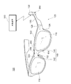
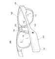
図1は、実施例におけるメガネ100の前方からの一例を示す斜視図である。図2は、実施例におけるメガネ100の後方からの一例を示す斜視図である。メガネ100は、レンズ110及びフレーム120を備える。メガネ100及びフレーム120は、アイウエアの一例である。
[Example]
FIG. 1 is a perspective view illustrating an example from the front of the
フレーム120は、一対のレンズ110を支持する。フレーム120は、リム122と、眉間部(例えばブリッジ)124と、ヨロイ126と、丁番128と、テンプル130と、モダン132と、一対のノーズパッド140と、第1電極152と、第2電極154と、第3電極156と、電線(不図示)と、処理装置200と、増幅部250とを有する。なお、メガネ100の種類によっては、一枚レンズを用いることでフレームのブリッジ部分がない場合がある。この場合、一枚レンズの眉間部分を眉間部とする。
The
一対のノーズパッド140は、右ノーズパッド142及び左ノーズパッド144を含む。リム122、ヨロイ126、丁番128、テンプル130、及びモダン132は、それぞれ左右一対に設けられる。
The pair of
リム122は、レンズ110を保持する。ヨロイ126は、リム122の外側に設けられ、丁番128によりテンプル130を回転可能に保持する。テンプル130は、使用者の耳の上部を押圧して、この部位を挟持する。モダン132は、テンプル130の先端に設けられる。モダン132は、使用者の耳の上部に接触する。なお、モダン132は、必ずしもメガネ100に設ける必要はない。
The
第1電極152及び第2電極154は、一対のノーズパッド140のそれぞれの表面に設けられ、眼電位を検出する。例えば、第1電極152は、右ノーズパッド142に設けられ、第2電極154は、左ノーズパッド144に設けられる。
The
第1電極152は、使用者の右眼の眼電位を検出する。第2電極154は、使用者の左眼の眼電位を検出する。このように、眼電位を検出するための電極を、使用者の皮膚に必然的に接触するノーズパッドの表面に設ける。これにより、使用者の眼の周囲に二対の電極を接触させるのに比べて、使用者の皮膚に与える負担を軽減することができる。
The
第3電極156は、眉間部124の表面に設けられ、眼電位を検出する。接地電極(不図示)は、モダン132の表面に設けられるとする。メガネ100にモダン132がない場合は、接地電極は、テンプル130の先に設けられる。実施例において、第1電極152、第2電極154及び第3電極156が検出する電位は、接地電極が検出する電位を基準としてもよい。
The
処理装置200は、例えば、テンプル130に設けてもよい。これにより、メガネ100を正面から見たときのデザイン性を損なうことがない。処理装置200の設置位置は、必ずしもテンプル130である必要はないが、メガネ100を装着した際のバランスを考慮して位置決めすればよい。処理装置200は、電線を介して増幅部250に接続される。なお、処理装置200と、増幅部250とは、無線を介して接続されてもよい。
The
増幅部250は、第1電極152、第2電極154及び第3電極156の近傍に設けられ、増幅対象の各電極と電線を介して接続される。増幅部250は、各電極が検出した眼電位を示す眼電図信号を取得する。例えば、増幅部250は、第1電極152、第2電極154及び第3電極156により検出された眼電位を示す眼電図信号を増幅する。
The amplifying
また、増幅部250は、眼電図信号を処理する処理部を有していれば、増幅する前又は増幅した後の各眼電図信号に対し、加減処理を行ってもよい。例えば、増幅部250は、第3電極156を基準とした第1電極152の電位を示す基準眼電図信号を求めてもよい。また、増幅部250は、第3電極156を基準とした第2電極154の電位を示す基準眼電図信号を求めてもよい。増幅部250により増幅又は処理された信号は、処理装置200に出力される。
In addition, if the
外部装置300は、通信機能を有する情報処理装置である。例えば、外部装置300は、使用者が所持する携帯電話及びスマートフォン等の携帯通信端末等である。外部装置300は、送信部220から受信した眼電図信号に基づく処理を実行する。例えば、外部装置300は、受信した眼電図信号から、瞬目や視線移動を検出する。瞬目を検出する場合の応答として、外部装置300は、使用者の瞬目の回数が増加していることを検出した場合などに、居眠りを防止するための警告を発する。外部装置300の詳細については後述する。
The
<処理装置の構成>
図3は、実施例における処理装置200の一例を示すブロック図である。図3に示すように、処理装置200は、処理部210、送信部220、電源部230、及びモーションセンサ240を有する。第1電極152、第2電極154、第3電極156は、例えば増幅部250を介して処理部210に接続される。
<Configuration of processing device>
FIG. 3 is a block diagram illustrating an example of the
処理部210は、増幅部250から増幅された眼電図信号を取得し、処理する。例えば、処理部210は、第3電極156を基準とした第1電極152の電位を示す基準眼電図信号を処理してもよい。なお、基準眼電図信号は、説明の便宜上「基準」を付したが、眼電図信号に含まれる。また、処理部210は、第3電極156を基準とした第2電極154の電位を示す基準眼電図信号を処理してもよい。
The
このとき、処理部210は、右眼及び左眼において、各電極から検出された眼電位に基づいて、眼の垂直方向及び/又は水平方向の動きを示す眼電図信号となるように処理を行ってもよい。
At this time, the
他にも、処理部210は、取得した眼電図信号がデジタル化されていなければ、デジタル化処理を行ったり、各電極から増幅された眼電図信号を取得した場合には、眼電図信号の加減処理を行ったりする。また、処理部210は、増幅部250から取得した眼電図信号をそのまま送信部220に送信してもよい。
In addition, if the acquired electrooculogram signal is not digitized, the
送信部220は、処理部210によって処理された眼電図信号を外部装置300に送信する。例えば、送信部220は、Bluetooth(登録商標)及び無線LAN等の無線通信、又は有線通信によって眼電図信号を外部装置300に送信する。電源部230は、処理部210、送信部220、モーションセンサ240及び増幅部250に電力を供給する。
The
モーションセンサ240は、メガネ100を装着した使用者の動きを検出するセンサである。モーションセンサ240は、例えば、3軸加速度センサ及び/又は3軸角速度センサであり、好ましくは、加速度及び角速度が検知可能な6軸センサである。モーションセンサ240により検出された信号(以下、センサ信号ともいう。)は、送信部220に出力され、送信部220によって、外部装置300に送信される。なお、モーションセンサ240は、外部装置300と通信可能であれば、メガネ100とは別体に設けられてもよい。
The
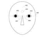
図4は、使用者に対する電極の接触位置を概略的に示す図である。第1接触位置452は、第1電極152の接触位置を表す。第2接触位置454は、第2電極154の接触位置を表す。第3接触位置456は、第3電極156の接触位置を表す。水平中心線460は、右眼402の中心と左眼404の中心とを結んだ水平方向の中心線を表す。垂直中心線462は、右眼402と左眼404との中心において水平中心線460と直交する中心線を表す。
FIG. 4 is a diagram schematically showing the contact position of the electrode with respect to the user. The
第1接触位置452及び第2接触位置454は、水平中心線460よりも下側に位置することが望ましい。また、第1接触位置452及び第2接触位置454は、第1接触位置452と第2接触位置454との中心を結ぶ線分が、水平中心線460と平行になるべく配置されることが望ましい。
It is desirable that the
また、第1接触位置452及び第2接触位置454は、第1接触位置452から右眼402への距離と、第2接触位置454と左眼404との距離が等しくなるべく配置されることが望ましい。また、第1接触位置452及び第2接触位置454は、互いに一定の距離以上離間していることが望ましい。
Further, the
第3接触位置456は、垂直中心線462上に位置することが望ましい。また、第3接触位置456は、水平中心線460よりも上側であって、第1接触位置452及び第2接触位置454から離れた位置であることが望ましい。また、例えば、第3接触位置456と右眼402との距離は、右眼402と第1接触位置452との距離よりも離間させ、左眼404との距離は、左眼404と第2接触位置454との距離よりも離間させてよい。
The
眼球は、角膜側が正に帯電しており、網膜側が負に帯電している。したがって、視線が上に移動した場合、第3電極156を基準とした第1電極152の電位及び第3電極156を基準とした第2電極154の電位が負となる。視線が下に移動した場合、第3電極156を基準とした第1電極152の電位及び第3電極156を基準とした第2電極154の電位が正となる。
The eyeball is positively charged on the corneal side and negatively charged on the retinal side. Therefore, when the line of sight moves upward, the potential of the
視線が右に移動した場合、第3電極156を基準とした第1電極152の電位が負となり、第3電極156を基準とした第2電極154の電位が正となる。視線が左に移動した場合、第3電極156を基準とした第1電極152の電位が正となり、第3電極156を基準とした第2電極154の電位が負となる。
When the line of sight moves to the right, the potential of the
第3電極156を基準とした第1電極152の電位及び第3電極156を基準とした第2電極154の電位を検出することによって、好適にノイズの影響を軽減することができる。第3接触位置456を第1接触位置452及び第2接触位置454から可能な限り離間させるべく、眉間部124は、リム122の上端又はその近傍に配置されてもよい。また、眉間部124の中心よりも上側に第3電極156は設けられてもよい。この場合、第3電極156の配置位置として、縦幅の広い眉間部124を採用することが望ましい。
By detecting the potential of the
なお、処理部210は、第3電極156を基準とした第1電極152の電位を検出する代わりに、基準電極を基準とした第1電極152の電位から、基準電極を基準とした第3電極156の電位を減じてもよい。そして同様に、処理部210は、第3電極156を基準とした第2電極154の電位を検出する代わりに、基準電極を基準とした第2電極154の電位から、基準電極を基準とした第3電極156の電位を減じてもよい。
Instead of detecting the potential of the
基準電極としては、接地電極を用いてもよい。また、メガネ100の、第1電極152、第2電極154及び第3電極156から離間した位置に、別途基準電極を設けてもよい。例えば、基準電極は、右側のモダン132に設けられてもよい。また、基準電極は、右側のテンプル130の使用者の肌に接する部位に設けられてもよい。
A ground electrode may be used as the reference electrode. Further, a reference electrode may be separately provided in the
なお、基準電極を基準とした第1電極152の電位から第3電極156の電位を減じる処理、及び基準電極を基準とした第2電極154の電位から第3電極156の電位を減じる処理は、処理部210が実行してもよく、増幅部250又は外部装置300が実行してもよい。この場合、処理対象の電位を示す信号は、増幅部250により増幅されている。
The process of subtracting the potential of the
<増幅部の構成>
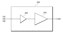
次に、増幅部250の構成について説明する。図5は、実施例における増幅部250の構成の一例を示す図である。図5に示すように、増幅部250は、第1アンプ260及び第2アンプ270を有する。第1アンプ260は、第2アンプ270の前段に位置し、バッファアンプとして機能するアンプである。以下、第1アンプ260をバッファアンプ260とも称する。第2アンプ270は、メインのアンプとして機能するアンプである。以下、第2アンプ270は、メインアンプ270とも称する。メインアンプ270により増幅された信号は処理装置200に有線又は無線を用いて出力される。
<Configuration of amplification unit>
Next, the configuration of the
増幅部250の設置位置は、眉間部124部分であることが望ましい。なお、増幅部250は、眉間部124に埋め込むようにして設けてもよい。前述したとおり、各電極は可能な限り離間させた方が望ましいが、各電極の設置位置はフレーム120の形状に依存してしまうため、離間させるにしても限界がある。
As for the installation position of the
このため、各電極の電位差が十分な大きさにならない場合があり、各電極で検出された小さい電位を示す眼電図信号にノイズが混入してしまうと、十分な精度の電位を検出することが困難になってしまう。 For this reason, the potential difference between the electrodes may not be sufficiently large, and if noise is mixed in an electrooculogram signal indicating a small potential detected at each electrode, a sufficiently accurate potential can be detected. Will become difficult.
そこで、実施例においては、検出された眼電図信号にノイズが混入する前に増幅することを目的として、増幅部250は、第1電極152、第2電極154及び第3電極156の近傍に設けられる。例えば、増幅部250は、各電極に近く、比較的フレーム120にスペースが存在する眉間部124部分に設けることが好ましい。これにより、各電極により検出された眼電図信号が電線を通過する間に、ノイズが混入して眼電図信号の精度を低下させるリスクを減らすことができる。
Therefore, in the embodiment, the amplifying
次に、メインアンプ270の前段の位置にバッファアンプ260を設ける理由を、図6を用いて説明する。図6は、バッファアンプ260を設ける理由を説明するための図である。図6に示す例は、第3電極156を用いるが、第1電極152及び第2電極154においても同様である。
Next, the reason why the
第3電極156は、メガネ100を装着した際、人肌に触れるため、グランドとの間に抵抗R0が存在すると考えてよい。このとき、抵抗R0は、例えば数100kΩである。また、メインアンプ270には、内部抵抗R1が存在する。このとき、メインアンプ270として通常のアンプを用いると、内部抵抗R1は、数10kΩ〜数100kΩである。
Since the
ここで、理想的にはメインアンプ270に電流が流れ込まないことであるが、内部抵抗R1が抵抗R0よりも小さいと、電流がメインアンプ270側に流れ込む。そうすると、電極の電圧Viとメインアンプ270の電圧Vxとが分圧されて観測されてしまう。そこで、メインアンプ270の前段の位置にバッファアンプ260を設けてメインアンプ270側に電流が流れ込まないようにする。
Here, although ideally is that does not flow a current to the
図7は、実施例における増幅部の構成の他の例を示す図である。図7に示す増幅部は、符号250Aと表記される。増幅部250Aは、バッファアンプ260、メインアンプ270、A/D変換部280、及び無線通信部290を有する。バッファアンプ260及びメインアンプ270は、図5に示す機能と同様であるため、以下では、A/D変換部280及び無線通信部290について主に説明する。
FIG. 7 is a diagram illustrating another example of the configuration of the amplifying unit in the embodiment. The amplifying unit shown in FIG. 7 is denoted by reference numeral 250A. The amplification unit 250A includes a
A/D変換部280は、メインアンプ270により増幅された信号をアナログからデジタルに変換する。A/D変換部280は、デジタル変換した信号を無線通信部290に出力する。
The A /
無線通信部290は、A/D変換部280により変換されたデジタル信号を、無線通信を用いて処理装置200に送信する。よって、無線通信部290は、送信部として機能する。無線通信部290は、例えばBluetooth(登録商標)及び無線LAN等の無線通信を用いる。また、無線通信部290は、外部装置300にデジタル信号を直接送信してもよい。
The
なお、実施例では、バッファアンプ260及びメインアンプ270を1つ設ける例を示したが、この場合は各電極からの眼電図信号に対して順番を決めて増幅していけばよい。また、各電極それぞれにバッファアンプ260及びメインアンプ270を設けてもよい。
In the embodiment, an example is shown in which one
<外部装置の構成>
次に、外部装置300の構成について説明する。図8は、実施例における外部装置300の構成の一例を示すブロック図である。図8に示すように、外部装置300は、通信部310、記憶部320、及び制御部330を有する。
<Configuration of external device>
Next, the configuration of the
通信部310は、Bluetooth(登録商標)及び無線LAN等の無線通信、又は有線通信によって眼電図信号やセンサ信号を受信する。通信部310は、処理装置200の通信部220から受信した眼電図信号やセンサ信号を制御部330に出力する。
The
制御部330は、例えばCPU(Central Processing Unit)であり、各部の制御を行ったり、各種の演算処理を行ったりする。図8に示す例では、制御部330は、取得部340、判定部342、検出部346を有する。
The
取得部340は、加速度センサ及び/又は角速度センサにより検出される、対象者の動きを示すセンサ信号、及び対象者の眼周辺に接触する各電極により検出される眼電位に基づく眼電図信号を取得する。取得部340は、例えば、通信部310が受信した眼電図信号やセンサ信号を取得すると、眼電図信号を検出部346に出力し、センサ信号を判定部342に出力する。なお、対象者の動きとは、対象者の直接的な動きでもよいし、乗り物などに乗ることによる間接的な動きでもよい。
The
制御部330は、取得された眼電図信号に対し、垂直方向及び水平方向の眼の動きを示す眼電図信号の極大値及び極小値を記憶部320に記憶するようにする。また、制御部330は、所定期間毎に、垂直方向及び水平方向の眼の動きを示す眼電図信号の最大値及び/又は最小値を記憶部320に記憶するようにしてもよい。所定期間は、例えば200msecとするが、この限りではない。また、所定期間は、時間窓を用いることで重複を許して時間的に変動するようにしてもよい。また、制御部330は、取得されたセンサ信号を記憶部320に記憶してもよい。ここでいう垂直方向とは、顔を基準とした頭の上から下までの方向をいい、水平方向とは、垂直方向に直交する方向をいう。
The
記憶部320は、例えば、RAM(Random Access Memory)であり、垂直方向及び水平方向の眼電図信号の極大値(又は所定期間毎の最大値)及び/又は極小値(又は所定期間毎の最小値)を記憶する。例えば、記憶部320は、極大値用のFIFOバッファと、極小値用のFIFOバッファとを有する。FIFOバッファは、極大値または極小値のデータにより記憶容量が一杯になったときは、最も古いデータが消去されて最新のデータが記憶されることにより、記憶領域に記憶されるデータが更新される。また、記憶部320は、センサ信号を記憶してもよい。
The
また、記憶部320は、後述する瞬目検出処理や視線移動検出処理をコンピュータに実行させるプログラムを記憶する。このプログラムは、インターネット、又はSDカードなどの記録媒体を介して外部装置300にインストールされてもよいし、プリインストールされていてもよい。また、このプログラムを記憶する記憶部は、記憶部320とは別であってもよい。
In addition, the
判定部342は、取得部340から取得したセンサ信号に基づいて、メガネ100を着用した使用者(ユーザ)の動作が所定動作であるか否かを判定する。所定動作とは、例えば、歩行、走行、咳、くしゃみ、頷き、頭を振るなどの瞬目や視線移動の検出が困難になる動作である。判定部342は、センサ信号に基づいて動作判定を行うために、認識部344を有する。
Based on the sensor signal acquired from the
認識部344は、パターン認識を行うことで、所定動作を認識する。例えば、認識部344は、歩行、走行、咳、くしゃみ、頷き、頭を振るなどのセンサ信号のそれぞれのパターンを学習し、記憶部320に記憶しておく。認識部344は、取得されたセンサ信号が、学習していた1つ又は複数のパターンにマッチングするかを判定する。認識部344は、マッチングしたパターンから動作を認識する。認識部344におけるパターンマッチングの技術は、公知の技術を適用することができる。
The
判定部342は、認識部344によりセンサ信号が所定パターンであると認識された場合、センサ信号に基づく使用者の動作が所定動作であると判定し、認識部344により所定パターンが識別されなかった場合、センサ信号に基づく使用者の動作が所定動作ではないと判定する。判定部342は、判定結果に基づく制御信号を検出部346に出力する。制御信号は、例えば、センサ信号が所定動作でない場合は実行信号であり、センサ信号が所定動作である場合は停止信号である。
When the
なお、判定部342は、パターン認識以外にも、センサ信号が単純に閾値を超えるか否かの判定を行ってもよい。この場合、判定部342は、閾値を超えた場合が所定動作を行っていると判定する。この閾値は、異常なセンサ信号を検出するために用いられる値であり、通常のセンサ信号の振幅よりも大きな値が設定される。
In addition to the pattern recognition, the
検出部346は、判定部342の判定結果に応じて、取得部340から取得した眼電図信号に基づく瞬目又は視線移動の検出処理を実行する、又は停止する。検出部346は、センサ信号が所定パターンである、つまり、使用者の動作が所定動作であると判定された場合、検出処理を停止する。また、検出部346は、センサ信号が所定パターンではないと判定された場合、つまり、使用者の動作が所定動作ではないと判定された場合、検出処理を行う。具体的には、検出部346は、判定部342から、制御信号である実行信号を取得したときには検出処理を行い、判定部342から、制御信号である停止信号を取得したときには検出処理を停止する。
The
これにより、使用者が、多くのノイズが混入する可能性が高い所定動作を行っているときに、瞬目又は視線移動の検出処理を停止することで、誤検出を防止することができる。また、検出処理の停止は、省電力にも寄与する。 Thereby, when the user is performing a predetermined operation with a high possibility that a lot of noise is mixed, erroneous detection can be prevented by stopping the blink or eye movement detection processing. Moreover, the stop of the detection process also contributes to power saving.
検出部346は、検出処理を停止した後に、所定パターンではないと判定されてから所定時間が経過するまで、検出処理の停止を継続してもよい。つまり、検出部346は、一旦検出処理を停止すると、検出処理が可能な状態になっても、検出処理を所定時間停止しておく。
After stopping the detection process, the
これにより、判定結果が、センサ信号が所定パターンである(肯定)からセンサ信号が所定パターンではない(否定)になった場合に、所定動作によって不安定になっている眼電図信号を用いてすぐに検出処理を行わなくてすむ。また、眼電図信号が安定するまで検出処理を停止させておくことができる。その結果、瞬目や視線移動の誤検出を防止することができる。この所定時間は、所定パターン又は所定動作に応じて変更してもよい。所定時間は、事前の実験等により、各パターンや動作に応じて、眼電図信号が安定するまでの適切な時間が設定されていればよい。 Thereby, when the sensor signal is not a predetermined pattern (negative) from the sensor signal having a predetermined pattern (positive), an electrooculogram signal that is unstable due to a predetermined operation is used. It is not necessary to perform detection processing immediately. Moreover, the detection process can be stopped until the electrooculogram signal is stabilized. As a result, it is possible to prevent erroneous detection of blinks and eye movements. The predetermined time may be changed according to a predetermined pattern or a predetermined operation. The predetermined time may be set to an appropriate time until the electrooculogram signal is stabilized according to each pattern and operation by a prior experiment or the like.
次に、使用者が歩行しているときの眼電図信号及びセンサ信号を具体例として、検出処理の停止について説明する。図9は、歩行時の眼電図信号及びセンサ信号の一例を示す図である。 Next, stop of the detection process will be described by taking an electrooculogram signal and a sensor signal when the user is walking as a specific example. FIG. 9 is a diagram illustrating an example of an electrooculogram signal and a sensor signal during walking.
図9(A)は、歩行時の垂直方向の眼の動きを示す眼電図信号S1を示す。図9に示す期間W1は、使用者が歩行している期間を示す。図9(A)に示すように、歩行時の眼電図信号S1は、振幅が大きくなっており、瞬目や視線移動を検出することができる状態ではない。この期間W1に瞬目や視線移動の検出処理を行ってしまうと、眼電図信号S1が瞬目や視線移動の判定閾値を超えることで、多くの瞬目や視線移動が検出され、誤検出が発生してしまう。なお、縦軸の眼電強度は、眼電位の強度を示す単位であり、例えば眼電図信号の計測値×1.5(V)÷2048などで表される。 FIG. 9A shows an electrooculogram signal S1 indicating the eye movement in the vertical direction during walking. A period W1 illustrated in FIG. 9 indicates a period during which the user is walking. As shown in FIG. 9A, the electrooculogram signal S1 during walking has a large amplitude and is not in a state in which blinking or eye movement can be detected. If the process of detecting blinks and eye movements is performed during this period W1, many blinks and eye movements are detected because the electrooculogram signal S1 exceeds the determination threshold for blinks and eye movements. Will occur. The electroocular intensity on the vertical axis is a unit indicating the intensity of the electrooculogram, and is represented by, for example, measured value of electrooculogram signal × 1.5 (V) ÷ 2048.
図9(B)は、歩行時の上下方向の加速度を示すセンサ信号S2を示す。期間W1において、使用者が歩行することで、上下方向の加速度を示すセンサ信号S2が大きく振れることになる。よって、このセンサ信号S2の動きのパターンを学習しておくことで、判定部342は、使用者の歩行を認識することができる。なお、図9(B)に示すグラフの縦軸の値は、加速度を表す値である。
FIG. 9B shows a sensor signal S2 indicating the vertical acceleration during walking. In the period W1, when the user walks, the sensor signal S2 indicating the vertical acceleration greatly fluctuates. Therefore, the
なお、図9に示す例では、歩行の場合を例に用いて説明したが、走行、咳、くしゃみ、頷き、頭を振るなどの動作についても、図9と同様にして、判定部342がセンサ信号のパターンを認識しておけばよい。なお、判定部342は、センサ信号について、上下方向の加速度だけではなく、角速度の信号も用いることで、認識精度を高めるようにしてもよい。
In the example shown in FIG. 9, the case of walking has been described as an example, but the operation of running, coughing, sneezing, squeezing, shaking the head, etc. is performed by the
≪視線移動検出≫
次に、視線移動の検出について説明する。検出部346は、公知の方法を用いて視線移動を検出すればよい。例えば、検出部346は、取得した眼電図信号から右眼電図と、左眼電図とに分けて、右眼電図及び左眼電図で負の電位が示された場合には視線が上を向いたことを検出する。また、検出部346は、右眼電図及び左眼電図で正の電位が示された場合には視線が下、右眼電図で負の電位が示され左眼電図で正の電位が示された場合には視線が右、右眼電図で正の電位が示され左眼電図で負の電位が示された場合には視線が左に向いたことを検出する。
≪Gaze movement detection≫
Next, detection of eye movement will be described. The
さらに、検出部346は、右眼電図が示す電位V1と左眼電図が示す電位V2とを加減算することによって、視線の検出精度を高めることができる。例えば、V1+V2が負であり、V1−V2が略ゼロの場合は、視線が上に向けられたと検出できる。V1+V2が正であり、V1−V2が略ゼロの場合は、視線が下に向けられたと判断できる。V1+V2が略ゼロであり、V1−V2が負の場合は、視線が右に向けられたと判断できる。V1+V2が略ゼロであり、V1−V2が正の場合は、視線が左に向けられたと判断できる。V1とV2とを加減算することにより、算出される正の値及び負の値が大きくなる。したがって、その分閾値を大きく設定することができるので、ノイズを誤って視線移動として検出してしまう誤検出を低減できる。
Furthermore, the
≪瞬目検出≫
つぎに、瞬目検出について説明する。検出部346は、眼電図信号を用いた公知の瞬目検出アルゴリズムを用いることができるが、本実施例では、瞬目判定に用いる閾値を可変にするアルゴリズムについて説明する。検出部346は、閾値算出部350を有する。
≪Blink detection≫
Next, blink detection will be described. The
閾値算出部350は、記憶部320に記憶された極大値及び/又は極小値を用いて閾値を算出する。閾値算出部350は、例えば処理を簡略化するため、極大値又は極小値の絶対値の平均値等から閾値の絶対値を算出してもよい。
The
また、閾値算出部350は、記憶部320に記憶された極大値を用いて第1閾値を算出し、また、記憶部320に記憶された極小値を用いて第2閾値を算出してもよい。ここで、第1閾値は、眼が垂直方向の上に動いたことを判定するために用いられ、第2閾値は、眼が垂直方向の下に動いたことを判定するために用いられる。これにより、上方向の眼の動き、下方向の眼の動きそれぞれに閾値を設定できるので、適切な閾値判定を行うことができる。
Further, the threshold
また、閾値算出部350は、第1算出部352及び第2算出部354を有する。第1算出部352は、極大値用のFIFOバッファに記憶されている極大値の平均値及び標準偏差を算出する。また、第1算出部352は、極小値用のFIFOバッファに記憶されている最小値の平均値及び標準偏差を算出する。
The
第2算出部354は、極大値の平均値及び標準偏差に基づいて第1閾値を算出し、極小値の平均値及び標準偏差に基づいて第2閾値を算出する。これにより、例えば対象者の直近の状態を示す眼電図信号を用いて閾値を設定することができる。また、第1閾値及び第2閾値は、使用者の直近の状態を示す信号の強度に追従して値を変更させることができる。
The
例えば、第2算出部354は、極大値の平均値に、極大値の標準偏差に係数を乗算した値を加算した値を第1閾値とする。第2算出部354は、極小値の平均値から、極小値の標準偏差に係数を乗算した値を減算した値を第2閾値とする。これにより、適切な閾値を設定することができる。
For example, the
また、閾値算出部350は、記憶部320に極大値及び/又は極小値が記憶される度に、第1閾値及び第2閾値を更新する。これにより、閾値算出部350は、過去の眼電図信号に基づいて閾値を設定することができるため、眠くなって眼の動きが遅くなり、眼電図信号が弱くなった場合であっても、その弱くなった信号に応じて閾値を設定することができるので、適切に瞬目を検出することができる。
Further, the threshold
また、閾値算出部350は、記憶部320に記憶された所定個の極大値の平均を第1閾値としたり、記憶部320に記憶された所定個の極小値の平均を第2閾値としたりしてもよい。また、閾値算出部350は、記憶部320に記憶された極大値及び極小値それぞれの標準偏差を用いて第1閾値及び第2閾値を算出してもよい。
Further, the
検出部346は、第2算出部354により算出された第1閾値、及び第2閾値を用いて、眼の垂直方向の動きを示す眼電図信号から瞬目を検出する。例えば、検出部346は、第1閾値以上となる記憶部320に記憶された極大値の第1時刻と、第2閾値以下となる記憶部320に記憶された極小値の第2時刻との差分が所定時間以内であれば、瞬目を検出する。ここで、第2時刻は、第1時刻以降であって直近の時刻とする。所定時間は、例えば500msecとするがこの限りではない。
The
なお、検出部346は、右眼、左眼それぞれの眼電図信号を用いて瞬目を検出し、所定範囲内のタイミングで両目において瞬目が検出されたときに最終的な瞬目を検出してもよい。また、検出部346は、右眼と左眼は同様の動きをすることを前提とし、双方の眼電図信号の平均を用いて瞬目を検出してもよい。次に、具体的な眼電図信号を用いて瞬目検出アルゴリズムについて説明する。
Note that the
図10は、眼の垂直方向の動きを示す眼電図信号の一例を示す図である。図10に示す眼電図信号S3は、片側の眼の垂直方向の動きを示す眼電図信号である。ここで、図10を用いて瞬目検出アルゴリズムを説明する。以下に説明する瞬目検出アルゴリズムは、所定期間の最大値及び最小値を用いて閾値を算出する場合のアルゴリズムである。 FIG. 10 is a diagram illustrating an example of an electrooculogram signal indicating the vertical movement of the eye. The electrooculogram signal S3 shown in FIG. 10 is an electrooculogram signal indicating the vertical movement of one eye. Here, the blink detection algorithm will be described with reference to FIG. The blink detection algorithm described below is an algorithm for calculating a threshold value using the maximum value and the minimum value of a predetermined period.
(1)所定期間ごとの最大値、最小値を求める
制御部330は、眼電図信号S3の所定期間T1(例えば500msec)ごとの最大値、最小値を求める。
(1) Obtaining maximum and minimum values for each predetermined period The
(2)最大値が極大値である場合、第1FIFOバッファに保存する
制御部330は、(1)で求めた最大値が極大値である場合、第1FIFOバッファ(記憶部320)に保存する。
(2) When the maximum value is a maximum value, it is stored in the first FIFO buffer. When the maximum value obtained in (1) is a maximum value, the
(3)最小値が極小値である場合、第2FIFOバッファに保存する
制御部330は、(1)で求めた最小値が極小値である場合、第1FIFOバッファとは別領域の第2FIFOバッファに保存(記憶部320)する。なお、(2)及び(3)について、順序は問わない。以降、第1FIFOバッファ及び第2FIFOバッファをまとめる場合は、単にバッファと称する。図10において、眼電図信号S3上にある黒点は、各期間において極大値又は極小値として検出された値を表す。なお、極大値及び極小値は、微分を用いて、例えば眼電図信号S3の差分信号を用いて求めることができる。
(3) When the minimum value is a minimum value, the
(4)バッファの容量分データが保存されたら、平均値及び標準偏差を算出する
第1算出部352は、第1FIFOバッファに保存されている最大値の平均値(a1)及び標準偏差(b1)を算出する。また、第1算出部352は、第2FIFOバッファに保存されている最大値の平均値(a2)及び標準偏差(b2)を算出する。
(4) When the buffer capacity data is stored, the average value and the standard deviation are calculated. The
(5)閾値を算出する
第2算出部354は、(4)で算出された平均値及び標準偏差を用いて第1閾値及び第2閾値を算出する。第1閾値(Th1)及び第2閾値(Th2)は、以下の式で算出される。
Th1=a1+E×b1・・・式(1)
Th2=a2−E×b2・・・式(2)
ここで、係数Eは、例えば2とする。
なお、第1閾値(Th1)、第2閾値(Th2)の絶対値に下限値を設定しておいてもよい。これにより、眼のわずかな上下運動を瞬きであると誤検出することを防止することができる。また、係数Eは、信号強度に応じて可変に設定できるようにされてもよい。
(5) Calculating the threshold The
Th1 = a1 + E × b1 Formula (1)
Th2 = a2-E × b2 Formula (2)
Here, the coefficient E is set to 2, for example.
In addition, you may set a lower limit to the absolute value of a 1st threshold value (Th1) and a 2nd threshold value (Th2). As a result, it is possible to prevent erroneous detection of a slight vertical movement of the eye as blinking. Further, the coefficient E may be variably set according to the signal strength.
図10において、第1閾値の例として、符号TH1で表し、第2閾値の例として符号TH2で表す。図10に示すとおり、眼電図信号の時間経過に伴って、それぞれの閾値が変動し、さらに、眼電図信号の強さ(振幅の大きさ)に追従して閾値が適切に変更される。図8に示す第1閾値TH1と第2閾値TH2は、閾値の変動を概念的に示したものに過ぎない。 In FIG. 10, the example of the first threshold is represented by the symbol TH1, and the example of the second threshold is represented by the symbol TH2. As shown in FIG. 10, each threshold value varies with the passage of time of the electrooculogram signal, and further, the threshold value is appropriately changed following the intensity (magnitude) of the electrooculogram signal. . The first threshold value TH1 and the second threshold value TH2 shown in FIG. 8 are merely conceptually showing threshold value fluctuations.
(6)第1閾値以上の最大値、及び第2閾値以下の最小値を特定する
検出部342は、(5)で算出された第1閾値以上の最大値を特定する。ここで、閾値判定の対象となる最大値は、第1FIFOバッファに記憶されており、閾値判定がまだされていない最大値である。
(6) Identify the maximum value greater than or equal to the first threshold and the minimum value less than or equal to the second threshold The
また、検出部342は、(5)で算出された第2閾値以下の最小値を特定する。ここで、閾値判定の対象となる最小値は、第2FIFOバッファに記憶されており、閾値判定がまだされていない最小値である。図10において、特定された最大値及び最小値は、四角で囲われた黒点により表される。
In addition, the
(7)瞬目を検出する
検出部342は、特定された最大値毎に、この最大値の第1時刻と、特定された最小値の第2時刻であり、この第1時刻以降の直近の第2時刻との差が、所定時間以内であれば、その眼の上下の動きを瞬目とみなして検出する。
(7) Detecting blinks The
図10において、例えば、特定された最大値の時刻t11と、t11以降で直近に特定された最小値の時刻t21との差が所定時間以内であれば、その眼の動きを瞬目として検出する。所定時間は、例えば500msecとする。 In FIG. 10, for example, if the difference between the specified maximum value time t11 and the minimum value time t21 specified most recently after t11 is within a predetermined time, the eye movement is detected as a blink. . The predetermined time is, for example, 500 msec.
以上、瞬目検出アルゴリズムを説明したが、このアルゴリズムは、あくまでも一例であり、この例に限らない。なお、瞬目、視線移動の検出処理においては、眼電図信号の時間方向の差分信号を用いて上述した処理と同様の処理を行ってもよい。差分信号とは、例えば時間tの眼電図信号から時間tの所定時間前の眼電図信号を減算した信号である。これにより、ノイズ耐性が強い差分信号を用いることで、検出精度を向上させることができる。 The blink detection algorithm has been described above, but this algorithm is merely an example, and the present invention is not limited to this example. In the blink and eye movement detection processing, the same processing as described above may be performed using the difference signal in the time direction of the electrooculogram signal. The difference signal is, for example, a signal obtained by subtracting an electrooculogram signal a predetermined time before time t from an electrooculogram signal at time t. Thereby, detection accuracy can be improved by using a difference signal with strong noise tolerance.
<動作>
次に、実施例における外部装置300の動作について説明する。図11は、実施例における瞬目、視線移動の検出処理に関する処理の一例を示すフローチャートである。図11に示すフローチャートは、使用者がメガネ100を装着して、第1電極152、第2電極154、第3電極156及び接地電極が使用者の皮膚に接触した状態であって、外部装置300が瞬目又は視線移動の検出を実行するモードである動作モードに設定された場合に開始する。
<Operation>
Next, the operation of the
図11に示すステップS102で、取得部340は、メガネ100から、眼電図信号及びセンサ信号を取得する。
In step S <b> 102 illustrated in FIG. 11, the
ステップS104で、判定部342は、センサ信号が所定パターンであるか否かを判定する。例えば、判定部342は、認識部344によるパターン認識を用いて判定処理を行う。センサ信号が所定パターンであると判定されれば(ステップS104−YES)、瞬目又は視線移動の検出処理を停止するため、判定部342は、検出部346に停止信号を出力し、処理はステップS102に戻る。センサ信号が所定パターンではないと判定されれば(ステップS104−NO)、判定部342は、検出部346に実行信号を出力し、処理はステップS106に進む。
In step S104, the
ステップS106で、検出部346は、判定部342から実行信号を取得した場合は、瞬目又は視線移動の検出処理を行う。すなわち、検出部346は、判定部342から停止信号を取得しない限り、検出処理を行う。
In step S <b> 106, when the
なお、一旦検出処理が停止され、再開されるときのタイミングは、検出部346が実行信号を取得したときなどである。なお、検出部346は、検出処理の停止後に、実行信号を取得したり、停止信号を取得しなくなったりしても、所定時間、検出処理の停止を継続してもよい。
Note that the timing when the detection process is once stopped and restarted is when the
以上の処理により、瞬目又は視線移動の誤検出が発生しやすい使用者の動作を判定することができ、この動作が行われている場合には、検出処理を停止して誤検出が行われないようにすることができる。 Through the above processing, it is possible to determine the user's motion that is likely to cause erroneous detection of blinking or eye movement. When this operation is performed, the detection processing is stopped and erroneous detection is performed. Can not be.
次に、図12は、実施例における瞬目検出処理の一例を示すフローチャートである。以下に説明する瞬目検出処理は、極大値及び極小値の移動平均を用いて判定閾値を算出する。 Next, FIG. 12 is a flowchart illustrating an example of blink detection processing in the embodiment. In the blink detection process described below, a determination threshold is calculated using a moving average of the maximum value and the minimum value.
ステップS202で、制御部330は、算出される極大値及び/又は極小値を記憶部320に記憶する。
In step S <b> 202, the
ステップS204で、閾値算出部350は、記憶部320に記憶された極大値及び/又は最小値を用いて閾値(第1閾値及び第2閾値)を算出する。このとき、閾値算出部350は、例えば直近の10個の極大値の平均値を第1閾値、又は直近の10個の極小値の平均値を第2閾値とする。なお、後に瞬目と判定される極大値及び極小値は、次回以降の平均算出処理から除外してもよい。
In step S <b> 204, the threshold
ステップS206で、検出部346は、第1閾値以上となる極大値の第1時刻、又は第2閾値以下となる極小値の第2時刻を特定する。このとき、検出部360は、第2時刻として、特定した第1時刻以降の直近の極小値の時刻を特定する。
In step S206, the
ステップS208で、検出部346は、第2時刻−第1時刻が所定時間より小さいかを判定する。この条件が満たされれば(ステップS208−YES)ステップS210に進み、この条件が満たされなければ(ステップS208−NO)ステップS202に戻る。
In step S208, the
ステップS210で、検出部346は、第1時刻と第2時刻との間の眼の動きを瞬目として検出する。
In step S210, the
以上の処理により、外部装置300は、適切な閾値を用いて、瞬目を検出することができる。
Through the above processing, the
以上、実施例によれば、モーションセンサ240からのセンサ信号を用いて、眼電図信号が大きく振れる動作を使用者が行っているかを判定し、使用者がこの動作を行っているときには、瞬目や視線移動の検出処理を停止することで、誤検出を防止することができる。
As described above, according to the embodiment, the sensor signal from the
なお、本実施例において、アイウエアがメガネである場合について説明した。しかし、アイウエアはこれに限定されない。アイウエアは、眼に関連する装具であればよく、メガネ、サングラス、ゴーグル及びヘッドマウントディスプレイならびにこれらのフレームなどの顔面装着具又は頭部装着具であってよい。 In the present embodiment, the case where the eyewear is glasses has been described. However, eyewear is not limited to this. The eyewear may be any device related to the eye, and may be a face wearing device or a head wearing device such as glasses, sunglasses, goggles and a head mounted display and their frames.
本実施例において、メガネ100が第3電極156を備える例を挙げて説明した。しかし、メガネ100はこれに限定されない。メガネ100が、第3電極156を備えなくてもよい。この場合、基準電極を基準とした第1電極152の電位が示す眼電図及び基準電極を基準とした第2電極154の電位が示す眼電図が、外部装置300に送信されればよい。ここで、接地電極を第3電極156の位置に設けて、基準電極としてもよい。また、左モダンに設けられた接地電極を基準電極として用いてもよいし、第1電極152及び第2電極154から離間した位置に、別途設けられた電極を基準電極として用いてもよい。
In this embodiment, the example in which the
本実施例において、メガネ100が、リム122と一体になっているノーズパッド140を備える例を挙げて説明した。しかし、メガネ100はこれに限定されない。メガネ100が、リム122に備え付けられたクリングスと、クリングスに取り付けられたノーズパッド140とを備えてもよい。この場合、ノーズパッド140の表面に設けられた電極は、クリングスを介して、フレームに埋設された電線と電気的に接続される。
In the present embodiment, the example in which the
本実施例において、第1電極152及び第2電極154をノーズパッド140の中心よりも下側に設ける例を挙げて説明した。しかし、これに限定されない。ノーズパッド140が下側に延伸する延伸部を備え、第1電極152及び第2電極154を延伸部に設けてもよい。これにより、眼及び鼻の位置の個人差によってノーズパッドが眼の真横に位置してしまう使用者であっても、第1電極152及び第2電極154を眼の位置よりも下に接触させることができる。
In the present embodiment, the
本実施例において、第3電極156を眉間部124の表面に設ける例を挙げて説明した。しかし、これに限定されない。眉間部124が、上側に延伸する延伸部を備え、延伸部に第3電極156を設けてもよい。またさらに、延伸部と眉間部124との間に延伸部を上下に可動させる可動部を備え、第3電極156の位置を上下に調整可能としてもよい。これにより、眼の位置の個人差によって、第3電極156の接触位置が眼の近傍になってしまう使用者であっても、調整により第3電極156の接触位置を眼から離間させることができる。また、本実施例において、各電極の位置は前述した位置に限られず、眼の垂直方向及び水平方向の動きを示す眼電図信号が取得できる位置に配置されていればよい。
In the present embodiment, the example in which the
本実施例では、外部装置300の例として、処理装置200と別体の、携帯電話及びスマートフォン等の携帯通信端末を挙げて説明した。しかし、これに限定されない。外部装置300を、処理装置200と一体のユニットとしてもよい。この場合、外部装置300は、アイウエアに一体として設けられる。
In the present embodiment, as an example of the
また、本実施例では、電線としてシールドケーブルを用いることで、ノイズの混入を防ぐようにしてもよい。 In the present embodiment, a shield cable may be used as the electric wire to prevent noise from being mixed.
また、本実施例では、図1において3つの電極を用いる構成を例示したが、4つ以上の電極を用いる構成であってもよい。この場合、メガネは、上部電極と、下部電極と、左部電極と、右部電極とを有する。例えば、上部電極及び下部電極は、図1に示すリム122に設けられ、左部電極は、左テンプル130に設けられ、右部電極は、右テンプル130に設けられるが、必ずしもこの位置にある必要はない。なお、これらの電極は、顔の一部に接触しているとする。
Further, in this embodiment, the configuration using three electrodes is illustrated in FIG. 1, but a configuration using four or more electrodes may be used. In this case, the glasses have an upper electrode, a lower electrode, a left electrode, and a right electrode. For example, the upper electrode and the lower electrode are provided on the
4つの電極の例では、上部電極及び下部電極の電圧差により、眼の上下方向を検知することができ、左部電極及び右部電極の電圧差により、眼の左右方向を検知することができる。 In the example of four electrodes, the vertical direction of the eye can be detected by the voltage difference between the upper electrode and the lower electrode, and the horizontal direction of the eye can be detected by the voltage difference between the left electrode and the right electrode. .
以上、本発明について実施例を用いて説明したが、本発明の技術的範囲は上記実施例に記載の範囲には限定されない。上記実施例に、多様な変更又は改良を加えることが可能であることが当業者に明らかである。その様な変更又は改良を加えた形態も本発明の技術的範囲に含まれ得ることが、特許請求の範囲の記載から明らかである。 As mentioned above, although this invention was demonstrated using the Example, the technical scope of this invention is not limited to the range as described in the said Example. It will be apparent to those skilled in the art that various modifications or improvements can be made to the above-described embodiments. It is apparent from the description of the scope of claims that embodiments with such changes or improvements can be included in the technical scope of the present invention.
100 メガネ
120 フレーム
124 眉間部
140 ノーズパッド
152 第1電極
154 第2電極
156 第3電極
200 処理装置
300 外部装置
320 記憶部
330 制御部
340 取得部
342 判定部
344 認識部
346 検出部
350 閾値算出部
100
Claims (6)
前記眼電図信号に基づいて、瞬目又は視線移動の検出処理を行う検出ステップと、
前記センサ信号が所定パターンであるか否かを判定する判定ステップと、
前記センサ信号が前記所定パターンであると判定された場合、前記検出処理を停止する停止ステップと、
をコンピュータに実行させるプログラム。 An acquisition step of acquiring a sensor signal indicating the movement of the subject detected by the acceleration sensor and / or the angular velocity sensor, and an electrooculogram signal based on an electrooculogram detected by each electrode in contact with the periphery of the eye of the subject. When,
Based on the electrooculogram signal, a detection step of performing detection processing of blink or eye movement;
A determination step of determining whether the sensor signal is a predetermined pattern;
A stop step of stopping the detection process when the sensor signal is determined to be the predetermined pattern;
A program that causes a computer to execute.
前記検出処理を停止した後に、前記所定パターンではないと判定されてから所定時間が経過するまで、前記検出処理の停止を継続する、請求項1に記載のプログラム。 The stopping step includes
The program according to claim 1, wherein after the detection process is stopped, the detection process is stopped until a predetermined time elapses after it is determined that the pattern is not the predetermined pattern.
前記加速度センサ、前記角速度センサ、及び前記各電極が設けられたアイウエアから前記センサ信号及び前記眼電図信号を取得する、請求項1乃至3いずれか一項に記載のプログラム。 The obtaining step includes
The program according to any one of claims 1 to 3, wherein the sensor signal and the electrooculogram signal are acquired from eyewear provided with the acceleration sensor, the angular velocity sensor, and the electrodes.
前記センサ信号が1又は複数の所定パターンであるか否かを判定する判定部と、
前記所定パターンでないと判定された場合、前記眼電図信号に基づく瞬目又は視線移動の検出処理を行い、前記所定パターンであると判定された場合、前記検出処理を停止する検出部と、
を備える情報処理装置。 An acquisition unit that acquires a sensor signal indicating the movement of a subject detected by an acceleration sensor and / or an angular velocity sensor, and an electrooculogram signal based on an electrooculogram detected by each electrode that contacts the periphery of the subject's eyes. When,
A determination unit for determining whether the sensor signal is one or a plurality of predetermined patterns;
When it is determined that the pattern is not the predetermined pattern, a detection process for performing blink or eye movement based on the electrooculogram signal, and when the pattern is determined to be the predetermined pattern, a detection unit that stops the detection process;
An information processing apparatus comprising:
一対のノーズパッドを有するフレームと、
前記一対のノーズパッドそれぞれの表面に設けられる第1電極及び第2電極と、
前記眉間部の表面に設けられる第3電極と、
加速度センサ及び/又は角速度センサと、
前記加速度センサ及び/又は前記角速度センサにより検出されるセンサ信号、及び各電極により検出される眼電位に基づく眼電図信号を取得する取得部と、
前記センサ信号が1又は複数の所定パターンであるか否かを判定する判定部と、
前記所定パターンでないと判定された場合、前記眼電図信号に基づく瞬目又は視線移動の検出処理を行い、前記所定パターンであると判定された場合、前記検出処理を停止する検出部と、
備えるアイウエア。 Between the eyebrows,
A frame having a pair of nose pads;
A first electrode and a second electrode provided on the surface of each of the pair of nose pads;
A third electrode provided on the surface of the portion between the eyebrows;
An acceleration sensor and / or an angular velocity sensor;
An acquisition unit for acquiring an electrooculogram signal based on the sensor signal detected by the acceleration sensor and / or the angular velocity sensor and the electrooculogram detected by each electrode;
A determination unit for determining whether the sensor signal is one or a plurality of predetermined patterns;
When it is determined that the pattern is not the predetermined pattern, a detection process for performing blink or eye movement based on the electrooculogram signal, and when the pattern is determined to be the predetermined pattern, a detection unit that stops the detection process;
Eyewear to prepare.
Priority Applications (2)
| Application Number | Priority Date | Filing Date | Title |
|---|---|---|---|
| JP2014225520A JP2017227941A (en) | 2014-11-05 | 2014-11-05 | Program, information processing device, and eyewear |
| PCT/JP2015/080940 WO2016072395A1 (en) | 2014-11-05 | 2015-11-02 | Program, information processing device, and eyewear |
Applications Claiming Priority (1)
| Application Number | Priority Date | Filing Date | Title |
|---|---|---|---|
| JP2014225520A JP2017227941A (en) | 2014-11-05 | 2014-11-05 | Program, information processing device, and eyewear |
Publications (1)
| Publication Number | Publication Date |
|---|---|
| JP2017227941A true JP2017227941A (en) | 2017-12-28 |
Family
ID=55909120
Family Applications (1)
| Application Number | Title | Priority Date | Filing Date |
|---|---|---|---|
| JP2014225520A Pending JP2017227941A (en) | 2014-11-05 | 2014-11-05 | Program, information processing device, and eyewear |
Country Status (2)
| Country | Link |
|---|---|
| JP (1) | JP2017227941A (en) |
| WO (1) | WO2016072395A1 (en) |
Cited By (1)
| Publication number | Priority date | Publication date | Assignee | Title |
|---|---|---|---|---|
| WO2021144838A1 (en) * | 2020-01-14 | 2021-07-22 | オリンパス株式会社 | Display control device, display control method, display control program, and endoscope system |
Families Citing this family (1)
| Publication number | Priority date | Publication date | Assignee | Title |
|---|---|---|---|---|
| KR102627452B1 (en) * | 2017-04-14 | 2024-01-18 | 매직 립, 인코포레이티드 | Multi-mode eye tracking |
Family Cites Families (7)
| Publication number | Priority date | Publication date | Assignee | Title |
|---|---|---|---|---|
| JP2007166474A (en) * | 2005-12-16 | 2007-06-28 | Softbank Mobile Corp | Information communication terminal |
| JP2008117056A (en) * | 2006-11-01 | 2008-05-22 | Nec Corp | Mobile terminal with acceleration sensor, method for registering pattern of acceleration, and method and program for comparing pattern of acceleration |
| JP2011192231A (en) * | 2010-03-17 | 2011-09-29 | Aisin Aw Co Ltd | In-vehicle input device, and input program therefor |
| JP5953714B2 (en) * | 2011-11-24 | 2016-07-20 | セイコーエプソン株式会社 | Device, head-mounted display device, device control method, and head-mounted display device control method |
| JP2013240518A (en) * | 2012-05-22 | 2013-12-05 | Kyocera Corp | Electronic device |
| JP5661067B2 (en) * | 2012-05-29 | 2015-01-28 | 株式会社ジェイアイエヌ | Eyewear |
| JP5941427B2 (en) * | 2013-03-28 | 2016-06-29 | ビッグローブ株式会社 | Information processing apparatus, wearing state detection method, and program |
-
2014
- 2014-11-05 JP JP2014225520A patent/JP2017227941A/en active Pending
-
2015
- 2015-11-02 WO PCT/JP2015/080940 patent/WO2016072395A1/en active Application Filing
Cited By (1)
| Publication number | Priority date | Publication date | Assignee | Title |
|---|---|---|---|---|
| WO2021144838A1 (en) * | 2020-01-14 | 2021-07-22 | オリンパス株式会社 | Display control device, display control method, display control program, and endoscope system |
Also Published As
| Publication number | Publication date |
|---|---|
| WO2016072395A1 (en) | 2016-05-12 |
Similar Documents
| Publication | Publication Date | Title |
|---|---|---|
| CN110520824B (en) | Multimode eye tracking | |
| US9706941B2 (en) | Eyewear | |
| US20160070122A1 (en) | Computerized replacement temple for standard eyewear | |
| JP2015213734A (en) | Program, information processing device, and eyewear | |
| KR20140072524A (en) | Apparatus for measuring fatigue degree of driver's eye | |
| US20180064371A1 (en) | Posture detection apparatus, glasses-type electronic device, posture detection method, and program | |
| CN110366388B (en) | Information processing method, information processing apparatus, and computer-readable storage medium | |
| JP6656166B2 (en) | Program, information processing device, and eyewear | |
| WO2016072395A1 (en) | Program, information processing device, and eyewear | |
| JP6687639B2 (en) | Information processing method, information processing device, program, and eyewear | |
| WO2015159851A1 (en) | Detection unit, eyewear, and ocular potential detection system | |
| WO2016076268A1 (en) | Program, information processing device, and eyewear | |
| JP6594953B2 (en) | Gaze movement detection method, program, information processing apparatus, and eyewear | |
| WO2017064800A1 (en) | Program, information processing device, and eyewear | |
| CN115844427A (en) | Eye detection method and apparatus | |
| WO2016152849A1 (en) | Signal processing method, program, information processing device, and eyewear | |
| US10966651B2 (en) | Analytics and processing of biological signals from sensors | |
| WO2017064799A1 (en) | Eyewear | |
| WO2017150148A1 (en) | Eye blink detection device, eyeglass-type electronic equipment, eye blink detection method, and program | |
| JP2015205030A (en) | Eyewear | |
| JP5919323B2 (en) | Blink detector and glasses-type electronic device | |
| JP2017192548A (en) | Eyewear, information processing method, and program | |
| JP6538203B2 (en) | Electro-oculogram calibration device, eyeglass-type electronic device, electro-oculogram calibration method and program |