JP2017223496A - Battery system - Google Patents
Battery system Download PDFInfo
- Publication number
- JP2017223496A JP2017223496A JP2016117960A JP2016117960A JP2017223496A JP 2017223496 A JP2017223496 A JP 2017223496A JP 2016117960 A JP2016117960 A JP 2016117960A JP 2016117960 A JP2016117960 A JP 2016117960A JP 2017223496 A JP2017223496 A JP 2017223496A
- Authority
- JP
- Japan
- Prior art keywords
- metal hydride
- hydride battery
- value
- self
- current
- Prior art date
- Legal status (The legal status is an assumption and is not a legal conclusion. Google has not performed a legal analysis and makes no representation as to the accuracy of the status listed.)
- Granted
Links
Images


Classifications
-
- Y—GENERAL TAGGING OF NEW TECHNOLOGICAL DEVELOPMENTS; GENERAL TAGGING OF CROSS-SECTIONAL TECHNOLOGIES SPANNING OVER SEVERAL SECTIONS OF THE IPC; TECHNICAL SUBJECTS COVERED BY FORMER USPC CROSS-REFERENCE ART COLLECTIONS [XRACs] AND DIGESTS
- Y02—TECHNOLOGIES OR APPLICATIONS FOR MITIGATION OR ADAPTATION AGAINST CLIMATE CHANGE
- Y02E—REDUCTION OF GREENHOUSE GAS [GHG] EMISSIONS, RELATED TO ENERGY GENERATION, TRANSMISSION OR DISTRIBUTION
- Y02E60/00—Enabling technologies; Technologies with a potential or indirect contribution to GHG emissions mitigation
- Y02E60/10—Energy storage using batteries
Landscapes
- Tests Of Electric Status Of Batteries (AREA)
- Charge And Discharge Circuits For Batteries Or The Like (AREA)
- Secondary Cells (AREA)
Abstract
Description
この発明は、電池システムに関し、特に、ニッケル水素電池を備える電池システムにおいてニッケル水素電池の蓄電量を推定する技術に関する。 The present invention relates to a battery system, and more particularly, to a technique for estimating a storage amount of a nickel metal hydride battery in a battery system including a nickel metal hydride battery.
特開2007−333447号公報(特許文献1)は、二次電池の充電状態(State Of Charge)を示すSOC値(二次電池の満充電容量に対する蓄電量を0〜100%で表わした値であり、二次電池の残存容量を示す。)の推定精度を向上可能な技術を開示する。この技術では、二次電池の充放電に伴なうメモリ効果による電圧降下又は電圧上昇を考慮して二次電池の無負荷電圧(開放電圧(OCV(Open Circuit Voltage))とも称される。)が補正され、補正されたOCVに基づいてSOC値が推定される(特許文献1参照)。 Japanese Patent Application Laid-Open No. 2007-333447 (Patent Document 1) is an SOC value indicating a state of charge of a secondary battery (a value representing a storage amount with respect to a full charge capacity of the secondary battery in 0 to 100%. Yes, it shows the remaining capacity of the secondary battery). In this technology, a no-load voltage (also referred to as an open circuit voltage (OCV)) of the secondary battery in consideration of a voltage drop or a voltage rise due to a memory effect accompanying charging / discharging of the secondary battery. Is corrected, and the SOC value is estimated based on the corrected OCV (see Patent Document 1).
ニッケル水素電池では、SOC値の推定精度を向上させる手法として、電池の電流積算値を用いる方式(以下「電流積算方式」とも称する。)も採用される。この電流積算方式は、電池の入出力電流を積算することによって積算開始時からのSOC値の変化量を求め、その求められた変化量をSOC値の初期値(積算開始時の値)に加えることによってSOC値を算出するものである。 In the nickel-metal hydride battery, a method using the current integrated value of the battery (hereinafter also referred to as “current integration method”) is also adopted as a method for improving the estimation accuracy of the SOC value. In this current integration method, the amount of change in the SOC value from the start of integration is obtained by integrating the input / output current of the battery, and the obtained amount of change is added to the initial value of the SOC value (the value at the start of integration). Thus, the SOC value is calculated.
しかしながら、電池の入出力電流の積算値を用いる上記の方式によっても、SOC値の推定精度が低下する可能性がある。すなわち、ニッケル水素電池の内部では、電池の主反応に加えて副反応が同時に起こっており、この副反応による影響を考慮しないと、SOC値の推定精度が低下する可能性がある。上記の特許文献1に記載の技術では、電池の副反応による影響は考慮されていない。 However, the above method using the integrated value of the input / output current of the battery may also reduce the estimation accuracy of the SOC value. That is, in the nickel metal hydride battery, a side reaction simultaneously occurs in addition to the main reaction of the battery. If the influence of this side reaction is not taken into account, the estimation accuracy of the SOC value may be lowered. In the technique described in Patent Document 1 described above, the influence of the side reaction of the battery is not considered.
この発明は、かかる課題を問題するためになされたものであり、その目的は、ニッケル水素電池を備える電池システムにおいて、電池の副反応による影響を考慮して蓄電量(SOC値)の推定精度を向上させることである。 The present invention has been made to solve this problem, and an object of the present invention is to provide an estimation accuracy of a storage amount (SOC value) in a battery system including a nickel-metal hydride battery in consideration of an influence due to a side reaction of the battery. It is to improve.
この発明に従う電池システムは、ニッケル水素電池と、電流センサと、制御装置とを備える。電流センサは、ニッケル水素電池の入出力電流を検出する。制御装置は、ニッケル水素電池の電流積算値を用いてニッケル水素電池の蓄電量を算出する。ここで、制御装置は、ニッケル水素電池の状態とニッケル水素電池における自己放電電流との関係を示すデータを記憶し、そのデータを参照して、ニッケル水素電池の状態から自己放電電流を推定する。そして、制御装置は、自己放電電流の推定値を電流センサの検出値から差引くことによって得られる値を積算した積算値を用いてニッケル水素電池の蓄電量を算出する。 The battery system according to the present invention includes a nickel metal hydride battery, a current sensor, and a control device. The current sensor detects an input / output current of the nickel metal hydride battery. The control device calculates a storage amount of the nickel metal hydride battery using the integrated current value of the nickel metal hydride battery. Here, the control device stores data indicating the relationship between the state of the nickel metal hydride battery and the self discharge current in the nickel metal hydride battery, and estimates the self discharge current from the state of the nickel metal hydride battery with reference to the data. Then, the control device calculates the storage amount of the nickel-metal hydride battery using an integrated value obtained by integrating the value obtained by subtracting the estimated value of the self-discharge current from the detected value of the current sensor.
ニッケル水素電池の内部では、副反応の一つとして、放電時・充電時・無負荷時に拘わらず、正極において、プロトン(H+)を取込んでO2を放出することにより自己放電する反応が生じている。この自己放電による電荷の消費を考慮せずに電流センサの検出値を直接積算して蓄電量(SOC値)を算出すると、算出された蓄電量は、真の蓄電量に対して過大なものとなり得る。そこで、この電池システムにおいては、ニッケル水素電池の状態とニッケル水素電池における自己放電電流との関係を示す予め準備されたデータを参照して、ニッケル水素電池の状態から自己放電電流が推定され、その推定値を電流センサの検出値から差引くことによって得られる値を積算した積算値を用いて蓄電量が算出される。これにより、電流センサの検出値から自己放電の影響が排除された真の電池電流に基づいて蓄電量が算出される。 Inside the nickel metal hydride battery, one of the side reactions is a reaction that self-discharges by taking in protons (H + ) and releasing O 2 at the positive electrode, regardless of discharge, charge, or no load. Has occurred. If the stored amount (SOC value) is calculated by directly integrating the detection values of the current sensor without considering the charge consumption due to self-discharge, the calculated stored amount becomes excessive with respect to the true stored amount. obtain. Therefore, in this battery system, the self-discharge current is estimated from the state of the nickel-metal hydride battery by referring to data prepared in advance showing the relationship between the state of the nickel-metal hydride battery and the self-discharge current in the nickel-metal hydride battery. The storage amount is calculated using an integrated value obtained by integrating the values obtained by subtracting the estimated value from the detection value of the current sensor. Thereby, the charged amount is calculated based on the true battery current from which the influence of self-discharge is excluded from the detection value of the current sensor.
したがって、この発明によれば、ニッケル水素電池を備える電池システムにおいて、電池の副反応(自己放電反応)による影響を考慮して蓄電量(SOC値)の推定精度を向上させることができる。 Therefore, according to the present invention, in a battery system including a nickel metal hydride battery, it is possible to improve the estimation accuracy of the storage amount (SOC value) in consideration of the influence of the side reaction (self-discharge reaction) of the battery.
以下、本発明の実施の形態について、図面を参照しながら詳細に説明する。なお、図中同一又は相当部分には同一符号を付してその説明は繰返さない。 Hereinafter, embodiments of the present invention will be described in detail with reference to the drawings. In the drawings, the same or corresponding parts are denoted by the same reference numerals, and description thereof will not be repeated.
<電池システムの構成>
図1は、この発明の実施の形態に従う電池システムが搭載された車両1の構成を概略的に示した図である。なお、以下では、車両1がハイブリッド車両である場合について代表的に説明するが、この発明に従う電池システムは、ハイブリッド車両に搭載されるものに限定されず、ニッケル水素電池を搭載した車両全般、さらには車両以外の用途にも適用可能である。
<Battery system configuration>
FIG. 1 schematically shows a configuration of a vehicle 1 on which a battery system according to an embodiment of the present invention is mounted. In the following, the case where the vehicle 1 is a hybrid vehicle will be described as a representative example. However, the battery system according to the present invention is not limited to the one mounted on the hybrid vehicle. Is applicable to uses other than vehicles.
図1を参照して、車両1は、電池システム2と、パワーコントロールユニット(以下「PCU(Power Control Unit)」と称する。)30と、モータジェネレータ(以下「MG(Motor Generator)」と称する。)41,42と、エンジン50と、動力分割装置60と、駆動軸70と、駆動輪80とを備える。電池システム2は、ニッケル水素(NiMH)電池10と、監視ユニット20と、電子制御装置(以下「ECU(Electronic Control Unit)」と称する。)100とを含む。
Referring to FIG. 1, vehicle 1 is referred to as a
エンジン50は、空気と燃料との混合気を燃焼させたときに生じる燃焼エネルギをピストンやロータなどの運動子の運動エネルギに変換することによって動力を出力する内燃機関である。動力分割装置60は、たとえば、サンギヤ、キャリア、リングギヤの3つの回転軸を有する遊星歯車機構を含む。動力分割装置60は、エンジン50から出力される動力を、MG41を駆動する動力と、駆動輪80を駆動する動力とに分割する。
The
MG41,42は、交流回転電機であり、たとえば、ロータに永久磁石が埋設された三相交流同期電動機である。MG41は、主として、動力分割装置60を経由してエンジン50により駆動される発電機として用いられる。MG41が発電した電力は、PCU30を介してMG42又はニッケル水素電池10に供給される。
MGs 41 and 42 are AC rotating electric machines, for example, three-phase AC synchronous motors in which permanent magnets are embedded in a rotor. The MG 41 is mainly used as a generator driven by the
MG42は、主として電動機として動作し、駆動輪80を駆動する。MG42は、ニッケル水素電池10からの電力及びMG41の発電電力の少なくとも一方を受けて駆動され、MG42の駆動力は駆動軸70に伝達される。一方、車両の制動時や下り斜面での加速度低減時には、MG42は、発電機として動作して回生発電を行なう。MG42が発電した電力は、PCU30を介してニッケル水素電池10に供給される。
The MG 42 mainly operates as an electric motor and drives the
ニッケル水素電池10は、直列に接続された複数のニッケル水素電池セルを含み、MG41,42を駆動するための電力を蓄える。すなわち、ニッケル水素電池10は、PCU50を通じてMG41,42へ電力を供給することができる。また、ニッケル水素電池10は、MG41,42の発電時にPCU30を通じて発電電力を受けて充電される。
Nickel
監視ユニット20は、電圧センサ21と、電流センサ22と、温度センサ23とを含む。電圧センサ21は、ニッケル水素電池10の端子間電圧(以下「電圧VB」と称する。)を検出する。電流センサ22は、ニッケル水素電池10の入出力電流(以下「電流IBa」と称する。)を検出する。なお、この実施の形態では、電流センサ22は、ニッケル水素電池10への入力電流を正値とし、ニッケル水素電池10からの出力電流を負値として検出する。温度センサ23は、ニッケル水素電池10の温度(以下「温度TB」と称する。)を検出する。そして、各センサは、検出結果を示す信号をECU100へ出力する。
The
PCU30は、ECU100からの制御信号に従って、ニッケル水素電池10とMG41,42との間で双方向の電力変換を実行する。PCU30は、MG41,42の状態をそれぞれ別々に制御可能に構成されており、たとえば、MG41を回生(発電)状態にしつつ、MG42を力行状態にすることができる。PCU30は、たとえば、MG41,42に対応して設けられる2つのインバータと、各インバータに供給される直流電圧をニッケル水素電池10の電圧以上に昇圧するコンバータとを含んで構成される。
The
ECU100は、CPU(Central Processing Unit)101と、メモリ(ROM(Read Only Memory)及びRAM(Random Access Memory))102と、タイマ103と、各種信号を入出力するための入出力ポート(図示せず)とを含んで構成される。ECU100は、各センサから受ける信号並びにメモリ102に記憶されたプログラム及びマップに基づいてエンジン50及びPCU30を制御することにより、ニッケル水素電池10の充放電を制御する。
The
たとえば、ニッケル水素電池10を充電する必要がある場合、ECU100は、エンジン50の動力の一部を用いてMG41に発電させ、MG41が発電した電力でニッケル水素電池10を充電するように、エンジン50及びPCU30(MG41,MG42)を制御する。
For example, when the nickel
ECU100は、ニッケル水素電池10の充放電を的確に行なうために、ニッケル水素電池10の蓄電量(SOC値)を算出する。一般的に、二次電池のSOC値の算出方式として、二次電池の電流積算値を用いる方式(以下「電流積算方式」とも称する。)や、二次電池の電圧を用いる方式(以下「電圧方式」とも称する。)が知られている。電流積算方式は、二次電池の充放電電流を積算することによって積算開始時からのSOC値の変化量を求め、その求められた変化量をSOC値の初期値(積算開始時の値)に加えることによってSOC値を算出するものである。電圧方式は、SOC値に対するOCVの値を示すOCVカーブを予め実験等によって求めて記憶しておき、OCVカーブを参照して二次電池の電圧検出値からSOC値を算出するものである。
The
この実施の形態では、電流積算方式によるSOC値と電圧方式によるSOC値との双方が算出され、双方の寄与度を重み付けして最終的なSOC値が算出される。具体的には、ECU100は、電流積算方式によって第1暫定SOCaを算出するとともに、電圧方式によって第2暫定SOCbを算出し、第1暫定SOCa及び第2暫定SOCbを適宜重み付けすることによって制御用SOC値を算出する。この制御用SOC値が、ニッケル水素電池10の充放電制御に用いられる。
In this embodiment, both the SOC value by the current integration method and the SOC value by the voltage method are calculated, and the final SOC value is calculated by weighting the contributions of both. Specifically, the
図2は、ECU100が制御用SOC値を算出する際に実行する処理手順の一例を示すフローチャートである。このフローチャートは所定周期で繰り返し実行される。
FIG. 2 is a flowchart illustrating an example of a processing procedure executed when the
図2を参照して、ECU100は、電流積算方式による第1暫定SOCaを算出する(ステップS10)。具体的には、ECU100は、ニッケル水素電池10の充放電電流を積算することによって積算開始時からのSOC値の変化量ΔSOCを求め、その求められた変化量ΔSOCをSOC値の初期値(積算開始時の値)に加えることによって第1暫定SOCaを算出する。なお、電流積算方式そのものは公知であるため、さらなる詳細な説明は繰返さない。
Referring to FIG. 2,
次いで、ECU100は、電圧方式による第2暫定SOCbを算出する(ステップS20)。具体的には、ECU100は、実験等によって求められた新品時のOCVカーブをメモリ102に予め記憶しておき、このOCVカーブを参照して電圧VB(電圧センサ21による検出値)に対応するSOC値(第2暫定SOCb)を算出する。なお、電圧方式そのものは公知であるため、さらなる詳細な説明は繰返さない。
Next, the
そして、ECU100は、重み係数Kを用いて第1暫定SOCa及び第2暫定SOCbを重み付けすることによって制御用SOC値を算出する(ステップS30)。具体的には、ECU100は、第1暫定SOCa、第2暫定SOCb及び重み係数Kを下記の算出式(1)に代入することによって制御用SOC値を算出する。
Then, the
制御用SOC=K・SOCa+(1−K)・SOCb …(1)
なお、重み係数Kは、0以上かつ1以下の値であり、制御用SOC値に対する第1暫定SOCa及び第2暫定SOCbの寄与度をどの程度にするかに応じて適宜調整される。たとえば、重み係数KにSOC依存性等がある場合には、重み係数Kをマップや式としてメモリ102に記憶してもよい。
Control SOC = K · SOCa + (1−K) · SOCb (1)
Note that the weighting factor K is a value that is greater than or equal to 0 and less than or equal to 1, and is appropriately adjusted according to the degree of contribution of the first provisional SOCa and the second provisional SOCb to the control SOC value. For example, when the weighting coefficient K has SOC dependency or the like, the weighting coefficient K may be stored in the
ニッケル水素電池では、一般的に、電圧方式に用いられるOCVカーブの傾き(SOCの変化に対するOCVの変化量)が小さくなる領域が存在し(低SOC及び高SOC以外の領域)、電圧方式によるSOC推定精度が低下し得る。そのため、電圧方式によるSOC推定精度の低下を補うために、電流積算方式によるSOC推定が重視される。しかしながら、電流積算方式によっても、SOC値の推定精度が低下する可能性がある。 In the nickel-metal hydride battery, there is generally a region where the slope of the OCV curve used in the voltage method (the amount of change in the OCV with respect to the change in SOC) is small (region other than the low SOC and high SOC). The estimation accuracy can be reduced. Therefore, in order to compensate for the decrease in SOC estimation accuracy due to the voltage method, importance is attached to SOC estimation based on the current integration method. However, there is a possibility that the estimation accuracy of the SOC value is lowered even by the current integration method.
すなわち、ニッケル水素電池の内部では、電池の主反応に加えて副反応が同時に生じている。具体的には、副反応の一つとして、放電時・充電時・無負荷時に拘わらず、正極において、プロトン(H+)を取込んでO2を放出することにより自己放電する反応が生じている。以下に、ニッケル水素電池の主反応、及び副反応の一つである自己放電反応の反応式を示す。 That is, in the nickel metal hydride battery, a side reaction occurs simultaneously with the main reaction of the battery. Specifically, as one of the side reactions, a reaction that self-discharges occurs by taking in protons (H + ) and releasing O 2 at the positive electrode regardless of discharging, charging, or no load. Yes. Below, the reaction formula of the self-discharge reaction which is one of the main reaction and the side reaction of a nickel metal hydride battery is shown.
(放電)NiOOH+MH→Ni(OH)2+M …(2)
(充電)Ni(OH)2+M→NiOOH+MH …(3)
(自己放電反応)4NiOOH+2H2O→4Ni(OH)2+O2 …(4)
この自己放電反応による電荷の消費を考慮せずに電流センサ22の検出値(IBa)を直接積算してSOC値を算出すると、算出されたSOC値は、真のSOC値に対して過大なものとなり得る。
(Discharge) NiOOH + MH → Ni (OH) 2 + M (2)
(Charging) Ni (OH) 2 + M → NiOOH + MH (3)
(Self-discharge reaction) 4NiOOH + 2H 2 O → 4Ni (OH) 2 + O 2 (4)
When the SOC value is calculated by directly integrating the detection value (IBa) of the
そこで、この実施の形態に従う電池システム2では、ニッケル水素電池10の状態とニッケル水素電池10における自己放電電流との関係を示すデータを実験等により予め準備してメモリ102に記憶しておき、メモリ102に記憶された上記データを参照して、ニッケル水素電池10の状態から自己放電電流が推定される。そして、その自己放電電流の推定値を電流センサ22の検出値IBa(電池への入力が正)から差引くことによって得られる値を積算することによってSOC値の変化量ΔSOCが求められ、その求められた変化量ΔSOCをSOC値の初期値(積算開始時の値)に加えることによって第1暫定SOCaが算出される。これにより、自己放電の影響が排除された真の電池電流に基づいてSOC値を算出することができる。
Therefore, in the
以下では、ニッケル水素電池10の状態と自己放電電流との関係について説明し、図2に示したステップS10の処理(電流積算方式による第1暫定SOCa算出処理)の詳細について説明する。
Hereinafter, the relationship between the state of the nickel
<ニッケル水素電池10の状態と自己放電電流との関係>
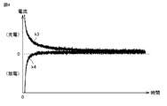
図3,4は、ニッケル水素電池10における自己放電電流を推定する実験結果の一例を示した図である。図3は、ニッケル水素電池10の温度が一定の下でのニッケル水素電池10の電圧の推移を示し、図4は、図3と同条件の温度及び電圧の下でニッケル水素電池10に入出力される電流(電流センサ22の検出値IBa)を示した図である。
<Relationship between the state of the nickel
3 and 4 are diagrams showing examples of experimental results for estimating the self-discharge current in the nickel-
図3及び図4を参照して、ある一定の温度下でニッケル水素電池10の電圧をVcに維持したときにニッケル水素電池10に入出力される電流(電流センサ22の検出値IBa)が示される。図3における線k1は、ニッケル水素電池10の電圧がVcよりも低い状態から電圧をVcに合わせ込んだときの電圧の推移を示し、図4における線k3は、そのときの入出力電流の推移を示す。一方、図3における線k2は、ニッケル水素電池10の電圧がVcよりも高い状態から電圧をVcに合わせ込んだときの電圧の推移を示し、図4における線k4は、そのときの入出力電流の推移を示す。
Referring to FIGS. 3 and 4, the current (detected value IBa of current sensor 22) input / output to / from nickel
図示されるように、ある一定の温度下でニッケル水素電池10の電圧をVcに維持すると、ニッケル水素電池10の入出力電流は、ある一定値(充電方向)に収束する。電圧が一定に維持されていることから、この電流は、ニッケル水素電池10の内部で生じている自己放電による蓄電量の減少を補うものと理解され、すなわち、ニッケル水素電池10における自己放電電流を示しているものと理解される。
As shown in the figure, when the voltage of the nickel
そこで、ニッケル水素電池10の電圧及び温度の条件を変えて、上記の方法によりニッケル水素電池10の状態(電圧及び温度)に応じた自己放電電流を求め、ニッケル水素電池10の状態と自己放電電流との関係を示すデータを求めることができる。
Therefore, the voltage and temperature conditions of the nickel
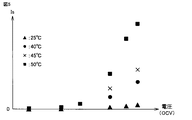
図5は、ニッケル水素電池10の電圧と自己放電電流Isとの相関についての実験結果を示した図である。図5を参照して、横軸は、ニッケル水素電池10の電圧を示し、自己放電電流Isは小さいことから、横軸の電圧は、ニッケル水素電池10のOCVとみなすことができる。図から、自己放電電流Isの電圧依存性が理解され、電圧(OCV)が高いほど自己放電電流Isが大きくなることが分かる。また、同図からは、自己放電電流Isの温度依存性も理解される。
FIG. 5 is a diagram showing experimental results on the correlation between the voltage of the nickel
図6は、ニッケル水素電池10の温度と自己放電電流Isとについてのアレニウスプロットを示した図である。図6を参照して、横軸は、ニッケル水素電池10の温度TBの逆数を示し、縦軸は、自己放電電流Isの自然対数値を示す。●印は、ニッケル水素電池10の電圧(OCV)がVc1である場合のデータであり、◆印は、ニッケル水素電池10の電圧(OCV)がVc2(Vc2>Vc1)である場合のデータである。図から、自己放電電流Isについて、アレニウス則に従う温度依存性が理解される。
FIG. 6 is a diagram showing an Arrhenius plot for the temperature of the nickel
以上のような実験結果に基づいて、ニッケル水素電池10の状態(OCV,温度TB)と自己放電電流Isとの関係を示すデータを求めることができる。
Based on the experimental results as described above, data indicating the relationship between the state (OCV, temperature TB) of the nickel
図7は、ニッケル水素電池10の状態と自己放電電流Isとの関係についてのデータを示した図である。図7を参照して、ニッケル水素電池10の状態は、OCVと温度TBとによって区分され、ニッケル水素電池10の状態(OCV,温度TB)毎に、上記のような実験により自己放電電流Isが求められる。そして、図示されるように、ニッケル水素電池10の状態毎に実験により求められた自己放電電流Isのデータが、たとえばマップとしてECU100のメモリ102(図1)に記憶される。なお、マップに代えて、ニッケル水素電池10の状態(OCV,温度TB)と自己放電電流Isとの関係を示す関係式をメモリ102に記憶してもよい。
FIG. 7 is a diagram showing data on the relationship between the state of the nickel
このようなニッケル水素電池10の状態と自己放電電流Isとの関係を示すデータを実験により予め準備してECU100のメモリ102に記憶しておき、ニッケル水素電池10の状態に応じて自己放電電流Isが推定される。そして、その自己放電電流Isの推定値を電流センサ22の検出値IBa(充電方向を正)から差引くことによって、自己放電の影響が排除された真の電池電流IBが算出され、この電池電流IBの積算値に基づいて第1暫定SOCaが算出される。
Data indicating the relationship between the state of the nickel-
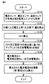
図8は、図2のステップS10において実行される第1暫定SOCa算出処理(電流積算方式)の手順を説明するフローチャートである。 FIG. 8 is a flowchart for explaining the procedure of the first provisional SOCa calculation process (current integration method) executed in step S10 of FIG.
図8を参照して、ECU100は、電圧センサ21、電流センサ22、温度センサ23の各検出値を監視ユニット20から取得する(ステップS110)。次いで、ECU100は、ニッケル水素電池10の分極による電圧上昇量又は電圧降下量を算出する(ステップS120)。なお、ここでいう分極とは、ニッケル水素電池10に負荷電流が流れている場合の、ニッケル水素電池10の内部抵抗による電圧上昇量(充電時)又は電圧降下量(放電時)を示す。すなわち、電流センサ22の検出値にニッケル水素電池10の内部抵抗を乗算することによって、内部抵抗による電圧上昇量(充電時)又は電圧降下量(放電時)を算出することができる。なお、ニッケル水素電池10の内部抵抗は、ニッケル水素電池10の温度依存性が大きく、予め実験等により内部抵抗を温度の関数として求めておくのが好ましい。なお、内部抵抗のSOC依存性が無視できない場合には、内部抵抗の関数にSOC依存項を設けてもよい。
Referring to FIG. 8,
次いで、ECU100は、ステップS120において算出された電圧上昇量(充電時:正値)又は電圧下降量(放電時:負値)を電圧センサ21の検出値VBから差引くことにより、ニッケル水素電池10のOCVを算出する(ステップS130)。そして、ECU100は、ステップS130において算出されたOCVと、温度センサ23によるニッケル水素電池10の温度TBの検出値とから、メモリ102に記憶されたマップ(図7)を用いて自己放電電流Isを推定する(ステップS140)。
Next, the
自己放電電流Isが推定されると、ECU100は、推定された自己放電電流Isを電流センサ22の検出値IBa(電池への入力が正)から差引くことにより、自己放電の影響が排除された真の電池電流IBが算出される(ステップS150)。そして、ECU100は、ステップS150において算出された電池電流IBを積算することによってSOC値の変化量ΔSOCを算出し、その変化量ΔSOCをSOC値の初期値(積算開始時の値)に加えることによって第1暫定SOCaを算出する(ステップS160)。
When the self-discharge current Is is estimated, the
図9〜図12は、自己放電の影響を排除して算出されたSOC値の推定精度の向上効果を説明するための図である。 9 to 12 are diagrams for explaining the effect of improving the estimation accuracy of the SOC value calculated by eliminating the influence of self-discharge.
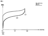
図9〜図11は、SOC値が0%から満充電状態までニッケル水素電池10を充電し、その後、ニッケル水素電池10を完全に放電したときの、第1暫定SOCaの推移を示した図である。図9〜図11の各々において、実線は、第1暫定SOCaの推移を示し、点線は、参考例として、自己放電の影響を考慮していない場合の電流積算に基づくSOC値(すなわち、電流センサ22の検出値IBaを直接積算した場合のSOC値)の推移を示す。実線及び点線の各々において、電圧が高い方の曲線は、充電時の特性を示し(充電カーブ)、電圧が低い方の曲線は、放電時の特性を示す(放電カーブ)。
9 to 11 are diagrams showing the transition of the first provisional SOCa when the nickel
図9は、ニッケル水素電池10の入出力電流の大きさがI1であり、温度TBがT1であるときのSOC値の推移を示す。図10は、ニッケル水素電池10の入出力電流の大きさがI2(I2>I1)であり、温度TBがT1であるときのSOC値の推移を示し、図11は、図10のケースと同じ電流条件(I2)で温度TBがT2(T2>T1)であるときのSOC値の推移を示す。
FIG. 9 shows the transition of the SOC value when the magnitude of the input / output current of the nickel
図9〜図11を参照して、自己放電の影響を考慮していない場合(点線)の放電終了時のSOC値と、原点(充電開始時の点)のSOC値との乖離は、自己放電の影響を意味する。図9に示されるケース(IBa=I1、TB=T1)では、上記乖離はA%である。図10に示されるケース(IBa=I2(I2>I1)、TB=T1)では、上記乖離はB%であり、AとBとの大きさの関係はA>Bである。これは、入出力電流が小さいほど、充放電時間が長いため、相対的に自己放電の影響が大きくなるからである。また、図11に示されるケース(IBa=I2、TB=T2(T2>T1))では、上記乖離はC%であり、BとCとの大きさの関係はB<Cである。これは、ニッケル水素電池10の温度が高いときほど、自己放電電流Isが大きくなるためである。すなわち、高温の場合ほど、自己放電電流Isが大きくなり、SOC値の推定誤差も大きくなることを示している。
9 to 11, the difference between the SOC value at the end of discharge when the influence of self-discharge is not considered (dotted line) and the SOC value at the origin (point at the start of charging) is self-discharge. Means the effect. In the case shown in FIG. 9 (IBa = I1, TB = T1), the deviation is A%. In the case shown in FIG. 10 (IBa = I2 (I2> I1), TB = T1), the divergence is B%, and the relationship between the sizes of A and B is A> B. This is because the smaller the input / output current is, the longer the charge / discharge time is, and thus the greater the influence of self-discharge. In the case shown in FIG. 11 (IBa = I2, TB = T2 (T2> T1)), the deviation is C%, and the relationship between the sizes of B and C is B <C. This is because the self-discharge current Is increases as the temperature of the nickel
これに対して、図8に示したフローチャートによって算出される、この実施の形態による第1暫定SOCa(実線)には、上記のような誤差は見られず、自己放電の影響が排除されており、SOC値の推定精度が向上することが示されている(図9〜図11の各々において、実線は、原点から始まり、原点に戻っている。)。 On the other hand, in the first provisional SOCa (solid line) according to this embodiment calculated by the flowchart shown in FIG. 8, the above error is not seen, and the influence of self-discharge is eliminated. , The estimation accuracy of the SOC value is improved (in each of FIGS. 9 to 11, the solid line starts from the origin and returns to the origin).
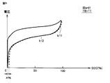
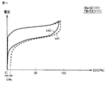
図12は、車両1の走行中におけるSOC値の推移の一例を示した図である。図12を参照して、実線k6は、図8に示したフローチャートによって算出される、この実施の形態による第1暫定SOCaの推移を示し、点線k5は、参考例として、自己放電の影響を考慮していない場合の電流積算に基づくSOC値(すなわち、電流センサ22の検出値IBaを直接積算した場合のSOC値)の推移を示す。
FIG. 12 is a diagram illustrating an example of the transition of the SOC value while the vehicle 1 is traveling. Referring to FIG. 12, a solid line k6 indicates the transition of the first provisional SOCa according to this embodiment calculated by the flowchart shown in FIG. 8, and a dotted line k5 considers the influence of self-discharge as a reference example. The transition of the SOC value based on the current integration when not being performed (that is, the SOC value when the detection value IBa of the
この実施の形態に従う電池システム2において算出される第1暫定SOCa(実線k6)は、自己放電の影響を考慮していない場合のSOC値(点線k5)よりも、自己放電の影響が排除される分だけ低い値を示しており、走行後に実測した残存容量の結果(図示せず)に近い値を示す。
The first provisional SOCa (solid line k6) calculated in the
以上のように、この実施の形態においては、ニッケル水素電池10の状態(OCV,温度TB)とニッケル水素電池10における自己放電電流Isとの関係を示すデータが予め準備されてECU100のメモリ102に記憶される。そして、そのデータを参照して、ニッケル水素電池10の状態から自己放電電流Isが推定され、その推定値を電流センサ22の検出値IBaから差引くことによって得られる値を積算した積算値を用いてSOC値が算出される。これにより、自己放電の影響が排除された真の電池電流に基づいてSOC値が算出される。したがって、この実施の形態に従う電池システム2によれば、ニッケル水素電池10の副反応(自己放電反応)による影響を考慮してSOC値の推定精度を向上させることができる。
As described above, in this embodiment, data indicating the relationship between the state of the nickel metal hydride battery 10 (OCV, temperature TB) and the self-discharge current Is in the nickel
なお、上述のように、自己放電は、放電時・充電時・無負荷時に拘わらず生じており、すなわち、車両1の放置期間(不使用期間)中にも、自己放電は生じている。そこで、車両1のシステムがオフ(以下「IG−OFF」とも称する。)されてから、次回にシステムがオン(以下「IG−ON」とも称する。)されるまでの自己放電電流Isを推定し、その推定結果に基づいて、放置期間中のSOC値の変化(低下量)を推定することができる。これにより、IG−ON時のSOC値(初期値)を精度よく推定することができる。 As described above, self-discharge occurs regardless of discharge, charge, or no load, that is, self-discharge also occurs during the vehicle 1 leaving period (non-use period). Therefore, the self-discharge current Is from when the system of the vehicle 1 is turned off (hereinafter also referred to as “IG-OFF”) to when the system is turned on (hereinafter also referred to as “IG-ON”) is estimated. Based on the estimation result, the change (decrease amount) in the SOC value during the leaving period can be estimated. Thereby, the SOC value (initial value) at the time of IG-ON can be estimated accurately.
たとえば、放置期間中においても、監視ユニット20(図1)によってニッケル水素電池10の電圧VB及び温度TBを検知可能であれば、走行中と同様に、上述の方法によりSOC値を高精度に推定することができる。
For example, if the voltage VB and temperature TB of the nickel-
放置期間中に監視ユニット20によってニッケル水素電池10の電圧VB及び温度TBを取得できない場合には、たとえば、放置期間中のニッケル水素電池10の電圧及び温度の時間変化を線形或いは指数の関数等として仮定し、IG−ON時に、放置期間中の電圧及び温度の推定値に基づいて放置期間中の自己放電電流Isを推定してもよい。すなわち、IG−OFF時の時刻並びにニッケル水素電池10の電圧及び温度をメモリ102に記憶し、IG−ON時に、放置期間中の電圧及び温度を時々刻々と推定するとともに、その推定結果及び図7に示したマップを用いて放置期間中の自己放電電流Isを時々刻々と推定してもよい。そして、その推定した自己放電電流Isを放置期間について積算することにより、放置期間中のSOC変化量を推定してもよい。
In the case where the voltage VB and temperature TB of the nickel
なお、上記の実施の形態では、電流積算方式によるSOC値(第1暫定SOCa)、及び電圧方式によるSOC値(第2暫定SOCb)を適宜重み付けすることによって制御用SOC値を算出するものとしたが、電流積算方式によるSOC値(第1暫定SOCa)をそのまま制御用SOC値として用いてもよい。 In the above embodiment, the SOC value for control is calculated by appropriately weighting the SOC value by the current integration method (first provisional SOCa) and the SOC value by the voltage method (second provisional SOCb). However, the SOC value (first provisional SOCa) by the current integration method may be used as it is as the control SOC value.
今回開示された実施の形態は、すべての点で例示であって制限的なものではないと考えられるべきである。本発明の範囲は、上記した実施の形態の説明ではなくて特許請求の範囲によって示され、特許請求の範囲と均等の意味及び範囲内でのすべての変更が含まれることが意図される。 The embodiment disclosed this time should be considered as illustrative in all points and not restrictive. The scope of the present invention is shown not by the above description of the embodiment but by the scope of claims, and is intended to include all modifications within the meaning and scope equivalent to the scope of claims.
1 車両、2 電池システム、10 ニッケル水素電池、20 監視ユニット、21 電圧センサ、22 電流センサ、23 温度センサ、30 PCU、41,42 MG、50 エンジン、60 動力分割装置、70 駆動軸、80 駆動輪、100 ECU、101 CPU、102 メモリ、103 タイマ。 DESCRIPTION OF SYMBOLS 1 Vehicle, 2 Battery system, 10 Nickel hydrogen battery, 20 Monitoring unit, 21 Voltage sensor, 22 Current sensor, 23 Temperature sensor, 30 PCU, 41, 42 MG, 50 Engine, 60 Power split device, 70 Drive shaft, 80 drive Wheel, 100 ECU, 101 CPU, 102 memory, 103 timer.
Claims (1)
前記ニッケル水素電池の入出力電流を検出する電流センサと、
前記ニッケル水素電池の電流積算値を用いて前記ニッケル水素電池の蓄電量を算出する制御装置とを備え、
前記制御装置は、
前記ニッケル水素電池の状態と前記ニッケル水素電池における自己放電電流との関係を示すデータを記憶し、
前記データを参照して、前記ニッケル水素電池の状態から前記自己放電電流を推定し、
前記自己放電電流の推定値を前記電流センサの検出値から差引くことによって得られる値を積算した積算値を用いて前記蓄電量を算出する、電池システム。 A nickel metal hydride battery,
A current sensor for detecting an input / output current of the nickel metal hydride battery;
A controller for calculating the amount of electricity stored in the nickel-metal hydride battery using the integrated current value of the nickel-metal hydride battery,
The controller is
Storing data indicating the relationship between the state of the nickel metal hydride battery and the self-discharge current in the nickel metal hydride battery;
With reference to the data, the self-discharge current is estimated from the state of the nickel metal hydride battery,
A battery system that calculates the storage amount using an integrated value obtained by integrating values obtained by subtracting an estimated value of the self-discharge current from a detection value of the current sensor.
Priority Applications (1)
| Application Number | Priority Date | Filing Date | Title |
|---|---|---|---|
| JP2016117960A JP6658321B2 (en) | 2016-06-14 | 2016-06-14 | Battery system |
Applications Claiming Priority (1)
| Application Number | Priority Date | Filing Date | Title |
|---|---|---|---|
| JP2016117960A JP6658321B2 (en) | 2016-06-14 | 2016-06-14 | Battery system |
Publications (2)
| Publication Number | Publication Date |
|---|---|
| JP2017223496A true JP2017223496A (en) | 2017-12-21 |
| JP6658321B2 JP6658321B2 (en) | 2020-03-04 |
Family
ID=60687062
Family Applications (1)
| Application Number | Title | Priority Date | Filing Date |
|---|---|---|---|
| JP2016117960A Active JP6658321B2 (en) | 2016-06-14 | 2016-06-14 | Battery system |
Country Status (1)
| Country | Link |
|---|---|
| JP (1) | JP6658321B2 (en) |
Cited By (2)
| Publication number | Priority date | Publication date | Assignee | Title |
|---|---|---|---|---|
| JP2019113469A (en) * | 2017-12-26 | 2019-07-11 | トヨタ自動車株式会社 | Self-discharge inspection method for power storage device |
| CN111442933A (en) * | 2020-04-23 | 2020-07-24 | 厦门金龙联合汽车工业有限公司 | Fuel cell passenger car collision safety detection device and control method thereof |
Citations (10)
| Publication number | Priority date | Publication date | Assignee | Title |
|---|---|---|---|---|
| JPS61209373A (en) * | 1985-03-14 | 1986-09-17 | Matsushita Electric Works Ltd | Circuit for confirming residual power quantity in battery |
| JPH05341023A (en) * | 1992-06-10 | 1993-12-24 | Mitsubishi Motors Corp | Residual capacity calculating method for nickel type battery |
| JPH06205541A (en) * | 1991-10-30 | 1994-07-22 | Texas Instr Inc <Ti> | Battery system |
| JPH07128416A (en) * | 1993-11-04 | 1995-05-19 | Mitsubishi Motors Corp | Battery remaining capacity gauge for electric automobile |
| JPH10509579A (en) * | 1994-11-10 | 1998-09-14 | デュラセル インク | Smart battery device |
| JPH10509857A (en) * | 1994-10-04 | 1998-09-22 | デュラセル インク | Smart battery algorithm for reporting battery parameters to external devices |
| US6072299A (en) * | 1998-01-26 | 2000-06-06 | Medtronic Physio-Control Manufacturing Corp. | Smart battery with maintenance and testing functions |
| JP2002305021A (en) * | 2001-04-03 | 2002-10-18 | Japan Storage Battery Co Ltd | Manufacturing method and storing method of lead-acid battery of ready use |
| JP2004132949A (en) * | 2002-05-15 | 2004-04-30 | General Motors Corp <Gm> | Charge condition algorithm for lead acid storage battery in hybrid electric vehicle |
| US20170153290A1 (en) * | 2015-11-30 | 2017-06-01 | Battelle Energy Alliance, Llc. | Systems and related methods for determining self-discharge currents and internal shorts in energy storage cells |
-
2016
- 2016-06-14 JP JP2016117960A patent/JP6658321B2/en active Active
Patent Citations (10)
| Publication number | Priority date | Publication date | Assignee | Title |
|---|---|---|---|---|
| JPS61209373A (en) * | 1985-03-14 | 1986-09-17 | Matsushita Electric Works Ltd | Circuit for confirming residual power quantity in battery |
| JPH06205541A (en) * | 1991-10-30 | 1994-07-22 | Texas Instr Inc <Ti> | Battery system |
| JPH05341023A (en) * | 1992-06-10 | 1993-12-24 | Mitsubishi Motors Corp | Residual capacity calculating method for nickel type battery |
| JPH07128416A (en) * | 1993-11-04 | 1995-05-19 | Mitsubishi Motors Corp | Battery remaining capacity gauge for electric automobile |
| JPH10509857A (en) * | 1994-10-04 | 1998-09-22 | デュラセル インク | Smart battery algorithm for reporting battery parameters to external devices |
| JPH10509579A (en) * | 1994-11-10 | 1998-09-14 | デュラセル インク | Smart battery device |
| US6072299A (en) * | 1998-01-26 | 2000-06-06 | Medtronic Physio-Control Manufacturing Corp. | Smart battery with maintenance and testing functions |
| JP2002305021A (en) * | 2001-04-03 | 2002-10-18 | Japan Storage Battery Co Ltd | Manufacturing method and storing method of lead-acid battery of ready use |
| JP2004132949A (en) * | 2002-05-15 | 2004-04-30 | General Motors Corp <Gm> | Charge condition algorithm for lead acid storage battery in hybrid electric vehicle |
| US20170153290A1 (en) * | 2015-11-30 | 2017-06-01 | Battelle Energy Alliance, Llc. | Systems and related methods for determining self-discharge currents and internal shorts in energy storage cells |
Cited By (2)
| Publication number | Priority date | Publication date | Assignee | Title |
|---|---|---|---|---|
| JP2019113469A (en) * | 2017-12-26 | 2019-07-11 | トヨタ自動車株式会社 | Self-discharge inspection method for power storage device |
| CN111442933A (en) * | 2020-04-23 | 2020-07-24 | 厦门金龙联合汽车工业有限公司 | Fuel cell passenger car collision safety detection device and control method thereof |
Also Published As
| Publication number | Publication date |
|---|---|
| JP6658321B2 (en) | 2020-03-04 |
Similar Documents
| Publication | Publication Date | Title |
|---|---|---|
| US11009556B2 (en) | Method of estimating deteriorated state of secondary battery and secondary battery system | |
| EP3103672B1 (en) | Hybrid vehicle and control method thereof | |
| US8102146B2 (en) | Remaining-amount estimation device and method for secondary battery | |
| JP5413507B2 (en) | VEHICLE CONTROL DEVICE AND VEHICLE CONTROL METHOD | |
| US20120326655A1 (en) | Charging apparatus for electric storage device, vehicle equipped with the charging apparatus, and method of controlling the charging apparatus | |
| US11332118B2 (en) | Electric motor vehicle and control method for electric motor vehicle | |
| US20190198941A1 (en) | Secondary battery system and method for controlling secondary battery | |
| US20110068740A1 (en) | Power supply system for vehicle, electric vehicle having the same, and method of controlling power supply system for vehicle | |
| US11183856B2 (en) | Battery system, electrically-powered vehicle and control method for electrically-powered vehicle | |
| JP6834757B2 (en) | Battery system | |
| US10850624B2 (en) | Control of fuel consumption in a hybrid vehicle | |
| JP2019100754A (en) | Secondary battery degradation state estimation method and secondary battery system | |
| US10862174B2 (en) | Secondary battery system and method of estimating deterioration state of secondary battery system | |
| JP6790573B2 (en) | Battery system | |
| US11635470B2 (en) | Secondary battery system and SOC estimation method for secondary battery | |
| US11251473B2 (en) | Secondary battery system and control method for secondary battery | |
| JP6658321B2 (en) | Battery system | |
| JP6879136B2 (en) | Charge / discharge control device for secondary batteries | |
| JP5772209B2 (en) | Charge / discharge control device for power storage device and electric vehicle equipped with the same | |
| JP6753332B2 (en) | Battery system | |
| JP2019021417A (en) | Secondary battery system | |
| JP2017221076A (en) | Cell system | |
| JP2018152269A (en) | Battery system | |
| JP2022115363A (en) | battery system | |
| JP2016171624A (en) | Electric vehicle |
Legal Events
| Date | Code | Title | Description |
|---|---|---|---|
| A621 | Written request for application examination |
Free format text: JAPANESE INTERMEDIATE CODE: A621 Effective date: 20180724 |
|
| A977 | Report on retrieval |
Free format text: JAPANESE INTERMEDIATE CODE: A971007 Effective date: 20190517 |
|
| A131 | Notification of reasons for refusal |
Free format text: JAPANESE INTERMEDIATE CODE: A131 Effective date: 20190611 |
|
| A521 | Request for written amendment filed |
Free format text: JAPANESE INTERMEDIATE CODE: A523 Effective date: 20190801 |
|
| TRDD | Decision of grant or rejection written | ||
| A01 | Written decision to grant a patent or to grant a registration (utility model) |
Free format text: JAPANESE INTERMEDIATE CODE: A01 Effective date: 20200107 |
|
| A61 | First payment of annual fees (during grant procedure) |
Free format text: JAPANESE INTERMEDIATE CODE: A61 Effective date: 20200120 |
|
| R151 | Written notification of patent or utility model registration |
Ref document number: 6658321 Country of ref document: JP Free format text: JAPANESE INTERMEDIATE CODE: R151 |