JP2017223489A - Survey system - Google Patents
Survey system Download PDFInfo
- Publication number
- JP2017223489A JP2017223489A JP2016117721A JP2016117721A JP2017223489A JP 2017223489 A JP2017223489 A JP 2017223489A JP 2016117721 A JP2016117721 A JP 2016117721A JP 2016117721 A JP2016117721 A JP 2016117721A JP 2017223489 A JP2017223489 A JP 2017223489A
- Authority
- JP
- Japan
- Prior art keywords
- tracking
- scanner
- target
- light
- unit
- Prior art date
- Legal status (The legal status is an assumption and is not a legal conclusion. Google has not performed a legal analysis and makes no representation as to the accuracy of the status listed.)
- Granted
Links
Images


Classifications
-
- G—PHYSICS
- G01—MEASURING; TESTING
- G01C—MEASURING DISTANCES, LEVELS OR BEARINGS; SURVEYING; NAVIGATION; GYROSCOPIC INSTRUMENTS; PHOTOGRAMMETRY OR VIDEOGRAMMETRY
- G01C15/00—Surveying instruments or accessories not provided for in groups G01C1/00 - G01C13/00
- G01C15/002—Active optical surveying means
-
- G—PHYSICS
- G01—MEASURING; TESTING
- G01C—MEASURING DISTANCES, LEVELS OR BEARINGS; SURVEYING; NAVIGATION; GYROSCOPIC INSTRUMENTS; PHOTOGRAMMETRY OR VIDEOGRAMMETRY
- G01C3/00—Measuring distances in line of sight; Optical rangefinders
- G01C3/02—Details
- G01C3/04—Adaptation of rangefinders for combination with telescopes or binoculars
-
- G—PHYSICS
- G01—MEASURING; TESTING
- G01S—RADIO DIRECTION-FINDING; RADIO NAVIGATION; DETERMINING DISTANCE OR VELOCITY BY USE OF RADIO WAVES; LOCATING OR PRESENCE-DETECTING BY USE OF THE REFLECTION OR RERADIATION OF RADIO WAVES; ANALOGOUS ARRANGEMENTS USING OTHER WAVES
- G01S17/00—Systems using the reflection or reradiation of electromagnetic waves other than radio waves, e.g. lidar systems
- G01S17/02—Systems using the reflection of electromagnetic waves other than radio waves
- G01S17/06—Systems determining position data of a target
- G01S17/42—Simultaneous measurement of distance and other co-ordinates
-
- G—PHYSICS
- G01—MEASURING; TESTING
- G01S—RADIO DIRECTION-FINDING; RADIO NAVIGATION; DETERMINING DISTANCE OR VELOCITY BY USE OF RADIO WAVES; LOCATING OR PRESENCE-DETECTING BY USE OF THE REFLECTION OR RERADIATION OF RADIO WAVES; ANALOGOUS ARRANGEMENTS USING OTHER WAVES
- G01S17/00—Systems using the reflection or reradiation of electromagnetic waves other than radio waves, e.g. lidar systems
- G01S17/66—Tracking systems using electromagnetic waves other than radio waves
-
- G—PHYSICS
- G01—MEASURING; TESTING
- G01S—RADIO DIRECTION-FINDING; RADIO NAVIGATION; DETERMINING DISTANCE OR VELOCITY BY USE OF RADIO WAVES; LOCATING OR PRESENCE-DETECTING BY USE OF THE REFLECTION OR RERADIATION OF RADIO WAVES; ANALOGOUS ARRANGEMENTS USING OTHER WAVES
- G01S17/00—Systems using the reflection or reradiation of electromagnetic waves other than radio waves, e.g. lidar systems
- G01S17/87—Combinations of systems using electromagnetic waves other than radio waves
-
- G—PHYSICS
- G01—MEASURING; TESTING
- G01S—RADIO DIRECTION-FINDING; RADIO NAVIGATION; DETERMINING DISTANCE OR VELOCITY BY USE OF RADIO WAVES; LOCATING OR PRESENCE-DETECTING BY USE OF THE REFLECTION OR RERADIATION OF RADIO WAVES; ANALOGOUS ARRANGEMENTS USING OTHER WAVES
- G01S17/00—Systems using the reflection or reradiation of electromagnetic waves other than radio waves, e.g. lidar systems
- G01S17/88—Lidar systems specially adapted for specific applications
- G01S17/89—Lidar systems specially adapted for specific applications for mapping or imaging
Landscapes
- Physics & Mathematics (AREA)
- Engineering & Computer Science (AREA)
- Electromagnetism (AREA)
- General Physics & Mathematics (AREA)
- Radar, Positioning & Navigation (AREA)
- Remote Sensing (AREA)
- Computer Networks & Wireless Communication (AREA)
- Optical Radar Systems And Details Thereof (AREA)
- Measurement Of Optical Distance (AREA)
Abstract
Description
本発明は、測量現場の三次元データを取得する測量システムに関する。 The present invention relates to a surveying system that acquires three-dimensional data of a surveying site.
近年、立体物の三次元測量が頻繁に行われており、立体物の三次元データ付き画像への需要が増えている。そのため、測量現場では、レーザスキャナを使用して、パルスレーザを所定の測定エリアに走査し、パルスレーザ照射点の三次元位置データを測距して、測定エリアの点群データを取得している(例えば特許文献1参照)。 In recent years, three-dimensional surveys of three-dimensional objects are frequently performed, and the demand for images with three-dimensional data of three-dimensional objects is increasing. For this reason, at the surveying site, a laser scanner is used to scan a pulse laser in a predetermined measurement area, and the three-dimensional position data of the pulse laser irradiation point is measured to obtain point cloud data of the measurement area. (For example, refer to Patent Document 1).
しかし、従来のレーザスキャナでは、測定したい立体物の点群データを十分に得るためには、測定エリアを好適に設定する必要があり、特に、詳細に点群データを得たい場合にはより綿密な設定が必要であった。 However, with a conventional laser scanner, in order to obtain sufficient point cloud data of a three-dimensional object to be measured, it is necessary to set a measurement area suitably, particularly when detailed point cloud data is to be obtained. Needed to be set.
本発明は、面倒な設定をすることなく、測定したい立体物の点群データを取得することのできる測量システムを提供することを目的とする。 An object of the present invention is to provide a surveying system that can acquire point cloud data of a three-dimensional object to be measured without troublesome settings.
上記課題を解決するために、本発明のある態様の測量システムは、追尾光を出射しターゲットで反射した前記追尾光を受光して前記ターゲットを追尾する追尾部を有する測量機と、前記測量機と一体に水平回転し、一軸回りに鉛直方向に走査するスキャナと、を備え、前記スキャナと前記追尾部は水平方向にオフセットされたことを特徴とする。 In order to solve the above problems, a survey system according to an aspect of the present invention includes a surveying instrument that has a tracking unit that emits tracking light and receives the tracking light reflected by a target and tracks the target, and the surveying instrument And a scanner that scans in a vertical direction around one axis, and the scanner and the tracking unit are offset in the horizontal direction.
上記態様において、前記スキャナの光軸は、前記測量機の水平回転軸上にあり、前記追尾光の光軸から水平方向に固定角θだけオフセットされるのも好ましい。 In the above aspect, it is preferable that the optical axis of the scanner is on a horizontal rotation axis of the surveying instrument and is offset from the optical axis of the tracking light by a fixed angle θ in the horizontal direction.
上記態様において、前記スキャナの光軸は、前記測量機の水平回転軸上になく、前記追尾部の光軸に対して水平方向に距離dだけオフセットされるのも好ましい。 In the above aspect, it is preferable that the optical axis of the scanner is not on the horizontal rotation axis of the surveying instrument but is offset by a distance d in the horizontal direction with respect to the optical axis of the tracking unit.
上記態様において、前記測量機は測距光を出射し前記ターゲットで反射した前記測距光を受光して前記ターゲットまでの測距および測角を行う測定部をさらに備え、前記スキャナの光軸は、前記測量機の水平回転軸上にあり、前記追尾部は追尾送光部と追尾受光部を備え、前記追尾光の反射光の像が常に前記追尾受光部の画像上の所定位置にくるように追尾し、前記スキャナの反射光の像は前記追尾受光部の画像上で前記所定位置から少なくとも水平方向にオフセットされた位置で検出するのも好ましい。 In the above aspect, the surveying instrument further includes a measuring unit that emits ranging light and receives the ranging light reflected by the target to measure the distance to the target and measure the angle, and the optical axis of the scanner is The tracking unit includes a tracking light transmitting unit and a tracking light receiving unit so that the reflected light image of the tracking light is always at a predetermined position on the image of the tracking light receiving unit. It is also preferable that the reflected light image of the scanner is detected at a position offset at least in the horizontal direction from the predetermined position on the image of the tracking light receiving unit.
上記態様において、前記測量システムは測定した前記ターゲットの高度角付近の点群データ以外は取得しないのも好ましい。 In the above aspect, it is also preferable that the surveying system does not acquire any data other than the point cloud data near the measured altitude angle of the target.
本発明の測量システムによれば、面倒な設定をすることなく、測定したい立体物の点群データを取得することができる。 According to the surveying system of the present invention, it is possible to acquire point cloud data of a three-dimensional object to be measured without troublesome settings.
次に、本発明の好適な実施の形態について、図面を参照して説明する。 Next, preferred embodiments of the present invention will be described with reference to the drawings.
(第1の実施形態)
図1は第1の実施の形態に係る測量システムの外観斜視図である。図1における符号1が、本形態に係る測量システムである。測量システム1は、外観上は、測量機2と、スキャナ22を有する。符号9は、測量機2のターゲットであるプリズムである。
(First embodiment)
FIG. 1 is an external perspective view of the surveying system according to the first embodiment.
図2は測量システム1の制御ブロック図である。測量システム1は、水平角検出器11と、鉛直角検出器12と、水平回転駆動部13と、鉛直回転駆動部14と、表示部15と、操作部16と、演算制御部17と、追尾光送光部18と、追尾光受光部19と、測定部20と、記憶部21と、スキャナ22とを備える。
FIG. 2 is a control block diagram of the
水平角検出器11、鉛直角検出器12、水平回転駆動部13、鉛直回転駆動部14、演算制御部17、および記憶部21は、測量機2の托架部2b(後述)に収容され、表示部15と操作部16は托架部2bの外部に設けられている。追尾光送光部18、追尾光受光部19、および測定部20は、測量機2の望遠鏡2a(後述)に収容されている。スキャナ22は、後述する配置で望遠鏡2aに固定されている。
The
測量機2は、いわゆるモータドライブトータルステーションであり、三脚を用いて既知の点に据え付けられている。測量機2は、下方から、整準部と、整準部の上に設けられた基盤部と、該基盤部上を水平回転軸H-H周りに回転する托架部2bと、托架部2bの中央で鉛直回転軸V-V周りに回転する望遠鏡2aと、を有する。
The
水平回転駆動部13と鉛直回転駆動部14はモータであり、演算制御部17に制御されて、それぞれ水平回転軸H−Hと鉛直回転軸V-Vを駆動する。測量機2では、托架部2bの水平回転と望遠鏡2aの鉛直回転の協働により、望遠鏡2aから測距光または追尾光が出射される。
The horizontal
表示部15と操作部16は、測量システム1のインターフェースであり、測量作業の指令・設定や作業状況および測定結果の確認などが行える。
The
水平角検出器11と鉛直角検出器12は、回転円盤、スリット、発光ダイオード、イメージセンサを有するアブソリュートエンコーダまたはインクリメンタルエンコーダである。水平角検出器11は水平回転軸H−Hに対して設けられ托架部2bの水平方向の回転角を検出する。鉛直角検出器12は鉛直回転軸V-Vに対して設けられ望遠鏡2aの鉛直方向の回転角を検出する。
The
追尾光送光部18は、測距光とは異なる波長の赤外レーザ等を追尾光として出射する。図1の符号4は、追尾光の光軸を示している。追尾光の光軸4は、測量機2の水平回転軸H-H上となるように設計されている。追尾光受光部19は、イメージセンサであり、例えばCCDセンサ又はCMOSセンサである。追尾光受光部19は、追尾光を含む風景画像と追尾光を除いた風景画像を取得する。両画像は、演算制御部17に送られる。演算制御部17では、両画像の差分からターゲット像の中心を求め、ターゲット像の中心と望遠鏡2aの視軸中心からの隔たりが一定値以内に収まる位置をターゲットの位置として検出し、常に望遠鏡2aがターゲットの方向を向くように自動で追尾を行う。追尾光送光部18、追尾光受光部19および演算制御部17が「追尾部」である。
The tracking
測定部20は、測距光送光部と測距光受光部を備え、例えば赤外レーザ等の測距光をターゲットに射出しその反射光を受光する。そして、追尾部と同様に、測距光を含む画像と除いた画像の差分からターゲットを捕捉し、視準が完了するとターゲットまでの測距と測角を行う。
The
スキャナ22は、いわゆる一軸レーザスキャナであり、符号5はある時間のスキャナ22の光軸を示し、符号10はその時の照射点(測定位置)を示している。スキャナ22は、一軸の回転軸R-R周りにパルスレーザを照射しその反射光を検出して、パルスレーザ光線毎に測距・測角を行って、点群データを取得する。
The
演算制御部17は、例えばCPU,ROM,RAM等を集積回路に実装したマイクロコントローラであり、回転駆動部13,14の制御、測定部20および追尾部の発光制御を行い、ターゲットの自動追尾、自動視準、測距および測角を行い、測量データを得る。また、スキャナ22の回転制御、発光制御を行い、照射点10の点群データを取得する。記憶部21は、例えばハードディスクドライブであり、上記演算制御のためのプログラムが格納されており、取得した測量データおよび点群データが記憶される。
The
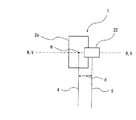
測量システム1は、以上の要素を有するとともに、次の配置を有する。測量システム1では、図1に示すように、スキャナ22は、回転軸R-Rが水平方向に延在し、鉛直方向のスキャンラインSLが得られるように配置される。さらに、スキャナ22は、図3は測量システム1の平面図であるが、図3に示すように、スキャナの光軸5は測量機2の水平回転軸H-H上にあり、かつ、スキャナの光軸5が追尾光の光軸4から水平方向に固定角θだけオフセットするように望遠鏡2aの上部に固定される。なお、固定角θは、スキャナ22がプリズム9をスキャンすることがない角度であって、最小限の値で設定されているのが好ましい。
The
以上の測量システム1を使用すると、次のように点群データを取得することができる。
When the
まず、測量システム1で、追尾プログラムを実行する。この上で、スキャナ22による測量プログラムも開始する。すると、自動追尾により望遠鏡2aは常にプリズム9を向くように制御される。望遠鏡2aに固定されているスキャナ22も、望遠鏡2と同様にプリズム9のほうを向くこととなるが、スキャナの光軸5が追尾光の光軸4から水平方向に固定角θだけオフセットしているため、スキャンラインSLはプリズム9と一致することはなく、常にプリズム9の周辺(プリズム9から距離を隔てた位置)で制御される。(図1に示す矢印は、プリズム9の移動に伴いスキャンラインSLが移動する様子を示している)。測量機2の座標系でみた照射点10の三次元位置は、固定角θの値は予め分かっているため、測量機2の水平角検出器11および鉛直角検出器12で得た回転角、およびスキャナ22での測距値から計算することができる。
First, a tracking program is executed by the
上述のように、測量システム1を用いれば、プリズム9をスキャンすることなく、プリズム9の動きに合わせてスキャンラインSLを移動させることができる。即ち、ターゲット付近でスキャンラインSLを制御できるため、測定エリアを設定しなくても、測定対象物およびその周辺のデータを取得することができる。
As described above, if the
また、次のような使用をすることもできる。測量システム1を用いれば、ある場所の点群データを取得したい場合、その場所でターゲットを往復させれば、自動追尾がなされて、測定エリアを設定しなくてもその場所の点群データを取得することができる。即ち、測定したい場所でターゲットを移動させることで、測定エリアを能動的に決めることができる。このとき、表示部15または有線無線を問わずに接続されたパーソナルコンピュータ等に、取得した点群データをリアルタイムで表示すれば、その場でスキャン密度を確認しながら測量することができる。
Moreover, it can also be used as follows. Using the
(第2の実施の形態)
図4は第2の実施の形態に係る測量システム1の平面図である。第1の実施形態と同一の要素については同一の符号を用いて説明を割愛する。第2の実施形態では、スキャナの光軸5と追尾光の光軸4は平行で、スキャナの光軸5は測量機2の水平回転軸H-H上に無い。その代わり、スキャナ22は、スキャナの光軸5が追尾光の光軸4から水平方向に距離dだけオフセットするように、望遠鏡2aの上部に固定される。
(Second Embodiment)
FIG. 4 is a plan view of the
第2の実施形態では、スキャナ22が望遠鏡2a(追尾部)に対して水平方向にオフセットした位置に固定されているので、スキャンラインSLがプリズム9と一致することはなく、常にプリズム9の周辺(プリズム9から距離を隔てた位置)で制御される。測量機2の座標系でみた照射点10の三次元位置は、オフセット距離dの値は予め分かっているため、測量機2の水平角検出器11および鉛直角検出器12で得た回転角およびスキャナ22での測距値から計算することができる。このため、第1の実施形態と同様、測定エリアを設定しなくても、測定対象物およびその周辺のデータを取得することができ、測定したい場所でターゲットを移動させることで測定エリアを能動的に決めることができる。
In the second embodiment, since the
なお、スキャナ22を固定する位置は、図示の位置に限定されるものではなく、スキャナの光軸5が追尾光の光軸4から水平方向にオフセットしていれば、どの位置、距離であってもよい。測量機2のデザインが許せば、望遠鏡2aの下部でも、側部であっても、または測量機2本体の下部(例えば表示部15の下)であってもよい。
The position where the
(第3の実施の形態)
第3の実施形態では、スキャナの光軸5は図3のように測量機2の水平回転軸H-H上とし、固定角θは0を含む任意の角度としてよい。第1の実施形態と同一の要素については同一の符号を用いて説明を割愛する。
(Third embodiment)
In the third embodiment, the
図5は第3の実施の形態に係る測量システム1により取得した画像の図である。図5は、追尾光受光部19で取得した画像であり、符号8は追尾光の反射光の像である。スキャナ光と追尾光は異なる波長を採用しているため、追尾受光部19にはスキャナの像は写らない。従って、図5では、実際には写らないが、スキャナ光を、スキャンラインSLとして仮想的に図示している。符号Oは、追尾受光部19の画像中心を示している。そして、第3の実施形態では、追尾光の反射光の像8はスキャンラインSLから水平方向に所定距離離れた位置Sに映るように制御がなされる。
FIG. 5 is a diagram of an image acquired by the
即ち、第3の実施形態では、追尾光の反射光の像8(ターゲット像の中心)が位置Sから一定値以内に収まる位置をターゲット位置として検出し、追尾を行う。そして、ターゲットまでの距離に応じて、追尾受光部19の位置Sを可変し、実際での追尾光の光軸4とスキャナの光軸5の角度θ3を任意に変えることで、実際でのターゲット(プリズム9)と照射点10の間隔を常に固定距離Dだけオフセットさせることができる。上記ターゲットまでの距離は、例えば(1)追尾開始時には画像中心Oの位置で追尾し、測定部20で測距し、取得した値に応じて追尾位置(位置S)を決定し、以降は位置Sを変更しない、(2)追尾開始時に画像中心Oを追尾し、測定部20で測距し、その後追尾位置(位置S)を変更してからは、遠近によるプリズム像の大小を測定して距離を出す、(3)追尾中に時々追尾位置を画像中心Oに戻して測距する、ことで得られる。なお、図5の破線は、スキャナの光軸5を追尾光の光軸4と同じ平面上に投影させた線である。このように、追尾イメージセンサ上の追尾位置を水平方向にずらすことでも、スキャンラインSLを常にプリズム9に対して固定距離Dだけオフセットした位置で制御することができる。このため、第1の実施形態と同様、測定エリアを設定しなくても、測定対象物およびその周辺のデータを取得することができ、測定したい場所でターゲットを移動させることで測定エリアを能動的に決めることができる。なお、少なくとも水平方向に離れていればよく、鉛直方向にずれていてもよい。即ち、追尾イメージセンサ上の追尾位置をスキャナの検出位置から固定角だけオフセットさせてもよい。
That is, in the third embodiment, the tracking light is detected by detecting the position where the reflected light image 8 (the center of the target image) falls within a certain value from the position S as the target position. Then, depending on the distance to the target, the position S of the tracking
上記実施の形態に対する好適な変形例について述べる。上記実施の形態と同一の要素については同一の符号を用いて説明を割愛する。 A preferred modification to the above embodiment will be described. The description of the same elements as those in the above embodiment is omitted by using the same reference numerals.
(変形例1)
トータルステーションである測量機2は、プリズム9の測距・測角値から、プリズム9の高度角を測定することができる。そこで、変形例1の測量システム1では、プリズム9の高度角を中心に鉛直方向上下に所定角拡張したエリア以外の点群データは、記憶部21に保存しないようにする。図6は変形例1を説明する図である。図6に示す矢印は、プリズム9の移動に伴いスキャンラインSLが移動する様子を示している。符号31はプリズム9の高度角に相当する位置の水平ラインを示しており、符号32は水平ライン31から鉛直方向に±α(数°〜数十°)拡張した水平ラインを示している。即ち、変形例1では、スキャンラインSLの軌跡と拡張した水平ライン32・32で囲まれる測定エリア(図6の斜線のエリア)の点群データを保存し、この測定エリア以外の点群データは保存しない。これにより、保存するデータ量を減らすことができる。なお、測定エリアの鉛直方向の範囲を規定するαは、上述のように角度でもよいし、例えば±1mなど、長さで設定されてもよい。長さの場合、距離に応じて角度が自動に決定されるように設定すればよい。
(Modification 1)
The surveying
(変形例2)
測量システム1では、スキャナ22のレーザ光線は、非可視光でも可視光でもよいが、非可視光の場合、照射点10が作業者には分からないという問題がある。そこで、スキャナの光軸5と水平方向に光軸を一致させた可視光のラインレーザを、例えば測量機2の本体下部に設けて、ガイド光として出射するのも好ましい。これにより、スキャン方向が作業者に明確となる。
(Modification 2)
In the
(変形例3)
測量システム1では、スキャナ22は鉛直方向に走査されるが、サンプリング位置が固定されていると、往復してスキャンを繰り返しても、鉛直角が同じ位置の点群データしか得られないおそれがある。そこで、走査の開始点を微小角ずつずらすのも好ましい。例えば、往復運動の折り返し時にスキャナ22のレーザ光の発光タイミングをランダムにずらす、または規則的に例えば0.5secずつずらしていけば、行きと帰りで走査のサンプリング位置(鉛直角)が異なるので、より緻密できれいに点群データを得ることができる。
(Modification 3)
In the
以上、本発明の好ましい測量システムについて、実施の形態および変形例を述べたが、各形態および各変形を当業者の知識に基づいて組み合わせることが可能であり、そのような形態も本発明の範囲に含まれる。 The preferred embodiment of the surveying system according to the present invention and the modified examples have been described above. However, the embodiments and the modifications can be combined based on the knowledge of those skilled in the art, and such forms are also within the scope of the present invention. include.
1 測量システム
2 測量機
2a 望遠鏡
4 追尾光の光軸
5 スキャナの光軸
7 追尾光の反射光の像
8 スキャナの反射光の像
9 プリズム(ターゲット)
10 照射点
17 演算制御部(追尾部)
18 追尾光送光部(追尾部)
19 追尾光受光部(追尾部)
20 測定部
21 記憶部
22 スキャナ
H-H線 測量機の水平回転軸
DESCRIPTION OF
10
18 Tracking light transmission part (tracking part)
19 Tracking light receiving unit (tracking unit)
20 Measuring
Claims (5)
前記測量機と一体に水平回転し、一軸回りに鉛直方向に走査するスキャナと、を備え、
前記スキャナと前記追尾部は水平方向にオフセットされたことを特徴とする測量システム。
A surveying instrument having a tracking unit that emits tracking light and receives the tracking light reflected by the target and tracks the target;
A scanner that rotates horizontally with the surveying instrument and scans in a vertical direction around one axis;
The surveying system, wherein the scanner and the tracking unit are offset in the horizontal direction.
The surveying system according to claim 1, wherein an optical axis of the scanner is on a horizontal rotation axis of the surveying instrument and is offset by a fixed angle θ in the horizontal direction from the optical axis of the tracking light.
The surveying system according to claim 1, wherein the optical axis of the scanner is not on the horizontal rotation axis of the surveying instrument but is offset by a distance d in the horizontal direction with respect to the optical axis of the tracking unit.
The surveying instrument further includes a measuring unit that emits ranging light and receives the ranging light reflected by the target to measure the distance to the target and measure the angle, and the optical axis of the scanner includes the surveying instrument The tracking unit includes a tracking light transmitting unit and a tracking light receiving unit, and tracks the reflected light image of the tracking light so as to always be at a predetermined position on the image of the tracking light receiving unit, The survey system according to claim 1, wherein the reflected light image of the scanner is detected at a position offset at least in the horizontal direction from the predetermined position on the image of the tracking light receiving unit.
Priority Applications (3)
| Application Number | Priority Date | Filing Date | Title |
|---|---|---|---|
| JP2016117721A JP6713847B2 (en) | 2016-06-14 | 2016-06-14 | Surveying system |
| US15/619,079 US10591290B2 (en) | 2016-06-14 | 2017-06-09 | Survey system |
| EP17175616.6A EP3258290B1 (en) | 2016-06-14 | 2017-06-13 | Survey system |
Applications Claiming Priority (1)
| Application Number | Priority Date | Filing Date | Title |
|---|---|---|---|
| JP2016117721A JP6713847B2 (en) | 2016-06-14 | 2016-06-14 | Surveying system |
Publications (2)
| Publication Number | Publication Date |
|---|---|
| JP2017223489A true JP2017223489A (en) | 2017-12-21 |
| JP6713847B2 JP6713847B2 (en) | 2020-06-24 |
Family
ID=59055063
Family Applications (1)
| Application Number | Title | Priority Date | Filing Date |
|---|---|---|---|
| JP2016117721A Active JP6713847B2 (en) | 2016-06-14 | 2016-06-14 | Surveying system |
Country Status (3)
| Country | Link |
|---|---|
| US (1) | US10591290B2 (en) |
| EP (1) | EP3258290B1 (en) |
| JP (1) | JP6713847B2 (en) |
Cited By (3)
| Publication number | Priority date | Publication date | Assignee | Title |
|---|---|---|---|---|
| JP2019113507A (en) * | 2017-12-26 | 2019-07-11 | 株式会社トプコン | Measurement apparatus, measurement control device, measurement control method and measurement control processing program |
| JP2019128196A (en) * | 2018-01-23 | 2019-08-01 | 株式会社トプコン | Surveying apparatus and surveying method |
| JP2020020747A (en) * | 2018-08-03 | 2020-02-06 | 株式会社トプコン | Laser scanner system |
Families Citing this family (4)
| Publication number | Priority date | Publication date | Assignee | Title |
|---|---|---|---|---|
| EP3450915B1 (en) * | 2017-08-30 | 2020-11-25 | Hexagon Technology Center GmbH | Total station or theodolite with scan functionality and adjustable receiving areas of the receiver |
| JP7287793B2 (en) * | 2019-02-26 | 2023-06-06 | 株式会社トプコン | Target device and survey system |
| JP7234011B2 (en) * | 2019-04-02 | 2023-03-07 | 株式会社トプコン | Location information display device and surveying system |
| JP7299669B2 (en) * | 2019-08-28 | 2023-06-28 | 株式会社トプコン | A surveying instrument equipped with a guide light irradiation unit |
Citations (11)
| Publication number | Priority date | Publication date | Assignee | Title |
|---|---|---|---|---|
| JPH11236716A (en) * | 1997-11-10 | 1999-08-31 | Topcon Corp | Construction working machinery automatic control system |
| US20090168045A1 (en) * | 2007-12-28 | 2009-07-02 | Industrial Technology Research Institute | Three-dimensional surround scanning device and method thereof |
| JP2009229192A (en) * | 2008-03-21 | 2009-10-08 | Topcon Corp | Survey instrument, survey system, detection method of to-be-measured object, and detection program of to-be-measured object |
| JP2012047656A (en) * | 2010-08-30 | 2012-03-08 | Hitachi Ltd | Shape measurement method using laser scanner |
| JP2012530909A (en) * | 2009-06-23 | 2012-12-06 | ライカ・ジオシステムズ・アクチェンゲゼルシャフト | TRACKING METHOD AND MEASUREMENT SYSTEM HAVING LASER TRACKER |
| JP2013190272A (en) * | 2012-03-13 | 2013-09-26 | Kyushu Univ | Three-dimensional laser measuring apparatus and three-dimensional laser measuring method |
| US20140300886A1 (en) * | 2013-04-05 | 2014-10-09 | Leica Geosystems Ag | Geodetic referencing of point clouds |
| US20140307252A1 (en) * | 2013-04-12 | 2014-10-16 | Hexagon Technology Center Gmbh | Surveying device |
| US20150098075A1 (en) * | 2013-10-09 | 2015-04-09 | Hexagon Technology Center Gmbh | Scanner for space measurement |
| JP2015125099A (en) * | 2013-12-27 | 2015-07-06 | 株式会社トプコン | Surveying equipment |
| JP2016095150A (en) * | 2014-11-12 | 2016-05-26 | 株式会社トプコン | Inclination detection system and inclination detection method |
Family Cites Families (6)
| Publication number | Priority date | Publication date | Assignee | Title |
|---|---|---|---|---|
| JPS63287063A (en) | 1987-05-19 | 1988-11-24 | Nec Corp | Manufacture of semiconductor device |
| JP5057734B2 (en) | 2006-09-25 | 2012-10-24 | 株式会社トプコン | Surveying method, surveying system, and surveying data processing program |
| JP5150329B2 (en) | 2008-03-26 | 2013-02-20 | 株式会社トプコン | Surveying device and surveying system |
| EP2620745A1 (en) * | 2012-01-30 | 2013-07-31 | Hexagon Technology Center GmbH | Measuring system with a measuring device and a scan module |
| US9746560B2 (en) | 2013-02-12 | 2017-08-29 | Faro Technologies, Inc. | Combination scanner and tracker device having a focusing mechanism |
| US10671066B2 (en) * | 2015-03-03 | 2020-06-02 | PreNav, Inc. | Scanning environments and tracking unmanned aerial vehicles |
-
2016
- 2016-06-14 JP JP2016117721A patent/JP6713847B2/en active Active
-
2017
- 2017-06-09 US US15/619,079 patent/US10591290B2/en active Active
- 2017-06-13 EP EP17175616.6A patent/EP3258290B1/en active Active
Patent Citations (11)
| Publication number | Priority date | Publication date | Assignee | Title |
|---|---|---|---|---|
| JPH11236716A (en) * | 1997-11-10 | 1999-08-31 | Topcon Corp | Construction working machinery automatic control system |
| US20090168045A1 (en) * | 2007-12-28 | 2009-07-02 | Industrial Technology Research Institute | Three-dimensional surround scanning device and method thereof |
| JP2009229192A (en) * | 2008-03-21 | 2009-10-08 | Topcon Corp | Survey instrument, survey system, detection method of to-be-measured object, and detection program of to-be-measured object |
| JP2012530909A (en) * | 2009-06-23 | 2012-12-06 | ライカ・ジオシステムズ・アクチェンゲゼルシャフト | TRACKING METHOD AND MEASUREMENT SYSTEM HAVING LASER TRACKER |
| JP2012047656A (en) * | 2010-08-30 | 2012-03-08 | Hitachi Ltd | Shape measurement method using laser scanner |
| JP2013190272A (en) * | 2012-03-13 | 2013-09-26 | Kyushu Univ | Three-dimensional laser measuring apparatus and three-dimensional laser measuring method |
| US20140300886A1 (en) * | 2013-04-05 | 2014-10-09 | Leica Geosystems Ag | Geodetic referencing of point clouds |
| US20140307252A1 (en) * | 2013-04-12 | 2014-10-16 | Hexagon Technology Center Gmbh | Surveying device |
| US20150098075A1 (en) * | 2013-10-09 | 2015-04-09 | Hexagon Technology Center Gmbh | Scanner for space measurement |
| JP2015125099A (en) * | 2013-12-27 | 2015-07-06 | 株式会社トプコン | Surveying equipment |
| JP2016095150A (en) * | 2014-11-12 | 2016-05-26 | 株式会社トプコン | Inclination detection system and inclination detection method |
Cited By (6)
| Publication number | Priority date | Publication date | Assignee | Title |
|---|---|---|---|---|
| JP2019113507A (en) * | 2017-12-26 | 2019-07-11 | 株式会社トプコン | Measurement apparatus, measurement control device, measurement control method and measurement control processing program |
| JP7060377B2 (en) | 2017-12-26 | 2022-04-26 | 株式会社トプコン | Surveying device, surveying control device, surveying control method and surveying control processing program |
| JP2019128196A (en) * | 2018-01-23 | 2019-08-01 | 株式会社トプコン | Surveying apparatus and surveying method |
| JP7022601B2 (en) | 2018-01-23 | 2022-02-18 | 株式会社トプコン | Surveying equipment and surveying method |
| JP2020020747A (en) * | 2018-08-03 | 2020-02-06 | 株式会社トプコン | Laser scanner system |
| JP7120723B2 (en) | 2018-08-03 | 2022-08-17 | 株式会社トプコン | laser scanner system |
Also Published As
| Publication number | Publication date |
|---|---|
| EP3258290A1 (en) | 2017-12-20 |
| JP6713847B2 (en) | 2020-06-24 |
| US10591290B2 (en) | 2020-03-17 |
| US20170356741A1 (en) | 2017-12-14 |
| EP3258290B1 (en) | 2021-08-25 |
Similar Documents
| Publication | Publication Date | Title |
|---|---|---|
| JP2017223489A (en) | Survey system | |
| EP3264134B1 (en) | Laser scanner system and registration method of point cloud data | |
| JP6963936B2 (en) | Surveying system | |
| EP3514489B1 (en) | Surveying device and surveying method | |
| JP4177765B2 (en) | Surveying system | |
| JP2013190272A (en) | Three-dimensional laser measuring apparatus and three-dimensional laser measuring method | |
| JP2017223540A (en) | Measuring system | |
| US9106805B2 (en) | Image measuring system | |
| JP6786325B2 (en) | Surveying equipment and measuring method | |
| US20200105043A1 (en) | Point cloud data display system | |
| JP7313955B2 (en) | Surveying instrument, surveying method and surveying program | |
| JP6680628B2 (en) | Laser scanner | |
| JP2018009957A (en) | Three-dimensional position measurement system, three-dimensional position measurement method, and measurement module | |
| JP7448397B2 (en) | Surveying equipment and surveying systems | |
| JP7314447B2 (en) | Scanner system and scanning method | |
| JP2017223608A (en) | Surveying device | |
| US20210080577A1 (en) | Three-dimensional survey apparatus, three-dimensional survey method, and three-dimensional survey program | |
| JP6749191B2 (en) | Scanner and surveying equipment | |
| US11692823B2 (en) | Three-dimensional survey apparatus, three-dimensional survey method, and three-dimensional survey program | |
| JP2018048868A (en) | Scanner device and surveying device | |
| JP6913422B2 (en) | Surveying system | |
| JP2021067615A (en) | Scanner system and scan method | |
| US10895456B1 (en) | Three-dimensional survey apparatus, three-dimensional survey method, and three-dimensional survey program | |
| JP6423032B2 (en) | 3D surveying device | |
| JP2022054848A (en) | Tracking method, laser scanner, and tracking program |
Legal Events
| Date | Code | Title | Description |
|---|---|---|---|
| A621 | Written request for application examination |
Free format text: JAPANESE INTERMEDIATE CODE: A621 Effective date: 20190307 |
|
| A977 | Report on retrieval |
Free format text: JAPANESE INTERMEDIATE CODE: A971007 Effective date: 20191224 |
|
| A131 | Notification of reasons for refusal |
Free format text: JAPANESE INTERMEDIATE CODE: A131 Effective date: 20200109 |
|
| A521 | Request for written amendment filed |
Free format text: JAPANESE INTERMEDIATE CODE: A523 Effective date: 20200206 |
|
| TRDD | Decision of grant or rejection written | ||
| A01 | Written decision to grant a patent or to grant a registration (utility model) |
Free format text: JAPANESE INTERMEDIATE CODE: A01 Effective date: 20200603 |
|
| A61 | First payment of annual fees (during grant procedure) |
Free format text: JAPANESE INTERMEDIATE CODE: A61 Effective date: 20200604 |
|
| R150 | Certificate of patent or registration of utility model |
Ref document number: 6713847 Country of ref document: JP Free format text: JAPANESE INTERMEDIATE CODE: R150 |
|
| R250 | Receipt of annual fees |
Free format text: JAPANESE INTERMEDIATE CODE: R250 |