JP2017211911A - Wearable apparatus, wearable apparatus system, control method of wearable apparatus, control device of wearable apparatus, and control program - Google Patents

Wearable apparatus, wearable apparatus system, control method of wearable apparatus, control device of wearable apparatus, and control program Download PDF

Info

Publication number
JP2017211911A
JP2017211911A JP2016106135A JP2016106135A JP2017211911A JP 2017211911 A JP2017211911 A JP 2017211911A JP 2016106135 A JP2016106135 A JP 2016106135A JP 2016106135 A JP2016106135 A JP 2016106135A JP 2017211911 A JP2017211911 A JP 2017211911A
Authority
JP
Japan
Prior art keywords
wearable device
information
user
unit
physical quantity
Prior art date
Legal status (The legal status is an assumption and is not a legal conclusion. Google has not performed a legal analysis and makes no representation as to the accuracy of the status listed.)
Pending
Application number
JP2016106135A
Other languages
Japanese (ja)
Inventor
敦士 石井
Atsushi Ishii
敦士 石井
規理 西川
Tadamichi Nishikawa
規理 西川
Current Assignee (The listed assignees may be inaccurate. Google has not performed a legal analysis and makes no representation or warranty as to the accuracy of the list.)
Kyocera Corp
Original Assignee
Kyocera Corp
Priority date (The priority date is an assumption and is not a legal conclusion. Google has not performed a legal analysis and makes no representation as to the accuracy of the date listed.)
Filing date
Publication date
Application filed by Kyocera Corp filed Critical Kyocera Corp
Priority to JP2016106135A priority Critical patent/JP2017211911A/en
Priority to US16/305,013 priority patent/US11300998B2/en
Priority to PCT/JP2017/019316 priority patent/WO2017204242A1/en
Publication of JP2017211911A publication Critical patent/JP2017211911A/en
Pending legal-status Critical Current

Links

Images

Classifications

    • GPHYSICS
    • G06COMPUTING; CALCULATING OR COUNTING
    • G06FELECTRIC DIGITAL DATA PROCESSING
    • G06F1/00Details not covered by groups G06F3/00 - G06F13/00 and G06F21/00
    • G06F1/16Constructional details or arrangements
    • G06F1/1613Constructional details or arrangements for portable computers
    • G06F1/163Wearable computers, e.g. on a belt
    • AHUMAN NECESSITIES
    • A61MEDICAL OR VETERINARY SCIENCE; HYGIENE
    • A61BDIAGNOSIS; SURGERY; IDENTIFICATION
    • A61B5/00Measuring for diagnostic purposes; Identification of persons
    • A61B5/02Detecting, measuring or recording pulse, heart rate, blood pressure or blood flow; Combined pulse/heart-rate/blood pressure determination; Evaluating a cardiovascular condition not otherwise provided for, e.g. using combinations of techniques provided for in this group with electrocardiography or electroauscultation; Heart catheters for measuring blood pressure
    • A61B5/024Detecting, measuring or recording pulse rate or heart rate
    • A61B5/0245Detecting, measuring or recording pulse rate or heart rate by using sensing means generating electric signals, i.e. ECG signals
    • GPHYSICS
    • G06COMPUTING; CALCULATING OR COUNTING
    • G06FELECTRIC DIGITAL DATA PROCESSING
    • G06F1/00Details not covered by groups G06F3/00 - G06F13/00 and G06F21/00
    • G06F1/16Constructional details or arrangements
    • G06F1/1613Constructional details or arrangements for portable computers
    • G06F1/1633Constructional details or arrangements of portable computers not specific to the type of enclosures covered by groups G06F1/1615 - G06F1/1626
    • G06F1/1684Constructional details or arrangements related to integrated I/O peripherals not covered by groups G06F1/1635 - G06F1/1675
    • G06F1/169Constructional details or arrangements related to integrated I/O peripherals not covered by groups G06F1/1635 - G06F1/1675 the I/O peripheral being an integrated pointing device, e.g. trackball in the palm rest area, mini-joystick integrated between keyboard keys, touch pads or touch stripes
    • GPHYSICS
    • G06COMPUTING; CALCULATING OR COUNTING
    • G06FELECTRIC DIGITAL DATA PROCESSING
    • G06F3/00Input arrangements for transferring data to be processed into a form capable of being handled by the computer; Output arrangements for transferring data from processing unit to output unit, e.g. interface arrangements
    • G06F3/01Input arrangements or combined input and output arrangements for interaction between user and computer
    • G06F3/011Arrangements for interaction with the human body, e.g. for user immersion in virtual reality
    • G06F3/014Hand-worn input/output arrangements, e.g. data gloves
    • GPHYSICS
    • G06COMPUTING; CALCULATING OR COUNTING
    • G06FELECTRIC DIGITAL DATA PROCESSING
    • G06F3/00Input arrangements for transferring data to be processed into a form capable of being handled by the computer; Output arrangements for transferring data from processing unit to output unit, e.g. interface arrangements
    • G06F3/01Input arrangements or combined input and output arrangements for interaction between user and computer
    • G06F3/011Arrangements for interaction with the human body, e.g. for user immersion in virtual reality
    • G06F3/015Input arrangements based on nervous system activity detection, e.g. brain waves [EEG] detection, electromyograms [EMG] detection, electrodermal response detection
    • GPHYSICS
    • G06COMPUTING; CALCULATING OR COUNTING
    • G06FELECTRIC DIGITAL DATA PROCESSING
    • G06F3/00Input arrangements for transferring data to be processed into a form capable of being handled by the computer; Output arrangements for transferring data from processing unit to output unit, e.g. interface arrangements
    • G06F3/01Input arrangements or combined input and output arrangements for interaction between user and computer
    • G06F3/016Input arrangements with force or tactile feedback as computer generated output to the user
    • HELECTRICITY
    • H04ELECTRIC COMMUNICATION TECHNIQUE
    • H04BTRANSMISSION
    • H04B1/00Details of transmission systems, not covered by a single one of groups H04B3/00 - H04B13/00; Details of transmission systems not characterised by the medium used for transmission
    • H04B1/38Transceivers, i.e. devices in which transmitter and receiver form a structural unit and in which at least one part is used for functions of transmitting and receiving
    • H04B1/3827Portable transceivers

Abstract

PROBLEM TO BE SOLVED: To provide a wearable apparatus enabling a user to feel a physical quantity.SOLUTION: A wearable apparatus includes a first communication unit, a stimulation unit, and a first processing unit. The first communication unit receives first information on the basis of a physical quantity. The stimulation unit stimulates a sense organ of a first user's skin by a controllable stimulation quantity. The first processing unit causes the stimulation unit to stimulate the sense organ so that the sense organ reproduces the physical quantity on the basis of the first information.SELECTED DRAWING: Figure 3

Description

本開示は、装着型機器、装着型機器システム、装着型機器の制御方法、装着型機器の制御装置および制御プログラムに関する。   The present disclosure relates to a wearable device, a wearable device system, a wearable device control method, a wearable device control apparatus, and a control program.

特許文献1にも記載されているように、従来から装着型機器に関して様々な技術が提案されている。   As described in Patent Document 1, various techniques have conventionally been proposed for wearable devices.

特開2007−143812号公報JP 2007-143812 A

装着型機器は、ユーザの皮膚の感覚器を刺激するのに適している。なぜなら、ユーザが装着型機器を装着した状態では、装着型機器は直接または衣服を介して、ユーザの皮膚に対面するからである。   The wearable device is suitable for stimulating the sensory organs of the user's skin. This is because, when the user wears the wearable device, the wearable device faces the user's skin directly or through clothes.

しかしながら、装着型機器によるユーザの皮膚の感覚器の刺激方法については、従来、あまり考慮されていなかった。   However, conventionally, a method for stimulating a user's skin sensory organ by a wearable device has not been considered much.

また、ユーザが仮想的な感覚を体験できることが望まれている。言い換えれば、ユーザは物理量(例えば温度など)を体感できることが望まれている。   It is also desired that the user can experience a virtual sense. In other words, it is desired that the user can experience a physical quantity (for example, temperature).

そこで、本発明は、ユーザが物理量を体感できる装着型機器を提供することを目的とする。   Therefore, an object of the present invention is to provide a wearable device that allows a user to experience physical quantities.

装着型機器、装着型機器システム、装着型機器の制御方法、装着型機器の制御装置および制御プログラムが開示される。装着型機器は、第1通信部と、刺激部と、第1処理部とを備える。第1通信部は、物理量に基づく第1情報を受信する。刺激部は、可制御の刺激量で第1ユーザの皮膚の感覚器を刺激する。第1処理部は、第1情報に基づいて、物理量を当該感覚器で再現するように、刺激部に当該感覚器を刺激させる。   A wearable device, a wearable device system, a wearable device control method, a wearable device control apparatus, and a control program are disclosed. The wearable device includes a first communication unit, a stimulation unit, and a first processing unit. The first communication unit receives first information based on a physical quantity. The stimulation unit stimulates the sensory organs of the first user's skin with a controllable amount of stimulation. Based on the first information, the first processing unit causes the stimulation unit to stimulate the sensory device so that the physical quantity is reproduced by the sensory device.

他の一実施の形態では、装着型機器システムは、互いに通信可能な第1装着型機器および第2装着型機器を備える。第1装着型機器はセンサを備える。センサは物理量を検出する。第2装着型機器は、刺激部と、処理部とを備える。刺激部は、可制御の刺激量でユーザの感覚器を刺激する。処理部は、物理量を当該感覚器で再現するように、刺激部に当該感覚器を刺激させる。   In another embodiment, the wearable device system includes a first wearable device and a second wearable device that can communicate with each other. The first wearable device includes a sensor. The sensor detects a physical quantity. The second wearable device includes a stimulation unit and a processing unit. The stimulation unit stimulates the user's sensory organ with a controllable amount of stimulation. The processing unit causes the stimulation unit to stimulate the sensory organ so that the physical quantity is reproduced by the sensory device.

他の一実施の形態では、装着型機器の制御方法は、第1工程と、第2工程とを備える。第1工程においては、物理量に基づく第1情報を受信する。第2工程においては、第1情報に基づいて、物理量をユーザの感覚器で再現するように、刺激部に感覚器を刺激させる。   In another embodiment, a method for controlling a wearable device includes a first step and a second step. In the first step, first information based on a physical quantity is received. In the second step, based on the first information, the stimulation unit is caused to stimulate the sensory device so that the physical quantity is reproduced by the user's sensory device.

他の一実施の形態では、装着型機器は、第1通信部と、刺激部とを備える。第1通信部は、物理量に基づく第1情報を受信する。刺激部は、可制御の刺激量で第1ユーザの皮膚の感覚器を刺激する。装着型機器の制御装置は、第1情報に基づいて、物理量を当該感覚器で再現するように、刺激部に当該感覚器を刺激させる処理部を備える。   In another embodiment, the wearable device includes a first communication unit and a stimulation unit. The first communication unit receives first information based on a physical quantity. The stimulation unit stimulates the sensory organs of the first user's skin with a controllable amount of stimulation. The control device of the wearable device includes a processing unit that causes the stimulating unit to stimulate the sensory device so that the physical quantity is reproduced by the sensory device based on the first information.

他の一実施の形態では、装着型機器は、第1通信部と、刺激部とを備える。第1通信部は、物理量に基づく第1情報を受信する。刺激部は、可制御の刺激量で第1ユーザの皮膚の感覚器を刺激する。制御プログラムは、装着型機器に、第1情報に基づいて、物理量を当該感覚器で再現するように、刺激部に当該感覚器を刺激させる処理を実行させる。   In another embodiment, the wearable device includes a first communication unit and a stimulation unit. The first communication unit receives first information based on a physical quantity. The stimulation unit stimulates the sensory organs of the first user's skin with a controllable amount of stimulation. The control program causes the wearable device to execute a process of causing the stimulating unit to stimulate the sensory device so that the physical quantity is reproduced by the sensory device based on the first information.

ユーザが物理量を体感できる。   Users can experience physical quantities.

装着型機器の外観の一例を概略的に示す斜視図である。It is a perspective view showing an example of appearance of a wearable apparatus roughly. 装着型機器システムの構成の一例を概略的に示す図である。It is a figure which shows roughly an example of a structure of a wearable apparatus system. 装着型機器の電気的な構成の一例を概略的に示す機能ブロック図である。It is a functional block diagram which shows roughly an example of the electrical constitution of a wearable apparatus. 装着型機器の構成の一例を概略的に示す図である。It is a figure which shows an example of a structure of a wearable apparatus roughly. 装着型機器の構成の一例を概略的に示す図である。It is a figure which shows an example of a structure of a wearable apparatus roughly. 装着型機器の構成の一例を概略的に示す図である。It is a figure which shows an example of a structure of a wearable apparatus roughly. 装着型機器の構成の一例を概略的に示す図である。It is a figure which shows an example of a structure of a wearable apparatus roughly. 制御部の内部構成の一例を概略的に示す機能ブロック図である。It is a functional block diagram which shows an example of an internal structure of a control part roughly. 装着型機器システムの構成の一例を概略的に示す図である。It is a figure which shows roughly an example of a structure of a wearable apparatus system. 装着型機器の動作の一例を示すフローチャートである。It is a flowchart which shows an example of operation | movement of a wearable apparatus. 装着型機器の動作の一例を示すフローチャートである。It is a flowchart which shows an example of operation | movement of a wearable apparatus. 装着型機器の電気的な構成の一例を概略的に示す機能ブロック図である。It is a functional block diagram which shows roughly an example of the electrical constitution of a wearable apparatus. 装着型機器の動作の一例を示すフローチャートである。It is a flowchart which shows an example of operation | movement of a wearable apparatus. 装着型機器の動作の一例を示すフローチャートである。It is a flowchart which shows an example of operation | movement of a wearable apparatus. 装着型機器の構成の一例を概略的に示す図である。It is a figure which shows an example of a structure of a wearable apparatus roughly. 装着型機器システムの構成の一例を概略的に示す図である。It is a figure which shows roughly an example of a structure of a wearable apparatus system. 装着型機器の電気的な構成の一例を概略的に示す機能ブロック図である。It is a functional block diagram which shows roughly an example of the electrical constitution of a wearable apparatus. 装着型機器システムの構成の一例を概略的に示す図である。It is a figure which shows roughly an example of a structure of a wearable apparatus system. 装着型機器の動作の一例を示すフローチャートである。It is a flowchart which shows an example of operation | movement of a wearable apparatus. 装着型機器の動作の一例を示すフローチャートである。It is a flowchart which shows an example of operation | movement of a wearable apparatus. 装着型機器の電気的な構成の一例を概略的に示す機能ブロック図である。It is a functional block diagram which shows roughly an example of the electrical constitution of a wearable apparatus. 装着型機器システムの構成の一例を概略的に示す図である。It is a figure which shows roughly an example of a structure of a wearable apparatus system. 装着型機器の動作の一例を示すフローチャートである。It is a flowchart which shows an example of operation | movement of a wearable apparatus. 装着型機器の動作の一例を示すフローチャートである。It is a flowchart which shows an example of operation | movement of a wearable apparatus. センサに対応した再現方法を説明するための図である。It is a figure for demonstrating the reproduction method corresponding to a sensor. 装着型機器システムの構成の一例を概略的に示す図である。It is a figure which shows roughly an example of a structure of a wearable apparatus system. 装着型機器システムの構成の一例を概略的に示す図である。It is a figure which shows roughly an example of a structure of a wearable apparatus system. 装着型機器の電気的な構成の一例を概略的に示す機能ブロック図である。It is a functional block diagram which shows roughly an example of the electrical constitution of a wearable apparatus. 装着型機器の動作の一例を示すフローチャートである。It is a flowchart which shows an example of operation | movement of a wearable apparatus. 位置および加速度との関係の一例を概略的に示す図である。It is a figure which shows roughly an example of the relationship between a position and acceleration. 装着型機器の動作の一例を示すフローチャートである。It is a flowchart which shows an example of operation | movement of a wearable apparatus. 装着型機器の構成の一例を概略的に示す図である。It is a figure which shows an example of a structure of a wearable apparatus roughly. 装着型機器の構成の一例を概略的に示す図である。It is a figure which shows an example of a structure of a wearable apparatus roughly. 装着型機器の構成の一例を概略的に示す図である。It is a figure which shows an example of a structure of a wearable apparatus roughly. 装着型機器の構成の一例を概略的に示す図である。It is a figure which shows an example of a structure of a wearable apparatus roughly. 装着型機器の構成の一例を概略的に示す図である。It is a figure which shows an example of a structure of a wearable apparatus roughly. 装着型機器の構成の一例を概略的に示す図である。It is a figure which shows an example of a structure of a wearable apparatus roughly.

<装着型機器の外観>
図1は、装着型機器1の外観の一例を概略的に示す斜視図である。この装着型機器1はユーザに装着される。図1の例示では、装着型機器1として、腕輪型の機器が示されている。ただし、装着型機器1は必ずしもこれに限らない。例えば装着型機器1は、指輪型、イヤホン型、ヘッドフォン型などの任意の装着型機器であってよい。以下では、一例として、装着型機器1が腕輪型の機器である場合について説明する。
<Appearance of wearable device>
FIG. 1 is a perspective view schematically showing an example of the appearance of the wearable device 1. This wearable device 1 is worn by a user. In the illustration of FIG. 1, a bracelet type device is shown as the wearable device 1. However, the wearable device 1 is not necessarily limited to this. For example, the wearable device 1 may be any wearable device such as a ring type, an earphone type, or a headphone type. Below, the case where the wearable apparatus 1 is a bracelet apparatus is demonstrated as an example.

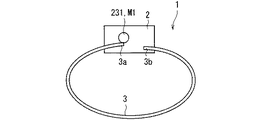
図1の例示では、装着型機器1は、本体部2と、バンド部3とを備えている。バンド部3は帯状の板状形状を有しており、その両端が本体部2に取り付けられている。これにより、装着型機器1は環状の形状を形成する。ユーザは、装着型機器1のバンド部3を腕に嵌めることによって、装着型機器1を装着することができる。   In the illustration of FIG. 1, the wearable device 1 includes a main body portion 2 and a band portion 3. The band part 3 has a belt-like plate shape, and both ends thereof are attached to the main body part 2. Thereby, the wearable device 1 forms an annular shape. The user can wear the wearable device 1 by fitting the band portion 3 of the wearable device 1 to the arm.

本体部2は、後述する機械的構成および電気的構成を収納している。例えば本体部2は平板状の形状を有していてもよい。図1に例示するように、本体部2は、例えば長方形の板状形状を有していてもよい。   The main body 2 stores a mechanical configuration and an electrical configuration described later. For example, the main body 2 may have a flat plate shape. As illustrated in FIG. 1, the main body 2 may have, for example, a rectangular plate shape.

また、図1に例示するように、この本体部2の外周側の表面には、例えば表示領域251が設けられてもよい。この表示領域251には、後述する表示部25によって種々の情報が表示される。ユーザはこの表示領域251を視認することにより、種々の情報を知ることができる。例えば、表示部25は時刻を表示領域251に表示してもよい。表示部25が時刻を表示する場合には、装着型機器1はいわゆる腕時計としても機能する。   Moreover, as illustrated in FIG. 1, for example, a display region 251 may be provided on the outer peripheral surface of the main body 2. Various information is displayed in the display area 251 by the display unit 25 described later. The user can know various information by visually recognizing the display area 251. For example, the display unit 25 may display the time in the display area 251. When the display unit 25 displays the time, the wearable device 1 also functions as a so-called wristwatch.

<システムの概要>
図2は、装着型機器システム100の構成の一例を概略的に示す図である。図2に例示するように、装着型機器システム100は複数の装着型機器1を備えている。図2の例示では、2つの装着型機器1が示されている。これらの装着型機器1は互いに通信可能である。なお、装着型機器1は相互に直接に通信してもよく、あるいは、不図示の外部装置(例えば、スマートフォンなどの携帯機器、基地局およびサーバの少なくともいずれか一つ)を介して通信してもよい。
<System overview>
FIG. 2 is a diagram schematically illustrating an example of the configuration of the wearable device system 100. As illustrated in FIG. 2, the wearable device system 100 includes a plurality of wearable devices 1. In the illustration of FIG. 2, two wearable devices 1 are shown. These wearable devices 1 can communicate with each other. The wearable device 1 may communicate directly with each other, or communicate with each other via an unillustrated external device (for example, at least one of a mobile device such as a smartphone, a base station, and a server). Also good.

以下では、これら2つの装着型機器1を区別すべく、それぞれを装着型機器1A,1Bと呼ぶことがある。装着型機器1AはユーザUAに装着され、装着型機器1BはユーザUBに装着される。図2の例示では、それぞれ装着型機器1A,1BがユーザUA,UBの腕(例えば手首)に装着されている。   Hereinafter, these two wearable devices 1 may be referred to as wearable devices 1A and 1B in order to distinguish them. The wearable device 1A is worn by the user UA, and the wearable device 1B is worn by the user UB. In the illustration of FIG. 2, the wearable devices 1A and 1B are respectively worn on the arms (for example, wrists) of the users UA and UB.

<装着型機器の電気的構成>
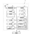
図3は、装着型機器1の電気的構成の一例を概略的に示す機能ブロック図である。装着型機器1は、制御部21と、無線通信部22と、刺激部23と、入力部24と、表示部25と、センサ26と、電池27とを備えている。
<Electrical configuration of wearable device>
FIG. 3 is a functional block diagram schematically showing an example of the electrical configuration of the wearable device 1. The wearable device 1 includes a control unit 21, a wireless communication unit 22, a stimulation unit 23, an input unit 24, a display unit 25, a sensor 26, and a battery 27.

制御部21は例えば本体部2に収納されている。この制御部21は、一種の演算処理装置であって、一種の電気回路でもある。制御部21は、例えば、CPU(Central Processing Unit)211、DSP(Digital Signal Processor)212及び記憶媒体213等を備えている。制御部21は、装着型機器1の他の構成要素を制御することによって、装着型機器1の動作を統括的に管理することが可能である。制御部21は、例えば、SoC(System-on-a-Chip)、MCU(Micro Control Unit)及びFPGA(Field-Programmable Gate Array)等の副処理装置(co-processor)をさらに含んでも良い。この場合には、制御部21は、CPU211及び副処理装置を互いに協働させて各種の制御を行って良いし、両者を切り替えながら用いて各種の制御を行って良い。制御部21は制御装置とも言える。   The control unit 21 is accommodated in the main body 2, for example. The control unit 21 is a kind of arithmetic processing device, and is also a kind of electric circuit. The control unit 21 includes, for example, a CPU (Central Processing Unit) 211, a DSP (Digital Signal Processor) 212, a storage medium 213, and the like. The control unit 21 can comprehensively manage the operation of the wearable device 1 by controlling other components of the wearable device 1. The control unit 21 may further include, for example, a sub-processing device (co-processor) such as an SoC (System-on-a-Chip), an MCU (Micro Control Unit), and an FPGA (Field-Programmable Gate Array). In this case, the control unit 21 may perform various types of control by causing the CPU 211 and the sub-processing device to cooperate with each other, or may perform various types of control while switching between the two. The control unit 21 can also be said to be a control device.

記憶媒体213は、RAM(Random Access Memory)などの揮発性メモリ213aと、フラッシュROM(Read Only Memory)などの不揮発性メモリ213bとを備えている。揮発性メモリ213a及び不揮発性メモリ213bのそれぞれは、CPU211及びDSP212が読み取り可能な非一時的な記憶媒体である。不揮発性メモリ213bには、装着型機器1を制御するための複数の制御プログラムPg1が記憶されている。制御部21の各種機能は、CPU211及びDSP212が記憶媒体213内の各種制御プログラムPg1を実行することによって実現される。   The storage medium 213 includes a volatile memory 213a such as a RAM (Random Access Memory) and a non-volatile memory 213b such as a flash ROM (Read Only Memory). The volatile memory 213a and the non-volatile memory 213b are non-transitory storage media that can be read by the CPU 211 and the DSP 212, respectively. The non-volatile memory 213b stores a plurality of control programs Pg1 for controlling the wearable device 1. Various functions of the control unit 21 are realized by the CPU 211 and the DSP 212 executing various control programs Pg1 in the storage medium 213.

なお、制御部21の全ての機能あるいは制御部21の一部の機能は、その機能の実現にソフトウェアが不要なハードウェア回路によって実現されても良い。要するに、制御部21は回路によって構成されていればよい。また、記憶媒体213は、ROM及びRAM以外の、コンピュータが読み取り可能な非一時的な記憶媒体を備えても良い。記憶媒体213は、例えば、小型のハードディスクドライブ及びSSD(Solid State Drive)などを備えても良い。   It should be noted that all the functions of the control unit 21 or some functions of the control unit 21 may be realized by a hardware circuit that does not require software to realize the function. In short, the control part 21 should just be comprised by the circuit. The storage medium 213 may include a computer-readable non-transitory storage medium other than the ROM and RAM. The storage medium 213 may include, for example, a small hard disk drive and an SSD (Solid State Drive).

また記憶媒体213とともに、あるいは、記憶媒体213に替えて、別の記憶媒体が制御部21の外部に設けられてもよい。後述する情報の記憶先は記憶媒体213であってもよく、制御部21の外部の記憶媒体であってもよい。   Further, another storage medium may be provided outside the control unit 21 together with the storage medium 213 or instead of the storage medium 213. The storage destination of information to be described later may be the storage medium 213 or a storage medium outside the control unit 21.

無線通信部(通信回路)22は例えば本体部2に収納されており、アンテナ221を有している。無線通信部22は、アンテナ221を用いて、制御部21による制御よって無線通信を行うことが可能である。無線通信部22は、装着型機器1とは別の装着型機器1からの信号を、例えば基地局等を介して、または、直接に、アンテナ221で受信することが可能である。無線通信部22は、受信信号に対して増幅処理及びダウンコンバートを行って制御部21に出力することが可能である。制御部21は、入力される受信信号に対して復調処理等を行って、当該受信信号に含まれるユーザデータ及び制御データ等を取得することが可能である。また無線通信部22は、制御部21で生成された送信信号に対してアップコンバート及び増幅処理を行って、処理後の送信信号をアンテナ221から無線送信することが可能である。アンテナ221からの送信信号は、例えば基地局等を介して、または、直接に、別の装着型機器1で受信される。   The wireless communication unit (communication circuit) 22 is accommodated in the main body 2, for example, and has an antenna 221. The wireless communication unit 22 can perform wireless communication using the antenna 221 under the control of the control unit 21. The wireless communication unit 22 can receive a signal from the wearable device 1 different from the wearable device 1 via the antenna 221 via, for example, a base station or the like. The wireless communication unit 22 can perform amplification processing and down-conversion on the received signal and output it to the control unit 21. The control unit 21 can perform demodulation processing or the like on the input reception signal and acquire user data, control data, and the like included in the reception signal. The wireless communication unit 22 can up-convert and amplify the transmission signal generated by the control unit 21 and wirelessly transmit the processed transmission signal from the antenna 221. A transmission signal from the antenna 221 is received by another wearable device 1 via, for example, a base station or directly.

刺激部23は、装着型機器1がユーザに装着された状態において、可制御の刺激量でユーザの皮膚の感覚器を刺激することができる。また、この刺激部23は制御部21によって制御される。皮膚の感覚器には、触覚、圧覚または温度覚に対応する受容器が含まれており、刺激部23はこの受容器に対して刺激を与えることが可能である。   The stimulation unit 23 can stimulate the sensory organs of the user's skin with a controllable stimulation amount in a state where the wearable device 1 is worn by the user. The stimulation unit 23 is controlled by the control unit 21. The sensory organs of the skin include a receptor corresponding to a tactile sensation, a pressure sensation, or a temperature sensation, and the stimulation unit 23 can give stimulation to the receptor.

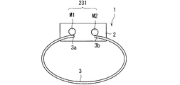
図3の例示では、刺激部23は、バンド部3と、締付機構231とを備えている。バンド部3はユーザの体の一部(例えば腕)に巻き付けられる。締付機構231は、バンド部3を用いて、可制御の締め付け力でユーザの体の当該一部(例えば腕)を締め付けることができる。換言すれば、この刺激部23は、ユーザの皮膚の圧覚の受容器を可制御の刺激量で刺激することが可能である。   In the illustration of FIG. 3, the stimulation unit 23 includes a band unit 3 and a tightening mechanism 231. The band unit 3 is wound around a part of the user's body (for example, an arm). The tightening mechanism 231 can tighten the part (for example, an arm) of the user's body with a controllable tightening force using the band unit 3. In other words, the stimulation unit 23 can stimulate the pressure sensory receptor on the user's skin with a controllable amount of stimulation.

図4は、装着型機器1の構成の一例を概略的に示す図である。図4の例示では、主として刺激部23に関する構成要素が示されており、これ以外の構成要素については、図の煩雑を避けるために、適宜に図示を省略している。後に参照する図5〜図7についても同様である。図4に例示するように、締付機構231は例えば本体部2に収納されている。この締付機構231は例えばモータM1を有していてもよい。このモータM1は制御部21によって制御されて回転する。モータM1は任意のモータであってよく、例えば直流モータまたは交流モータであってよい。例えば電池27とモータM1との間に、所定の電力変換部が設けられてもよい。この電力変換部は、制御部21によって制御されて、電池27からの電圧を所望の電圧に変換し、変換後の電圧をモータM1へと出力する。モータM1はこの電圧に応じて回転する。   FIG. 4 is a diagram schematically illustrating an example of the configuration of the wearable device 1. In the illustration of FIG. 4, components related to the stimulation unit 23 are mainly illustrated, and other components are not illustrated as appropriate in order to avoid complication of the drawing. The same applies to FIGS. 5 to 7 referred to later. As illustrated in FIG. 4, the tightening mechanism 231 is accommodated in the main body 2, for example. For example, the tightening mechanism 231 may include a motor M1. The motor M1 is controlled by the control unit 21 and rotates. The motor M1 may be any motor, for example, a DC motor or an AC motor. For example, a predetermined power conversion unit may be provided between the battery 27 and the motor M1. This power conversion unit is controlled by the control unit 21, converts the voltage from the battery 27 into a desired voltage, and outputs the converted voltage to the motor M1. The motor M1 rotates according to this voltage.

モータM1には、バンド部3の一端3aが固定されている。またバンド部3の他端3bは、例えば本体部2の内部において、固定されている。このバンド部3は外力によって、主として自身の法線方向に、湾曲変形することが可能である。よって、モータM1が所定方向(図4では時計回り)に回転することにより、モータM1はバンド部3の一部を巻き取ることができる。このようなバンド部3は例えば弾性材料(例えば合成樹脂)、繊維(例えば合成繊維)または金属などの材料によって形成できる。   One end 3a of the band portion 3 is fixed to the motor M1. Further, the other end 3 b of the band part 3 is fixed, for example, inside the main body part 2. The band portion 3 can be bent and deformed mainly in its normal direction by an external force. Therefore, when the motor M1 rotates in a predetermined direction (clockwise in FIG. 4), the motor M1 can wind up a part of the band portion 3. Such a band portion 3 can be formed of a material such as an elastic material (for example, synthetic resin), a fiber (for example, synthetic fiber), or a metal.

図5は、装着型機器1の構成の一例を概略的に示している。図5の例示では、モータM1には、バンド部3の一部が巻き付いている。つまり、バンド部3がモータM1によって巻き取られている。よって、バンド部3のうち本体部2から延びる部分の周の長さは、図4の装着型機器1のそれに比べて短い。つまり、モータM1がバンド部3の一部を巻き取ることによって、バンド部3がユーザの腕を締め付けることができる。制御部21は、例えばモータM1の出力トルクを制御することで、締め付け力を制御することができる。   FIG. 5 schematically shows an example of the configuration of the wearable device 1. In the illustration of FIG. 5, a part of the band part 3 is wound around the motor M1. That is, the band part 3 is wound up by the motor M1. Therefore, the circumferential length of the portion extending from the main body 2 in the band 3 is shorter than that of the wearable device 1 in FIG. That is, when the motor M1 winds up a part of the band part 3, the band part 3 can tighten the user's arm. For example, the control unit 21 can control the tightening force by controlling the output torque of the motor M1.

逆に、モータM1が所定方向とは反対方向に回転することにより、本体部2から延びるバンド部3の周の長さが長くなる。これにより、モータM1はバンド部3による腕の締め付けを緩めることができる。   On the contrary, when the motor M1 rotates in the direction opposite to the predetermined direction, the length of the circumference of the band portion 3 extending from the main body portion 2 becomes longer. Thereby, the motor M1 can loosen the arm tightening by the band portion 3.

このような刺激部23は、バンド部3による締め付けおよび緩和により、ユーザの腕の皮膚の例えば圧覚の受容器を刺激することができる。つまり、ユーザは、バンド部3による締め付け具合を知覚することができる。   Such a stimulating unit 23 can stimulate, for example, a pressure sensation receptor on the skin of the user's arm by tightening and relaxing by the band unit 3. That is, the user can perceive the degree of tightening by the band part 3.

なお上述の例では、締付機構231が、本体部2から延びるバンド部3の周の長さを変更することで、バンド部3による締め付けを制御しているものの、必ずしもこれに限らない。例えばバンド部3の厚みが変更可能となるようにバンド部3が構成され、締付機構231がこの厚みを変更することによって、バンド部3による締め付けを制御してもよい。   In the above example, the tightening mechanism 231 controls the tightening by the band unit 3 by changing the circumferential length of the band unit 3 extending from the main body unit 2, but is not necessarily limited thereto. For example, the band unit 3 may be configured such that the thickness of the band unit 3 can be changed, and the tightening mechanism 231 may control the tightening by the band unit 3 by changing the thickness.

図6は、装着型機器1の構成の他の一例を概略的に示す図である。図6の例示では、締付機構231は例えばポンプPP1を有している。ポンプPP1は制御部21によって制御される。バンド部3は、その厚みが膨張可能となるように形成されている。例えば、バンド部3は合成樹脂(例えばポリエチレン系などの樹脂)、弾性材料(例えばゴム)または繊維(例えば合成繊維)などの材料によって構成されており、その内部にポンプPP1に連なる内部空間が形成されている。例えば、この内部空間は、ポンプPP1との連結部のみにおいて開口している。要するに、内部空間は、ポンプPP1に開口した袋状に形成される。ポンプPP1は外部からの空気を当該内部空間に送り込んだり、内部空間の空気を外部へと吐出することができる。   FIG. 6 is a diagram schematically illustrating another example of the configuration of the wearable device 1. In the illustration of FIG. 6, the tightening mechanism 231 includes, for example, a pump PP1. The pump PP1 is controlled by the control unit 21. The band portion 3 is formed so that its thickness can be expanded. For example, the band portion 3 is made of a material such as a synthetic resin (for example, a polyethylene-based resin), an elastic material (for example, rubber), or a fiber (for example, a synthetic fiber), and an internal space connected to the pump PP1 is formed therein. Has been. For example, this internal space is opened only at the connecting portion with the pump PP1. In short, the internal space is formed in a bag shape opened to the pump PP1. The pump PP1 can send air from the outside into the internal space and can discharge the air in the internal space to the outside.

この内部空間へと、ポンプPP1によって空気が送り込まれることによって、バンド部3は少なくとも内周側に膨張する。なお、バンド部3は内周側および外周側の両方に膨張してもよい。図7は、バンド部3が膨張した状態における装着型機器1の構成の他の一例を概略的に示している。バンド部3が内周側に向けて膨張するので、バンド部3が囲む空間が狭くなる。つまり、ポンプPP1はバンド部3を用いてユーザの腕を締め付けることができる。制御部21はポンプPP1による空気の流量を制御することで、締め付け力を制御することができる。一方で、ポンプPP1が内部空間の空気を吸い込むことによって、バンド部3はその厚み方向に収縮する。これにより、バンド部3が囲む空間が広がる。つまり、ポンプPP1はバンド部3によるユーザの腕の締め付けを緩めることができる。   When the air is fed into the internal space by the pump PP1, the band portion 3 expands at least on the inner peripheral side. The band portion 3 may expand both on the inner peripheral side and on the outer peripheral side. FIG. 7 schematically shows another example of the configuration of the wearable device 1 in a state where the band portion 3 is expanded. Since the band part 3 expand | swells toward an inner peripheral side, the space which the band part 3 surrounds becomes narrow. That is, the pump PP1 can tighten the user's arm using the band portion 3. The controller 21 can control the tightening force by controlling the flow rate of air from the pump PP1. On the other hand, when the pump PP1 sucks air in the internal space, the band portion 3 contracts in the thickness direction. Thereby, the space which the band part 3 surrounds spreads. That is, the pump PP1 can loosen the tightening of the user's arm by the band portion 3.

なお、バンド部3による締め付けの為には、バンド部3のうち内周側の部材が膨張および収縮できればよい。要するに、バンド部3のうち内周側の部材が、例えばポリエチレン系などの合成樹脂、弾性材料(例えばゴム)または繊維(例えば合成繊維)などの材料によって形成されればよい。   In addition, in order to tighten by the band part 3, the member of the inner peripheral side among the band parts 3 should just be able to expand and shrink | contract. In short, the member on the inner peripheral side of the band portion 3 may be formed of a material such as a synthetic resin such as polyethylene, an elastic material (for example, rubber), or a fiber (for example, a synthetic fiber).

また上述の例では、バンド部3の厚みを、空気という流体を用いて制御しているものの必ずしもこれに限らない。例えばバンド部3の厚みを機械的に制御してもよい。具体的な一例として、いわゆるZ軸ステージのような、回転を厚みに変換する装置を利用してもよい。当該装置に対する回転は、モータによって与えられてもよい。この場合、モータが回転することで、当該装置の厚みが変化する。   Moreover, in the above-mentioned example, although the thickness of the band part 3 is controlled using the fluid called air, it is not necessarily restricted to this. For example, the thickness of the band portion 3 may be controlled mechanically. As a specific example, an apparatus that converts rotation into thickness, such as a so-called Z-axis stage, may be used. The rotation for the device may be provided by a motor. In this case, the thickness of the device changes as the motor rotates.

そして、当該装置の厚みがバンド部3の厚み方向に沿うように、当該装置をバンド部3の内部に設ける。例えばバンド部3を袋状に構成し、その内部に当該装置を収納する。当該装置は複数設けられてもよい。この場合、例えば、当該装置の複数を周方向に沿って配置してもよい。そして、制御部21がモータを制御することにより、当該装置の厚み、ひいてはバンド部3の厚みを制御する。これにより、ユーザの腕の締め付け、および、緩和を制御することができる。   Then, the device is provided inside the band unit 3 so that the thickness of the device is along the thickness direction of the band unit 3. For example, the band portion 3 is formed in a bag shape, and the device is accommodated therein. A plurality of such devices may be provided. In this case, for example, a plurality of the devices may be arranged along the circumferential direction. And the control part 21 controls the thickness of the said apparatus by extension, and by extension, the thickness of the band part 3 by controlling a motor. Thereby, the tightening and relaxation of the user's arm can be controlled.

入力部24は例えば本体部2に設けられており、ユーザによる装着型機器1への入力を受け付けることができる。例えば、入力部24は操作ボタンを含んでもよい。入力部24は、ユーザが操作ボタンを操作したときに、操作ボタンが操作されたことを示す電気信号を制御部21へと出力する。制御部21は、この電気信号に応じた処理を行うことが可能である。   The input unit 24 is provided, for example, in the main body unit 2 and can accept input from the user to the wearable device 1. For example, the input unit 24 may include an operation button. The input unit 24 outputs an electrical signal indicating that the operation button has been operated to the control unit 21 when the user operates the operation button. The control unit 21 can perform processing according to the electrical signal.

あるいは、入力部24はタッチパネルであってもよい。タッチパネルは、例えば、投影型静電容量方式のタッチパネルを含んでもよい。このタッチパネルは、表示領域251に対する指などの操作子による操作を検出することが可能である。ユーザが指などの操作子によって表示領域251に対して操作を行うと、タッチパネルは、その操作に応じた電気信号を制御部21に出力する。これにより、制御部21は、タッチパネルからの電気信号に基づいて、表示領域251に対して行われた操作の内容を特定して、その内容に応じた処理を行うことが可能である。なお、ユーザは、指以外の操作子、例えば、スタイラスペンなどの静電式タッチパネル用ペンで表示領域251を操作することによっても、装着型機器1に対して各種指示を与えることができてもよい。   Alternatively, the input unit 24 may be a touch panel. The touch panel may include, for example, a projected capacitive touch panel. This touch panel can detect an operation with an operator such as a finger on the display area 251. When the user performs an operation on the display area 251 with an operator such as a finger, the touch panel outputs an electrical signal corresponding to the operation to the control unit 21. Thereby, the control part 21 can specify the content of operation performed with respect to the display area 251 based on the electrical signal from a touch panel, and can perform the process according to the content. Note that the user may give various instructions to the wearable device 1 by operating the display area 251 with an operator other than a finger, for example, an electrostatic touch panel pen such as a stylus pen. Good.

あるいは、装着型機器1は音声入力機能を有していてもよい。この場合、入力部24は音入力部(例えばマイク)を含み、制御部21は音声認識機能を有している。この入力部24は、外部から入力された音を音信号に変換して、制御部21へと出力することができる。制御部21は、入力された音信号に基づいて、音声認識機能により、言葉を認識する。そして、制御部21はその言葉が予め登録された言葉と一致するときに、その言葉に応じた処理を実行する。これによれば、ユーザは音声によって装着型機器1に各種の指示を入力することができる。   Alternatively, the wearable device 1 may have a voice input function. In this case, the input unit 24 includes a sound input unit (for example, a microphone), and the control unit 21 has a voice recognition function. The input unit 24 can convert a sound input from the outside into a sound signal and output the sound signal to the control unit 21. Based on the input sound signal, the control unit 21 recognizes a word by a voice recognition function. And the control part 21 performs the process according to the word, when the word corresponds with the word registered beforehand. According to this, the user can input various instructions to the wearable device 1 by voice.

表示部25は例えば本体部2に収納されている。この表示部25は制御部21によって制御されて、表示領域251に各種の情報を表示することができる。表示部25は、例えば、液晶表示パネルまたは有機EL(Electro Luminescence)パネルであってもよい。   The display unit 25 is accommodated in the main body unit 2, for example. The display unit 25 is controlled by the control unit 21 and can display various information in the display area 251. The display unit 25 may be, for example, a liquid crystal display panel or an organic EL (Electro Luminescence) panel.

センサ26は例えば本体部2またはバンド部3に設けられている。このセンサ26は所定の物理量を検出し、その検出結果を制御部21へと出力することができる。例えばセンサ26は感圧センサである。この感圧センサは例えば接点式感圧センサであってよく、感圧抵抗を有していてもよい。この感圧抵抗の抵抗値は、当該感圧抵抗に印加された力に応じて変化する。よって、制御部21は、センサ26に印加された力を、感圧抵抗の電圧および電流に基づいて検出することができる。言い換えれば、センサ26は、自身に印加された力を電気信号に変換して、その電気信号を制御部21へと出力する。制御部21は当該電気信号に基づいて、センサ26に印加された力を認識することができる。   For example, the sensor 26 is provided in the main body 2 or the band 3. The sensor 26 can detect a predetermined physical quantity and output the detection result to the control unit 21. For example, the sensor 26 is a pressure sensitive sensor. This pressure sensor may be a contact-type pressure sensor, for example, and may have a pressure-sensitive resistance. The resistance value of the pressure-sensitive resistor changes according to the force applied to the pressure-sensitive resistor. Therefore, the control unit 21 can detect the force applied to the sensor 26 based on the voltage and current of the pressure-sensitive resistor. In other words, the sensor 26 converts the force applied to itself into an electric signal and outputs the electric signal to the control unit 21. The control unit 21 can recognize the force applied to the sensor 26 based on the electrical signal.

電池27は例えば本体部2に収納されており、装着型機器1の電源を出力することが可能である。電池27から出力される電源は、装着型機器1が備える制御部21および無線通信部22などの各種構成に対して供給される。   The battery 27 is housed in the main body 2, for example, and can output the power of the wearable device 1. The power output from the battery 27 is supplied to various components such as the control unit 21 and the wireless communication unit 22 included in the wearable device 1.

図8は、制御部21の内部構成の一例を概略的に示す機能ブロック図である。制御部21は、送受信処理部201と、刺激処理部202とを備えている。送受信処理部201は、センサ26によって検出された物理量に基づく情報(後述)を、無線通信部22を介して、別の装着型機器1へと送信することができる。なお以下では、この物理量の基づく情報を、物理情報とも呼ぶ。また送受信処理部201は物理情報を別の装着型機器1から受信することができる。物理情報とは、例えば物理量そのものを示す情報であってもよい。つまり、物理情報はセンサ26の検出値であってもよい。物理情報の他の例については、後に述べる。   FIG. 8 is a functional block diagram schematically illustrating an example of the internal configuration of the control unit 21. The control unit 21 includes a transmission / reception processing unit 201 and a stimulus processing unit 202. The transmission / reception processing unit 201 can transmit information (described later) based on the physical quantity detected by the sensor 26 to another wearable device 1 via the wireless communication unit 22. Hereinafter, information based on this physical quantity is also referred to as physical information. The transmission / reception processing unit 201 can receive physical information from another wearable device 1. The physical information may be information indicating the physical quantity itself, for example. That is, the physical information may be a detection value of the sensor 26. Other examples of physical information will be described later.

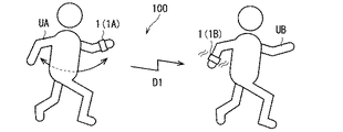
刺激処理部202は、受信した物理情報に基づいて、その物理量をユーザの皮膚の感覚器で再現するように、刺激部23にユーザの皮膚の感覚器を刺激させる。以下、図9を参照して、具体的な一例について説明する。図9は、装着型機器システム100の一例を概略的に示す図である。なお以下では、装着型機器1Aに属する構成要素については、その符号の末尾に「A」を付記し、装着型機器1Bに属する構成要素については、その符号の末尾に「B」を付記することがある。例えば制御部21Aは装着型機器1Aの制御部21を示し、刺激部23Bは装着型機器1Bの刺激部23を示す。   Based on the received physical information, the stimulation processing unit 202 causes the stimulation unit 23 to stimulate the sensory organ of the user's skin so that the physical quantity is reproduced by the sensory device of the user's skin. Hereinafter, a specific example will be described with reference to FIG. FIG. 9 is a diagram schematically illustrating an example of the wearable device system 100. In the following, for components belonging to the wearable device 1A, “A” is added to the end of the reference symbol, and for components belonging to the wearable device 1B, “B” is added to the end of the reference symbol. There is. For example, the control unit 21A indicates the control unit 21 of the wearable device 1A, and the stimulation unit 23B indicates the stimulation unit 23 of the wearable device 1B.

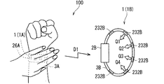
例えば図9に示すように、ユーザUAは、装着型機器1Aが装着されていない方の手を用いて装着型機器1Aを把持し、これを握りしめる。これにより、センサ26Aには力Fが印加される。センサ26Aはこの力Fを検出し、その検出結果を制御部21Aへと出力する。送受信処理部201Aは、例えばセンサ26Aの検出値を示す物理情報D1を、無線通信部22Aを介して装着型機器1Bへと送信する。   For example, as shown in FIG. 9, the user UA uses the hand on which the wearable device 1A is not worn to grip the wearable device 1A and grips it. Thereby, the force F is applied to the sensor 26A. The sensor 26A detects this force F and outputs the detection result to the control unit 21A. For example, the transmission / reception processing unit 201A transmits physical information D1 indicating the detection value of the sensor 26A to the wearable device 1B via the wireless communication unit 22A.

装着型機器1Bの送受信処理部201Bは、無線通信部22Bを介して物理情報D1を受信する。刺激処理部202Bは物理情報D1に基づいて締付機構231Bを制御する。より具体的には、刺激処理部202Bは、センサ26Aによって検出された力Fを締め付け力で再現すべく、締付機構231Bに、バンド部3Bを用いてユーザUBの体の一部(例えば腕)を締め付けさせる。   The transmission / reception processing unit 201B of the wearable device 1B receives the physical information D1 via the wireless communication unit 22B. The stimulus processing unit 202B controls the tightening mechanism 231B based on the physical information D1. More specifically, the stimulation processing unit 202B uses the band unit 3B for the tightening mechanism 231B to reproduce a force F detected by the sensor 26A with a tightening force. ).

刺激処理部202Bは、いわゆるフィードフォワード制御によってモータM1を制御してもよい。この場合、例えば力と電圧値との関係を予め記憶媒体213に記憶しておく。刺激処理部202Bは、力Fに対応する電圧値を、当該関係に基づいて決定し、当該電圧値をモータM1Bに印加してもよい。あるいは、刺激処理部202Bはフィードバック制御によってモータM1Bを制御してもよい。この場合、例えば、刺激処理部202Bは、センサ26Bによって検出される力と、力Fとの偏差を算出し、当該偏差が零に近づくように、当該偏差に基づいてモータM1Bを制御してもよい。これによれば、装着型機器1Bにおいて、より正確に力Fを再現することができる。   The stimulus processing unit 202B may control the motor M1 by so-called feedforward control. In this case, for example, the relationship between the force and the voltage value is stored in the storage medium 213 in advance. The stimulation processing unit 202B may determine a voltage value corresponding to the force F based on the relationship and apply the voltage value to the motor M1B. Alternatively, the stimulus processing unit 202B may control the motor M1B by feedback control. In this case, for example, the stimulus processing unit 202B calculates a deviation between the force detected by the sensor 26B and the force F, and controls the motor M1B based on the deviation so that the deviation approaches zero. Good. According to this, the force F can be more accurately reproduced in the wearable device 1B.

なおこの例では、物理量を再現する制御とは、当該物理量を目標値(或いは指令値)として用いた刺激部23の制御である、と捉えても構わない。   In this example, the control for reproducing the physical quantity may be regarded as the control of the stimulation unit 23 using the physical quantity as a target value (or command value).

以上のように、ユーザUAが腕を握りしめたときに、その力Fに応じた締め付け力で、ユーザUBの腕が締め付けられる。これにより、ユーザUBはユーザUAによる腕の握りしめを擬似的に体感することができる。例えばユーザUAが親であり、ユーザUBが子供である場合、親が自身の腕を子供の腕と想定して優しく握りしめることができる。その一方で、子供は親による腕の握りしめを擬似的に体感することができる。これにより、子供を安心させることができる。   As described above, when the user UA grips the arm, the arm of the user UB is tightened with a tightening force corresponding to the force F. Thereby, the user UB can experience a hand grip of the arm by the user UA in a pseudo manner. For example, when the user UA is a parent and the user UB is a child, the parent can gently grasp his / her arm by assuming his / her own arm. On the other hand, the child can experience a pseudo-hand grip of the arm by the parent. Thereby, a child can be relieved.

なお、送受信処理部201Aは、センサ26Aによって検出される物理量が所定の基準値よりも大きいときのみ、物理情報を送信してもよい。言い換えれば、物理量が小さすぎる場合には、送受信処理部201Aは、物理情報を装着型機器1Bへと送信しなくてもよい。これによれば、ノイズなどによって物理量がわずかに増大しても、その物理情報は送信されない。したがって、不要な送信を抑制することができる。   The transmission / reception processing unit 201A may transmit the physical information only when the physical quantity detected by the sensor 26A is larger than a predetermined reference value. In other words, if the physical quantity is too small, the transmission / reception processing unit 201A may not transmit physical information to the wearable device 1B. According to this, even if the physical quantity slightly increases due to noise or the like, the physical information is not transmitted. Therefore, unnecessary transmission can be suppressed.

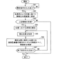
図10および図11は、それぞれ装着型機器1A,1Bの動作の一例を示すフローチャートである。図10および図11の一連の動作は、例えば所定時間ごとに繰り返し実行されてもよい。図10を参照して、ステップS1にて、センサ26Aは物理量(例えば力F)を検出し、その検出結果を制御部21Aへと出力する。次にステップS2にて、送受信処理部201Aは、センサ26Aによって検出された物理量が基準値よりも大きいか否かを判断する。この基準値は予め決められて記憶媒体に記憶されてもよく、例えば零に近い正の値であってよい。物理量が基準値よりも大きいと判断したときには、ステップS3にて、送受信処理部201Aは、物理量に基づく情報(物理情報)を、無線通信部22Aを介して、装着型機器1Bへと送信する。一方で、ステップS2において物理量が基準値よりも小さいと判断したときには、制御部21Aは処理を終了する。   10 and 11 are flowcharts showing examples of operations of the wearable devices 1A and 1B, respectively. The series of operations in FIGS. 10 and 11 may be repeatedly executed at predetermined time intervals, for example. Referring to FIG. 10, in step S1, sensor 26A detects a physical quantity (for example, force F) and outputs the detection result to control unit 21A. In step S2, the transmission / reception processing unit 201A determines whether the physical quantity detected by the sensor 26A is larger than a reference value. This reference value may be determined in advance and stored in the storage medium, and may be a positive value close to zero, for example. When it is determined that the physical quantity is larger than the reference value, in step S3, the transmission / reception processing unit 201A transmits information (physical information) based on the physical quantity to the wearable device 1B via the wireless communication unit 22A. On the other hand, when it is determined in step S2 that the physical quantity is smaller than the reference value, the control unit 21A ends the process.

なお、ステップS2は必ずしも必要ではない。送受信処理部201は、ステップS2の判断を行うことなく、物理量に基づく物理情報を送信してもよい。この点は、後述する他のフローチャートでも同様である。   Step S2 is not always necessary. The transmission / reception processing unit 201 may transmit physical information based on the physical quantity without performing the determination in step S2. This also applies to other flowcharts described later.

図11を参照して、ステップS11にて、装着型機器1Bの送受信処理部201Bは、物理量に基づく情報(物理情報)を、無線通信部22Bを介して受信したか否かを判断する。物理情報を受信していないと判断したときには、送受信処理部201Bは再びステップS11を実行する。物理情報を受信したと判断したときには、ステップS12にて、刺激処理部202Bは、物理量をユーザの皮膚の感覚器で再現すべく、当該物理情報に基づいて、刺激部23Bにユーザの感覚器を刺激させる。例えば刺激処理部202Bは上述のようにモータM1Bを物理情報に基づいて制御して、バンド部3Bを用いてユーザUBの腕を締め付ける。   Referring to FIG. 11, in step S11, transmission / reception processing unit 201B of wearable device 1B determines whether information (physical information) based on a physical quantity has been received via wireless communication unit 22B. When determining that the physical information has not been received, the transmission / reception processing unit 201B executes step S11 again. When it is determined that the physical information has been received, in step S12, the stimulus processing unit 202B places the user's sensory device on the stimulus unit 23B based on the physical information in order to reproduce the physical quantity with the sensory device of the user's skin. Stimulate. For example, the stimulation processing unit 202B controls the motor M1B based on the physical information as described above, and tightens the arm of the user UB using the band unit 3B.

なお、上述の例では、装着型機器1Aから装着型機器1Bへと物理情報を送信しているものの、その逆に、装着型機器1Bが装着型機器1Aへと物理情報を送信してもよい。つまり、装着型機器1Bがセンサ26Bによって検出された物理量に基づく情報を、装着型機器1Aへと送信し、装着型機器1Aがその物理情報に基づいてユーザUAの腕を締め付けてもよい。これによれば、ユーザUBは自身の腕をユーザUAの腕と想定して握りしめることができ、ユーザUAはユーザUBによる握りしめを擬似的に体感することができる。言い換えれば、図10の動作を装着型機器1Bが行い、図11の動作を装着型機器1Aが行ってもよい。この点は、後述する他のフローチャートでも同様である。   In the above-described example, physical information is transmitted from the wearable device 1A to the wearable device 1B. Conversely, the wearable device 1B may transmit physical information to the wearable device 1A. . That is, the wearable device 1B may transmit information based on the physical quantity detected by the sensor 26B to the wearable device 1A, and the wearable device 1A may tighten the arm of the user UA based on the physical information. According to this, it is possible for the user UB to grasp his / her own arm as the user's UA's arm, and the user UA can experience the hand grip by the user UB in a pseudo manner. In other words, the wearable device 1B may perform the operation of FIG. 10, and the wearable device 1A may perform the operation of FIG. This also applies to other flowcharts described later.

またこの装着型機器1によれば、ユーザによる腕の握りしめを、ユーザ間の合図として用いることもできる。例えば1回の握りしめを、「こんにちは」などの挨拶の合図として用いることができる。これによって、ユーザUA,UBは装着型機器1を用いて意思疎通を図ることができる。このような意思疎通は、ユーザUA,UBによる会話を必要としないので、例えばユーザUA,UBが水中に居る場合に特に有効である。また、装着型機器1を用いた意思疎通によれば、伝えたい内容が他の人にばれにくい。よって、集団の中において、ユーザは他の人に秘匿しながら、特定のユーザに意図を伝えることができる。また、装着型機器1を用いた意思疎通は、例えばジェスチャーによる意思疎通(例えば手話)とは異なって、ユーザUA,UBの相互視認を必要としない。よって、ユーザUA,UBが相互に視認できない状態であっても、意思疎通を図ることができる。   Further, according to the wearable device 1, the arm gripping by the user can be used as a cue between the users. For example, a clenched once, it can be used as a sign of greeting such as "Hello". As a result, the users UA and UB can communicate with each other using the wearable device 1. Such communication does not require a conversation by the users UA and UB, and is particularly effective when the users UA and UB are underwater, for example. Further, according to the communication using the wearable device 1, it is difficult for the content to be transmitted to other people. Therefore, in the group, the user can convey the intention to a specific user while keeping it secret from other people. Further, communication using the wearable device 1 does not require mutual visual recognition between the users UA and UB, for example, unlike communication using gestures (for example, sign language). Therefore, even when the users UA and UB cannot see each other, communication can be achieved.

なお合図は、例えば握りしめパターンによって表現されてもよい。例えばこのパターンは、握りしめの回数、握りしめが維持される時間、握りしめの時間間隔、および、握る力の少なくともいずれか一つによって表現される。   The cue may be expressed by a clenching pattern, for example. For example, this pattern is expressed by at least one of the number of times of clasping, the time for which the clashes are maintained, the time interval of the clasping, and the gripping force.

また、上述の制御によれば、例えば装着型機器1Aが物にぶつかって衝撃を受けたときには、その衝撃の力が装着型機器1BによってユーザUBの皮膚の感覚器で再現される。したがって、ユーザUBは、ユーザUAの腕と物の衝突も擬似的に体感することができる。   Further, according to the above-described control, for example, when the wearable device 1A hits an object and receives an impact, the impact force is reproduced by the wearable device 1B on the skin sensation device of the user UB. Therefore, the user UB can also experience the collision between the arm and the object of the user UA in a pseudo manner.

<物理量に基づく情報>
上述の例では、物理量に基づく物理情報の具体例として、センサ26によって検出された物理量の値を示す情報を採用した。しかるに、例えば締付機構231がモータM1を備えている場合、装着型機器1は、物理量に基づく物理情報として、例えば、センサ26によって検出される物理量を再現するためにモータM1に印加すべき電圧値を、採用してもよい。そして、刺激処理部202は、受信した電圧値に基づいてモータM1を制御してもよい。要するに、装着型機器1は、物理量を再現するための刺激部23の制御に必要な情報を、物理量に基づく物理情報として送信すればよい。
<Information based on physical quantities>
In the above-described example, information indicating the value of the physical quantity detected by the sensor 26 is employed as a specific example of the physical information based on the physical quantity. However, for example, when the tightening mechanism 231 includes the motor M1, the wearable device 1 uses, as physical information based on the physical quantity, for example, a voltage to be applied to the motor M1 in order to reproduce the physical quantity detected by the sensor 26. A value may be adopted. Then, the stimulus processing unit 202 may control the motor M1 based on the received voltage value. In short, the wearable device 1 may transmit information necessary for controlling the stimulation unit 23 for reproducing the physical quantity as physical information based on the physical quantity.

<物理量に基づく物理情報の送信態様>
図10の動作を繰り返すことにより、装着型機器1は、基準値よりも大きな物理量を検出する度に、その物理量に基づく物理情報を送信できる。しかるに、装着型機器1は必ずしも検出の度に物理情報を送信する必要はない。例えば装着型機器1は、複数回にわたって物理量を検出したときに、その複数の物理量をまとめた物理情報(例えば物理量の時系列データ)を送信してもよい。装着型機器1Bは、この物理情報に基づいて、物理量をユーザの皮膚の感覚器で再現すべく、ユーザの皮膚の感覚器を刺激してもよい。これによれば、物理情報の送信回数を低減することができる。
<Transmission mode of physical information based on physical quantity>
By repeating the operation in FIG. 10, the wearable device 1 can transmit physical information based on the physical quantity each time a physical quantity larger than the reference value is detected. However, the wearable device 1 does not necessarily need to transmit physical information each time it is detected. For example, when the wearable device 1 detects a physical quantity a plurality of times, the wearable device 1 may transmit physical information (for example, time-series data of the physical quantity) that summarizes the plurality of physical quantities. The wearable device 1B may stimulate the sensory organs of the user's skin to reproduce the physical quantity with the sensory organs of the user's skin based on the physical information. According to this, the number of physical information transmissions can be reduced.

<送信先の指定>
装着型機器1は2以上の別の装着型機器1と通信可能であってもよい。この場合、入力部24は、送信先を指定するための入力を受け付けてもよい。例えば記憶媒体213には、複数の別の装着型機器1にそれぞれ割り当てられた複数の宛先情報が記憶されている。入力部24は、この複数の宛先情報の一つを指定するための入力を受け付けてもよい。以下に、具体的な処理の一例を説明する。
<Specifying the destination>
The wearable device 1 may be able to communicate with two or more other wearable devices 1. In this case, the input unit 24 may accept an input for designating a transmission destination. For example, the storage medium 213 stores a plurality of pieces of destination information respectively assigned to a plurality of other wearable devices 1. The input unit 24 may accept an input for designating one of the plurality of pieces of destination information. Hereinafter, an example of specific processing will be described.

制御部21は、記憶媒体213から複数の宛先情報を読み出し、これらの情報を表示部25に一覧で表示させる。なお、制御部21は宛先情報に替えて、或いは、宛先情報とともに、その宛先情報で示される装着型機器1のユーザ情報(例えばユーザの名前)を表示してもよい。このユーザ情報は、例えば、宛先情報に対応付けられて記憶媒体213に記憶されていてもよい。このようにユーザ情報が表示される場合には、ユーザは送信先を選択しやすい。   The control unit 21 reads a plurality of pieces of destination information from the storage medium 213 and causes the display unit 25 to display these information in a list. The control unit 21 may display the user information (for example, the name of the user) of the wearable device 1 indicated by the destination information instead of the destination information or together with the destination information. For example, this user information may be stored in the storage medium 213 in association with the destination information. When user information is displayed in this way, the user can easily select a transmission destination.

ユーザは、表示領域251を見て複数の宛先情報を確認しつつ、入力部24を用いて、そのうちの一つを指定する。例えば入力部24がタッチパネルである場合、ユーザは、表示領域251において宛先情報(あるいはユーザ情報)が表示された部分を、操作子(例えば指)で操作する。入力部24は当該操作を検出して、その情報を制御部21へと出力する。制御部21(送受信処理部201)はこの情報に基づいて、操作された宛先情報を送信先に設定する。そして、送受信処理部201は、センサ26によって検出された物理量に基づく情報を、設定された送信先へと送信する。   The user looks at the display area 251 and confirms a plurality of pieces of destination information, and designates one of them using the input unit 24. For example, when the input unit 24 is a touch panel, the user operates a portion where the destination information (or user information) is displayed in the display area 251 with an operator (for example, a finger). The input unit 24 detects the operation and outputs the information to the control unit 21. Based on this information, the control unit 21 (transmission / reception processing unit 201) sets the operated destination information as a transmission destination. Then, the transmission / reception processing unit 201 transmits information based on the physical quantity detected by the sensor 26 to the set transmission destination.

<複数の送信先の指定>
入力部24は、複数の送信先を指定するための入力を受け付けてもよい。制御部21は当該入力に応答して、複数の宛先情報を送信先に設定する。そして、送受信処理部201は、センサ26によって検出された物理量に基づく情報を、設定された複数の装着型機器1へと送信する。
<Specifying multiple destinations>
The input unit 24 may accept input for designating a plurality of transmission destinations. In response to the input, the control unit 21 sets a plurality of pieces of destination information as transmission destinations. Then, the transmission / reception processing unit 201 transmits information based on the physical quantity detected by the sensor 26 to the plurality of set wearable devices 1.

これによれば、例えば、ユーザが装着型機器1を握りしめることにより、他の複数のユーザの腕がそれぞれの装着型機器1によって締め付けられる。したがって、例えば親が複数の子供に対して擬似的に腕を握りしめることができる。逆に言えば、複数の子供が親の握りしめを擬似的に体感できる。   According to this, for example, when the user grips the wearable device 1, the arms of a plurality of other users are tightened by the respective wearable devices 1. Therefore, for example, a parent can artificially grasp an arm against a plurality of children. In other words, a plurality of children can experience the clenching of their parents in a pseudo manner.

あるいは、ユーザは他の複数のユーザに対して合図を送ることができる。例えば複数のユーザ(例えば家族)の間で、ある握りしめのパターンを、所定の集合場所で集合するための合図に決めておく。そして、一人のユーザがそのパターンで装着型機器1を握りしめることにより、他の全てのユーザにその合図を伝えることができる。合図を受けたユーザは集合場所に移動することで、全てのユーザが集合する。   Alternatively, the user can send a signal to other users. For example, a grip pattern is determined as a signal for gathering at a predetermined gathering place among a plurality of users (for example, family members). Then, when one user grips the wearable device 1 in the pattern, the signal can be transmitted to all other users. When the user who receives the signal moves to the meeting place, all the users gather.

<温度>
<温度変化の再現>
図12は、装着型機器1の電気的構成の一例を概略的に示す機能ブロック図である。図12の装着型機器1は、刺激部23およびセンサ26という点で、図3の装着型機器1と相違する。
<Temperature>
<Reproduction of temperature change>
FIG. 12 is a functional block diagram schematically illustrating an example of the electrical configuration of the wearable device 1. The wearable device 1 in FIG. 12 is different from the wearable device 1 in FIG. 3 in that the stimulation unit 23 and the sensor 26 are used.

図12の例示では、センサ26は、例えば物理量として温度を検出する温度センサである。温度センサは、例えば温度検出用の温度抵抗を有していてもよい。この温度抵抗の抵抗値は、温度に依存して変化する。よって、制御部21は温度抵抗の温度を、温度抵抗の電圧および電流に基づいて検出することができる。言い換えれば、センサ26は温度を電気信号に変換し、この電気信号を制御部21に出力することができる。これにより、制御部21はこの電気信号に基づいて温度を認識することができる。   In the illustration of FIG. 12, the sensor 26 is a temperature sensor that detects a temperature as a physical quantity, for example. The temperature sensor may have a temperature resistance for temperature detection, for example. The resistance value of this temperature resistance changes depending on the temperature. Therefore, the control unit 21 can detect the temperature of the temperature resistance based on the voltage and current of the temperature resistance. In other words, the sensor 26 can convert the temperature into an electrical signal and output the electrical signal to the control unit 21. Thereby, the control part 21 can recognize temperature based on this electrical signal.

このセンサ26は本体部2またはバンド部3に設けられており、ユーザの体温を検出することができる。なお、センサ26はユーザの皮膚に接触して、直接に体温を検出してもよい。あるいは、センサ26が本体部2またはバンド部3を介してユーザからの熱を受け取ってもよい。つまり、センサ26は間接的にユーザの体温を検出してもよい。   The sensor 26 is provided in the main body 2 or the band unit 3 and can detect a user's body temperature. The sensor 26 may directly detect the body temperature by contacting the user's skin. Alternatively, the sensor 26 may receive heat from the user via the main body unit 2 or the band unit 3. That is, the sensor 26 may indirectly detect the user's body temperature.

送受信処理部201は、センサ26によって検出された温度に基づく物理情報を、無線通信部22を介して別の装着型機器1へと送信する。また送受信処理部201は、温度に基づく物理情報を別の装着型機器1から無線通信部22を介して受信する。ここでいう温度に基づく物理情報とは、例えば温度自体を示す情報であってもよい。   The transmission / reception processing unit 201 transmits physical information based on the temperature detected by the sensor 26 to another wearable device 1 via the wireless communication unit 22. The transmission / reception processing unit 201 receives physical information based on temperature from another wearable device 1 via the wireless communication unit 22. The physical information based on temperature here may be information indicating the temperature itself, for example.

刺激部23は例えば冷熱素子232を有していてもよい。冷熱素子232は制御部21によって制御される。冷熱素子232は可制御の熱を発生または吸収する。これにより、冷熱素子232は可制御の熱をユーザの装着部位(例えば腕)と交換することができる。つまり、冷熱素子232は制御部21の制御の下で、ユーザの装着部位を温めたり、或いは、ユーザの装着部位を冷やすことができる。換言すれば、冷熱素子232は、可制御の刺激量でユーザの皮膚の温度覚の受容器を刺激することができる。   The stimulation unit 23 may have a cooling element 232, for example. The cooling element 232 is controlled by the control unit 21. The cold element 232 generates or absorbs controllable heat. Thereby, the cooling element 232 can exchange controllable heat with a user's wearing part (for example, arm). That is, the cooling / heating element 232 can warm the user's wearing site or cool the user's wearing site under the control of the control unit 21. In other words, the thermal element 232 can stimulate a temperature sensation receptor on the user's skin with a controllable stimulus amount.

冷熱素子232は例えばヒータまたはペルチェ素子である。ヒータは熱を発生させることができ、ペルチェ素子は熱を発生させたり、あるいは、熱を吸収することができる。例えばヒータは電熱線を有しており、刺激処理部202は、この電熱線に流す電流を制御することで、ヒータの発熱量を制御することができる。例えば電池27と電熱線との間にDC(Direct Current)/DCコンバータを接続し、刺激処理部202がこのDC/DCコンバータを制御することで、電熱線に流れる電流の大きさを制御してもよい。電熱線に流れる電流が大きいほど、発熱量は大きい。   The cooling element 232 is, for example, a heater or a Peltier element. The heater can generate heat, and the Peltier element can generate heat or absorb heat. For example, the heater has a heating wire, and the stimulation processing unit 202 can control the amount of heat generated by the heater by controlling the current flowing through the heating wire. For example, a direct current (DC) / DC converter is connected between the battery 27 and the heating wire, and the stimulation processing unit 202 controls the DC / DC converter, thereby controlling the magnitude of the current flowing through the heating wire. Also good. The greater the current flowing through the heating wire, the greater the amount of heat generated.

ペルチェ素子は、例えば、第1から第3の金属板と、第1および第2の半導体とを備えている。第1の半導体は例えばP型の半導体であって、第1の金属板と第2の金属板との間に接続されている。第2の半導体は例えばN型の半導体であって、第2の金属板と第3の金属板との間に接続されている。このようなペルチェ素子において、第1の金属板から第3の金属板に向かって電流を流すと、ペルチェ効果により、第1の金属板が熱を放出し、第2の金属板が熱を吸収する。反対方向に電流を流すと、ペルチェ効果により、第2の金属板が熱を放出し、第3の金属板が熱を吸収する。   The Peltier element includes, for example, first to third metal plates and first and second semiconductors. The first semiconductor is, for example, a P-type semiconductor, and is connected between the first metal plate and the second metal plate. The second semiconductor is, for example, an N-type semiconductor, and is connected between the second metal plate and the third metal plate. In such a Peltier element, when a current is passed from the first metal plate to the third metal plate, the first metal plate releases heat and the second metal plate absorbs heat due to the Peltier effect. To do. When a current is passed in the opposite direction, the second metal plate releases heat and the third metal plate absorbs heat due to the Peltier effect.

例えば、このペルチェ素子は、第2の金属板をユーザの腕側(つまり装着型機器1の内周側)に向けつつ、第1および第3の金属板をユーザの腕とは反対側(つまり外周側)に向けて、配置されてもよい。刺激処理部202は、第1の金属板と第3の金属板との間の直流電圧の向きを制御することで、第2の金属板側において熱を発生させたり、あるいは、熱を吸収したりできる。言い換えれば、ペルチェ素子は、ユーザの腕に熱を与えたり、あるいは、ユーザの腕から熱を吸収することができる。   For example, the Peltier element has the first and third metal plates opposite to the user's arm (that is, the second metal plate is directed to the user's arm side (that is, the inner peripheral side of the wearable device 1). You may arrange | position toward the outer peripheral side. The stimulus processing unit 202 generates heat on the second metal plate side or absorbs heat by controlling the direction of the DC voltage between the first metal plate and the third metal plate. You can. In other words, the Peltier element can apply heat to the user's arm or absorb heat from the user's arm.

例えば電池27の高電位出力端および低電位出力端と、第1および第3の金属板との接続関係を切り替えるスイッチを設け、刺激処理部202が当該スイッチを制御することで、直流電圧の向きを制御してもよい。また、刺激処理部202は当該直流電圧の大きさを制御することでその熱量を制御できる。例えば電池27とペルチェ素子との間に、DC/DCコンバータを接続し、刺激処理部202がこのDC/DCコンバータを制御することで、当該直流電圧を制御してもよい。   For example, a switch for switching the connection relationship between the high potential output terminal and the low potential output terminal of the battery 27 and the first and third metal plates is provided, and the stimulation processing unit 202 controls the switch so that the direction of the DC voltage is controlled. May be controlled. Further, the stimulus processing unit 202 can control the amount of heat by controlling the magnitude of the DC voltage. For example, a DC / DC converter may be connected between the battery 27 and the Peltier element, and the DC voltage may be controlled by the stimulation processing unit 202 controlling the DC / DC converter.

刺激処理部202は、別の装着型機器1から受信した物理情報に基づいて、その温度の変化を再現すべく、冷熱素子232を制御する。   Based on the physical information received from another wearable device 1, the stimulus processing unit 202 controls the cooling element 232 to reproduce the change in temperature.

例えば装着型機器1Aのセンサ26AはユーザUAの体温を繰り返し検出する。送受信処理部201Aは、例えば、この温度の変化を示す情報を、温度に基づく物理情報として装着型機器1Bへと送信する。この温度の変化とは、例えばユーザの平温からの変化であってもよい。例えば、この平温はセンサ26Aによって検出されてもよい。より具体的には、例えば入力部24Aは、平温を検出するための入力を受け付けてもよい。制御部21Aは、この入力に応答して、センサ26Aによって検出された温度を、平温として記憶媒体213に記憶する。そして、制御部21Aは、平温を検出したタイミングとは別のタイミングで検出された温度と、平温との温度差を算出し、その温度差を示す情報を、温度の変化を示す情報として送信してもよい。   For example, the sensor 26A of the wearable device 1A repeatedly detects the body temperature of the user UA. For example, the transmission / reception processing unit 201A transmits information indicating the change in temperature to the wearable device 1B as physical information based on the temperature. This change in temperature may be, for example, a change from the normal temperature of the user. For example, this normal temperature may be detected by the sensor 26A. More specifically, for example, the input unit 24A may accept an input for detecting a normal temperature. In response to this input, the control unit 21A stores the temperature detected by the sensor 26A in the storage medium 213 as a normal temperature. Then, the control unit 21A calculates a temperature difference between the temperature detected at a timing different from the timing at which the normal temperature is detected and the normal temperature, and information indicating the temperature difference is used as information indicating a change in temperature. You may send it.

装着型機器1Bの送受信処理部201Bは温度に基づく物理情報を受信する。そして、刺激処理部202Bは、この温度の変化をユーザの皮膚の感覚器で再現すべく、物理情報に基づいて冷熱素子232を制御する。例えば、温度が上昇しているときには、その上昇量に対応する熱を、冷熱素子232Bに発生させる。   The transmission / reception processing unit 201B of the wearable device 1B receives physical information based on temperature. Then, the stimulation processing unit 202B controls the cooling element 232 based on the physical information so as to reproduce the change in temperature with the sensory organ of the user's skin. For example, when the temperature is rising, heat corresponding to the rising amount is generated in the cooling element 232B.

刺激処理部202Bは例えばフィードフォワード制御を行ってもよい。例えば、温度差と電流との関係を予め記憶媒体213に記憶しておく。刺激処理部202Bは、装着型機器1Aから受信した物理情報に基づいて、ユーザUAの温度差を把握し、この温度差と上記関係とに基づいて決定される電流を、ヒータまたはペルチェ素子に流してもよい。あるいは、刺激処理部202Bは例えばフィードバック制御を行ってもよい。例えば装着型機器1Bの記憶媒体213に、ユーザUBの平温を記憶しておく。このユーザUBの平温はユーザUAの平温と同様の手法によって、記憶媒体213に記憶されてもよい。刺激処理部202Bは、センサ26Bによって検出される温度と、ユーザUBの平温との温度差を算出し、次に、ユーザUBの温度差と、ユーザUAの温度差との偏差を算出する。そして、刺激処理部202Bは、この偏差が零に近づくように、当該偏差に基づいてヒータまたはペルチェ素子の熱量を制御してもよい。これによれば、より高い精度で、ユーザUAの体温上昇量でユーザUBの腕を温めることができる。   The stimulus processing unit 202B may perform feed forward control, for example. For example, the relationship between the temperature difference and the current is stored in the storage medium 213 in advance. The stimulus processing unit 202B grasps the temperature difference of the user UA based on the physical information received from the wearable device 1A, and sends a current determined based on the temperature difference and the above relationship to the heater or the Peltier element. May be. Alternatively, the stimulus processing unit 202B may perform feedback control, for example. For example, the normal temperature of the user UB is stored in the storage medium 213 of the wearable device 1B. This normal temperature of the user UB may be stored in the storage medium 213 by the same method as the normal temperature of the user UA. The stimulus processing unit 202B calculates a temperature difference between the temperature detected by the sensor 26B and the normal temperature of the user UB, and then calculates a deviation between the temperature difference of the user UB and the temperature difference of the user UA. Then, the stimulation processing unit 202B may control the amount of heat of the heater or the Peltier element based on the deviation so that the deviation approaches zero. According to this, the arm of the user UB can be warmed with a higher amount of body temperature of the user UA with higher accuracy.

以上のように、ユーザUAの体温上昇に伴って、ユーザUBの腕が温められるので、ユーザUBはユーザUAの体温上昇を擬似的に体感することができる。   As described above, as the user UA's body temperature rises, the user's UB's arm is warmed, so the user UB can experience the user UA's body temperature rise in a pseudo manner.

冷熱素子232Bがペルチェ素子である場合には、ユーザから熱を吸収することができる。よって、装着型機器1Bは例えばユーザUAの体温の低下も再現できる。この温度の低下に基づく物理情報は、装着型機器1Aから装着型機器1Bへと送信される。刺激処理部202Bは、この物理情報に基づいて、その低下量に対応する熱を冷熱素子232Bに吸収させる。具体的な制御の一例は上述と同様である。これにより、ユーザUAの体温低下に伴ってユーザUBの腕が冷やされる。よって、ユーザUBはユーザUAの体温低下を擬似的に体感することができる。   When the cooling / heating element 232B is a Peltier element, heat can be absorbed from the user. Therefore, the wearable device 1B can reproduce, for example, a decrease in the body temperature of the user UA. The physical information based on the decrease in temperature is transmitted from the wearable device 1A to the wearable device 1B. Based on this physical information, the stimulus processing unit 202B causes the cooling element 232B to absorb heat corresponding to the amount of decrease. An example of specific control is the same as described above. Thereby, a user's UB arm is cooled with the fall of the user's UA body temperature. Therefore, the user UB can experience the user UA's body temperature fall in a pseudo manner.

以上のように、ユーザUBはユーザUAの体温の変化を体感できる。よって、ユーザUBはユーザUAの体温の変化に応じた処理を行うことができる。例えば、ユーザUAが子供であり、ユーザUBが親である場合に、親が子供を迎えに行って、適切な処理を施すことができる。   As described above, the user UB can experience a change in the body temperature of the user UA. Therefore, the user UB can perform processing according to the change in the body temperature of the user UA. For example, when the user UA is a child and the user UB is a parent, the parent can pick up the child and perform appropriate processing.

しかも、装着型機器1によれば、ユーザUBは、ユーザUAの体温の変化の情報を例えば数字で知るのではなく、実際の体温の変化を擬似的に体感することができる。したがって、ユーザUBはユーザUAの状態を共感しやすい。よって、体温の変化が急激に生じた場合には、ユーザUBはその緊急性を実感しやすい。   Moreover, according to the wearable device 1, the user UB can not only know the information on the change in the body temperature of the user UA, for example, by numbers, but can experience the actual change in the body temperature in a pseudo manner. Therefore, the user UB tends to sympathize with the state of the user UA. Therefore, when the body temperature changes suddenly, the user UB can easily feel the urgency.

図13および図14は、それぞれ装着型機器1A,1Bの動作の一例を示すフローチャートである。図13および図14の一連の動作は、例えば所定時間ごとに繰り返し実行されてもよい。図13を参照して、ステップS21にて、センサ26Aは温度を検出し、その検出結果を制御部21Aへと出力する。次にステップS22にて、送受信処理部201Aは、センサ26Aによって検出された温度と、記憶媒体213に記憶された平温との温度差が温度差基準値よりも大きいか否かを判断する。この温度差基準値は予め決められて記憶媒体213に記憶されてもよく、例えば零に近い正の値であってよい。当該温度差が温度差基準値よりも大きいと判断したときには、ステップS23にて、送受信処理部201Aは、温度に基づく物理情報(例えば当該温度差を示す情報)を、無線通信部22Aを介して、装着型機器1Bへと送信する。一方で、ステップS22において当該温度差が温度差基準値よりも小さいと判断したときには、制御部21Aは処理を終了する。   13 and 14 are flowcharts showing examples of operations of the wearable devices 1A and 1B, respectively. The series of operations in FIGS. 13 and 14 may be repeatedly executed at predetermined time intervals, for example. Referring to FIG. 13, in step S21, sensor 26A detects the temperature, and outputs the detection result to control unit 21A. Next, in step S22, the transmission / reception processing unit 201A determines whether or not the temperature difference between the temperature detected by the sensor 26A and the normal temperature stored in the storage medium 213 is greater than the temperature difference reference value. This temperature difference reference value may be determined in advance and stored in the storage medium 213, and may be a positive value close to zero, for example. When it is determined that the temperature difference is larger than the temperature difference reference value, in step S23, the transmission / reception processing unit 201A sends temperature-based physical information (for example, information indicating the temperature difference) via the wireless communication unit 22A. To the wearable device 1B. On the other hand, when it is determined in step S22 that the temperature difference is smaller than the temperature difference reference value, the control unit 21A ends the process.

なお制御部21はステップS22を実行せずにステップS23を実行してもよい。ただし、ステップS22によれば、ノイズなどによって温度が増大または低減しても、その温度に基づく物理情報は送信されない。したがって、不要な送信を抑制することができる。   Note that the control unit 21 may execute step S23 without executing step S22. However, according to step S22, even if the temperature increases or decreases due to noise or the like, physical information based on the temperature is not transmitted. Therefore, unnecessary transmission can be suppressed.

図14を参照して、ステップS31にて、送受信処理部201Bは、温度に基づく物理情報を、無線通信部22Bを介して受信したか否かを判断する。物理情報を受信していないと判断したときには、送受信処理部201Bは再びステップS31を実行する。物理情報を受信したと判断したときには、ステップS32にて、刺激処理部202Bは温度の変化を再現すべく、上述のように、当該物理情報に基づいて冷熱素子232を制御する。   Referring to FIG. 14, in step S31, transmission / reception processing unit 201B determines whether or not physical information based on temperature has been received via wireless communication unit 22B. When determining that physical information has not been received, the transmission / reception processing unit 201B executes step S31 again. When it is determined that physical information has been received, in step S32, the stimulus processing unit 202B controls the cooling element 232 based on the physical information as described above in order to reproduce the temperature change.

<温度の再現>
上述の例では、装着型機器1Bが、装着型機器1Aのセンサ26Aによって検出された温度と平温との温度差を再現した。しかるに、装着型機器1Bは、センサ26Aによって検出された温度自体を再現してもよい。即ち、刺激処理部202Bは、センサ26Aによって検出された温度を再現すべく、冷熱素子232BにユーザUBの装着部位と熱を交換させてもよい。例えば、刺激処理部202Bは、センサ26Bによって検出される温度が、装着型機器1Aのセンサ26Aによって検出された温度とほぼ一致するように、冷熱素子232Bを制御してもよい。これによれば、ユーザUBはユーザUAの体温を擬似的に体感することができる。
<Reproduction of temperature>
In the above-described example, the wearable device 1B reproduces the temperature difference between the temperature detected by the sensor 26A of the wearable device 1A and the normal temperature. However, the wearable device 1B may reproduce the temperature itself detected by the sensor 26A. In other words, the stimulation processing unit 202B may cause the cooling / heating element 232B to exchange heat with the wearing part of the user UB in order to reproduce the temperature detected by the sensor 26A. For example, the stimulus processing unit 202B may control the cooling / heating element 232B so that the temperature detected by the sensor 26B substantially matches the temperature detected by the sensor 26A of the wearable device 1A. According to this, the user UB can experience the body temperature of the user UA in a pseudo manner.

<温度分布の再現>
図15は、装着型機器1の構成の一例を概略的に示す図である。図15に例示するように、冷熱素子232は複数設けられてもよい。これら複数の冷熱素子232は例えばバンド部3の周方向に沿って並んで設けられていてもよい。例えばバンド部3にフレキシブルプリント基板を設け、この基板上に、複数の冷熱素子232(例えば電熱線またはペルチェ素子)を設けてもよい。制御部21は複数の冷熱素子232と個別に接続されており、冷熱素子232の熱量を個別に制御することができる。
<Reproduction of temperature distribution>
FIG. 15 is a diagram schematically illustrating an example of the configuration of the wearable device 1. As illustrated in FIG. 15, a plurality of cooling elements 232 may be provided. The plurality of cooling elements 232 may be provided side by side along the circumferential direction of the band portion 3, for example. For example, a flexible printed circuit board may be provided in the band unit 3, and a plurality of cooling / heating elements 232 (for example, heating wires or Peltier elements) may be provided on the board. The control unit 21 is individually connected to the plurality of cooling elements 232 and can individually control the amount of heat of the cooling elements 232.

またセンサ26も複数設けられてもよい。これらのセンサ26もバンド部3の周方向に沿って並んで設けられてもよい。またセンサ26は上述の基板上に設けられてもよい。複数のセンサ26は、互いに異なる複数の位置において温度を検出する。言い換えれば、センサ26は、物理量として、複数の位置における温度を検出する。   A plurality of sensors 26 may also be provided. These sensors 26 may also be provided side by side along the circumferential direction of the band portion 3. The sensor 26 may be provided on the above-described substrate. The plurality of sensors 26 detect temperatures at a plurality of different positions. In other words, the sensor 26 detects temperatures at a plurality of positions as physical quantities.

センサ26の個数と冷熱素子232の個数とは互いに等しくてもよい。またこの場合、センサ26の各々の周方向における位置が、冷熱素子232の各々の周方向における位置と同じであってもよい。より具体的には、センサ26の一部の周方向の位置が、冷熱素子232の一部の周方向の位置と同じであってもよい。   The number of sensors 26 and the number of cooling elements 232 may be equal to each other. In this case, the position of each of the sensors 26 in the circumferential direction may be the same as the position of each of the cooling / heating elements 232 in the circumferential direction. More specifically, a partial circumferential position of the sensor 26 may be the same as a partial circumferential position of the cooling / heating element 232.

送受信処理部201Aは、複数のセンサ26Aによって検出された温度に基づく物理情報を装着型機器1Bへと送信してもよい。装着型機器1Bの送受信処理部201Bはこの物理情報を受信する。そして、刺激処理部202Bは、装着型機器1Aの温度分布をユーザUBの皮膚の感覚器で再現すべく、物理情報に基づいて複数の冷熱素子232を制御してもよい。   The transmission / reception processing unit 201A may transmit physical information based on the temperatures detected by the plurality of sensors 26A to the wearable device 1B. The transmission / reception processing unit 201B of the wearable device 1B receives this physical information. Then, the stimulation processing unit 202B may control the plurality of cooling elements 232 based on physical information in order to reproduce the temperature distribution of the wearable device 1A with the skin sensation device of the user UB.

例えば、刺激処理部202Bは、各センサ26Bによって検出される温度が、対応するセンサ26Aによって検出された温度に近づくように、冷熱素子232Bの熱量を個別に制御する。これによれば、装着型機器1Aの温度分布が、装着型機器1Bにおいて再現される。   For example, the stimulus processing unit 202B individually controls the amount of heat of the cooling element 232B so that the temperature detected by each sensor 26B approaches the temperature detected by the corresponding sensor 26A. According to this, the temperature distribution of the wearable device 1A is reproduced in the wearable device 1B.

図16は、装着型機器システム100の構成の一例を示す図である。例えば図16に示すように、ユーザUAは、装着型機器1Aを装着していない方の手のひらでバンド部3の一部を覆って、このバンド部3の一部を温める。これにより、バンド部3のうち手に覆われた部分に設けられた複数のセンサ26Aの検出温度が上昇する。図16に例示する装着型機器1においては、4つのセンサ26Aが手のひらで覆われることになるので、この4つのセンサ26Aによって検出される温度が上昇する。なお、ここでは一例として、6個のセンサ26Aが周方向に沿って並んで設けられており、そのうち、両端のセンサ26Aを除く4つのセンサ26Aが手のひらで覆われていると仮定する。   FIG. 16 is a diagram illustrating an example of the configuration of the wearable device system 100. For example, as shown in FIG. 16, the user UA covers a part of the band unit 3 with the palm of the hand not wearing the wearable device 1A and warms a part of the band unit 3. As a result, the detected temperatures of the plurality of sensors 26 </ b> A provided in the portion of the band unit 3 that is covered with the hand rise. In the wearable device 1 illustrated in FIG. 16, the four sensors 26 </ b> A are covered with the palm, and the temperature detected by the four sensors 26 </ b> A increases. Here, as an example, it is assumed that six sensors 26A are provided side by side along the circumferential direction, and four sensors 26A excluding the sensors 26A at both ends are covered with palms.

装着型機器1Aの送受信処理部201Aは、全てのセンサ26Aによって検出される温度に基づく物理情報D1を、装着型機器1Bへと送信する。物理情報D1には、例えば全てのセンサ26Aによる検出温度が含まれている。装着型機器1Bの送受信処理部201Bは物理情報D1を受信し、刺激処理部202Bがこの物理情報D1に基づいて複数の冷熱素子232を個別に制御する。図16の例示では、冷熱素子232は、センサ26と同じく6個設けられている。刺激処理部202Bは物理情報D1に基づいて、センサ26Aに対応する位置に設けられた冷熱素子232Bを個別に制御する。   The transmission / reception processing unit 201A of the wearable device 1A transmits physical information D1 based on the temperatures detected by all the sensors 26A to the wearable device 1B. The physical information D1 includes, for example, temperatures detected by all the sensors 26A. The transmission / reception processing unit 201B of the wearable device 1B receives the physical information D1, and the stimulation processing unit 202B individually controls the plurality of cooling elements 232 based on the physical information D1. In the illustration of FIG. 16, six cooling elements 232 are provided as in the sensor 26. Based on the physical information D1, the stimulation processing unit 202B individually controls the cooling element 232B provided at a position corresponding to the sensor 26A.

具体的な一例として、刺激処理部202Bは、例えば各センサ26Bによって検出される温度が、対応するセンサ26Aによって検出された温度に近づくように、対応する冷熱素子232Bを制御してもよい。つまり、刺激処理部202Bは、一つの冷熱素子232Bを、一つのセンサ26Aによって検出された温度に基づいて制御してもよい。これによれば、簡単な制御方法によって冷熱素子232Bを制御できる。   As a specific example, the stimulation processing unit 202B may control the corresponding cooling element 232B so that, for example, the temperature detected by each sensor 26B approaches the temperature detected by the corresponding sensor 26A. That is, the stimulation processing unit 202B may control one cooling element 232B based on the temperature detected by one sensor 26A. According to this, the cooling element 232B can be controlled by a simple control method.

刺激処理部202Bはフィードフォワード制御を行ってもよく、フィードバック制御を行ってもよい。例えば、刺激処理部202Bは、各センサ26Aによって検出された温度に応じた電流を、対応する冷熱素子232Bに流してもよい(フィードフォワード制御)。あるいは、刺激処理部202Bは、各センサ26Aによって検出された温度と、対応するセンサ26Bによって検出された温度との偏差を算出し、この偏差が零に近づくように、対応する冷熱素子232Bを当該偏差に基づいて制御してもよい(フィードバック制御)。   The stimulus processing unit 202B may perform feedforward control or feedback control. For example, the stimulation processing unit 202B may cause a current corresponding to the temperature detected by each sensor 26A to flow through the corresponding cooling element 232B (feed forward control). Alternatively, the stimulus processing unit 202B calculates a deviation between the temperature detected by each sensor 26A and the temperature detected by the corresponding sensor 26B, and sets the corresponding cooling element 232B to the zero so that the deviation approaches zero. Control may be performed based on the deviation (feedback control).

上述のように、ここでは、両端のセンサ26Aを除く4つのセンサ26Aの検出温度が上昇するので、主として、両端の冷熱素子232Bを除く4つの冷熱素子232Bがそれぞれ熱量Q1〜Q4を発生することになる。   As described above, here, the detected temperatures of the four sensors 26A excluding the sensors 26A at both ends rise, and therefore, the four cooling elements 232B except for the cooling elements 232B at both ends mainly generate the amounts of heat Q1 to Q4, respectively. become.

以上のように本装着型機器1によれば、例えばユーザUAがバンド部3Aの一部を手のひらで覆って温めると、ユーザUBのバンド部3Bの対応する一部(バンド部3Aの一部に対応する一部)が温められる。よって、ユーザUBはユーザUAと同じ部分において温めを体感することができる。したがって、例えばユーザUAが親であり、ユーザUBが子供である場合には、親が擬似的に手のひらで子供の腕を温めることができる。また、逆に子供は自分の腕が親の手のひらによって温められているように、擬似的に体感することができる。これにより、親は子供を安心させることができる。   As described above, according to the wearable device 1, for example, when the user UA warms a part of the band unit 3 </ b> A with the palm of the hand, the corresponding part of the band unit 3 </ b> B of the user UB ( The corresponding part) is warmed. Therefore, the user UB can experience warming in the same part as the user UA. Therefore, for example, when the user UA is a parent and the user UB is a child, the parent can artificially warm the child's arm with the palm. Conversely, the child can experience a pseudo-experience as if his / her arms are warmed by the parent's palm. Thereby, the parent can reassure the child.

<力と温度の再現>
センサ26は感圧センサと温度センサを有していてもよい。装着型機器1Aの送受信処理部201Aはこれらのセンサによって検出された力および温度に基づく物理情報を、装着型機器1Bへと送信してもよい。そして、刺激処理部202Bは当該力と当該温度を再現すべく、受信した物理量に基づいて刺激部23を制御してもよい。これによれば、例えばユーザUAが装着型機器1Aを握りしめることによって、ユーザUBは、ユーザUAによる握りしめによる力のみならず、握りしめによる温度上昇も体感することができる。よって、例えばユーザUAが親であり、ユーザUBが子供である場合に、子供をより安心させることができる。
<Reproduction of force and temperature>
The sensor 26 may have a pressure sensor and a temperature sensor. The transmission / reception processing unit 201A of the wearable device 1A may transmit physical information based on the force and temperature detected by these sensors to the wearable device 1B. Then, the stimulation processing unit 202B may control the stimulation unit 23 based on the received physical quantity so as to reproduce the force and the temperature. According to this, for example, when the user UA grasps the wearable device 1A, the user UB can experience not only the force caused by the user UA but also the temperature rise caused by the grasp. Therefore, for example, when the user UA is a parent and the user UB is a child, the child can be relieved more.

<物理量>
上述の複数の例では、物理量は、力または温度などの、皮膚の感覚器によって知覚可能な物理量であり、装着型機器1は、その物理量を知覚可能な感覚器と同じ感覚器を、受信した物理情報に基づいて刺激している。よって、ユーザは同じ種類の感覚器で、物理量を体感できる。これにより、ユーザは他のユーザの状態をより実際的に体感できる。
<Physical quantity>
In the above-described examples, the physical quantity is a physical quantity that can be perceived by a skin sensory device, such as force or temperature, and the wearable device 1 has received the same sensory device as the sensory device that can perceive the physical quantity. Stimulates based on physical information. Therefore, the user can experience physical quantities with the same type of sensory organs. Thereby, the user can experience the state of other users more practically.

<生体情報>
図17は、装着型機器1の電気的構成の一例を概略的に示す機能ブロック図である。図18は、装着型機器システムの構成の一例を概略的に示す図である。図17の装着型機器1は、刺激部23およびセンサ26という点で、図3の装着型機器1と相違する。
<Biological information>
FIG. 17 is a functional block diagram schematically illustrating an example of the electrical configuration of the wearable device 1. FIG. 18 is a diagram schematically illustrating an example of the configuration of the wearable device system. The wearable device 1 in FIG. 17 is different from the wearable device 1 in FIG. 3 in that the stimulation unit 23 and the sensor 26 are used.

センサ26は例えば周期的に変動する生体情報を検出する生体センサであってもよい。例えばセンサ26は心拍センサである。心拍センサはユーザの心拍のリズムを検出することができる。例えば心拍センサは光源と受光素子とを有しており、その光源がユーザの皮膚に向けて光を照射し、受光素子がその反射光を受光する。反射光は血流の変化によって変化するので、心拍センサは当該反射光の変化に基づいて、心拍のリズムを検出することができる。この心拍のリズムは、例えば、血管の単位面積を通る、微小時間当たりの血流量(あるいは血圧)の時系列データによって表すことができる。   The sensor 26 may be a biological sensor that detects biological information that fluctuates periodically, for example. For example, the sensor 26 is a heart rate sensor. The heart rate sensor can detect the rhythm of the user's heart rate. For example, the heart rate sensor has a light source and a light receiving element, and the light source emits light toward the user's skin, and the light receiving element receives the reflected light. Since the reflected light changes due to a change in blood flow, the heartbeat sensor can detect the rhythm of the heartbeat based on the change in the reflected light. This heartbeat rhythm can be represented, for example, by time-series data of blood flow (or blood pressure) per minute time passing through the unit area of the blood vessel.

センサ26は、例えば手首の動脈に対応する位置に設けられてもよい。手首の動脈を用いれば、心拍のリズムを検知しやすいからである。図18の例示では、センサ26AがユーザUAの手首の動脈に対応する位置において、バンド部3に設けられている。   The sensor 26 may be provided, for example, at a position corresponding to the wrist artery. This is because the heart rhythm can be easily detected by using the wrist artery. In the illustration of FIG. 18, the sensor 26 </ b> A is provided in the band unit 3 at a position corresponding to the artery of the wrist of the user UA.

送受信処理部201は、この心拍のリズムに基づく物理情報D1を別の装着型機器1へと送信する。例えば、心拍のリズムに基づく物理情報D1として、血流量の時系列データを採用することができる。つまり、制御部21は、センサ26の検出結果に基づいて、血流量の時系列データを示す物理情報D1を生成し、これを別の装着型機器1へと送信する。また逆に、送受信処理部201は、別の装着型機器1から、心拍のリズムに基づく物理情報D1を受信する。   The transmission / reception processing unit 201 transmits physical information D1 based on the heartbeat rhythm to another wearable device 1. For example, blood flow time-series data can be employed as the physical information D1 based on the heartbeat rhythm. That is, the control unit 21 generates physical information D1 indicating time-series data of blood flow based on the detection result of the sensor 26, and transmits this to another wearable device 1. Conversely, the transmission / reception processing unit 201 receives physical information D1 based on the heartbeat rhythm from another wearable device 1.

刺激部23は例えば振動部233を含んでいてもよい。この振動部233は制御部21によって制御されて、振動する。この振動は例えば本体部2またはバンド部3を介してユーザに伝達される。振動部233は例えば偏心モータを含んでいてもよい。制御部21はこの偏心モータを回転させることで、振動を発生させることができる。このような振動部233は、例えば、ユーザの皮膚の圧覚の受容器を刺激することができる。   The stimulation unit 23 may include a vibration unit 233, for example. The vibration unit 233 is controlled by the control unit 21 to vibrate. This vibration is transmitted to the user via, for example, the main body unit 2 or the band unit 3. The vibration unit 233 may include, for example, an eccentric motor. The controller 21 can generate vibration by rotating the eccentric motor. Such a vibration unit 233 can stimulate, for example, a pressure sensory receptor on the user's skin.

刺激処理部202は、例えば心拍のリズムをユーザの皮膚の感覚器で再現すべく、上記物理情報に基づいて、振動部233を振動させる。例えば刺激処理部202は、上記物理情報に基づいて、血流量の変化の周期を検出する。例えば刺激処理部202は、血流量がピーク値またはボトム値をとるタイミングに基づいて、周期を検出してもよい。そして、刺激処理部202はその周期で振動部233を振動させる。例えば刺激処理部202は上記タイミングで振動部233を短時間(上記周期よりも短い期間)に亘って振動させる。これによれば、振動部233は心拍のリズムで振動することができる。図18の例示では、装着型機器1Bが振動することを、4つの波線で模式的に示している。   The stimulation processing unit 202 vibrates the vibration unit 233 based on the physical information in order to reproduce the rhythm of the heartbeat with the sensory organ of the user's skin, for example. For example, the stimulus processing unit 202 detects the change period of the blood flow based on the physical information. For example, the stimulation processing unit 202 may detect the period based on the timing at which the blood flow takes a peak value or a bottom value. Then, the stimulus processing unit 202 vibrates the vibration unit 233 at the cycle. For example, the stimulation processing unit 202 vibrates the vibration unit 233 at the above timing for a short time (a period shorter than the above period). According to this, the vibration part 233 can vibrate with the rhythm of a heartbeat. In the illustration of FIG. 18, the fact that the wearable device 1B vibrates is schematically shown by four wavy lines.

振動部233Bが心拍のリズムで振動するので、ユーザUBはユーザUAの心拍のリズムを擬似的に体感することができる。したがって、ユーザUBは、例えば単に心拍数が数字で通知される場合と比べて、ユーザUAの心拍の上昇時にその緊急性を実感しやすい。   Since the vibration unit 233B vibrates at a heartbeat rhythm, the user UB can experience the heartbeat rhythm of the user UA in a pseudo manner. Therefore, the user UB can easily feel the urgency when the heart rate of the user UA rises, compared to, for example, a case where the heart rate is simply notified by numbers.

あるいは、ユーザUAが親であり、ユーザUBが子供である場合には、子供が親の心拍のリズムを擬似的に体感することができる。例えば子供が一人で留守番をしている場合に、親の心拍を体感できれば、子供を安心させることができる。   Alternatively, when the user UA is a parent and the user UB is a child, the child can experience the parent's heartbeat rhythm in a pseudo manner. For example, when a child is answering alone, if the parent's heartbeat can be experienced, the child can be relieved.

図19および図20は、それぞれ装着型機器1A,1Bの動作の一例を示すフローチャートである。図19および図20の一連の動作は、例えば所定時間ごとに繰り返し実行されてもよい。図19を参照して、ステップS41にて、センサ26Aは心拍数を検出し、その検出結果を制御部21Aへと出力する。次にステップS42にて、送受信処理部201Aは、この心拍数が所定の範囲外であるか否かを判断する。所定の範囲は、予め決められて記憶媒体213に記憶されてもよい。当該心拍数が所定の範囲外であると判断したときには、ステップS43にて、送受信処理部201Aは、心拍に基づく物理情報(例えば血流量の時系列データ)を、無線通信部22Aを介して、装着型機器1Bへと送信する。一方で、ステップS42において当該心拍数が所定の範囲内であると判断したときには、制御部21Aは処理を終了する。   19 and 20 are flowcharts showing examples of operations of the wearable devices 1A and 1B, respectively. The series of operations in FIGS. 19 and 20 may be repeatedly executed at predetermined time intervals, for example. Referring to FIG. 19, in step S41, sensor 26A detects the heart rate and outputs the detection result to control unit 21A. Next, in step S42, the transmission / reception processing unit 201A determines whether or not the heart rate is out of a predetermined range. The predetermined range may be determined in advance and stored in the storage medium 213. When it is determined that the heart rate is outside the predetermined range, in step S43, the transmission / reception processing unit 201A transmits physical information based on the heart rate (for example, time-series data of blood flow) via the wireless communication unit 22A. Transmit to the wearable device 1B. On the other hand, when it is determined in step S42 that the heart rate is within the predetermined range, the control unit 21A ends the process.

制御部21はステップS42を実行することなく、ステップS43を実行してもよい。ただし、ステップS42によれば、センサ26Aによって検出される心拍数が所定の範囲内であるときには、物理情報を送信しない。よって、ノイズなどによって心拍数が増大または低減しても、その心拍に基づく物理情報は送信されない。したがって、不要な送信を抑制することができる。   The control unit 21 may execute step S43 without executing step S42. However, according to step S42, when the heart rate detected by the sensor 26A is within a predetermined range, physical information is not transmitted. Therefore, even if the heart rate increases or decreases due to noise or the like, physical information based on the heart rate is not transmitted. Therefore, unnecessary transmission can be suppressed.

図20を参照して、ステップS51にて、送受信処理部201Bは、心拍に基づく物理情報を、無線通信部22Bを介して受信したか否かを判断する。物理情報を受信していないと判断したときには、送受信処理部201Bは再びステップS51を実行する。物理情報を受信したと判断したときには、ステップS52にて、刺激処理部202Bは、心拍のリズムをユーザUBの皮膚の感覚器で再現すべく、当該物理情報に基づいて、上述のように、振動部233を振動させる。   Referring to FIG. 20, in step S51, transmission / reception processing unit 201B determines whether or not physical information based on a heartbeat has been received via wireless communication unit 22B. When it is determined that physical information has not been received, the transmission / reception processing unit 201B executes step S51 again. When it is determined that the physical information has been received, in step S52, the stimulation processing unit 202B performs vibration as described above based on the physical information in order to reproduce the heartbeat rhythm with the sensory organs of the skin of the user UB. The part 233 is vibrated.

なお刺激処理部202は心拍のリズムを、必ずしも振動で再現する必要はなく、例えばユーザの腕の締め付けで再現してもよい。例えば刺激処理部202は、バンド部3を用いて、上記タイミングでユーザの腕を短時間に亘って締め付けても構わない。   The stimulus processing unit 202 does not necessarily reproduce the rhythm of the heartbeat by vibration, and may reproduce it by tightening the user's arm, for example. For example, the stimulation processing unit 202 may tighten the user's arm for a short time using the band unit 3 at the above timing.

また物理情報は血流量の時系列データに限らない。例えば、送受信処理部201は、心拍のリズムに基づく物理情報として、例えば血流量がピーク値をとるタイミング、あるいは、血流量の周期を示す情報を送信してもよい。そして、当該情報を受け取った装着型機器1において、刺激処理部202が刺激部23に、当該周期でユーザの皮膚を刺激させてもよい。要するに、送受信処理部201は、心拍のリズムで刺激部23にユーザの皮膚の感覚器を刺激させるために必要な情報を、送信すればよい。   The physical information is not limited to time-series data of blood flow. For example, the transmission / reception processing unit 201 may transmit, as physical information based on the rhythm of the heartbeat, for example, information indicating the timing at which the blood flow takes a peak value or the cycle of the blood flow. Then, in the wearable device 1 that has received the information, the stimulation processing unit 202 may cause the stimulation unit 23 to stimulate the user's skin in the cycle. In short, the transmission / reception processing unit 201 may transmit information necessary for stimulating the sensory organs of the user's skin to the stimulating unit 23 with the rhythm of the heartbeat.

<物理量に基づく物理情報の送信トリガ>
入力部24Aは物理情報の送信指示の入力を受け付けてもよい。つまり、送受信処理部201Aはこの入力を物理情報の送信条件の一つとして用いてもよい。これによれば、ユーザUAが物理情報を送信するか否かを決定することができる。
<Physical information transmission trigger based on physical quantity>
The input unit 24A may accept an input of a physical information transmission instruction. That is, the transmission / reception processing unit 201A may use this input as one of the transmission conditions of physical information. According to this, it is possible to determine whether or not the user UA transmits physical information.

或いは、送受信処理部201Aは、装着型機器1Bからの送信要求の受信を、物理情報の送信条件の一つとして用いてもよい。例えば、ユーザUBが、装着型機器1Bの入力部24Bへと物理情報の要求指示を入力すると、送受信処理部201Bは物理情報の要求信号を装着型機器1Aへと送信する。装着型機器1Aの送受信処理部201Aは、この要求信号の受信を物理情報の送信条件の一つとして、物理情報を装着型機器1Aへと送信してもよい。これによれば、例えばユーザUBがユーザUAの心拍を体感したい場合に、入力部24Bへ要求指示を入力することにより、その心拍を体感できる。   Alternatively, the transmission / reception processing unit 201A may use reception of a transmission request from the wearable device 1B as one of the physical information transmission conditions. For example, when the user UB inputs a physical information request instruction to the input unit 24B of the wearable device 1B, the transmission / reception processing unit 201B transmits a physical information request signal to the wearable device 1A. The transmission / reception processing unit 201A of the wearable device 1A may transmit the physical information to the wearable device 1A using the reception of the request signal as one of the transmission conditions of the physical information. According to this, for example, when the user UB wants to experience the heartbeat of the user UA, the user can experience the heartbeat by inputting a request instruction to the input unit 24B.

<加速度>
上述の例では、装着型機器1は、周期的に変化する生体情報を、ユーザの皮膚の感覚器で再現した。しかるに、再現の対象は生体情報に限らない。要するに、装着型機器1は周期的に変化する物理量を再現すればよい。例えば、ユーザが装着型機器1を周期的に移動させる場合には、この装着型機器1の空間的な動きのリズムを、皮膚の感覚器で再現してもよい。以下に詳述する。
<Acceleration>
In the above-described example, the wearable device 1 reproduces periodically changing biological information with the sensory organ of the user's skin. However, the target of reproduction is not limited to biological information. In short, the wearable device 1 may reproduce a physical quantity that changes periodically. For example, when the user periodically moves the wearable device 1, the spatial movement rhythm of the wearable device 1 may be reproduced with a skin sensory organ. This will be described in detail below.

図21は、装着型機器1の電気的構成の一例を概略的に示す機能ブロック図である。図22は、装着型機器システム100の構成の一例を示す図である。図21の装着型機器1は、センサ26という点で、図17の装着型機器1と相違する。   FIG. 21 is a functional block diagram schematically illustrating an example of the electrical configuration of the wearable device 1. FIG. 22 is a diagram illustrating an example of the configuration of the wearable device system 100. The wearable device 1 in FIG. 21 is different from the wearable device 1 in FIG.

センサ26は、例えば装着型機器1の加速度を検出する加速度センサであってもよい。例えばユーザが腕を動かすことによって、装着型機器1が空間的に移動する。このとき、装着型機器1は加速を伴って移動する。センサ26は、この加速度を検出し、検出した加速度の値を電気信号に変換して制御部21に出力することが可能である。例えばセンサ26は静電容量方式、ピエゾ抵抗方式または熱検知方式などの方式に基づいて、加速度を検出することができる。このセンサ26は、例えば、互いに略直交するXYZ軸の加速度成分を検出する。   The sensor 26 may be an acceleration sensor that detects the acceleration of the wearable device 1, for example. For example, when the user moves the arm, the wearable device 1 moves spatially. At this time, the wearable device 1 moves with acceleration. The sensor 26 can detect the acceleration, convert the detected acceleration value into an electrical signal, and output the electrical signal to the control unit 21. For example, the sensor 26 can detect acceleration based on a method such as a capacitance method, a piezoresistive method, or a heat detection method. For example, the sensor 26 detects XYZ-axis acceleration components that are substantially orthogonal to each other.

制御部21は、センサ26から入力された電気信号に基づいて、加速度の値を認識することができる。この加速度の時間積分は装着型機器1の移動速度を示し、移動速度の時間積分は装着型機器1の位置(あるいは移動量)を示す。よって、制御部21は加速度に基づいて、装着型機器1の空間的な動きを認識することができる。   The control unit 21 can recognize the acceleration value based on the electrical signal input from the sensor 26. The time integration of the acceleration indicates the moving speed of the wearable device 1, and the time integral of the moving speed indicates the position (or movement amount) of the wearable device 1. Therefore, the control unit 21 can recognize the spatial movement of the wearable device 1 based on the acceleration.

例えば図22に示すように、ユーザUAが腕を周期的に例えば鉛直上下に動かすと、装着型機器1Aが往復移動させられることになる。このような動きは、例えばユーザが楽器を演奏するときに行われる。例えばユーザがギターまたはベースを演奏する場合、ユーザは絃をはじくために腕を上下に往復させる。またユーザが例えばドラムを演奏する場合にも、ユーザはドラムを叩くために腕を上下に往復させる。   For example, as shown in FIG. 22, when the user UA periodically moves his / her arm vertically, for example, vertically, the wearable device 1A is reciprocated. Such a movement is performed, for example, when the user plays a musical instrument. For example, when the user plays a guitar or bass, the user reciprocates his / her arm up and down to repel the heel. For example, when the user plays a drum, the user reciprocates his / her arm up and down in order to strike the drum.

送受信処理部201は、加速度に基づく物理情報を、別の装着型機器1へと送信する。動きに基づく物理情報として、加速度の時系列データを採用することができる。また逆に、送受信処理部201は、別の装着型機器1から、別の装着型機器1の加速度に基づく物理情報を受信する。   The transmission / reception processing unit 201 transmits physical information based on the acceleration to another wearable device 1. Acceleration time-series data can be employed as physical information based on movement. Conversely, the transmission / reception processing unit 201 receives physical information based on the acceleration of another wearable device 1 from another wearable device 1.

刺激処理部202は、例えば装着型機器1の動きのリズムをユーザの皮膚の感覚器で再現すべく、上記物理情報に基づいて、振動部233を振動させる。例えば、刺激処理部202は上記物理情報に基づいて、別の装着型機器1の動きの周期を検出する。例えば、刺激処理部202は、加速度がピーク値またはボトム値をとるタイミングに基づいて、周期を検出してもよい。   For example, the stimulation processing unit 202 vibrates the vibration unit 233 based on the physical information so as to reproduce the movement rhythm of the wearable device 1 with a sensory organ of the user's skin. For example, the stimulus processing unit 202 detects a movement cycle of another wearable device 1 based on the physical information. For example, the stimulus processing unit 202 may detect the period based on the timing at which the acceleration takes a peak value or a bottom value.

そして、刺激処理部202はその周期で振動部233を振動させる。例えば、刺激処理部202は上記タイミングで振動部233を短時間に亘って振動させる。これによれば、振動部233は、別の装着型機器1の動きのリズムで振動することができる。図22では、装着型機器1Bが振動することを、4つの波線で模式的に示している。   Then, the stimulus processing unit 202 vibrates the vibration unit 233 at the cycle. For example, the stimulus processing unit 202 vibrates the vibration unit 233 for a short time at the above timing. According to this, the vibration part 233 can vibrate with the rhythm of the movement of another wearable device 1. In FIG. 22, the fact that the wearable device 1B vibrates is schematically shown by four wavy lines.

振動部233BがユーザUAの腕の動きのリズムで振動することによって、ユーザUBはユーザUAの腕の動きのリズムを体感することができる。例えば、ユーザUAがギターを弾いているときには、ユーザUBはその腕の動きを体感することができる。よって、ユーザUBはこの体感に基づいて、ギターを練習することができる。   The vibration unit 233B vibrates with the rhythm of the arm movement of the user UA, so that the user UB can experience the rhythm of the movement of the arm of the user UA. For example, when the user UA is playing a guitar, the user UB can experience the movement of his arm. Therefore, the user UB can practice the guitar based on this experience.

例えばユーザUBによるギターの練習のためには、絃をはじくタイミングで振動部233が振動してもよい。絃をはじくタイミングをユーザUBが理解しやすいからである。ユーザUAが絃をはじくときには、加速度は小さくなっていると考えることができるので、装着型機器1Bの刺激処理部202Bは、装着型機器1Aの加速度がボトム値をとるタイミングで、振動部233を振動させてもよい。   For example, for the guitar practice by the user UB, the vibration unit 233 may vibrate at the timing of repelling the heel. This is because it is easy for the user UB to understand the timing of repelling the wrinkles. When the user UA repels wrinkles, it can be considered that the acceleration is small. Therefore, the stimulus processing unit 202B of the wearable device 1B causes the vibration unit 233 to move at the timing when the acceleration of the wearable device 1A takes the bottom value. It may be vibrated.

また、装着型機器1Aの送受信処理部201Aは、ユーザによって装着型機器1Aが往復移動させられているときのみ、加速度に基づく物理情報を送信してもよい。装着型機器1Aが往復移動させられているか否かは、例えば、センサ26Aによって検出された加速度の時系列データに基づいて判断できる。例えば送受信処理部201Aは、加速度が所定の期間にわたってピーク値とボトム値との間を周期的に変化しているときに、装着型機器1Aが往復移動させられている、と判断できる。これによれば、不要な物理情報の送信を抑制することができる。   Further, the transmission / reception processing unit 201A of the wearable device 1A may transmit physical information based on the acceleration only when the wearable device 1A is reciprocated by the user. Whether or not the wearable device 1A is reciprocated can be determined based on, for example, time-series data of acceleration detected by the sensor 26A. For example, the transmission / reception processing unit 201A can determine that the wearable device 1A is reciprocated when the acceleration periodically changes between a peak value and a bottom value over a predetermined period. According to this, transmission of unnecessary physical information can be suppressed.

図23および図24は、それぞれ装着型機器1A,1Bの動作の一例を示すフローチャートである。図23および図24の一連の動作は、例えば所定時間ごとに繰り返し実行されてもよい。図23を参照して、ステップS61にて、センサ26Aは加速度を検出し、その検出結果を制御部21Aへと出力する。次にステップS62にて、送受信処理部201Aは、センサ26Aによって検出された加速度の時系列データに基づいて、装着型機器1Aが往復移動させられているか否かを判断する。肯定的な判断がなされたときには、ステップS63にて、送受信処理部201Aは、加速度に基づく物理情報(例えば加速度の時系列データ)を、無線通信部22Aを介して、装着型機器1Bへと送信する。一方で、ステップS62において否定的な判断がなされたときには、制御部21Aは処理を終了する。なお制御部21はステップS62を実行せずにステップS63を実行してもよい。   FIG. 23 and FIG. 24 are flowcharts showing examples of operations of the wearable devices 1A and 1B, respectively. The series of operations in FIGS. 23 and 24 may be repeatedly executed at predetermined time intervals, for example. Referring to FIG. 23, in step S61, sensor 26A detects acceleration and outputs the detection result to control unit 21A. Next, in step S62, the transmission / reception processing unit 201A determines whether or not the wearable device 1A is reciprocated based on the time series data of the acceleration detected by the sensor 26A. When a positive determination is made, in step S63, the transmission / reception processing unit 201A transmits physical information based on acceleration (for example, time series data of acceleration) to the wearable device 1B via the wireless communication unit 22A. To do. On the other hand, when a negative determination is made in step S62, the control unit 21A ends the process. Note that the control unit 21 may execute step S63 without executing step S62.

図24を参照して、ステップS71にて、送受信処理部201Bは、加速度に基づく物理情報を、無線通信部22Bを介して受信したか否かを判断する。物理情報を受信していないと判断したときには、送受信処理部201Bは再びステップS71を実行する。物理情報を受信したと判断したときには、ステップS72にて、刺激処理部202Bは、装着型機器1Aの動きのリズムを再現すべく、当該物理情報に基づいて、上述のように、例えば振動部233を振動させる。   Referring to FIG. 24, in step S71, transmission / reception processing unit 201B determines whether physical information based on acceleration is received via wireless communication unit 22B. When determining that the physical information has not been received, the transmission / reception processing unit 201B executes step S71 again. When it is determined that the physical information has been received, in step S72, the stimulus processing unit 202B, for example, as described above, based on the physical information, for example, the vibration unit 233 to reproduce the movement rhythm of the wearable device 1A. Vibrate.

なお物理情報は加速度の時系列データに限らない。例えば、送受信処理部201は、物理情報として、例えば加速度がピーク値をとるタイミング、あるいは、加速度の周期を示す情報を送信してもよい。そして、当該情報を受け取った装着型機器1において、刺激処理部202が刺激部23に、当該周期でユーザの皮膚を刺激させてもよい。要するに、送受信処理部201Aは、装着型機器1の動きのリズムで刺激部23にユーザの皮膚の感覚器を刺激させるために必要な情報を、送信すればよい。   The physical information is not limited to acceleration time series data. For example, the transmission / reception processing unit 201 may transmit, as physical information, for example, information indicating the timing at which the acceleration takes a peak value or the cycle of the acceleration. Then, in the wearable device 1 that has received the information, the stimulation processing unit 202 may cause the stimulation unit 23 to stimulate the user's skin in the cycle. In short, the transmission / reception processing unit 201 </ b> A may transmit information necessary for stimulating the sensory organs of the user's skin to the stimulation unit 23 with the rhythm of movement of the wearable device 1.

<ギターの音の強弱>
刺激部23は例えばバンド部3と締付機構231とを備えていてもよい。この刺激部23は、可変の締め付け力で、ユーザの腕を締め付けることができる。そこで、ここでは、ユーザによるギターの絃をはじく強弱を、この締め付け力で再現すること企図する。
<Guitar sound strength>
The stimulation unit 23 may include, for example, the band unit 3 and the tightening mechanism 231. The stimulation unit 23 can tighten the user's arm with a variable tightening force. Therefore, here, it is intended to reproduce the strength of the user by repelling the wrinkles of the guitar with this tightening force.

センサ26は、加速度センサのみならず、例えば感圧センサを有している。ユーザの腕には、絃をはじいたときの力が伝わり、この力が感圧センサで検出される。例えばユーザがギターの絃を強くはじくと、感圧センサは、より大きい力を検出する。そこで、装着型機器1Aの送受信処理部201Aは、センサ26Aによって検出される加速度および力を互いに対応付けた物理情報を、装着型機器1Bへと送信してもよい。   The sensor 26 has not only an acceleration sensor but also a pressure sensor, for example. The user's arm receives the force when the heel is repelled, and this force is detected by the pressure sensor. For example, if the user repels the guitar heel, the pressure sensor detects a greater force. Therefore, the transmission / reception processing unit 201A of the wearable device 1A may transmit physical information in which the acceleration and force detected by the sensor 26A are associated with each other to the wearable device 1B.

装着型機器1Bにおいては、刺激処理部202Bは、上述のように、加速度センサによって検出された加速度に基づいて、装着型機器1Aの動きのリズムを再現するとともに、感圧センサによって検出された力に基づいて、強弱を再現する。図25は、センサに対応した再現方法を説明するための図である。刺激処理部202Bは、加速度の時系列データに基づいた装着型機器1Aの動きの周期、かつ、力に基づいた締め付け力で、締付機構231に締め付けさせる。   In the wearable device 1B, the stimulus processing unit 202B reproduces the movement rhythm of the wearable device 1A based on the acceleration detected by the acceleration sensor as described above, and the force detected by the pressure sensor. Based on, reproduce the strength. FIG. 25 is a diagram for explaining a reproduction method corresponding to a sensor. The stimulus processing unit 202B causes the tightening mechanism 231 to tighten with a tightening force based on the period of movement of the wearable device 1A based on the time-series data of acceleration and the force.

またギターの強弱を、音の大きさによって判別してもよい。具体的には、センサ26は感圧センサに替えて、音センサを備えていてもよい。音センサは例えばマイクである。音センサは、外部から入力された音を音信号に変換して制御部21に出力する。制御部21はこの音信号に基づいて、その音の大きさを求めることができる。ユーザがギターの絃を強くはじくと、音センサはより大きい音を検出する。   Moreover, you may discriminate | determine the strength of a guitar with the magnitude of a sound. Specifically, the sensor 26 may include a sound sensor instead of the pressure sensitive sensor. The sound sensor is a microphone, for example. The sound sensor converts sound input from the outside into a sound signal and outputs the sound signal to the control unit 21. Based on the sound signal, the control unit 21 can determine the volume of the sound. The sound sensor detects a louder sound when the user repels the guitar heel.

なお、センサ26は加速度センサを有さずに、感圧センサのみを有してもよい。なぜなら、この感圧センサは絃をはじくタイミングで力を検出するので、感圧センサの検出に基づいて、絃をはじくタイミングを把握できるからである。例えば送受信処理部201Aは、センサ26によって検出される力の時系列データを物理情報として送信する。刺激処理部202Bは力の時系列データに基づいて、力がピーク値をとるタイミングにおいて、そのピーク値に応じた締め付け力で、締付機構231にユーザの腕を締め付けさせてもよい。   In addition, the sensor 26 may have only a pressure sensor without having an acceleration sensor. This is because the pressure sensor detects force at the timing of repelling wrinkles, so that the timing to repel wrinkles can be grasped based on the detection of the pressure sensor. For example, the transmission / reception processing unit 201A transmits time-series data of the force detected by the sensor 26 as physical information. The stimulation processing unit 202B may cause the tightening mechanism 231 to tighten the user's arm with a tightening force corresponding to the peak value at a timing when the force has a peak value based on the time series data of the force.

<装着型機器1の周期的な移動の例>
<振動>
例えばユーザUAの腕が、寒さ、或いは、体調不良などによって震えると、これに起因して、装着型機器1Aが周期的に移動(あるいは振動)させられる。このような場合でも、装着型機器1Aは加速度に基づく物理情報を装着型機器1Bへと送信する。そして、装着型機器1Bの刺激処理部202Bは、装着型機器1Aの動きのリズムを再現すべく、振動部233Bを振動させる。例えば装着型機器1Bの刺激処理部202Bは、加速度の周期ごとに、振動部233Bを短時間に亘って振動させてもよい。よって、ユーザUBはユーザUAの震えを体感することができる。したがって、ユーザUBは適切な対応を行うことができる。例えばユーザUBは、ユーザUAに連絡をとったり、あるいは、ユーザUAを迎えに行くことができる。
<Example of Periodic Movement of Wearable Device 1>
<Vibration>
For example, when the arm of the user UA shakes due to cold or poor physical condition, the wearable device 1A is periodically moved (or vibrated) due to this. Even in such a case, the wearable device 1A transmits physical information based on the acceleration to the wearable device 1B. Then, the stimulation processing unit 202B of the wearable device 1B vibrates the vibration unit 233B so as to reproduce the movement rhythm of the wearable device 1A. For example, the stimulation processing unit 202B of the wearable device 1B may vibrate the vibration unit 233B for a short time for each acceleration cycle. Therefore, the user UB can experience the tremor of the user UA. Therefore, the user UB can take an appropriate response. For example, the user UB can contact the user UA or pick up the user UA.

<ランニング>
図26は、装着型機器システム100の構成の一例を示す図である。図26に示すように、例えばユーザUAがランニングを行っているときにも、装着型機器1Aは周期的に移動させられる。ユーザUAは腕を振りながらランニングを行うからである。
<Running>
FIG. 26 is a diagram illustrating an example of the configuration of the wearable device system 100. As shown in FIG. 26, for example, when the user UA is running, the wearable device 1A is periodically moved. This is because the user UA runs while swinging his arm.

このような場合でも、装着型機器1Aは加速度に基づく物理情報を装着型機器1Bへと送信する。そして、装着型機器1Bの刺激処理部202Bは、装着型機器1Aの動きのリズムを再現すべく、振動部233Bを振動させる。例えば装着型機器1Bの刺激処理部202Bは、加速度の周期ごとに振動部233Bを短時間に亘って振動させてもよい。これによって、ユーザUBはユーザUAの腕の振りのリズムを体感することができる。したがって、ユーザUBはユーザUAのランニングのペースを推測することができ、仮想的にユーザUAと競争することができる。   Even in such a case, the wearable device 1A transmits physical information based on the acceleration to the wearable device 1B. Then, the stimulation processing unit 202B of the wearable device 1B vibrates the vibration unit 233B so as to reproduce the movement rhythm of the wearable device 1A. For example, the stimulus processing unit 202B of the wearable device 1B may vibrate the vibration unit 233B for a short time for each acceleration cycle. Thereby, the user UB can experience the rhythm of the swing of the arm of the user UA. Accordingly, the user UB can estimate the running pace of the user UA and can virtually compete with the user UA.

<システム>
図27は、装着型機器システム100の構成の一例を示す図である。図27の例示では、装着型機器1は外部装置5と通信することが可能である。外部装置5は、例えば、通信部51と、制御部52と、記憶媒体53とを備えている。通信部51は、直接に、あるいは、他の装置を介して、装着型機器1と信号を送受信することができる。
<System>
FIG. 27 is a diagram illustrating an example of the configuration of the wearable device system 100. In the example of FIG. 27, the wearable device 1 can communicate with the external device 5. The external device 5 includes, for example, a communication unit 51, a control unit 52, and a storage medium 53. The communication unit 51 can transmit and receive signals to and from the wearable device 1 directly or via another device.

記憶媒体53には、物理量に基づく物理情報が記憶される。例えば、装着型機器1の送受信処理部201は、センサ26によって検出された物理量に基づく物理情報を、外部装置5へと送信する。制御部52は通信部51を介してこの物理情報を受信し、これを記憶媒体53に記憶する。つまり、記憶媒体53には、過去に装着型機器1が生成した物理情報がログ情報として記憶されることになる。   The storage medium 53 stores physical information based on physical quantities. For example, the transmission / reception processing unit 201 of the wearable device 1 transmits physical information based on the physical quantity detected by the sensor 26 to the external device 5. The control unit 52 receives this physical information via the communication unit 51 and stores it in the storage medium 53. That is, physical information generated by the wearable device 1 in the past is stored in the storage medium 53 as log information.

次に、この記憶媒体53に記憶された物理情報に基づいて、過去に装着型機器1が検出した物理量を再現する技術について説明する。   Next, a technique for reproducing a physical quantity detected by the wearable device 1 in the past based on the physical information stored in the storage medium 53 will be described.

送受信処理部201は、物理情報を要求する要求信号を、無線通信部22を介して外部装置5へと送信することができる。例えば、入力部24は、この要求信号を送信するトリガとなる入力を受け付けてもよい。この場合、送受信処理部201は、ユーザからの入力に応答して、要求信号を送信する。   The transmission / reception processing unit 201 can transmit a request signal for requesting physical information to the external device 5 via the wireless communication unit 22. For example, the input unit 24 may accept an input serving as a trigger for transmitting the request signal. In this case, the transmission / reception processing unit 201 transmits a request signal in response to an input from the user.

制御部52はこの要求信号を受信したときに、記憶媒体53に記憶された物理情報を読み出し、これを装着型機器1へと送信する。   When receiving the request signal, the control unit 52 reads the physical information stored in the storage medium 53 and transmits it to the wearable device 1.

送受信処理部201は当該物理情報を受信し、刺激処理部202が、その物理量をユーザの感覚器で再現すべく、刺激部23を制御する。これによれば、外部装置5に格納された物理量に基づく物理情報を用いて、その物理量を再現することができる。よって、物理量が検出されたタイミングとは別のタイミングで、その物理量を再現することができる。   The transmission / reception processing unit 201 receives the physical information, and the stimulation processing unit 202 controls the stimulation unit 23 to reproduce the physical quantity with the user's sensory organ. According to this, it is possible to reproduce the physical quantity using the physical information based on the physical quantity stored in the external device 5. Therefore, the physical quantity can be reproduced at a timing different from the timing at which the physical quantity is detected.

例えば装着型機器1Aは、ユーザUAによるランニング中に検出された加速度に基づく物理情報を、外部装置5に送信し、制御部52がこれを記憶媒体53に格納してもよい。当該物理情報としては、例えば、ランニング中に検出された加速度の時系列データを採用できる。   For example, the wearable device 1 </ b> A may transmit physical information based on acceleration detected during running by the user UA to the external device 5, and the control unit 52 may store this in the storage medium 53. As the physical information, for example, time series data of acceleration detected during running can be adopted.

そして、例えばユーザUAが別の日にランニングを開始するときに、ユーザUAは、要求信号を送信する指示を装着型機器1Aに入力する。これにより、装着型機器1Aは、以前に行ったランニングにおける腕の振りのリズムで、振動することになる。よって、ユーザUAは、以前に行ったランニングのペースを体感しながら、ランニングを行うことができる。   For example, when the user UA starts running on another day, the user UA inputs an instruction to transmit a request signal to the wearable device 1A. As a result, the wearable device 1A vibrates at the rhythm of arm swing in the previously performed running. Therefore, the user UA can perform running while experiencing the pace of the previously performed running.

あるいは、装着型機器1Aは、ユーザUAによるギター演奏中に検出された加速度に基づく物理情報を、外部装置5に送信し、制御部52がこれを記憶媒体53に格納してもよい。当該物理情報としては、例えば、ギターの演奏中に検出された加速度の時系列データを採用できる。   Alternatively, the wearable device 1 </ b> A may transmit physical information based on the acceleration detected during the guitar performance by the user UA to the external device 5, and the control unit 52 may store this in the storage medium 53. As the physical information, for example, time series data of acceleration detected during performance of a guitar can be employed.

そして、ユーザUBがギターの練習を行うときに、ユーザUBは、要求信号を送信するための指示を装着型機器1Bに入力する。これにより、装着型機器1Bは、ユーザUAのギターの演奏中の腕の振りのリズムで、振動することになる。よって、ユーザUBは、ユーザUAによる腕の振りのリズムを体感しながら、ギターを練習することができる。これによれば、ユーザUBは、ユーザUAの演奏中に練習する必要がなく、練習時間を任意に設定することができる。   When the user UB practices the guitar, the user UB inputs an instruction for transmitting a request signal to the wearable device 1B. As a result, the wearable device 1B vibrates with the rhythm of arm swing while the user UA plays the guitar. Therefore, the user UB can practice the guitar while experiencing the rhythm of arm swing by the user UA. According to this, the user UB does not need to practice during the performance of the user UA, and can arbitrarily set the practice time.

<現在位置>
図28は、装着型機器1の電気的構成の一例を概略的に示す機能ブロック図である。図28の装着型機器1は、現在位置取得部28の有無という点で、図21の装着型機器1と相違する。
<Current location>
FIG. 28 is a functional block diagram schematically showing an example of the electrical configuration of the wearable device 1. The wearable device 1 in FIG. 28 differs from the wearable device 1 in FIG. 21 in that the current position acquisition unit 28 is present.

現在位置取得部28は、装着型機器1の現在位置を取得し、その位置情報を制御部21へと出力することができる。例えば現在位置取得部28は、位置情報受信機を備えている。この位置情報受信機は人工衛星からの信号を受信し、当該信号に基づいて現在位置を算出する。現在位置を示す位置情報には、緯度情報と経度情報とが含まれている。このような測位システムは、例えば、GPS(Global Positioning System)、GLONASS(Global Navigation Satellite System)、Galileo、Compass、IRNSS(Indian Regional Navigational Satellite System)、又はQZSS(Quasi-Zenith Satellite System)などのシステムである。   The current position acquisition unit 28 can acquire the current position of the wearable device 1 and output the position information to the control unit 21. For example, the current position acquisition unit 28 includes a position information receiver. The position information receiver receives a signal from an artificial satellite and calculates a current position based on the signal. The position information indicating the current position includes latitude information and longitude information. Such a positioning system is, for example, a system such as GPS (Global Positioning System), GLONASS (Global Navigation Satellite System), Galileo, Compass, IRNSS (Indian Regional Navigation Satellite System), or QZSS (Quasi-Zenith Satellite System). is there.

あるいは、無線通信部22が基地局と通信できる場合には、現在位置取得部28は、通信可能な基地局に基づいて、装着型機器1の現在位置を算出してもよい。各基地局には、通信可能な通信圏内が設定されている。無線通信部22がある基地局と通信できる場合には、その基地局の通信圏内に装着型機器1が位置していることが分かる。また無線通信部22が複数の基地局と通信可能であるときには、その複数の基地局の通信圏内が重複する領域に、装着型機器1が位置していることが分かる。そこで現在位置取得部は、無線通信部22と通信できる基地局を特定し、これらに基づいて現在位置を算出する。この場合、現在位置取得部28は制御部21の一機能として実装されても構わない。   Alternatively, when the wireless communication unit 22 can communicate with the base station, the current position acquisition unit 28 may calculate the current position of the wearable device 1 based on the communicable base station. Each base station has a communicable communication area. If the wireless communication unit 22 can communicate with a certain base station, it can be seen that the wearable device 1 is located within the communication range of the base station. Further, when the wireless communication unit 22 can communicate with a plurality of base stations, it can be seen that the wearable device 1 is located in an area where the communication ranges of the plurality of base stations overlap. Therefore, the current position acquisition unit specifies a base station that can communicate with the wireless communication unit 22, and calculates the current position based on these. In this case, the current position acquisition unit 28 may be implemented as a function of the control unit 21.

制御部21は、センサ26によって検出される加速度に基づく情報と、現在位置取得部28によって取得される位置情報とを互いに対応付ける。例えばユーザがランニングしているときに、センサ26が加速度を繰り返し検出し、現在位置取得部28が位置情報を繰り返し取得する。制御部21は、例えば、ある加速度が検出されたタイミングに最も近いタイミングで取得される位置情報を、その加速度に対応付けてもよい。他の加速度についても同様である。   The control unit 21 associates information based on the acceleration detected by the sensor 26 with the position information acquired by the current position acquisition unit 28. For example, when the user is running, the sensor 26 repeatedly detects acceleration, and the current position acquisition unit 28 repeatedly acquires position information. For example, the control unit 21 may associate position information acquired at a timing closest to the timing at which a certain acceleration is detected with the acceleration. The same applies to other accelerations.

送受信処理部201は、加速度および位置情報に基づく物理情報を、外部装置5に送信しても構わない。この物理情報としては、例えば、加速度、位置、および、これらの対応関係を示す情報を採用できる。外部装置5の制御部52はこの物理情報を記憶媒体53に記憶する。   The transmission / reception processing unit 201 may transmit physical information based on acceleration and position information to the external device 5. As this physical information, for example, information indicating acceleration, position, and their corresponding relationship can be adopted. The control unit 52 of the external device 5 stores this physical information in the storage medium 53.

図29は、装着型機器1の上記動作の一例を示すフローチャートである。図29の例示では、ステップS81にて、制御部21は、ユーザによって入力部24に開始指示が入力されたか否かを判断する。この開始指示は、この加速度の検出および現在位置の取得を開始するトリガとして機能する。またユーザはこの開始指示の入力と前後して、ランニングを開始する。開始指示が入力されていないと判断したときには、制御部21はステップS81を再び実行する。   FIG. 29 is a flowchart illustrating an example of the operation of the wearable device 1. In the example of FIG. 29, in step S <b> 81, the control unit 21 determines whether a start instruction is input to the input unit 24 by the user. This start instruction functions as a trigger for starting the detection of the acceleration and the acquisition of the current position. The user starts running before and after the start instruction is input. When determining that the start instruction has not been input, the control unit 21 executes Step S81 again.

開始指示が入力されたと判断したときには、ステップS82にて、センサ26が加速度を検出し、次にステップS83にて、現在位置取得部28が現在位置を取得する。なおステップS82,S83の実行順序は互いに逆であってもよく、ステップS82,S83は並行して実行されてもよい。   If it is determined that a start instruction has been input, the sensor 26 detects acceleration in step S82, and then in step S83, the current position acquisition unit 28 acquires the current position. Note that the execution order of steps S82 and S83 may be reversed, and steps S82 and S83 may be executed in parallel.

次にステップS84にて、制御部21は、ユーザによって入力部24に終了指示が入力されたか否かを判断する。この終了指示は、加速度および位置に基づく物理情報を送信するトリガとして機能する。終了指示が入力されていないと判断したときには、制御部21は再びステップS82を実行する。終了指示が入力されたと判断したときには、ステップS85にて、制御部21は、加速度と現在位置とを互いに対応付けて物理情報を生成し、その物理情報を外部装置5へと送信する。   Next, in step S84, the control unit 21 determines whether or not an end instruction is input to the input unit 24 by the user. This end instruction functions as a trigger for transmitting physical information based on acceleration and position. When it is determined that the end instruction has not been input, the control unit 21 executes Step S82 again. If it is determined that an end instruction has been input, the control unit 21 generates physical information by associating the acceleration and the current position with each other in step S85, and transmits the physical information to the external device 5.

以上の動作の一例によって、外部装置5の記憶媒体53には、ユーザが過去にランニングを行ったときの物理情報がログ情報として記憶されることになる。図30は、位置および加速度の関係の一例を概略的に示す図である。ユーザはランニングにおいて、腕を振りながら移動するので、加速度は位置を変数として周期的に変化する。図30の例示では、模式的に、加速度は位置を変数とする正弦波で示されている。また図30では、加速度を連続的に示しているものの、物理情報においては、離散値であってもよい。   As an example of the above operation, the storage medium 53 of the external device 5 stores physical information as log information when the user has run in the past. FIG. 30 is a diagram schematically showing an example of the relationship between position and acceleration. Since the user moves while swinging his arm during running, the acceleration changes periodically with the position as a variable. In the illustration of FIG. 30, the acceleration is schematically shown as a sine wave whose position is a variable. In FIG. 30, although acceleration is continuously shown, the physical information may be a discrete value.

次に、この記憶媒体53に記憶された物理情報に基づいて、過去のランニングにおける腕の振りのリズムを再現する技術について説明する。   Next, a technique for reproducing the rhythm of arm swing in past running based on physical information stored in the storage medium 53 will be described.

送受信処理部201は、外部装置5に記憶された加速度および位置に基づく物理情報を要求する要求信号を送信することができる。例えば、入力部24は、この要求信号を送信するトリガとなる入力を受け付けてもよい。この場合、送受信処理部201は、ユーザからの入力に応答して、要求信号を送信する。   The transmission / reception processing unit 201 can transmit a request signal for requesting physical information based on acceleration and position stored in the external device 5. For example, the input unit 24 may accept an input serving as a trigger for transmitting the request signal. In this case, the transmission / reception processing unit 201 transmits a request signal in response to an input from the user.

制御部52はこの要求信号を受信したときに、記憶媒体53に記憶された物理情報を読出し、これを装着型機器1へと送信する。   When the control unit 52 receives this request signal, it reads out the physical information stored in the storage medium 53 and transmits it to the wearable device 1.

送受信処理部201はこの物理情報を受信する。この物理情報には、位置(以下、過去位置と呼ぶ)および加速度が含まれている。刺激処理部202は、過去位置における装着型機器1の動きの周期を、物理情報に基づいて算出する。例えば、刺激処理部202は、図30も参照して、加速度がピーク値をとる第1タイミングから、次にピーク値をとる第2タイミングまでの期間を周期として算出してもよい。また、この周期は、その第1タイミングから第2タイミングまでに取得された複数の過去位置(例えば図30において過去位置P1〜P4)に対して共通の周期とされる。つまり、第1タイミングから第2タイミングまでの期間内に取得された複数の過去位置P1〜P4に共通して、一つの周期が算出される。刺激処理部202は、この処理を繰り返し行うことで、過去位置の全てに対応づけて周期を算出することができる。図30の例では、過去位置P1〜P4に対して一つの周期が算出され、過去位置P5〜P9に対して一つの周期が算出され、過去位置P10〜P12に対して一つの周期が算出される。   The transmission / reception processing unit 201 receives this physical information. This physical information includes a position (hereinafter referred to as past position) and acceleration. The stimulus processing unit 202 calculates the period of movement of the wearable device 1 at the past position based on the physical information. For example, the stimulus processing unit 202 may calculate the period from the first timing at which the acceleration takes a peak value to the second timing at which the acceleration takes the peak value as a cycle with reference to FIG. Further, this cycle is a common cycle for a plurality of past positions (for example, past positions P1 to P4 in FIG. 30) acquired from the first timing to the second timing. That is, one period is calculated in common for the plurality of past positions P1 to P4 acquired in the period from the first timing to the second timing. The stimulus processing unit 202 can calculate the period in association with all past positions by repeatedly performing this process. In the example of FIG. 30, one cycle is calculated for the past positions P1 to P4, one cycle is calculated for the past positions P5 to P9, and one cycle is calculated for the past positions P10 to P12. The

そして、刺激処理部202は、現在位置取得部28によって取得された位置情報によって示される現在位置と、過去位置との差が、位置基準値よりも小さいか否かを判断する。つまり、刺激処理部202は現在位置が過去位置とほぼ一致するか否かを判断する。この位置基準値は例えば予め設定されて、記憶媒体213に記憶されていてもよい。当該差が位置基準値よりも小さいと判断したときには、刺激処理部202は、その過去位置における装着型機器1の動きのリズムを再現すべく、その過去位置に対応する周期で刺激部23に、ユーザの皮膚の感覚器を刺激させる。例えば刺激処理部202は振動部233を、その過去位置に対応する周期で振動させる。   Then, the stimulation processing unit 202 determines whether or not the difference between the current position indicated by the position information acquired by the current position acquisition unit 28 and the past position is smaller than the position reference value. That is, the stimulus processing unit 202 determines whether or not the current position substantially matches the past position. This position reference value may be set in advance and stored in the storage medium 213, for example. When it is determined that the difference is smaller than the position reference value, the stimulation processing unit 202 causes the stimulation unit 23 to reproduce the movement rhythm of the wearable device 1 at the past position at a cycle corresponding to the past position. Stimulate the sensory organs of the user's skin. For example, the stimulus processing unit 202 vibrates the vibration unit 233 at a cycle corresponding to the past position.

図31は、装着型機器1の上記動作の一例を示すフローチャートである。図31の例示では、ステップS91にて、制御部21は、ユーザによって入力部24に第2開始指示が入力されたか否かを判断する。この第2開始指示は、過去のランニングにおける装着型機器1の動き(ユーザの腕の振り)のリズムの再現を開始するトリガとして機能する。またユーザはこの第2開始指示の入力と前後して、ランニングを開始する。第2開始指示が入力されていないと判断したときには、制御部21はステップS91を再び実行する。   FIG. 31 is a flowchart showing an example of the operation of the wearable device 1. In the illustration of FIG. 31, in step S91, the control unit 21 determines whether or not a second start instruction is input to the input unit 24 by the user. The second start instruction functions as a trigger for starting the reproduction of the rhythm of the movement of the wearable device 1 (the swing of the user's arm) in the past running. The user starts running before and after the input of the second start instruction. When it is determined that the second start instruction has not been input, the control unit 21 executes Step S91 again.

第2開始指示が入力されたと判断すると、ステップS92にて、送受信処理部201は加速度および位置に基づく物理情報を外部装置5に要求する。次にステップS92にて、送受信処理部201はこの物理情報を受信したか否かを判断する。送受信処理部201は、例えば予め決められた所定期間に亘って物理情報を受信しないときに、物理情報を受信しなかったと判断する。物理情報を受信しなかったと判断したときには、制御部21は例えば処理を終了する。   If it is determined that the second start instruction has been input, the transmission / reception processing unit 201 requests the external device 5 for physical information based on the acceleration and the position in step S92. In step S92, the transmission / reception processing unit 201 determines whether this physical information has been received. The transmission / reception processing unit 201 determines that the physical information has not been received, for example, when the physical information is not received over a predetermined period. When determining that the physical information has not been received, the control unit 21 ends the process, for example.

物理情報を受信したと判断したときには、ステップS94にて、制御部21は、物理情報に基づいて、過去位置における周期を算出する。次にステップS95にて、現在位置取得部28は現在位置を取得する。次にステップS96にて、刺激処理部202は、現在位置と略同じ位置(=現在位置との差が位置基準値よりも小さい位置)での、装着型機器1の過去の動きのリズムを再現すべく、刺激部23を制御する。例えば、刺激処理部202はその過去位置に対応した周期で振動部233を振動させる。次にステップS97にて、制御部21は、ユーザによって第2終了指示が入力部24に入力されたか否かを判断する。第2終了指示は、過去のランニングにおける装着型機器1の動きのリズムの再現を終了するトリガとして機能する。第2終了指示が入力されていないと判断すると、現在位置取得部28は再びステップS95を実行する。第2終了指示が入力されたと判断すると、制御部21は処理を終了する。   When determining that the physical information has been received, in step S94, the control unit 21 calculates the period at the past position based on the physical information. Next, in step S95, the current position acquisition unit 28 acquires the current position. Next, in step S <b> 96, the stimulus processing unit 202 reproduces the rhythm of past movement of the wearable device 1 at substantially the same position as the current position (= a position where the difference from the current position is smaller than the position reference value). Therefore, the stimulation unit 23 is controlled. For example, the stimulus processing unit 202 vibrates the vibration unit 233 at a cycle corresponding to the past position. Next, in step S97, the control unit 21 determines whether or not a second end instruction is input to the input unit 24 by the user. The second end instruction functions as a trigger to end the reproduction of the movement rhythm of the wearable device 1 in the past running. If it is determined that the second end instruction has not been input, the current position acquisition unit 28 executes step S95 again. If it is determined that the second end instruction has been input, the control unit 21 ends the process.

これによれば、ユーザUAは、その位置での過去のランニングにおける腕の振りのリズムを体感しながら、ランニングを行うことができる。したがって、ユーザUAは、その位置における過去のランニングのペースを推定することができ、過去の自分と仮想的に競争することができる。   According to this, the user UA can perform running while experiencing the rhythm of arm swing in past running at that position. Therefore, the user UA can estimate the past running pace at the position, and can virtually compete with his past.

<複数の物理情報>
例えばユーザが同じルートを所定の期間ごとに(例えば毎日)ランニングし、装着型機器1がその都度動作することにより、外部装置5の記憶媒体53には、そのランニングごとに、物理情報が記録される。
<Multiple physical information>
For example, when the user runs the same route every predetermined period (for example, every day) and the wearable device 1 operates each time, physical information is recorded in the storage medium 53 of the external device 5 for each running. The

この場合、装着型機器1は、これら複数の物理情報を外部装置5から受信してもよい。制御部21は、ある過去位置に対応した周期を、その物理情報ごとに算出する。そして、制御部21は、これら複数の周波数の統計値(例えば平均値、最大値、または最小値などの統計値)を、その過去位置に対応した周期として算出してもよい。制御部21は、この処理を全ての過去位置について行うことで、各過去位置に対応する周期を算出することができる。   In this case, the wearable device 1 may receive the plurality of physical information from the external device 5. The control unit 21 calculates a period corresponding to a certain past position for each physical information. And the control part 21 may calculate the statistical value (for example, statistical values, such as an average value, a maximum value, or a minimum value) of these several frequency as a period corresponding to the past position. The control unit 21 can calculate a period corresponding to each past position by performing this process for all past positions.

なお、どの統計値(例えば平均値か、最大値か、最小値か)を採用するかは、予め設定されていてもよく、ユーザの入力に応じた統計値を採用してもよい。   Note that which statistical value (for example, the average value, the maximum value, or the minimum value) is adopted may be set in advance, or a statistical value corresponding to a user input may be adopted.

<締付機構>
図32は、装着型機器1の構成の一例を概略的に示す図である。図32の装着型機器1の締付機構231は、図4の装着型機器1と比較して、2つのモータM1,M2を備えている。モータM1,M2は制御部21によって制御されて回転する。モータM1には、バンド部3の一端3aが固定され、モータM2には、モータM2には、他端3bが固定されている。モータM1,M2がそれぞれ回転することにより、モータM1,M2は、それぞれ一端3a側および他端3b側において、バンド部3の一部を巻き取ることができる。
<Tightening mechanism>
FIG. 32 is a diagram schematically illustrating an example of the configuration of the wearable device 1. The tightening mechanism 231 of the wearable device 1 of FIG. 32 includes two motors M1 and M2 as compared with the wearable device 1 of FIG. The motors M1 and M2 are controlled by the control unit 21 and rotate. One end 3a of the band part 3 is fixed to the motor M1, and the other end 3b is fixed to the motor M2. As the motors M1 and M2 rotate, the motors M1 and M2 can wind a part of the band portion 3 on the one end 3a side and the other end 3b side, respectively.

図33は、装着型機器1の構成の一例を概略的に示している。図33の例示では、2つのモータM1,M2には、バンド部3の一部がそれぞれ巻き付いている。つまり、バンド部3が2つのモータM1,M2によって巻き取られている。よって、バンド部3のうち本体部2から延びる部分の周の長さは、図32の装着型機器1のそれに比べて短い。つまり、2つのモータM1,M2が、それぞれ一端3a側および他端3b側において、バンド部3の一部を巻き取ることにより、バンド部3がユーザの腕を締め付けることができる。制御部21は、例えばこれらモータM1,M2の出力トルクを制御することで、締め付け力を制御することができる。   FIG. 33 schematically shows an example of the configuration of the wearable device 1. In the illustration of FIG. 33, a part of the band portion 3 is wound around the two motors M1 and M2. That is, the band part 3 is wound up by the two motors M1 and M2. Therefore, the circumferential length of the portion extending from the main body 2 in the band 3 is shorter than that of the wearable device 1 in FIG. That is, the two motors M1 and M2 wind up a part of the band part 3 on the one end 3a side and the other end 3b side, respectively, so that the band part 3 can tighten the user's arm. For example, the control unit 21 can control the tightening force by controlling the output torque of the motors M1 and M2.

逆に、モータM1,M2が、締め付けとは反対方向に回転することにより、本体部2から延びるバンド部3の周の長さが長くなる。これにより、モータM1,M2はバンド部3による腕の締め付けを緩めることができる。   On the contrary, when the motors M1 and M2 rotate in the direction opposite to the tightening, the circumferential length of the band part 3 extending from the main body part 2 becomes longer. Thus, the motors M1 and M2 can loosen the arm tightening by the band portion 3.

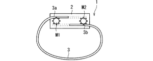
図34は、装着型機器1の構成の一例を概略的に示す図である。図34の例示では、締付機構231はモータM1,M2を有している。モータM1,M2は制御部21によって制御されて回転する。各モータM1,M2の外周には、周方向に沿って複数の凸部が立設されている。つまり、このモータM1,M2は、回転軸に沿って見て、歯車形状を有している。一方で、ベルト部3の一端3a側の内周面には、その長手方向に沿って複数の凹部が形成され、ベルト部3の他端3b側の外周面には、その長手方向に沿って複数の凹部が形成されている。ベルト部3の一端3a側の凹部はモータM1の凸部と嵌合し、ベルト部3の他端3b側の凹部はモータM2の凸部と嵌合する。   FIG. 34 is a diagram schematically illustrating an example of the configuration of the wearable device 1. In the example of FIG. 34, the tightening mechanism 231 includes motors M1 and M2. The motors M1 and M2 are controlled by the control unit 21 and rotate. On the outer periphery of each of the motors M1 and M2, a plurality of convex portions are erected along the circumferential direction. That is, the motors M1 and M2 have a gear shape when viewed along the rotation axis. On the other hand, a plurality of recesses are formed along the longitudinal direction on the inner peripheral surface on the one end 3a side of the belt portion 3, and the outer peripheral surface on the other end 3b side of the belt portion 3 along the longitudinal direction. A plurality of recesses are formed. The concave portion on the one end 3a side of the belt portion 3 is fitted to the convex portion of the motor M1, and the concave portion on the other end 3b side of the belt portion 3 is fitted to the convex portion of the motor M2.

これらのモータM1,M2がそれぞれ回転することで、ベルトコンベアと同様の原理によって、ベルト部3の一端3aおよび他端3bを、それぞれ本体部2の内部へと移動させることができる。図35は、装着型機器1の構成の一例を概略的に示している。図35の装着型機器1においては、図34と比較して、ベルト部3の一端3aおよび他端3bが本体部2のより内部に位置している。よって、バンド部3のうち本体部2から延びる部分の周の長さは、図34の装着型機器1のそれに比べて短い。よって、バンド部3がユーザの腕を締め付けることができる。制御部21は、例えばこれらモータM1,M2の出力トルクを制御することで、締め付け力を制御することができる。   By rotating these motors M1 and M2, respectively, one end 3a and the other end 3b of the belt portion 3 can be moved into the main body portion 2 by the same principle as the belt conveyor. FIG. 35 schematically illustrates an example of the configuration of the wearable device 1. In the wearable device 1 of FIG. 35, one end 3 a and the other end 3 b of the belt portion 3 are located inside the main body portion 2 as compared with FIG. 34. Therefore, the circumference length of the part extended from the main-body part 2 among the band parts 3 is short compared with that of the wearable apparatus 1 of FIG. Therefore, the band part 3 can tighten a user's arm. For example, the control unit 21 can control the tightening force by controlling the output torque of the motors M1 and M2.

逆に、モータM1,M2が、締め付けとは反対方向に回転することにより、本体部2から延びるバンド部3の周の長さが長くなる。これにより、モータM1,M2はバンド部3による腕の締め付けを緩めることができる。   On the contrary, when the motors M1 and M2 rotate in the direction opposite to the tightening, the circumferential length of the band part 3 extending from the main body part 2 becomes longer. Thus, the motors M1 and M2 can loosen the arm tightening by the band portion 3.

なお図34および図35で示される本体部2において、破線で囲まれた領域は、ベルト部3がその長手方向に挿入可能な空間を示している。   In the main body 2 shown in FIGS. 34 and 35, a region surrounded by a broken line indicates a space in which the belt 3 can be inserted in the longitudinal direction.

図36および図37は、装着型機器1の構成の一例を概略的に示す図である。図36および図37の例示では、締付機構231が本体部2の外部に設けられている。例えば締付機構231は、本体部2と向かい合って配置されている。言い換えれば、締付機構231は、装着型機器1が形成する輪の中心に対して、本体部2とは反対側に位置している。図36の締付機構231の具体的な構造は図32と同様であり、図37の締付機構231の具体的な構造は図34と同様であるので、繰り返しの説明を避ける。   36 and 37 are diagrams schematically illustrating an example of the configuration of the wearable device 1. 36 and 37, the tightening mechanism 231 is provided outside the main body 2. For example, the tightening mechanism 231 is disposed to face the main body 2. In other words, the tightening mechanism 231 is located on the side opposite to the main body 2 with respect to the center of the ring formed by the wearable device 1. The specific structure of the tightening mechanism 231 shown in FIG. 36 is the same as that shown in FIG. 32, and the specific structure of the tightening mechanism 231 shown in FIG. 37 is the same as that shown in FIG.

以上のように、装着型機器1は詳細に説明されたが、上記した説明は、全ての局面において例示であって、この開示がそれに限定されるものではない。また、上述した各種変形例は、相互に矛盾しない限り組み合わせて適用可能である。そして、例示されていない無数の変形例が、この開示の範囲から外れることなく想定され得るものと解される。   As described above, the wearable device 1 has been described in detail. However, the above description is an example in all aspects, and the disclosure is not limited thereto. The various modifications described above can be applied in combination as long as they do not contradict each other. And it is understood that the countless modification which is not illustrated can be assumed without deviating from the scope of this disclosure.

1 装着型機器
3 バンド部
21 制御部
22 通信部
23 刺激部
26 センサ
231 締付機構
232 冷熱素子
233 振動部
28 現在位置取得部
Pg1 制御プログラム
DESCRIPTION OF SYMBOLS 1 Wearable apparatus 3 Band part 21 Control part 22 Communication part 23 Stimulation part 26 Sensor 231 Tightening mechanism 232 Cooling element 233 Vibration part 28 Current position acquisition part Pg1 Control program

Claims (19)

第1ユーザに装着される装着型機器であって、
物理量に基づく第1情報を受信する第1通信部と、
可制御の刺激量で第1ユーザの皮膚の感覚器を刺激する刺激部と、
前記第1情報に基づいて、前記物理量を前記感覚器で再現するように、前記刺激部に前記感覚器を刺激させる第1処理部と
を備える、装着型機器。
A wearable device worn by a first user,
A first communication unit that receives first information based on a physical quantity;
A stimulation unit that stimulates the sensory organs of the first user's skin with a controllable stimulation amount;
A wearable device comprising: a first processing unit that causes the stimulation unit to stimulate the sensory organ so that the physical quantity is reproduced by the sensory device based on the first information.
請求項1に記載の装着型機器であって、
前記物理量は、前記感覚器によって知覚可能な物理量である、装着型機器。
The wearable device according to claim 1,
The wearable device, wherein the physical quantity is a physical quantity that can be perceived by the sensory organ.
請求項2に記載の装着型機器であって、
前記物理量は力を含み、
前記刺激部は、
第1バンド部と、
前記第1バンド部を用いて、可制御の締め付け力で前記第1ユーザの体の一部を締め付ける第1締付機構と
を有し、
前記第1処理部は、前記力を前記締め付け力で再現すべく、前記第1情報に基づいて、前記第1締付機構に前記第1ユーザの体の前記一部を締め付けさせる、装着型機器。
The wearable device according to claim 2,
The physical quantity includes force,
The stimulator is
A first band part;
A first tightening mechanism for tightening a part of the body of the first user with a controllable tightening force using the first band portion;
The first processing unit causes the first tightening mechanism to tighten the part of the first user's body based on the first information in order to reproduce the force with the tightening force. .
請求項3に記載の装着型機器と、
第2装着型機器と
を備え、
前記第2装着型機器は、
前記第1通信部と通信可能な第2通信部と、
力を前記物理量として検出する第1センサと、
前記第1センサによって検出された力に基づく情報を前記第1情報として、前記第2通信部を介して、前記装着型機器へと送信する第2処理部と
を備える、装着型機器システム。
The wearable device according to claim 3,
A second wearable device,
The second wearable device is:
A second communication unit capable of communicating with the first communication unit;
A first sensor for detecting force as the physical quantity;
A wearable device system comprising: a second processing unit that transmits information based on the force detected by the first sensor as the first information to the wearable device via the second communication unit.
請求項4に記載の装着型機器システムであって、
前記装着型機器は、力を検出する第2センサを更に備え、
前記第1処理部は、前記第2センサによって検出された力に基づく第2情報を、前記第1通信部を介して前記第2装着型機器へと送信し、
前記第2装着型機器は、
第2バンド部と、
前記第2バンド部を用いて、可制御の締め付け力で第2ユーザを締め付ける第2締付機構と、
前記第2通信部を介して前記第2情報を受信し、前記第2センサによって検出された力を再現すべく、前記第2情報に基づいて、前記第2締付機構に前記第2バンド部を締め付けさせる第2処理部と
を更に備える、装着型機器システム。
The wearable device system according to claim 4,
The wearable device further includes a second sensor for detecting force,
The first processing unit transmits second information based on the force detected by the second sensor to the second wearable device via the first communication unit,
The second wearable device is:
A second band part;
A second tightening mechanism for tightening the second user with a controllable tightening force using the second band portion;
Based on the second information, the second band unit receives the second information via the second communication unit and reproduces the force detected by the second sensor. A wearable device system, further comprising: a second processing unit for tightening.
請求項2または請求項3に記載の装着型機器であって、
前記物理量は温度を含み、
前記刺激部は、可制御の熱を発生または吸収する冷熱素子を有し、
前記第1処理部は、前記温度を再現すべく、前記第1情報に基づいて、前記冷熱素子を制御する、装着型機器。
The wearable device according to claim 2 or claim 3,
The physical quantity includes temperature,
The stimulator has a cooling element that generates or absorbs controllable heat,
The first processing unit is a wearable device that controls the thermal element based on the first information in order to reproduce the temperature.
請求項6に記載の装着型機器であって、
前記物理量は複数の位置における温度を含み、
前記冷熱素子は複数の冷熱素子を含み、
前記第1処理部は、前記温度の分布を再現すべく、前記複数の冷熱素子を制御する、装着型機器。
The wearable device according to claim 6,
The physical quantity includes temperatures at a plurality of positions,
The cooling element includes a plurality of cooling elements,
The first processing unit is a wearable device that controls the plurality of cooling elements to reproduce the temperature distribution.
請求項6または請求項7に記載の装着型機器と、
第2装着型機器と
を備え、
前記第2装着型機器は、
温度を検出するセンサと、
前記温度に基づく情報を、前記第1情報として前記装着型機器へと送信する第2通信部と
を備える、装着型機器システム。
The wearable device according to claim 6 or 7,
A second wearable device,
The second wearable device is:
A sensor for detecting the temperature;
A wearable device system comprising: a second communication unit that transmits information based on the temperature as the first information to the wearable device.
請求項1に記載の装着型機器であって、
前記物理量は周期的に変化し、
前記第1処理部は、前記第1情報に基づいて、前記物理量の周期で前記刺激部に前記感覚器を刺激させる、装着型機器。
The wearable device according to claim 1,
The physical quantity changes periodically,
The first processing unit is a wearable device that causes the stimulation unit to stimulate the sensory sensation in a cycle of the physical quantity based on the first information.
請求項9に記載の装着型機器であって、
前記刺激部は、
バンド部と、
前記バンド部を用いて、可制御の締め付け力で前記第1ユーザの体の一部を締め付ける締付機構と
を有し、
前記第1処理部は、前記第1情報に基づいて、前記物理量の周期で前記締付機構に前記第1ユーザの体の前記一部を締め付けさせる、装着型機器。
The wearable device according to claim 9, wherein
The stimulator is
The band part,
A tightening mechanism for tightening a part of the body of the first user with a controllable tightening force using the band portion;
The first processing unit is a wearable device that causes the tightening mechanism to tighten the part of the body of the first user based on the first information at a cycle of the physical quantity.
請求項9または請求項10に記載の装着型機器であって、
前記刺激部は、振動部を含み、
前記第1処理部は、前記第1情報に基づいて、前記物理量の周期で、前記振動部を振動させる、装着型機器。
The wearable device according to claim 9 or 10, wherein
The stimulation unit includes a vibration unit,
The first processing unit is a wearable device that vibrates the vibration unit at a cycle of the physical quantity based on the first information.
請求項9から請求項11のいずれか一つに記載の装着型機器と、
第2装着型機器と
を備え、
前記第2装着型機器は、
周期的に変化する生体情報を検出するセンサと、
前記生体情報に基づく情報を、前記第1情報として前記装着型機器へと送信する第2通信部と
を備える、装着型機器システム。
The wearable device according to any one of claims 9 to 11,
A second wearable device,
The second wearable device is:
A sensor that detects biological information that periodically changes;
A wearable device system comprising: a second communication unit that transmits information based on the biological information as the first information to the wearable device.
請求項9から請求項11のいずれか一つに記載の装着型機器と、
第2装着型機器と
を備え、
前記第2装着型機器は、
加速度を検出するセンサと、
前記加速度に基づく情報を、前記第1情報として前記装着型機器へと送信する第2通信部と
を備える、装着型機器システム。
The wearable device according to any one of claims 9 to 11,
A second wearable device,
The second wearable device is:
A sensor for detecting acceleration;
A wearable device system comprising: a second communication unit that transmits information based on the acceleration as the first information to the wearable device.
請求項1〜3,6,7,9〜11のいずれか一つに記載の装着型機器であって、
前記物理量を検出するセンサと、
入力部と
を更に備え、
前記第1処理部は、
前記物理量に基づく前記第1情報を、前記第1通信部を介して外部装置に送信して、前記外部装置に前記第1情報を格納させ、
前記入力部への入力に応答して前記外部装置から前記第1情報を取得し、
前記第1情報に基づいて、前記物理量を再現すべく、前記刺激部に前記第1ユーザの前記感覚器を刺激させる、装着型機器。
The wearable device according to any one of claims 1 to 3, 6, 7, and 9 to 11,
A sensor for detecting the physical quantity;
An input unit,
The first processing unit includes:
Transmitting the first information based on the physical quantity to an external device via the first communication unit, and storing the first information in the external device;
Obtaining the first information from the external device in response to an input to the input unit;
A wearable device that causes the stimulation unit to stimulate the sensory sensation of the first user in order to reproduce the physical quantity based on the first information.
請求項9に記載の装着型機器であって、
加速度を繰り返し検出するセンサと、
前記装着型機器の位置を繰り返し取得する位置取得部と、
入力部と
を更に備え、
前記第1処理部は、
前記物理量と前記位置を互いに対応付けた情報を前記第1情報として、前記第1通信部を介して外部装置へ送信して、前記第1情報をログ情報として前記外部装置に格納させ、
前記入力部への入力に応答して前記外部装置から前記第1情報を取得し、
前記第1情報に含まれる各位置における過去の前記装着型機器の空間的な動きの周期を、前記第1情報に基づいて算出し、
前記位置取得部によって取得された位置と、前記第1情報における位置との差が小さいか否かを判断し、
前記差が小さいと判断したときに、前記位置に対応する前記周期で前記刺激部に前記第1ユーザの前記感覚器を刺激させる、装着型機器。
The wearable device according to claim 9, wherein
A sensor that repeatedly detects acceleration;
A position acquisition unit that repeatedly acquires the position of the wearable device;
An input unit,
The first processing unit includes:
Transmitting information associating the physical quantity and the position with each other as the first information to the external device via the first communication unit, and storing the first information as log information in the external device;
Obtaining the first information from the external device in response to an input to the input unit;
Calculating a past spatial movement cycle of the wearable device at each position included in the first information based on the first information;
Determining whether the difference between the position acquired by the position acquisition unit and the position in the first information is small;
A wearable device that causes the stimulation unit to stimulate the sensory sensation of the first user at the cycle corresponding to the position when it is determined that the difference is small.
互いに通信可能な第1装着型機器および第2装着型機器を備え、
前記第1装着型機器は物理量を検出するセンサを備え、
前記第2装着型機器は、
可制御の刺激量でユーザの感覚器を刺激する刺激部と、
前記物理量を前記感覚器で再現するように、前記刺激部に前記感覚器を刺激させる処理部と
を備える、装着型機器システム。
A first wearable device and a second wearable device capable of communicating with each other;
The first wearable device includes a sensor for detecting a physical quantity,
The second wearable device is:
A stimulator that stimulates the user's sensory organs with a controllable amount of stimulus;
A wearable device system comprising: a processing unit that causes the stimulation unit to stimulate the sensory organ so that the physical quantity is reproduced by the sensory device.
ユーザに装着される装着型機器の制御方法であって、
物理量に基づく第1情報を受信し、
前記第1情報に基づいて、前記物理量を前記ユーザの感覚器で再現するように、刺激部に前記感覚器を刺激させる、装着型機器の制御方法。
A control method for a wearable device worn by a user,
Receiving first information based on a physical quantity;
A control method for a wearable device that causes a stimulation unit to stimulate the sensory device so that the physical quantity is reproduced by the user's sensory device based on the first information.
物理量に基づく第1情報を受信する第1通信部と、
可制御の刺激量で第1ユーザの皮膚の感覚器を刺激する刺激部と
を備える装着型機器の制御装置であって、
前記第1情報に基づいて、前記物理量を前記感覚器で再現するように、前記刺激部に前記感覚器を刺激させる処理部を備える、装着型機器の制御装置。
A first communication unit that receives first information based on a physical quantity;
A control device for a wearable device comprising a stimulation unit that stimulates a sensory organ of the first user's skin with a controllable stimulation amount,
A control device for a wearable device, comprising: a processing unit that causes the stimulation unit to stimulate the sensory device so that the physical quantity is reproduced by the sensory device based on the first information.
物理量に基づく第1情報を受信する第1通信部と、
可制御の刺激量で第1ユーザの皮膚の感覚器を刺激する刺激部と
を備える装着型機器の制御プログラムであって、
前記装着型機器に、前記第1情報に基づいて、前記物理量を前記感覚器で再現するように、前記刺激部に前記感覚器を刺激させる処理を実行させる、制御プログラム。
A first communication unit that receives first information based on a physical quantity;
A control program for a wearable device comprising: a stimulator that stimulates a sensory organ of the first user's skin with a controllable stimulus amount,
A control program for causing the wearable device to execute a process of causing the stimulation unit to stimulate the sensory device so that the physical quantity is reproduced by the sensory device based on the first information.
JP2016106135A 2016-05-27 2016-05-27 Wearable apparatus, wearable apparatus system, control method of wearable apparatus, control device of wearable apparatus, and control program Pending JP2017211911A (en)

Priority Applications (3)

Application Number Priority Date Filing Date Title
JP2016106135A JP2017211911A (en) 2016-05-27 2016-05-27 Wearable apparatus, wearable apparatus system, control method of wearable apparatus, control device of wearable apparatus, and control program
US16/305,013 US11300998B2 (en) 2016-05-27 2017-05-24 Wearable device to stimulate sense organs in the skin of a user, wearable device system, and method for controlling wearable device
PCT/JP2017/019316 WO2017204242A1 (en) 2016-05-27 2017-05-24 Wearable device, wearable device system, and method for controlling wearable device

Applications Claiming Priority (1)

Application Number Priority Date Filing Date Title
JP2016106135A JP2017211911A (en) 2016-05-27 2016-05-27 Wearable apparatus, wearable apparatus system, control method of wearable apparatus, control device of wearable apparatus, and control program

Publications (1)

Publication Number Publication Date
JP2017211911A true JP2017211911A (en) 2017-11-30

Family

ID=60411402

Family Applications (1)

Application Number Title Priority Date Filing Date
JP2016106135A Pending JP2017211911A (en) 2016-05-27 2016-05-27 Wearable apparatus, wearable apparatus system, control method of wearable apparatus, control device of wearable apparatus, and control program

Country Status (3)

Country Link
US (1) US11300998B2 (en)
JP (1) JP2017211911A (en)
WO (1) WO2017204242A1 (en)

Cited By (3)

* Cited by examiner, † Cited by third party
Publication number Priority date Publication date Assignee Title
WO2020161921A1 (en) * 2019-02-08 2020-08-13 株式会社ソニー・インタラクティブエンタテインメント Winding device, cradle, and mounting system
JP2021022005A (en) * 2019-07-24 2021-02-18 トヨタ紡織株式会社 Information processing device and control method
JPWO2021157049A1 (en) * 2020-02-07 2021-08-12

Families Citing this family (3)

* Cited by examiner, † Cited by third party
Publication number Priority date Publication date Assignee Title
JP6894252B2 (en) * 2017-02-16 2021-06-30 日本光電工業株式会社 Sensor device and watching device
AU2019283182B2 (en) * 2018-06-05 2021-03-04 Kazuo Tani Blood flow volume measurement system
EP4054408A4 (en) * 2019-11-07 2023-11-08 Thump, Inc. Systems, devices, and methods including a heartbeat mimetic

Family Cites Families (10)

* Cited by examiner, † Cited by third party
Publication number Priority date Publication date Assignee Title
JP2007143812A (en) 2005-11-28 2007-06-14 Seiko Epson Corp Mounting type device
US8123660B2 (en) * 2007-12-28 2012-02-28 Immersion Corporation Method and apparatus for providing communications with haptic cues
CN103930851B (en) * 2011-11-15 2016-09-21 索尼公司 Messaging device and method
US9746945B2 (en) * 2011-12-19 2017-08-29 Qualcomm Incorporated Integrating sensation functionalities into a mobile device using a haptic sleeve
JP6103350B2 (en) * 2012-12-18 2017-03-29 カシオ計算機株式会社 Exercise support device, exercise support method, and exercise support program
DE202014010799U1 (en) * 2013-10-29 2016-10-19 Nordin Kouache System for transmitting tactile instructions to a human body
JP6094476B2 (en) * 2013-12-27 2017-03-15 カシオ計算機株式会社 Imaging system, control method therefor, and control program therefor
KR102244856B1 (en) * 2014-04-22 2021-04-27 삼성전자 주식회사 Method for providing user interaction with wearable device and wearable device implenenting thereof
JP2016051319A (en) * 2014-08-29 2016-04-11 ソニー株式会社 Force sense presentation device, force sense presentation system and force sense presentation method
WO2016168117A2 (en) * 2015-04-14 2016-10-20 John James Daniels Wearable electric, multi-sensory, human/machine, human/human interfaces

Cited By (5)

* Cited by examiner, † Cited by third party
Publication number Priority date Publication date Assignee Title
WO2020161921A1 (en) * 2019-02-08 2020-08-13 株式会社ソニー・インタラクティブエンタテインメント Winding device, cradle, and mounting system
JPWO2020161921A1 (en) * 2019-02-08 2021-10-28 株式会社ソニー・インタラクティブエンタテインメント Winding device, cradle and mounting system
JP7160955B2 (en) 2019-02-08 2022-10-25 株式会社ソニー・インタラクティブエンタテインメント Winders, cradles and mounting systems
JP2021022005A (en) * 2019-07-24 2021-02-18 トヨタ紡織株式会社 Information processing device and control method
JPWO2021157049A1 (en) * 2020-02-07 2021-08-12

Also Published As

Publication number Publication date
US11300998B2 (en) 2022-04-12
US20210223817A1 (en) 2021-07-22
WO2017204242A1 (en) 2017-11-30

Similar Documents

Publication Publication Date Title
WO2017204242A1 (en) Wearable device, wearable device system, and method for controlling wearable device
US20220091816A1 (en) Wireless Earpiece with a Passive Virtual Assistant
US11045117B2 (en) Systems and methods for determining axial orientation and location of a user&#39;s wrist
US10313779B2 (en) Voice assistant system for wireless earpieces
JP6878569B2 (en) Wearable computer with connectivity to health equipment for improved behavioral monitoring
US20180060031A1 (en) Voice assistant for wireless earpieces
CN105807913B (en) Wearable device, system and operation method based on biological information
CN104007818B (en) Mobile device with instinct warning
KR101824921B1 (en) Method And Apparatus For Performing Communication Service Based On Gesture
JP2019166327A (en) Method and system for transmitting touch sense instruction to human body
JP2017151950A (en) Haptic effects conflict avoidance
US20150187188A1 (en) Communications using tactile stimuli on wearable devices
US11036293B2 (en) Method for using fingers to interact with a smart glove worn on a hand
JP6837407B2 (en) Electronic devices, servers, data structures, physical condition management methods and physical condition management programs
KR20170104541A (en) Navigation devices and methods
WO2015083183A1 (en) Hand wearable haptic feedback based navigation device
JP2011516915A (en) Motion content-based learning apparatus and method
US20140335494A1 (en) Systems and methods for facilitating coaching and/or analysis of pressure-based treatment
JP7116810B2 (en) Wearable Computers with Connectivity to Health Devices for Improved Behavioral Monitoring Using Calorie Expenditure Models
JP2020013549A (en) Adaptive haptic effect rendering based on dynamic system identification
WO2017094211A1 (en) Sense of force presentation device, recognition device, control device, and sense of force presentation method
JP6908027B2 (en) Motion measuring device, information processing device and motion measuring method
JPWO2011148855A1 (en) Massage equipment
KR102083466B1 (en) Apparatus for recommending music, method thereof and computer recordable medium storing program to perform the method
WO2019124068A1 (en) Information processing device and method, and program