JP2017206066A - Unmanned aircraft for spraying chemical solution - Google Patents
Unmanned aircraft for spraying chemical solution Download PDFInfo
- Publication number
- JP2017206066A JP2017206066A JP2016098246A JP2016098246A JP2017206066A JP 2017206066 A JP2017206066 A JP 2017206066A JP 2016098246 A JP2016098246 A JP 2016098246A JP 2016098246 A JP2016098246 A JP 2016098246A JP 2017206066 A JP2017206066 A JP 2017206066A
- Authority
- JP
- Japan
- Prior art keywords
- flight
- spraying
- spray
- chemical
- chemical liquid
- Prior art date
- Legal status (The legal status is an assumption and is not a legal conclusion. Google has not performed a legal analysis and makes no representation as to the accuracy of the status listed.)
- Pending
Links
- 239000000126 substance Substances 0.000 title claims abstract description 318
- 238000005507 spraying Methods 0.000 title claims abstract description 191
- 239000007921 spray Substances 0.000 claims abstract description 112
- RZVHIXYEVGDQDX-UHFFFAOYSA-N 9,10-anthraquinone Chemical compound C1=CC=C2C(=O)C3=CC=CC=C3C(=O)C2=C1 RZVHIXYEVGDQDX-UHFFFAOYSA-N 0.000 claims abstract description 32
- 239000007788 liquid Substances 0.000 claims description 103
- 238000009792 diffusion process Methods 0.000 claims description 22
- 238000000034 method Methods 0.000 claims description 17
- 238000001514 detection method Methods 0.000 claims description 16
- 230000008569 process Effects 0.000 claims description 8
- 239000000243 solution Substances 0.000 description 66
- 239000008155 medical solution Substances 0.000 description 26
- 238000004891 communication Methods 0.000 description 25
- 230000007480 spreading Effects 0.000 description 9
- 238000003892 spreading Methods 0.000 description 9
- 230000008859 change Effects 0.000 description 6
- 230000001133 acceleration Effects 0.000 description 5
- 239000003905 agrochemical Substances 0.000 description 5
- 238000009434 installation Methods 0.000 description 5
- 238000006243 chemical reaction Methods 0.000 description 4
- 239000006185 dispersion Substances 0.000 description 4
- 238000009826 distribution Methods 0.000 description 4
- 239000002184 metal Substances 0.000 description 4
- 230000001141 propulsive effect Effects 0.000 description 4
- 239000011347 resin Substances 0.000 description 4
- 229920005989 resin Polymers 0.000 description 4
- 241000607479 Yersinia pestis Species 0.000 description 3
- 230000003247 decreasing effect Effects 0.000 description 3
- 201000010099 disease Diseases 0.000 description 3
- 208000037265 diseases, disorders, signs and symptoms Diseases 0.000 description 3
- 238000009472 formulation Methods 0.000 description 3
- 239000000203 mixture Substances 0.000 description 3
- 239000000575 pesticide Substances 0.000 description 3
- 238000005452 bending Methods 0.000 description 2
- 238000002347 injection Methods 0.000 description 2
- 239000007924 injection Substances 0.000 description 2
- 239000004973 liquid crystal related substance Substances 0.000 description 2
- 239000000463 material Substances 0.000 description 2
- 238000012545 processing Methods 0.000 description 2
- 230000004044 response Effects 0.000 description 2
- 238000004088 simulation Methods 0.000 description 2
- OKTJSMMVPCPJKN-UHFFFAOYSA-N Carbon Chemical compound [C] OKTJSMMVPCPJKN-UHFFFAOYSA-N 0.000 description 1
- 230000008901 benefit Effects 0.000 description 1
- 238000007664 blowing Methods 0.000 description 1
- 229910052799 carbon Inorganic materials 0.000 description 1
- 239000011248 coating agent Substances 0.000 description 1
- 238000000576 coating method Methods 0.000 description 1
- 238000013461 design Methods 0.000 description 1
- 238000010586 diagram Methods 0.000 description 1
- 239000003814 drug Substances 0.000 description 1
- 230000000694 effects Effects 0.000 description 1
- 238000005516 engineering process Methods 0.000 description 1
- 238000002474 experimental method Methods 0.000 description 1
- 239000003337 fertilizer Substances 0.000 description 1
- 230000006870 function Effects 0.000 description 1
- 230000012447 hatching Effects 0.000 description 1
- 238000003384 imaging method Methods 0.000 description 1
- 230000007246 mechanism Effects 0.000 description 1
- 239000003973 paint Substances 0.000 description 1
- 238000002360 preparation method Methods 0.000 description 1
- 238000005086 pumping Methods 0.000 description 1
- 238000003860 storage Methods 0.000 description 1
- 238000012876 topography Methods 0.000 description 1
Images


Landscapes
- Catching Or Destruction (AREA)
- Control Of Position, Course, Altitude, Or Attitude Of Moving Bodies (AREA)
Abstract
Description
本発明は、農薬等の薬液を空中散布する薬液散布用無人航空機に関し、特に薬液の散布量を高精度に制御することで単位面積当たりの散布量を均一にするとともに、所望の散布対象領域の外側に薬液が飛散するのを防止する上で好適な薬液散布用無人航空機に関する。 The present invention relates to an unmanned aerial vehicle for spraying chemicals such as agricultural chemicals in the air, and in particular, by uniformly controlling the spraying amount of the chemical solution, the spraying amount per unit area is made uniform, and the desired spraying target region The present invention relates to an unmanned aerial vehicle for spraying chemicals suitable for preventing chemicals from splashing outside.
従来より農薬等の薬液を無人ヘリコプターにより農作地へ空中散布することが行われている。このような無人ヘリコプターには、薬液を貯留する薬液タンクと、薬液タンク中の薬液を圧送するためのポンプと、ポンプにより圧送されてきた薬液を散布するノズルが実装されている。無人ヘリコプターは、散布対象領域となる農作地上に予め飛行経路を設定し、その飛行経路上を飛行しつつノズルから薬液を散布する。 Conventionally, chemical solutions such as agricultural chemicals are sprayed in the air on agricultural land by unmanned helicopters. Such an unmanned helicopter is equipped with a chemical solution tank for storing a chemical solution, a pump for pumping the chemical solution in the chemical solution tank, and a nozzle for spraying the chemical solution fed by the pump. The unmanned helicopter sets a flight path in advance on the agricultural ground as a spray target area, and sprays the chemical solution from the nozzle while flying on the flight path.
従来の無人ヘリコプターは、風が強い場合において安定した飛行軌道が描けない場合が多く、所望の散布対象領域に対して薬液を効率よく散布することができない場合もある。これに加えて散布した薬液が風によって飛散してしまい、散布対象領域外まで飛んでしまう、いわゆるドリフトが生じてしまう場合もある。その結果、散布対象領域外にある他の作物に薬液が付着したり、車や建築構造物にも薬液が付着してしまい、トラブルの原因にもなっていた。 Conventional unmanned helicopters often fail to draw a stable flight trajectory when the wind is strong, and may not be able to efficiently spray a chemical solution to a desired spray target region. In addition to this, the sprayed chemical liquid may be scattered by the wind, and a so-called drift may occur in which the chemical liquid flies outside the spray target area. As a result, the chemical solution adheres to other crops outside the spraying target area, or the chemical solution also adheres to the car or the building structure, causing trouble.
これに加えて、上述した無人ヘリコプターの不安定な飛行やドリフトが生じた場合には、散布対象領域内の農作地における単位面積当たりの散布量を均一に調整することができない。その結果、同じ散布対象領域内においても薬液の散布量にムラが生じてしまい、薬液の散布量が多くなった領域においてはいわゆる農薬焼けが発生し、却って農作物を枯らしてしまう原因にもなる。また薬液の散布量が少なくなった領域については、農作物の病気を防止することが必ずしもできず、また害虫を完全に死滅させることができず農作物の被害が後を絶たない。 In addition, when the above-described unstable flight or drift of the unmanned helicopter occurs, it is not possible to uniformly adjust the spraying amount per unit area on the farmland in the spraying target region. As a result, even within the same spraying target area, the spraying amount of the chemical solution is uneven, and in the region where the spraying amount of the chemical solution is large, so-called pesticide burning occurs, which causes the crops to wither. Also, in areas where the amount of sprayed chemicals is reduced, it is not always possible to prevent crop diseases, and pests cannot be completely killed, causing damage to crops.
特にこの農薬等の薬液は、少量でも効果が発揮されるように、農作物毎に成分が詳細に規定されているため、散布量にムラがある場合には、所期の効果を発揮させることができない。 In particular, chemicals such as pesticides are specified in detail for each crop so that the effect can be achieved even in small amounts. Can not.
従来において特許文献1には、無人ヘリコプターによる薬液の散布濃度を調整する技術は開示されている。この特許文献1の開示技術によれば、風向、風力の入力を受けて、風下側には所定の幅に亘り散布を行わない領域を設けるように設定を行う。これにより、散布対象領域外への薬液の不用意な散布を防止することができる。これに加えて無人ヘリコプターにおける飛行高度の調整が比較的容易であることを活かし、飛行高度を制御することで散布濃度を調整する技術も開示されている。
Conventionally,
ところで上述した特許文献1の開示技術は、あくまで無人ヘリコプターの大型化や複雑化を招くことなく、散布対象領域における薬液散布濃度を調整することを目的とした技術である。このため、大型化や複雑化に繋がるような設計変更を無人ヘリコプター側に課すのではなく、無人ヘリコプターの飛行経路や飛行高度を最適化することに主眼を置いている。
By the way, the technique disclosed in
しかしながら、この特許文献1の開示技術によれば、突発的に吹く風に対しするドリフトをリアルタイムに防止し、散布対象領域内の農作地における単位面積当たりの散布量を均一にするためのリアルタイムな調整を図ることについては特段開示されていない。特に散布対象領域におけるにおける地形や気象状況により、実際の現場にて無人ヘリコプターを飛行させた場合に、当初に綿密に設定した飛行経路や飛行高度から僅かに外れてしまうことは通常起こりえることである。このような現場での各種状況の変化に対して無人ヘリコプター側において柔軟に対応し、散布対象領域に対して薬液をムラなく散布し、ドリフトをも防止できる技術が従来より望まれていた。
However, according to the technology disclosed in
そこで本発明は、上述した問題点に鑑みて案出されたものであり、その目的とするところは、薬液の散布量を高精度に制御することで単位面積当たりの散布量を均一にするとともに、所望の散布対象領域の外側に薬液が飛散するドリフトを防止することが可能な薬液散布用無人航空機を提供することにある。 Therefore, the present invention has been devised in view of the above-described problems, and the object of the present invention is to uniformize the spraying amount per unit area by controlling the spraying amount of the chemical solution with high accuracy. Another object of the present invention is to provide an unmanned aircraft for spraying chemicals capable of preventing drift of chemicals scattered outside a desired spray target area.
第1発明に係る薬液散布用無人航空機は、予め入力された散布対象領域に対して薬液タンクに貯留されている薬液を散布する薬液散布用無人航空機において、上記散布対象領域に対して設定された飛行経路上を飛行するように制御する飛行制御手段と、上記飛行経路の飛行時における飛行速度を検出する飛行速度検出手段と、上記飛行速度検出手段により検出された飛行速度に基づいて、上記薬液タンクに貯留されている薬液の散布量を制御する散布制御手段とを備えることを特徴とする。 The unmanned aerial vehicle for spraying chemicals according to the first aspect of the present invention is an unmanned aircraft for spraying chemicals that sprays a chemical stored in a chemical tank on a spray target region that is input in advance, and is set for the spray target region. Flight control means for controlling to fly on a flight path, flight speed detection means for detecting a flight speed at the time of flight of the flight path, and the liquid medicine based on the flight speed detected by the flight speed detection means And a spray control means for controlling the spray amount of the chemical stored in the tank.
第2発明に係る薬液散布用無人航空機は、第1発明において、上記飛行経路の飛行時における各位置情報をリアルタイムで取得する位置情報取得手段を更に備え、上記飛行制御手段は、上記位置情報取得手段により取得された位置情報の上記散布対象領域との関係に基づいて飛行速度を制御することを特徴とする。 The unmanned aerial vehicle for spraying chemicals according to a second aspect of the present invention further comprises position information acquisition means for acquiring each position information at the time of flight of the flight route in the first invention, and the flight control means is configured to acquire the position information. The flight speed is controlled based on the relationship between the position information acquired by the means and the region to be scattered.
第3発明に係る薬液散布用無人航空機は、予め入力された散布対象領域に対して薬液タンクに貯留されている薬液を散布する薬液散布用無人航空機において、上記散布対象領域に対して設定された飛行経路上を飛行するように制御する飛行制御手段と、上記飛行経路の飛行時における各位置情報をリアルタイムで取得する位置情報取得手段と、上記薬液タンクに貯留されている薬液を複数の散布口を介して散布可能な散布制御手段とを備え、上記位置情報取得手段により取得された位置情報の上記散布対象領域との関係に基づいて、上記複数の散布口のうち何れか1以上を閉口させることを特徴とする。 The unmanned aerial vehicle for spraying chemicals according to the third aspect of the present invention is an unmanned aircraft for spraying chemicals that sprays a chemical stored in a chemical tank on a spray target region that is input in advance, and is set for the spray target region. Flight control means for controlling to fly on the flight path, position information acquisition means for acquiring each position information at the time of flight of the flight path in real time, and a plurality of spray ports for the chemical liquid stored in the chemical liquid tank A spray control unit capable of spraying via the position information, and closes one or more of the plurality of spray ports based on the relationship between the position information acquired by the position information acquisition unit and the region to be sprayed. It is characterized by that.
第4発明に係る薬液散布用無人航空機は、予め入力された散布対象領域に対して薬液タンクに貯留されている薬液を散布する薬液散布用無人航空機において、上記散布対象領域に対して設定された飛行経路上を飛行するように制御する飛行制御手段と、上記飛行経路の飛行時における飛行高度を検出する飛行高度検出手段と、上記飛行高度検出手段により検出された飛行高度に基づいて、上記薬液タンクに貯留されている薬液の散布量並びにその薬液の拡散角度の何れか1以上を制御する散布制御手段とを備えることを特徴とする。 The unmanned aerial vehicle for spraying chemicals according to the fourth aspect of the present invention is an unmanned aircraft for spraying chemicals that sprays a chemical stored in a chemical tank on a spray target region that is input in advance, and is set for the spray target region. Flight control means for controlling to fly on the flight path, flight altitude detection means for detecting the flight altitude at the time of flight of the flight path, and the chemical solution based on the flight altitude detected by the flight altitude detection means A spray control means for controlling any one or more of the spray amount of the chemical solution stored in the tank and the diffusion angle of the chemical solution is provided.
第5発明に係る薬液散布用無人航空機は、第4発明において、上記飛行経路の飛行時における各位置情報をリアルタイムで取得する位置情報取得手段を更に備え、上記散布制御手段は、上記位置情報取得手段により取得された位置情報の上記散布対象領域との関係に基づいて、上記薬液タンクに貯留されている薬液の散布量並びにその薬液の拡散角度の何れか1以上を制御することを特徴とする。 The unmanned aerial vehicle for spraying chemicals according to a fifth aspect of the present invention is the unmanned aircraft for spraying chemical liquid according to the fourth aspect, further comprising position information acquisition means for acquiring in real time each position information at the time of flight of the flight path, Based on the relationship between the position information acquired by the means and the region to be sprayed, one or more of the spray amount of the chemical liquid stored in the chemical tank and the diffusion angle of the chemical liquid is controlled. .
第6発明に係る薬液散布用無人航空機は、予め入力された散布対象領域に対して薬液タンクに貯留されている薬液を散布する薬液散布用無人航空機において、上記散布対象領域に対して設定された飛行経路上を飛行するように制御する飛行制御手段と、上記飛行経路の飛行時における風向及び風速をリアルタイムに検出する風検知手段と、上記風検知手段により検知された風向及び風速に基づいて、上記薬液の散布方向を、上記飛行経路を飛行する過程で変化させる散布制御手段とを備えることを特徴とする。 The unmanned aerial vehicle for spraying chemicals according to the sixth aspect of the present invention is an unmanned aircraft for spraying chemicals that sprays a chemical stored in a chemical tank on a spray target region that is input in advance, and is set for the spray target region. Based on the flight control means for controlling to fly on the flight path, the wind detection means for detecting the wind direction and the wind speed in flight on the flight path in real time, and the wind direction and wind speed detected by the wind detection means, Spraying control means for changing the spraying direction of the chemical solution in the process of flying the flight path.
第7発明に係る薬液散布用無人航空機は、第6発明において、上記飛行経路の飛行時における各位置情報をリアルタイムで取得する位置情報取得手段を更に備え、上記散布制御手段は、更に上記位置情報取得手段により取得された位置情報の上記散布対象領域との関係に基づいて上記薬液の散布方向を変化させることを特徴とする。 The unmanned aerial vehicle for spraying chemicals according to a seventh aspect of the present invention further comprises position information acquisition means for acquiring in real time each position information at the time of flight of the flight path according to the sixth aspect, and the spray control means further includes the position information. The spray direction of the chemical solution is changed based on the relationship between the position information acquired by the acquisition unit and the region to be sprayed.
第8発明に係る薬液散布用無人航空機は、予め入力された散布対象領域に対して薬液タンクに貯留されている薬液を散布する薬液散布用無人航空機において、上記散布対象領域に対して設定された飛行経路上を飛行するように制御する飛行制御手段と、上記飛行経路の飛行時における風向及び風速をリアルタイムに検出する風検知手段とを備え、上記飛行制御手段は、上記風検知手段により検知された風向及び風速に基づいて、上記飛行経路を切り替えることを特徴とする。 An unmanned aerial vehicle for spraying chemicals according to an eighth aspect of the present invention is an unmanned aircraft for spraying chemicals that sprays a chemical stored in a chemical tank on a spray target region that is input in advance, and is set for the spray target region. Flight control means for controlling to fly on the flight path and wind detection means for detecting in real time the wind direction and wind speed during flight of the flight path, the flight control means being detected by the wind detection means. The flight path is switched based on the wind direction and wind speed.
第9発明に係る薬液散布用無人航空機は、第6発明〜第8発明の何れかにおいて、上記風検知手段は、上記飛行経路上を飛行する時における機体の傾斜角度及び傾斜方向に基づいて上記風向及び上記風速を検知することを特徴とする。 An unmanned aerial vehicle for spraying chemicals according to a ninth aspect of the present invention, according to any one of the sixth to eighth aspects, wherein the wind detecting means is based on an inclination angle and an inclination direction of the fuselage when flying on the flight path. The wind direction and the wind speed are detected.
上述した構成からなる本発明によれば、検出した飛行速度に基づいて薬液タンクに貯留されている薬液の散布量を制御する。これにより、散布対象領域内の農作地における単位面積当たりの薬液の散布量を均一に調整することができる。その結果、薬液の散布量にムラが生じるのを防止でき、薬液の散布量が多すぎることによる農薬焼けや、薬液の散布量が少なすぎることによる農作物の病気や害虫被害を防止することが可能となる。特に薬液散布用無人航空機の飛行速度を一定になるように設定しても、突発的な風や周辺環境の変化、或いは薬液散布用無人航空機の各構成要素に起因して、飛行速度が必ずしも一定にならず、僅かな範囲でブレてしまうことがある。かかる場合においても飛行速度の変化をリアルタイムに検知し、これに基づいて散布量を調整することで、結果としては薬液の散布量にムラが生じるのを防止できる。 According to the present invention having the above-described configuration, the spray amount of the chemical liquid stored in the chemical liquid tank is controlled based on the detected flight speed. Thereby, the spraying quantity of the chemical | medical solution per unit area in the farmland in a spraying object area | region can be adjusted uniformly. As a result, it is possible to prevent unevenness in the spraying amount of the chemical solution, and it is possible to prevent the burning of agricultural chemicals due to the excessive spraying amount of the chemical solution and the disease and pest damage to the crops caused by the spraying amount of the chemical solution being too small. It becomes. In particular, even if the flight speed of the unmanned aircraft for spraying chemicals is set to be constant, the flight speed is not necessarily constant due to sudden changes in the wind, surrounding environment, or components of the unmanned aircraft for spraying chemicals. It may be blurred in a slight range. Even in such a case, by detecting the change in the flight speed in real time and adjusting the spraying amount based on this, it is possible to prevent unevenness in the spraying amount of the chemical solution as a result.
以下、本発明を適用した薬液散布用無人航空機を実施するための形態について図面を参照しながら詳細に説明をする。 Hereinafter, an embodiment for implementing an unmanned aerial vehicle for spraying chemicals to which the present invention is applied will be described in detail with reference to the drawings.
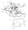
図1は、本発明を適用した薬液散布用無人航空機1並びにこれを操縦するための操縦端末2の外観構成を示している。
FIG. 1 shows an external configuration of an unmanned
薬液散布用無人航空機1は、いわゆる小型でかつ無人飛行が可能なドローン(マルチコプター)や無人ヘリコプターであり、ローター11と、ローター11を駆動するローター用モーター12と、先端にローター用モーター12が取り付けられたモーターステイ13と、モーターステイ13の根本に取り付けられた据付器具20と、据付器具20を上下から挟持する第1中央プレート16及び第2中央プレート17と、この第2中央プレート17上に設けられた制御ユニット15と、第2中央プレート17に対して上側に離間させて平行に設けられた第3中央プレート18と、この第3中央プレート18上に設けられたバッテリー14とを備えている。
The unmanned
またこの薬液散布用無人航空機1は、第1中央プレート16から下方に向けて延長する複数本の脚部26と、この脚部26の下端にそれぞれ設けられた2本のスキッド28と、この2本のスキッド28に架設されている載置用アーム27と、載置用アーム上に載置されている薬液タンク24と、脚部26から外側に向けて延長された左右一対の右側ブーム21並びに左側ブーム22と、右側ブーム21に設けられたノズル23a〜23cと、左側ブーム22に設けられたノズル23d〜23fとを備えている。
The unmanned
ローター11は、ローター用モーター12の回転に基づき回転するとともに、薬液散布用無人航空機1に対して浮力を与えることができるものである。本実施の形態においては、4基のローター11を有するクアッドコプターを例にとり説明をするが、これに限定されるものではなく、要求される飛行性能や、故障に対する信頼性、許容されるコスト等に応じて、ローター11を1基で構成したヘリコプター、ローター11を3基で構成したトリコプター、ローター11を6基で構成したヘキサコプター、ローター11を8基で構成したオクトコプターとして具現化されるものであってもよい。
The
ローター用モーター12は、ローター11それぞれに対して設けられており、バッテリー14からモーターステイ13を介して供給されてくる電力に基づいて回転動作可能とされている。ローター用モーター12は、上記の機能を有する限りにおいて限定されず、いかなる市販のものを適用することができる。ローター用モーター12を回転させることによりローター11を回転させることができ、薬液散布用無人航空機1を即座に垂直方向に向けて上昇させ又は下降させることができ、或いはその場で静止させることも可能となる。また、薬液散布用無人航空機1を前後左右に移動させる場合は、進行方向のローター用モーター12の回転数を下げ、進行方向とは反対側のローター用モーター12の回転数を上げる。これにより、薬液散布用無人航空機1は進行方向に対して前かがみの姿勢となり、進行方向に移動することが可能となる。また、ローター用モーター12の回転方向による出力の調整を行うことで、薬液散布用無人航空機1自体を回転させることも可能となる。これらローター用モーター12の回転数の制御は、制御ユニット15を介して行われる。
The
モーターステイ13は、第1中央プレート16及び第2中央プレート17から互いに異なる方向に向けて延長されている。特に4基のローター11を有するクアッドコプターで構成する場合、これらをそれぞれ支持するモーターステイ13は、平面視で互いに約90°間隔となるように延長されている。このモーターステイ13は、例えば金属製又は樹脂製、カーボン製、又はその他の材料からなる管体で構成されていてもよい。かかる場合には、このモーターステイ13の管体内にバッテリー14からの電力供給のためのケーブルを挿通させることができる。
The motor stay 13 extends from the first
第1中央プレート16及び第2中央プレート17は、互いに金属製又は樹脂製等の板状体で構成されている。この第1中央プレート16及び第2中央プレート17は、挟持させる据付器具20を介して互いに略平行となるように設けられる。第1中央プレート16には脚部26を取り付ける上で必要な図示しないネジ孔等が予め設けられている。第2中央プレート17についても同様に制御ユニット15を取り付ける上で必要なネジ孔が予め設けられている。
The
制御ユニット15は、各種制御に必要な集積回路やデバイスを収容するための筐体で構成されている。この制御ユニット15は、第2中央プレート17上に設けられたネジ孔にネジを介して固定される。この制御ユニット15のブロック構成の詳細は後述する。
The
第3中央プレート18は、金属製又は樹脂製等の板状体で構成されている。第3中央プレート18は、第2中央プレート17の表面に立設された長ネジ18aを介して固定されることで、当該第2中央プレート17に対して離間させつつ平行となるように設けられる。
The third
バッテリー14は、制御ユニット15やローター用モーター12を駆動させるために必要な電力を供給するための電池である。またバッテリー14は、ノズル23を制御する上で必要な電力も供給する。このバッテリー14は、着脱自在に構成され、充電が可能な仕様とされていてもよい。
The
脚部26の下端に設けられているスキッド28は、薬液散布用無人航空機1が地面に着陸した場合において接地させるために設けられている。同様にスキッド28間に設けられる載置用アーム27も薬液散布用無人航空機1が地面に着陸した場合において接地させる役割を担うが、これに加えて薬液タンク24を下側から支持する役割をも担う。
The
右側ブーム21及び左側ブーム22は、脚部26に対して回動装置29a、回動装置29bを介して設けられていてもよい。これにより右側ブーム21及び左側ブーム22は、この回動装置29a、回動装置29bにより図中A方向に向けて回動自在に構成されている。例えば薬液散布用無人航空機1を倉庫等に収納する場合において、取り外せるだけでなく、この回動装置29a、29bを介して右側ブーム21及び左側ブーム22を上方に向けて回動させて折り畳むことも可能となる。またこの回動装置29a、29bを介して右側ブーム21及び左側ブーム22をA方向に向けて自由に回動させることにより、ノズル23からの薬液の散布方向を調整することが可能となる。なお、右側ブーム21及び左側ブーム22は、脚部26の下端よりも若干上方に設けられていることにより、薬液散布用無人航空機1の着陸時においてスキッド28を介して接地させた場合において、ノズル23が地面に接触するのを防止することができる。なお、この右側ブーム21及び左側ブーム22は、回動装置29a、29bを介して手動で回動させるようにしてもよいし、回動装置29a、29b自体が制御ユニット14からの電気信号を介して自動的に回動されるものであってもよい。
The
なお、着陸時には、薬液散布用無人航空機1の機体が水平のまま着地するが、操作ミスや着地時の横風がある場合機体が傾くことがあり得る。こうした場合に備え、右側ブーム21及び左側ブーム22を上部へ折りたたむことで、着地時にブームが地面に接触することを回避するようにしてもよい。
At the time of landing, the aircraft of the unmanned
薬液タンク24は、薬液を貯留するためのタンクであり、その材質は樹脂、金属等の材料で構成されている。この薬液タンク24は、開閉自在に設けられた蓋24aを有し、薬液を注入する場合には蓋24aを開け、実際に薬液を散布する場合には、これが漏れないように蓋24aを強固に閉蓋することとなる。なお、薬液タンク24は簡便な操作で薬液散布用無人航空機1からとりはずすことができるようにしてもよい。かかる場合において、事前に複数の薬液タンク24を用意し、薬液を充填しておくことで、複数回の散布を効率的に行うことができる。
The
この薬液タンク24に貯留される薬液は、農作地に散布するための農薬を想定しているが、これに限定されるものではなく、例えば液体肥料や塗料、その他いかなる液体も含まれる。薬液タンク24の内部からには、ホース32が伸びており、各ホース32は、右側ブーム21に設けられた各ノズル23a〜23cと、左側ブーム22に設けられた各ノズル23d〜23fに連続する。なお、薬液タンク24は、載置用アーム27上へ載置される場合に限定されるものではなく、第一中央プレート16および据付器具20から構成される構造から吊り下げるようにしてもよいし、或いは複数の脚部26等から吊り下げる形としてもよい。
Although the chemical | medical solution stored in this chemical |
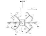
図2は、薬液タンク24からノズル23に至るまでの流路構成を示している。薬液タンク24から排出される薬液は、2つの薬液パイプ36a、36bに分岐して流れる。そして薬液パイプ36aは、薬液ポンプ35aへ到達し、薬液パイプ36bは、薬液ポンプ35bへ到達する。薬液ポンプ35aからホース32が連続して各ノズル23a〜23cへと連続することとなる。また薬液ポンプ35bからホース32が連続して各ノズル23d〜23fへと連続することとなる。
FIG. 2 shows a flow path configuration from the
ここで薬液ポンプ35a、35bは、モーターを動力源としてピストンが往復動することにより薬液を薬液パイプ36a、36bから吸い込み、ホース32ひいては各ノズル23a〜23c、23d〜23fへ吐出する構造のものである。ちなみに薬液ポンプ35a、35bは、制御ユニット15を介して独立に制御可能とされている。例えば薬液ポンプ35aについては制御ユニット15から動作命令が送信され、薬液ポンプ35bについては制御ユニット15から動作命令が送信されなかった場合には、薬液ポンプ35aにつながるノズル23a〜23cのみから薬液が噴射される一方、薬液ポンプ35bにつながるノズル23d〜23fから薬液の噴射を停止するように制御することができる。なお、上述した例では2つの薬液ポンプ35a、35bで構成する場合を例にとり説明をしたが、これに限定されるものではなく、特に比較的小容量の散布の場合等は、薬液ポンプ35を一つのみで構成するようにしてもよい。また大容量の薬液の散布時には、この薬液ポンプ35を3つ以上で構成してもよい。
Here, the chemical pumps 35a and 35b have a structure in which a piston is reciprocated using a motor as a power source to suck the chemical from the
また薬液ポンプ35の吐出力を制御することにより、ノズル23からの薬液の散布量を制御することもできる。即ち、薬液ポンプ35からの薬液の吐出力を弱くすることでノズル23からの薬液の散布量を低くすることができ、薬液ポンプ35からの薬液の吐出力を強くすることでノズル23からの薬液の散布量を増加させることができる。しかも薬液ポンプ35a、35b間で別々にこの吐出力を制御することができるため、ノズル23a〜23cと、ノズル23d〜23fとにつき、互いに独立して散布量を制御することが可能となる。なお、2台の薬液ポンプ35a、35bを用いる場合において、各ノズル23の流量制御装置を省くようにしてもよい。かかる場合には、単純に右側ブーム21及び左側ブーム22毎の吐出量を変える仕組みとする。この構成は機体の左右毎に吐出量を制御するのみだが、各ノズル23の構造を簡略化し、コストを下げることができる。
Further, by controlling the discharge force of the chemical
ノズル23は、上述した右側ブーム21又は左側ブーム22により支持されてなり、接続されたホース32を介して薬液が送られてくる。本実施の形態においては、ノズル23は、23a〜23fの6個に亘り配置される場合を例にとり説明をするがこれに限定されるものではなく、いかなる数に亘り配置されていてもよい。
The
このノズル23は、送られてきた薬液を所定の拡散角度で噴霧する。この薬液の拡散角度と、散布方向の何れか1以上が制御可能とされていてもよい。薬液の拡散角度を変化させる場合には、例えば、拡散角度可変の市販のスプレーノズルを用いるようにしてもよい。また散布方向を変化させる場合には、市販の噴霧方向自在ノズルを用いてもよい。これらの薬液の拡散角度又は散布方向は手動で変更するようにしてもよいが、制御ユニット15による制御の下、電気的な信号に基づいて変更するようにしてもよい。かかる場合には、ノズル23にサーボモーターを組み合わせることにより、電気的な信号に基づいてノズル23の拡散角度や散布方向を自動的に調整することが可能となる。
The
次に制御ユニット15の詳細な構成について説明をする。制御ユニット15は、図3に示すようにフライトコントローラ50を中心とし、これに対してそれぞれ接続されている無線通信部51、電動ジンバル52、カメラ53、ESC(Electronic Speed Controller)54とを備えている。なお、この電動ジンバル52、カメラ53の構成は必須ではなく、省略するようにしてもよい。
Next, a detailed configuration of the
無線通信部51は、操縦端末2との間で無線通信を行う上で必要な周波数変換やその他各種変換処理を行い、電気信号を電波に変換し、或いは電波を電気信号に変換するアンテナも含まれる。この無線通信部51は、操縦端末2から送信されてきた電波に重畳されてきた操縦情報を電気信号に変換した上でフライトコントローラ50へ出力する。その結果、操縦端末2からの操縦情報に基づいたフライトコントローラ50の制御が実現されることとなる。またこの無線通信部51は、フライトコントローラ50から送られてきたデータを電波に変換して操縦端末2に送信する。なお、可能であれば、これらデータをインターネット網等を始めとした公衆通信網へ送信するようにしてもよい。なお、この無線通信部51は、公衆通信網から各種情報を無線通信を通じて取得し、これをフライトコントローラ50へ送信するようにしてもよい。
The
フライトコントローラ50は、制御部57と、この制御部57に接続されている飛行制御センサ群55及びGNSS(Global Navigation Satelite System)受信部56とを備えている。
The
制御部57は、CPU(Central Processing Unit)111と、このCPU111に対してそれぞれ接続されているメモリ112、PWMコントローラ113とを有している。この制御部57は、薬液ポンプ35、ノズル23に接続されている。
The
メモリ112は、ROM(Read Only Memory)やRAM(Random Access Memory)として具現化される記憶手段である。ROMは、制御ユニット15全体のハードウェア資源を制御するためのプログラムが格納されている。またRAMは、データの蓄積や展開等に使用する作業領域として使用され、制御ユニット15全体のハードウェア資源を制御するときの各種命令を一時的に記憶する。
The
CPU111は、全ての構成要素を制御するためのいわゆる中央演算ユニットである。このCPU111は、メモリ112に記憶されているプログラムを読み出して各種動作を行うための命令を各構成要素に対して通知する。例えばメモリ112に記憶されているプログラムが薬液散布用無人航空機1の飛行経路の決定方法や飛行方法に関するものであれば、これに基づいて飛行するための各種命令を静止して各構成要素に送信する。また、メモリ112に記憶されているプログラムが薬液散布用無人航空機1による薬液の散布方法に関するものであれば、これに基づいて薬液を散布するための各種命令を生成して各構成要素に送信する。
The
またCPU111は、無線通信部51から送られてきた操縦情報やその他の情報に基づいて各種命令を生成して各構成要素に送信する。またCPU111は、飛行制御センサ群55から送られてきたデータやGNSS受信部56から送られてきた薬液散布用無人航空機1の現在位置情報に基づいて各構成要素を制御する。さらにCPU111は、接続された薬液ポンプ35、ノズル23を制御するための電気的な信号を生成し、送信する。CPU111は、電動ジンバル52、カメラ53をそれぞれ制御するとともに、PWMコントローラ113に対しても必要な命令を送信する。
In addition, the
PWMコントローラ113は、CPU111による制御の下、ESC54を介してローター用モーター12の回転数、回転速度等を制御する。
The
飛行制御センサ群55は、少なくとも加速度センサ、角速度センサ、気圧センサ(高度センサ)、地磁気センサ(方位センサ)に加え、飛行高度を検出するための高度計、風速や風向を検出するための風向風速計、機体の傾斜角度や傾斜方向を検出するための加速度センサ、ジャイロセンサ等を始めとした各種センサで構成されている。ちなみに飛行制御センサ群55は、これらのセンサが全て実装されている場合に限定されるものではない。例えば加速度センサ、角速度センサから薬液散布用無人航空機1の飛行速度を検知することができる。またジャイロセンサや加速度センサ、角速度センサから薬液散布用無人航空機1の傾き方向や傾き角度を検知することができる。また風向風速計から薬液散布用無人航空機1の飛行時においてその場において吹く風の風向、風速をリアルタイムに検知することが可能となる。高度計から薬液散布用無人航空機1の飛行高度をリアルタイムに検知することが可能となる。飛行制御センサ群55は、検知した各データを制御部57へ送信する。
The flight
GNSS受信部56は、人工衛星から送られてくる衛星測位信号に基づいて薬液散布用無人航空機1の飛行時における現時点の位置情報をリアルタイムに取得する。GNSS受信部56は、取得した位置情報を制御部57へ送信する。
The
電動ジンバル52は、カメラ53が載置される回転台である。この電動ジンバル52は、制御部57におけるCPU111による制御の下で回転自在に構成されている。この電動ジンバル52を回転させることによりカメラ53の撮影方向を変化させることができる。電動ジンバル52は、薬液散布用無人航空機1からの揺動がカメラ53に伝達しないようにするための振動吸収機構が設けられていてもよい。
The
カメラ53は、電動ジンバル52の回転に基づいて定められた撮影方向の被写体を撮像する。カメラ53の撮像タイミングは、CPU111により制御されることとなる。カメラ53は撮影した画像を制御部57へ送信する。この制御部57へ送信された画像は、CPU111による制御の下でメモリ112に記憶される他、必要に応じて無線通信部51を介して公衆通信網へと送られる場合もある。
The
なお上述した構成要素のうち、フライトコントローラ50、電動ジンバル52、カメラ53、ESC54は何れもバッテリー14に接続されており、電力が供給される。
Of the above-described components, the
操縦端末2は、例えばPC(パーソナルコンピューター)、携帯端末、スマートフォン、タブレット型端末、ウェアラブル端末等の無線通信可能な端末装置で構成されているが、これに限定されるものではなく、専用のコントローラーにより具現化されるものであってもよい。操縦端末2は、ユーザが実際に所望の操作を行うためのユーザI/F6と、このユーザI/F6に接続された無線通信部7とを備えている。
The
ユーザI/F6は、薬液散布用無人航空機1を操縦するための操縦情報を入力するためのタッチパネル、ボタン、レバー等で構成されている。またこのユーザI/F6は、ユーザに対して各種情報を表示するための液晶パネル等も含まれる。ユーザI/F6は、入力された操縦情報を無線通信部7へ送信する。またユーザI/F6は、無線通信部7が受信した各種情報が送信された場合には、必要に応じてこれを液晶パネル等を介してユーザに表示する。
The user I /
無線通信部7は、薬液散布用無人航空機1との間で無線通信を行う上で必要な周波数変換やその他各種変換処理を行い、電気信号を電波に変換し、或いは電波を電気信号に変換するアンテナも含まれる。この無線通信部7は、薬液散布用無人航空機1から送信されてきた情報や、公衆通信網から送られてきた情報をユーザI/F6へ出力する。また無線通信部7はユーザI/F6から送られてきた操縦情報を電波に変換し、薬液散布用無人航空機1へ送信する。
The wireless communication unit 7 performs frequency conversion and other various conversion processes necessary for wireless communication with the
次に上述した構成からなる薬液散布用無人航空機1の動作について説明をする。
Next, the operation of the unmanned
先ず薬液散布用無人航空機1は、薬液を散布するための散布対象領域の入力を受け付ける。この散布対象領域は、薬液としての農薬を実施に散布する農作地の地図情報等である。このユーザ自身がこの散布対象領域を入力する場合には、操縦端末2におけるユーザI/F6を介して入力操作を行う。この入力された散布対象領域は、無線通信部7を介して薬液散布用無人航空機1における無線通信部51に送信される。フライトコントローラ50における制御部57は、この散布対象領域を取得し、必要に応じてこれをメモリ112に格納する。
First, the unmanned
次にCPU111は、この散布対象領域に基づく地図情報に対して、実際に飛行計画を策定する。この飛行計画の策定については、メモリ112に記憶された飛行計画策定プログラムを読み出して実行する。なお、飛行計画の策定は、メモリ112からの読み出しに基づく場合に限定されるものではなく、ユーザI/F6からの入力情報に基づくものであってもよい。かかる場合には、ユーザI/F6から飛行計画に関する入力情報を受け付ける都度、この薬液散布用無人航空機1の制御部57へ送信するようにしてもよい。
Next, the
図4は、飛行計画の策定例を示している。CPU111は、取得した散布対象領域71に対して、斜線で示される実際の散布範囲で殆ど埋めることができるような飛行計画を策定する。例えば薬液散布用無人航空機1におけるノズル23から散布される散布領域の幅wは既知であることから、この幅wの散布範囲で散布対象領域71を埋めることができる様々な飛行経路の候補を挙げることができる。この中でも例えば図4の点線で示すような飛行経路のようにジグザグ状に進んでいくことでこれを中心とした幅wの散布範囲により散布対象領域71をカバーすることができる。なお、この飛行計画においては、図4に示すように散布対象領域71の上端又は下端をオーバランした上でUターンして再び散布対象領域71に戻るような経路を設定するようにしてもよい。これにより、散布対象領域71内を隙間無く散布範囲で埋めることができる。ちなみに、このオーバーランした散布対象領域71外の飛行時には、薬液の散布を一時的に停止するようにしてもよい。
FIG. 4 shows an example of formulation of a flight plan. The
また、これ以外に散布対象領域71のほぼ上端又は下端まで到達した場合に特にオーバーランすることなく飛行経路をこの上端、下端の境界に沿って飛行することでUターンするようにしてもよい。
In addition to this, when reaching almost the upper end or the lower end of the
CPU111は、このような飛行経路を設定した後、これに基づいて薬液散布用無人航空機1を飛行させるための制御をPWMコントローラ113に対して行う。PWMコントローラ113は、このCPU111による制御の下でESC54を介してローター用モーター12の回転数、回転速度、回転方向等を制御することにより、図4に示す飛行経路上を飛行させる。
After setting such a flight path, the
また、この飛行経路上を飛行させる過程において制御部57は、薬液ポンプ35に対して動作命令を送信し、ポンプによる薬液の吐出を行わせる。その結果、薬液タンク24に貯留されている薬液は、薬液ポンプ35によりノズル23a〜23fまで送られる。そしてこのノズル23a〜23fに送られた薬液は、散布範囲において散布されることとなる。
Further, in the process of flying on the flight path, the
この薬液の散布の過程で薬液散布用無人航空機1は、飛行経路上を連続して飛行することとなる。これにより、図4に示すように、飛行経路に沿った散布範囲につき薬液を散布することができる。そして、飛行経路の終着点まで飛行することにより、散布対象領域71の大半につき薬液を散布することが可能となる。
In the process of spraying the chemical solution, the unmanned
本発明においては、この飛行経路を飛行する過程において飛行制御センサ群55における加速度センサ、角速度センサ等を介して薬液散布用無人航空機1の飛行速度を検出するようにしてもよい。検出した飛行速度は、制御部57へ送られ、この制御部57は、この飛行速度に基づいて薬液ポンプの吐出力を制御することによりノズル23からの薬液の散布量を制御する。
In the present invention, the flight speed of the unmanned aircraft for spraying
ここで薬液散布用無人航空機1の飛行速度が20km/時で、散布量を1l/秒とすることで、散布対象領域71における単位面積当たりの散布量が適正なものになると仮定する。飛行開始時においてこのような飛行速度、散布量になるように設定をし、例えばP地点において飛行制御センサ群55を介して飛行速度を検出したところ、飛行速度は当初と同様に飛行速度が20km/時であった場合には、特段散布量を変更するための制御は行わない。次にQ地点において測定した飛行速度が25km/時であった場合には、飛行速度が上がっているためその分において単位面積当たりの散布量が低くなってしまう。このため、かかる飛行速度を検知した制御部57は、散布量を1l/秒よりも多くなるように薬液ポンプ35を制御する。次にR地点において測定した飛行速度が15km/時であった場合には、飛行速度が遅くなっているためその分において単位面積当たりの散布量が高くなってしまう。このため、かかる飛行速度を検知した制御部57は、散布量を1l/秒よりも低くなるように薬液ポンプ35を制御する。
Here, it is assumed that the spray rate per unit area in the
このようにして本発明では、検出した飛行速度に基づいて薬液タンク14に貯留されている薬液の散布量を制御する。これにより、散布対象領域71内の農作地における単位面積当たりの薬液の散布量を均一に調整することができる。その結果、薬液の散布量にムラが生じるのを防止でき、薬液の散布量が多すぎることによる農薬焼けや、薬液の散布量が少なすぎることによる農作物の病気や害虫被害を防止することが可能となる。
Thus, in the present invention, the spray amount of the chemical liquid stored in the
特に薬液散布用無人航空機1の飛行速度を一定になるように設定しても、突発的な風や周辺環境の変化、或いは薬液散布用無人航空機1の各構成要素に起因して、飛行速度が必ずしも一定にならず、僅かな範囲でブレてしまうことがある。かかる場合においても飛行速度の変化をリアルタイムに検知し、これに基づいて散布量を調整することで、結果としては薬液の散布量にムラが生じるのを防止できる。
In particular, even if the flight speed of the unmanned aircraft for spraying
なお、上述した実施の形態においては、P地点〜R地点の3箇所に亘り飛行速度を検知する場合を例にとり説明をしたが、これに限定されるものではなく、更に短いピッチで飛行速度を検出するようにしてもよい。かかる場合には、例えば毎秒に亘り飛行速度を検知し、散布量の制御もこれに応じて毎秒行うようにしてもよい。 In the embodiment described above, the case where the flight speed is detected at three points from the P point to the R point has been described as an example. However, the present invention is not limited to this, and the flight speed is set at a shorter pitch. You may make it detect. In such a case, for example, the flight speed may be detected every second, and the amount of spraying may be controlled every second accordingly.
なお、図5に示すような散布対象領域71の端部72について薬液を散布する際には、飛行速度をあえて遅くさせると有効な場合がある。このように散布対象領域71内における位置に応じて飛行速度を速める場合もあれば遅くする場合もある。かかる場合には、散布対象領域71内における現時点の位置情報をGNSS受信部56を介してリアルタイムに受信し、制御部57は、その受信した位置情報の散布対象領域71との関係に基づいて飛行速度を制御するようにしてもよい。散布対象領域71は、地図情報として予め取得していることから、これに対して受信した位置情報を重ね合わせることにより、薬液散布用無人航空機1が現時点において散布対象領域71上のどの位置を飛行しているかをリアルタイムに検知することが可能となる。制御部57は、係る情報に基づいて飛行速度を制御することとなる。
In addition, when spraying a chemical | medical solution about the
また、薬液散布用無人航空機1が現時点において散布対象領域71上のどの位置を飛行しているかをリアルタイムに検知した結果を利用し、散布量を直接制御するようにしてもよいし、散布範囲を制御するようにしてもよい。散布量の制御方法は上述したとおりであるが、散布範囲を制御する際には、例えば図6に示すようにノズル23d〜23fのみから薬液を噴射させ、ノズル23a〜23cからは薬液の噴射を停止するように制御する。これらの制御は、上述したように制御ユニット15から薬液ポンプ35a、35bに動作命令を発信することで実現する。制御ユニット15は、散布対象領域71上のどの位置を飛行しているかをリアルタイムに検知しているため、ちょうど散布対象領域71の端部を飛行している旨を判別した場合には、散布対象領域71上に位置するノズル23d〜23fのみから薬液を噴射させることで農作物に薬液を散布させることができる。また散布対象領域71から外れるノズル23a〜23cからは薬液の噴射を停止することで、散布対象領域71外に薬液が散布されることによる被害を防止できる。
Further, the spray amount may be controlled directly using the result of detecting in real time which position on the
また、本発明によれば、検出した飛行高度に基づいて薬液の散布量を制御するようにしてもよい。かかる場合には、飛行制御センサ群55における高度計等を介して薬液散布用無人航空機1の飛行高度を検出するようにしてもよい。検出した飛行高度は、制御部57へ送られ、この制御部57は、この飛行高度に基づいて薬液ポンプの吐出力を制御することによりノズル23からの薬液の散布量をリアルタイムに制御する。
Further, according to the present invention, the spray amount of the chemical solution may be controlled based on the detected flight altitude. In such a case, the flight altitude of the unmanned aircraft for spraying
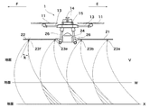
図7は、各飛行高度V〜Wにおける地面における薬液の散布範囲の関係を模式的に示している。薬液散布用無人航空機1が飛行高度Wである場合に、薬液の散布範囲が重なることなく、薬液が散布されていない非散布領域が形成されることなく、単位面積当たりの散布濃度をほぼ均一にすることができる。これに対して、飛行高度Vである場合には、飛行高度が低すぎてしまい、薬液の散布範囲が広がる前に地面に到達してしまう。その結果、散布対象領域71において非散布領域が形成されてしまう。一方、飛行高度Zである場合には、飛行高度が高すぎてしまい、隣接するノズル23から散布された薬液の散布範囲が重なってしまう。
FIG. 7 schematically shows the relationship of the spraying range of the chemical solution on the ground at each flight altitude V to W. When the unmanned
即ち、飛行高度V、Zでは、地面に対する薬液散布用無人航空機1が飛行高度が適切な高さとされていないため、単位面積当たりの薬液散布量にムラが生じてしまう。このため、本発明では、薬液散布用無人航空機1の飛行高度を測定し、これが飛行高度Wの如く適切な高さであれば、特段新たな制御を行う必要は無い。これに対して飛行高度がVであれば図8(a)に示すように各ノズル23からの薬液の散布角度を広くするように制御する。具体的には、制御部57は、飛行制御センサ群55から検知した飛行高度が飛行高度Vであることを判別し、これに基づいてノズル23に対して電気信号を送ることにより拡散角度を拡げるように制御する。その結果、ノズル23から出射された薬液はより拡がるようにして地面に散布される結果、非散布領域をより狭くすることが可能となる。これに対して飛行高度がZであれば図8(b)に示すように各ノズル23からの薬液の散布角度を狭くするように制御する。具体的には、制御部57は、飛行制御センサ群55から検知した飛行高度が飛行高度Zであることを判別し、これに基づいてノズル23に対して電気信号を送ることにより拡散角度を狭めるように制御する。その結果、ノズル23から出射された薬液はより狭められて地面に散布される結果、散布範囲の重なりをより狭くすることが可能となる。
That is, at the flight altitudes V and Z, the unmanned
ちなみに、制御部57は、飛行高度を判別した場合において、上述したノズル23からの散布角度の調整以外に、散布量を調整するようにしてもよい。例えば高度が低い飛行高度Vの場合には、散布量を多くすることで非散布領域にも薬液が行き渡るようにし、高度が高い飛行高度Zの場合には、散布量を少なくすることで散布範囲の重なり部分において散布濃度が極端に高くなるのを防止することが可能となる。なお、本発明において、散布角度及び散布量の何れか1以上を調整するものであればよい。
Incidentally, the
また制御ユニット15は、散布対象領域71上のどの位置を飛行しているかをGNSS受信部56を介してリアルタイムに検知しているため、図9に示すように散布対象領域71の端部を飛行している旨を判別した場合には、ノズル23からの薬液の拡散角度を調整するようにしてもよい。このとき、ノズル23からの薬液の拡散角度を広く設定した場合に散布対象領域71外に薬液が散布されてしまう場合には、その薬液の拡散角度を狭くするようにしてもよい。また、薬液の拡散角度を広くすることで散布対象領域71の残部を含めて全て散布範囲で埋めることができる場合には、ノズル23からの拡散角度を広く設定するようにしてもよい。このとき、拡散角度のみならず、散布角度及び散布量の何れか1以上を制御するようにしてもよい。
Further, since the
また、本発明によれば、検出した風向、風速の何れか1以上に基づいて薬液方向を変化させるようにしてもよい。かかる場合には、飛行制御センサ群55における風向風速計等を介して薬液散布用無人航空機1の風向や風速を検出するようにしてもよい。検出した風向、風速は、制御部57へ送られ、この制御部57は、この風向、風速に基づいてノズル23の散布方向をリアルタイムに制御する。
According to the present invention, the direction of the chemical solution may be changed based on one or more of the detected wind direction and wind speed. In such a case, the wind direction and wind speed of the unmanned aircraft for spraying
例えば図10に示すように薬液散布用無人航空機1に対して風向Eの風が吹いた場合、ノズル23から出射した薬液は風向Eの方向に向けて流されることとなる。その結果、各飛行高度V〜Xの地面に着地する薬液の散布範囲は風向Eに向けて大きく偏ることとなる。図11は、この薬液散布用無人航空機1を真上から視認した状態を示す平面図である。ノズル23から放たれている薬液を示す図中実線は、散布直後の薬液の拡がりを示しており、図中点線は、飛行高度Wの地面に接する直前の薬液の拡がりを示している。薬液の散布範囲は、風向に応じて意図している範囲から大きく逸脱することが示されている。
For example, as shown in FIG. 10, when a wind in the wind direction E blows against the
このため、本発明によれば、飛行制御センサ群55における風向風速計等により風向や風速を検出し、制御部57は、この検出した風向や風速に基づいてノズル23に対して電気信号を送ることにより散布方向を変化させるように制御する。
Therefore, according to the present invention, the wind direction and wind speed are detected by the wind direction anemometer or the like in the flight
図12の例は、薬液の散布方向を風向Eと反対方向のF方向に変化させた例を示している。薬液の散布方向をF方向に傾けることで風向Eによる影響を受けた場合においても結局は相殺されて意図している散布範囲から大きく逸脱することを防止できる。実際にF方向に向けてどの程度ノズル23を傾けるかは、検出した風速に基づいて決定するようにしてもよい。即ち、風向Eの風速が大きい場合には、これに強固に対抗するためにノズル23のF方向への傾き角度kを大きくする。これに対して、風向Eの風速が小さい場合には、ノズル23のF方向への傾き角度kを小さくする。
The example of FIG. 12 shows an example in which the spraying direction of the chemical liquid is changed in the F direction opposite to the wind direction E. By tilting the spraying direction of the chemical solution in the F direction, even if it is affected by the wind direction E, it is possible to prevent it from being canceled out and deviating greatly from the intended spraying range. How much the
なお、このノズル23による薬液の散布方向を変化させる過程で、検知した飛行高度に応じて異ならせるようにしてもよい。かかる場合には、飛行高度V〜Xに応じて最適な散布角度となるように設定を行う。このとき、拡散角度や散布量も一緒に調整するようにしてもよい。
Note that, in the process of changing the spray direction of the chemical solution by the
また、ノズル23による薬液の散布方向を変化させる場合は、風向や風速に基づく場合に限定されるものではない。例えば散布対象領域71上のどの位置を飛行しているかをリアルタイムに検知した結果を利用し、散布方向を直接制御するようにしてもよい。例えば散布対象領域71の端部近傍を飛行していることを識別した場合、薬液が散布対象領域71外に逸脱しないようにするため、薬液の散布方向を内側に調整することをリアルタイムで実行するようにしてもよい。
Moreover, when changing the spray direction of the chemical | medical solution by the
また、本発明によれば、検知した風速、風向に基づいて飛行経路を制御するようにしてもよい。例えば薬液散布用無人航空機1を図13に示す矢印の方向に飛行させる過程で、風向、風速を随時検知する。G地点において検知した風向、風速がともに0である場合には、飛行経路は特段の制御を行うことなく、同様に図中矢印の方向に向けて飛行をし続ける。ここでH地点において風向がE方向であり風速が2m/sであることを判別した場合には、これに対抗するために、E方向と正反対方向であるF方向に向けて飛行方向を変更させるための制御を行う。図中の飛行方向の変更方向のベクトルの大きさは、F方向に向けた推進力の大きさに対応している。この推進力の大きさは、測定した風速に基づいてバランスが調整され、当初意図していた飛行経路上のH´を通過することとなる。同様にI地点において風向がE方向であり風速が5m/sであることを判別した場合には、これに対抗するために、E方向と正反対方向であるF方向に向けて飛行方向を変更させ、そのF方向への推進力もこれに応じて大きく調整する。これにより当初意図していた飛行経路上のI´を通過することとなる。
Further, according to the present invention, the flight path may be controlled based on the detected wind speed and direction. For example, in the process of flying the unmanned aircraft for spraying
その結果、薬液散布用無人航空機1は、飛行途中において突発的に大きな風が吹いた場合においても、この風向、風速をリアルタイムに検知し、これに応じて飛行方向を変更することにより、当初意図したとおりの図中点線矢印方向の経路を辿ることが可能となる。
As a result, the unmanned
なお、風速の上限値を予め設定しておき、測定した風速がその上限値を超えた場合には、薬液の散布を停止すると共にその場でホバリングするようにしてもよい。 Note that an upper limit value of the wind speed may be set in advance, and when the measured wind speed exceeds the upper limit value, spraying of the chemical solution may be stopped and hovered on the spot.
この経路変更においては、更に図14に示すように散布対象領域71における薬液散布用無人航空機1の現在位置を参照するようにしてもよい。例えば取得した地図情報から、散布対象領域71の端部が複雑な形状をしている場合においても、これに沿って薬液散布用無人航空機1の飛行経路を変更するようにしてもよい。かかる場合には、散布対象領域71との関係において、薬液散布用無人航空機1がJ地点に位置していることを識別した場合には、事前の地図情報から散布対象領域71の端部が内側に入り込んでいることが分かっているため、これに沿って内側に飛行経路を変更する。そして、その散布対象領域71の端部に沿って曲線を描くように飛行し、K地点まで到達したことを飛行制御センサ群55を介して判別した場合には、再び矢印の方向に向けて直進するように制御する。
In this route change, as shown in FIG. 14, the current position of the
なお、上述した各制御では、飛行速度、飛行高度、風向、風速に対して、散布量、拡散角度、飛行経路、散布方向等をどの程度制御すれば最適になるかを事前の実験的検討やシミュレーションを通じてデータを取得しておき、その取得したデータを参照して実際の制御量を決定するようにしてもよい。 In addition, in each control described above, it is possible to conduct an experimental study in advance to determine how much the spray amount, diffusion angle, flight path, spray direction, etc. are controlled with respect to the flight speed, flight altitude, wind direction, and wind speed. Data may be acquired through simulation, and the actual control amount may be determined with reference to the acquired data.
また、本発明は、飛行経路上を飛行する時における薬液散布用無人航空機1の機体の傾斜角度及び傾斜方向に基づいて風向及び風速を検知するようにしてもよい。傾斜角度、傾斜方向は、飛行制御センサ群55におけるデジタル水準器等を利用する。
Further, in the present invention, the wind direction and the wind speed may be detected based on the inclination angle and the inclination direction of the airframe of the unmanned
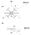
図15(a)は、飛行方向Fwに向けて飛行していた薬液散布用無人航空機1が飛行方向Fwに向けて飛行する際において風向Wdの風が吹いた状態を示す平面図である。このような風向Wdの風を受けた薬液散布用無人航空機1は、当該風向Wdに向けて図中下向きに傾くこととなる。飛行方向Fwに対する風向Wdの角度を角度θという。
FIG. 15A is a plan view showing a state in which the wind in the wind direction Wd is blown when the unmanned aircraft for spraying
図15(b)は、風向Wdの延長線上Lsの断面構成を示している。図15(b)では、薬液散布用無人航空機1における各構成要素のうち、簡単のため制御ユニット15のみを代表して描いている。この制御ユニット15は、通常は断面視で、実線で示すようにほぼ水平になるようにして飛行することとなるが、風向Wdの風に対して、点線に示すように前かがみになるように傾くこととなる。風に対するこの前かがみになる傾き角を角度φという。風速が強いほど風向Wdに対して薬液散布用無人航空機1は前傾姿勢となる。つまり角度φは風速に依存する。薬液散布用無人航空機1は、ホバリングしている場合において風向Wdに対して前傾姿勢となって流されることを回避するが、この姿勢の変化を利用して逆に風向Wdと風速を検知する。
FIG. 15B shows a cross-sectional configuration on the extension line Ls of the wind direction Wd. In FIG. 15 (b), only the
つまり、平面視でどの方向に傾くかを識別することで角度θを判別することができ、この角度θから風向Wdを判別することが可能となる。断面視での角度φを判別することで、風速を判別することが可能となる。 That is, the angle θ can be determined by identifying which direction the plane is inclined in a plan view, and the wind direction Wd can be determined from the angle θ. By determining the angle φ in cross-sectional view, it is possible to determine the wind speed.
断面視での角度φに対する風速の対応関係を、薬液散布用無人航空機1の機種毎に予めシミュレーションや実験を通じて予め対応表等によりデータ化しておく。実際に薬液散布用無人航空機1を飛行させる段階において、この対応表を参照することで、検知した角度φから風速を判別するようにしてもよい。この角度θ、角度φの検知は、飛行制御センサ群55を介して高精度に検出することができる。このため角度θ、角度φから、風向Wd、風速を高精度に検知することが可能となる。
The correspondence relationship of the wind speed with respect to the angle φ in the cross-sectional view is previously converted into data by a correspondence table or the like through simulation or experiment in advance for each model of the unmanned aircraft for spraying chemical liquid. The actual wind speed may be determined from the detected angle φ by referring to this correspondence table at the stage of actually flying the
特に薬液散布用無人航空機1は、ローター11の回転により生成する風が複雑な気流と気圧変化をもたらしている場合が多い。しかしながら、角度θ、角度φを検知する上でこのような気流と気圧の影響は殆ど受けないため、より高精度な風向Wd、風速の測定を行うことが可能となる。
In particular, the unmanned
1 薬液散布用無人航空機
2 操縦端末
6 ユーザI/F
7 無線通信部
11 ローター
12 ローター用モーター
13 モーターステイ
14 バッテリー
15 制御ユニット
16 第1中央プレート
17 第2中央プレート
18 第3中央プレート
20 据付器具
21 右側ブーム
22 左側ブーム
23 ノズル
24 薬液タンク
26 脚部
27 載置用アーム
28 スキッド
32 ホース
35 薬液ポンプ
35 薬液ポンプ
36 薬液パイプ
50 フライトコントローラ
51 無線通信部
52 電動ジンバル
53 カメラ
54 ESC
55 飛行制御センサ群
56 GNSS受信部
57 制御部
71 散布対象領域
72 端部
112 メモリ
113 PWMコントローラ
1 Unmanned aerial vehicle for spraying
7
55 Flight
Claims (9)
上記散布対象領域に対して設定された飛行経路上を飛行するように制御する飛行制御手段と、
上記飛行経路の飛行時における飛行速度を検出する飛行速度検出手段と、
上記飛行速度検出手段により検出された飛行速度に基づいて、上記薬液タンクに貯留されている薬液の散布量を制御する散布制御手段とを備えること
を特徴とする薬液散布用無人航空機。 In the unmanned aircraft for spraying chemicals that sprays the chemicals stored in the chemical tank to the spray target area input in advance,
Flight control means for controlling to fly on the flight path set for the scattering target area;
Flight speed detection means for detecting the flight speed during flight of the flight path;
An unmanned aerial vehicle for spraying chemical liquid, comprising: spray control means for controlling a spray amount of the chemical liquid stored in the chemical liquid tank based on the flight speed detected by the flight speed detection means.
上記飛行制御手段は、上記位置情報取得手段により取得された位置情報の上記散布対象領域との関係に基づいて飛行速度を制御すること
を特徴とする請求項1記載の薬液散布用無人航空機。 It further comprises position information acquisition means for acquiring each position information in flight on the flight path in real time,
The unmanned aerial vehicle for spraying chemicals according to claim 1, wherein the flight control unit controls the flight speed based on a relationship between the position information acquired by the position information acquiring unit and the region to be sprayed.
上記散布対象領域に対して設定された飛行経路上を飛行するように制御する飛行制御手段と、
上記飛行経路の飛行時における各位置情報をリアルタイムで取得する位置情報取得手段と、
上記薬液タンクに貯留されている薬液を複数の散布口を介して散布可能な散布制御手段とを備え、
上記位置情報取得手段により取得された位置情報の上記散布対象領域との関係に基づいて、上記複数の散布口のうち何れか1以上を閉口させること
を特徴とする薬液散布用無人航空機。 In the unmanned aircraft for spraying chemicals that sprays the chemicals stored in the chemical tank to the spray target area input in advance,
Flight control means for controlling to fly on the flight path set for the scattering target area;
Position information acquisition means for acquiring each position information at the time of flight of the flight path in real time;
A spray control means capable of spraying the chemical liquid stored in the chemical liquid tank through a plurality of spray ports;
An unmanned aerial vehicle for spraying chemicals, wherein one or more of the plurality of spray ports are closed based on the relationship between the position information acquired by the position information acquisition unit and the region to be sprayed.
上記散布対象領域に対して設定された飛行経路上を飛行するように制御する飛行制御手段と、
上記飛行経路の飛行時における飛行高度を検出する飛行高度検出手段と、
上記飛行高度検出手段により検出された飛行高度に基づいて、上記薬液タンクに貯留されている薬液の散布量並びにその薬液の拡散角度の何れか1以上を制御する散布制御手段とを備えること
を特徴とする薬液散布用無人航空機。 In the unmanned aircraft for spraying chemicals that sprays the chemicals stored in the chemical tank against the spray target area input in advance,
Flight control means for controlling to fly on the flight path set for the scattering target area;
A flight altitude detecting means for detecting a flight altitude during the flight of the flight path;
And a spray control means for controlling one or more of the spray amount of the chemical liquid stored in the chemical liquid tank and the diffusion angle of the chemical liquid based on the flight altitude detected by the flight altitude detecting means. An unmanned aircraft for spraying chemicals.
上記散布制御手段は、上記位置情報取得手段により取得された位置情報の上記散布対象領域との関係に基づいて、上記薬液タンクに貯留されている薬液の散布量並びにその薬液の拡散角度の何れか1以上を制御すること
を特徴とする請求項4記載の薬液散布用無人航空機。 It further comprises position information acquisition means for acquiring each position information in flight on the flight path in real time,
The spray control means is either a spray amount of the chemical liquid stored in the chemical liquid tank or a diffusion angle of the chemical liquid based on the relationship between the position information acquired by the position information acquisition means and the region to be sprayed. The unmanned aerial vehicle for spraying chemicals according to claim 4, wherein one or more are controlled.
上記散布対象領域に対して設定された飛行経路上を飛行するように制御する飛行制御手段と、
上記飛行経路の飛行時における風向及び風速をリアルタイムに検出する風検知手段と、
上記風検知手段により検知された風向及び風速に基づいて、上記薬液の散布方向を、上記飛行経路を飛行する過程で変化させる散布制御手段とを備えること
を特徴とする薬液散布用無人航空機。 In the unmanned aircraft for spraying chemicals that sprays the chemicals stored in the chemical tank to the spray target area input in advance,
Flight control means for controlling to fly on the flight path set for the scattering target area;
Wind detection means for detecting in real time the wind direction and wind speed during flight of the flight path;
An unmanned aerial vehicle for spraying chemical liquid, comprising: spray control means for changing a spray direction of the chemical liquid in a process of flying the flight path based on a wind direction and a wind speed detected by the wind detection means.
上記散布制御手段は、更に上記位置情報取得手段により取得された位置情報の上記散布対象領域との関係に基づいて上記薬液の散布方向を変化させること
を特徴とする請求項6記載の薬液散布用無人航空機。 It further comprises position information acquisition means for acquiring each position information in flight on the flight path in real time,
The chemical spraying means according to claim 6, wherein the spraying control means further changes the spraying direction of the chemical liquid based on the relationship between the position information acquired by the position information acquisition means and the spray target area. Unmanned aerial vehicle.
上記散布対象領域に対して設定された飛行経路上を飛行するように制御する飛行制御手段と、
上記飛行経路の飛行時における風向及び風速をリアルタイムに検出する風検知手段とを備え、
上記飛行制御手段は、上記風検知手段により検知された風向及び風速に基づいて、上記飛行経路を切り替えること
を特徴とする薬液散布用無人航空機。 In the unmanned aircraft for spraying chemicals that sprays the chemicals stored in the chemical tank to the spray target area input in advance,
Flight control means for controlling to fly on the flight path set for the scattering target area;
Wind detection means for detecting in real time the wind direction and wind speed during flight of the flight path,
The unmanned aircraft for spraying chemical liquid, wherein the flight control means switches the flight path based on a wind direction and a wind speed detected by the wind detection means.
を特徴とする請求項6〜8のうち何れか1項記載の薬液散布用無人航空機。 The said wind detection means detects the said wind direction and the said wind speed based on the inclination angle and inclination direction of an airframe when flying on the said flight path, The any one of Claims 6-8 characterized by the above-mentioned. Unmanned aerial vehicle for spraying chemicals.
Priority Applications (1)
| Application Number | Priority Date | Filing Date | Title |
|---|---|---|---|
| JP2016098246A JP2017206066A (en) | 2016-05-16 | 2016-05-16 | Unmanned aircraft for spraying chemical solution |
Applications Claiming Priority (1)
| Application Number | Priority Date | Filing Date | Title |
|---|---|---|---|
| JP2016098246A JP2017206066A (en) | 2016-05-16 | 2016-05-16 | Unmanned aircraft for spraying chemical solution |
Related Child Applications (1)
| Application Number | Title | Priority Date | Filing Date |
|---|---|---|---|
| JP2021011213A Division JP2021075277A (en) | 2021-01-27 | 2021-01-27 | Unmanned aircraft for spreading chemical liquid |
Publications (1)
| Publication Number | Publication Date |
|---|---|
| JP2017206066A true JP2017206066A (en) | 2017-11-24 |
Family
ID=60414658
Family Applications (1)
| Application Number | Title | Priority Date | Filing Date |
|---|---|---|---|
| JP2016098246A Pending JP2017206066A (en) | 2016-05-16 | 2016-05-16 | Unmanned aircraft for spraying chemical solution |
Country Status (1)
| Country | Link |
|---|---|
| JP (1) | JP2017206066A (en) |
Cited By (44)
| Publication number | Priority date | Publication date | Assignee | Title |
|---|---|---|---|---|
| CN108279596A (en) * | 2018-01-22 | 2018-07-13 | 北京蜂巢农科科技有限责任公司 | Unmanned plane chemicals dosing plant and unmanned plane adding method thereof |
| CN108402021A (en) * | 2018-06-14 | 2018-08-17 | 华南农业大学 | A kind of agricultural plant protection unmanned plane sprinkling system compensated automatically with droplet drift detection |
| CN108508809A (en) * | 2018-04-28 | 2018-09-07 | 山西农业大学 | A kind of brainpower insufflation system and method based on plant protection drone pressure type nozzle |
| CN108583899A (en) * | 2018-05-16 | 2018-09-28 | 杭州电子科技大学 | A kind of novel spray structure on unmanned plane propeller |
| CN109757459A (en) * | 2019-02-22 | 2019-05-17 | 农业农村部南京农业机械化研究所 | A kind of plant protection unmanned aerial vehicle mist droplet particle size and discharge rate regulation device and method |
| CN109774943A (en) * | 2019-02-27 | 2019-05-21 | 广州极飞科技有限公司 | Broadcast sowing method of adjustment, device, unmanned plane and the storage medium of dosage |
| WO2019119239A1 (en) * | 2017-12-18 | 2019-06-27 | 深圳市大疆创新科技有限公司 | Method and device for measuring spray area |
| JP2019111871A (en) * | 2017-12-21 | 2019-07-11 | 株式会社クボタ | Agricultural multicopter |
| JP2019123415A (en) * | 2018-01-18 | 2019-07-25 | 株式会社プロドローン | Unmanned aircraft for aero spraying, external device, control program and aero spraying method |
| JP2019127084A (en) * | 2018-01-23 | 2019-08-01 | 株式会社フジタ | Spraying flight device |
| WO2019168047A1 (en) * | 2018-02-28 | 2019-09-06 | 株式会社ナイルワークス | Drone, drone control method, and drone control program |
| WO2019168045A1 (en) * | 2018-02-28 | 2019-09-06 | 株式会社ナイルワークス | Drone, control method thereof, and program |
| CN110217397A (en) * | 2019-07-09 | 2019-09-10 | 农业农村部南京农业机械化研究所 | A kind of anti-spraying mechanism that floats of plant protection unmanned aerial vehicle |
| WO2019189929A1 (en) * | 2018-03-30 | 2019-10-03 | 株式会社ナイルワークス | Chemical spray drone |
| WO2019208607A1 (en) * | 2018-04-25 | 2019-10-31 | 株式会社ナイルワークス | System, method, and computer program for preventing leakage of chemicals |
| WO2019208608A1 (en) * | 2018-04-25 | 2019-10-31 | 株式会社ナイルワークス | System, method, and computer program for failure detection |
| WO2020022264A1 (en) * | 2018-07-23 | 2020-01-30 | 株式会社ナイルワークス | Flying body |
| CN110859172A (en) * | 2019-12-19 | 2020-03-06 | 广州极飞科技有限公司 | Spraying system and control method of spraying system |
| CN110901921A (en) * | 2019-12-03 | 2020-03-24 | 华南农业大学 | Air curtain type spraying anti-drifting device and method for plant protection unmanned aerial vehicle |
| WO2020075868A1 (en) * | 2018-10-12 | 2020-04-16 | 株式会社ナイルワークス | Cultivated field image analysis method |
| WO2020085239A1 (en) * | 2018-10-23 | 2020-04-30 | 株式会社ナイルワークス | Operation route generation device, operation route generation method, operation route generation program, and drone |
| CN111221351A (en) * | 2020-01-19 | 2020-06-02 | 西安科技大学 | Method for flying materials by centrifugal unmanned aerial vehicle |
| WO2020137554A1 (en) * | 2018-12-27 | 2020-07-02 | 株式会社ナイルワークス | Drone, method of controlling drone, and drone control program |
| CN111459183A (en) * | 2020-04-10 | 2020-07-28 | 广州极飞科技有限公司 | Operation parameter recommendation method and device, unmanned equipment and storage medium |
| KR102140178B1 (en) * | 2019-02-19 | 2020-07-31 | 전북대학교산학협력단 | Agricultural drone having function of preventing drift |
| CN111516876A (en) * | 2020-04-29 | 2020-08-11 | 莆田市信田农业科技有限公司 | Plant protection unmanned aerial vehicle and liquid medicine spraying control method thereof |
| WO2020179460A1 (en) * | 2019-03-06 | 2020-09-10 | ソニー株式会社 | Control device, control method, and program |
| JPWO2019172061A1 (en) * | 2018-03-07 | 2020-12-03 | 株式会社ナイルワークス | Unmanned aerial vehicle, mobile |
| WO2021056457A1 (en) * | 2019-09-27 | 2021-04-01 | 深圳市大疆创新科技有限公司 | Pump assembly, spraying system, mobile device, and spraying method for mobile device |
| JP2021054280A (en) * | 2019-09-30 | 2021-04-08 | 株式会社ナイルワークス | Operation route generation system, operation route generation method, operation route generation program, and drone |
| JP2021058866A (en) * | 2019-10-09 | 2021-04-15 | ソフトバンク株式会社 | Injection device, program, system, and injection method |
| WO2021071067A1 (en) * | 2019-10-08 | 2021-04-15 | 전북대학교산학협력단 | Agricultural drone having spray nozzles mounted therein |
| CN112805649A (en) * | 2020-04-26 | 2021-05-14 | 深圳市大疆创新科技有限公司 | Spray evaluation method, apparatus and storage medium |
| WO2021100501A1 (en) * | 2019-11-19 | 2021-05-27 | 東洋製罐株式会社 | Takeoff and landing platform, method for using takeoff and landing platform, and program |
| WO2021140657A1 (en) * | 2020-01-10 | 2021-07-15 | 株式会社ナイルワークス | Drone system, flight management device, and drone |
| WO2021166175A1 (en) * | 2020-02-20 | 2021-08-26 | 株式会社ナイルワークス | Drone system, controller, and method for defining work area |
| CN113329941A (en) * | 2019-01-21 | 2021-08-31 | 拜耳公司 | Aircraft with a flight control device |
| CN113716016A (en) * | 2021-09-02 | 2021-11-30 | 江苏网智无人机研究院有限公司 | Agricultural plant protection unmanned aerial vehicle convenient to control flight gesture |
| JP2022506024A (en) * | 2018-10-31 | 2022-01-17 | フォルテム テクノロジーズ,インコーポレイテッド | Systems and methods for managing projectile modules on flight devices |
| WO2022095062A1 (en) * | 2020-11-09 | 2022-05-12 | 深圳市大疆创新科技有限公司 | Method and apparatus for planning route for unmanned aerial vehicle, and device and unmanned aerial vehicle |
| WO2022166180A1 (en) * | 2021-02-05 | 2022-08-11 | 海南天然橡胶产业集团股份有限公司 | Rapidly replaceable unmanned aerial vehicle pesticide box for use in rubber forest |
| RU216314U1 (en) * | 2022-11-12 | 2023-01-30 | Общество с ограниченной ответственностью "ЧИСТОЕ НЕБО" | Unmanned hang-glider |
| EP4005684A4 (en) * | 2019-07-23 | 2023-07-26 | Toyo Seikan Co., Ltd. | Unmanned aerial vehicle |
| KR20240047719A (en) | 2022-10-05 | 2024-04-12 | 주식회사 현대케피코 | Method for Preventing from Disaster Spray Automatic Control using Drone and Drone therefor |
Citations (8)
| Publication number | Priority date | Publication date | Assignee | Title |
|---|---|---|---|---|
| JPH10337146A (en) * | 1997-06-09 | 1998-12-22 | Yamaha Motor Co Ltd | System for spraying pesticide |
| JPH11138071A (en) * | 1997-11-12 | 1999-05-25 | New Delta Ind Co | Chemical spraying apparatus mounted on radio control type helicopter |
| JP2001120151A (en) * | 1999-10-27 | 2001-05-08 | Nec Corp | Automatic agrochemical spraying device with radio controlled helicopter using gps |
| JP2006176073A (en) * | 2004-12-24 | 2006-07-06 | Fuji Heavy Ind Ltd | Chemical spraying system using unmanned helicopter |
| JP2007030544A (en) * | 2005-07-22 | 2007-02-08 | Yanmar Agricult Equip Co Ltd | Aerial spray device |
| US20070145191A1 (en) * | 2005-03-17 | 2007-06-28 | Smith David B | Method and system for increasing safety in chemical application from an aircraft |
| JP2007290647A (en) * | 2006-04-27 | 2007-11-08 | Yamaha Motor Co Ltd | Unmanned helicopter and external environment estimating device |
| JP2009269493A (en) * | 2008-05-08 | 2009-11-19 | Yamaha Motor Co Ltd | Unmanned helicopter |
-
2016
- 2016-05-16 JP JP2016098246A patent/JP2017206066A/en active Pending
Patent Citations (8)
| Publication number | Priority date | Publication date | Assignee | Title |
|---|---|---|---|---|
| JPH10337146A (en) * | 1997-06-09 | 1998-12-22 | Yamaha Motor Co Ltd | System for spraying pesticide |
| JPH11138071A (en) * | 1997-11-12 | 1999-05-25 | New Delta Ind Co | Chemical spraying apparatus mounted on radio control type helicopter |
| JP2001120151A (en) * | 1999-10-27 | 2001-05-08 | Nec Corp | Automatic agrochemical spraying device with radio controlled helicopter using gps |
| JP2006176073A (en) * | 2004-12-24 | 2006-07-06 | Fuji Heavy Ind Ltd | Chemical spraying system using unmanned helicopter |
| US20070145191A1 (en) * | 2005-03-17 | 2007-06-28 | Smith David B | Method and system for increasing safety in chemical application from an aircraft |
| JP2007030544A (en) * | 2005-07-22 | 2007-02-08 | Yanmar Agricult Equip Co Ltd | Aerial spray device |
| JP2007290647A (en) * | 2006-04-27 | 2007-11-08 | Yamaha Motor Co Ltd | Unmanned helicopter and external environment estimating device |
| JP2009269493A (en) * | 2008-05-08 | 2009-11-19 | Yamaha Motor Co Ltd | Unmanned helicopter |
Cited By (67)
| Publication number | Priority date | Publication date | Assignee | Title |
|---|---|---|---|---|
| WO2019119239A1 (en) * | 2017-12-18 | 2019-06-27 | 深圳市大疆创新科技有限公司 | Method and device for measuring spray area |
| JP2019111871A (en) * | 2017-12-21 | 2019-07-11 | 株式会社クボタ | Agricultural multicopter |
| JP2019123415A (en) * | 2018-01-18 | 2019-07-25 | 株式会社プロドローン | Unmanned aircraft for aero spraying, external device, control program and aero spraying method |
| CN108279596A (en) * | 2018-01-22 | 2018-07-13 | 北京蜂巢农科科技有限责任公司 | Unmanned plane chemicals dosing plant and unmanned plane adding method thereof |
| JP2019127084A (en) * | 2018-01-23 | 2019-08-01 | 株式会社フジタ | Spraying flight device |
| JP7011474B2 (en) | 2018-01-23 | 2022-01-26 | 株式会社フジタ | Flying device for spraying |
| WO2019168047A1 (en) * | 2018-02-28 | 2019-09-06 | 株式会社ナイルワークス | Drone, drone control method, and drone control program |
| JPWO2019168045A1 (en) * | 2018-02-28 | 2020-08-06 | 株式会社ナイルワークス | Drone, its control method, and control program |
| JPWO2019168047A1 (en) * | 2018-02-28 | 2020-08-20 | 株式会社ナイルワークス | Drone, drone control method, and drone control program |
| WO2019168045A1 (en) * | 2018-02-28 | 2019-09-06 | 株式会社ナイルワークス | Drone, control method thereof, and program |
| JPWO2019172061A1 (en) * | 2018-03-07 | 2020-12-03 | 株式会社ナイルワークス | Unmanned aerial vehicle, mobile |
| CN111683873A (en) * | 2018-03-30 | 2020-09-18 | 株式会社尼罗沃克 | Unmanned aerial vehicle for agent scattering |
| JPWO2019189929A1 (en) * | 2018-03-30 | 2020-07-30 | 株式会社ナイルワークス | Unmanned multi-copter for drug spraying, and control method and control program therefor |
| WO2019189929A1 (en) * | 2018-03-30 | 2019-10-03 | 株式会社ナイルワークス | Chemical spray drone |
| JPWO2019208608A1 (en) * | 2018-04-25 | 2020-07-30 | 株式会社ナイルワークス | Failure detection system, method, and computer program |
| WO2019208608A1 (en) * | 2018-04-25 | 2019-10-31 | 株式会社ナイルワークス | System, method, and computer program for failure detection |
| WO2019208607A1 (en) * | 2018-04-25 | 2019-10-31 | 株式会社ナイルワークス | System, method, and computer program for preventing leakage of chemicals |
| JPWO2019208607A1 (en) * | 2018-04-25 | 2020-09-17 | 株式会社ナイルワークス | Drug leak prevention system and method |
| CN108508809A (en) * | 2018-04-28 | 2018-09-07 | 山西农业大学 | A kind of brainpower insufflation system and method based on plant protection drone pressure type nozzle |
| CN108583899A (en) * | 2018-05-16 | 2018-09-28 | 杭州电子科技大学 | A kind of novel spray structure on unmanned plane propeller |
| CN108402021A (en) * | 2018-06-14 | 2018-08-17 | 华南农业大学 | A kind of agricultural plant protection unmanned plane sprinkling system compensated automatically with droplet drift detection |
| CN108402021B (en) * | 2018-06-14 | 2023-06-27 | 华南农业大学 | Agricultural plant protection unmanned aerial vehicle spraying system with fog drop drift detection automatic compensation function |
| WO2020022264A1 (en) * | 2018-07-23 | 2020-01-30 | 株式会社ナイルワークス | Flying body |
| JPWO2020022264A1 (en) * | 2018-07-23 | 2020-12-17 | 株式会社ナイルワークス | Aircraft |
| WO2020075868A1 (en) * | 2018-10-12 | 2020-04-16 | 株式会社ナイルワークス | Cultivated field image analysis method |
| JPWO2020075868A1 (en) * | 2018-10-12 | 2021-02-15 | 株式会社ナイルワークス | Field image analysis method |
| JPWO2020085239A1 (en) * | 2018-10-23 | 2021-02-15 | 株式会社ナイルワークス | Driving route generator, driving route generation method, driving route generation program, and drone |
| WO2020085239A1 (en) * | 2018-10-23 | 2020-04-30 | 株式会社ナイルワークス | Operation route generation device, operation route generation method, operation route generation program, and drone |
| JP7390056B2 (en) | 2018-10-31 | 2023-12-01 | フォルテム テクノロジーズ,インコーポレイテッド | System and method for managing projectile modules on a flight device |
| JP2022506024A (en) * | 2018-10-31 | 2022-01-17 | フォルテム テクノロジーズ,インコーポレイテッド | Systems and methods for managing projectile modules on flight devices |
| JP7176785B2 (en) | 2018-12-27 | 2022-11-22 | 株式会社ナイルワークス | Drone, drone control method, and drone control program |
| WO2020137554A1 (en) * | 2018-12-27 | 2020-07-02 | 株式会社ナイルワークス | Drone, method of controlling drone, and drone control program |
| JPWO2020137554A1 (en) * | 2018-12-27 | 2021-10-07 | 株式会社ナイルワークス | Drones, drone control methods, and drone control programs |
| CN113329941A (en) * | 2019-01-21 | 2021-08-31 | 拜耳公司 | Aircraft with a flight control device |
| KR102140178B1 (en) * | 2019-02-19 | 2020-07-31 | 전북대학교산학협력단 | Agricultural drone having function of preventing drift |
| CN109757459A (en) * | 2019-02-22 | 2019-05-17 | 农业农村部南京农业机械化研究所 | A kind of plant protection unmanned aerial vehicle mist droplet particle size and discharge rate regulation device and method |
| CN109757459B (en) * | 2019-02-22 | 2024-02-13 | 农业农村部南京农业机械化研究所 | Plant protection unmanned aerial vehicle fogdrop particle size and spray amount regulating and controlling device and method |
| CN109774943A (en) * | 2019-02-27 | 2019-05-21 | 广州极飞科技有限公司 | Broadcast sowing method of adjustment, device, unmanned plane and the storage medium of dosage |
| WO2020179460A1 (en) * | 2019-03-06 | 2020-09-10 | ソニー株式会社 | Control device, control method, and program |
| JP7400801B2 (en) | 2019-03-06 | 2023-12-19 | ソニーグループ株式会社 | Control device, control method, and program |
| CN110217397B (en) * | 2019-07-09 | 2024-02-13 | 农业农村部南京农业机械化研究所 | Unmanned aerial vehicle of plant protection prevents spraying mechanism that wafts |
| CN110217397A (en) * | 2019-07-09 | 2019-09-10 | 农业农村部南京农业机械化研究所 | A kind of anti-spraying mechanism that floats of plant protection unmanned aerial vehicle |
| EP4005684A4 (en) * | 2019-07-23 | 2023-07-26 | Toyo Seikan Co., Ltd. | Unmanned aerial vehicle |
| WO2021056457A1 (en) * | 2019-09-27 | 2021-04-01 | 深圳市大疆创新科技有限公司 | Pump assembly, spraying system, mobile device, and spraying method for mobile device |
| JP7285557B2 (en) | 2019-09-30 | 2023-06-02 | 株式会社ナイルワークス | Driving route generation system, driving route generation method, driving route generation program, and drone |
| JP2021054280A (en) * | 2019-09-30 | 2021-04-08 | 株式会社ナイルワークス | Operation route generation system, operation route generation method, operation route generation program, and drone |
| WO2021071067A1 (en) * | 2019-10-08 | 2021-04-15 | 전북대학교산학협력단 | Agricultural drone having spray nozzles mounted therein |
| JP2021058866A (en) * | 2019-10-09 | 2021-04-15 | ソフトバンク株式会社 | Injection device, program, system, and injection method |
| JP2021079815A (en) * | 2019-11-19 | 2021-05-27 | 東洋製罐株式会社 | Take-off/landing base, method for using the same, and program |
| WO2021100501A1 (en) * | 2019-11-19 | 2021-05-27 | 東洋製罐株式会社 | Takeoff and landing platform, method for using takeoff and landing platform, and program |
| CN110901921A (en) * | 2019-12-03 | 2020-03-24 | 华南农业大学 | Air curtain type spraying anti-drifting device and method for plant protection unmanned aerial vehicle |
| CN110901921B (en) * | 2019-12-03 | 2024-05-10 | 华南农业大学 | Air curtain type spraying anti-drift device and method for plant protection unmanned aerial vehicle |
| CN110859172A (en) * | 2019-12-19 | 2020-03-06 | 广州极飞科技有限公司 | Spraying system and control method of spraying system |
| CN110859172B (en) * | 2019-12-19 | 2024-04-09 | 广州极飞科技股份有限公司 | Spray system and control method of spray system |
| JPWO2021140657A1 (en) * | 2020-01-10 | 2021-07-15 | ||
| JP7137258B2 (en) | 2020-01-10 | 2022-09-14 | 株式会社ナイルワークス | Drone Systems, Flight Management Devices and Drones |
| WO2021140657A1 (en) * | 2020-01-10 | 2021-07-15 | 株式会社ナイルワークス | Drone system, flight management device, and drone |
| CN111221351A (en) * | 2020-01-19 | 2020-06-02 | 西安科技大学 | Method for flying materials by centrifugal unmanned aerial vehicle |
| WO2021166175A1 (en) * | 2020-02-20 | 2021-08-26 | 株式会社ナイルワークス | Drone system, controller, and method for defining work area |
| CN111459183A (en) * | 2020-04-10 | 2020-07-28 | 广州极飞科技有限公司 | Operation parameter recommendation method and device, unmanned equipment and storage medium |
| CN112805649A (en) * | 2020-04-26 | 2021-05-14 | 深圳市大疆创新科技有限公司 | Spray evaluation method, apparatus and storage medium |
| CN111516876A (en) * | 2020-04-29 | 2020-08-11 | 莆田市信田农业科技有限公司 | Plant protection unmanned aerial vehicle and liquid medicine spraying control method thereof |
| WO2022095062A1 (en) * | 2020-11-09 | 2022-05-12 | 深圳市大疆创新科技有限公司 | Method and apparatus for planning route for unmanned aerial vehicle, and device and unmanned aerial vehicle |
| WO2022166180A1 (en) * | 2021-02-05 | 2022-08-11 | 海南天然橡胶产业集团股份有限公司 | Rapidly replaceable unmanned aerial vehicle pesticide box for use in rubber forest |
| CN113716016A (en) * | 2021-09-02 | 2021-11-30 | 江苏网智无人机研究院有限公司 | Agricultural plant protection unmanned aerial vehicle convenient to control flight gesture |
| KR20240047719A (en) | 2022-10-05 | 2024-04-12 | 주식회사 현대케피코 | Method for Preventing from Disaster Spray Automatic Control using Drone and Drone therefor |
| RU216314U1 (en) * | 2022-11-12 | 2023-01-30 | Общество с ограниченной ответственностью "ЧИСТОЕ НЕБО" | Unmanned hang-glider |
Similar Documents
| Publication | Publication Date | Title |
|---|---|---|
| JP2017206066A (en) | Unmanned aircraft for spraying chemical solution | |
| JP6962720B2 (en) | Flight control methods, information processing equipment, programs and recording media | |
| JP6621140B2 (en) | Method and program for spraying medicine by unmanned air vehicle | |
| EP3540550B1 (en) | Method for acquiring images from arbitrary perspectives with uavs equipped with fixed imagers | |
| KR102164101B1 (en) | Injection system for unmanned aerial vehicles | |
| JP6555786B2 (en) | Method for setting flight altitude of unmanned aircraft and unmanned aircraft system | |
| CN104670496B (en) | A kind of six shaft type pesticide spray flight instruments and control methods | |
| JP6906959B2 (en) | Fertilizer spraying method using a drone | |
| CN106406336A (en) | Unmanned aerial vehicle used for fruit tree spraying | |
| JP6906621B2 (en) | Windshield aerial spraying method and system | |
| US20210163136A1 (en) | Drone, control method thereof, and program | |
| US20190382116A1 (en) | Drug spreading drone | |
| WO2020237471A1 (en) | Flight route generation method, terminal and unmanned aerial vehicle | |
| WO2018189848A1 (en) | Method for spraying chemical by unmanned flight vehicle, and program | |
| JP6651682B1 (en) | Material distribution system and material distribution device | |
| JP7176785B2 (en) | Drone, drone control method, and drone control program | |
| JP2021075277A (en) | Unmanned aircraft for spreading chemical liquid | |
| JP6676846B1 (en) | Unmanned aerial vehicle | |
| WO2019119239A1 (en) | Method and device for measuring spray area | |
| JP7045034B2 (en) | Covering material coating method for covering materials using unmanned aerial vehicles and unmanned aerial vehicles | |
| WO2020085239A1 (en) | Operation route generation device, operation route generation method, operation route generation program, and drone | |
| JP2022088441A (en) | Drone steering device and steering program | |
| CN107155007A (en) | A kind of system and method that unmanned plane is controlled by mobile terminal | |
| WO2020103141A1 (en) | Agricultural mechanical device control method and agricultural mechanical device | |
| JP6569050B2 (en) | Unmanned aerial vehicle for aerial application, external device, control program, and aerial application method |
Legal Events
| Date | Code | Title | Description |
|---|---|---|---|
| A621 | Written request for application examination |
Free format text: JAPANESE INTERMEDIATE CODE: A621 Effective date: 20190509 |
|
| A977 | Report on retrieval |
Free format text: JAPANESE INTERMEDIATE CODE: A971007 Effective date: 20200312 |
|
| A131 | Notification of reasons for refusal |
Free format text: JAPANESE INTERMEDIATE CODE: A131 Effective date: 20200407 |
|
| A601 | Written request for extension of time |
Free format text: JAPANESE INTERMEDIATE CODE: A601 Effective date: 20200605 |
|
| A521 | Request for written amendment filed |
Free format text: JAPANESE INTERMEDIATE CODE: A523 Effective date: 20200806 |
|
| A131 | Notification of reasons for refusal |
Free format text: JAPANESE INTERMEDIATE CODE: A131 Effective date: 20200929 |
|
| A601 | Written request for extension of time |
Free format text: JAPANESE INTERMEDIATE CODE: A601 Effective date: 20201130 |
|
| A02 | Decision of refusal |
Free format text: JAPANESE INTERMEDIATE CODE: A02 Effective date: 20210330 |