JP2017196679A - Electric gripper device - Google Patents
Electric gripper device Download PDFInfo
- Publication number
- JP2017196679A JP2017196679A JP2016087729A JP2016087729A JP2017196679A JP 2017196679 A JP2017196679 A JP 2017196679A JP 2016087729 A JP2016087729 A JP 2016087729A JP 2016087729 A JP2016087729 A JP 2016087729A JP 2017196679 A JP2017196679 A JP 2017196679A
- Authority
- JP
- Japan
- Prior art keywords
- housing
- slider
- electric gripper
- gripper device
- cam
- Prior art date
- Legal status (The legal status is an assumption and is not a legal conclusion. Google has not performed a legal analysis and makes no representation as to the accuracy of the status listed.)
- Granted
Links
- 210000000078 claw Anatomy 0.000 claims abstract description 51
- 230000005540 biological transmission Effects 0.000 claims abstract description 40
- 230000033001 locomotion Effects 0.000 claims abstract description 15
- 238000000034 method Methods 0.000 description 8
- 238000005192 partition Methods 0.000 description 7
- 238000009434 installation Methods 0.000 description 4
- 230000008878 coupling Effects 0.000 description 3
- 238000010168 coupling process Methods 0.000 description 3
- 238000005859 coupling reaction Methods 0.000 description 3
- 230000002093 peripheral effect Effects 0.000 description 3
- 238000013459 approach Methods 0.000 description 2
- 238000007876 drug discovery Methods 0.000 description 1
- 230000000694 effects Effects 0.000 description 1
- 230000003287 optical effect Effects 0.000 description 1
- 230000000149 penetrating effect Effects 0.000 description 1
- 230000001105 regulatory effect Effects 0.000 description 1
- 239000004065 semiconductor Substances 0.000 description 1
- 239000002699 waste material Substances 0.000 description 1
Images


Abstract
Description
本発明は、ワークを把持する一対の爪を有する電動グリッパ装置に関する。 The present invention relates to an electric gripper device having a pair of claws for gripping a workpiece.
従来、例えば多関節ロボットでワークを把持するにあたっては、ワークを挟む一対の爪を有するハンドが用いられている。このハンドは、大きさや形状が異なるワークを把持する場合、ワークと対応したものと交換される。ハンドの交換は、いわゆるツールチェンジャと呼称されるツール交換機構を使用して行われることが多い。ハンドを交換するにあたっては、ハンドに接続された電源の停止、ハンドのパラメータの変更、原点復帰等の工程が必要になり、交換作業に要する作業時間が長く必要であった。 Conventionally, for example, when a workpiece is gripped by an articulated robot, a hand having a pair of claws that sandwich the workpiece is used. When gripping a workpiece having a different size or shape, the hand is exchanged for one corresponding to the workpiece. Hand exchange is often performed using a tool exchange mechanism called a so-called tool changer. When exchanging the hand, it is necessary to stop the power source connected to the hand, change the parameters of the hand, return to the origin, and the like, and the work time required for the exchanging work is long.
このようなハンド交換に伴う作業時間の無駄を省くためには、例えば特許文献1や特許文献2に記載されているように、複数種類のハンドを装備して使い分けることが考えられる。
特許文献1には、三つのハンドを有するロボットハンドが開示されている。これらのハンドは、ワークを挟む一対の爪と、これらの爪を駆動するためのエアシリンダとをそれぞれ備えており、個別に動作可能なものである。
In order to eliminate the waste of work time associated with such hand replacement, for example, as described in
特許文献2には、二つのハンドを有する電動グリッパ装置が開示されている。これらのハンドは、それぞれ電動グリッパによって構成されている。
これらの特許文献1や特許文献2に記載の構成を採ることにより、ハンドの交換作業を行うことなく、ワークに適合したハンドを選択して使用することが可能になる。
By adopting the configurations described in
特許文献1や特許文献2に開示された複数のハンドは、いずれも個別の駆動源を有している。このため、特許文献1や特許文献2に記載された構成を採ると、ハンドの数だけアクチュエータや、制御用ケーブル等が必要になるために、次の二つの問題が生じる。第1の問題は、ロボット先端の質量が増加するという問題である。第2の問題は、制御用ケーブルの設置作業や、ハンドの制御が煩雑になるという問題である。
Each of the plurality of hands disclosed in
本発明はこのような問題を解消するためになされたもので、複数のハンドを装備しているにもかかわらず、軽量かつコンパクトで、しかも制御用ケーブルを簡単に設置できるとともに一つのコントローラで制御を簡単に行うことができる電動グリッパ装置を提供することを目的とする。 The present invention was made to solve such problems, and despite being equipped with a plurality of hands, it is lightweight and compact, and can be easily installed with a control cable and controlled by a single controller. It is an object of the present invention to provide an electric gripper device that can be easily performed.
この目的を達成するために、本発明に係る電動グリッパ装置は、ロボットのツール取付座に取付けられる筐体と、ワークを挟んで把持するための第1の爪を有し、前記筐体の外面にワーク把持・解放方向へ往復移動自在に支持された第1のスライダと、前記第1の爪と協働してワークを挟む第2の爪を有し、前記筐体の外面であって前記第1のスライダとは隣り合う位置に前記ワーク把持・解放方向へ往復移動自在に支持されて前記第1のスライダと協働してハンドを構成する第2のスライダと、前記第1および第2のスライダを互いに逆方向へ駆動する駆動装置とを備え、前記駆動装置は、前記筐体に回転自在に支持された駆動軸と、前記駆動軸を駆動するモータと、前記駆動軸の回転を前記ワーク把持・解放方向への平行移動に変換して前記第1のスライダと前記第2のスライダとに伝達するスライダ用伝動機構とを有し、前記ハンドは、前記駆動軸の軸線方向から見て前記駆動軸と隣り合う複数の位置にそれぞれ設けられ、前記伝動機構は、前記駆動軸から全ての第1および第2のスライダにそれぞれ動力を伝達する伝動部材を有しているものである。 In order to achieve this object, an electric gripper device according to the present invention has a housing attached to a tool mounting seat of a robot and a first claw for gripping the workpiece with the work held between the outer surface of the housing. A first slider supported so as to be capable of reciprocating in a workpiece gripping / releasing direction, and a second claw for sandwiching the workpiece in cooperation with the first claw, the outer surface of the housing, A second slider which is supported at a position adjacent to the first slider so as to be reciprocally movable in the workpiece gripping / releasing direction, and which forms a hand in cooperation with the first slider; and the first and second sliders A driving device that drives the sliders in opposite directions, the driving device rotatably supporting the housing, a motor that drives the driving shaft, and rotation of the driving shaft. Convert to parallel movement in the workpiece gripping / release direction The slider has a transmission mechanism for transmitting to the first slider and the second slider, and the hand is provided at a plurality of positions adjacent to the drive shaft as viewed from the axial direction of the drive shaft. The transmission mechanism includes a transmission member that transmits power from the drive shaft to all the first and second sliders.
本発明は、前記電動グリッパ装置において、前記駆動軸は、ボールねじ軸によって構成され、前記ボールねじ軸は、ねじの方向が互いに逆になる第1のねじ部と第2のねじ部とを有し、前記伝動機構は、前記第1のねじ部に螺合した第1のボールねじナットと、前記第2のねじ部に螺合した第2のボールねじナットと、前記第1のボールねじナットと全ての第1のスライダとを接続する前記伝動部材としての第1の移動部材と、前記第2のボールねじナットと全ての第2のスライダとを接続する前記伝動部材としての第2の移動部材とを有していてもよい。 According to the present invention, in the electric gripper device, the drive shaft is constituted by a ball screw shaft, and the ball screw shaft has a first screw portion and a second screw portion in which the screw directions are opposite to each other. The transmission mechanism includes a first ball screw nut screwed into the first screw portion, a second ball screw nut screwed into the second screw portion, and the first ball screw nut. And a first movement member as the transmission member connecting all the first sliders, and a second movement as the transmission member connecting the second ball screw nut and all the second sliders. You may have a member.
本発明は、前記電動グリッパ装置において、前記駆動装置は、前記モータと前記駆動軸とを接続するボールねじ軸用伝動機構を有し、前記モータは、前記筐体における前記ツール取付座に取付けられる取付部と、前記ボールねじ軸との間に配置されていてもよい。 In the electric gripper device according to the present invention, the drive device has a transmission mechanism for a ball screw shaft that connects the motor and the drive shaft, and the motor is attached to the tool mounting seat in the housing. You may arrange | position between an attaching part and the said ball screw axis | shaft.
本発明は、前記電動グリッパ装置において、前記筐体は、前記ワーク把持・解放方向に延びる四つの側面を有する直方体状に形成され、前記筐体における前記ツール取付座に取付けられる取付部は、前記四つの側面のうちの一つの側面を有する前記筐体の一側部に設けられ、前記第1および第2のスライダは、前記四つの側面のうちの他の三つの側面と対応する三つの側部にそれぞれ設けられていてもよい。 In the electric gripper device according to the present invention, the casing is formed in a rectangular parallelepiped shape having four side surfaces extending in the workpiece gripping / releasing direction, and the mounting portion attached to the tool mounting seat in the casing is The first and second sliders are provided on one side of the housing having one of the four side surfaces, and the first and second sliders correspond to the other three side surfaces of the four side surfaces. Each may be provided in each part.
本発明は、前記電動グリッパ装置において、渦巻き状の複数のカム溝が同芯状に形成され、前記筐体における前記ワーク把持・解放方向の一端側に位置する側部に、ワーク把持・解放方向を軸線方向として回転自在に支持されたカム部材と、前記カム溝に移動自在に挿入されたカムフォロアを有し、前記筐体に前記カム部材の軸線に対して接離する方向へ移動自在に支持された複数の爪部材と、前記駆動装置から動力を前記カム部材に伝達するカム部材用伝動機構とを備えてもよい。 According to the present invention, in the electric gripper device, a plurality of spiral cam grooves are formed concentrically, and a side portion of the housing located on one end side in the workpiece gripping / release direction is arranged in a workpiece gripping / release direction. And a cam follower that is rotatably inserted in the cam groove, and is supported by the casing so as to be movable toward and away from the axis of the cam member. You may provide the several claw member made and the transmission mechanism for cam members which transmits motive power from the said drive device to the said cam member.
本発明は、前記電動グリッパ装置において、前記駆動軸は、駆動側傘歯車を有し、前記伝動機構は、前記駆動側傘歯車に噛合する複数の従動側傘歯車と、渦巻き状の複数のカム溝が同芯状に形成され、前記従動側傘歯車毎に設けられた複数のカム部材と、前記従動側傘歯車が一端部に設けられるとともに他端部に前記カム部材が設けられ、このカム部材が前記各ハンドの近傍に位置するように前記筐体に回転自在に支持された複数の従動軸と、前記第1のスライダに設けられ、前記カム溝に移動自在に挿入された第1のカムフォロアと、前記第2のスライダに設けられ、前記カム溝に移動自在に挿入された第2のカムフォロアとを有していてもよい。 In the electric gripper device according to the present invention, the drive shaft includes a drive-side bevel gear, and the transmission mechanism includes a plurality of driven-side bevel gears that mesh with the drive-side bevel gear, and a plurality of spiral cams. A groove is formed concentrically, a plurality of cam members provided for each driven bevel gear, the driven bevel gear is provided at one end, and the cam member is provided at the other end. A plurality of driven shafts rotatably supported by the casing so that a member is positioned in the vicinity of each hand, and a first slider provided on the first slider and movably inserted in the cam groove. You may have a cam follower and the 2nd cam follower provided in the said 2nd slider and inserted in the said cam groove so that movement was possible.
本発明は、前記電動グリッパ装置において、前記駆動軸の先端部に一体に回転する状態に設けられ、渦巻き状の複数のカム溝が同芯状に形成されたカム部材と、前記カム溝に移動自在に挿入されたカムフォロアを有し、前記筐体に前記カム部材の軸線に対して接離する方向へ移動自在に支持された複数の爪部材とを備えていてもよい。 According to the present invention, in the electric gripper device, a cam member provided in a state of rotating integrally with a distal end portion of the drive shaft and having a plurality of spiral cam grooves formed concentrically, and moved to the cam groove A plurality of claw members having a cam follower that is freely inserted and supported so as to be movable toward and away from the axis of the cam member may be provided on the housing.
本発明においては、第1のスライダと第2のスライダとからなるハンドが筐体の複数の位置に設けられる。このため、筐体の位置をロボットにより変えることによって、ワークに適合するハンドを選択することができる。これらのハンドの爪は、駆動軸が回転することにより、ワーク把持・解放方向に移動する。このため、一つの駆動装置で複数のハンドを駆動することが可能になる。 In the present invention, hands composed of the first slider and the second slider are provided at a plurality of positions of the housing. For this reason, the hand suitable for a workpiece | work can be selected by changing the position of a housing | casing with a robot. The claws of these hands move in the workpiece gripping / releasing direction as the drive shaft rotates. For this reason, it becomes possible to drive a plurality of hands with one drive device.
この電動グリッパ装置は、ハンド毎にアクチュエータを備えている従来の装置と較べると、コントローラを含めて駆動装置および制御用ケーブルが1台分でよいから軽量で、しかも、それらの設置スペースが狭くてよいからコンパクトなものとなる。また、駆動装置および制御用ケーブルの設置作業も簡単に行うことができるし、駆動装置の制御も簡単に行うことができる。 This electric gripper device is lighter in weight because it requires only one drive device and control cable including the controller, compared to a conventional device having an actuator for each hand, and its installation space is narrow. It is compact because it is good. Further, the installation work of the drive device and the control cable can be easily performed, and the control of the drive device can be easily performed.
したがって、本発明によれば、複数のハンドを装備しているにもかかわらず、軽量かつコンパクトで、しかも制御用ケーブルの設置や制御を簡単に行うことが可能な電動グリッパ装置を提供することができる。この電動グリッパ装置が装備されたロボットハンドの先端部は、小型、軽量となる。 Therefore, according to the present invention, it is possible to provide an electric gripper device that is light and compact, and can easily install and control a control cable, despite being equipped with a plurality of hands. it can. The tip of the robot hand equipped with this electric gripper device is small and light.
(第1の実施の形態)
以下、本発明に係る電動グリッパ装置の一実施の形態を図1〜図7によって詳細に説明する。
図1に示す電動グリッパ装置1は、図1〜図3に示すように、多関節ロボット2のロボットハンドを構成するもので、第1〜第3のハンド3〜5を備えている。この電動グリッパ装置1は、以下に記載する工程、市場でワークの把持に使用するものである。この電動グリッパ装置1を使用可能な工程は、FA組立工程、自動車部品組立工程、半導体部品組立工程、光学機器アライメント自動化工程、食品トッピング工程などである。また、この電動グリッパ装置1は、医療用、創薬市場でも使用可能である。
(First embodiment)
Hereinafter, an embodiment of an electric gripper device according to the present invention will be described in detail with reference to FIGS.
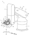
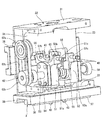
As shown in FIGS. 1 to 3, the
多関節ロボット2は、図1に示すように、基台6と、この基台6に支持された第1〜第5のアーム7〜11などによって構成されている。基台6の上には、第1のアーム7が第1の軸線C1を回動中心として回動可能に設けられている。第1のアーム7には、第2のアーム8が第2の軸線C2を揺動中心として揺動可能に設けられている。第2のアーム8には、第3のアーム9が第3の軸線C3を揺動中心として揺動可能に設けられている。
As shown in FIG. 1, the articulated
第3のアーム9には、第4のアーム10が第4の軸線C4を回動中心として回動可能に設けられている。第4のアーム10には、第5のアーム11が第5の軸線C5を揺動中心として揺動可能に設けられている。第5のアーム11には、ツール取付座12が第6の軸線C6を回動中心として回動可能に設けられている。ツール取付座12は、この実施の形態による、電動グリッパ装置1やその他のツール(図示せず)を取付けるためのものである。
The
電動グリッパ装置1の第1〜第3のハンド3〜5は、それぞれワークWを挟むための第1の爪3a,4a,5aおよび第2の爪3b,4b,5bを有している。全ての第1の爪3a,4a,5aは、詳細は後述するが、同一方向に移動する。全ての第2の爪3b,4b,5bは、第1の爪3a,4a,5aと協働してワークWを挟んで把持したりワークWを解放するために、第1の爪3a,4a,5aとは逆方向に移動する。第1の爪3a,4a,5aと第2の爪3b,4b,5bとの間にワークWが位置している状態で第1の爪3a,4a,5aと第2の爪3b,4b,5bとが互いに接近することにより、これらの第1および第2の爪によってワークWが挟まれて把持される。以下においては、第1および第2の爪がワークWを挟むときに移動する方向を単にワーク把持・解放方向という。
The first to
このワーク把持・解放方向は、第6の軸線C6とは直交する方向である。この実施の形態においては、便宜上、図1に示すように、第6の軸線C6と平行な方向を単に上下方向といい、この上下方向とワーク把持・解放方向の両方と直交する方向を単に左右方向という。また、以下においては、電動グリッパ装置1における第5のアーム11に近接する位置を上として説明する。
This workpiece gripping / releasing direction is a direction orthogonal to the sixth axis C6. In this embodiment, for convenience, as shown in FIG. 1, the direction parallel to the sixth axis C6 is simply referred to as the vertical direction, and the direction perpendicular to both the vertical direction and the workpiece gripping / releasing direction is simply left and right. It is called direction. Moreover, below, the position which adjoins the
この実施の形態による電動グリッパ装置1は、上述したツール取付座12に取付けられる筐体21に、第1〜第3のハンド3〜5と、これらのハンド3〜5を駆動する駆動装置22(図4および図5参照)などを組付けて構成されている。
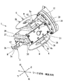
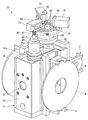
筐体21は、図1〜図3に示すように、直方体状に形成されている。この実施の形態による筐体21は、図7に示すように、複数の部品を組み合わせて中空の直方体状に形成されている。複数の部品とは、断面コ字状に形成された第1の側板23と、この第1の側板23と協働して角筒を構成する第2の側板24と、この角筒の一方の開口部分を閉塞する第1の蓋体25と、この角筒の他方の開口部に隔壁26を介して取付けられた第2の蓋体27などである。
The
The housing | casing 21 is formed in the rectangular parallelepiped shape, as shown in FIGS. As shown in FIG. 7, the
隔壁26と第2の蓋体27は、上述した角筒の他方の開口部を閉塞している。なお、以下においては、断面コ字状を呈する第1の側板23の開放部分が指向する方向(図7においては右斜め下を指向する方向)を右方向として説明する。
この筐体21を構成する直方体は、上述したワーク把持・開放方向に延びる四つの側面を有している。これらの側面とは、図5に示すように、上面21aと、底面21bと、左側面21cと、右側面21dである。
The
The rectangular parallelepiped constituting the
四つの側面のうち、図5において最も上に位置する上面21aを有する上壁31には、図6および図7に示すように、上述したツール取付座12に取付けられる取付部32が設けられている。この実施の形態においては、上壁31が請求項4記載の発明でいう「筐体の一側部」に相当する。
第1〜第3のハンド3〜5は、図5に示すように、上述した四つの側面のうち、上面21aを除く他の三つの側面と対応する、底壁33、左側壁34および右側壁35に設けられている。この実施の形態においては、これらの底壁33、左側壁34および右側壁35が請求項4記載の発明でいう「三つの側部」に相当する。
Of the four side surfaces, the
As shown in FIG. 5, the first to
第1のハンド3は、底壁33に設けられている。第2のハンド4は、左側壁34に設けられている。第3のハンド5は、右側壁35に設けられている。第1〜第3のハンド3〜5は、同等の構成が採られている。このため、ここでは第1のハンド3について詳細に説明する。第2および第3のハンド4,5については、第1のハンド3と異なる構成のみについて説明し、その他の構成は、第1のハンド3と同一符号を付して詳細な説明は省略する。
The
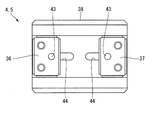
第1のハンド3は、図4および図5に示すように、筐体21の底壁33に沿う第1のスライダ36と第2のスライダ37とを有している。これらの第1および第2のスライダ36,37は、底壁33にワーク把持・解放方向へ延びる状態で固定された1本のレール38に往復移動自在に支持されている。第1および第2のスライダ36,37は、後述する駆動装置22により駆動されることによって、レール38に沿って移動し、互いに接近したり離間する。このため、第1および第2のスライダ36,37は、筐体21の外面にワーク把持・解放方向へ往復移動自在に支持されることになる。
As shown in FIGS. 4 and 5, the
第1および第2のスライダ36,37とレール38は、いわゆるリニアガイドを構成するものである。レール38は、筐体21におけるワーク把持・解放方向の一端から他端まで延びる形状に形成されており、第1および第2のスライダ36,37が挿入される溝39を有している。この溝39の互いに対向する内側壁39a,39bと第1および第2のスライダ36,37との間には、それぞれボール40が介在されている。このボール40は、第1および第2のスライダ36,37に保持された状態でレール38のボール溝41に回転可能に挿入されている。なお、第1および第2のスライダ36,37は、ボール40が第1および第2のスライダ36,37内の循環路(図示せず)を通って循環する、いわゆる循環ボール式のものを用いることができる。
The first and
第1のスライダ36には、図2および図3に示すように、第1の爪3aが取付けられている。第2のスライダ37には、第2の爪3bが取付けられている。この実施の形態による爪3a,3bは、円板状のワークWを挟んで把持するものであり、左右方向の一方(図2においては下方)に向けて開放される凹部42を有している。ワークWは、この凹部42内に外周部の一部が挿入された状態で第1および第2の爪3a,3bによって挟まれて把持される。すなわち、第1のハンド3は、第1の爪3aが取付けられた第1のスライダ36と、第2の爪3bが取付けられた第2のスライダ37とによって構成されている。なお、図2および図3は、構成を理解し易いように、第1〜第3のハンド3〜5がそれぞれワークWを把持した状態で描いてある。しかし、この電動グリッパ装置1は、第1〜第3のハンド3〜5のうち一つのハンドのみを使用してワークWを把持するものである。
As shown in FIGS. 2 and 3, a
第1のハンド3の第1および第2の爪3a,3bは、比較的小さいワークWを把持するものであり、第1のスライダ36と第2のスライダ37の互いに近接する端部の近傍に位置付けられている。
第2および第3のハンド4,5の第1の爪4a,5aと第2の爪4b,5bは、比較的大きいワークWを把持するものであり、第1のスライダ36と第2のスライダ37の互いに離間する端部の近傍に位置付けられている。なお、第1の爪と第2の爪との間隔(第1のスライダ36が第2のスライダ37に最も接近したときの間隔)は、ハンド毎に異なる間隔に設定することができる。また、図示してはいないが、ハンド毎に第1の爪と第2の爪の形状を変えることができる。この構成を採ることにより、形状の異なるワーク(四角、丸等)も把持することが可能になる。
The first and
The
第1および第2のスライダ36,37には、図4および図5に示すように、後述する駆動装置22から動力を伝えるために、それぞれピン43が設けられている。ピン43は、第1および第2のスライダ36,37に固定されており、第1および第2のスライダ36,37からレール38の貫通穴44と底壁33の貫通穴45とに通されて筐体21の内部に延びている。貫通穴44,45は、ピン43のワーク把持・解放方向への移動を許容するために、ワーク把持・解放方向に長く形成されている。
As shown in FIGS. 4 and 5, the first and
第1のスライダ36に設けられたピン43の先端部は、筐体21内に設けられた第1の移動部材51に固定されている。第2のスライダ37に設けられたピン43の先端部は、筐体21内に設けられた第2の移動部材52に固定されている。このため、第1のスライダ36は、ピン43を介して第1の移動部材51に連結され、第2のスライダ37は、ピン43を介して第2の移動部材52に連結されている。
The tip of the
第1の移動部材51と第2の移動部材52は、図5および図6に示すように、それぞれ上下方向に延びる本体部51a,52aと、この本体部51a,52aの上端部から左側に延びる左側アーム部51b,52bと、本体部51a,52aの上端部から右側に延びる右側アーム部51c,52cとを有している。上述した第1のハンド3の第1および第2のスライダ36,37と第1および第2の移動部材51,52とを連結するピン43は、本体部51a,52aの下端部であって左右方向の中央部に接続されている。
As shown in FIG. 5 and FIG. 6, the first moving
本体部51a,52aの上下方向の中央部には、後述するボールねじ軸53と、このボールねじ軸53に螺合する第1および第2のボールねじナット54,55とが貫通している。第1のボールねじナット54は、第1の移動部材51を貫通している。第2のボールねじナット55は、第2の移動部材52を貫通している。第1の移動部材51と第2の移動部材52は、ボールねじ軸53に第1および第2のボールねじナット54,55を介して支持されている。
A ball screw shaft 53 (to be described later) and first and second
第1および第2の移動部材51,52の左側アーム部51b,52bの先端部は、筐体21の左側壁34に形成された貫通穴56の中に収容される形状に形成されている。この先端部には、第2のハンド4のピン43が接続されている。このピン43は、左側アーム部51bの先端部に、ここを左右方向に貫通する状態で固定されている。
第1および第2の移動部材51,52の右側アーム部51c,52cの先端部は、筐体21の右側壁35に形成された貫通穴57の中に収容される形状に形成されている。この先端部には、第3のハンド5のピン43が接続されている。このピン43は、右側アーム部51c,52cの先端部に、ここを左右方向に貫通する状態で固定されている。
The distal end portions of the
The distal end portions of the
このため、全ての第1のスライダ36が第1の移動部材51に連結されるとともに、全ての第2のスライダ37が第2の移動部材52に連結されることになる。
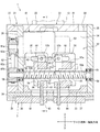
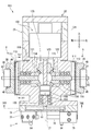
第1の移動部材51と第2の移動部材52とを支持するボールねじ軸53は、図4に示すように、ワーク把持・解放方向(図4においては左右方向)に延びる状態で筐体21内の下部に配置されており、筐体21の第1の蓋体25と隔壁26とにそれぞれ軸受58,59によって回転自在に支持されている。軸受58は、蓋体25と軸受58との間に設けられた波ワッシャ65によって隔壁26に向けて付勢されている。この波ワッシャ65の押圧力が軸受58に加えられることにより、この押圧力が軸受58からボールねじ軸53を介して軸受59に伝達され、軸受59が隔壁26に押し付けられる。このため、ボールねじ軸53と軸受58,59は、ワーク把持・解放方向においてガタが無い状態で筐体21に支持されている。この実施の形態においては、このボールねじ軸53が本発明でいう「駆動軸」に相当する。
Therefore, all the
As shown in FIG. 4, the
上述した第1のハンド3の第1および第2のスライダ36,37は、図5に示すように、ボールねじ軸53の下方近傍に配置されている。第2のハンド4の第1および第2のスライダ36,37は、ボールねじ軸53の左方近傍に配置されている。第3のハンド5の第1および第2のスライダ36,37は、ボールねじ軸53の右方近傍に配置されている。すなわち、この実施の形態による第1〜第3のハンド3〜5の第1および第2のスライダ36,37は、図5に示すように、ワーク把持・解放方向から見てボールねじ軸53と隣り合う複数の位置にそれぞれ設けられている。
The first and
ボールねじ軸53の軸線方向の一端側には第1のねじ部53aが形成され、他端側には第2のねじ部53bが形成されている。これらの第1のねじ部53aと第2のねじ部53bとは、ねじの方向が互いに逆になるように形成されている。
第1のねじ部53aには、第1のボールねじナット54が螺合する状態で支持されている。この第1のボールねじナット54の回転は、第1の移動部材51と、3本のピン43と、第1のスライダ36およびレール38などの部材を介して接続された筐体21によって規制される。
A
A first
第2のねじ部53bには、第2のボールねじナット55が螺合する状態で支持されている。この第2のボールねじナット55の回転は、第2の移動部材52と、3本のピン43と、第2のスライダ37およびレール38などの部材を介して接続された筐体21によって規制される。
このため、第1の移動部材51と第2の移動部材52は、ボールねじ軸53が例えば正転することにより互いに接近する方向に移動し、ボールねじ軸53が逆転することにより互いに離間する方向に移動する。
A second
For this reason, the first moving
駆動装置22は、このように第1の移動部材51と第2の移動部材52とを1本のボールねじ軸53で互いに逆方向へ駆動するものである。この実施の形態による駆動装置22は、上述したボールねじ軸53と、第1および第2のボールねじナット54,55と、筐体21内の上部に配置されたモータ61と、このモータ61とボールねじ軸53とを接続するボールねじ軸用伝動機構62とを備えている。
In this way, the driving
モータ61は、エンコーダ63を有するサーボモータで、筐体21におけるロボット2のツール取付座12に取付けられる取付部32(上壁31)と、ボールねじ軸53との間に配置されている。また、このモータ61は、図4に示すように、軸線がワーク把持・解放方向を指向し、回転軸61aが隔壁26から筐体21の外に向けて突出する状態で隔壁26に固定されている。このモータ61は、図示してはいないが、ケーブルを介して制御装置に接続されている。ケーブルは、筐体21内から上壁31の貫通孔64と、ロボット2の第1〜第5のアーム部7〜11の中とを通されて基台6の中に延びている。モータ61の動作は、制御装置によって制御される。
The
伝動機構62は、モータ61の回転軸61aに取付けられた駆動側プーリ62aと、ボールねじ軸53の軸端部に取付けられた従動側プーリ62bと、これらの両プーリ62a,62bの間に架け渡されたベルト62cとによって構成されている。この伝動機構62は、モータ61の回転を駆動側プーリ62aと、ベルト62cと、従動側プーリ62bとを介してボールねじ軸53に伝達する。このため、モータ61の回転に伴ってボールねじ軸53が回転し、第1および第2の移動部材51,52が駆動される。この実施の形態においては、この伝動機構62が請求項3記載の発明でいう「ボールねじ軸用伝動機構」に相当する。
The
第1および第2の移動部材51,52が互いに接近する方向に移動することにより、これらの移動部材51,52にピン43を介して連結された第1〜第3のハンド3〜5の第1および第2のスライダ36,37が互いに接近し、これに伴って第1〜第3のハンド3〜5の第1の爪3a,4a,5aと第2の爪3b,4b,5bとの間隔が狭くなる。一方、第1および第2の移動部材51,52が互いに離間する方向に移動することにより、第1〜第3のハンド3〜5の第1および第2のスライダ36,37が互いに離間し、これに伴って第1〜第3のハンド3〜5の第1の爪3a,4a,5aと第2の爪3b,4b,5bとの間隔が拡がる。この実施の形態においては、第1および第2のボールねじナット54,55と、第1、第2の移動部材51,52と、各スライダのピン43などの部材によって、本発明でいう「回転軸の回転をワーク把持・解放方向への平行移動に変換して第1のスライダと第2のスライダとに伝達するスライダ用伝動機構」が構成されている。また、第1、第2の移動部材51,52および各スライダのピン43は、ボールねじ軸53から第1〜第3のハンド3〜5の全ての第1および第2のスライダ36,37にそれぞれ動力を伝達する「伝動部材」を構成している。
When the first and second moving
このように構成された電動グリッパ装置1においては、筐体21の複数の位置、すなわち3箇所にハンド(第1〜第3のハンド3〜5)が設けられている。このため、筐体21の位置をロボット2の軸線C5や軸線C6等を回転させて変えることによって、第1〜第3のハンド3〜5のうち、ワークWに適合するハンドを選択することができる。これらの第1〜第3のハンド3〜5の第1および第2の爪は、ボールねじ軸53が回転することにより、ワーク把持・解放方向に移動する。このため、一つの駆動装置22で複数のハンドを駆動することが可能になる。この電動グリッパ装置1は、ハンド毎にアクチュエータを備えている従来の装置と較べると、駆動装置22およびケーブルが1台分でよいから、軽量で、しかも、それらの設置スペースが狭くてよいから、コンパクトなものとなる。また、駆動装置22およびケーブルの設置作業も簡単に行うことができるし、駆動装置22の制御も簡単に行うことができる。
In the
したがって、この実施の形態によれば、複数のハンドを装備しているにもかかわらず、軽量かつコンパクトで、しかも制御用ケーブルの設置や制御を簡単に行うことが可能な電動グリッパ装置を提供することができる。この電動グリッパ装置が装備されたロボットハンドの先端部は、小型、軽量となる。 Therefore, according to this embodiment, it is possible to provide an electric gripper device that is light and compact, and can easily install and control a control cable, despite being equipped with a plurality of hands. be able to. The tip of the robot hand equipped with this electric gripper device is small and light.
この実施の形態による駆動装置22は、ボールねじ軸53に伝動機構62を介して接続されたモータ61を備えている。このモータ61は、筐体21におけるツール取付座12に取付けられる取付部32と、ボールねじ軸53との間に配置されている。
このため、モータ61が第1および第2の移動部材51,52の動作を遮ることがない位置に配置されるから、コンパクトな電動グリッパ装置を提供することができる。
The
For this reason, since the
特にこの実施の形態によれば、図5に示すように、左側アーム部51a,52a先端部が筐体21の左側壁34の貫通孔56に収容され、右側アーム部51c,52cの先端部が筐体21の右側壁35の貫通孔56に収容されている。このため、左側アーム部51b,52bおよび右側アーム部51c,52cとモータ61との干渉を避けながらモータ61を低い位置に配置することができるから、筐体21を上下方向により一層コンパクトに形成することができる。
In particular, according to this embodiment, as shown in FIG. 5, the
この実施の形態による筐体21は、ワーク把持・解放方向に延びる四つの側面を有する直方体状に形成されている。この筐体21におけるツール取付座12に取付けられる取付部32は、四つの側面のうちの一つの側面を有する筐体21の上壁31に設けられている。第1および第2のスライダ36,37は、筐体21の四つの側面のうちの他の三つの側面と対応する底壁33、左側壁34および右側壁35にそれぞれ設けられている。すなわち、これらのハンドは、筐体21の3箇所に設けられている。
このため、この実施の形態によれば、三つのハンドを有する電動グリッパ装置を簡単に実現することができる。
The
For this reason, according to this embodiment, an electric gripper device having three hands can be easily realized.
(第2の実施の形態)
本発明に係る電動グリッパ装置は、図8〜図10に示すように構成することができる。これらの図において、図1〜図7によって説明したものと同一もしくは同等の部材については、同一符号を付し詳細な説明を適宜省略する。
図8に示す電動グリッパ装置71は、第1の実施の形態で示した電動グリッパ装置1の筐体21に第4のハンド72を追加したものである。
(Second Embodiment)
The electric gripper device according to the present invention can be configured as shown in FIGS. In these drawings, members that are the same as or equivalent to those described with reference to FIGS. 1 to 7 are given the same reference numerals, and detailed descriptions thereof are omitted as appropriate.
An
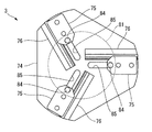
第4のハンド72は、筐体21の第2の蓋体27に板状の支持部材73を介して取付けられたレール台74と、このレール台74に設けられた三つのフィンガブロック75とを備えている。これらのフィンガブロック75は、ワークW(図示せず)を第1の実施の形態でいう「ワーク把持・解放方向」とは直交する3方向から挟んで把持するもので、レール台74に設けられた3本のレール76に移動自在に支持されている。
The
三つのフィンガブロック75は、上述したワーク把持・解放方向から見て、フィンガブロック75どうしの相対角度が120度となるように配置されている。この実施の形態においては、これらのフィンガブロック75が請求項5記載の発明でいう「爪部材」に相当する。
The three
レール台74の内部には、図9に示すように、円板状のカム部材81が設けられている。このカム部材81は、支持部材73に軸受82を介して回転自在に支持されている。すなわち、カム部材81は、筐体21におけるワーク把持・解放方向の一端側に位置する側部に、ワーク把持・解放方向を軸線方向として回転自在に支持されている。
上述した三つのフィンガブロック75は、ワーク把持・解放方向から見て、支持部材73の軸線を中心として放射状に並んでおり、この軸線に対して接離する方向に移動自在である。
As shown in FIG. 9, a disc-shaped
The three finger blocks 75 described above are arranged in a radial pattern around the axis of the
また、このカム部材81には、図10に示すように、三つの渦巻き状のカム溝83が同芯状に形成されている。これらのカム溝83は、いわゆるアルキメデスのうず巻線に沿う形状に形成されている。これらのカム溝83には、ピン状のカムフォロア84の一端部が移動自在に嵌合している。これらのカムフォロア84の他端側は、レール台74のガイド孔85(図8参照)を貫通し、フィンガブロック75に固定されている。ガイド孔85は、カムフォロア84が嵌合する開口幅でレール76と平行に延びる形状に形成されている。
Further, the
この実施の形態によるカム部材81は、外周部に歯86を有する歯車を構成している。この歯86には、図9に示すように、ピニオン87が噛合している。このピニオン87は、モータ61の回転軸61aと同一軸線上に位置する状態で支持部材73に軸受88によって回転自在に支持されている。また、このピニオン87は、モータ61の回転軸61aにカップリング89を介して連結されている。この実施の形態において、駆動装置22(図示せず)の動力は、モータ61の回転軸61aからカップリング89と、ピニオン87と、カム部材81の外周部に設けられた歯86とからなるカム部材用伝動機構90を介してカム部材81に伝達される。
The
この実施の形態による第4のハンド72は、モータ61と一体にピニオン87が回転することにより、カム部材81が回転し、カム溝83によって回転運動が直線運動に変換されてカムフォロア84とフィンガブロック75とがカム部材81の径方向に移動する。この結果、三つのフィンガブロック75どうしの間隔が変わり、これらのフィンガブロック75によってワークWを把持、あるいは解放することが可能になる。
In the
また、この実施の形態によれば、三つのフィンガブロック75を有する第4のハンド72が上述した第1〜第3のハンド3〜5の他に筐体21に設けられる。この四つ目の第4のハンド72は、第1〜第3のハンド3〜5と共通の駆動装置22によって駆動される。
したがって、この実施の形態によれば一つの駆動装置22で四つのハンドを駆動できる電動グリッパ装置を提供できる。
Moreover, according to this embodiment, the
Therefore, according to this embodiment, it is possible to provide an electric gripper device that can drive four hands with one
この実施の形態によれば、モータ61の回転角と、三つのフィンガブロック75の移動量(ハンドの開閉ストローク)が線形な関係となっているため、第1〜第3のハンド3〜5と第4のハンド72とを同一の制御方法で制御することが可能である。
なお、この実施の形態においては、3個のフィンガブロック75を使用する例を示した。しかし、本発明は、このような限定にとらわれることはない。すなわち、カム部材81に設けられているカム溝83の条数を変えることにより、フィンガブロック75の個数を2個あるいは4個などに変えることができる。
According to this embodiment, since the rotation angle of the
In this embodiment, an example in which three
(第3の実施の形態)
本発明に係る電動グリッパ装置は、図11〜図15に示すように構成することができる。これらの図において、図1〜図10によって説明したものと同一もしくは同等の部材については、同一符号を付し詳細な説明を適宜省略する。
この実施の形態による電動グリッパ装置101は、図1〜図10によって説明した電動グリッパ装置1,71とは駆動装置102の構成が異なるだけで、その他の構成は同等のものである。
(Third embodiment)
The electric gripper device according to the present invention can be configured as shown in FIGS. In these drawings, the same or equivalent members as those described with reference to FIGS. 1 to 10 are denoted by the same reference numerals, and detailed description thereof is omitted as appropriate.
The
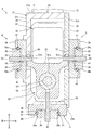
この実施の形態による電動グリッパ装置101の筐体21は、図11の上下方向に長い中空の立方体状に形成されている。なお、図11に示す筐体21は、構造を理解し易いように、部品数を減らした状態で描いてあり、実際の筐体21は、複数の部材をボルトで組み合わせて構成されている。この筐体21の長手方向の一端部(図11においては上側の端部)には、多関節ロボット2のツール取付座12に取付けられる取付部32が設けられている。以下においては、便宜上、図11の上下方向を電動グリッパ装置101の上下方向とし、図11の左右方向を電動グリッパ装置101の左右方向として説明する。
The
筐体21における取付部32を有する上面と対向する下面には第1のハンド3が設けられている。また、筐体21における上下方向に延びる四つの側面のうち、互いに対向する左側面と右側面には、第2および第3のハンド4,5が設けられている。なお、図11は、ワークを把持する爪を省略して描いてある。これらの第1〜第3のハンド3〜5のうち、第1のハンド3は、第2および第3のハンド4,5とは構成が異なっている。
The
この実施の形態による第1のハンド3は、図8に示した第4のハンド72と同等の構造で、図12に示すように、3個のフィンガブロック75を有している。これらのフィンガブロック75は、レール76に移動自在に支持されており、ピン84を介して円板状のカム部材81に接続されている。この実施の形態においては、これらのフィンガブロック75が請求項7記載の発明でいう「複数の爪部材」に相当する。レール76は、筐体21に取付けられたレール台74に固定されている。このため、これらのフィンガブロック75は、筐体21にレール76とレール台74とを介して後述するカム部材81の軸線C7(図11参照)に対して接離する方向へ移動自在に支持されている。
The
この実施の形態によるカム部材81は、図10に示したものとは駆動系の構成が異なっている。このカム部材81の駆動は、軸心部に設けられた第1の従動軸103を介して行われる。第1の従動軸103は、カム部材81の軸心部にカム部材81と同一軸線上に位置する状態に固定されている。この第1の従動軸103は、軸受104によって筐体21に回転自在に支持されている。
The
第1の従動軸103の軸線方向は、図11の上下方向と平行な方向であって、取付部32の面とは直交する方向である。この第1の従動軸103の先端部(図11においては上端部)は、カップリング105を介して後述する駆動装置102の駆動軸106に連結されている。すなわち、カム部材81は、駆動軸106の先端部に一体に回転する状態に設けられている。カム部材81には、図13に示すように、渦巻き状の三つのカム溝83が同芯状に形成されている。各フィンガブロック75のピン84は、このカム溝83に移動自在に嵌合している。このため、カム部材81が回動することにより、三つのフィンガーブロック75が同時にカム部材81の軸線C7に対して接離する。
The axial direction of the first driven
第2および第3のハンド4,5は、互いに同一の構成が採られている。これらの第2および第3のハンド4,5は、筐体21にレール台111を介して取付けられたレール38と、このレール38に移動自在に支持された第1および第2のスライダ36,37(図14参照)などを有している。レール38と第1および第2のスライダ36,37との間にはボール40が介在している。第1および第2のスライダ36,37が移動する方向(ワーク把持・解放方向)は、図11の紙面と直交する方向である。言い換えれば、第1および第2のスライダ36,37は、上述した第1の従動軸103の軸線C7と直交する方向であって、かつ第2のハンド4と第3のハンド5とが並ぶ方向(図11において左右方向)と直交する方向である。
The second and
第1および第2のスライダ36,37は、筐体21内に向けて延びるピン43をそれぞれ備えている。このピン43は、レール38の貫通穴44に挿入されてレール台111の中に延びており、レール台111の内部に収容された円板状のカム部材112に接続されている。この実施の形態においては、第1のスライダ36のピン43が請求項6記載の発明でいう「第1のカムフォロア」を構成し、第2のスライダ37のピン43が請求項6記載の発明でいう「第2のカムフォロア」を構成している。
The first and
カム部材112には、図15に示すように、渦巻き状の二つのカム溝113が同芯状に形成されている。第1のスライダ36のピン43と、第2のスライダ37のピン43は、それぞれカム溝113に移動自在に嵌合している。これらのカム溝113は、図10および図13に示したカム溝83と同様に、いわゆるアルキメデスのうず巻線に沿う形状に形成されている。このため、カム部材112が正転あるいは逆転することにより、第1および第2のスライダ36,37が同時にワーク把持方向あるいはワーク解放方向に移動する。
As shown in FIG. 15, the
第2のハンド4のカム部材112の軸心部には、第2の従動軸114が同一軸線上に位置する状態に設けられている。第3のハンド5のカム部材112の軸心部には、第3の従動軸115が同一軸線上に位置する状態に設けられている。これらの第2および第3の従動軸114,115は、それぞれカム部材112から筐体21の内部に向けて延びており、筐体21に軸受116によって回転自在に支持されている。
A second driven
第2の従動軸114の先端部には第2のハンド用の従動側傘歯車121が取付けられている。第3の従動軸115の先端部には第3のハンド用の従動側傘歯車122が取付けられている。すなわち、これらの第2および第3の従動軸114,115は、従動側傘歯車121,122が一端部に取付けられるとともに他端部にカム部112を有し、このカム部材112が第2のハンド4あるいは第3のハンド5の近傍に位置するように筐体21に回転自在に支持されている。従動側傘歯車121,122は、後述する駆動装置102の駆動側傘歯車123に噛合している。
A driven
この実施の形態による駆動装置102は、筐体21における第1のハンド3とは反対側の端部に設けられたモータ124を動力源として第1〜第3のハンド3〜5を同時に駆動する。モータ124は、筐体21の長手方向を軸線方向として筐体21に支持されている。第1のハンド3の第1の従動軸103に接続された駆動軸106は、このモータ124の回転軸によって構成されている。すなわち、駆動軸106は、筐体21に回転自在に支持されることになる。駆動軸106は、筐体21の中央部であって、第2のハンド4と第3のハンド5の間に配置されている。このため、第2のハンド4と第3のハンド5は、駆動軸106の軸線方向から見て駆動軸106と隣り合う複数の位置に設けられている。
The
この実施の形態による駆動装置102は、上述したモータ124および駆動軸106と、この駆動軸106の中間部に固定された駆動側傘歯車123を含むスライダ用伝動機構125などを備えている。スライダ用伝動機構125は、後述する伝動部材によって駆動軸106から全ての第1および第2のスライダ36,37にそれぞれ動力を伝達する機能を有している。この伝動部材とは、駆動側傘歯車123と、この駆動側傘歯車123に噛合した二つの従動側傘歯車121,122と、これらの従動側傘歯車121,122と一体に回転する第2および第3の従動軸114,115と、これらの第2および第3の従動軸114,115にそれぞれ設けられた二つのカム部材112,112と、これらのカム部材112に接続された第1および第2のスライダ36,37毎のピン43,43などである。このため、スライダ用伝動機構125は、駆動軸106の回転をワーク把持・解放方向への平行移動に変換して第1のスライダと第2のスライダとに伝達する。
The
したがって、この実施の形態においても、一つの駆動装置102で複数のハンド(第2および第3のハンド4,5)を駆動することが可能になるから、第1および第2の実施の形態を採るときと同等の効果が得られる。
また、駆動軸106の回転は、第1の従動軸103とカム部材81とピン84とによってワーク把持・解放方向への平行移動に変換されて第1のハンド3の三つのフィンガブロック75に伝達される。このため、この実施の形態によれば、3個のハンド(第1〜第3のハンド3〜5)が同時に駆動される電動グリッパ装置101を第1の実施の形態を採る場合と較べて安価に提供することができる。安価である理由は、1本の駆動軸106の回転を往復運動に変換して第1〜第3のハンド3〜5に伝達するにあたって、単純な部品である軸(第1〜第3の従動軸103,114,115)、傘歯車(駆動側傘歯車123、従動側傘歯車121,122)、カム部材(カム部材81,112)およびピン(ピン84,43)などが用いられており、これらの部材はボールねじ機構と較べると低価格だからである。
Accordingly, also in this embodiment, a plurality of hands (second and
The rotation of the
第3の実施の形態においては、筐体21における取付部32を有する側面とは直交する四つの側面のうち、左側面に第2のハンド4を設け、右側面に第3のハンド5を設ける例を示した。しかし、本発明は、このような限定にとらわれることはなく、四つの側面のうち残りの二つの側面にもそれぞれハンドを設けることができる。
In the third embodiment, among the four side surfaces orthogonal to the side surface having the
1,71,101…電動グリッパ装置101、2…多関節ロボット、3…第1のハンド3、4…第2のハンド4、5…第3のハンド5、3a,4a,5a…第1の爪、3b,4b,5b…第2の爪、12…ツール取付座、21…筐体21、21a,21b,21c,21d…側面、22…駆動装置102、27…第2の蓋体(側部)、31…上壁(一側部)、32…取付部、33…底壁(側部)、34…左側壁(側部)、35…右側壁(側部)、36…第1のスライダ、37…第2のスライダ、43,84…ピン、51…第1の移動部材、52…第2の移動部材、53…ボールねじ軸、61,124…モータ、62…伝動機構(ボールねじ軸用伝動機構)、72…第4のハンド、75…フィンガブロック75(爪部材)、81,112…カム部材、83,113…カム溝、84…カムフォロア、90…カム部材用伝動機構、103…第1の従動軸、106…駆動軸、114…第2の従動軸、115…第3の従動軸、121,122…従動側傘歯車、123…駆動側傘歯車、125…スライダ用伝動機構、W…ワーク。
DESCRIPTION OF
Claims (7)
ワークを挟んで把持するための第1の爪を有し、前記筐体の外面にワーク把持・解放方向へ往復移動自在に支持された第1のスライダと、
前記第1の爪と協働してワークを挟む第2の爪を有し、前記筐体の外面であって前記第1のスライダとは隣り合う位置に前記ワーク把持・解放方向へ往復移動自在に支持されて前記第1のスライダと協働してハンドを構成する第2のスライダと、
前記第1および第2のスライダを互いに逆方向へ駆動する駆動装置とを備え、
前記駆動装置は、
前記筐体に回転自在に支持された駆動軸と、
前記駆動軸を駆動するモータと、
前記駆動軸の回転を前記ワーク把持・解放方向への平行移動に変換して前記第1のスライダと前記第2のスライダとに伝達するスライダ用伝動機構とを有し、
前記ハンドは、前記駆動軸の軸線方向から見て前記駆動軸と隣り合う複数の位置にそれぞれ設けられ、
前記伝動機構は、前記駆動軸から前記各ハンドの全ての第1および第2のスライダにそれぞれ動力を伝達する伝動部材を有している電動グリッパ装置。 A housing that can be attached to the tool mounting seat of the robot;
A first slider having a first claw for gripping the workpiece, supported on the outer surface of the housing so as to be reciprocally movable in the workpiece gripping / release direction;
A second claw that sandwiches the workpiece in cooperation with the first claw, and is capable of reciprocating in the workpiece gripping / releasing direction at a position adjacent to the first slider on the outer surface of the housing. A second slider which is supported by the first slider and forms a hand in cooperation with the first slider;
A driving device for driving the first and second sliders in opposite directions;
The driving device includes:
A drive shaft rotatably supported by the housing;
A motor for driving the drive shaft;
A slider transmission mechanism that converts the rotation of the drive shaft into a parallel movement in the workpiece gripping / releasing direction and transmits the translation to the first slider and the second slider;
The hand is provided at each of a plurality of positions adjacent to the drive shaft as viewed from the axial direction of the drive shaft,
The power transmission mechanism is an electric gripper device having a power transmission member that transmits power from the drive shaft to all the first and second sliders of each hand.
前記駆動軸は、ボールねじ軸によって構成され、
前記ボールねじ軸は、ねじの方向が互いに逆になる第1のねじ部と第2のねじ部とを有し、
前記伝動機構は、
前記第1のねじ部に螺合した第1のボールねじナットと、
前記第2のねじ部に螺合した第2のボールねじナットと、
前記第1のボールねじナットと全ての第1のスライダとを接続する前記伝動部材としての第1の移動部材と、
前記第2のボールねじナットと全ての第2のスライダとを接続する前記伝動部材としての第2の移動部材とを有していることを特徴とする電動グリッパ装置。 The electric gripper device according to claim 1, wherein
The drive shaft is constituted by a ball screw shaft,
The ball screw shaft has a first screw portion and a second screw portion in which screw directions are opposite to each other,
The transmission mechanism is
A first ball screw nut threadably engaged with the first thread portion;
A second ball screw nut threadably engaged with the second thread portion;
A first moving member as the transmission member for connecting the first ball screw nut and all the first sliders;
An electric gripper device comprising: a second moving member as the transmission member that connects the second ball screw nut and all the second sliders.
前記駆動装置は、前記モータと前記駆動軸とを接続するボールねじ軸用伝動機構を有し、
前記モータは、前記筐体における前記ツール取付座に取付けられる取付部と、前記ボールねじ軸との間に配置されていることを特徴とする電動グリッパ装置。 The electric gripper device according to claim 2,
The drive device has a transmission mechanism for a ball screw shaft that connects the motor and the drive shaft,
The electric gripper device, wherein the motor is disposed between an attachment portion attached to the tool attachment seat in the housing and the ball screw shaft.
前記筐体は、前記ワーク把持・解放方向に延びる四つの側面を有する直方体状に形成され、
前記筐体における前記ツール取付座に取付けられる取付部は、前記四つの側面のうちの一つの側面を有する前記筐体の一側部に設けられ、
前記第1および第2のスライダは、前記四つの側面のうちの他の三つの側面と対応する三つの側部にそれぞれ設けられていることを特徴とする電動グリッパ装置。 In the electric gripper device according to any one of claims 1 to 3,
The housing is formed in a rectangular parallelepiped shape having four side surfaces extending in the workpiece gripping / releasing direction,
The mounting portion attached to the tool mounting seat in the housing is provided on one side of the housing having one of the four side surfaces,
The electric gripper device, wherein the first and second sliders are respectively provided on three side portions corresponding to the other three side surfaces of the four side surfaces.
渦巻き状の複数のカム溝が同芯状に形成され、前記筐体における前記ワーク把持・解放方向の一端側に位置する側部に、ワーク把持・解放方向を軸線方向として回転自在に支持されたカム部材と、
前記カム溝に移動自在に挿入されたカムフォロアを有し、前記筐体に前記カム部材の軸線に対して接離する方向へ移動自在に支持された複数の爪部材と、
前記駆動装置から動力を前記カム部材に伝達するカム部材用伝動機構とを備えたことを特徴とする電動グリッパ装置。 The electric gripper device according to claim 4,
A plurality of spiral cam grooves are formed concentrically, and are supported rotatably on the side portion of the housing located on one end side in the workpiece gripping / release direction with the workpiece gripping / release direction as an axial direction. A cam member;
A plurality of claw members having a cam follower movably inserted in the cam groove and supported by the housing so as to be movable toward and away from the axis of the cam member;
An electric gripper device comprising: a cam member transmission mechanism for transmitting power from the drive device to the cam member.
前記駆動軸は、駆動側傘歯車を有し、
前記伝動機構は、
前記駆動側傘歯車に噛合する複数の従動側傘歯車と、
渦巻き状の複数のカム溝が同芯状に形成され、前記従動側傘歯車毎に設けられた複数のカム部材と、
前記従動側傘歯車が一端部に設けられるとともに他端部に前記カム部材が設けられ、このカム部材が前記各ハンドの近傍に位置するように前記筐体に回転自在に支持された複数の従動軸と、
前記第1のスライダに設けられ、前記カム溝に移動自在に挿入された第1のカムフォロアと、
前記第2のスライダに設けられ、前記カム溝に移動自在に挿入された第2のカムフォロアとを有していることを特徴とする電動グリッパ装置。 The electric gripper device according to claim 1, wherein
The drive shaft has a drive side bevel gear,
The transmission mechanism is
A plurality of driven bevel gears meshing with the drive bevel gear;
A plurality of spiral cam grooves are formed concentrically, and a plurality of cam members provided for each driven bevel gear;
The driven bevel gear is provided at one end and the cam member is provided at the other end, and a plurality of driven followers rotatably supported by the housing so that the cam member is positioned in the vicinity of each hand. The axis,
A first cam follower provided on the first slider and movably inserted in the cam groove;
An electric gripper device having a second cam follower provided on the second slider and movably inserted in the cam groove.
前記駆動軸の先端部に一体に回転する状態に設けられ、渦巻き状の複数のカム溝が同芯状に形成されたカム部材と、
前記カム溝に移動自在に挿入されたカムフォロアを有し、前記筐体に前記カム部材の軸線に対して接離する方向へ移動自在に支持された複数の爪部材とを備えたことを特徴とする電動グリッパ装置。 The electric gripper device according to claim 6,
A cam member provided in a state of rotating integrally with a tip end portion of the drive shaft, and a plurality of spiral cam grooves formed concentrically;
A plurality of claw members, each having a cam follower movably inserted in the cam groove, and supported by the housing in a direction to move toward and away from the axis of the cam member; Electric gripper device.
Priority Applications (1)
| Application Number | Priority Date | Filing Date | Title |
|---|---|---|---|
| JP2016087729A JP6666786B2 (en) | 2016-04-26 | 2016-04-26 | Electric gripper device |
Applications Claiming Priority (1)
| Application Number | Priority Date | Filing Date | Title |
|---|---|---|---|
| JP2016087729A JP6666786B2 (en) | 2016-04-26 | 2016-04-26 | Electric gripper device |
Publications (2)
| Publication Number | Publication Date |
|---|---|
| JP2017196679A true JP2017196679A (en) | 2017-11-02 |
| JP6666786B2 JP6666786B2 (en) | 2020-03-18 |
Family
ID=60238619
Family Applications (1)
| Application Number | Title | Priority Date | Filing Date |
|---|---|---|---|
| JP2016087729A Expired - Fee Related JP6666786B2 (en) | 2016-04-26 | 2016-04-26 | Electric gripper device |
Country Status (1)
| Country | Link |
|---|---|
| JP (1) | JP6666786B2 (en) |
Cited By (5)
| Publication number | Priority date | Publication date | Assignee | Title |
|---|---|---|---|---|
| CN109202703A (en) * | 2018-08-21 | 2019-01-15 | 东莞理工学院 | A kind of loading and unloading gripper |
| CN110224044A (en) * | 2018-03-01 | 2019-09-10 | 无锡市正罡自动化设备有限公司 | Busbar transmission apply printing equipment set, strap device and apply print scaling powder method |
| CN111906808A (en) * | 2020-08-28 | 2020-11-10 | 上海海事大学 | Multi-degree-of-freedom turbine shroud blade mechanical gripper device |
| CN112692551A (en) * | 2020-12-23 | 2021-04-23 | 西北工业大学 | Intelligent workpiece threading device and threading method based on visual positioning |
| CN113208736A (en) * | 2021-05-31 | 2021-08-06 | 上海微创医疗机器人(集团)股份有限公司 | Instrument driving device, instrument tail end assembly, surgical instrument and surgical robot |
Citations (9)
| Publication number | Priority date | Publication date | Assignee | Title |
|---|---|---|---|---|
| JPS55138038U (en) * | 1979-03-24 | 1980-10-01 | ||
| JPS6048980U (en) * | 1983-09-14 | 1985-04-06 | 三菱重工業株式会社 | handling robot |
| US4765668A (en) * | 1986-02-13 | 1988-08-23 | The United States Of America As Represented By The Secretary Of Commerce | Robot end effector |
| US5125709A (en) * | 1991-07-22 | 1992-06-30 | Ford Motor Company | Robotic gripper assembly |
| JP2002172580A (en) * | 2000-12-08 | 2002-06-18 | Koganei Corp | Electric actuator |
| JP2005059118A (en) * | 2003-08-08 | 2005-03-10 | Taiyo Ltd | Motor-driven hand |
| JP2012056052A (en) * | 2010-09-10 | 2012-03-22 | Yaskawa Electric Corp | Hand, and robot |
| JP2014094445A (en) * | 2012-10-11 | 2014-05-22 | Canon Inc | Holding device and robot device |
| JP2015003374A (en) * | 2013-06-24 | 2015-01-08 | 株式会社安川電機 | Robot, manufacturing method of robot, and bag body |
-
2016
- 2016-04-26 JP JP2016087729A patent/JP6666786B2/en not_active Expired - Fee Related
Patent Citations (9)
| Publication number | Priority date | Publication date | Assignee | Title |
|---|---|---|---|---|
| JPS55138038U (en) * | 1979-03-24 | 1980-10-01 | ||
| JPS6048980U (en) * | 1983-09-14 | 1985-04-06 | 三菱重工業株式会社 | handling robot |
| US4765668A (en) * | 1986-02-13 | 1988-08-23 | The United States Of America As Represented By The Secretary Of Commerce | Robot end effector |
| US5125709A (en) * | 1991-07-22 | 1992-06-30 | Ford Motor Company | Robotic gripper assembly |
| JP2002172580A (en) * | 2000-12-08 | 2002-06-18 | Koganei Corp | Electric actuator |
| JP2005059118A (en) * | 2003-08-08 | 2005-03-10 | Taiyo Ltd | Motor-driven hand |
| JP2012056052A (en) * | 2010-09-10 | 2012-03-22 | Yaskawa Electric Corp | Hand, and robot |
| JP2014094445A (en) * | 2012-10-11 | 2014-05-22 | Canon Inc | Holding device and robot device |
| JP2015003374A (en) * | 2013-06-24 | 2015-01-08 | 株式会社安川電機 | Robot, manufacturing method of robot, and bag body |
Cited By (6)
| Publication number | Priority date | Publication date | Assignee | Title |
|---|---|---|---|---|
| CN110224044A (en) * | 2018-03-01 | 2019-09-10 | 无锡市正罡自动化设备有限公司 | Busbar transmission apply printing equipment set, strap device and apply print scaling powder method |
| CN109202703A (en) * | 2018-08-21 | 2019-01-15 | 东莞理工学院 | A kind of loading and unloading gripper |
| CN111906808A (en) * | 2020-08-28 | 2020-11-10 | 上海海事大学 | Multi-degree-of-freedom turbine shroud blade mechanical gripper device |
| CN112692551A (en) * | 2020-12-23 | 2021-04-23 | 西北工业大学 | Intelligent workpiece threading device and threading method based on visual positioning |
| CN112692551B (en) * | 2020-12-23 | 2022-11-25 | 西北工业大学 | Intelligent workpiece threading device and threading method based on visual positioning |
| CN113208736A (en) * | 2021-05-31 | 2021-08-06 | 上海微创医疗机器人(集团)股份有限公司 | Instrument driving device, instrument tail end assembly, surgical instrument and surgical robot |
Also Published As
| Publication number | Publication date |
|---|---|
| JP6666786B2 (en) | 2020-03-18 |
Similar Documents
| Publication | Publication Date | Title |
|---|---|---|
| JP2017196679A (en) | Electric gripper device | |
| US8109173B2 (en) | Parallel robot provided with wrist section having three degrees of freedom | |
| US8893578B2 (en) | Parallel robot provided with wrist section having three degrees of freedom | |
| US8752874B2 (en) | Robot hand | |
| WO2012017722A1 (en) | Parallel mechanism | |
| JP5200966B2 (en) | Industrial robot | |
| TW201335516A (en) | Parallel link robot | |
| CN103203741B (en) | Three-degree-of-freedom parallel robot mechanism | |
| JP2017193009A (en) | Working device and dual-arm type working device | |
| RU2007104030A (en) | DEVICE FOR CLAMPING IN THE CENTRAL POSITION OF THE WORKED PARTS AND THE MACHINE CONTAINING SUCH DEVICE | |
| KR102418655B1 (en) | Drive unit having a magnetic interface | |
| US11938624B2 (en) | Parallel kinematic robot | |
| CN102848375A (en) | Spatial six-degree-of-freedom mechanism capable of separately controlling rotation motion and translation motion | |
| JP2013240843A (en) | Finger mechanism for robot hand, and robot hand provided with the finger mechanism | |
| TWI428218B (en) | Parallel robot | |
| WO2018088445A1 (en) | Working device and double-arm type working device | |
| JPS63163063A (en) | Two-degree of freedom driving mechanism performing straight advancing motion and rotary motion | |
| WO2017159426A1 (en) | Work unit and work device | |
| JP2012139775A (en) | Positioning device and robot hand | |
| US9796096B2 (en) | Gripper with indexable speed reducer | |
| CN112388664B (en) | Four-finger agile end effector of electric-gas composite driving series mechanism palm | |
| JP6687928B2 (en) | Joint drive device and multi-axis manipulator | |
| JP2013082067A (en) | Industrial robot | |
| JP2016078221A (en) | Horizontal articulated robot | |
| JP4584898B2 (en) | Electric gripper |
Legal Events
| Date | Code | Title | Description |
|---|---|---|---|
| A621 | Written request for application examination |
Free format text: JAPANESE INTERMEDIATE CODE: A621 Effective date: 20180713 |
|
| A977 | Report on retrieval |
Free format text: JAPANESE INTERMEDIATE CODE: A971007 Effective date: 20190827 |
|
| A131 | Notification of reasons for refusal |
Free format text: JAPANESE INTERMEDIATE CODE: A131 Effective date: 20190917 |
|
| A521 | Request for written amendment filed |
Free format text: JAPANESE INTERMEDIATE CODE: A523 Effective date: 20191113 |
|
| TRDD | Decision of grant or rejection written | ||
| A01 | Written decision to grant a patent or to grant a registration (utility model) |
Free format text: JAPANESE INTERMEDIATE CODE: A01 Effective date: 20200218 |
|
| A61 | First payment of annual fees (during grant procedure) |
Free format text: JAPANESE INTERMEDIATE CODE: A61 Effective date: 20200221 |
|
| R150 | Certificate of patent or registration of utility model |
Ref document number: 6666786 Country of ref document: JP Free format text: JAPANESE INTERMEDIATE CODE: R150 |
|
| LAPS | Cancellation because of no payment of annual fees |