JP2017192931A - Aerator - Google Patents
Aerator Download PDFInfo
- Publication number
- JP2017192931A JP2017192931A JP2016098280A JP2016098280A JP2017192931A JP 2017192931 A JP2017192931 A JP 2017192931A JP 2016098280 A JP2016098280 A JP 2016098280A JP 2016098280 A JP2016098280 A JP 2016098280A JP 2017192931 A JP2017192931 A JP 2017192931A
- Authority
- JP
- Japan
- Prior art keywords
- water
- aeration
- pipe
- flow
- jet nozzle
- Prior art date
- Legal status (The legal status is an assumption and is not a legal conclusion. Google has not performed a legal analysis and makes no representation as to the accuracy of the status listed.)
- Granted
Links
- 238000005276 aerator Methods 0.000 title abstract 3
- XLYOFNOQVPJJNP-UHFFFAOYSA-N water Substances O XLYOFNOQVPJJNP-UHFFFAOYSA-N 0.000 claims abstract description 183
- 238000005273 aeration Methods 0.000 claims abstract description 55
- 230000005291 magnetic effect Effects 0.000 claims abstract description 25
- 230000000694 effects Effects 0.000 claims abstract description 17
- 230000009471 action Effects 0.000 claims abstract description 8
- 230000003068 static effect Effects 0.000 claims description 8
- 230000006837 decompression Effects 0.000 claims description 6
- 238000010521 absorption reaction Methods 0.000 claims description 3
- 230000002093 peripheral effect Effects 0.000 claims description 3
- 238000007599 discharging Methods 0.000 claims 1
- QVGXLLKOCUKJST-UHFFFAOYSA-N atomic oxygen Chemical compound [O] QVGXLLKOCUKJST-UHFFFAOYSA-N 0.000 description 14
- 239000001301 oxygen Substances 0.000 description 14
- 229910052760 oxygen Inorganic materials 0.000 description 14
- 241000894006 Bacteria Species 0.000 description 10
- 239000001257 hydrogen Substances 0.000 description 10
- 229910052739 hydrogen Inorganic materials 0.000 description 10
- 238000000034 method Methods 0.000 description 10
- 238000000746 purification Methods 0.000 description 10
- 239000007788 liquid Substances 0.000 description 9
- 238000011282 treatment Methods 0.000 description 8
- UFHFLCQGNIYNRP-UHFFFAOYSA-N Hydrogen Chemical compound [H][H] UFHFLCQGNIYNRP-UHFFFAOYSA-N 0.000 description 6
- 238000010586 diagram Methods 0.000 description 6
- 239000010802 sludge Substances 0.000 description 6
- 239000000126 substance Substances 0.000 description 6
- 241000251468 Actinopterygii Species 0.000 description 5
- 239000007789 gas Substances 0.000 description 5
- -1 hydrogen ions Chemical class 0.000 description 5
- 229910052757 nitrogen Inorganic materials 0.000 description 5
- IJGRMHOSHXDMSA-UHFFFAOYSA-N Atomic nitrogen Chemical compound N#N IJGRMHOSHXDMSA-UHFFFAOYSA-N 0.000 description 4
- YZCKVEUIGOORGS-UHFFFAOYSA-N Hydrogen atom Chemical group [H] YZCKVEUIGOORGS-UHFFFAOYSA-N 0.000 description 4
- 238000006243 chemical reaction Methods 0.000 description 4
- 230000005389 magnetism Effects 0.000 description 4
- 239000008399 tap water Substances 0.000 description 4
- 235000020679 tap water Nutrition 0.000 description 4
- OKTJSMMVPCPJKN-UHFFFAOYSA-N Carbon Chemical compound [C] OKTJSMMVPCPJKN-UHFFFAOYSA-N 0.000 description 3
- 239000012530 fluid Substances 0.000 description 3
- 244000005700 microbiome Species 0.000 description 3
- 239000000047 product Substances 0.000 description 3
- 230000001603 reducing effect Effects 0.000 description 3
- 239000004576 sand Substances 0.000 description 3
- 239000010865 sewage Substances 0.000 description 3
- 229910052717 sulfur Inorganic materials 0.000 description 3
- 241001474374 Blennius Species 0.000 description 2
- 241000196324 Embryophyta Species 0.000 description 2
- 238000009360 aquaculture Methods 0.000 description 2
- 244000144974 aquaculture Species 0.000 description 2
- 230000008859 change Effects 0.000 description 2
- 238000000354 decomposition reaction Methods 0.000 description 2
- 235000020188 drinking water Nutrition 0.000 description 2
- 239000003651 drinking water Substances 0.000 description 2
- 238000010828 elution Methods 0.000 description 2
- 239000003344 environmental pollutant Substances 0.000 description 2
- 239000000945 filler Substances 0.000 description 2
- SZVJSHCCFOBDDC-UHFFFAOYSA-N iron(II,III) oxide Inorganic materials O=[Fe]O[Fe]O[Fe]=O SZVJSHCCFOBDDC-UHFFFAOYSA-N 0.000 description 2
- 230000000813 microbial effect Effects 0.000 description 2
- 239000005416 organic matter Substances 0.000 description 2
- 239000002245 particle Substances 0.000 description 2
- 231100000719 pollutant Toxicity 0.000 description 2
- 238000005086 pumping Methods 0.000 description 2
- 238000010008 shearing Methods 0.000 description 2
- 238000003756 stirring Methods 0.000 description 2
- 238000004065 wastewater treatment Methods 0.000 description 2
- OYPRJOBELJOOCE-UHFFFAOYSA-N Calcium Chemical compound [Ca] OYPRJOBELJOOCE-UHFFFAOYSA-N 0.000 description 1
- ZAMOUSCENKQFHK-UHFFFAOYSA-N Chlorine atom Chemical compound [Cl] ZAMOUSCENKQFHK-UHFFFAOYSA-N 0.000 description 1
- 241000195493 Cryptophyta Species 0.000 description 1
- 241000238557 Decapoda Species 0.000 description 1
- DGAQECJNVWCQMB-PUAWFVPOSA-M Ilexoside XXIX Chemical compound C[C@@H]1CC[C@@]2(CC[C@@]3(C(=CC[C@H]4[C@]3(CC[C@@H]5[C@@]4(CC[C@@H](C5(C)C)OS(=O)(=O)[O-])C)C)[C@@H]2[C@]1(C)O)C)C(=O)O[C@H]6[C@@H]([C@H]([C@@H]([C@H](O6)CO)O)O)O.[Na+] DGAQECJNVWCQMB-PUAWFVPOSA-M 0.000 description 1
- FYYHWMGAXLPEAU-UHFFFAOYSA-N Magnesium Chemical compound [Mg] FYYHWMGAXLPEAU-UHFFFAOYSA-N 0.000 description 1
- 241001465754 Metazoa Species 0.000 description 1
- 239000004677 Nylon Substances 0.000 description 1
- ISWSIDIOOBJBQZ-UHFFFAOYSA-N Phenol Chemical compound OC1=CC=CC=C1 ISWSIDIOOBJBQZ-UHFFFAOYSA-N 0.000 description 1
- 229910052772 Samarium Inorganic materials 0.000 description 1
- 241000234314 Zingiber Species 0.000 description 1
- 235000006886 Zingiber officinale Nutrition 0.000 description 1
- 230000003213 activating effect Effects 0.000 description 1
- 230000001174 ascending effect Effects 0.000 description 1
- 125000004429 atom Chemical group 0.000 description 1
- 230000004071 biological effect Effects 0.000 description 1
- 230000008827 biological function Effects 0.000 description 1
- 238000007664 blowing Methods 0.000 description 1
- 238000009395 breeding Methods 0.000 description 1
- 230000001488 breeding effect Effects 0.000 description 1
- 239000011575 calcium Substances 0.000 description 1
- 229910052791 calcium Inorganic materials 0.000 description 1
- 229910052799 carbon Inorganic materials 0.000 description 1
- 230000003197 catalytic effect Effects 0.000 description 1
- 150000001768 cations Chemical class 0.000 description 1
- 239000000919 ceramic Substances 0.000 description 1
- 239000003610 charcoal Substances 0.000 description 1
- 239000000460 chlorine Substances 0.000 description 1
- 229910052801 chlorine Inorganic materials 0.000 description 1
- 150000001875 compounds Chemical class 0.000 description 1
- 238000010276 construction Methods 0.000 description 1
- 201000010099 disease Diseases 0.000 description 1
- 208000037265 diseases, disorders, signs and symptoms Diseases 0.000 description 1
- 238000004090 dissolution Methods 0.000 description 1
- 230000005684 electric field Effects 0.000 description 1
- 238000005516 engineering process Methods 0.000 description 1
- 238000000605 extraction Methods 0.000 description 1
- 210000003608 fece Anatomy 0.000 description 1
- 238000005187 foaming Methods 0.000 description 1
- 230000006870 function Effects 0.000 description 1
- 235000008397 ginger Nutrition 0.000 description 1
- 230000005484 gravity Effects 0.000 description 1
- 230000036541 health Effects 0.000 description 1
- 230000008821 health effect Effects 0.000 description 1
- 150000002431 hydrogen Chemical class 0.000 description 1
- 239000002440 industrial waste Substances 0.000 description 1
- 239000010842 industrial wastewater Substances 0.000 description 1
- 238000003780 insertion Methods 0.000 description 1
- 230000037431 insertion Effects 0.000 description 1
- 230000003993 interaction Effects 0.000 description 1
- 210000000936 intestine Anatomy 0.000 description 1
- 244000144972 livestock Species 0.000 description 1
- 239000011777 magnesium Substances 0.000 description 1
- 229910052749 magnesium Inorganic materials 0.000 description 1
- 239000000696 magnetic material Substances 0.000 description 1
- 230000005415 magnetization Effects 0.000 description 1
- 238000012423 maintenance Methods 0.000 description 1
- 230000003211 malignant effect Effects 0.000 description 1
- 239000000463 material Substances 0.000 description 1
- 230000002503 metabolic effect Effects 0.000 description 1
- 230000004060 metabolic process Effects 0.000 description 1
- 239000002207 metabolite Substances 0.000 description 1
- 239000002101 nanobubble Substances 0.000 description 1
- 229910001172 neodymium magnet Inorganic materials 0.000 description 1
- 238000004172 nitrogen cycle Methods 0.000 description 1
- 102000039446 nucleic acids Human genes 0.000 description 1
- 108020004707 nucleic acids Proteins 0.000 description 1
- 150000007523 nucleic acids Chemical class 0.000 description 1
- 235000015097 nutrients Nutrition 0.000 description 1
- 229920001778 nylon Polymers 0.000 description 1
- 125000001477 organic nitrogen group Chemical group 0.000 description 1
- 230000003647 oxidation Effects 0.000 description 1
- 238000007254 oxidation reaction Methods 0.000 description 1
- 238000010525 oxidative degradation reaction Methods 0.000 description 1
- 230000005298 paramagnetic effect Effects 0.000 description 1
- 239000004033 plastic Substances 0.000 description 1
- 230000008569 process Effects 0.000 description 1
- 230000001737 promoting effect Effects 0.000 description 1
- 102000004169 proteins and genes Human genes 0.000 description 1
- 108090000623 proteins and genes Proteins 0.000 description 1
- KZUNJOHGWZRPMI-UHFFFAOYSA-N samarium atom Chemical compound [Sm] KZUNJOHGWZRPMI-UHFFFAOYSA-N 0.000 description 1
- RMAQACBXLXPBSY-UHFFFAOYSA-N silicic acid Chemical class O[Si](O)(O)O RMAQACBXLXPBSY-UHFFFAOYSA-N 0.000 description 1
- 229910052708 sodium Inorganic materials 0.000 description 1
- 239000011734 sodium Substances 0.000 description 1
- 230000001954 sterilising effect Effects 0.000 description 1
- 238000004659 sterilization and disinfection Methods 0.000 description 1
- 239000004575 stone Substances 0.000 description 1
- 239000013589 supplement Substances 0.000 description 1
- 239000008400 supply water Substances 0.000 description 1
- 230000004083 survival effect Effects 0.000 description 1
- 239000000725 suspension Substances 0.000 description 1
- 238000011144 upstream manufacturing Methods 0.000 description 1
- 235000013311 vegetables Nutrition 0.000 description 1
- 238000009423 ventilation Methods 0.000 description 1
- 238000005406 washing Methods 0.000 description 1
- 239000002351 wastewater Substances 0.000 description 1
- 235000020681 well water Nutrition 0.000 description 1
- 239000002349 well water Substances 0.000 description 1
Images


Classifications
-
- Y—GENERAL TAGGING OF NEW TECHNOLOGICAL DEVELOPMENTS; GENERAL TAGGING OF CROSS-SECTIONAL TECHNOLOGIES SPANNING OVER SEVERAL SECTIONS OF THE IPC; TECHNICAL SUBJECTS COVERED BY FORMER USPC CROSS-REFERENCE ART COLLECTIONS [XRACs] AND DIGESTS
- Y02—TECHNOLOGIES OR APPLICATIONS FOR MITIGATION OR ADAPTATION AGAINST CLIMATE CHANGE
- Y02W—CLIMATE CHANGE MITIGATION TECHNOLOGIES RELATED TO WASTEWATER TREATMENT OR WASTE MANAGEMENT
- Y02W10/00—Technologies for wastewater treatment
- Y02W10/10—Biological treatment of water, waste water, or sewage
Landscapes
- Aeration Devices For Treatment Of Activated Polluted Sludge (AREA)
- Water Treatment By Electricity Or Magnetism (AREA)
Abstract
Description
本発明は、水流の発生を兼ね備えた曝気装置に関し、とくに湖沼などの汚濁水中に微細気泡(マイクロナノバブル)を効率良く発生させて撹拌し、その浄化を図ると共に、供給する水に磁気を作用させて養魚貯水用として有用な微細気泡磁化水を生成する曝気装置に関する。 The present invention relates to an aeration apparatus having generation of a water flow, and in particular, fine bubbles (micro / nano bubbles) are efficiently generated and stirred in polluted water such as lakes and marshes, purifying the same, and applying magnetism to the supplied water. The present invention relates to an aeration apparatus for producing fine bubble magnetized water useful for fish storage.
従来、河川や湖沼などの汚濁水の浄化方法としては、接触酸化法あるいは浸漬濾床法などと呼ばれる浄水処理が知られている。これらの浄水処理においては、とくにバクテリアによる酸化分解作用が浄化に大きく貢献することから生物曝気法と呼ばれる。この浄水処理は濾材として、ハニカムチューブ、ナイロン帯、プラスチック成形濾材、木炭、あるいは活性炭、セラミック、砂などの粒状濾材を曝気槽に充填し、この曝気槽内に汚濁水を通水させて原水中の汚濁物質(SS)や有機物などを除去するものである。そして原水中に自生していたバクテリアが次第に濾材表面上に繁殖し、生物膜と呼ばれる膜が形成されることにより、汚物の除去効果を促進する。 Conventionally, as a purification method of polluted water such as rivers and lakes, a water purification treatment called a catalytic oxidation method or a submerged filter bed method is known. In these water purification treatments, the oxidative degradation action by bacteria contributes greatly to purification, which is called the biological aeration method. In this water purification treatment, a honeycomb tube, nylon strip, plastic molded filter material, charcoal, or granular filter media such as activated carbon, ceramic, sand, etc. are filled into an aeration tank. This removes pollutant (SS) and organic matter. Bacteria that have grown naturally in the raw water gradually propagate on the surface of the filter medium, and a film called a biofilm is formed, thereby promoting the effect of removing filth.
近年、微細気泡濃度の高い水が、河川、湖沼等の水質浄化や洗浄、また生物の生理活性、代謝促進、殺菌など多方面に利用されている。しかしながら、従来の微細気泡生成器は、気泡生成のために、電動ポンプ等の動力エネルギーが過大になる。また、その配管やホース等の装置、部品も必要で複雑且つコストが嵩むという課題がある。 In recent years, water with a high concentration of fine bubbles has been used in various fields such as water purification and washing of rivers, lakes, and the like, biological activity of organisms, promotion of metabolism, and sterilization. However, in the conventional fine bubble generator, the power energy of the electric pump or the like becomes excessive for the generation of bubbles. In addition, there is a problem that devices and parts such as pipes and hoses are necessary and complicated and expensive.
また、空気等の気体を液体に導入する曝気装置が、活魚水槽、汚水槽及び湖沼等の活性化を目的として広く使用されている。しかしながら、水槽が小型の場合、すなわち、曝気水域が極小の場合には、曝気装置のみで水槽内の撹拌はある程度行われるが、曝気水域が広大になると撹拌を十分に行うことができず、また水流も発生しない。そこで、現在実用化されている生簀等の水槽においては、酸素供給のための曝気装置の他に水槽内の液体の循環、圧送のための水流発生装置を別個に備え付けている。 In addition, aeration apparatuses that introduce a gas such as air into a liquid are widely used for the purpose of activating live fish tanks, sewage tanks, lakes, and the like. However, when the water tank is small, that is, when the aeration water area is extremely small, stirring in the water tank is performed to some extent only with the aeration apparatus, but if the aeration water area becomes too large, stirring cannot be performed sufficiently. There is no water flow. Therefore, a water tank such as a ginger that is currently in practical use is separately provided with a water flow generator for circulating and pumping liquid in the water tank in addition to an aeration apparatus for supplying oxygen.
また、有機産業廃棄物や汚水処理などの浄化を目的として、古くからこれまで世界的に最も幅広く行われてきた微生物処理法としては、活性汚泥法等がある。しかし、実際は殆ど(95%以上)の活性汚泥法の廃水処理装置がうまく行っていない。活性汚泥はそれを構成する種々の微生物による混合培養系であることから、その装置や管理技術上にあまりにも多くの問題を抱えている。 In addition, for the purpose of purifying organic industrial waste and sewage treatment, an activated sludge method is known as a microbial treatment method that has been widely used worldwide since ancient times. In practice, however, most (95% or more) activated sludge wastewater treatment equipment has not performed well. Since activated sludge is a mixed culture system composed of various microorganisms constituting the activated sludge, it has too many problems in its equipment and management technology.
これらは処理プロセスに使用する反応器やBOD(生物化学的酸素要求量)負荷量のコントロール、栄養源に対する微生物の投入比、MLSS(曝気槽内混合液浮遊物質)維持、MLSSの曝気槽内平均滞留時間の選択、また、廃水処理場建設費が高くその削減が難しい。 These include the reactor used in the treatment process, the control of BOD (biochemical oxygen demand) load, the ratio of microorganisms to nutrient sources, the maintenance of MLSS (mixed suspended matter in the aeration tank), the average of the MLSS in the aeration tank Selection of residence time and construction cost of wastewater treatment plant are high and it is difficult to reduce them.
つまり、微細気泡槽や湖沼の浄化装置として用いられる従来の微細気泡発生装置は、ポンプで液体を吸い込みながら循環させるものであったから、高揚程のポンプを必要とし、ポンプ駆動のための電源も必要となるので、イニシャルコスト、ランニングコストともに高価になると共に、接続管等が必要となるので、大規模な装置になるという課題があった。 In other words, the conventional microbubble generator used as a purification device for microbubble tanks and lakes circulates while sucking liquid with a pump, so it requires a pump with a high head and a power supply for driving the pump. Therefore, both the initial cost and the running cost are expensive, and a connecting pipe or the like is required.
例えば、エビ等の水産生物の養殖池において、その糞等により貯水が直ぐに汚れてしまうため、短時間で貯水を曝気して透明度の高い水質を維持する必要があった。このような貯水の浄水処理として、上述したバクテリアを用いた生物曝気法又は曝気フィルター等を用いた機械的浄化法が考えられる。 For example, in aquaculture ponds of shrimp and other aquatic products, the stored water is immediately contaminated by feces and the like, so it was necessary to aerate the stored water in a short time to maintain a highly transparent water quality. As the water purification treatment of the stored water, a biological aeration method using bacteria or a mechanical purification method using an aeration filter or the like can be considered.
機械的な曝気システムとしては、例えば、液体中に気体が加圧溶解された気液溶解流体を減圧弁で圧力開放し、微細気泡を発生させながら吐出孔から液槽内に噴出吐出させるようにした微細気泡発生装置がある(特許文献1参照。)。また、原水の流れにより濾材層を流動化させながら曝気を行うもので、水の比重よりもやや大きな比重の粒径の濾材を用いて原水を上向きに通水し、濾材層を流動化させる流動床式曝気装置がある(例えば、特許文献2参照。)。 As a mechanical aeration system, for example, a gas-liquid dissolving fluid in which a gas is pressurized and dissolved in a liquid is released by a pressure reducing valve, and ejected and discharged from a discharge hole into a liquid tank while generating fine bubbles. There is a fine bubble generator (see Patent Document 1). In addition, aeration is performed while fluidizing the filter medium layer by the flow of raw water. Flow of fluidizing the filter medium layer by passing raw water upward using a filter medium with a particle size slightly larger than the specific gravity of water. There is a floor type aeration apparatus (for example, refer to Patent Document 2).
他にも、養魚水が流入される浄化槽と、この浄化槽内に、浄化槽内底面とは所定の空間が存在するように、かつ養魚水中に没するように配置された反応筒と、反応筒内下部に配置され、エアレーションパイプに接続されて反応筒内にエアーを噴出するディフーザーと、反応筒内にフェノール露出基のある化合物を含む微生物代謝産物もしくは腐植物からなる溶出充填材が充填された充填層と、安山岩質、流紋岩質等の活性化した珪酸分が含まれる砕石からなる溶出充填材が充填された充填層と、浄化槽内に沈積した汚泥を引き抜く汚泥引抜管を備えた魚飼育用浄水装置が提案されている(例えば、特許文献3参照。)。 In addition, a septic tank into which the fish culture water is introduced, a reaction cylinder disposed within the septic tank so that a predetermined space exists between the bottom surface of the septic tank and the fish tank is immersed in the fish culture water, and a reaction cylinder A diffuser placed at the bottom and connected to the aeration pipe to blow air into the reaction cylinder, and filled with an elution filler consisting of microbial metabolites or humic substances containing compounds with phenol-exposed groups in the reaction cylinder Breeding with a bed, a packed bed filled with an elution filler made of crushed stone containing activated silicic acid such as andesite and rhyolite, and a sludge extraction pipe for extracting sludge deposited in the septic tank A water purifier for water has been proposed (see, for example, Patent Document 3).
一方、飲水に永久磁石の磁界を作用させて、健康増進に役立てるといったことは、古来より行われていた。例えば天然の磁鉄鉱の塊を井戸水に入れ、暫く放置した後にその水を飲み、病気の治療に役立てるといったことが行われていた。本発明者は、地球自体が磁性体であり、その自転と共に宇宙空間を磁界が転動し、それらの環境下で生物は地磁気に反応する羅針盤的機能を持ち合わせていることに着目した。例えば、1960年に磁気感知細菌が発見されているように、磁気細菌はマグネタイト微粒子を体内に保持している。そして、北半球に生息する磁気細菌はS極を指標として、南半球に生息する磁気細菌はN極を指標として行動することが判明している。そして、人や動物などの生体機能も内在する磁気物質が関与しているものと考察できる。 On the other hand, it has been practiced since ancient times to use a permanent magnet's magnetic field for drinking water to help promote health. For example, natural magnetite lumps were put into well water, left for a while, and then the water was consumed to help treat the disease. The present inventor has paid attention to the fact that the earth itself is a magnetic material, a magnetic field rolls in outer space with its rotation, and that organisms have a compass function that responds to geomagnetism in those environments. For example, as magnetic sensing bacteria were discovered in 1960, magnetic bacteria hold magnetite particles in the body. It has been found that magnetic bacteria living in the northern hemisphere act with the south pole as an index, and magnetic bacteria living in the southern hemisphere with the north pole as an index. And, it can be considered that a magnetic substance in which biological functions such as humans and animals are also involved.
水の構造は、水分子が水素によって互いに引きつけあった結合体(クラスター)から成っており、水道水のクラスターは、例えば、平均12個の水分子からできている。水は、磁気(磁力)の影響を受けると活性化するという性質を有しており、このため、水道水を磁力が働いている磁場を通過させると、例えば平均6個の水分子クラスターからなる磁化水が生成されるといった報告がある。水に磁界を作用させた場合の水の物理的変化だけでなく、水に含まれる活性水素といった化学的変化にも着目すると、永久磁石のS極とS極を対向させた環境下で活性水素が安定に存在しやすい。ここで、活性水素とは原子状水素原子のことで、活性酸素と容易に結合して水に変わることから、活性酸素の除去に効果があり、そのことが結果として、健康増進に働くことが報告されている。 The structure of water is composed of bonds (clusters) in which water molecules are attracted to each other by hydrogen, and a cluster of tap water is composed of, for example, an average of 12 water molecules. Water has the property of being activated when affected by magnetism (magnetic force). For this reason, when tap water is passed through a magnetic field in which magnetic force is applied, for example, it consists of an average of six water molecule clusters. There are reports that magnetized water is generated. Focusing not only on the physical change of water when a magnetic field is applied to water, but also on a chemical change such as active hydrogen contained in water, active hydrogen is used in an environment where the south and south poles of a permanent magnet face each other. Is likely to exist stably. Here, active hydrogen is an atomic hydrogen atom, which is easily combined with active oxygen and turned into water, which is effective in removing active oxygen. It has been reported.
磁化水を飲料水として使用すると、一般に腸の吸収率が高まり、粘性が上がるため、バクテリア等の悪性細菌の活動性を低下させるといった効果や、野菜等の洗浄に磁化水を使用すると、保水効果が高まって、野菜の鮮度が高まる等の効果を併せ持つ。 Using magnetized water as drinking water generally increases the absorption rate of the intestines and increases the viscosity. Therefore, the effect of reducing the activity of malignant bacteria such as bacteria is reduced. Will increase the freshness of the vegetables.
水の中には水素イオン(H+)、水酸イオン(OH−)が含まれていて、水素イオンは水酸イオンから電子を受け取り容易に原子状水素を生成するが、生成した活性水素は水中の溶存酸素及びカルシウム、ナトリウム、マグネシウムなどの陽イオンと接触することにより水や水素イオンになってしまうため非常に不安定である。しかし、原子状水素が生成したときにS極とS極あるいはN極とN極の同極同士を対向させた環境下にあると、原子状水素は磁気モーメントの方向が定まらない磁性原子と言っても良いため、本発明装置のS極とS極を対向させた環境下では活性水素は磁気モーメントの方向が定まらずに、水中をフラフラ動くことになるが、結果的には活性水素にとっては安定した環境であり、このことが磁化水中に活性水素が多く存在する結果となり磁化水の健康増進効果が発揮される旨の報告がある。 The water contains hydrogen ions (H +) and hydroxide ions (OH−). The hydrogen ions receive electrons from the hydroxide ions and easily generate atomic hydrogen, but the generated active hydrogen is water. It is very unstable because it becomes water and hydrogen ions when it comes into contact with dissolved oxygen and cations such as calcium, sodium and magnesium. However, atomic hydrogen is a magnetic atom whose direction of magnetic moment is not determined if it is in an environment where the same poles of the S and S poles or the N and N poles face each other when atomic hydrogen is generated. Therefore, in the environment where the S pole and the S pole of the apparatus of the present invention are opposed to each other, the active hydrogen does not move in the direction of the magnetic moment and moves in the water. There is a report that it is a stable environment, and this results in the presence of a large amount of active hydrogen in the magnetized water, and the health promoting effect of the magnetized water is exhibited.
水に磁気を作用させて磁化水を製造する装置は公知である。例えば、流体が流れる配管を挿通可能な挿通孔を有するホルダ部材と、このホルダ部材に組み込まれる複数の磁界発生器とからなる磁化水器(特許文献4参照。)、磁化室を複数個具備するとともに、それら複数の磁化室を通路により連通することによって内側磁化流路をなす内部ケーシングを形成し、磁化室に永久磁石とそれに磁気吸着するヨーク板とを組み合わせた磁化器を配置し、内部ケーシングの外側を外部ケーシングにより覆うことによって、内部ケーシングから流出した磁化水を履行させるとともに、その間に再度磁化作用を受ける外部磁化流路を形成して、管路を流れる水に磁気を作用させる水の磁化装置(特許文献5参照。)、水道管や供給管の通水路のまわりに磁力を着磁した磁気ブロックを水の流れ方向に位置と角度をずらして配設し、通過する水を磁気ブロックの磁力で旋回運動させて磁化水にするもの(特許文献6参照。)、右側半体と左側半体とを開閉すべくそれらを略枢着回転自在に連結する連結部と、右側半体に対し摺動自在に内設された左側超強力磁石とを備えた磁化水製造器(特許文献7参照。)等が提案されている。 An apparatus for producing magnetized water by applying magnetism to water is known. For example, a plurality of magnetized water chambers (see Patent Document 4) and magnetized chambers each including a holder member having an insertion hole into which a pipe through which a fluid flows can be inserted and a plurality of magnetic field generators incorporated in the holder member are provided. In addition, an inner casing that forms an inner magnetizing flow path is formed by communicating the plurality of magnetizing chambers through a passage, and a magnetizer that combines a permanent magnet and a yoke plate that is magnetically attracted to the magnetizing chamber is disposed. By covering the outside of the outer casing with an outer casing, the magnetized water flowing out from the inner casing is implemented, and an outer magnetized flow path that receives a magnetizing action is formed between them to form a magnetizing action on the water flowing through the pipe Magnetizer (see Patent Document 5), magnetic block magnetized around water passage of water pipe and supply pipe, position and angle in water flow direction In order to open and close the right and left halves, the water passing there is swirled by the magnetic force of the magnetic block to form magnetized water (see Patent Document 6). There has been proposed a magnetized water producing device (see Patent Document 7) including a connecting portion that is freely connected and a left super strong magnet that is slidably provided in the right half.
また、水道水が介在するように対の電極を配置し、両電極に電圧を印加する電源を設け、さらに電極間電場に晒された水道水に気泡を生じさせる気泡発生手段を設け、水道水の塩素成分を除去する浄水器(特許文献8参照。)。噴出ノズルの胴部内にて、その管路に対して斜めに走る透水孔に水を通すことによって、流水に旋回力を与え、噴出ノズルの先端を管体の入水口に差込み、空気吸引間隙を設けた入水口の近傍で勢い良く流水を噴出させることで、流水に空気を取込み、これにより大気泡を生成し、この大気泡を旋回する流水のせん断力に応じて破裂させて、さらに小さな微細気泡を生成する微細気泡生成器(特許文献9参照。)。水道の蛇口部のネジに合わせて、微細気泡生成器本体にネジを施し、二次処理室導入口部に突起を施し、さらに永久磁石を置くことで気泡の微細化と比率を上げるようにされた微細気泡生成器(例えば、特許文献10参照。)等も提案されている。 Further, a pair of electrodes are arranged so that tap water is interposed, a power source for applying a voltage to both electrodes is provided, and a bubble generating means for generating bubbles in tap water exposed to the interelectrode electric field is provided. The water purifier which removes the chlorine component (refer patent document 8). In the trunk of the jet nozzle, water is passed through a water-permeable hole that runs diagonally with respect to the pipe line, giving a swirling force to the flowing water, inserting the tip of the jet nozzle into the water inlet of the pipe body, and forming an air suction gap. By blowing out the flowing water vigorously in the vicinity of the provided water inlet, air is taken into the flowing water, thereby generating large bubbles, which are ruptured according to the shearing force of the swirling flowing water, and even smaller A fine bubble generator for generating bubbles (see Patent Document 9). In accordance with the screw of the faucet part of the water supply, the fine bubble generator body is screwed, the protrusion is given to the inlet of the secondary processing chamber, and a permanent magnet is placed to increase the fineness and ratio of the bubbles. A fine bubble generator (see, for example, Patent Document 10) has also been proposed.
本発明は上記のような従来技術の課題に鑑み、目的とする水槽あるいは水域内に効率良く微細気泡を発生させると共に磁化水を生成することができ、貯水の曝気と磁化水流の発生を簡便にかつ経済的に行うこと曝気装置を提供することを目的とするものである。 In view of the problems of the prior art as described above, the present invention can efficiently generate fine bubbles in a target aquarium or water area and generate magnetized water, thereby simplifying aeration of stored water and generation of magnetized water flow. It is also intended to provide an aeration apparatus that is economically performed.
上記課題を解決するために、水槽又は水域の貯水中に設置される流水ポンプと、この流水ポンプの通水管に接続され大気を吸入する吸気管と、この通水管の先端に取り付けられた曝気水噴出ノズルとからなり、この曝気水噴出ノズル外部から内部へ貯水を吸引する吸水部が設けられ、曝気水噴出ノズル内部で旋回流を発生させると共に、発生した旋回流によって発生するよる減圧作用によるキャビテーション効果及び大気が加圧溶解された水流を減圧手段で圧力開放するベンチュリ効果により微細気泡を発生させ磁界を付与しながら磁化微細気泡含水流を吐出させることを第1の特徴とする。また、吸水部が曝気管外周面に刻設された孔、溝条又は砂地粗面であることを第2の特徴とする。さらに、曝気水噴出ノズル内部に、直交する少なくとも2本のスタティックミキサーが配置されることを第3の特徴とする。さらにまた、ミキサーに発生する負圧を利用して空気を微細気泡として導入する自吸式の吸気手段を備えていることを第4の特徴とする。 In order to solve the above problems, a water pump installed in a water tank or water storage, an intake pipe connected to the water pipe of the water pump and sucking air, and aeration water attached to the tip of the water pipe This aeration nozzle is equipped with a water-absorbing part that sucks water from the outside to the inside of the aeration water ejection nozzle, generates a swirling flow inside the aeration water ejection nozzle, and cavitation due to the pressure reducing action caused by the generated swirling flow The first characteristic is that the fine water-containing water flow is discharged while generating a fine bubble and applying a magnetic field by the venturi effect of releasing the pressure of the water flow in which the effect and the atmosphere are pressurized and dissolved by the decompression means. The second feature is that the water absorbing portion is a hole, groove or sandy rough surface carved on the outer peripheral surface of the aeration pipe. Furthermore, a third feature is that at least two static mixers orthogonal to each other are arranged inside the aerated water jet nozzle. Furthermore, a fourth feature is that self-priming intake means for introducing air as fine bubbles using negative pressure generated in the mixer is provided.
本発明によれば、以下の優れた効果がある。
(1)微細気泡曝気により汚濁物質を酸化分解できる。また、磁化水を供給し、水中微生物を活性化できるばかりでなく、水中の溶存酸素濃度を高め水産生物の生存率を高めることができる。
(2)酸素が十分に供給されることで、有機物の分解及び増殖作用が促進され湖沼における有機物分解が促進される。
(3)ベンチュリ管の曝気水吐出側の端部に、側面視で略U字状断面の凹条又は砂地粗面を形成することにより、渦流との相互作用により微細気泡がさらに細分化され微細気泡の発生量を大幅に増加させることができる。
(4)水域内の流体の循環、圧送のために別途液流発生装置を設ける必要がなく、小型、軽量、省スペース化を図ることができる。
(5)1台の装置で酸素供給及び水流の発生が同時にでき、発生する気泡の泡沫により水中の有害ガス、懸濁物、有機物、有害菌等の除去が可能になる。
(6)吸気又は流水により自ずと交番磁界が付与されるので、磁界を発生させるために特段の動力を要しない。The present invention has the following excellent effects.
(1) The pollutant can be oxidatively decomposed by aeration of fine bubbles. Moreover, not only can the magnetized water be supplied to activate the microorganisms in the water, but also the concentration of dissolved oxygen in the water can be increased and the survival rate of the aquatic product can be increased.
(2) By sufficiently supplying oxygen, decomposition and growth of organic substances are promoted, and organic substance decomposition in lakes and marshes is promoted.
(3) By forming a concave or sandy rough surface with a substantially U-shaped cross section in a side view at the end of the venturi tube on the side of aeration water discharge, fine bubbles are further subdivided by interaction with the vortex The amount of generated bubbles can be greatly increased.
(4) It is not necessary to provide a separate liquid flow generator for circulating and pumping fluid in the water area, and the size, weight, and space can be reduced.
(5) Oxygen supply and water flow can be generated at the same time with one device, and harmful gas, suspension, organic matter, harmful bacteria, etc. in the water can be removed by bubbles generated.
(6) Since an alternating magnetic field is naturally applied by intake air or running water, no special power is required to generate the magnetic field.
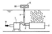
図1に示すように、本発明の曝気装置は、水中に設置される流水ポンプ1と、水上に設けられた磁石6を組み込んだ吸気部5と、流水ポンプ1に接続された吸水管7と減圧部として機能する通水管(ベンチュリ管)3と、この通水管3に接続された吸気管4と、イジェクター管2を備えた曝気水噴出管8とからなることを基本的な構成としている。図10に従来装置の一例を示すが、流水ポンプ1の排水管3は気泡発生器2に連通され、通水管3の中間部分に直上から送気管4が連通され、送気管4は送気ファン5から送られてくる大気Aを通水管3中の水流Wに噴出する。その結果、水流Wには大量の空気が含有され、気泡発生槽2から上昇する際に曝気効果が得られる点においては同様である。 As shown in FIG. 1, an aeration apparatus according to the present invention includes a running water pump 1 installed in water, an
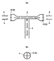
吸気部5は、図2に示すように、両端部が潰された扁平な吸気口5aを持つものや、図3に示すように、磁石6を内蔵したプロペラ10を備え、吸入した大気Aを吸気管4に送出する。通水管3は、吸気部5から吸入した大気Aを減圧及び加圧するベンチュリ効果を利用したもので、上流側から下流側に向かって拡径した長いテーパ部3aが形成され、このテーパ部3aの吐出側の端部(出口部分)が外向きラッパ状に形成されている。そして、外気Aを取り込んで気泡が混合された気液混合水AWを生成する。 As shown in FIG. 2, the
通水管3では、流水中に発生した気泡がテーパ状管内を通過する際に流速が速くなると共に減圧されて膨張し、その後は断面積が増加するにしたがって加圧されて収縮するが、この時に生じるせん断力によって気泡が細分化され微細気泡が発生する。 In the
図4乃至図5に示すように、さらに、水流はイジェクター管2を備えた曝気水噴出管8に導入され、その内壁面に沿って旋回流となり、発生した遠心力によりその中心部には吸引力が発生し、イジェクター管2の吸水口2aから貯水を吸引する。同時に旋回水流が大気を吸引し、管内部に突設された4本のスタティックミキサー13の流水誘導溝14により、水流が出口方向に下降、出口付近は下からの逆の吸引力とのせめぎ合いによってせん断され微細気泡となる。さらに、曝気水噴出管8出口周りの内外周面に形成した溝条11や砂地粗面12に旋回流を衝突させることで発生する乱流等で空洞現象(キャビテーション)が発生し、さらに微細化発泡を促進する。 Further, as shown in FIGS. 4 to 5, the water flow is introduced into the aeration
すなわち、水槽又は水域の貯水W中に設置される流水ポンプ1と、この流水ポンプ1の通水管3に接続され大気を吸入する吸気管4と、この通水管3の先端に取り付けられた曝気水噴出ノズル8とからなり、この曝気水噴出ノズル8外部から内部へ貯水を吸引する吸水部2aが設けられ、曝気水噴出ノズル8内部で旋回流を発生させると共に、発生した旋回流によって発生するよる減圧作用によるキャビテーション効果及び大気が加圧溶解された水流を減圧手段で圧力開放するベンチュリ効果により微細気泡を発生させ磁界を付与しながら磁化微細気泡含水流を吐出させる。 That is, the running water pump 1 installed in the water storage W of the water tank or the water area, the intake pipe 4 connected to the
また、図6乃至図8に示すように、供給水にN、Sの交番磁界を創出するための複数の永久磁石6とスタティックミキサー13を付し、吸気孔2bから大気を吸入して、そのキャビテーション作用により微細気泡を発生させる曝気水噴出ノズル9を貯水外部に取り付ける形式のものでもよい。この場合、水の磁化と同時に曝気を行って溶存酸素を補うことができ、とくに養殖池への供給水ノズルとして使用して有益である。尚、スタティックミキサー13に換えて図10に示すように、プロペラ10を使用して曝気を行ってもよく、所期の効果を得ることができる。 Also, as shown in FIGS. 6 to 8, a plurality of
尚、大気の吸気部としてはスタティックなインペラーに発生する負圧に向って空気が吸込まれる方式のものも利用でき、上記実施例のほか、インペラーに沿う円筒パイプの孔から空気が吸込まれるもの、パイプの通気口と通気可能に固定した中空箱型のインペラーの背面に気体噴出孔を穿設したもの、パイプに螺旋状に取付けたインペラーの回転方向の背面に沿う円筒パイプに螺旋状に気体噴出口を取付けたもの等も利用できる。 In addition, as an air intake portion, a method in which air is sucked in toward a negative pressure generated in a static impeller can be used, and in addition to the above embodiment, air is sucked from a hole in a cylindrical pipe along the impeller. A gas blowout hole on the back of a hollow box-type impeller fixed to the ventilation hole of the pipe, and a cylindrical pipe along the back in the rotational direction of the impeller attached to the pipe spirally. Those equipped with gas outlets can also be used.
このような自吸式の吸気部は、多量の大気Aを極微細気泡として流水中に発生させることができる。すなわち、流水中に強力な真空圧を発生させ、小さなエネルギーで大気を流水中に吸引させることができる。また、空気が極微細化されるため酸素の溶解効率を高めることができる。さらに、気泡は湖沼中の有機物等を表面に吸着する。 Such a self-priming intake part can generate a large amount of air A as ultrafine bubbles in running water. That is, it is possible to generate a strong vacuum pressure in the flowing water and to suck the atmosphere into the flowing water with a small energy. Moreover, since the air is made extremely fine, the dissolution efficiency of oxygen can be increased. Furthermore, the bubbles adsorb organic substances in the lake on the surface.
本発明で使用する永久磁石としては、例えば、ネオジウム系磁石、サマリウム系磁石などの表面3000ガウス以上の永久磁石が好ましい。 As the permanent magnet used in the present invention, for example, a permanent magnet having a surface of 3000 gauss or more such as a neodymium magnet or a samarium magnet is preferable.
本発明装置は、例えば、池や養殖場、下水、畜産廃水、広範囲な産業廃水に対する浄化処理を行うものである。すなわち、大気中のCO2を強制吸引して水中で溶解させ、海草や海藻、水草や水藻等の水生植物の炭酸同化作用を促進すると共に溶存酸素を増加させる。また、常磁性酸素による活性促進作用。磁石の同極同士を対向させることで生じる斥力により、大気中の酸素帯の無秩序磁性をさらに無秩序にして水中へ放出することで、溶存酸素を増大させ、好ましくは、7〜10PPMを確保することができる。さらに、窒素を強制的に水中に取り込むことで、水棲生物の窒素循環・代謝活性を促し、窒素同化作用を発生させ、水産生物の生体に必要な有機窒素成分(例えば、タンパク質・核酸)などの生成を促進する。The apparatus of the present invention performs purification treatment on, for example, ponds, farms, sewage, livestock wastewater, and a wide range of industrial wastewater. That is, CO 2 in the atmosphere is forcibly sucked and dissolved in water to promote the carbon assimilation action of aquatic plants such as seaweeds, seaweeds, aquatic plants and aquatic algae, and increase dissolved oxygen. Moreover, the activity promotion effect by paramagnetic oxygen. Dissolved oxygen is increased by releasing the disordered magnetism of the oxygen band in the atmosphere further disordered by the repulsive force generated by making the same poles of the magnets face each other, and preferably 7-10 PPM is secured. Can do. In addition, by forcibly incorporating nitrogen into water, it promotes the nitrogen cycle and metabolic activity of aquatic organisms, generates nitrogen assimilation, and organic nitrogen components (for example, proteins and nucleic acids) necessary for aquatic products. Promote generation.
1 流水ポンプ
2 イジェクター管
2a吸水孔
2b吸気孔
3 通水管(ベンチュリ管)
4 吸気管
5 吸気部
5a吸気口
6 永久磁石
7 吸水管
8 曝気水噴出管
9 曝気水噴出ノズル
10磁石内蔵プロペラ
11溝条
12砂地粗面
13スタティックミキサー
14流水誘導溝
W 水流
A 大気DESCRIPTION OF SYMBOLS 1
4
Claims (4)
Priority Applications (1)
| Application Number | Priority Date | Filing Date | Title |
|---|---|---|---|
| JP2016098280A JP6762467B2 (en) | 2016-04-21 | 2016-04-21 | Aeration device |
Applications Claiming Priority (1)
| Application Number | Priority Date | Filing Date | Title |
|---|---|---|---|
| JP2016098280A JP6762467B2 (en) | 2016-04-21 | 2016-04-21 | Aeration device |
Publications (2)
| Publication Number | Publication Date |
|---|---|
| JP2017192931A true JP2017192931A (en) | 2017-10-26 |
| JP6762467B2 JP6762467B2 (en) | 2020-09-30 |
Family
ID=60155800
Family Applications (1)
| Application Number | Title | Priority Date | Filing Date |
|---|---|---|---|
| JP2016098280A Active JP6762467B2 (en) | 2016-04-21 | 2016-04-21 | Aeration device |
Country Status (1)
| Country | Link |
|---|---|
| JP (1) | JP6762467B2 (en) |
Cited By (16)
| Publication number | Priority date | Publication date | Assignee | Title |
|---|---|---|---|---|
| CN109078514A (en) * | 2018-10-16 | 2018-12-25 | 上海行恒科技有限公司 | A kind of micro-nano bubble generator by water supply network pressure |
| CN109133238A (en) * | 2018-08-21 | 2019-01-04 | 薛光兵 | A kind of sanitary sewage aerator convenient for increasing working efficiency and energy self power generation |
| CN109539023A (en) * | 2018-11-16 | 2019-03-29 | 武汉理工大学 | A kind of LED radiator of venturi effect and transformation combining jet device |
| CN109529651A (en) * | 2018-12-06 | 2019-03-29 | 上海中兴科源环保科技有限公司 | A kind of micro-nano bubble water generator |
| JP2020110763A (en) * | 2019-01-11 | 2020-07-27 | 株式会社アクアトリム | Conduit device |
| CN111792740A (en) * | 2020-08-12 | 2020-10-20 | 福州水研环境科技有限公司 | High-concentration organic wastewater treatment device and treatment method |
| CN112499714A (en) * | 2020-11-10 | 2021-03-16 | 无锡海拓环保装备科技有限公司 | Rotational flow non-blocking releaser |
| JP2022025612A (en) * | 2020-07-29 | 2022-02-10 | 株式会社片山化学工業研究所 | Treatment method for oil-containing wastewater |
| CN114105328A (en) * | 2021-10-26 | 2022-03-01 | 北京爱尔斯生态环境工程有限公司 | Bottom distributed nano bubble aerator |
| CN114471986A (en) * | 2021-03-02 | 2022-05-13 | 北京航化节能环保技术有限公司 | Hydraulic ejector with high volume injection coefficient |
| WO2022107392A1 (en) * | 2020-11-17 | 2022-05-27 | 株式会社アネモス | Air diffuser and water treatment apparatus |
| CN114585343A (en) * | 2019-09-20 | 2022-06-03 | 松井嗣光 | Bathing device for thermotherapy |
| CN114642978A (en) * | 2022-03-22 | 2022-06-21 | 浙江一龙环保科技有限公司 | Suction type rotational flow microbubble generator |
| EP4052571A1 (en) * | 2021-03-04 | 2022-09-07 | Westall, Stephen Malcolm | Collapsible aerobic catalyzation apparatus for shipping-storage tank lid integration |
| CN115159660A (en) * | 2022-07-20 | 2022-10-11 | 湖南中森环境科技有限公司 | Submersible jet ozone aerator |
| CN115196761A (en) * | 2021-04-13 | 2022-10-18 | 宜维龙环境科技(苏州)有限公司 | Underwater movable aeration device, control method thereof, terminal and storage medium |
Citations (7)
| Publication number | Priority date | Publication date | Assignee | Title |
|---|---|---|---|---|
| JPH1028993A (en) * | 1996-07-12 | 1998-02-03 | Takashi Yamamoto | Aerator |
| JP2001300276A (en) * | 2000-04-24 | 2001-10-30 | Isao Endo | Bubble generating device |
| JP2011121002A (en) * | 2009-12-10 | 2011-06-23 | Takenaka Komuten Co Ltd | Nano bubble generator |
| JP2011167674A (en) * | 2010-02-22 | 2011-09-01 | Yoshikazu Shoda | Underwater aeration device |
| JP3191503U (en) * | 2014-04-01 | 2014-06-26 | 嗣光 松井 | Aeration equipment |
| JP2015195793A (en) * | 2014-04-01 | 2015-11-09 | 嗣光 松井 | Proliferation method and apparatus of euglena |
| WO2015186176A1 (en) * | 2014-06-02 | 2015-12-10 | 嗣光 松井 | Method and apparatus for manufacturing magnetized water |
-
2016
- 2016-04-21 JP JP2016098280A patent/JP6762467B2/en active Active
Patent Citations (7)
| Publication number | Priority date | Publication date | Assignee | Title |
|---|---|---|---|---|
| JPH1028993A (en) * | 1996-07-12 | 1998-02-03 | Takashi Yamamoto | Aerator |
| JP2001300276A (en) * | 2000-04-24 | 2001-10-30 | Isao Endo | Bubble generating device |
| JP2011121002A (en) * | 2009-12-10 | 2011-06-23 | Takenaka Komuten Co Ltd | Nano bubble generator |
| JP2011167674A (en) * | 2010-02-22 | 2011-09-01 | Yoshikazu Shoda | Underwater aeration device |
| JP3191503U (en) * | 2014-04-01 | 2014-06-26 | 嗣光 松井 | Aeration equipment |
| JP2015195793A (en) * | 2014-04-01 | 2015-11-09 | 嗣光 松井 | Proliferation method and apparatus of euglena |
| WO2015186176A1 (en) * | 2014-06-02 | 2015-12-10 | 嗣光 松井 | Method and apparatus for manufacturing magnetized water |
Cited By (26)
| Publication number | Priority date | Publication date | Assignee | Title |
|---|---|---|---|---|
| CN109133238B (en) * | 2018-08-21 | 2021-12-03 | 浙江环艺电子科技有限公司 | Aeration machine for domestic sewage convenient to increase work efficiency and can generate electricity |
| CN109133238A (en) * | 2018-08-21 | 2019-01-04 | 薛光兵 | A kind of sanitary sewage aerator convenient for increasing working efficiency and energy self power generation |
| CN109078514A (en) * | 2018-10-16 | 2018-12-25 | 上海行恒科技有限公司 | A kind of micro-nano bubble generator by water supply network pressure |
| CN109078514B (en) * | 2018-10-16 | 2023-10-17 | 上海行恒科技有限公司 | Micro-nano bubble generating device only by means of pressure of water supply pipe network |
| CN109539023B (en) * | 2018-11-16 | 2020-07-10 | 武汉理工大学 | L ED heat dissipation device for Venturi effect and improved synthetic jet device |
| CN109539023A (en) * | 2018-11-16 | 2019-03-29 | 武汉理工大学 | A kind of LED radiator of venturi effect and transformation combining jet device |
| CN109529651B (en) * | 2018-12-06 | 2024-02-23 | 上海中兴科源环保科技有限公司 | Micro-nano bubble water generator |
| CN109529651A (en) * | 2018-12-06 | 2019-03-29 | 上海中兴科源环保科技有限公司 | A kind of micro-nano bubble water generator |
| JP2020110763A (en) * | 2019-01-11 | 2020-07-27 | 株式会社アクアトリム | Conduit device |
| US20220323298A1 (en) * | 2019-09-20 | 2022-10-13 | Tsugumitsu Matsui | Bathing apparatus for thermotherapy |
| CN114585343A (en) * | 2019-09-20 | 2022-06-03 | 松井嗣光 | Bathing device for thermotherapy |
| JP2022025612A (en) * | 2020-07-29 | 2022-02-10 | 株式会社片山化学工業研究所 | Treatment method for oil-containing wastewater |
| JP7450882B2 (en) | 2020-07-29 | 2024-03-18 | 株式会社片山化学工業研究所 | Treatment method for oil-containing wastewater |
| CN111792740B (en) * | 2020-08-12 | 2024-05-03 | 福州水研环境科技有限公司 | High-concentration organic wastewater treatment device and treatment method |
| CN111792740A (en) * | 2020-08-12 | 2020-10-20 | 福州水研环境科技有限公司 | High-concentration organic wastewater treatment device and treatment method |
| CN112499714A (en) * | 2020-11-10 | 2021-03-16 | 无锡海拓环保装备科技有限公司 | Rotational flow non-blocking releaser |
| WO2022107392A1 (en) * | 2020-11-17 | 2022-05-27 | 株式会社アネモス | Air diffuser and water treatment apparatus |
| JP7414333B2 (en) | 2020-11-17 | 2024-01-16 | 株式会社アネモス | Air diffuser and water treatment equipment |
| CN114471986A (en) * | 2021-03-02 | 2022-05-13 | 北京航化节能环保技术有限公司 | Hydraulic ejector with high volume injection coefficient |
| EP4052571A1 (en) * | 2021-03-04 | 2022-09-07 | Westall, Stephen Malcolm | Collapsible aerobic catalyzation apparatus for shipping-storage tank lid integration |
| CN115196761A (en) * | 2021-04-13 | 2022-10-18 | 宜维龙环境科技(苏州)有限公司 | Underwater movable aeration device, control method thereof, terminal and storage medium |
| CN114105328A (en) * | 2021-10-26 | 2022-03-01 | 北京爱尔斯生态环境工程有限公司 | Bottom distributed nano bubble aerator |
| CN114642978B (en) * | 2022-03-22 | 2023-01-10 | 浙江一龙环保科技有限公司 | Suction type rotational flow microbubble generator |
| CN114642978A (en) * | 2022-03-22 | 2022-06-21 | 浙江一龙环保科技有限公司 | Suction type rotational flow microbubble generator |
| CN115159660A (en) * | 2022-07-20 | 2022-10-11 | 湖南中森环境科技有限公司 | Submersible jet ozone aerator |
| CN115159660B (en) * | 2022-07-20 | 2023-09-19 | 湖南中森环境科技有限公司 | Submersible jet ozone aerator |
Also Published As
| Publication number | Publication date |
|---|---|
| JP6762467B2 (en) | 2020-09-30 |
Similar Documents
| Publication | Publication Date | Title |
|---|---|---|
| JP6762467B2 (en) | Aeration device | |
| Khan et al. | Micro–nanobubble technology and water-related application | |
| KR101126320B1 (en) | Ventury tube type Nano Bubble proceded water Generator | |
| KR20160031562A (en) | Floating bioreactor system | |
| CN201058829Y (en) | Highly effective sewage treatment gas-mixing apparatus | |
| JP6383906B1 (en) | Fine bubble generator and water tank system using the same | |
| WO2018190550A1 (en) | Oxygen supply device for water quality improvement | |
| Serizawa | Fundamentals and applications of micro/nano bubbles | |
| KR101702345B1 (en) | Apparatus and Method for Removing Algae | |
| KR101171854B1 (en) | Apparatus for generating micro bubble | |
| KR101846253B1 (en) | Fluid treatment device | |
| JP2007325558A (en) | Method for water treatment and apparatus for water treatment | |
| JP2010162517A (en) | Water treatment apparatus and water treatment method | |
| CN108094302A (en) | Method for purifying water and system and earthy taste of fresh water fish minimizing technology | |
| KR101980335B1 (en) | Total layer circulation injection system for water purifying | |
| JP3191503U (en) | Aeration equipment | |
| JP6047518B2 (en) | Water quality improvement method and apparatus | |
| KR200300055Y1 (en) | Anion Oxygen and Magnetization Function | |
| CN105836872A (en) | Corona plasma activation method capable of improving mass transfer efficiency of ozone micro bubbles in water body | |
| KR20190110310A (en) | Upright single stage pump assembly for generating micro bubble | |
| US20140050801A1 (en) | Gas dissolving apparatus | |
| JP2009172469A (en) | Water treatment method and apparatus | |
| KR101599797B1 (en) | Water treatment method for sewage disposal tank | |
| KR101702346B1 (en) | Movable Apparatus and Method for Removing Floating Matter | |
| JP2004267868A (en) | System for dissolving/storing/supplying gas with line atomizer |
Legal Events
| Date | Code | Title | Description |
|---|---|---|---|
| A621 | Written request for application examination |
Free format text: JAPANESE INTERMEDIATE CODE: A621 Effective date: 20190319 |
|
| A977 | Report on retrieval |
Free format text: JAPANESE INTERMEDIATE CODE: A971007 Effective date: 20200129 |
|
| A131 | Notification of reasons for refusal |
Free format text: JAPANESE INTERMEDIATE CODE: A131 Effective date: 20200218 |
|
| A521 | Request for written amendment filed |
Free format text: JAPANESE INTERMEDIATE CODE: A523 Effective date: 20200317 |
|
| TRDD | Decision of grant or rejection written | ||
| A01 | Written decision to grant a patent or to grant a registration (utility model) |
Free format text: JAPANESE INTERMEDIATE CODE: A01 Effective date: 20200623 |
|
| A61 | First payment of annual fees (during grant procedure) |
Free format text: JAPANESE INTERMEDIATE CODE: A61 Effective date: 20200629 |
|
| R150 | Certificate of patent or registration of utility model |
Ref document number: 6762467 Country of ref document: JP Free format text: JAPANESE INTERMEDIATE CODE: R150 |
|
| R250 | Receipt of annual fees |
Free format text: JAPANESE INTERMEDIATE CODE: R250 |
|
| R250 | Receipt of annual fees |
Free format text: JAPANESE INTERMEDIATE CODE: R250 |