JP2017187465A - Supercontinuum-light-generating light source, supercontinuum-light generation method, multiphoton-excited fluorescence microscope, and multiphoton excitation method - Google Patents
Supercontinuum-light-generating light source, supercontinuum-light generation method, multiphoton-excited fluorescence microscope, and multiphoton excitation method Download PDFInfo
- Publication number
- JP2017187465A JP2017187465A JP2016178605A JP2016178605A JP2017187465A JP 2017187465 A JP2017187465 A JP 2017187465A JP 2016178605 A JP2016178605 A JP 2016178605A JP 2016178605 A JP2016178605 A JP 2016178605A JP 2017187465 A JP2017187465 A JP 2017187465A
- Authority
- JP
- Japan
- Prior art keywords
- light
- supercontinuum
- waveguide
- wavelength
- supercontinuum light
- Prior art date
- Legal status (The legal status is an assumption and is not a legal conclusion. Google has not performed a legal analysis and makes no representation as to the accuracy of the status listed.)
- Granted
Links
- 230000005284 excitation Effects 0.000 title claims abstract description 97
- 238000000034 method Methods 0.000 title claims description 26
- 239000000835 fiber Substances 0.000 claims abstract description 73
- 239000006185 dispersion Substances 0.000 claims abstract description 64
- 230000003287 optical effect Effects 0.000 claims abstract description 56
- 238000001228 spectrum Methods 0.000 claims abstract description 44
- 230000006835 compression Effects 0.000 claims description 66
- 238000007906 compression Methods 0.000 claims description 66
- 230000010355 oscillation Effects 0.000 claims description 28
- 230000001747 exhibiting effect Effects 0.000 claims description 17
- 238000001514 detection method Methods 0.000 claims description 13
- 230000008859 change Effects 0.000 claims description 6
- 238000006243 chemical reaction Methods 0.000 claims description 5
- 230000001678 irradiating effect Effects 0.000 claims description 5
- 239000000463 material Substances 0.000 claims description 5
- 239000000126 substance Substances 0.000 claims description 3
- 239000012472 biological sample Substances 0.000 abstract description 12
- 230000010287 polarization Effects 0.000 abstract description 10
- 238000010586 diagram Methods 0.000 description 21
- 230000000694 effects Effects 0.000 description 11
- 108010048367 enhanced green fluorescent protein Proteins 0.000 description 10
- 230000007246 mechanism Effects 0.000 description 8
- 230000002547 anomalous effect Effects 0.000 description 7
- 238000003384 imaging method Methods 0.000 description 7
- 230000003595 spectral effect Effects 0.000 description 6
- 238000002474 experimental method Methods 0.000 description 5
- 230000008901 benefit Effects 0.000 description 4
- 238000009826 distribution Methods 0.000 description 4
- 230000010354 integration Effects 0.000 description 4
- 239000013307 optical fiber Substances 0.000 description 4
- 238000004458 analytical method Methods 0.000 description 3
- 238000004364 calculation method Methods 0.000 description 3
- 238000004891 communication Methods 0.000 description 3
- 230000006378 damage Effects 0.000 description 3
- 230000007423 decrease Effects 0.000 description 3
- 230000006870 function Effects 0.000 description 3
- 238000004519 manufacturing process Methods 0.000 description 3
- 238000005259 measurement Methods 0.000 description 3
- 238000011160 research Methods 0.000 description 3
- 238000001069 Raman spectroscopy Methods 0.000 description 2
- 230000005540 biological transmission Effects 0.000 description 2
- 239000013078 crystal Substances 0.000 description 2
- 238000013461 design Methods 0.000 description 2
- 238000000605 extraction Methods 0.000 description 2
- 108091006047 fluorescent proteins Proteins 0.000 description 2
- 102000034287 fluorescent proteins Human genes 0.000 description 2
- 238000010521 absorption reaction Methods 0.000 description 1
- 230000003321 amplification Effects 0.000 description 1
- 238000005253 cladding Methods 0.000 description 1
- 230000000052 comparative effect Effects 0.000 description 1
- 230000001934 delay Effects 0.000 description 1
- 238000002845 discoloration Methods 0.000 description 1
- 238000005516 engineering process Methods 0.000 description 1
- 239000013305 flexible fiber Substances 0.000 description 1
- 238000007654 immersion Methods 0.000 description 1
- 239000007788 liquid Substances 0.000 description 1
- 239000004973 liquid crystal related substance Substances 0.000 description 1
- 230000009022 nonlinear effect Effects 0.000 description 1
- 238000003199 nucleic acid amplification method Methods 0.000 description 1
- 230000008569 process Effects 0.000 description 1
- 238000012545 processing Methods 0.000 description 1
- 230000001902 propagating effect Effects 0.000 description 1
- 239000010453 quartz Substances 0.000 description 1
- 229910052761 rare earth metal Inorganic materials 0.000 description 1
- 150000002910 rare earth metals Chemical class 0.000 description 1
- 238000002310 reflectometry Methods 0.000 description 1
- 239000004065 semiconductor Substances 0.000 description 1
- 238000000926 separation method Methods 0.000 description 1
- VYPSYNLAJGMNEJ-UHFFFAOYSA-N silicon dioxide Inorganic materials O=[Si]=O VYPSYNLAJGMNEJ-UHFFFAOYSA-N 0.000 description 1
- 238000010183 spectrum analysis Methods 0.000 description 1
- 238000003860 storage Methods 0.000 description 1
- 239000000758 substrate Substances 0.000 description 1
- 230000003685 thermal hair damage Effects 0.000 description 1
Images


Classifications
-
- G—PHYSICS
- G02—OPTICS
- G02F—OPTICAL DEVICES OR ARRANGEMENTS FOR THE CONTROL OF LIGHT BY MODIFICATION OF THE OPTICAL PROPERTIES OF THE MEDIA OF THE ELEMENTS INVOLVED THEREIN; NON-LINEAR OPTICS; FREQUENCY-CHANGING OF LIGHT; OPTICAL LOGIC ELEMENTS; OPTICAL ANALOGUE/DIGITAL CONVERTERS
- G02F1/00—Devices or arrangements for the control of the intensity, colour, phase, polarisation or direction of light arriving from an independent light source, e.g. switching, gating or modulating; Non-linear optics
- G02F1/35—Non-linear optics
- G02F1/365—Non-linear optics in an optical waveguide structure
-
- G—PHYSICS
- G01—MEASURING; TESTING
- G01N—INVESTIGATING OR ANALYSING MATERIALS BY DETERMINING THEIR CHEMICAL OR PHYSICAL PROPERTIES
- G01N21/00—Investigating or analysing materials by the use of optical means, i.e. using sub-millimetre waves, infrared, visible or ultraviolet light
- G01N21/62—Systems in which the material investigated is excited whereby it emits light or causes a change in wavelength of the incident light
- G01N21/63—Systems in which the material investigated is excited whereby it emits light or causes a change in wavelength of the incident light optically excited
- G01N21/64—Fluorescence; Phosphorescence
- G01N21/645—Specially adapted constructive features of fluorimeters
- G01N21/6456—Spatial resolved fluorescence measurements; Imaging
- G01N21/6458—Fluorescence microscopy
-
- G—PHYSICS
- G02—OPTICS
- G02B—OPTICAL ELEMENTS, SYSTEMS OR APPARATUS
- G02B21/00—Microscopes
- G02B21/16—Microscopes adapted for ultraviolet illumination ; Fluorescence microscopes
-
- G—PHYSICS
- G01—MEASURING; TESTING
- G01N—INVESTIGATING OR ANALYSING MATERIALS BY DETERMINING THEIR CHEMICAL OR PHYSICAL PROPERTIES
- G01N2201/00—Features of devices classified in G01N21/00
- G01N2201/06—Illumination; Optics
- G01N2201/069—Supply of sources
- G01N2201/0696—Pulsed
- G01N2201/0697—Pulsed lasers
-
- G—PHYSICS
- G02—OPTICS
- G02F—OPTICAL DEVICES OR ARRANGEMENTS FOR THE CONTROL OF LIGHT BY MODIFICATION OF THE OPTICAL PROPERTIES OF THE MEDIA OF THE ELEMENTS INVOLVED THEREIN; NON-LINEAR OPTICS; FREQUENCY-CHANGING OF LIGHT; OPTICAL LOGIC ELEMENTS; OPTICAL ANALOGUE/DIGITAL CONVERTERS
- G02F1/00—Devices or arrangements for the control of the intensity, colour, phase, polarisation or direction of light arriving from an independent light source, e.g. switching, gating or modulating; Non-linear optics
- G02F1/35—Non-linear optics
- G02F1/3528—Non-linear optics for producing a supercontinuum
-
- G—PHYSICS
- G02—OPTICS
- G02F—OPTICAL DEVICES OR ARRANGEMENTS FOR THE CONTROL OF LIGHT BY MODIFICATION OF THE OPTICAL PROPERTIES OF THE MEDIA OF THE ELEMENTS INVOLVED THEREIN; NON-LINEAR OPTICS; FREQUENCY-CHANGING OF LIGHT; OPTICAL LOGIC ELEMENTS; OPTICAL ANALOGUE/DIGITAL CONVERTERS
- G02F2201/00—Constructional arrangements not provided for in groups G02F1/00 - G02F7/00
- G02F2201/02—Constructional arrangements not provided for in groups G02F1/00 - G02F7/00 fibre
Abstract
Description
本願の発明は、スーパーコンティニウム光の生成技術に関するものであり、また蛍光顕微鏡の技術に関するものである。 The present invention relates to a supercontinuum light generation technique, and also relates to a fluorescence microscope technique.
高いピーク強度を有する狭帯域の超短パルスが非線形光学効果により広帯域化する現象は、スーパーコンティニウム光として知られている。特許文献1〜5は、従来知られたスーパーコンティニウム光生成光源を開示している。
スーパーコンティニウム光を生成して出射させる光源(スーパーコンティニウム光生成光源)は、超短パルス光を発振させるパルス光発振部と、非線形光学素子とを備えている。パルス発振部には超短パルスレーザー発振器が使用される場合が多く、非線形光学素子としては非線形ファイバのような導波路型のものが使用されることが多い。パルス光発振部から発振された超短パルス光が導波路に入射すると、導波路内を伝搬する際に自己位相変調、相互位相変調、四光波混合、ラマン散乱などの非線形光学効果により広帯域化し、スーパーコンティニウム光となって出射する。
The phenomenon in which a narrow-band ultrashort pulse having a high peak intensity broadens due to a nonlinear optical effect is known as supercontinuum light.
A light source that generates and emits supercontinuum light (supercontinuum light generation light source) includes a pulsed light oscillation unit that oscillates ultrashort pulsed light and a nonlinear optical element. In many cases, an ultrashort pulse laser oscillator is used for the pulse oscillating unit, and a waveguide type element such as a nonlinear fiber is often used as the nonlinear optical element. When ultrashort pulsed light oscillated from the pulsed light oscillator enters the waveguide, it propagates in the waveguide and becomes broadband due to nonlinear optical effects such as self-phase modulation, cross-phase modulation, four-wave mixing, and Raman scattering. It is emitted as super continuum light.
スーパーコンティニウム光は、主として光通信用の用途で実用化が期待されて研究されてきた。通信の大容量化のためにはマルチキャリア(多重伝送)化することが必要で、このための技術としてスーパーコンティニウム光の採用が検討されてきたが、マルチコア構造の光ファイバ等の開発もあって、スーパーコンティニウム光の実用化はそれほど進んでいない。
このような状況ではあるものの、レーザー光としての性質を保持しつつある程度広いスペクトル成分を有するスーパーコンティニウム光の優れた特性は、他の分野において好適に利用できる可能性があると考えられる。
本願発明は、上記の点を解決課題として為されたものであり、新たな用途に利用できるスーパーコンティニウム光を出射するスーパーコンティニウム光生成光源を提供することを目的としている。
Supercontinuum light has been researched with the expectation of practical application mainly for optical communication applications. In order to increase communication capacity, it is necessary to use multi-carrier (multiplex transmission), and the adoption of supercontinuum light as a technology for this purpose has been studied. Therefore, practical use of supercontinuum light has not progressed so much.
Although it is such a situation, it is considered that the excellent characteristics of supercontinuum light having a broad spectrum component while retaining the properties as laser light may be suitably used in other fields.
The present invention has been made with the above-described points as a solution, and an object of the present invention is to provide a supercontinuum light generation light source that emits supercontinuum light that can be used for new applications.
上記課題を解決するため、本願の請求項1記載の発明は、スーパーコンティニウム光を生成して出射させるスーパーコンティニウム光生成源であって、
超短パルス光を発振するパルス光発振部と、
パルス光発振部から発振された超短パルスレーザー光を非線形光学効果によりスーパーコンティニウム光に変換して出射させる導波路と
を備えており、
導波路は、850nm以上1550nm以下の波長域に含まれる少なくとも200nmの波長幅の帯域において連続したスペクトルのスーパーコンティニウム光となるよう超短パルスレーザー光を変換するものであり、
照射面で対象物を多光子励起可能となるようにスーパーコンティニウム光を出射させるものであるという構成を有する。
また、上記課題を解決するため、請求項2記載の発明は、前記請求項1の構成において、前記パルス光発振部及び前記導波路は、ピーク強度が1kW以上100kW以下であるスーパーコンティニウム光を出射させるものであるという構成を有する。
また、上記課題を解決するため、請求項3記載の発明は、前記請求項1又は2の構成において、850nm以上1550nm以下の波長域に含まれる少なくとも200nmの波長幅の帯域において3dB以内の波長平坦性を有するスーパーコンティニウム光を出射させるものであるという構成を有する。
また、上記課題を解決するため、請求項4記載の発明は、前記請求項1乃至3いずれかの構成において、前記パルス光発振部は、パルス幅が1ピコ秒以下であって且つ1000nm以上1100nm以下の波長域に中心波長を有する超短パルス光を発振するものであるという構成を有する。
また、上記課題を解決するため、請求項5記載の発明は、前記請求項1乃至4の構成において、前記導波路は、前記超短パルスレーザー光を1パルス内での波長の経時的変化が連続的であるスーパーコンティニウム光にするものであるという構成を有する。
また、上記課題を解決するため、請求項6記載の発明は、前記請求項1乃至5の構成において、前記導波路は、850nm以上1550nm以下の波長域において正常分散特性を示すファイバであるという構成を有する。
また、上記課題を解決するため、請求項7記載の発明は、前記請求項6の構成において、前記超短パルスレーザー光の中心波長が、前記正常分散特性を示すファイバの群速度分散スペクトルのピーク波長に対して±50nmの範囲内であるという構成を有する。
また、上記課題を解決するため、請求項8記載の発明は、前記請求項1乃至5いずれかの構成において、前記導波路から出射されたスーパーコンティニウム光を圧縮して当該スーパーコンティニウム光のピーク強度を増加させるパルス圧縮部を備えたという構成を有する。
また、上記課題を解決するため、請求項9記載の発明は、前記請求項6又は7の構成において、前記導波路から出射されたスーパーコンティニウム光を圧縮して当該スーパーコンティニウム光のピーク強度を増加させるパルス圧縮部を備えたという構成を有する。
また、上記課題を解決するため、請求項10記載の発明は、スーパーコンティニウム光を生成して出射させるスーパーコンティニウム光生成源であって、
超短パルス光を発振するパルス光発振部と、
パルス光発振部から発振された超短パルスレーザー光を非線形光学効果によりスーパーコンティニウム光に変換して出射させる導波路と
を備えており、
導波路は、850nm以上1550nm以下の波長域に含まれる少なくとも200nmの波長幅の帯域において連続したスペクトルのスーパーコンティニウム光となるよう超短パルスレーザー光を変換するものであり、
導波路から出射されたスーパーコンティニウム光を圧縮して当該スーパーコンティニウム光のピーク強度を増加させるパルス圧縮部を備えたという構成を有する。
また、上記課題を解決するため、請求項11記載の発明は、スーパーコンティニウム光を生成して出射させるスーパーコンティニウム光生成方法であって、
パルス光発振部により超短パルス光を発振するステップと、
パルス光発振部から発振された超短パルスレーザー光を導波路に入射させ、導波路における非線形光学効果によりスーパーコンティニウム光に変換して出射させるステップと
を備えており、
導波路は、850nm以上1550nm以下の波長域に含まれる少なくとも200nmの波長幅の帯域において連続したスペクトルのスーパーコンティニウム光となるよう超短パルスレーザー光を変換するものであり、
照射面で対象物を多光子励起可能となるようにスーパーコンティニウム光を出射させるという構成を有する。
また、上記課題を解決するため、請求項12記載の発明は、前記請求項11の構成において、ピーク強度が1kW以上100kW以下であるスーパーコンティニウム光を出射させるという構成を有する。
また、上記課題を解決するため、請求項13記載の発明は、前記請求項11又は12の構成において、850nm以上1550nm以下の波長域に含まれる少なくとも200nmの波長幅の帯域において3dB以内の波長平坦性を有するスーパーコンティニウム光を出射させるという構成を有する。
また、上記課題を解決するため、請求項14記載の発明は、前記請求項11乃至13いずれかの構成において、前記パルス光発振部から発振される超短パルス光は、パルス幅が1ピコ秒以下であって且つ1000nm以上1100nm以下の波長域に中心波長を有する。
また、上記課題を解決するため、請求項15記載の発明は、前記請求項11乃至14いずれかの構成において、前記導波路は、前記超短パルスレーザー光を1パルス内での波長の経時的変化が連続的であるスーパーコンティニウム光にするものであるという構成を有する。
また、上記課題を解決するため、請求項16記載の発明は、前記請求項11乃至15いずれかの構成において、前記導波路は、850nm以上1550nm以下の波長域において正常分散特性を示すファイバであるという構成を有する。
また、上記課題を解決するため、請求項17記載の発明は、前記請求項16構成において、前記超短パルスレーザー光の中心波長が、前記正常分散特性を示すファイバの群速度分散スペクトルのピーク波長に対して±50nmの範囲内であるという構成を有する。
また、上記課題を解決するため、請求項18記載の発明は、前記請求項11乃至15いずれかの構成において、前記導波路から出射されたスーパーコンティニウム光を圧縮して当該スーパーコンティニウム光のピーク強度を増加させるという構成を有する。
また、上記課題を解決するため、請求項19記載の発明は、前記請求項16又は17の構成において、前記導波路から出射されたスーパーコンティニウム光を圧縮して当該スーパーコンティニウム光のピーク強度を増加させるという構成を有する。
また、上記課題を解決するため、請求項20記載の発明は、スーパーコンティニウム光を生成して出射させるスーパーコンティニウム光生成方法であって、
パルス光発振部により超短パルス光を発振するステップと、
パルス光発振部から発振された超短パルスレーザー光を導波路に入射させ、導波路における非線形光学効果によりスーパーコンティニウム光に変換して出射させるステップと
を備えており、
導波路は、850nm以上1550nm以下の波長域に含まれる少なくとも200nmの波長幅の帯域において連続したスペクトルのスーパーコンティニウム光となるよう超短パルスレーザー光を変換するものであり、
導波路から出射されたスーパーコンティニウム光を圧縮して当該スーパーコンティニウム光のピーク強度を増加させるという構成を有する。
また、上記課題を解決するため、請求項21記載の発明は、前記請求項1乃至10いずれかに記載のスーパーコンティニウム光生成光源を備えた多光子励起蛍光顕微鏡であって、
前記導波路から出射されたスーパーコンティニウム光を対象物上に照射するための光学系と、
対象物を当該スーパーコンティニウム光で多光子励起したときに放出される蛍光を検出する検出部とを備えているという構成を有する。
また、上記課題を解決するため、請求項22記載の発明は、生成されたスーパーコンティニウム光により蛍光物質を多光子励起して蛍光を発生させる多光子励起方法であって、
パルス光発振部により超短パルス光を発振する発振ステップと、
パルス光発振部から発振された超短パルスレーザー光を導波路に入射させ、導波路における非線形光学効果によりスーパーコンティニウム光に変換して出射させる変換ステップと、
出射したスーパーコンティニウム光をパルス圧縮してピーク強度を増加させる圧縮ステップと、
圧縮ステップによりピーク強度を増加させたスーパーコンティニウム光の全部又は一部を蛍光物質に照射して蛍光物質を多光子励起する照射ステップと
を備えており、
変換ステップは、850nm以上1550nm以下の波長域に含まれる少なくとも200nmの波長幅の帯域において連続したスペクトルのスーパーコンティニウム光となるよう導波路により超短パルスレーザー光を変換するステップであるという構成を有する。
In order to solve the above problem, the invention according to
A pulsed light oscillator that oscillates ultrashort pulsed light;
A waveguide that converts the ultrashort pulse laser light oscillated from the pulsed light oscillation unit into supercontinuum light by a nonlinear optical effect and emits it.
The waveguide converts ultrashort pulse laser light so as to be supercontinuum light having a continuous spectrum in a wavelength band of at least 200 nm included in a wavelength range of 850 nm to 1550 nm,
It has a configuration in which supercontinuum light is emitted so that an object can be excited by multiphotons on the irradiation surface.
In order to solve the above-mentioned problem, the invention according to
In order to solve the above-mentioned problem, the invention according to
In order to solve the above problem, according to a fourth aspect of the present invention, in the configuration according to any one of the first to third aspects, the pulsed light oscillation section has a pulse width of 1 picosecond or less and 1000 nm to 1100 nm. It has a configuration that oscillates ultrashort pulsed light having a center wavelength in the following wavelength range.
In order to solve the above problem, the invention according to
In order to solve the above problem, the invention according to
In order to solve the above-mentioned problem, the invention according to
In order to solve the above problem, the invention according to
In order to solve the above problem, the invention according to
In order to solve the above problem, the invention according to
A pulsed light oscillator that oscillates ultrashort pulsed light;
A waveguide that converts the ultrashort pulse laser light oscillated from the pulsed light oscillation unit into supercontinuum light by a nonlinear optical effect and emits it.
The waveguide converts ultrashort pulse laser light so as to be supercontinuum light having a continuous spectrum in a wavelength band of at least 200 nm included in a wavelength range of 850 nm to 1550 nm,
The super-continuum light emitted from the waveguide is compressed to increase the peak intensity of the super-continuum light.
In order to solve the above problem, the invention according to
Oscillating ultrashort pulsed light by the pulsed light oscillation unit;
A step of causing the ultra-short pulse laser light oscillated from the pulsed light oscillation unit to enter the waveguide, converting it to supercontinuum light by a nonlinear optical effect in the waveguide, and emitting the step.
The waveguide converts ultrashort pulse laser light so as to be supercontinuum light having a continuous spectrum in a wavelength band of at least 200 nm included in a wavelength range of 850 nm to 1550 nm,
It has a configuration in which supercontinuum light is emitted so as to enable multiphoton excitation of the object on the irradiation surface.
In order to solve the above-mentioned problem, the invention according to
In order to solve the above-mentioned problem, the invention according to
In order to solve the above problem, according to a fourteenth aspect of the present invention, in the configuration of any one of the eleventh to thirteenth aspects, the ultrashort pulsed light oscillated from the pulsed light oscillation unit has a pulse width of 1 picosecond. And has a central wavelength in a wavelength region of 1000 nm to 1100 nm.
In order to solve the above-mentioned problem, according to a fifteenth aspect of the present invention, in the configuration according to any one of the eleventh to fourteenth aspects, the waveguide includes a wavelength of the ultrashort pulse laser beam with time in one pulse. It has a configuration in which the supercontinuum light changes continuously.
In order to solve the above-described problem, the invention according to claim 16 is the fiber according to any one of
In order to solve the above problem, the invention according to claim 17 is the configuration according to claim 16, wherein the center wavelength of the ultrashort pulse laser beam is a peak wavelength of a group velocity dispersion spectrum of a fiber exhibiting the normal dispersion characteristic. With respect to the range of ± 50 nm.
In order to solve the above-mentioned problem, the invention according to claim 18 is the structure according to any one of
In order to solve the above problem, the invention according to claim 19 is the configuration of claim 16 or 17, wherein the peak intensity of the supercontinuum light is compressed by compressing the supercontinuum light emitted from the waveguide. It has the structure of increasing.
In order to solve the above problem, the invention according to
Oscillating ultrashort pulsed light by the pulsed light oscillation unit;
A step of causing the ultra-short pulse laser light oscillated from the pulsed light oscillation unit to enter the waveguide, converting it to supercontinuum light by a nonlinear optical effect in the waveguide, and emitting the step.
The waveguide converts ultrashort pulse laser light so as to be supercontinuum light having a continuous spectrum in a wavelength band of at least 200 nm included in a wavelength range of 850 nm to 1550 nm,
The supercontinuum light emitted from the waveguide is compressed to increase the peak intensity of the supercontinuum light.
In order to solve the above problem, the invention according to claim 21 is a multiphoton excitation fluorescence microscope comprising the supercontinuum light generation light source according to any one of
An optical system for irradiating the object with supercontinuum light emitted from the waveguide;
And a detection unit that detects fluorescence emitted when the target is multiphoton excited with the supercontinuum light.
In order to solve the above-mentioned problem, the invention according to claim 22 is a multiphoton excitation method for generating fluorescence by multiphoton excitation of a fluorescent substance with generated supercontinuum light,
An oscillation step of oscillating ultrashort pulsed light by the pulsed light oscillation unit;
A conversion step of causing the ultrashort pulse laser light oscillated from the pulsed light oscillation unit to be incident on the waveguide, converting it into supercontinuum light by a nonlinear optical effect in the waveguide, and
A compression step for increasing the peak intensity by pulse compression of the emitted supercontinuum light; and
An irradiation step of irradiating the fluorescent material with all or part of the supercontinuum light whose peak intensity is increased by the compression step and exciting the fluorescent material with multiphotons,
The conversion step is a step of converting the ultrashort pulse laser light by the waveguide so as to become supercontinuum light having a continuous spectrum in a wavelength band of at least 200 nm included in a wavelength range of 850 nm to 1550 nm. Have.
以下に説明する通り、本願の請求項1又は11記載の発明によれば、850nm以上1550nm以下の波長域に含まれる少なくとも200nmの波長幅の帯域において連続したスペクトルのスーパーコンティニウム光が出射され、当該スーパーコンティニウム光は対象物を多光子励起可能であるので、多光子励起を利用した対象物の蛍光観察や計測等に好適に使用することができる。
また、請求項2又は12記載の発明によれば、上記効果に加え、ピーク強度が1kW以上100kW以下であるので、生体試料の蛍光観察に好適に使用することができる。
また、請求項3又は13記載の発明によれば、上記効果に加え、3dB以内の波長平坦性を有するので、より汎用性の高いスーパーコンティニウム光生成光源となる。
また、請求項4又は14記載の発明によれば、上記効果に加え、高い波長平坦性を容易に実現することができる。
また、請求項5又は15記載の発明によれば、線形チャープであるスーパーコンティニウム光が生成されるので、その特性を種々の用途に活かすことができる。
また、請求項6又は16記載の発明によれば、上記効果に加え、850〜1550nmの波長域のスーパーコンティニウム光が容易に生成できたり、ピーク強度の大きなスーパーコンティニウム光を容易に生成できたりする効果が得られる。
また、請求項7又は請求項17記載の発明によれば、上記効果に加え、超短パルスレーザー光の中心波長が、正常分散特性を示すファイバの群速度分散スペクトルのピーク波長に対して±50nmの範囲内であるので、線形チャープであるスーパーコンティニウム光をより容易に得ることができる。
また、請求項8、10、18又は20記載の発明によれば、上記効果に加え、導波路から出射されたスーパーコンティニウム光を圧縮して当該スーパーコンティニウム光のピーク強度を増加させるので、高いピーク強度のスーパーコンティニウム光を得ることができる。
また、請求項9又は請求項19記載の発明によれば、上記効果に加え、導波路から出射されたスーパーコンティニウム光を圧縮して当該スーパーコンティニウム光のピーク強度を増加させるので、高いピーク強度のスーパーコンティニウム光を得ることができる。この際、正常分散特性を示すファイバにより線形チャープとされたスーパーコンティニウム光をパルス圧縮するので、より容易に圧縮を行うことができる。
また、請求項21記載の発明によれば、上記効果に加え、850nm以上1550nm以下の波長域において、異なる吸収波長をもつ複数の蛍光タンパクを同時に多光子励起することが一台のレーザーで可能となる。なお、当然ながら波長調節機構を設け、任意の波長を切り出して単色励起の多光子励起蛍光観察を行うこともできる。従来、多色同時励起には複数のレーザーを必要としたため、本発明に依れば省スペースで汎用性の高い多光子励起蛍光顕微鏡を実現できる。
As described below, according to the invention described in
Further, according to the invention described in
According to the invention described in
Moreover, according to the invention of
According to the invention described in
According to the invention of
According to the invention of
According to the invention of
According to the invention of
According to the invention described in claim 21, in addition to the above effect, a single laser can simultaneously excite a plurality of fluorescent proteins having different absorption wavelengths in a wavelength region of 850 nm to 1550 nm. Become. Of course, it is also possible to provide a wavelength adjustment mechanism, cut out an arbitrary wavelength, and perform multi-photon excitation fluorescence observation of monochromatic excitation. Conventionally, since multiple lasers are required for simultaneous multicolor excitation, according to the present invention, a multi-photon excitation fluorescence microscope that is space-saving and highly versatile can be realized.
次に、本願発明を実施するための形態(以下、実施形態)について説明する。図1は、第一の実施形態のスーパーコンティニウム光(以下、SC光という)生成光源の概略図である。尚、以下の説明では、実施形態のSC光生成光源の動作に関する説明を含むが、この説明は、SC光生成方法の発明の実施形態の説明に相当している。
この実施形態のSC光生成光源の大きな特徴点は、対象物を多光子励起可能な光子密度以上となる光子密度のSC光を出射するものとなっている点である。即ち、実施形態のSC光生成光源は、多光子励起用の光源として構成されたものとなっている。
このような実施形態の多光子励起用のSC光生成光源の好ましい利用例として、多光子励起蛍光顕微鏡が想定されている。
Next, modes for carrying out the present invention (hereinafter referred to as embodiments) will be described. FIG. 1 is a schematic diagram of a supercontinuum light (hereinafter referred to as SC light) generation light source according to the first embodiment. In addition, although the following description includes the description regarding operation | movement of the SC light generation light source of embodiment, this description is equivalent to description of embodiment of invention of the SC light generation method.
A major feature of the SC light generation light source of this embodiment is that it emits SC light having a photon density equal to or higher than a photon density capable of multiphoton excitation of an object. That is, the SC light generation light source of the embodiment is configured as a light source for multiphoton excitation.
A multi-photon excitation fluorescence microscope is assumed as a preferable application example of the SC light generation light source for multi-photon excitation of such an embodiment.
蛍光顕微鏡は、対象物に励起光を照射し、発生する蛍光を捉えることで対象物を観察するタイプの顕微鏡であり、バイオ研究や生体試料の観察等の分野において特に重要な技術となっている。蛍光顕微鏡の場合、対象物のうちの観察したい部分のみ色づけして観察したり、細胞内の動きを細胞が生きている状態で観察したりすることも可能であるという特長点を有する。 The fluorescence microscope is a type of microscope that observes an object by irradiating the object with excitation light and capturing generated fluorescence, and is a particularly important technique in fields such as bio research and observation of biological samples. . In the case of a fluorescence microscope, only a portion of an object to be observed is colored and observed, or the movement inside the cell can be observed in a state where the cell is alive.
このような蛍光顕微鏡の分野において、近年、二光子励起蛍光顕微鏡の技術が開発されている。励起光による蛍光放出は、通常、一つの光子が分子に吸収されて生じるが、二光子励起は、二つの光子を同時に吸収させて励起し、蛍光を放出させる。理論的には三個以上の光子を同時に吸収させて励起することも可能であり、多数の光子を同時に吸収させて励起する蛍光顕微鏡は、多光子励起蛍光顕微鏡と呼ばれる。多光子励起蛍光顕微鏡のより詳しい内容は、例えば非特許文献1に開示されている。
In the field of such a fluorescence microscope, in recent years, a technique of a two-photon excitation fluorescence microscope has been developed. Fluorescence emission by excitation light usually occurs when one photon is absorbed by a molecule, but two-photon excitation absorbs two photons at the same time and excites them to emit fluorescence. Theoretically, it is possible to simultaneously absorb and excite three or more photons, and the fluorescence microscope that absorbs and excites many photons at the same time is called a multi-photon excitation fluorescence microscope. More detailed contents of the multiphoton excitation fluorescence microscope are disclosed in
多光子励起蛍光顕微鏡が他の蛍光顕微鏡に比べて優れている点は幾つかあるが、その一つが波長分離が容易であるという点である。蛍光顕微鏡においては、発生する蛍光を励起波長の光から分離して蛍光のみを観察する必要があるが、通常の蛍光顕微鏡、即ち一光子で励起する蛍光顕微鏡の場合、蛍光の波長と励起波長とが近い場合が多く、分離が難しい。シャープカットフィルタ等を使用して励起光を除去し、蛍光のみを取り出すようにするが、蛍光の波長域が励起光の波長域と一部重なっている場合が多く、励起光を取り除く際に蛍光まで取り除くことになってしまう場合が多い。このため、蛍光を十分な強度で捉えることができない。一方、二光子励起の場合、励起波長が発生する蛍光波長の2倍になるため、シャープカットフィルタ等で容易に分離が可能であり、発生する蛍光を損なうことなく観察が可能である。 The multiphoton excitation fluorescence microscope has several advantages over other fluorescence microscopes, one of which is that wavelength separation is easy. In a fluorescence microscope, it is necessary to separate the generated fluorescence from the light of the excitation wavelength and observe only the fluorescence. In the case of a normal fluorescence microscope, that is, a fluorescence microscope excited by one photon, the fluorescence wavelength and the excitation wavelength are Are often close and difficult to separate. The excitation light is removed using a sharp cut filter or the like so that only the fluorescence is extracted. However, in many cases, the fluorescence wavelength region partially overlaps with the excitation light wavelength region. In many cases, it will be removed. For this reason, fluorescence cannot be captured with sufficient intensity. On the other hand, in the case of two-photon excitation, since the excitation wavelength is twice the generated fluorescence wavelength, it can be easily separated by a sharp cut filter or the like and can be observed without impairing the generated fluorescence.
多光子励起蛍光顕微鏡のもう一つの優位性は、深さ方向の任意の位置で蛍光観察が可能という点である。多光子励起は、非常に短い時間幅(10−16秒程度、実質的に同時)に二以上の光子が蛍光分子に衝突する必要があり、そのためには、非常に高い光子密度が必要である。したがって、励起光をある程度透過する対象物において対象物の内部で励起光を集光した場合、集光点でのみ多光子励起が生じ、その点での発生蛍光のみを観察することができる。そして、集光位置を変更することで、深さ方向の任意の位置で観察を行うことができる。このように、必然的に共焦点顕微鏡のピンホールの効果が得られ、ピンホールが不要であるため発生蛍光のロスも生じない。この点は、例えば生体試料の組織内部の状態を観察する場合等において特にメリットとなる。
多光子励起を実現するには、光子密度を時間的及び空間的に高める必要がある。このため、光源には、フェムト秒のようなごく短い時間しか発光しない超短パルスレーザー発振器が使用される。レーザー発振器が発生させる全強度を短い時間に集中させることで、多光子励起に必要とされる高い光子密度を実現するためである。
Another advantage of the multiphoton excitation fluorescence microscope is that fluorescence observation is possible at an arbitrary position in the depth direction. Multiphoton excitation requires that two or more photons collide with fluorescent molecules in a very short time span (approximately 10-16 seconds, substantially simultaneously), which requires a very high photon density. . Therefore, when the excitation light is condensed inside the object in the object that transmits the excitation light to some extent, multiphoton excitation occurs only at the condensing point, and only generated fluorescence at that point can be observed. And it can observe in the arbitrary positions of a depth direction by changing a condensing position. Thus, the pinhole effect of the confocal microscope is inevitably obtained, and the loss of generated fluorescence does not occur because the pinhole is unnecessary. This point is particularly advantageous when, for example, observing the internal state of a tissue of a biological sample.
In order to realize multiphoton excitation, it is necessary to increase the photon density temporally and spatially. For this reason, an ultrashort pulse laser oscillator that emits light for a very short time such as femtosecond is used as the light source. This is to achieve a high photon density required for multiphoton excitation by concentrating the total intensity generated by the laser oscillator in a short time.
このような多光子励起蛍光顕微鏡は、一部に実用化されているものの、幾つかの課題があり、それ程普及していない。一つには、観察条件の自由度が極めて低いことである。
周知のように、蛍光分子によって励起波長は異なり、また発生する蛍光の波長も異なる。したがって、異なる試料を観察する場合、殆どの場合、異なる波長の励起光を照射する必要がある。従来の多光子励起蛍光顕微鏡において、異なる波長の励起光を照射するためには、出射波長の異なる超短パルスレーザー発振器が必要になるから、理屈の上では、観察する蛍光分子の種類毎に超短パルスレーザー発振器が必要になる。周知のように超短パルスレーザー発振器は非常に高価な機器であり、蛍光分子の種類毎に超短パルスレーザー発振器を備えることは、実現可能な範囲を遙かに超えている。
Although such a multiphoton excitation fluorescence microscope has been put into practical use in part, there are some problems and it has not become so popular. For one thing, the degree of freedom in viewing conditions is extremely low.
As is well known, the excitation wavelength varies depending on the fluorescent molecule, and the wavelength of the generated fluorescence also varies. Therefore, when observing different samples, in most cases, it is necessary to irradiate excitation light having different wavelengths. In order to irradiate excitation light with different wavelengths in a conventional multiphoton excitation fluorescence microscope, an ultrashort pulse laser oscillator with different emission wavelengths is required. A short pulse laser oscillator is required. As is well known, an ultrashort pulse laser oscillator is a very expensive device, and it is far beyond the feasible range to provide an ultrashort pulse laser oscillator for each type of fluorescent molecule.
特許文献6には、三つの異なる蛍光分子を観察するため、二台の超短パルスレーザー発振器を用いた多光子励起蛍光顕微鏡が開示されている。この技術によれば、観察される蛍光分子の種類よりも一つ少ない超短パルスレーザーの台数で済むものの、それでも二台の超短パルスレーザー発振器が必要であり、コストの問題は大きい。
また、特許文献6の多光子励起蛍光顕微鏡では、二つの超短パルスレーザー発振器から発振される超短パルスレーザー光を集光スポットにおいて時間的及び空間的に重ね合わせる必要がある。非常に複雑で大がかりな機構や制御系が必要になり、コスト上の問題に加え、調整作業の困難性も問題となる。
In the multiphoton excitation fluorescence microscope of
実用化されている一部の多光子励起蛍光顕微鏡には、超短パルスレーザー発振器に対して波長調整機構を設けた構成(チューナブルレーザーの構成)が採用されているものもある。しかしながら、この種の波長調整機構は、OPO(光パラメトリック発振器)のような非線形光学素子を使用した機構であり、位相整合等の波長調整にかなりの労力を要する問題がある。
発明者は、このような多光子励起蛍光顕微鏡において、SC光を採用することで上記各課題をクリアすることができるのではないかと考え、鋭意研究を行った。実施形態のSC光生成光源は、この研究の成果に基づいている。
Some of the multi-photon excitation fluorescence microscopes that have been put to practical use employ a configuration (tunable laser configuration) in which a wavelength adjustment mechanism is provided for an ultrashort pulse laser oscillator. However, this type of wavelength adjustment mechanism uses a non-linear optical element such as an OPO (Optical Parametric Oscillator) and has a problem that requires considerable labor for wavelength adjustment such as phase matching.
The inventor thought that the above-mentioned problems could be solved by adopting SC light in such a multi-photon excitation fluorescence microscope, and conducted earnest research. The SC light generation light source of the embodiment is based on the results of this research.
より具体的に説明すると、図1に示す実施形態のSC光生成光源は、超短パルス光を発振するパルス光発振部1と、非線形光学効果を生じさせる導波路2とを備えている。
パルス光発振部1には、超短パルスレーザー発振器が使用される。この超短パルスレーザー発振器は、フェムト秒オーダーの超短パルスを発振するものであり、より好ましくは1ps(ピコ秒)以下のパルス幅のものが使用される。超短パルスレーザー発振器の出射光の中心波長は、1000〜1100nm程度であることが好ましい。具体的には、Ybのような希土類ドープファイバを用いた超短パルスファイバレーザー発振器、半導体レーザーで励起されるYb:KYWのようなYb系結晶を用いた超短パルスレーザー発振器が使用される。
More specifically, the SC light generation light source of the embodiment shown in FIG. 1 includes a pulsed
An ultrashort pulse laser oscillator is used for the pulsed
導波路2は、非線形光学効果により超短パルスからSC光を生成するもの(非線形導波路)である。この実施形態では光ファイバが導波路2として使用されており、特に高非線形ファイバが導波路2として好適に使用される。導波路2としての非線形ファイバは、ループ状とされたフレキシブルなものであったり、又はロッド状のものであったりし得る。
この実施形態では、パルス光発振部1と導波路2との間に偏光制御素子3が設けられている。偏光制御素子3は、導波路2の非線形光学効果をより高めるためのものであり、超短パルス光を導波路2の特性に応じて所望の偏光状態として導波路2に入射させるためのものである。偏光制御素子3としては、1/2波長板や1/4波長板といった波長板が使用されている。偏光制御素子3は、超短パルスレーザー光を導波路2の特性に応じて所定の向きの直線偏光光に変換して導波路2に入射させる。本実施形態では直線偏光を用いて説明するが、この限りではない。
The
In this embodiment, a
このような実施形態のSC光生成光源は、850〜1550nmの波長域に含まれる少なくとも200nmの波長幅の帯域において連続したSC光を出射するものとなっている。そして、実施形態のSC光生成光源は、より好ましくは、時間ピーク強度が1kW以上であるSC光を出射するものとなっている。これらの点について、より具体的な例を取りあげて説明する。
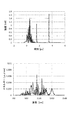
図2は、図1に示す実施形態のSC光生成光源の一例(実施例)について、出射された光をスペクトルアナライザで分析した結果を示す図である。図2の(1)は、パルス波形即ち時間経過に伴う出射光の強度(波長積分)を示した図である。また、図2の(2)は、(1)のパルス波形の出射光のスペクトル分布を示した図であり、1パルスでの各波長のエネルギー(時間積分)を波長の大きさで規格化して示した図である。
The SC light generation light source of such an embodiment emits continuous SC light in a band having a wavelength width of at least 200 nm included in the wavelength range of 850 to 1550 nm. The SC light generation light source of the embodiment more preferably emits SC light having a time peak intensity of 1 kW or more. These points will be described using more specific examples.
FIG. 2 is a diagram illustrating a result of analyzing emitted light by a spectrum analyzer with respect to an example (example) of the SC light generation light source of the embodiment illustrated in FIG. 1. (1) of FIG. 2 is a diagram showing a pulse waveform, that is, an intensity (wavelength integration) of emitted light with time. FIG. 2 (2) is a diagram showing the spectral distribution of the emitted light having the pulse waveform of (1). The energy (time integration) of each wavelength in one pulse is normalized by the size of the wavelength. FIG.
この例では、パルス光発振部1には、出射するレーザー光の中心波長1045nm、パルス幅は200fs(フェムト秒)のYb系結晶を用いたパルスレーザー発振器が使用されている。図2(1)に示すように、導波路2からの出射光の時間ピーク強度は、2kW程度となっている。また、図2(2)に示すように、出射光は、800〜1400nm程度の範囲に亘って連続しており、SC光となっていることが確認された。
In this example, a pulsed laser oscillator using a Yb-based crystal having a center wavelength of 1045 nm and a pulse width of 200 fs (femtosecond) is used for the pulsed
このような実施形態のSC光生成光源は、出射されるSC光の波長平坦性が3dB以下となっている。波長平坦性とは、各スペクトルの強度の均一性のことであり、スペクトル強度の凹凸の小ささを意味する。3dB以下とは、最も強度の低い波長の当該強度に対して、最も強度の高い波長の強度が3dB以内になっているということである。図2(2)に示すように、実施例1のSC光生成光源によるSC光は、850nm程度から1250nm程度の範囲での強度の凹凸は3dB以内となっている。 In the SC light generation light source of such an embodiment, the wavelength flatness of the emitted SC light is 3 dB or less. Wavelength flatness is the uniformity of the intensity of each spectrum and means the smallness of the unevenness of the spectrum intensity. 3 dB or less means that the intensity of the highest intensity wavelength is within 3 dB with respect to the intensity of the lowest intensity wavelength. As shown in FIG. 2 (2), the SC light generated by the SC light generation light source of Example 1 has an intensity unevenness in the range of about 850 nm to about 1250 nm within 3 dB.
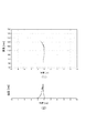
波長平坦性3dB以内という点について、別の実施例を挙げてさらに詳しく説明する。図3は、別の二つの実施例(実施例2,実施例3)のSC光生成光源の出射光の分析結果について示した図である。
図3(1)には、実施例2として、パルス光発振部1に、中心波長1100nm、パルス幅1psの光パラメトリック増幅システム(OPA)を用いた例が示されている。この例では、850〜1550nm程度の波長範囲において3dB以内の波長平坦性が得られている。
また、図3(2)には、実施例3として、パルス光発振部1に中心波長1030nm、パルス幅170fsのYbドープファイバレーザー発振器を用いた例が示されている。この例では、950〜1150nm程度の波長範囲において3dB以内の波長平坦性が得られている。
The point that the wavelength flatness is within 3 dB will be described in more detail with another example. FIG. 3 is a diagram showing the analysis results of the emitted light of the SC light generation light source of two other examples (Examples 2 and 3).
FIG. 3 (1) shows an example in which an optical parametric amplification system (OPA) having a center wavelength of 1100 nm and a pulse width of 1 ps is used for the pulsed
FIG. 3B shows an example in which a Yb-doped fiber laser oscillator having a center wavelength of 1030 nm and a pulse width of 170 fs is used for the pulsed
このような高い波長平坦性を有する実施形態のSC光生成光源の優れた性能は、使用された導波路2の特性が大きく影響している。以下、この点について説明する。
実施形態のSC光生成光源は、出射波長の範囲内において正常分散特性を示す非線形ファイバを導波路2として使用している。図4は、実施形態のSC光生成光源が備える導波路2の波長分散特性を示した図である。
波長分散特性は光ファイバの基本的特性の一つであり、通信の分野では波長分散を小さくすることが重要であるが、SC光生成に用いる非線形光ファイバは、波長分散を非線形光学効果により逆に高めることで広帯域化を図るものであるといえる。このような波長分散特性には、正常分散特性と異常分散特性とが知られている。
The excellent performance of the SC light generation light source of the embodiment having such high wavelength flatness is greatly influenced by the characteristics of the used
The SC light generation light source of the embodiment uses a nonlinear fiber exhibiting normal dispersion characteristics as the
Chromatic dispersion characteristics are one of the fundamental characteristics of optical fibers. In the field of communications, it is important to reduce chromatic dispersion. However, nonlinear optical fibers used for SC light generation reverse chromatic dispersion by nonlinear optical effects. It can be said that it is intended to widen the bandwidth by increasing it. As such chromatic dispersion characteristics, normal dispersion characteristics and anomalous dispersion characteristics are known.
このうち、実施形態において導波路2として使用された非線形ファイバは、図4に示すような正常分散特性を示すものとなっている。即ち、この導波路2は、800〜1600nmの範囲においてGVD(群速度分散)が負となっている。この例の非線形ファイバは、1000〜1100nm程度でGVDは最大となっているが、その値は−30ps/nm/km程度である。このような非線形ファイバは、NKTフォトニクス社(本社:デンマーク)からNL-1050-NEG-1として販売されており、同社から入手可能である。尚、実施例1では、導波路2として使用された非線形ファイバの長さは500mmとされた。
このように出射波長範囲において正常分散特性を示す導波路2を使用することで、出射されるSC光はスペクトルの抜けや極端なスパイク(極狭帯域の強いスペクトル)のない好適な波長成分の光となる。この点を確認した比較実験の結果について、以下に説明する。
Among these, the nonlinear fiber used as the
As described above, by using the
この実験では、前述した実施例1で使用された導波路(非線形ファイバ)2に代え、850〜1550nmの波長範囲において正常分散特性を示さない非線形ファイバを導波路2として用い、同様にSC光を生成してそのスペクトルを分析した。正常分散特性を示さない非線形ファイバを使用した以外の条件については、実施例1と同様とした。尚、「850〜1550nmの波長範囲において正常分散特性を示さない」とは、850〜1550nmの波長範囲の一部又は全部において異常分散特性を示すという意味である。
In this experiment, instead of the waveguide (nonlinear fiber) 2 used in Example 1 described above, a nonlinear fiber that does not exhibit normal dispersion characteristics in the wavelength range of 850 to 1550 nm is used as the
図5は、参考例で導波路2として使用された非線形ファイバの波長分散特性を示す図である。図5に示すように参考例の導波路2として使用された非線形光ファイバは、1040nm付近から長波長側でGVDが正となっており、異常分散特性を有する。より具体的には、参考例の導波路2には、NKTフォトニクス社からSC-5.0-1040として販売されている非線形ファイバが使用された。ファイバの長さは1000mmとした。
FIG. 5 is a diagram showing the chromatic dispersion characteristics of the nonlinear fiber used as the
図6は、参考例の構成により生成したSC光のスペクトルの分析結果を示す図である。図2と同様、図6(1)は時間経過に伴う出射光の強度(波長積分)を示し、図6(2)は1パルスでの各波長のエネルギー(時間積分)を波長の大きさで規格化して示した図である。
図6(2)に示すように、参考例では、スパイク状の波長ピークが多く観察されており、フラットなスペクトル分布のSC光にはなっていない。即ち、少なくとも950〜1150nmにおいて3dB以下の波長平坦性は確保されていない。これは、GVDが正の値であることから、超短パルスのうちの最初の(時間的に早く発生した)長波長側の光の伝搬速度が遅くなり、後の(時間的に遅く発生した)短波長側の光の伝搬速度が速くなる結果、自己急峻化、誘導ラマン散乱、光ソリトン効果といった複数の3次非線形光学効果が生じる。このため、SC光は、波長範囲は広がるものの、図6(2)に示すような多数のスパイク状のスペクトルを有するものとなってしまう。一方、図2(2)に示すように、正常分散特性を示す非線形ファイバを導波路2として使用した場合、スパイクノイズのない高い波長平坦性を有するSC光が得られる。
FIG. 6 is a diagram illustrating a spectrum analysis result of the SC light generated by the configuration of the reference example. Like FIG. 2, FIG. 6 (1) shows the intensity | strength (wavelength integration) of the emitted light with time passage, FIG. 6 (2) shows the energy (time integration) of each wavelength in 1 pulse by the magnitude | size of a wavelength. It is the figure shown normalized.
As shown in FIG. 6B, in the reference example, many spike-like wavelength peaks are observed, and the SC light does not have a flat spectral distribution. That is, wavelength flatness of 3 dB or less is not secured at least at 950 to 1150 nm. This is because the GVD is a positive value, so the propagation speed of the light on the long wavelength side of the first ultrashort pulse (which occurred earlier in time) becomes slower, and the latter (which occurred later in time). ) As a result of an increase in the propagation speed of light on the short wavelength side, a plurality of third-order nonlinear optical effects such as self-steepening, stimulated Raman scattering, and optical soliton effect occur. For this reason, the SC light has a large number of spike-like spectra as shown in FIG. On the other hand, as shown in FIG. 2B, when a nonlinear fiber exhibiting normal dispersion characteristics is used as the
上述したように、実施形態のSC光生成光源によれば、850nm以上1550nm以下の波長域に含まれる少なくとも200nm以上の波長幅の帯域において連続したSC光である光が出射され、当該SC光は対象物を多光子励起可能であるので、多光子励起を利用した対象物の蛍光観察や計測等に好適に使用することができる。また、3dB以内の波長平坦性を有するので、より汎用性の高いSC光生成光源となる。
また、正常分散特性を示す非線形ファイバを導波路2として使用しているので、上記高い波長平坦性が容易に得られる。正常分散特性を示さない非線形ファイバを導波路2として使用すると、高次の非線形光学効果を制御したり調整したりして高い波長平坦性を確保する必要があるが、これを達成することは非常に難しい。
As described above, according to the SC light generation light source of the embodiment, light that is continuous SC light in a band having a wavelength width of at least 200 nm included in the wavelength range of 850 nm to 1550 nm is emitted, and the SC light is Since the target can be excited by multiphotons, it can be suitably used for fluorescence observation or measurement of the target using multiphoton excitation. Further, since it has a wavelength flatness within 3 dB, it becomes a more versatile SC light generation light source.
In addition, since the nonlinear fiber exhibiting normal dispersion characteristics is used as the
尚、パルス光発振部1が、1ps以下のパルス幅であって中心波長が1000〜1100nm程度である超短パルス光を発振させる点は、850〜1550nmの波長域においてスーパーコンティニウム光が容易に生成できたり、ピーク強度の大きなスーパーコンティニウム光を容易に生成できたりする効果をもたらす。即ち、1psよりもパルス幅が長くなってくると、SC光のスペクトル広がりが狭くなる。また、超短パルス光の中心波長が1000〜1100nmの範囲内であると、非線形光学効果によりSC光が850〜1550nmの波長域において少なくとも200nm幅の帯域に広がったものとして得られ易くなるので、好適である。
The pulsed
次に、第一の実施形態のSC光生成光源を搭載した多光子励起蛍光顕微鏡の発明の実施形態について説明する。
図7は、実施形態に係る多光子励起蛍光顕微鏡の概略図である。図7に示す多光子励起蛍光顕微鏡は、SC光生成光源4と、SC光生成光源4から出射したSC光を対象物Sに照射する光学系5と、SC光の照射により励起された対象物Sが放出する蛍光を検出する検出部6とを備えている。SC光生成光源4は、前述した実施形態の光源であり、パルス発振部1と、偏光制御素子3と、導波路2とを備えたものである。
Next, an embodiment of the invention of a multiphoton excitation fluorescence microscope equipped with the SC light generation light source of the first embodiment will be described.
FIG. 7 is a schematic diagram of a multiphoton excitation fluorescence microscope according to the embodiment. The multiphoton excitation fluorescence microscope shown in FIG. 7 includes an SC light generation
光学系5は、この実施形態では、複数のレンズ51と、ダイクロイックミラー52と、スキャニングミラーユニット53と、対物レンズ54等で構成されている。複数のレンズ51は、出射されたSC光のビーム形状を整えたり、ビームの大きさを変更したりするために配置される。ダイクロイックミラー52は、励起光であるSC光と、励起により発生した蛍光とを分離するために配置されている。
対物レンズ54は、対象物SにSC光を集光するために配置されている。特に、生体試料であり得る対象物S中の任意の深さの位置にSC光を集光できる対物レンズ54が採用される。
In this embodiment, the
The
実施形態の多光子励起蛍光顕微鏡は、レーザー走査顕微鏡の一種であり、スキャニングミラーユニット53は、光軸に対して垂直な観察面上において集光点をスキャンするための機構である。スキャニングミラーユニット53は、一対のスキャニングミラー531を備えており、各スキャニングミラー531を独立して姿勢変化させる不図示の駆動機構が設けられている。駆動機構が各スキャニングミラー531を駆動することで、対物レンズ54による集光点が光軸に垂直なXY平面上でスキャンされる。
The multiphoton excitation fluorescence microscope of the embodiment is a kind of a laser scanning microscope, and the
検出部6としては、光電子増倍管又はアバランシェフォトダイオード等が使用される。図7に示すように、検出部6にはイメージング装置61が付設されている。イメージング装置61は、検出部6からの出力を記憶して2次元イメージとしたり、さらに2次元イメージを重ね合わせることで3次元イメージとしたりして観察結果を表示する装置である。
イメージング装置61は、スキャニングミラーユニット53によるスキャニングに同期して検出部6の出力を記憶部(メモリ)に記憶する。各出力は、各集光点から発せられる蛍光の強度信号である。そして、強度信号に応じた濃淡で1フレームの画像を可視化する。また、対物レンズ54が操作されて集光点が変更された場合、別の観察面での観察であるので、別の画像データとして記憶し、他の観察面の画像データと統合することで3次元の観察画像とする。このようなデータ処理が行われるよう、イメージング装置61は、プロセッサとプロセッサによって実行されるプログラムとを備えており、また画像を表示するディスプレイを備えている。
As the
The
尚、検出部6の手前側の光路上には、観察する蛍光のみを取り出すためのフィルタ62が配置されている。フィルタ62は、シャープカットフィルタやバンドバスフィルタ等であり得る。
また、検出部6の手前側の光路上には、ピンホール板が配置されることもあり得る。ピンホールは、対物レンズ54による対象物Sにおける焦点と共焦点とされ、いわゆる共焦点レーザー顕微鏡の構成とされる。これにより、深さ方向でのノイズが除去された鮮明な画像が得られる。
A
In addition, a pinhole plate may be disposed on the optical path on the near side of the
このような実施形態の多光子励起蛍光顕微鏡において、SC光生成光源4は、対象物Sの蛍光観察において多光子励起による蛍光観察が可能なものとなっている。以下、この点について説明する。
多光子励起による蛍光観察が可能かどうかは、多光子励起により蛍光が放出され、その蛍光が顕微鏡による観察(イメージング)を可能する強さとなっているかどうかであり、最終的には、励起光の光子密度によるということになる。実際には、前述したように励起光は対物レンズ54により一点に集光され、その点がイメージングにおける一画素(ピクセル)ということになるので、その点での光子数ないし密度が、多光子励起による蛍光観察が可能な量以上であるかどうかということになる。尚、理論的には三光子以上の励起もあり得るが、二光子励起の場合を採り上げる。
In the multiphoton excitation fluorescence microscope of such an embodiment, the SC light generation
Whether or not fluorescence observation by multiphoton excitation is possible is whether or not fluorescence is emitted by multiphoton excitation and the fluorescence is strong enough to enable observation (imaging) with a microscope. It depends on the photon density. Actually, as described above, the excitation light is condensed at one point by the
以下の説明では、一例として、EGFP(Enhanced Green Fluorescent Protein,高感度緑色蛍光タンパク質)を、波長1000nmの光で励起する場合を採り上げる。
まず、対象物SとしてのEGFPの条件について説明すると、まず、細胞内でのEGFPの濃度(発現濃度)は1×10⁻⁵Mとし、EGFPを含む細胞が浸漬された溶液の屈折率は1.47であるとする。また、EGFPの量子効率は0.6であるとする。
In the following description, a case where EGFP (Enhanced Green Fluorescent Protein) is excited with light having a wavelength of 1000 nm is taken as an example.
First, the conditions of EGFP as the object S will be described. First, the concentration (expression concentration) of EGFP in the cell is 1 × 10 −5 M, and the refractive index of the solution in which cells containing EGFP are immersed is 1 .47. The quantum efficiency of EGFP is assumed to be 0.6.
一方、多光子励起による蛍光観察が可能であるとは、多光子励起により発生した蛍光(通常は励起光の半分の波長の光)が検出部6により捉えられ、電気信号に変換されて画像として観察できることを意味する。したがって、光学系5や検出系の条件も考慮する必要がある。
一例として、スキャニングミラーユニット53によるXY平面(観察面)のサイズを512×512ピクセルとする。これは、512×512の各点で励起光を集光して二光子励起による蛍光放出を行わせることを意味する。この場合、1ピクセルの大きさは、対物レンズによる集光点でのビーム径に相当しており、直径1μmが想定されている。各ピクセルで表される濃淡の程度(階調)も必要な光子数に影響を与えるが、階調は12ビットであるとする。
On the other hand, fluorescence observation by multiphoton excitation means that fluorescence generated by multiphoton excitation (usually light having a wavelength half the excitation light) is captured by the
As an example, the size of the XY plane (observation surface) by the
また、一点に励起光が照射されている時間は、512×512ピクセルで1フレームの観察面(XY平面)をどの程度の周期で観察するかということによる。生体試料等を動画として観察する場合には1フレームの周期(フレームレート)は短い方が好ましいが、フレームレートが短くなると、1点で発生して検出部6に捉えられる蛍光の総量が小さくなるので、十分に蛍光観察ができなくなる場合もある。これらを考慮し、一例としてフレームレートは5fps(1秒間に5フレーム)とした。
この他の光学系5、検出系の条件について示すと、SC光生成光源4から出射した光のうち、30%の光が光学系5により集められてEGFPに照射されるとし、また、検出部6として用いた光電子増倍管の光電変換効率は40%であるとした。
Further, the time during which the excitation light is applied to one point depends on how often the observation surface (XY plane) of one frame is observed with 512 × 512 pixels. When a biological sample or the like is observed as a moving image, it is preferable that the cycle (frame rate) of one frame is short. However, when the frame rate is shortened, the total amount of fluorescence generated at one point and captured by the
The conditions of the other
具体的な計算式は省略するが、以上の条件により1ピクセル(対物レンズ54による集光点)において必要な光子数は8192個であるという計算結果となった。
一方、上記の条件で仮に1kWの出力のSC光生成光源4が使用されたと仮定すると、EGFPに照射されて蛍光に遷移して検出部6に捉えられる(即ち電気信号に換算される)光子数は10112個となり、必要個数を上回ることが確認された。この場合の1kWの出力とは、1パルスにおける時間ピーク強度が1kW以上ということであり、且つ二光子励起させる波長において1kW以上ということである。尚、前述したようにSC光の照射径が1μmであり、1ピクセルが1μm角サイズであるとすると、1ピクセルにおいて必要な光子密度は、8192×1012個/m2程度以上ということなる。この場合、1μm径の照射径において10112個の光子が得られていると、光子密度は12882個×1012個/m2程度となり、必要な光子密度が確保されていることになる。
Although a specific calculation formula is omitted, the calculation result indicates that the number of required photons is 8192 per pixel (condensing point by the objective lens 54) under the above conditions.
On the other hand, assuming that the SC light generation
以上はEGFPを例にしたものであったが、他の多くの蛍光物質についても、発現濃度、浸液の屈折率、量子効率の各条件に従って必要な光子数は適宜計算によって求めることができ、その光子数を上回るSC光生成光源4の出力(ピーク強度)を知ることができる。尚、詳細な説明は省略するが、1kW以上であれば、おおよその生体試料の多光子励起蛍光観察に必要な光子数以上の励起光が照射され、生体試料の多光子励起観察用として好適である。また、出力が100kWを超えると、生体試料に対してダメージを与える場合が多い。したがって、1kW以上100kW以下としておくと、生体試料の多光子励起蛍光観察用のSC光として好適ということになる。
The above is an example of EGFP, but for many other fluorescent materials, the number of required photons can be determined by appropriate calculation according to the conditions of expression concentration, refractive index of immersion liquid, and quantum efficiency, The output (peak intensity) of the SC light generation
上記必要光子数の検討において、必要なピーク強度は励起光の波長におけるピーク強度であったが、観察する蛍光分子の種類が異なれば、励起光も異なってくるので、ある程度の波長範囲において時間ピーク強度が必要光子数以上の光子数をもたらすものであることが必要である。この点について、補足して説明する。
図8及び図9は、実施例1及び参考例の各SC光生成光源について、出射されるSC光のスペクトログラムを示した図である。図8は実施例1のもの、図9は参考例のものを示す。オリジナルのスペクトログラムでは強度が色で示されているが、各図は白黒であるので、強度を図8、図9において各々下側に示す。
In the examination of the required number of photons, the required peak intensity was the peak intensity at the wavelength of the excitation light, but the excitation light also varies with the type of fluorescent molecule to be observed, so the time peak in a certain wavelength range. It is necessary that the intensity provides a number of photons greater than the required number of photons. This point will be supplementarily described.
FIGS. 8 and 9 are diagrams showing spectrograms of the emitted SC light for the SC light generation light sources of Example 1 and the reference example. FIG. 8 shows the thing of Example 1, and FIG. 9 shows the thing of a reference example. In the original spectrogram, the intensity is shown by color, but since each figure is black and white, the intensity is shown on the lower side in FIGS.
図8から判る通り、実施例1のSC光生成光源から出射されたSC光は、1パルスにおいて最初に長波長側の光が出射され、その後、時間的に連続して徐々に短波長側の光が出射されており、スペクトルは時間的にも連続している。そして、この例では、850nm程度から1550nm程度の範囲において1kW以上の強度となっており、この波長域の励起光として使用される多光子励起蛍光顕微鏡に好適に使用できることが判る。
一方、図9に示すように、参考例のSC光生成光源から出射されたSC光は、帯域としては広がっているものの、連続したスペクトルではなく、スペクトルの抜けがある。スペクトルの抜けがあると、そのスペクトルで励起される蛍光分子は対象物にできないので、多光子励起蛍光顕微鏡用のSC光としては不向きということになる。
As can be seen from FIG. 8, the SC light emitted from the SC light generation light source of Example 1 firstly emits light on the long wavelength side in one pulse, and then gradually gradually decreases in the short wavelength side. Light is emitted and the spectrum is continuous in time. In this example, the intensity is 1 kW or more in the range of about 850 nm to about 1550 nm, and it can be seen that it can be suitably used for a multiphoton excitation fluorescence microscope used as excitation light in this wavelength region.
On the other hand, as shown in FIG. 9, the SC light emitted from the SC light generation light source of the reference example has a broad spectrum, but has a continuous spectrum, not a spectrum. If there is a missing spectrum, the fluorescent molecules excited by the spectrum cannot be the target, which is not suitable as SC light for a multiphoton excitation fluorescence microscope.
上述した実施形態の多光子励起蛍光顕微鏡によれば、波長調節機構を特に備えていなくても850nm以上1550nm以下の波長域に含まれる少なくとも200nm幅の帯域において任意の波長の光を励起光として対象物Sを多光子励起しながら蛍光観察を行うことができる。このため、汎用性の高い多光子励起蛍光顕微鏡となる。
上記説明では、蛍光分子としてEGFPを採り上げたが、他の合成又は天然由来の蛍光分子についても同様に多光子励起蛍光観察が可能である。また、生体試料以外の各種物質を対象物Sとした蛍光観察においても、実施形態のSC光生成光源4は好適に使用され得る。また、蛍光顕微鏡以外にも多光子励起を利用するプロセスは知られており(例えば多光子励起分光計測)、そのような用途にも実施形態のSC光生成光源4は使用することができる。
According to the multi-photon excitation fluorescence microscope of the above-described embodiment, light having an arbitrary wavelength is targeted as excitation light in a band of at least 200 nm width included in the wavelength range of 850 nm to 1550 nm even if no wavelength adjustment mechanism is provided. Fluorescence observation can be performed while multi-photon excitation of the object S. For this reason, it becomes a versatile multiphoton excitation fluorescence microscope.
In the above description, EGFP is taken as the fluorescent molecule, but multi-photon excitation fluorescence observation can be similarly performed for other synthetic or naturally-derived fluorescent molecules. In addition, the SC light generation
次に、第二の実施形態のSC光生成光源について説明する。図10は、第二の実施形態のSC光生成光源の概略図である。
図1と図10とを対比すると解るように、第二の実施形態のSC光生成光源は、導波路2の出射側にパルス圧縮部7を設けた構成となっている。図11は、第二の実施形態のSC光生成光源の機能、動作を模式的に表した図である。図11の上段は、第二の実施形態においてパルス波形がどのように変換されるのかを模式的に示し、下段はスペクトル波形がどのように変換されるのかを模式的に示す。
Next, the SC light generation light source of the second embodiment will be described. FIG. 10 is a schematic diagram of an SC light generation light source according to the second embodiment.
As can be seen by comparing FIG. 1 with FIG. 10, the SC light generation light source of the second embodiment has a configuration in which a
図11に示すように、第二の実施形態では、例えば、パルス幅が250フェムト秒未満で中心波長1045nm、半値幅16nm以下であるパルス光発振部の出力を正常分散ファイバによる自己位相変調を利用して400〜500nm程度の幅のSC光に変換する。この際、パルス幅は数ピコ秒程度まで広がる。そして、ブロードな波長幅を維持しつつパルス圧縮部7で圧縮し、パルス幅を1ピコ秒未満にする。
As shown in FIG. 11, in the second embodiment, for example, the output of a pulsed light oscillation unit having a pulse width of less than 250 femtoseconds, a center wavelength of 1045 nm, and a half-value width of 16 nm or less is utilized by self-phase modulation using a normal dispersion fiber. Then, it is converted into SC light having a width of about 400 to 500 nm. At this time, the pulse width extends to about several picoseconds. Then, the
図12は、このような第二の実施形態のSC光生成光源に使用されたパルス圧縮部7の概略図である。パルス圧縮部7を設けることは、上記第一の実施形態のSC光生成光源の構成を想到した結果、発明者らが思いついたたものである。発明者らは、上述したように、多光子励起蛍光顕微鏡等の用途に好適に使用できるように、850nm以上1550nm以下の少なくとも200nmの波長幅の帯域で連続したスペクトルのSC光を得ることを意図し、これを達成する具体的手段の一例として、正常分散特性を示す非線形ファイバを採用する。これにより、当該波長帯域においてフラットな連続スペクトルのSC光を生成する。この結果、図8(1)に例示するように、時間的にも連続したスペクトルのSC光が生成される。
FIG. 12 is a schematic diagram of the
図8(1)に示すような時間的にも連続したスペクトルは、チャープパルスと呼ばれる。通常、チャープパルスを得る場合には、線形な群遅延素子を用いる。パルス中に元々あった波長の光に波長に応じたタイムラグを生じさせ、チャープパルスとする。
上記第一の実施形態の構成は、これとは異なり、自己位相変調のような非線形光学効果により、元々無かった波長の光を新たに生成し、それによって200nm以上の広帯域に亘って抜けの無い連続したスペクトルを得る。この際、必然的に得られたスペクトルは、図8(1)に示すように時間的にも連続したものであり、チャープパルスが得られる。図8(1)に示すパルスは、線形チャープパルスと呼び得る。線形チャープとは、時間経過とともに波長が連続的に変化する光のことを指す。さらに、図8(1)に示すチャープパルスは、波長の変化において極値(極大値又は極小値)を持たないパルスということができる。
A spectrum that is continuous in time as shown in FIG. 8 (1) is called a chirp pulse. Usually, when a chirp pulse is obtained, a linear group delay element is used. A time lag corresponding to the wavelength is generated in the light having the wavelength originally in the pulse to obtain a chirp pulse.
The configuration of the first embodiment is different from the above, and light having a wavelength that was originally absent is newly generated by a non-linear optical effect such as self-phase modulation, so that there is no omission over a wide band of 200 nm or more. Obtain a continuous spectrum. At this time, the spectrum inevitably obtained is continuous in time as shown in FIG. 8A, and a chirp pulse is obtained. The pulse shown in FIG. 8 (1) can be called a linear chirp pulse. Linear chirp refers to light whose wavelength continuously changes over time. Furthermore, it can be said that the chirp pulse shown in FIG. 8A is a pulse having no extreme value (maximum value or minimum value) in the change in wavelength.
発明者らは、このような第一の実施形態のパフォーマンスを前にして、得られたSC光をパルス圧縮することを思いついた。パルス圧縮を行うと、ピーク強度が高くなるので多光子励起のような用途にはより好適であり、何よりも、図8(1)に示すような線形チャープの場合、パルス圧縮が容易だからである。 The inventors have come up with the idea of pulse-compressing the obtained SC light in advance of the performance of the first embodiment. When the pulse compression is performed, the peak intensity becomes high, so that it is more suitable for applications such as multiphoton excitation. Above all, in the case of the linear chirp as shown in FIG. 8 (1), the pulse compression is easy. .
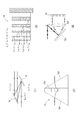
より具体的に説明すると、第二の実施形態では、図12に示すように、パルス圧縮部7としてプリズムペアユニット71が使用されている。この例では、二つのペアのプリズム(合計4個のプリズム)711を備えたユニットとなっている。
図8(1)に示すように、導波路2から出射されるSC光は、1パルスにおいて時刻の早い光ほど長波長であり、時刻の遅い光ほど短波長である。即ち、時刻が進むにつれて光の波長は短波長側にシフトする。このようなチャープパルスは、波長が長くなるにつれて線形的に遅延する群遅延素子によって容易にパルス圧縮できる。図12のプリズムペアユニット71は、このような群遅延を行う素子となっている。二対のプリズム711に対して折り返しミラー712が配設されており、光は、計8回プリズム711中を通過する。
More specifically, in the second embodiment, a
As shown in FIG. 8 (1), the SC light emitted from the
図12に示すように、各プリズム711は三角プリズムであり、図12の紙面に対して垂直方向に長い。二対のプリズム711は、紙面に垂直な面(図12にSで示す)に対して対称である。
図12に示すように、長波長側の光L2は、4個のプリズム711中の合計の光路長が長く、波長が短くなるにつれて合計の光路長は短くなり、最も短波長の光L1で最も短くなる。このため、より波長の長い光ほど遅延が多く生じ、波長が短い光ほど遅延は小さくなる。このため、プリズム711の媒質の屈折率に応じてプリズム711のサイズや配置間隔を適宜選定すると、プリズム711を8回通過して戻ってきた際にSC光における各波長は、時間的に揃った状態で伝搬するようになり、パルスが圧縮される。
As shown in FIG. 12, each
As shown in FIG. 12, the light L 2 of the long wavelength side, long four optical path length of the sum in the
尚、このような優れたパルス圧縮特性は、元の光が線形チャープであることによる。そして、線形チャープは、超短パルスレーザー光の中心波長が、正常分散特性を示すファイバの群速度分散スペクトルのピーク波長にほぼ一致していることによる。超短波レーザー光の中心波長に対して短波長側、長波長側に均一に分散するので、線形チャープパルスが得られる。発明者らの検討によると、線形チャープパルスを容易に得るにようにするには、超短パルスレーザー光の中心波長は、正常分散特性を示すファイバの群速度分散スペクトルのピーク波長に対して±50nmの範囲内であれば良い。 Such an excellent pulse compression characteristic is due to the fact that the original light is a linear chirp. The linear chirp is due to the fact that the center wavelength of the ultrashort pulse laser beam substantially coincides with the peak wavelength of the group velocity dispersion spectrum of the fiber exhibiting normal dispersion characteristics. Since it is uniformly dispersed on the short wavelength side and the long wavelength side with respect to the center wavelength of the ultrashort laser beam, a linear chirp pulse can be obtained. According to the inventors' study, in order to easily obtain a linear chirp pulse, the center wavelength of the ultrashort pulse laser light is ±± the peak wavelength of the group velocity dispersion spectrum of the fiber exhibiting normal dispersion characteristics. It may be within the range of 50 nm.
プリズムペアユニット71のより具体的な設計例を示すと、各プリズム711は石英製(波長1000nmにおいて屈折率=1.45)とされ、頂角は69.1°、プリズム711の間隔(図12にLで示す)は1m、光の入射位置としてd1+d2=10cmとすると、1000nmでの分散値は−822(fs2)程度とされる。スペクトルの中心は1000nm程度であるので、プリズム711の入射面に対する入射角θは、1000nmでのブリュースター角(55.4°)とされる。
When a more specific design example of the
このようにして圧縮されたSC光は、極狭い時間帯に波(光)が重なるようになるため、ピーク強度が高くなる。この様子が、図13に示されている。図13は、第二の実施形態においてピーク強度の増加が確認された実験の結果を示す図である。
図13は、図8に示すSC光を図11に示すような二対のプリズム711で圧縮した実験の結果を示している。図13(1)は、全波長でのパルスを示し、破線は圧縮前のパルス波形(図8(1)と同じ図)、実線は圧縮後のパルスを示す。また、図13(2)はスペクトル分布を示し、破線は圧縮前のもの、実線は圧縮後のものを示す。
尚、図13(1)の角横軸は時間(ピコ秒)であり、各縦軸は強度(kW)である。また、図13(2)の横軸は波長、縦軸は波長で規格化した波長毎のエネルギー(pJ/nm)を示す。
The SC light compressed in this manner has a high peak intensity because waves (light) overlap in an extremely narrow time zone. This is shown in FIG. FIG. 13 is a diagram illustrating a result of an experiment in which an increase in peak intensity was confirmed in the second embodiment.
FIG. 13 shows a result of an experiment in which the SC light shown in FIG. 8 is compressed by two pairs of
In FIG. 13 (1), the horizontal axis represents time (picoseconds), and each vertical axis represents intensity (kW). In FIG. 13B, the horizontal axis indicates the wavelength, and the vertical axis indicates the energy (pJ / nm) for each wavelength normalized by the wavelength.
図13(1)に示すように、プリズムペアユニット71を通すことでSC光はパルス圧縮される。半値幅で見ると、圧縮前は4ピコ秒程度のパルス幅であるが、圧縮後は1ピコ秒程度となる。そして、圧縮によりピーク強度も2倍以上増加している。そして、図13(2)において破線と実線とは殆ど重なっており、圧縮の前後でスペクトル波形に変化は殆どない。即ち、圧縮後も850〜1350nm程度の範囲で連続したスペクトルが得られている。
尚、図13(2)では縦軸は時間積分したエネルギー(pJ)となっており、各波長の光はパルス内で時間積分した量としては変化はないが、パルス幅が短くなっているため、各波長の瞬時値のピークは増加している。増加の仕方は、図13(1)に示す全波長におけるものと同様である。
As shown in FIG. 13 (1), the SC light is pulse-compressed by passing through the
In FIG. 13 (2), the vertical axis represents time-integrated energy (pJ), and the amount of time-integrated light within each pulse does not change, but the pulse width is short. The peak of the instantaneous value of each wavelength is increasing. The manner of increase is the same as that at all wavelengths shown in FIG.
図14は、図13に示すSC光をスペクトルグラムとして示した図である。オリジナルはカラーであるため、図8と同様に下側にパルス波形を示す。
図8と図14とを比較する良くわかるように、パルス圧縮により、各波長の光がほぼ同じ時刻に重なった状態となっている。この重なりの結果、ピーク強度が大幅に増加している。
FIG. 14 is a diagram showing the SC light shown in FIG. 13 as a spectrumgram. Since the original is a color, a pulse waveform is shown on the lower side as in FIG.
As can be seen by comparing FIG. 8 with FIG. 14, the light of each wavelength is overlapped at substantially the same time by pulse compression. As a result of this overlap, the peak intensity is greatly increased.
このように、第二の実施形態のSC光生成光源では、導波路2から出射したSC光を圧縮するパルス圧縮部7を備えているので、ピーク強度が高くなる。このため、多光子励起蛍光顕微鏡等の用途にさらに好適なものとなっている。即ち、ピーク強度が高いために多光子励起が生じ易く、且つパルス幅が狭いために対象物に対するダメージが少なくなる。多光子励起のためには同じ時刻(又は非常に狭い時間帯)に多数の格子が存在していることが必要で、そのためには高いピーク強度が有効である。一方、対象物に対する熱的ダメージは、時間積分した照射量に依存する。したがって、パルス幅が小さくてピーク強度の高い光の方が、生体試料のような熱的に弱い対象物を多光子励起で観察するのに特に好適である。例えば、各種蛍光タンパクについて、褪色を抑制しながら観察を行うことができる。
Thus, since the SC light generation light source of the second embodiment includes the
尚、第二の実施形態のSC光生成光源では、圧縮した光を光路から取り出すための構成が必要である。これには幾つか考えられるが、図12に示す例では、偏向ビームスプリッタ713を用いる構成が採用されている。
即ち、導波路2からの光路上には、偏向ビームスプリッタ713が配置されており、導波路2から出射した偏向ビームスプリッタ713に入射する。偏向ビームスプリッタ713とパルス圧縮部7との間には、1/4波長板714が配置される。上述したように、実施形態のSC光生成光源は偏光制御素子3を備えていて導波路2から出射されるSC光は直線偏光光であるが、導波路2から出射されるSC光が直線偏向光でない場合、導波路2と偏向ビームスプリッタ713との間には、適当な偏光制御素子が配置され、SC光を直線偏光光に変換する。
Note that the SC light generation light source of the second embodiment requires a configuration for extracting compressed light from the optical path. There are several possible ways to do this, but in the example shown in FIG. 12, a configuration using a
That is, a
導波路2からのSC光P1は、偏向ビームスプリッタ713を透過し、1/4波長板714で円偏光P2となった後、各プリズム711で上記の通りパルス圧縮されながら1/4波長板714に戻ってくる。そして、1/4波長板714で当初とは180°異なる向きの直線偏光P3になった後、偏向ビームスプリッタ713に達する。そして、偏向ビームスプリッタ713に反射して光路から取り出されて、目的とする場所に導かれて利用される。
The SC light P1 from the
上記の偏向ビームスプリッタ713でSC光を取り出す構成の他、光路に傾きを設けたり、屋根型ミラーを用いたりする構成が採用されることが多い。これらについて、図15を使用して説明する。図15は、光の取り出しのための他の構成例を示した概略図である。
In addition to the configuration in which the SC beam is extracted by the
図15(1)では、屋根型ミラー716を用いる例が示されている。屋根型ミラー716は、図12の折り返し用ミラー712の代わりに用いられる。屋根型ミラー716を用いる場合、往路と復路は、各プリズム711の長さ方向において互いにずれた経路とされる。この場合も、取り出し用ミラー715を復路の出口に配置し、パルス圧縮されたSC光を取り出す。
In FIG. 15A, an example using a
また、図15(2)は、屋根型ミラーを2個使用することで全体をコンパクト化したパルス圧縮部7の例である。導波路2からのSC光は、プリズム711で屈折した後に第一の屋根型ミラー718に反射して戻り、再度プリズム711を透過する。そして、第二の屋根型ミラー719に反射してさらにプリズム711に戻り、第一の屋根型ミラー718で反射してさらにもう一度プリズム711を透過する。そして、最終的に取り出し用ミラー715に反射して取り出される。この構成では、2個のプルズム(1個のプリズムペア)を使用して光を往復させたのと等価であるが、全体的にコンパクトになっている。
FIG. 15B is an example of the
上記の他、図示は省略するが、図12に示すプリズムペアユニット71において往路と復路とで光路に僅かに傾きを設けるようにしても良い。SC光のビーム径や光路長に応じて傾き角を適宜選定し、パルス圧縮されたSC光がずれた位置に戻ってくるようにし、その位置に取り出し用ミラーを設けて取り出す構成とされる。
In addition to the above, although not shown, in the
尚、図12に示す偏向ビームスプリッタ713を使用する構成では、導波路2からの光が直線偏光光ではない場合、偏光素子を設けて直線偏光光とする必要があり、その際に損失が発生する。図15(1)(2)や傾き角を設ける構成の場合、そのような損失がない点で好適である。
In the configuration using the
次に、パルス圧縮部7の他の例について説明する。第二の実施形態では、パルス圧縮部7としてプリズムペアユニット71が使用されたが、これら以外にも種々の圧縮手段が使用できる。このうち、図16は、パルス圧縮部7の別の例を示す概略図である。
まず、図16(1)に示すように、パルス圧縮部7として、グレーティング(回折格子)72の対を使用することができる。図16(1)において、SC光のパルスのうち、遅い時刻に発生している短波長側の光L1は、早い時刻に発生している長波長側の光L2に比べ、グレーティング72の対を抜け出るまでの光路長が長い。このため、各グレーティング72の配置角度をSC光の中心波長に対して適宜選定することで、各波長がほぼ同じタイミングとなり、パルス圧縮がされる。
Next, another example of the
First, as shown in FIG. 16A, a pair of gratings (diffraction gratings) 72 can be used as the
グレーティング対は、分散の波長幅が大きく取れるので、実施形態のような広帯域のSC光の圧縮用として好適である。但し、効率の問題はある。グレーティング対を用いる場合、SC光の中心波長に応じてブレーズ角を選定するが、ブレーズ角から離れる程回折損失が発生する。つまり、スペクトル強度分布において中心波長から離れる程強度が低くなるような損失が発生する。このため、プリズムペアを用いる場合に比べると、多光子励起可能なピーク強度をもつ波長域が狭くなってしまうことがあり得る。 The grating pair is suitable for compression of broadband SC light as in the embodiment because the wavelength range of dispersion can be increased. However, there are efficiency issues. When a grating pair is used, the blaze angle is selected according to the center wavelength of the SC light, but diffraction loss occurs as the distance from the blaze angle increases. That is, in the spectral intensity distribution, a loss is generated such that the intensity decreases as the distance from the center wavelength increases. For this reason, compared with the case where a prism pair is used, the wavelength region having a peak intensity capable of multiphoton excitation may be narrowed.
また、図16(2)に示すように、パルス圧縮部7としてグリズム73を使用することができる。グリズム73は、2個の面対称配置のプリズム731,731の間に櫛形グレーティング732を配置した構造を有している。一対のプリズム731はプリズムペアと同様に波長に応じた光路長差を生じさせるとともに櫛形グレーティング732による分散(空間的分散)を補償するよう動作する。
グリズムの場合、グレーティング対に比べて小型化できるメリットがある。但し、グレーティングを使用していることに変わりはないので、回折損失の問題はある。
In addition, as shown in FIG. 16 (2), a
In the case of a grism, there is an advantage that it can be made smaller than a grating pair. However, since the grating is still used, there is a problem of diffraction loss.
また、図16(3)は、パルス圧縮部7としてチャープミラー74を使用することができる。チャープミラー74は、基板上に形成された多層膜で光を反射させるミラーであり、長波長の光ほど多層膜の深部で反射するため、結果的に光路長が長くなるミラーである。
チャープミラー74は、比較的簡単にパルス圧縮が行えるものの、1個のチャープミラー74で得られる群遅延は一般に−50fs2程度と小さい。このため、この実施形態におけるパルス圧縮部7として用いるには、例えば200回以上反射を繰り返す必要がある。チャープミラー74の反射率は高いものの、このように多数の反射を繰り返す場合には全体として損失が大きくなる欠点がある。
In FIG. 16 (3), a
Although the
また、図16(4)に示すように、パルス圧縮部7として、SLM(空間光変調器)75を使用することができる。SLM75は、液晶ディスプレイと同様、独立して屈折率が制御される多数の画素を配列した素子であり、印加電圧に応じて2次および高次の分散補償が可能である。SLM75をパルス圧縮に用いる場合、透過型と反射型があるが、反射型の場合、例えば図16(4)に示すように、SC光をグレーティング751で分光した後、レンズ752で平行光とし、各画素に入射させる構成などが採用される。SLM75の場合、任意の波長の光を選択的に群遅延させることができること、および高次の分散補償も可能である長所がある。1回反射での群遅延は一般に数十〜200fs2程度となっている。したがって、この実施形態におけるパルス圧縮用として用いる場合、特に選択的に群遅延や高次の分散補償が必要な波長について追加して用いる、即ち最終的な調整用として用いることが好ましい。
Further, as shown in FIG. 16 (4), an SLM (spatial light modulator) 75 can be used as the
また、実施形態のSC光生成光源におけるパルス圧縮部7として、特定の構造、機能を有するファイバが使用される場合もあり得る。以下、この点について図17を参照して説明する。図17は、パルス圧縮部7のさらに別の例を示す概略図である。
パルス圧縮部7としてファイバを使用する場合のごくシンプルな例は、異常分散ファイバを使用する例である。異常分散ファイバの場合、長波長側の光ほど遅延するので、適宜のGVDを有するファイバを適宜の長さで使用してSC光を通すことで、パルス圧縮を行うことができる。
In addition, a fiber having a specific structure and function may be used as the
A very simple example of using a fiber as the
また、図17(1)に示すように、パルス圧縮部7としてチャープドファイバブラッググレーティング(CFBG)76を使用することができる。FBGは、コアの長さ方向に屈折率が変化する部位を周期的に設けて回折格子を構成したファイバであるが、このうち、CFBG76は、チャープミラーの機能をファイバを使って実現されるように反射位置が波長に応じて異なる位置となるようにしたものということができる。CFBG76において、入射した光のうち、短波長側の光はファイバ中の進行方向の手前側で反射して戻り、長波長側になるにつれて奥側で反射して戻る特性を有するファイバである。
In addition, as shown in FIG. 17A, a chirped fiber Bragg grating (CFBG) 76 can be used as the
また、図17(2)に示すように、パルス圧縮部7として分散減少ファイバ77を用い、断熱ソリトン圧縮を行うようにしても良い。分散減少ファイバ77は、光の伝搬方向に向かって徐々に分散が減少する特性のファイバである。分散減少ファイバ77は、例えば、光の伝搬方向に向かってコア径、クラッド径ともに小さくなる構造のファイバである。基本ソリトンとは、ファイバにおける異常分散と自己位相変調とが釣り合った安定状態を指す。分散減少ファイバ77を用いると距離に応じて連続的に基本ソリトン条件を変化させることができるため基本ソリトンのままパルス圧縮が可能となる。このような断熱ソリトン圧縮は高い圧縮率とsech型の優れたパルス品質を有する。
Further, as shown in FIG. 17B, adiabatic soliton compression may be performed using a
また、図17(3)に示すように、パルス圧縮部7としては、櫛形分散配置ファイバ78を使用することもできる。櫛形分散配置ファイバ78は、分散シフトファイバ(DSF)とシングルモードファイバ(SMF)を交互に配置したファイバである。櫛形分散配置ファイバ78では、ファイバの接合箇所が多くなるので接合箇所での損失の問題があり得るが、市販品ファイバで目的とする圧縮特性のものが得易いメリットがある。
In addition, as shown in FIG. 17 (3), a comb-shaped dispersion-arranged
尚、実施形態のSC光生成光源は、導波路2として非線形ファイバを使用しているので、パルス圧縮部7についてもファイバを使用すると、SC光の生成とパルス圧縮とがファイバ系ですべて行えるので、要素間の親和性が高くなり、取り扱いや調整がし易くなるというメリットがある。
但し、ファイバを用いてパルス圧縮を行う場合、高エネルギーのSC光の入射によって望まない非線形効果が生じないように注意する必要がある。せっかく広帯域でフラットなSC光を生成したのに、パルス圧縮の際に再び非線形光学効果が発生してスペクトルの抜けや極端な落ち込み等が生じることがあり得るが、これは避けなければならない。この観点では、プリズムペア、グレーティング、グリズム、チャープミラーといった群遅延素子はビーム径がμmオーダーであるファイバに対し、空間系のためビーム径を自由に大きくすることが可能であるため非線形光学効果を生じにくいため設計し易い。
In addition, since the SC light generation light source of the embodiment uses a nonlinear fiber as the
However, when performing pulse compression using a fiber, care must be taken so that unwanted nonlinear effects do not occur due to incidence of high-energy SC light. Although it is possible to generate a flat SC light with a wide band, a non-linear optical effect may occur again during pulse compression, resulting in a loss of spectrum or an extreme drop. However, this must be avoided. From this point of view, group delay elements such as prism pairs, gratings, grisms, and chirped mirrors can be made to have a nonlinear optical effect because the beam diameter can be freely increased for fibers with a beam diameter on the order of μm because of the spatial system Easy to design because it does not occur easily.
また、ファイバを使用する場合、パルス圧縮によりピーク強度が高まるから、自己集束等によるファイバの損傷にも気をつける必要がある。ファイバの損傷を防ぐには、コア径を大きくした大口径(Large Mode Area:LMA)ファイバまたは中空コアフォトニックバンドギャップファイバ(Hollow Core Photonic Bandgap Fiber:中空コアPBF)を採用することが有効であり、望まない非線形光学効果によるスペクトル形状の乱れを防止する観点でも有効である。
広帯域においてシングルモード伝搬できるLMAのPCF(LMA−PCF)も既に市販されている。本発明の波長帯全域において異常分散を示すLMA−PCFは現在のところ存在していないが、そのようなものが開発されれば使用することができる。中空コアPBFは、コアが空孔となっているため実質的に光非線形性を生じない特徴を有するが、現在主に市販されているものは低分散のものである。但し、十分な分散を有するものが開発されれば、使用が可能である。
Also, when using a fiber, the peak intensity is increased by pulse compression, so it is necessary to pay attention to fiber damage due to self-focusing or the like. In order to prevent damage to the fiber, it is effective to employ a large core area (LMA) fiber with a large core diameter or a hollow core photonic bandgap fiber (Hollow Core Photonic Bandgap Fiber: hollow core PBF). This is also effective from the viewpoint of preventing the spectral shape from being disturbed by an undesirable nonlinear optical effect.
LMA PCF (LMA-PCF) capable of single mode propagation in a wide band is already on the market. The LMA-PCF that exhibits anomalous dispersion over the entire wavelength band of the present invention does not exist at present, but can be used if such a product is developed. The hollow core PBF has a characteristic that substantially no optical non-linearity is generated because the core is a hole, but what is currently marketed mainly has low dispersion. However, if one with sufficient dispersion is developed, it can be used.
1 パルス発振部
2 導波路
3 偏光制御素子
4 SC光生成光源
5 光学系
51 レンズ
52 ダイクロイックミラー
53 スキャニングミラーユニット
531 スキャニングミラー
54 対物レンズ
6 検出器
61 イメージング装置
62 フィルタ
7 パルス圧縮部
71 プリズムペアユニット
711 プリズム
712 折り返しミラー
713 偏光ビームスプリッタ
714 1/4波長板
72 グレーティング
73 グリズム
74 チャープミラー
75 空間光変調器
76 CFBG
77 分散減少ファイバ
78 櫛形配置ファイバ
DESCRIPTION OF
77 Dispersion-reducing
Claims (22)
超短パルス光を発振するパルス光発振部と、
パルス光発振部から発振された超短パルスレーザー光を非線形光学効果によりスーパーコンティニウム光に変換して出射させる導波路と
を備えており、
導波路は、850nm以上1550nm以下の波長域に含まれる少なくとも200nmの波長幅の帯域において連続したスペクトルのスーパーコンティニウム光となるよう超短パルスレーザー光を変換するものであり、
照射面で対象物を多光子励起可能となるようにスーパーコンティニウム光を出射させるものであることを特徴とするスーパーコンティニウム光生成光源。 A supercontinuum light source that generates and emits supercontinuum light,
A pulsed light oscillator that oscillates ultrashort pulsed light;
A waveguide that converts the ultrashort pulse laser light oscillated from the pulsed light oscillation unit into supercontinuum light by a nonlinear optical effect and emits it.
The waveguide converts ultrashort pulse laser light so as to be supercontinuum light having a continuous spectrum in a wavelength band of at least 200 nm included in a wavelength range of 850 nm to 1550 nm,
A supercontinuum light generating light source that emits supercontinuum light so that a multi-photon excitation of an object can be performed on an irradiation surface.
超短パルス光を発振するパルス光発振部と、
パルス光発振部から発振された超短パルスレーザー光を非線形光学効果によりスーパーコンティニウム光に変換して出射させる導波路と
を備えており、
導波路は、850nm以上1550nm以下の波長域に含まれる少なくとも200nmの波長幅の帯域において連続したスペクトルのスーパーコンティニウム光となるよう超短パルスレーザー光を変換するものであり、
導波路から出射されたスーパーコンティニウム光を圧縮して当該スーパーコンティニウム光のピーク強度を増加させるパルス圧縮部を備えたことを特徴とするスーパーコンティニウム光生成源。 A supercontinuum light source that generates and emits supercontinuum light,
A pulsed light oscillator that oscillates ultrashort pulsed light;
A waveguide that converts the ultrashort pulse laser light oscillated from the pulsed light oscillation unit into supercontinuum light by a nonlinear optical effect and emits it.
The waveguide converts ultrashort pulse laser light so as to be supercontinuum light having a continuous spectrum in a wavelength band of at least 200 nm included in a wavelength range of 850 nm to 1550 nm,
A supercontinuum light generation source comprising a pulse compression unit that compresses supercontinuum light emitted from a waveguide to increase the peak intensity of the supercontinuum light.
パルス光発振部により超短パルス光を発振するステップと、
パルス光発振部から発振された超短パルスレーザー光を導波路に入射させ、導波路における非線形光学効果によりスーパーコンティニウム光に変換して出射させるステップと
を備えており、
導波路は、850nm以上1550nm以下の波長域に含まれる少なくとも200nmの波長幅の帯域において連続したスペクトルのスーパーコンティニウム光となるよう超短パルスレーザー光を変換するものであり、
照射面で対象物を多光子励起可能となるようにスーパーコンティニウム光を出射させることを特徴とするスーパーコンティニウム光生成方法。 A supercontinuum light generation method for generating and emitting supercontinuum light,
Oscillating ultrashort pulsed light by the pulsed light oscillation unit;
A step of causing the ultra-short pulse laser light oscillated from the pulsed light oscillation unit to enter the waveguide, converting it to supercontinuum light by a nonlinear optical effect in the waveguide, and emitting the step.
The waveguide converts ultrashort pulse laser light so as to be supercontinuum light having a continuous spectrum in a wavelength band of at least 200 nm included in a wavelength range of 850 nm to 1550 nm,
A supercontinuum light generation method, characterized in that supercontinuum light is emitted so as to enable multiphoton excitation of an object on an irradiation surface.
パルス光発振部により超短パルス光を発振するステップと、
パルス光発振部から発振された超短パルスレーザー光を導波路に入射させ、導波路における非線形光学効果によりスーパーコンティニウム光に変換して出射させるステップと
を備えており、
導波路は、850nm以上1550nm以下の波長域に含まれる少なくとも200nmの波長幅の帯域において連続したスペクトルのスーパーコンティニウム光となるよう超短パルスレーザー光を変換するものであり、
導波路から出射されたスーパーコンティニウム光を圧縮して当該スーパーコンティニウム光のピーク強度を増加させることを特徴とするスーパーコンティニウム光生成方法。 A supercontinuum light generation method for generating and emitting supercontinuum light,
Oscillating ultrashort pulsed light by the pulsed light oscillation unit;
A step of causing the ultra-short pulse laser light oscillated from the pulsed light oscillation unit to enter the waveguide, converting it to supercontinuum light by a nonlinear optical effect in the waveguide, and emitting the step.
The waveguide converts ultrashort pulse laser light so as to be supercontinuum light having a continuous spectrum in a wavelength band of at least 200 nm included in a wavelength range of 850 nm to 1550 nm,
A method of generating supercontinuum light, comprising compressing supercontinuum light emitted from a waveguide to increase the peak intensity of the supercontinuum light.
前記導波路から出射されたスーパーコンティニウム光を対象物上に照射するための光学系と、
前記対象物を当該スーパーコンティニウム光で多光子励起したときに放出される蛍光を検出する検出部とを備えていることを特徴とする多光子励起蛍光顕微鏡。 A multiphoton excitation fluorescence microscope comprising the supercontinuum light generation light source according to any one of claims 1 to 10,
An optical system for irradiating the object with supercontinuum light emitted from the waveguide;
A multi-photon excitation fluorescence microscope comprising: a detection unit that detects fluorescence emitted when the object is multi-photon excited with the supercontinuum light.
パルス光発振部により超短パルス光を発振する発振ステップと、
パルス光発振部から発振された超短パルスレーザー光を導波路に入射させ、導波路における非線形光学効果によりスーパーコンティニウム光に変換して出射させる変換ステップと、
出射したスーパーコンティニウム光をパルス圧縮してピーク強度を増加させる圧縮ステップと、
圧縮ステップによりピーク強度を増加させたスーパーコンティニウム光の全部又は一部を蛍光物質に照射して蛍光物質を多光子励起する照射ステップと
を備えており、
変換ステップは、850nm以上1550nm以下の波長域に含まれる少なくとも200nmの波長幅の帯域において連続したスペクトルのスーパーコンティニウム光となるよう導波路により超短パルスレーザー光を変換するステップであることを特徴とする多光子励起方法。 A multi-photon excitation method for generating fluorescence by multi-photon excitation of a fluorescent substance with generated supercontinuum light,
An oscillation step of oscillating ultrashort pulsed light by the pulsed light oscillation unit;
A conversion step of causing the ultrashort pulse laser light oscillated from the pulsed light oscillation unit to be incident on the waveguide, converting it into supercontinuum light by a nonlinear optical effect in the waveguide, and
A compression step for increasing the peak intensity by pulse compression of the emitted supercontinuum light; and
An irradiation step of irradiating the fluorescent material with all or part of the supercontinuum light whose peak intensity is increased by the compression step and exciting the fluorescent material with multiphotons,
The conversion step is a step of converting the ultrashort pulse laser light by the waveguide so as to become supercontinuum light having a continuous spectrum in a wavelength band of at least 200 nm included in a wavelength range of 850 nm to 1550 nm. Multi-photon excitation method.
Priority Applications (4)
| Application Number | Priority Date | Filing Date | Title |
|---|---|---|---|
| PCT/JP2017/014049 WO2017175747A1 (en) | 2016-04-05 | 2017-04-04 | Supercontinuum-light-generating light source, supercontinuum-light generation method, multiphoton-excited fluorescence microscope, and multiphoton excitation method |
| DE112017001881.1T DE112017001881T5 (en) | 2016-04-05 | 2017-04-04 | Supercontinuum source, method for generating and emitting a supercontinuum, multiphoton excitation fluorescence microscope and multiphoton excitation method |
| US16/091,819 US11079656B2 (en) | 2016-04-05 | 2017-04-04 | Supercontinuum source, method for generating and emitting a supercontinuum, multiphoton excitation fluorescence microscope, and multiphoton excitation method |
| US17/192,879 US20210191229A1 (en) | 2016-04-05 | 2021-03-04 | Supercontinuum source, method for generating and emitting a supercontinuum, multiphoton excitation fluorescence microscope, and multiphoton excitation method |
Applications Claiming Priority (2)
| Application Number | Priority Date | Filing Date | Title |
|---|---|---|---|
| JP2016076155 | 2016-04-05 | ||
| JP2016076155 | 2016-04-05 |
Publications (3)
| Publication Number | Publication Date |
|---|---|
| JP2017187465A true JP2017187465A (en) | 2017-10-12 |
| JP2017187465A5 JP2017187465A5 (en) | 2019-05-23 |
| JP6729878B2 JP6729878B2 (en) | 2020-07-29 |
Family
ID=60046341
Family Applications (1)
| Application Number | Title | Priority Date | Filing Date |
|---|---|---|---|
| JP2016178605A Active JP6729878B2 (en) | 2016-04-05 | 2016-09-13 | Supercontinuum light generation light source for multiphoton excitation, supercontinuum light generation method for multiphoton excitation, multiphoton excitation fluorescence microscope, and multiphoton excitation method |
Country Status (3)
| Country | Link |
|---|---|
| US (2) | US11079656B2 (en) |
| JP (1) | JP6729878B2 (en) |
| DE (1) | DE112017001881T5 (en) |
Cited By (1)
| Publication number | Priority date | Publication date | Assignee | Title |
|---|---|---|---|---|
| CN112752967A (en) * | 2018-10-12 | 2021-05-04 | 优志旺电机株式会社 | Light source for spectroscopic analysis, spectroscopic analysis device, and spectroscopic analysis method |
Families Citing this family (7)
| Publication number | Priority date | Publication date | Assignee | Title |
|---|---|---|---|---|
| GB2563435A (en) * | 2017-06-16 | 2018-12-19 | The Univ Court Of The Univ Of St Andrews | Three-photon light sheet imaging |
| EP3830913A4 (en) * | 2018-09-05 | 2022-05-25 | IPG Photonics Corporation | Pulse configurable fiber laser unit |
| JP7265908B2 (en) * | 2019-03-27 | 2023-04-27 | ウシオ電機株式会社 | Tablet inspection method and tablet inspection device |
| WO2021024890A1 (en) * | 2019-08-02 | 2021-02-11 | ウシオ電機株式会社 | Broadband pulsed light source device, spectrometry device, spectrometry method, and spectroscopic analysis method |
| DE102020205851B4 (en) * | 2020-05-08 | 2022-01-05 | Carl Zeiss Vision International Gmbh | Device, method and computer program for generating two point light sources of the same wavelength on a pupil plane of an eye and for determining a neuronal transfer function of a visual pathway |
| CN113156735B (en) * | 2020-12-15 | 2022-08-16 | 北京邮电大学 | Inverse ridge type AlGaAs waveguide and method thereof |
| EP4332662A1 (en) * | 2021-04-30 | 2024-03-06 | MGI Tech Co., Ltd. | Field-of-view stitching system and method, and biological sample identification device and method |
Citations (3)
| Publication number | Priority date | Publication date | Assignee | Title |
|---|---|---|---|---|
| US20030156605A1 (en) * | 2002-02-18 | 2003-08-21 | Richardson David J. | Pulsed light sources |
| JP2008216716A (en) * | 2007-03-06 | 2008-09-18 | Univ Nagoya | Supercontinuum light source |
| US20120049092A1 (en) * | 2010-08-26 | 2012-03-01 | The Board Of Trustees Of The University Of Illinois | Compression of Polarized Supercontinuum Pulses Generated in Birefringent All Normal-Dispersion Photonic Crystal Fiber |
Family Cites Families (12)
| Publication number | Priority date | Publication date | Assignee | Title |
|---|---|---|---|---|
| JP3558499B2 (en) | 1996-07-24 | 2004-08-25 | 住友電気工業株式会社 | Optical fiber, light source device and system |
| JP3474773B2 (en) | 1997-06-18 | 2003-12-08 | 日本電信電話株式会社 | White pulse light source |
| JP2003149695A (en) | 2001-11-08 | 2003-05-21 | Nippon Telegr & Teleph Corp <Ntt> | Supercontinium light source |
| US20070216993A1 (en) * | 2004-03-05 | 2007-09-20 | The Furukawa Electric Co., Ltd | Optical Fiber Laser Using Rare Earth-Added Fiber And Wide Band Light Source |
| WO2006133509A1 (en) * | 2005-06-16 | 2006-12-21 | Swinburne University Of Technology | Imaging system |
| EP1995632B1 (en) | 2006-03-15 | 2013-06-12 | Sumitomo Electric Industries, Ltd. | Optical fiber and broadband light source |
| WO2010115432A1 (en) * | 2009-04-08 | 2010-10-14 | Nkt Photonics A/S | Broadband high power light source |
| WO2012135073A2 (en) * | 2011-03-25 | 2012-10-04 | Board Of Trustees Of Michigan State University | Adaptive laser system for ophthalmic use |
| FR2986668B1 (en) | 2012-02-02 | 2014-02-21 | Ecole Polytech | MULTI-COLOR EXCITATION MODULE FOR A MULTI-PHOTONIC IMAGING SYSTEM, SYSTEM AND METHOD THEREOF |
| EP2662939B1 (en) * | 2012-05-08 | 2020-08-19 | Fianium Limited | Laser systems having tapered elements |
| GB2528023A (en) * | 2014-03-18 | 2016-01-13 | Stfc Science & Technology | High power laser with chirped pulse amplification |
| EP3145036B1 (en) * | 2015-09-17 | 2020-03-18 | Academia Sinica | Supercontinuum generation apparatus and method |
-
2016
- 2016-09-13 JP JP2016178605A patent/JP6729878B2/en active Active
-
2017
- 2017-04-04 DE DE112017001881.1T patent/DE112017001881T5/en active Granted
- 2017-04-04 US US16/091,819 patent/US11079656B2/en active Active
-
2021
- 2021-03-04 US US17/192,879 patent/US20210191229A1/en not_active Abandoned
Patent Citations (3)
| Publication number | Priority date | Publication date | Assignee | Title |
|---|---|---|---|---|
| US20030156605A1 (en) * | 2002-02-18 | 2003-08-21 | Richardson David J. | Pulsed light sources |
| JP2008216716A (en) * | 2007-03-06 | 2008-09-18 | Univ Nagoya | Supercontinuum light source |
| US20120049092A1 (en) * | 2010-08-26 | 2012-03-01 | The Board Of Trustees Of The University Of Illinois | Compression of Polarized Supercontinuum Pulses Generated in Birefringent All Normal-Dispersion Photonic Crystal Fiber |
Non-Patent Citations (2)
| Title |
|---|
| GAO ET AL.: "Ultraviolet-enhanced supercontinuumgeneration in uniform photonic crystal fiberpumped by a giant-chi", OPTICS EXPRESS, vol. 22, no. 20, JPN6020019092, 1 October 2014 (2014-10-01), US, pages 24697 - 24705, ISSN: 0004281111 * |
| RESHAK, ALI HUSSAIN: "Second Harmonic Generation Signal from Deep Shade Moisture Plants USING the Two-Photon Laser Scannin", 11TH INTERNATIONAL CONFERENCE ON TRANSPARENT OPTICAL NETWORKS, vol. Tu.A1.4, JPN6017023345, 28 June 2009 (2009-06-28), US, pages 1 - 4, XP031498725, ISSN: 0004220431 * |
Cited By (3)
| Publication number | Priority date | Publication date | Assignee | Title |
|---|---|---|---|---|
| CN112752967A (en) * | 2018-10-12 | 2021-05-04 | 优志旺电机株式会社 | Light source for spectroscopic analysis, spectroscopic analysis device, and spectroscopic analysis method |
| EP3865850A4 (en) * | 2018-10-12 | 2021-11-24 | Ushio Denki Kabushiki Kaisha | Light source for spectroscopic analysis, spectroscopic analysis device, and spectroscopic analysis method |
| US11385173B2 (en) | 2018-10-12 | 2022-07-12 | Ushio Denki Kabushiki Kaisha | Light source for spectroscopic analysis, spectroscopic analysis device, and spectroscopic analysis method |
Also Published As
| Publication number | Publication date |
|---|---|
| JP6729878B2 (en) | 2020-07-29 |
| US20190129278A1 (en) | 2019-05-02 |
| US20210191229A1 (en) | 2021-06-24 |
| US11079656B2 (en) | 2021-08-03 |
| DE112017001881T5 (en) | 2018-12-13 |
Similar Documents
| Publication | Publication Date | Title |
|---|---|---|
| JP6729878B2 (en) | Supercontinuum light generation light source for multiphoton excitation, supercontinuum light generation method for multiphoton excitation, multiphoton excitation fluorescence microscope, and multiphoton excitation method | |
| CN113161851B (en) | Spatially chirped chamber for temporally stretching/compressing optical pulses | |
| US9160137B1 (en) | Method and device for creating supercontinuum light pulses | |
| US8675699B2 (en) | Laser pulse synthesis system | |
| US8064053B2 (en) | 3-color multiplex CARS spectrometer | |
| US20120287428A1 (en) | Nonlinear raman spectroscopic apparatus, microspectroscopic apparatus, and microspectroscopic imaging apparatus | |
| JP5203063B2 (en) | Multiphoton excitation measurement system | |
| JP5931888B2 (en) | Laser light emitting device and spectroscopic analysis method of sample | |
| WO2011089441A1 (en) | Optical sources | |
| US11085824B2 (en) | Coherent anti-Stokes Raman scattering imaging method, and light source for the same | |
| US20200259305A1 (en) | Method and system for generating tunable ultrafast optical pulses | |
| JP6613552B2 (en) | Super-resolution observation apparatus and super-resolution observation method | |
| JP2017187465A5 (en) | ||
| JP2008225454A (en) | Laser microscope | |
| Wise | Femtosecond fiber lasers based on dissipative processes for nonlinear microscopy | |
| CN114324271A (en) | Microscope system selectively driven by self-phase modulation spectrum, method thereof and microscope | |
| WO2017175747A1 (en) | Supercontinuum-light-generating light source, supercontinuum-light generation method, multiphoton-excited fluorescence microscope, and multiphoton excitation method | |
| Tada et al. | Single-beam coherent anti-Stokes Raman scattering spectroscopy using both pump and soliton Stokes pulses from a photonic crystal fiber | |
| JP2004109368A (en) | Microscope | |
| WO2023243052A1 (en) | Light source | |
| JP7467592B2 (en) | All-fiber widely tunable ultrafast laser source | |
| Yakovlev | Advances in real-time nonlinear Raman microscopy | |
| Roman | Light Source Optimization and Characterization for Multimodal Nonlinear Optical Microscopy | |
| Alfano et al. | UV extended supercontinuum source for time resolved and steady state spectroscopy for biological and chemical molecules | |
| Yavaş | Ultrashort and short pulsed fiber laser development for transparent material processing, imaging and spectroscopy applications |
Legal Events
| Date | Code | Title | Description |
|---|---|---|---|
| AA64 | Notification of invalidation of claim of internal priority (with term) |
Free format text: JAPANESE INTERMEDIATE CODE: A241764 Effective date: 20161011 |
|
| A521 | Request for written amendment filed |
Free format text: JAPANESE INTERMEDIATE CODE: A523 Effective date: 20161013 |
|
| A521 | Request for written amendment filed |
Free format text: JAPANESE INTERMEDIATE CODE: A523 Effective date: 20190409 |
|
| A621 | Written request for application examination |
Free format text: JAPANESE INTERMEDIATE CODE: A621 Effective date: 20190409 |
|
| A131 | Notification of reasons for refusal |
Free format text: JAPANESE INTERMEDIATE CODE: A131 Effective date: 20200303 |
|
| A521 | Request for written amendment filed |
Free format text: JAPANESE INTERMEDIATE CODE: A523 Effective date: 20200507 |
|
| TRDD | Decision of grant or rejection written | ||
| A01 | Written decision to grant a patent or to grant a registration (utility model) |
Free format text: JAPANESE INTERMEDIATE CODE: A01 Effective date: 20200609 |
|
| A61 | First payment of annual fees (during grant procedure) |
Free format text: JAPANESE INTERMEDIATE CODE: A61 Effective date: 20200624 |
|
| R150 | Certificate of patent or registration of utility model |
Ref document number: 6729878 Country of ref document: JP Free format text: JAPANESE INTERMEDIATE CODE: R150 |
|
| R250 | Receipt of annual fees |
Free format text: JAPANESE INTERMEDIATE CODE: R250 |