JP2017182139A - Determination apparatus, determination method, and determination program - Google Patents
Determination apparatus, determination method, and determination program Download PDFInfo
- Publication number
- JP2017182139A JP2017182139A JP2016063539A JP2016063539A JP2017182139A JP 2017182139 A JP2017182139 A JP 2017182139A JP 2016063539 A JP2016063539 A JP 2016063539A JP 2016063539 A JP2016063539 A JP 2016063539A JP 2017182139 A JP2017182139 A JP 2017182139A
- Authority
- JP
- Japan
- Prior art keywords
- frame
- vehicle
- luminance
- area
- image data
- Prior art date
- Legal status (The legal status is an assumption and is not a legal conclusion. Google has not performed a legal analysis and makes no representation as to the accuracy of the status listed.)
- Pending
Links
Images


Abstract
Description
本発明は、死角となる領域における対象物の存在を判定する判定装置、判定方法、および判定プログラムに関する。 The present invention relates to a determination apparatus, a determination method, and a determination program for determining the presence of an object in a blind spot area.
近年、車両の運転者を支援するために様々な運転支援技術が開発されている。例えば、特許文献1には、車両の周辺を撮像した時系列の画像から対象物を抽出し、その対象物に係る領域における時系列の輝度変化量に基づいて、対象物が歩行者以外の人工構造物であるか否かを判定する技術が開示されている。 In recent years, various driving support technologies have been developed to support a driver of a vehicle. For example, in Patent Document 1, an object is extracted from a time-series image obtained by imaging the periphery of a vehicle, and the object is an artificial object other than a pedestrian based on a time-series luminance change amount in a region related to the object. A technique for determining whether or not a structure is present is disclosed.
しかしながら、上述した特許文献1の技術は、画像に映っている対象物を判定するものであり、画像に映っていない対象物が死角となる領域に存在するかを判定することはできない。 However, the technique of Patent Document 1 described above is for determining an object appearing in an image, and it is not possible to determine whether an object not appearing in an image is present in a blind spot area.
本発明の目的は、死角となる領域における移動物の存在を判定することができる判定装置、判定方法、および判定プログラムを提供することである。 The objective of this invention is providing the determination apparatus, the determination method, and determination program which can determine the presence of the moving object in the area | region used as a blind spot.
本発明の一態様に係る判定装置は、車両の周辺の画像データを時系列で取得するセンシングカメラから、前記画像データを受け取る入力部と、前記画像データにおいて第1所定値以上の大きさの静止物が存在するとき、前記静止物により前記車両から死角となるブラインド領域の周辺領域に含まれる画素の、第1フレームと前記第1フレーム以降のフレームである第2フレームの間の輝度変化量が、所定の計算方法により算出された前記周辺領域に含まれる画素の輝度変化量の算出値に対して第2所定値以上大きく、かつ、前記第2フレームから所定時間以内のフレームまでに輝度が周期的に変化しないとき、前記ブラインド領域に移動物が存在すると判定する制御部と、を備える構成を採る。 A determination apparatus according to an aspect of the present invention includes an input unit that receives the image data from a sensing camera that acquires image data around the vehicle in time series, and a stillness having a magnitude greater than or equal to a first predetermined value in the image data. When an object is present, a luminance change amount between a first frame and a second frame that is a frame after the first frame of pixels included in a peripheral area of a blind area that becomes a blind spot from the vehicle due to the stationary object is , The luminance cycle is larger than the second predetermined value with respect to the calculated value of the luminance change amount of the pixels included in the peripheral region calculated by a predetermined calculation method, and from the second frame to a frame within a predetermined time. And a control unit that determines that there is a moving object in the blind area when the change does not occur.
本発明の一態様に係る判定方法は、車両の周辺の画像データを時系列で取得するセンシングカメラから、前記画像データを受け取る工程と、前記画像データにおいて第1所定値以上の大きさの静止物が存在するとき、前記静止物により前記車両から死角となるブラインド領域の周辺領域に含まれる画素の、第1フレームと前記第1フレーム以降のフレームである第2フレームの間の輝度変化量が、所定の計算方法により算出された前記周辺領域に含まれる画素の輝度変化量の算出値に対して第2所定値以上大きく、かつ、前記第2フレームから所定時間以内のフレームまでに輝度が周期的に変化しないとき、前記ブラインド領域に移動物が存在すると判定する工程と、を含むようにした。 The determination method according to an aspect of the present invention includes a step of receiving the image data from a sensing camera that acquires image data around the vehicle in time series, and a stationary object having a size equal to or larger than a first predetermined value in the image data. When there is a brightness change amount between a first frame and a second frame that is a frame after the first frame of pixels included in a peripheral area of a blind area that becomes a blind spot from the vehicle due to the stationary object, The luminance is periodically larger than the calculated value of the luminance change amount of the pixels included in the peripheral area calculated by a predetermined calculation method by a second predetermined value or more and within a predetermined time from the second frame. And a step of determining that there is a moving object in the blind area.
本発明の一態様に係る判定プログラムは、車両の周辺の画像データを時系列で取得するセンシングカメラから、前記画像データを受け取る処理と、前記画像データにおいて第1所定値以上の大きさの静止物が存在するとき、前記静止物により前記車両から死角となるブラインド領域の周辺領域に含まれる画素の、第1フレームと前記第1フレーム以降のフレームである第2フレームの間の輝度変化量が、所定の計算方法により算出された前記周辺領域に含まれる画素の輝度変化量の算出値に対して第2所定値以上大きく、かつ、前記第2フレームから所定時間以内のフレームまでに輝度が周期的に変化しないとき、前記ブラインド領域に移動物が存在すると判定する処理と、をコンピュータに実行させるようにした。 A determination program according to an aspect of the present invention includes a process of receiving the image data from a sensing camera that acquires image data around the vehicle in time series, and a stationary object having a size equal to or greater than a first predetermined value in the image data. When there is a brightness change amount between a first frame and a second frame that is a frame after the first frame of pixels included in a peripheral area of a blind area that becomes a blind spot from the vehicle due to the stationary object, The luminance is periodically larger than the calculated value of the luminance change amount of the pixels included in the peripheral area calculated by a predetermined calculation method by a second predetermined value or more and within a predetermined time from the second frame. When the change does not occur, the computer is caused to execute a process of determining that there is a moving object in the blind area.
本発明によれば、死角となる領域における移動物の存在を判定できる。 According to the present invention, it is possible to determine the presence of a moving object in an area that is a blind spot.
以下、本発明の実施の形態について、図面を参照して詳細に説明する。ただし、実施の形態において、同一機能を有する構成には、同一符号を付し、重複する説明は省略する。 Hereinafter, embodiments of the present invention will be described in detail with reference to the drawings. However, in the embodiment, components having the same function are denoted by the same reference numerals, and redundant description is omitted.
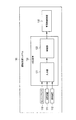
まず、図1を用いて、本実施の形態に係る運転支援システム100および判定装置120の構成について説明する。図1は、本実施の形態に係る運転支援システム100および判定装置120の構成の一例を示すブロック図である。本実施の形態では、運転支援システム100が車両に適用されたものとして説明する。
First, the configuration of the
運転支援システム100は、センシングカメラ110、記憶装置111、検知装置112、判定装置120、および車両制御装置130を備える。また、判定装置120は、入力部121および制御部122を備える。
The
センシングカメラ110は、車室内または車室外に搭載され、車両(運転支援システム100を搭載した自車両)の周辺を撮像する。センシングカメラ110は、所定の時間間隔で車両周辺の撮像を行い、時系列の画像データを取得する。
The
センシングカメラ110は、時系列の画像データを、判定装置120の入力部121へ出力する。
The
記憶装置111は、車室内または車室外に搭載され、例えば3次元の地図情報を記憶する。この地図情報には、例えば、道路に関する道路情報、道路周辺に存在する静止物に関する静止物情報などが含まれる。静止物は、例えば、電柱、街灯、樹木、看板、建物などである。3次元の地図情報は、公知技術であるため、その詳細な説明は省略する。
The
記憶装置111は、地図情報を、判定装置120の入力部121へ出力する。
The
なお、図1では、記憶装置111が運転支援システム100に備えられるように図示したが、記憶装置111は、運転支援システム100の外部(例えば、車両の外部)に備えられてもよい。記憶装置111が車両の外部に備えられる場合、例えば、運転支援システム100は、その記憶装置111に記憶された地図情報を無線通信により受信し、受信した地図情報を入力部121へ出力してもよい。
Although FIG. 1 illustrates that the
検知装置112は、車室内または車室外に搭載され、車両(運転支援システム100を搭載した自車両)の位置を検知する。検知装置112としては、例えば、カメラまたはGPS(Global Positioning System)装置が挙げられる。検知装置112における検知技術は、公知技術であるため、その詳細な説明は省略する。
The
以下、判定装置120について説明する。
Hereinafter, the
入力部121は、センシングカメラ110、記憶装置111、検知装置112から上記各種情報を受け取り、受け取った情報を制御部122へ出力する。
The
制御部122は、入力部121から、時系列の画像データ、地図情報、車両位置情報を受け取る。
The
そして、制御部122は、まず、時系列の画像データに対して画像処理を行い、予め設定された第1所定値以上の大きさの静止物が存在する場合、その静止物の位置と車両の位置に基づいて、ブラインド領域の抽出を行う。
Then, the
ブラインド領域とは、静止物により車両から死角となる領域である。また、第1所定値以上の静止物とは、ブラインド領域が生じうる大きさの静止物であり、例えば建物である。すなわち、画像データ中の静止物がブラインド領域が生じない大きさである場合、ブラインド領域の抽出以降の処理は行われない。 The blind area is an area that becomes a blind spot from the vehicle due to a stationary object. Further, the stationary object having the first predetermined value or more is a stationary object having a size capable of generating a blind region, for example, a building. That is, when the stationary object in the image data has such a size that a blind area does not occur, the processing after the extraction of the blind area is not performed.
ここで、図2を用いて、制御部122によって抽出されるブラインド領域の一例について説明する。図2は、制御部122によって抽出されるブラインド領域の一例を示す図である。また、図2は、車道R1と車道R2との交差点付近を真上から見た状態を示している。
Here, an example of the blind area extracted by the
図2において、車両V1は、車道R1に位置しており、停車中である。矢印d1は、車両V1の進行方向を示している。車両V1には、図1に示した運転支援システム100が搭載されている。
In FIG. 2, the vehicle V1 is located on the roadway R1 and is stopped. An arrow d1 indicates the traveling direction of the vehicle V1. The
また、図2において、車両V2(移動物の一例)は、車道R2に位置しており、走行中である。矢印d2は、車両V2の進行方向を示している。なお、本実施の形態では、移動物の一例が車両(自動車)である場合を例に挙げて説明するが、歩行者または二輪車等であってもよい。 In FIG. 2, a vehicle V2 (an example of a moving object) is located on a road R2, and is traveling. An arrow d2 indicates the traveling direction of the vehicle V2. In the present embodiment, an example in which the moving object is a vehicle (automobile) will be described as an example, but a pedestrian or a two-wheeled vehicle may be used.
また、図2において、車両V1の左斜め前方には、第1所定値以上の大きさである静止物Bが存在している。 In FIG. 2, a stationary object B having a size equal to or larger than the first predetermined value is present obliquely to the left of the vehicle V1.
このような場合、制御部122は、静止物Bの位置と車両V1の位置からブラインド領域Aを抽出する。ブラインド領域Aは、図2に示すように、車両V1から静止物Bを見たときに、静止物Bの後方に広がる領域である。
In such a case, the
図2に示すように、ブラインド領域Aに移動中の車両V2が存在する場合、静止物Bの存在により車両V1から車両V2を視認するのは困難となる。 As shown in FIG. 2, when the moving vehicle V2 exists in the blind area A, it is difficult to visually recognize the vehicle V2 from the vehicle V1 due to the presence of the stationary object B.
以上、制御部122によって抽出されるブラインド領域の一例について説明した。以下、制御部122の説明に戻る。
Heretofore, an example of the blind area extracted by the
上述のようにしてブラインド領域を抽出した後、制御部122は、周辺領域の設定を行う。周辺領域とは、例えば、ブラインド領域に隣接する領域である。
After extracting the blind area as described above, the
ここで、図2を用いて、制御部122によって設定される周辺領域の一例について説明する。
Here, an example of the peripheral area set by the
まず、制御部122は、抽出したブラインド領域Aに隣接する2つの領域a1、a2を周辺領域の候補として抽出する。なお、領域a1、a2の形状、大きさは予め定められている。なお、図2に示すe1、e2はともに、領域a1の端部を示している。
First, the
次に、制御部122は、地図情報に基づいて、2つの領域a1、a2から衝突可能性のある領域のみに限定して選択し、選択した領域を周辺領域に設定する。
Next, the
例えば、制御部122は、領域a1、a2のうち、地図情報から車両V1の進行方向に近い側を周辺領域に設定する。図2の例では、領域a2よりも領域a1の方が車両V1の進行方向に近いため、制御部122は、領域a1を周辺領域に設定する。
For example, the
以上、制御部122によって設定される周辺領域の一例について説明した。以下、制御部122の説明に戻る。
Heretofore, an example of the peripheral area set by the
上述のようにして周辺領域を設定した後、制御部122は、時系列の画像データのそれぞれにおいて、周辺領域に含まれる画素の輝度(以下、周辺領域の輝度という)を算出する。
After setting the peripheral area as described above, the
ここで、図3を用いて、制御部122によって算出される周辺領域の輝度の一例について説明する。なお、以下では、図2に示した領域a1が周辺領域として設定された場合を例に挙げて説明する。
Here, an example of the luminance of the peripheral area calculated by the
また、以下では、時系列の画像データのフレームが、連続する3つのフレーム(以下、第1フレーム、第2フレーム、第3フレームという)である場合を例に挙げて説明する。例えば、第2フレームは、第1フレームの次のフレームであり、第3フレームは、第2フレームの次のフレームであるとする。なお、第1〜第3フレームは、連続するものでなくてもよい。例えば、第2フレームは、第1フレーム以降の所定のフレームであり、第3フレームは、第2フレーム以降の所定のフレームであってもよい。 In the following, a case where the frames of time-series image data are three consecutive frames (hereinafter referred to as a first frame, a second frame, and a third frame) will be described as an example. For example, it is assumed that the second frame is a frame subsequent to the first frame, and the third frame is a frame subsequent to the second frame. The first to third frames may not be continuous. For example, the second frame may be a predetermined frame after the first frame, and the third frame may be a predetermined frame after the second frame.
例えば、第1フレームでは、矢印d2の方向へ走行中の車両V2が領域a1から最も離れた位置(例えば、図2に示した車両V2の位置よりも後方(図2中の左方))に存在しているとする。また、例えば、第2フレームでは、矢印d2の方向へ走行中の車両V2が図2に示した位置に存在しているとする。また、第3フレームでは、矢印d2の方向へ走行中の車両V2が領域a1に最も近い位置(例えば、図2に示した車両V2の位置よりも前方(図2中の右方))に存在しているとする。 For example, in the first frame, the vehicle V2 traveling in the direction of the arrow d2 is farthest from the area a1 (for example, rearward of the position of the vehicle V2 shown in FIG. 2 (leftward in FIG. 2)). Suppose it exists. Further, for example, in the second frame, it is assumed that the vehicle V2 traveling in the direction of the arrow d2 exists at the position shown in FIG. In the third frame, the vehicle V2 traveling in the direction of the arrow d2 is located closest to the area a1 (for example, ahead of the position of the vehicle V2 shown in FIG. 2 (to the right in FIG. 2)). Suppose you are.
制御部122は、第1フレームに含まれる領域a1の端部e1から端部e2までの輝度を算出する。算出された輝度をプロットした例を図3(a)に示す。図3(a)の縦軸は輝度の大きさを示しており、図3(a)の横軸は領域a1の端部e1から端部e2までを示している。
The
上述したとおり、第1フレームでは、車両V2は領域a1から最も離れた位置にあるため、図2に示した車両V2の後方に位置する光源L(例えば、太陽、街灯など)によって生じる車両V2の影は、領域a1にかからない。よって、領域a1の輝度は車両V2の影の影響を受けないため、図3(a)に示すように、輝度の低下部分(例えば、後述の図3(b)に示すp1)は現われない。なお、輝度の低下部分は、特異点ともいう。 As described above, in the first frame, since the vehicle V2 is located farthest from the region a1, the vehicle V2 generated by the light source L (for example, the sun, streetlight, etc.) located behind the vehicle V2 shown in FIG. The shadow does not fall on the area a1. Therefore, since the brightness of the area a1 is not affected by the shadow of the vehicle V2, a reduced brightness portion (for example, p1 shown in FIG. 3B described later) does not appear as shown in FIG. Note that the reduced luminance portion is also called a singular point.
また、制御部122は、第2フレームに含まれる領域a1の端部e1から端部e2までの輝度を算出する。算出された輝度をプロットした例を図3(b)に示す。
Further, the
上述したとおり、第2フレームでは、車両V2は第1フレームにおける位置よりも領域a1に近付いた位置(例えば、図2に示した位置)にあるため、光源Lによって生じる車両V2の影は、領域a1にかかる。よって、図3(b)に示すように、輝度の低下部分p1が現われる。 As described above, in the second frame, since the vehicle V2 is located closer to the region a1 than the position in the first frame (for example, the position shown in FIG. 2), the shadow of the vehicle V2 caused by the light source L is the region. It takes a1. Therefore, as shown in FIG. 3B, a reduced luminance portion p1 appears.
また、制御部122は、第3フレームに含まれる領域a1の端部e1から端部e2までの輝度を算出する。算出された輝度をプロットした例を図3(c)に示す。
Further, the
上述したとおり、第3フレームでは、車両V2は領域a1に最も近い位置にあるため、光源Lによって生じる車両V2の影は、領域a1にかかる。よって、図3(c)に示すように、輝度の低下部分p2が現われる。 As described above, in the third frame, since the vehicle V2 is located closest to the region a1, the shadow of the vehicle V2 caused by the light source L is applied to the region a1. Therefore, as shown in FIG. 3C, a reduced luminance portion p2 appears.
以上、制御部122によって算出される周辺領域の輝度の一例について説明した。以下、制御部122の説明に戻る。
Heretofore, an example of the luminance of the peripheral area calculated by the
上述のようにして周辺領域の輝度をフレーム毎に算出した後、制御部122は、第1フレームと第2フレームの間の輝度変化量(例えば、最大値)が、周辺領域に含まれる画素の輝度変化量の中央値(以下、単に中央値という)に対して、予め設定された第2所定値以上大きいか否かを判定する(第1の判定処理)。
After calculating the luminance of the peripheral region for each frame as described above, the
第1の判定処理について具体的に説明する。第1フレームと第2フレームの間の輝度変化量は、例えば、図3(b)に示した輝度の低下部分p1における変化量の最大値である。また、中央値は、有限個のデータを小さい順に並べたとき中央に位置する値である。例えば、制御部122は、図3(b)に示した輝度の低下部分p1における変化量の最大値が図3(a)に示した中央値に対して第2所定値以上大きいか否かを判定する。なお、ここでは最大値と中央値を採用したが、これらの値は、周辺領域の特異点を抽出できる別の計算方法で求めたもの(例えば、平均値と最大値、最小二乗法近似と最大値など)でもよい。
The first determination process will be specifically described. The amount of change in luminance between the first frame and the second frame is, for example, the maximum value of the amount of change in the reduced luminance portion p1 shown in FIG. The median value is a value located at the center when a finite number of data are arranged in ascending order. For example, the
第1の判定処理の結果、輝度変化量が中央値に対して第2所定値以上大きくない場合、制御部122は、ブラインド領域に移動物が存在しないと判定する。なお、制御部122は、その判定結果を示す情報(以下、判定結果情報という)を車両制御装置130へ出力してもよい。
As a result of the first determination process, when the luminance change amount is not larger than the second predetermined value with respect to the median value, the
一方、第1の判定処理の結果、輝度変化量が中央値に対して第2所定値以上大きい場合、制御部122は、第2フレームから所定時間以内のフレームにおいて輝度が周期的に変化していないかを判定する(第2の判定処理)。
On the other hand, as a result of the first determination process, when the amount of change in luminance is greater than or equal to the second predetermined value with respect to the median value, the
ここで、図5を用いて、輝度の周期的な変化の一例について説明する。 Here, an example of a periodic change in luminance will be described with reference to FIG.
例えば、図5(a)に示すように、周辺領域である領域a1の近傍に樹木Tが存在するとする。この場合、風などの影響を受けて揺れた樹木Tの枝や葉が領域a1にかかることが起こりうる。 For example, as shown in FIG. 5A, it is assumed that a tree T exists in the vicinity of a region a1 that is a peripheral region. In this case, the branches and leaves of the tree T that has been shaken under the influence of wind or the like may be applied to the region a1.
その場合における時系列の輝度の変化を図5(b)〜(d)に示す。図5(b)〜(d)は、それぞれ、連続する第1〜第3フレームにおける領域a1の輝度を示す。 Changes in luminance in time series in that case are shown in FIGS. FIGS. 5B to 5D show the brightness of the area a1 in the first to third frames that are continuous.
樹木Tの枝などが領域a1にかかっていない場合、図5(b)、図5(d)に示す輝度となるが、樹木Tの枝などが領域a1にかかった場合、図5(c)に示す輝度となり、輝度の低下部分p3が現われる。 When the branches of the tree T do not cover the area a1, the luminance is as shown in FIG. 5B and FIG. 5D. However, when the branches of the tree T enter the area a1, FIG. The reduced luminance portion p3 appears.
このように、第1フレームにおいて輝度の低下部分p3が現われておらず、次の第2フレームにおいて輝度の低下部分p3が現われ、次の第3フレームにおいて輝度の低下部分p3が現われないといった場合、輝度の周期的な変化があることになる。 As described above, in the case where the reduced brightness portion p3 does not appear in the first frame, the reduced brightness portion p3 appears in the next second frame, and the reduced brightness portion p3 does not appear in the next third frame. There will be periodic changes in brightness.
このような輝度の周期的な変化をブラインド領域における移動物の移動によるものと捉えてしまうと、ブラインド領域に移動物が存在するとの誤判定につながる。そこで、本実施の形態では、第2の判定処理により、輝度の周期的な変化がある場合を排除することとした。 If such a periodic change in luminance is considered to be due to the movement of a moving object in the blind area, it will lead to an erroneous determination that there is a moving object in the blind area. Therefore, in the present embodiment, the case where there is a periodic change in luminance is excluded by the second determination process.
以上、輝度の周期的な変化の一例について説明した。以下、第2の判定処理について具体的に説明する。 Heretofore, an example of a periodic change in luminance has been described. Hereinafter, the second determination process will be specifically described.
例えば、制御部122は、第2フレームから第3フレーム(所定時間以内のフレームの一例)において輝度が周期的に変化していないかを判定する。
For example, the
例えば、図3(b)に示すように第2フレームにおいて輝度の低下部分p1が現われており、図3(c)に示すように第3フレームにおいても輝度の低下部分p2が現われている場合、制御部122は、輝度の周期的な変化がないと判定する。
For example, when a reduced brightness portion p1 appears in the second frame as shown in FIG. 3B, and a reduced brightness portion p2 appears in the third frame as shown in FIG. The
一方、例えば、図3(b)に示すように第2フレームにおいて輝度の低下部分p1が現われていたが、第3フレームにおいて輝度の低下部分が現われていない場合(例えば、第3フレームの輝度が図3(a)に示す第1フレームの輝度と同じである場合)、制御部122は、輝度の周期的な変化があると判定する。
On the other hand, for example, as shown in FIG. 3B, when the reduced brightness portion p1 appears in the second frame, but the reduced brightness portion does not appear in the third frame (for example, the brightness of the third frame is In the case where the luminance is the same as the luminance of the first frame shown in FIG. 3A), the
第2の判定処理の結果、輝度の周期的な変化がある場合、制御部122は、ブラインド領域に移動物が存在しないと判定する。なお、制御部122は、その判定結果を示す判定結果情報を車両制御装置130へ出力してもよい。
If there is a periodic change in luminance as a result of the second determination process, the
一方、第2の判定処理の結果、輝度の周期的な変化がない場合、制御部122は、ブラインド領域(例えば、図2のブラインド領域A)に移動物(例えば、図2の車両V2)が存在すると判定する。そして、制御部122は、判定結果を示す判定結果情報を車両制御装置130へ出力する。
On the other hand, as a result of the second determination process, when there is no periodic change in luminance, the
なお、第2の判定処理の結果、輝度の周期的な変化がない場合、制御部122は、さらに、第2フレームから所定時間以内のフレームまでの周辺領域内の候補領域の大きさ(図3における横軸方向の幅)が、予め設定された第3所定値以上大きいか否かを判定してもよい(第3の判定処理)。
When there is no periodic change in luminance as a result of the second determination process, the
第3の判定処理について図4を用いて具体的に説明する。第2フレームにおける周辺領域の輝度を図4(a)に示し、第3フレームにおける周辺領域の輝度を図4(b)に示す。また、例えば所定時間以内のフレームが第3フレームである場合の、第2フレームから第3フレームまでの輝度変化量を図4(c)に示す。 The third determination process will be specifically described with reference to FIG. FIG. 4A shows the luminance of the peripheral area in the second frame, and FIG. 4B shows the luminance of the peripheral area in the third frame. For example, FIG. 4C shows the luminance change amount from the second frame to the third frame when the frame within the predetermined time is the third frame.
制御部122は、輝度変化量の最大値と中央値との差分が第4の所定値TH4以上の部分より大きい部分の幅wを候補領域の大きさとして、この候補領域wの大きさが第3の所定値以上大きいか否かを判定する。
The
第3の判定処理の結果、候補領域の大きさが第3所定値以上大きくない場合、制御部122は、ブラインド領域に移動物が存在しないと判定する。なお、制御部122は、その判定結果を示す判定結果情報を車両制御装置130へ出力してもよい。
As a result of the third determination process, when the size of the candidate area is not larger than the third predetermined value, the
一方、第3の判定処理の結果、候補領域の大きさが第3所定値以上大きい場合、制御部122は、ブラインド領域(例えば、図2のブラインド領域A)に移動物(例えば、図2の車両V2)が存在すると判定する。そして、制御部122は、判定結果を示す判定結果情報を車両制御装置130へ出力する。
On the other hand, as a result of the third determination process, when the size of the candidate area is larger than the third predetermined value, the
上述した第3の判定処理を行うことによって、ブラインド領域に移動物が存在するかをより確実に判定することができる。 By performing the third determination process described above, it is possible to more reliably determine whether there is a moving object in the blind area.
以上、判定装置120について説明した。
The
車両制御装置130は、車両において用いられる機器を制御する装置である。車両において用いられる機器としては、例えば、走行機器または表示機器などが挙げられる。
The
ここで、車両制御装置130が走行機器を制御する場合について説明する。
Here, a case where the
例えば、判定結果情報がブラインド領域に移動物が存在しない旨を示す場合、車両制御装置130は、車両の走行を許可する旨の制御信号を走行機器へ出力する。走行機器は、その制御信号に基づいて、走行を許可するように車両を制御する。これにより、例えば図2の場合、車両V1は交差点内へ進入することができる。
For example, when the determination result information indicates that there is no moving object in the blind area, the
一方、例えば、判定結果情報がブラインド領域に移動物が存在する旨を示す場合、車両制御装置130は、車両の走行を禁止する旨の制御信号を走行機器へ出力する。走行機器は、その制御信号に基づいて、走行を禁止するように車両を制御する。これにより、例えば図2の場合、車両は交差点内へ進入することができない。
On the other hand, for example, when the determination result information indicates that there is a moving object in the blind area, the
次に、車両制御装置130が表示機器を制御する場合について説明する。
Next, the case where the
例えば、判定結果情報がブラインド領域に移動物が存在しない旨を示す場合、車両制御装置130は、その旨を表す画像の生成を指示する制御信号を表示機器へ出力する。表示機器は、その制御信号に基づいて、ブラインド領域に移動物が存在しない旨を表す画像を生成し、その画像を所定の表示媒体へ出力する。これにより、例えば図2の場合、車両の乗員は、交差点内へ進入可能であることを知ることができる。
For example, when the determination result information indicates that there is no moving object in the blind area, the
一方、例えば、判定結果情報がブラインド領域に移動物が存在する旨を示す場合、車両制御装置130は、その旨を表す画像の生成を指示する制御信号を表示機器へ出力する。表示機器は、その制御信号に基づいて、ブラインド領域に移動物が存在する旨を表す画像を生成し、その画像を所定の表示媒体へ出力する。これにより、例えば図2の場合、車両の乗員は、交差点内へ進入できないことを知ることができる。
On the other hand, for example, when the determination result information indicates that there is a moving object in the blind area, the
なお、上記表示機器に対する制御の説明では、画像の出力を例に挙げたが、これに限定されず、車両の乗員が判定結果情報の内容を識別可能な手段(例えば、音声の出力、座席の振動等)が用いられてもよい。 In the description of the control for the display device, the output of the image is given as an example. However, the present invention is not limited to this, and means (for example, output of voice, seat) that enables the vehicle occupant to identify the content of the determination result information. Vibration etc.) may be used.
以上、運転支援システム100および判定装置120の構成について説明した。
The configuration of the driving
なお、上述した運転システム100の各装置における動作は、自動運転の実行時またはマニュアル運転(手動運転)の実行時のいずれにおいても有効である。
In addition, the operation | movement in each apparatus of the driving |
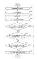
次に、図6を用いて、判定装置120の動作について説明する。図6は、判定装置120における動作の流れを示すフロー図である。本フローは、例えば、判定装置120を搭載した車両の走行停止時に実施される。
Next, the operation of the
まず、入力部121は、センシングカメラ110から時系列の画像データを受け取る(ステップS101)。また、入力部121は、記憶装置111から地図情報(道路情報、静止物情報等を含む)を受け取り、検知装置112から車両位置情報を受け取る。そして、入力部121は、画像データ、地図情報、車両位置情報を制御部122へ出力する。
First, the
次に、制御部122は、入力部121から画像データ、地図情報、車両位置情報を受け取ると、時系列の画像データにおいてブラインド領域の抽出を行う(ステップS102)。この抽出処理は、上述したとおり、画像データにおいて第1所定値以上の大きさの静止物が存在する場合に実行される。また、上述したとおり、ブラインド領域は、静止物の位置および車両の位置に基づいて抽出される。
Next, when receiving the image data, the map information, and the vehicle position information from the
次に、制御部122は、周辺領域の設定を行う(ステップS103)。上述したとおり、周辺領域の設定は、例えば、地図情報に基づいて行われる。
Next, the
次に、制御部122は、時系列の画像データのフレーム毎に周辺領域の輝度を算出する(ステップS104)。
Next, the
次に、制御部122は、第1フレームと第2フレームの間の輝度変化量が中央値に対して第2所定値以上大きいか否かを判定する(ステップS105)。
Next, the
輝度変化量が中央値に対して第2所定値以上大きくない場合(ステップS105:NO)、フローは終了する。なお、ステップS105においてNOの場合、制御部122は、ブラインド領域に移動物が存在しないと判定し、その旨の判定結果情報を車両制御装置130へ出力してもよい。
When the amount of change in luminance is not larger than the second predetermined value with respect to the median value (step S105: NO), the flow ends. If NO in step S105,
輝度変化量が中央値に対して第2所定値以上大きい場合(ステップS105:YES)、制御部122は、第2フレームから所定時間以内のフレームにおいて輝度が周期的に変化していないかを判定する(ステップS106)。
When the amount of change in luminance is greater than or equal to the second predetermined value with respect to the median value (step S105: YES), the
輝度が周期的に変化している場合(ステップS106:YES)、フローは終了する。なお、ステップS106においてYESの場合、制御部122は、ブラインド領域に移動物が存在しないと判定し、その旨の判定結果情報を車両制御装置130へ出力してもよい。
If the luminance changes periodically (step S106: YES), the flow ends. If YES in step S106,
輝度が周期的に変化していない場合(ステップS106:NO)、制御部122は、さらに、第2フレームから所定時間以内のフレームまでの周辺領域内の候補領域の大きさ(例えば、図3における横軸方向の幅)が、予め設定された第3所定値以上大きいか否かを判定する(ステップS107)。
When the luminance does not change periodically (step S106: NO), the
候補領域の大きさが第3所定値以上大きくない場合(ステップS107:NO)、フローは終了する。なお、ステップS107においてNOの場合、制御部122は、ブラインド領域に移動物が存在しないと判定し、その旨の判定結果情報を車両制御装置130へ出力してもよい。
If the size of the candidate area is not larger than the third predetermined value (step S107: NO), the flow ends. If NO in step S107,
候補領域の大きさが第3所定値以上大きい場合(ステップS107:YES)、制御部122は、ブラインド領域に移動物が存在すると判定する(ステップS108)。そして、制御部122は、ブラインド領域に移動物が存在する旨の判定結果情報を車両制御装置130へ出力する。
When the size of the candidate area is larger than the third predetermined value (step S107: YES), the
以上、判定装置120の動作例について説明した。
The operation example of the
本発明の実施の形態によれば、時系列の画像データにおけるブラインド領域の周辺領域の輝度変化量に基づいて、ブラインド領域に移動物が存在するか否かを判定することができる。よって、例えばマニュアル運転の場合、上記判定により、車両の乗員がブラインド領域に移動物が存在することを認識できるので、安全運転の向上に寄与することができる。また、例えば自動運転の場合、ブラインド領域における移動物の有無が判らないことによって停車中の車両が交差点に進入できないという課題を解決できる。 According to the embodiment of the present invention, it is possible to determine whether or not there is a moving object in the blind area based on the luminance change amount of the peripheral area of the blind area in the time-series image data. Therefore, for example, in the case of manual driving, the above determination allows the vehicle occupant to recognize that there is a moving object in the blind area, which can contribute to improvement of safe driving. Further, for example, in the case of automatic driving, it is possible to solve the problem that the stopped vehicle cannot enter the intersection by not knowing whether there is a moving object in the blind area.
なお、本発明は上記実施の形態に限定されるものではなく、種々の変形が可能である。以下、各変形例について説明する。 In addition, this invention is not limited to the said embodiment, A various deformation | transformation is possible. Hereinafter, each modification will be described.
(変形例1)
実施の形態では、周辺領域に設定された領域a1において、車両V2の影による輝度の低下が生じる場合を例に挙げて説明したが、これに限定されない。例えば、車両V2のヘッドライトの点灯による輝度の増加であってもよい。この例について図7を用いて以下に説明する。
(Modification 1)
In the embodiment, the case where the brightness is reduced due to the shadow of the vehicle V2 in the area a1 set as the peripheral area has been described as an example. However, the present invention is not limited to this. For example, the luminance may be increased by turning on the headlight of the vehicle V2. This example will be described below with reference to FIG.
図7(a)〜(c)は、それぞれ、連続する第1〜第3フレームにおける領域a1の輝度を示す。第1〜第3フレームにおける車両V2の位置は、上述した実施の形態と同様である。 FIGS. 7A to 7C show the luminance of the area a1 in the first to third frames that are continuous. The position of the vehicle V2 in the first to third frames is the same as in the above-described embodiment.
第1フレームでは、車両V2は領域a1から最も離れた位置にあるため、車両V2のヘッドライトの光は、領域a1にかからない。よって、領域a1の輝度は車両V2のヘッドライトの光の影響を受けないため、図7(a)に示すように、輝度の増加部分(例えば、後述の図7(b)に示すp4)は現われない。なお、輝度の増加部分は、特異点ともいう。 In the first frame, since the vehicle V2 is located farthest from the region a1, the light from the headlight of the vehicle V2 does not reach the region a1. Therefore, since the brightness of the area a1 is not affected by the light of the headlight of the vehicle V2, as shown in FIG. 7A, the increased portion of brightness (for example, p4 shown in FIG. 7B described later) is Does not appear. Note that the increased luminance portion is also referred to as a singular point.
第2フレームでは、車両V2は第1フレームにおける位置よりも領域a1に近付いた位置(例えば、図2に示した位置)にあるため、車両V2のヘッドライトの光は、領域a1にかかる。よって、図7(b)に示すように、輝度の増加部分p4が現われる。 In the second frame, since the vehicle V2 is located closer to the region a1 than the position in the first frame (for example, the position shown in FIG. 2), the light of the headlight of the vehicle V2 is applied to the region a1. Therefore, as shown in FIG. 7B, an increased luminance portion p4 appears.
第3フレームでは、車両V2は領域a1に最も近い位置にあるため、車両V2のヘッドライトの光は、領域a1にかかる。よって、図7(c)に示すように、輝度の増加部分p5が現われる。p5は、p4に比べて、輝度の増加量が多い。 In the third frame, since the vehicle V2 is closest to the region a1, the light of the headlight of the vehicle V2 is applied to the region a1. Therefore, as shown in FIG. 7C, a luminance increasing portion p5 appears. p5 has a larger amount of increase in luminance than p4.
(変形例2)
実施の形態では、地図情報に基づいて周辺領域を設定する場合を例に挙げて説明したが、これに限定されない。例えば、図2に示した光源L(例えば、太陽、街灯など)の位置に基づいて周辺領域を設定してもよい。この例について、図8、図9を用いて以下に説明する。なお、以下では、光源Lが太陽である場合を例に挙げて説明する。
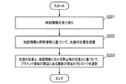
(Modification 2)
In the embodiment, the case where the peripheral area is set based on the map information has been described as an example. However, the present invention is not limited to this. For example, the peripheral region may be set based on the position of the light source L (for example, the sun, street lamp, etc.) shown in FIG. This example will be described below with reference to FIGS. Hereinafter, a case where the light source L is the sun will be described as an example.
まず、入力部121は、検知装置112から現在時刻を示す時刻情報を受け取る(ステップS201)。そして、入力部121は、その時刻情報を制御部122へ出力する。
First, the
なお、上述したとおり、現在時刻は、制御部122が検知してもよい。その場合、ステップS201の処理は省略される。
As described above, the
次に、制御部122は、地図情報と時刻情報に基づいて、光源Lの位置を認識する(ステップS202)。地図情報と時刻情報に基づく光源Lの位置を認識する技術は、公知技術であるため、その詳細な説明は省略する。なお、光源が街灯である場合は、制御部122は、地図情報のみに基づいて光源Lの位置を認識する。その場合、ステップS201の処理は省略される。
Next, the
次に、制御部122は、光源Lの位置と、地図情報(静止物情報)に示される静止物Bの位置とに基づいて、ブラインド領域Aの周辺にある複数の領域a1、a2のうちの1つを選択する(ステップS203)。
Next, based on the position of the light source L and the position of the stationary object B indicated in the map information (stationary object information), the
ここで、図9を用いて、ステップS203の処理の例について説明する。 Here, an example of the process of step S203 will be described with reference to FIG.
例えば、図9(a)に示すように、光源Lがブラインド領域Aよりも左側にあると認識した場合、ブラインド領域Aに存在しうる移動物(例えば、図2の車両V2)の影は領域a1に向けてのびるため、制御部122は、領域a1を選択し、周辺領域に設定する。
For example, as shown in FIG. 9A, when the light source L is recognized as being on the left side of the blind area A, the shadow of the moving object (for example, the vehicle V2 in FIG. 2) that can exist in the blind area A is the area. In order to extend toward a1, the
また、例えば、図9(b)に示すように、光源Lがブラインド領域Aよりも右側にあると認識した場合、ブラインド領域Aに存在しうる移動物(例えば、図2の車両V2)の影は領域a2に向けてのびるため、制御部122は、領域a2を選択し、周辺領域に設定する。
Further, for example, as shown in FIG. 9B, when the light source L is recognized as being on the right side of the blind area A, the shadow of the moving object (for example, the vehicle V2 in FIG. 2) that may exist in the blind area A Since it extends toward the area a2, the
以上、本発明の各変形例について説明した。なお、各変形例は、任意に組み合わせてもよい。 In the above, each modification of this invention was demonstrated. In addition, you may combine each modification arbitrarily.
実施の形態および各変形例における各部の機能は、プログラムにより実現されてもよい。その場合におけるコンピュータのハードウェア構成例を図10に示す。 The function of each part in the embodiment and each modification may be realized by a program. An example of the hardware configuration of the computer in that case is shown in FIG.
図10に示すように、コンピュータ2100は、入力ボタン、タッチパッドなどの入力装置2101、ディスプレイ、スピーカなどの出力装置2102、CPU(Central Processing Unit)2103、ROM(Read Only Memory)2104、RAM(Random Access Memory)2105を備える。また、コンピュータ2100は、ハードディスク装置、SSD(Solid State Drive)などの記憶装置2106、DVD−ROM(Digital Versatile Disk Read Only Memory)、USB(Universal Serial Bus)メモリなどの記録媒体から情報を読み取る読取装置2107、ネットワークを介して通信を行う送受信装置2108を備える。上述した各部は、バス2109により接続される。
As shown in FIG. 10, the
そして、読取装置2107は、上記各部の機能を実現するためのプログラムを記録した記録媒体からそのプログラムを読み取り、記憶装置2106に記憶させる。あるいは、送受信装置2108が、ネットワークに接続されたサーバ装置と通信を行い、サーバ装置からダウンロードした上記各部の機能を実現するためのプログラムを記憶装置2106に記憶させる。
Then, the
そして、CPU2103が、記憶装置2106に記憶されたプログラムをRAM2105にコピーし、そのプログラムに含まれる命令をRAM2105から順次読み出して実行することにより、上記各部の機能が実現される。また、プログラムを実行する際、RAM2105または記憶装置2106には、実施の形態および各変形例で述べた各種処理で得られた情報が記憶され、適宜利用される。
Then, the
本発明にかかる判定装置、判定方法、および判定プログラムは、死角となる領域における対象物の存在を判定する技術全般に有用である。 The determination apparatus, determination method, and determination program according to the present invention are useful for all techniques for determining the presence of an object in a blind spot area.
100 運転支援システム
110 センシングカメラ
111 記憶装置
112 検知装置
120 判定装置
121 入力部
122 制御部
130 車両制御装置
2100 コンピュータ
2101 入力装置
2102 出力装置
2103 CPU
2104 ROM
2105 RAM
2106 記憶装置
2107 読取装置
2108 送受信装置
2109 バス
DESCRIPTION OF
2104 ROM
2105 RAM
2106
Claims (7)
前記画像データにおいて第1所定値以上の大きさの静止物が存在するとき、前記静止物により前記車両から死角となるブラインド領域の周辺領域に含まれる画素の、第1フレームと前記第1フレーム以降のフレームである第2フレームの間の輝度変化量が、所定の計算方法により算出された前記周辺領域に含まれる画素の輝度変化量の算出値に対して第2所定値以上大きく、かつ、前記第2フレームから所定時間以内のフレームまでに輝度が周期的に変化しないとき、前記ブラインド領域に移動物が存在すると判定する制御部と、
を備える判定装置。 An input unit that receives the image data from a sensing camera that acquires image data around the vehicle in time series;
When there is a stationary object having a size equal to or larger than a first predetermined value in the image data, the first frame and the first and subsequent frames of pixels included in a peripheral area of a blind area that becomes a blind spot from the vehicle by the stationary object The amount of change in brightness between the second frames, which is the second frame, is greater than or equal to a second predetermined value with respect to the calculated value of the amount of change in luminance of the pixels included in the peripheral region calculated by a predetermined calculation method, and A controller that determines that there is a moving object in the blind area when the luminance does not change periodically from the second frame to a frame within a predetermined time;
A determination apparatus comprising:
請求項1に記載の判定装置。 The control unit further determines that there is a moving object in the blind area when the size of the candidate area from the second frame to a frame within a predetermined time is greater than a preset third predetermined value,
The determination apparatus according to claim 1.
前記制御部は、前記地図情報に基づいて、前記周辺領域を設定する、
請求項1または2に記載の判定装置。 The input unit further receives map information,
The control unit sets the peripheral area based on the map information.
The determination apparatus according to claim 1 or 2.
前記制御部は、前記地図情報と前記時刻情報に基づいて所定の光源の位置を認識し、前記光源の位置と、前記地図情報における前記静止物の位置とに基づいて、前記周辺領域を設定する、
請求項3に記載の判定装置。 The input unit further receives time information,
The control unit recognizes a position of a predetermined light source based on the map information and the time information, and sets the peripheral area based on the position of the light source and the position of the stationary object in the map information. ,
The determination apparatus according to claim 3.
請求項1から4のいずれか1項に記載の判定装置。 The calculated value is a median value of luminance change amounts of pixels included in the peripheral region.
The determination apparatus according to any one of claims 1 to 4.
前記画像データにおいて第1所定値以上の大きさの静止物が存在するとき、前記静止物により前記車両から死角となるブラインド領域の周辺領域に含まれる画素の、第1フレームと前記第1フレーム以降のフレームである第2フレームの間の輝度変化量が、所定の計算方法により算出された前記周辺領域に含まれる画素の輝度変化量の算出値に対して第2所定値以上大きく、かつ、前記第2フレームから所定時間以内のフレームまでに輝度が周期的に変化しないとき、前記ブラインド領域に移動物が存在すると判定する工程と、
を含む判定方法。 Receiving the image data from a sensing camera that obtains image data around the vehicle in time series; and
When there is a stationary object having a size equal to or larger than a first predetermined value in the image data, the first frame and the first and subsequent frames of pixels included in a peripheral area of a blind area that becomes a blind spot from the vehicle by the stationary object The amount of change in brightness between the second frames, which is the second frame, is greater than or equal to a second predetermined value with respect to the calculated value of the amount of change in luminance of the pixels included in the peripheral region calculated by a predetermined calculation method, and Determining that there is a moving object in the blind area when the luminance does not change periodically from the second frame to a frame within a predetermined time; and
A determination method including
前記画像データにおいて第1所定値以上の大きさの静止物が存在するとき、前記静止物により前記車両から死角となるブラインド領域の周辺領域に含まれる画素の、第1フレームと前記第1フレーム以降のフレームである第2フレームの間の輝度変化量が、所定の計算方法により算出された前記周辺領域に含まれる画素の輝度変化量の算出値に対して第2所定値以上大きく、かつ、前記第2フレームから所定時間以内のフレームまでに輝度が周期的に変化しないとき、前記ブラインド領域に移動物が存在すると判定する処理と、
をコンピュータに実行させる判定プログラム。 A process of receiving the image data from a sensing camera that acquires image data around the vehicle in time series,
When there is a stationary object having a size equal to or larger than a first predetermined value in the image data, the first frame and the first and subsequent frames of pixels included in a peripheral area of a blind area that becomes a blind spot from the vehicle by the stationary object The amount of change in brightness between the second frames, which is the second frame, is greater than or equal to a second predetermined value with respect to the calculated value of the amount of change in luminance of the pixels included in the peripheral region calculated by a predetermined calculation method, and A process for determining that there is a moving object in the blind area when the luminance does not change periodically from the second frame to a frame within a predetermined time; and
A judgment program that causes a computer to execute.
Priority Applications (1)
| Application Number | Priority Date | Filing Date | Title |
|---|---|---|---|
| JP2016063539A JP2017182139A (en) | 2016-03-28 | 2016-03-28 | Determination apparatus, determination method, and determination program |
Applications Claiming Priority (1)
| Application Number | Priority Date | Filing Date | Title |
|---|---|---|---|
| JP2016063539A JP2017182139A (en) | 2016-03-28 | 2016-03-28 | Determination apparatus, determination method, and determination program |
Publications (1)
| Publication Number | Publication Date |
|---|---|
| JP2017182139A true JP2017182139A (en) | 2017-10-05 |
Family
ID=60006117
Family Applications (1)
| Application Number | Title | Priority Date | Filing Date |
|---|---|---|---|
| JP2016063539A Pending JP2017182139A (en) | 2016-03-28 | 2016-03-28 | Determination apparatus, determination method, and determination program |
Country Status (1)
| Country | Link |
|---|---|
| JP (1) | JP2017182139A (en) |
Cited By (3)
| Publication number | Priority date | Publication date | Assignee | Title |
|---|---|---|---|---|
| DE112020001535T5 (en) | 2019-03-25 | 2021-12-09 | Denso Corporation | ROAD SURFACE CONDITION DETERMINATION DEVICE FOR VEHICLES, DRIVER ASSISTANCE SYSTEM AND ROAD SURFACE CONDITION METHOD |
| US11834039B2 (en) | 2019-04-04 | 2023-12-05 | Denso Corporation | Falling object determination device, driving support system, and falling object determination method |
| US11919511B2 (en) | 2019-03-19 | 2024-03-05 | Denso Corporation | Driving support control device for vehicle, driving support system, and driving support method |
-
2016
- 2016-03-28 JP JP2016063539A patent/JP2017182139A/en active Pending
Cited By (4)
| Publication number | Priority date | Publication date | Assignee | Title |
|---|---|---|---|---|
| US11919511B2 (en) | 2019-03-19 | 2024-03-05 | Denso Corporation | Driving support control device for vehicle, driving support system, and driving support method |
| DE112020001535T5 (en) | 2019-03-25 | 2021-12-09 | Denso Corporation | ROAD SURFACE CONDITION DETERMINATION DEVICE FOR VEHICLES, DRIVER ASSISTANCE SYSTEM AND ROAD SURFACE CONDITION METHOD |
| US11970171B2 (en) | 2019-03-25 | 2024-04-30 | Denso Corporation | Road surface condition determination device for vehicle, driving assistance system, and road surface condition determination method |
| US11834039B2 (en) | 2019-04-04 | 2023-12-05 | Denso Corporation | Falling object determination device, driving support system, and falling object determination method |
Similar Documents
| Publication | Publication Date | Title |
|---|---|---|
| JP6313646B2 (en) | External recognition device | |
| JP5127182B2 (en) | Object detection device | |
| JP4697101B2 (en) | Vehicle detection device and light control device | |
| JP6303090B2 (en) | Image processing apparatus and image processing program | |
| JP6453192B2 (en) | Image recognition processing apparatus and program | |
| EP2960829A2 (en) | Lane boundary estimation device and lane boundary estimation method | |
| JP6457278B2 (en) | Object detection apparatus and object detection method | |
| JP5480917B2 (en) | Vehicle periphery monitoring device | |
| JP5065172B2 (en) | Vehicle lighting determination device and program | |
| US10896542B2 (en) | Moving body image generation recording display device and program product | |
| JP5884635B2 (en) | Driving environment detection device, driving environment detection program, and light control device | |
| JP2014006885A (en) | Level difference recognition apparatus, level difference recognition method, and program for level difference recognition | |
| JP2008262333A (en) | Road surface discrimination device and road surface discrimination method | |
| JP2008158640A (en) | Moving object detection apparatus | |
| JPWO2017115732A1 (en) | Image processing apparatus, object recognition apparatus, device control system, image processing method, and image processing program | |
| JP2017182139A (en) | Determination apparatus, determination method, and determination program | |
| JP2014106739A (en) | In-vehicle image processing device | |
| JP6152261B2 (en) | Car parking frame recognition device | |
| JPWO2016151977A1 (en) | MOBILE BODY DETECTING DEVICE, IMAGE PROCESSING DEVICE, MOBILE BODY DETECTING METHOD, AND INTEGRATED CIRCUIT | |
| JP2020166758A (en) | Image processing device and image processing method | |
| JP4155252B2 (en) | Vehicle detection device | |
| JP6263436B2 (en) | Travel path recognition device | |
| JP6177632B2 (en) | Vehicle position detection device and vehicle rear side warning device | |
| CN112949470A (en) | Method, device and equipment for identifying lane-changing steering lamp of vehicle and storage medium | |
| JP2015143946A (en) | Moving object detection and tracking apparatus, moving object detection and tracking system, moving object detection and tracking method and program |