JP2017181605A - Information processor, image display apparatus, image display system, and information processing method - Google Patents
Information processor, image display apparatus, image display system, and information processing method Download PDFInfo
- Publication number
- JP2017181605A JP2017181605A JP2016064704A JP2016064704A JP2017181605A JP 2017181605 A JP2017181605 A JP 2017181605A JP 2016064704 A JP2016064704 A JP 2016064704A JP 2016064704 A JP2016064704 A JP 2016064704A JP 2017181605 A JP2017181605 A JP 2017181605A
- Authority
- JP
- Japan
- Prior art keywords
- image
- display
- unit
- information processing
- imaging unit
- Prior art date
- Legal status (The legal status is an assumption and is not a legal conclusion. Google has not performed a legal analysis and makes no representation as to the accuracy of the status listed.)
- Pending
Links
Images


Classifications
-
- H—ELECTRICITY
- H04—ELECTRIC COMMUNICATION TECHNIQUE
- H04N—PICTORIAL COMMUNICATION, e.g. TELEVISION
- H04N5/00—Details of television systems
- H04N5/222—Studio circuitry; Studio devices; Studio equipment
- H04N5/262—Studio circuits, e.g. for mixing, switching-over, change of character of image, other special effects ; Cameras specially adapted for the electronic generation of special effects
- H04N5/265—Mixing
-
- G—PHYSICS
- G02—OPTICS
- G02B—OPTICAL ELEMENTS, SYSTEMS OR APPARATUS
- G02B27/00—Optical systems or apparatus not provided for by any of the groups G02B1/00 - G02B26/00, G02B30/00
- G02B27/01—Head-up displays
- G02B27/017—Head mounted
-
- G—PHYSICS
- G02—OPTICS
- G02B—OPTICAL ELEMENTS, SYSTEMS OR APPARATUS
- G02B27/00—Optical systems or apparatus not provided for by any of the groups G02B1/00 - G02B26/00, G02B30/00
- G02B27/01—Head-up displays
- G02B27/017—Head mounted
- G02B27/0172—Head mounted characterised by optical features
-
- H—ELECTRICITY
- H04—ELECTRIC COMMUNICATION TECHNIQUE
- H04N—PICTORIAL COMMUNICATION, e.g. TELEVISION
- H04N7/00—Television systems
- H04N7/18—Closed-circuit television [CCTV] systems, i.e. systems in which the video signal is not broadcast
- H04N7/183—Closed-circuit television [CCTV] systems, i.e. systems in which the video signal is not broadcast for receiving images from a single remote source
-
- G—PHYSICS
- G02—OPTICS
- G02B—OPTICAL ELEMENTS, SYSTEMS OR APPARATUS
- G02B27/00—Optical systems or apparatus not provided for by any of the groups G02B1/00 - G02B26/00, G02B30/00
- G02B27/01—Head-up displays
- G02B27/0101—Head-up displays characterised by optical features
- G02B2027/0138—Head-up displays characterised by optical features comprising image capture systems, e.g. camera
-
- G—PHYSICS
- G02—OPTICS
- G02B—OPTICAL ELEMENTS, SYSTEMS OR APPARATUS
- G02B27/00—Optical systems or apparatus not provided for by any of the groups G02B1/00 - G02B26/00, G02B30/00
- G02B27/01—Head-up displays
- G02B27/0101—Head-up displays characterised by optical features
- G02B2027/014—Head-up displays characterised by optical features comprising information/image processing systems
-
- G—PHYSICS
- G02—OPTICS
- G02B—OPTICAL ELEMENTS, SYSTEMS OR APPARATUS
- G02B27/00—Optical systems or apparatus not provided for by any of the groups G02B1/00 - G02B26/00, G02B30/00
- G02B27/01—Head-up displays
- G02B27/0101—Head-up displays characterised by optical features
- G02B2027/0147—Head-up displays characterised by optical features comprising a device modifying the resolution of the displayed image
-
- G—PHYSICS
- G02—OPTICS
- G02B—OPTICAL ELEMENTS, SYSTEMS OR APPARATUS
- G02B27/00—Optical systems or apparatus not provided for by any of the groups G02B1/00 - G02B26/00, G02B30/00
- G02B27/01—Head-up displays
- G02B27/0179—Display position adjusting means not related to the information to be displayed
- G02B2027/0187—Display position adjusting means not related to the information to be displayed slaved to motion of at least a part of the body of the user, e.g. head, eye
Abstract
Description
本発明は、画像表示装置に備えられた撮像部により撮像された画像データを処理するための技術に関する。 The present invention relates to a technique for processing image data captured by an imaging unit provided in an image display device.
近年、現実空間と仮想空間をリアルタイムでシームレスに融合させる技術として、複合現実感(MR:Mixed Reality)技術や拡張現実感(AR:Augmented Reality)技術が知られている。これらの技術の1つとして、ビデオシースルーHMD(Head Mounted Display)を利用したものがある。この画像表示システムでは、まず、HMD装着者の瞳位置から観察される被写体と略一致する被写体をビデオカメラなどで撮像する。そして、その撮像画像にCG(Computer Graphics)を重畳表示した画像を、HMD装着者がHMD内部パネルを通して観察できるようになっている。 In recent years, mixed reality (MR) technology and augmented reality (AR) technology are known as technologies that seamlessly merge real space and virtual space in real time. As one of these technologies, there is one using video see-through HMD (Head Mounted Display). In this image display system, first, a video camera or the like is imaged with a subject that substantially matches the subject observed from the pupil position of the HMD wearer. An HMD wearer can observe an image obtained by superimposing and displaying CG (Computer Graphics) on the captured image through the HMD internal panel.
この画像システムでは、HMDに備えられた撮像部で撮像した映像に所定の画像処理をした後、それを情報処理装置(PC)へと伝送する。そして、撮像映像に対してCGを描画し重畳させる演算を行う。さらに、情報処理装置にて表示映像の画像処理を行ってから、HMDへ映像伝送を行った後に、HMD内部の表示パネルに表示映像が表示されるという一連の流れが構築されている。ここで、高画質化を図るために撮像素子が高画素化することに伴い、処理伝送される総データ量が増加し、システムが肥大化することが近年の課題となっている。 In this image system, predetermined image processing is performed on a video image captured by an imaging unit provided in the HMD, and then the image is transmitted to an information processing apparatus (PC). Then, a calculation is performed to draw and superimpose a CG on the captured video. Further, a series of flows is constructed in which a display image is displayed on a display panel inside the HMD after the image processing of the display image is performed by the information processing apparatus and then the image is transmitted to the HMD. Here, with the increase in the number of pixels of an image pickup device in order to improve image quality, the total amount of data to be processed and transmitted has increased, and the system has become a recent problem.
この課題を解決するために、映像を圧縮してから伝送を行う技術も盛んに開発されているが、圧縮すること自体にシステムリソースを大きく消費することから、小型かつ軽量であることが求められるHMDに対しては必ずしも有効な手法とは言えない。そこで、特許文献1には、高解像度(例えば4K)の撮像映像を分割した映像(例えばFullHD4枚)と解像度を変換した低解像度(例えばFullHD1枚)の映像とに分けて処理を行い、それを伝送した後に合成する技術を開示している。 In order to solve this problem, techniques for transmitting video after compressing it have been actively developed. However, since the compression itself consumes a lot of system resources, it is required to be small and lightweight. It is not necessarily an effective method for HMD. Therefore, in Patent Document 1, processing is performed separately for a video obtained by dividing a high-resolution (for example, 4K) captured video (for example, four FullHD) and a low-resolution (for example, one FullHD) video whose resolution has been converted. A technique for combining after transmission is disclosed.
しかしながら、特許文献1の技術では、分割した映像データのデータ総量は元の撮像映像のデータ量よりも増加しており、システムによっては映像データの処理または伝送のデータ量をさらに抑えることが求められる。 However, in the technique of Patent Document 1, the total amount of divided video data is larger than the data amount of the original captured video, and depending on the system, it is required to further reduce the amount of video data processing or transmission. .
上記課題を解決するために、本発明は、画像を撮像する撮像部と、ユーザに表示すべき表示画像を表示する表示部と、を備える画像表示装置に接続された情報処理装置であって、 前記撮像部により撮像された画像を取得し、当該画像から第1の画像と第2の画像とを生成する第1の生成部と、前記第1の生成手段により生成された第1の画像および第2の画像に基づいて、前記表示部によってユーザに表示すべき表示画像を生成する第2の生成部と、を有し、前記第1の生成部は、前記第1の画像と第2の画像との合計のデータ量が前記撮像部により撮像された画像のデータ量よりも小さくなるように、前記第1の画像と第2の画像とを生成することを特徴とする。 In order to solve the above problems, the present invention is an information processing apparatus connected to an image display device including an imaging unit that captures an image and a display unit that displays a display image to be displayed to a user. A first generation unit that acquires an image captured by the imaging unit, generates a first image and a second image from the image, a first image generated by the first generation unit, and A second generation unit configured to generate a display image to be displayed to a user by the display unit based on the second image, wherein the first generation unit includes the first image and the second image The first image and the second image are generated so that a total data amount with the image is smaller than a data amount of the image captured by the imaging unit.
以上の構成によれば、本発明は、システム全体として映像データの処理または伝送に必要なデータ総量を抑えることができる。 According to the above configuration, the present invention can suppress the total amount of data necessary for processing or transmitting video data as a whole system.
[第1の実施形態]
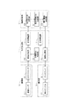
以下、本発明の第1の実施形態について、図面を参照しながら説明する。図1は、本実施形態における画像表示システムの構成を示すブロック図である。図1に示すように、本実施形態の画像表示システムは大きく分けて4つの機能部より構成されており、撮像映像を生成する撮像部10と、撮像映像を分離生成し撮像映像および表示映像に対して画像処理を行う処理伝送部11とを有する。さらに、位置合わせ演算、仮想現実CGを生成する各種演算ならびに表示映像に合成する処理を実行する演算合成部12と、表示映像を表示し体験者に映像を視認させる表示部13とを有している。
[First Embodiment]
Hereinafter, a first embodiment of the present invention will be described with reference to the drawings. FIG. 1 is a block diagram showing a configuration of an image display system in the present embodiment. As shown in FIG. 1, the image display system according to the present embodiment is roughly composed of four functional units. The
撮像部10および表示部13は本システムにおける画像表示装置に相当するヘッドマウントディスプレイ(以下、HMD)に備えられている。一方、処理伝送部11および演算合成部12は本システムにおける情報処理装置に相当するPCに備えられている。HMDおよび情報処理装置(PC)は互いに有線方式または無線方式により接続され、それぞれCPU、ROM、RAM等のハードウェア構成を備える。そして、CPUがROMやHD等に格納されたプログラムを実行することにより、例えば、後述する各機能構成やフローチャートの処理が実現される。RAMは、CPUがプログラムを展開して実行するワークエリアとして機能する記憶領域を有する。ROMは、CPUが実行するプログラム等を格納する記憶領域を有する。
The
撮像部10と表示部13を含むHMDにおいては、HMDを頭部に装着した体験者が外界の映像にCGを重畳した映像を見ることができ、現実空間と仮想空間がリアルタイムに融合した複合現実感を体験することができる。特に、ビデオシースルーHMDにおいては体験者の視線に略一致するよう、特定の位置姿勢から見た仮想現実物体をCGとして描画することが重要である。その際、この位置合わせのために加速度センサや角速度センサおよび地磁気センサならびにGPSなどを用いる技術が存在する。ただし、本実施形態においては撮像部10に撮像センサを搭載しているため、撮像映像内にマーカーや空間的な特徴点があれば、演算合成部12によって位置姿勢ならびにCGの重畳が高精度で実現できる。
In the HMD including the
この位置合わせ演算用の撮像映像は高解像であることよりも広画角であることが要求される。一方、ビデオシースルーの背景画像としてHMDの表示部13に表示するための撮像映像は表示画角に合わせて出来る限り高解像であることが望ましい。このように、システム後段における用途の違いにより、同一の撮像映像といえども要求の異なる複数種類の映像が混在する。そこで、本実施形態では、この特徴を利用して処理伝送部11において映像を分離し、システムの要求を満たしながらシステム全体の処理、伝送のデータ総量を抑える手法について説明する。
The imaged image for the alignment calculation is required to have a wide angle of view rather than high resolution. On the other hand, it is desirable that a captured image to be displayed on the
撮像部10は、撮像光学系である撮像レンズ100と撮像素子であるイメージセンサ101とを含み、撮像レンズ100を介して結像された現実空間における被写体像をイメージセンサ101による光電変換によって撮像映像を取得する。前述のとおり、位置合わせ演算のために撮像レンズ100は広画角であることが望ましい。イメージセンサ101は、例えばCMOSイメージセンサやCCDイメージセンサなどの半導体センサから構成され、高画素化ならびに高フレームレート化に伴い、取得される撮像映像となるデータ量は増大する。
The
表示部13は、表示プリズム131とディスプレイ132を含み、演算合成部12にて合成された表示映像をディスプレイ132に表示し、表示プリズム131を介して光束を観察対象者に結像させる。HMDの構成によっては、表示プリズム131はレンズでも構わないし、設けないようにすることも可能である。ディスプレイ132は、例えば液晶表示パネルや有機ELパネル等の表示素子により構成される。観察者への距離や表示プリズム131拡大率とディスプレイ132の大きさによって表示画角が決定され、解像度が高いほど視認性も向上するが、こちらも高画素化ならびに高フレームレート化に伴い、表示映像となるデータ量は増大する。
The
続いて、情報処理装置側に設けられている処理伝送部11および演算合成部12の機能について説明する。処理伝送部11(第1の生成部)は、同一の撮像映像から解像度変換ならびに領域の一部を切り出す切り出し処理によって、複数の映像を生成する画像分離部110と、解像度変換された撮像画像(第1の画像)を処理する画像処理部111とを有する。更に、切り出された撮像画像(第2の画像)を処理する画像処理部112と、表示画像を処理する画像処理部113とを有している。本実施形態では、画像分離部において撮像映像を2つに分離しているが、システム後段の要求によっては3つ以上に分離するようにしてもよい。
Next, functions of the
演算合成部12(第2の生成部)は、撮像映像からマーカーや特徴点を検出し体験者が使用するHMDの位置を割り出す位置合わせ演算部120と、その特定された位置から見た場合の仮想現実物体をCGとして描画する仮想現実CG生成部121とを有する。更に、表示部13の要求に基づき画像分離部110にて切り出された背景用画像と前記仮想現実CGを合成して表示画像とする表示画像合成部122を有している。これらの演算および合成処理は膨大な演算が必要となることが多く、高画素化に伴いより多くのシステムリソースを消費するため、ハイエンドPCやワークステーションなどが使用されることが多い。
The calculation synthesis unit 12 (second generation unit) detects a marker or a feature point from the captured image and determines the position of the HMD used by the experiencer, and the position when viewed from the specified position. A virtual reality
<データ分割処理の詳細>
次に、本実施形態の画像表示システムにおいて、HMDにより撮像された映像データ(画像)の分割処理について説明する。図2は、本実施形態に係るデータ分割処理の概略を示す概念図である。同図において、画像200はイメージセンサ101で撮影された撮像画像であり、ここでは例として3840×2160の4K映像とし、水平撮影画角も90°あるものとする。画像201は画像分離部110で解像度を変換した解像度変換画像であり、例として1920×1080のFullHD映像とし、水平画角は変わらず90°あるものとする。この際、解像度を変換する方法は画素混合や間引きなど様々な手法が存在するが、本実施形態はその手法によって限定されるものではなく、画角を保持したまま解像度を落とものであれば種々の方法を採用することが可能である。
<Details of data division processing>
Next, in the image display system according to the present embodiment, a process for dividing video data (image) captured by the HMD will be described. FIG. 2 is a conceptual diagram showing an outline of data division processing according to the present embodiment. In the figure, an
画像202は画像分離部110で切り出し処理を行った切り出し画像であり、例として2560×1440のWQHD映像とし、水平画角が64°とする。ここで、水平画角が64°となる理由は、90°ある元の画像から解像度すなわち画素密度をそのままに画像を切り出すためであって、切り出し比率によって計算される。また、この切り出される画角64°の画像は元となる画角90°の画像の一部に包含される。
An
処理203は、画像処理、映像伝送、位置合わせ演算や仮想現実CG演算、および表示画像合成といった一連の処理を総括的に示している。解像度やフレームレートが上がることによって処理203の負荷が増大することは前述したとおりであり、これを抑えるためには、事前に映像を分離することが有効となる。
A
画像204はディスプレイ132に表示される表示画像であり、例として2560×1440のWQHD映像とし、水平画角は64°となる。画像202は本画素数に合わせて切り出し処理が行われており、最終的な表示に必要な画角のうち最も高解像な状態となっている。
The
この一連の処理において、撮像された画像200は約8.3Mpixelとなるが、映像を分離した後の解像度変換画像201は約2.1Mpixelとなり、切り出し画像202の約3.7Mpixelとなる。すなわち、分離後の画像データのデータ量は、合計しても約5.8Mpixelと元の8.3Mpixelよりも小さくなる。したがって、元の撮像映像全てを処理伝送するよりもシステム全体の負荷を抑えることが可能となる。ここで、解像度変換画像201は位置合わせ演算部120の要求を、切り出し画像202はディスプレイ132の要求を満たしていることは言うまでも無い。また、必ずしもシステム後段の要求を満たさなくても、処理伝送の総量を下げることが優先事項であれば、元の撮像画像から解像度変換と切り出しを行う各々の比率によってデータ伝送量を抑えることも可能となる。いずれにせよ、本実施形態において解像度よりも画角が必要な位置合わせ演算用の映像と、表示に合わせた画角で高解像度な映像の2種類が必要であり、これをできるだけ事前に分離することで以降の処理、伝送の負荷を軽減することができる。
In this series of processing, the captured
続いて、図3を用いて、本実施形態における映像の伝送手順の処理フローについて説明する。同図において、ステップS300では、HMDの撮像部10により現実空間の画像を撮像し、それを処理伝送部11内の画像分離部110に送るここまでは、前述のとおり広画角かつ高解像な映像が伝送されている。なお、本実施形態では、以降の処理を、ステップS301〜S304と、ステップS305〜S306との並列処理としているが、本実施形態はこのような処理手順に限定されるものではない。
Next, a processing flow of a video transmission procedure in the present embodiment will be described with reference to FIG. In the figure, in step S300, an image of the real space is picked up by the HMD
ステップS301では、位置合わせ演算部120で行われる演算で要求される解像度に基づき、画像分離部110において撮像映像の解像度変換を行う。さらにステップS302では、解像度変換された映像の色補正やノイズリダクションなど各種画像処理を画像処理部111において行う。
In step S <b> 301, the
ステップS303では、演算合成部12内の位置合わせ演算部120において、撮像映像内のマーカーや空間的な特徴点を検出してHMD体験者の位置及び姿勢を演算から推定する。続くステップS304では、ステップS303において推定された位置姿勢情報を元に、仮想現実CG生成部121においてHMD体験者の位置および姿勢から見た場合の仮想現実物体をCGとして描画生成する。
In step S303, the
一方、ステップS305では、ステップS301との並列処理が開始され、イメージセンサ101で撮像された撮像映像から、表示画像合成部122もしくはディスプレイ132の仕様に基づいて要求される解像度の映像に画像分離部110で切り出しを行う。この際、切り出す画角は言うまでも無いが位置に関しても表示レンズの仕様に基づいて決定される。次に、ステップS306では、ステップS302と同様に、切り出された映像の各種画像処理を画像処理部112において行う。
On the other hand, in step S305, parallel processing with step S301 is started, and the image separation unit converts the captured image captured by the
ステップS307では、画像分離部110において切り出されたビデオシースルーHMDの背景に使用する撮像映像と仮想現実CG生成部121において生成された仮想現実CGとを表示画像合成部122において合成する。これが、ディスプレイ132に表示するための映像となる。ステップS308では、表示映像に対して輝度補正や色補正などの各種画像処理を画像処理部113において行う。ステップS309では、表示画像合成部122で合成され、画像処理部113で画像処理を行われた表示用映像を表示部13内のディスプレイ132に表示する。
In step S307, the captured image used for the background of the video see-through HMD cut out by the
以上の一連の処理により、HMD体験者は体験者の視線に略一致したビデオシースルー背景映像と、体験者の位置姿勢から見た仮想現実物体CGを重畳した仮想現実空間とをHMDを通して体験することが可能となる。本実施形態では、画像分離部110において解像度変換画像と切り出し画像に分離していることから、全ての撮像映像を処理伝送することに比べデータの総量が削減され、システム全体が肥大化することが抑制される。
Through the series of processes described above, the HMD user can experience through the HMD the video see-through background image that substantially matches the user's line of sight and the virtual reality space on which the virtual reality object CG viewed from the position and orientation of the user is superimposed. Is possible. In the present embodiment, since the
なお、上述の説明では、演算合成部12によって位置姿勢を推定しているが、位置姿勢の推定精度を更に高めるために、加速度センサや角速度センサおよび地磁気センサならびにGPSなどを更に用いるようにしてもよい。また、上述の説明では、解像度変換画像201を位置合わせ演算に用いる構成を示したが、この解像度変換画像201が他の処理に用いられるような構成であってもよい。その一例としては、例えば顔検出処理や物体認識処理に解像度変換画像201が用いる構成が考えられる。
In the above description, the position / orientation is estimated by the calculation /
[第2の実施形態]
次に、本発明の第2の実施形態について説明する。第2の実施形態は、画像表示システムのシステム構成の変化やシステムにおける処理転送状況に応じて、画像分離部110による解像度変換および画像切り出しの少なくとも一方を制御するものである。以下、図面を参照しつつ、本発明の第2の実施形態について説明する。なお、第1の実施形態で既に説明をした構成については、その説明を省略し、同一の符号を付す。
[Second Embodiment]
Next, a second embodiment of the present invention will be described. In the second embodiment, at least one of resolution conversion and image cropping by the
図4は、本実施形態に係る画像表示システムを示すブロック図である。本実施形態が第1の実施形態と異なる点は、処理伝送部11が更に分離設定制御部400を有することである。本実施形態のような画像表示システムにおいては、システム構成やシステムの処理伝送の状況が変化することが考えられる。システム構成が変化する例としては、演算合成部12に使用されるPCをユーザが交換した場合や、処理伝送部11と演算合成部12は変えずに撮像部10と表示部13を含むHMDが交換された場合などが挙げられる。また、システムの処理転送状況が変化する例としては、撮像部10によって撮像される映像データの内容により演算合成部12の負荷が変化し処理が追いつかないような状況がある。その他の例としては、伝送経路のパケットロスなどによる通信が不安定な状況において、実行スループットが下がり伝送のベストパフォーマンスを得られないという状況もある。そこで、本実施形態に係る画像表示システムは、このような状況に対応するために分離設定制御部400を備えている。
FIG. 4 is a block diagram showing the image display system according to this embodiment. The present embodiment is different from the first embodiment in that the
分離設定制御部400は、本システムの各部と接続しており、処理と伝送の状況を監視するものとする。そして、画像処理部111や位置合わせ演算部120の状況によって、システム全体のパフォーマンスが低下している場合は、画像分離部110に対して解像度変換の比率をさらに下げる指示を出す。この解像度変換量を変化させることによって、システム全体の処理伝送に係わるパフォーマンスが最適化され、システムを円滑に動作させることが可能となる。また、画像処理部112や表示画像合成部122の状況によっては、撮像映像の切り出し量を変化させたり、解像度変換と切り出し量の両方を変更するようにしてもよい。また、システム構成の変更が為されたときに、そのことをユーザに画像表示システムに備えられた入力手段により入力させ、その情報を分離設定制御部400が取得することにより、上述の解像度変換や切り出し量の変更の制御を行うようにしてもよい。
The separation
<データ分割処理の詳細>
次に、図5を用いて、本実施形態における映像の伝送手順の処理フローについて説明する。本実施形態の処理フローが、第1の実施形態と異なる点は、ステップS510〜S513が追加されていることである。ここでは、第1の実施形態との相違点についてのみ説明を行う。
<Details of data division processing>
Next, the processing flow of the video transmission procedure in this embodiment will be described with reference to FIG. The processing flow of this embodiment is different from that of the first embodiment in that steps S510 to S513 are added. Here, only differences from the first embodiment will be described.
まず、ステップS510では、分離設定制御部400から画像分離部110に対して出す指示方法が自動設定モードか否かを判断する。ここで、自動設定モードとは、本システムが自動で処理伝送の状況に応じてアクティブに映像分離の設定を行うモードである。自動設定モードの場合はステップS511へ処理が移り、自動設定モードで無い場合はステップS513へ処理が移る。
First, in step S510, it is determined whether or not the instruction method issued from the separation
ステップS511は、自動設定モードの場合に、システム各部と接続された分離設定制御部400がシステム各部からのフィードバックに基づいて、変換する最適な解像度ならびに最適な切り出し量を自動で演算し、画像分離部110に対する設定値を取得する。次に、ステップS512は、分離設定制御部400から画像分離部110に対して、ステップS511で演算された設定値に基づいた指示を出す。
In step S511, in the automatic setting mode, the separation
ステップS513は、自動設定モードで無い場合に、ユーザからの分離設定値を取得する。この場合、システムに設定された初期値を用いることも可能であり、システム変更に応じてユーザから事前に入力された設定値を用いることも可能である。分離設定制御部400は、いずれかの設定値を取得することで、ステップS512において画像分離部110に対して指示を出す。ステップS512以降の処理は、第1の実施形態で説明した構成と同様である。
Step S513 acquires the separation setting value from the user when not in the automatic setting mode. In this case, it is possible to use an initial value set in the system, and it is also possible to use a setting value input in advance by the user in accordance with a system change. The separation
以上、本実施形態によれば、映像データの分離設定を能動的に変化させることが可能となり、システム全体のパフォーマンスが最適となるよう映像データの処理伝送量を抑制することが可能となる。 As described above, according to the present embodiment, it is possible to actively change the separation setting of the video data, and it is possible to suppress the processing transmission amount of the video data so that the performance of the entire system is optimized.
[その他の実施形態]
上述の説明では、HMD側が撮像部10と表示部13とを備え、情報処理装置(PC)側が処理伝送部11と演算合成部12とを備える構成を示した。しかしながら、本発明は、このような形態に限定されるものではなく、例えば、上記4つの機能部の全てをHMD側が有し、HMD側だけで全ての処理が実行されるように構成してもよい。
[Other Embodiments]
In the above description, a configuration in which the HMD side includes the
また、本発明は、上記実施形態の機能を実現するソフトウェア(プログラム)を、ネットワーク又は各種記憶媒体を介してシステム或いは装置に供給し、そのシステム或いは装置のコンピュータ(又はCPUやMPU等)がプログラムを読出し実行する処理である。また、本発明は、複数の機器から構成されるシステムに適用しても、1つの機器からなる装置に適用してもよい。本発明は上記実施例に限定されるものではなく、本発明の趣旨に基づき種々の変形(各実施例の有機的な組合せを含む)が可能であり、それらを本発明の範囲から除外するものではない。即ち、上述した各実施例及びその変形例を組み合わせた構成も全て本発明に含まれるものである。 In addition, the present invention supplies software (program) for realizing the functions of the above-described embodiments to a system or apparatus via a network or various storage media, and the computer of the system or apparatus (or CPU, MPU, etc.) programs Is read and executed. Further, the present invention may be applied to a system composed of a plurality of devices or an apparatus composed of a single device. The present invention is not limited to the above embodiments, and various modifications (including organic combinations of the embodiments) are possible based on the spirit of the present invention, and these are excluded from the scope of the present invention. is not. That is, the present invention includes all the combinations of the above-described embodiments and modifications thereof.
10 撮像部
11 処理伝送部
12 演算合成部
13 表示部
DESCRIPTION OF
Claims (11)
前記撮像部により撮像された画像を取得し、当該画像から第1の画像と第2の画像とを生成する第1の生成部と、
前記第1の生成手段により生成された第1の画像および第2の画像に基づいて、前記表示部によってユーザに表示すべき表示画像を生成する第2の生成部と、を有し、
前記第1の生成部は、前記第1の画像と第2の画像との合計のデータ量が前記撮像部により撮像された画像のデータ量よりも小さくなるように、前記第1の画像と第2の画像とを生成することを特徴とする情報処理装置。 An information processing apparatus connected to an image display apparatus comprising: an imaging unit that captures an image; and a display unit that displays a display image to be displayed to a user,
A first generation unit that acquires an image captured by the imaging unit and generates a first image and a second image from the image;
A second generation unit that generates a display image to be displayed to a user by the display unit based on the first image and the second image generated by the first generation unit;
The first generation unit includes the first image and the second image so that a total data amount of the first image and the second image is smaller than a data amount of an image captured by the imaging unit. An information processing apparatus that generates two images.
前記撮像部により撮像された画像から第1の画像と第2の画像とを生成する第1の生成部と、
前記第1の生成手段により生成された第1の画像および第2の画像に基づいて、ユーザに表示すべき表示画像を生成する第2の生成部と、
前記第2の生成手段により生成された表示画像を表示する表示部と、を有し、
前記第1の生成部は、前記第1の画像と第2の画像との合計のデータ量が前記撮像部により撮像された画像のデータ量よりも小さくなるように、前記第1の画像と第2の画像とを生成することを特徴とする画像表示装置。 An imaging unit that captures an image;
A first generation unit that generates a first image and a second image from an image captured by the imaging unit;
A second generator for generating a display image to be displayed to the user based on the first image and the second image generated by the first generator;
A display unit for displaying the display image generated by the second generation unit,
The first generation unit includes the first image and the second image so that a total data amount of the first image and the second image is smaller than a data amount of an image captured by the imaging unit. 2. An image display device that generates two images.
前記撮像部により撮像された画像から第1の画像と第2の画像とを生成する第1の生成部と、
前記第1の生成手段により生成された第1の画像および第2の画像に基づいて、ユーザに表示すべき表示画像を生成する第2の生成部と、
前記第2の生成手段により生成された表示画像を表示する表示部と、を有し、
前記第1の生成部は、前記第1の画像と第2の画像との合計のデータ量が前記撮像部により撮像された画像のデータ量よりも小さくなるように、前記第1の画像と第2の画像とを生成することを特徴とする画像表示システム。 An imaging unit that captures an image;
A first generation unit that generates a first image and a second image from an image captured by the imaging unit;
A second generator for generating a display image to be displayed to the user based on the first image and the second image generated by the first generator;
A display unit for displaying the display image generated by the second generation unit,
The first generation unit includes the first image and the second image so that a total data amount of the first image and the second image is smaller than a data amount of an image captured by the imaging unit. 2. An image display system characterized by generating two images.
前記撮像部により撮像された画像を取得し、当該画像から第1の画像と第2の画像とを生成する第1の生成ステップと、
前記第1の生成ステップにおいて生成された第1の画像および第2の画像に基づいて、前記表示部によってユーザに表示すべき表示画像を生成する第2の生成ステップと、を有し、
前記第1の生成ステップは、前記第1の画像と第2の画像との合計のデータ量が前記撮像部により撮像された画像のデータ量よりも小さくなるように、前記第1の画像と第2の画像とを生成することを特徴とする情報処理方法。 An information processing method in an information processing apparatus connected to an image display apparatus comprising: an imaging unit that captures an image; and a display unit that displays a display image to be displayed to a user,
A first generation step of acquiring an image captured by the imaging unit and generating a first image and a second image from the image;
A second generation step of generating a display image to be displayed to the user by the display unit based on the first image and the second image generated in the first generation step;
The first generation step includes the first image and the second image so that a total data amount of the first image and the second image is smaller than a data amount of the image captured by the imaging unit. An information processing method characterized by generating two images.
Priority Applications (2)
| Application Number | Priority Date | Filing Date | Title |
|---|---|---|---|
| JP2016064704A JP2017181605A (en) | 2016-03-28 | 2016-03-28 | Information processor, image display apparatus, image display system, and information processing method |
| US15/464,834 US10616504B2 (en) | 2016-03-28 | 2017-03-21 | Information processing device, image display device, image display system, and information processing method |
Applications Claiming Priority (1)
| Application Number | Priority Date | Filing Date | Title |
|---|---|---|---|
| JP2016064704A JP2017181605A (en) | 2016-03-28 | 2016-03-28 | Information processor, image display apparatus, image display system, and information processing method |
Publications (2)
| Publication Number | Publication Date |
|---|---|
| JP2017181605A true JP2017181605A (en) | 2017-10-05 |
| JP2017181605A5 JP2017181605A5 (en) | 2019-07-11 |
Family
ID=59899096
Family Applications (1)
| Application Number | Title | Priority Date | Filing Date |
|---|---|---|---|
| JP2016064704A Pending JP2017181605A (en) | 2016-03-28 | 2016-03-28 | Information processor, image display apparatus, image display system, and information processing method |
Country Status (2)
| Country | Link |
|---|---|
| US (1) | US10616504B2 (en) |
| JP (1) | JP2017181605A (en) |
Families Citing this family (1)
| Publication number | Priority date | Publication date | Assignee | Title |
|---|---|---|---|---|
| JP6551316B2 (en) * | 2016-06-10 | 2019-07-31 | 京セラドキュメントソリューションズ株式会社 | Image reading apparatus and image forming apparatus |
Citations (4)
| Publication number | Priority date | Publication date | Assignee | Title |
|---|---|---|---|---|
| JP2003199074A (en) * | 2001-12-25 | 2003-07-11 | Nec Corp | Video image presentation system, video image transmission device, video image presentation device and video image processing program |
| JP2007081465A (en) * | 2005-09-09 | 2007-03-29 | Canon Inc | Remote controller and imaging apparatus |
| JP2010092436A (en) * | 2008-10-10 | 2010-04-22 | Canon Inc | Image processor and image processing method |
| JP2014199527A (en) * | 2013-03-29 | 2014-10-23 | キヤノン株式会社 | Information processor, information processing method and program |
Family Cites Families (8)
| Publication number | Priority date | Publication date | Assignee | Title |
|---|---|---|---|---|
| JP3613983B2 (en) * | 1998-06-25 | 2005-01-26 | ソニー株式会社 | Image generating apparatus and method, and electronic still camera |
| JP2011071965A (en) * | 2009-08-28 | 2011-04-07 | Sanyo Electric Co Ltd | Image editing device and imaging device provided with the image editing device, image reproduction device and imaging device provided with the image reproduction device |
| US8576293B2 (en) * | 2010-05-18 | 2013-11-05 | Aptina Imaging Corporation | Multi-channel imager |
| JP2013251781A (en) | 2012-06-01 | 2013-12-12 | Canon Inc | Imaging apparatus |
| US10074158B2 (en) * | 2014-07-08 | 2018-09-11 | Qualcomm Incorporated | Systems and methods for stereo depth estimation using global minimization and depth interpolation |
| US9448704B1 (en) * | 2015-04-29 | 2016-09-20 | Dropbox, Inc. | Navigating digital content using visual characteristics of the digital content |
| US10962780B2 (en) * | 2015-10-26 | 2021-03-30 | Microsoft Technology Licensing, Llc | Remote rendering for virtual images |
| US10114465B2 (en) * | 2016-01-15 | 2018-10-30 | Google Llc | Virtual reality head-mounted devices having reduced numbers of cameras, and methods of operating the same |
-
2016
- 2016-03-28 JP JP2016064704A patent/JP2017181605A/en active Pending
-
2017
- 2017-03-21 US US15/464,834 patent/US10616504B2/en active Active
Patent Citations (4)
| Publication number | Priority date | Publication date | Assignee | Title |
|---|---|---|---|---|
| JP2003199074A (en) * | 2001-12-25 | 2003-07-11 | Nec Corp | Video image presentation system, video image transmission device, video image presentation device and video image processing program |
| JP2007081465A (en) * | 2005-09-09 | 2007-03-29 | Canon Inc | Remote controller and imaging apparatus |
| JP2010092436A (en) * | 2008-10-10 | 2010-04-22 | Canon Inc | Image processor and image processing method |
| JP2014199527A (en) * | 2013-03-29 | 2014-10-23 | キヤノン株式会社 | Information processor, information processing method and program |
Also Published As
| Publication number | Publication date |
|---|---|
| US20170280062A1 (en) | 2017-09-28 |
| US10616504B2 (en) | 2020-04-07 |
Similar Documents
| Publication | Publication Date | Title |
|---|---|---|
| US20200051269A1 (en) | Hybrid depth sensing pipeline | |
| JP6344723B2 (en) | Video display system, video display device, and video display method | |
| WO2012029576A1 (en) | Mixed reality display system, image providing server, display apparatus, and display program | |
| WO2015060393A1 (en) | Remote action guidance system and processing method therefor | |
| JP6904684B2 (en) | Image processing equipment, image processing methods, and programs | |
| US10750080B2 (en) | Information processing device, information processing method, and program | |
| WO2021261248A1 (en) | Image processing device, image display system, method, and program | |
| JP6711670B2 (en) | Information processing device, image display device, image display system, and information processing method | |
| US11373273B2 (en) | Method and device for combining real and virtual images | |
| JP6137910B2 (en) | Information processing apparatus, information processing method, and program | |
| JP2018157578A (en) | Video display system, video display device and video display method | |
| JP2017181605A (en) | Information processor, image display apparatus, image display system, and information processing method | |
| JP6858007B2 (en) | Image processing system, image processing method | |
| JP5509986B2 (en) | Image processing apparatus, image processing system, and image processing program | |
| WO2017086355A1 (en) | Transmission device, transmission method, reception device, reception method, and transmission/reception system | |
| JP2014199508A (en) | Image processing apparatus, image processing method, and program | |
| JP7000066B2 (en) | Image processing equipment, image processing methods, and programs | |
| JP6008711B2 (en) | Image processing apparatus, image processing method, and program | |
| JP2017010119A (en) | Information processing device, image processing device, control method for those, and program | |
| JP6614835B2 (en) | COMMUNICATION DEVICE, HEAD MOUNT DISPLAY, IMAGE PROCESSING SYSTEM, COMMUNICATION METHOD, AND PROGRAM | |
| JP6702779B2 (en) | Data distribution device, image display system, and data distribution method | |
| JP2017098921A (en) | Transmission device, transmission method, and program | |
| WO2018016655A1 (en) | Instructing device, method of controlling instructing device, remote operation support system, and information processing program | |
| WO2018084051A1 (en) | Information processing device, head-mounted display, information processing system, and information processing method | |
| JP2015167281A (en) | image processing system and image processing program |
Legal Events
| Date | Code | Title | Description |
|---|---|---|---|
| A621 | Written request for application examination |
Free format text: JAPANESE INTERMEDIATE CODE: A621 Effective date: 20190319 |
|
| A521 | Request for written amendment filed |
Free format text: JAPANESE INTERMEDIATE CODE: A523 Effective date: 20190605 |
|
| A977 | Report on retrieval |
Free format text: JAPANESE INTERMEDIATE CODE: A971007 Effective date: 20200128 |
|
| A131 | Notification of reasons for refusal |
Free format text: JAPANESE INTERMEDIATE CODE: A131 Effective date: 20200212 |
|
| A601 | Written request for extension of time |
Free format text: JAPANESE INTERMEDIATE CODE: A601 Effective date: 20200403 |
|
| A521 | Request for written amendment filed |
Free format text: JAPANESE INTERMEDIATE CODE: A523 Effective date: 20200407 |
|
| A131 | Notification of reasons for refusal |
Free format text: JAPANESE INTERMEDIATE CODE: A131 Effective date: 20200804 |
|
| A521 | Request for written amendment filed |
Free format text: JAPANESE INTERMEDIATE CODE: A523 Effective date: 20201001 |
|
| A02 | Decision of refusal |
Free format text: JAPANESE INTERMEDIATE CODE: A02 Effective date: 20210309 |