JP2017172936A - Hot water supply system - Google Patents

Hot water supply system Download PDF

Info

Publication number
JP2017172936A
JP2017172936A JP2016062268A JP2016062268A JP2017172936A JP 2017172936 A JP2017172936 A JP 2017172936A JP 2016062268 A JP2016062268 A JP 2016062268A JP 2016062268 A JP2016062268 A JP 2016062268A JP 2017172936 A JP2017172936 A JP 2017172936A
Authority
JP
Japan
Prior art keywords
hot water
water supply
information
amount
display
Prior art date
Legal status (The legal status is an assumption and is not a legal conclusion. Google has not performed a legal analysis and makes no representation as to the accuracy of the status listed.)
Granted
Application number
JP2016062268A
Other languages
Japanese (ja)
Other versions
JP6623881B2 (en
Inventor
一樹 池田
Kazuki Ikeda
一樹 池田
圭 ▲柳▼本
圭 ▲柳▼本
Kei Yanagimoto
康史 本庄
Yasushi Honjo
康史 本庄
正俊 柳下
Masatoshi Yagishita
正俊 柳下
明宏 戸田
Akihiro Toda
明宏 戸田
Current Assignee (The listed assignees may be inaccurate. Google has not performed a legal analysis and makes no representation or warranty as to the accuracy of the list.)
Mitsubishi Electric Corp
Original Assignee
Mitsubishi Electric Corp
Priority date (The priority date is an assumption and is not a legal conclusion. Google has not performed a legal analysis and makes no representation as to the accuracy of the date listed.)
Filing date
Publication date
Application filed by Mitsubishi Electric Corp filed Critical Mitsubishi Electric Corp
Priority to JP2016062268A priority Critical patent/JP6623881B2/en
Publication of JP2017172936A publication Critical patent/JP2017172936A/en
Application granted granted Critical
Publication of JP6623881B2 publication Critical patent/JP6623881B2/en
Active legal-status Critical Current
Anticipated expiration legal-status Critical

Links

Images

Abstract

PROBLEM TO BE SOLVED: To provide a hot water supply system capable of surely notifying a user of information on a hot water supply amount, without deteriorating convenience in displaying of information on setting of an operation state of a water heater or setting of the water heater.SOLUTION: During execution of hot water supply from a water heater, or during non-execution of hot water supply from the water heater except for after stop of hot water supply, at least one information of first information on setting of the water heater and second information on a state of the water heater is displayed on display means (top screen 31). After hot water supply from the water heater is stopped, third information on a hot water supply amount from start to stop of the hot water supply is temporarily displayed on the display means, instead of the one information of the first and second information (first guidance screen 32).SELECTED DRAWING: Figure 4

Description

本発明は、給湯システムに関する。   The present invention relates to a hot water supply system.

下記特許文献1には、以下のような給湯機が開示されている。給湯動作開始から設定時間内に積算給湯量が所定の積算給湯量に達した場合に、操作端末の表示部に給湯動作開始からの給湯使用量をポップアップ表示する。給湯動作開始から設定時間経過すると、ポップアップ表示とは異なる種類の報知を行う。   The following Patent Document 1 discloses a water heater as follows. When the integrated hot water supply amount reaches a predetermined integrated hot water supply amount within a set time from the start of the hot water supply operation, the hot water usage amount from the start of the hot water supply operation is displayed in a pop-up on the display unit of the operation terminal. When a set time has elapsed from the start of the hot water supply operation, a different type of notification from the pop-up display is performed.

特開2013−245846号公報JP 2013-245846 A

給湯機には、複数の端末装置が接続されることが多い。複数の端末装置は、例えば、浴室リモコン及び台所リモコンである。端末装置の表示部には、通常は、給湯機の運転状態あるいは給湯機の設定に関する情報、例えば、わき上げ設定及び湯はり状態などの情報を表示している。特許文献1の技術では、給湯動作の実行中に、給湯使用量がポップアップ表示される。このため、シャワーあるいは食器洗いなどの長時間の給湯使用において、給湯使用量がポップアップ表示されたときに、複数のリモコンのうちの他のリモコンを見ている他のユーザーは、給湯機の運転状態あるいは給湯機の設定に関する情報を見られなくなり、利便性が悪いという問題がある。   A plurality of terminal devices are often connected to the water heater. The plurality of terminal devices are, for example, a bathroom remote controller and a kitchen remote controller. The display unit of the terminal device normally displays information related to the operation state of the water heater or the setting of the water heater, for example, information such as the lift setting and the hot water state. In the technique of Patent Document 1, the amount of hot water supply used is displayed in a pop-up while the hot water supply operation is being executed. For this reason, when using hot water for a long time such as showering or washing dishes, when the amount of hot water used is displayed as a pop-up, other users watching other remote controllers among the plurality of remote controllers may There is a problem that information regarding the setting of the water heater cannot be seen, and convenience is poor.

本発明は、上述のような課題を解決するためになされたもので、給湯機の運転状態あるいは給湯機の設定に関する情報の表示を見ることの利便性を低下させることなく、給湯量に関する情報をユーザーに確実に知らせることのできる給湯システムを提供することを目的とする。   The present invention has been made to solve the above-described problems, and does not reduce the convenience of seeing the display of information related to the operating state of the water heater or the setting of the water heater, so that information relating to the amount of hot water can be obtained. An object of the present invention is to provide a hot water supply system capable of reliably informing a user.

本発明に係る給湯システムは、給湯機と、給湯機からの給湯が実行されているか否かを検知する手段と、給湯機からの給湯量を計算する手段と、表示手段と、表示手段の表示を制御する制御手段と、を備え、給湯機からの給湯の実行中のとき、及び、給湯停止後を除く給湯機からの給湯の非実行中のときには、給湯機の設定に関する第一情報及び給湯機の状態に関する第二情報の少なくとも一方の情報が表示手段に表示され、給湯機からの給湯が停止した後には当該給湯の開始から停止までの給湯量に関する第三情報が、第一情報及び第二情報の少なくとも一方の情報に代えて、一時的に表示手段に表示されるものである。   A hot water supply system according to the present invention includes a water heater, means for detecting whether hot water is being supplied from the water heater, means for calculating the amount of hot water supplied from the water heater, display means, and display of the display means. Control means for controlling the hot water supply when the hot water supply from the water heater is being executed and when hot water is not being supplied from the hot water heater except after the hot water supply is stopped. At least one of the second information related to the state of the machine is displayed on the display means, and after the hot water supply from the water heater is stopped, the third information about the amount of hot water supply from the start to the stop of the hot water supply is the first information and the first information Instead of at least one of the two pieces of information, the information is temporarily displayed on the display means.

本発明の給湯システムによれば、給湯機の運転状態あるいは給湯機の設定に関する情報の表示を見ることの利便性を低下させることなく、給湯量に関する情報をユーザーに確実に知らせることが可能となる。   According to the hot water supply system of the present invention, it is possible to reliably notify the user of information relating to the amount of hot water supply without deteriorating the convenience of viewing the display of information relating to the operating state of the water heater or the setting of the water heater. .

実施の形態1の給湯システムを示す図である。It is a figure which shows the hot water supply system of Embodiment 1. FIG. 実施の形態1の給湯システムが備える台所リモコンの外観図である。It is an external view of the kitchen remote control with which the hot-water supply system of Embodiment 1 is provided. 実施の形態1の給湯システムの制御動作を示すフローチャートである。3 is a flowchart illustrating a control operation of the hot water supply system according to the first embodiment. 実施の形態1の給湯システムのガイダンス表示を示す図である。It is a figure which shows the guidance display of the hot water supply system of Embodiment 1. FIG.

以下、図面を参照して実施の形態について説明する。各図において共通する要素には、同一の符号を付して、重複する説明を簡略化または省略する。本開示は、以下の実施の形態で説明する構成のうち、組合わせ可能な構成のあらゆる組合わせを含み得る。   Hereinafter, embodiments will be described with reference to the drawings. Elements common to the drawings are denoted by the same reference numerals, and redundant description is simplified or omitted. The present disclosure may include any combination of configurations that can be combined among the configurations described in the following embodiments.

実施の形態1.
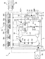
図1は、実施の形態1の給湯システム1を示す図である。図1に示すように、実施の形態1の給湯システム1は、貯湯式給湯機2、台所リモコン25、及び浴室リモコン26を備える。台所リモコン25は、台所に設置される。浴室リモコン26は、浴室に設置される端末装置の例である。台所リモコン25は、浴室以外の場所に設置される端末装置の例である。給湯システム1は、台所リモコン25に代えて、または台所リモコン25に加えて、浴室及び台所以外の場所に設置される他の端末装置を備えてもよい。
Embodiment 1 FIG.
FIG. 1 shows a hot water supply system 1 according to the first embodiment. As shown in FIG. 1, the hot water supply system 1 according to the first embodiment includes a hot water storage type hot water heater 2, a kitchen remote control 25, and a bathroom remote control 26. The kitchen remote control 25 is installed in the kitchen. The bathroom remote control 26 is an example of a terminal device installed in a bathroom. The kitchen remote control 25 is an example of a terminal device installed in a place other than the bathroom. The hot water supply system 1 may include another terminal device installed in a place other than the bathroom and the kitchen instead of or in addition to the kitchen remote control 25.

貯湯式給湯機2は、貯湯ユニット3及びヒートポンプユニット28を備える。ヒートポンプユニット28は、水を加熱する加熱手段の例である。ヒートポンプユニット28には、圧縮機、水冷媒熱交換器、例えば膨張弁などの減圧装置、及び、蒸発器である空気熱交換器を冷媒配管で順次接続した冷凍サイクル装置(図示省略)が備えられている。   The hot water storage type water heater 2 includes a hot water storage unit 3 and a heat pump unit 28. The heat pump unit 28 is an example of a heating unit that heats water. The heat pump unit 28 is provided with a refrigeration cycle device (not shown) in which a compressor, a water refrigerant heat exchanger, for example, a decompression device such as an expansion valve, and an air heat exchanger as an evaporator are sequentially connected by refrigerant piping. ing.

貯湯ユニット3内には、貯湯タンク4が備えられている。貯湯タンク4は、蓄熱回路24を介して、ヒートポンプユニット28に接続されている。蓄熱回路24は、貯湯タンク4の下部とヒートポンプユニット28の水冷媒熱交換器の水の入口とを接続する通路と、水冷媒熱交換器の水の出口と貯湯タンク4の上部とを接続する通路とを有する。蓄熱回路24の途中には循環ポンプ27が配置されている。   A hot water storage tank 4 is provided in the hot water storage unit 3. The hot water storage tank 4 is connected to the heat pump unit 28 via the heat storage circuit 24. The heat storage circuit 24 connects a passage connecting the lower part of the hot water storage tank 4 and the water inlet of the water refrigerant heat exchanger of the heat pump unit 28, the water outlet of the water refrigerant heat exchanger, and the upper part of the hot water storage tank 4. And a passage. A circulation pump 27 is disposed in the middle of the heat storage circuit 24.

貯湯タンク4の内部には、温度の違いによる水の密度の差により、上側が高温で下側が低温になる温度成層を形成できる。貯湯タンク4には、貯湯タンク4の内部の鉛直方向の温度分布を検知するための複数の温度センサが配置されている。本実施の形態では、以下の温度センサが配置されている。第1の温度センサ5aは、貯湯タンク4の最上部からの容積が0Lの位置、すなわち貯湯タンク4の最上部の位置にある。第2の温度センサ5bは、貯湯タンク4の最上部からの容積が50Lの位置にある。第3の温度センサ5cは、貯湯タンク4の最上部からの容積が100Lの位置にある。第4の温度センサ5dは、貯湯タンク4の最上部からの容積が150Lの位置にある。本実施の形態では、温度センサ5a〜5dで検知される温度により、貯湯タンク4内にある湯量及び熱量を検知できる。   Inside the hot water storage tank 4, a temperature stratification can be formed in which the upper side is high temperature and the lower side is low temperature due to the difference in water density due to the temperature difference. The hot water storage tank 4 is provided with a plurality of temperature sensors for detecting the temperature distribution in the vertical direction inside the hot water storage tank 4. In the present embodiment, the following temperature sensors are arranged. The first temperature sensor 5 a is located at a position where the volume from the top of the hot water storage tank 4 is 0 L, that is, at the top of the hot water storage tank 4. The second temperature sensor 5b is located at a position where the volume from the top of the hot water storage tank 4 is 50L. The third temperature sensor 5c is located at a position where the volume from the top of the hot water storage tank 4 is 100L. The fourth temperature sensor 5d is at a position where the volume from the top of the hot water storage tank 4 is 150L. In the present embodiment, the amount of hot water and the amount of heat in the hot water storage tank 4 can be detected based on the temperatures detected by the temperature sensors 5a to 5d.

貯湯式給湯機2は、蓄熱運転を実施できる。蓄熱運転は、高温の湯を貯湯タンク4に蓄積する運転である。蓄熱運転は、貯湯タンク4の蓄熱量を増加させる運転である。蓄熱運転では、以下のようになる。循環ポンプ27及びヒートポンプユニット28が運転される。貯湯タンク4の下部から取り出された水がヒートポンプユニット28内の水冷媒熱交換器に導かれる。温度センサ5eは、ヒートポンプユニット28に入る水の温度を検知する。水冷媒熱交換器で加熱されることで高温になった湯が、貯湯タンク4へ戻り、貯湯タンク4の上部に流入する。貯湯タンク4の上部に対する蓄熱回路24の接続位置には、温度センサ6が配置されている。温度センサ6によれば、ヒートポンプユニット28から貯湯タンク4の上部へ戻る湯の温度を検知できる。   The hot water storage type water heater 2 can perform a heat storage operation. The heat storage operation is an operation for accumulating high-temperature hot water in the hot water storage tank 4. The heat storage operation is an operation for increasing the heat storage amount of the hot water storage tank 4. In the heat storage operation, it is as follows. The circulation pump 27 and the heat pump unit 28 are operated. The water taken out from the lower part of the hot water storage tank 4 is guided to the water / refrigerant heat exchanger in the heat pump unit 28. The temperature sensor 5e detects the temperature of water entering the heat pump unit 28. Hot water that has been heated by the water-refrigerant heat exchanger returns to the hot water storage tank 4 and flows into the upper portion of the hot water storage tank 4. A temperature sensor 6 is disposed at a connection position of the heat storage circuit 24 with respect to the upper part of the hot water storage tank 4. According to the temperature sensor 6, the temperature of hot water returning from the heat pump unit 28 to the upper part of the hot water storage tank 4 can be detected.

一般給湯側電動混合弁7は、貯湯タンク4の上部に接続された給湯管8を通って供給される湯すなわち高温水と、水道管等の水源に接続された給水管9を通って供給される低温水とを混合することにより、設定温度の湯を生成する。その湯は、混合給湯管10を経由して、蛇口(図示省略)へ供給される。本明細書において、「蛇口」とは、例えば、浴室にあるシャワー及び給湯栓、流し台の給湯栓、洗面台の給湯栓などを含みうる。   The general hot water supply side electric mixing valve 7 is supplied through hot water supplied through a hot water supply pipe 8 connected to the upper part of the hot water storage tank 4, that is, hot water, and through a water supply pipe 9 connected to a water source such as a water pipe. By mixing with low-temperature water, hot water having a set temperature is generated. The hot water is supplied to a faucet (not shown) via the mixed hot water supply pipe 10. In this specification, the “faucet” may include, for example, a shower and a hot water tap in a bathroom, a hot water tap of a sink, a hot water tap of a wash basin, and the like.

給水管9には、給水温度センサ23が設けられ、給水管9を流れる水の温度を検知する。混合給湯管10には、給湯用流量センサ19及び給湯用温度センサ20が設置されている。給湯用流量センサ19は、蛇口への給湯流量を検知する。給湯用温度センサ20は、蛇口への給湯温度を検知する。   The water supply pipe 9 is provided with a water supply temperature sensor 23 to detect the temperature of the water flowing through the water supply pipe 9. The mixed hot water supply pipe 10 is provided with a hot water flow rate sensor 19 and a hot water temperature sensor 20. The hot water supply flow rate sensor 19 detects the hot water supply flow rate to the faucet. The hot water supply temperature sensor 20 detects the hot water supply temperature to the faucet.

風呂給湯側電動混合弁11は、給湯管8を通って供給される湯すなわち高温水と、給水管9を通って供給される低温水とを混合することにより、設定温度の湯を生成する。その湯は、混合風呂管18、風呂側循環回路12を経由して、浴室にある浴槽(図示省略)へ供給される。貯湯式給湯機2は、浴槽への湯はりを行う湯はり動作を実施できる。湯はり動作では、給湯の開始及び停止は、混合風呂管18に設けられた電磁弁13により制御される。混合風呂管18には、風呂用流量センサ21及び風呂用温度センサ22が設置されている。風呂用流量センサ21は、浴槽への給湯流量を検知する。風呂用温度センサ22は、浴槽への給湯温度を検知する。一般給湯側電動混合弁7及び風呂給湯側電動混合弁11は、高温水と低温水とを混合することで給湯温度を調整する混合手段の例である。   The hot water supply side electric mixing valve 11 generates hot water having a set temperature by mixing hot water supplied through the hot water supply pipe 8, that is, high temperature water, and low temperature water supplied through the water supply pipe 9. The hot water is supplied to a bathtub (not shown) in the bathroom via the mixed bath pipe 18 and the bath-side circulation circuit 12. The hot water storage type water heater 2 can perform hot water operation for hot water to the bathtub. In the hot water operation, the start and stop of hot water supply are controlled by an electromagnetic valve 13 provided in the mixed bath pipe 18. The mixed bath pipe 18 is provided with a bath flow sensor 21 and a bath temperature sensor 22. The bath flow sensor 21 detects the hot water flow rate to the bathtub. The bath temperature sensor 22 detects the hot water supply temperature to the bathtub. The general hot water supply side electric mixing valve 7 and the bath hot water supply side electric mixing valve 11 are examples of mixing means for adjusting the hot water supply temperature by mixing high temperature water and low temperature water.

風呂側循環回路12は、風呂循環ポンプ14により浴槽から浴槽水を引き込み、熱交換器15を経由して浴槽に戻る経路である。タンク側循環回路16は、貯湯タンク4の上部から貯湯タンク4内の湯を循環ポンプ17で引き込み、熱交換器15を経由して貯湯タンク4の下部に繋がる経路である。貯湯式給湯機2は、浴槽に貯留された浴槽水を加熱する追い焚き動作を実施できる。追い焚き動作時には、以下のようになる。風呂循環ポンプ14及び循環ポンプ17が運転される。風呂循環ポンプ14により浴槽から風呂側循環回路12に引き込まれた浴槽水と、循環ポンプ17により貯湯タンク4の上部からタンク側循環回路16に引き込まれた高温湯とが、熱交換器15にて熱を交換する。熱交換器15で加熱された浴槽水が浴槽へ戻る。浴槽温度が設定温度まで上昇したことを検知したときに、風呂循環ポンプ14及び循環ポンプ17の動作を停止することで、追い焚き動作を自動的に終了してもよい。   The bath-side circulation circuit 12 is a path that draws bath water from the bathtub by the bath circulation pump 14 and returns to the bathtub via the heat exchanger 15. The tank-side circulation circuit 16 is a path that draws hot water in the hot water storage tank 4 from the upper part of the hot water storage tank 4 by the circulation pump 17 and is connected to the lower part of the hot water storage tank 4 via the heat exchanger 15. The hot water storage type water heater 2 can perform a reheating operation for heating the bathtub water stored in the bathtub. At the time of chasing, it will be as follows. The bath circulation pump 14 and the circulation pump 17 are operated. Bath water drawn into the bath-side circulation circuit 12 from the bathtub by the bath circulation pump 14 and high-temperature hot water drawn into the tank-side circulation circuit 16 from the upper part of the hot water storage tank 4 by the circulation pump 17 in the heat exchanger 15. Exchange heat. The bathtub water heated by the heat exchanger 15 returns to the bathtub. When it is detected that the bath temperature has risen to the set temperature, the chasing operation may be automatically ended by stopping the operation of the bath circulation pump 14 and the circulation pump 17.

貯湯式給湯機2は、制御装置50を備える。ヒートポンプユニット28、循環ポンプ27、温度センサ5a〜5e、温度センサ6、一般給湯側電動混合弁7、風呂給湯側電動混合弁11、電磁弁13、風呂循環ポンプ14、循環ポンプ17、給湯用流量センサ19、給湯用温度センサ20、風呂用流量センサ21、風呂用温度センサ22、及び給水温度センサ23は、それぞれ、制御装置50に対して電気的に接続されている。台所リモコン25及び浴室リモコン26は、制御装置50に対して双方向にデータ通信可能に接続されている。台所リモコン25及び浴室リモコン26と、制御装置50との間の通信は、有線通信でも無線通信でもよい。制御装置50は、給湯システム1の動作を制御する。台所リモコン25及び浴室リモコン26は、制御装置50との間で通信を行い、操作指令及び運転状態などに関する情報のデータをやり取りする。   The hot water storage type water heater 2 includes a control device 50. Heat pump unit 28, circulation pump 27, temperature sensors 5a to 5e, temperature sensor 6, general hot water supply side electric mixing valve 7, bath hot water supply side electric mixing valve 11, solenoid valve 13, bath circulation pump 14, circulation pump 17, and flow rate for hot water supply The sensor 19, the hot water supply temperature sensor 20, the bath flow sensor 21, the bath temperature sensor 22, and the water supply temperature sensor 23 are each electrically connected to the control device 50. The kitchen remote controller 25 and the bathroom remote controller 26 are connected to the control device 50 so as to be capable of data communication in both directions. Communication between the kitchen remote controller 25 and bathroom remote controller 26 and the control device 50 may be wired communication or wireless communication. The control device 50 controls the operation of the hot water supply system 1. The kitchen remote control 25 and the bathroom remote control 26 communicate with the control device 50 to exchange data on information related to operation commands and operating conditions.

本実施の形態における制御装置50は、蓄熱運転制御部50a、表示制御部50b、計時部50c、給湯検知部50d、給湯量計算部50e、及びモード設定部50fを備える。   The control device 50 in the present embodiment includes a heat storage operation control unit 50a, a display control unit 50b, a timer unit 50c, a hot water detection unit 50d, a hot water supply amount calculation unit 50e, and a mode setting unit 50f.

蓄熱運転制御部50aは、蓄熱運転を制御する。蓄熱運転には、主蓄熱運転及び追加蓄熱運転が含まれてもよい。主蓄熱運転は、電力量料金単価が割安になる時間帯、例えば夜間時間帯において実施されてもよい。主蓄熱運転は、一日に使用される熱量のうちの多くの部分を貯湯タンク4に蓄積するように実施されてもよい。蓄熱運転制御部50aは、毎日の総使用熱量を学習し、過去所定期間、例えば過去2週間の総使用熱量を統計的に処理した情報に基づいて、主蓄熱運転の目標蓄熱量を決定してもよい。追加蓄熱運転は、貯湯タンク4の湯切れを防止するために、貯湯タンク4に熱量を追加する運転である。   The heat storage operation control unit 50a controls the heat storage operation. The heat storage operation may include a main heat storage operation and an additional heat storage operation. The main heat storage operation may be performed in a time zone when the unit price of electricity charge is cheap, for example, at night time. The main heat storage operation may be performed so as to store a large part of the amount of heat used in one day in the hot water storage tank 4. The heat storage operation control unit 50a learns the total amount of heat used every day, and determines the target heat storage amount of the main heat storage operation based on information obtained by statistically processing the total amount of heat used in the past predetermined period, for example, the past two weeks. Also good. The additional heat storage operation is an operation of adding heat to the hot water storage tank 4 in order to prevent the hot water storage tank 4 from running out of hot water.

表示制御部50bは、台所リモコン25及び浴室リモコン26が備える表示手段の表示を制御する。表示手段については後述する。計時部50cは、時刻及び日付(曜日を含んでもよい)を計時する。   The display control unit 50b controls display of display means provided in the kitchen remote control 25 and the bathroom remote control 26. The display means will be described later. The time measuring unit 50c measures time and date (may include day of the week).

給湯検知部50dは、貯湯ユニット3から外部への給湯が実行されているか否かを検知する。給湯検知部50dは、給湯用流量センサ19の出力に基づいて、蛇口への給湯が実行されているか否かを検知してもよい。給湯検知部50dは、給湯用流量センサ19の出力が基準値に比べて大きい場合に蛇口への給湯が実行されていると判定し、そうでない場合に蛇口への給湯が実行されていないと判定してもよい。   The hot water supply detection unit 50d detects whether or not hot water supply from the hot water storage unit 3 to the outside is being executed. The hot water supply detection unit 50d may detect whether or not the hot water supply to the faucet is being executed based on the output of the hot water supply flow rate sensor 19. The hot water supply detection unit 50d determines that the hot water supply to the faucet is being performed when the output of the flow sensor 19 for hot water supply is larger than the reference value, and determines that the hot water supply to the faucet is not being performed otherwise. May be.

給湯検知部50dは、風呂用流量センサ21の出力に基づいて、浴槽への給湯が実行されているか否かを検知してもよい。給湯検知部50dは、風呂用流量センサ21の出力が基準値に比べて大きい場合に浴槽への給湯が実行されていると判定し、そうでない場合に浴槽への給湯が実行されていないと判定してもよい。   The hot water supply detection unit 50d may detect whether hot water supply to the bathtub is being executed based on the output of the bath flow sensor 21. The hot water supply detection unit 50d determines that hot water supply to the bathtub is being executed when the output of the bath flow sensor 21 is larger than the reference value, and otherwise determines that hot water supply to the bathtub is not being executed. May be.

給湯量計算部50eは、貯湯ユニット3から外部への給湯量を計算する。給湯量計算部50eは、給湯用流量センサ19で検知される蛇口への給湯流量を積算することで、蛇口への給湯量を計算してもよい。その際、給湯量計算部50eは、給湯用温度センサ20で検知された実際の給湯温度での給湯量を、所定温度(例えば40℃)での給湯量に換算してもよい。給湯量計算部50eは、風呂用流量センサ21で検知される浴槽への給湯流量を積算することで、浴槽への給湯量を計算してもよい。その際、給湯量計算部50eは、風呂用温度センサ22で検知された実際の給湯温度での給湯量を、所定温度(例えば40℃)での給湯量に換算してもよい。   The hot water supply amount calculation unit 50e calculates the amount of hot water supply from the hot water storage unit 3 to the outside. The hot water supply amount calculation unit 50e may calculate the hot water supply amount to the faucet by integrating the hot water supply flow rate to the faucet detected by the hot water supply flow rate sensor 19. At that time, the hot water supply amount calculation unit 50e may convert the hot water supply amount at the actual hot water supply temperature detected by the hot water supply temperature sensor 20 into the hot water supply amount at a predetermined temperature (for example, 40 ° C.). The hot water supply amount calculation unit 50e may calculate the hot water supply amount to the bathtub by integrating the hot water supply flow rate to the bathtub detected by the bath flow sensor 21. At that time, the hot water supply amount calculation unit 50e may convert the hot water supply amount at the actual hot water supply temperature detected by the bath temperature sensor 22 into the hot water supply amount at a predetermined temperature (for example, 40 ° C.).

モード設定部50fは、台所リモコン25または浴室リモコン26に入力されるユーザー操作などに基づいて、貯湯式給湯機2の各種の制御モードを設定する。例えば、モード設定部50fは、蓄熱運転の制御モードとして、「おまかせモード」、「多めモード」などを設定可能でもよい。「おまかせモード」とは、例えば、過去所定期間、例えば過去2週間の平均的な総使用熱量に基づく熱量を貯湯タンク4に確保するように制御するモードである。「多めモード」とは、「おまかせモード」よりも多めの熱量を貯湯タンク4に確保するように制御するモードである。   The mode setting unit 50 f sets various control modes of the hot water storage type hot water heater 2 based on a user operation input to the kitchen remote control 25 or the bathroom remote control 26. For example, the mode setting unit 50f may be able to set “auto mode”, “more mode”, and the like as the control mode of the heat storage operation. The “automatic mode” is a mode in which, for example, the hot water storage tank 4 is controlled so as to secure an amount of heat based on an average total amount of heat used for a predetermined period in the past, for example, the past two weeks. The “higher mode” is a mode for controlling the hot water storage tank 4 to secure a larger amount of heat than the “automatic mode”.

また、本実施の形態では、モード設定部50fは、「水供給モード」を設定可能である。「水供給モード」とは、一般給湯側電動混合弁7の低温水の混合割合を最大に固定する制御モードである。「水供給モード」では、一般給湯側電動混合弁7の開度を、給湯管8側を全閉、給水管9側を全開、にしてもよい。寒冷地方では、貯湯ユニット3内の混合給湯管10、及び、貯湯ユニット3が外部から蛇口までの配管の凍結を予防するために、夜間に混合給湯管10に水を流したままにするような使い方をされることがある。そのような使い方をする場合に、「水供給モード」を設定することで、貯湯タンク4の湯の使用量を抑えることができる。「水供給モード」において、一般給湯側電動混合弁7の給湯管8側の開度を全閉の状態にしても、一般給湯側電動混合弁7の弁体の隙間から微小な湯の漏れが発生することで、貯湯タンク4の湯の使用量はゼロにはならない。   In the present embodiment, the mode setting unit 50f can set the “water supply mode”. The “water supply mode” is a control mode in which the mixing ratio of the low temperature water in the general hot water supply side electric mixing valve 7 is fixed to the maximum. In the “water supply mode”, the opening degree of the general hot water supply side electric mixing valve 7 may be fully closed on the hot water supply pipe 8 side and fully open on the water supply pipe 9 side. In cold districts, the mixed hot water pipe 10 in the hot water storage unit 3 and the hot water storage unit 3 keep the water flowing through the mixed hot water pipe 10 at night in order to prevent freezing of the pipe from the outside to the faucet. May be used. In such a usage, the amount of hot water used in the hot water storage tank 4 can be suppressed by setting the “water supply mode”. In the “water supply mode”, even when the opening degree of the hot water supply pipe 8 of the general hot water supply side electric mixing valve 7 is fully closed, minute hot water leaks from the gap of the valve body of the general hot water supply side electric mixing valve 7. As a result, the amount of hot water used in the hot water storage tank 4 does not become zero.

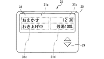
図2は、実施の形態1の給湯システム1が備える台所リモコン25の外観図である。台所リモコン25及び浴室リモコン26は、同一または類似の基本構成を有する。以下では、代表して台所リモコン25を例に説明するが、浴室リモコン26についても台所リモコン25と同様である。   FIG. 2 is an external view of the kitchen remote controller 25 provided in the hot water supply system 1 of the first embodiment. The kitchen remote controller 25 and the bathroom remote controller 26 have the same or similar basic configuration. In the following, the kitchen remote controller 25 will be described as an example, but the bathroom remote controller 26 is the same as the kitchen remote controller 25.

図2に示すように、台所リモコン25は、操作部29及び表示部30を備える。操作部29は、ユーザーが操作する複数の入力スイッチを有する。ユーザーは、操作部29を操作することで、例えば、給湯温度の設定、湯はり動作、追い焚き動作等の指令または予約、蓄熱運転の制御モードの選択、「水供給モード」の設定/非設定、などに関する入力操作を行うことができる。表示部30は、例えば、液晶表示パネル、有機EL表示パネルなどのフラットディスプレイパネルを用いて構成される。表示部30は、文字、図形、キャラクタ等を視覚表示することで情報を表示できる。表示部30は、表示手段の例である。台所リモコン25は、音声ガイダンス装置などをさらに備えてもよい。   As shown in FIG. 2, the kitchen remote control 25 includes an operation unit 29 and a display unit 30. The operation unit 29 has a plurality of input switches operated by the user. The user operates the operation unit 29 to set, for example, a hot water supply temperature, a command or reservation for hot water operation, a reheating operation, etc., selection of a heat storage operation control mode, and setting / non-setting of a “water supply mode” , Etc. can be input. The display unit 30 is configured using, for example, a flat display panel such as a liquid crystal display panel or an organic EL display panel. The display unit 30 can display information by visually displaying characters, figures, characters, and the like. The display unit 30 is an example of display means. The kitchen remote controller 25 may further include a voice guidance device or the like.

図2は、表示部30の表示画面がトップ画面31であるときの状態を表す。トップ画面31は、蓄熱運転の制御モードに関する設定情報31aと、現在時刻31bと、蓄熱運転が実行中か否かの運転情報31cと、貯湯タンク4内にある湯量または熱量の情報である残湯熱量情報31dとを含む。   FIG. 2 shows a state when the display screen of the display unit 30 is the top screen 31. The top screen 31 includes setting information 31a related to the control mode of the heat storage operation, the current time 31b, operation information 31c indicating whether or not the heat storage operation is being performed, and the amount of hot water or the amount of heat in the hot water storage tank 4 And calorie information 31d.

図2に示すトップ画面31の例では、以下のようになっている。設定情報31aとして「おまかせ」の文字が表示されている。これは、「おまかせモード」が設定されていることを示す。運転情報31cとして「わき上げ中」の文字が表示されている。これは、蓄熱運転が実行中であることを示す。残湯熱量情報31dとして「残湯100L」の文字が表示されている。これは、貯湯タンク4内にある湯量または熱量が、所定温度に換算して100Lであることを示す。   The example of the top screen 31 shown in FIG. 2 is as follows. As the setting information 31a, “Omakase” is displayed. This indicates that the “automatic mode” is set. The characters “Uplifting” are displayed as the driving information 31c. This indicates that the heat storage operation is being executed. Characters “residual hot water 100L” are displayed as the residual hot water calorie information 31d. This indicates that the amount of hot water or heat in the hot water storage tank 4 is 100 L in terms of a predetermined temperature.

設定情報31aは、貯湯式給湯機2の設定に関する第一情報の例である。第一情報は、この例に限られるものではなく、例えば、給湯温度の設定値に関する情報を含んでもよい。   The setting information 31 a is an example of first information regarding the setting of the hot water storage type hot water heater 2. 1st information is not restricted to this example, For example, you may include the information regarding the setting value of hot water supply temperature.

運転情報31c及び残湯熱量情報31dは、貯湯式給湯機2の状態に関する第二情報の例である。第二情報は、この例に限られるものではなく、例えば、湯はり動作、追い焚き動作、蛇口への給湯などが実行中か否かに関する情報を含んでもよい。   The operation information 31 c and the remaining hot water calorie information 31 d are examples of second information related to the state of the hot water storage type hot water heater 2. The second information is not limited to this example, and may include, for example, information regarding whether or not a hot water operation, a chasing operation, hot water supply to a faucet, or the like is being executed.

図2に示す例では、文字を用いて第一情報及び第二情報を表示しているが、図形、キャラクタ等を用いて第一情報及び第二情報を表示してもよい。トップ画面31は、第一情報及び第二情報のいずれか一方のみを含むものでもよい。   In the example illustrated in FIG. 2, the first information and the second information are displayed using characters, but the first information and the second information may be displayed using graphics, characters, and the like. The top screen 31 may include only one of the first information and the second information.

本実施の形態では、制御装置50と、台所リモコン25及び浴室リモコン26との間は、共通の配線を介して接続されている。制御装置50は、貯湯式給湯機2の状態に関する情報などのデータを、宛先情報と共に送信することで、台所リモコン25宛ての情報と、浴室リモコン26宛ての情報とを区別して送信することができる。   In the present embodiment, the control device 50 and the kitchen remote controller 25 and the bathroom remote controller 26 are connected via a common wiring. The control device 50 can transmit information such as information related to the state of the hot water storage hot water heater 2 together with the destination information, so that the information addressed to the kitchen remote control 25 and the information addressed to the bathroom remote control 26 can be distinguished and transmitted. .

本実施の形態では、制御装置50に対して、蛇口への1日の積算給湯量の目標値を設定可能である。ユーザーは、台所リモコン25または浴室リモコン26の操作部29を操作することで、蛇口への1日の積算給湯量の目標値を設定できる。制御装置50は、給湯量計算部50eにより計算された当日の蛇口への積算給湯量が当該目標値を超えた場合には、例えば台所リモコン25及び浴室リモコン26の少なくとも一方からの音声案内によりユーザーに対して報知することで、蛇口の湯を使いすぎであることをユーザーに注意喚起してもよい。蛇口への1日の積算給湯量の目標値をユーザーが設定することに代えて、制御装置50が、過去所定期間に学習した実績値などに基づいて、蛇口への1日の積算給湯量の目標値を設定してもよい。   In the present embodiment, it is possible to set the target value of the daily accumulated hot water supply amount to the faucet for the control device 50. The user can set the target value of the daily hot water supply amount to the faucet by operating the operation unit 29 of the kitchen remote controller 25 or the bathroom remote controller 26. When the integrated hot water supply amount to the faucet calculated by the hot water supply amount calculation unit 50e exceeds the target value, the control device 50 uses, for example, voice guidance from at least one of the kitchen remote controller 25 and the bathroom remote controller 26 for the user. May alert the user that the tap water has been used too much. Instead of the user setting a target value of the daily hot water supply amount to the faucet, the control device 50 determines the daily hot water supply amount to the faucet based on the actual value learned in the past predetermined period. A target value may be set.

同様にして、ユーザーは、台所リモコン25または浴室リモコン26の操作部29を操作することで、浴槽への1日の積算給湯量の目標値を設定してもよい。制御装置50は、給湯量計算部50eにより計算された当日の浴槽への積算給湯量が当該目標値を超えた場合には、例えば台所リモコン25及び浴室リモコン26からの音声案内によりユーザーに対して報知することで、浴槽の湯を使いすぎであることをユーザーに注意喚起してもよい。   Similarly, the user may set the target value of the daily hot water supply amount to the bathtub by operating the operation unit 29 of the kitchen remote controller 25 or the bathroom remote controller 26. When the accumulated hot water supply amount to the bathtub of the day calculated by the hot water supply amount calculation unit 50e exceeds the target value, the control device 50 notifies the user by voice guidance from the kitchen remote controller 25 and the bathroom remote controller 26, for example. By notifying the user, the user may be alerted that the bath water is being used too much.

以下に説明するように、本実施の形態の給湯システム1は、給湯が停止した直後に、台所リモコン25及び浴室リモコン26の表示部30に、給湯量に関する第三情報を含むガイダンス表示を行う機能を有する。ガイダンス表示の実施を希望しないユーザーのために、給湯システム1は、ユーザーがガイダンス表示のON/OFFを設定可能にする手段を備えてもよい。例えば、ユーザーが台所リモコン25または浴室リモコン26の操作部29を操作することで、ガイダンス表示のON/OFFを設定できるように構成してもよい。   As will be described below, the hot water supply system 1 according to the present embodiment has a function of performing guidance display including third information related to the amount of hot water supply on the display unit 30 of the kitchen remote control 25 and the bathroom remote control 26 immediately after the hot water supply is stopped. Have For a user who does not wish to perform the guidance display, the hot water supply system 1 may include means for enabling the user to set the guidance display ON / OFF. For example, the guidance display may be set to ON / OFF by the user operating the operation unit 29 of the kitchen remote controller 25 or the bathroom remote controller 26.

次に、給湯停止直後の台所リモコン25及び浴室リモコン26の表示部30におけるガイダンス表示について、図3及び図4に基づいて説明する。図3は、実施の形態1の給湯システム1の制御動作を示すフローチャートである。   Next, guidance display on the display unit 30 of the kitchen remote controller 25 and the bathroom remote controller 26 immediately after the hot water supply is stopped will be described with reference to FIGS. FIG. 3 is a flowchart showing a control operation of hot water supply system 1 according to the first embodiment.

図3のステップS1で、給湯検知部50dは、給湯用流量センサ19の出力に基づいて、蛇口への給湯が実行されているか否かを判断する。蛇口への給湯が実行中である場合、すなわち蛇口への給湯が開始した場合には、ステップS2へ移行する。蛇口への給湯が実行中でない場合、すなわち蛇口への給湯が開始していない場合には、ステップS1を繰り返す。   In step S1 of FIG. 3, the hot water supply detection unit 50d determines whether or not hot water supply to the faucet is being performed based on the output of the hot water supply flow rate sensor 19. When hot water supply to the faucet is being executed, that is, when hot water supply to the faucet has started, the process proceeds to step S2. If hot water supply to the faucet is not being executed, that is, if hot water supply to the faucet has not started, step S1 is repeated.

蛇口への給湯が停止した直後を除き、蛇口への給湯が非実行中のときには、台所リモコン25及び浴室リモコン26の表示部30は、原則として、図2で説明したトップ画面31を表示している。「原則として」とは、例えば、表示部30の表示画面が変わるようなユーザー操作が操作部29に入力されない限り、という意味である。また、蛇口への給湯が実行中のときには、台所リモコン25及び浴室リモコン26の表示部30は、原則として、トップ画面31を表示している。すなわち、蛇口への給湯の最中に、台所リモコン25及び浴室リモコン26の表示部30は、トップ画面31の表示を継続する。これにより、以下のような効果が得られる。浴室でユーザーがシャワーを使用しているときに、台所にいる他のユーザーは、台所リモコン25のトップ画面31を見ることを妨げられることがない。また、台所の流し台でユーザーが食器洗いをしているときに、浴室にいる他のユーザーは、浴室リモコン26のトップ画面31を見ることを妨げられることがない。したがって、各ユーザーが、設定情報31a、運転情報31c、あるいは残湯熱量情報31dなどの情報を見ることの利便性の低下を防止できる。   When the hot water supply to the faucet is not being executed except immediately after the hot water supply to the faucet is stopped, the display unit 30 of the kitchen remote control 25 and the bathroom remote control 26 basically displays the top screen 31 described in FIG. Yes. “In principle” means, for example, unless a user operation that changes the display screen of the display unit 30 is input to the operation unit 29. In addition, when hot water is being supplied to the faucet, the display unit 30 of the kitchen remote controller 25 and the bathroom remote controller 26 displays the top screen 31 in principle. That is, during the hot water supply to the faucet, the display unit 30 of the kitchen remote control 25 and the bathroom remote control 26 continues to display the top screen 31. Thereby, the following effects are obtained. When the user is using the shower in the bathroom, other users in the kitchen are not prevented from seeing the top screen 31 of the kitchen remote control 25. Further, when the user is washing the dishes at the kitchen sink, other users in the bathroom are not prevented from seeing the top screen 31 of the bathroom remote control 26. Therefore, it is possible to prevent the convenience of each user from seeing information such as the setting information 31a, the operation information 31c, or the remaining hot water heat quantity information 31d.

ステップS2で、給湯量計算部50eは、ステップS1からステップS2へ移行した後の給湯用流量センサ19の給湯流量を積算することで、今回の蛇口への給湯が開始した後の給湯量を計算する。ステップS2からステップS3へ移行する。   In step S2, the hot water supply amount calculation unit 50e calculates the hot water supply amount after the hot water supply to the current faucet starts by integrating the hot water supply flow rate of the hot water supply flow rate sensor 19 after shifting from step S1 to step S2. To do. The process proceeds from step S2 to step S3.

ステップS3で、給湯量計算部50eは、当日の蛇口への積算給湯量を計算する。すなわち、給湯量計算部50eは、ステップS2で計算した給湯量と、今回の蛇口への給湯が開始する前における当日の蛇口への積算給湯量とを加算することで、現時点までの当日の蛇口への積算給湯量を計算する。ステップS3からステップS4へ移行する。   In step S3, the hot water supply amount calculation unit 50e calculates the integrated hot water supply amount to the faucet on that day. That is, the hot water supply amount calculation unit 50e adds the hot water supply amount calculated in step S2 and the accumulated hot water supply amount to the faucet on the current day before the hot water supply to the current faucet starts, so Calculate the total hot water supply to The process proceeds from step S3 to step S4.

ステップS4で、計時部50cは、今回の蛇口への給湯が開始してから現時点までの給湯連続時間を計時する。ステップS4からステップS5へ移行する。   In step S4, the timer 50c measures the continuous hot water supply time from the start of hot water supply to the faucet this time. The process proceeds from step S4 to step S5.

ステップS5で、給湯検知部50dは、給湯用流量センサ19の出力に基づいて、蛇口への給湯が実行されているか否かを判断する。蛇口への給湯が実行中である場合、すなわち今回の蛇口への給湯がまだ停止せずに続いている場合には、ステップS2へ戻る。蛇口への給湯が実行中でない場合、すなわち今回の蛇口への給湯が停止した場合には、ステップS6へ移行する。   In step S5, the hot water supply detection unit 50d determines whether or not hot water supply to the faucet is being performed based on the output of the hot water supply flow rate sensor 19. When the hot water supply to the faucet is being executed, that is, when the hot water supply to the faucet is not stopped yet, the process returns to step S2. When the hot water supply to the faucet is not being executed, that is, when the hot water supply to the faucet this time is stopped, the process proceeds to step S6.

ステップS6で、表示制御部50bは、ステップS4で計時された今回の蛇口への給湯連続時間が30秒以上かどうかを判断する。給湯連続時間が30秒未満の場合には、本ルーチンを終了する。この場合、台所リモコン25及び浴室リモコン26の表示部30におけるガイダンス表示は実施されず、台所リモコン25及び浴室リモコン26の表示部30は、トップ画面31の表示を継続する。   In step S6, the display control unit 50b determines whether or not the continuous hot water supply time to the current faucet timed in step S4 is 30 seconds or more. When the hot water supply continuous time is less than 30 seconds, this routine ends. In this case, the guidance display on the display unit 30 of the kitchen remote control 25 and the bathroom remote control 26 is not performed, and the display unit 30 of the kitchen remote control 25 and the bathroom remote control 26 continues to display the top screen 31.

給湯連続時間が30秒以上の場合には、ステップS6からステップS7へ移行する。ステップS7で、表示制御部50bは、浴室リモコン26宛てに、今回蛇口湯量、本日蛇口湯量、及び目標蛇口湯量に関する情報と、給湯停止直後のガイダンス表示を実施する指令情報とを送信する。これらの情報を受信した浴室リモコン26の表示部30は、給湯停止直後のガイダンス表示を実施する。   When the hot water supply continuous time is 30 seconds or more, the process proceeds from step S6 to step S7. In step S <b> 7, the display control unit 50 b transmits to the bathroom remote controller 26 information related to the current faucet hot water amount, the current faucet hot water amount, and the target faucet hot water amount, and command information for performing guidance display immediately after the hot water supply is stopped. The display unit 30 of the bathroom remote control 26 that has received the information performs a guidance display immediately after the hot water supply is stopped.

図4は、実施の形態1の給湯システム1のガイダンス表示を示す図である。図4に示すように、浴室リモコン26の表示部30は、以下のようにして、給湯停止直後のガイダンス表示を実施する。まず、表示部30の画面が、トップ画面31から第1のガイダンス画面32に切り替えられる。第1のガイダンス画面32は、一時的に表示される。第1のガイダンス画面32が表示される時間は、例えば、5秒間でもよい。続いて、表示部30の画面が、第1のガイダンス画面32から第2のガイダンス画面33に切り替えられる。第2のガイダンス画面33は、一時的に表示される。第2のガイダンス画面33が表示される時間は、例えば、5秒間でもよい。その後、表示部30の画面が、第2のガイダンス画面33からトップ画面31に戻され、給湯停止直後のガイダンス表示を終了する。このように、ガイダンス表示が自動的に終了してトップ画面31に戻ることで、トップ画面31に戻すためのユーザー操作が不要であるので、利便性に優れる。   FIG. 4 is a diagram illustrating a guidance display of the hot water supply system 1 according to the first embodiment. As shown in FIG. 4, the display part 30 of the bathroom remote control 26 performs the guidance display immediately after the hot water supply stop as follows. First, the screen of the display unit 30 is switched from the top screen 31 to the first guidance screen 32. The first guidance screen 32 is temporarily displayed. The time for which the first guidance screen 32 is displayed may be, for example, 5 seconds. Subsequently, the screen of the display unit 30 is switched from the first guidance screen 32 to the second guidance screen 33. The second guidance screen 33 is temporarily displayed. The time for which the second guidance screen 33 is displayed may be, for example, 5 seconds. Thereafter, the screen of the display unit 30 is returned from the second guidance screen 33 to the top screen 31, and the guidance display immediately after the hot water supply is stopped is terminated. As described above, since the guidance display is automatically ended and the display returns to the top screen 31, no user operation for returning to the top screen 31 is required, which is excellent in convenience.

第1のガイダンス画面32は、今回蛇口湯量に関する情報と、本日蛇口湯量に関する情報とを含む。今回蛇口湯量とは、今回の蛇口への給湯の開始から停止までの給湯量のことである。今回蛇口湯量は、ステップS2で計算された値である。図4の例では、今回蛇口湯量が50Lであることをユーザーに知らせている。本日蛇口湯量とは、現時点までの当日の蛇口への積算給湯量のことである。本日蛇口湯量は、ステップS3で計算された値である。図4の例では、本日蛇口湯量が400Lであることをユーザーに知らせている。   The first guidance screen 32 includes information on the current amount of tap water and information on the amount of tap water today. The faucet amount this time is the amount of hot water supply from the start to the stop of the hot water supply to the faucet this time. The amount of tap water this time is the value calculated in step S2. In the example of FIG. 4, the user is informed that the amount of tap water is 50L this time. The amount of tap water today is the accumulated amount of hot water supplied to the tap on that day. The amount of tap water today is the value calculated in step S3. In the example of FIG. 4, the user is informed that the amount of tap water is 400L today.

第2のガイダンス画面33は、目標蛇口湯量に関する情報と、本日蛇口湯量に関する情報とを含む。目標蛇口湯量とは、前述した、蛇口への1日の積算給湯量の目標値のことである。図4の例では、目標蛇口湯量が500Lであることをユーザーに知らせている。本実施の形態であれば、目標蛇口湯量に関する情報と、本日蛇口湯量に関する情報とを同時に表示することで、蛇口の湯を使いすぎでないかどうかをユーザーに分かりやすく知らせることができる。   The 2nd guidance screen 33 contains the information regarding the amount of target tap hot water, and the information regarding the amount of tap water today. The target faucet hot water amount is the target value of the daily accumulated hot water supply amount to the faucet described above. In the example of FIG. 4, the user is informed that the target tap water amount is 500 L. According to the present embodiment, by simultaneously displaying information on the target faucet hot water amount and information on the faucet hot water amount today, it is possible to inform the user in an easy-to-understand manner whether or not the faucet hot water is being used excessively.

ステップS7からステップS8へ移行する。ステップS8で、表示制御部50bは、台所リモコン25宛てに、今回蛇口湯量、本日蛇口湯量、及び目標蛇口湯量に関する情報と、給湯停止直後のガイダンス表示を実施する指令情報とを送信する。これらの情報を受信した台所リモコン25の表示部30は、給湯停止直後のガイダンス表示を実施する。台所リモコン25のガイダンス表示は、図4で説明した浴室リモコン26のガイダンス表示と同様である。   The process proceeds from step S7 to step S8. In step S <b> 8, the display control unit 50 b transmits to the kitchen remote controller 25 information related to the current faucet hot water amount, today's faucet hot water amount, and target faucet hot water amount, and command information for performing guidance display immediately after the hot water supply is stopped. The display unit 30 of the kitchen remote control 25 that has received the information performs a guidance display immediately after the hot water supply is stopped. The guidance display of the kitchen remote control 25 is the same as the guidance display of the bathroom remote control 26 described with reference to FIG.

給湯停止直後のガイダンス表示のON/OFF設定がOFFに設定されている場合は、表示制御部50bは、今回蛇口湯量、本日蛇口湯量、及び目標蛇口湯量に関する情報と、給湯停止直後のガイダンス表示を実施する指令情報とを、浴室リモコン26及び台所リモコン25宛てに送信しない。この場合には、浴室リモコン26及び台所リモコン25は、給湯停止直後に上記のようなガイダンス表示を実施せず、表示部30をトップ画面31のままにする。これにより、ガイダンス表示の実施を希望しないユーザーにも対応できる。   When the ON / OFF setting of the guidance display immediately after the hot water supply stop is set to OFF, the display control unit 50b displays information on the current tap water amount, the current tap water amount, and the target tap water amount, and the guidance display immediately after the hot water supply stop. The command information to be executed is not transmitted to the bathroom remote controller 26 and the kitchen remote controller 25. In this case, the bathroom remote controller 26 and the kitchen remote controller 25 do not perform the guidance display as described above immediately after the hot water supply is stopped, and the display unit 30 remains the top screen 31. Thereby, it is possible to cope with a user who does not wish to perform guidance display.

今回蛇口湯量は、給湯の開始から停止までの給湯量に関する第三情報の例である。本実施の形態であれば、給湯が停止した後に、貯湯式給湯機2の設定に関する第一情報及び貯湯式給湯機2の状態に関する第二情報を含むトップ画面31に代えて、第三情報を含む第1のガイダンス画面32を表示することで、以下の効果が得られる。ユーザーは、給湯の利用を停止した直後に、台所リモコン25または浴室リモコン26の表示部30に視線を向ける可能性が高い。トップ画面31から第1のガイダンス画面32へ切り替わるときの視覚的な効果がユーザーの視線を引き付けることができる。第一情報及び第二情報の少なくとも一方の情報に代えて第三情報を表示することで、第三情報の表示面積を大きくできる。これらのことから、第三情報、すなわち今回の給湯量に関する情報をユーザーに確実に知らせることができる。その結果、ユーザーの湯の使いすぎを確実に抑制できる。   The faucet hot water amount is an example of third information regarding the hot water supply amount from the start to the stop of the hot water supply. In the present embodiment, after the hot water supply is stopped, the third information is displayed instead of the top screen 31 including the first information related to the setting of the hot water storage type hot water heater 2 and the second information related to the state of the hot water storage type hot water heater 2. By displaying the first guidance screen 32 including the following, the following effects can be obtained. There is a high possibility that the user looks at the display unit 30 of the kitchen remote controller 25 or the bathroom remote controller 26 immediately after the use of the hot water supply is stopped. The visual effect when switching from the top screen 31 to the first guidance screen 32 can attract the user's line of sight. By displaying the third information instead of at least one of the first information and the second information, the display area of the third information can be increased. Accordingly, the user can be surely notified of the third information, that is, information on the current hot water supply amount. As a result, excessive use of the user's hot water can be reliably suppressed.

前述したように、本実施の形態であれば、蛇口への給湯の最中は、台所リモコン25及び浴室リモコン26の表示部30は、トップ画面31の表示を継続する。このため、浴室でユーザーがシャワーを長時間使用している場合でも、台所にいる他のユーザーが台所リモコン25のトップ画面31の情報を確認したいときにそれを妨げることがない。また、台所の流し台でユーザーが長時間食器洗いをしている場合でも、浴室にいる他のユーザーが浴室リモコン26のトップ画面31の情報を確認したいときにそれを妨げることがない。   As described above, in the present embodiment, the display unit 30 of the kitchen remote controller 25 and the bathroom remote controller 26 continues to display the top screen 31 during hot water supply to the faucet. For this reason, even when the user uses the shower for a long time in the bathroom, it is not hindered when another user in the kitchen wants to check the information on the top screen 31 of the kitchen remote controller 25. Further, even when the user has been washing dishes for a long time at the kitchen sink, when other users in the bathroom want to check the information on the top screen 31 of the bathroom remote control 26, this is not hindered.

本実施の形態では、台所リモコン25の表示部30にガイダンス画面32,33が表示されるタイミング(ステップS8)に比べて、浴室リモコン26の表示部30にガイダンス画面32,33が表示されるタイミング(ステップS7)が早い。これにより、以下のような効果が得られる。一般的に、台所にて蛇口を使用していたユーザーよりも、浴室で蛇口(シャワー)を使用していたユーザーの方が、リモコンを見やすい場所にいることが多い。このため、浴室リモコン26に先に情報を送信し、ガイダンス画面32,33をより早く表示させることで、利便性がより高くなる。なお、浴室リモコン26の表示部30は、浴室内表示部の例であり、台所リモコン25の表示部30は、浴室外表示部の例である。   In the present embodiment, the timing at which the guidance screens 32, 33 are displayed on the display unit 30 of the bathroom remote control 26, compared to the timing at which the guidance screens 32, 33 are displayed on the display unit 30 of the kitchen remote control 25 (step S8). (Step S7) is early. Thereby, the following effects are obtained. In general, a user who uses a faucet (shower) in a bathroom is more likely to see the remote control than a user who uses the faucet in the kitchen. For this reason, the convenience is further enhanced by transmitting information to the bathroom remote control 26 first and displaying the guidance screens 32 and 33 earlier. The display unit 30 of the bathroom remote control 26 is an example of a display unit in the bathroom, and the display unit 30 of the kitchen remote control 25 is an example of a display unit outside the bathroom.

本実施の形態では、ステップS6の処理を行うことで、以下の効果が得られる。給湯の開始から停止までの時間、すなわち給湯連続時間が基準(例えば30秒)に満たないときには、ガイダンス表示を実施せず、トップ画面31を維持する。蛇口からの細切れの短時間の出湯、あるいは蛇口からの意図しない少量の出湯のときに、ガイダンス表示がされてしまうと、ユーザーに対し、表示部30の表示がチラつくことによる煩わしさ、あるいは違和感を与える可能性がある。本実施の形態であれば、そのようなことを防止できる。給湯連続時間に代えて、給湯の開始から停止までの給湯量が基準(例えば30L)に満たないときに、ガイダンス表示を実施せず、トップ画面31を維持するようにしてもよい。その場合でも、上記と類似の効果が得られる。   In the present embodiment, the following effects can be obtained by performing the process of step S6. When the time from the start to the stop of hot water supply, that is, the continuous hot water supply time is less than a standard (for example, 30 seconds), the guidance screen is not displayed and the top screen 31 is maintained. If the guidance display is displayed at the time of short-time hot water discharge from the faucet or a small amount of unintentional hot water from the faucet, the troublesomeness or discomfort caused by the display on the display unit 30 flickering to the user. May give. In the present embodiment, such a situation can be prevented. Instead of the hot water supply continuous time, when the amount of hot water supply from the start to the stop of hot water supply is less than a standard (for example, 30 L), the guidance screen is not displayed and the top screen 31 may be maintained. Even in that case, an effect similar to the above can be obtained.

制御装置50は、「水供給モード」が設定されている場合には、給湯停止直後のガイダンス表示を実施しないように制御してもよい。「水供給モード」が設定されているときには湯が一切使用されない、と誤って認識しているユーザーがいる可能性がある。前述したように、実際には、「水供給モード」が設定されているときにも、一般給湯側電動混合弁7の弁体の隙間から微小な湯の漏れが発生することで、湯の使用量はゼロにはならない。そのような僅かな使用量に対して給湯量の情報を表示してしまうと、ユーザーに不要な違和感を与える可能性がある。そのような可能性を排除するため、「水供給モード」が設定されている場合には、給湯停止直後のガイダンス表示を実施しないことが望ましい。   When the “water supply mode” is set, the control device 50 may perform control so as not to perform the guidance display immediately after the hot water supply is stopped. There is a possibility that some users mistakenly recognize that no hot water is used when the “water supply mode” is set. As described above, in practice, even when the “water supply mode” is set, a small amount of hot water leaks from the gap of the valve body of the general hot water supply side electric mixing valve 7, so that hot water is used. The amount will not be zero. If the information on the amount of hot water supply is displayed for such a small amount of use, there is a possibility of giving the user an unnecessary discomfort. In order to eliminate such a possibility, when the “water supply mode” is set, it is desirable not to display the guidance immediately after the hot water supply is stopped.

本日蛇口湯量は、当日の積算給湯量に関する第四情報の例である。本実施の形態では、第1のガイダンス画面32にて、第四情報(本日蛇口湯量)を第三情報(今回蛇口湯量)と共に表示している。このような構成に限らず、第三情報(今回蛇口湯量)が表示された後に第四情報(本日蛇口湯量)を表示してもよい。   Today's faucet hot water amount is an example of the fourth information related to the accumulated hot water supply amount on that day. In the present embodiment, on the first guidance screen 32, the fourth information (the amount of faucet hot water today) is displayed together with the third information (the amount of faucet hot water this time). Not only such a configuration but also the fourth information (today faucet hot water amount) may be displayed after the third information (current tap water amount) is displayed.

目標蛇口湯量は、1日の積算給湯量の目標値に関する第五情報の例である。本実施の形態では、第2のガイダンス画面33にて、第五情報(目標蛇口湯量)を第四情報(本日蛇口湯量)と共に表示している。このような構成に限らず、第四情報(本日蛇口湯量)が表示された後に第五情報(目標蛇口湯量)を表示してもよい。   The target faucet hot water amount is an example of fifth information relating to a target value of the accumulated hot water supply amount per day. In the present embodiment, on the second guidance screen 33, the fifth information (target tap water amount) is displayed together with the fourth information (today tap water amount). Not only in such a configuration, the fifth information (target tap water amount) may be displayed after the fourth information (today tap water amount) is displayed.

本実施の形態では、蛇口への給湯に対する給湯停止後のガイダンス表示を実施する場合を例に説明した。このような例に限らず、浴槽への給湯に対する給湯停止後のガイダンス表示を同じようにして実施してもよい。その場合には、風呂用流量センサ21で検知される情報に基づいて、ガイダンス画面に表示する情報を作成できる。当該ガイダンス画面には、今回の浴槽への給湯量(今回ふろ湯量)、当日の浴槽への積算給湯量(本日ふろ湯量)、一日の浴槽への積算給湯量の目標値(目標ふろ湯量)などの情報を表示してもよい。制御装置50は、蛇口への給湯停止後のガイダンス表示と、浴槽への給湯停止後のガイダンス表示とを区別する種別情報とともに、給湯量などの情報を台所リモコン25及び浴室リモコン26に送信すればよい。   In the present embodiment, the case where guidance display after hot water supply stop for hot water supply to the faucet has been described has been described as an example. Not only such an example but the guidance display after the hot water supply stop with respect to the hot water supply to a bathtub may be implemented similarly. In that case, information to be displayed on the guidance screen can be created based on the information detected by the bath flow sensor 21. On the guidance screen, the amount of hot water supplied to the bathtub this time (the amount of hot water supplied this time), the amount of hot water supplied to the bathtub of the day (the amount of hot water supplied today), and the target value of the amount of hot water supplied to the bathtub for the day (target amount of bath water) Such information may be displayed. If the control device 50 transmits information such as the amount of hot water supply to the kitchen remote control 25 and the bathroom remote control 26 together with the type information for distinguishing between the guidance display after the hot water supply stop to the faucet and the guidance display after the hot water supply stop to the bathtub, Good.

実施の形態1の給湯システム1が備える制御装置50の各機能は、処理回路により実現されてもよい。制御装置50の処理回路は、少なくとも1つのプロセッサと少なくとも1つのメモリとを備えてもよい。処理回路が少なくとも1つのプロセッサと少なくとも1つのメモリとを備える場合、制御装置50の各機能は、ソフトウェア、ファームウェア、またはソフトウェアとファームウェアとの組み合わせにより実現されてもよい。ソフトウェアおよびファームウェアの少なくとも一方は、プログラムとして記述されてもよい。ソフトウェアおよびファームウェアの少なくとも一方は、少なくとも1つのメモリに格納されてもよい。少なくとも1つのプロセッサは、少なくとも1つのメモリに記憶されたプログラムを読み出して実行することにより、制御装置50の各機能を実現してもよい。少なくとも1つのメモリは、不揮発性または揮発性の半導体メモリ、磁気ディスク等を含んでもよい。   Each function of control device 50 included in hot water supply system 1 of the first embodiment may be realized by a processing circuit. The processing circuit of the control device 50 may include at least one processor and at least one memory. When the processing circuit includes at least one processor and at least one memory, each function of the control device 50 may be realized by software, firmware, or a combination of software and firmware. At least one of software and firmware may be described as a program. At least one of the software and firmware may be stored in at least one memory. The at least one processor may realize each function of the control device 50 by reading and executing a program stored in at least one memory. The at least one memory may include a nonvolatile or volatile semiconductor memory, a magnetic disk, or the like.

制御装置50の処理回路は、少なくとも1つの専用のハードウェアを備えてもよい。処理回路が少なくとも1つの専用のハードウェアを備える場合、処理回路は、例えば、単一回路、複合回路、プログラム化したプロセッサ、並列プログラム化したプロセッサ、ASIC(Application Specific Integrated Circuit)、FPGA(Field−Programmable Gate Array)、またはこれらを組み合わせたものでもよい。制御装置50の各部の機能がそれぞれ処理回路で実現されても良い。また、制御装置50の各部の機能がまとめて処理回路で実現されても良い。制御装置50の各機能について、一部を専用のハードウェアで実現し、他の一部をソフトウェアまたはファームウェアで実現してもよい。処理回路は、ハードウェア、ソフトウェア、ファームウェア、またはこれらの組み合わせによって、制御装置50の各機能を実現しても良い。   The processing circuit of the control device 50 may include at least one dedicated hardware. When the processing circuit includes at least one dedicated hardware, the processing circuit may be, for example, a single circuit, a composite circuit, a programmed processor, a parallel programmed processor, an ASIC (Application Specific Integrated Circuit), or an FPGA (Field-). (Programmable Gate Array) or a combination thereof. The function of each unit of the control device 50 may be realized by a processing circuit. Further, the functions of the respective units of the control device 50 may be realized together by a processing circuit. A part of each function of the control device 50 may be realized by dedicated hardware, and the other part may be realized by software or firmware. The processing circuit may realize each function of the control device 50 by hardware, software, firmware, or a combination thereof.

単一の制御装置により給湯システム1の動作が制御される構成に限定されるものではなく、複数の制御装置が連携することで給湯システム1の動作を制御する構成にしてもよい。   The configuration is not limited to the configuration in which the operation of the hot water supply system 1 is controlled by a single control device, and the configuration may be such that the operation of the hot water supply system 1 is controlled by cooperation of a plurality of control devices.

1 給湯システム、 2 貯湯式給湯機、 3 貯湯ユニット、 4 貯湯タンク、 5a 第1の温度センサ、 5b 第2の温度センサ、 5c 第3の温度センサ、 5d 第4の温度センサ、 5e 温度センサ、 6 温度センサ、 7 一般給湯側電動混合弁、 8 給湯管、 9 給水管、 10 混合給湯管、 11 風呂給湯側電動混合弁、 12 風呂側循環回路、 13 電磁弁、 14 風呂循環ポンプ、 15 熱交換器、 16 タンク側循環回路、 17 循環ポンプ、 18 混合風呂管、 19 給湯用流量センサ、 20 給湯用温度センサ、 21 風呂用流量センサ、 22 風呂用温度センサ、 23 給水温度センサ、 24 蓄熱回路、 25 台所リモコン、 26 浴室リモコン、 27 循環ポンプ、 28 ヒートポンプユニット、 29 操作部、 30 表示部、 31 トップ画面、 31a 設定情報、 31b 現在時刻、 31c 運転情報、 31d 残湯熱量情報、 32 第1のガイダンス画面、 33 第2のガイダンス画面、 50 制御装置、 50a 蓄熱運転制御部、 50b 表示制御部、 50c 計時部、 50d 給湯検知部、 50e 給湯量計算部、 50f モード設定部 DESCRIPTION OF SYMBOLS 1 Hot water supply system, 2 Hot water storage type water heater, 3 Hot water storage unit, 4 Hot water storage tank, 5a 1st temperature sensor, 5b 2nd temperature sensor, 5c 3rd temperature sensor, 5d 4th temperature sensor, 5e Temperature sensor, 6 Temperature sensor, 7 General hot water supply side electric mixing valve, 8 Hot water supply pipe, 9 Water supply pipe, 10 Mixed hot water supply pipe, 11 Bath hot water supply side electric mixing valve, 12 Bath side circulation circuit, 13 Solenoid valve, 14 Bath circulation pump, 15 Heat Exchanger, 16 Tank side circulation circuit, 17 Circulation pump, 18 Mixed bath pipe, 19 Flow rate sensor for hot water supply, 20 Temperature sensor for hot water supply, 21 Flow rate sensor for bath, 22 Temperature sensor for bath, 23 Water temperature sensor, 24 Heat storage circuit , 25 Kitchen remote control, 26 Bathroom remote control, 27 Circulation pump, 28 Heat pump unit , 29 operation unit, 30 display unit, 31 top screen, 31a setting information, 31b current time, 31c operation information, 31d residual heat quantity information, 32 first guidance screen, 33 second guidance screen, 50 control device, 50a Thermal storage operation control unit, 50b display control unit, 50c timing unit, 50d hot water detection unit, 50e hot water supply amount calculation unit, 50f mode setting unit

Claims (7)

給湯機と、
前記給湯機からの給湯が実行されているか否かを検知する手段と、
前記給湯機からの給湯量を計算する手段と、
表示手段と、
前記表示手段の表示を制御する制御手段と、
を備え、
前記給湯機からの給湯の実行中のとき、及び、給湯停止後を除く前記給湯機からの給湯の非実行中のときには、前記給湯機の設定に関する第一情報及び前記給湯機の状態に関する第二情報の少なくとも一方の情報が前記表示手段に表示され、前記給湯機からの給湯が停止した後には当該給湯の開始から停止までの給湯量に関する第三情報が、前記第一情報及び前記第二情報の少なくとも一方の情報に代えて、一時的に前記表示手段に表示される給湯システム。
A water heater,
Means for detecting whether hot water supply from the water heater is being executed;
Means for calculating the amount of hot water supplied from the water heater;
Display means;
Control means for controlling the display of the display means;
With
When hot water is being supplied from the water heater, and when hot water is not being executed from the water heater except after hot water is stopped, first information relating to the setting of the water heater and second relating to the state of the water heater At least one of the information is displayed on the display means, and after the hot water supply from the water heater is stopped, the third information regarding the hot water supply amount from the start to the stop of the hot water supply is the first information and the second information. Instead of at least one of the information, a hot water supply system temporarily displayed on the display means.
前記第三情報が表示された後に、または、前記第三情報と共に、当日の積算給湯量に関する第四情報が一時的に前記表示手段に表示される請求項1に記載の給湯システム。   4. The hot water supply system according to claim 1, wherein after the third information is displayed, or together with the third information, fourth information relating to the accumulated hot water supply amount on the day is temporarily displayed on the display means. 前記第四情報が表示された後に、または、前記第四情報と共に、1日の積算給湯量の目標値に関する第五情報が一時的に前記表示手段に表示される請求項2に記載の給湯システム。   5. The hot water supply system according to claim 2, wherein after the fourth information is displayed, or together with the fourth information, fifth information related to a target value of an integrated hot water supply amount per day is temporarily displayed on the display unit. . 給湯の開始から停止までの時間または給湯量が基準に満たないときには、前記給湯機からの給湯が停止した後に前記第三情報が前記表示手段に表示されない請求項1から請求項3のいずれか一項に記載の給湯システム。   The third information is not displayed on the display means after the hot water supply from the water heater is stopped when the time from the start to the stop of the hot water supply or the amount of hot water supply is less than the standard. The hot water supply system according to item. 前記表示手段は、浴室に設置される浴室内表示部と、前記浴室以外の場所に設置される浴室外表示部とを備え、
前記給湯機からの給湯が停止した後に前記浴室外表示部に前記第三情報が表示されるタイミングに比べて前記浴室内表示部に前記第三情報が表示されるタイミングが早い請求項1から請求項4のいずれか一項に記載の給湯システム。
The display means includes a display unit in the bathroom installed in the bathroom, and a display unit outside the bathroom installed in a place other than the bathroom,
The timing at which the third information is displayed on the display section in the bathroom is earlier than the timing at which the third information is displayed on the display section outside the bathroom after the hot water supply from the water heater is stopped. Item 5. A hot water supply system according to any one of items 4 to 6.
前記給湯機からの給湯が停止した後に前記第三情報を前記表示手段に表示するか否かをユーザーが事前に設定可能にする手段を備える請求項1から請求項5のいずれか一項に記載の給湯システム。   6. The apparatus according to claim 1, further comprising a unit that allows a user to set in advance whether or not to display the third information on the display unit after hot water supply from the water heater is stopped. Hot water system. 高温水と、水源から供給される低温水とを混合する混合手段と、
前記低温水の混合割合を最大に固定する水供給モードを設定可能にする手段と、
を備え、
前記水供給モードが設定されているときには前記給湯機からの給湯が停止した後に前記第三情報が前記表示手段に表示されない請求項1から請求項6のいずれか一項に記載の給湯システム。
A mixing means for mixing high-temperature water and low-temperature water supplied from a water source;
Means capable of setting a water supply mode for fixing the mixing ratio of the low-temperature water to the maximum;
With
The hot water supply system according to any one of claims 1 to 6, wherein when the water supply mode is set, the third information is not displayed on the display means after hot water supply from the water heater is stopped.
JP2016062268A 2016-03-25 2016-03-25 Hot water supply system Active JP6623881B2 (en)

Priority Applications (1)

Application Number Priority Date Filing Date Title
JP2016062268A JP6623881B2 (en) 2016-03-25 2016-03-25 Hot water supply system

Applications Claiming Priority (1)

Application Number Priority Date Filing Date Title
JP2016062268A JP6623881B2 (en) 2016-03-25 2016-03-25 Hot water supply system

Publications (2)

Publication Number Publication Date
JP2017172936A true JP2017172936A (en) 2017-09-28
JP6623881B2 JP6623881B2 (en) 2019-12-25

Family

ID=59970812

Family Applications (1)

Application Number Title Priority Date Filing Date
JP2016062268A Active JP6623881B2 (en) 2016-03-25 2016-03-25 Hot water supply system

Country Status (1)

Country Link
JP (1) JP6623881B2 (en)

Cited By (2)

* Cited by examiner, † Cited by third party
Publication number Priority date Publication date Assignee Title
JP2019113212A (en) * 2017-12-21 2019-07-11 三菱電機株式会社 Water heater
JP2020125862A (en) * 2019-02-01 2020-08-20 三菱電機株式会社 Hot water storage type hot water supply device

Citations (11)

* Cited by examiner, † Cited by third party
Publication number Priority date Publication date Assignee Title
JPS63187050A (en) * 1987-01-29 1988-08-02 Matsushita Electric Ind Co Ltd Hot water accumulation type hot water heater
JP2006258338A (en) * 2005-03-16 2006-09-28 Matsushita Electric Ind Co Ltd Display device and program
JP2011141088A (en) * 2010-01-07 2011-07-21 Gastar Corp Water heater
JP2012017956A (en) * 2010-07-09 2012-01-26 Panasonic Electric Works Co Ltd Hot water supply system
JP2013015284A (en) * 2011-07-05 2013-01-24 Mitsubishi Electric Corp Storage type water heater
JP2013050304A (en) * 2012-12-12 2013-03-14 Mitsubishi Electric Corp Storage type hot water supply system
JP2013113524A (en) * 2011-11-30 2013-06-10 Noritz Corp Remote control apparatus and heat source machine
JP2013178010A (en) * 2012-02-28 2013-09-09 Denso Corp Storage type water heater
JP2013221689A (en) * 2012-04-17 2013-10-28 Hitachi Appliances Inc Water heater
JP2013245846A (en) * 2012-05-24 2013-12-09 Hitachi Appliances Inc Water heater
JP2014155031A (en) * 2013-02-08 2014-08-25 Corona Corp Remote controller of heat source apparatus

Patent Citations (11)

* Cited by examiner, † Cited by third party
Publication number Priority date Publication date Assignee Title
JPS63187050A (en) * 1987-01-29 1988-08-02 Matsushita Electric Ind Co Ltd Hot water accumulation type hot water heater
JP2006258338A (en) * 2005-03-16 2006-09-28 Matsushita Electric Ind Co Ltd Display device and program
JP2011141088A (en) * 2010-01-07 2011-07-21 Gastar Corp Water heater
JP2012017956A (en) * 2010-07-09 2012-01-26 Panasonic Electric Works Co Ltd Hot water supply system
JP2013015284A (en) * 2011-07-05 2013-01-24 Mitsubishi Electric Corp Storage type water heater
JP2013113524A (en) * 2011-11-30 2013-06-10 Noritz Corp Remote control apparatus and heat source machine
JP2013178010A (en) * 2012-02-28 2013-09-09 Denso Corp Storage type water heater
JP2013221689A (en) * 2012-04-17 2013-10-28 Hitachi Appliances Inc Water heater
JP2013245846A (en) * 2012-05-24 2013-12-09 Hitachi Appliances Inc Water heater
JP2013050304A (en) * 2012-12-12 2013-03-14 Mitsubishi Electric Corp Storage type hot water supply system
JP2014155031A (en) * 2013-02-08 2014-08-25 Corona Corp Remote controller of heat source apparatus

Cited By (4)

* Cited by examiner, † Cited by third party
Publication number Priority date Publication date Assignee Title
JP2019113212A (en) * 2017-12-21 2019-07-11 三菱電機株式会社 Water heater
JP7000841B2 (en) 2017-12-21 2022-01-19 三菱電機株式会社 Water heater
JP2020125862A (en) * 2019-02-01 2020-08-20 三菱電機株式会社 Hot water storage type hot water supply device
JP7172670B2 (en) 2019-02-01 2022-11-16 三菱電機株式会社 Storage hot water heater

Also Published As

Publication number Publication date
JP6623881B2 (en) 2019-12-25

Similar Documents

Publication Publication Date Title
JP2007285653A (en) Hot water supply device
JP5310576B2 (en) Hot water supply system
JP6623881B2 (en) Hot water supply system
JP2013130334A (en) Hot water storage type water heater
JP2015137802A (en) hot water storage type water heater
JP2011149570A (en) Warm water supply system
JP2018105607A (en) Water heater
JP2008008563A (en) Storage type hot-water supply method and storage type hot-water supply device
JP6439599B2 (en) Water heater
JP4674654B1 (en) Water heater
JP2017203577A (en) Hot water supply system
JP5571489B2 (en) Hot water storage water heater
JP2011149581A (en) Hot water supply system
JP2013221689A (en) Water heater
JP2018071952A (en) Hot water storage type water heater
JP2011002123A (en) Storage type water heater
JP4998576B2 (en) Water heater
JP2003166748A (en) Heat-pump type hot water supply device
JP6790933B2 (en) Water heater
JP2018132231A (en) Water heater
JP2009162415A (en) Hot water storage type water heater
JP2006138493A (en) Hot water storage type water heater
JP2009133574A (en) Water heater
JP2017083073A (en) Remote control for heat pump device and heat pump device using the same
JP5287745B2 (en) Hot water supply system and controller

Legal Events

Date Code Title Description
A621 Written request for application examination

Free format text: JAPANESE INTERMEDIATE CODE: A621

Effective date: 20180614

A977 Report on retrieval

Free format text: JAPANESE INTERMEDIATE CODE: A971007

Effective date: 20190308

A131 Notification of reasons for refusal

Free format text: JAPANESE INTERMEDIATE CODE: A131

Effective date: 20190402

A521 Request for written amendment filed

Free format text: JAPANESE INTERMEDIATE CODE: A523

Effective date: 20190509

TRDD Decision of grant or rejection written
A01 Written decision to grant a patent or to grant a registration (utility model)

Free format text: JAPANESE INTERMEDIATE CODE: A01

Effective date: 20191029

A61 First payment of annual fees (during grant procedure)

Free format text: JAPANESE INTERMEDIATE CODE: A61

Effective date: 20191111

R150 Certificate of patent or registration of utility model

Ref document number: 6623881

Country of ref document: JP

Free format text: JAPANESE INTERMEDIATE CODE: R150

R250 Receipt of annual fees

Free format text: JAPANESE INTERMEDIATE CODE: R250

R250 Receipt of annual fees

Free format text: JAPANESE INTERMEDIATE CODE: R250