JP2017158764A5 - - Google Patents
Download PDFInfo
- Publication number
- JP2017158764A5 JP2017158764A5 JP2016045244A JP2016045244A JP2017158764A5 JP 2017158764 A5 JP2017158764 A5 JP 2017158764A5 JP 2016045244 A JP2016045244 A JP 2016045244A JP 2016045244 A JP2016045244 A JP 2016045244A JP 2017158764 A5 JP2017158764 A5 JP 2017158764A5
- Authority
- JP
- Japan
- Prior art keywords
- image
- function
- image processing
- information
- processing apparatus
- Prior art date
- Legal status (The legal status is an assumption and is not a legal conclusion. Google has not performed a legal analysis and makes no representation as to the accuracy of the status listed.)
- Pending
Links
- 230000003287 optical Effects 0.000 claims description 23
- 238000000034 method Methods 0.000 claims description 8
- 238000001514 detection method Methods 0.000 claims description 6
- 238000005315 distribution function Methods 0.000 claims description 6
- 238000003384 imaging method Methods 0.000 claims 14
- 238000005286 illumination Methods 0.000 claims 1
- 238000003672 processing method Methods 0.000 claims 1
- 238000010586 diagram Methods 0.000 description 14
- 238000004364 calculation method Methods 0.000 description 5
- 230000015556 catabolic process Effects 0.000 description 3
- 230000000875 corresponding Effects 0.000 description 3
- 230000004059 degradation Effects 0.000 description 3
- 238000006731 degradation reaction Methods 0.000 description 3
- 230000001629 suppression Effects 0.000 description 3
Images
Description
また、他の一例として、参照符号10bで示した内視鏡の構成例は、光学素子12をカメラヘッド13の一部として構成した場合の一例である。具体的には、内視鏡10bにおいては、カメラヘッド13bのうち、鏡筒11bに装着される側の端部に光学素子12bが保持されている。このような構成により、鏡筒11bにより集光された光がカメラヘッド13bに入射する際に、光学素子12bを通過することとなる。このような構成であれば、専用の内視鏡ではなく、従来の内視鏡を用いて、被写界深度拡大処理を行う事が可能となり得る。 Further, as another example, the configuration example of the endoscope indicated by reference numeral 10 b is an example in the case where the optical element 12 is configured as a part of the camera head 13. Specifically, in the endoscope 10b, the optical element 12b is held at the end of the camera head 13b on the side to be attached to the lens barrel 11b. With such a configuration, when the light collected by the lens barrel 11b enters the camera head 13b, it passes through the optical element 12b. With such a configuration, it is possible to perform the depth-of-field enlargement process using a conventional endoscope instead of a dedicated endoscope.
PSF記憶部512は、PSF取得部511により取得されたPSF情報を記憶するための構成である。PSF記憶部512は、例えば、所謂データベース(DB)として構成されていてもよい。PSF記憶部512は、各機器(即ち、鏡筒11、光学素子12、カメラヘッド13等)に対応するPSF情報を、当該機器を示す情報や、当該PSF情報を取得するための条件(例えば、観察範囲の条件)を示す情報と関連付けて記憶する。より具体的な一例として、PSF記憶部512は、鏡筒11とカメラヘッド13との組み合わせ、光学素子12の装着の有無、及び当該光学素子12の種類等のように、光学的な特性が変化する組み合わせごとにPSF情報を記憶してもよい。なお、この場合には、前述したPSF取得部511は、光学的な特性が変化する組み合わせごとにPSF情報を取得してもよい。 The PSF storage unit 512 is a configuration for storing PSF information acquired by the PSF acquisition unit 511. The PSF storage unit 512 may be configured as, for example, a so-called database (DB). The PSF storage unit 512 includes PSF information corresponding to each device (ie, the lens barrel 11, the optical element 12, the camera head 13 and the like), information indicating the device, and a condition for acquiring the PSF information (eg, The information is stored in association with the information indicating the condition of the observation range. As a more specific example, the PSF storage unit 512 changes optical characteristics such as a combination of the lens barrel 11 and the camera head 13, presence / absence of attachment of the optical element 12, and type of the optical element 12 or the like. PSF information may be stored for each combination. In this case, the PSF acquisition unit 511 described above may acquire PSF information for each combination in which the optical characteristic changes.
画像処理部517は、選択部516からPSF情報を取得し、カメラヘッド13により撮像された画像を入力画像として、当該入力画像に対して取得したPSF情報に基づき復元処理を施すことで、被写体像の画像の劣化(即ち、ボケ)を改善する。当該復元処理としては、例えば、所謂デコンボリューションと称される処理が挙げられる。より具体的な一例として、画像処理部517は、入力画像に対して取得したPSF情報の逆特性に基づく画像処理(例えば、フィルタ処理)を施すことで、当該PSF情報が示す光学的特性に応じて生じる画像の劣化(ボケ)を改善する。もちろん、PSF情報に基づき、被写体像の画像の劣化を改善することが可能であれば、入力画像に対して施される復元処理は、必ずしもデコンボリューションのみには限定されない。なお、画像処理部517により復元処理が施された画像は、例えば、図1に示す表示装置53を介してユーザに提示される。 The image processing unit 517 obtains PSF information from the selection unit 516, and uses the image captured by the camera head 13 as an input image, performs restoration processing on the input image based on the obtained PSF information, and thereby obtains a subject image. Image degradation (ie, blurring) is improved . As the said decompression | restoration process, the process called what is called a deconvolution is mentioned, for example. As a more specific example, the image processing unit 517 performs an image process (for example, a filter process) based on the inverse characteristic of the acquired PSF information on the input image, according to the optical characteristic indicated by the PSF information. Improve the image degradation (blur) that occurs. Of course, as long as degradation of the image of the subject image can be improved based on the PSF information, the restoration processing applied to the input image is not necessarily limited to only deconvolution. The image subjected to the restoration processing by the image processing unit 517 is presented to the user via, for example, the display device 53 shown in FIG.
以上、図7〜図10を参照して、図1に示したCCU51の構成のうち、特に、画像処理装置として動作する部分の機能構成の一例について説明した。 Above, with reference to FIGS. 7 to 10, of the configuration of CCU51 shown in FIG. 1, in particular, it has been described an example of a functional configuration of the portion operating as the image processing apparatus.
<3.2.画像処理装置の処理>
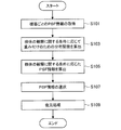
次いで、図11を参照して、本実施形態に係る画像処理装置510の一連の処理の流れの一例について説明する。図11は、本実施形態に係る画像処理装置510の一連の処理の流れの一例について示したフローチャートである。
<3.2. Image Processing Device Processing>
Next, with reference to FIG. 11, an example of the flow of a series of processes of the image processing apparatus 510 according to the present embodiment will be described. FIG. 11 is a flowchart showing an example of the flow of a series of processing of the image processing apparatus 510 according to the present embodiment .
そして、画像処理装置510(画像処理部517)は、カメラヘッド13により撮像された画像を入力画像として、当該入力画像に対して選択したPSF情報に基づき、被写体像の画像の劣化(即ち、ボケ)に対しデコンボリューション等の復元処理を施すことで、画像を復元する(S109)。なお、画像処理部517により復元処理が施された画像は、例えば、所定の表示装置を介してユーザに提示される。 Then, the image processing apparatus 510 (image processing unit 517) uses the image captured by the camera head 13 as an input image, and degrades the image of the object image (that is, blurs) based on the PSF information selected for the input image. The image is restored by performing restoration processing such as deconvolution on the image (S109). The image subjected to the restoration processing by the image processing unit 517 is presented to the user via, for example, a predetermined display device.
(実施例2−1:被写体の細かさに応じた制御)
まず、実施例2−1として、図16を参照して、合焦位置における被写体の細かさに応じて、PSF情報に対して重み付けを行うための分布関数の一例について説明する。図16は、実施例2−1に係る画像処理装置における、PSF情報の算出に係る制御の一例について説明するための説明図である。なお、以降の説明では、所定のAF(Auto Focus)方式に基づく焦点検出のための検波値を、「AF検波値」とも称する。なお、焦点検出は、画像内のコントラスト情報、輝度情報、エッジ情報等に基づき行われる。
(Example 2-1: Control according to the fineness of the subject)
First, as Example 2-1, an example of a distribution function for weighting PSF information according to the fineness of the subject at the in-focus position will be described with reference to FIG. FIG. 16 is an explanatory diagram for describing an example of control related to calculation of PSF information in the image processing apparatus according to Example 2-1. In the following description, a detection value for focus detection based on a predetermined AF (Auto Focus) method is also referred to as an "AF detection value". The focus detection is performed based on contrast information, brightness information, edge information and the like in the image.
以上、実施例2−1として、図16を参照して、合焦位置における被写体の細かさに応じて、PSF情報に対して重み付けを行うための分布関数の一例について説明した。 In the above, as Example 2-1, an example of the distribution function for weighting PSF information according to the fineness of the subject at the in-focus position has been described with reference to FIG.
一方で、画像処理装置510が、状態や状況を認識するような状況下においては、当該認識にミスが生じる場合もある。このような認識ミスに対して、例えば、画像処理装置510が、過敏に反応し、PSF情報が一時的に誤って切り替えられると、観察者に対して提示される画像の特性が一時的に替わり、検体の観察を阻害する場合も想定され得る。このような状況を鑑み、例えば、画像処理装置510に対して、短期的な状態や状況の変化に応じたPSF情報の切り替えを抑制するための仕組みを設けてもよい。 On the other hand, the image processing apparatus 510, in a situation such as to recognize the state and circumstances, it may miss the recognition results. For such recognition errors, for example, when the image processing apparatus 510 reacts hypersensitively and PSF information is temporarily switched erroneously, the characteristics of the image presented to the observer are temporarily changed. Also, it may be assumed that the observation of the sample is inhibited. In view of such a situation, for example, the image processing apparatus 510 may be provided with a mechanism for suppressing the switching of PSF information according to a short-term state or a change in the state.
例えば、図20において、上側に「入力」として示した図は、上述したPSF情報の切り替えの抑制に係る制御の適用前における、時系列に沿った一連のフレームF101〜F110と、当該各フレームに対して設定された観察モードとを模式的に示している。例えば、「入力」側の図において、フレームF101〜F105に着目すると、フレームF103においてのみ、観察モードが一時的にmodeAからmodeBに切り替わっている。また、フレームF106〜F110に着目した場合には、フレームF109においてのみ、観察モードが一時的にmodeCからmodeDに切り替わっている。このような場合には、例えば、フレームF103及びF109のタイミングにおいて、復元処理に適用されるPSF情報が一時的に切り替わるため、出力される画像の特性が一時的に変化する。 For example, in FIG. 20, the diagram shown as "input" on the upper side is a series of frames F101 to F110 along the time series and the respective frames before application of the control related to the suppression of PSF information switching described above. It shows schematically the observation mode set with respect to this. For example, in the figure on the “input” side, focusing on the frames F101 to F105, the observation mode is temporarily switched from mode A to mode B only in the frame F103. When attention is focused on the frames F106 to F110, the observation mode is temporarily switched from mode C to mode D only in the frame F109. In such a case , for example, since the PSF information applied to the restoration process is temporarily switched at the timing of frames F103 and F109, the characteristics of the output image are temporarily changed.
これに対して、図20において、下側に「出力」として示した図は、上述したPSF情報の切り替えの抑制に係る制御を適用した場合における、当該フレームF101〜F110と、当該各フレームに対して設定された観察モードとを模式的に示している。なお、「入力」側と「出力」側とで同じ符号が付されたフレームは、同じフレームを示している。例えば、「出力」側の図においては、例えば、フレームF103における観察モードが、前後のフレームにあわせてmodeAに修正されており、当該フレームF103に対する復元処理に適用されるPSF情報が、当該modeAに対応するPSF情報に切り替わる。同様に、フレームF109における観察モードについては、前後のフレームにあわせてmodeCに修正されており、当該フレームF109に対する復元処理に適用されるPSF情報が、当該modeCに対応するPSF情報に切り替わる。 On the other hand, in FIG. 20, the diagram shown as “output” on the lower side corresponds to the frames F101 to F110 and the respective frames in the case where the control related to the suppression of PSF information switching described above is applied. And the observation mode set in FIG. The frames to which the same reference numerals are attached on the “input” side and the “output” side indicate the same frame. For example, in the diagram on the “output” side, for example, the observation mode in frame F103 is corrected to mode A in accordance with the previous and subsequent frames, and PSF information applied to the restoration processing for the frame F103 is the mode A. Switch to corresponding PSF information. Similarly, the observation mode in the frame F109 is corrected to mode C in accordance with the preceding and succeeding frames, and PSF information applied to the restoration processing for the frame F109 is switched to PSF information corresponding to the mode C.
Claims (18)
補正画像を生成するよう制御する制御部を有し、
前記関数は、前記被写体の観察に関する条件に応じて算出された関数である、
画像処理装置。 Based on an image in which a subject is captured and a function for adjusting the amount of blur of the image,
Having a control unit that controls to generate a corrected image;
The function is a function calculated according to a condition regarding observation of the subject.
Image processing device.
前記制御部は、前記複数の関数のうち少なくともいずれかの当該関数に基づき、前記補正画像を生成するよう制御する、
請求項1に記載の画像処理装置。 The function is a plurality of functions whose conditions are different from each other, and
The control unit controls to generate the corrected image based on at least one of the plurality of functions.
The image processing apparatus according to claim 1.
請求項1に記載の画像処理装置。 The image processing apparatus according to claim 1, wherein the condition related to observation is detection information obtained from the image or an imaging condition of the image.
前記画像の色成分情報、エッジ情報、コントラスト情報、または輝度情報である
請求項3に記載の画像処理装置。 The detection information is
The image processing apparatus according to claim 3, which is color component information, edge information, contrast information, or luminance information of the image.
前記画像を撮像した際の照射光情報、フォーカス距離情報、フォーカス位置情報、フォーカス制御情報、フォーカスレンズ位置情報、光学ズーム制御情報、または光学ズームレンズ位置情報である
請求項3に記載の画像処理装置。 The imaging condition is
The image processing apparatus according to claim 3, wherein the light processing information is illumination light information when imaging the image, focus distance information, focus position information, focus control information, focus lens position information, optical zoom control information, or optical zoom lens position information. .
請求項2に記載の画像処理装置。 The image processing apparatus according to claim 2, wherein the control unit selects a function to be applied from the plurality of functions according to the condition, and controls to generate the corrected image based on the function.
請求項6に記載の画像処理装置。 The image processing apparatus according to claim 6, wherein the functions are a plurality of functions weighted according to the condition.
請求項6に記載の画像処理装置。 The image processing apparatus according to claim 6, wherein the function is a plurality of functions calculated based on a distribution function according to the condition.
前記撮像部により撮像された画像から補正画像を生成するよう制御する画像処理装置と、
を備え、
前記画像処理装置は、
前記画像と、前記画像のボケ量を調整するための関数に基づき、
補正画像を生成する制御部を有し、
前記関数は、前記被写体の観察に関する条件に応じて算出される、
医療用画像処理システム。 An imaging device including an imaging unit configured to capture an image of a specimen; and an optical system configured to form an object image of the specimen on the imaging unit;
An image processing apparatus configured to control to generate a corrected image from an image captured by the imaging unit;
Equipped with
The image processing apparatus is
Based on the image and a function to adjust the amount of blurring of the image,
Having a control unit that generates a corrected image;
The function is calculated according to a condition regarding observation of the subject.
Medical image processing system.
前記鏡筒と前記撮像部との間に、当該撮像部に被写体像を結像する光学系の振幅伝達関数を制御するための光学素子が介在し、
前記関数は、前記光学素子の特性に応じて算出された関数である、
請求項12に記載の医療用画像処理システム。 The lens barrel is configured to be removable from the imaging unit.
An optical element for controlling an amplitude transfer function of an optical system that forms an object image on the imaging unit is interposed between the lens barrel and the imaging unit.
The function is a function calculated according to the characteristics of the optical element.
The medical image processing system according to claim 12.
前記関数は、前記被写体の観察に関する条件に応じて算出された関数である、
画像処理方法。 Controlling the processor to generate a corrected image based on an image of the subject and a function for adjusting the amount of blur of the image;
The function is a function calculated according to a condition regarding observation of the subject.
Image processing method.
前記関数は、前記被写体の観察に関する条件に応じて算出された関数である、
プログラムが記録された記録媒体。 Allowing a computer to perform control to generate a corrected image based on an image obtained by capturing an object and a function for adjusting the amount of blur of the image;
The function is a function calculated according to a condition regarding observation of the subject.
Recording medium on which the program is recorded.
Priority Applications (8)
| Application Number | Priority Date | Filing Date | Title |
|---|---|---|---|
| JP2016045244A JP2017158764A (en) | 2016-03-09 | 2016-03-09 | Image processing device, image processing method, and recording medium |
| US16/071,299 US10799088B2 (en) | 2016-03-09 | 2017-02-03 | Image processing device, image processing method and recording medium |
| PCT/JP2017/004107 WO2017154434A1 (en) | 2016-03-09 | 2017-02-03 | Image processing device, image processing method and recording medium |
| CN201780014706.5A CN108697308B (en) | 2016-03-09 | 2017-02-03 | Image processing apparatus, image processing method, and recording medium |
| EP17705708.0A EP3426127B1 (en) | 2016-03-09 | 2017-02-03 | Image processing device, image processing method and recording medium |
| US17/026,324 US11642004B2 (en) | 2016-03-09 | 2020-09-21 | Image processing device, image processing method and recording medium |
| JP2021041870A JP2021094421A (en) | 2016-03-09 | 2021-03-15 | Image processing device, image processing method, and recording medium |
| JP2023071088A JP2023083547A (en) | 2016-03-09 | 2023-04-24 | Image processing device, image processing method, and recording medium |
Applications Claiming Priority (1)
| Application Number | Priority Date | Filing Date | Title |
|---|---|---|---|
| JP2016045244A JP2017158764A (en) | 2016-03-09 | 2016-03-09 | Image processing device, image processing method, and recording medium |
Related Child Applications (1)
| Application Number | Title | Priority Date | Filing Date |
|---|---|---|---|
| JP2021041870A Division JP2021094421A (en) | 2016-03-09 | 2021-03-15 | Image processing device, image processing method, and recording medium |
Publications (2)
| Publication Number | Publication Date |
|---|---|
| JP2017158764A JP2017158764A (en) | 2017-09-14 |
| JP2017158764A5 true JP2017158764A5 (en) | 2019-04-18 |
Family
ID=58054474
Family Applications (3)
| Application Number | Title | Priority Date | Filing Date |
|---|---|---|---|
| JP2016045244A Pending JP2017158764A (en) | 2016-03-09 | 2016-03-09 | Image processing device, image processing method, and recording medium |
| JP2021041870A Pending JP2021094421A (en) | 2016-03-09 | 2021-03-15 | Image processing device, image processing method, and recording medium |
| JP2023071088A Pending JP2023083547A (en) | 2016-03-09 | 2023-04-24 | Image processing device, image processing method, and recording medium |
Family Applications After (2)
| Application Number | Title | Priority Date | Filing Date |
|---|---|---|---|
| JP2021041870A Pending JP2021094421A (en) | 2016-03-09 | 2021-03-15 | Image processing device, image processing method, and recording medium |
| JP2023071088A Pending JP2023083547A (en) | 2016-03-09 | 2023-04-24 | Image processing device, image processing method, and recording medium |
Country Status (5)
| Country | Link |
|---|---|
| US (2) | US10799088B2 (en) |
| EP (1) | EP3426127B1 (en) |
| JP (3) | JP2017158764A (en) |
| CN (1) | CN108697308B (en) |
| WO (1) | WO2017154434A1 (en) |
Families Citing this family (15)
| Publication number | Priority date | Publication date | Assignee | Title |
|---|---|---|---|---|
| CN110785111B (en) * | 2017-06-20 | 2021-12-21 | 奥林巴斯株式会社 | Medical display device |
| WO2019082278A1 (en) * | 2017-10-24 | 2019-05-02 | オリンパス株式会社 | Endoscope device and operation method of endoscope device |
| JP2019080623A (en) | 2017-10-27 | 2019-05-30 | ソニー・オリンパスメディカルソリューションズ株式会社 | Endoscope apparatus |
| US10462412B2 (en) | 2018-01-30 | 2019-10-29 | Manish Eknath Ingle | Surgical visualization and recording system |
| JP7143092B2 (en) * | 2018-03-12 | 2022-09-28 | ソニー・オリンパスメディカルソリューションズ株式会社 | Medical image processing device, medical observation device, and image processing method |
| WO2020196387A1 (en) | 2019-03-28 | 2020-10-01 | ソニー株式会社 | Signal processing device, signal processing method, program and medical image processing system |
| CN110266980B (en) * | 2019-07-04 | 2021-08-03 | 上海索倍信息科技有限公司 | Depth field depth television display |
| US20220346631A1 (en) * | 2019-09-25 | 2022-11-03 | Sony Group Corporation | Imaging optical system and imaging apparatus |
| EP4047408A4 (en) * | 2019-11-22 | 2022-12-28 | Sony Group Corporation | Image processing method, image processing device, and image processing system |
| CA3168826A1 (en) | 2020-01-22 | 2021-07-29 | Photonic Medical Inc. | Open view, multi-modal, calibrated digital loupe with depth sensing |
| WO2022044898A1 (en) | 2020-08-31 | 2022-03-03 | ソニーグループ株式会社 | Medical imaging system, medical imaging device, and operation method |
| DE102020211380A1 (en) * | 2020-09-10 | 2022-03-10 | Carl Zeiss Microscopy Gmbh | Process for super-resolution evaluation of structured illuminated microscope images and microscope with structured illumination |
| EP4309358A1 (en) * | 2021-03-15 | 2024-01-24 | Sony Group Corporation | An imaging system, method and computer program product for an imaging device |
| CN114488511A (en) * | 2021-12-23 | 2022-05-13 | 南京大学 | Depth measurement auxiliary imaging-based extended depth-of-field optical fiber endoscopic imaging method |
| WO2023195326A1 (en) * | 2022-04-05 | 2023-10-12 | オリンパス株式会社 | Endoscope system, procedure supporting method, and procedure supporting program |
Family Cites Families (28)
| Publication number | Priority date | Publication date | Assignee | Title |
|---|---|---|---|---|
| JPH0837604A (en) * | 1994-05-17 | 1996-02-06 | Olympus Optical Co Ltd | Image processor |
| JP3532368B2 (en) * | 1996-12-10 | 2004-05-31 | 富士写真フイルム株式会社 | Endoscope |
| JPH10290780A (en) * | 1997-04-18 | 1998-11-04 | Olympus Optical Co Ltd | Endoscope image pickup device |
| JPH11183809A (en) * | 1997-12-24 | 1999-07-09 | Olympus Optical Co Ltd | Image pickup device for endoscope |
| JP2000005127A (en) * | 1998-01-23 | 2000-01-11 | Olympus Optical Co Ltd | Endoscope system |
| JP3548507B2 (en) | 2000-08-01 | 2004-07-28 | キヤノン株式会社 | Radiation imaging device |
| US7365721B2 (en) * | 2002-07-08 | 2008-04-29 | Matsushita Electric Industrial Co., Ltd. | Projection display |
| CN1732472A (en) * | 2002-12-30 | 2006-02-08 | 皇家飞利浦电子股份有限公司 | Controllable two layer birefringent optical component |
| JP4492946B2 (en) * | 2004-07-08 | 2010-06-30 | 株式会社 液晶先端技術開発センター | Light irradiation apparatus, crystallization apparatus, and crystallization method |
| US7423727B2 (en) * | 2005-01-25 | 2008-09-09 | Asml Netherlands B.V. | Lithographic apparatus and device manufacturing method |
| EP1978753A4 (en) * | 2006-01-20 | 2012-07-04 | Acutelogic Corp | Optical low pass filter and imaging device using the same |
| JP2010513969A (en) * | 2006-12-19 | 2010-04-30 | コーニンクレッカ フィリップス エレクトロニクス エヌ ヴィ | Lens structure of autostereoscopic display device |
| US7933509B2 (en) * | 2007-12-31 | 2011-04-26 | Motorola, Inc. | Device and method for reducing optical blurring |
| JP5250342B2 (en) * | 2008-08-26 | 2013-07-31 | 富士フイルム株式会社 | Image processing apparatus and program |
| JP5435916B2 (en) * | 2008-09-18 | 2014-03-05 | 富士フイルム株式会社 | Electronic endoscope system |
| JP2011072530A (en) | 2009-09-30 | 2011-04-14 | Fujifilm Corp | Imaging apparatus |
| WO2011045065A1 (en) | 2009-10-15 | 2011-04-21 | Sony Corporation | Birefringent device with application specific pupil function and optical device |
| JP5346856B2 (en) | 2010-03-18 | 2013-11-20 | オリンパス株式会社 | ENDOSCOPE SYSTEM, ENDOSCOPE SYSTEM OPERATING METHOD, AND IMAGING DEVICE |
| JP5657375B2 (en) * | 2010-12-24 | 2015-01-21 | オリンパス株式会社 | Endoscope apparatus and program |
| JP5864880B2 (en) * | 2011-04-07 | 2016-02-17 | オリンパス株式会社 | Endoscope apparatus and method for operating endoscope apparatus |
| JP5705096B2 (en) | 2011-12-02 | 2015-04-22 | キヤノン株式会社 | Image processing apparatus and image processing method |
| EP2868254B1 (en) | 2012-06-28 | 2018-04-04 | Olympus Corporation | Endoscope system |
| WO2014050191A1 (en) * | 2012-09-26 | 2014-04-03 | 富士フイルム株式会社 | Image processing device, imaging device, image processing method, and program |
| US20140185922A1 (en) * | 2012-12-27 | 2014-07-03 | Kabushiki Kaisha Toshiba | Image processing apparatus and image processing method |
| JP5863709B2 (en) * | 2013-06-04 | 2016-02-17 | 富士フイルム株式会社 | Endoscope system |
| CN103344569B (en) * | 2013-06-21 | 2015-10-28 | 中国科学院上海光学精密机械研究所 | Polarization complex frequency domain optical coherence tomography imaging method and system |
| JP6555881B2 (en) * | 2014-12-19 | 2019-08-07 | キヤノン株式会社 | Image processing apparatus, imaging apparatus, image processing method, image processing program, and storage medium |
| KR101850871B1 (en) * | 2015-08-26 | 2018-04-23 | 주식회사 디알텍 | Method for processing radiography image and radiography system |
-
2016
- 2016-03-09 JP JP2016045244A patent/JP2017158764A/en active Pending
-
2017
- 2017-02-03 WO PCT/JP2017/004107 patent/WO2017154434A1/en active Application Filing
- 2017-02-03 US US16/071,299 patent/US10799088B2/en active Active
- 2017-02-03 EP EP17705708.0A patent/EP3426127B1/en active Active
- 2017-02-03 CN CN201780014706.5A patent/CN108697308B/en active Active
-
2020
- 2020-09-21 US US17/026,324 patent/US11642004B2/en active Active
-
2021
- 2021-03-15 JP JP2021041870A patent/JP2021094421A/en active Pending
-
2023
- 2023-04-24 JP JP2023071088A patent/JP2023083547A/en active Pending
Similar Documents
| Publication | Publication Date | Title |
|---|---|---|
| JP2017158764A5 (en) | ||
| JP5484631B2 (en) | Imaging apparatus, imaging method, program, and program storage medium | |
| JP7036176B2 (en) | Display control device, display control method and display control program | |
| JP5380784B2 (en) | Autofocus device, imaging device, and autofocus method | |
| JPWO2006082967A1 (en) | Imaging device | |
| KR101599872B1 (en) | Digital photographing apparatus method for controlling the same and recording medium storing program to implement the method | |
| JP5676956B2 (en) | Image processing apparatus, image processing method, and program | |
| WO2007086378A1 (en) | Best-focus detector | |
| US20120092514A1 (en) | Image-capture device, a method of correcting images, and a non-transitory computer-readable storage medium | |
| JP5653464B2 (en) | Imaging apparatus, image processing apparatus, image processing method, image processing program, and storage medium | |
| JP2020088403A (en) | Image processing apparatus, control method therefor and program | |
| JP2010154306A (en) | Device, program and method for imaging control | |
| JP6501536B2 (en) | Imaging device, control method therefor, program, storage medium | |
| JPWO2019188934A1 (en) | Imaging device, imaging method, and program | |
| JP6834988B2 (en) | Control device | |
| JP6436840B2 (en) | Image processing apparatus, imaging apparatus, image processing method, image processing program, and storage medium | |
| JP2015204566A (en) | camera system | |
| KR20100098122A (en) | Image processing method and apparatus, and digital photographing apparatus using thereof | |
| JP2017063340A (en) | Image blur correction device, imaging device, and control method | |
| US10277796B2 (en) | Imaging control apparatus, imaging apparatus, and imaging control method | |
| JP2014138378A (en) | Image pickup device, control method thereof, and control program thereof | |
| JP2020085967A (en) | Image processor, method for controlling the same, and program | |
| WO2021065065A1 (en) | Imaging device | |
| US11283989B1 (en) | Digital camera with multi-subject focusing | |
| WO2016157569A1 (en) | Imaging device and focus evaluation device |